![]()
4-я Красноармейская, 2А
Санкт-Петербург, 190005
Email: info@lenmoto.ru
Телефон: +7 (921) 930-81-18
Телефон: +7 (911) 928-08-06
Компания ЛенМото
Запчасти, аксессуары, экипировка, тюнинг для мотоциклов, скутеров, квадроциклов, снегоходов, багги, гидроциклов, катеров и лодочных моторов.
Подпишитесь на наши новости
Подписаться
-
Contents
-
Table of Contents
-
Bookmarks
Related Manuals for BMW R 1100 RT
Summary of Contents for BMW R 1100 RT
-
Page 1
Repair Manual R 1100 RT R 1100 RS R 850/1100 GS R 850/1100 R BMW Motorcycle After Sales… -
Page 2
Published by: © BMW Motorcycle After Sales UX-VS-2 All rights reserved. Not to be reprinted, translated or duplicated either wholly or in part without prior written permission. Errors and omissions excepted; subject to technical amendment. Produced in Germany 02/00… -
Page 3
All information in both text and illustrations refers to motorcycles in standard condition or with genuine BMW accessories installed, and not to motorcycles which have been modified in any way to depart from the manufacturer’s specification. The repair manual is structured in the logical sequence of the work to be performed: Removal, Dis- assembly, Repair, Assembly, Installation. -
Page 4
Contents << Back Group / Chapter 00 Maintenance and general instructions 11 Motor 12 Engine electrics 13 Fuel preparation and control 16 Fuel tank and lines 18 Exhaust system 21 Clutch 23 Gearbox 31 Front fork 32 Steering 33 Rear wheel drive >>… -
Page 5
>> Continuation Group / Chapter 34 Brakes 36 Wheels and tyres 46 Frame 51 Equipment 52 Seat 61 General electrical equipment 62 Instruments 63 Lights << Back… -
Page 6
BMW AG Motorcycle Division Maintenance Schedule R 1100 RT/R 1100 RS/R 850 GS/R 1100 GS/R 850R/R 1100 R Customer Registration No. Order No. Signature of mechanic Change engine oil when engine is warm, renew oil filter cartridge Change oil in manual transmission and rear wheel drive when at operating temperature… -
Page 7
BMW AG Motorcycle Division Pre-delivery check R 1100 RT/R 1100 RS/R 850 GS/R 1100 GS/R 850R/R 1100 R Customer Registration No. Pre-delivery check Order No. Signature of mechanic Inspect crates on receipt for signs of damage Motorcycle: – unpack –… -
Page 8: Service Data
BMW AG Motorcycle Division Service Data R 1100 RT/R 1100 RS/R 1100 GS/R 1100 R/R 850 R Designation Data Measuring unit or specification Oilcapacities Engine (incl. filter) 3.75 litre Engine (without filter renewal) 5.50 litre [SI 11 048 90] Brand-name HD oil for petrol engines of API classi- fication SE, SF, SG;…
-
Page 9: Maintenance And General Instructions
00 Maintenance and general instructions Contents Page Tightening torques R 1100 RS / R 1100 RT …………..3 Tightening torques R 850/1100 GS und R 850/1100 R ………..12 Operating materials ……………………21 Key to maintenance intervals ………………..22 Change engine oil, renew oil filter element …………..22…
-
Page 10: Table Of Contents
Contents Page Checking brake pads for wear ………………..32 Renewing brake pads – front brake ………………32 [RS] Renewing brake pads — rear brake …………….33 [GS/R/RT] Renewing brake pads — rear brake …………..33 Checking brake discs for wear ………………..33 Checking brake fluid level/topping up …………….33 (Inspection III) ……………………….33 Bleeding/renewing the brake fluid using the handbrake lever/…
-
Page 11: Tightening Torques R 1100 Rs / R 1100 Rt
Tightening torques R 1100 RS / R 1100 RT Model R 1100 RS R 1100 RT 11 Engine Connection Cylinder head Tightening sequence: 1. Tighten cylinder head nuts (oiled) crosswise 1.1 Tighten all nuts to correct torque for joint 1.2 Tighten all nuts to correct angle 90°…
-
Page 12
Model R 1100 RS R 1100 RT 11 Engine Connection Oil filter Oil filter Oil drain plug Oil pump Mesh filter basket to engine block Oil pump cover Pressure relief valve Oil pressure switch Oil cooler Oil cooler pipe to engine block… -
Page 13
Model R 1100 RS R 1100 RT 12 Engine electrical system Connection Starter motor to engine Starter cover to gearbox housing – Positive lead to starter motor Alternator to alternator support cover Tensioning and retaining strap at alternator Spacer at alternator… -
Page 14
Model R 1100 RS R 1100 RT 21 Clutch Connection Clutch housing Joint torque oil screw threads lightly Additional wrench angle 32° Housing cover Locknut on release lever 23 Gearbox Oil filler plug Oil drain plug Gearbox cover to gearbox housing… -
Page 15
Model R 1100 RS R 1100 RT 31 Front fork Connection Clamp between fixed tubes and fork bridge – Screw connection between fixed tube and – 45 (free from oil and fork bridge grease) Control arm to ball joint clean thread + Loctite 2701 Fork bridge to ball joint –… -
Page 16
Model R 1100 RS R 1100 RT 33 Rear wheel drive Connection Oil drain plug Oil filler plug Threaded ring 118 (Hylomar SQ 32 M) 118 (Hylomar SQ 32 M) Hexagon nut, input bevel gear clean thread + Loctite 273… -
Page 17
Model R 1100 RS R 1100 RT 34 Brakes Connection Brake caliper to slider tube Brake caliper to rear wheel drive Brake disc to front wheel Brake disc to rear wheel drive clean thread + Loctite 273 Brake hose to brake caliper, front/rear… -
Page 18
Model R 1100 RS R 1100 RT 46 Frame Connection Rear frame to gearbox/engine Screw connection on right of gearbo at right of engine at left of engine at left of gearbox Footrest plate to gearbox Frame to engine Struts to frame 8.8 screw… -
Page 19
Model R 1100 RS R 1100 RT 51 Equipment Connection Ignition/steering lock to fork bridg 61 General electrical system Horn to horn bracket Ground (earth) strap to engine block Rubber bushing for battery holder at gearbox 00.11… -
Page 20: Tightening Torques R 850/1100 Gs Und R 850/1100 R
Tightening torques R 850/1100 GS und R 850/1100 R Model R 850/1100 GS R 850/1100 R 11 Engine Connection Cylinder head Tightening sequence: 1. Tighten cylinder head nuts (oiled) crosswise 1.1 Tighten all nuts to correct torque for joint 1.2 Tighten all nuts to correct angle 90°…
-
Page 21
Model R 850/1100 GS R 850/1100 R 11 Engine Connection Oil filter Oil filter Oil drain plug Oil pump Mesh filter basket to engine block Oil pump cover Pressure relief valve Oil pressure switch Oil cooler Oil cooler pipe to engine block Cooling oil line — banjo screw Cooling oil line — banjo screw with oil vent valve Oil lines to oil cooler… -
Page 22
Model R 850/1100 GS R 850/1100 R 12 Engine electrical system Connection Starter motor to engine Starter cover to gearbox housing Positive lead to starter motor Alternator to alternator support cover Tensioning and retaining strap at alternator Spacer at alternator Positive lead to alternator Belt pulley at alternator Belt pulley to crankshaft… -
Page 23
Model R 850/1100 GS R 850/1100 R 21 Clutch Connection Clutch housing Joint torque oil screw threads lightly Additional wrench angle 32° Housing cover Locknut on release lever 23 Gearbox Oil filler plug Oil drain plug Gearbox cover to gearbox housing Screw for neutral detent clean thread + Loctite 243 Oil guide plate at gearbox housing… -
Page 24
Model R 850/1100 GS R 850/1100 R 31 Front fork Connection Screw connection between fixed tube and 45 (free from oil and 45 (free from oil and fork bridge grease) grease) Control arm to ball joint clean thread + Loctite 2701 Threaded journal to frame clean threads + Loctite 243 Ball joint to… -
Page 25
Model R 850/1100 GS R 850/1100 R 32 Steering Connection Handlebar to fork bridge Twistgrip to handlebar Handlebar weight to fixed handlebar 33 Rear wheel drive Oil drain plug Oil filler plug Threaded ring 118 (Hylomar SQ 32 M) 118 (Hylomar SQ 32 M) Hexagon nut, input bevel gear clean thread + Loctite 273 Housing cover… -
Page 26
Model R 850/1100 GS R 850/1100 R 34 Brakes Connection Brake caliper to slider tube Brake caliper to rear wheel drive Brake disc to front wheel Cast wheel – Spoked whee clean thread + Loctite 243 Brake disc to rear wheel drive clean thread + Loctite 273 Brake disc to rear wheel clean thread + Loctite 243… -
Page 27
Model R 850/1100 GS R 850/1100 R 36 Wheels and tyres Connection Clamping screws, quick-release axle Screw connection, quick-release axle Screw on wheel nuts handtight, then tighten crosswise: Initial tightening Final tightening 46 Frame Rear frame to gearbox/engine 1. Screw connection on right of gearbox 2. -
Page 28
Model R 850/1100 GS R 850/1100 R 51 Equipment Connection Ignition/steering lock to fork bridge 61 General electrical system Horn to horn bracket Ground (earth) strap to engine block Rubber bushing for battery holder at gearbox 00.20… -
Page 29: Operating Materials
Operating materials Item Order number Quantity Lubricant Optimoly MP 3 High-performance lubricating paste 07 55 9 062 476 100 g tube Optimoly TA High-temperature assembly paste 18 21 9 062 599 100 g tube Silicone grease 300, heavy Damping grease 07 58 9 058 193 10 g tube Retinax A (Taper) roller bearing grease…
-
Page 30: Key To Maintenance Intervals
11 4 650 RS000180 RS110950 • • Remove screw plug. Using oil filter wrench, BMW No. 11 4 650, • Unscrew oil drain plug and drain off oil. unscrew and remove the oil filter element. • • Fit new seal and screw in drain plug.
-
Page 31: Change The Oil In The Gearbox And Rear Wheel Drive
Top up gearbox oil. • Insert oil filler plug with new seal. • [RT] Push in oil drain pipe (1), BMW No. 23 4 680 and turn to right. • Unscrew and remove oil filler plug and oil drain Tightening torque: plug/drain off oil.
-
Page 32: Checking Battery Acid Level/Topping Up If Necessary, Cleaning/Greasing
R/GS/RT RS000340 Checking battery acid level/topping Renewing air cleaner up if necessary, cleaning/greasing (Inspection III) battery posts • Remove dualseat. • (Inspection III, IV) [GS] Detach fuel tank at rear, raise it and support it with a suitable object. • •…
-
Page 33: Renewing Fuel Filter
[RS/RT] Take off side sections of fairing. Seal off fuel feed and return line (3) with hose clip, • [RS] Detach cockpit inner panel (1) at fuel tank. BMW No. 13 3 010, loosen and pull off. • • [GS] Remove right side fairing.
-
Page 34
13 3 010 RT160060 00.26… -
Page 35
RS000130 Caution: Fuel is flammable and a hazard to health. Observe relevant safety regulations. • Drain fuel tank. • Remove fuel pump unit/detach vent hoses. 00.27… -
Page 36
• Installation in reverse order. • Secure non-reusable hose clips with pliers, BMW No. 13 1 500. Caution: Note correct direction of flow through fuel filter. Use only an O-ring seal (2) in good condition. After assembly, check fuel pump unit for leaks. -
Page 37: Checking/Renewing Spark Plugs
Pull off spark plug cap with cap assembly tool, BMW No. 12 3 520. • Unscrew and remove spark plugs with spark- plug wrench, BMW No. 12 3 510. Electrode gap: ……0.8 mm (0.0315 in) RS 00. 002 RS00002 Gap wear limit:……
-
Page 38: Checking/Adjusting Valve Operating Clearances
Checking/adjusting valve operating clearances (Inspection I, II, III) RS110980 • Check valve clearance with feeler gauge and, if necessary, correct with adjusting nut/lock. Adjust valve clearances with the engine cold (max. 35°C): Inlet ………. 0.15 mm ( 0.006 in) Exhaust ……..0.30 mm (0.012 in ) Tightening torque: Locknut …………
-
Page 39: Adjusting Poly-V Belt
RS110480 Adjusting Poly-V belt Poly-V belt adjusting procedure: Poly-V belt installation procedure: (Inspection I, II, III) • Place the Poly-V belt in position, tension it and turn the engine over once, then release belt ten- Renewing Poly-V belt sion. (40 000 km/24 000miles) Poly-V belt tensioning procedure: •…
-
Page 40: Checking Brake Pads And Discs For Wear/Renewing
Before installing the brake caliper, push the Brake pad thickness must not fall below the minimum pistons back fully with resetting tool, value. BMW No. 34 1 500. • Change pads only as a complete set. Install in the reverse order of work.
-
Page 41: Rs] Renewing Brake Pads — Rear Brake
Install in the reverse order of work. [RS] rear:……..4.6 mm (0.181 in) • If necessary, push pistons fully back with reset- ting tool, BMW No. 34 1 500. Checking brake fluid level/topping [GS/R/RT] Renewing brake pads — rear brake (Inspection III) Max.
-
Page 42: Bleeding Front Brake Circuit/Renewing Fluid
LT000100 • Press the brake pistons fully back with the piston resetting tool, BMW No. 34 1 500. • Remove the piston resetting tool and insert spacer, BMW No. 34 1 520, in its place. 00.34…
-
Page 43: Grease The Centre Stand [Rs], Side Stand And Clutch Cable Nipple
Grease the centre stand [RS], side [RS] Cleaning and greasing the stand and clutch cable nipple windshield adjusting shaft (Inspection II, III, IV) (Inspection III) RS000360 RS000330 • • Clean and grease the nipple with a grease gun Unscrew, clean and grease the shaft, then screw until grease starts to emerge at the bearing point.
-
Page 44
6 mm Allen key, BMW No. 31 5 600. • [RT] Slacken off the power socket holder. • Using socket wrench, BMW No. 21 3 610, slacken off locknut (1) at adjusting screw (2) on the clutch release lever/gearbox. 00.36… -
Page 45: Checking Tightness Of Rear Wheel Studs
Checking tightness of rear wheel Checking front wheel bearings/ studs checking tilt play at rear wheel (Inspection I) (Inspection III) • Relieve load on front wheel. • Tightening torque: Tilt the front wheel to and fro across the axle. • Rear wheel nuts ………
-
Page 46: Checking Throttle Synchronisation/Co Emission Value
Checking/adjusting throttle syn- chronisation and CO emission value (Inspection I, II, III, IV) RS130040 • Pre-adjust the wire connecting cable between the throttle stub pipes with the left or right ad- justing screw . RS130020 • Adjust the connecting cable to zero play. •…
-
Page 47
• • Connect the BMW Synchrotester, Set idle speed using recirculating air screws BMW No. 13 0 800, to the vacuum while maintaining synchronous running. bores in the throttle stub pipes. • Ride the motorcycle until the engine is warm, or… -
Page 48
• With cable junction block Connect the BMW Synchrotester, BMW No. 13 0 800, to the vacuum bores of the throttles.. • Ride the motorcycle until the engine is warm, or alternatively allow it to warm up at a standstill for approx. 10 minutes. -
Page 49
• Push the protective rubber cap (2) back over the adjusting screw. Throttle cable play:..app. 0.5 mm (0.0197 in) RT000140 • Rectify any faults found. • Set idle speed using recirculating air screws while maintaining synchronous running. RS 11.055 RT000080 + 150 Idle speed: …….. -
Page 50: Final Inspection With Road Safety And Functional Check
Final inspection with road safety and functional check (Inspection I, II, III, IV) Road safety check • Check wheels and tyres. • Check/correct tyre pressures. Tyre pressures: Rider only……front 2.2 bar(31.9 psi) ……….. rear 2.5 bar (36.26 psi) With pillion passenger ..front 2.5 bar(36.26 psi) ……….
-
Page 51: Motor
11 Motor Contents Page Technical Data ……………………..5 Sectioned drawing of engine ………………..37 Lubricating oil circuit …………………..38 Coolant circuit ……………………..39 Cooling oil circuit (with oil thermostat) …………….40 Removing engine ……………………41 Fitting auxiliary frame …………………….52 Take off auxiliary frame……………………53 Dismantling engine ……………………54 Removing cylinder head cover ………………..55…
-
Page 52
Contents Page Removing/installing conrod ………………….68 Removing and installing alternator cover with engine installed …….69 Removing alternator mount cover ………………69 Renewing radial shaft seal in alternator mount cover ………..70 Renewing radial shaft seal for rotary breather …………..70 Removing auxiliary-shaft drive ………………..71 Removing oil pump ……………………72 Oil temperature regulator… -
Page 53
Contents Page Installing auxiliary shaft drive ………………..88 Installing pistons ……………………..89 Installing cylinders ……………………90 Installing cylinder head …………………..91 Adjusting valve clearances …………………..92 Installing right cylinder head ………………..93 Adjustment specification ……………………93 Installing left cylinder head …………………..94 Adjustment specification ……………………94 Installing alternator mount cover ………………..96 Installing magnetic gate/belt pulley ………………96… -
Page 54
11.4… -
Page 55
Technical Data R 1100 RS Engine, general Engine design Four-stroke flat twin, air-cooled with oil-cooled exhaust ports, installed longitudinally, 4 valves per cylinder, two high-mounted camshafts, elec- tronic fuel injection. Location of engine number Crankcase Cylinder bore mm (in) 99.0 (3.898) Stroke mm (in) 70.5 (2.776) -
Page 56
Technical Data R 1100 RS Valves Included angle between valves ° Valve clearances, engine cold (max. 35 °C) Inlet valve mm (in) 0.15 (0.0059) Exhaust valve mm (in) 0.30 (0.0118) Valve timing Zero valve clearance. 3 mm (0.1181 in) valve lift Inlet opens 5°… -
Page 57
Technical Data R 1100 RS Valve seat ring Valve seat angle Inlet 45° Exhaust 30° from 1996 mod. year on Inlet 45° Exhaust 45° Valve seat width ± 0.15 Inlet mm (in) ± 0.00591 (0.04331 Wear limit mm (in) 2.5 (0.09843) ±… -
Page 58
Technical Data R 1100 RS Valve guide Valve guide Extl. dia. mm (in) 12.533…12.544 (0.49343…0.49386) Bore in cylinder head mm (in) 12.500…12.518 (0.49213…0.49283) Overlap mm (in) 0.015…0.044 (0.00059…0.001732) Repair stages Replacement valve guide Extl. dia. mm (in) 12.550…12.561 (0.49409…0.49453) Oversize valve guide Extl. -
Page 59
Technical Data R 1100 RS Camshaft Opening angle, inlet/exhaust cams 300° Cam spread, inlet/exhaust 106°/109° Marking Marking in position 4 Inlet valve lift mm (in) 9.68 (0.3811) (valve clearance = 0) Exhaust valve lift mm (in) 9.26 (0.36457) (valve clearance = 0) Camshaft bearing bore dia. -
Page 60
Technical Data R 1100 RS Crankshaft Marking of main bearing and crankpin on front crank web no paint mark Grinding stage 0 paint mark Grinding stage 1 -0.25mm (-0.009843 in) Grinding stage 0 (grinding stage 1= —0.25mm) Guide bearing bore dia. mm (in) 64.949…64.969 (2.557047…2.557834) -
Page 61
Technical Data R 1100 RS Width of big end bearing eye mm (in) 21.883…21.935 (0.86154…0.86358) Conrod end float mm (in) 0.130…0.312 (0.005118…0.0122834) Wear limit mm (in) 0.5 (0.019685) Small end bearing bore dia. mm (in) 22.015…22.025 (0.86673…0.867126) Radial clearance mm (in) 0.015…0.030 (0.0005905…0.0018) Wear limit… -
Page 62
Technical Data R 1100 RS Piston rings 1st groove Micro-taper compression ring Height 1.175…1.190 mm (in) (0.04626…0.04685) Wear limit mm (in) 1.1 (0.043307) Gap clearance 0.1…0.3 mm (in) (0.003937…0.0118) Wear limit mm (in) 0.8 (0.031496) Side clearance 0.040…0.075 mm (in) (0.001575…0.002953) Wear limit mm (in) -
Page 63
Technical Data R 1100 RT Engine, general Engine design Four-stroke flat twin, air-cooled with oil-cooled exhaust ports, installed longitudinally, 4 valves per cylinder, two high-mounted camshafts, elec- tronic fuel injection. Location of engine number Crankcase Cylinder bore mm (in) 99.0 (3.898) -
Page 64
Technical Data R 1100 RT Valves Included angle between valves ° Valve clearance with engine cold (max. 35 °C) Inlet valve mm (in) 0.15 (0.0059) Exhaust valve mm (in) 0.30 (0.0118) Valve timing At zero valve clearance and 3 mm (0.1181 in) valve lif Inlet opens 5°… -
Page 65
Technical Data R 1100 RT Seat dia. in cylinder head (oversize +0.2 mm) Inlet mm (in) 37.500…37.525 (1.47638…1.47736) Exhaust mm (in) 34.000…34.025 (1.33859…1.33957) from 1996 mod. year on Inlet mm (in) 36.500…36.525 (1.43701…1.43799) Exhaust mm (in) 32.000…32.025 (1.25984…1.26083) Valve seat ring… -
Page 66
Technical Data R 1100 RT Valve guide Valve guide Extl. dia. mm (in) 12.533…12.544 (0.49343…0.49386) Bore in cylinder head mm (in) 12.500…12.518 (0.49213…0.49283) Overlap mm (in) 0.015…0.044 (0.00059…0.001732) Repair stages Replacement valve guide Extl. dia. mm (in) 12.550…12.561 (0.49409…0.49453) Oversize valve guide Extl. -
Page 67
Technical Data R 1100 RT Camshaft Opening angle, inlet/exhaust cams 300° Cam spread, inlet/exhaust 106°/109° Marking Marking in position 4 Inlet valve lift mm (in) 9.68 (0.3811) (valve clearance = 0) Exhaust valve lift mm (in) 9.26 (0.36457) (valve clearance = 0) Camshaft bearing bore dia. -
Page 68
Technical Data R 1100 RT Crankshaft Marking of main bearing and crankpin on front crank web no paint mark Grinding stage 0 paint mark Grinding stage 1 (-0.25mm (-0.009843)) Grinding stage 0 (grinding stg. 1=—0.25mm) Guide bearing bore dia. mm (in) 64.949…64.969… -
Page 69
Technical Data R 1100 RT Connecting rod Big end bore dia. mm (in) 51.000…51.013 (2.00787…2.008386) Big end bearing dia. mm (in) 48.016…48.050 (1.89039…1.89173) Radial clearance mm (in) 0.025…0.075 (0.000984…0.0029527) Wear limit mm (in) 0.13 (0.001118) Width of big end bearing eye mm (in) 21.883…21.935… -
Page 70
Technical Data R 1100 RT Piston pin bore dia. mm (in) 22.005…22.011 (0.86634…0.866575) Weight classes + and — Weight difference in one class g (oz.) 10 (0.35) (complete with pins and rings) Direction of installation Arrow on piston crown pointing to exhaust side… -
Page 71
Technical Data R 850 GS R 1100 GS Engine, general Engine design Four-stroke flat twin, air-cooled with oil-cooled exhaust ports, installed longitudinally, 4 valves per cylinder, two high-mounted camshafts, elec- tronic fuel injection. Location of engine number Crankcase Cylinder bore mm (in) 87.5 (3.445) 99.0 (3.898) Stroke… -
Page 72
Technical Data R 850 GS R 1100 GS Valves Included angle between valves ° 41 Valve clearance with engine cold (max. 35 °C) Inlet valve mm (in) 0.15 (0.0059) 0.15 (0.0059) Exhaust valve mm (in) 0.30 (0.0118) 0.30 (0.0118) Valve timing At zero valve clearance and 3 mm (0.1181 in) valve li Inlet opens… -
Page 73
Technical Data R 850 GS R 1100 GS Valve seat ring Valve seat angle Inlet 45° 45° Exhaust 45° 30° from 1996 mod. year on Inlet 45° Exhaust 45° Valve seat width ± 0.15 ± 0.15 Inlet mm (in) 1.1 ±… -
Page 74
Technical Data R 850 GS R 1100 GS Valve guide Valve guide Extl. dia. mm (in) 12.533…12.544 12.533…12.544 (0.49343…0.49386) (0.49343…0.49386) Bore in cylinder head mm (in) 12.500…12.518 12.500…12.518 (0.49213…0.49283) (0.49213…0.49283) Overlap mm (in) 0.015…0.044 0.015…0.044 (0.00059…0.001732) (0.00059…0.001732) Repair stages Replacement valve guide Extl. dia. mm (in) 12.550…12.561 12.550…12.561 (0.49409…0.49453) -
Page 75
Technical Data R 850 GS R 1100 GS Camshaft Opening angle, inlet/exhaust cams 300°/284° 300°/284° Cam spread, inlet/exhaust 103°/112° 103°/112° Marking Marking in position 1 Marking in position 1 Inlet valve lift mm (in) 9.68 (0.3811) 9.68 (0.3811) (valve clearance = 0) (valve clearance = 0) Exhaust valve lift mm (in) 8.55 (0.33661) -
Page 76
Technical Data R 850 GS R 1100 GS Crankshaft Marking of main bearing and crankpin on front crank web no paint mark Grinding stage 0 Grinding stage 0 paint mark Grinding stage1 Grinding stage 1 (-0.25mm (-0.009843)) (-0.25mm (-0.009843)) Grinding stage 0 (grinding stg. 1=—0.25mm) Guide bearing bore dia. -
Page 77
Technical Data R 850 GS R 1100 GS Connecting rod Big end bore dia. mm (in) 51.000…51.013 51.000…51.013 (2.00787…2.008386) (2.00787…2.008386) Big end bearing dia. mm (in) 48.016…48.050 48.016…48.050 (1.89039…1.89173) (1.89039…1.89173) Radial clearance mm (in) 0.025…0.075 0.025…0.075 (0.000984…0.0029527) (0.000984…0.0029527) Wear limit mm (in) 0.13 (0.001118) 0.13 (0.001118) Width of big end bearing eye… -
Page 78
Technical Data R 850 GS R 1100 GS Piston pin bore dia. mm (in) 22.005…22.011 22.005…22.011 (0.86634…0.866575) (0.86634…0.866575) Weight classes + and — + and — Weight difference in one class g (oz.) 10 (0.35) 10 (0.35) (complete with pins and (complete with pins and rings) rings) -
Page 79
Technical Data R 850 R R 1100 R Engine, general Engine design Four-stroke flat twin, air-cooled with oil-cooled exhaust ports, installed longitudinally, 4 valves per cylinder, two high-mounted camshafts, elec- tronic fuel injection. Location of engine number Crankcase Cylinder bore mm (in) 87.5 (3.445) 99.0 (3.898) Stroke… -
Page 80
Technical Data R 850 R R 1100 R Valves Included angle between valves ° 41 Valve clearances, engine cold (max. 35 °C) Inlet valve mm (in) 0.15 (0.0059) 0.15 (0.0059) Exhaust valve mm (in) 0.30 (0.0118) 0.30 (0.0118) Valve timing At zero valve clearance and 3 mm (0.1181 in) valve lift Inlet opens… -
Page 81
Technical Data R 850 R R 1100 R Valve seat ring Valve seat angle Inlet 45° 45° Exhaust 45° 30° from 1996 mod. year on Inlet 45° Exhaust 45° Valve seat width ± 0.15 ± 0.15 Inlet mm (in) 1.1 ±… -
Page 82
Technical Data R 850 R R 1100 R Valve guide Valve guide Extl. dia. mm (in) 12.533…12.544 12.533…12.544 (0.49343…0.49386) (0.49343…0.49386) Bore in cylinder head mm (in) 12.500…12.518 12.500…12.518 (0.49213…0.49283) (0.49213…0.49283) Overlap mm (in) 0.015…0.044 0.015…0.044 (0.00059…0.001732) (0.00059…0.001732) Repair stages Replacement valve guide Extl. dia. mm (in) 12.550…12.561 12.550…12.561 (0.49409…0.49453) -
Page 83
Technical Data R 850 R R 1100 R Camshaft Opening angle, inlet/exhaust cams 300°/284° 300°/284° Cam spread, inlet/exhaust 103°/112° 103°/112° Marking Marking in Marking in position 1 position 1 Inlet valve lift mm (in) 9.68 (0.3811) 9.68 (0.3811) (valve clearance = 0) (valve clearance = 0) Exhaust valve lift mm (in) 8.55 (0.33661) -
Page 84
Technical Data R 850 R R 1100 R Crankshaf Marking of main bearing and crankpin on front crank web no paint mark Grinding stage 0 Grinding stage 0 paint mark Grinding stage 1 Grinding stage 1 (-0.25mm (-0.009843)) (-0.25mm (-0.009843)) Grinding stage 0 (grinding stage 1= —0.25mm) Guide bearing bore dia. -
Page 85
Technical Data R 850 R R 1100 R Connecting rod Big end bore dia. mm (in) 51.000…51.013 51.000…51.013 (2.00787…2.008386) (2.00787…2.008386) Big end bearing dia. mm (in) 48.016…48.050 48.016…48.050 (1.89039…1.89173) (1.89039…1.89173) Radial clearance mm (in) 0.025…0.075 0.025…0.075 (0.000984…0.0029527) (0.000984…0.0029527) Wear limit mm (in) 0.13 (0.001118) 0.13 (0.001118) Width of big end bearing eye… -
Page 86
Technical Data R 850 R R 1100 R Piston pin bore dia. mm (in) 22.005…22.011 22.005…22.011 (0.86634…0.866575) (0.86634…0.866575) Weight classes + and — + and — Weight difference in one class g (oz.) 10 (0.35) 10 (0.35) (complete with pins and (complete with pins and rings) rings) -
Page 87
Sectioned drawing of engine RS119010 11.37… -
Page 88
Lubricating oil circuit RS119020 11.38… -
Page 89
Coolant circuit RS119030 11.39… -
Page 90
Cooling oil circuit (with oil thermostat) RT119010 11.40… -
Page 91: Removing Engine
• Drain engine oil. • [RT] Remove lower section of fairing. • Attach stand, BMW No. 00 1 520 to motorcycle. • [GS] Use extension bushings and bolts, BMW No. 00 1 527. 11.41…
-
Page 92
[RT] Detach storage compartment from tank. • Unfasten fuel tank mount (2). • Seal, loosen and pull off fuel feed and return line (3) with hose clip, BMW No. 13 3 010. • Remove vent pipes (4). • Remove connector at fuel pump (5). -
Page 93
13 3 010 RT160060 11.43… -
Page 94
Remove battery (3). Caution: Disconnect negative terminal first, then positive terminal. 12 3 520 RS120170 • Remove spark plug covers. • Pull off spark plug caps with puller, BMW No. 12 3 520. RS130010 • Remove Motronic control unit. 11.44… -
Page 95
RS340010 • [ABS] unit — remove. Note: Retain brake lines with cable straps. Caution: Always follow the instructions in the repair manua a See Group 34,Removing and installing ABS unit. RS110530 • [ABS] Detach brake pipes at gearbox. • [RT] Detach brake master cylinder. 11.45… -
Page 96
RS460010 RS110540 • • [RT] Detach brake master cylinder. Separate connector/Hall-effect transmitter wire • Unfasten right footrest plate (1). • Separate connector/oxygen sensor (2). • Pull off plug/NTC-oil temperature (3). RS610010 RS110510 • Detach wire cable junction block. • Remove battery holder •… -
Page 97
RS610044 • Disconnect oil pressure switch (1). • Separate plug connection for side stand switch (2). • Separate plug connection for gearbox neutral- indicator switch (3). • Detach ground (earth) strap (4). 11.47… -
Page 98
RS110570 • [RS] (Version without rotary breather) Detach oil return line at oil trap (1). • Detach engine breather pipe from engine (2) 11.48… -
Page 99
RS110561 • Detach oil cooler pipe (1) at left of oil cooler. • [RT] Detach oil cooler line at oil thermostat (3). • Detach right oil cooler line from engine (2). • [R] Detach oil cooler holder and remove together with oil cooler. -
Page 100
GS/R RS180040 • Remove muffler (silencer). • Remove manifold pipes. Caution: Detach oxygen sensor cable — do not subject to tension. 11.50… -
Page 101
RS310011 • Remove covers (1) on leading link pivots. • Unfasten left screw cap (2). • Remove right retaining ring (3). • Remove retaining cap (4). • Take out bolt (5) at right. 11.51… -
Page 102
(1) between engine and frame. Secure front suspension strut at bottom. • • Attach auxiliary frame, BMW No. 46 5 630, at Detach rear left/right of rear frame. • rear suspension strut pivot (2). Detach left intake pipe at cylinder head and pull •… -
Page 103
46 5 623 46 5 620 RS111020 • Attach frame support, BMW No. 46 5 620, with adapter, BMW No. 46 5 623, to the frame unit. • Remove gearbox/swinging arm/rear axle/rear wheel together. Take off auxiliary frame. • Lower frame assembly at the front. -
Page 104
11 0 630 RS110010 Dismantling engine • Attach engine mount, BMW No. 11 0 630, to engine block. • Transfer engine to assembly frame. 11 4 650 RS110950 • Drain engine oil. • Remove oil filter, using oil filter wrench, BMW No. -
Page 105: Removing Cylinder Head Cover
12 3 510 RS110020 Removing cylinder head cover • Unscrew and remove spark plugs with spark plug wrench, BMW No. 12 3 510. • Remove cylinder head cover. Caution: Trap escaping oil. 11.55…
-
Page 106
Secure the clutch housing with locking device, BMW No. 11 5 640. RS110461 Note: The engine can be set to top dead center with the TDC pin, BMW No. 11 2 650, which is inserted into the clutch housing and the engine block at TDC. 11.56… -
Page 107
RS110060 Removing and installing chain ten- sioner Caution: Do not accidentally confuse the chain tensioner pistons. When installing, fit a new gasket. Assembly specification for timing chain ten- sioner: Removal: • Remove timing chain tensioner, then remove cam-shaft sprocket from camshaft. Installation: •… -
Page 108: Removing Valve Gear Holder
M6 x 60 M6 x 30 M6 x 30 M6 x 30 RS110070 Removing valve gear holder • Remove valve gear holder. • Secure rockers with a rubber band (2). Note: If no work is carried out on the valve gear holder, re- move it together with the cylinder head.
-
Page 109: Dismantling/Reassembling Valve Gear Holder
RS110080 Dismantling/reassembling valve gear holder • Remove bearing cap. • Insert a suitable drift into the bore (arrow) of the rocker shaft, and pull the shaft out of the mount by twisting it in both directions. • Remove pushrods. Caution: Do not accidentally confuse rocker shafts and pushrods.
-
Page 110
RS110090 • Remove camshaft bearing cap (1). • Remove camshaft and bearings (2). • Remove bucket-type tappets. Caution: Do not accidentally confuse the bucket-type tap- pets. • Reassemble in the reverse order of work. Caution: Note direction of installation (3) for camshaft bearing cap. -
Page 111: Removing Cylinder Head
M10 x 70 M6 x 30 M6 x 30 M6 x 30 RS110110 Removing cylinder head 11.61…
-
Page 112: Dismantling, Checking, Repairing And Re-Assembling Cylinder Head
Do not scratch sealing face on cylinder head. Place the head on a clean, scratch-free surface. • Attach valve spring tensioner, BMW No. 11 5 690, to cylinder head. • Clamp the valve springs. • Separate valve collet from spring plate by striking the valve head gently.
-
Page 113
Checking valves for wear • Clean combustion residue from valves. • Check valve dimensions. See Technical Data. Remachining valve seat RS110890 Caution: Width (B) and diameter (D) must always be maintained when remachining the valve seat. See Technical Data. Checking and repairing cylinder head •… -
Page 114
Drive out valve guides with 6/5 mm micrometer. • (0.236/0.197 in) dia. extractor pin, Open out bore with Ø12.7 H7 mm BMW No. 11 5 672/674, from the combustion (12.700…12.718 mm) (0.5…0.50071 in) reamer. chamber side. • Allow cylinder head to cool down to room tem- Repair method 2 –… -
Page 115
• Push the 6 mm (0.236 in) dia. assembly sleeve fy assembly). (arrow), BMW No. 11 1 960, on to the valve stem. • On 5 mm (0.197 in) dia. valve stems, shrink a short section of shrink-fit tube on the end of the Caution: valve stem. -
Page 116: Removing Cylinder Barrel
RS110170 Removing cylinder barrel • Unscrew and remove guide rail bearing screw (1). • Unscrew and remove cylinder retaining screws, and remove cylinde Caution: When removing cylinder, ensure that the piston does not strike the engine block. Removing/dismantling piston • Remove both retaining rings on piston pin.
-
Page 117: Checking Pistons And Cylinders
Checking pistons and cylinders • Install piston rings in cylinder. Reference temperature for measurements: ……..20 °C. RS110200 • Determine piston ring clearance using feeler RS110180 gauge. See Technical Data • Measure cylinder bore with internal probe at 20 mm (0.787 in) and 100 mm (3.937 in) from the Assemble pistons top in direction of piston pin, and again at a right angle to the first measurement.
-
Page 118: Removing/Installing Conrod
Turn crankshaft to TDC position. Oil the bearings. • Lock the clutch housing with retaining fixture, • BMW No. 11 5 640. Screw the big end bolts in by hand, then tighten • Remove conrod. with an angle-indicating wrench, BMW No. 11 2 500.
-
Page 119: Removing And Installing Alternator Cover With Engine Installed
Remove rotary breather line (1). • • [RS/GS/RT] Remove side fairings. Lock clutch housing with retaining device, • Remove fuel tank. BMW No. 11 5 640. • Remove pulley (2). • Remove magnetic gate (3). Caution: Disconnect ground (earth) lead from battery.
-
Page 120: Renewing Radial Shaft Seal In Alternator Mount Cover
BMW No. 11 5 680, by hand. • Drive in the new radial shaft seal (oiled lightly) us- ing handle, BMW No. 00 5 550, and drift, Note: BMW No. 11 5 650. Slide new radial shaft seal over taper on slid-ing sleeve, pre-shape and pull off.
-
Page 121: Removing Auxiliary-Shaft Drive
Remove chain tensioning rail (3). • Remove chain guide rail (4). • Lock the clutch housing with retaining device, BMW No. 11 5 640. • Unscrew and remove chain sprocket retaining bolt (5). • Remove rotor (6) with chain sprocket (7) and timing chain (8).
-
Page 122: Removing Oil Pump
M6 x 45 M6 x 50 M6 x 45 M6 x 45 M6 x 50 RS110410 Removing oil pump Oil temperature regulator • Remove oil pump cover (1). • Remove complete oil pump (2) together with cooling oil pipe (3), and dismantle. Caution: Check installed positions of parts which have already been run together.
-
Page 123
Avoid damaging the sealing faces on the • Lock clutch housing with retaining device, housing and the crankshaft. BMW No. 11 5 640. • Remove clutch. Note: When dismantling the crankcase, the radial seal can be taken out. -
Page 124: Dismantling Crankcase
RS110261 Dismantling crankcase • Turn engine on to its side. • Remove screws on right side. 11.74…
-
Page 125
RS110260 • Turn engine on to its side. • Remove screws on left side. • Remove upper section of crankcase. 11.75… -
Page 126
RS110290 Removing crankshaft, auxiliary shaft and timing chain tensioning and slide rails 11.76… -
Page 127: Removing And Installing Oil Pick-Up Basket
Pierce the plastic disc with a large screwdriver and lever out the oil level sight glass. • Coat the sealing face of the new oil level sight glass with engine oil and drive it in with drift, BMW No. 00 5 550. 11.77…
-
Page 128: Measuring Main And Big End Bearing Play
RS110310 Measuring main and big end bearing play easuring radial bearing play • Measure main bearing journal with an external micrometer crosswise in two planes, A and B. • Enter measured values on record sheet. See Technical Data. Caution: The crankshaft can only be reground in grinding stage 0;…
-
Page 129: Install Main Bearings
00 2 510 RS110910 • Screw measuring device BMW No. 00 2 500, with dial gauge, BMW No. 00 2 510, in the tapped hole for the alternator mount cover. • Move crankshaft forwards and backwards, and read off play at dial gauge.
-
Page 130: Measuring Big End Bearing Play
See Technical Data. • Install bearing shells and assemble conrods. • Tighten big end bolt with tightening angle indicator, BMW No. 11 2 210. Tightening torque: Big end bolts oiled Joint torque……….20 Nm Wrench angle ………… 80° 11.80…
-
Page 131: Assembling Engine
• Screw big end bolts (oiled) in by hand and tighten with tightening angle indicator, BMW No. 11 2 210. Caution: Oil the bearings. Do not accidentally confuse conrods or bearing shells. Always use new big end bolts.
-
Page 132: Installing Crankshaft
RS110291 Installing crankshaft Installing auxiliary shaft/timing chains Caution: Caution: Oil the bearings. Timing chains (2) must mesh fully with auxiliary shaft sprockets. Installing timing chain tensioning and slide rails • Seal pivot pin for tensioning rail/slide rail at clutch side (arrow) with 3-Bond 1209. •…
-
Page 133: Assembling Engine Block
RS110920 Assembling engine block • Coat clean, grease-free sealing faces (arrow) with 3-Bond 1209. • Secure the timing chain with rubber band (1) to the timing chain tensioning and slide rail. 11.83…
-
Page 134
RS110391 • Bolt the crankcase sections together. Tightening torque/tightening sequence: 1. M10 screw (oiled) ……..45 Nm 2. M 8 screw (oiled) ……..20 Nm 3. M 6 screw ……….9 Nm 11.84… -
Page 135: Installing Radial Seal On Crankshaft
Oil the radial shaft seal at the sealing/contact surface. • Place radial seal over sliding sleeve (2)/remove sliding sleeve (3). • Drive radial shaft seal in with handle, BMW No. 00 0 500, and drift with sliding sleeve, BMW No. 11 5 660 (4). 11.85…
-
Page 136: Installing Clutch Housing
• Install clutch housing with mark (1) aligned with crankshaft mark (2). • Lock clutch housing with retaining device, BMW No. 11 5 640. • Insert all screws by hand and tighten down. Tightening torque: Clutch housing to crankshaft (screw threads oiled) ……..40 Nm Additional wrench angle ……..
-
Page 137: Installing Oil Pump
M6 x 45 M6 x 50 M6 x 45 M6 x 45 M6 x 50 RS110411 Installing oil pump Caution: Oil the sliding-contact faces. • Install outer rotor (1) of oil pump in pump houssing. • Install oil pump housing with cooling oil pipe (2). Caution: O-ring (3) must be in good condition.
-
Page 138: Installing Auxiliary Shaft Drive
Banjo screw for cooling oil line….. 25 Nm • Lock clutch housing with retaining device, Banjo screw for cooling oil line BMW No. 11 5 640. with oil vent valve ……… 25 Nm • Install chain sprocket (1). Tightening torque: M 6 screw …………
-
Page 139: Installing Pistons
RS110430 Installing pistons • Turn joint in oil scraper ring (arrow) so that it faces upwards. • Install piston ring gap offset by 120° in each case. Production locating point X = install on exhaust side. Caution: Ensure that retaining rings are properly seated on piston pin.
-
Page 140: Installing Cylinders
• Oil the cylinder wall. • Using piston ring clamp strap, BMW No. 11 2 900/11 2 905, compress the pis- ton rings. • Install the cylinder and at the same time pass the timing chain and the tensioning and guide rail through the timing case cavity.
-
Page 141: Installing Cylinder Head
• • Install cylinder head gasket. Lock clutch housing with retaining device, • Fit cylinder head/insert correctly positioned cam- BMW No. 11 5 640. • shaft chain sprocket (1) and timing chain into Tighten camshaft chain sprocket. chain cavity. •…
-
Page 142: Adjusting Valve Clearances
RS110980 Adjusting valve clearances • Set piston to TDC on the ignition stroke. • Measure valve clearance with feeler gauge. • Correct valve clearance with adjusting screw and lock into position. Valve clearances with engine cold (max. 35 °C): Inlet ……… 0.15 mm (0.0059 in) Exhaust ……..
-
Page 143: Installing Right Cylinder Head
RS110150 • Locate ignition-stroke TDC with insert pin, BMW No. 11 2 650, at hole in clutch housing and en-gine block. Right cylinder = at TDC on ignition stroke Locating pin (arrow) on right camshaft sprocket points downwards.
-
Page 144: Installing Left Cylinder Head
RS110511 • Locate ignition-stroke TDC with insert pin, BMW No. 11 2 650, at hole in clutch housing and in engine block. Left cylinder = at TDC on ignition stroke: Locating pin (arrow) on left camshaft sprocket points upwards.
-
Page 145
RS110050 RS110940 • • Install the end cover with an O-ring which is in Install cylinder head cover. good condition. Caution: Tightening torque: Ensure that gaskets are properly seated. Gaskets M 6 screw …………9 Nm and sealing face must be free from oil and grease Tightening torque: Cover screw……….. -
Page 146: Installing Alternator Mount Cover
11 5 680 RS110450 Installing alternator mount cover Installing magnetic gate/belt pulley • • Place sliding sleeve, BMW No. 11 5 680, on Install Hall-effect trigger plate (1). • crankshaft. Lock clutch housing with retaining device, • Apply 3-Bond 1209 to the sealing face (arrow), BMW No.
-
Page 147
BMW No. 11 2 650. 12 3 650 12 3 652 RS110460 • Connect ignition tester, BMW No. 12 3 650, and adapter lead, BMW No. 12 3 652, to magnetic gate. • Turn the Hall-effect gate plate until the telltale lamp just goes out. -
Page 148: Installing Alternator
RS110480 Installing alternator • Install alternator. Adjusting procedure for Poly-V belt: Installation procedure for Poly-V belt: • Place Poly-V belt in position, tension, turn the engine over once and relieve belt tension. Poly-V belt tensioning procedure: • Screw up hex nut (1) at adjusting screw (2) lightly by hand, (using no tools).
-
Page 149: Installing Engin
Work in reverse order to that stated for removal. 11 4 650 RS110950 • Install oil filter with oil filter wrench, BMW No. 11 4 650. • Insert and tighten oil drain plug with a new seal. Tightening torque: Oil filter (sealing face lightly oiled) ….11 Nm Oil drain plug……….
-
Page 150: Engine Electrics
12 Engine electrics Contents Page Technical Data ……………………..3 Removing and installing coil and ignition lead …………7 Checking ignition coil resistance …………………7 Removing and installing alternator ………………8 Adjusting procedure for Poly-V belt: ………………..9 Dismantling/reassembling alternator …………….10 Checking alternator ……………………11 Checking armature for short to ground (earth) …………..11 Removing and installing starter motor …………….12…
-
Page 151
12.2… -
Page 152
Technical Data R 1100 RS Starter motor Type Permanent-magnet motor with planetary gear drivee Gear ratio Planetary gears 5,5 : 1 Power rating Alternator Type Three-phase alternating-current generator with integrated all-electronic voltage regulator Drive Poly-V belt Gear ratios 1 : 1,5 Maximum output rating 700/14 Maximum current at engine speed 4000 min… -
Page 153
Technical Data R 1100 RT Starter motor Type Permanent-magnet motor with planetary gear drive Gear ratio Planetary gears 5,5 : 1 Power rating Alternator Type Three-phase alternating-current generator with integrated all-electronic voltage regulator Drive Poly-V belt Gear ratios 1 : 1,5… -
Page 154
Technical Data R 850 GS R 1100 GS Starter motor Type Permanent-magnet motor with planetary gear drive Gear ratio Planetary gears 5,5 : 1 Planetary gears 5,5 : 1 Power rating kW 1,1 Alternator Type Three-phase alternating-current generator with integrated all-electronic voltage regulator Drive Poly-V belt Poly-V belt… -
Page 155
Technical Data R 850 R R 1100 R Starter motor Type Permanent-magnet motor with planetary gear drive Gear ratio Planetary gears 5,5 : 1 Planetary gears 5,5 : 1 Power rating kW 1,1 Alternator Type Three-phase alternating-current generator with integrated all-electronic voltage regulator Drive Poly-V belt Poly-V belt… -
Page 156: Removing And Installing Coil And Ignition Lead
• • Seal, loosen and pull off fuel feed and return line Pull off ignition lead (3). • with hose clip BMW No. 13 0 010. Remove spark plug cover (4). • • Remove vent pipes. Remove plug cap (5) with puller, •…
-
Page 157: Removing And Installing Alternator
Unscrew fuel tank mount. • • Seal, loosen and pull off fuel feed and return line Install in the reverse order of work. with hose clip, BMW No. 13 0 010. • Remove vent pipes. • Separate plug for fuel pump.
-
Page 158
RS110480 Adjusting procedure for Poly-V belt: Poly-V belt installation procedure: • Place the Poly-V belt in position, tension it, turn the engine over once, then relieve belt tension Poly-V belt tensioning procedure: • Loosen alternator mount (1, 2, 3). • Screw up hex nut (1) at adjusting screw (4) lightly by hand (using no tools) •… -
Page 159
RS120050 Dismantling/reassembling alterna- • Take out the cover retaining screws (1). • Release clips (2) and remove the cover. • Remove voltage regulator (3). • Remove the Poly-V belt pulley. • Install in the reverse order of work. Tightening torque: Belt pulley at alternator……… -
Page 160: Checking Alternator
Ω-key is to be pressed until the dig- ital display reads 0.00 Ω. RS120070 • Using BMW Diagnosis tester, BMW No. 61 1 510, measure resistance between the sliprings. Nominal resistance:……… 3 Ω Checking armature for short to ground (earth) RS120060 •…
-
Page 161: Removing And Installing Starter Motor
RS120140 Removing and installing starter motor • Remove dualseat. • [RS/RT] Remove left side section of fairing. Caution: Disconnect ground (earth) lead from battery. Insu- late ground (earth) lead. • [RS/GS/R] Remove cover (1) for starter motor and pull off wire (2) for power socket. •…
-
Page 162: Dismantling/Reassembling Starter Motor
Before each Ω measurement, calibrate to zero with • Detach lead (1). • Remove cover (11). the BMW diagnosis tester: • Remove holder (12) for carbon brushes. Connect the positive (yellow) and negative (green) leads. Press the Ω key until the digital display reads •…
-
Page 163: Removing And Installing Magnetic Gate
Remove front cover from engine. • Slacken off alternator mount (2) and relieve tension on Poly-V belt. • [RS/GS/R] Remove starter motor cover/pull off power socket lead. • Remove starter motor. • Lock clutch housing with retaining device, BMW No. 11 5 640. 12.14…
-
Page 164: Timing The Ignition
Alternatorto alternator mount cover ….20 Nm Belt pulley to crankshaft ……. 50 Nm 12 3 652 RS110460 • Connect ignition tester, BMW No. 12 3 650, and adapter lead, BMW No. 12 3 652, to Hall-effect trigger plate. • Slacken off plate of Hall-effect trigger.
-
Page 165: Fuel Preparation And Control
13 Fuel preparation and control Contents Page Technical Data ……………………..3 Removing and installing air cleaner ……………….7 Removing and installing throttle stub pipe …………..8 Removing and installing injectors ………………..9 Removing and installing Motronic control unit …………9 13.1…
-
Page 166
13.2… -
Page 167
Technical Data R 1100 RS Fuel grade Super (premium), unleaded, 95 octane (RON) Mixture preparation Motronic MA 2.2 Throttle stub pipe intl. dia. mm (in) 45 (1.772) Throttle angle in rest position ° Air cleaner Circular paper element 13.3… -
Page 168
Technical Data R 1100 RT Fuel grade Super (premium), unleaded, 95 octane (RON) Mixture preparation Motronic MA 2.2 Throttle stub pipe intl. dia. mm (in) 45 (1.772) Throttle angle in rest position ° Air cleaner Circular paper element 13.4… -
Page 169
Technical Data R 850 GS R 1100 GS Fuel grade Super (premium), un- Super (premium), leaded, 95 octane unleaded, 95 octane (RON) (RON) Mixture preparation Motronic MA 2.2 Motronic MA 2.2 Throttle stub pipe intl. dia. mm (in) 45 (1.772) 45 (1.772) Throttle angle in rest position °… -
Page 170
Technical Data R 850 R R 1100 R Fuel grade Super (premium), un- Super (premium), leaded, 95 octane unleaded, 95 octane (RON) (RON) Mixture preparation Motronic MA 2.2 Motronic MA 2.2 Throttle stub pipe intl. dia. mm (in) 45 (1.772) 45 (1.772) Throttle angle in rest position °… -
Page 171: Removing And Installing Air Cleaner
RS130090 Removing and installing air cleaner • Remove dualseat. • [RS/GS/RT] Remove side sections of fairing. • [R] Remove the tank cover. • Remove fuel tank. • Remove plug from air temperature sensor. • Remove air cleaner cover. • Remove air intake pipe. •…
-
Page 172: Removing And Installing Throttle Stub Pipe
RS130100 Removing and installing throttle Caution: stub pipe Make sure that the O-ring (4) at the throttle stub pipe is in good condition • Remove cover (1). • • Press in the spring catch on the multi-pin plug at Disconnect throttle cable (5) from the right, then the throttle position sensor (2) and pull off the from the left, throttle body.
-
Page 173: Removing And Installing Injectors
Removing and installing injectors Removing and installing Motronic control unit • Unfasten retainer (3) for fuel pipe and pull off the pipe. • • Press in the spring catch at the injector plug (5) Remove fuel tank. and pull off the plug. •…
-
Page 174: Fuel Tank And Lines
16 Fuel tank and lines Contents Page Technical Data ……………………..3 Removing and installing fuel tank ………………7 Removing and installing fuel filter, fuel pump and fuel level sensor ….9 Removing and installing fuel filter ………………10 Removing and installing fuel pump and fuel level sensor ………..10 Checking fuel pump pressure ………………..11…
-
Page 175
16.2… -
Page 176
Technical Data R 1100 RS Fuel tank Tank capacity l (Imp. pints) 23 (40.48) including reserve of l (Imp. pints) 6 (10.56) Fuel pump Type Gear-type Make Operating voltage Fuel pressure bar (psi) 3 (43.512) Delivery volume l/h (Imp. pints/h) 110 (193.6) 16.3… -
Page 177
Technical Data R 1100 RT Fuel tank Tank capacity l (Imp. pints) 26 (45.75) including reserve of l (Imp. pints) 6 (10.56) Fuel pump Type Gear-type Make Operating voltage Fuel pressure bar (psi) 3 (43.512) Delivery volume l/h (Imp. pints/h) 110 (193.6) -
Page 178
Technical Data R 850 GS R 1100 GS Fuel tank Tank capacity l (Imp. pints) 25 (44) 25 (44) including reserve of l (Imp. pints) 6 (10.56) 6 (10.56) Fuel pump Type Gear-type Gear-type Make Operating voltage V 12 Fuel pressure bar (psi) 3 (43.512) 3 (43.512) Delivery volume… -
Page 179
Technical Data R 850 R R 1100 R Fuel tank Tank capacity l (Imp. pints) 21 (36.96) 21 (36.95) including reserve of l (Imp. pints) 6 (10.56) 6 (10.56) Fuel pump Type Gear-type Gear-type Make Operating voltage V 12 Fuel pressure bar (psi) 3 (43.512) 3 (43.512) Delivery volume… -
Page 180: Removing And Installing Fuel Tank
• Remove fuel tank retaining screw (2). • Seal, loosen and pull off fuel feed and return line (3) with hose clip, BMW No. 13 3 010. • Remove vent pipes (4). • Separate plug connector (5) for fuel pump.
-
Page 181
13 3 010 RT160060 16.8… -
Page 182: Removing And Installing Fuel Filter, Fuel Pump And Fuel Level Sensor
RS160020 Removing and installing fuel filter, fuel pump and fuel level sensor Caution: Fuel is flammable and a hazard to health. Observe relevant safety regulations. • Drain fuel tank. • Remove fuel pump unit (1) and detach hoses (2). 16.9…
-
Page 183: Removing And Installing Fuel Filter
• Install in the reverse order of work. • Tighten non-reusable hose clips with special pliers, BMW No. 13 1 500. Caution: Use only an O-ring (5) in good condition. After assembly, check fuel pump unit for leaks. Tightening torque: Fuel pump assembly to tank ……
-
Page 184: Checking Fuel Pump Pressure
16 1 500 RS160050 RS160040 • • Connect test pressure gauge, Remove air cleaner box. BMW No. 16 1 500, on the discharge side. See Group 23, Removing gearbox • • Run engine at idle speed. Pressure regulator (1). Fuel pressure: Nominal value……..
-
Page 185: Exhaust System
18 Exhaust system Contents Page Removing and installing exhaust system …………….3 Removing and installing muffler (silencer) …………….3 Removing and installing front exhaust pipes …………..4 18.1…
-
Page 186
18.2… -
Page 187
RS/RT GS/R RS180020 Removing and installing exhaust • Loosen pipe clip (2). • Unfasten retaining screws (3). system • [RS/RT] Take off the retainer at the rear muffler mount. Removing and installing muffler • [GS/R] Unscrew the rear pipe clip. (silencer) •… -
Page 188
RS180030 Removing and installing front exhaust pipes • Loosen pipe clip (2). • Unscrew exhaust pipe mount (6). • Take off front exhaust pipes. • Install in the reverse order of work. Note: When installing, use new seals (7). Tightening torque: Front exhaust pipes (with plate) at cylinder head …… -
Page 189: Clutch
21 Clutch Contents Page Technical Data ……………………..3 Removing and installing clutch ………………..7 Removing clutch ……………………..9 Installing clutch ……………………..9 Adjusting clutch operating clear-ance …………….10 21.1…
-
Page 190
21.2… -
Page 191: Gearbox
Technical Data R 1100 RS Type of clutch Single dry plate with increased-leverage diaphragm spring Operation Mechanical, with release lever and thrust rod passing through hollow gearbox shaft Clutch plate dia. mm (in) 180 (7.0879 Wear dimension mm (in) 4,5 (0.177) (measured on rivets of clutch plate using tips of sliding caliper, pressed together by hand) Manual effort required…
-
Page 192
Technical Data R 1100 RT Type of clutch Single dry plate with increased-leverage diaphragm spring Operation Mechanical, with release lever and thrust rod passing through hollow gearbox shaft Clutch plate dia. mm (in) 180 (7.0879 Wear dimension mm (in) 4,5 (0.177) -
Page 193
Technical Data R 850 GS R 1100 GS Type of clutch Single dry plate with increased-leverage diaphragm spring Operation Mechanical, with release lever and thrust rod passing through hollow gearbox shaft Clutch plate dia. mm (in) 180 (7.0879 180 (7.0879 Wear dimension mm (in) 4,5 (0.177) 4,5 (0.177) -
Page 194
Technical Data R 850 R R 1100 R Type of clutch Single dry plate with increased-leverage diaphragm spring Operation Mechanical, with release lever and thrust rod passing through hollow gearbox shaft Clutch plate dia. mm (in) 180 (7.0879 180 (7.0879 Wear dimension mm (in) 4,5 (0.177) 4,5 (0.177) -
Page 195
[R] Remove fuel tank cover. • Unscrew fuel tank mount. • Seal, loosen and pull off fuel feed and return line with hose clip, BMW No. 13 0 010. • Remove vent pipes. • Separate plug for fuel pump. •… -
Page 196
23 1 820 23 1 820 RS230011 • Locate the gearbox when removing and installing with oiled guide pins, BMW No. 23 1 820. • Remove rear wheel, rear wheel drive unit and swinging arm together with gearbox. Caution: Hold gearbox at installation height until entire clutch push rod is visible, or else this may be bent. -
Page 197: Removing Clutch
Removing clutch Caution: • Lock the clutch housing with retaining device (1), Offset the color marks on the clutch housing, driven BMW No. 11 5 640. plate and housing cover through 120° in each case. • Remove clutch. • Secure clutch with retaining screws (4).
-
Page 198
6 mm (0.24 in) Allen key, BMW No. 31 5 600. • [RT] If necessary, detach the power socket holder. • Using socket wrench, BMW No. 21 3 610, loosen locknut (1) for adjusting screw (2) at clutch release lever. 21.10… -
Page 199
23 Gearbox Contents Page Technical Data ……………………..3 Gearbox — sectioned drawing ………………..7 Removing and installing clutch bear-ing/thrust rod/release lever ….9 Removing and installing gear shift pedal …………..10 Removing gearbox ……………………10 Dismantling/reassembling …………………12 Replacing shaft seal on neutral switch …………….12 Removing gearbox cover ………………….13 Removing selector drum… -
Page 200
Contents Page Dismantling/reassembling output shaft …………….25 Removing deep-groove ball bearing ………………..25 Removing spur gears ……………………26 Installing spur gears ……………………..27 Installing gearbox shafts ………………….29 Removing and installing output shaft seal ……………..30 Installing selector shaft …………………..31 Installing selector forks …………………..32 Installing selector drum ………………….32 Shimming gearbox shafts ………………….33… -
Page 201
12958 DAK 12650 DAL 12405 DAG 7864 DAJ 131 DCF 101 DCH Full conversion to Clean Bearing As of gearbox No. BMW No.: 2.325.222…227 101 DAQ 101 DAR 101 DAS 101 DAT 101 DAU 101 DAV 101 DCQ 101 DCR… -
Page 202
Technical Data R 1100 RT Type of gearbox 5-speed gearbox with claw-action shift and integral reaction damper for all gears Type of selector mechanism Pedal-operated lever and selector drum with overshoot detent Gear ratios from 1994 (gearbox No..M94)) 1st gear… -
Page 203
12958 DAK 12650 DAL 12405 DAG 7864 DAJ 131 DCF 101 DCH Full conversion to Clean Bearing As of gearbox No. BMW No.: 2.325.222…227 101 DAQ 101 DAR 101 DAS 101 DAT 101 DAU 101 DAV 101 DCQ 101 DCR… -
Page 204
7864 DAJ 131 DCF 131 DCF 101 DCH 101 DCH Full conversion to Clean Bearing As of gearbox No. As of gearbox No. BMW No.: 2.325.222…227 101 DAQ 101 DAQ 101 DAR 101 DAR 101 DAS 101 DAS 101 DAT… -
Page 205: Gearbox — Sectioned Drawing
Gearbox — sectioned drawing RS239010 23.7…
-
Page 206
23.8… -
Page 207: Removing And Installing Clutch Bear-Ing/Thrust Rod/Release Lever
RS230021 Removing and installing clutch • Install in the reverse order of work. bear-ing/thrust rod/release lever • Unfasten and remove brake caliper. Note: • [ABS]/[GS/R/RT] Detach plug connector for Check/adjust clutch operating clearance. rear sensor and wire. • Remove rear wheel. •…
-
Page 208: Removing And Installing Gear Shift Pedal
[R] Remove fuel tank cover. • Unscrew fuel tank mount. • Seal, loosen and pull off fuel feed and return line using hose clip, BMW No. 13 0 010. • Remove vent pipes. • Separate plug for fuel pump. •…
-
Page 209
Detach injector cable • Detach throttle angle sensor cable. RS230311 23 1 820 • Tilt rear frame upwards and secure with strap. 23 1 820 RS230011 • When removing gearbox, pull it out on guide pins, BMW No. 23 1 820. 23.11… -
Page 210: Replacing Shaft Seal On Neutral Switch
Using light fingertip pressure, insert the shaft • Remove clutch thrust rod (1). seal fully. • Secure gearbox with assembly fixture, BMW No. 23 1 610, to assembly stand. Direction of installation: • Remove neutral switch (2)……..spring facing oil chamber •…
-
Page 211: Removing Gearbox Cover
Remove retaining screws from gearbox cover. • Heat gearbox cover to 100 °C at the bearing seats. • Place sliding sleeve, BMW No. 23 4 632, on the input shaft. • Press off gearbox cover evenly. • Remove ball (3) from neutral stop.
-
Page 212: Removing Selector Drum
Clean Bearing RT230041 Removing selector drum • Withdraw selector fork shafts (1) from gearbox housing. • Turn selector forks outwards. • Position pawl (2) opposite recess in selector drum. Note: Avoid damage to rollers (4) on guide pins of selector forks.
-
Page 213: Removing Gearbox Shafts
• [Full Clean Bearing kit] Heat all 3 bearing jour- nals to 100 °C. • Place sliding sleeve (3), BMW No. 23 4 622, on output shaft.. • [1993 model year] Pull the idler and output shaft (4) out of the gearbox housing together.
-
Page 214: Removing/Dismantling/Reassembling Selector Shaft
23 4 612 RS230060 Removing/dismantling/reassembling selector shaft • Remove selector shaft (1). • Attach sliding sleeve (2), BMW No. 23 4 612, and pull out selector shaft with washer (3). 23.16…
-
Page 215: Removing And Installing Selector Shaft Seal
Remove torsion spring (7) with washers. RS230100 • Remove bearing bushing (1) from sliding seat. • Force out shaft seal with drift, working from the inside • Drive in the seal with drift, BMW No. 23 4 611. • Install bearing bushing. 23.17…
-
Page 216: Removing Deep-Groove Ball Bearing From Selector Drum
Shimming selector drum is heated. • Pull out taper roller bearing race, if necessary us- ing counter-support, BMW No. 00 8 562, and internal puller, BMW No. 00 8 561. • Pull out roller bearing, if necessary with counter- support, BMW No.
-
Page 217: Installing Deep-Groove Ball Bearing On Selector Drum
23 4 660 RS230141 RS230143 • Heat gearbox housing to 100 °C. • Using drift, BMW No. 23 4 640, insert the deep- • groove ball bearing. Heat gearbox housing to 100 °C. • Insert roller bearing with drift, BMW No. 23 4 660, and handle, Caution: BMW No.
-
Page 218: Removing And Installing Deep-Groove Ball Bearing And Race/Roller Bearing For
00 7 500 RS230181 • Pull off deep-groove ball bearing or race/roller bearing with universal puller, BMW No. 00 7 500. • To install deep-groove ball bearing or race/roller bearing, heat to 80 °C and push into position. Caution: If necessary, drive further on by striking inner race only.
-
Page 219: Dismantling/Reassembling Input Shaft
RS230150 Dismantling/reassembling input shaft • Using a universal puller, BMW No. 00 7 500, and pressure head (arrow), pull off spur gear (3) together with taper roller bearing (2). • Remove washer (6), coil spring (5), pressure piece (4) and spur gear (3).
-
Page 220
00 7 500 00 7 500 RS230170 RS230171 • • Use universal puller to tension spur gear against Fit universal puller under spur gear and press ta- coil spring until entire step (arrow) protrudes from per roller bearing firmly against retaining ring. the spur gear. -
Page 221
42 x 52 x 1,25 20 x 28 x 0,5 42 x 52 x 0,30 25 x 52 x 15 20 x 52 x 15 20 x 1,75 42 x 52 x 0,35 20 x 1,85 42 x 52 x 0,40 20 x 1,95 42 x 52 x 0,45 42 x 52 x 0,50… -
Page 222
Remove locking ring and washer (1/ 2). grooved ball bearing (8) until all measurements have • Using universal puller, BMW No. 00 7 500, and been completed. thrust adapter (arrow) to apply uniform pressure, remove spur gear (4) complete with bearing (3). -
Page 223: Dismantling/Reassembling Output Shaft
G are no longer needed. 00 7 500 RS230192 • Clamp the output shaft into a vise with soft jaws. • Using universal puller, BMW No. 00 7 500, and pressure head, pull off the deep-groove ball bearing. 23.25…
-
Page 224: Removing Spur Gears
15 7 RS230193 Removing spur gears • Remove spur gear for 1st (1) and 5th gear (2) with thrust washers. 10 9 RS230195 • Remove retaining ring (9). • Remove toothed disk (10). RS230194 • Remove spur gear for 2nd gear (11). •…
-
Page 225: Installing Spur Gears
Installing spur gears 14 13 RS230195 RS230198 • • Slide toothed disk (13) up to front of bearing seat. Clamp output shaft into vise with soft jaws; the • Slide on retaining ring (14) and locate in groove. drive shaft splines must face upwards. •…
-
Page 226
-0,1 G=125,8 RS230190 RS230199 • • Invert output shaft in vise with spline tracks fac- [1993 model year] Measure distance G and ing downwards. shim as necessary. • • Slide spur gear for 4th gear (8) onto output shaft [1993 model year] Heat the narrow race (6) to with dogs facing downwards. -
Page 227: Installing Gearbox Shafts
Heat the output shaft bearing point to 100 °C. • [1993 model year] First insert the input shaft (1). • Push sliding sleeve (2), BMW No. 23 4 622, onto Caution: the output shaft. After installation of the oil baffle plates, turn the •…
-
Page 228: Removing And Installing Output Shaft Seal
Removing and installing output shaft seal 23 4 620 RS230210 • Force out shaft seal with drift, working from the inside • Drive in the new shaft seal with drift and sliding sleeve, BMW No. 23 4 620. 23.30…
-
Page 229: Installing Selector Shaft
23 4 612 23 4 612 RS230230 Installing selector shaft • Insert selector shaft with sliding sleeve (1), BMW No. 23 4 612. Note: Note washer (2). RS230340 • [RS/R] Attach gear shift pedal (1) horizontal, not- ing distance B.
-
Page 230: Installing Selector Forks
Clean Bearing RT230221 Installing selector forks Installing selector drum • Swing the selector forks over to the edge of the Note: housing. • Fit rollers (1) on guide pins and apply some grease Install selector drum with its recess facing the to the pins.
-
Page 231: Shimming Gearbox Shafts
Shimming gearbox shafts Measuring shaft bearing play • Bolt gearbox measuring plate, BMW No. 23 4 600, to the sealing face, which must be clean. Tightening torque: ……..9 Nm • Using depth gauge, BMW No. 00 2 550, meas- ure distance between measuring plate and outer race of deep-groove ball bearing.
-
Page 232: Measuring Gearbox Cover
Clean Bearing RT230261 Measuring gearbox cover • Measure dimension between gearbox cover joint Clean Bearing face and base of bearing seat, taper roller bear- ing to bearing inner race. Caution: Always measure taper roller bearing with oil baffle plate removed. The oil baffle plate is slightly corrugated, which can falsify the measurement.
-
Page 233: Shimming The Gearbox Shafts (Without Clean Bearing)
Shimming the gearbox shafts (without Clean Bearing) Example Dimensions in millimeters Output shaft Idler shaft Input shaft «Ab» «Zw» «An» 60,00 mm 60,00 mm 60,00 mm (2.362 in) (2.362 in) (2.362 in) – M (measure!) D (measure!) – = clearance without spacers –…
-
Page 234: Removing And Installing Taper Roller Bearing Race
Place shims of the calculated thickness in the gearbox cover/include the oil retaining plate (1). • Using drift, BMW No. 23 4 670, and handle, BMW No. 00 5 500, insert the bearing race in the gearbox cover while it is still hot. 23.36…
-
Page 235: Installing Gearbox Cover
Retaining screws on gearbox cover …. 10 Nm then flush on the deep-groove ball bearing. Neutral detent screw • Place sliding sleeve (2), BMW No. 23 4 632, on (clean thread + Loctite 243)……13 Nm the input shaft. •…
-
Page 236: Removing And Installing Input Shaft Seal At Housing Cover End
Removing and installing input shaft seal at housing cover end 23 4 630 RS230290 • Drive out shaft sealing ring with punch from the inside. • Drive in the new sealing ring with a drift and sliding sleeve, BMW No. 23 4 630. 23.38…
-
Page 237: Completing Assembly Of Gearbox
RS230300 Completing assembly of gearbox • Install retaining ring (1) in selector drum. • Install neutral switch (2). • If applicable, install gear display switch Caution: Make sure that the O-ring is in good condition. • Install clutch piston (3), coil spring (4) and sleeve (5).
-
Page 238: Installing Gearbox
BMW No. 21 3 680. 23 1 820 23 1 820 RS230011 • Screw in guide pins (oiled), BMW No. 23 1 820, and push the gearbox carefully on to them. Tightening torque: Gearbox to engine block ……22 Nm •…
-
Page 239: Front Fork
31 Front fork Contents Page Technical Data ……………………..3 Removing and installing telescopic fork ……………..7 Removing and installing telescopic fork without fork bridge ……..7 [RS] Removing and installing fork bridge …………….8 [GS/R/RT] Removing and installing fork bridge …………..8 Removing and installing pot-type joints ………………..9 Removing and installing ball thrust bearing ………………10 Removing and installing slider tube bridge ……………11…
-
Page 240
31.2… -
Page 241: Technical Data
Technical Data R 1100 RS Front suspension Type BMW Telelever with external suspension strut Telescopic fork Front wheel caster in normal-load position (with rider weighing 85 kg (187.425 lb)) mm (in) 111 (4.37) Steering lock angle ° Total suspension travel mm (in) 120 (4.7244)
-
Page 242
Technical Data R 1100 RT Front suspension Type BMW Telelevr with external suspension strut Telescopic fork Front wheel caster in normal-load position (with rider weighing 85 kg (187.425 lb)) mm (in) 122 (4.803) Steering lock angle ° Total suspension travel mm (in) 120 (4.7244) -
Page 243
Maximum permissible runout of fixed fork tube mm (in) 0,4 (0.01574) 0,4 (0.01574) Telescopic fork oil – approved grades BMW telescopic fork oil BMW telescopic fork oil Fill quantity in each fork leg l (Imp. pints) 0.470 (0.827) 0.470 (0.827) Suspension strut… -
Page 244
Maximum permissible runout of fixed fork tube mm (in) 0,4 (0.01574) 0,4 (0.01574) Telescopic fork oil – approved grades BMW telescopic fork oil BMW telescopic fork oil Fill quantity in each fork leg l (Imp. pints) 0.470 (0.827) 0.470 (0.827) Suspension strut… -
Page 245: Removing And Installing Telescopic Fork
Install in the reverse order of work. • Tighten ball joint at leading arm with socket 2701 wrench insert and internal hexagon, BMW No. 31 5 600, on leading link. GS310021 Caution: To prevent grease from escaping and the ingress of •…
-
Page 246: [Rs] Removing And Installing Fork Bridge
Heat ball joint mount on fork bridge to max. Unfasten fixed tube screw connection at fork 120 °C and unscrew using Allen key socket bridge, preventing movement by holding hexa- wrench insert, BMW No. 31 5 600. gon on fixed tube. • •…
-
Page 247: Removing And Installing Pot-Type Joints
• Remove dust covers (1). • Remove top snap ring (2). • Press out pot-type joint using drift and bushing, BMW No. 31 5 660. 31 5 661 GS310090 • Snap ring (3) is installed. • Press in pot-type joint using drift, BMW No.
-
Page 248: Removing And Installing Ball Thrust Bearing
31 5 653 GS310130 GS310100 • Heat the fork bridge to 100 °C and press the ball thrust bearing in with pin, BMW No. 31 5 651 and • Remove retaining ring (1). bushing, BMW No. 31 5 653. •…
-
Page 249: Removing And Installing Slider Tube Bridge
Mount the slider tube bridge in retaining fixture, BMW No. 31 5 620. • Unscrew/tighten ball joint with 46 mm (1.811in) socket wrench insert, BMW No. 31 5 630. Tightening torque: Ball joint to fork slider bridge …… 230 Nm 31.11…
-
Page 250: Assembly Specification For Telescopic Fork
• Assembly specification for telescopic fork: Secure slider tube bridge/do not tighten to spec- ified torque at this point. • Screw slider tube bridge to leading link. Caution: To ensure that the fork is installed without trapped stresses, observe the following instructions and the Tightening torque: specified working sequence precisely.
-
Page 251: Dismantling/Reassembling Telescopic Fork
GS/R/RT GS310050 Dismantling/reassembling telescopic fork Dismantling telescopic fork • Remove bleed screw (1). • Remove drain plug (2)/drain oil. • Remove fixed tube. • Remove dust cover (3)/retaining ring (4). • Lever out shaft seal (5) Caution: Do not damage fork slider tube. •…
-
Page 252: Assembling Telescopic Fork
• Oil the shaft seal slightly and push it on as far as possible (to stop on slider tube) by striking it lightly with drift, BMW No. 31 5 610, and reduc- ing adapter, BMW No. 31 5 613. •…
-
Page 253: Removing And Installing Leading Link
Always install bearing by applying pressure to installing. outer race. • Using socket wrench insert and Allen key, BMW No. 31 5 600, tighten the ball joint at the leading link. • [RS] Coat the lower suspension strut mount with Never Seez.
-
Page 254: Removing And Installing Front Suspension Strut
Removing and installing front Removing and installing ball head suspension strut • Unscrew ball head. • When installing, locknut must make contact with • [RS] Coat lower suspension strut pivot with piston rod/end of thread; lock ball head against Never Seeze. nut.
-
Page 255
32 Steering Contents Page Technical Data ……………………..3 Removing and installing left handlebar fitting ………….7 With heated handlebar grips ……………………7 Without heated handlebar grips ………………….7 Removing and installing right handlebar fitting …………8 With heated handlebar grips ……………………8 Without heated handlebar grips ………………….8 [RS] Removing and installing handlebar ……………..9 [GS/R/RT] Removing and installing handlebar… -
Page 256
32.2… -
Page 257: Technical Data
Technical Data R 1100 RS Steering lock angle ° 2 x 32 Steering head tube dia. mm (in) 22 (0.866) Handlebar width with weights mm (in) 738 (29.055) 32.3…
-
Page 258
Technical Data R 1100 RT Steering lock angle ° 2 x 34 Steering head tube dia. mm (in) 22 (0.866) Handlebar width with weights mm (in) 775 (30.512) 32.4… -
Page 259
Technical Data R 850 GS R 1100 GS Steering lock angle ° 2 x 42 2 x 42 Steering head tube dia. mm (in) 22 (0.866) 22 (0.866) Handlebar width with weights mm (in) 890 (35.0397) 890 (35.0397) 32.5… -
Page 260
Technical Data R 850 R R 1100 R Steering lock angle ° 2 x 37 2 x 37 Steering head tube dia. mm (in) 22 (0.866) 22 (0.866) Handlebar width with weights mm (in) 780 (30.7087) 780 (30.7087) 32.6… -
Page 261: Removing And Installing Left Handlebar Fitting
GS/R/RT GS320010 Removing and installing left handle- Without heated handlebar grips • Cut through rubber grip and pull it off. bar fitting • Loosen clamp screw (4) on handlebar fitting. • Remove fitting from handlebar. • • [RS] Remove left side fairing. Install in the reverse order of work.
-
Page 262: Removing And Installing Right Handlebar Fitting
GS/R/RT GS320020 Removing and installing right Without heated handlebar grips • Cut open rubber grip (4) and pull off. handlebar fitting • Unfasten clamp screw (5) from fitting housing. • Remove handlebar fitting. • • [RS] Remove left side trim. Install in the reverse order of work.
-
Page 263: [Rs] Removing And Installing Handlebar
RS320030 [RS] Removing and installing handlebar • Remove left/right handlebar fittings. • Remove trim (1) from fork bridge (press hooks in direction of arrow). • Remove handlebar. • Install in the reverse order of work. Caution: Ensure that brake hoses are correctly located. Tightening torquet: Handlebar at rubber mount ……
-
Page 264: [Gs/R/Rt] Removing And Installing Handlebar
R/RT GS320030 [GS/R/RT] Removing and installing handlebar • Remove left/right handlebar fittings. • Remove handlebar. • Install in the reverse order of work. Caution: Make sure that brake hoses are correctly routed. [GS] Align punch mark on handlebar with gap be- tween clamp blocks.
-
Page 265: Removing And Installing Wire Cable Distributor Block
RT320120 Removing and installing wire cable distributor block • [RS/RT] Remove side fairings. • Unscrew fuel tank and pull to the rear. • Remove cold-start lever (increased idle speed)/ disconnect the wire cable. • Remove the cable cover at the throttle operating fitting.
-
Page 266: Removing And Installing Throttle Cable
Removing and installing throttle cable • [RS] Remove left side fairing. • [GS/RT] Detach fuel tank and pull it to the rear. RS320050 • Unfasten both cable adjusting screws (4) on left throttle body • Press in retaining spring (5) and disconnect cable RS320041 •…
-
Page 267: With Wire Cable Distribution Block
With wire cable distribution block • Remove cable cover (1) at fitting/disconnect the cable. • Remove the choke lever/disconnect the cable. • Remove the wire cable adjusting screws (2) at the right and left throttle stub pipes. • Press in retaining spring (3) and disconnect the cables.
-
Page 268: Removing And Installing Cold-Start Cable
Removing and installing cold-start With wire cable distribution block • Remove cable cover at throttle fitting/disconnect cable the cable. • Remove actuating lever (1)/disconnect cable. • • [RS/RT] Remove the left fairing. Remove the cable adjusting screws at the right •…
-
Page 269: Removing And Installing Clutch Cable
Removing and installing clutch cable • Remove right side trim. • [RT] Detach fuel tank and pull it to the rear. RS320081 • Disconnect clutch cable from release lever/gear- box. RS320091 • Disconnect clutch cable from handlebar lever. • Install in the reverse order of work. Caution: Install wire cable without kinking.
-
Page 270
33 Rear wheel drive Contents Page Technical Data ……………………..3 Rear wheel drive-sectioned drawing …………….7 Removing, dismantling, reassembling and installing rear wheel drive ..9 Removing rear wheel drive ………………….9 Removing input bevel pinion …………………9 Disassembling input bevel pinion ………………11 Removing needle roller bearing for input bevel pinion ……………12 Installing needle roller bearing for input bevel pinion ……………..12 Assembling input bevel pinion ………………..13… -
Page 271
33.2… -
Page 272: Technical Data
0.23 (0.405) Drive shaft Layout Two-piece drive shaft with integral torsional vibra- tion damper enclosed in single swinging arm (BMW PARALEVER), universal joints at both ends, sliding joint at rear wheel drive end. Swinging arm Swinging arm length mm (in) 355 (13.976)
-
Page 273
0.23 (0.405) Drive shaft Layout Two-piece drive shaft with integral torsional vibra- tion damper enclosed in single swinging arm (BMW PARALEVER), universal joints at both ends, sliding joint at rear wheel drive end. Swinging arm Swinging arm length mm (in) 355 (13.976) -
Page 274
Drive shaft Layout Two-piece drive shaft with integral torsional vibra- tion damper enclosed in single swinging arm (BMW PARALEVER), universal joints at both ends, sliding joint at rear wheel drive end. Swinging arm Swinging arm length mm (in) 355 (13.976) 355 (13.976) -
Page 275
Drive shaft Layout Two-piece drive shaft with integral torsional vibra- tion damper enclosed in single swinging arm (BMW PARALEVER), universal joints at both ends, sliding joint at rear wheel drive end. Swinging arm Swinging arm length mm (in) 355 (13.976) 355 (13.976) -
Page 276: Rear Wheel Drive-Sectioned Drawing
Rear wheel drive-sectioned drawing RS339011 33.7…
-
Page 277
33.8… -
Page 278: Removing, Dismantling, Reassembling And Installing Rear Wheel Drive
RS330010 Removing, dismantling, reassem- • Detach strut from rear wheel drive. • Disconnect rear wheel drive from drive shaft. bling and installing rear wheel drive • Drain the oil. Note: • [RS] Remove number plate carrier. If rear wheel drive is filled with oil, do not place on •…
-
Page 279
• Remove thrust ring (6). • Heat housing to 120 °C and unscrew threaded ring (7) with pin wrench (2), BMW No. 33 1 700. • To remove the input bevel pinion (8), heat bear- ing seat to 120 °C. -
Page 280: Disassembling Input Bevel Pinion
(splines facing upwards). 00 7 500 LT330040 • Using puller, BMW No. 00 7 500, pull off both bearings at the same time. • Take off ball thrust bearing (9), inner race (10), roller bearing cage (11) and outer race (12)
-
Page 281: Removing Needle Roller Bearing For Input Bevel Pinion
00 8 573 LT 33.006 RT330060 • Pull out the needle roller bearing outer race with internal puller, BMW No. 00 8 573, and counter- support, BMW No. 00 8 570. Installing needle roller bearing for input bevel pinion •…
-
Page 282: Assembling Input Bevel Pinion
LT330071 Assembling input bevel pinion • Heat the inner race (10) to 100 °C and push onto input bevel pinion (6) as far as the stop. • Slide outer race (12) together with roller cage (11) onto inner race (10). •…
-
Page 283: Installing Input Bevel Pinion
Nut for input bevel pinion (thread cleaned + Loctite 273)….200 Nm LT330090 • Drive sealing ring (13) into threaded ring (5) with drift, BMW No. 33 1 760, and handle, BMW No. 00 5 550. • Heat the housing to 120 °C. •…
-
Page 284: Removing And Installing Taper Roller Bearing In Rear Wheel Drive
00 8 573 00 8 572 RT330090 • Pull out needle roller bearing using counter- support 22/1, BMW No. 00 8 572, and internal puller 21/4, BMW No. 00 8 573. • Heat neck of housing to 120 °C. •…
-
Page 285: Removing Crown Wheel
Insert pressure block, BMW No. 33 1 307 • Heat housing cover to 100 °C and pull it off. (arrow). • • Force shaft seal (4) out of housing cover with Using puller, BMW No. 33 1 830, pull off the drift. deep-groove ball bearing. 33.16…
-
Page 286: Installing Crown Wheel
Installing crown wheel 00 5 500 00 7 500 33 1 880 LT330140 • Using puller, BMW No. 00 7 500, pull taper roller LT330160 bearing off crown wheel. • Heat the housing to 80 °C. • Insert the outer race in the bearing seat with drift, BMW No.
-
Page 287: Checking/Adjusting Backlash
(1). • Place measuring fixture (1), BMW No. 33 2 600, with dial gauge on the crown wheel and secure Backlash: to housing with knurled screw (2).
-
Page 288: Checking Tooth Contact Pattern
Checking tooth contact pattern • The tooth contact pattern must be checked if the gear set, housing or input bevel pinion bearing have been renewed LT330240 • If this contact pattern is obtained, a thinner shim washer must be installed. LT330220 Note: The contact pattern is adjusted at the shim washer…
-
Page 289: Shimming Housing Cover
LT330280 LT330260 • Using drift, BMW No. 33 1 860, and handle, BMW No. 00 5 500, drive in the sealing ring. • • Using depth gauge, BMW No. 00 2 550, meas- Install O-ring and apply a light coat of oil/grease.
-
Page 290: Installing Rear Wheel Drive
2701 2701 LT330011 Installing rear wheel drive Tightening torque: • Coat splines at sliding element (arrow) with Fixed bearing journal Staburags NBU 30 PTM. (thread cleaned + Loctite 2701)….150 Nm • Apply a small amount of grease to the inner race (1, 2) of the left needle roller bearing and install it.
-
Page 291
• Apply a weight of approx. 85 kg to the motorcy- cle and tighten the strut (5) previously loosened. Tightening torque: Reaction link to rear wheel drive….43 Nm • Tighten clamping strap (6) on gaiter. • If necessary, fill with oil. Fill quantity: Initial filling……0.25 l (0.44 Imp. -
Page 292: Removing, Dismantling, Reassembling And Installing Rear Swinging Arm
Unfasten free swinging arm bearing LT330370 • Using counter-support, BMW No. 00 8 572, and internal puller 21/2, BMW No. 00 8 571, pull out taper roller bearing. • Pull out outer race with internal puller 21/5, BMW No. 00 8 563.
-
Page 293: Removing And Installing Flexible Gaiter
Removing and installing flexible gaiter Checking universal joint for wear LT330420 LT330300 • Determine end float and face runout. • Remove inner retaining ring; remove gaiter from swinging arm. Installing drive shaft • When installing, coat inner and outer sealing lips •…
-
Page 294: Installing Rear Swinging Arm
2701 2701 RS330030 Installing rear swinging arm Tightening torque: • Slide swinging arm over drive shaft as far as pos- Free bearing journal sible until rubber gaiter connects on housing (Thread cleaned + Loctite 2701 applied to entire neck. length of thread on free bearing journal) •…
-
Page 295: Removing And Installing Suspension Strut
Remove rear wheel. RS330050 GS/RT GS330440 • [GS] Unscrew hydraulic spring adjuster using 6 mm Allen key, BMW No. 31 5 600. • Remove/install suspension strut. Tightening torque: Suspension strut on swinging arm/rear frame [RS] (8.8 screw) ……….. 43 Nm [RS] (10.9 screw) ………
-
Page 296
34 Brakes Contents Page Technical Data ……………………..3 Removing and installing front brake caliper …………..7 Dismantling and assembling front brake caliper …………8 Dismantling front brake caliper ………………..8 Assembling front brake caliper ………………..8 Removing and installing rear brake caliper …………..9 [RS] Dismantling and assembling rear brake caliper ……….10 Dismantling rear brake caliper ………………..10… -
Page 297
Contents Page [RS] Adjusting rear ABS sensor gap …………….22 Marking sensor wheel …………………….22 Checking and adjusting sensor gap ………………22 [GS/R/RT] Adjusting rear ABS sensor gap …………..23 Marking sensor wheel …………………….23 Checking and adjusting sensor gap ………………23 Removing, installing, dismantling and assembling front brake master cylinder ………………………..24 Adjusting specification for handbrake lever ………………24… -
Page 298: Technical Data
Technical Data R 1100 RS Brake fluid DOT 4 Minimum lining thickness mm (in) 1.5 (0.059) Front wheel Brake disc dia. mm (in) 305 (12.0079) ± 0.1 ± 0.003937 Brake disc thickness mm (in) (0.1969 Minimum thickness mm (in) 4.5 (0.1772) Brake pad surface area 100 (15,5) (sq.in)
-
Page 299
Technical Data R 1100 RT Brake fluid DOT 4 Minimum lining thickness mm (in) Wear indicator Front wheel Brake disc dia. mm (in) 305 (12.0079) ± 0.1 ± 0.003937 Brake disc thickness mm (in) (0.1969 Minimum thickness mm (in) 4.5 (0.1772) -
Page 300
Technical Data R 850 GS R 1100 GS Brake fluid DOT 4 DOT 4 Minimum lining thickness mm (in) Wear indicator Wear indicator Front wheel Brake disc dia. mm (in) 305 (12.0079) 305 (12.0079) ± 0.1 ± 0.003937 ± 0.1 ±… -
Page 301
Technical Data R 850 R R 1100 R Brake fluid DOT 4 DOT 4 Minimum lining thickness mm (in) Wear indicator Wear indicator Front wheel Brake disc dia. mm (in) 305 (12.0079) 305 (12.0079) ± 0.1 ± 0.003937 ± 0.1 ±… -
Page 302: Removing And Installing Front Brake Caliper
Removing and installing front brake caliper RS340050 • Force back the brake pads/pistons (arrows). • Carefully remove the brake calipe. RS340020 • Drain fluid from brake system. Caution: • Detach brake line (1). [RS/R/RT] Do not scratch the wheel rim; if neces- sary, mask off the brake caliper with tape.
-
Page 303: Dismantling And Assembling Front Brake Caliper
Hold a cloth over the brake caliper. If necessary, press the pistons fully back with re- • Carefully press out brake pistons (2), using a setting tool (7), BMW No. 34 1 500. • compressed air gun at the brake line connection. Install the brake pads.
-
Page 304: Removing And Installing Rear Brake Caliper
RS340120 Removing and installing rear brake Sensor gap:.. 0,45…0,55 mm ( 0.0177…0.02165in) caliper • Drain fluid from brake system Tightening torque: Brake caliper to rear wheel drive ….40 Nm Brake line to brake caliper……15 Nm Caution: Bleed screw at brake caliper Do not allow brake fluid to come into contact with [RS] …………..
-
Page 305: [Rs] Dismantling And Assembling Rear Brake Caliper
RS340133 [RS] Dismantling and assembling • Hold a cloth over the brake caliper. • Carefully press our brake piston (7) with a com- rear brake caliper pressed air gun at the connecting bore, working at low air pressure. Dismantling rear brake caliper Caution: Caution: Do not allow your fingers to be trapped by the pis-…
-
Page 306
Insert the dust protection sleeve (6) at left and right 34 1 500 RS340150 • Before installing the new brake pads, press the pistons back into the brake calipers with the re- setting device, BMW No. 34 1 500. 34.11… -
Page 307: Assembling Rear Brake Caliper
GS340140 [GS/R/RT] Dismantling and re- Assembling rear brake caliper assembling rear brake caliper • Coat the new sealing rings with brake fluid and insert them into the left/right brake caliper cylin- Dismantling rear brake caliper ders. • Coat both brake caliper pistons with brake fluid •…
-
Page 308: Removing And Installing Front Brake Disc
RS340080 Removing and installing front brake disc • Remove front wheel. • Remove/install brake disc. • Degrease brake discs before installing. Note: Installed direction (arrow) of brake discs must be correct. Tightening torque: Brake disc to front wheel [RS/RT]…………21 Nm [GS] (clean thread + Loctite 243)….
-
Page 309: [Rs] Removing And Installing Rear Brake Disc (Attached To Rear Wheel Drive)
[RS] Removing and installing rear [GS/R] Removing and installing rear brake disc (attached to rear wheel brake disc (attached to rear wheel drive) hub) • • Remove the brake caliper. Remove the brake caliper. • • Remove rear wheel. Remove rear wheel. GS340161 RS340160 •…
-
Page 310: [Rt/R] Removing And Installing Rear Brake Disc (Attached To Rear Wheel Drive)
[RT/R] Removing and installing rear brake disc (attached to rear wheel drive) • Remove the brake caliper. • Remove rear wheel. RT340162 • Heat the brake disc retaining screws (1) to 120 °C/remove. Note: Mark installed position of brake disc, so that lateral runout of sensor wheel is not changed.
-
Page 311: [Rs] Removing And Installing Front Abs Sensor
RS340090 [RS] Removing and installing front ABS sensor • Remove the right side section of the fairing. • Remove front mudguard. • Separate plug connector (1) in sensor line. • Remove sensor (2) with Torx T 25. • Install in the reverse order of work. Caution: Run the sensor line correctly.
-
Page 312: [Gs/R] Removing And Installing Front Abs Sensor
GS340090 [GS/R] Removing and installing front ABS sensor • [GS] Remove front wheel. • [GS] Remove front mudguard. • Remove fuel tank. • Separate plug connector (1) in sensor line. • Remove sensor (2) with Torx T 25. • Install in the reverse order of work. Caution: Run the sensor line correctly.
-
Page 313: [Rt] Removing And Installing Front Abs Sensor
RT340090 [RT] Removing and installing front ABS sensor • Remove right side sections of fairing. • Remove front mudguard. • Separate plug connector (1) in sensor line. • Remove sensor (2) with Torx T 25. • Install in the reverse order of work. Caution: Run the sensor line correctly.
-
Page 314: [Abs] Adjusting Front Sensor Gap
Attach dial gauge holder (1), BMW No. 00 2 500, plates. with dial gauge, BMW No. 00 2 510 and meas- uring shoe (2), BMW No. 34 2 510, to fork slider Sensor gap:.. 0.45…0.55 mm (0.0177…0.02165 in) tube. •…
-
Page 315: [Rs] Removing And Installing Rear Abs Sensor
RS340170 [RS] Removing and installing rear ABS sensor • Remove brake caliper but do not detach brake line. • Using Torx T 25, detach sensor (1). • Separate the plug connector (2) in the sensor line. • Install in the reverse order of work. Caution: Check sensor gap and adjust if necessary with spacer plates (3).
-
Page 316: [Gs/R/Rt] Removing And Installing Rear Abs Sensor
GS340170 [GS/R/RT] Removing and installing rear ABS sensor • [RT] Remove small right side section of fairing. • Before removing/installing, clean the sensor bore. • Detach sensor (1) with Torx T 25. • Separate plug connector (2) in the sensor line. •…
-
Page 317: [Rs] Adjusting Rear Abs Sensor Gap
Caution: • Attach dial gauge holder (1), BMW No. 00 2 500, After adjusting, check that the sensor wheel is free with dial gauge, BMW No. 00 2 510 and meas- to turn at all points on its circumference.
-
Page 318: [Gs/R/Rt] Adjusting Rear Abs Sensor Gap
Bolt dial gauge holder with measuring shoe, ex- After adjusting, check that the sensor wheel is free tension BMW No. 34 2 520 and dial gauge, to turn at all points on its circumference. BMW No. 00 2 510, to sensor mount.
-
Page 319: Removing, Installing, Dismantling And Assembling Front Brake Master Cylinder
RS340110 Removing, installing, dismantling and Adjusting specification for handbrake lever • Clean grub screw (7), coat it with Loctite 270 assembling front brake master cylin- and screw it in until there is no play at the handlebar lever; then tighten it further by pre- cisely one half-turn.
-
Page 320: Removing And Installing Rear Brake Master Cylinder
[RT] Detach hose (2) from master cylinder. • Install in the reverse order of work. • Tighten non-reusable hose clip (2) with pliers, BMW No. 13 1 500. Caution: Bleed the brake system carefully. Check/adjust piston rod snifting-action play. Tightening torque: Master cylinder to footrest plate …..
-
Page 321: Removing And Installing Brake Pedal
RS340220 Removing and installing brake pedal • Release pin on brake linkage. • Remove brake pedal retaining pin (1). • Remove brake pedal with spiral spring. • Install in the reverse order of work. • Lubricate pivot bushing with Shell Retinax A. Caution: Check/adjust piston rod relief clearance.
-
Page 322: Removing And Installing Abs Unit
RS340010 Removing and installing ABS unit Caution: Work on the ABS unit is only to be performed by an authorized BMW workshop. 34.27…
-
Page 323: Removing The Abs Unit
Removing the ABS unit Installing the ABS unit • • Remove fuel tank. Install the ABS unit (6). • • Disconnect ABS brake lines (1) at ABS uni Connect the central plug (5). Caution: Caution: If brake fluid escapes, it may damage paint. Make sure the cable is not at an angle, or its insula- Line connections must be protected against dirt tion may be damaged.
-
Page 324: Removing And Installing Abs Relay And Relay Base
Removing and installing ABS relay Installing the ABS relay and relay base • Insert the ABS relay with the FAG inscription facing the detent hook. Removing ABS relay • Tighten the screws at the relay base. • Push the relay base into the relay housing, at the same time pressing both engine cables into the left cable entries on the relay housing (red at bot- tom, black at top).
-
Page 325: Removing Abs Relay Base
Removing ABS relay base Installing the ABS relay base • Bend up the contact interlock on the plug. • Caution: Insert the contact into the relay base. Switch off ignition, disconnect and insulate the ground (earth) strap. Caution: • Remove cover (1) from ABS control unit, press in The contact must be heard to engage and must be the lock with a screwdriver and pull the cover out firmly located.
-
Page 326
Caution: The same Torx screws must be re-used because of their self-locking effect. When inserting the screws again, make sure that they pick up with the existing thread in the sheet- metal element. Failing this, vibration could cause the screws to work loose. -
Page 327: Removing And Installing Brake Line (With Abs)
Removing and installing brake line (with ABS) RS340040 Removing and installing front ABS brake line 34.32…
-
Page 328: Removing And Installing Rear Abs Brake Line
RS340030 Removing and installing rear ABS brake line 34.33…
-
Page 329
• Drain fluid from brake system. Caution: Do not allow brake fluid to come into contact with painted parts of the motorcycle, because brake fluid destroys paint. • [ABS] Removing fuel tank. • [RS] Removing front section of front mudguard. •… -
Page 330
36 Wheels and tyres Contents Page Technical Data ……………………..3 Removing and installing front wheel ……………..7 Removing front wheel ……………………7 Installing front wheel ……………………7 Removing and installing wheel bearings …………….8 [RS/R/RT] Removing and installing rear wheel (cast alloy) ……..10 Removing rear wheel ……………………10 Installing rear wheel ……………………10… -
Page 331
36.2… -
Page 332
Technical Data R 1100 RS Rim size front 3.50 x 17 MT H 2 rear 4.50 x 18 MT H 2 Max. vertical/lateral runout Cast wheel front mm (in) 0.5 (0.0197) rear mm (in) 0.3 (0.0118) Tyre size Cast wheel front 120/70 ZR 17 Tubeless rear… -
Page 333
Technical Data R 1100 RT Rim size front 3,50 x 17 MT H 2 rear 4,50 x 18 MT H 2 Max. vertical/lateral runout Cast wheel front mm (in) 0.5 (0.0197) rear mm (in) 0.3 (0.0118) Tyre size Cast wheel… -
Page 334
Technical Data R 850 GS R 1100 GS Rim size front 2,50 x 19 MT H 2 2,50 x 19 MT H 2 rear 4,00 x 17 MT H 2 4,00 x 17 MT H 2 Max. vertical/lateral runout Spoked wheel Spoked wheel front mm (in) 1.3 (0.0512) -
Page 335
Technical Data R 850 R R 1100 R Rim size Cast wheel Cast wheel front 3,50 x 17 MT H 2 3,50 x 17 MT H 2 rear 4,50 x 18 MT H 2 4,50 x 18 MT H 2 Spoked wheel Spoked wheel front… -
Page 336: Removing And Installing Front Wheel
RS360011 Removing and installing front wheel Installing front wheel • Install front wheel. Removing front wheel • Install spacer bushing and speedometer drive. • [RS/RT] Remove front mudguard. • Remove brake calipers. Caution: Anti-twist device (arrow) on speedometer drive is lo- Caution: cated in front of stop on slider tube.
-
Page 337: Removing And Installing Wheel Bearings
00 8 574 31 4 800 RS360024 • Clamp arbor, BMW No. 36 5 511, in vise and place wheel on it with the broad bearing in con- tact with the arbor. • Place spacing ring, BMW No. 31 4 800, between wheel hub/right side of wheel and claws of inter- nal puller.
-
Page 338
Heat bearing seat. 00 5 500 36 5 511 RS360028 • Clamp arbor, BMW No. 36 5 511, in vise and place wheel on it with wide bearing (2) in contact 36 5 511 with arbor. • Install spacer tube (1). -
Page 339: [Rs/R/Rt] Removing And Installing Rear Wheel (Cast Alloy)
RS/R/RT RS/R/RT RS360040 [RS/R/RT] Removing and installing Note: rear wheel (cast alloy) Insert lug on cover in recess in wheel. Removing rear wheel • Install number plate holder. • [RS/ABS] Bolt on the muffler mount. • [RS] Remove number plate carrier. •…
-
Page 340: [Gs/R] Removing And Installing Rear Wheel (Spoked)
[GS/R] Removing and installing rear wheel (spoked) Removing rear wheel • Unfasten/remove brake caliper. • Remove rear wheel. Note: [GS] To remove the wheel, carefully bend the rear wheel cover to the right/do not remove it. Installing rear wheel Caution: Contact faces on rear wheel drive and hub must be clean and free of grease.
-
Page 341: Static Balancing Of Front Wheel/Rear Wheel
• Install balancing shaft (1), BMW No. 36 3 606, with measuring bushing (2) and nut (3), BMW No. 36 3 616, in the front wheel bearings. • Lightly preload bearing with knurled nut (3). • At the rear wheel, attach mounting fixture (4), BMW No.
-
Page 342: Checking Front/Rear Wheel Rim For Runout
• Remove tyre. • Install balancing shaft (1), BMW No. 36 3 606, to- gether with measuring bushing (2) and nut (3), BMW No. 36 3 616, in the front wheel bearings. • Lightly preload bearing with knurled nut (3).
-
Page 343: [Gs/R (Spoked Wheel)] Removing And Installing Spokes
[GS/R (spoked wheel)] Removing Centering horizontal runout and installing spokes GS360090 GS360080 • Determine maximum deviation (plus (+) and minus (-)). • To center the wheel, the spoke nipples must be Caution: tightened on the side directly opposite the lar- It is not permitted to replace more than one spoke.
-
Page 344
46 Frame Contents Page Technical Data ……………………..3 General view, frame ……………………7 [RT] General view of fairing sections …………….8 [RT] Removing and installing front mudguard ………….9 [RT] Removing and installing fairing sections …………10 [RT] Removing and installing wind-shield …………..11 [RT] Removing and installing inner fairing panel …………12 [RT] Removing and installing upper section of fairing ……….13… -
Page 345
Contents Page Removing and installing frame ……………….32 [RS] Removing and installing grab handle/case holder ……..33 [RS] Removing and installing rear fairing …………..34 [RS] Removing and installing number plate bracket ……….35 [RS] Removing and installing lower rear section ………….36 Removing and installing rear section of frame …………37 [RS] Removing and installing center stand …………..38… -
Page 346
Technical Data R 1100 RS Location of manufacturer’s type plate / frame number On frame, at right Length, overall mm (in) 2175 (85.63) Max. height excl. mirrors mm (in) 1286 (50.63) Width over handlebar, with weights mm (in) 735 (28.937) Width over pillion footrests mm (in) 667 (26.26) -
Page 347
Technical Data R 1100 RT Location of manufacturer’s type plate / frame number On frame, at right Length, overall mm (in) 2230 (87.795) Max. height excl. mirrors mm (in) 1380 (54.33) Width over handlebar, with weights mm (in) 775 (30.512) -
Page 348
Technical Data R 850 GS R 1100 GS Location of manufacturer’s type plate / frame number On frame, at right On frame, at right Length, overall mm (in) 2189 (86.18) 2189 (86.18) Max. height excl. mirrors mm (in) 1366 (53.7796) 1366 (53.7796) Width over handlebar, with weights mm (in) 890 (35.039) -
Page 349
Technical Data R 850 R R 1100 R Location of manufacturer’s type plate / frame number On frame, at right On frame, at right Length, overall mm (in) 2197 (86.496) 2197 (86.496) Max. height excl. mirrors mm (in) 1170 (46.062) 1170 (46.062) Width over handlebar, with weights mm (in) 761 (29.96) -
Page 350: General View, Frame
General view, frame RS469010 46.7…
-
Page 351: [Rt] General View Of Fairing Sections
[RT] General view of fairing sections RT469010 46.8…
-
Page 352: [Rt] Removing And Installing Front Mudguard
RT460260 [RT] Removing and installing front mudguard 46.9…
-
Page 353: [Rt] Removing And Installing Fairing Sections
RT460270 [RT] Removing and installing fairing sections • Remove dualseat. • Take off small side sections of fairing (1). • Hold mirror with one hand. With the other hand, strike the mirror housing lightly towards the mir- ror surface (arrow). Take off the mirror. •…
-
Page 354: [Rt] Removing And Installing Wind-Shield
RT460290 [RT] Removing and installing wind- shield • Remove dualseat. • Remove side mirrors. • Remove side trim panels. • Remove windshield (1). • Remove inner cover for trim. • Pull off plug at headlight. • Detach the aerial. • Remove upper section of fairing.
-
Page 355: [Rt] Removing And Installing Inner Fairing Panel
RT460300 [RT] Removing and installing inner fairing panel 46.12…
-
Page 356: [Rt] Removing And Installing Upper Section Of Fairing
RT460310 [RT] Removing and installing upper • Install in the reverse order of work. section of fairing Note: Before installing upper section of fairing, push metal Caution: bushings (1) on to threaded pins (2). Switch off ignition. Disconnect ground (earth) lead from battery. Insulate ground (earth) lead.
-
Page 357: [Rt] Removing And Installing Fairing Holder
RT460120 [RT] Removing and installing fairing Note: holder Do not scratch the mudgard when setting down the oil cooler. • Caution: Install in the reverse order of work. Switch off ignition. Disconnect ground (earth) lead from battery. Insulate ground (earth) lead. Tightening torque: Fairing support bracket to frame ….
-
Page 358: [Rt] Removing And Installing Luggage Rack/Case Holder
RT460320 [RT] Removing and installing lug- gage rack/case holder • Remove dualseat. • Remove luggage rack/case holder. • Install in the reverse order of work. 46.15…
-
Page 359: [Rt] Removing And Installing Rear Fairing
RT460331 [RT] Removing and installing rear fairing • Remove dualseat. • Remove small side sections of fairing. • Remove rear light. • Remove luggage rack and case holder. • Remove rear fairings (1) and (2). • Install in the reverse order of work. Note: When installing, note right and left rubber buffers (3).
-
Page 360: [Rt] Removing And Installing Number Plate Mount
RT460340 [RT] Removing and installing number plate mount • Remove dualseat. • Remove number plate bracket. • Install in the reverse order of work. 46.17…
-
Page 361: [Rt] Removing And Installing Lower Rear Section
RT460350 [RT] Removing and installing lower rear section Caution: Switch off ignition. Disconnect ground (earth) lead from battery. Insulate ground (earth) lead. • Remove dualseat. • Remove small side sections of fairing. • Remove rear light. • Remove luggage rack and case holder. •…
-
Page 362: Clean Thread + Loctite
(clean thread + Loctite 2701)……21 Nm Side stand to pivot mount (clean thread + Loctite 2701)……42 Nm R46017 • Attach vehicle stand, BMW No. 00 1 520, [GS] with extension bushes and bolts, BMW No. 00 1 527, to motorcycle. 46.19…
-
Page 363: Removing And Installing Side Stand
Removing and installing side stand • Disconnect tension springs. • Remove side stand. RS610050 • Disconnect plug (1) from side stand switch and remove switch. • Install in the reverse order of work. GS460220 Caution: Note: correct cable run (arrow. Lubricant:….
-
Page 364: [Rt] Removing And Installing Left Footrest Plate
RT460360 [RT] Removing and installing left footrest plate • Remove dualseat. • Remove small left side section of fairing. • Remove left side section of fairing. • Detach gear shift linkage (1) from footrest plate. • Detach power socket retaining bracket (2). •…
-
Page 365: [Rt] Removing And Installing Right Footrest Plate
RT460370 [RT] Removing and installing right footrest plate • Remove dualseat. • Remove small side section of fairing at right. • Remove right side section of fairing. • Release pin on brake linkage. • Remove retaining screws for brake master cylin- der (1) from footrest plate.
-
Page 366: [Rt] Removing And Installing Frame
RT460130 [RT] Removing and installing frame Caution: Fairing section will drop unless held securely. • Remove fuel tank. If necessary, place foam rubber or similar material • Detach handlebar from fork bridge. below fairing panel. • Detach fixed tubes at fork bridge. •…
-
Page 367: [Rs] Removing And Installing Front Mudguard
RS460020 [RS] Removing and installing front mudguard Note: Retaining screw (1) = 3 mm (0.118 in) Allen screw. 46.24…
-
Page 368: [Rs] Removing And Installing Side Sections Of Fairing
RS460060 [RS] Removing and installing side sections of fairing 46.25…
-
Page 369: [Rs] Removing And Installing Side Sections Of Full Fairing
RS460070 [RS] Removing and installing side sections of full fairing 46.26…
-
Page 370: [Rs] Removing And Installing Wind-Shield
RS460080 [RS] Removing and installing wind- shield • Remove windshield. • Remove front side sections of fairing. • Remove inner fairing cover. • Detach instrument cluster. • Detach top section of fairing. • Remove headlight. • Remove bracket (1) for windshield. •…
-
Page 371: [Rs] Removing And Installing Adjustable Windshield
RS460090 [RS] Removing and installing adjustable windshield • Remove windshield. • Remove side sections of fairing. • Remove inner fairing panel. • Turn adjusting shaft (1) counterclockwise to unfasten. • Detach instrument cluster. • Detach top section of fairing. • Remove headlight.
-
Page 372: [Rs] Removing And Installing Inner Fairing Panel
RS460100 [RS] Removing and installing inner fairing panel 46.29…
-
Page 373: [Rs] Removing And Installing Top Section Of Fairing
RS460110 [RS] Removing and installing top section of fairing Caution: Switch off ignition. Disconnect ground (earth) lead from battery. Insulate ground (earth) lead. • Remove windshield. • Remove side sections of fairing. • Remove inner fairing panel. • Unscrew and remove windshield adjusting shaft. •…
-
Page 374: [Rs] Removing And Installing Fairing Holder
RS460120 [RS] Removing and installing fairing holder Caution: Switch off ignition. Disconnect ground (earth) lead from battery. Insulate ground (earth) lead. • Remove side sections of fairing. • Remove inner fairing panel. • Turn adjusting shaft counterclockwise to release windshield adjuster. •…
-
Page 375: Removing And Installing Frame
Detach struts (2) from frame and loosen at engine. • [RS] Using socket wrench insert with 6 mm (0.2362 in) Allen key, BMW No. 31 5 600, detach ball joint at fork bridge. • [R] Detach handlebar from fork bridge.
-
Page 376: [Rs] Removing And Installing Grab Handle/Case Holder
RS460140 [RS] Removing and installing grab handle/case holder Tightening torque: Grab handle to rear frame ……9 Nm 46.33…
-
Page 377: [Rs] Removing And Installing Rear Fairing
RS460040 [RS] Removing and installing rear fairing • Remove dualseat. • Remove rear light. • Remove rear fairing panel. • Install in the reverse order of work. 46.34…
-
Page 378: [Rs] Removing And Installing Number Plate Bracket
RS460150 [RS] Removing and installing number plate bracket • Remove dualseat. • Remove number plate bracket. • Install in the reverse order of work. 46.35…
-
Page 379: [Rs] Removing And Installing Lower Rear Section
RS460050 [RS] Removing and installing lower rear section Caution: Switch off ignition. Disconnect ground (earth) lead from battery. Insulate ground (earth) lead. • Remove dualseat. • Remove number plate bracket. • Remove rear light. • Remove rear fairing. • Remove turn indicator lenses. •…
-
Page 380: Removing And Installing Rear Section Of Frame
RS460160 Removing and installing rear sec- • Disconnect the neutral switch plug and detach the cable. tion of frame • Detach diagnosis plug and cable. • Pull brake cable out of holder/rear section of frame. • Caution: Pull brake fluid container out of holder. •…
-
Page 381: [Rs] Removing And Installing Center Stand
2701 2701 2701 2701 2701 RS460030 [RS] Removing and installing center stand • Remove lower section of fairing. 46.38…
-
Page 382
00 1 520 RS460170 • Raise the motorcycle with stand, BMW No. 00 1 520. • Disconnect tension springs. • Unfasten left/right retaining screws (1). • Take out pivot bushes (2) together with M10 screw. • Remove center stand. •… -
Page 383: [Rs] Removing And Installing Rear Footrest Plate
RS460180 [RS] Removing and installing rear footrest plate Tightening torque: Footrest to footrest plate ……42 Nm Muffler (silencer) to footrest plate ….35 Nm Footrest plate to rear frame ……21 Nm 46.40…
-
Page 384: Master Cylinder To Footrest Plate 9
RS460190 [RS/R] Removing and installing front footrest plate Tightening torque: Footrest plate to gearbox ……22 Nm Master cylinder to footrest plate ….7 Nm Brake pedal to footrest plate ……37 Nm 46.41…
-
Page 385: [Gs/R] Removing And Installing Front Mudguard
GS460021 [GS/R] Removing and installing front mudguard • Remove front wheel. 46.42…
-
Page 386: [Gs] Removing And Installing Windshield
GS460091 [GS] Removing and installing windshield 46.43…
-
Page 387: [Gs] Removing And Installing Front Fairing
GS460230 [GS] Removing and installing front fairing Caution: Switch off ignition. Disconnect ground (earth) lead from battery. Insulate ground (earth) lead. • Remove side sections of fairing. • Remove top mudguard. • Remove windshield. • Remove headlight insert. GS620020 • Detach instrument cluster.
-
Page 388: [Gs] Removing And Installing Fairing Holder
GS460121 [GS] Removing and installing fairing • Remove headlight holder. • Remove indicator glasses, pull off cable connec- holder tor and draw cable through indicator holder. • Remove indicators. • Pull front section of fairing/top cover upwards to Caution: remove. •…
-
Page 389: [Gs] Removing And Installing Luggage Rack
GS460240 [GS] Removing and installing luggage rack 46.46…
-
Page 390: [Gs/R] Removing And Installing Number Plate Bracket
GS460151 [GS/R] Removing and installing number plate bracket • Take off rear section of dualseat. • [GS] Remove tool box. • [GS] Remove rear light. • Remove turn indicators. • Remove number plate bracket. • Install in the reverse order of work. 46.47…
-
Page 391: [Gs/R] Removing And Installing Rear Mudguard
GS460251 [GS/R] Removing and installing rear mudguard Caution: Switch off ignition. Disconnect ground (earth) lead from battery. Insulate ground (earth) lead. • Remove dualseat. • [GS] Remove tool box. • [R] Remove rear fairing. • Disconnect plugs and leads from rear light and indicators.
-
Page 392: [Gs/R] Removing And Installing Rear Footrest Plate
GS460181 [GS/R] Removing and installing rear footrest plate Tightening torque: Footrest plate to rear frame ……21 Nm 46.49…
-
Page 393: [Gs] Removing And Installing Front Footrest Plate
GS460191 [GS] Removing and installing front footrest plate Tightening torque: Hydraulic spring adjuster to footrest plate ……….22 Nm 46.50…
-
Page 394: [R] Removing And Installing Rear Fairing
RS460041 [R] Removing and installing rear fairing 46.51…
-
Page 395: Checking Running Gear
• Place vehicle on level ground on center stand. • Place track alignment gauge, BMW No. 36 3 920, against left or right side of motorcycle. Note: In order to use the track alignment gauge on either the left or right side, simply screw the supports in on the other side.
-
Page 396
• Calculate wheel track offset S: EXAMPLE: • Wheel track offset S is the distance to left or right between the longitudinal axes of the front and Formula — — — — — — — — — — –… -
Page 397
51 Equipment Contents Page Removing and installing ignition switch/steering lock ………..3 Removing and installing ignition/light switch …………..3 Removing and installing lock barrel ………………3 Drilling out lock barrel ……………………..3 Removing and installing lock barrel for fuel tank filler cap ……..4 Drilling out lock barrel ……………………..4 [RS/RT] Removing and installing dualseat lock …………5 Removing and installing lock barrel… -
Page 398
51.2… -
Page 399: Removing And Installing Ignition Switch/Steering Lock
Install steering lock with serrated-screw socket Drilling out lock barrel • wrench insert, BMW No. 51 0 510. Use a 4-5 mm ( 0.157 — 0.1969 in) dia. drill bit to drill the full length of the lock barrel. •…
-
Page 400: Removing And Installing Lock Barrel For Fuel Tank Filler Cap
GS510040 Removing and installing lock barrel for fuel tank filler cap Caution: Prevent screws from falling into fuel tank: cover fuel tank filler neck with cloth. • Open cap/remove lower part of cap (1). • Insert key in lock barrel and press down on re- tainer (2).
-
Page 401: [Rs/Rt] Removing And Installing Dualseat Lock
[RS/RT] Removing and installing [GS] Removing and installing dualseat lock dualseat lock RS510051 GS510060 Removing and installing lock barrel Removing and installing lock barrel • • Press down retainer (arrow) with a piece of wire Remove luggage rack. • or similar. Remove dualseat lock.
-
Page 402: [R] Removing And Installing Dualseat Lock
[R] Removing and installing [RT] Removing and installing stor- dualseat lock age compartment lock RS510090 RT510100 • Press in safety peg (arrow) with a piece of wire or Removing and installing lock barrel similar. • Take off the locking section (1). •…
-
Page 403
52 Seat Contents Page [RT] Dismantling and assembling dualseat …………..3 [RS] Dismantling and assembling dualseat …………..4 [GS/R] Dismantling and assembling dualseat …………..5 52.1… -
Page 404
52.2… -
Page 405
RS520013 [RT] Dismantling and assembling dualseat 52.3… -
Page 406
RS520011 [RS] Dismantling and assembling dualseat 52.4… -
Page 407
RS520020 RS520013 [GS/R] Dismantling and assembling dualseat 52.5… -
Page 408: General Electrical Equipment
61 General electrical equipment Contents Page Technical Data ……………………..3 Removing and installing central electrical equipment box ……..7 Dismantling/assembling central electrical equipment box ……..7 Relay positions (central electrical equipment box) ………..8 Connections to fuses: [RS/GS/R] ………………….8 Connections to fuses: [RT] ……………………8 Frame wiring harness [ABS] ………………..9 Installing wiring harness/connections in central electrical equipment box…
-
Page 409
61.2… -
Page 410
Technical Data R 1100 RS Battery 61.3… -
Page 411
Technical Data R 1100 RT Battery 61.4… -
Page 412
Technical Data R 850 GS R 1100 GS Battery Ah 19 61.5… -
Page 413
Technical Data R 850 R R 1100 R Battery Ah 19 61.6… -
Page 414: Removing And Installing Central Electrical Equipment Box
RS610062 Removing and installing central • Take out retaining screws (2) for lower section of central electrical equipment box. electrical equipment box • Remove cable tray. • If necessary, detach complete wiring harness and remove it with the fuse box, or remove the Caution: relays and relay bases.
-
Page 415: Relay Positions (Central Electrical Equipment Box)
RS610070 Relay positions (central electrical Connections to fuses: [RT] (No. 1 on left, looking forwards) equipment box) 1. Instrument cluster, brake and rear lights ……15 Amp 1. Encoding plug for Motronic and catalytic 2. Parking light ………. 15 Amp converter 3.
-
Page 416: Frame Wiring Harness [Abs]
Frame wiring harness [ABS] Caution: Threaded earth (ground) connection at en- gine: use galvanized (yellow) screws. Screws with unsuitable corrosion proofing can cause the electrical resistance to rise as high as Ω . Run wiring without kinking and avoid risk of abrasion.
-
Page 417: Installing Wiring Harness/Connections In Central Electrical Equipment Box
RS610090 Installing wiring harness/connections in central electrical equipment box 61.10…
-
Page 418: Installing Wiring Harness In Central Electrical Equipment Box/Output
RS610110 Installing wiring harness in central electrical equipment box/output Note: The white marker tape (arrow) must be covered by the cable entry grommet. 61.11…
-
Page 419: [Rt] Wiring Harness View From Left
[RT] Wiring harness View from left RT610160 61.12…
-
Page 420
RT610161 61.13… -
Page 421
RT610162 61.14… -
Page 422
RT610163 61.15… -
Page 423: [Rt] Wiring Harness View From Right
[RT] Wiring harness View from right RS610170 61.16…
-
Page 424
RT610171 61.17… -
Page 425
RT610172 61.18… -
Page 426: [Rt] Wiring Harness At Fairing Holder
RT610180 [RT] Wiring harness at fairing holder 61.19…
-
Page 427: [Rt] Wiring Harness At Instrument Cluster
RT610190 [RT] Wiring harness at instrument cluster 61.20…
-
Page 428: [Rs] Wiring Harness View From Left
[RS] Wiring harness View from left RS610040 61.21…
-
Page 429
RS610041 61.22… -
Page 430
RS610042 61.23… -
Page 431
RS610043 61.24… -
Page 432: [Rs] Wiring Harness View From Right
[RS] Wiring harness View from right RS610030 61.25…
-
Page 433
RS610031 61.26… -
Page 434
RS610032 61.27… -
Page 435: [Rs] Wiring Harness At Left Switch Unit
RS610120 [RS] Wiring harness at left switch unit 61.28…
-
Page 436: [Rs] Wiring Harness At Right Switch Unit
RS610130 [RS] Wiring harness at right switch unit 61.29…
-
Page 437: [Gs] Wiring Harness View From Left
[GS] Wiring harness View from left GS610140 61.30…
-
Page 438
GS610141 61.31… -
Page 439
GS610142 61.32… -
Page 440
GS610143 61.33… -
Page 441: [Gs] Wiring Harness View From Right
[GS] Wiring harness View from right GS610150 61.34…
-
Page 442
GS610151 61.35… -
Page 443
GS610152 61.36… -
Page 444: Removing And Installing Battery Holder
Removing and installing battery holder RS610010 • Remove fuel tank. • Remove battery. Caution: Disconnect negative battery terminal first, then pos- itive terminal. Reconnect positive battery terminal first, then negative terminal. • Remove Motronic control unit. • [ABS] Remove control unit.. •…
-
Page 445
62 Instruments Contents Page Technical Data ……………………..3 [RT] Removing and installing instrument cluster …………7 [RT] Dismantling and assembling instrument cluster ……….7 [RS] Removing and installing instrument cluster …………8 [RS] Dismantling and assembling instrument cluster ……….8 [GS] Removing and installing instrument cluster …………9 [GS] Dismantling and assembling instrument cluster ……….9… -
Page 446
62.2… -
Page 447: Technical Data
Technical Data R 1100 RS Instrument cluster Telltales for turn indicators/high beam A 14 V 3 W Instrument lighting / telltales A 12 V 1,7 W Speedometer drive Speedometer drive ratio I = 2,6 62.3…
-
Page 448
Technical Data R 1100 RT Instrument cluster Telltales for turn indicators/high beam A 14 V 3 W Instrument lighting / telltales A 12 V 1,7 W Speedometer drive Speedometer drive ratio I = 2,6 62.4… -
Page 449
Technical Data R 850 GS R 1100 GS Instrument cluster Telltales for turn indicators/high beam A 14 V 3 W A 14 V 3 W Instrument lighting / telltales A 12 V 1,7 W A 12 V 1,7 W Speedometer drive Speedometer drive ratio I = 3,0 I = 3,0… -
Page 450
Technical Data R 850 R R 1100 R Instrument cluster Telltales for turn indicators/high beam A 14 V 3 W A 14 V 3 W Instrument lighting / telltales A 12 V 1,7 W A 12 V 1,7 W Speedometer drive Speedometer drive ratio Cast wheel I = 2,6 I = 2,6… -
Page 451: [Rt] Removing And Installing Instrument Cluster
RT620050 [RT] Removing and installing [RT] Dismantling and assembling instrument cluster instrument cluster • • Remove dualseat. Unscrew threaded connections at • Remove mirrors. instruments (2). • • Remove side sections of fairing. Detach trip distance recorder reset shaft (3) from •…
-
Page 452: [Rs] Removing And Installing Instrument Cluster
RS620011 [RS] Removing and installing [RS] Dismantling and assembling instrument cluster instrument cluster • • Remove inner cover for trim. Unscrew threaded connections at • [Windshield adjustment] Turn windshield instruments (2). • adjuster shaft to left/detach. Pull off instrument lighting. •…
-
Page 453: Gs] Removing And Installing Instrument Cluster
GS620030 [GS] Removing and installing [GS] Dismantling and assembling instrument cluster instrument cluster • • Remove windshield. Unscrew threaded connections (3) at instrument cluster. • Pull off instrument lighting. • Remove monitor unit (4). • Remove telltales. • Assemble in the reverse order of work. G62002 •…
-
Page 454: R] Removing And Installing Instrument Cluster
RS620040 [R] Removing and installing instrument cluster • Remove headlight mount (1) and adjuster (2). • Remove indicators. • Remove left (3) and right trims from instrument cluster. • Remove speedometer reset extension (7). • Remove speedometer (4). • Remove upper trim (5) from instrument cluster. •…
-
Page 455
63 Lights Contents Page Technica Data ……………………..3 [RT] Removing and installing headlight …………….7 Adjusting headlight …………………….7 [RS] Removing and installing headlight …………….8 Adjusting headlight …………………….8 [GS] Removing and installing headlight …………….9 Adjusting headlight ……………………10 [GS] Removing and installing front flashing turn indicator ………10 [R] Removing and installing headlight …………….10… -
Page 456
63.2… -
Page 457: Technica Data
Technica Data R 1100 RS Headlight rectangular, with halo- gen bulb and manual beam throw adjustment Bulbs High beam/low beam H 4, 55/60 W halogen, asymmetric Parking light 12 V/5 W Rear light 12 V/10 W Brake light 12 V/21 W Flashing turn indicator 12 V/21 W 63.3…
-
Page 458
Technica Data R 1100 RT Headlight rectangular, with halogen bulb Bulbs High beam/low beam H 4, 55/60 W halogen, asymmetric Parking light 12 V/5 W Rear light 12 V/10 W Brake light 12 V/21 W Flashing turn indicator 12 V/21 W… -
Page 459
Technica Data R 850 GS R 1100 GS Headlight rectangular, with rectangular, with halogen bulb halogen bulb Bulbs High beam/low beam H 4, 55/60 W halogen, H 4, 55/60 W halogen, asymmetric asymmetric Parking light 12 V/4 W 12 V/4 W Rear light 12 V/10 W 12 V/10 W… -
Page 460
Technica Data R 850 R R 1100 R Headlight circular, with halogen circular, with halogen Bulbs High beam/low beam H 4, 55/60 W halogen, H 4, 55/60 W halogen, asymmetric asymmetric Parking light 12 V/4 W 12 V/4 W Rear light 12 V/10 W 12 V/10 W Brake light… -
Page 461: [Rt] Removing And Installing Headlight
RT630060 [RT] Removing and installing head- Adjusting headlight light Caution: Switch off ignition. Disconnect ground (earth) lead from battery. Insulate ground (earth) lead. • Remove dualseat. • Remove mirrors. • Remove side trim. • Remove inner cover for trim. • Detach windshield.
-
Page 462: [Rs] Removing And Installing Headlight
RS630010 [RS] Removing and installing head- Adjusting headlight light Caution: Switch off ignition. Disconnect ground (earth) lead from battery. Insulate ground (earth) lead. • Remove side trim. • Remove inner cover for trim. • Detach windshield. • Detach instrument bracket. •…
-
Page 463: [Gs] Removing And Installing Headlight
RS630030 [GS] Removing and installing head- light Caution: Switch off ignition. Disconnect ground (earth) lead from battery. Insulate ground (earth) lead. • Remove windshield. • Remove headlight insert. Caution: GS620020 Do not touch inner surface of reflector or bulbs with bare hands.
-
Page 464: Adjusting Headlight
Adjusting headlight [R] Removing and installing head- light Caution: Switch off ignition. Disconnect ground (earth) lead from battery. Insulate ground (earth) lead. Caution: Do not touch inner surface of reflector or bulbs with bare hands. GS630040 • Unscrew locknut on adjusting linkage (arrow). •…
Материал из BikesWiki — энциклопедия японских мотоциклов
Перейти к: навигация, поиск

Honda Shadow 1100 Classic
Ниже представлены прямые ссылки на скачку сервисной документации.
Для Honda Shadow 1100 (VT1100)
- Полный сервисный мануал (Haynes Repair Manual) на Honda Shadow 1100 (1985-1998)
- Сервисный мануал (Service Manual) на Honda Shadow 1100 (1997-2005)
- Руководство пользователя (Owners Manual) на Honda Shadow 1100
Обзор модели
- Honda VT1100 Shadow
Источник — «https://bikeswiki.ru/index.php?title=Honda_Shadow_1100:_мануалы&oldid=9523»
Категория:
- Сервисная документация

Руководство на английском языке по техническому обслуживанию и ремонту мотоциклов Kawasaki серий KZ, ZX и ZN 1981-2002 годов выпуска с двигателями объемом 1000-1100 cc.
- Издательство: Clymer
- Год издания: 2003
- Страниц: 378
- Формат: PDF
- Размер: 43,5 Mb
Руководство на английском языке по техническому обслуживанию и ремонту мотоциклов Kawasaki Ninja ZX-6R.
- Издательство: Kawasaki Heavy Industries, Ltd.
- Год издания: 1997
- Страниц: 370
- Формат: PDF
- Размер: 64,3 Mb

Руководство на английском языке по техническому обслуживанию и ремонту мотоциклов Kawasaki Ninja ZX-6R 2000-2002 годов выпуска.
- Издательство: Kawasaki Heavy Industries, Ltd.
- Год издания: —
- Страниц: 332
- Формат: PDF
- Размер: 19,1 Mb

Руководство на английском языке по техническому обслуживанию и ремонту мотоциклов Kawasaki Ninja ZX-6R.
- Издательство: Kawasaki Heavy Industries, Ltd.
- Год издания: 2007
- Страниц: 663
- Формат: PDF
- Размер: 12,0 Mb
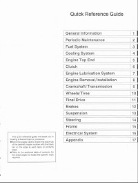
Руководство на английском языке по техническому обслуживанию и ремонту мотоциклов Kawasaki Ninja ZX-6R и ZX-6RR 2003-2004 годов выпуска.
- Издательство: Kawasaki Heavy Industries, Ltd.
- Год издания: —
- Страниц: 514
- Формат: PDF
- Размер: 42,5 Mb

Руководство на английском языке по техническому обслуживанию и ремонту мотоциклов Kawasaki Ninja ZX-6RR.
- Издательство: Kawasaki Heavy Industries, Ltd.
- Год издания: 2004
- Страниц: 519
- Формат: PDF
- Размер: 10,1 Mb
Руководство на английском языке по подготовке к гонкам мотоциклов Kawasaki ZX-6RR.
- Издательство: Kawasaki Heavy Industries, Ltd.
- Год издания: 2005
- Страниц: 63
- Формат: PDF
- Размер: 7,5 Mb
Руководство на английском языке по техническому обслуживанию и ремонту мотоциклов Kawasaki Ninja ZX-7R и ZX-7RR.
- Издательство: Kawasaki Heavy Industries, Ltd.
- Год издания: —
- Страниц: 364
- Формат: PDF
- Размер: 38,7 Mb
Руководство на английском языке по подготовке к гонкам мотоциклов Kawasaki ZX-7R м ZXR750R 1992 года выпуска.
- Издательство: Kawasaki Heavy Industries, Ltd.
- Год издания: 1991
- Страниц: 69
- Формат: PDF
- Размер: 148,4 Mb
Руководство на английском языке по подготовке к гонкам мотоциклов Kawasaki ZX-7RR 1998 года выпуска.
- Издательство: Kawasaki Heavy Industries, Ltd.
- Год издания: 1997
- Страниц: 107
- Формат: PDF
- Размер: 138,0 Mb

Руководство на испанском языке по эксплуатации и техническому обслуживанию мотоциклов Kawasaki Ninja ZX-9R.
- Издательство: —
- Год издания: —
- Страниц: 174
- Формат: PDF
- Размер: 3,3 Mb
Сборник руководств на английском языке по техническому обслуживанию и ремонту мотоциклов Kawasaki Ninja ZX-9R.
- Издательство: Kawasaki Heavy Industries, Ltd.
- Год издания: —
- Страниц: 307/322
- Формат: PDF
- Размер: 161,3 Mb
Руководство на английском языке по техническому обслуживанию и ремонту мотоциклов Kawasaki ZX-10 и Ninja ZX-10.
- Издательство: Kawasaki Heavy Industries, Ltd.
- Год издания: 1989
- Страниц: 231
- Формат: PDF
- Размер: 162,0 Mb

Руководство на английском языке по техническому обслуживанию и ремонту мотоциклов Kawasaki Ninja ZX-10R.
- Издательство: Kawasaki Heavy Industries, Ltd.
- Год издания: 2008
- Страниц: 694
- Формат: PDF
- Размер: 14,7 Mb
Руководство на английском языке по подготовке к гонкам мотоциклов Kawasaki ZX-10R 2006 года выпуска.
- Издательство: Kawasaki Heavy Industries, Ltd.
- Год издания: 2006
- Страниц: 82
- Формат: PDF
- Размер: 2,5 Mb

Руководство по эксплуатации и техническому обслуживанию мотоциклов Kawasaki Ninja ZX-10R.
- Издательство: Kawasaki Heavy Industries, Ltd.
- Год издания: 2011
- Страниц: 207
- Формат: PDF
- Размер: 6,4 Mb

Руководство на английском языке по техническому обслуживанию и ремонту мотоциклов Kawasaki Ninja ZX-11 и ZZ-R1100 1993-2001 годов выпуска.
- Издательство: Kawasaki Heavy Industries, Ltd.
- Год издания: —
- Страниц: —
- Формат: JPG
- Размер: 62,4 Mb
Руководство на английском языке по техническому обслуживанию и ремонту мотоциклов Kawasaki Ninja ZX-12R.
- Издательство: Kawasaki Heavy Industries, Ltd.
- Год издания: 2004
- Страниц: 613
- Формат: PDF
- Размер: 11,3 Mb

Руководство на немецком языке по техническому обслуживанию и ремонту мотоциклов Kawasaki Ninja ZX-12R (ZX1200-A).
- Издательство: Kawasaki Motoren GmbH
- Год издания: 2000
- Страниц: 431
- Формат: PDF
- Размер: 149,8 Mb

Руководство на немецком языке по техническому обслуживанию и ремонту мотоциклов Kawasaki ZX-12R (ZX1200B).
- Издательство: Kawasaki Motors Europe
- Год издания: 2002
- Страниц: 451
- Формат: PDF
- Размер: 38,7 Mb

Руководство на английском языке по техническому обслуживанию и ремонту мотоциклов Kawasaki Ninja ZX-14 и ZZR1400.
- Издательство: Kawasaki Heavy Industries, Ltd.
- Год издания: 2006
- Страниц: 703
- Формат: PDF
- Размер: 13,6 Mb
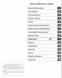
Руководство на английском языке по техническому обслуживанию и ремонту мотоциклов Kawasaki ZX400-H2
- Издательство: Kawasaki Heavy Industries, Ltd.
- Год издания: —
- Страниц: —
- Формат: PDF
- Размер: 46,6 Mb

Руководство на немецком языке по техническому обслуживанию и ремонту мотоциклов Kawasaki ZX500-A1 и ZX600-A1.
- Издательство: —
- Год издания: —
- Страниц: 234
- Формат: PDF
- Размер: 19,9 Mb

Руководство на английском языке по техническому обслуживанию и ремонту мотоциклов Kawasaki KZ500/KZ550/ZX550 1979-1985 годов выпуска.
- Издательство: Clymer
- Год издания: —
- Страниц: 341
- Формат: PDF
- Размер: 12,0 Mb
Руководство на английском языке по техническому обслуживанию и ремонту мотоциклов Kawasaki ZX600/ZZR600/Ninja ZX-6 1990-2000 годов выпуска.
- Издательство: Haynes Publishing
- Год издания: 2001
- Страниц: —
- Формат: JPG
- Размер: 57,7 Mb

Руководство на английском языке по техническому обслуживанию и ремонту мотоциклов Kawasaki ZX600/ZX636 (ZX-6R) 1995-2002 годов выпуска.
- Издательство: Haynes Publishing
- Год издания: 2003
- Страниц: 272
- Формат: PDF
- Размер: 171,0 Mb
Руководство на английском языке по техническому обслуживанию и ремонту мотоциклов Kawasaki GPX600R/GPX750R/GPZ600R/Ninja 600R/Ninja 600RX/Ninja 750R/ZX600/ZX750 1985-1987 годов выпуска.
- Издательство: Haynes Publishing
- Год издания: 1999
- Страниц: 265
- Формат: PDF
- Размер: 77,0 Mb

Руководство на английском языке по техническому обслуживанию и ремонту мотоциклов Kawasaki ZX750 (ZXR750) 1989-1996 и ZX750 (Ninja ZX-7) 1989-1995 годов выпуска.
- Издательство: Haynes Publishing
- Год издания: 1998
- Страниц: 341
- Формат: PDF
- Размер: 36,7 Mb

Руководство на немецком языке по техническому обслуживанию и ремонту мотоциклов Kawasaki ZX750J/ZX750K/ZXR750/ZXR750R.
- Издательство: —
- Год издания: —
- Страниц: 282
- Формат: PDF
- Размер: 23,4 Mb
Руководство на немецком языке по техническому обслуживанию и ремонту мотоциклов Kawasaki GPX750R/ZX750F.
- Издательство: Kawasaki Heavy Industries, Ltd.
- Год издания: —
- Страниц: 192
- Формат: PDF
- Размер: 11,4 Mb
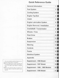
Руководство на английском языке по техническому обслуживанию и ремонту мотоциклов Kawasaki ZX900-A1.
- Издательство: Kawasaki Heavy Industries, Ltd.
- Год издания: —
- Страниц: 293
- Формат: PDF
- Размер: 22,9 Mb
Руководство на английском языке по техническому обслуживанию и ремонту мотоциклов Kawasaki ZX900-C1 и ZX900-D1.
- Издательство: Kawasaki Heavy Industries, Ltd.
- Год издания: —
- Страниц: 307
- Формат: PDF
- Размер: 27,9 Mb
Руководство на немецком языке по техническому обслуживанию и ремонту мотоциклов Kawasaki GPZ1000RX (ZX1000-A1).
- Издательство: Kawasaki Heavy Industries, Ltd.
- Год издания: —
- Страниц: 130
- Формат: PDF
- Размер: 20,8 Mb
Руководство на немецком языке по техническому обслуживанию и ремонту мотоциклов Kawasaki GPZ1100 (ZX1100E).
- Издательство: Kawasaki Heavy Industries, Ltd.
- Год издания: —
- Страниц: 327
- Формат: PDF
- Размер: 10,9 Mb

-
Contents
-
Table of Contents
-
Troubleshooting
-
Bookmarks
Related Manuals for Yamaha XVS1100(L)
Summary of Contents for Yamaha XVS1100(L)
-
Page 2
EB000000 XVS1100 (L) SERVICE MANUAL 1998 by Yamaha Motor Co.,Ltd. First edition, October 1998 All rights reserved. Any reproduction or unauthorized use without the written permission of Yamaha Motor Co., Ltd. is expressly prohibited. -
Page 3
It is not possible to include all the knowledge of a mechanic in one manual, so it is assumed that anyone who uses this book to perform maintenance and repairs on Yamaha mo- torcycles has a basic understanding of the mechanical ideas and the procedures of motorcycle repair. -
Page 4: How To Use This Manual
EB002000 HOW TO USE THIS MANUAL MANUAL ORGANIZATION This manual consists of chapters for the main categories of subjects. (See “Illustrated symbols”) 1st title 1 : This is the title of the chapter with its symbol in the upper right corner of each page. 2nd title 2 : This title indicates the section of the chapter and only appears on the first page of each section.
-
Page 5
EB003000 ILLUSTRATED SYMBOLS Illustrated symbols 1 to 9 are printed on the top right of each page and indicate the subject of each chapter. 1 General information 2 Specifications 3 Periodic inspections and adjustments 4 Engine 5 Cooling system 6 Carburetion 7 Chassis 8 Electrical 9 Troubleshooting… -
Page 6
CHAPTER TITLES GENERAL INFORMATION INFO SPECIFICATIONS SPEC PERIODIC INSPECTION AND INSP ADJUSTMENTS ENGINE OVERHAUL CARBURETION CARB CHASSIS CHAS ELECTRICAL ELEC TROUBLESHOOTING TRBL SHTG… -
Page 7
INFO… -
Page 8: Table Of Contents
INFO CHAPTER 1. GENERAL INFORMATION MOTORCYCLE IDENTIFICATION ……. VEHICLE IDENTIFICATION NUMBER .
-
Page 9: General Information
MOTORCYCLE IDENTIFICATION INFO EB100000 GENERAL INFORMATION MOTORCYCLE IDENTIFICATION EB100010 VEHICLE IDENTIFICATION NUMBER The vehicle identification number 1 is stamped into the right side of the steering head. MODEL LABEL The model label 1 is affixed to the frame. This information will be needed to order spare parts.
-
Page 10: Important Information
5. Keep all parts away from any source of fire. EB101010 REPLACEMENT PARTS 1. Use only genuine Yamaha parts for all re- placements. Use oil and grease recom- mended by Yamaha for all lubrication jobs. Other brands may be similar in function and appearance, but inferior in quality.
-
Page 11: Lock Washers/Plates And Cotter Pins
IMPORTANT INFORMATION INFO EB101030 LOCK WASHERS/PLATES AND COTTER PINS 1. Replace all lock washers/plates 1 and cot- ter pins after removal. Bend lock tabs along the bolt or nut flats after the bolt or nut has been tightened to specification. EB101040 BEARINGS AND OIL SEALS 1.
-
Page 12: Checking Of Connections
CHECKING OF CONNECTIONS INFO EB801000 CHECKING OF CONNECTIONS Check the connectors for stains, rust, moisture, etc. 1. Disconnect: S Connector 2. Check: S Connector Moisture ! Dry each terminal with an air blower. Stains/rust ! Connect and disconnect the terminals several times. 3.
-
Page 13: Special Tools
SPECIAL TOOLS INFO EB102001 SPECIAL TOOLS The following special tools are necessary for complete and accurate tune-up and assembly. Use only the appropriate special tools; this will help prevent damage caused by the use of inappropriate tools or improvised techniques. Special tools may differ by shape and part number from country to country. In such a case, two types are provided.
-
Page 14
SPECIAL TOOLS INFO Tool No. Tool name/How to use Illustration T-handle/damper rod holder T-handle 90890-01326 Holder These tools are needed to loosen and tighten 90890-01460 the damper rod holding bolt. Flywheel puller/adapter Puller 90890-01362 Adapter 90890-04131 These tools are needed to remove the rotor. Fork seal driver weight/adapter Weight 90890-01367… -
Page 15
SPECIAL TOOLS INFO Tool No. Tool name/How to use Illustration Timing light 90890-03141 This tool is necessary for checking ignition timing. Valve guide remover & installer 90890-04014 This tool is needed to remove and install the valve guide. Valve spring compressor 90890-04019 This tool is needed to remove and install the valve assemblies. -
Page 16
This tool is needed when removing or instal- ling the damper spring. Dynamic spark tester Ignition checker 90890-06754 This instrument is necessary for checking the ignition system components. Yamaha bond No.1215 90890-85505 This sealant (bond) is used on crankcase mat- ing surfaces, etc. -
Page 17
SPEC… -
Page 18
SPEC CHAPTER 2. SPECIFICATIONS GENERAL SPECIFICATIONS ……..MAINTENANCE SPECIFICATIONS . -
Page 19: Chapter 2. Specifications
SPEC GENERAL SPECIFICATIONS SPECIFICATIONS GENERAL SPECIFICATIONS Item Standard Model code: XVS1100: 5EL1 (For Europe) 5EL2 (For D, A, FIN) 5EL3 (For Australia) Dimensions: Overall length 2,405 mm Overall width 895 mm Overall height 1,095 mm Seat height 690 mm Wheelbase 1,640 mm Minimum ground clearance 145 mm…
-
Page 20
SPEC GENERAL SPECIFICATIONS Item Standard Carburetor: Type/quantity BSR37/2 Manufacturer MIKUNI Spark plug: Type BPR7ES/W22EPR–U Manufacturer NGK/DENSO 0.7 X 0.8 mm Spark plug gap Clutch type: Wet, multiple-disc Transmission: Primary reduction system Spur gear Primary reduction ratio 78/47 (1.660) Secondary reduction system Shaft drive Secondary reduction ratio 44/47… -
Page 21
SPEC GENERAL SPECIFICATIONS Item Standard Suspension: Front suspension Telescopic fork Rear suspension Swingarm (link suspension) Shock absorber: Front shock absorber Coil spring/Oil damper Rear shock absorber Coil spring/Gas-oil damper Wheel travel: Front wheel travel 140 mm Rear wheel travel 113 mm Electrical: Ignition system T.C.I. -
Page 22: Maintenance Specifications
SPEC MAINTENANCE SPECIFICATIONS MAINTENANCE SPECIFICATIONS ENGINE Item Standard Limit Cylinder head: Warp limit 0.03 mm Cylinder: 95.00 X 95.01 mm Bore size 95.1 mm Measuring point 40 mm Camshaft: Drive method Chain drive (left & right) 25.000 X 25.021 mm Cam cap inside diameter 24.96 X 24.98 mm Camshaft outside diameter…
-
Page 23
SPEC MAINTENANCE SPECIFICATIONS Item Standard Limit Timing chain: Timing chain type/No. of links SILENT CHAIN/98L Timing chain adjustment method Automatic Rocker arm/rocker arm shaft: 14.000 mm X 14.018 mm Bearing inside diameter 14.036 mm 13.985 mm X 13.991 mm Shaft outside diameter 13.95 mm 0.009 mm X 0.033 mm Arm-to-shaft clearance… -
Page 24
SPEC MAINTENANCE SPECIFICATIONS Item Standard Limit Stem runout limit 0.03 mm 1.2 X 1.4 mm Valve seat width 2.0 mm 1.2 X 1.4 mm 2.0 mm Valve spring: Free length 44.6 mm 43.5 mm 44.6 mm 43.5 mm Set length (valve closed) 40 mm 40 mm Compressed pressure… -
Page 25
SPEC MAINTENANCE SPECIFICATIONS Item Standard Limit 22.004 X 22.015 mm Piston pin bore inside diameter 21.991 X 22.000 mm Piston pin outside diameter Piston rings: Top ring: Type Plain Dimensions (B 3.8 mm 0.3 X 0.5 mm End gap (installed) 0.8 mm 0.04 X 0.08 mm Side clearance (installed) -
Page 26
SPEC MAINTENANCE SPECIFICATIONS Item Standard Limit Clutch: 2.9 X 3.1 mm Friction plate thickness 2.8 mm Quantity 2.5 X 2.7 mm Clutch plate thickness 0.1 mm Quantity 1.9 X 2.1 mm Clutch plate thickness 0.1 mm Quantity Clutch spring free length 7.2 mm 6.5 mm Quantity… -
Page 27
SPEC MAINTENANCE SPECIFICATIONS Item Standard Limit Lubrication system: Oil filter type Paper type Oil pump type Trochoid type 0.03 X 0.09 mm Tip clearance “A” or “B” 0.15 mm 0.03 X 0.08 mm 0.15 mm Side clearance 450 X 550 kPa (4.5 X 5.5 kg/cm Relief valve operating pressure Shaft drive: 0.1 X 0.2 mm… -
Page 28
SPEC MAINTENANCE SPECIFICATIONS Item Standard Lubrication chart: 2-10… -
Page 29
SPEC MAINTENANCE SPECIFICATIONS Cylinder head tightening sequence: Crankcase tightening sequence: Left crankcase Right crankcase 2-11… -
Page 30
SPEC MAINTENANCE SPECIFICATIONS Tightening torques Tightening Thread torque Part to be tightened Part name Q’ty Remarks size size mSkg Cylinder head Cylinder head Plate Bolt Cylinder head cover Screw Cylinder head (exhaust pipe) Stud bolt 12.5 1.25 Rocker arm shaft Union bolt 37.5 3.75… -
Page 31
SPEC MAINTENANCE SPECIFICATIONS Tightening Thread torque Part to be tightened Part name Q’ty Remarks size size mSkg Clutch spring Bolt Clutch adjuster Clutch boss Use lock washer Push lever axle Screw Stake Middle drive pinion gear 11.0 Stake Bearing retainer (middle driven shaft) 11.0 Stake Yoke (middle driven shaft) -
Page 32: Chassis
SPEC MAINTENANCE SPECIFICATIONS CHASSIS Item Standard Limit Steering system: Steering bearing type Angular bearing Front suspension: Front fork travel 140 mm Fork spring free length 356.9 mm 350 mm Fitting length 319.4 mm Collar length 183 mm Spring rate (K1) 8.8 N/mm (0.9 kg/mm) (K2) 12.7 N/mm (1.3 kg/mm)
-
Page 33
SPEC MAINTENANCE SPECIFICATIONS Item Standard Limit Front brake: Type Dual disc Disc outside diameter thickness 5 mm 4.5 mm Disc deflection limit 0.15 mm Pad thickness inner 6.2 mm 0.8 mm Pad thickness outer 6.2 mm 0.8 mm Master cylinder inside diameter 14.0 mm Caliper cylinder inside diameter 25.4 mm… -
Page 34
SPEC MAINTENANCE SPECIFICATIONS Tightening torques Tightening torque Part to be tightened Thread size Remarks mSkg Upper bracket and inner tube Lower bracket and inner tube Upper bracket and steering shaft 11.0 Ring nut (steering shaft) — See NOTE Handlebar holder (lower) and upper bracket Handlebar holder (lower) and handlebar holder (upper) Master cylinder (front brake) -
Page 35
SPEC MAINTENANCE SPECIFICATIONS Tightening Thread torque Part to be tightened Remarks size size mSkg Passenger footrest and frame Sidestand bracket and frame Sidestand and sidestand bracket Sidestand switch Brake pedal/footrest and frame Rear brake master cylinder and master cylinder bracket Master cylinder bracket and down tube Footrest and frame Front wheel axle… -
Page 36: Electrical
SPEC MAINTENANCE SPECIFICATIONS ELECTRICAL Item Standard Limit Voltage: 12 V Ignition system: Ignition timing (B.T.D.C.) 10_ at 1,000 r/min Advancer type Digital type T.C.I.: 189 X 231 Ω at 20_C/Gray – Black Pickup coil resistance/color T.C.I. unit model/manufacturer J4T101/MITSUBISHI Ignition coil: Model/manufacturer F6T507 /MITSUBISHI 3.57 X 4.83 Ω…
-
Page 37
SPEC MAINTENANCE SPECIFICATIONS Item Standard Limit Horn: Type Plane type Quantity Model/manufacturer YF-12/NIKKO Maximum amperage Flasher relay: Type Full transistor type Model/manufacturer FE246BH/DENSO Self cancelling device 75 X 95 cycle/min Flasher frequency Wattage 21 W 2 + 3.4W Oil level gauge: Model/manufacturer 5EL/DENSO Starting circuit cut-off relay… -
Page 38: General Torque Specifications
GENERAL TORQUE SPECIFICATIONS SPEC /CONVERSION TABLE EB202001 EAS00028 GENERAL TORQUE CONVERSION TABLE SPECIFICATIONS All specification data in this manual are listed in SI and METRIC UNITS. This chart specifies torque for standard fasten- Use this table to convert METRIC unit data to ers with standard I.S.O.
-
Page 39: Lubrication Points And Lubricant Types
SPEC LUBRICATION POINTS AND LUBRICANT TYPES EB203000 LUBRICATION POINTS AND LUBRICANT TYPES ENGINE Lubrication point Symbol Oil seal lips O-ring Bearing Connecting rod bolt/nut Connecting rod small end and big end Crankshaft pin Crankshaft journal/big end Piston surface Piston pin Camshaft cam lobe/journal Rocker arm shaft Valve stem (IN, EX)
-
Page 40: Chassis
SPEC LUBRICATION POINTS AND LUBRICANT TYPES EB203010 CHASSIS Lubrication point Symbol Steering head pipe (upper/lower), bearing Steering head pipe, bearing cover lip Steering head pipe, oil seal lip Front wheel oil seal lip (right/left) Rear wheel oil seal lip Clutch hub fitting area Rear brake pedal shaft Shift pedal shaft Sidestand bolt, sidestand sliding surface…
-
Page 41: Lubrication Diagrams
SPEC LUBRICATION DIAGRAMS EB205000 LUBRICATION DIAGRAMS Rocker arm shaft (intake) Oil pump Rocker arm shaft (exhaust) Drive axle Oil filter Middle drive shaft 2-23…
-
Page 42
SPEC LUBRICATION DIAGRAMS Oil pump Middle drive shaft Releaf valve Oil filter 2-24… -
Page 43
SPEC LUBRICATION DIAGRAMS Camshaft Middle drive shaft Crankshaft Drive axle Main axle Connecting rod big end 2-25… -
Page 44
SPEC CABLE ROUTING EB206000 CABLE ROUTING Clutch cable Alarm connector Fuel hose (carburetor-fuel pump) Starter cable Fuel pump lead Brake hose Handlebar switch lead (left) Speed sensor lead Heat protector Handlebar switch lead (right) Sidestand switch lead Fuel breather hose (fuel tank- High tension code Neutral switch lead roll over valve) (for California) -
Page 45: Cable Routing
SPEC CABLE ROUTING Purge hose (carburetor-solenoid B Position the throttle cable and F Push the wire harness inside valve) (for California) starter cable as shown, and of the tool box plate. A Fasten the handlebar switch clamp them with holder. G Route the sidestand lead leads (left and right) to the C Clamp the wire harness with…
-
Page 46
SPEC CABLE ROUTING J Fasten the handlebar switch M Fasten the AC magneto lead leads (left and right) under the and sidestand switch lead with a handle crown with a plastic plastic locking tie. band. N Fasten the alarm lead with a Set the band at four notches, plastic band on the lid. -
Page 47
SPEC CABLE ROUTING Battery Ignition coil Handlebar switch lead (left) Battery positive (+) lead Master cylinder reservoir hose Throttle position sensor lead Starter motor positive (+) lead Breather hose Carburetor heater lead Speedometer lead Air filter drain hose Thermo switch lead Fuel hose (carburetor-fuel pump) Battery negative (–) lead Starting circuit cutoff relay… -
Page 48
SPEC CABLE ROUTING A Clamp the battery positive (+) D Connect the purge hose H Fasten the rear brake switch lead to the battery with battery (carburetor side-solenoid valve lead and master cylinder band. side) with joint. (for California) reservoir hose to the down B Connect the battery negative E Route the front turn signal light tube with a plastic locking tie. -
Page 49
SPEC CABLE ROUTING K To rear brake caliper L Clamp the handlebar switch lead (right) and main switch lead to the frame with a holder. M Arrange the throttle position sensor connector, carburetor heater connector and thermo switch connector between the starting circuit cutoff relay and high tension code. -
Page 50
SPEC CABLE ROUTING Brake hose Battery negative (–) lead Starter cable Throttle cable connector Fuel hose (fuel cock-fuel filter) Master cylinder reservoir hose Battery Carburetor heater lead High tension code Battery positive (+) lead Thermo switch lead Purge hose (carburetor-solenoid Taillight lead Igniter unit valve) (for California) -
Page 51
SPEC CABLE ROUTING B Route the rear brake switch F Route the battery positive (+) J Fasten the wire harness with a lead under the master cylinder lead through the slit of the band on the tool box plate. reservoir hose. battery box. -
Page 52
SPEC CABLE ROUTING L Route wire harness outside of P Route the igniter lead through the guide on the frame. the igniter plate hole to the wire M Clamp the clutch cable and harness. starter cable with a holder. Q Clamp the taillight lead with Position the end of holder down mud guard clamp. -
Page 53
SPEC CABLE ROUTING Throttle cable Starter cable Clutch cable Handlebar switch lead (left) Headlight lead Brake hose A Route the handlebar switch lead (right) rear side of the throttle cable. 2-35… -
Page 54
INSP… -
Page 55
INSP CHAPTER 3 PERIODIC INSPECTIONS AND ADJUSTMENTS INTRODUCTION ……….PERIODIC MAINTENANCE/LUBRICATION INTERVALS . -
Page 56
INSP ELECTRICAL SYSTEM ……… 3-37 CHECKING AND CHARGING THE BATTERY . -
Page 57: Periodic Inspections And Adjustments
INTRODUCTION/PERIODIC MAINTENANCE/ INSP LUBRICATION INTERVALS EB300000 PERIODIC INSPECTIONS AND ADJUSTMENTS INTRODUCTION This chapter includes all information necessary to perform recommended inspections and adjust- ments. These preventive maintenance procedures, if followed, will ensure more reliable vehicle opera- tion and a longer service life. The need for costly overhaul work will be greatly reduced. This informa- tion applies to vehicles already in service as well as to new vehicles that are being prepared for sale.
-
Page 58
Final gear oil 24,000 km or 24 months (whichever comes first). * Since these items require special tools, data and technical skills, they should be serviced by a Yamaha dealer. NOTE: S The air filter needs more frequent service if you are riding in unusually wet or dusty areas. -
Page 59: Fuel Tank And Seats
INSP FUEL TANK AND SEATS FUEL TANK AND SEATS 23Nm (2.3mSkg) 7 Nm (0.7mSkg) 7 Nm (0.7mSkg) Order Job name/Part name Q’ty Remarks Fuel tank and seats removal Remove the parts in the order below. Passenger seat Seat bracket Rider’s seat Fuel hose NOTE: Set the fuel cock to “OFF”…
-
Page 60: Removal
INSP FUEL TANK AND SEATS REMOVAL 1. Remove: S Ignitor plate NOTE: To remove the quick fastener, push its center in with a screwdriver, then pull the fastener out. INSTALLATION 1. Install: S Ignitor plate NOTE: To install the quick fastener, push its pin so that it protrudes from the fastener head, then insert the fastener into the cowling and push the pin a in with a screwdriver.
-
Page 61: Engine
INSP ADJUSTING THE VALVE CLEARANCE EAS00047 ENGINE ADJUSTING THE VALVE CLEARANCE The following procedure applies to all of the valves. NOTE: S Valve clearance adjustment should be made on a cold engine, at room temperature. S When the valve clearance is to be measured or adjusted, the piston must be at top dead center (TDC) on the compression stroke.
-
Page 62
INSP ADJUSTING THE VALVE CLEARANCE 6. Remove: S tappet covers 1 7. Remove: S camshaft sprocket cover (rear cylinder) 1 S camshaft sprocket cover (front cylinder) 8. Remove: S timing plug 1 S straight plug 2 9. Measure: S valve clearance Out of specification ! Adjust. -
Page 63
INSP ADJUSTING THE VALVE CLEARANCE a. Turn the crankshaft counterclockwise. b. When the piston is at TDC on the compres- sion stroke, align either the camshaft sprock- et plate hole a with the stationary pointer b on the cylinder head. When the camshaft sprocket plate hole or camshaft sprocket punch mark is aligned with the stationary pointer, the piston is at top dead center… -
Page 64: Synchronizing The Carburetors
ADJUSTING THE VALVE CLEARANCE/ INSP SYNCHRONIZING THE CARBURETORS Locknut: 27 Nm (2.7 mSkg) e. Measure the valve clearance again. f. If the valve clearance is still out of specifica- tion, repeat all of the valve clearance adjust- ment steps until the specified clearance is obtained.
-
Page 65
INSP SYNCHRONIZING THE CARBURETORS 5. Install: S vacuum gauge 1 S engine tachometer 2 (to the spark plug lead of cyl. #2) Vacuum gauge: 90890-03094 Engine tachometer: 90890-03113 6. Start the engine and let it warm up for several minutes. 7. -
Page 66: Adjusting The Engine Idling Speed
SYNCHRONIZING THE CARBURETORS/ INSP ADJUSTING THE ENGINE IDLING SPEED Throttle cable free play (at the flange of the throttle grip) 4 X 6 mm 12. Install: S vacuum plugs S air duct S fuel tank S seat EAS00054 ADJUSTING THE ENGINE IDLING SPEED NOTE: Prior to adjusting the engine idling speed, the carburetor synchronization should be adjusted…
-
Page 67: Adjusting The Throttle Cable Free Play
ADJUSTING THE ENGINE IDLING SPEED/ INSP ADJUSTING THE THROTTLE CABLE FREE PLAY 6. Adjust: S throttle cable free play Refer to “ADJUSTING THE THROTTLE CABLE FREE PLAY”. Throttle cable free play (at the flange of the throttle grip) 4 X 6 mm EAS00058 ADJUSTING THE THROTTLE CABLE FREE PLAY…
-
Page 68: Checking The Spark Plugs
ADJUSTING THE THROTTLE CABLE FREE PLAY/ INSP CHECKING THE SPARK PLUGS Handlebar side a. Loosen the locknut 1 . b. Turn the adjusting nut 2 in direction a or b until the specified throttle cable free play is obtained. Throttle cable free play is Direction increased.
-
Page 69: Checking The Ignition Timing
CHECKING THE SPARK PLUGS/ INSP CHECKING THE IGNITION TIMING 7. Measure: S spark plug gap a (with a wire gauge) Out of specification ! Regap. Spark plug gap 0.7 X 0.8 mm 8. Install: S spark plug 20 Nm (2.0 mSkg) NOTE: Before installing the spark plug, clean the spark plug and gasket surface.
-
Page 70: Measuring The Compression Pressure
CHECKING THE IGNITION TIMING/ INSP MEASURING THE COMPRESSION PRESSURE 3. Check: S ignition timing a. Start the engine, warm it up for several min- utes, and then let it run at the specified en- gine idling speed. Engine idling speed: 950 X 1,050 r/min b.
-
Page 71
INSP MEASURING THE COMPRESSION PRESSURE CAUTION: Before removing the spark plugs, use com- pressed air to blow away any dirt accumu- lated in the spark plug wells to prevent it from falling into the cylinders. 5. Install: S compression gauge 1 Compression gauge set: 90890-03081 6. -
Page 72: Checking The Engine Oil Level
MEASURING THE COMPRESSION PRESSURE/ INSP CHECKING THE ENGINE OIL LEVEL 7. Install: S spark plug 20 Nm (2.0 mSkg) 8. Connect: S spark plug cap EAS00069 CHECKING THE ENGINE OIL LEVEL 1. Stand the motorcycle on a level surface. NOTE: S Place the motorcycle on a suitable stand.
-
Page 73: Changing The Engine Oil
CHECKING THE ENGINE OIL LEVEL/ INSP CHANGING THE ENGINE OIL 4. Start the engine, warm it up for several min- utes, and then turn it off. 5. Check the engine oil level again. NOTE: Before checking the engine oil level, wait a few minutes until the oil has settled.
-
Page 74: Adjusting The Clutch Cable Free Play
CHANGING THE ENGINE OIL/ INSP ADJUSTING THE CLUTCH CABLE FREE PLAY Quantity Total amount 3.6 L Without oil filter element replacement 3.0 L With oil filter element replacement 3.1 L 9. Install: S o-ring S engine oil filter cap 10. Start the engine, warm it up for several min- utes, and then turn it off.
-
Page 75: Cleaning The Air Filter Element
ADJUSTING THE CLUTCH CABLE FREE PLAY/ INSP CLEANING THE AIR FILTER ELEMENT 4. Adjust: S clutch mechanism Engine side a. Loosen the locknut 1 . b. Turn in the adjusting screw 2 until it is lightly seated. c. Turn the adjusting screw out 1/4 of a turn. d.
-
Page 76: Checking The Carburetor Joint And Intake Manifold
CLEANING THE AIR FILTER ELEMENT / INSP CHECKING THE CARBURETOR JOINT AND INTAKE MANIFOLD / CHECKING THE BREATHER HOSE CAUTION: Never operate the engine without the air filter element installed. Unfiltered air will cause rapid wear of engine parts and may damage the engine.
-
Page 77: Checking The Exhaust System
INSP CHECKING THE EXHAUST SYSTEM EAS00100 CHECKING THE EXHAUST SYSTEM The following procedure applies to all of the ex- haust pipes, mufflers and gaskets. 1. Check: S exhaust pipes 1 S muffler 2 Cracks/damage ! Replace. S gaskets 3 Exhaust gas leaks ! Replace. 2.
-
Page 78: Chassis
INSP ADJUSTING THE FRONT BRAKE EAS00108 CHASSIS ADJUSTING THE FRONT BRAKE 1. Check: S brake lever free play a Out of specification ! Adjust. Brake lever free play (at the end of the brake lever) 5 X 8 mm 2. Adjust: S brake lever free play a.
-
Page 79: Adjusting The Rear Brake
INSP ADJUSTING THE REAR BRAKE EAS00110 ADJUSTING THE REAR BRAKE 1. Check: S brake pedal position (distance a from the top of the rider footrest to the top of the brake pedal) Out of specification ! Adjust. Brake pedal position (below the top of the rider footrest) 81.8 mm 2.
-
Page 80: Checking The Brake Fluid Level
INSP CHECKING THE BRAKE FLUID LEVEL EAS00115 CHECKING THE BRAKE FLUID LEVEL 1. Stand the motorcycle on a level surface. NOTE: S Place the motorcycle on a suitable stand. S Make sure that the motorcycle is upright. 2. Check; S brake fluid level Below the minimum level mark a ! Add the recommended brake fluid to the proper level.
-
Page 81: Adjusting The Rear Brake Light Switch
ADJUSTING THE REAR BRAKE LIGHT SWITCH/ INSP CHECKING THE BRAKE HOSES EAS00128 ADJUSTING THE REAR BRAKE LIGHT SWITCH NOTE: The rear brake light switch is operated by move- ment of the brake pedal. The rear brake light switch is properly adjusted when the brake light comes on just before the braking effect starts.
-
Page 82: Bleeding The Hydraulic Brake System
INSP BLEEDING THE HYDRAULIC BRAKE SYSTEM EAS00134 BLEEDING THE HYDRAULIC BRAKE SYS- WARNING Bleed the hydraulic brake system whenever: S the system was disassembled, S a brake hose was loosened or removed, S the brake fluid level is very low, S brake operation is faulty.
-
Page 83: Adjusting The Shift Pedal
BLEEDING THE HYDRAULIC BRAKE SYSTEM/ INSP ADJUSTING THE SHIFT PEDAL h. Tighten the bleed screw and then release the brake lever or brake pedal. i. Repeat steps (e) to (h) until all of the air bubbles have disappeared from the brake fluid in the plastic hose.
-
Page 84: Checking The Final Drive Oil Level
CHECKING THE FINAL DRIVE OIL LEVEL/ INSP CHANGING THE FINAL DRIVE OIL EAS00144 CHECKING THE FINAL DRIVE OIL LEVEL 1. Stand the motorcycle on a level surface. NOTE: S Place the motorcycle on a suitable stand. S Make sure that the motorcycle is upright. 2.
-
Page 85: Checking And Adjusting The Steering Head
CHANGING THE FINAL DRIVE OIL/ INSP CHECKING AND ADJUSTING THE STEERING HEAD Quantity 0.2 L Refer to “CHECKING THE FINAL DRIVE OIL LEVEL”. EAS00146 CHECKING AND ADJUSTING THE STEER- ING HEAD 1. Stand the motorcycle on a level surface. WARNING Securely support the motorcycle so that there is no danger of it falling over.
-
Page 86
INSP CHECKING AND ADJUSTING THE STEERING HEAD b. Loosen the lower ring nut 4 and then tighten it to specification with a ring nut wrench 5 . NOTE: Set the torque wrench at a right angle to the ring nut wrench. Ring nut wrench 90890-01403 Lower ring nut (initial tightening… -
Page 87: Checking The Front Fork
CHECKING THE FRONT FORK/ INSP ADJUSTING THE REAR SHOCK ABSORBER ASSEMBLY EAS00149 CHECKING THE FRONT FORK 1. Stand the motorcycle on a level surface. WARNING Securely support the motorcycle so that there is no danger of it falling over. 2. Check: S inner tube Damage/scratches ! Replace.
-
Page 88: Checking The Tires
ADJUSTING THE REAR SHOCK ABSORBER ASSEMBLY/ INSP CHECKING THE TIRES Ring nut wrench 1HX-28135-00 a. Turn the adjusting knob 1 in direction a or ! Spring preload is Direction increased (suspension is harder). ! Spring preload is Direction decreased (suspension is softer). Adjusting position Standard: 3 Minimum: 1 (soft)
-
Page 89
INSP CHECKING THE TIRES Basic weight: (with 274 kg oil and full fuel tank) Maximum 201 kg load*: Cold tire Front Rear pressure: Up to 90 kg 200 kPa 225 kPa load* (2.00 kgf/cm (2.25 kgf/cm 90 kg 225 kPa 250 kPa X maximum (2.25 kgf/cm… -
Page 90
No guarantee concerning handling characteristics can be given if a tire combination other than one approved by Yamaha is used on this motorcycle. Front tire: Manufactur- Type… -
Page 91: Checking And Tightening The Spokes
CHECKING THE TIRES/ INSP CHECKING AND TIGHTENING THE SPOKES NOTE: For tires with a direction of rotation mark 1 : S Install the tire with the mark pointing in the direction of wheel rotation. S Align the mark 2 with the valve installation point.
-
Page 92: Checking And Lubricating The Cables
CHECKING AND LUBRICATING THE CABLES / INSP LUBRICATING THE LEVERS AND PEDALS / LUBRICATING THE SIDESTAND/ LUBRICATING THE REAR SUSPENSION EAS00170 CHECKING LUBRICATING CABLES The following procedure applies to all of the cable sheaths and cables. WARNING Damaged cable sheaths may causes the cable to corrode and interfere with its move- ment.
-
Page 93: Electrical System
INSP CHECKING AND CHARGING THE BATTERY EB305020 ELECTRICAL SYSTEM CHECKING AND CHARGING THE BATTERY WARNING Batteries generate explosive hydrogen gas and contain electrolyte which is made of poi- sonous and highly caustic sulfuric acid. Therefore, always follow these preventive measures: S Wear protective eye gear when handling or working near batteries.
-
Page 94
INSP CHECKING AND CHARGING THE BATTERY NOTE: Since MF batteries are sealed, it is not possible to check the charge state of the battery by mea- suring the specific gravity of the electrolyte. Therefore, the charge of the battery has to be checked by measuring the voltage at the battery terminals. -
Page 95
INSP CHECKING AND CHARGING THE BATTERY WARNING Ambient temperature 20_C Do not quick charge a battery. CAUTION: S Make sure that the battery breather hose and battery vent are free of obstructions. S Never remove the MF battery sealing caps. Condition of charge in battery (%) S Do not use a high-rate battery charger. -
Page 96
INSP CHECKING AND CHARGING THE BATTERY Charging method using a variable-current (voltage) type charger Charger Measure the open-circuit NOTE: AMP meter voltage prior to charging. Voltage should be measured 30 min- utes after the machine is stopped. Connect a charger and NOTE: AMP meter to the battery Set the charging voltage at 16 X 17 V. -
Page 97
INSP CHECKING AND CHARGING THE BATTERY Charging method using a constant-voltage type charger Measure the open-circuit NOTE: voltage prior to charging. Voltage should be measured 30 min- utes after the machine is stopped. Connect a charger and AMP meter to the battery and start charging. -
Page 98
INSP CHECKING AND CHARGING THE BATTERY 6. Check: S battery breather hose and battery vent Obstruction ! Clean. Damage ! Replace. 7. Install: S battery CAUTION: S When inspecting the battery, make sure that the battery breather hose is properly attached and routed correctly. -
Page 99: Checking The Fuses
INSP CHECKING THE FUSES EAS00181 CHECKING THE FUSES The following procedure applies to all of the fuses. CAUTION: To avoid a short circuit, always turn the main switch to “OFF” when checking or replacing a fuse. 1. Remove: S rider’s seat S ignitor plate Refer to “FUEL TANK AND SEATS”.
-
Page 100: Replacing The Headlight Bulb
CHECKING THE FUSES/ INSP REPLACING THE HEADLIGHT BULB WARNING Never use a fuse with an amperage rating other than that specified. Improvising or us- ing a fuse with the wrong amperage rating may cause extensive damage to the electri- cal system, cause the lighting and ignition systems to malfunction and could possibly cause a fire.
-
Page 101: Adjusting The Headlight Beam
REPLACING THE HEADLIGHT BULB/ INSP ADJUSTING THE HEADLIGHT BEAM CAUTION: Avoid touching the glass part of the head- light bulb to keep it free from oil, otherwise the transparency of the glass, the life of the bulb and the luminous flux will be adversely affected.
-
Page 103
CHAPTER 4 ENGINE ENGINE REMOVAL ……….MUFFLERS, BRAKE PEDAL AND SIDE COVER . -
Page 104
CLUCTH …………4-38 RIGHT CRANKCASE COVER . -
Page 105
MIDDLE GEAR ……….4-72 MIDDLE DRIVE PINION GEAR . -
Page 106: Engine
ENGINE REMOVAL ENGINE ENGINE REMOVAL MUFFLERS, BRAKE PEDAL AND SIDE COVER 23 Nm (2.3 mSkg) 64 Nm (6.4 mSkg) 10 Nm (1.0 mSkg) 20 Nm (2.0 mSkg) 25 Nm (2.5 mSkg) 20 Nm (2.0 mSkg) Order Job name/Part name Q’ty Remarks Removing the muffler, brake pedal Remove the parts in the order listed.
-
Page 107
ENGINE REMOVAL 23 Nm (2.3 mSkg) 64 Nm (6.4 mSkg) 10 Nm (1.0 mSkg) 20 Nm (2.0 mSkg) 25 Nm (2.5 mSkg) 20 Nm (2.0 mSkg) Order Job name/Part name Q’ty Remarks Rear brake master cylinder/bracket Battery cover Battery leads Disconnect NOTE: First, disconnect the negative lead, then… -
Page 108: Leads, Shift Pedal And Clutch Cable
ENGINE REMOVAL LEADS, SHIFT PEDL AND CLUTCH CABLE 64 Nm (6.4 mSkg) 64 Nm (6.4 mSkg) Order Job name/Part name Q’ty Remarks Removing the leads, shift pedal and Remove the parts in the order listed. clutch cable Tool box cover Left side cover AC magneto lead/pickup lead/side 1/1/1…
-
Page 109: Engine Mounting Bolts
ENGINE REMOVAL ENGINE MOUNTING BOLTS 48 Nm (4.8 mSkg) 74 Nm (7.4 mSkg) 48 Nm (4.8 mSkg) 48 Nm (4.8 mSkg) Order Job name/Part name Q’ty Remarks Engine mounting bolt removal Remove the parts in the order below. Place a suitable stand under the frame and engine.
-
Page 110: Installing The Engine
ENGINE EAS00192 INSTALLING THE ENGINE 1. Tighten the bolts in the following order. Bolt 1 : 48 Nm (4.8 mSkg) Bolt 2 : 48 Nm (4.8 mSkg) Bolt 3 : 48 Nm (4.8 mSkg) Bolt 4 : 48 Nm (4.8 mSkg) Bolt 5 : 48 Nm (4.8 mSkg) 2.
-
Page 111: Cylinder Heads
CYLINDER HEADS CYLINDER HEADS REAR CYLINDER HEAD 50 Nm (5.0 mSkg) 35 Nm (3.5 mSkg) 10 Nm (1.0 mSkg) 20 Nm (2.0 mSkg) 20 Nm (2.0 mSkg) 20 Nm (2.0 mSkg) 10 Nm (1.0 mSkg) 55 Nm (5.5 mSkg) Order Job name/Part name Q’ty Remarks…
-
Page 112
CYLINDER HEADS 50 Nm (5.0 mSkg) 35 Nm (3.5 mSkg) 10 Nm (1.0 mSkg) 20 Nm (2.0 mSkg) 20 Nm (2.0 mSkg) 20 Nm (2.0 mSkg) 10 Nm (1.0 mSkg) 55 Nm (5.5 mSkg) Order Job name/Part name Q’ty Remarks Timing chain tensioner/gasket Refer to “REMOVING/INSTALLING THE Camshaft sprocket… -
Page 113: Front Cylinder Head
CYLINDER HEADS FRONT CYLINDER HEAD 35 Nm (3.5 mSkg) 50 Nm (5.0 mSkg) 10 Nm (1.0 mSkg) 10 Nm (1.0 mSkg) 55 Nm (5.5 mSkg) 20 Nm (2.0 mSkg) 10 Nm (1.0 mSkg) 10 Nm (1.0 mSkg) Order Job name/Part name Q’ty Remarks Cylinder head removal…
-
Page 114
CYLINDER HEADS 35 Nm (3.5 mSkg) 50 Nm (5.0 mSkg) 10 Nm (1.0 mSkg) 10 Nm (1.0 mSkg) 55 Nm (5.5 mSkg) 20 Nm (2.0 mSkg) 10 Nm (1.0 mSkg) 10 Nm (1.0 mSkg) Order Job name/Part name Q’ty Remarks Timing chain tensioner/gasket Camshaft sprocket plate Refer to “REMOVING/INSTALLING… -
Page 115: Removing The Cylinder Heads
CYLINDER HEADS EAS00226 REMOVING THE CYLINDER HEADS Rear cylinder head 1. Remove: S camshaft sprocket cover S tappet covers 2. Align: S “T” mark a (with the stationary pointer b ) a. Temporarily install the left crankcase cover without the pickup coil and stator coil. b.
-
Page 116
CYLINDER HEADS 4. Remove: S timing chain tensioner S gasket 5. Remove: S bolt (camshaft sprocket) 1 S camshaft sprocket 2 NOTE: To prevent the timing chain from falling into the crankcase fasten a wire to it. 6. Remove: S cylinder head NOTE: S Loosen the bolts and nuts in the proper se- quence. -
Page 117: Checking The Cylinder Heads
CYLINDER HEADS EAS00228 CHECKING THE CYLINDER HEADS The following procedure applies to all of the cyl- inder heads. 1. Eliminate: S combustion chamber carbon deposits (with a rounded scraper) NOTE: Do not use a sharp instrument to avoid damag- ing or scratching: S spark plug threads S valve seats 2.
-
Page 118: Checking The Timing Chain Tensioner
CYLINDER HEADS EB401430 CHECKING THE TIMING CHAIN TENSIONER 1. Check: S timing chain tensioner Cracks/damage/rough movement ! Re- place. a. Lightly press the timing chain tensioner rod into the timing chain tensioner housing by hand. NOTE: While pressing the timing chain tensioner rod, wind it clockwise with a thin screwdriver 1 until it stops.
-
Page 119
CYLINDER HEADS 3. Install: S camshaft sprocket a. Temporarily install the rotor nut and left crankcase cover without the pickup coil and stator coil. b. Turn the crankshaft clockwise. c. Align the “T” mark a with the stationary pointer b on the crankcase cover (left). d. -
Page 120
CYLINDER HEADS d. Remove the screwdriver, make sure that the timing chain tensioner rod releases, and tighten the cap bolt to the specified torque. Cap bolt 8 Nm (0.8 mSkg) 5. Install: S bolt (camshaft sprocket) 1 55 Nm (5.5 mSkg) NOTE: S Be sure the projection on the camshaft sprock- et plate is aligned with the hole in the sprocket. -
Page 121: Rocker Arms And Camshaft
ROCKER ARMS AND CAMSHAFT ROCKER ARMS AND CAMSHAFT 37.5 Nm (3.75 mSkg) 27 Nm (2.7 mSkg) 20 Nm (2.0 mSkg) Order Job name/Part name Q’ty Remarks Removing the rocker arm and Remove the parts in the order listed. camshaft Cylinder heads Refer to “CYLINDER HEAD”.
-
Page 122: Removing The Rocker Arms And Camshaft
ROCKER ARMS AND CAMSHAFT EAS00202 REMOVING THE ROCKER ARMS AND CAM- SHAFT 1. Remove: S rocker arm shafts (intake and exhaust) 1 S rocker arms 2 NOTE: Use a slide hammer 3 and weight 4 to remove the rocker arm shafts. Slide hammer bolt (M8): 90890-01085 Weight:…
-
Page 123: Checking The Rocker Arms And Rocker Arm
ROCKER ARMS AND CAMSHAFTS EB401410 CHECKING THE ROCKER ARMS AND ROCKER ARM SHAFTS The following procedure applies to all of the rocker arms and rocker arm shafts. 1. Check: S rocker arm Damage/wear ! Replace. S rocker arm lobe 1 S valve adjuster 2 Excessive wear ! Replace.
-
Page 124: Installing The Camshaft And Rocker Arms
ROCKER ARMS AND CAMSHAFTS EAS00220 INSTALLING THE CAMSHAFT AND ROCK- ER ARMS 1. Lubricate: S camshaft Recommended lubricant Camshaft/Bushing Molybdenum disulfide oil 2. Install: S camshaft 1 S camshaft bushing 2 NOTE: S The dowel pin a on the end of the camshaft must align with the timing mark b on the cylin- der head.
-
Page 125
ROCKER ARMS AND CAMSHAFTS 5. Install: S rocker arms S rocker arm shafts NOTE: Make sure that the rocker arm shafts is com- pletely pushed into the cylinder head. 4-20… -
Page 126: Valves And Valve Springs
VALVES AND VALVE SPRINGS VALVES AND VALVE SPRINGS Order Job name/Part name Q’ty Remarks Removing the valves and valve Remove the parts in the order listed. springs. Cylinder heads Refer to “CYLINDER HEADS”. Rocker arms and camshafts Refer to “ROCKER ARMS AND CAMSHAFT”.
-
Page 127: Removing The Valves
VALVE AND VALVE SPRINGS EAS00237 REMOVING THE VALVES The following procedure applies to all of the valves and related components. NOTE: Before removing the internal parts of the cylin- der head (e.g., valves, valve springs, valve seats), make sure that the valves properly seal. 1.
-
Page 128
VALVE AND VALVE SPRINGS Out of specification ! Replace the valve guide. Valve-stem-to-valve-guide clearance Intake 0.010 X 0.037 mm <Limit>: 0.08 mm Exhaust 0.025 X 0.052 mm <Limit>: 0.10 mm 2. Replace. S valve guide NOTE: To ease valve guide removal and installation, and to maintain the correct fit, heat the cylinder head to 100_C (212_K) in an oven. -
Page 129: Checking The Valve Seats
VALVE AND VALVE SPRINGS 5. Measure: S valve margin thickness a Out of specification ! Replace the valve. Valve margin thickness limit 0.8 mm 6. Measure: S valve stem runout Out of specification ! Replace the valve. NOTE: S When installing a new valve, always replace the valve guide.
-
Page 130
VALVE AND VALVE SPRINGS 4. Lap: S valve face S valve seat NOTE: After replacing the cylinder head or replacing the valve and valve guide, the valve seat and valve face should be lapped. a. Apply a coarse lapping compound to the valve face. -
Page 131: Checking The Valve Springs
VALVE AND VALVE SPRINGS EAS00241 CHECKING THE VALVE SPRINGS The following procedure applies to all of the valve springs. 1. Measure: S valve spring free length a Out of specification ! Replace the valve spring. Valve spring free length (intake and exhaust) 44.6 mm <Limit>: 43.5 mm…
-
Page 132
VALVE AND VALVE SPRINGS NOTE: Install the valve spring with the larger pitch a facing up. b Smaller pitch 4. Install: S valve cotters NOTE: Install the valve cotters by compressing the valve spring with the valve spring compressor 1 . Valve spring compressor 90890-04019 5. -
Page 133: Cylinders And Pistons
CYLINDERS AND PISTONS CYLINDERS AND PISTONS 10 Nm (1.0 mSkg) Order Job name/Part name Q’ty Remarks Removing the cylinders and pistons Remove the parts in the order listed. Cylinder heads Refer to “CYLINDER HEADS”. Timing chain guide The “5EL” mark should face towards the cylinder head.
-
Page 134: Checking The Cylinders And Pistons
CYLINDERS AND PISTONS EAS00254 REMOVING THE PISTONS The following procedure applies to all of the pis- tons. 1. Remove: S piston pin clip 1 S piston pin 2 S piston 3 CAUTION: Do not use a hammer to drive the piston pin out.
-
Page 135
CYLINDER AND PISTONS 2. Measure: S piston-to-cylinder clearance a. Measure cylinder bore “C” with the cylinder bore gauge. a 40 mm from the top of the cylinder NOTE: Measure cylinder bore “C” by taking side-to- side and front-to-back measurements of the cyl- inder. -
Page 136: Checking The Piston Rings
CYLINDER AND PISTONS EB404410 CHECKING THE PISTON RINGS 1. Measure: S piston ring side clearance Out of specification ! Replace the piston and piston rings as a set. NOTE: Before measuring the piston ring side clear- ance, eliminate any carbon deposits from the piston ring grooves and piston rings.
-
Page 137: Checking The Piston Pins
CYLINDERS AND PISTONS EAS00266 CHECKING THE PISTON PINS The following procedure applies to all of the pis- ton pins. 1. CHECK: S piston pin Blue discoloration/grooves ! Replace, then inspect the lubrication system. 2. Measure: S piston pin outside diameter a Out of specification ! Replace the piston pin.
-
Page 138
CYLINDERS AND PISTONS 2. Install: S piston 1 S piston pin 2 S piston pin clip (New) 3 NOTE: S Apply engine oil onto the piston pin. S Make sure that the “EX” mark a on the piston faces towards the exhaust side of the engine. S Before installing the piston pin clip, cover the crankcase opening with a clean rag to prevent the clip from falling into the crankcase. -
Page 139: Timing Gears
TIMING GEARS TIMING GEARS 10 Nm (1.0 mSkg) 110 Nm (11.0 mSkg) Order Job name/Part name Q’ty Remarks Removing the timing gears Remove the parts in the order listed. Cylinder heads Refer to “CYLINDER HEAD”. Cylinders Refer to “CYLINDERS AND PISTONS”. Clutch assembly Refer to “CLUTCH”.
-
Page 140: Removing The Timing Drive Gears
TIMING GEARS REMOVING THE TIMING DRIVE GEAR Front cylinder 1. Straighten the lock washer tab. 2. Remove: S primary drive gear nut 1 NOTE: While holding the generator rotor with the sheave holder, loosen the primary drive gear nut. 3. Remove: S timing drive gear 2 S dowel pins S springs…
-
Page 141: Checking The Primary Drive
TIMING GEARS EAS00292 CHECKING THE PRIMARY DRIVE 1. Check: S primary drive gear S primary driven gear Damage/wear ! Replace the primary drive and primary driven gears as a set. Excessive noise during operation ! Re- place the primary drive and primary driven gears as a set.
-
Page 142
TIMING GEARS Front cylinder 1. Install: (Front cylinder) S springs 1 S dowel pins S timing drive gear 2 NOTE: S Insert the suitable pin 3 into the hole of timing chain drive gear sprocket and match the gear teeth. S Push the projections a on the timing drive gear into the spaces b . -
Page 143: Right Crankcase Cover
CLUTCH CLUTCH RIGHT CRANKCASE COVER 10 Nm (1.0 mSkg) Order Job name/Part name Q’ty Remarks Removing the right clutch cover Remove the parts in the order listed. Stand the motorcycle on a level surface. WARNING Securely support the motorcycle so there is no danger of it falling over.
-
Page 144
CLUTCH 10 Nm (1.0 mSkg) Order Job name/Part name Q’ty Remarks Dowel pins Crankcase cover gasket For installation, reverse the removal procedure. 4-39… -
Page 145: Clutch Assembly
CLUTCH CLUTCH ASSEMBLY 70 Nm (7.0 mSkg) 8 Nm (0.8 mSkg) Order Job name/Part name Q’ty Remarks Removing the clutch Remove the parts in the order listed. Clutch spring bolts Clutch spring plate Clutch spring Clutch spring seat Refer to “INSTALLING THE CLUTCH”. Clutch pressure plate Bearing/shart clutch push rod Friction plates…
-
Page 146
CLUTCH 70 Nm (7.0 mSkg) 8 Nm (0.8 mSkg) Order Job name/Part name Q’ty Remarks Thrust washer Clutch housing Long clutch push rod For installation, reverse the removal procedure. 4-41… -
Page 147: Removing The Clutch
CLUTCH EAS00278 REMOVING THE CLUTCH 1. Straighten the lock washer tab. 2. Loosen: S clutch boss nut 1 NOTE: While holding the clutch boss 2 with the clutch holding tool 3 , loosen the clutch boss nut. Clutch holding tool 90890-04086 3.
-
Page 148: Checking The Pressure Plate
CLUTCH EAS00286 CHECKING THE PRESSURE PLATE 1. Check: S pressure plate Cracks/damage ! Replace. S bearing Damage/wear ! Replace. EAS00285 CHECKING THE CLUTCH BOSS 1. Check: S clutch boss splines Damage/pitting/wear ! Replace the clutch boss. NOTE: Pitting on the clutch boss splines will cause er- ratic clutch operation.
-
Page 149: Checking The Clutch Plates
CLUTCH EAS00281 CHECKING THE CLUTCH PLATES The following procedure applies to all of the clutch plates. 1. Check: S clutch plate Damage ! Replace the clutch plates as a set. 2. Measure: S clutch plate warpage (with a surface plate and thickness gauge 1 ) Out of specification ! Replace the clutch plates as a set.
-
Page 150: Installing The Clutch
CLUTCH EAS00295 INSTALLING THE CLUTCH 1. Install: S clutch housing 1 NOTE: S If the wire circlip 2 has been removed, care- fully install a new one as shown. 2. Tighten: S lock washer S clutch boss nut 1 70 Nm (7.0 mSkg) NOTE: While holding the clutch boss with the clutch holding tool 2 , tighten the clutch boss nut.
-
Page 151
CLUTCH NOTE: Make sure that the semicircular slot a in the friction plate is aligned with the mark b on the clutch housing. 7. Install: S clutch pressure plate S clutch spring plate seat S clutch spring 1 S clutch spring plate 2 S clutch spring bolts 3 NOTE: Tighten the clutch spring bolts in stages and in a… -
Page 152: Generator And Starter Clutch
GENERATOR AND STARTER CLUTCH GENERATOR AND STARTER CLUTCH STATOR COIL AND PICKUP COIL 7 Nm (0.7 mSkg) 10 Nm (1.0 mSkg) 10 Nm (1.0 mSkg) Order Job name/Part name Q’ty Remarks Removing the startor coil Remove the parts in the order listed Engine oil Refer to “ENGINE OIL REPLACEMENT”…
-
Page 153: Generator And Starter Clutch
GENERATOR AND STARTER CLUTCH GENERATOR AND STARTER CLUTCH 12 Nm (1.2 mSkg) 175 Nm (17.5 mSkg) Order Job name/Part name Q’ty Remarks Removing the generator and starter Remove the parts in the order listed clutch. Rotor Dowel pins Refer to “REMOVING/INSTALLING Springs THE GENERATOR.”…
-
Page 154: Removing The Generator
GENERATOR AND STARTER CLUTCH EAS00347 REMOVING THE GENERATOR 1. Remove: S camshaft sprocket cover S tappet covers Refer to “REAR CYLINDER HEAD.” 2. Align: S “T” mark a (with the stationary pointer b ) a. Temporarily install the AC magneto cover without the pickup coil and stator coil.
-
Page 155: Checking The Starter Clutch
GENERATOR AND STARTER CLUTCH NOTE: S Remove the rotor by pushing back the rotor, the flywheel puller 2 and the adapter 3 . S Install the flywheel puller bolts and tighten the center bolt, making sure that the tool body stays parallel to the rotor.
-
Page 156: Installing The Generator
GENERATOR AND STARTER CLUTCH INSTALLING THE GENERATOR 1. Install: S starter clutch assembly NOTE: Align the hole a on the starter clutch housing with the hole b on the rotor. Starter clutch bolt: 12 Nm (1.2 mSkg) LOCTITE 2. Install: S timing drive gear 1 S springs 2 S dowel pins 3…
-
Page 157
GENERATOR AND STARTER CLUTCH 4. Check: S TDC on the compression stroke If the marks do not align ! Adjust. a. Align the “T” mark a with the stationary pointer b on the left crankcase cover. b. When the “T” mark is aligned with the station- ary pointer, the punch mark c on the cam- shaft sprocket should be aligned with the sta- tionary pointer d on the cylinder head. -
Page 158: Shift Shaft
SHIFT SHAFT SHIFT SHAFT Order Job name/Part name Q’ty Remarks Removing the shift shaft and stopper Remove the parts in the order listed. lever. Engine oil Refer to “ENGINE OIL REPLACEMENT” in CHAPTER 3. Left crankcase cover Refer to “GENERATOR AND STARTER Rotor assembly CLUTCH”.
-
Page 159: Checking The Shift Shaft
SHIFT SHAFT EAS00328 CHECKING THE SHIFT SHAFT 1. Check: S shift shaft 1 S shift lever 2 Bends/damage/wear ! Replace. S shift lever spring 3 Damage/wear ! Replace. EB408410 CHECKING THE STOPPER LEVER 1. Check: S stopper lever Bends/damage ! Replace. Roller turns roughly ! Replace the stopper lever.
-
Page 160: Oil Pump
OIL PUMP OIL PUMP 10 Nm (1.0 mSkg) 7 Nm (0.7 mSkg) 12 Nm (1.2 mSkg) Order Job name/Part name Q’ty Remarks Removing the oil pump Remove the parts in the order listed. Rotor assembly Refer to “GENERATOR AND STARTER CLUTCH”.
-
Page 161
OIL PUMP 10 Nm (1.0 mSkg) Order Job name/Part name Q’ty Remarks Disassembling the oil pump Disassembly the parts in the order listed. Oil pump cover Oil pump body Oil pump rotor (inner) Refer to “ASSEMBLING THE OIL Oil pump rotor (outer) PUMP”. -
Page 162: Checking The Oil Pump
OIL PUMP EAS00364 CHECKING THE OIL PUMP 1. Check: S oil pump driven gear S oil pump body S oil pump driven gear cover Cracks/damage/wear ! Replace the de- fective part(-s). 2. Measure: S inner-rotor-to-outer-rotor-tip clearance a S outer-rotor-to-oil-pump-body-side clearance S oil-pump-body-to-inner-rotor-and-outer-ro- tor clearance c Out of specification ! Replace the oil pump.
-
Page 163
OIL PUMP EAS00376 ASSEMBLING THE OIL PUMP 1. Assemble: S oil pump 10 Nm (1.0 mSkg) CAUTION: After tightening the bolts, make sure that the oil pump turns smoothly. NOTE: Align the pin a with the slots b on the inner ro- tor. -
Page 164: Crankshaft And Connecting Rods
CRANKSHAFT AND CONNECTING RODS CRANKSHAFT AND CONNECTING RODS CRANKCASE 38.5 Nm (3.85 mSkg) 10 Nm (1.0 mSkg) 20 Nm (2.0 mSkg) Order Job name/Part name Q’ty Remarks Removing the crankshaft assembly Remove the parts in the order listed. Engine assembly Refer to “ENGINE REMOVAL”.
-
Page 165
CRANKSHAFT AND CONNECTING RODS CRANKSHAFT AND CONNECTING RODS 48 Nm (4.8 mSkg) Order Job name/Part name Q’ty Remarks Removing the crankshaft and Remove the parts in the order listed. connecting rod Crankshaft assembly Refer to “REMOVING/INSTALLING THE CRANKSHAFT”. Oil pump drive sprocket Bearing Nuts (connecting rod caps) Refer to “INSTALLING THE… -
Page 166: Disassembling The Crankcase
CRANKSHAFT AND CONNECTING RODS EAS00386 DISASSEMBLING THE CRANKCASE 1. Remove: S crankcase bolts NOTE: S Loosen each bolt 1/4 of a turn at a time, in stages and in a crisscross pattern. After all of the bolts are fully loosened, remove them. S Loosen the bolts in decreasing numerical or- der (refer to the numbers in the illustration.) A Right crankcase…
-
Page 167: Removing The Connecting Rods
CRANKSHAFT AND CONNECTING RODS EB412111 REMOVING THE CRANKSHAFT 1. Remove: S crankshaft assembly 1 NOTE: S Remove the crankshaft assembly with the crankcase separating tool 2 . S Make sure that the crankcase separating tool is centered over the crankshaft assembly. Crankcase separating tool 90890-01135 EB412121…
-
Page 168
CRANKSHAFT AND CONNECTING RODS CAUTION: Do not interchange the big end bearings and connecting rods. To obtain the correct crankshaft-pin-to-big-end-bearing clearance and prevent engine damage, the big end bearings must be installed in their original positions. a. Clean the big end bearings, crankshaft pins, and the inside of the connecting rod halves. -
Page 169
CRANKSHAFT AND CONNECTING RODS Refer to “INSTALLING THE CONNECTING RODS”. Connecting rod nut 48 Nm (4.8 mSkg) f. Remove the connecting rod and big end bearings. Refer to “REMOVING THE CONNECTING RODS”. g. Measure the compressed Plastigauge width 1 on each crankshaft pin. If the clearance is out of specification, select replacement big end bearings. -
Page 170: Checking The Bearing And Oil Seals
CRANKSHAFT AND CONNECTING RODS EB412440 CHECKING THE BEARINGS AND OIL SEALS 1. Check: S bearings Clean and lubricate the bearings, then rotate the inner race with your finger Rough movement ! Replace. 2. Check: S oil seals Damage/wear ! Replace. INSTALLING THE CRANKSHAFT 3.
-
Page 171: Assembling The Crankcase
S crankshaft 1 NOTE: Align the left connecting rod with the rear cylin- der sleeve hole. ASSEMBLING THE CRANKCASE 1. Apply: S engine oil (onto the main journal bearings) S sealant (onto the crankcase mating surfaces) Yamaha Bond No. 1215: 90890-85505 4-66…
-
Page 172
CRANKSHAFT AND CONNECTING RODS 2. Tighten: S crankcase bolts (follow the proper tightening sequence) NOTE: The numbers embossed on the crankcase indi- cate the crankcase tightening sequence. 4 X 6 (M10) 38.5Nm (3.85 mSkg) 1 X 3 , 7 X (M6) 10 Nm (1.0 mSkg) NOTE:… -
Page 173: Transmission
TRANSMISSION TRANSMISSION Order Job name/Part name Q’ty Remarks Transmission removal Remove the parts in the order listed. Crankcase separation Refer to “CRANKSHAFT”. Guide bar Shift fork 1 “R” Shift fork 2 “C” Refer to “INSTALLING THE Shift fork 3 “L” TRANSMISSION”.
-
Page 174: Checking The Shift Forks
TRANSMISSION EAS00421 CHECKING THE SHIFT FORKS The following procedure applies to all of the shift forks and related components. 1. Check: S shift fork cam follower 1 S shift fork pawl 2 Bends/damage/scoring/wear ! Replace the shift fork. 2. Check: S shift fork guide bar Roll the shift fork guide bar on a flat surface.
-
Page 175: Checking The Transmission
TRANSMISSION EAS00424 CHECKING THE TRANSMISSION 1. Measure: S main axle runout (with a centering device and dial gauge) Out of specification ! Replace the main axle. Main axle runout limit 0.08 mm 2. Measure: S drive axle runout (with a centering device and dial gauge) Out of specification ! Replace the drive axle.
-
Page 176: Installing The Transmission
TRANSMISSION EAS00430 INSTALLING THE TRANSMISSION 1. Install: S shift drum assembly NOTE: Turn the shift drum assembly to the neutral posi- tion. 2. Install: S main axle assembly 1 S drive axle assembly 2 S shift fork “L” 3 S shift fork “C” 4 S shift fork “R”…
-
Page 177: Middle Gear
MIDDLE GEAR MIDDLE GEAR MIDDLE DRIVE PINION GEAR 110 Nm (11.0 mSkg) 110 Nm (11.0 mSkg) Order Job name/Part name Q’ty Remarks Removing the middle drive pinion Remove the parts in the order listed. gear Sepalate the crankcase Refer to “CRANKSHAFT AND CONNECTING ROD.”…
-
Page 178: Middle Driven Pinion Gear
MIDDLE GEAR MIDDLE DRIVEN PINION GEAR Order Job name/Part name Q’ty Remarks Removing the middle driven Remove the parts in the order listed. pinion gear. Bolts Refer to “REMOVING THE MIDDLE Circlips DRIVEN SHAFT ASSEMBLY/ Bearings INSTALLING THE UNIVERSAL JOINT”. Driven yoke Refer to “REMOVING THE MIDDLE DRIVEN SHAFT ASSEMBLY/INSTALING…
-
Page 179
MIDDLE GEAR Order Job name/Part name Q’ty Remarks Collapsible collar Refer to “INSTALLING THE MIDDLE Middle driven shaft GEAR ASSEMBLY AND ADJUSTING THE BACKLASH”. Oil seal Refer to “ASSEMBLING THE MIDDLE Bearing DRIVEN SHAFT ASSEMBLY”. Bearing For installation, reverse the removal procedure. -
Page 180: Removing The Middle Drive Shaft Assembly
MIDDLE GEAR REMOVING THE MIDDLE DRIVE SHAFT AS- SEMBLY 1. Remove: S bearing retainer S middle drive shaft assembly a. Straighten the thread on the bearing retainer. b. Attach the bearing retainer wrench 1 . Bearing retainer wrench: 90890-04137 c. Remove the bearing retainer and middle drive shaft assembly.
-
Page 181: Removing The Middle Driven Shaft Assembly
MIDDLE GEAR REMOVING THE MIDDLE DRIVEN SHAFT ASSEMBLY 1. Remove: S universal joint a. Remove the circlips 1 . b. Place the universal joint in a press. c. With a pipe of the proper diameter positioned beneath the universal joint driven yoke as shown, press the bearing into the pipe.
-
Page 182: Assembling The Middle Drive Shaft Assembly
MIDDLE GEAR 3. Check: S O-ring S oil seal Damage ! Replace the defective part(-s). 4. Check: S universal joint movement Rough movement ! Replace the universal joint. EAS00441 ASSEMBLING THE MIDDLE DRIVE SHAFT ASSEMBLY 1. Tighten: S middle drive shaft nut 1 110 Nm (11.0 mSkg) NOTE: S Set the torque wrench at a right angle to the…
-
Page 183: Assembling The Middle Driven Shaft Assembly
MIDDLE GEAR ASSEMBLING THE MIDDLE DRIVEN SHAFT ASSEMBLY NOTE: The following points are critical when assem- bling the middle gears: S The collapsible collar must be replaced when- ever the middle driven shaft assembly is re- moved from the middle driven shaft bearing housing.
-
Page 184
MIDDLE GEAR 2. Install: S shim S middle drive shaft assembly 3. Install: S bearing retainer Install steps: S Attach the bearing retainer wrench 1 . Bearing retainer wrench: 90890-04137 S Tighten the bearing retainer. Bearing retainer: 110 Nm (11.0 mSkg) S Lock the threads on the bearing retainer by staking them with a center punch. -
Page 185: Installing The Universal Joint
MIDDLE GEAR CAUTION: Do not over tighten the middle driven pinion gear nut. If over tighten the middle driven pinion gear nut, replace the collapsible col- lar and adjust the backlash. f. Stake the middle driven pinion gear shaft thread. INSTALLING THE UNIVERSAL JOINT 4.
-
Page 186: Aligning The Middle Gear
MIDDLE GEAR EAS00452 ALIGNING THE MIDDLE GEAR NOTE: Aligning the middle gear is necessary when any of the following parts are replaced: S Crankcase S Middle drive shaft 1. Select: S middle drive gear shim(-s) 1 NOTE: Select the middle drive gear shim(-s) 1 by cal- culating the middle drive gear shim thickness and then measuring the middle gear backlash.
-
Page 187
MIDDLE GEAR Hundredths Rounded value 0, 1, 2 3, 4, 5, 6, 7, 8, 9 Shims are supplied in the following thickness. Middle drive pinion gear shim: Thickness (mm) 0.10, 0.15, 0.20 4-82… -
Page 188
CARB… -
Page 189
CARB CHAPTER 5 CARBURETION CARBURETOR ……….CHECKING THE CARBURETORS . -
Page 190: Carburetor
CARB CARBURETOR CARBURETION CARBURETOR 10 Nm (1.0 mSkg) Order Job name/Part name Q’ty Remarks Removing the carburetors Remove the parts in the order listed. Fuel tank Refer to “FUEL TANK AND SEATS” in CHAPTER 3. Air filter case assembly Air ducts Cylinder head breather hose Disconnect Air chamber…
-
Page 191
CARB CARBURETOR Order Job name/Part name Q’ty Remarks Disassembling the carburetor. Disassemble the parts in the order listed. Carburetor heater leads Carburetor heaters 12V 30W Float chamber/gasket Float Needle valve set Main jet Jet holder Pilot jet Starter jet Refer to “CARBURETOR ASSEMBLY”. Jet needle set Starter plunger set… -
Page 192
CARB CARBURETOR Order Job name/Part name Q’ty Remarks Diaphragm set Refer to “ASSEMBLING THE CARBURE TORS”. Throttle position sensor Refer to “CHECKING AND ADJUSTING THE THROTTLE POSITION SENSOR (TPS)”. Pilot screw Main air jet Pilot air jet 1 Pilot air jet 2 Throttle stop screw set For assembly, reverse the disassembly procedure. -
Page 193: Checking The Carburetors
CARB CARBURETORS EB600031 CHECKING THE CARBURETORS The following procedure applies to all of the car- buretors. 1. Check: S carburetor body S float chamber S jet housing Cracks/damage ! Replace. 2. Check: S fuel passages Obstruction ! Clean. a. Wash the carburetor in a petroleumbased solvent.
-
Page 194
CARB CARBURETOR 8. Check: S vacuum chamber cover 1 S piston valve spring 2 S plastic cap 3 S O-ring 4 S spring 5 Cracks/damage ! Replace. 9. Check: S jet needle 1 S needle jet 2 S main jet 3 S pilot screw 4 S pilot jet 5 S main air jet 6… -
Page 195: Assembling The Carburetors
CARB CARBURETOR EB600042 ASSEMBLING THE CARBURETORS The following procedure applies to both of the carburetors. CAUTION: S Before assembling the carburetors, wash all of the parts in a petroleum-based sol- vent. S Always use a new gasket. 1. Install: S coasting enricher diaphragm S coasting enricher spring S coasting enricher cover NOTE:…
-
Page 196: Measuring And Adjusting The Fuel Level
CARB CARBURETOR EB600063 MEASURING AND ADJUSTING THE FUEL LEVEL 1. Measure: S fuel level a Out of specification ! Adjust. Fuel level (above the line on the float chamber) 4 X 5 mm a. Stand the motorcycle on a level surface. b.
-
Page 197: Checking And Adjusting The Throttle Position Sensor
CARB CARBURETOR EB600071 CHECKING ADJUSTING THROTTLE POSITION SENSOR NOTE: S Before adjusting the throttle position sensor, the engine idling speed should be properly ad- justed. 1. Inspect: S throttle position sensor a. Disconnect the throttle position sensor cou- pler. b. Connect the pocket tester (Ω 1k) to the throttle position sensor.
-
Page 198
CARB CARBURETOR Closed-throttle resistance 0.56 X 0.84 kΩ at 20 C (yellow – black) c. Tighten the throttle position sensor screws. NOTE: Remove the pocket tester leads and connect the throttle position sensor coupler. -
Page 199: Air Induction System (Ais)
CARB AIR INDUCTION SYSTEM (AIS) EB601000 AIR INDUCTION SYSTEM (AIS) AIR INDUTION This system burns the unburned exhaust gases by injecting fresh air (secondary air) at the ex- haust port. This is to reduce the output of the hy- drocarbons. When there is negative pressure around the ex- haust port, the reed valve opens and the sec- ondary air flows into the exhaust port.
-
Page 200: Air Induction System Inspection
CARB AIR INDUCTION SYSTEM (AIS) AIR INDUCTION SYSTEM INSPECTION Reed valve 1. Inspect: Air filter S hose connections Orifice Poor connections ! Properly connect. Carburetor joint (near cylinder) S hoses To the front cylinder head S reed valves To the rear cylinder head S air cut-off valve To the orifice S air filter…
-
Page 201
CARB… -
Page 202
CHAS… -
Page 203
CHAS CHAPTER 6 CHASSIS FRONT WHEEL AND BRAKE DISCS ……REMOVING THE FRONT WHEEL . -
Page 204
CHAS HANDLEBAR ……….6-52 REMOVING THE HANDLEBAR . -
Page 205: Front Wheel And Brake Discs
CHAS FRONT WHEEL AND BRAKE DISCS CHASSIS FRONT WHEEL AND BRAKE DISCS 59 Nm (5.9 mSkg) 20 Nm (2.0 mSkg) 40 Nm (4.0 mSkg) 23 Nm (2.3 mSkg) Order Job name/Part name Q’ty Remarks Removing the front wheel and brake Remove the parts in the order listed.
-
Page 206
CHAS FRONT WHEEL AND BRAKE DISCS Order Job name/Part name Q’ty Remarks Disassembling the front wheel Disassemble the parts in the order listed. Oil seals Bearings Collar For assembly, reverse the disassembly procedure. -
Page 207: Removing The Front Wheel
CHAS FRONT WHEEL AND BRAKE DISCS EAS00521 REMOVING THE FRONT WHEEL 1. Stand the motorcycle on a level surface. WARNING Securely support the motorcycle so that there is no danger of it falling over. NOTE: Place the motorcycle on a suitable stand so that the front wheel is elevated.
-
Page 208
CHAS FRONT WHEEL AND BRAKE DISCS NOTE: A tight spoke will emit a clear, ringing tone, a loose spoke will sound flat. 4. Tighten: S spokes 3 Nm (0.3mSkg) NOTE: After tightening the spokes, measure the front wheel runout. 5. Measure: S front wheel radial runout 1 S front wheel lateral runout 2 Over the specified limits ! Replace. -
Page 209: Checking The Brake Discs
CHAS FRONT WHEEL AND BRAKE DISCS a. Clean the outside of the front wheel hub. b. Remove the oil seals 1 with a flat-head screwdriver. NOTE: To prevent damaging the wheel, place a rag be- tween the screwdriver and the wheel surface. c.
-
Page 210
CHAS FRONT WHEEL AND BRAKE DISCS c. Remove the brake caliper. d. Hold the dial gauge at a right angle against the brake disc surface. e. Measure the deflection 2 – 3 mm below the edge of the brake disc. 3. -
Page 211: Installing The Front Wheel
CHAS FRONT WHEEL AND BRAKE DISCS EAS00544 INSTALLING THE FRONT WHEEL The following procedure applies to both brake discs. 1. Lubricate: S wheel axle S oil seallips Recommended lubricant Lithium soap base grease 2. Install: S front wheel assembly NOTE: The arrow mark a on the tire must point in the direction of the wheel.
-
Page 212: Adjusting The Front Wheel Static Balance
CHAS FRONT WHEEL AND BRAKE DISCS EAS00549 ADJUSTING THE FRONT WHEEL STATIC BALANCE NOTE: S After replacing the tire, wheel or both, the front wheel static balance shourd be adjusted. S Adjust the front wheel static balance with the brake discs installed. 1.
-
Page 213
CHAS FRONT WHEEL AND BRAKE DISCS 4. Check: S front wheel static balance a. Turn the front wheel and make sure that it stays at each position shown. b. If the front wheel does not remain stationary at all of the positions, rebalance it. -
Page 214: Rear Wheel And Brake Disc
CHAS REAR WHEEL AND BRAKE DISC REAR WHEEL AND BRAKE DISC MUFFLER AND BRAKE CALIPER 20 Nm (2.0mSkg) 30 Nm (3.0mSkg) 40 Nm (4.0mSkg) 20 Nm (2.0mSkg) 25 Nm (2.5mS kg) Order Job name/Part name Q’ty Remarks Removing the muffler and brake Remove the parts in the order listed.
-
Page 215: Rear Wheel
CHAS REAR WHEEL AND BRAKE DISC REAR WHEEL 23 Nm (2.3mSkg) 40 Nm (4.0mSkg) 23 Nm (2.3mSkg) 90 Nm (9.0mSkg) 107 Nm (10.7mSkg) Order Job name/Part name Q’ty Remarks Remove the parts in the order listed. Removing the rear wheel WARNING Securely support the motorcycle so there is no danger of it falling over.
-
Page 216
CHAS REAR WHEEL AND BRAKE DISC 62 Nm (6.2mSkg) Order Job name/Part name Q’ty Remarks Rear wheel disassembly Remove the parts in the order listed. Disassembling the rear wheel Lock washers Clutch hub Dampers O-rings Oil seal Bearing Spacer Bearing For assembly, reverse the disassembly procedure. -
Page 217: Removing The Rear Wheel
CHAS REAR WHEEL AND BRAKE DISC EAS00562 REMOVING THE REAR WHEEL 1. Stand the motorcycle on a level surface. WARNING Securely support the motorcycle so that there is no danger of it falling over. NOTE: Place the motorcycle on a suitable stand so that the rear wheel is elevated.
-
Page 218: Checking The Rear Wheel Drive Hub
CHAS REAR WHEEL AND BRAKE DISC EAS00567 CHECKING THE REAR WHEEL DRIVE HUB 1. Check: S rear wheel drive hub Cracks/damage ! Replace. S rear wheel drive hub dampers Damage/wear ! Replace. EAS00572 INSTALLING THE REAR WHEEL 1. Lubricate: S drive shaft splines Recommended lubricant Molydenum disulfide grease 2.
-
Page 219: Adjusting The Rear Wheel Static Balance
CHAS REAR WHEEL AND BRAKE DISC f. Tighten the rear axle holder with specified torque. Rear axle end nut 23 Nm (2.3 mSkg) g. Tighten the rear brake caliper bracket bolt with specified tightening torque. Brake caliper bracket bolt 40 Nm (4.0 mSkg) h.
-
Page 220: Front And Rear Brakes
CHAS FRONT AND REAR BRAKES FRONT AND REAR BRAKES FRONT BRAKE PADS 23 Nm (2.3 mSkg) Order Job name/Part name Q’ty Remarks Removing the front brake pads Remove the parts in the order listed. Retaining bolt Brake caliper Refer to “REPLACING THE FRONT Brake pads BRAKE PADS”.
-
Page 221: Rear Brake Pads
CHAS FRONT AND REAR BRAKES EAS00578 REAR BRAKE PADS 40 Nm (4.0 mSkg) Order Job name/Part name Q’ty Remarks Removing the rear brake pads Remove the parts in the order listed. Muffler Refer to “REAR WHEEL AND BRAKE Muffler stay DISC”.
-
Page 222: Replacing The Front Brake Pads
CHAS FRONT AND REAR BRAKES EAS00579 CAUTION: Disc brake components rarely require dis- assembly. Therefore, always follow these preventive measures: S Never disassemble brake components un- less absolutely necessary. S If any connection on the hydraulic brake system is disconnected, the entire brake system must be disassembled, drained, cleaned, properly filled, and bled after reas- sembly.
-
Page 223
CHAS FRONT AND REAR BRAKES 2. Remove: S brake pads 1 (along with the brake pad shims) 3. Measure: S brake pad wear limit a Out of specification ! Replace the brake pads as a set. Brake pad wear limit 0.8 mm 4. -
Page 224: Replacing The Rear Brake Pads
CHAS FRONT AND REAR BRAKES 6. Check: S brake fluid level Below the minimum lever mark a ! Add the recommended brake fluid to the proper level. Refer to “CHECKING THE BRAKE FLUID LEVEL” in chapter 3. 7. Check: S brake lever operation Soft or spongy feeling ! Bleed the brake system.
-
Page 225
CHAS FRONT AND REAR BRAKES 5. Install: S brake pad shims (onto the brake pads) S brake pads S brake pad spring NOTE: Always install new brake pads, brake pad shims, and a brake pad spring as a set. a. Connect a clear plastic hose 1 tightly to the bleed screw 2 . -
Page 226: Front Brake Master Cylinder
CHAS FRONT AND REAR BRAKES FRONT BRAKE MASTER CYLINDER 10 Nm (1.0 mSkg) 30 Nm (3.0 mSkg) Order Job name/Part name Q’ty Remarks Removing the front brake master Remove the parts in the order listed. cylinder. Brake fluid Drain Rear view mirror (right) Brake lever/compression spring Front brake switch Union bolt…
-
Page 227
CHAS FRONT AND REAR BRAKES Order Job name/Part name Q’ty Remarks Disassembling the front brake Remove the parts in the order listed. master cylinder Dust boot Circlip Master cylinder cup Spring For assembly, reverse the disassembly procedure. 6-23… -
Page 228: Rear Brake Master Cylinder
CHAS FRONT AND REAR BRAKES EAS00586 REAR BRAKE MASTER CYLINDER 64 Nm (6.4 mSkg) 30 Nm (3.0 mSkg) 23 Nm (2.3 mSkg) Order Job name/Part name Q’ty Remarks Removing the rear brake master Remove the parts in the order listed. cylinder Brake fluid Drain…
-
Page 229
CHAS FRONT AND REAR BRAKES Order Job name/Part name Q’ty Remarks Disassembling the rear brake master Disassembly the parts in the order listed. cylinder Master cylinder boot Circlip Master cylinder cup Spring For assembly, reverse the disassembly procedure. 6-25… -
Page 230: Removing The Front Brake Master Cylinder
CHAS FRONT AND REAR BRAKES EAS00588 REMOVING THE FRONT BRAKE MASTER CYLINDER NOTE: Before removing the front brake master cylin- der, drain the brake fluid from the entire brake system. 1. Remove: S rear view mirror (right) S brake lever/compression spring S brake switch 1 2.
-
Page 231: Checking The Front And Rear Brake Master Cylinder
CHAS FRONT AND REAR BRAKES EAS00592 CHECKING THE FRONT AND REAR BRAKE MASTER CYLINDERS The following procedure applies to the both of the brake master cylinders. 1. Check: S brake master cylinder 1 Damage/scratches/wear ! Replace. S brake fluid delivery passages 2 (brake master cylinder body) Obstruction ! Blow out with compressed air.
-
Page 232: Installing The Front Brake Master Cylinder
CHAS FRONT AND REAR BRAKES EAS00598 INSTALLING THE FRONT BRAKE MASTER CYLINDER WARNING S Before installation, all internal brake com- ponents should be cleaned and lubricated with clean or new brake fluid. S Never use solvents on internal brake com- ponents.
-
Page 233
CHAS FRONT AND REAR BRAKES WARNING S Use only the designated brake fluid. Other brake fluids may cause the rubber seals to deteriorate, causing leakage and poor brake performance. S Refill with the same type of brake fluid that is already in the system. Mixing brake fluids may result in a harmful chemical reaction, leading to poor brake perfor- mance. -
Page 234: Installing The Rear Brake Master Cylinder
CHAS FRONT AND REAR BRAKES EAS00610 INSTALLING THE REAR BRAKE MASTER CYLINDER 1. Install: S copper washers (New) S brake hose Union bolt 30 Nm (3.0 mSkg) WARNING Proper brake hose routing is essential to in- sure safe motorcycle operation. Refer to “CABLE ROUTING”.
-
Page 235
CHAS FRONT AND REAR BRAKES 5. Adjust: S brake pedal position a Refer to “ADJUSTING THE REAR BRAKE” in chapter 3. Brake pedal position (below the top of the rider footrest) 81.8 mm 6. Adjust: S rear brake light operation timing Refer to “ADJUSTING THE REAR BRAKE LIGHT SWITCH”… -
Page 236: Front Brake Calipers
CHAS FRONT AND REAR BRAKES FRONT BRAKE CALIPERS 6 Nm (0.6 mSkg) 30 Nm (3.0 mSkg) 23 Nm (2.3 mSkg) Order Job name/Part name Q’ty Remarks Removing the front brake calipers Remove the parts in the order listed. Brake fluid Drain Brake hose holder Union bolt…
-
Page 237
CHAS FRONT AND REAR BRAKES Order Job name/Part name Q’ty Remarks Disassembling the front brake Remove the parts in the order listed. calipers Pad spring Brake caliper pistons Refer to “REMOVING THE FRONT Dust seals BRAKE CALIPERS”. Caliper piston seals Bleed screw For assembly, reverse the disassembly procedure. -
Page 238: Rear Brake Caliper
CHAS FRONT AND REAR BRAKES ESA00616 REAR BRAKE CALIPER 40 Nm (4.0 mSkg) 30 Nm (3.0 mSkg) Order Job name/Part name Q’ty Remarks Removing the rear brake caliper Remove the parts in the order listed. Muffler Refer to “REAR WHEEL AND BRAKE Muffler stay DISC”.
-
Page 239
CHAS FRONT AND REAR BRAKES Order Job name/Part name Q’ty Remarks Disassembling the rear brake caliper Disassembly the parts in the order listed. Cover Clips Pad pins Pad spring Brake pads Caliper pistons Refer to “DISASSEMBLING THE REAR Dust seals BRAKE CALIPER”. -
Page 240: Removing The Front Brake Calipers
CHAS FRONT AND REAR BRAKES EAS00624 REMOVING THE FRONT BRAKE CALIPERS The following procedure applies to both of the brake calipers. NOTE: Before removing either brake caliper, drain the brake fluid from the entire brake system. 1. Remove: S brake hose holder S union bolt 1 S copper washers 2 S brake hose…
-
Page 241: Checking The Front And Rear Brake Calipers
CHAS FRONT AND REAR BRAKES 1. Remove: S union bolt 1 S copper wachers 2 S brake hose NOTE: Put the end of the brake hose into a container and pump out the brake fluid carefully. 2. Remove: S brake caliper pistons 1 S brake caliper pistons seals 2 a.
-
Page 242: Installing The Front Brake Calipers
CHAS FRONT AND REAR BRAKES 1. Check: S brake caliper pistons 1 Rust/scratches/wear ! Replace the brake caliper piston assembly. S brake caliper cylinders 2 Scratches/wear ! Replace the brake cali- per. S brake calipers 3 Cracks/damage ! Replace. S brake fluid delivery passages (brake caliper body) Obstruction ! Blow out with compressed air.
-
Page 243
CHAS FRONT AND REAR BRAKES 1. Install: S brake caliper 1 (temporarily) S copper washers (New) 2 S brake hose 3 S union bolt 4 30 Nm (3.0 mSkg) WARNING Proper brake hose routing is essential to in- sure safe motorcycle operation. Refer to “CABLE ROUTING”. -
Page 244: Installing The Rear Brake Caliper
CHAS FRONT AND REAR BRAKES CAUTION: Brake fluid may damage painted surfaces and plastic parts. Therefore, always clean up any spilt brake fluid immediately. 4. Bleed: S brake system Refer to “BLEEDING THE HYDRAULIC BRAKE SYSTEM” in chapter 3. 5. Check: S brake fluid level Below the minimum level mark a ! Add the recommended brake fluid to the proper level.
-
Page 245
CHAS FRONT AND REAR BRAKES 1. Install: S brake caliper 1 (temporarily) S copper washers S brake hose 2 S union bolt 3 30 Nm (3.0 mSkg) WARNING Proper brake hose routing is essential to in- sure safe motorcycle operation. Refer to “CABLE ROUTING”. -
Page 246
CHAS FRONT AND REAR BRAKES CAUTION: Brake fluid may damage painted surfaces and plastic parts. Therefore, always clean up any spilt brake fluid immediately. 4. Bleed: S brake system NOTE: S Place the motorcycle on a suitable stand. S Make sure that the motorcycle is upright. Refer to “BLEEDING THE HYDRAULIC BRAKE SYSTEM”… -
Page 247: Front Fork
CHAS FRONT FORK FRONT FORK 20 Nm (2.0 mSkg) 7 Nm (0.7 mSkg) 30 Nm (3.0 mSkg) 40 Nm (4.0 mSkg) 10 Nm (1.0 mSkg) Order Job name/Part name Q’ty Remarks Removing the front fork Remove the parts in the order listed. Front wheel Refer to “FRONT WHEEL AND BRAKE DISCS”.
-
Page 248
CHAS FRONT FORK 23 Nm (2.3 mSkg) 30 Nm (3.0 mSkg) Order Job name/Part name Q’ty Remarks Disassembling the front fork Disassemble the parts in the order listed. Cap bolt O-ring Spacer Spring seat Fork spring Refer to “DISASSEMBLING/ASSEM- Dust seal BLING THE FRONT FORK LEGS”. -
Page 249
CHAS FRONT FORK 23 Nm (2.3 mSkg) 30 Nm (3.0 mSkg) Order Job name/Part name Q’ty Remarks Seal spacer Outer tube bushing Refer to “DISASSEMBLING/ASSEM- Inner tube/inner tube bushing BLING THE FRONT FORK LEGS”. Oil lock piece Outer tube For assembly, reverse the disassembly procedure. -
Page 250: Removing The Front Fork Legs
CHAS FRONT FORK EAS00649 REMOVING THE FRONT FORK LEGS The following procedure applies to both of the front fork legs. 1. Stand the motorcycle on a level surface. WARNING Securely support the motorcycle so that there is no danger of it falling over. NOTE: Place the motorcycle on a suitable stand so that the front wheel is elevated.
-
Page 251: Checking The Front Fork Legs
CHAS FRONT FORK NOTE: S Do not remove the front fork leg protector from the outer tube. S If the front fork leg protector must be removed, always install a new one. 4. Remove: S damper rod bolt S copper washer NOTE: While holding the damper rod with the T-handle 1 and damper rod holder 2 , loosen the damp-…
-
Page 252: Assembling The Front Fork Legs
CHAS FRONT FORK 3. Check: S damper rod 1 Damage/wear ! Replace. Obstruction ! Blow out all of the oil pas- sages with compressed air. S oil lock piece 2 Damage ! Replace. CAUTION: When disassembling and assembling the front fork leg, do not allow any foreign mate- rial to enter the front fork.
-
Page 253
CHAS FRONT FORK 2. Lubricate: S inner tube’s outer surface Recommended lubricant Yamaha fork and shock oil 10 W or equivalent 3. Tighten: S damper rod bolt 1 30 Nm (3.0 mSkg) NOTE: While holding the damper rod with the T-handle 1 and damper rod holder 2 , tighten the damp- er rod bolt 3 . -
Page 254
(with the specified amount of the recom- mended fork oil) Quantity (each front fork leg) 0.464 L Recommended oil Yamaha fork and shock oil 10W or equivalent CAUTION: S Be sure to use the recommended fork oil. Other oils may have an adverse effect on front fork performance. -
Page 255
CHAS FRONT FORK NOTE: S Install the fork spring with its smaller pitch up- word. S Before installing the cap bolt, apply grease to the O-ring. S Temporarily tighten the cap bolt. EAS00662 INSTALLING THE FRONT FORK LEGS The fllowing procedure applies to both of the front fork legs. -
Page 256: Handlebar
CHAS HANDLEBAR HANDLEBAR 28 Nm (2.8 mSkg) 10 Nm (1.0 mSkg) 32 Nm (3.2 mSkg) Order Job name/Part name Q’ty Remarks Removing the handlebar Remove the parts in the order listed. Stand the motorcycle on a level surface. WARNING Securely support the motorcycle so that there is no danger of it falling over.
-
Page 257
CHAS HANDLEBAR 28 Nm (2.8 mSkg) 10 Nm (1.0 mSkg) 32 Nm (3.2 mSkg) Order Job name/Part name Q’ty Remarks Throttle grip assembly Handlebar holders (upper) Refer to “INSTALLING THE Handlebar HANDLEBAR”. Cable guide Handlebar holders (lower) For installation, reverse the removal procedure. -
Page 258: Removing The Handlebar
CHAS HANDLEBAR EAS00666 REMOVING THE HANDLEBAR 1. Stand the motorcycle on a level surface. WARNING Securely support the motorcycle so that there is no danger of it falling over. 2. Remove: S handlebar grip (left) 1 NOTE: Blow compressed air between the handlebar and the handlebar grip, and gradually push the grip off the handlebar.
-
Page 259: Installing The Handlebar
CHAS HANDLEBAR a. Apply a light coat of rubber adhesive onto the left end of the handlebar. b. Slide the handlebar grip over the left end of the handlebar. c. Wipe off any excess rubber adhesive with a clean rag. WARNING Do not touch the handlebar grip until the rubber adhesive has fully dried.
-
Page 260
CHAS HANDLEBAR S Align the match marks b on the handlebar with the upper surface of the lower handlebar holders. 3. Install: S throttle grip S throttle cable WARNING Make sure that the pin a on the throttle cable housing is aligned with the hole b in the handlebar. -
Page 261
CHAS HANDLEBAR 9. Adjust: S clutch cable free play Refer to “ADJUSTING THE CLUTCH CABLE FREE PLAY” in chapter 3. Clutch cable free play (at the end of the clutch lever) 5 X 10 mm 10. Adjust: S throttle cable free play Refer to “ADJUSTING THE THROTTLE CABLE FREE PLAY”… -
Page 262: Steering Head
CHAS STEERING HEAD STEERING HEAD 52 Nm (5.2 mSkg) 18 Nm (1.8 mSkg) 110 Nm (11.0 mSkg) 7 Nm (0.7 mSkg) Order Job name/Part name Q’ty Remarks Removing the lower bracket Remove the parts in the order listed. Stand the motorcycle on a level surface. WARNING Securely support the motorcycle so that there is no danger of it falling over.
-
Page 263
CHAS STEERING HEAD 52 Nm (5.2 mSkg) 18 Nm (1.8 mSkg) 110 Nm (11.0 mSkg) 7 Nm (0.7 mSkg) Order Job name/Part name Q’ty Remarks Rubber washer Lower ring nut Refer to “REMOVING THE LOWER Bearing cover BRACKET/INSTALLING THE Lower bracket STEERING HEAD”. -
Page 264: Removing The Lower Bracket
CHAS STEERING HEAD EAS00677 REMOVING THE LOWER BRACKET 1. Stand the motorcycle on a level surface. WARNING Securely support the motorcycle so that there is no danger of it falling over. 2. Remove: S upper ring nut 1 S lower ring nut 2 NOTE: Hold the lower ring nut with the exhaust and steering nut wrench, then remove the upper ring…
-
Page 265: Installing The Steering Head
CHAS STEERING HEAD a. Remove the bearing reces from the steering head pipe with a long rod 1 and hammer. b. Remove the bearing race from the lower bracket with a floor chisel 2 and hammer. c. Install a new rubber seal and new bearing re- ces.
-
Page 266
CHAS STEERING HEAD NOTE: Temporarily tighten the steering stem nut. 4. Install: S front fork legs Refer to “FRONT FORK” NOTE: Temporarily tighten the upper and lower bracket pinch bolts. 6-62… -
Page 267: Rear Shock Absorber And Swingarm
CHAS REAR SHOCK ABSORBER AND SWINGARM REAR SHOCK ABSORBER AND SWINGARM RIGHT SIDE COVER AND BATTERY BOX 7 Nm (0.7 mSkg) Order Job name/Part name Q’ty Remarks Removing the right side cover and Remove the parts in the order listed. battery box.
-
Page 268: Left Side Cover And Tool Box
CHAS REAR SHOCK ABSORBER AND SWINGARM LEFT SIDE COVER AND TOOL BOX 7 Nm (0.7 mSkg) Order Job name/Part name Q’ty Remarks Removing the left side cover and Remove the parts in order listed. tool box Tool box cover Left side cover Owner’s tool kit Connector’s –…
-
Page 269
CHAS REAR SHOCK ABSORBER AND SWINGARM REAR SHOCK ABSORBER AND SWINGARM 40 Nm (4.0 mSkg) 48 Nm (4.8 mSkg) 90 Nm (9.0 mSkg) 48 Nm (4.8 mSkg) 48 Nm (4.8 mSkg) Order Job name/Part name Q’ty Remarks Removing the rear shock absorber Remove the parts in order listed. -
Page 270: Disposing Of A Rear Shock Absorber And Gas Cylinder
CHAS REAR SHOCK ABSORBER AND SWINGARM EAS00687 HANDLING THE REAR SHOCK ABSORBER AND GAS CYLINDER WARNING This rear shock absorber and gas cylinder contain highly compressed nitrogen gas. Before handling the rear shock absorber or gas cylinder, read and make sure you under- stand following information.
-
Page 271: Removing The Rear Shock Absorber
CHAS REAR SHOCK ABSORBER AND SWINGARM EAS00694 REMOVING THE REAR SHOCK ABSORBER ASSEMBLY 1. Stand the motorcycle on a level surface. WARNING Securely support the motorcycle so that there is no danger of it falling over. NOTE: Place the motorcycle on a suitable stand so that the rear wheel is elevated.
-
Page 272: Removing The Swingarm
CHAS REAR SHOCK ABSORBER AND SWINGARM EAS00702 REMOVING THE SWINGARM 1. Stand the motorcycle on a level surface. WARNING Securely support the motorcycle so that there is no danger of it falling over. NOTE: Place the motorcycle on a suitable stand so that the rear wheel is elevated.
-
Page 273: Cylinder
CHAS REAR SHOCK ABSORBER AND SWINGARM EAS00696 CHECKING THE REAR SHOCK ABSORBER ASSEMBLY AND GAS CYLINDER 1. Check: S rear shock absorber rod Bends/damage ! Replace the rear shock absorber assembly. S rear shock absorber Gas leaks/oil leaks ! Replace the rear shock absorber assembly.
-
Page 274: Installing The Rear Shock Absorber
CHAS REAR SHOCK ABSORBER AND SWINGARM EAS00698 INSTALLING THE REAR SHOCK ABSORB- ER ASSEMBLY 1. Install: S swingarm Refer to “INSTALLING THE SWINGARM”. 2. Lubricate: S spacers S bearings Recommended lubricant Molybdenum disulfide grease 3. Install: S rear shock absorber assembly Rear shock absorber assembly upper nut 40 Nm (4.0 mSkg)
-
Page 275
CHAS REAR SHOCK ABSORBER AND SWINGARM 2. Install: S relay arm S left connecting arm S right connecting arm Rear-shock-absorber-assembly lower nut 1 48 Nm (4.8 mSkg) Connecting arm nuts 2 48 Nm (4.8 mSkg) Relay-arm-to-frame-nut 3 48 Nm (4.8 mSkg) 3. -
Page 276: Shaft Drive
CHAS SHAFT DRIVE SHAFT DRIVE EAS00715 TROUBLESHOOTING The following conditions may indicate damaged shaft drive components: Symptoms Possible causes 1. A pronounced hesitation or jerky movement A. Bearing damage during acceleration, deceleration, or sus- B. Improper gear lash tained speeds. (not to be confused with engine C.Damaged gear teeth surging or transmissionrelated D.Broken drive shaft…
-
Page 277
CHAS SHAFT DRIVE Inspection notes 1. Investigate any unusual noises. The following noises may indicate a me- chanical defect: a. A rolling “rumble” during coasting, accelera- tion, or deceleration, (increases with the rear wheel speed, but does not increase with higher engine or transmission speeds). -
Page 278
CHAS SHAFT DRIVE EAS00716 Troubleshooting chart When causes A and B shown in the chart at the beginning of the “TROUBLESHOOTING” section exist, check the following points: Place the motorcycle on a suitable stand so Replace the wheel bearing. that the front wheel is elevated and then spin Refer to “FRONT WHEEL AND BRAKE the front wheel. -
Page 279: Checking The Final Drive Oil For Contamination And Inspecting The Shaft Drive For Leaks
CHAS SHAFT DRIVE EAS00717 CHECKING THE FINAL DRIVE OIL FOR CONTAMINATION AND INSPECTING THE SHAFT DRIVE FOR LEAKS 1. Drain: S final drive oil (from the final drive housing) Refer to “CHARGING THE FINAL DRIVE OIL” in chapter 3. 2. Check: S final drive oil Large amount of metal particles ! Check for bearing seizure.
-
Page 280: Measuring The Ring Gear Backlash
CHAS SHAFT DRIVE EAS00719 MEASURING THE RING GEAR BACKLASH 1. Secure the final drive assembly in a vise. 2. Remove: S final drive oil drain bolt 3. Drain: S final drive oil (from the final drive assembly) 4. Measure: S ring gear backlash Out of specification ! Adjust.
-
Page 281: Adjusting The Ring Gear Backlash
CHAS SHAFT DRIVE g. Rotate the final drive pinion gear 90_. h. Reinstall the bolt, special tool, and dial gauge. i. Repeat steps (d) to (h) three more times (for a total of four measurements). j. If any of the readings are over specification, adjust the ring gear backlash.
-
Page 282
CHAS SHAFT DRIVE b. If it is necessary to increase the ring gear backlash by more than 0.2 mm, reduce the thrust washer thickness by 0.2 mm for every 0.2 mm increase of ring gear shim thickness. c. If it is necessary to reduce the ring gear back- lash by more than 0.2 mm, increase the thrust washer thickness by 0.2 mm for every 0.2 mm decrease of ring gear shim thick-… -
Page 283: Final Drive Assembly And Drive Shaft
CHAS SHAFT DRIVE FINAL DRIVE ASSEMBLY AND DRIVE SHAFT 23 Nm (2.3 mSkg) 115 Nm (11.5 mSkg) 23 Nm (2.3 mSkg) 130 Nm (13.0 mSkg) 42 Nm (4.2 mSkg) Order Job name/Part name Q’ty Remarks Removing the final drive assembly Remove the parts in the order listed.
-
Page 284: Final Gear
CHAS SHAFT DRIVE FINAL GEAR 23 Nm (2.3 mSkg) 40 Nm (4.0 mSkg) Order Job name/Part name Q’ty Remarks Disassembling the final gear. Disassemble the parts in the order listed. Bolts (bearing housing) NOTE: Nuts (bearing housing) Working in a crisscross pattern, loosen each bolt and nut 1/4 of a turn.
-
Page 285: Disassembling The Final Drive Assembly
CHAS SHAFT DRIVE EAS00724 DISASSEMBLING THE FINAL DRIVE AS- SEMBLY 1. Remove: S ring gear bearing housing nuts S ring gear bearing housing bolts NOTE: Working in a crisscross pattern, loosen each bolts and nuts 1/4 of a turn. After all of the bolts and nuts are fully loosened, and remove them.
-
Page 286: Removing And Installing The Ring Gear Bearings
CHAS SHAFT DRIVE EAS06725 REMOVING AND INSTALLING THE RING GEAR BEARINGS 1. Remove: S collar 1 S oil seal 2 S bearing 3 (with an appropriate press tool 4 and an ap- propriate support for the final drive housing) 2. Check: S bearing Damage ! Replace.
-
Page 287: Aligning The Final Drive Pinion Gear And Ring Gear
S collar 1 S oil seal 2 S bearing (with an appropriate press tool 3 and press) NOTE: The bearing can be reused, but Yamaha recom- mends installing a new one. EAS00726 ALIGNING THE FINAL DRIVE PINION GEAR AND RING GEAR…
-
Page 288
CHAS SHAFT DRIVE Where: a = a numeral (positive or negative) on the ring gear, to be divided by 100 and added to “84” b = a numeral on the final drive housing. Example: If the final drive pinion gear is marked “+ 01” and the final drive housing is marked “83.50”: A = (84 + 1/100) –… -
Page 289
CHAS SHAFT DRIVE f = the ring gear bearing thickness constant Ring gear bearing thickness“ f ” 13.00 mm Example: If the final drive housing is marked “45.51” the ring gear bearing housing is marked “3.35” the ring gear is marked “-05”, and “f” is 13.00: B = 45.51 + 3.35 –… -
Page 290
CHAS SHAFT DRIVE Bearing retainer wrench 90890-04077 3. Install: S gear coupling S self-locking nut 130 Nm (13.0 mSkg) (with the special tool 1 ) Coupling gear/middle shaft tool 90890-01229 CAUTION: Apply LOCTITE to the self-locking nut. 4. Install: S ring gear bearing housing (along with the ring gear, but without the thrust washer) 5. -
Page 291: Checking The Drive Shaft
1. Lubricate: S drive shaft splines Recommended lubricant Molybdenum disulfide grease 2. Apply: S sealant (onto both final drive housing mating sur- faces) Yamaha bond No. 1215 90890-85505 3. Install: S drive shaft (to the final drive pinion gear) 6-87…
-
Page 292
CHAS SHAFT DRIVE 4. Tighten: S final bearing housing nuts 42 Nm (4.3 mSkg) 5. Install: S rear wheel assembly Refer to “REAR WHEEL AND BRAKE DISC”. 6-88… -
Page 293
– ELEC… -
Page 294
ELEC CHAPTER 7 ELECTRICAL ELECTRICAL COMPONENTS ……..SWITCHES . -
Page 295
ELEC CARBURETOR HEATER SYSTEM ……7-44 CIRCUIT DIAGRAM ……… 7-44 TROUBLESHOOTING . -
Page 296: Electrical
ELEC ELECTRICAL COMPONENTS EB800000 ELECTRICAL ELECTRICAL COMPONENTS Main switch Side stand switch Thermo switch Neutral switch Flasher relay Rectifier/ regulator Starting circuit cut off relay Oil lamp relay Ignition coil Battery Starter relay Rear brake switch Fuse Horn Igniter unit…
-
Page 297: Switches
ELEC SWITCHES EAS0010 SWITCHES CHECKING SWITCH CONTINUITY Check each switch for continuity with the pocket tester. If the continuity reading is incorrect, check the wiring connections and if necessary, replace the switch. CAUTION: Never insert the tester probes into the cou- pler terminal slots 1 .
-
Page 298: Checking The Switches
ELEC CHECKING THE SWITCHES EAS00731 CHECKING THE SWITCHES Check each switch for damage or wear, proper connections, and also for continuity between the termi- nals. Refer to “CHECKING SWITCH CONTINUITY”. Damage/wear ! Repair or replace the switch. Improperly connected ! Properly connect. Incorrect continuity reading ! Replace the switch.
-
Page 299
ELEC CECKING THE SWITCHES Clutch switch Engine stop switch Pass switch Start switch Horn switch Fuse Dimmer switch Rear brake switch Turn switch Sidestand switch Main switch Neutral switch : for Europe Front brake switch : for AUS Lights switch (for Europe) -
Page 300: Checking The Bulbs And Bulb Sockets
ELEC CHECKING THE BULBS AND BULB SOCKETS EAS00732 CHECKING BULBS BULB SOCKETS Check each bulb and bulb socket for damage or wear, proper connections, and also for continu- ity between the terminals. Damage/wear ! Repair or replace the bulb, bulb socket or both. Improperly connected ! Properly connect.
-
Page 301
ELEC CHECKING THE BULBS AND BULB SOCKETS WARNING Since the headlight bulb gets extremely hot, keep flammable products and your hands away from the bulb until it has cooled down. CAUTION: S Be sure to hold the socket firmly when re- moving the bulb. -
Page 302: Checking The Condition Of The Bulb Sockets
ELEC CHECKING THE BULBS AND BULB SOCKETS CHECKING THE CONDITION OF THE BULB SOCKETS The following procedure applies to all of the bulb sockets. 1. Check: S bulb socket (for continuity) (with the pocket tester) No continuity ! Replace. Pocket tester 90890-03112 NOTE: Check each bulb socket for continuity in the…
-
Page 303: Ignition System
ELEC IGNITION SYSTEM EB802000 IGNITION SYSTEM CIRCUIT DIAGRAM…
-
Page 304: Troubleshooting
ELEC IGNITION SYSTEM EAS00737 EAS00739 TROUBLESHOOTING 2. Battery S Check the condition of the battery. The ignition system fails to operate (no spark or intermittent spark). Refer to “CHECKING AND CHARGING THE BATTERY” in chapter 3. Check: Min. open-circuit voltage 1.
-
Page 305
ELEC IGNITION SYSTEM EAS00743 Spark plug cap resistance 4. Ignition spark gap 10 kΩ at 20 _C The following procedure applies to all of the S Is the spark plug cap OK? spark plugs. S Disconnect the spark plug cap from the spark plug. -
Page 306
ELEC IGNITION SYSTEM EAS00749 8. Main switch S Check the main switch for continuity. Refer to “CHECKING THE SWITCHES”. S Is the main switch OK? Replace the main switch. Secondary coil resistance 10.7 X 14.5 kΩ 20 _C EAS00750 S Is the ignition coil OK? 9. -
Page 307
ELEC IGNITION SYSTEM 13. Starting circuit cut-off relay (diode) S Remove the relay unit from the wire har- ness. S Check for continuity as follows: 12. Diode Sky blue – Blue/Yellow 2 S Remove the diode from the wire harness. S Check for continuity as follows: Tester (+) lead ! SKy blue Continu-… -
Page 308: Electric Starting System
ELEC ELECTRIC STARTING SYSTEM EB803000 ELECTRIC STARTING SYSTEM CIRCUIT DIAGRAM 7-13…
-
Page 309: Starting Circuit Operation
ELEC ELECTRIC STARTING SYSTEM EB803010 STARTING CIRCUIT OPERATION The starting circuit on this model consists of the starter motor, starter relay, and the starting cir- cuit cut-off relay. If the engine stop switch is on “RUN” and the main switch is on “ON” (both switches are closed), the starter motor can op- erate only if: The transmission is in neutral (the neutral…
-
Page 310: Troubleshooting
ELEC ELECTRIC STARTING SYSTEM EAS00757 EAS00739 TROUBLESHOOTING 2. Battery S Check the condition of the battery. The starter motor fails to turn. Refer to “CHECKING AND CHARGING Check: THE BATTERY” in chapter 3. 1. main and ignition fuses Open-circuit voltage 2.
-
Page 311
ELEC ELECTRIC STARTING SYSTEM EAS00759 EAS00760 4. Starting circuit cutoff relay 5. Starting circuit cutoff relay (Diode) S Disconnect the relay unit from the coupler. S Disconnect the starting circuit cutoff relay S Connect the pocket tester (Ω 1) and bat- from the coupler. -
Page 312
ELEC ELECTRIC STARTING SYSTEM EAS00761 EAS00750 6. Starter relay 8. Engine stop switch S Check the engine stop switch for continuity. S Disconnect the starter relay from the cou- Refer to “CHECKING THE SWITCHES”. pler. S Is the engine stop switch OK? S Connect the pocket tester (Ω… -
Page 313
ELEC ELECTRIC STARTING SYSTEM EAS00764 12. Start switch S Check the start switch for continuity. Refer to “CHECKING THE SWITCHES”. S Is the start switch OK? Replace right handlebar switch. 13. Diode S Check the diode for continuity. Refer to “IGNITION SYSTEM”. S Is the diode OK? Replace the diode. -
Page 314: Starter Motor
ELEC ELECTRIC STARTING SYSTEM STARTER MOTOR 10 Nm (1.0 mSkg) Order Job name/Part name Q’ty Remarks Removing the starter motor Remove the parts in the order listed. Starter motor lead Starter motor assembly For installation, reverse the removal procedure. Disassembling the starter motor Disassembly the pats in the order listed.
-
Page 315
ELEC ELECTRIC STARTING SYSTEM EAS00769 Checking the starter motor 1. Check: S commutator Dirt ! Clean with 600 grit sandpaper. 2. Measure: S commutator diameter a Out of specification ! Replace the starter motor. Min. commutator diameter 27 mm 3. Measure: S mica undercut a Out of specification ! Scrape the mica to the proper measurement with a hacksaw blade… -
Page 316
ELEC ELECTRIC STARTING SYSTEM 5. Measure: S brush length a Out of specification ! Replace the brushes as a set. Min. brush length 5 mm 6. Measure: S brush spring force Out of specification ! Replace the brush springs as a set. Bruch spring force 7.65 X 10.01 N (780 X 1.020 g) 7. -
Page 317
ELEC ELECTRIC STARTING SYSTEM 3. Install: S Starter motor rear cover 1 NOTE: Align the match marks a on the rear cover with the match marks b on the front cover. 7-22… -
Page 318: Charging System
ELEC CHARGING SYSTEM EB804000 CHARGING SYSTEM CIRCUIT DIAGRAM AC magneto (stator coil) Rectifier/ regulator Battery Main fuse 7-23…
-
Page 319: Troubleshooting
ELEC CHARGING SYSTEM EAS00774 EAS00739 TROUBLESHOOTING 2. Battery S Check the condition of the battery. The battery is not being sharged. Refer to “CHECKING AND CHARGING THE BATTERY” in chapter 3. Check: 1. main fuses Open-circuit voltage 2. battery 12.8 V or more at 20_C 3.
-
Page 320
ELEC CHARGING SYSTEM EAS00779 5. Wiring NOTE: S Check the wiring connections of the entire Make sure that the battery is fully charged. charging system. S Is the charging voltage within specification? Refer to “CIRCUIT DIAGRAM”. S Is the charging system’s wiring properly con- ected and without defects? The charging circuit is OK. -
Page 321: Lighting System
ELEC LIGHTING SYSTEM EB805000 LIGHTING SYSTEM CIRCUIT DIAGRAM 7-26…
-
Page 322: Troubleshooting
ELEC LIGHTING SYSTEM EAS00781 EAS00739 TROUBLESHOOTING 2. Battery S Check the condition of the battery. Any of the following fail to light: headlight, Refer to “CHECKING AND CHARGING high beam indicator light, taillight, auxilia- THE BATTERY” in chapter 3. ry light (for Europe) or meter light. Open-circuit voltage Check: 12.8 V or more at 20_C…
-
Page 323: Checking The Lighting System
ELEC LIGHTING SYSTEM EAS00784 EAS00788 CHECKING THE LIGHTING SYSTEM 5. Dimmer switch 1. The headlight and the high beam indicator S Check the dimmer switch for continuity. light fail to came on. Refer to “CHECKING THE SWITCHES”. S Is the dimmer switch OK? 1.
-
Page 324
ELEC LIGHTING SYSTEM 2. Voltage S Connect the pocket tester (20 V) to the meter assembly coupler (wire harness side) as shown. Tester positive probe ! blue Tester negative probe ! black S Set the main switch to “ON”. S Set the light switch to “ ”. -
Page 325
ELEC LIGHTING SYSTEM 2. Voltage 2. Voltage S Connect the pocket tester (DC 20 V) to the S Connect the pocket tester (DC 20 V) to the tail/brake light coupler (wire harness side) as auxiliary light couplers (wire harness side) as shown. -
Page 326: Signal System
ELEC SIGNAL SYSTEM EB806000 SIGNAL SYSTEM CIRCUIT DIAGRAM 7-31…
-
Page 327
ELEC SIGNAL SYSTEM 4 Main switch 6 Ignition fuse 7 Battery 8 Main fuse Oil level gauge Oil lamp relay Neutral switch Oil warning light Turn signal indicator light Neutral indicator light Flasher relay Turn signal switch Rear turn signal light (R) Rear turn signal light (L) Front turn signal light (R) Front turn signal light (L) -
Page 328: Troubleshooting
ELEC SIGNALING SYSTEM EB806010 EAS00739 TROUBLESHOOTING 2. Battery S Check the condition of the battery. S Any of the following fail to light: turn sig- Refer to “CHECKING THE BATTERY” in nal light, brake light or an indicator light. S The forn fails to sound. chapter 3.
-
Page 329: Checking The Signaling System
ELEC SIGNALING SYSTEM EAS00796 3. Horn CHECKING THE SIGNALING SYSTEM 1. The horn fails to sound. S Disconnect the black connector at the horn terminal. 1. Horn switch S Connect a jumper lead to the horn terminal S Check the forn switch for continuity. and ground the jumper lead.
-
Page 330: Signaling System
ELEC SIGNALING SYSTEM EAS00797 S Set the main switch to “ON”. 2. A tail/brake light fails to come on. S Pull in the brake lever or push down on the 1. Tail/brake light bulb and socket brake pedal. S Measure the voltage (12 V) of yellow at the S Check the tail/brake light bulb and socket for tail/brake light coupler (wire harness side).
-
Page 331
ELEC SIGNALING SYSTEM Tester positive probe ! brown/white 2. Turn signal switch Tester negative probe ! ground S Check the turn signal for continuity. Refer to “CHECKING THE SWITCHES”. S Is the turn signal switch OK? Replace the left han- dlebar switch. -
Page 332
ELEC SIGNALING SYSTEM S Set the main switch to “ON”. 3. Voltage S Set the turn signal switch to “ ” or “ ”. S Connect the pockt tester (DC 20V) to the me- S Measure the voltage (12 V) of chocolate ter assembly coupler (wire harness side) as dark green at the turn signal light connec-… -
Page 333
ELEC SINGNAL SYSTEM 2. Oil level switch 4. Voltage S Connect the pocket tester (DC 20 V) to the S Drain the engine oil and remove the oil level switch from the oil pan. meter assembly coupler (wire harness side) S Check the oil level switch for continuity. -
Page 334: Fuel Pump System
ELEC FUEL PUMP SYSTEM EB808000 FUEL PUMP SYSTEM CIRCUIT DIAGRAM 7-39…
-
Page 335: Fuel Pump Circuit Operation
ELEC FUEL PUMP SYSTEM EB808010 FUEL PUMP CIRCUIT OPERATION The fuel pump circuit consists of the fuel pump Battery Main fuse relay, fuel pump, engine stop switch and ignitor Main switch unit. Ignition fuse The ignitor unit includes the control unit for the Engine stop switch fuel pump.
-
Page 336: Troubleshooting
ELEC FUEL PUMP SYSTEM EAS00781 EAS00739 TROUBLESHOOTING 2. Battery S Check the condition of the battery. The fuel pump fails to operate. Refer to “CHECKING AND CHARGING THE BATTERY” in chapter 3. Check: 1. main, and ignition fuses Open-circuit voltage 2.
-
Page 337
ELEC FUEL PUMP SYSTEM EB803023 EB808021 5. Starting circuit cutoff relay (fuel pump relay) 6. Fuel pump resistance S Disconnect the fuel pump coupler from the S Remove the relay unit from the wire har- wire harness. ness. S Connect the pocket tester (Ω S Connect the pocket tester (Ω… -
Page 338: Fuel Pump Test
ELEC FUEL PUMP SYSTEM EB808030 FUEL PUMP TEST WARNING Gasoline is extremely flammable and under certain circumstances there can be a danger of an explosion or combustion. Be extreme- ly careful and note the following points: S Stop the engine before refuelling. S Do not smoke and keep away from open flames, sparks, or any other source of fire.
-
Page 339: Carburetor Heater System
ELEC CARBURETOR HEATER SYSTEM CARBURETOR HEATER SYSTEM CIRCUIT DIAGRAM 7-44…
-
Page 340: Troubleshooting
ELEC CARBURETOR HEATER SYSTEM EAS00781 EAS00739 TROUBLESHOOTING 2. Battery S Check the condition of the battery. The carburetor heater fails to operate. Refer to “CHECKING AND CHARGING Check: THE BATTERY” in chapter 3. 1. main, and carburetor heater Open-circuit voltage 2.
-
Page 341
ELEC CARBURETOR HEATER SYSTEM 5. Carburetor heater relay S Remove the carburetor heater relay from the wire harness. S Connect the pocket tester (Ω 1) and bat- tery (12 V) to the carburetor heater relay ter- minals. Battery (+) terminal ! Brown/Yellow terminal Battery (–) terminal ! Sky blue terminal 2… -
Page 342
ELEC CARBURETOR HEATER SYSTEM 7. Carburetor heater S Remove the carburetor heater from the car- buretor body. S Connect the pocket tester to the carburetor heater. Tester (+) lead ! Heater terminal Tester (–) lead ! Heater body S Measure the heater resistance. Carburetor heater resistance: 12 V 30 W : 6 X 10 Ω… -
Page 343: Self-Diagnosis
ELEC SELF-DIAGNOSIS SELF-DIAGNOSIS The XVS1100 features self-diagnosis. When the main switch is turned to “ON”, the following items are monitored and the condition codes are displayed on the engine indicator light (irrespective of whether the engine is running or not). NOTE: The XVS1100 features a self-diagnosing system.
-
Page 344
ELEC SELF-DIAGNOSIS EAS00835 1. Wire harness TROUBLESHOOTING S Check the wire harness for continuity. The engine warning light starts to display Refer to “CIRCUIT DIAGRAM”. the self-diagnosis sequence. S Is the wire harness OK? Check: 1. throttle position sensor 2. speed sensor Repair or replace the NOTE: wire harness. -
Page 345
ELEC SELF-DIAGNOSIS 2. Speed sensor CIRCUIT DIAGRAM S Set the main switch to “ON”. S Turn the rear wheel slowly. S Check the tester voltage (0V — 5V — 0V). S Is the speed sensor OK? Replace the ignitor Replace the speed unit. -
Page 346
TRBL SHTG… -
Page 347: Troubleshooting
TRBL SHTG CHAPTER 8. TROUBLESHOOTING STARTING FAILURE/HARD STARTING ……FUEL SYSTEM ……….ELECTRICAL SYSTEM .
-
Page 348: Starting Failure/Hard Starting
TRBL STARTING FAILURE/HARD STARTING SHTG EB900000 TROUBLESHOOTING NOTE: The following guide for troubleshooting does not cover all the possible causes of problems. It should be helpful, however, as a guide to troubleshooting. Refer to the relative procedure in this manual for inspection, adjustment and replacement of parts. STARTING FAILURE/HARD STARTING FUEL SYSTEM Fuel tank…
-
Page 349: Compression System
STARTING FAILURE/HARD STARTING/POOR IDLE SPEED TRBL PERFORMANCE/POOR MEDIUM-AND HIGH-SPEED PERFORMANCE SHTG COMPRESSION SYSTEM Cylinder and cylinder head Piston and piston ring S Loose spark plug S Improperly installed piston ring S Loose cylinder head or cylinder S Worn, fatigued or broken piston ring S Faulty cylinder head gasket S Seized piston ring S Worn, damaged or seized cylinder…
-
Page 350: Faulty Gear Shifting
FAULTY GEAR SHIFTING/ TRBL CLUTCH SLIPPING/DRAGGING SHTG EB903000 FAULTY GEAR SHIFTING HARD SHIFTING Refer to “CLUTCH DRAGGING”. SHIFT PEDAL DOES NOT MOVE Shift shaft Transmission S Improperly adjusted shift pedal link S Seized transmission gear S Bent shift shaft S Jammed impurities S Incorrectly assembled transmission Shift cam, shift fork S Groove jammed with impurities…
-
Page 351: Overheating Overheating
OVERHEATING/FAULTY BRAKE/FRONT FORK OIL TRBL LEAKAGE AND FRONT FORK MALFUNCTION SHTG EB905000 OVERHEATING OVERHEATING Ignition system Compression system S Improper spark plug gap S Heavy carbon build-up S Improper spark plug heat range Engine oil S Faulty ignitor unit S Improper oil level S Improper oil viscosity Fuel system S Improper carburetor main jet setting…
-
Page 352: Unstable Handling
UNSTABLE HANDLING/ TRBL FAULTY LIGHTING AND SIGNAL SYSTEMS SHTG EB908000 UNSTABLE HANDLING UNSTABLE HANDLING Handlebar Front fork S Improperly installed or bent S Uneven oil levels on both sides S Uneven spring tension Steering S Improperly installed handlebar crown (uneven damping force adjuster position) S Bent steering stem S Broken spring S Improperly installed steering shaft…
-
Page 353
XVS1100 WIRING DIAGRAM (for Europe) Pickup coil A.C. magneto Rectifier/ regulator Main switch Alarm system (Option) Ignition fuse Battery Main fuse Starter relay Starter motor Oil level gauge Oil lamp relay Starting circuit cut-off relay Fuel pump Throttle position sensor Igniter unit Ignition coil Spark plug… -
Page 354
XVS1100L WIRING DIAGRAM (for AUS) Pickup coil A.C. magneto Rectifier/ regulator Main switch Ignition fuse Battery Main fuse Starter relay Starter motor Oil level gauge Oil lamp relay Starting circuit cut-off relay Fuel pump Throttle position sensor Igniter unit Ignition coil Spark plug Speed sensor Neutral switch… -
Page 355
SPEC CABLE ROUTING A Clamp the throttle cables with E Position the steel band end to I Connect the wireharness to the the holder. Position the end of right side. ignitar unit through the hole of clip downword. F Route the battery positive (+) LID.