|
Title |
File Size |
Download Links |
|
MTU 10V1600C60, 12V1600A50, 10V1600A70, 12V1600A60, 12V1600A70, 12V1600C50, 12V1600C60, 12V1600C70, 10V1600C70 Operating Instructions |
16.3Mb |
Download |
|
MTU 12 V 4000 C13R, C23R, C13L, C23, 16 V 4000 C13, 16 V 4000 C13R, 16 V 4000 C13L, 16 V 4000 C23, 16 V 4000 C23R Operating Instructions Manual.pdf |
17.7Mb |
Download |
|
MTU 12-16v4000 Workshop Manual.pdf |
18Mb |
Download |
|
MTU 12V 4000 M53R / 16V 4000 M53R Diesel Engine Operating Instructions.pdf |
6.1Mb |
Download |
|
MTU 12V4000M23F/ 12V4000M23S/ 16V4000M23F/ 16V4000M23S/ MS150068/01E Diesel Engine Operating Instructions.pdf |
55.9Mb |
Download |
|
MTU 16V396ЕУ94 Technical Data.pdf |
330kb |
Download |
|
MTU 4000 series engines Service Manual.pdf |
26.2Mb |
Download |
|
MTU 8 V 2000 M84 Operating Instructions Manual.pdf |
8.8Mb |
Download |
|
MTU 8V2000M70 /12V2000M70/16V2000M70 Diesel Engine Operating Instructions.pdf |
6.7Mb |
Download |
|
MTU ADEC / Electronics Documentation for Electronic Engine Control Unit ECU-7 / 2007 / MTU.pdf |
11.4Mb |
Download |
|
MTU DDC 16V2000 Manual Parts.pdf |
2.5Mb |
Download |
|
MTU engine 4000-series Functional Description.pdf |
3.2Mb |
Download |
|
MTU engines 1600 series Parts and Overview.pdf |
4.8Mb |
Download |
|
MTU Engines Fluids and Lubricants Specification.pdf |
3.7Mb |
Download |
|
MTU Series 60 Diesel Engine Operation Manual.pdf |
1.1Mb |
Download |
|
MTU Value-Service Technical Documentation.pdf |
10.6Mb |
Download |
|
MTU20 V 4000 G43, 20 V 4000 G83L, 20 V 4000 G63, 20 V 4000 G63L, 20 V 4000 G83, 20 4000 G23 Operating Instructions Manual.pdf |
9.3Mb |
Download |
MTU Fredrichshafen GmbH is one of the world’s leading manufacturers of diesel and gas engines for use in railway transport, mining, construction and agricultural machinery, as
industrial equipment drives, on commercial vessels, pleasure boats and yachts.
Engineers of the company possess qualified training and experience in servicing and repairing engines and are able to competently and competently service an extensive model range of all
manufactured engine modifications MTU: 6R1600G, 8V1600G, 10V1600G, 12V1600G, 6H1800R, 12V2000G, 16V2000G, 18V2000G, 12V4000G, 20V4000G, 20V4000G, 20V4000G, 20V4000G , 16V2000C, 12V4000C,
16V4000C, 20V4000C, 8V4000R, 12V4000R, 16V4000R, 20V4000R, 2000M, 4000M.
The combination of the experience of MTU and Detroit Diesel Corporation, as well as the use of advanced technologies in the areas of reducing exhaust gas
toxicity and electronic fuel injection, made it possible to create engines that were perfect in terms of efficiency, low toxicity and acceleration. The MDEC electronic control unit, developed by
MTU Electronik, is used to simultaneously monitor hundreds of parameters characterizing the operation of engines. For this, the engines are equipped with a set of sensors that transmit
information to the control unit and are connected either with the emergency warning system or with the stop actuator.
- Manuals
- Brands
- MTU Manuals
- Engine
- 12 V 4000 S83L
- Operating instructions manual
-
Contents
-
Table of Contents
-
Troubleshooting
-
Bookmarks
Quick Links
Operating Instructions
Diesel engine
12 V 4000 S83L
16 V 4000 S83L
MS150027/02E
Related Manuals for MTU 12 V 4000 S83L
Summary of Contents for MTU 12 V 4000 S83L
-
Page 1: Operating Instructions
Operating Instructions Diesel engine 12 V 4000 S83L 16 V 4000 S83L MS150027/02E…
-
Page 2
This Publication is protected by copyright and may not be used in any way whether in whole or in part without the prior written permission of MTU Friedrichshafen GmbH. This restriction also applies to copyright, distribution, translation, mi- crofilming and storage or processing on electronic systems including data bases and online services. -
Page 3: Table Of Contents
Table of Contents 1 Safety 7 Task Description 1.1 Important provisions for all products 7.1 Engine 1.2 Personnel and organizational requirements 7.1.1 Cranking engine manually 7.1.2 Engine – Barring with starting system 1.3 Transport 7.1.3 Engine – Test run 1.4 Crankshaft transport locking device 1.5 Safety regulations for maintenance and 7.2 Cylinder Liner repair work…
-
Page 4
8 Appendix A 7.16.3 Charge-air coolant – Draining 7.16.4 Charge-air coolant – Filling 8.1 Abbreviations 7.16.5 Charge-air coolant pump – Checking pressure 8.2 MTU contact persons/service partners relief port 7.17 Belt Drive 9 Appendix B 7.17.1 Drive belt – Condition check 9.1 Special Tools… -
Page 5: Safety
1 Safety 1.1 Important provisions for all products Nameplate The product is identified by nameplate, model designation or serial number and must match with the information on the title page of this manual. Nameplate, model designation or serial number can be found on the product. General information This product may pose a risk of injury or damage in the following cases: •…
-
Page 6: Personnel And Organizational Requirements
1.2 Personnel and organizational requirements Organizational measures of the operator This manual must be issued to all personnel involved in operation, maintenance, repair or transporta- tion. Keep this manual handy in the vicinity of the product such that it is accessible to operating, mainte- nance, repair and transport personnel at all times.
-
Page 7: Transport
Place the engine/genset on a firm, flat surface only. Make sure that the consistency and load-bearing capacity of the ground or support surface is adequate. Never set an engine down on the oil pan unless expressively authorized to do so by MTU on a case-to- case basis.
-
Page 8: Crankshaft Transport Locking Device
1.4 Crankshaft transport locking device Transport locking device This locking device protects the crankshaft bearings from shocks and vibration damage during engine transport. For removal of the transport locking device follow the following instructions: • The transport locking device should remain installed as long as possible during engine installation in order to avoid damage.
-
Page 9
Fitting the transport locking device on driving end (KS) • Fit holder (4) with spacer sleeves(5) and screws (6) on crankshaft. • Spacer sleeves (5) are optional. • Use torque wrench to tighten screws (6) to the specified tightening torque 160 Nm +16 Nm. Lubri- cant: Engine oil. -
Page 10
Fitting the transport locking device on driving end (KS) • Remove covers on the left and right side of the flywheel housing and take off gaskets. • Install plates (1) with screws (2) and washers (3) on the lateral openings of the flywheel housing. Use torque wrench to tighten screws (2) to the specified tightening torque 250 Nm +25 Nm. -
Page 11: Safety Regulations For Maintenance And Repair Work
1.5 Safety regulations for maintenance and repair work Safety regulations prior to maintenance and repair work Have maintenance or repair work carried out by qualified and authorized personnel only. Allow the product to cool down to less than 50°C before starting maintenance work (risk of explosion of oil vapors, fluids and lubricants, risk of burning).
-
Page 12
Ensure particular cleanness during maintenance and repair work on the product. After completion of maintenance and repair work, make sure that no loose objects are in/on the product (e.g. cloths and cable ties) Safety regulations after completion of maintenance and repair work Before barring, make sure that nobody is standing in the danger zone of the product. -
Page 13
Working on electrical and electronic assemblies Always obtain the permission of the person in charge before commencing maintenance and repair work or switching off any part of the electronic system required to do so. De-energize the appropriate areas prior to working on assemblies. Do not damage cabling during removal work. -
Page 14: Fire Prevention And Environmental Protection, Fluids And Lubricants, Auxiliary Materials
The Fluids and Lubricants Specifications will be amended or supplemented as necessary. Prior to opera- tion, make sure that the latest version is used. The applicable version may be downloaded at: http:// www.mtu-online.com/mtu/mtu-valuecare/mtu-valueservice-Technische-Dokumentation. Auxiliary materials, fluids and lubricants might be hazardous goods or toxic substances.When using flu- ids, lubricants, auxiliary materials and other chemical substances, follow the safety instructions that ap- ply to the product.
-
Page 15: Compressed Air
Lead • Adopt suitable measures to avoid the formation of lead dust. • Switch on extraction system. • When working with lead or lead-containing compounds, avoid direct contact to the skin and do not inhale lead vapors. • Wash hands after contact with lead or lead-containing substances. Compressed air Observe special safety precautions when working with compressed air: •…
-
Page 16: Conventions For Safety Instructions In The Text
1.7 Conventions for safety instructions in the text DANGER In the event of immediate danger. Consequences: Death or serious injury • Remedial action WARNING In the event of potentially dangerous situations. Consequences: Death or serious injury • Remedial action CAUTION In the event of dangerous situations.
-
Page 17: General Information
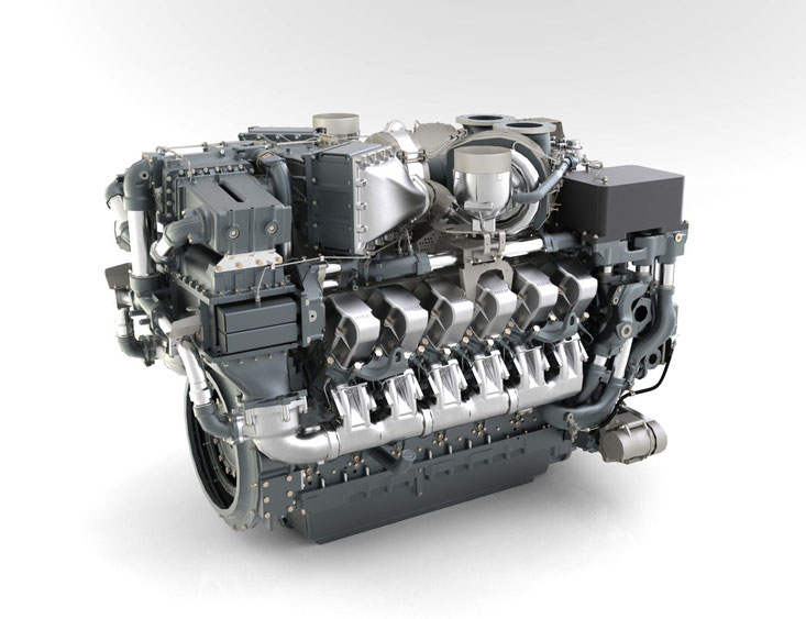
2 General Information 2.1 Engine side and cylinder designations Engine sides are always designated as viewed from the driving end (KS). The cylinders of the left engine side are designated «A» and those of the right side «B» (as per DIN ISO 1204).
-
Page 18: Engine Layout
2.2 Engine layout Illustration is also valid for 16V 4000 Sx3 engines 1 Oil heat exchanger 8 Cylinder head cover 15 Automatic oil filter (safety 2 Crankcase breather 9 Engine suspension oil filter is optional) 3 Air intake connection 10 Oil pan 16 Coolant filter 4 Exhaust turbocharger 11 Engine governor…
-
Page 19: Sensors And Actuators — Overview
2.3 Sensors and actuators – Overview Illustration also applies to 16V 4000 Sx3 engines a Version with easy-change 3 B05 (lube oil pressure) 7 B34 (fuel pressure after fil- filter 4 B44 (turbocharger speed) ter) b Version with automatic fil- 5 Injectors Y39.1 to Y39.6 8 F46 Leak fuel level moni- (A-bank)
-
Page 20
1 B50 (crankcase pressure) 4 B48 (fuel pressure in com- 7 B26 (charge-air coolant 2 B05 (lube oil pressure) mon rail) temperature) 3 B33 (fuel temperature in 5 B01 (camshaft speed) 8 B06 (coolant temperature) common rail) 6 B43 (charge-air coolant pressure) 20 | General Information | MS150027/02E 2013-02… -
Page 21
1 Injectors Y39.11 to 3 B10 (charge-air pressure) 5 B09 (charge-air tempera- Y39.16 (B-bank) 4 XM2 Oil priming pump ture) 2 B16 (coolant pressure) The injectors are located below the cylinder head covers. Injector replacement and required procedure (→ Page 76) MS150027/02E 2013-02 | General Information | 21… -
Page 22
1 B13 (crankshaft speed) 22 | General Information | MS150027/02E 2013-02… -
Page 23: Technical Data
3 Technical Data 3.1 12/16V 4000 S83L 4D engine data Explanation: DL Ref. value: Continuous power BL Ref. value: Fuel stop power A Design value G Guaranteed value R Guideline value L Limit value, up to which the engine can be operated, without change (e.g. of power settings). N Not yet defined value — Not applicable X Applicable…
-
Page 24
CONSUMPTION Number of cylinders 16 V Lube oil consumption after 100 % of B hrs run time (B = hourly fuel con- sumption) MODEL RELATED DATA (basic design) Number of cylinders 16 V Number of cylinders Cylinder arrangement: V angle Degrees Bore Stroke… -
Page 25
COOLANT SYSTEM (LT circuit) Number of cylinders 16 V Coolant temperature (at engine °C connection: outlet to cooling equipment) Coolant temperature differential °C after/before intercooler, min. Coolant temperature differential °C after/before intercooler, max. Coolant antifreeze content, max. Charge-air temperature after in- °C tercooler, max. -
Page 26
INCLINATIONS, STANDARD OIL SYSTEM (Reference: waterline) Number of cylinders 16 V Longitudinal inclination, continu- Degrees ous max., driving end down (Op- tion: max. operating inclinations) Longitudinal inclination, continu- Degrees ous max., driving end up (Option: max. operating inclinations) Transverse inclination, constant Degrees max. -
Page 27: Firing Order
3.2 Firing order Firing order Num- Firing order ber of cylin- ders A1-B4-A4-A2-B3-A3-B2-B1 A1-B5-A5-B3-A3-B6-A6-B2-A2-B4-A4-B1 16 V A1-A7-B4-B6-A4-B8-A2-A8-B3-B5-A3-A5-B2-A6-B1-B7 20 V A1-B5-A8-B7-A5-B2-A7-B10-A2-B3-A10-B6-A3-B4-A6-B9-A4-B1-A9-B8 MS150027/02E 2013-02 | Technical Data | 27…
-
Page 28: Engine — Main Dimensions
3.3 Engine – Main dimensions Engine – Main dimensions Length (A) 12V approx. 2490 mm Length (A) 16V approx. 2960 mm Width (B) 12V, 16V approx. 1449 mm Height (C) 12V, 16V approx. 1871 mm 28 | Technical Data | MS150027/02E 2013-02…
-
Page 29: Operation
4 Operation 4.1 Preparations for recommissioning the engine after extended out-of-service periods (>3 months) Preconditions ☑Engine shut down and secured against being restarted. ☑MTU Corrosion-proofing and Reproofing Regulations (A001070/..) are available. Recommissioning after long out-of-service periods (>3 months) Item Action Engine Remove corrosion-proofing (→…
-
Page 30: Putting The Engine Into Operation After Scheduled Out-Of-Service Period
4.2 Putting the engine into operation after scheduled out-of- service period Preconditions ☑Engine is stopped and starting disabled. Putting into operation Item Task Lube oil system Check engine oil level (→ Page 90). Coolant system Check engine coolant level (→ Page 101); Check charge-air coolant level (→…
-
Page 31: Starting The Engine In Manual Mode
4.3 Starting the engine in manual mode Preconditions ☑Engine is not under load. DANGER Unguarded rotating and moving engine components. Risk of serious injury – danger to life! • Before barring or starting the engine, make sure that nobody is in the danger zone. WARNING Engine noise above 85 dB (A).
-
Page 32: Operational Checks
4.4 Operational checks DANGER Unguarded rotating and moving engine components. Risk of serious injury – danger to life! • Take special care when working on a running engine. WARNING Engine noise above 85 dB (A). Risk of damage to hearing! •…
-
Page 33: Stopping The Engine In Manual Mode
4.5 Stopping the engine in manual mode Preconditions ☑Engine is not under load. ☑Engine is running in manual mode. CAUTION Stopping the engine when it is running at full load causes extreme stress to the engine. Risk of overheating, damage to components! •…
-
Page 34: After Shutting Down The Engine
4.6 After shutting down the engine Preconditions ☑MTU Corrosion-proofing and Reproofing Regulations (A001070/..) are available. After shutting down the engine Item Action Coolant system Drain coolant (→ Page 103), (→ Page 112), if: • freezing temperatures are expected and the engine is to remain out of service for an extended period, but engine coolant has no antifreeze addi- tive;…
-
Page 35: Plant Cleaning
4.7 Plant cleaning Preconditions ☑Engine is stopped and starting disabled. ☑Operating voltage is not present. Special tools, Material, Spare parts Designation / Use Part No. Qty. Steam jet cleaner Cleaner (Hakupur 312) 30390 WARNING Compressed air Risk of injury! • Do not direct compressed-air jet at persons. •…
-
Page 36: Maintenance
5 Maintenance 5.1 Maintenance task reference table [QL1] The maintenance tasks and intervals for this product are defined in the Maintenance Schedule. The Maintenance Schedule is a stand-alone publication. The task numbers in this table provide reference to the maintenance tasks specified in the Maintenance Schedule.
-
Page 37: Troubleshooting
6 Troubleshooting 6.1 Troubleshooting Engine does not turn when starter is actuated Component Probable Cause Task Battery Low or defective Charge or replace (see manufacturer’s documentation). Cable connections defective Check whether cable connections are properly secured (see manufacturer’s documentation). Starter (electric) Engine wiring or starter defective Check whether cable connections are Starter (pneumatic)
-
Page 38
Defective Contact Service. Charge-air temperature too high Component Probable Cause Task Engine coolant Incorrect coolant concentration Check (MTU test kit). Charge-air cooler Contaminated Contact Service. Engine room Air-intake temperature too high Check fans and air supply / ventilation ducts. Charge-air pressure too low… -
Page 39
Exhaust gas blue Component Probable Cause Task Engine oil Too much oil in engine Drain engine oil (→ Page 91). Oil separator of crankcase breather con- Replace (→ Page 67). taminated Exhaust turbocharger, Defective Contact Service. cylinder head, piston rings, cylinder liner Exhaust gas white Component Probable Cause… -
Page 40: Fault Messages From The Adec (Ecu 7) Engine Management Control Unit For The Series 4000 For C&I Applications
6.2 Fault messages from the ADEC (ECU 7) engine management control unit for the Series 4000 for C&I applications The fault code numbers are generated by the Engine Control Unit and transmitted to the following dis- play unit. The fault code (1) is made up of two letters and three numbers. The letters (e.g. «SE») indicate some- thing about the device or the functional area that the message originates from.
-
Page 41
No. of as- sociated Fault code no. Description Meaning Action parameter Preliminary warning: fuel 2.0122.93 HI T-Fuel temperature too high. Notify Service. Main warning: fuel tempera- ture too high; engine shut- 2.0122.93 SS T-Fuel down. Notify Service. 1. Reduce power. Preliminary warning: charge- 2. -
Page 42
No. of as- sociated Fault code no. Description Meaning Action parameter 1. Check fuel sys- tem. 2.0151.93 HI Level Fuel Overflow Fuel overflow (1st limit). 2. Contact Service. HI TC2 Idle Speed too Turbocharger 2 idling speed 1.8004.20 High too high Notify Service. -
Page 43
No. of as- sociated Fault code no. Description Meaning Action parameter Engine must not be Main warning: crankcase restarted (risk of pressure too high; engine engine damage); 2.0106.93 SS P Crankcase shutdown. notify Service. Check fuel lines for leaks. Clean fuel prefilter. Flush fuel prefilter. -
Page 44
No. of as- sociated Fault code no. Description Meaning Action parameter Engine speed remained be- low 200 rpm. Engine shut- Check for addition- 2.2500.03 AL Engine Stall down activated. al messages. SS Idle Speed Not Alarm configuration limit; 2.1090.92 Reached idling speed not attained. -
Page 45
No. of as- sociated Fault code no. Description Meaning Action parameter Internal power sup- ply (-15 V DC) fault; automat- Replace Engine 15V POS ECU FAULT ic engine shutdown. Control Unit. Internal power sup- ply (-15 V DC) fault; automat- 15V NEG ECU FAULT ic engine shutdown. -
Page 46
No. of as- sociated Fault code no. Description Meaning Action parameter Alarm configuration; connec- tion to a node on CAN bus 2 2.0500.68 AL CAN2 Node Lost failed. Notify Service. Alarm configuration; Incor- AL CAN Incorrect Con- rect parameter values en- 2.0500.68 figuration tered in data record. -
Page 47
No. of as- sociated Fault code no. Description Meaning Action parameter AL EMU Parameter Not Alarm configuration; EMU pa- 2.0500.69 Supported rameters not supported. Notify Service. 1. Check wiring. Sensor B06 defective (cool- 2. Replace if neces- 1.8004.57 SD T Coolant ant temperature). -
Page 48
No. of as- sociated Fault code no. Description Meaning Action parameter 2. Check error mes- sage; 3. Check wiring 4. Contact Service. 5. Check sensor. 1. Check sensor and wiring. 2. Replace if neces- sary. Sensor F25 defective (differ- Fault is cleared ential pressure sensor for en- when engine re- 1.8004.58… -
Page 49
No. of as- sociated Fault code no. Description Meaning Action parameter Check sensor and SD alarm configuration; wiring, replace as Backup engine oil pressure necessary. Fault is sensor defective; short cir- cleared when en- 1.8004.62 SD Oil Pressure Backup cuit or wire break gine restarted. -
Page 50
No. of as- sociated Fault code no. Description Meaning Action parameter 1.8004.51 1.8004.51 1.8004.51 1.8004.51 1.8004.51 1.8004.51 1.8004.51 1.8004.51 Wiring, bank 1 (solenoid 1. Check solenoid WIRING CYLINDER(A1- valve 1) … wiring, bank 1 valve. 1.8004.52 A10) (solenoid valve 10) 2. -
Page 51
No. of as- sociated Fault code no. Description Meaning Action parameter 1.8004.53 1.8004.53 1.8004.53 1.8004.53 1.8004.53 1.8004.53 Open load, bank 1 (solenoid 1. Check solenoid OPEN_LOAD CYL.(A1- valve 1) … open load, valve. 1.8004.54 A10) bank 1 (solenoid valve 10) 2. -
Page 52
No. of as- sociated Fault code no. Description Meaning Action parameter 1.8004.55 1.8004.55 1.8004.55 1.8004.55 Alarm configuration; internal electronic fault (electronics possibly defective: start ITS). 1. Check solenoid If ITS returns «Electronics valve wiring. AL Injector Output OK», check other fault mes- 2. -
Page 53
No. of as- sociated Fault code no. Description Meaning Action parameter Alarm configuration; Short circuit or wire break on tran- 1.8004.63 AL Wiring TO 4 sistor output 4 (TO 4). Alarm configuration; Short circuit or wire break on tran- sistor output 1, plant side Check cabling to 2.8006.63 AL Wiring TOP 1… -
Page 54
No. of as- sociated Fault code no. Description Meaning Action parameter Alarm configuration; wire 1. Check wiring. break at digital input 2; wir- 2. Contact Service.; AL Open Load Digital In- ing defective or no resist- Check input of tar- 2.8006.62 put 2 ance across switch. -
Page 55
No. of as- sociated Fault code no. Description Meaning Action parameter Alarm configuration limit 1; HI Water Level Fuel Pre- warning: water level in fuel 2.0156.93 filter prefilter too high. Drain water. Alarm configuration limit 1; preliminary warning: coolant pressure in intercooler too Top up coolant 2.0107.92 LO P Intercooler Coolant… -
Page 56
No. of as- sociated Fault code no. Description Meaning Action parameter Alarm configuration limit 2; main warning: charge-air 2.0103.93 SS P-Charge Air pressure too high. Notify Service. Check signal trans- mitter and wiring, replace as necessa- SD alarm configuration; input signal for initial/final torque Fault is cleared SD Percent Charge Sig-… -
Page 57
No. of as- sociated Fault code no. Description Meaning Action parameter Check temperature sensor and wiring, SD alarm configuration; ana- replace as necessa- log input for Aux 2 tempera- ry. Fault is cleared ture defective; short circuit when engine re- 1.8004.58 SD T-AUX 2 or wire break… -
Page 58
No. of as- sociated Fault code no. Description Meaning Action parameter AL Comb. Alarm Red Alarm configuration; RED Check other fault 2.8006.00 (Plant) combined alert from plant. messages. Alarm configuration limit; in- Determine cause of put signal above/below limit, limit violation and 2.0291.92 AL Lim Ext. -
Page 59: Task Description
7 Task Description 7.1 Engine 7.1.1 Cranking engine manually Preconditions ☑Engine shut down and secured against being restarted. Special tools, Material, Spare parts Designation / Use Part No. Qty. Cranking tool F6555766 Cranking tool F6783293 Adapter F6558528 Ratchet with extension F30006212 DANGER Unguarded rotating and moving engine components.
-
Page 60
Cranking engine manually (tool mounted underneath) Remove grounding device or guard plate. Engage cranking tool (2) in ring gear (1) and mount on flywheel housing. • For 12/16V engines, use cranking tool F6555766 with adapter F6558528. • For 20V engines, use cranking tool F6783293. -
Page 61: Engine — Barring With Starting System
7.1.2 Engine – Barring with starting system DANGER Unguarded rotating and moving engine components. Risk of serious injury – danger to life! • Before barring or starting the engine, ensure that nobody is in the danger zone. • After working on the engine, check that all protective devices have been reinstalled and all tools removed from the engine.
-
Page 62: Engine — Test Run
7.1.3 Engine – Test run DANGER Unguarded rotating and moving engine components. Risk of serious injury – danger to life! • Before barring or starting the engine, make sure that nobody is in the danger zone. WARNING Engine noise above 85 dB (A). Risk of damage to hearing! •…
-
Page 63: Cylinder Liner
7.2 Cylinder Liner 7.2.1 Cylinder liner – Endoscopic examination Preconditions ☑Engine is stopped and starting disabled Special tools, Material, Spare parts Designation / Use Part No. Qty. Barring device F6555766 Ratchet with extension F30006212 Endoscope Y20097353 Preparatory steps Remove cylinder head cover (→ Page 74). Remove injector (→…
-
Page 64
Compile endoscopy report using the table. Use technical terms for description of the liner surface (→ Page 65). Depending on findings: • Do not take any action or • carry out a further endoscopic examination as part of maintenance work or •… -
Page 65: Instructions And Comments On Endoscopic And Visual Examination Of Cylinder Liners
7.2.2 Instructions and comments on endoscopic and visual examination of cylinder liners Terms used for endoscopic examination Use the terms listed below to describe the condition of the cylinder-liner surface in the endoscopic ex- amination report. Findings Action Minor dirt scores Minor dirt scores can occur during the assembly of a new engine (honing products, particles, broken-off burrs).
-
Page 66
Evaluation of findings and further measures The findings in the start phase of oxidation discoloration and heat discoloration are similar. A thorough investigation and compliance with the above evaluation criteria allow an unambiguous evaluation. To avoid unnecessary disassembly work, it is recommended that another inspection be carried out after further operation of the engine. -
Page 67: Crankcase Breather
7.3 Crankcase Breather 7.3.1 Crankcase breather – Oil separator replacement, diaphragm check and replacement Preconditions ☑Engine is stopped and starting disabled. Special tools, Material, Spare parts Designation / Use Part No. Qty. Torque wrench, 6-50 Nm F30027336 Ratchet F30027340 Engine oil Filter element (→…
-
Page 68
Checking diaphragm Remove cover (4). Remove spring (5), seal (2) and diaphragm (3). Check diaphragm (3) for damage, fit new diaphragm if used one is damaged. Install diaphragm (3) on housing (1). Install new seal (2) and spring (5) together with cover (4). -
Page 69: Valve Drive
7.4 Valve Drive 7.4.1 Valve gear – Lubrication Preconditions ☑Engine is stopped and starting disabled. Special tools, Material, Spare parts Designation / Use Part No. Qty. Engine oil Valve gear – Lubrication Remove cylinder head covers (→ Page 74). Fill oil chambers of valve bridges with oil. Fill oil chambers of rocker arms and adjust- ing screws with oil.
-
Page 70: Valve Clearance — Check And Adjustment
7.4.2 Valve clearance – Check and adjustment Preconditions ☑Engine shut down and starting disabled. ☑Engine coolant temperature is max. 40 °C. ☑Valves are closed. Special tools, Material, Spare parts Designation / Use Part No. Qty. Feeler gauge Y20098771 Torque wrench, 60-320 Nm F30452768 Box wrench socket, 24 mm F30039526…
-
Page 71
Rotate crankshaft with barring device in di- rection of engine rotation until the «OT-A1» marking and pointer are aligned. Diagram for 8V engines (two crankshaft positions) Diagram for 12V engines (two crankshaft positions) MS150027/02E 2013-02 | Task Description | 71… -
Page 72
Diagram for 16V engines (two crankshaft positions) Diagram for 20V engines (two crankshaft positions) Checking valve clearance at two crankshaft positions Check TDC position of piston in cylinder A1: • If the rocker arms are unloaded on cylinder A1, the piston is in firing TDC. •… -
Page 73: Adjusting Valve Clearance
Adjusting valve clearance Release locknut (1). Insert feeler gauge (3) between valve bridge and rocker arm. Use Allen key to set adjusting screw (2) so that the specified valve clearance is estab- lished. Feeler gauge (3) must just pass through gap.
-
Page 74: Cylinder Head Cover — Removal And Installation
7.4.3 Cylinder head cover – Removal and installation Preconditions ☑Engine is stopped and starting disabled. Special tools, Material, Spare parts Designation / Use Part No. Qty. Grease (Kluthe Hakuform 30-10/Emulgier) X00029933 O-ring (→ Spare Parts Catalog) Removing cylinder head cover Clean very dirty cylinder head covers (1) prior to removal.
-
Page 75: Injection Pump / Hp Pump
7.5 Injection Pump / HP Pump 7.5.1 HP pump – Filling with engine oil Preconditions ☑Engine is stopped and starting disabled. Special tools, Material, Spare parts Designation / Use Part No. Qty. Engine oil WARNING Fuels are combustible. Risk of fire and explosion! •…
-
Page 76: Injection Valve / Injector
7.6 Injection Valve / Injector 7.6.1 Injector – Replacement Special tools, Material, Spare parts Designation / Use Part No. Qty. Injector (→ Spare Parts Catalog) Replacing injector Remove injector and install new injector (→ Page 77). 76 | Task Description | MS150027/02E 2013-02…
-
Page 77: Injector — Removal And Installation
7.6.2 Injector – Removal and installation Preconditions ☑Engine is stopped and starting disabled. Special tools, Material, Spare parts Designation / Use Part No. Qty. Installation/removal tool F6789889 Milling cutter F30452739 Torque wrench, 0.5-5 Nm 0015384230 Torque wrench, 10-60 Nm F30452769 Ratchet F30027340 Torque wrench, 60-320 Nm…
-
Page 78
Remove HP fuel line (4). Remove return line (5). Note: The injector accumulator will be emptied when removing the adapter. Remove adapter (3). Remove screw (2) and take off hold-down clamp (1). Install installation/removal tool on cylinder head. Remove injector with installation/removal tool. -
Page 79
Installing injector Remove plug before installing the injec- tor. (Do not remove the plug from the HP line before installing the adapter.) Coat injector with assembly paste at the seat of the nozzle clamping nut. Fit new sealing ring (included in the scope of supply of the injector) with grease on in- jector, observe installation position of seal- ing ring. -
Page 80
Coat screw head mating face (2) and thread with engine oil. Fit hold-down clamp (1) in the correct position and use torque wrench to tighten screw (2) to the speci- fied initial tightening torque. Name Size Type Lubricant Value/Standard Screw Preload torque (Engine oil) 5 Nm to 10 Nm… -
Page 81
Mount double-walled HP line (5) and use torque wrench to tighten to the specified torque. Tightening sequence: 1 Adapter (4) 2 Rail (6) Name Size Type Lubricant Value/Standard Union nut / thrust Tightening torque 40 Nm + 5 Nm screw Fit cable connector onto injector. -
Page 82: Fuel System
7.7 Fuel System 7.7.1 Fuel system – Venting Preconditions ☑Engine is stopped and starting disabled. Special tools, Material, Spare parts Designation / Use Part No. Qty. Diesel fuel WARNING Fuels are combustible. Risk of fire and explosion! • Avoid open flames, electrical sparks and ignition sources. •…
-
Page 83: Fuel Filter
7.8 Fuel Filter 7.8.1 Fuel filter – Replacement Preconditions ☑Engine is stopped and starting disabled. Special tools, Material, Spare parts Designation / Use Part No. Qty. Filter wrench F30379104 Engine oil Easy-change filter (→ Spare Parts Catalog) WARNING Fuels are combustible. Risk of fire and explosion! •…
-
Page 84: Charge-Air Cooling
7.9 Charge-Air Cooling 7.9.1 Intercooler – Checking condensate drain for coolant discharge and obstructions DANGER Unguarded rotating and moving engine components. Risk of serious injury – danger to life! • Take special care when working on a running engine. WARNING Engine noise above 85 dB (A).
-
Page 85: Air Filter
7.10 Air Filter 7.10.1 Air filter – Replacement Special tools, Material, Spare parts Designation / Use Part No. Qty. Air filter (→ Spare Parts Catalog) Air filter – Replacement Remove air filter and install new one (→ Page 86). Reset signal ring of service indicator (→ Page 89). MS150027/02E 2013-02 | Task Description | 85…
-
Page 86: Air Filter Element — Removal And Installation
7.10.2 Air filter element – Removal and installation (optional) Preconditions ☑Engine is stopped and starting disabled. Special tools, Material, Spare parts Designation / Use Part No. Qty. Gasket (→ Spare Parts Catalog) Removing and installing air fil- ter element Release latches (9). Remove dust bowl (8) and partition (7).
-
Page 87: Starting Equipment
7.11 Starting Equipment 7.11.1 Starter – Condition check Preconditions ☑Engine is stopped and starting disabled. Checking starter condition Check securing screws of starter for secure seating and tighten if required. Check wiring (→ Page 124). MS150027/02E 2013-02 | Task Description | 87…
-
Page 88: Air Intake
7.12 Air Intake 7.12.1 Emergency air-shutoff flaps – Electric control check DANGER Unguarded rotating and moving engine components. Risk of serious injury – danger to life! • Before barring or starting the engine, make sure that nobody is in the danger zone. WARNING Air flaps close abruptly.
-
Page 89: Service Indicator — Signal Ring Position Check
7.12.2 Service indicator – Signal ring position check (optional) Preconditions ☑Engine is stopped and starting disabled. Checking signal ring position If the signal ring is completely visible in the control window (2), replace air filter (→ Page 85). After installation of new filter, press reset button (1).
-
Page 90: Lube Oil System, Lube Oil Circuit
7.13 Lube Oil System, Lube Oil Circuit 7.13.1 Checking engine oil level Checking oil level before start- ing engine Withdraw oil dipstick from guide tube and wipe it clean. Insert dipstick into guide tube and push fully home, withdraw after approx. 10 sec- onds.
-
Page 91: Engine Oil — Change
7.13.2 Engine oil – Change Preconditions ☑Engine shut down and starting disabled. ☑Engine is at operating temperature. ☑MTU Fluids and Lubricants Specifications (A001061/..) are available. Special tools, Material, Spare parts Designation / Use Part No. Qty. Torque wrench, 40-200Nm F30027337…
-
Page 92
Tighten drain screws (2) and (3) with torque wrench to the specified torque. Name Size Type Lubricant Value/Standard Screw M26 x 1.5 Tightening torque (Engine oil) 100Nm +10Nm Filling with new engine oil Open cover on filler neck. Pour oil in at filler neck up to «max.» mark at oil dipstick. -
Page 93: Engine Oil — Sample Extraction And Analysis
7.13.3 Engine oil – Sample extraction and analysis Preconditions ☑MTU Fluids and Lubricants Specifications (A001061/..) are available. Special tools, Material, Spare parts Designation / Use Part No. Qty. MTU test kit 5605892099/00 DANGER Unguarded rotating and moving engine components. Risk of serious injury – danger to life! •…
-
Page 94: Oil Filtration / Cooling
7.14 Oil Filtration / Cooling 7.14.1 Automatic oil filter – Oil filter candles replacement Preconditions ☑Engine is stopped and starting disabled. Special tools, Material, Spare parts Designation / Use Part No. Qty. Grease (Kluthe Hakuform 30-10/Emulgier) X00029933 Engine oil O-ring (→…
-
Page 95
Withdraw oil filter element (1). Remove O-ring. Remove screw (2). Withdraw plastic spinner (1) with spring. Remove nut (3). Take off spring washer and washer. Remove screw (4). Remove flushing arm (5) from screen plate (6). Turn filter element by 180° and use appro- priate tool to push out filter candles (1). -
Page 96
Installing oil filter candles For installation follow reverse sequence of working steps. Additionally, the following instructions are to be observed: • Replace all sealing elements. • Coat O-rings with grease. • Insert O-rings in grooves. • Observe position of cylinder screw to elongated hole on shaft. 96 | Task Description | MS150027/02E 2013-02… -
Page 97
7.14.2 Oil indicator filter – Cleaning and check Preconditions ☑Engine shut down and starting disabled. Special tools, Material, Spare parts Designation / Use Part No. Qty. Cleaning agent (Snow-White 11-0) 40460 Cleaning agent (Hakupur 312) 30390 Engine oil Strainer (→ Spare Parts Catalog) Square-section ring (→… -
Page 98
Checking strainer Item Findings Measure Strainer Metallic residue • Clean • Monitor engine operation • Check strainer daily • Contact Service. Strainer Damaged Fit new part Square-section ring Damaged Fit new part O-ring Damaged Fit new part Cleaning strainer Wash strainer (5) with cleaning agent. Remove stubborn deposits with soft brush. -
Page 99
7.14.3 Centrifugal oil filter – Cleaning and filter-sleeve replacement Preconditions ☑Engine is stopped and starting disabled. Special tools, Material, Spare parts Designation / Use Part No. Qty. Torque wrench, 6-50 Nm F30027336 Cold cleaner (Hakutex 60) X00056750 Filter sleeve (→ Spare Parts Catalog) Sealing ring (→… -
Page 100
Centrifugal oil filter – Cleaning and filter-sleeve replacement Remove clamp (14). Release cover screw (2) and take off cov- er (1). Carefully lift rotor (11), allow oil to drain and remove from housing. Holding the rotor (11) firmly, release rotor cover nut (3). -
Page 101
7.15 Coolant Circuit, General, High-Temperature Circuit 7.15.1 Engine coolant – Level check Preconditions ☑Engine is stopped and starting disabled. ☑MTU Fluids and Lubricants Specifications (A001061/..) are available. WARNING Coolant is hot and under pressure. Risk of injury and scalding! • Let the engine cool down. -
Page 102
7.15.2 Engine coolant – Change Special tools, Material, Spare parts Designation / Use Part No. Qty. Coolant Engine coolant – Change Drain engine coolant (→ Page 103). Fill with engine coolant (→ Page 105). 102 | Task Description | MS150027/02E 2013-02… -
Page 103
7.15.3 Draining engine coolant Preconditions ☑Engine shut down and secured against being restarted. WARNING Coolant is hot and under pressure. Risk of injury and scalding! • Let the engine cool down. • Wear protective clothing, gloves, and goggles / safety mask. Preparatory steps Have a suitable container ready to catch the coolant. -
Page 104
Open the drainage point on the main PTO end of the crankcase, on the left or right side (arrowed) and drain off the engine coolant. Close off all open drain points. Place pressure cap on filler neck and close. Concluding operations Switch on preheater. -
Page 105
7.15.4 Engine coolant – Filling Preconditions ☑Engine is stopped and starting disabled. ☑MTU Fluids and Lubricants Specifications (A001061/..) are available. Special tools, Material, Spare parts Designation / Use Part No. Qty. Engine coolant WARNING Coolant is hot and under pressure. -
Page 106
Filling with coolant using pump Connect a suitable pump with a hose to drain valve. Open drain valve and pump coolant into en- gine at 0.5 bar minimum. Fill expansion tank until overflow edge is reached. Close drain valve. Check proper condition of breather valve and clean sealing faces if required. -
Page 107
7.15.5 Engine coolant pump – Checking pressure relief port DANGER Unguarded rotating and moving engine components. Risk of serious injury – danger to life! • Take special care when working on a running engine. WARNING Engine noise above 85 dB (A). Risk of damage to hearing! •… -
Page 108
7.15.6 Engine coolant – Sample extraction and analysis Preconditions ☑MTU Fluids and Lubricants Specifications (A001061/..) are available. Special tools, Material, Spare parts Designation / Use Part No. Qty. MTU test kit 5605892099/00 DANGER Unguarded rotating and moving engine components. Risk of serious injury – danger to life! •… -
Page 109
7.15.7 Engine coolant filter – Replacement Preconditions ☑Engine is stopped and starting disabled. Special tools, Material, Spare parts Designation / Use Part No. Qty. Filter wrench F30379104 Engine oil Coolant filter (→ Spare Parts Catalog) WARNING Coolant is hot and under pressure. Risk of injury and scalding! •… -
Page 110
7.16 Low-Temperature Circuit 7.16.1 Charge-air coolant – Level check Preconditions ☑Engine is stopped and starting disabled. ☑MTU Fluids and Lubricants Specifications (A001061/..) are available. WARNING Coolant is hot and under pressure. Risk of injury and scalding! • Let the engine cool down. -
Page 111
7.16.2 Charge-air coolant – Change Special tools, Material, Spare parts Designation / Use Part No. Qty. Coolant Charge-air coolant – Change Drain charge-air coolant (→ Page 112). Fill with charge-air coolant (→ Page 113). MS150027/02E 2013-02 | Task Description | 111… -
Page 112
7.16.3 Charge-air coolant – Draining Preconditions ☑Engine is stopped and starting disabled. Special tools, Material, Spare parts Designation / Use Part No. Qty. Sealing ring (→ Spare Parts Catalog) WARNING Coolant is hot and under pressure. Risk of injury and scalding! •… -
Page 113
7.16.4 Charge-air coolant – Filling Preconditions ☑Engine is stopped and starting disabled. ☑MTU Fluids and Lubricants Specifications (A001061/..) are available. Special tools, Material, Spare parts Designation / Use Part No. Qty. Charge-air coolant WARNING Coolant is hot and under pressure. -
Page 114
Filling with charge-air coolant using pump Connect appropriate pump with hose to drain valve. Open drain valve and pump coolant into en- gine at 0.5 bar minimum. Fill expansion tank until overflow edge is reached. Close drain valve. Check proper condition of breather valve and clean sealing faces if required. -
Page 115: Charge-Air Coolant Pump – Checking Pressure
7.16.5 Charge-air coolant pump – Checking pressure relief port DANGER Unguarded rotating and moving engine components. Risk of serious injury – danger to life! • Take special care when working on a running engine. WARNING Engine noise above 85 dB (A). Risk of damage to hearing! •…
-
Page 116: Belt Drive
7.17 Belt Drive 7.17.1 Drive belt – Condition check Preconditions ☑Engine is stopped and starting disabled. ☑Guard is removed. Drive belt – Condition check Item Findings Action Drive belt A Singular cracks None Drive belt Belt is oily, shows signs of over- Replace (→…
-
Page 117: Battery-Charging Generator
7.18 Battery-Charging Generator 7.18.1 Battery-charging generator – Check Preconditions ☑Engine shut down and starting disabled. WARNING Compressed air Risk of injury! • Do not direct compressed-air jet at persons. • Wear protective goggles / safety mask and ear protectors. Checking battery-charging generator Item Findings Measure…
-
Page 118
7.18.2 Battery-charging generator drive – Drive belt tension adjustment Preconditions ☑Engine is stopped and starting disabled. Special tools, Material, Spare parts Designation / Use Part No. Qty. Torque wrench, 60-320 Nm F30452768 Ratchet F30027341 Torque wrench, 10-60 Nm F30452769 Ratchet F30027340 WARNING Spring/circlip/tensioning roller preload. -
Page 119
7.18.3 Battery-charging generator drive – Drive belt replacement Preconditions ☑Engine is stopped and starting disabled. Special tools, Material, Spare parts Designation / Use Part No. Qty. Torque wrench, 60-320 Nm F30452768 Ratchet F30027341 Torque wrench, 10-60 Nm F30452769 Ratchet F30027340 Drive belt (→… -
Page 120: Fan Drive
Hold measuring tip of belt tension tester over belt drive. Tap drive belt (arrow) with a suitable tool. Hold belt tension tester over belt drive until the measured value is indicated. Initial assembly at MTU Initial operation with fan Re-tensioning None 60 Hz ±1 Hz 52 Hz ±1 Hz…
-
Page 121
Hold measuring tip of belt tension tester over belt drive. Tap drive belt (arrow) with a suitable tool. Hold belt tension tester over belt drive until the measured value is indicated. Initial assembly at MTU Initial operation with fan Re-tensioning 36 Hz ±5 Hz 49 Hz ±2 Hz… -
Page 122
7.19.2 Fan drive – Drive belt replacement Preconditions ☑Engine is stopped and starting disabled. Special tools, Material, Spare parts Designation / Use Part No. Qty. Drive belt (→ Spare Parts Catalog) Preparatory steps Remove protective cover. Remove fan. Replacing drive belt Release screws (2). -
Page 123
7.20 Engine Mounting / Support 7.20.1 Engine mounting – Check Engine mounting – Check Item Findings Action Visually inspect mounts. • Damage Replace (contact Service). • Brittleness • Deformation • Crack formation • Swelling visible MS150027/02E 2013-02 | Task Description | 123… -
Page 124
7.21 Wiring (General) for Engine/Gearbox/Unit 7.21.1 Engine wiring – Check Preconditions ☑Engine is stopped and starting disabled. Special tools, Material, Spare parts Designation / Use Part No. Qty. Isopropyl alcohol X00058037 Engine wiring – Check Check securing screws of cable clamps on engine and tighten loose threaded connections. Ensure that cables are fixed in their clamps and cannot swing freely. -
Page 125
7.22 Accessories for (Electronic) Engine Governor / Control System 7.22.1 Engine governor and connectors – Cleaning Preconditions ☑Engine is stopped and starting disabled. Special tools, Material, Spare parts Designation / Use Part No. Qty. Isopropyl alcohol X00058037 Note: Always use test connectors to enter the connectors. Never use test leads for this purpose.Otherwise the contacts could be bent. -
Page 126
7.22.2 Engine governor plug connections – Check Preconditions ☑Engine is stopped and starting disabled. Note: Always use test plugs to check the connections. Never use test leads. Otherwise, the contacts might be bent. Engine governor plug connections – Check Check all plug connections for secure seating. Latch plugs if loose. -
Page 127
Abgasturbolader Exhust turbocharger (ETC) Air Temperature Sensor Baureihe Series Betriebsstoffvorschrift MTU Fluids and Lubricants Specifications, publica- tion No. A01061/.. Controller Area Network Data bus system, bus standard Calibration Drift Compensation Setting of drift compensation in engine governor with DiaSys… -
Page 128
Abbre- Meaning Explanation viation Ersatzteilkatalog Spare Parts Catalog (SPC) Electronic Unit Injector Fuel Pressure Sensor Fuel Differential Pressure Sensor Fuel Temperature Sensor FWCP Fire Water Control Panel Ground High pressure High Alarm: Measured value exceeds 1st maximum limit HIHI High High Alarm: Measured value exceeds 2nd maximum limit value High Temperature… -
Page 129
Abbre- Meaning Explanation viation Synchronous Reference Sensor TDC cylinder 1 Safety System Safety system alarm Turbocharger Boost Sensor Monitors charge-air pressure Turbo Compressor Inlet Turbo Compressor Outlet Transmitter Deviation Alarm: Deviation in transmitter values Throttle Position Sensor Timing Reference Sensor T-xyz Temperature-xyz Temperature measuring point, xyz specifies the… -
Page 130
Local support Experienced and qualified specialists place their knowledge and expertise at your disposal. For locally available support, go to the MTU Internet site: http://www.mtu-online.com 24h hotline With our 24h hotline and the outstanding flexibility of our service staff, we are always ready to assist you –… -
Page 131: Special Tools
9 Appendix B 9.1 Special Tools Adapter Part No.: F6558528 Qty.: Used in: 7.1.1 Cranking engine manually (→ Page 59) Barring device Part No.: F6555766 Qty.: Used in: 7.2.1 Cylinder liner – Endoscopic examination (→ Page 63) Box wrench socket, 24 mm Part No.: F30039526 Qty.:…
-
Page 132
Cranking tool Part No.: F6555766 Qty.: Used in: 7.1.1 Cranking engine manually (→ Page 59) Cranking tool Part No.: F6783293 Qty.: Used in: 7.1.1 Cranking engine manually (→ Page 59) Endoscope Part No.: Y20097353 Qty.: Used in: 7.2.1 Cylinder liner – Endoscopic examination (→… -
Page 133
7.6.2 Injector – Removal and installation (→ Page 77) Milling cutter Part No.: F30452739 Qty.: Used in: 7.6.2 Injector – Removal and installation (→ Page 77) MTU test kit Part No.: 5605892099/00 Qty.: Used in: 7.13.3 Engine oil – Sample extraction and analysis (→ Page 93) Qty.:… -
Page 134
Optibell 2 belt tension tester Part No.: Y4345711 Qty.: Used in: 7.19.1 Fan drive – Drive belt tension check / adjust- ment (→ Page 120) Ratchet Part No.: F30027340 Qty.: Used in: 7.3.1 Crankcase breather – Oil separator replacement, diaphragm check and replacement (→ Page 67) Qty.: Used in: 7.6.2 Injector –… -
Page 135
Ratchet with extension Part No.: F30006212 Qty.: Used in: 7.1.1 Cranking engine manually (→ Page 59) Qty.: Used in: 7.2.1 Cylinder liner – Endoscopic examination (→ Page 63) Steam jet cleaner Part No.: Qty.: Used in: 4.7 Plant cleaning (→ Page 35) Torque wrench, 0.5-5 Nm Part No.: 0015384230… -
Page 136
Torque wrench, 40-200Nm Part No.: F30027337 Qty.: Used in: 7.13.2 Engine oil – Change (→ Page 91) Torque wrench, 6-50 Nm Part No.: F30027336 Qty.: Used in: 7.3.1 Crankcase breather – Oil separator replacement, diaphragm check and replacement (→ Page 67) Torque wrench, 6-50 Nm Part No.: F30027336… -
Page 137
9.2 Index Numerics 12/16V 4000 S83L 4D engine data 23 Emergency air-shutoff flaps – Electric control check 88 Engine Abbreviations 127 – Barring with starting system 61 After shutting down the engine 34 – Cranking manually 59 Air filter – Layout 18 – Replacement 85 –… -
Page 138
– Lubrication 69 – Checking condensate drain for coolant discharge 84 – Checking condensate drain for obstructions 84 Wiring — engine – Check 124 MTU contact persons 130 Oil indicator filter – Check 97 – Cleaning 97 Oil separator element – Replacement 67…
-
Contents
-
Table of Contents
-
Troubleshooting
-
Bookmarks
Quick Links
Operating Instructions
Diesel engine
12 V 4000 C10, C10R, C11, C11R
12 V 4000 C20, C20R, C21, C21R
16 V 4000 C10, C11, C11R
16 V 4000 C20, C20R, C21, C21L
MS150049/02E
Related Manuals for MTU 12 V 4000 C10
Summary of Contents for MTU 12 V 4000 C10
-
Page 1: Operating Instructions
Operating Instructions Diesel engine 12 V 4000 C10, C10R, C11, C11R 12 V 4000 C20, C20R, C21, C21R 16 V 4000 C10, C11, C11R 16 V 4000 C20, C20R, C21, C21L MS150049/02E…
-
Page 2
This Publication is protected by copyright and may not be used in any way whether in whole or in part without the prior written permission of MTU Friedrichshafen GmbH. This restriction also applies to copyright, distribution, translation, micro‐ filming and storage or processing on electronic systems including data bases and online services. -
Page 3: Table Of Contents
7.3 Crankcase Breather 3 Technical Data 7.3.1 Crankcase breather – Filter element replacement 3.1 Engine data 12 V 4000 C10, C10R, C11, 7.3.2 Crankcase breather (open-circuit crankcase C11R ventilation) – Filter element cleaning 3.2 Engine data 16 V 4000 C10, C11, C11R 7.4 Running Gear…
-
Page 4
8 Appendix A 7.16 Low-Temperature Circuit 8.1 Abbreviations 7.16.1 Charge-air coolant – Level check 8.2 MTU contact persons/service partners 7.16.2 Charge-air coolant – Change 7.16.3 Charge-air coolant – Drainage 7.16.4 Charge-air coolant – Filling 7.16.5 Charge-air coolant pump – Relief bore check 9 Appendix B 7.17 Engine Mounting / Support… -
Page 5: Safety
Spare parts Only genuine MTU spare parts must be used to replace components or assemblies. MTU will accept no liability or warranty claims for any damage caused by the use of other spare parts. MS150049/02E 2012-11 | Safety | 5…
-
Page 6: Personnel And Organizational Requirements
Personnel requirements All work on the engine or plant shall be carried out by trained and qualified personnel only: • Training at the MTU Training Center • Qualified personnel specialized in mechanical and plant engineering The operator must define the responsibilities of the personnel involved in operation, maintenance, repair and transport.
-
Page 7: Transport
Place the engine/genset on a firm, flat surface only. Make sure that the consistency and load-bearing capacity of the ground or support surface is adequate. Never set an engine down on the oil pan unless expressively authorized to do so by MTU on a case-to- case basis.
-
Page 8: Crankshaft Transport Locking Device
1.4 Crankshaft transport locking device Special tools, Material, Spare parts Designation / Use Part No. Qty. Torque wrench, 10-60Nm F30452769 Torque wrench, 60-320Nm F30452768 Engine oil Note: The transport locking device on both sides protects the crankshaft bearings from shocks and possible vibration damage during engine transport.
-
Page 9
Installing the transport locking device on driving end (KS), version Screw holder (4) with spacer sleeves (5) and screws (6) onto crankshaft. Spacer sleeves (5), optional. Tighten screws (6) with torque wrench to specified tightening torque. Name Size Type Lubricant Value/Standard Screw Tightening torque… -
Page 10
Installing the transport locking device on driving end (KS), version Secure plate (1) with screws (5) and washers (4) together with cover plate (7) at the bores on both sides of the flywheel housing and tighten to the specified tightening torque. Name Size Type… -
Page 11: Crankshaft Transport Locking Device — For Transport With Flanged-On Generator
Screw Tightening torque (Engine oil) 250Nm +25Nm Installing the transport locking device on driving end (KS) Remove the transport locking device installed by MTU (→ Page 8). Remove protective cover from flywheel housing (1). MS150049/02E 2012-11 | Safety | 11…
-
Page 12
Install the holders (7) on both sides of the crankcase (12) with screw (9) and washer (8). Tighten screw (9). Name Size Type Lubricant Value/Standard Screw Tightening torque (Engine oil) 290Nm +20Nm To allow the holders (3) to be secured on each side of the flywheel (2), the corresponding screws and washers must be removed from the driving end. -
Page 13: Safety Regulations For Startup And Operation
Before the engine or plant is put into operation for the first time, the engine or plant must be installed and accepted in accordance with MTU specifications. Before the engine or plant is put into operation for the first time, all official authorizations must be availa‐…
-
Page 14: Safety Regulations For Maintenance And Repair Work
1.7 Safety regulations for maintenance and repair work Safety regulations prior to maintenance and repair work Have maintenance and repair work carried out by qualified and authorized personnel only. Allow the engine or plant to cool down to less than 50°C before starting maintenance work (risk of explo‐ sion of oil vapors, fluids and lubricants, risk of burning).
-
Page 15
Safety regulations after completion of maintenance and repair work Before barring the engine, make sure that nobody is standing in the danger zone of the engine or plant. Check that all guards have been reinstalled and that all tools and loose parts have been removed after working on the engine or plant (in particular, the barring tool). -
Page 16
Store spare parts properly prior to replacement, i.e. protect them against moisture in particular. Pack de‐ fective electronic components and assemblies in a suitable manner when dispatched for repair, i.e. par‐ ticularly protected against moisture and impact and wrapped in antistatic foil if necessary. Working with laser equipment When working with laser equipment, always wear special laser-protection goggles ⇒… -
Page 17: Fire Prevention And Environmental Protection, Auxiliary Materials, Fluids And Lubricants
Dispose of used fluids, lubricants and filters in accordance with local regulations. Within the EU, batteries can be returned free of charge to MTU FN / MTU Onsite Energy where they are subjected to proper recycling procedures.
-
Page 18
Lead • Adopt suitable measures to avoid the formation of lead dust. • Switch on extraction system. • When working with lead or lead-containing compounds, avoid direct contact to the skin and do not inhale lead vapors. • Wash hands after contact with lead or lead-containing substances. Compressed air Observe special safety precautions when working with compressed air: •… -
Page 19: Standards For Safety Messages In The Text
1.9 Standards for safety messages in the text DANGER In the event of immediate danger. Consequences: Death or serious injury • Remedial action WARNING In the event of potentially dangerous situations. Consequences: Death or serious injury • Remedial action CAUTION In the event of hazardous situations.
-
Page 20: General Information
2 General Information 2.1 Engine side and cylinder designations Engine sides are always designated as viewed from the driving end (KS). The cylinders of the left engine side are designated «A» and those of the right side «B» (as per DIN ISO 1204).
-
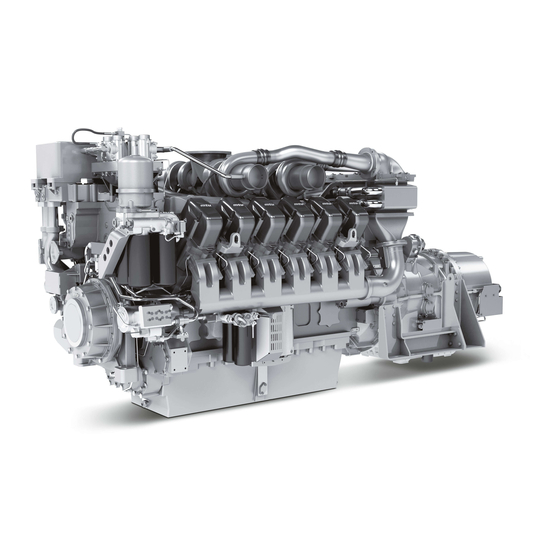
Page 21: Engine — Overview
2.2 Engine – Overview Figure applies to 16V4000 Cxy analogously 1 Oil cooler 8 Combustion-air inlet 15 Air conditioning com‐ 2 Fan coupling 9 Charge-air cooler pressor drive 3 Crankcase breather 10 Charge-air line 16 HP pump 4 Control valve for fan 11 Starter 17 Engine mounting coupling…
-
Page 22
1 Charge-air line 8 Lifting eyes 15 Crankcase 2 Cylinder head / cylinder 9 Crankcase breather 16 Flywheel housing head cover 10 Charge-air coolant inlet 17 Flywheel 3 Crankcase breather 11 Engine coolant pump 18 Charge-air line 4 Coolant circuit / vent 12 Inspection port cover 19 Charge-air cooler connection… -
Page 23: Sensors, Actuators And Injectors — Overview
2.3 Sensors, actuators and injectors – Overview 1 Engine coolant temper‐ 3 Charge-air temperature ature 4 Charge-air pressure 2 Crankshaft speed The injectors are underneath the cylinder head covers of the cylinder. Injector replacement and necessa‐ ry activities (→ Page 91). MS150049/02E 2012-11 | General Information | 23…
-
Page 24
1 Camshaft speed 3 Fuel temperature 5 Charge-air coolant pres‐ 2 Fuel pressure (LP) 4 Fuel high pressure sure 6 Engine coolant pressure 24 | General Information | MS150049/02E 2012-11… -
Page 25
1 Lube oil temperature 3 Crankcase pressure 2 Lube oil pressure 4 Charge-air coolant tem‐ perature MS150049/02E 2012-11 | General Information | 25… -
Page 26: Technical Data
3 Technical Data 3.1 Engine data 12 V 4000 C10, C10R, C11, C11R Explanation Abbr. Meaning Reference value: Continuous power Reference value: Fuel stop power Design value Guaranteed value Guideline value Limit value, up to which the engine can be operated, without change (e.g. of power set‐…
-
Page 27
MODEL RELATED DATA (basic design) Number of cylinders Cylinder arrangement: V angle Degrees Bore Stroke Displacement of a cylinder Liters Displacement, total Liters 48.80 48.80 48.80 48.80 Number of inlet valves per cylinder Number of exhaust valves per cylinder COMBUSTION AIR / EXHAUST GAS Number of cylinders Charge-air pressure before cylinder 1.95… -
Page 28
NOISE Number of cylinders Unsilenced exhaust noise at 1m dis‐ dB(A) tance 28 | Technical Data | MS150049/02E 2012-11… -
Page 29: Engine Data 16 V 4000 C10, C11, C11R
3.2 Engine data 16 V 4000 C10, C11, C11R Explanation Abbr. Meaning Reference value: Continuous power Reference value: Fuel stop power Design value Guaranteed value Guideline value Limit value, up to which the engine can be operated, without change (e.g. of power set‐ ting) Not yet defined value Not applicable…
-
Page 30
MODEL RELATED DATA (basic design) Number of cylinders Cylinder arrangement: V angle Degrees Bore Stroke Displacement of a cylinder Liters Displacement, total Liters 65.0 65.0 65.0 Number of inlet valves per cylinder Number of exhaust valves per cylinder COMBUSTION AIR / EXHAUST GAS Number of cylinders Charge-air pressure before cylinder 1.95… -
Page 31
NOISE Number of cylinders Unsilenced exhaust noise at 1m distance dB(A) MS150049/02E 2012-11 | Technical Data | 31… -
Page 32: Engine Data 12 V 4000 C20, C20R, C21, C21R
3.3 Engine data 12 V 4000 C20, C20R, C21, C21R Explanation Abbr. Meaning Reference value: Continuous power Reference value: Fuel stop power Design value Guaranteed value Guideline value Limit value, up to which the engine can be operated, without change (e.g. of power set‐ ting) Not yet defined value Not applicable…
-
Page 33
MODEL RELATED DATA (basic design) Number of cylinders Cylinder arrangement: V angle Degrees Bore Stroke Displacement of a cylinder Liters Displacement, total Liters 48.80 48.80 48.80 48.80 Number of inlet valves per cylinder Number of exhaust valves per cylinder COMBUSTION AIR / EXHAUST GAS Number of cylinders Charge-air pressure before cylinder Exhaust gas temperature… -
Page 34
NOISE Number of cylinders Unsilenced exhaust noise at 1m dis‐ dB(A) tance 34 | Technical Data | MS150049/02E 2012-11… -
Page 35: Engine Data 16 V 4000 C20, C20R, C21, C21L
3.4 Engine data 16 V 4000 C20, C20R, C21, C21L Explanation Abbr. Meaning Reference value: Continuous power Reference value: Fuel stop power Design value Guaranteed value Guideline value Limit value, up to which the engine can be operated, without change (e.g. of power set‐ ting) Not yet defined value Not applicable…
-
Page 36
MODEL RELATED DATA (basic design) Number of cylinders Cylinder arrangement: V angle Degrees Bore Stroke Displacement of a cylinder Liters Displacement, total Liters 65.0 65.0 65.0 65.0 Number of inlet valves per cylinder Number of exhaust valves per cylinder COMBUSTION AIR / EXHAUST GAS Number of cylinders Charge-air pressure before cylinder Exhaust gas temperature… -
Page 37
NOISE Number of cylinders Unsilenced exhaust noise at 1m dis‐ dB(A) tance MS150049/02E 2012-11 | Technical Data | 37… -
Page 38: Firing Order
3.5 Firing order Firing order Number of cylin‐ Firing order ders A1-B4-A4-A2-B3-A3-B2-B1 A1-B2-A5-B4-A3-B1-A6-B5-A2-B3-A4-B6 16 V A1-A7-B4-B6-A4-B8-A2-A8-B3-B5-A3-A5-B2-A6-B1-B7 20 V A1-B5-A8-B7-A5-B2-A7-B10-A2-B3-A10-B6-A3-B4-A6-B9-A4-B1-A9-B8 38 | Technical Data | MS150049/02E 2012-11…
-
Page 39: Engine — Main Dimensions
3.6 Engine – Main dimensions Engine model Length (A) Width (B) Height (C) 12 V 4000 Cxy approx. 2540 mm approx. 1620 mm approx. 1990 mm 16 V 4000 Cxy approx. 3010 mm approx. 1620 mm approx. 1990 mm MS150049/02E 2012-11 | Technical Data | 39…
-
Page 40: Operation
4.1 Putting the engine into operation after extended out-of- service periods (>3 months) Preconditions ☑ Engine is stopped and starting disabled. ☑ MTU Fluids and Lubricants Specifications (A001061/..) are available. Putting the engine into operation after extended out-of-service-periods (>3 months) Item Action Engine Depreserve (→…
-
Page 41: Putting The Engine Into Operation After Scheduled Out-Of-Service-Period
4.2 Putting the engine into operation after scheduled out-of- service-period Preconditions ☑ Engine is stopped and starting disabled. Startup Item Action Lube oil system Check engine oil level (→ Page 103). Coolant circuit Check engine coolant level (→ Page 112); Check charge-air coolant level (→…
-
Page 42: Starting The Engine In Manual Mode
4.3 Starting the engine in manual mode Preconditions ☑ Engine is not under load. ☑ External start interlock is not activated. DANGER Unguarded rotating and moving engine components. Risk of serious injury – danger to life! • Before barring or starting the engine, make sure that nobody is in the danger zone. WARNING Engine noise above 85 dB (A).
-
Page 43: Operational Checks
4.4 Operational checks DANGER Unguarded rotating and moving engine components. Risk of serious injury – danger to life! • Take special care when working on a running engine. WARNING Engine noise above 85 dB (A). Risk of damage to hearing! •…
-
Page 44: Stopping The Engine In Manual Mode
4.5 Stopping the engine in manual mode Preconditions ☑ Engine is not under load. ☑ Engine is running in manual mode. CAUTION Stopping the engine when it is running at full load causes extreme stress to the engine. Risk of overheating, damage to components! •…
-
Page 45: After Stopping The Engine
4.6 After stopping the engine Preconditions ☑ MTU Fluids and Lubricants Specifications (A001061/..) are available. After stopping the engine Item Action Coolant circuit Drain coolant (→ Page 114)(→ Page 122) if: • freezing temperatures are expected and the engine is to remain out of service for an extended period, but engine coolant has no antifreeze additive;…
-
Page 46: Plant Cleaning
4.7 Plant cleaning Preconditions ☑ Engine is stopped and starting disabled. ☑ Operating voltage is not present. Special tools, Material, Spare parts Designation / Use Part No. Qty. Steam jet cleaner Cleaner (Hakupur 312) 30390 WARNING Compressed air Risk of injury! •…
-
Page 47: Maintenance
5 Maintenance 5.1 Maintenance task reference table [QL1] The maintenance tasks and intervals for this product are defined in the Maintenance Schedule. The Maintenance Schedule is a stand-alone publication. The task numbers in this table provide reference to the maintenance tasks specified in the Maintenance Schedule.
-
Page 48
Task Option Maintenance tasks W1698 X Replace carbon brushes at flywheel. (→ Page 83) W1716 Cleaning battery-charging generator. (→ Page 131) Table 1: Maintenance task reference table [QL1] 48 | Maintenance | MS150049/02E 2012-11… -
Page 49: Troubleshooting
6 Troubleshooting 6.1 Troubleshooting Engine does not turn when starter is actuated Component Cause Action Battery Low or faulty Charge or replace (see manufacturer’s documentation). Cable connections faulty Check if cable connections are proper‐ ly secured (see manufacturer’s docu‐ mentation). Starter Engine cabling or starter faulty Check if cable connections are proper‐…
-
Page 50
Faulty Contact Service. Charge air temperature too high Component Cause Action Engine coolant Engine coolant treatment incorrect Check (MTU test kit). Intercooler Contaminated Contact Service. Engine room Air-intake temperature too high Check fans and intake/exhaust lines. Charge-air pressure too low… -
Page 51
Blue exhaust gas Component Cause Action Engine oil Too much oil in engine Drain engine oil (→ Page 104). Filter element in oil separator is clog‐ Replace (→ Page 78). Exhaust turbocharg‐ Faulty Contact Service. er, cylinder head, pis‐ ton rings, cylinder lin‐ White exhaust gas Component Cause… -
Page 52: Fault Messages From Ddec Engine Governor
6.2 Fault messages from DDEC engine governor The DDEC engine governor generates alarms which are indicated in different ways depending on the equipment configuration: • Two-digit flashing code • Fault code and text on a display or PC screen To facilitate troubleshooting without additional auxiliary equipment, the two-digit flash codes can be read out from the DDEC by means of the vehicle-side alarm lamps CHECK ENGINE LIGHT (yellow) and STOP ENGINE LIGHT (red).
-
Page 53
Additional accessories: • Printer (part no. J-38699) for direct connection to the DDR • Spare paper (part no. J-38480-5) for the printer (5 rolls respectively) The following information is available on reading out the fault codes with the DDR. Example: MID:128 Engine TURBO… -
Page 54
Flashi Description Maintenance tasks code Coolant level sensor, input 1. Check coolant condition voltage too low. (→ Page 119). 2. Check coolant level, top up if required (→ Page 112). 3. Check cabling. 4. Contact Service. Sensor «Top up coolant», in‐ 1. -
Page 55
Flashi Description Maintenance tasks code Throttle sensor, input volt‐ 1. Check cabling. age too low. 2. Contact Service. Blower bypass position, in‐ 1. Check cabling. put voltage too low. 2. Contact Service. Humidity sensor, electric 1. Check cabling. circuit defective / low (ver‐ 2. -
Page 56
Flashi Description Maintenance tasks code Temperature sensor/ ex‐ 1. Check cabling. haust turbocharger outlet, 2. Contact Service. input voltage too low (ver‐ sion 32.0 or later). Auxiliary output 3, open cir‐ Contact Service. cuit (side «high») S3. Auxiliary output 3, ground Contact Service. -
Page 57
Flashi Description Maintenance tasks code Fuel differential pressure 1. Check cabling. sensor, input voltage too 2. Contact Service. high. Fuel pressure sensor upper 1. Check cabling. level, input voltage too low. 2. Contact Service. Fuel pressure sensor, input 1. Check cabling. voltage too low. -
Page 58
Flashi Description Maintenance tasks code Coolant level too low. 1. Check coolant level, top up if required (→ Page 112). 2. Contact Service. Intercooler coolant temper‐ 1. Check coolant condition ature too high. (→ Page 119). 2. Check coolant level, top up if required (→… -
Page 59
Flashi Description Maintenance tasks code ECM battery voltage too Contact Service. low. Real-time clock auxiliary Contact Service. battery, voltage too low (version 29.0 or later). Sensor supply voltage too Contact Service. low. High range: Fuel pressure Contact Service. too high. Fuel pressure too high. -
Page 60
Flashi Description Maintenance tasks code Temperature at exhaust tur‐ 1. Check contamination indica‐ bocharger outlet too high tor signal ring position (version 32.0 or later). (→ Page 102). 2. Check exhaust system. 3. Contact Service. TCO temperature- power Contact Service. reduction. -
Page 61
Flashi Description Maintenance tasks code Auxiliary output 2, short cir‐ Contact Service. cuit on battery circuit (plus) Auxiliary output 2, open cir‐ Contact Service. cuit A2. Auxiliary output 2, mechani‐ Contact Service. cal system does not re‐ spond correctly A2. Auxiliary output 5, short cir‐… -
Page 62
Flashi Description Maintenance tasks code PWM 2 above normal Contact Service. range. PWM 2 below normal Contact Service. range. PWM 2 short circuit on bat‐ Contact Service. tery circuit (plus). PWM 2 open circuit. Contact Service. PWM 3 above normal Contact Service. -
Page 63
Flashi Description Maintenance tasks code Knock sensor, input voltage Contact Service. too high. Knock sensor, input voltage Contact Service. too low. Knock sensor does not re‐ Contact Service. spond. Coolant pressure sensor, Contact Service. high range (input voltage too high). Coolant pressure sensor, Contact Service. -
Page 64
Flashi Description Maintenance tasks code Gas valve position input Contact Service. voltage too low. Gas dosing valve does not Contact Service. respond. ESS transmission, engaged Contact Service. gear step jamming. Transmission idling switch Contact Service. defective, (ESS transmis‐ sion). Analog auxiliary input: data Contact Service. -
Page 65
Flashi Description Maintenance tasks code Exhaust back pressure too Contact Service. low. Exhaust back pressure sen‐ Contact Service. sor voltage too high. Exhaust back pressure sen‐ Contact Service. sor voltage too low. Exhaust back pressure near Contact Service. limit for power reduction. Fuel filter differential pres‐… -
Page 66
Flashi Description Maintenance tasks code Clock module with irregular Contact Service. alteration speed. Clock module faulty. Contact Service. Relative air humidity above Contact Service. range (version 33.0 or lat‐ er). Relative air humidity under Contact Service. range (version 33.0 or lat‐ er). -
Page 67
Flashi Description Maintenance tasks code Exhaust duct temperature Contact Service. 5, sensor voltage too high (version 32.0 or later). Exhaust duct temperature Contact Service. 6, sensor voltage too high (version 32.0 or later). Exhaust duct temperature Contact Service. 7, sensor voltage too high (version 32.0 or later). -
Page 68
Flashi Description Maintenance tasks code Crankcase pressure sen‐ Contact Service. sor, input voltage too low. Crankcase pressure sen‐ Contact Service. sor, input voltage (version 27.0 or later). Injection control pressure Contact Service. sensor, input voltage too low. Exhaust temperature sen‐ Contact Service. -
Page 69
Flashi Description Maintenance tasks code Exhaust duct temperature Contact Service. 12, sensor voltage too low (version 32.0 or later). Exhaust duct temperature Contact Service. 13, sensor voltage too low (version 32.0 or later). Exhaust duct temperature Contact Service. 14, sensor voltage too low (version 32.0 or later). -
Page 70
Flashi Description Maintenance tasks code Exhaust duct temperature Contact Service. 3, sensor voltage too high (version 32.0 or later). Exhaust duct temperature Contact Service. 4, sensor voltage too high (version 32.0 or later). Exhaust duct temperature Contact Service. 5, sensor voltage too high (version 32.0 or later). -
Page 71
Flashi Description Maintenance tasks code Crankcase pressure too low Contact Service. (version 27.0 or later). Engine speed too high. Contact Service. Engine overspeed signal Contact Service. (version 28.0 or later). Pump pressure sensor, in‐ Contact Service. put voltage too high. Atmospheric pressure sen‐… -
Page 72: Task Description
7 Task Description 7.1 Engine 7.1.1 Engine – Barring manually Preconditions ☑ Engine shut down and starting disabled. Special tools, Material, Spare parts Designation / Use Part No. Qty. Barring device F6555766 Adapter F6558528 Ratchet with extension F30006212 DANGER Unguarded rotating and moving engine components. Risk of serious injury –…
-
Page 73: Engine — Barring With Starting System
7.1.2 Engine – Barring with starting system DANGER Unguarded rotating and moving engine components. Risk of serious injury – Danger to life! • Before barring the engine, ensure that nobody is in the danger zone. Barring engine with starting system Remove screws (1, 3) and take off perforat‐…
-
Page 74: Cylinder Liner
7.2 Cylinder Liner 7.2.1 Cylinder liner – Endoscopic examination Preconditions ☑ Engine is stopped and starting disabled Special tools, Material, Spare parts Designation / Use Part No. Qty. Barring device F6555766 Ratchet with extension F30006212 Endoscope Y20097353 Preparatory steps Remove cylinder head cover (→ Page 89). Remove injector (→…
-
Page 75
Compile endoscopy report using the table. Use technical terms for description of the liner surface (→ Page 76). Depending on findings: • Do not take any action or • carry out a further endoscopic examination as part of maintenance work or •… -
Page 76: Instructions And Comments On Endoscopic And Visual Examination Of Cylinder Liners
7.2.2 Instructions and comments on endoscopic and visual examination of cylinder liners Terms used for endoscopic examination Use the terms listed below to describe the condition of the cylinder-liner surface in the endoscopic exami‐ nation report. Findings Measure Light scoring Minor dirt scores can occur during the assembly of a new engine (honing prod‐…
-
Page 77
Findings Measure Discolorations (Heat) These are caused by a disturbance in the liner / ring tribosystem. Usually they run over the whole ring-travel area (TDC/BDC), starting at the first TDC-ring and becoming more visible from the second TDC-ring onwards and less pro‐ nounced from TDC-ring 1. -
Page 78: Crankcase Breather
7.3 Crankcase Breather 7.3.1 Crankcase breather – Filter element replacement Preconditions ☑ Engine shut down and starting disabled. Special tools, Material, Spare parts Designation / Use Part No. Qty. Torque wrench, 10-60Nm F30452769 Engine oil Filter insert (→ Spare Parts Catalog) WARNING Hot oil.
-
Page 79
Crankcase breather (open-circuit crankcase ventilation) – Filter element cleaning or replacement Clean filter externally. Release vent hose on oil separator cov‐ er (1) and remove. Remove oil separator cover (1). Loosen clamp (5). Clean or replace filter element (2) (→ Page 80). Insert new sealing ring (3). -
Page 80: Crankcase Breather (Open-Circuit Crankcase Ventilation) — Filter Element Cleaning
7.3.2 Crankcase breather (open-circuit crankcase ventilation) – Filter element cleaning Preconditions ☑ Engine is stopped and starting disabled. WARNING Compressed air Risk of injury! • Do not direct compressed-air jet at persons. • Wear protective goggles / safety mask and ear protectors. CAUTION Excessive reaction time of cleaning agents on components.
-
Page 81: Running Gear
7.4 Running Gear 7.4.1 Grounding device – Check carbon brush Preconditions ☑ Engine shut down and starting disabled. Special tools, Material, Spare parts Designation / Use Part No. Qty. Cold cleaner (Hakutex 60) 50602 Carbon brush (→ Spare Parts Catalog) WARNING Compressed air Risk of injury!
-
Page 82
Checking grounding device Item Findings Measure Carbon brush Damaged Fit new part (→ Page 83) Wear limit 45 mm (new condition Fit new part (→ Page 83) 60mm) Press carbon brush against spring pressure Spring broken, damaged Fit new part (→ Page 83) Running surface on adapter contaminated, corroded Clean… -
Page 83: Grounding Device — Carbon Brush Replacement
7.4.2 Grounding device – Carbon brush replacement Preconditions ☑ Engine shut down and starting disabled. Special tools, Material, Spare parts Designation / Use Part No. Qty. Loctite 270 40083 Carbon brush (→ Spare Parts Catalog) Replace carbon brush Loosen screw (5). Disconnect cable (6) from screw (5).
-
Page 84: Valve Drive
7.5 Valve Drive 7.5.1 Valve gear – Lubrication Preconditions ☑ Engine is stopped and starting disabled. Special tools, Material, Spare parts Designation / Use Part No. Qty. Engine oil Valve gear – Lubrication Remove cylinder head covers (→ Page 89). Fill oil chambers of valve bridges with oil.
-
Page 85: Valve Clearance — Check And Adjustment
7.5.2 Valve clearance – Check and adjustment Preconditions ☑ Engine shut down and starting disabled. ☑ Engine coolant temperature is max. 40°C. ☑ Valves are closed. Special tools, Material, Spare parts Designation / Use Part No. Qty. Feeler gauge Y20098771 Torque wrench, 60-320Nm F30452768 Socket box wrench…
-
Page 86
Diagram for 8V engines (two crankshaft positions) 1 Cylinder A1 is in firing TDC 2 Cylinder A1 is in overlap TDC I Inlet valve X Exhaust valve Diagram for 12V engines (two crankshaft positions) 1 Cylinder A1 is in firing TDC 2 Cylinder A1 is in overlap TDC I Inlet valve X Exhaust valve… -
Page 87
Diagram for 20V engines (two crankshaft positions) 1 Cylinder A1 is in firing TDC 2 Cylinder A1 is in overlap TDC I Inlet valve X Exhaust valve Checking valve clearance at two crankshaft positions Check TDC position of piston in cylinder A1: •… -
Page 88
Final steps Remove barring device (→ Page 72). Install cylinder head cover (→ Page 89). 88 | Task Description | MS150049/02E 2012-11… -
Page 89: Cylinder Head Cover — Removal And Installation
7.5.3 Cylinder head cover – Removal and installation Preconditions ☑ Engine is stopped and starting disabled. Special tools, Material, Spare parts Designation / Use Part No. Qty. Gasket (→ Spare Parts Catalog) Removing cylinder head cover Clean very dirty cylinder head covers prior to removal.
-
Page 90: Injection Pump / Hp Pump
7.6 Injection Pump / HP Pump 7.6.1 HP pump – Relief bore check DANGER Unguarded rotating and moving engine components. Risk of serious injury – danger to life! • Take special care when working on a running engine. WARNING Engine noise above 85 dB (A). Risk of damage to hearing! •…
-
Page 91: Injection Valve / Injector
7.7 Injection Valve / Injector 7.7.1 Injector – Replacement Special tools, Material, Spare parts Designation / Use Part No. Qty. Injector (→ Spare Parts Catalog) Replacing injector Remove injector and install new injector (→ Page 92). MS150049/02E 2012-11 | Task Description | 91…
-
Page 92: Injector — Removal And Installation
7.7.2 Injector – Removal and installation Preconditions ☑ Engine shut down and starting disabled. Special tools, Material, Spare parts Designation / Use Part No. Qty. Installation and removal tool for injector F6790161 Milling cutter F30452739 Slotted screwdriver F30452578 Torque wrench, 1-20Nm F30044239 Torque wrench, 10-60Nm F30452769…
-
Page 93
Removing injector Note: Always replace the first and last injectors of one engine side first. Replace the inner in‐ jectors only after the installation of the outer injectors on this engine side is completed. Release the cable terminal threaded con‐ nection (arrows) on the injector and remove cable terminals. -
Page 94: Installing Injector
Remove sealing ring (1) from injector or use a self-made hook to take it out of the cylin‐ der head. Remove O-rings (2) from injector. Cover all connections and installation bores, or seal with suitable plugs. Installing injector Prior to installation, remove all blanking plugs.
-
Page 95
Use slotted screwdriver to check thrust ring at both line ends for secure seating. Tighten loose thrust ring to the specified tightening torque. Name Size Type Lubricant Value/Standard Thrust ring Tightening torque 5Nm to 10Nm Coat screw head mating face (2) and thread with engine oil. -
Page 96
Tighten union nut of adapter (limiting valve) with torque wrench to the specified tightening torque. Name Size Type Lubricant Value/Standard Union nut Tightening torque 140Nm + 10Nm Tighten union nut of adapter (injector) with torque wrench to the specified tightening torque. Name Size Type… -
Page 97: Fuel System
7.8 Fuel System 7.8.1 Fuel system – Venting Preconditions ☑ Engine shut down and starting disabled. Special tools, Material, Spare parts Designation / Use Part No. Qty. Filling device B80144852 Diesel fuel WARNING Fuels are combustible. Risk of fire and explosion! •…
-
Page 98: Fuel Filter
7.9 Fuel Filter 7.9.1 Fuel filter – Replacement Preconditions ☑ Engine shut down and starting disabled. Special tools, Material, Spare parts Designation / Use Part No. Qty. Filter wrench F30379104 Engine oil Easy-change filter (→ Spare Parts Catalog) WARNING Fuels are combustible. Risk of fire and explosion! •…
-
Page 99: Charge-Air Cooling
7.10 Charge-Air Cooling 7.10.1 Charge-air cooler – Check water drain for coolant leakage and absence of restrictions DANGER Unguarded rotating and moving engine components. Risk of serious injury – danger to life! • Take special care when working on a running engine. WARNING Engine noise above 85 dB (A).
-
Page 100: Starting Equipment
7.11 Starting Equipment 7.11.1 Starter – Condition check Preconditions ☑ Engine is stopped and starting disabled. Checking starter condition Check securing screws of starter for secure seating and tighten if required. Check wiring (→ Page 140). 100 | Task Description | MS150049/02E 2012-11…
-
Page 101: Cold Start System With Ether Injection – Check
7.11.2 Cold start system with ether injection – Check Preconditions ☑ Engine shut down and starting disabled. Special tools, Material, Spare parts Designation / Use Part No. Qty. Ether cartridge (→ Spare Parts Catalog) DANGER Cleaner is an explosive and poisonous substance. Danger to life, major material damage! •…
-
Page 102: Air Intake
7.12 Air Intake 7.12.1 Service indicator – Check See manufacturer’s documentation. 102 | Task Description | MS150049/02E 2012-11…
-
Page 103: Lube Oil System, Lube Oil Circuit
7.13 Lube Oil System, Lube Oil Circuit 7.13.1 Engine oil – Level check Preconditions ☑ Engine is stopped and starting disabled. Checking oil level prior to engine start Withdraw oil dipstick from guide tube and wipe it. Insert oil dipstick into guide tube up to stop, withdraw after approx.
-
Page 104: Engine Oil – Change
7.13.2 Engine oil – Change Preconditions ☑ Engine shut down and starting disabled. ☑ Engine is at operating temperature. ☑ MTU Fluids and Lubricants Specifications (A001061/..) are available. Special tools, Material, Spare parts Designation / Use Part No. Qty. Torque wrench, 40-200Nm…
-
Page 105
Tighten drain screws (2) and (3) with torque wrench to the specified torque. Name Size Type Lubricant Value/Standard Screw M26 x 1.5 Tightening torque (Engine oil) 100Nm +10Nm Filling with new engine oil Open cover on filler neck. Pour oil in at filler neck up to «max.» mark at oil dipstick. -
Page 106: Engine Oil – Sample Extraction And Analysis
7.13.3 Engine oil – Sample extraction and analysis Preconditions ☑ MTU Fluids and Lubricants Specifications (A001061/..) are available. Special tools, Material, Spare parts Designation / Use Part No. Qty. MTU test kit 5605892099/00 DANGER Unguarded rotating and moving engine components.
-
Page 107: Oil Filtration / Cooling
7.14 Oil Filtration / Cooling 7.14.1 Engine oil filter – Replacement Preconditions ☑ Engine shut down and starting disabled. Special tools, Material, Spare parts Designation / Use Part No. Qty. Filter wrench F30379104 Engine oil Engine oil filter (→ Spare Parts Catalog) WARNING Hot oil.
-
Page 108: Oil Indicator Filter – Check
7.14.2 Oil indicator filter – Check Preconditions ☑ Engine is stopped and starting disabled. Special tools, Material, Spare parts Designation / Use Part No. Qty. Cleaner (Snow-White 11-0) 40460 Cleaner (Hakupur 312) 30390 Engine oil Strainer (→ Spare Parts Catalog) Square-section ring (→…
-
Page 109
Cleaning strainer Shake coarse contamination out of strainer (5). Clean all metallic parts with cleaner (Snow-White 11-0), then rinse with cleaner (Hakupur 312). Use a soft brush to remove stubborn deposits from strainer if required. Ensure that the mesh is not dam‐ aged. -
Page 110
7.14.3 Centrifugal oil filter – Cleaning and filter sleeve replacement Preconditions ☑ Engine is stopped and starting disabled. Special tools, Material, Spare parts Designation / Use Part No. Qty. Filter wrench F30379104 Torque wrench, 6-50 Nm F30027336 Ratchet adapter F30027339 Cold cleaner (Hakutex 60) 50602 Grease (Kluthe Hakuform 30-10/Emulgier) -
Page 111
Centrifugal oil filter – Cleaning and filter sleeve replacement Undo screw (1) and remove. Remove clamp (3) and take off hood (2). Carefully remove rotor (5) from housing. Hold rotor assembly (5) firmly in position with filter wrench and undo knurled nut (7). Take off rotor cap (8). -
Page 112: Coolant Circuit, General, High Temperature Circuit
7.15 Coolant Circuit, General, High-Temperature Circuit 7.15.1 Engine coolant – Level check Preconditions ☑ Engine is stopped and starting disabled. ☑ MTU Fluids and Lubricants Specifications (A001061/..) are available. WARNING Coolant is hot and under pressure. Risk of injury and scalding! •…
-
Page 113: Engine Coolant – Change
7.15.2 Engine coolant – Change Special tools, Material, Spare parts Designation / Use Part No. Qty. Coolant Engine coolant – Change Drain engine coolant (→ Page 114). Fill with engine coolant (→ Page 115). MS150049/02E 2012-11 | Task Description | 113…
-
Page 114: Engine Coolant – Draining
7.15.3 Engine coolant – Draining Preconditions ☑ Engine shut down and starting disabled. WARNING Coolant is hot and under pressure. Risk of injury and scalding! • Let the engine cool down. • Wear protective clothing, gloves, and goggles / safety mask. Preparatory steps Provide a suitable receptacle to catch the coolant.
-
Page 115: Engine Coolant – Filling
7.15.4 Engine coolant – Filling Preconditions ☑ Engine is stopped and starting disabled. ☑ MTU Fluids and Lubricants Specifications (A001061/..) are available. Special tools, Material, Spare parts Designation / Use Part No. Qty. Engine coolant WARNING Coolant is hot and under pressure.
-
Page 116
Filling with coolant using a pump Connect appropriate pump with hose to drain valve. Open drain valve and pump coolant into en‐ gine at 0.5 bar minimum. Fill expansion tank until overflow edge is reached. Close drain valve. Check proper condition of breather valve and clean sealing faces if required. -
Page 117: Engine Coolant Pump – Relief Bore Check
7.15.5 Engine coolant pump – Relief bore check DANGER Unguarded rotating and moving engine components. Risk of serious injury – danger to life! • Take special care when working on a running engine. WARNING Engine noise above 85 dB (A). Risk of damage to hearing! •…
-
Page 118: Coolant Filter – Replacement
7.15.6 Coolant filter – Replacement Preconditions ☑ Engine is stopped and starting disabled. Special tools, Material, Spare parts Designation / Use Part No. Qty. Filter wrench F30379104 Engine oil Coolant filter (→ Spare Parts Catalog) WARNING Coolant is hot and under pressure. Risk of injury and scalding! •…
-
Page 119
7.15.7 Engine coolant – Sample extraction and analysis Preconditions ☑ MTU Fluids and Lubricants Specifications (A001061/..) are available. Special tools, Material, Spare parts Designation / Use Part No. Qty. MTU test kit 5605892099/00 DANGER Unguarded rotating and moving engine components. -
Page 120: Low-Temperature Circuit
7.16 Low-Temperature Circuit 7.16.1 Charge-air coolant – Level check Preconditions ☑ Engine is stopped and starting disabled. ☑ MTU Fluids and Lubricants Specifications (A001061/..) are available. WARNING Coolant is hot and under pressure. Risk of injury and scalding! • Let the engine cool down.
-
Page 121: Charge-Air Coolant – Change
7.16.2 Charge-air coolant – Change Special tools, Material, Spare parts Designation / Use Part No. Qty. Coolant Charge-air coolant – Change Drain charge-air coolant (→ Page 122). Fill with charge-air coolant (→ Page 123). MS150049/02E 2012-11 | Task Description | 121…
-
Page 122: Charge-Air Coolant – Drainage
7.16.3 Charge-air coolant – Drainage Preconditions ☑ Engine is stopped and starting disabled. Special tools, Material, Spare parts Designation / Use Part No. Qty. Sealing ring (→ Spare Parts Catalog) WARNING Coolant is hot and under pressure. Risk of injury and scalding! •…
-
Page 123: Charge-Air Coolant – Filling
7.16.4 Charge-air coolant – Filling Preconditions ☑ Engine is stopped and starting disabled. ☑ MTU Fluids and Lubricants Specifications (A001061/..) are available. Special tools, Material, Spare parts Designation / Use Part No. Qty. Coolant Sealing ring (→ Spare Parts Catalog) WARNING Coolant is hot and under pressure.
-
Page 124
Filling with coolant using a pump Connect a suitable pump with a hose to the drain valve (arrowed). Open vent on intercooler (arrow). Open drain valve and pump coolant into en‐ gine at 0.5 bar minimum. Close venting point when coolant emerges. Fill expansion tank up to overflow. -
Page 125
Alternatively: Filling coolant through filler neck Remove plug screws from filling points (ar‐ rows) on coolant lines from and to the inter‐ cooler. Open air bleed on the intercooler (arrow). Fill coolant via the filling points on the cool‐ ant lines to and from the intercooler and via the expansion tank up to the overflow. -
Page 126: Charge-Air Coolant Pump – Relief Bore Check
7.16.5 Charge-air coolant pump – Relief bore check DANGER Unguarded rotating and moving engine components. Risk of serious injury – danger to life! • Take special care when working on a running engine. WARNING Engine noise above 85 dB (A). Risk of damage to hearing! •…
-
Page 127: Engine Mounting / Support
7.17 Engine Mounting / Support 7.17.1 Engine mounting – Check Engine mounting – Check Item Findings Action Visually inspect mounts. • Damage Replace (contact Service). • Brittleness • Deformation • Crack formation • Swelling visible MS150049/02E 2012-11 | Task Description | 127…
-
Page 128: Belt Drive
7.18 Belt Drive 7.18.1 Drive belt – Condition check Preconditions ☑ Engine is stopped and starting disabled. ☑ Guard is removed. Drive belt – Condition check Item Findings Action Drive belt A Singular cracks None Drive belt Belt is oily, shows signs of over‐ Replace (→…
-
Page 129: Battery-Charging Generator – Condition Check
7.19 Battery-Charging Generator 7.19.1 Battery-charging generator – Condition check Preconditions ☑ Engine shut down and starting disabled. Battery-charging generator – Condition check Check if securing screws of battery-charging generator fit firmly. Tighten any loose threaded connections. Check wiring (→ Page 140). MS150049/02E 2012-11 | Task Description | 129…
-
Page 130: Battery-Charging Generator – Check
7.19.2 Battery-charging generator – Check Preconditions ☑ Engine shut down and starting disabled. WARNING Compressed air Risk of injury! • Do not direct compressed-air jet at persons. • Wear protective goggles / safety mask and ear protectors. Checking battery-charging generator Item Findings Measure…
-
Page 131
7.19.3 Battery-charging generator – Removal and installation Preconditions ☑ Engine is stopped and starting disabled. Special tools, Material, Spare parts Designation / Use Part No. Qty. Torque wrench, 60-320Nm F30452768 Torque wrench, 10-60Nm F30452769 Ratchet adapter F30027340 WARNING Heavy object. Risk of crushing! •… -
Page 132
Release screws (arrow). Remove battery-charging generator (1). Clean battery-charging generator (1) thor‐ oughly (→ Page 130). Install battery-charging generator (1) follow‐ ing reverse sequence of working steps. Tensioning drive belt Fit drive belt. Slacken screw (2) by half a turn. Result: Belt tensioner moves against the drive belt and tensions it. -
Page 133
7.19.4 Battery-charging generator – Drive belt and belt tensioner replacement Preconditions ☑ Engine is stopped and starting disabled. Special tools, Material, Spare parts Designation / Use Part No. Qty. Torque wrench, 20-100Nm F30026582 Ratchet adapter F30027340 Drive belt (→ Spare Parts Catalog) Belt tensioner (→… -
Page 134
Tighten screw (2) to specified torque using a torque wrench. Name Size Type Lubricant Value/Standard Screw M10x1.5 Tightening torque 42Nm Install protective cover. Readjust belt tension after 30 minutes and again after 8 hours engine runtime (→ Page 135). 134 | Task Description | MS150049/02E 2012-11… -
Page 135
7.19.5 Battery-charging generator – Drive belt tension adjustment Preconditions ☑ Engine is stopped and starting disabled. Special tools, Material, Spare parts Designation / Use Part No. Qty. Torque wrench, 20-100Nm F30026582 Ratchet adapter F30027340 WARNING Spring/circlip/tensioning roller preload. Risk of injury! •… -
Page 136: Fan Drive
Tap drive belt (arrow) with a suitable tool. Hold belt tension tester over belt drive until the measured value is indicated. Initial assembly at MTU Initial operation with fan Belt tension adjustment 60Hz ± 1Hz 52Hz ± 1Hz…
-
Page 137
Adjusting drive belt tension Release screws (2) until fan coupling can be moved. Tighten stud (1) until the required frequency is achieved. Tighten screws (2) to specified tightening torque. Name Size Type Lubricant Value/Standard Screw M12x60 Tightening torque 100Nm +10Nm MS150049/02E 2012-11 | Task Description | 137… -
Page 138: Fan Drive – Drive Belt Replacement
7.20.2 Fan drive – Drive belt replacement Preconditions ☑ Engine is stopped and starting disabled. Special tools, Material, Spare parts Designation / Use Part No. Qty. Drive belt (→ Spare Parts Catalog) Preparatory steps Remove protective cover. Remove fan. Replacing drive belt Release screws (2).
-
Page 139: Auxiliary Pto
7.21 Auxiliary PTO 7.21.1 Compressor – Check Preconditions ☑ Engine is stopped and starting disabled. WARNING Compressed-air pipes may still be under pressure, although the shut-off valve is closed. Risk of injury! • Before starting work, release pressure from pipework. Checking compressor Check oil supply line (3) and connections for condition and leaks.
-
Page 140: Engine Wiring – Check
7.22 Wiring (General) for Engine/Gearbox/Unit 7.22.1 Engine wiring – Check Preconditions ☑ Engine is stopped and starting disabled. Special tools, Material, Spare parts Designation / Use Part No. Qty. Isopropyl alcohol X00058037 Engine wiring – Check Check securing screws of cable clamps on engine and tighten loose threaded connections. Ensure that cables are fixed in their clamps and cannot swing freely.
-
Page 141: Accessories For (Electronic) Engine Governor / Control System
7.23 Accessories for (Electronic) Engine Governor / Control System 7.23.1 DDEC and connectors – Cleaning Preconditions ☑ Engine is stopped and starting disabled. Special tools, Material, Spare parts Designation / Use Part No. Qty. Isopropyl alcohol DANGER Cleaner is an explosive and poisonous substance. Danger to life, major material damage! •…
-
Page 142
Cleaning severely contaminated connectors on DDEC Disconnect connectors on both sides of DDEC. For this purpose, withdraw connec‐ tors (1). Unscrew connectors (3). Remove covers (2). Clean connector housings, connector sock‐ et housings and all contacts with isopropyl alcohol. When connectors, sockets and all contacts are dry: Install connectors and check plug- in connection on DDEC (→… -
Page 143: Ddec – Checking Plug-In Connections
7.23.2 DDEC – Checking plug-in connections Preconditions ☑ Engine is stopped and starting disabled. Checking plug-in connections on DDEC Check all plug-in connections on both sides of DDEC for secure seating. Slide connectors (1) on until they latch into position. Screw in connectors (3) securely.
-
Page 144: Abbreviations
Abgasturbolader Exhust turbocharger (ETC) Air Temperature Sensor Baureihe Series Betriebsstoffvorschrift MTU Fluids and Lubricants Specifications, publica‐ tion No. A01061/.. Controller Area Network Data bus system, bus standard Calibration Drift Compensation Setting of drift compensation in engine governor with DiaSys…
-
Page 145
Abbre‐ Meaning Explanation viation Engine Monitoring Unit Ersatzteilkatalog Spare Parts Catalog (SPC) Electronic Unit Injector Fuel Pressure Sensor Fuel Differential Pressure Sensor Fuel Temperature Sensor FWCP Fire Water Control Panel Ground High pressure High Alarm: Measured value exceeds 1st maximum limit HIHI High High Alarm: Measured value exceeds 2nd maximum… -
Page 146
Abbre‐ Meaning Explanation viation Stop engine light 1st function: Warning lamp (stop engine and rectify fault) 2nd function: Read out fault codes System Identifier Synchronous Reference Sensor TDC cylinder 1 Safety System Safety system alarm Turbocharger Boost Sensor Monitors charge-air pressure Turbo Compressor Inlet Turbo Compressor Outlet Transmitter Deviation… -
Page 147: Mtu Contact Persons/Service Partners
Local support Experienced and qualified specialists place their knowledge and expertise at your disposal. For locally available support, go to the MTU Internet site: http://www.mtu-online.com 24h hotline With our 24h hotline and the outstanding flexibility of our service staff, we are always ready to assist you –…
-
Page 148: Appendix B 9.1 Special Tools
9 Appendix B 9.1 Special Tools Adapter Part No.: F6558528 Qty.: Used in: 7.1.1 Engine – Barring manually (→ Page 72) Barring device Part No.: F6555766 Qty.: Used in: 7.1.1 Engine – Barring manually (→ Page 72) Qty.: Used in: 7.2.1 Cylinder liner –…
-
Page 149
Feeler gauge Part No.: Y20098771 Qty.: Used in: 7.5.2 Valve clearance – Check and adjustment (→ Page Filling device Part No.: B80144852 Qty.: Used in: 7.8.1 Fuel system – Venting (→ Page 97) Filter wrench Part No.: F30379104 Qty.: Used in: 7.9.1 Fuel filter –… -
Page 150
Milling cutter Part No.: F30452739 Qty.: Used in: 7.7.2 Injector – Removal and installation (→ Page 92) MTU test kit Part No.: 5605892099/00 Qty.: Used in: 7.13.3 Engine oil – Sample extraction and analysis (→ Page 106) Qty.: Used in: 7.15.7 Engine coolant –… -
Page 151
Ratchet adapter Part No.: F30027339 Qty.: Used in: 7.14.3 Centrifugal oil filter – Cleaning and filter sleeve replacement (→ Page 110) Ratchet adapter Part No.: F30027340 Qty.: Used in: 7.19.3 Battery-charging generator – Removal and in‐ stallation (→ Page 131) Qty.: Used in: 7.19.4 Battery-charging generator –… -
Page 152
Socket box wrench Part No.: F30039526 Qty.: Used in: 7.5.2 Valve clearance – Check and adjustment (→ Page Steam jet cleaner Part No.: Qty.: Used in: 4.7 Plant cleaning (→ Page 46) Torque wrench, 1-20Nm Part No.: F30044239 Qty.: Used in: 7.7.2 Injector –… -
Page 153
Torque wrench, 20-100Nm Part No.: F30026582 Qty.: Used in: 7.19.4 Battery-charging generator – Drive belt and belt tensioner replacement (→ Page 133) Qty.: Used in: 7.19.5 Battery-charging generator – Drive belt tension adjustment (→ Page 135) Torque wrench, 40-200Nm Part No.: F30027337 Qty.: Used in:… -
Page 154: Index
Engine coolant pump – Drainage 122 – Relief bore check 117 – Filling 123 Engine data 12 V 4000 C10, C10R, C11, C11R 26 – Level check 120 Engine data 12 V 4000 C20, C20R, C21, C21R 32 Charge-air coolant level Engine data 16 V 4000 C10, C11, C11R 29…
-
Page 155
Instructions and comments on endoscopic and visual ex‐ Wiring — engine amination of cylinder liners 76 – Check 140 Main dimensions – Engine 39 Maintenance work – Safety regulations 14 MTU contact persons 147 Oil indicator filter – Check 108 Operation – Safety regulations 13 Operational checks 43 Organizational requirements 6 Personnel requirements 6…
MTU 12V4000L32F
MTU 8V1600 G10F
MTU Detroit Diesel 12 V 2000 P62
MTU 10V1600C Series
MTU 8 V 2000 M40A
MTU 12 V 2000 M72
MTU 12 V 2000 M94
MTU 12 V 2000 P12
MTU 12 V 4000 C10
MTU 20 V 4000 C22
MTU 20 V 4000 M93
MTU 4R 1000 SERIES
MTU C13
MTU Gas engine8 V 4000 L62
MTU 12 V 2000 M84
MTU 12 V 2000 S96
MTU 12 V 4000 L62
|
|
MTU Engine 12 V 4000 L62MTU PDF Manual, Document Type: Operating Instructions Manual, Model No. 12 V 4000 L62 Engine #Z681I6 Pages: 187 |
")
MTU 12 V 4000 M63
MTU 12V 2000 C66
MTU 20 V 4000 G23
MTU 8V4000L63
MTU 20V4000L32FB
MTU 12V2000Gx6 series
MTU 12V4000L32FB
MTU 12 V 1600 R50
MTU 12 V 4000 L63
MTU 12 V 4000 M53
|
|
MTU Engine 12 V 4000 M53MTU PDF Manual, Document Type: Operating Instructions Manual, Model No. 12 V 4000 M53 Engine #7M7DJI Pages: 242 |
")
MTU 12 V 4000 M93 x
|
|
MTU Engine 12 V 4000 M93 xMTU PDF Manual, Document Type: Operating Instructions Manual, Model of Device 12 V 4000 M93 x Engine #NO1T3W Pages: 223 |
")
MTU 12 V 4000 Mx4
MTU 12 V 4000 T94
|
|
MTU Engine 12 V 4000 T94MTU PDF Manual, Document Type: Operating Instructions Manual, Device Model 12 V 4000 T94 Engine #6H3UMS Pages: 197 |
")
MTU 16 V 2000 G56 S
MTU MS15025/00E
MTU 8 V 2000 M84
MTU 8 V 2000 M9x
|
|
MTU Engine 8 V 2000 M9xMTU PDF Manual, Document Type: Operating Instructions Manual, Device Model Id 8 V 2000 M9x Engine #9D3DV4 Pages: 157 |
")
MTU 12 V 2000 G25
MTU 8 V 2000 M51A
MTU 12 V 2000 M86
MTU 12 V 2000 M92
MTU 12 V 4000 G73
MTU 20V4000L33F
MTU 12 V 4000 Lx4
MTU 12 V 4000 M23F
MTU 12 V 4000 M33F
MTU 12 V 4000 M73 x
MTU 12 V 4000 T95 x
MTU 16V2000S56
|
|
MTU Engine 16V2000S56MTU PDF Manual, Document Type: Operating Instructions Manual, Device Model Id 16V2000S56 Engine #9ZPM77 Pages: 163 |
")
MTU 12V2000G65
MTU 12V2000B26F
MTU 12V2000G series
MTU 12V2000Gx5
|
Detail Specifications: 1327/1327993-12v4000bx4.pdf file (03 May 2023) |
Accompanying Data:
MTU 12V4000Bx4 Engine PDF Operating Instructions Manual (Updated: Wednesday 3rd of May 2023 11:56:36 AM)
Rating: 4.6 (rated by 65 users)
Compatible devices: 12 V 4000 G73, 12 V 4000 L62, 12V4000M*3 series, 12 V 2000 Gx6F, 8V4000L63, 12V2000M93, C13, 8 V 2000 M40A.
Recommended Documentation:
Text Version of Operating Instructions Manual
(Ocr-Read Summary of Contents, UPD: 03 May 2023)
-
125, ID 1 2 3 4 Total displacement Liters 76.3 76.3 76.3 76.3 Compression ratio — 16.4 16.4 16.4 16.4 5. Air / exhaust gas ID 1 2 3 4 Combustion air volumetric flow – DL R m³/s 2.1 3.2 2.4 2.4 Combustion air volumetric flow – BL R m³/s 2.3 3.3 2.55 2.55 Exhaust gas volume (at exhaust gas tem- perature) – DL R m³/s 5.4 7.4 6.2 6.2 Exhaust gas volume (at exhaust gas te…
-
153, MTU 12V4000Bx4 ID 1 2 3 4 Engine surface noise with attenuated in- take noise (filter) – DL (free-field sound power level Lp, 1 m distance, ISO 6798, +2 dB(A) tolerance) R dB(A) 109 107 109 109 Engine surface noise with attenuated in- take noise (filter) – DL (sound power lev- el LW, ISO 6798, +2 db(A) tolerance) R dB(A) 128 126 128 128 Engine surface noise with attenuated i…
-
313, MTU 12V4000Bx4 8.15.13 Preheater thermostats – Replacement Preconditions ☑ Engine is stopped and starting disabled. Special tools, Material, Spare parts Designation / Use Part No. Qty. Thermostat (→ Spare Parts Catalog) DANGER Electric voltage supply for operation. Danger of burns and fatal electric shock! • Make certain that the power supply to the product is switched off before startin…
-
305, 8.15.8 Preheater – Overview 1 Outlet 2 24 VDC input 3 Main power supply input 4 Control box 5 Control thermostat 6 Intake 7 Safety thermostat 8 Housing cover 9 Pump Arrow Flow direction Variant Heating output Rated voltage Frequency Phases 1 9 kW 400 V 50 Hz 3 2 9 kW 480 V 60 Hz 3 3 12 kW 400 V 50 Hz 3 4 12 kW 480 V 60 Hz 3 MS15038/01E 2018-11 | Coolant Circuit, General, Hi…
-
190, 5.10 Engine – Emergency stop NOTICE An emergency stop subjects the engine system to an extremely high load. Risk of overheating, damage to components! • Trigger an emergency stop only in emergency situations. Emergency engine stop from LOP Item Action Emergency stop pushbutton Press pushbutton. • Engine is stopped by disconnecting the power supply to the …
-
280, MTU 12V4000Bx4 8.10.2 Air filter – Check Special tools, Material, Spare parts Designation / Use Part No. Qty. Air filter (→ Spare Parts Catalog) Checking air filter 1. Check entire circumference of air filter for damage. 2. Fit new air filter if damaged (→ Page 277). 278 | Air Filter | MS15038/01E 2018-11 TIM-ID: 0000005430 — 005
… -
284, 8.13 Lube Oil System, Lube Oil Circuit 8.13.1 Engine oil – Change Preconditions ☑ Engine is stopped and starting disabled. ☑ Engine is at operating temperature. ☑ MTU Fluids and Lubricants Specifications (A001061/..) are available. Special tools, Material, Spare parts Designation / Use Part No. Qty. Torque wrench, 60–320 Nm F30452768 1 Ratchet bit F30027341 1 Engine oil Sealing ri…
-
239, Note: Danger of confusion: There might be an addi- tional OT/A1 mark (1) on the outer perimeter of the flywheel. 4. The additional OT/A1 mark (1) (if applicable) on the outer perimeter of the flywheel must not be used for reference. Diagram for 8V engines – Two crankshaft positions Diagram for 12V engines – Two crankshaft positions MS15038/01E 2018-11 | Val…
-
198, Blue exhaust gas Cause Corrective action Too much engine oil in the engine u Drain engine oil (→ Page 282). Oil separator of crankcase breather contaminated u Replace filter (→ Page 226). Exhaust turbocharger, cylinder head, piston rings or cylinder liner defective u Contact Service. White exhaust gas Cause Corrective action Engine is not at operating temperature u Run engine …
-
31, Designation Monitors B10 Charge air pressure B48.2 Fuel high pressure XF33 HT coolant level (remote expansion tank) XF57 LT coolant level (remote expansion tank) Y39.B1-Bx Injectors, right engine side MS15038/01E 2018-11 | General Information | 29 TIM-ID: 0000081812 — 002
…
Recommended Instructions:
NVM-4370, HCG-750M, NWA0518, TEC MA-305-100, PSR-62, Autoloader Tandberg LTO2


-
www.selve.deOriginalbetriebsanleitung für SELVE-AntriebeBitte sorgfältig aufbewahren! S. 2DEOperating instruction for SELVE motorsPlease keep in a safe place! P. 20ENNotice de réglage des moteurs SELVEPrière de conserver cette notice ! P. 38FRAfstelhandleiding SELVE buismotorenDeze handleiding zorgvuldig bewaren! Blz. 56NLInstrukcja obsługi SELVE ele …
SE Pro-RC 92
-
WP13GTA INSTALLATION AND APPLICATION MANUAL EMISSION-RELATED INSTALLATION INSTRUCTIONS FOR WP13GTA ENGINE NG, LPG & VPG 3100 GOLF ROAD, ROLLING MEADOWS, IL WEICHAI & PSI SERVICE MANUALS AVAILABLE ONLINE AT FLYPARTSGUY.COMGET YOUR WEICHAI & AFTERMARKET SERVICE PARTS AT FLYPARTSGUY.COM …
WP13GTA 25
-
DEEN3. If the carbon tube is not already attached to your plane, please attach now and ensure you have proper clearance for the propeller.BCContact InformationCountry of Purchase Horizon Hobby Address Phone Number/Email AddressUnited States of AmericaHorizon Service Center(Electronics and engines)4105 Fieldstone RdChampaign, Illinois61822 USA877-504-0233Online Repair Requ …
Park 250 3