ENGINE — 1UZ–FE ENGINE
81
ENGINE
1UZ–FE ENGINE
DESCRIPTION
The 1UZ–FE engine is a V–8, 4.0–liter, 32–valve DOHC engine designed exclusively for the luxury LS400 sedan.
Incorporating the state–of–the–art technology, this engine implements high–speed performance and utility at a high
level providing an exciting feeling of a very smooth acceleration response to the pedal operation. With thorough
analysis, design and precisely controlled manufacturing, major component parts have been improved to achieve very
low vibration and noise level.
The engine operation is accurately–controlled by the ECU (Electronic Control Unit) and maintains peak performance
and efficiency at all times.
ENGINE — 1UZ–FE ENGINE
82
ENGINE SPECIFICATIONS AND PERFORMANCE CURVE
Engine
Item
No. of Cyls. & Arrangement
1UZ FE
1UZ–FE
8–Cylinder, V Type
Valve Mechanism
32–Valve, DOHC, Belt & Gear Drive
Combustion Chamber
Pentroof Type
Manifolds
Cross–flow
Displacement
cu. in. (cc)
Bore x Stroke
in. (mm)
Compression Ratio
Firing Order
242.1 (3,969)
3.44 x 3.25 (87.5 x 82.5)
10.0 : 1
1–8–4–3–6–5–7–2
Max. Output (SAE–NET)
250 HP @ 5,600 rpm
Max. Torque (SAE–NET)
260 ft.lbs @ 4,400 rpm
Fuel Octane Number (RON)
Oil Grade*
*
Refer to the next page for detail.
96
API SG, EC–II
ENGINE — 1UZ–FE ENGINE
83
*NOTE: Engine oil selection
Use API (American Petroleum Institute) grade SG, Energy–Conserving II multigrade engine oil.
Recommended viscosity is as follows, with SAE 5W–30 being the preferred engine oil for the 1UZ–FE
engine.
Recommended Viscosity (SAE)
A label is added to the oil filler cap and some oil containers to help you select the oil you should use.
The top portion of the label shows the oil quality by API designations such as SG. The center portion of the label shows
the SAE viscosity grade, such as SAE 5W–30.
“Energy–Conserving II” shown in the lower portion, indicates that the oil has fuel–saving capabilities.
Oil Identification Label
Oils marked “Energy–Conserving II” will have higher fuel–saving capabilities than oils marked
“Energy–Conserving.”
ENGINE — 1UZ–FE ENGINE
84
FEATURES OF 1UZ–FE ENGINE
Features of the 1UZ–FE engine are shown in the following list:
Features
Contents
Compact DOHC, 32–valve, center–firing and high compression ratio
combustion chamber implements a high combustion efficiency.
High Performance
ECU–controlled precise engine operation.
Reduced intake and exhaust losses resulting from large–diameter intake duct,
air flow meter, dual exhaust system, etc.
Reduced cylinder head size by the adoption of a scissors gear mechanism.
Lightweight and Compact Design Cylinder block and oil pan made of aluminum alloy.
Compact, lightweight accessory drive system by means of serpentine, single
belt and bracketless accessory installation.
Low Noise and Vibration
Serviceability
Outer shim type valve lifter.
Auto tensioners for timing belt and V–ribbed belt.
Engine oil level sensor.
High Reliability
Use of an aluminum oil pan having an integral stiffener.
Aluminum engine mount brackets and liquid–filled compound engine mounts.
Silent start type three–stage temperature–controlled auto–coupling fan.
Rigid and accurately balanced crankshaft assembly.
Auto tensioners for timing belt and V–ribbed belt.
Thin cast–iron liner press–fit in aluminum cylinder block.
Highly durable timing belt and auto tensioner.
Plastic region tightening bolts in major parts (cylinder head bolts, crankshaft
bearing cap bolts, connecting rod cap bolts).
ENGINE — 1UZ–FE ENGINE
85
ENGINE
1. Cylinder Head
The cylinder head is made of aluminum and has intake and exhaust ports in a cross–flow arrangement. The intake
ports are on the inside and the exhaust ports on the outside of the left and right banks respectively.
The cylinder heads are compact even for a DOHC engine. The pitch of the intake and exhaust camshafts is
shortened and the valve angle is narrowed to 2133′.
The left and right banks of cylinder heads are common in configuration.
NOTICE
When the cylinder heads are disassembled for servicing, be sure to assemble each cylinder head to the correct right
or left bank. The camshaft may seize if they are assembled incorrectly.
Pentroof type combustion chamber with four valves is used.
The squish area guides the air–fuel mixture to the center of the combustion chamber to increase the combustion
speed and thus maintain a stable engine operation.
Plastic region tightening bolts, having a good axial tension stability, are used for securing the cylinder heads to
the block.
NOTE:
When reusing the cylinder head bolts, make sure the diameter at the thread is not less than 0.378 in. (9.6 mm).
It will be necessary to replace them with new ones if the diameter is less than specification.
ENGINE — 1UZ–FE ENGINE
86
2. Cylinder Block
The cylinder block has a bank angle of 90, a bank offset of 0.827 in. (21 mm) and a bore pitch of 4.15 in. (105.5
mm), resulting in a compact block in its length and width even for its displacement.
Lightweight aluminum alloy is used for the cylinder block.
A thin cast–iron liner is press–fit inside the cylinder to ensure an added reliability.
NOTICE
Never attempt to machine the cylinder because it has a thin 0.08 in. (2 mm) liner inside.
Part of the volute chamber of the water pump and the water by–pass passage are incorporated into the cylinder
block to shorten the engine length.
Installation bosses of the two knock sensors are located on the inner side of left and right banks.
The plastic region tightening bolts are used for the crankshaft bearing caps.
NOTE:
When reusing the crankshaft bearing cap bolts, make sure the diameter at the thread is not less than 0.291
in. (7.4 mm). It will be necessary to replace them with new ones if the diameter is less than specification.
The starter is located inside the V–bank.
To install a local engine block heater, first remove the cover plate shown in the “A” view drawing below.
ENGINE — 1UZ–FE ENGINE
87
NOTICE
When fitting the crankshaft bearing cap, always tighten
bearing.
first and
next in order to obtain roundness of the
ENGINE — 1UZ–FE ENGINE
88
3. Piston
Steel struts are used to control thermal
expansion.
The skirt of each piston is striation finished
(finely grooved) for maintaining
lubrication and reducing friction loss.
proper
The piston has a weight–adjusting boss to
minimize fluctuation of weight among pistons
and balance the engine assembly.
Piston pins are the full–floating type and are
held in place with snap rings.
4. Piston Ring
Each surface of the compression ring No. 1 and
the oil ring side rail is nitrified to prevent an
increase of oil consumption and blow–by gas as
the time elapses.
ENGINE — 1UZ–FE ENGINE
5. Connecting Rod
The sintered and forged connecting rod is very
rigid and has little weight fluctuation.
A weight–adjusting boss is provided at the big
end to reduce fluctuation of weight and balance
the engine assembly.
The connecting rod cap is held by plastic region
tightening bolts.
NOTE:
When reusing the connecting rod cap bolts,
if the diameter at the thread is less than
0.275 in. (7.0 mm), it is necessary to
replace them with new ones.
The connecting rods for the right and left banks
are placed in opposite directions with the outer
marks facing the crankshaft.
89
ENGINE — 1UZ–FE ENGINE
90
6. Crankshaft and Crankshaft Bearings
A forged crankshaft with five main journals, four connecting rod pins and eight balance weights is used.
Connecting rod pins and journals are induction–hardened to ensure an added reliability.
Bearings are made of kelmet.
Crankshaft bearings are selected carefully according to the measured diameters of the crank journal and cylinder
block journal holes.
NOTE:
The diameter of the crank journal and the cylinder block journal hole is indicated at the places shown below.
ENGINE — 1UZ–FE ENGINE
NOTE:
91
Numbers of the crankshaft and pistons are shown on the right side.
Crankshaft angles and engine strokes (intake, compression, combustion and exhaust) are shown in the table below.
The firing order is 1–8–4–3–6–5–7–2.
ENGINE — 1UZ–FE ENGINE
92
VALVE MECHANISM
1. General
Each cylinder has two intake valves and two exhaust valves.
The valves are directly opened and closed by four camshafts.
The intake camshafts are driven by a timing belt, while the exhaust camshafts are driven through gears on the
intake camshafts.
Use of outer shim type valve lifters makes it easy to adjust the valve clearance without removing the camshaft.
ENGINE — 1UZ–FE ENGINE
93
2. Camshafts
The exhaust camshafts are driven by gears on the intake camshafts. The scissors gear mechanism has been used
on the exhaust camshaft to control backlash and reduce gear noise.
The camshaft journals and camshaft driven gear are lubricated by oil supplied to an oil passage in the center of
the camshaft. Supply of oil from the cylinder heads to the camshafts is continuous, to prevent fluctuations in the
oil pressure.
The cast iron camshafts are used. The cam nose is chill treated.
“T” type oil seals are used.
NOTICE
Be sure to follow the disassembly and reassembling procedures as directed in the Repair Manual to avoid possibility
of damaging the cylinder head or camshaft timing gears (drive, driven and subgears).
94
ENGINE — 1UZ–FE ENGINE
—REFERENCE—
Scissors Gear Mechanism
To prevent the tooth surfaces of gears from seizing or being damaged when the gears are engaged, they are
designed to have backlash. However, backlash generates noise when changes in torque occur. The scissors gear
mechanism is one means of preventing this noise. The scissors gear mechanism uses a subgear with the same
number of teeth as the drive gear and is attached to the gear on the driven side. Through the reaction force of the
scissors spring, these two gears act to pinch the drive gear, reducing backlash to zero and eliminating gear noise.
ENGINE — 1UZ–FE ENGINE
3. Valve Lifter and Valve Adjusting Shims
Aluminum alloy valve lifters are used.
The valve adjusting shims used are of the outer
shim type and are located on top of the valve
lifters. It is not necessary to remove the
camshafts in order to replace the shims when the
valve clearance is adjusted.
NOTE:
(Method for replacing valve shims)
Push down the valve lifter using an SST
(Special Service Tool) to make a gap
between the camshaft and the valve lifter.
Direct compressed air from an air gun to the
service hole in the valve adjusting shim to
float the shim and remove it using a
magnetic finger. Be sure to direct the air
gun carefully so that you do not blow the
shim away.
4. Timing Pulleys and Belt
An auto–tensioner is made up of a spring and oil
damper, and maintains proper timing belt
tension at all times. The auto–tensioner
suppresses noise generated by the timing belt.
The timing belt has high heat resistance and
durability.
The tooth profile of the timing belt is shown at
the right. This design ensures a quiet operation
and high–load transmission.
95
ENGINE — 1UZ–FE ENGINE
96
LUBRICATION SYSTEM
1. General
The lubrication is fully pressurized and all oil passes through an oil filter.
The oil pump is a trochoid gear type and is directly driven by the crankshaft.
ENGINE — 1UZ–FE ENGINE
2. Oil Pan
The oil pan is made up of two pieces. No. 1 oil
pan is made of aluminum alloy and No. 2 oil pan
is made of steel.
The upper oil pan section is secured to the
cylinder block and the torque converter
housing, increasing rigidity.
The baffle plate controls the oil flow between
the two oil pans when the vehicle is turning or
is running along rough roads, etc.
An oil lever sensor is provided in the oil pan for
efficient servicing.
When the oil level falls below the specified
level, the oil level sensor causes the low engine
oil level warning light inside the combination
meter to light up.
97
ENGINE — 1UZ–FE ENGINE
98
COOLING SYSTEM
1. Cooling Circuit
The cooling system is a pressurized, forced–circulation type.
A thermostat, having a bypass valve, is located on the water pump inlet side of the cooling circuit. As the coolant
temperature rises, the thermostat opens and the bypass valve closes, so the system maintains suitable temperature
distribution in the cylinder head.
A gauge coolant temperature sender, coolant temperature sensor, start injector time switch for the EFI (Electronic
Fuel Injection) and BVSV (Bimetal Vacuum Switching Valve) for charcoal canister control are fitted to the front
water joint.
The rear water joint has bypass outlet ports for heating the throttle body, cooling the EGR valve and hot water
for the heater.
ENGINE — 1UZ–FE ENGINE
99
2. Water Pump
The water pump has two volute chambers, and
circulates coolant uniformly to the left and right
banks of the cylinder block.
The water pump is driven by the back of the
timing belt.
The rotor is made of resin.
3. Reservoir Tank
A pressurized valve is fitted to the reservoir.
A coolant level sensor is provided for efficient servicing.
When the coolant level falls below the specified level, the coolant level sensor causes the low engine coolant level
warning light inside the combination meter to light up.
CAUTIONS
1.
Never remove the cap while it is hot because the reservoir is also pressurized.
2.
Engine coolant is replenished from the reservoir. To do so, first loosen the plug at the top of the inlet housing
(shown on Page 98) to bleed air out of the cooling system. Be sure that the system is filled with coolant
completely.
ENGINE — 1UZ–FE ENGINE
100
4. Coupling Fan
A three stage temperature–controlled auto
coupling fan is used.
The speed of the coupling fan changes in three
stages based on the temperature of the air
passing through the radiator.
This keeps the fan speed low when the
temperature is low, improving warm–up
performance and reducing fan noise.
The fan speed is high when the engine
temperature is high, improving the cooling
performance.
Since part of the oil in the coupling fan is stored
in the back storage chamber, the amount of oil
in the operating chamber decreases at engine
start. Oil resistance and the fan speed are
reduced as a result immediately after engine
start.
The oil stored in the back storage chamber
gradually flows into the operating chamber as
the coupling fan keeps revolving. It eventually
flows entirely into the operating chamber.
ENGINE — 1UZ–FE ENGINE
101
INTAKE AND EXHAUST SYSTEM
1. Air Cleaner
The air cleaner case and cap are made of resin and have a large filtering capacity for the large engine displacement.
The air cleaner element is a low air resistance type and allows the air to pass through it very smoothly.
2. Intake Air Resonator
A resonator is used to reduce the intake air noise.
The resonator is made of resin. The air passage and resonator chamber are formed separately. The resonator
chamber is of the dual mode type and is separated by a partition.
ENGINE — 1UZ–FE ENGINE
102
3. Intake Air Chamber
The EGR and ISC (Idle Speed Control) passages
are attached to the intake air chamber.
The start injector is located at the center of the
intake air chamber so that fuel is distributed
evenly to all cylinders.
4. Intake Manifold
Ports are crossed to increase the port length and
inertia effects of the intake air.
ENGINE — 1UZ–FE ENGINE
103
5. Exhaust Manifold
Both exhaust manifolds are made of stainless steel.
The exhaust manifolds are covered with heat insulators to protect the surrounding parts from exhaust heat.
6. Exhaust Pipe
The stainless steel exhaust pipe consists of three sections; the front, center and tail. The center section is single
pipe while the front and tail are dual pipes to reduce exhaust resistance.
The catalyst converters (start and main) are of the monolithic type three–way catalysts.
The main catalyst converter is newly developed and has a high performance.
Large mufflers (main and sub) effectively reduce noise and exhaust pressure from the large capacity engine.
*
Applicable only to the California specification vehicles. Refer to page 161 for detail.
ENGINE — 1UZ–FE ENGINE
104
SERPENTINE BELT DRIVE SYSTEM
The serpentine belt drive system drives accessory components with a single V–ribbed belt. It reduces the overall
engine length, weight and number of engine parts.
An automatic tensioner eliminates the need for tension adjustment.
The arm is pushed by the tension spring in a
clockwise rotation direction always centering
around “Z”.
The pulley’s center of rotation is bolted to the
arm.
For this reason, when the belt stretches with
time, the pulley center of rotation rotates to the
right in an arc around “Z” with the arm. Thus the
belt tension is always maintained appropriately.
NOTICE
Check the indicator mark. If it is outside the
operation range, replace the belt.
When a new belt is installed, the graduations
must be in the area indicated by “A” in the
picture.
ENGINE — 1UZ–FE ENGINE
105
ENGINE MOUNTING
1. General
Liquid–filled compound engine mounts are fitted on both sides of the engine to reduce vibration and noise at all
speeds.
The aluminum engine mounting brackets reduce vibration and noise and minimize the total engine weight.
2. Liquid–Filled Compound Engine Mount
The engine mount combines rubber with liquid
filled chambers.
The fluid flows between upper and lower chambers
through an orifice.
In addition to vibrations being absorbed by the
rubber mounting, low frequency vibration is
absorbed by the fluid flowing through the orifice.
Also, by decreasing the elasticity of the rubber, the
dynamic spring constant has been reduced,
providing greater noise reduction in the case of high
frequency vibrations.
ENGINE — 1UZ–FE ENGINE
106
STARTING SYSTEM
1. Starter
The starter output is 2.0 KW and is located
inside the V–bank of the cylinder block.
CHARGING SYSTEM
1. Alternator
The IC regulated alternator has a large output of
1200 watts to produce enough electricity for the
electric load.
The alternator is fitted directly (without
brackets) to the cylinder block.
ENGINE — 1UZ–FE ENGINE
107
ENGINE MOUNTING
1. General
Engine control system uses an ECU (Electronic Control Unit) with a built–in microprocessor. Stored inside the ECU
is the data for fuel injection duration, ignition timing and idling speed, etc. which are matched with the various engine
conditions as well as programs for calculation. The ECU utilizes these data and signals from the various sensors in
the vehicle and makes calculations with the stored programs to determine fuel injection duration, ignition timing and
idling speed, etc., and outputs control signals to the respective actuators which control operation.
The engine ECU and transmission ECU are integrated into one and the ECU is called the engine and transmission
ECU. The engine control system for the 1UZ–FE engine has the following functions:
EFI (Electronic Fuel Injection)
The ECU determines the fuel injection duration according to intake air volume, engine speed, coolant temperature
and other signals and sends control signals to the fuel injectors. Also, this fuel injection duration is the basis for
deciding the fuel injection timing. The fuel injection system in the 1UZ–FE engine is a four group injection system
which injects fuel simultaneously into two cylinders once every two engine revolutions.
ESA (Electronic Spark Advance)
The ECU determines the amount of ignition advance over the initial set timing of the distributor by the intake air
volume, engine speed, coolant temperature and other signal and sends control signals to the igniters. Also, based on
signals from the knock sensors, the ECU controls the ignition timing at the optimum in accordance with the gasoline’s
octane value.
ISC (Idle Speed Control)
By means of engine speed signals and coolant temperature signals, the ECU sends control signals to the ISC valve
so that the actual idling speed becomes the same as the target idling speed stored in the ECU. Also, while the engine
is warming up, the ECU, based on coolant temperature signals, sends controls signals to the ISC value to control
engine speed to fast idle.
EGR (Exhaust Gas Recirculation) CUT CONTROL
The ECU sends signals to the EGR VSV to cut the EGR based on coolant temperature, engine speed, neutral start
switch or intake air volume signals. This system maintains drivability at low coolant temperature, under light or heavy
load conditions, or at high engine speed, etc.
FUEL PRESSURE CONTROL
The ECU sends signals to the pressure regulator VSV based on coolant temperature, intake air temperature, vehicle
speed and engine start signals, and increases the fuel pressure. This system maintains restartability and idling stability
when the engine is hot.
FUEL PUMP SPEED CONTROL
The ECU, based on fuel injection duration, sends control signals to the fuel pump control relay to control the fuel
pump speed. That is, when the engine requires a large volume of fuel, the fuel pump turns at high speeds and when
only a small volume of fuel is required, the pump turns at low speeds.
108
ENGINE — 1UZ–FE ENGINE
OXYGEN SENSOR HEATER CONTROL
Based on the intake air volume, engine start and coolant temperature signals, the ECU sends control signals to the
oxygen sensor heater. This system maintains the oxygen sensor at the appropriate temperature in order to improve
the detecting accuracy of oxygen concentration in the exhaust gas.
AIR CONDITIONER CONTROL
Based on the air conditioner switch signal from the air conditioner ECU, the ECU sends control signals to the
magnetic clutch of the air conditioner compressor. This system, the magnetic clutch operation, is delayed for a
predetermined period after the air conditioner switch is turned on.
DIAGNOSIS
The ECU is constantly monitoring signals from each sensor. If a malfunction occurs with the signals, the CHECK
ENGINE lamp on the combination meter lights up and informs the driver of the malfunction.
The content of the malfunction is stored in code in the ECU and when the TE1 and E1 terminals in the check connector
or TDCL are connected, the ECU outputs the trouble code by flashing the CHECK ENGINE lamp.
FAIL–SAFE
If the ECU judges from the signals from each sensor that there is a malfunction, it continues the engine operation using
its own data or it stops the engine.
ENGINE — 1UZ–FE ENGINE
2. Construction
The engine control system can be broadly divided into three groups: the ECU, the sensor and the actuators.
1
*2
Applicable only to California specification vehicles.
Applicable only to vehicles equipped with the optional TRAC (Traction Control) system
109
110
ENGINE — 1UZ–FE ENGINE
3. Summary of Engine Control System
The following list summarizes each system and control composing engine control system of the 1UZ–FE engine and
types of the related sensors, ECU and others.
*1: Applicable only to California specification vehicles.
*2: Applicable only to vehicles equipped with the optional TRAC (Traction Control) system
ENGINE — 1UZ–FE ENGINE
4. Engine Control System Diagram
*1: Applicable only to California specification vehicles.
*2: Applicable only to vehicles equipped with the optional TRAC (Traction Control) system
111
112
ENGINE — 1UZ–FE ENGINE
5. Arrangement of Engine Control System Components
ENGINE — 1UZ–FE ENGINE
113
6. EFI (Electronic Fuel Injection)
The EFI system consists of the following three major systems:
1) Fuel System
2) Air Induction System
3) Electronic Control System
Fuel System
1) General
Fuel is pumped under pressure by the electric fuel pump from the fuel tank, through the fuel filter, to the injectors
and the cold start injector.
The pressure regulator controls the amount of fuel being returned to the fuel tank through the return pipe, thus
adjusting the pressure of fuel to the injectors.
The pulsation damper absorbs the minute fluctuations in fuel pressure due to injection of fuel.
The injectors inject fuel into the intake port in accordance with injection duration signals from the ECU.
The cold start injector injects fuel into the air intake chamber when the coolant temperature is low, improving
startability in cold weather.
ENGINE — 1UZ–FE ENGINE
114
2) Fuel Pump
An in–tank type fuel pump is provided inside
the fuel tank.
A turbine pump, with little discharge pulsation
of the fuel in the pump, is used.
This pump consists of the motor portion and the
pump portion, with a check valve, relief valve
and filter also incorporated into the unit.
a. Turbine Pump
The turbine pump consists of the impeller,
which is driven by the motor, and the casing
and pump cover, which compose the pump
unit. When the motor turns, the impeller turn
along with it.
Blades on the outer circumference of the
impeller pull fuel from the inlet port to the
outlet port.
Fuel discharged from the outlet port passes
through the motor portion and is discharged
from the pump through the check valve.
b. Relief Valve
The relief valve open when the discharge side
pressure reaches 71.192.3 lb/in.2 (5.06.5
kg/cm 2) and the high pressure fuel is returned
directly to the fuel tank.
The relief valve prevents the fuel pressure
from rising beyond that level.
c. Residual Pressure Check Valve
The check valve closes when the fuel pumps
stops.
The residual pressure check valve and
pressure regulator both work to maintain
residual pressure in the fuel line when the
engine is stopped, thus easing restartability.
If there were no residual pressure, vapor lock
could occur easily at high temperatures,
making it difficult to restart the engine.
The 1UZ–FE engine has a fuel pump speed control (ECU controlled) system which regulates the amount
of electricity flowing to the fuel pump and thus the amount of fuel delivery according to the engine load.
See page 149 for detail.
ENGINE — 1UZ–FE ENGINE
3) Fuel Filter
The fuel filter filters out dirt and other foreign
particles from the fuel. It is installed at the high
pressure side of the fuel pump.
4) Pulsation Damper
Fuel pressure is maintained at 41 lb/in.2 (2.9
kg/cm 2) in relation to the manifold vacuum, by
the pressure regulator. However, there is a
slight variation in line pressure due to injection.
The pulsation damper acts to absorb this
variation by means of a diaphragm.
115
ENGINE — 1UZ–FE ENGINE
116
5) Pressure Regulator
a. Function
The pressure regulator regulates the fuel
pressure to the injectors. Fuel injection
quantity is controlled by the duration of the
signal applied to the injectors, so that a
constant pressure must be maintained to the
injectors. However, as fuel is injected into the
intake port and manifold vacuum varies, the
fuel injection quantity will vary slights even if
the injection signal and fuel pressure are
constant. Therefore, to acquire an accurate
injection quantity, the sum of the fuel pressure
A and intake manifold vacuum B must be
maintained at 41 lb/in.2 (2.9 kg/cm2).
b. Operation
Pressurized fuel from the delivery pipe pushes
on the diaphragm, opening the valve. Part of
the fuel flows back to the fuel tank through the
return pipe. The amount of fuel return depends
on the extent of the diaphragm spring tension
and the fuel pressure varies according to the
return fuel volume.
Intake manifold vacuum is led to the chamber
of the diaphragm spring side, weakening the
diaphragm spring tension, increasing the
volume of return fuel and lowering the fuel
pressure. In short, when intake manifold
vacuum rises (less pressure), fuel pressure
falls only to the extent of the decrease in
pressure, so that sum of the fuel pressure A and
the intake manifold vacuum B is maintained at
a constant.
The valve is closed by the spring when the fuel pump stops. As a result, the check valve inside the fuel pump
and the valve inside the pressure regulator maintain residual pressure inside the fuel line.
The 1UZ–FE engine has a fuel pressure control (ECU controlled) system which maintains the fuel pressure
at higher levels than normal for a predetermined time when the engine is hot when started, maintaining
the engine startability and the idle stability. See page 150 for detail.
ENGINE — 1UZ–FE ENGINE
6) Fuel Injector
Fuel is injected into the intake port of each
cylinder in accordance with injection signals
from the ECU.
At the tip of the injector, there are two injection
holes.
The light and small plunger permits quick
response to signals from the ECU.
When a signal from the ECU is received by the
solenoid coil, the plunger is pulled against
spring force. Since the valve needle and
plunger are a single unit, the valve needle is
also pulled from its seat and fuel is injected.
Fuel volume is controlled by the duration of the
signal.
7) Cold Start Injector
The cold start injector injects fuel into the
intake air chamber during engine cranking to
improve startability.
In starting the engine when the engine coolant
temperature is 71.6F (22C) or lower, the cold
start injector’s operation time is controlled by
the start injector time switch.
However, starting the engine when engine
coolant temperature is 140F (60C) or lower,
the operation time of the cold start injector is
controlled by the ECU.
Thus, the cold start injector is controlled by the
start injector time switch and the ECU
simultaneously when the coolant temperature
is below 71.6F (22C).
117
ENGINE — 1UZ–FE ENGINE
118
Air Induction System
1) General
Air cleaned by the air cleaner enters the air intake chamber according to the throttle valve opening in the throttle
body and the engine speed. An optical Karman–Vortex type air flow meter is provided between the air cleaner
and the throttle body to optically detect the frequency of the Karman–Vortex that is generated when the air passes
to measure the amount of air being taken into the engine.
A throttle valve in the throttle body controls the air volume.
The air regulated by the throttle valve enters the air intake chamber, is distributed to the intake manifold of each
cylinder and enters the combustion chamber.
ISC (Idle Speed Control) valve is also provided on the throttle body and directs the intake air bypassing the
throttle body to the air intake chamber. The amount of air bypassing the throttle body is determined by a signal
from the ECU to control the idle speed and fast idle speed accordingly.
The air intake chamber prevents pulsation of the intake air to minimize the adverse affection to the air flow meter.
This helps to increase accuracy of measurement of the intake air volume. It also prevents intake air interference
in cylinders.
ENGINE — 1UZ–FE ENGINE
119
2) Construction and Operation of Main Components
a. Air Flow Meter
Description
An optical Karman–Vortex type air flow
meter is used.
This air flow meter measures the intake air
volume
electrically, enabling precise
detection. It is made compact and lightweight.
The simplified construction of the air passage
also reduces air intake resistance.
Principle
Karman–Vortex Street
When a cylindrical object (Vortex generating body) is placed in the path of gaseous current, vortices (called
Karman–Vortex) are generated in the wake of the object. If the Karman–Vortex frequency is f, the air velocity
V and the diameter of the cylindrical object d, then the following equation can be made:
Construction and Operation
Using the above principle, the air flow meter is fitted with a vortex generator. As air flows past the vortex
generator, vortices are generated at a frequency proportional to the velocity of the air flow.
A calculation of the frequency can then determine the amount of air flow.
The vortices are detected by subjecting the surface of thin metal foil (mirror) to the pressure of the vortices and
optically detecting the vibrations in the mirror by means of a luminous diode and a photo transistor.
The intake air volume signal (Ks) is the pulse signal. When the intake air volume is low, this signal has a low
frequency. When the intake air volume is high, it has a high frequency.
ENGINE — 1UZ–FE ENGINE
120
b. Throttle Body
The throttle body contains the throttle valve that regulates the amount of intake air, the throttle position sensor
that detects the throttle valve opening, and the dash pot that reduces the closing speed of the throttle valve.
The throttle body has the following features:
The throttle body contains a throttle valve, sufficiently large in diameter to meet the large engine
displacement.
A linear type throttle position sensor is
mounted on the throttle valve shaft.
This sensor detects the throttle valve
opening angle, converts it to a voltage and
sends it to the engine and transmission ECU.
(Refer to the next page for detail.)
Engine coolant passes through the
throttle body to maintain warmth under
cold weather conditions.
When the optional TRAC (Traction Control) is fitted, a sub–throttle actuator, sub–throttle valve and
sub–throttle position sensor are added to the throttle body.
ENGINE — 1UZ–FE ENGINE
121
Throttle Position Sensor
The throttle position sensor is mounted on the throttle body. This sensor converts the throttle opening angle into
a voltage and sends it to the ECU as the throttle position signal.
A constant 5V is applied to the Vcc terminal from the ECU. As the contact slides along the resistor in accordance
with the throttle valve opening angle, a voltage is applied to the VTA terminal in proportion to this angle.
When the throttle valve is closed completely, the contact for the IDL signal connects between the IDL and E2
terminals.
Another throttle position sensor for the sub–throttle valve is added to the vehicle with the optional TRAC
(Traction Control). It is the same as the main throttle position sensor in construction and operation.
ENGINE — 1UZ–FE ENGINE
122
Electronic Control System
1) General
The ECU incorporates a built–in microprocessor. It controls injection duration precisely based on the data stored
in its memory and signals from each sensor.
Also, the ECU, based on this injection duration, controls the ignition timing.
Further, the fuel injection system is a four group injection system.
The ECU controls to inject fuel into two cylinders simultaneously once every two engine revolutions.
Fuel Injection Timing
ENGINE — 1UZ–FE ENGINE
2) Construction and Function of Relevant Sensors
a. Cam Position Sensors and Engine Speed Sensor
General
Revolution of the G signal plate on the
camshaft and Ne signal plate on the crankshaft
alters the air gap between the projection of the
plate and the G pickup coil (or the Ne pickup
coil). The change in the gap creates an
electromotive force in the pickup coil. This
voltage appears as an alternating output since
it reverses its direction periodically as the
plate approaches and leaves the pickup coil.
Cam Position Sensors (G1 and G2 signals)
The G1 signal informs the ECU of the standard
crankshaft angle, which is used to determine
injection timing and ignition timing in relation
to TDC of No. 6 cylinder. G2 sensor conveys
the same information for No. 1 cylinder.
These sensors are made up of (1) signal plate,
which is fixed to the camshaft timing pulley
and turn once for every two rotations of the
crankshaft, and (2) the two sensors (G1 and G2
sensors), which are fitted to the distributor
housing.
The G1, G2 signal plates are provided with a
projection which activates the G1 and G2
sensors once for each rotation of the camshaft,
generating the wave forms as shown in the
chart. From these signals, the ECU detects
when the No. 6 and No. 1 pistons are near their
TDC.
123
124
ENGINE — 1UZ–FE ENGINE
Engine Speed Sensor (Ne signal)
The Ne signal is used by the ECU to detect the
actual crankshaft angle and the engine speed.
The ECU determines the basic injection
duration and basic ignition advance angle by
these signals. Ne signals are generated in the
Ne sensor by the Ne signal plate like the G1
and G2 signals. The only difference is that the
signal plate for the Ne signal has 12 teeth.
Therefore, 12 Ne signals are generated per
engine rotation.
From these signals, the ECU detects the
engine speed as well as each 30 change in the
engine crankshaft angle.
ENGINE — 1UZ–FE ENGINE
b. Oxygen Sensors
Four oxygen sensors in total are fitted, one
each in front of and after the start catalyst
converters. The one in front of the catalyst
converter is the main oxygen sensor and after
the converter is the sub–oxygen sensor. The
main and sub–oxygen sensors are identical in
construction and function, except for the fact
that the main oxygen sensor has a heater.
The O2 sensor consists of a test tube shaped
zirconia element with a thin layer of platinum
coated to both the inside and outside. This
sensor is fitted to the exhaust manifolds and
exhaust pipes on both the left and right sides
to sense oxygen concentration (air–fuel ratio)
in the exhaust gas. If there is a difference in the
oxygen concentration on the two sides of the
zirconia element, an electromotive force is
generated, or if the temperature of the O2
sensor becomes high, the platinum acts as a
catalyst, causing the oxygen in the exhaust gas
to react with the CO. This decreases the
oxygen volume in the gas. The zirconia
element’s electromotive force changes
suddenly at the boundary near the ideal
air–fuel ratio.
Using these properties, exhaust gas is passed
over the outer surface of the O2 sensor and
atmospheric air is introduced into the inside of
the sensor. The sensor accurately detects
whether the oxygen concentration, that is, the
air–fuel ratio, is higher (rich) or lower (lean)
than the ideal air–fuel ratio.
If the air–fuel is rich, the zirconia element
generates high voltage (approximately 1V).
This “rich” signal is sent to the ECU.
Conversely, if the air–fuel ratio is lean, the
electromotive force of the O2 sensor is low.
The ECU increases or decreases the injection
volume in accordance with these signals.
A heater is provided in the sensors which are
fitted to the exhaust manifolds. It heats the
zirconia element. This heater is controlled by
the ECU. When the intake air volume is low
(the exhaust gas temperature is low), current
flows to the heater, maintaining the sensor
accuracy.
125
ENGINE — 1UZ–FE ENGINE
126
3) Functions of the ECU
a. Determination of Injection Timing
When the ECU receives the G1 signal from the
cam position sensor and then the Ne signal
from the engine speed sensor in this order, it
determines that the crankshaft angle at No. 6
cylinder is at 5 BTDC position.
When the Ne signal is received immediately
after the G2 signal, it judges that the crankshaft
angle at No. 1 cylinder is at 5 BTDC. The
ECU accurately calculates the crankshaft
angle based on G1, G2 and Ne signals and
determines the injection timing accordingly.
b. Principle of Fuel Injection Duration Control
The fuel injection duration is determined by the basic injection duration which is determined by intake air
volume and the engine speed, plus any compensation based on signals from various sensors. During engine
starting (cranking), it is determined differently because the amount of intake air is not stable during cranking.
Once the engine is started, the ECU determines the duration of injection in the following steps:
Step 1: Determination of Basic Injection Duration
The ECU selects, from the data stored in its memory, an injection duration that is suitable for the intake air
volume (detected by the air flow meter) and the engine rpm (detected by the engine speed sensor).
This injection duration is called the “basic injection duration.”
Step 2: Determination of Adjusted Duration of Injection
Under most engine condition, the engine runs smoothly at an air–fuel mixture ratio of approximately 14.7 (this
is called the “ideal air–fuel ratio”). However, when the engine is still cold, or when an extra load is applied to
the engine, the air–fuel ratio is reduced to below 14.7 (i.e., it becomes richer). The ECU detects these engine
conditions by means of the water temp. sensor, throttle position sensor and intake air temp. sensor, etc., and
corrects the basic injection duration to optimize it for the existing engine conditions.
Also, even under normal engine conditions, the injection duration is corrected by the signals from the oxygen
sensors to keep the air–fuel ratio within a narrow range near 14.7. The corrected time is called the “adjusted
injection duration”.
Step 3: Determination of Injection Signal Length
There is a slight delay between the time the ECU sends an injection signal to the injectors and the time the
injectors actually open.
This delay becomes longer the more the voltage of the battery drops.
The ECU compensates for this delay by lengthening the injection signal by a period corresponding to the length
of the delay.
This corrects the actual injection period so that it corresponds with that calculated by the ECU.
ENGINE — 1UZ–FE ENGINE
127
c. Starting Injection Control
During engine starting, it is difficult for the air flow meter to accurately sense the amount of air being taken in
due to large fluctuations in rpm.
For this reason, the ECU selects from its memory an injection duration that is suitable for the coolant
temperature, regardless of intake air volume or engine rpm. It then adds to this an intake air temperature
correction and a voltage correction, to obtain the injection duration.
RELEVANT SIGNALS
Engine speed (Ne)
Coolant temperature (THW)
Intake air temperature (THA)
Ignition switch (STA)
Battery voltage (+B)
Throttle position sensor (VTA1, VTA2)
CONDITIONS
Engine speed below a predetermined
level, or STA on.
ENGINE — 1UZ–FE ENGINE
128
d. After–Start Injection Control
When the engine is running more or less
steadily above a predetermined level rpm, the
ECU determines the injection signal duration
as explained below:
Injection Signal Duration
= Basic Injection Duration
x Injection Correction Coefficient*
+ Voltage Correction
* Injection correction coefficient is
calculated by the sum and
product of various correction
coefficients.
i) Basic Injection Duration
This is the most basic injection duration, and is determines by the volume of air being taken in (Ks signal) and
the engine speed (Ne signal). The basic injection duration can be expressed as follows:
*
The intake air volume may vary with the air density due to fluctuation of the air temperature and
atmospheric pressure. The variation of air density is corrected as follows:
Intake Air Temperature Correction
The density of the intake air will
change
depending
upon
its
temperature. For this reason, the ECU
must be kept accurately informed of
both the intake air volume (by means
of the air flow meter) and the intake
air temperature (by means of the
intake air temp. sensor) so that it can
adjust the injection duration to
maintain the air–fuel ratio currently
required by the engine. For this
purpose, the ECU considers 68F
(20C) to be the “standard
temperature” and increases or
decreases the amount of fuel injected,
depending upon whether intake air
temperature falls below or rises above
this standard.
RELEVANT SIGNAL
Intake air temperature (THA)
ENGINE — 1UZ–FE ENGINE
129
High Altitude Compensation
The density of oxygen in the
atmosphere is smaller at high
altitudes. If the fuel is injected under
the same conditions as sea level, the
amount of intake air volume
measured by the air flow meter for
mixture with the fuel will be
insufficient and the air–fuel mixture
becomes too rich.
For this reason, the ECU, according to
signals from the high altitude
compensation sensor, adjusts signals
from the air flow meter and
determines the corresponding fuel
injection volume.
RELEVANT SIGNAL
High altitude compensation (HAC)
ii) Injection Corrections
The ECU is kept informed of the engine running conditions at each moment by means of signals from various
sensors, and makes various corrections in the basic injection duration based on these signals.
After–Start Enrichment
Immediately after starting (engine
speed above a predetermined rpm),
the ECU causes an extra amount of
fuel to be supplied for a certain period
to aid in stabilizing engine operation.
The initial correction value is
determined
by
the
coolant
temperature,
and the amount
gradually decreases thereafter at a
certain constant rate.
RELEVANT SIGNAL
Engine speed (Ne)
Coolant temperature (THW)
CONDITION
Engine speed above a predetermined rpm
Warm–Up Enrichment
As fuel vaporization is poor when the
engine is cold, if a richer fuel mixture
is not supplied, the engine will run
poorly.
For this reason, when the coolant
temperature is low, the water temp.
sensor informs the ECU to increase
the amount of fuel injected to
compensate.
As the coolant warms up, the amount
of warm–up enrichment decreases,
reaching zero (correction coefficient
= 1.0) when the coolant reaches
140F (60C).
RELEVANT SIGNAL
Engine speed (Ne)
Coolant temperature (THW)
ENGINE — 1UZ–FE ENGINE
130
Acceleration Enrichment During Warm–Up
The ECU causes an extra fuel to be
supplied during acceleration when the
engine is still warming up in order to
aid drivability.
Through calculation of the amount of
change in the intake air volume per
engine revolution, the ECU detects
the
engine
acceleration
or
deceleration
condition.
The
correction value is determined
according to the coolant temperature
and the strength of acceleration or
deceleration.
The control is performed separately
for each bank.
RELEVANT SIGNALS
Air flow meter (Ks)
Engine speed (Ne)
Coolant temperature (THW)
Intake air temperature (THA)
Ignition switch (STA)
High altitude compensation (HAC)
CONDITIONS
Intake air volume per engine revolution changes
(acceleration
or deceleration) with coolant
temperature below 176F (80C).
However, if any of the following occurs, the ECU stops
calculating this change and halts the injection of extra
fuel:
Engine speed falls below a predetermined rpm
Fuel cut–off occurs
Intake air volume becomes smaller than a certain
level
Power Enrichment
When the engine is operating under
heavy load conditions, the injection
volume is increased in accordance
with the engine load in order to ensure
good engine operation.
The correction value is determined
according to the intake air volume or
throttle valve opening angle.
RELEVANT SIGNALS
Throttle position (VTA1,2)
Air flow meter (Ks)
Engine speed (Ne)
Coolant temperature (THW)
Intake air temperature (THA)
High altitude compensation (HAC)
CONDITIONS
Throttle valve opening angle above 60 or intake air
volume larger than a certain level.
ENGINE — 1UZ–FE ENGINE
131
Air–Fuel Ratio Feedback Correction
The ECU corrects the ignition duration based on the signals from the main oxygen sensors to keep the
air–fuel ratio within a narrow range near the ideal air–fuel ratio. (Closed look operation)
Further, in order to prevent overheating of the catalyst and assure drivability under the following
conditions, the air–fuel ratio feedback operation does not work: (Open loop operation)
During engine starting
During after–start
During traction control
Fuel cut–off occurs
enrichment
Coolant temperature below
a predetermined level
The ECU compares the voltage of the signals sent from the main oxygen sensors with a predetermined
voltage.
As a result, if the voltage of the signal is higher, the air–fuel ratio is judged to be richer than the ideal
air–fuel ratio and the amount of fuel injected is reduced at a constant rate. If the voltage of the signal
is lower, it is judged that the air–fuel ratio is leaner than the ideal, so the amount of fuel injected is
increased.
In addition, the ECU corrects the skip amount of “rich” or “lean” mixture based upon signals from the
two sub–oxygen sensors. This implements a more accurate feedback correction.
The control is performed separately for each bank.
iii) Voltage Correction
There is a slight delay between the time the
ECU sends an injection signal to the injectors
actually open. This delay becomes longer the
more the voltage of the battery drops.
This means that the length of time that the
injector valves remain open would become
shorter than that calculated by the ECU,
causing the actual air–fuel ratio to become
higher (i.e., leaner) than that required by the
engine, if this were not prevented by voltage
correction.
In voltage correction, the ECU compensates
for this delay by lengthening the injection
signal by a period corresponding to the length
of the delay. This corrects the actual injection
period so that it corresponds with that
calculated by the ECU.
RELEVANT SIGNALS
Battery voltage (+B)
ENGINE — 1UZ–FE ENGINE
132
e. Fuel Cut–Off
Fuel Cut–Off During Deceleration
During deceleration from a high engine speed
with the throttle valve completely closed, the
ECU halts injection of fuel in order to improve
fuel economy and emission.
When the engine speed falls below a certain
rpm or throttle valve is opened, fuel injection
is resumed. These fuel cut–off and fuel
injection resumption speeds are high when the
coolant temperature is low.
RELEVANT SIGNALS
Throttle position (IDL1)
Engine speed (Ne)
Coolant temperature (THW)
CONDITION
IDL contacts are closed with engine speed above fuel
cut–off speed.
CONDITIONS FOR RESUMPTION OF
FUEL INJECTION
Engine speed drops below fuel injection resumption
speed, or IDL contacts are open.
Fuel Cut–Off Due to High Engine Speed
To prevent engine over–run, fuel injection is halted if the engine speed rises above 6500 rpm. Fuel injection is
resumed when the engine speed falls below this level.
f. Cold Start Injector Control
To improve startability when the engine is cold,
the injection duration of the cold start injector is
controlled not only by the start injector time
switch but by the ECU in accordance with the
coolant temperature. Once the engine has been
started, current to the cold start injector is cut off
and injection is terminated.
RELEVANT SIGNALS
Coolant temperature (THW)
Ignition switch (STA, IGSW)
Engine speed (Ne)
CONDITION
The engine is cranking and the coolant temperature is
below 140F (60C).
ENGINE — 1UZ–FE ENGINE
133
7. ESA (Electronic Spark Advance)
General
In order to maximize engine output efficiency, the air–fuel mixture must be ignited when the maximum combustion
pressure occurs; that is, at about 10 after TDC. However, the time from ignition of the air–fuel mixture to the
maximum combustion pressure varies depending on the engine speed and the intake air volume. Ignition must occur
earlier when the engine speed is higher. In the conventional system, the timing is advanced by the governor advancer.
When the intake air volume per engine revolution is small (high vacuum), ignition must also be advanced, and this
is achieved by the vacuum advancer in the conventional system.
Actually, optimum ignition timing is affected by a number of other factors, such as the shape of the combustion
chamber and the temperature inside the combustion chamber, etc., in addition to the engine speed and the intake air
volume. Therefore, the governor and vacuum advance do not provide ideal ignition timing for the engine.
With the ESA (Electronic Spark Advance) system, the engine is provided with nearly ideal ignition timing
characteristics.
The ECU determines ignition timing from its internal memory, which contains optimum ignition timing data for each
engine condition, based on signals detected by various sensors, and then sends signals to the igniter.
Since the ESA always ensures optimum ignition timing, both fuel efficiency and engine power output are maintained
at optimum levels.
Vacuum Advancing
Governor Advancing
ESA
Conventional
ENGINE — 1UZ–FE ENGINE
134
Ignition Circuit
1) Principle of Ignition
The ignition timing is determined by the ECU based on signals (G1, G2, Ne) from sensors. When it is determined,
the ECU sends an IGt signal to the igniter at a predetermined timing (30 crankshaft angle) before ignition. The
transistor inside the igniter is turned on by this signal and primary current is supplied from the battery via the
ignition switch to the ignition coil. When the crankshaft position reaches the ignition timing, the ECU stops
supplying the IGt signal. The transistor inside the igniter is turned off and the primary current to the ignition coil
is cut off as a result. At this time, the secondary voltage is induced in the ignition coil. The secondary voltage
is distributed and causes sparks from the spark plug. The counter–electromotive force that is generated when the
primary current is shut off causes an ignition confirmation signal (IGf), which is sent to the igniter.
NOTE:
Two igniters are used in the engine, one each for four cylinders. No. 1 igniter ignites cylinders 1, 4, 6 and
7 and No. 2 igniter ignites cylinders 2, 3, 5 and 8.
2) Layout of Components
ENGINE — 1UZ–FE ENGINE
135
Construction and Function of Relevant Sensor
Knock Sensor
The knock sensor is provided on the left and right banks of the cylinder block. A piezoelectric ceramic element is
incorporated into the sensor.
If knocking develops in the engine, this piezoelectric element, by resonating with the knocking vibration, generates
a voltage which corresponds with the knocking strength and sends a signal to the ECU.
The ECU uses this signal to retard the ignition timing to prevent the knocking.
—REFERENCE—
Excessive knocking may damage the engine.
However, the engine operation in a marginal knocking condition is the most advantageous to the engine output and
fuel economy.
ENGINE — 1UZ–FE ENGINE
136
Function of ECU
1) The function of the ECU in the ESA control is divided into the following three items:
a. Judging Crankshaft Angle
In order to control the ignition timing, it is
necessary for the ECU to know where
compression top dead center is. In this engine,
the ECU judges that the crankshaft has
reached 5 BTDC of the compression cycle
when it receives the first Ne signal following
a G1 (or G2) signal.
Therefore, the ECU calculates the ignition
timing, and advances or retards the timing
accordingly, using 5 BTDC as a reference
point.
If the ignition timing is set to 10 BTDC with
terminals TE1 and E1 shorted, the crankshaft
angle will be 10 BTDC at the time of the next
Ne signal after the G1 (or G2) signal.
This is known as the initial ignition timing.
b. Calculating Ignition Timing
The ECU selects the basic ignition advance
angle from the values stored in its memory
based on the intake air volume and engine
speed, then adds corrections based on signals
from each sensor to determine the actual
ignition timing.
Ignition Timing = Initial Ignition Timing
+ Basic Ignition Advance
Angle
+ Corrective Ignition
Advance (or Retard) Angle
c. Igniter Control
The ECU sends an ignition timing signal
(IGt1,2) to the igniter based on signals from
each sensor so as to achieve the optimum
ignition timing. This ignition timing signal
goes on just before the ignition timing
calculated in the ECU, then the ignition timing
signal goes off. The spark plug fires at the
point when this signal goes off.
ENGINE — 1UZ–FE ENGINE
137
2) Ignition Timing Control
Ignition timing control consists of two basic elements: 1) Ignition control during starting (while the engine is
cranking, ignition occurs at a certain fixed crankshaft angle, regardless of engine operating conditions); and 2)
After–start ignition control, in which various corrections (made by the ECU based on signals from the relevant
sensors) are added to the basic advance angle, which is determined by the intake air volume signal and the engine
speed signal during normal operation.
ENGINE — 1UZ–FE ENGINE
138
a. Starting Ignition Control
Since the engine speed is still below a
specified rpm and unstable during and
immediately after starting, the ECU cannot
accurately determine the correct ignition
timing. For this reason, the ignition timing is
fixed at the initial ignition timing of 5 BTDC
until engine operation is stabilized.
RELEVANT SIGNALS
Engine speed (Ne)
Ignition switch (STA)
CONDITIONS
Engine speed below specified rpm, or STA on.
NOTE:
At engine adjustment time, etc., with the vehicle stopped, confirm the ignition timing by connecting the
TE1 and E1 terminals in the check connector or TDCL with the throttle valve fully closed.
Under the above conditions, ignition advance should not be occurring and the ignition timing should be
the initial ignition timing (10 BTDC).
b. After–Start Ignition Control
i) Basic Ignition Advance Angle Control
This corresponds to the vacuum advance and governor advance angles in conventional type ignition system.
The memory in the ECU contains optimum advance angle data for the intake air volume and the engine speed.
The ECU selects the basic ignition advance angle from memory according to the engine speed signals from the
engine speed sensor and the intake air volume signals from the air flow meter.
IDL Contacts Open (OFF)
When the IDL contacts open, the ECU determines the basic ignition advance angle based upon data stored
in the memory. This data can be shown in the form of a table, as shown in the chart.
RELEVANT SIGNALS
Basic Ignition Advance Angle Data
Air flow meter (Ks)
Engine speed (Ne)
Throttle position (IDL1)
Intake air temperature (THA)
High altitude compensation (HAC)
—REFERENCE—
Since the capacity of the ECU’s memory is limited, it cannot hold all possible advance angle data. For this reason,
the ECU selects the value that is the closest to the required value for each particular combination of engine speed
and intake air volume. It then carries out proportional calculations to find the optimum ignition timing for the
given engine speed and the intake air volume.
IDL Contacts Closed (ON)
When the IDL contacts close, the ignition timing is advanced as shown, in accordance with the engine speed,
whether the air conditioner is on or off, and whether neutral start switch is on or off.
RELEVANT SIGNALS
Throttle position (IDL1)
A/C switch (A/C)
Engine speed (Ne)
Neutral start switch (NSW)
Vehicle speed (SP1)
ENGINE — 1UZ–FE ENGINE
ii) Corrective Ignition Advance Angle Control
Warm–Up Correction
When the coolant temperature is low,
the ignition timing is advanced
according to it to improve drivability.
RELEVANT SIGNALS
Coolant temperature (THW)
Intake air volume (Ks)
Engine speed (Ne)
Intake air temperature (THA)
High altitude compensation (HAC)
EGR Correction
When the EGR is operating and the
IDL contacts are turned off, the
ignition timing is advanced according
to the amount of intake air and the
engine rpm to improve drivability.
RELEVANT SIGNALS
Intake air volume (Ks)
Engine speed (Ne)
Intake air temperature (THA)
Throttle position (IDL1, VTA1, VTA2)
High altitude compensation (HAC)
Coolant temperature (THW)
Neutral start switch (NSW)
Traction control (TRC)*
* Models with optional TRAC system
139
ENGINE — 1UZ–FE ENGINE
140
Knocking Correction
The ignition timing at which engine knocking occurs differs according to the fuel octane value. The
ECU controls the ignition timing at the optimum timing to correspond to the fuel octane value.
If engine knocking occurs, the knock sensor converts the vibration from the knocking into voltage
signals and sends them to the ECU. The ECU judges whether the knocking strength is at one of three
levels; strong, medium or weak, according to the strength of the knock signals and changes the
corrective ignition retard angle. That is, if knocking is strong, the ignition timing is retarded a lot, and
if it is weak, it is retarded a little.
When engine knocking stops, the ECU stops retarding the ignition timing and advances it by fixed
angles a little at a time.
If ignition timing advance continues and engine knocking recurs, ignition timing is again retarded.
The ECU feeds back signals from the knock sensor to correct ignition timing as shown below.
*
The knocking is judged for each cylinder at the time of ignition. But knocking correction is performed
for all cylinders at one time.
RELEVANT SIGNALS
Engine speed (Ne)
Intake air volume (Ks)
Coolant temperature (THW)
Engine knocking (KNK1) (KNK2)
CONDITIONS
Intake air volume per engine revolution is larger
than a certain level.
Ignition timing is not retarded at coolant
temperature below 140F (60C).
ENGINE — 1UZ–FE ENGINE
141
Torque Control Correction
Each clutch and brake of the planetary gear unit in the transmission generates shock more or less during
shifting. In the 1UZ–FE engine of the Lexus, this shock is minimized by momentarily retarding the
ignition timing when gears are shifted up or down in the automatic transmission.
When the ECU judges a gear shift
RELEVANT SIGNALS
timing according to signals from
various sensors, it activates the shift
Vehicle speed (SP2)
control solenoid valves to perform
gear shifting. When the gear shifting
OD direct clutch speed (Nco)
starts, the ECU retards the engine
Throttle position (VTA)
ignition timing to reduce the engine
torque.
Gear shift position (S1, S2)
As a result, engagement force of the
clutches and brakes of the planetary
Coolant temperature (THW)
gear unit is weakened and the gear
shift change is performed smoothly.
Battery voltage (+B)
iii) Maximum and Minimum Advance Angle Control
If the actual ignition timing (initial ignition timing + basic ignition advance angle + corrective ignition advance
or retard angle) becomes abnormal, the engine will be adversely affected. To prevent this, the ECU controls the
actual ignition timing so that the sum of the basic ignition and corrective ignition advance or retard angle cannot
be greater or less than certain values.
Maximum advance angle:
55 BTDC
Minimum advance angle:
4 BTDC
3) Igniter Control
a. During Engine Starting and Immediately After Starting
During engine starting and immediately after
starting, the ECU begins sending the IGt1, 2
signal to the igniter at 30 crankshaft angle
before the initial ignition timing angle (5
BTDC).
CONDITION
STA on or engine speed below 400 rpm.
NOTE:
The ignition timing is fixed at 10 BTDC when the IDL is on and the TE1 and E1 terminals in the check
connector or TDCL are connected.
b. During Engine Running
During engine running, the ECU begins
sending the IGt1, 2 signal to the igniter at 30
crank angle before the ignition point that it
has just calculated.
CONDITION
Engine speed above 400 rpm.
142
ENGINE — 1UZ–FE ENGINE
8. ISC (Idle Speed Control)
General
The step motor type ISC valve is used, which controls the idle speed at a target speed based on the signals from the
ECU by adjusting the volume of air by passing the throttle valve. Also, when the engine is cold, the ISC valve is
opened widely corresponding to the coolant temperature and the engine speed is increased, causing fast idle.
System Diagram
This type of ISC valve is connected to the ECU as shown in the following diagram. Target speeds for each coolant
temperature, air conditioner operating state and neutral start switch signal are stored in the ECU’s memory.
When the ECU judges from the throttle valve opening angle and vehicle speed signals that the engine is idling, it
switches on Tr1 to Tr4 in order, in accordance with the output of those signals, sending current to the ISC valve coil,
until the target speed is reached.
ENGINE — 1UZ–FE ENGINE
143
ISC Valve
The ISC valve is provided on the intake air chamber and intake air bypassing the throttle valve is directed to the ISC
valve through a hose.
A step motor is built into the ISC valve. It consists of four coils, the magnetic rotor, valve shaft and valve.
When current flows to the coils due to signals from the ECU, the rotor turns and moves the valve shaft forward or
backward, changing the clearance between the valve and the valve seat. In this way the intake air volume bypassing
the throttle valve is regulated, controlling the engine speed.
There are 125 possible positions to which the valve can be opened.
Rotor—Constructed of a 16–pole permanent
magnet.
Stator—Two sets of 16–pole cores, each of
which is staggered by half a pitch in relation to
the other; two coils are wound around each core,
each coil being wound in opposing directions.
Movement of Valve
The valve shaft is screwed into the rotor. It is
prevented from turning by means of a stopper plate
so it moves in and out as the rotor rotates. This
causes the distance between the valve and valve seat
to decrease or increase, thus regulating the amount
of air allowed through the bypass.
ENGINE — 1UZ–FE ENGINE
144
Rotation of Rotor
The direction of rotation of the motor is reversed by
changing the order in which current is allowed to
pass through the four coils. The rotor rotates about
11 (1/32 of a revolution) each time electric current
passes through the coils.
When the rotor rotates one step, the positional
relationship shown in the figure develops, and the
stator coil is excited. Since the N poles tend to be
attracted to the S poles in the stator and rotor, and
since like poles in the stator and rotor tend to repel
each other, the rotor moves one step.
Function of ECU
1) Initial Set–Up
When the engine is stopped, the ISC valve is
fully opened to the 125th step to improve
startability when the engine is restarted.
RELEVANT SIGNAL
Engine speed (Ne)
Main Relay (ISC Valve Initial Set–Up) Control
The supply of power to the ECU and ISC
valve must be continued, even after the
ignition switch is turned off, in order to
allow the ISC valve to be set–up (fully
opened) for the next engine start–up.
Therefore, the ECU outputs 12V from the
M–REL terminal until the ISC valve is
set–up in order to keep the main relay on.
Once set–up is complete, it cuts off the
flow of current to the main relay coil.
Current to Main Relay
Conditions
ON
Ignition switch on
OFF
Ignition switch off, ISC
valve set–up complete
ENGINE — 1UZ–FE ENGINE
2) After–Start Control
If the engine is started and the ISC valve were
kept fully open, the engine speed will rise too
high. Therefore, immediately after the engine
is started, the ISC valve is adjusted to a position
which corresponds to the coolant temperature.
This makes the engine speed drop.
RELEVANT SIGNALS
Engine speed (Ne)
Coolant temperature (THW)
Ignition switch (STA)
Battery voltage (IGSW)
Intake air temperature (THA)
High altitude compensation (HAC)
Neutral start switch (NSW)
Air conditioner (A/C)
CONDITIONS
When the engine speed rises to a certain level. (The
lower the coolant temperature, the higher this level
becomes.)
3) Warm–Up (Fast–Idle) Control
As the coolant warms up, ISC valve continues
to gradually close from B to C.
When the coolant temperature reaches 158F
(70C), fast–idle control by the ISC valve ends.
RELEVANT SIGNALS
Engine speed (Ne)
Coolant temperature (THW)
Intake air temperature (THA)
High altitude compensation (HAC)
CONDITIONS
Engine speed above 300 rpm.
145
ENGINE — 1UZ–FE ENGINE
146
4) Feedback Control
If there is a difference between the actual
engine speed and the target speed stored in the
memory of the ECU, then the ECU sends a
signal to the ISC valve and increases or
decreases the volume of the air bypass so that
the actual engine speed will match the target
speed.
The target speeds differ depending on engine
conditions such as neutral start switch on or off,
and air conditioner switch on or off.
RELEVANT SIGNALS
Throttle position (IDL1)
Vehicle speed (SP1)
Engine speed (Ne)
Coolant temperature (THW)
Intake air temperature (THA)
Air conditioner (A/C)
Neutral start switch (NSW)
CONDITIONS
IDL contacts close, vehicle speed is below a certain
speed, engine speed is above 300 rpm and coolant temperature above 163.4F (73C).
Target Idling Speed
Air
Conditioner
Switch
ON
OFF
Neutral
Start
Switch
Engine
Speed
ON
900 rpm
OFF
750 rpm
ON
650 rpm
OFF
580 rpm
5) Engine Speed Change Estimate Control
Immediately after the air conditioner switch or
automatic transmission shift position is
changed, the engine load also changes.
To prevent the engine speed from changing the
ECU sends signals to the ISC valve to open or
close it to a fixed amount before changes in the
engine speed occur.
RELEVANT SIGNALS
Engine speed (Ne)
Air conditioner (A/C)
Neutral start switch (NSW)
Coolant temperature (THW)
Vehicle speed (SP1)
CONDITIONS
When air conditioner switch or neutral start switch is
turned on or off with engine speed above 300 rpm.
ENGINE — 1UZ–FE ENGINE
147
9. EGR (Exhaust Gas Recirculation) Cut–Off Control
This system actuates the VSV (Vacuum Switching Valve) to cut the intake manifold vacuum acting on the EGR valve
and thus shut off the EGR to maintain drivability.
1) Purpose of the EGR System
The EGR system is designed to recirculate the exhaust gas, properly controlled according to the driving
condition, back into the intake air–fuel mixture. It helps to slow down combustion in the cylinder and thus lower
the combustion temperature which, in turn, reduces the amount of NOx emission. The amount of EGR is
regulated by the EGR vacuum modulator according to the engine load.
2) Operation of the EGR System
The exhaust gas pressure increases in proportion to the amount of intake air. As the throttle valve opens more
and the amount of intake air increases, a higher exhaust gas pressure applies to the constant pressure chamber
of the EGR valve. It pushes the diaphragm of the EGR vacuum modulator upward to narrow the “
” passage.
Since intake vacuum acts then on E and R ports of the throttle body, the vacuum regulated by the “
” passage
determined by the EGR vacuum modulator acts on the EGR vacuum chamber via the VSV. It opens the EGR
value which, in turn, leads exhaust gas into the intake air chamber. This also causes the gas pressure inside the
constant pressure chamber to go down which, in turn, lowers the EGR vacuum modulator diaphragm.
The EGR valve is now under less vacuum and
EGR Operating (VSV OFF)
the valve moves until the vacuum balances
with the spring tension. The amount of EGR
gas is regulated as a result. As explained above,
the EGR system controls the amount of EGR
properly according to the exhaust gas pressure
and the intake vacuum.
3) EGR Cut–Off Operation
When the VSV is turned on by a signal from the
ECU, atmospheric air is led to the EGR valve,
the EGR valve closes and shuts off the exhaust
gas. This operation (EGR cut–off) is
implemented when the following conditions
exist:
1)
2)
3)
4)
5)
Coolant temperature below 134.6F (57C)
During deceleration (throttle valve closed)
Light engine load (amount of intake air very small)
Engine speed over 4000 rpm
Engine racing (neutral start switch turned on)
EGR Cut–Off (VSV ON)
ENGINE — 1UZ–FE ENGINE
148
10. Fuel Pump Speed Control
This control system increases the fuel pump output by switching the fuel pump speed to high if a large amount of fuel
is required by the engine. In normal operations where the engine speeds are low, the fuel pump rotates at low speed
to reduce unnecessary consumption of electric power and to maintain fuel pump durability.
Operation
1) During Engine Idling or Cruising
The ECU is constantly calculating the fuel injection duration per fixed period of time. When the engine is idling,
or under normal driving conditions, that is, when the fuel injection duration per fixed period of time is shorter
than the reference value, the ECU turns on the fuel pump control relay coil. When the control relay coil is turned
on, the point contacts side B and the current to the fuel pump flows through a resistor, causing the fuel pump to
run at low speed.
2) During High Engine Speed and High Load Operation
When the engine is operated at high speeds or under heavy loads, the fuel pump control relay coil is turned off.
The point contacts with side A and the current to the fuel pump flows directly to the pump without passing through
a resistor, causing the fuel pump to run at high speed.
ENGINE — 1UZ–FE ENGINE
149
11. Fuel Pressure Control
When starting engine at high temperature, the ECU turns on a VSV to draw atmospheric pressure into the diaphragm
chamber of the pressure regulator. Thereby, the fuel pressure is increased to prevent fuel vapor lock in order to help
engine start.
Operation
When the coolant temperature is 185F (85C) or
higher and the intake air temperature is above a
predetermined level, if the engine is cranked, the
ECU turns on the VSV. As the VSV goes on,
atmospheric air is introduced into the diaphragm
chamber of the pressure regulator and the fuel
pressure becomes higher by the amount of the
intake manifold vacuum than the fuel pressure
under normal engine operating conditions.
Even after the engine is started, the VSV remains on
for about 100 seconds.
12. Oxygen Sensor Heater Control
The ECU controls the operation of the oxygen
sensor heater according to intake air volume and
engine speed. When the engine load is small and the
exhaust gas temperature is low, the heater is
operated to maintain sensor efficiency. Also, when
the engine load becomes large and exhaust gas
temperature becomes high, heater operation is
stopped to prevent deterioration of the sensor.
RELEVANT SIGNALS
This system controls both left and right banks
simultaneously.
Battery voltage (+B)
Coolant temperature (THW)
Engine speed (Ne)
Intake air volume (Ks)
Intake air temperature (THA)
High altitude compensation (HAC)
150
ENGINE — 1UZ–FE ENGINE
13. Air Conditioner Compressor Delay Control
When the air conditioner compressor is operated during idling, engine load fluctuates and the engine rpm drops
momentarily. The delay control is designed to prevent the engine rpm drop.
Operation
When the ECU detects a signal (A/C) from the air conditioner ECU that the air conditioner switch is turned on, the
ECU output a magnet clutch signal (ACMG) to the magnet clutch relay and turns it on.
The compressor magnetic clutch operation is delayed about 0.5 seconds after the air conditioner switch is turned on.
During this time, the ECU opens ISC (Idle Speed Control) valve to offset the drop in the engine rpm due to the
operation of the air conditioner compressor. This prevents the idle speed from dropping.
ENGINE — 1UZ–FE ENGINE
151
14. Diagnosis
General
The ECU contains a built–in self–diagnostic system. The ECU, which is constantly monitoring all sensors, and lights
the “CHECK ENGINE” lamp when it detects a problem in the sensors or their circuitry. At the same time, the ECU
registers the system containing the malfunction into its memory. This information is retained in memory even after
the ignition switch is turned off, even after the malfunction has been corrected. When the vehicle is brought into the
workshop for service because of the problem in the system, the contents of the memory may be checked to identify
the malfunction.
After the problem is repaired, the diagnostic system is cleared by removing the EFI fuse for more than 10 seconds.
The contents of the diagnostic memory can be checked by connecting terminals in the check connector or in the TDCL
and counting the number of times the CHECK ENGINE lamp blinks.
This self–diagnostic system has two types of malfunction detection mode; normal mode and test mode.
In the normal mode, it detects a malfunction if a problem, shown in the diagnostic items on page 154, occurs in the
sensors or circuitry a specified number of times or continues for more than a specified period of time. The ECU lights
the “CHECK ENGINE” lamp.
In the test mode, it has a more sensitive detection accuracy than the normal mode and detects a malfunction even if
it occurs only once.
Thereby, it detects a poor contact between terminals of the connector or momentary disconnection of the wire, which
is difficult to detect in the normal mode. The diagnostic items in the test mode are also shown on page 154.
ENGINE — 1UZ–FE ENGINE
152
“CHECK ENGINE” Lamp
1) Operation
When the ignition switch is turned from
OFF to ON, the “CHECK ENGINE” lamp
goes on. After the engine is started, the
lamp goes out. This is to inform the driver
that the “CHECK ENGINE” lamp
circuitry is operating normally.
The lamp lights immediately if a problem occurs in engine control system while the engine is operating (both
in normal mode and test mode).
If the problem is corrected, the lamp goes out five seconds after the problem has been corrected in the normal
mode.
In the test mode, the lamp is kept lit until the ignition switch is turned off or TE1 and E1 terminals are
disconnected.
In the normal mode, if the problem no longer exists at the time of repair (for example, if it is an intermittent
problem), the “CHECK ENGINE” lamp will not light, even if the malfunction has been recorded in the
memory of the ECU.
Diagnostic Mode and Output of “CHECK ENGINE” Lamp
The diagnostic mode (normal or test) and the output of the “CHECK ENGINE” lamp can be selected by changing
the connections of the TE1, TE2 and E1 terminals in the TDCL (Total Diagnostic Communication Link) or check
connector as shown in the table below.
TE1 and E1
Terminals
Open
Connected
TE2 and E1
Terminals
Diagnostic
Mode
Open
Normal
Warning to driver of malfunction.
Connected
Normal
Output of diagnostic results (content of malfunction) in
normal mode, indicated by number of times lamp blinks.
Open
Test
Warning to technician of malfunction.
Connected
Test
Output of diagnostic results (content of malfunction) in
test mode, indicated by number of times lamp blinks.
Output of “CHECK ENGINE” Lamp
Diagnostic Procedure
TDCL
1) Normal Mode
The diagnostic codes are displayed, by the
procedure listed below, in order from the
smallest to the largest code with the number of
times the lamp blinks indicating the code
number.
Turn the ignition switch ON.
Check Connector
Connect terminals TE1 and E1.
IDL contacts ON (throttle valve
fully closed).
*
Terminal TE2 is not provided in the check
connector.
ENGINE — 1UZ–FE ENGINE
153
2) Test Mode
NOTE:
First, connect terminals TE2 and E1, then turn the ignition switch on to begin the diagnosis in the test mode.
Start the engine.
Simulate the conditions of the malfunction described by the customer.
When a malfunction occurs and the “CHECK ENGINE” lamp lights up, terminals TE1 and E1 should be
connected for outputting the malfunction code. Lighting up of the “CHECK ENGINE” lamp and retention
of the malfunction in the ECU memory continues until TE2 and E1 terminals are disconnected or the ignition
switch is turned to OFF.
End the test mode by disconnecting the terminals TE2 and E1 or turn the ignition switch OFF.
The test mode will not start if terminals TE2 and E1 are connected after the ignition switch is turned on or
terminals TE1 and E1 are connected before the ignition switch is turned on.
Diagnostic Code Display
In both normal and test modes, the diagnostic
results are displayed in two–digit codes.
1) Normal
The “CHECK ENGINE” lamp will blink about
two times per second as shown in the chart.
2) Malfunction
The appropriate diagnostic code(s) will be
displayed.
In this case, codes 13 and 32 are indicated.
NOTE:
If two or more malfunctions are present at the same time, the lowest–numbered diagnostic code will be
displayed first.
ENGINE — 1UZ–FE ENGINE
154
Diagnostic Items
Code
No.
12
Item
RPM Signal
“CHECK
ENGINE” Lamp*1
Normal
Test
Mode
Mode
ON
N.A.
Diagnosis
No “Ne” or “G” signal to ECU within 2 seconds after engine is
cranked.
13
14* 6
15* 6
RPM Signal
Ignition No. 1
Signal
Ignition No. 2
Signal
ON
ON
ON
ON
N.A.
N.A.
No “Ne” signal to ECU when the engine speed is above 1000
rpm.
The phase of the G1 or G2 signal and the Ne signal is shifted more
than the standard value.
No “IGf1” signal to ECU 8–11 times in succession.
No “IGf2” signal to ECU 8–11 times in succession.
16
ECT Control Signal
ON
N.A.
ECT control program faulty.
17
Cam Position
Sensor No. 1 Signal
N.A.
OFF
Open circuit in G1 sensor signal (G1).
18
21
22
24
25* 4
Cam Position
Sensor No. 2 Signal
Main Oxygen
Sensor Signal (for
left bank)
Water Temp.
Sensor Signal
Intake Air Temp.
Signal
N.A.
OFF
Open circuit in G2 sensor signal (G2).
During air–fuel ratio feedback correction, output voltage of main
oxygen sensor remains between 0.35V and 0.7V continuously for
a certain period (OXL1).
ON
ON
Open circuit in oxygen sensor heater signal (HT1).
ON
ON*3
ON
ON
Air–Fuel
Ratio Lean
Malfunction
Open or short circuit in water temp. sensor signal (THW).
Open or short circuit in intake air temp. sensor signal (THA).
ON
ON
26* 4
27
When air–fuel ratio feedback correction value continues at the
upper (lean) limit for a certain period of time or adaptive control
value is not renewed for a certain period of time.
When air–fuel ratio feedback compensation value or adaptive
control value feedback frequency is abnormally high during idle
switch on and feedback condition.
When the difference of air–fuel ratio feedback compensation
value between right and left banks is more than a certain
percentage.
Air–Fuel
Ratio Rich
Malfunction
Sub–Oxygen
Sensor Signal (for
left bank)
ON
ON
Open circuit in sub–oxygen sensor signal (OXL2).
Trouble Area
Memory* 2
Ne, G sensor circuit
Starter signal circuit
Ne, G sensor
ECU
Ne sensor circuit
Ne sensor
ECU
Igniter circuit
Igniter
ECU
Igniter circuit
Igniter
ECU
ECU
X
G1 sensor circuit
G1 sensor
X
ECU
G2 sensor circuit
G2 sensor
X
ECU
Main oxygen sensor circuit
Main oxygen sensor
Oxygen sensor heater circuit
Oxygen sensor heater
ECU
Water temp. sensor circuit
Water temp. sensor
ECU
Intake air temp. sensor circuit
Intake air temp. sensor
ECU
Injector circuit
Injector
Ignition system
Fuel line pressure
Oxygen sensor circuit
Oxygen sensor
Air flow meter
Water temp. sensor
ECU
Injector circuit
Injector
Fuel line pressure
Cold start injector
Air flow meter
Water temp. sensor
ECU
Sub–oxygen sensor circuit
Sub–oxygen sensor
ECU
ENGINE — 1UZ–FE ENGINE
Code
No.
28
Item
Main Oxygen
Sensor Signal (for
right bank)
“CHECK
ENGINE” Lamp*1
Normal
Test
Mode
Mode
Diagnosis
During air–fuel ratio feedback correction, output voltage of
main oxygen sensor remains between 0.35V and 0.7V
continuously for a certain period (OXR1).
ON
ON
Open circuit in oxygen sensor heater signal (HT2).
Sub–Oxygen
Sensor Signal (for
right bank)
ON
31
Air Flow Meter
Signal
ON
ON
No “Ks” signal to ECU when the engine speed is above 300
rpm.
35
HAC Sensor Signal
ON
ON
Open circuit in altitude HAC sensor signal.
41
Throttle Position
Sensor Signal
ON*3
ON
Open or short circuit in throttle position sensor signal
(VTA1).
29
43
Starter Signal
N.A.
ON
OFF
Open circuit in sub–oxygen sensor signal (OXR2).
No “STA” signal to ECU until engine speed reaches 400
rpm with vehicle not moving.
Sub–Throttle
Position Sensor
Signal
ON*3
52
Knock Sensor
Signal 1
ON
N.A.
Open or short circuit in knock sensor signal (KNK1).
53
Knock Control
Signal
ON
N.A.
Knock control program faulty.
55
Knock Sensor
Signal 2
ON
N.A.
Open or short circuit in knock sensor signal (KNK2).
47
71* 5
51
EGR System
Malfunction
Switch Condition
Signal
ON
N.A.
ON
ON
OFF
155
Open or short circuit in throttle position sensor signal
(VTA2).
EGR gas temp. below a predetermined level during EGR
operation.
No “IDL” signal or No “NSW” signal or “A/C” signal to
ECU during diagnosis check for test mode.
Trouble Area
Main oxygen sensor circuit
Main oxygen sensor
Memory* 2
Oxygen sensor heater circuit
Oxygen sensor heater
ECU
Sub–oxygen sensor circuit
Sub–oxygen sensor
ECU
Air flow meter circuit
Air flow meter
ECU
ECU
Throttle position sensor circuit
Throttle position sensor
ECU
Starter signal circuit
Ignition switch, main relay circuit
X
ECU
Sub–throttle position sensor
Sub–throttle position sensor circuit
ECU
Knock sensor circuit
Knock sensor
ECU
ECU
X
Knock sensor circuit
Knock sensor
ECU
EGR system components
EGR gas temp. sensor circuit
EGR gas temp. sensor
ECU
A/C amplifier
A/C switch circuit
Neutral start switch circuit
Neutral start switch
X
Throttle position sensor circuit
Throttle position sensor
Accelerator pedal and cable
ECU
*1: ON in the diagnostic mode column indicates that the “CHECK ENGINE” lamp will light up when a diagnosis
is conducted and a malfunction is detected. OFF indicates that the lamp will not light even if a malfunction is
detected during a diagnosis. N.A. indicates that diagnosis is not performed for that item.
*2: mark in the memory column indicates that the code for a malfunction is stored in the ECU memory if that
malfunction occurs once. X mark indicates that the code is not stored in the memory even if that malfunction
occurs. For this reason, lamp indication of the malfunction code is limited to those times when the diagnostic
results are output in accordance with the normal or test mode procedures.
*3: In the normal mode, when a malfunction occurs in code Nos. 24, 41 and 47, the “CHECK ENGINE” lamp will
light up only in California specification vehicles.
*4: If the circuit of the main oxygen sensor is open or shorted in California specification vehicles, only code No. 25
is stored in the ECU memory. If malfunctions occur with items other than the main oxygen sensor, code Nos. 25
and 26 are stored simultaneously in memory for all items.
*5: Code No. 71 is used only for California specification vehicles.
*6: If diagnostic code “14” is displayed, check No. 1 igniter connected with harness wrapped with yellow tape.
If diagnostic code “15” is displayed, check No. 2 igniter connected with harness not wrapped with yellow tape.
ENGINE — 1UZ–FE ENGINE
156
15. Fail–Safe
Fail–Safe Function
When a malfunction is detected by any of the sensors, there is a possibility of an engine or other malfunction occurring
if the ECU were to continue to control the engine control system in the normal way. To prevent such a problem, the
fail–safe function of the ECU either relies on the data stored in memory to allow the engine control system to continue
operating, or stops the engine if a hazard is anticipated.
The following table describes the problems which can occur when trouble occurs in the various circuits, and the
responses of the fail–safe function:
Circuit with Abnormal
Signals
Ignition Confirmation
Signal (IGf1,2) Circuit
Necessity of Fail–Safe Function
If trouble occurs in the ignition system and
ignition cannot take place (the ignition
confirmation signal (IGf1,2) is not input to the
ECU), the catalyst could overheat due to
misfiring.
If an open or short circuit occurs in the water
temperature or intake air temperature signal
Signal (THW) Circuit circuit, the ECU senses that the temperature is
below –58F (–50C) or higher than 274.2F
Intake Air Temp.
(139C).
This results in the air–fuel ratio
Sensor Signal (THA)
becoming too rich or too lean, which leads to
Circuit
engine stall or rough engine running.
Water Temp. Sensor
Fail–Safe Function
Fuel injection is stopped.
Fixed values (standard values)
are used, standard values are
176F (80C) for coolant
temperature and 68F (20C) for
intake air temperature.
Transmission Control
Signal
If trouble occurs in the transmission control
program in the ECU, transmission does not
operate properly.
Torque control correction by the
ESA is prohibited.
Air Flow Meter Signal
(Ks) Circuit
If an open or short circuit occurs in the air flow
meter signal circuit, it becomes impossible to
detect the intake air volume and calculation if the
basic injection duration cannot be done. This
results in engine stalling or inability to start the
engine.
Fixed (standard) values
determined by the STA signal
and IDL contacts conditions are
used for the fuel injection
duration and the ignition timing
(10 BTDC), making engine
operation possible.
High Altitude
Compensation Sensor
Signal (HAC) Circuit
If an open or short circuit occurs in the HAC
sensor signal circuit, the atmospheric pressure
corrective value is either the maximum or the
minimum value.
A fixed value of 760 mmHg is
used.
This causes the engine to run rough or reduces
drivability.
Main and Sub–Throttle
Position Sensor Signal
(VTA1,2) Circuit
Knock Sensor Signal
(KNK1,2) Circuit
Knock Control
System
When an open or short circuit occurs in the
throttle position sensor signal circuit, the ECU
detects the throttle valve as being either fully
open or fully closed to prevent engine stall.
A fixed value of 0 throttle valve
opening angle is used.
If an open or short circuit occurs in the knock
signal circuit, or if trouble occurs in the knock
control system inside the ECU, whether knocking The corrective retard angle value
occurs or not, ignition timing retard control will
is set to the maximum value.
not be carried out by the knock control system,
which could lead to damage to the engine.
ENGINE — 1UZ–FE ENGINE
157
Back–Up Function
If there is trouble with the program in the ECU and the ignition signals (IGt) are not output, the ECU controls fuel
injection and ignition timing at predetermined levels as a back–up function to make it possible to continue to operate
the vehicle.
Furthermore, the injection duration is calculated from the starting signal (STA) and the throttle position signal (IDL).
Also, the ignition timing is fixed at the initial ignition timing, 5 BTDC, without relation to the engine speed.
NOTE:
If the engine is controlled by the back–up function, the “CHECK ENGINE” lamp lights up to warn the
driver of the malfunction but the diagnostic code is not output.
ENGINE — 1UZ–FE ENGINE
158
EMISSION CONTROL SYSTEM
1. System Purpose
System
Abbreviation
Purpose
Positive crankcase ventilation
PCV
Reduces HC by eliminating blow–by gas
Exhaust gas recirculation
EGR
Reduces NOx
Three–way catalyst
TWC
Reduces HC, CO and NOx
Evaporative emission control
EVAP
Reduces evaporative HC
Air–fuel ratio feedback control
A/F
Reduces HC, CO and NOx
Electronic fuel injection
EFI
Regulates all engine conditions for reduction of
exhaust emissions.
High altitude compensator
HAC
Reduces HC and CO
ENGINE — 1UZ–FE ENGINE
2. Component Layout and Schematic Drawing
*
Applicable only to the California specification vehicles.
159
160
ENGINE — 1UZ–FE ENGINE
3. Diagonal Flow Type Three–Way Catalyst (TWC)
A new type of high–performance catalyst converter developed by improving the shape and container construction
is used.
It has monolithic catalysts and is diagonally arranged in relation to the flow of exhaust gas reducing the length and
the exhaust resistance with wider cross section area.
The 1UZ–FE engine is a V–8, 4.0–liter, 32–valve DOHC engine designed exclusively for the luxury LS400 sedan.
Incorporating the state–of–the–art technology, this engine implements high–speed performance and utility at a high level providing an exciting feeling of a very smooth acceleration response to the pedal operation. With thorough analysis, design and precisely controlled manufacturing, major component parts have been improved to achieve very low vibration and noise level.
The engine operation is accurately–controlled by the ECU (Electronic Control Unit) and maintains peak performance and efficiency at all times.
Features of the 1UZ–FE engine are shown in the following list:
- High Performance
- Compact DOHC, 32–valve, center–firing and high compression ratio combustion chamber implements a high combustion efficiency.
- ECU–controlled precise engine operation.
- Reduced intake and exhaust losses resulting from large–diameter intake duct,
air flow meter, dual exhaust system, etc.
- Lightweight and Compact Design
- Reduced cylinder head size by the adoption of a scissors gear mechanism.
- Cylinder block and oil pan made of aluminum alloy.
- Compact, lightweight accessory drive system by means of serpentine, single
belt and bracketless accessory installation.
- Low Noise and Vibration
- Use of an aluminum oil pan having an integral stiffener.
- Aluminum engine mount brackets and liquid–filled compound engine mounts.
- Silent start type three–stage temperature–controlled auto–coupling fan.
- Rigid and accurately balanced crankshaft assembly.
- Auto tensioners for timing belt and V–ribbed belt.
- Serviceability
- Outer shim type valve lifter.
- Auto tensioners for timing belt and V–ribbed belt.
- Engine oil level sensor.
- High Reliability
- Thin cast–iron liner press–fit in aluminum cylinder block.
- Highly durable timing belt and auto tensioner.
- Plastic region tightening bolts in major parts (cylinder head bolts, crankshaft bearing cap bolts, connecting rod cap bolts).
Language: English
Format: PDF
Pages: 80
Lexus Engine 1UZ-FE Service and Repair Manual PDF free online
Re: Мануал по 1UZ-FE, 2JZ-GE Engine, A340E(1UZ-FE) A340E(2JZ
![]() xZirus » 05 ноя 2015
xZirus » 05 ноя 2015
Yuri-22
так ссылка автора рабочая, качай…
Toyota CROWN, Royal Saloon, GS131-ATPQR(X), 1G-GZE (Super Charger), A340E, 1989г. Powered by: 4/2 pots calipers SkyLine R34 GTT
Toyota Carina ED, X, ST202-CTPEK, 3S-FE, A140E, 1996г.
Nissan Elgrand, Highway Star, NE51, VQ35DE — ГБО, 4WD, 2003г.
Информация, изложенная в настоящей статье будет полезна владельцем внедорожников Toyota Land Cruiser 100, Toyota Land Cruiser 200, Lexus GX470 Lexus LX 470, оснащенных бензиновыми двигателями серии uz, а так же легковых автомобилей Lexus LS, GS и SC.
Двигатель серии UZ – 32 клапанный, восьмицилиндровый V образный бензиновый двигатель объемом от 4000 до 4700 см³ Двигатели данной серии выпускались с 1989 по 2012 год. Всего было 3 поколения двигателей 1 UZ (FE), 2 UZ FE, 3 UZ FE.
Крутящий момент варьируется от 363 Н•м, до 441 Н•м. Тип привода ГРМ – ременный. Блок двигателя изготовлен из алюминиевого сплава для серий 1-3 uz. Внедорожники TOYOTA оснащались только двигателями серии 2 UZ c блоком двигателя из чугунного сплава.
Двигатель не оснащен гидрокомпенсаторами. Регулировка зазора клапанного механизма осуществляется с помощью шайб.
Ресурс двигателя по нашему опыту составляет 500 000 км и более.
Основные интервалы сервисного обслуживания:
— Замена масла не реже чем в 10 000 км пробега
— Замена охлаждающей жидкости не реже чем один раз в 150 000 км
— Замена ремня ГРМ с роликами не реже чем один раз в 150 000 км
— Замена водяного насоса (по состоянию) желательна один раз в 150 000 км
— Проверка зазоров клапанного механизма желательная каждые 120 000 – 150 000. Особое внимание на данный сервисный интервал следует обратить владельцев автомобилей, оснащенных газовым оборудованием.
— Замена свечей зажигания (по состоянию) не реже чем один раз 80 000 км
— Каждые 150 000 – 200 000 км профилактический осмотр и при необходимости замена заслонок впускного коллектора.
Поломки и неисправности.
С пробегом и возрастом автомобиля возникают следующие неисправности.
Клапан системы VVTI

На фотографии изображен клапан системы VVTI. На двигателе установлено 2 таких клапана.
Двигатели серии 1 UZ FE (c 1997 года), 2 UZ FE (с 2005 года), 3 UZ FE (с 2000 года) оснащены системой изменения фаз газораспределения VVTI. С большим пробегом, как правило, клапан системы VVTI изнашивается и выходит из строя. Признаки неисправности – потеря динамики, неустойчивая работа двигателя. На каждой ГБЦ установлено по одному клапану.
Выпускной коллектор двигателей серии 2 — 3 UZ FE
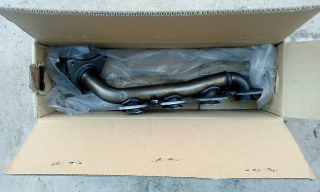
Выпускной коллектор на двигателях серии 2 uz и 3uz выполнен из стали. На двигателях серии 1 uz из чугунного сплава. С пробегом и возрастом требуется замена прокладок выпускного коллектора или коллектора целиком – появляются трещины.
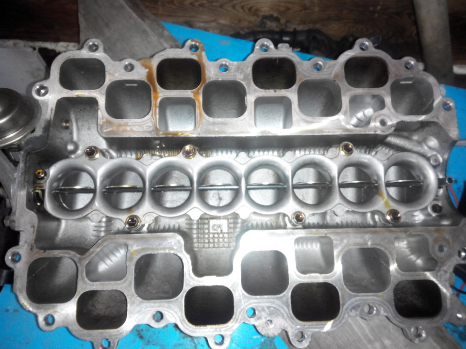
Демонтированный впускной коллектор. Обратите внимание на заслонки, расположенные по средине коллектора.
Все двигатели серии uz оснащены системой изменения геометрии впускного коллектора (ACIS)
Разберем детально принцип работы данной системы
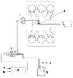
1 – исполнительный механизм; 2 – управляющий клапан системы изменения фаз газораспределения; 3 – к сглаживающему ресиверу; 4 – вакуумный клапан; 5 – вакуумный резервуар; 6 – электронный блок управления двигателя.
Принцип работы системы ACIS заключается в том, что блок управления двигателя, получая информацию с различных датчиков двигателя (датчик положения дроссельной заслонки, тахометра и т.д.) и в зависимости от конкретных условий работы закрывает или наоборот открывает заслонку, разделяющую впускной коллектор на две части. Вследствие чего увеличивается или уменьшается рабочая длинна впускного коллектора.
Выпускной коллектор требует от владельца автомобиля повышенного внимания. С пробегом существует вероятность самопроизвольного откручивания заслонок коллектора и попадания крепежных винтов, а так же самих заслонок в клапанный механизм и цилиндры двигателя. Попадания постороннего предмета в камеру сгорания двигателя в большинстве случаев потребует его замены или дорогостоящего ремонта
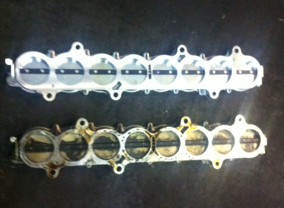
Заслонки воздушного коллектора
Разберем на примере одного из автомобилей, который пострадал от этой неисправности в декабре 2017г.
Lexus LS430 3 uz fe. Неисправность – попадание заслонки 7 цилиндра в клапанный механизм. К сожалению, повреждения оказались приговором для двигателя.
Заслонка впускного коллектора открутилась, попала в клапанный механизм, клапан остался в открытом положении, по нему ударил поршень, клапан сломало на несколько частей. Детали клапанного механизма попали в камеру сгорания. В итоге были повреждены – ГБЦ, поршень и гильза блока цилиндров.
Демонтаж впускного коллектора с двигателя 3uz fe
Отсутствуют некоторые винты крепления заслонок, а так же заслонка 7 цилиндра
Поломанный клапанный механизм
Поломанные стержни клапанов, извлеченные из камеры сгорания двигателя.
Поэтому, для предотвращения таких последствий раз в 150 000 – 200 000 крайне желательно проводить осмотр заслонок воздушного коллектора. При проведении подобных работ можно провести работы по профилактическому обслуживанию стартера ДВС, который находится в развале блока цилиндров.
4.0 Двигатель
Двигатель
Спецификации
Процедуры обслуживания двигателя, не требующие извлечения его из
автомобиля
Общие параметры
|
Характеристика |
Значение |
|
Обозначение двигателей |
|
|
8–цилиндровый (V8) бензиновый двигатель 4.7 л |
2UZ–FE |
|
6–цилиндровый (R6) турбодизельный двигатель 4.2 |
1HD–FTE |
|
Объем двигателя, л (см |
|
|
Бензиновый двигатель 2UZ–FE |
4.7 (4663) |
|
Дизельный двигатель 1HD–FTE |
4.2 (4164) |
|
Развиваемая мощность и крутящий момент, кВт@мин |
|
|
Бензиновый двигатель 2UZ–FE |
173@4800/434@3400 |
|
Дизельный двигатель 1HD–FTE |
150@3400/430@1400 – 3200 |
|
Нумерация цилиндров (считая со стороны привода ГРМ) (обратитесь к Настройки и текущее обслуживание автомобиля ) |
|
|
Двигатель 2UZ–FE |
|
|
Левый ряд цилиндров |
1–3–5–7 |
|
Правый ряд |
2–4–6–8 |
|
Двигатель 1HD–FTE |
1–2–3–4–5–6 |
|
Порядок зажигания |
|
|
Двигатель 2UZ–FE |
1–8–4–3–6–5–7–2 |
|
Двигатель 1HD–FTE |
1–4–2–6–3–5 |
|
Степень сжатия |
|
|
Двигатель 2UZ–FE |
9.6:1 |
|
Двигатель 1HD–FTE |
18.8:1 |
|
Материал блока цилиндров |
Чугун |
|
Материал головки(ок) цилиндров |
|
|
Двигатель 2UZ–FE |
Алюминий |
|
Двигатель 1HD–FTE |
Чугун |
|
Предельная допустимая неплоскостность |
|
|
Двигатель 1HD–FTE |
|
|
Головка цилиндров |
0.10 |
|
Впускной трубопровод |
0.15 |
|
Выпускные коллекторы |
0.50 |
|
Блок цилиндров |
0.07 |
|
Диаметр болтов крепления головок цилиндров двигателя 2UZ–FE на расстоянии |
|
|
Номинальное значение |
9.810 ÷ 9.960 |
|
Предельно допустимое значение |
9.700 |
|
Диаметр растяжимой части болтов крепления крышек подшипников коленчатых |
|
|
Номинальное значение |
10.760 ÷ 10.970 |
|
Предельно допустимое значение |
10.400 |
|
Давление масла при 3000 об/мин, бар |
|
|
Двигатель 2UZ–FE |
3.0 х 6.0 |
|
Двигатель 1HD–FTE |
2.5 х 6.1 |
|
Диаметр цилиндров х ход поршня, мм |
|
|
Двигатель 2UZ–FE |
94 х 84 |
|
Двигатель 1HD–FTE |
94 х 100 |
|
Степень сжатия |
|
|
Двигатель 2UZ–FE |
9.6:1 |
|
Двигатель 1HD–FTE |
18.8:1 |
Распределительные валы и сопутствующие компоненты
|
Характеристика |
Значение |
|
Диаметр подшипниковых шеек, мм |
|
|
2UZ–FE |
26.954 ÷ 26.970 |
|
1HD–FTE |
|
|
Шейка №1 |
34.969 ÷ 34.985 |
|
Остальные шейки |
27.986 ÷ 27.998 |
|
Зазоры в подшипниках, мм |
|
|
2UZ–FE |
|
|
Номинальное значение |
0.030 ÷ 0.067 |
|
Предельно допустимое значение |
0.10 |
|
1HD–FTE |
|
|
Номинальное значение |
|
|
Шейка №1 |
0.022 ÷ 0.074 |
|
Остальные шейки |
0.023 ÷ 0.075 |
|
Предельно допустимое значение |
0.100 |
|
Высота кулачков, мм |
|
|
2UZ–FE |
|
|
Номинальное значение |
|
|
Кулачки привода |
41.94 ÷42.04 |
|
Кулачки привода |
41.96 ÷ 42.06 |
|
Предельно допустимое значение |
|
|
Кулачки привода |
41.79 |
|
Кулачки привода |
41.91 |
|
1HD–FTE |
|
|
Номинальное значение |
|
|
Кулачки привода |
48.498 ÷ 48.598 |
|
Кулачки привода |
50.734 ÷ 50.834 |
|
Предельно допустимое значение |
|
|
Кулачки привода |
47.998 |
|
Кулачки привода |
50.234 |
|
Величина осевого люфта, мм |
|
|
2UZ–FE |
|
|
Номинальное значение |
|
|
Впускной вал |
0.040 ÷ 0.090 |
|
Выпускной вал |
0.040 ÷ 0.085 |
|
Предельно допустимое значение |
0.12 |
|
1HD–FTE |
|
|
Номинальное значение |
0.10 ÷ 0.20 |
|
Предельно допустимое значение |
0.30 |
|
Люфт зацепления шестерен распределительных валов, мм |
|
|
2UZ–FE |
|
|
Номинальное значение |
0.020 ÷ 0.200 |
|
Предельно допустимое значение |
0.30 |
|
Свободная длина разрыва в замке пружины шестерни распределительного |
|
|
2UZ–FE |
18.2 ÷ 18.8 |
|
Предельная допустимая величина бокового биения средней шейки, мм |
|
|
2UZ–FE |
0.08 |
|
1HD–FTE |
0.10 |
|
Величина выступания натяжителя газораспределительного ремня, мм |
|
|
2UZ–FE |
10.5 ÷ 11.5 |
|
1HD–FTE |
9.0 ÷ 9.8 |
|
Параметры гидротолкателей клапанов, мм |
|
|
2UZ–FE |
|
|
Наружный диаметр |
30.966 ÷ 30.976 |
|
Диаметр посадочного гнезда |
31.000 ÷ 31.016 |
|
Посадочный зазор |
|
|
Номинальное |
0.024 ÷ 0.050 |
|
Предельное допустимое |
0.07 |
|
1HD–FTE |
|
|
Наружный диаметр |
40.892 ÷ 40.902 |
|
Диаметр посадочного гнезда |
40.960 ÷ 40.980 |
|
Посадочный зазор |
|
|
Номинальное |
0.058 ÷ 0.083 |
|
Предельное допустимое |
0.10 |
Усилия затягивания резьбовых соединений, Нм
Бензиновый двигатель (2UZ–FE)
|
Тип соединения |
Значение |
|
Болты крепления крышек головок цилиндров |
6 |
|
Болты/гайки крепления впускного трубопровода |
18 |
|
Гайки крепления выпускных коллекторов |
44 |
|
Гайки крепления приемной трубы к коллектору |
62 |
|
Болты крепления теплозащитного экрана |
7.5 |
|
Болт крепления шкива коленчатого вала |
245 |
|
Болты крепления крышки №2 привода ГРМ |
16 |
|
Болты крепления крышки №3 привода ГРМ |
7.5 |
|
Болты крепления промежуточных роликов* |
35 |
|
Болт (106 мм) и гайки крепления натяжителя приводного ремня |
16 |
|
Болты крепления натяжителя газораспределительного ремня |
26 |
|
Болты крепления зубчатых колес распределительных валов |
108 |
|
Болты крепления кронштейна вентилятора |
|
|
Болты 12 мм |
16 |
|
Болты 14 мм |
32 |
|
Болты крепления крышек подшипников распределительных валов |
|
|
Болты 25 мм |
7.5 |
|
Остальные болты |
16 |
|
Болты крепления головок цилиндров |
|
|
Стадия 1 |
32 |
|
Стадия 2 |
Дотянуть еще на 90 град. |
|
Стадия 3 |
Дотянуть еще на 90 град. |
|
Болты крепления верхней части поддона картера |
|
|
Болты 10 мм |
7.5 |
|
Болты 12 мм |
28 |
|
Болты крепления верхней части поддона картера |
7.5 |
|
Болты крепления маслозаборника |
7.5 |
|
Болты крепления демпфирующей пластины |
7.5 |
|
Стяжные болты масляного насоса |
10 |
|
Болты крепления масляного насоса |
|
|
Болты 14 мм |
30 |
|
Остальные болты |
15 |
|
Болты крепления насоса ГУР |
17 |
|
Крепеж маслоохладителя |
18 |
|
Болты крепления маховика* |
83 |
|
Болты крепления приводного диска* |
|
|
Стадия 1 |
49 |
|
Стадия 2 |
Дотянуть еще на 90 град. |
|
Опоры подвески двигателя |
|
|
Болты крепления держателя заднего сальника коленчатого |
7.8 |
|
* Перед вворачиванием болта его резьбовую часть следует |
Дизельный двигатель (1HD–FTE)
|
Тип соединения |
Значение |
|
Болты крепления головки цилиндров |
|
|
Стадия 1 |
69 |
|
Стадия 2 |
Дотянуть еще на 90 град. |
|
Стадия 3 |
Дотянуть еще на 90 град. |
|
Болты крепления крышек подшипников распределительных валов |
25 |
|
Болты крепления задней крышки ремня привода ГРМ |
20 |
|
Болты крепления крышек головок цилиндров |
6.5 |
|
Крепеж заднего кронштейна двигателя |
39 |
|
Болты крепления сборки выпускного коллектора |
40 |
|
Болты крепления патрубка отвода ОЖ |
20 |
|
Гайки крепления впускного трубопровода |
20 |
|
Крепеж топливных трубок высокого давления |
25 |
|
Крепеж впускного патрубка к впускному трубопроводу |
|
|
Модели с системой EGR |
19.6 |
|
Модели без системы EGR |
|
|
С головками 10 мм |
7.5 |
|
С головками 12 мм |
20 |
|
Гайки крепления адаптера клапана EGR к выпускному коллектору |
40 |
|
Болты крепления кронштейна клапана EGR |
20 |
|
Болты крепления нижней крышки шатуна |
|
|
Стадия 1 |
37 |
|
Стадия 2 |
Дотянуть еще на 90 град. |
|
Болты крепления крышек коренных подшипников коленчатого вала |
|
|
Стадия 1 |
103 |
|
Стадия 2 |
Дотянуть еще на 90 град. |
|
Зубчатое колесо распределительного вала |
|
|
Ведомое |
98 |
|
Ведущее |
31 |
|
Шестерня привода ТНВД |
98 |
|
Промежуточная шестерня |
68 |
|
Шкив коленчатого вала |
430 |
|
Болты крепления крышки зубчатых колес |
20 |
|
Гайки крепления крышки масляного насоса |
39 |
|
Болты крепления маслопровода |
20 |
|
Пробка редукционного клапана масляного насоса |
42 |
|
Заливная пробка масляного насоса |
9 |
|
Обратный клапан маслоохладителя |
27 |
|
Предохранительный клапан маслоохладителя |
39 |
|
Гайки крепления крышки маслоохладителя |
20 |
| Крепеж маслоохладителя |
20 |
Процедуры общего и капитального ремонта двигателя (бензиновый двигатель
2UZ–FE)
Общие параметры
|
Характеристика |
Значение |
|
Компрессионное давление в цилиндрах при 250 об/мин, кГс/см |
|
|
Номинальное значение |
13.44 |
|
Минимальное допустимое значение |
9.94 |
|
Допустимая разница компрессионного давления в разных цилиндрах |
не более 0.98 |
Клапанный механизм
|
Характеристика |
Значение |
|
Высота цилиндрической части (пояска) тарелок клапанов, мм |
|
|
Номинальное значение |
|
|
Впускные клапаны |
1.25 |
|
Выпускные клапаны |
1.4 |
|
Предельное допустимое значение |
0.5 |
|
Диаметр стержней клапанов, мм |
|
|
Впускные клапаны |
5.470 ÷ 5.485 |
|
Выпускные клапаны |
5.465 ÷ 5.480 |
|
Зазор посадки стержней клапанов в направляющих втулках, мм |
|
|
Впускные клапаны |
|
|
Номинальное значение |
0.025 ÷ 0.060 |
|
Предельное допустимое значение |
0.08 |
|
Выпускные клапаны |
|
|
Номинальное значение |
0.030 ÷ 0.065 |
|
Предельное допустимое значение |
0.10 |
|
Фаска клапана, град |
44.5 |
|
Полная длина клапана, мм |
|
|
Впускные клапаны |
|
| Номинальное значение | 95.05 |
|
Коренные шейки коленчатого вала |
|
|
Диаметр постели коленчатого вала, мм |
|
|
Метка «1» |
71.000 ÷ 71.003 |
|
Метка «2» |
71.006 ÷ 71.012 |
|
Метка «3» |
71.012 ÷ 71.018 |
|
Диаметр коренных шеек, мм |
|
|
Метка «1» |
66.994 ÷ 67.000 |
|
Метка «2» |
66.988 ÷ 66.994 |
|
Метка «3» |
66.982 ÷ 66.988 |
|
Толщина вкладышей коренных подшипников, мм |
|
|
Метка «2» |
1.979 ÷ 1.982 |
|
Метка «3» |
1.982 ÷ 1.985 |
|
Метка «4» |
1.985 ÷ 1.988 |
|
Метка «5» |
1.988 ÷ 1.991 |
|
Метка «6» |
1.991 ÷ 1.994 |
|
Рабочий зазор в подшипниках, мм |
|
|
Номинальное значение |
0.036 ÷ 0.054 |
|
Ремонтный размер |
0.037 ÷ 0.077 |
|
Предельное допустимое рабочее |
0.100 |
|
Осевой люфт коленчатого вала, мм |
|
|
Номинальное значение |
0.040 ÷ 0.240 |
|
Предельное допустимое рабочее |
0.30 |
|
Толщина ремонтного упорного подшипника, мм |
2.930 ÷ 2.980 |
Блок и головка цилиндров
|
Характеристика |
Значение |
|
Диаметр цилиндра, мм |
|
|
Номинальный |
|
|
Метка «1» |
94.000 ÷ 94.010 |
|
Метка «2» |
94.010 ÷ 94.020 |
|
Метка «3» |
94.020 ÷ 94.030 |
|
Допустимый |
|
|
До 1–го ремонта |
94.23 |
|
До 2–го ремонта |
94.73 |
|
Диаметр сверления под направляющую втулку клапана, мм |
|
|
Номинальный |
11.504 ÷ 11.525 |
|
Ремонтный |
11.554 ÷ 11.575 |
|
Внутренний диаметр направляющей втулки, мм |
7.010 ÷ 7.030 |
|
Выступ втулки, мм |
17.5 ÷ 17.9 |
Поршни и поршневые кольца
|
Характеристика |
Значение |
|
Диаметр поршня (номинальное значение), мм |
|
|
Метка «1» |
93.845 ÷ 93.855 |
|
Метка «2» |
93.855 ÷ 93.865 |
|
Метка «3» |
93.865 ÷ 93.875 |
|
Выступ поршня из блока цилиндров, мм |
0.175 ÷ 0.425 |
|
Зазор посадки поршней в цилиндрах, мм |
|
|
Номинальное значение |
0.145 ÷ 0.165 |
|
Предельное допустимое рабочее значение |
0.215 |
|
Зазоры в замках поршневых колец, мм |
|
|
Верхнее компрессионное кольцо |
|
|
Номинальное значение |
0.27 ÷ 0.47 |
|
Предельное допустимое значение |
0.85 |
|
Второе компрессионное кольцо |
|
|
Номинальное значение |
0.40 ÷ 0.65 |
|
Предельное допустимое значение |
0.90 |
|
Маслосъемное кольцо |
|
|
Номинальное значение |
0.20 ÷ 0.50 |
|
Предельное допустимое значение |
0.88 |
|
Зазоры посадки колец в канавках поршней, мм |
|
|
Верхнее компрессионное кольцо |
0.050 ÷ 0.095 |
|
Второе компрессионное кольцо |
0.050 ÷ 0.100 |
|
Маслосъемное кольцо |
0.030 ÷ 0.070 |
|
Максимально допустимый зазор |
0.20 |
Бензиновый двигатель 1UZ-FE был разработан и производился компанией Toyota с 1989 по 2004 г. Мотор использовался на премиальных седанах и крупных внедорожниках. Удачная конструкция позволила 1UZ-FE входить с 1998 по 2000 г. в десятку лучших двигателей по оценке Ward’s AutoWorld.
ДВС 1UZ-FE – представитель семейства 8-цилиндровых моторов, в которое входили 2UZ-FE и 3UZ-FE, отличавшиеся техническими параметрами. Двигатели были частично унифицированы, что позволило снизить расходы на освоение производства.
Последним представителем семейства на конвейере стал 3UZ-FE, который собирался вплоть до 2013 г. При разработке двигателя учитывался опыт создания гоночных двигателей для американской серии Cart/IRL. На фото показан общий вид агрегата 1UZ-FE, снятого с машины.

В 1997 г. компания Toyota представила модификацию 1UZ-FE под обозначением FV2400-2TC, рассчитанную на применение на легких самолетах. Двигатель оснащался двойным наддувом и развивал 360 л. с. Разработка модели велась в партнерстве с компанией Hamilton Standard.
В 1998 г. была представлена морская версия 1UZ-FE мощностью 304 л. с. (модель VT300i), которая предлагалась для монтажа на моторные лодки.
Особенности конструкции
Двигатель 1UZ-FE оснащался 8-цилиндровым блоком, отлитым из алюминиевого сплава. Гильзы из серого чугуна с термической и механической обработкой были выполнены в виде единой детали для каждого ряда цилиндров и залиты в материал блока.
Угол развала составлял 90⁰. Для установки шатунов на единой шейке коленвала ряды цилиндров имели небольшое смещение. Головки из алюминия включали постели для пары распределительных валов, концерн Toyota использовал на моторе 1UZ-FE 4-клапанную схему газораспределения.
Диаметр цилиндра – 87,5 мм. Двигатели других моделей отличались увеличенными габаритами и объемом. Система охлаждения жидкостного типа оснащалась вентилятором с вязкостной муфтой, позволявшей плавно регулировать обороты крыльчатки.
Распределительный вал впускных клапанов имел ременной привод, который приводил во вращение и помпу системы охлаждения. Второй распределительный вал получал момент при помощи шестерен.

Двигатель претерпел несколько этапов модернизации. С 1995 г. стала использоваться другая шатунно-поршневая группа, позволившая поднять степень сжатия и улучшить характеристики.
Ранняя версия 1UZ-FE не оснащалась регулятором фаз, который был внедрен только в 1997 г. на валах клапанов впуска с очередным повышением степени сжатия. Для всех моделей 1UZ-FE использовался бензин с октановым числом не ниже 95 единиц.


Для подачи топлива использовалась система многоточечного секвенционального впрыска MPFI (с 1995 г. стала использоваться система попарно-параллельной подачи SFI). Конструкция выхлопного тракта зависит от года выпуска.
Для снижения токсичности газов на 1UZ-FE устанавливали каталитические нейтрализаторы и датчики концентрации кислорода. Предусматривалась система рециркуляции части отработавших газов. Последние версии 1UZ-FE соответствовали международным нормативам Евро-3.
Технические характеристики
1UZ-FE вытеснил с конвейера 5V и был рассчитан на рынок Северной Америки, а также шел на модели автомобилей премиального класса для Японии. В конструкции мотора изначально использовался механический дроссель, который с 1997 г. заменила электронная заслонка.
Следует учесть, что ранние моторы без регулятора фаз не боятся обрыва ремня привода ГРМ. После введения регулятора VVT-i изменилась конструкция поршней, которые сталкиваются с тарелками клапанов при разрушении ремня.
Характеристики 1UZ-FE:
- рабочий объем двигателя – 3969 см³;
- ход поршня – 82,5 мм;
- вес силового агрегата (с заправкой маслом) – от 165 до 220 кг;
- емкость системы смазки – 5 л.
Параметры 1UZ-FE зависят от года выпуска. Наименьшую мощность и момент имеют двигатели первых лет выпуска. Характеристики приведены в сводной таблице.
| Год выпуска | Степень сжатия | Мощность, л. с. | Частота вращения, об/мин | Момент, н*м | Частота вращения, об/мин |
| 1989-1995 | 10,0 | 256 | 5400 | 353 | 4400 |
| 1995-1997 | 10,4 | 261 | 5400 | 365 | 4400 |
| 1997-2004 | 10,5 | 290 | 5900 | 407 | 4100 |
| Специальная модель для Lexus GS400 | 10,5 | 300 | 6000 | 420 | 4000 |
По мере модернизации пик мощности стал уходить в зону повышенных оборотов. Максимальный момент при частоте вращения от 4000 об/мин требует раскручивать коленчатый вал при разгоне, что негативно сказывается на расходе топлива.
Расход топлива 1UZ-FE
Мотор 1UZ-FE отличается большим объемом, негативно сказывающимся на экономичности. Расход топлива зависит от множества факторов. Помимо технического состояния двигателя на затраты бензина влияет:
- вес автомобиля;
- стиль управления;
- погодные условия.
Например, версия 1UZ-FE non VVTi на автомобиле Toyota Celsior с кузовом XF10 расходовала в смешанном цикле 14,1 л на 100 км (замер по японской методике 10/15). Установка регулятора фаз на серии Celsior с кузовом XF20 позволила снизить расход в комбинированном режиме до 11,8 л на 100 км.

На какие машины ставился силовой агрегат Toyota 1UZ-FE
1UZ-FE предназначались для:
- Lexus LS 400 и SC 400;
- Toyota Crown, Crown Majesta и Celsior, Soarer и Aristo.
- Toyota HiAce HiMedic Ambulance (медицинский микроавтобус для поставок в Японию).


1UZ-FE часто используется при модернизации автомобилей марок Mitsubishi и Nissan. Для установки требуется доработка моторного отсека и трансмиссии.
Практикуется доработка легковых и грузовых автомобилей ГАЗ – вместо штатного мотора с механической коробкой ставят 1UZ-FE с АКПП. Встречаются модернизированные микроавтобусы и внедорожники УАЗ, которым на бездорожье и трассе не хватает мощности оригинального двигателя.
Варианты тюнинга
Прочная конструкция блока и поршневой группы позволяет форсировать двигатели 1UZ-FE. Для доработки возможна установка механического компрессора (например, Eaton M90) с оригинальным коллектором впуска и аппаратурой для корректировки подачи топлива. С двигателя снимают нейтрализаторы и ставят выпускные коллекторы с пониженным сопротивлением потоку.
Замеры на стендах показывают, что повышение давления на впуске до 0,4 бар при неизменной степени сжатия позволяет получить до 330 л. с. с одновременным выравниванием кривой крутящего момента.
Дальнейшая модернизация 1UZ-FE предполагает повышение давления наддува до 0,6-0,7 бар с использованием других головок для сокращения степени сжатия и другой шатунно-поршневой группы. При использовании охладителя сжатого воздуха и бензина А-98 мощность доходит до 400 л. с.
Для большего повышения характеристик необходима кардинальная перестройка двигателя 1UZ-FE с установкой турбины с клапаном сброса давления. Требуется применение охладителя воздуха, модернизированной системы смазки, установки теплоизоляции на патрубки. Вместо штатной электроники ставят модернизированный контроллер.
Мощность доходит до 450 л. с. без сильного снижения ресурса. При установке двойного наддува двигатель способен развить до 500 л. с., но увеличивается и риск выхода агрегата из строя.
Достоинства и недостатки
большой ресурс (до 500 тыс. км);
возможность наращивания характеристик путем применения турбин;
отсутствие проблем с подбором запасных частей;
простота поиска контрактного двигателя.
нескромный расход топлива (до 25-39 л в условиях города и интенсивного нажатия на педаль газа);
повышенный ежегодный налог (двигатель с блоком V8 выпадает из «льготной» категории до 249 л. с.);
использование для привода двух валов DOHC зубчатого ремня, при разрушении которого загибаются стержни клапанов (проблема не распространяется на моторы без регулятора фаз);
необходимость периодической настройки клапанов комплектами «стаканчиков» (на 1UZ-FE не предусматривались автоматические компенсаторы зазоров).
Регламент обслуживания мотора 1UZ-FE
Ключевые требования по содержанию 1UZ-FE:
- замена моторного масла и фильтра – через каждые 8-10 тыс. км (в зависимости от условий эксплуатации);
- ресурс оригинального заводского антифриза Toyota – 150 тыс. км;
- замена ремня ГРМ с натяжными роликами – через 120-150 тыс. км;
- ресурс помпы охлаждающей жидкости – около 150 тыс. км;
- регулировка зазоров клапанов – через 120-150 тыс. км (при установке газобаллонного оборудования проверку лучше проводить в 2-3 раза чаще);
- ресурс свечей зажигания – около 80 тыс. км (может меняться в зависимости от состояния электродов);
- осмотр и установка новых заслонок корректировки протяженности впускного коллектора – через 150-200 тыс. км.

Следую, но не всегда
100%
Проголосовало: 1
Обзор неисправностей двигателя 1UZ-FE
Поскольку большая часть 1UZ-FE имеет пробеги свыше 200 тыс. км, то владельцы часто сталкиваются с поломкой клапанов, отвечающих за работу регулятора фаз (стоят в каждой головке). При износе клапана регулятор работает некорректно, что сказывается на мощности и эластичности двигателя.
Чугунные коллекторы выпуска на 1UZ-FE могут растрескаться из-за перепадов температуры, не отличается надежностью система ACIS для изменения длины впуска. Сорванные заслонки могут попасть под тарелки клапанов, что приводит к столкновению клапана с поршнем.
Осевая нагрузка на вал помпы приводит к появлению течи, антифриз негативно влияет на ремень ГРМ и ролики (обнаружить мелкие капли жидкости невозможно из-за лобового щитка).
Ремонт двигателя Toyota 1UZ-FE
Для ремонта не требуется специальная оснастка, но необходимо подготовить документацию по разборке и сборке. Например, для замены ременного привода ГРМ потребуется снять облицовку и блок радиаторов. Затем понадобится убрать ремень навесного оборудования и снять шкив с носка коленчатого вала, используя оправку для фиксации от прокручивания.
Из-за плотной компоновки понадобится демонтировать насос усилителя руля, генератор. Для доступа к крышкам головок блоков необходимо снять дроссельный узел. Разборка занимает много времени и требует от мастера внимательности. После снятия крышек рекомендуется установить новые прокладки колодцев для свечей и сменить кольца в муфте регулятора фаз.
В среднем процедура замены привода ГРМ с регулировкой клапанов и заменой резинотехнических изделий занимает 10 часов рабочего времени. В видео продемонстрирована часть процесса обслуживания механизма ГРМ двигателя 1UZ-FE.
Свап 1UZ-FE
Установка 1UZ-FE вместо родного двигателя требует доработки точек опор в моторном отсеке. Также необходимо добавить систему подачи топлива под давлением, радиаторы, воздушный фильтр, предусмотреть место для аккумулятора. При свапе 1UZ-FE требуется установка контроллера, трудоемкость процедуры зависит от модели автомобиля.

Двигатель 1UZ-FE относится к категории массовых моделей и часто встречается на вторичном рынке. Заложенный при разработке запас прочности позволяет оставаться в строю экземплярам первых лет выпуска. Существовала даже гоночная 600-сильная версия для участия в гонках в Ле-Мане, которая не принесла компании Toyota положительных эмоций.
Сохраните статью в закладках, чтобы не потерять полезные рекомендации.
Регистрируясь на данном ресурсе Вы соглашаетесь с действующими Правилами форума и обязуетесь их соблюдать.
Незнание правил не освобождает Вас от наказания за их нарушение!
На форуме действует ряд ограничений для новых пользователей: запрещено заниматься торговлей, устанавливать автар и подпись, принимать участие в опросах, личный ящик ограничен 10-ю сообщениями.
Для снятия ограничений Вам надо оставить на форуме более 10 сообщений, а также с момента вашей регистрации должно пройти не менее 30 дней.
Для участников клуба доступна различная клубная атрибутика: рамки, наклейки, футболки, толстовки, кружки, карты и т.д. Причем некоторые виды атрибутики распространяются бесплатно на встречах. Более подробную информацию узнавайте в своем региональном разделе или теме. Также если Вы хотите заниматься клубной атрибутикой в своем городе, то напишите об этом администрации.
С уважением, администрация форума TourerV.ru
ENGINE — 1UZ–FE ENGINE
81
ENGINE
1UZ–FE ENGINE
DESCRIPTION
The 1UZ–FE engine is a V–8, 4.0–liter, 32–valve DOHC engine designed exclusively for the luxury LS400 sedan.
Incorporating the state–of–the–art technology, this engine implements high–speed performance and utility at a high
level providing an exciting feeling of a very smooth acceleration response to the pedal operation. With thorough
analysis, design and precisely controlled manufacturing, major component parts have been improved to achieve very
low vibration and noise level.
The engine operation is accurately–controlled by the ECU (Electronic Control Unit) and maintains peak performance
and efficiency at all times.
ENGINE — 1UZ–FE ENGINE
82
ENGINE SPECIFICATIONS AND PERFORMANCE CURVE
Engine
Item
No. of Cyls. & Arrangement
1UZ FE
1UZ–FE
8–Cylinder, V Type
Valve Mechanism
32–Valve, DOHC, Belt & Gear Drive
Combustion Chamber
Pentroof Type
Manifolds
Cross–flow
Displacement
cu. in. (cc)
Bore x Stroke
in. (mm)
Compression Ratio
Firing Order
242.1 (3,969)
3.44 x 3.25 (87.5 x 82.5)
10.0 : 1
1–8–4–3–6–5–7–2
Max. Output (SAE–NET)
250 HP @ 5,600 rpm
Max. Torque (SAE–NET)
260 ft.lbs @ 4,400 rpm
Fuel Octane Number (RON)
Oil Grade*
*
Refer to the next page for detail.
96
API SG, EC–II
ENGINE — 1UZ–FE ENGINE
83
*NOTE: Engine oil selection
Use API (American Petroleum Institute) grade SG, Energy–Conserving II multigrade engine oil.
Recommended viscosity is as follows, with SAE 5W–30 being the preferred engine oil for the 1UZ–FE
engine.
Recommended Viscosity (SAE)
A label is added to the oil filler cap and some oil containers to help you select the oil you should use.
The top portion of the label shows the oil quality by API designations such as SG. The center portion of the label shows
the SAE viscosity grade, such as SAE 5W–30.
“Energy–Conserving II” shown in the lower portion, indicates that the oil has fuel–saving capabilities.
Oil Identification Label
Oils marked “Energy–Conserving II” will have higher fuel–saving capabilities than oils marked
“Energy–Conserving.”
ENGINE — 1UZ–FE ENGINE
84
FEATURES OF 1UZ–FE ENGINE
Features of the 1UZ–FE engine are shown in the following list:
Features
Contents
Compact DOHC, 32–valve, center–firing and high compression ratio
combustion chamber implements a high combustion efficiency.
High Performance
ECU–controlled precise engine operation.
Reduced intake and exhaust losses resulting from large–diameter intake duct,
air flow meter, dual exhaust system, etc.
Reduced cylinder head size by the adoption of a scissors gear mechanism.
Lightweight and Compact Design Cylinder block and oil pan made of aluminum alloy.
Compact, lightweight accessory drive system by means of serpentine, single
belt and bracketless accessory installation.
Low Noise and Vibration
Serviceability
Outer shim type valve lifter.
Auto tensioners for timing belt and V–ribbed belt.
Engine oil level sensor.
High Reliability
Use of an aluminum oil pan having an integral stiffener.
Aluminum engine mount brackets and liquid–filled compound engine mounts.
Silent start type three–stage temperature–controlled auto–coupling fan.
Rigid and accurately balanced crankshaft assembly.
Auto tensioners for timing belt and V–ribbed belt.
Thin cast–iron liner press–fit in aluminum cylinder block.
Highly durable timing belt and auto tensioner.
Plastic region tightening bolts in major parts (cylinder head bolts, crankshaft
bearing cap bolts, connecting rod cap bolts).
ENGINE — 1UZ–FE ENGINE
85
ENGINE
1. Cylinder Head
The cylinder head is made of aluminum and has intake and exhaust ports in a cross–flow arrangement. The intake
ports are on the inside and the exhaust ports on the outside of the left and right banks respectively.
The cylinder heads are compact even for a DOHC engine. The pitch of the intake and exhaust camshafts is
shortened and the valve angle is narrowed to 2133′.
The left and right banks of cylinder heads are common in configuration.
NOTICE
When the cylinder heads are disassembled for servicing, be sure to assemble each cylinder head to the correct right
or left bank. The camshaft may seize if they are assembled incorrectly.
Pentroof type combustion chamber with four valves is used.
The squish area guides the air–fuel mixture to the center of the combustion chamber to increase the combustion
speed and thus maintain a stable engine operation.
Plastic region tightening bolts, having a good axial tension stability, are used for securing the cylinder heads to
the block.
NOTE:
When reusing the cylinder head bolts, make sure the diameter at the thread is not less than 0.378 in. (9.6 mm).
It will be necessary to replace them with new ones if the diameter is less than specification.
ENGINE — 1UZ–FE ENGINE
86
2. Cylinder Block
The cylinder block has a bank angle of 90, a bank offset of 0.827 in. (21 mm) and a bore pitch of 4.15 in. (105.5
mm), resulting in a compact block in its length and width even for its displacement.
Lightweight aluminum alloy is used for the cylinder block.
A thin cast–iron liner is press–fit inside the cylinder to ensure an added reliability.
NOTICE
Never attempt to machine the cylinder because it has a thin 0.08 in. (2 mm) liner inside.
Part of the volute chamber of the water pump and the water by–pass passage are incorporated into the cylinder
block to shorten the engine length.
Installation bosses of the two knock sensors are located on the inner side of left and right banks.
The plastic region tightening bolts are used for the crankshaft bearing caps.
NOTE:
When reusing the crankshaft bearing cap bolts, make sure the diameter at the thread is not less than 0.291
in. (7.4 mm). It will be necessary to replace them with new ones if the diameter is less than specification.
The starter is located inside the V–bank.
To install a local engine block heater, first remove the cover plate shown in the “A” view drawing below.
ENGINE — 1UZ–FE ENGINE
87
NOTICE
When fitting the crankshaft bearing cap, always tighten
bearing.
first and
next in order to obtain roundness of the
ENGINE — 1UZ–FE ENGINE
88
3. Piston
Steel struts are used to control thermal
expansion.
The skirt of each piston is striation finished
(finely grooved) for maintaining
lubrication and reducing friction loss.
proper
The piston has a weight–adjusting boss to
minimize fluctuation of weight among pistons
and balance the engine assembly.
Piston pins are the full–floating type and are
held in place with snap rings.
4. Piston Ring
Each surface of the compression ring No. 1 and
the oil ring side rail is nitrified to prevent an
increase of oil consumption and blow–by gas as
the time elapses.
ENGINE — 1UZ–FE ENGINE
5. Connecting Rod
The sintered and forged connecting rod is very
rigid and has little weight fluctuation.
A weight–adjusting boss is provided at the big
end to reduce fluctuation of weight and balance
the engine assembly.
The connecting rod cap is held by plastic region
tightening bolts.
NOTE:
When reusing the connecting rod cap bolts,
if the diameter at the thread is less than
0.275 in. (7.0 mm), it is necessary to
replace them with new ones.
The connecting rods for the right and left banks
are placed in opposite directions with the outer
marks facing the crankshaft.
89
ENGINE — 1UZ–FE ENGINE
90
6. Crankshaft and Crankshaft Bearings
A forged crankshaft with five main journals, four connecting rod pins and eight balance weights is used.
Connecting rod pins and journals are induction–hardened to ensure an added reliability.
Bearings are made of kelmet.
Crankshaft bearings are selected carefully according to the measured diameters of the crank journal and cylinder
block journal holes.
NOTE:
The diameter of the crank journal and the cylinder block journal hole is indicated at the places shown below.
ENGINE — 1UZ–FE ENGINE
NOTE:
91
Numbers of the crankshaft and pistons are shown on the right side.
Crankshaft angles and engine strokes (intake, compression, combustion and exhaust) are shown in the table below.
The firing order is 1–8–4–3–6–5–7–2.
ENGINE — 1UZ–FE ENGINE
92
VALVE MECHANISM
1. General
Each cylinder has two intake valves and two exhaust valves.
The valves are directly opened and closed by four camshafts.
The intake camshafts are driven by a timing belt, while the exhaust camshafts are driven through gears on the
intake camshafts.
Use of outer shim type valve lifters makes it easy to adjust the valve clearance without removing the camshaft.
ENGINE — 1UZ–FE ENGINE
93
2. Camshafts
The exhaust camshafts are driven by gears on the intake camshafts. The scissors gear mechanism has been used
on the exhaust camshaft to control backlash and reduce gear noise.
The camshaft journals and camshaft driven gear are lubricated by oil supplied to an oil passage in the center of
the camshaft. Supply of oil from the cylinder heads to the camshafts is continuous, to prevent fluctuations in the
oil pressure.
The cast iron camshafts are used. The cam nose is chill treated.
“T” type oil seals are used.
NOTICE
Be sure to follow the disassembly and reassembling procedures as directed in the Repair Manual to avoid possibility
of damaging the cylinder head or camshaft timing gears (drive, driven and subgears).
94
ENGINE — 1UZ–FE ENGINE
—REFERENCE—
Scissors Gear Mechanism
To prevent the tooth surfaces of gears from seizing or being damaged when the gears are engaged, they are
designed to have backlash. However, backlash generates noise when changes in torque occur. The scissors gear
mechanism is one means of preventing this noise. The scissors gear mechanism uses a subgear with the same
number of teeth as the drive gear and is attached to the gear on the driven side. Through the reaction force of the
scissors spring, these two gears act to pinch the drive gear, reducing backlash to zero and eliminating gear noise.
ENGINE — 1UZ–FE ENGINE
3. Valve Lifter and Valve Adjusting Shims
Aluminum alloy valve lifters are used.
The valve adjusting shims used are of the outer
shim type and are located on top of the valve
lifters. It is not necessary to remove the
camshafts in order to replace the shims when the
valve clearance is adjusted.
NOTE:
(Method for replacing valve shims)
Push down the valve lifter using an SST
(Special Service Tool) to make a gap
between the camshaft and the valve lifter.
Direct compressed air from an air gun to the
service hole in the valve adjusting shim to
float the shim and remove it using a
magnetic finger. Be sure to direct the air
gun carefully so that you do not blow the
shim away.
4. Timing Pulleys and Belt
An auto–tensioner is made up of a spring and oil
damper, and maintains proper timing belt
tension at all times. The auto–tensioner
suppresses noise generated by the timing belt.
The timing belt has high heat resistance and
durability.
The tooth profile of the timing belt is shown at
the right. This design ensures a quiet operation
and high–load transmission.
95
ENGINE — 1UZ–FE ENGINE
96
LUBRICATION SYSTEM
1. General
The lubrication is fully pressurized and all oil passes through an oil filter.
The oil pump is a trochoid gear type and is directly driven by the crankshaft.
ENGINE — 1UZ–FE ENGINE
2. Oil Pan
The oil pan is made up of two pieces. No. 1 oil
pan is made of aluminum alloy and No. 2 oil pan
is made of steel.
The upper oil pan section is secured to the
cylinder block and the torque converter
housing, increasing rigidity.
The baffle plate controls the oil flow between
the two oil pans when the vehicle is turning or
is running along rough roads, etc.
An oil lever sensor is provided in the oil pan for
efficient servicing.
When the oil level falls below the specified
level, the oil level sensor causes the low engine
oil level warning light inside the combination
meter to light up.
97
ENGINE — 1UZ–FE ENGINE
98
COOLING SYSTEM
1. Cooling Circuit
The cooling system is a pressurized, forced–circulation type.
A thermostat, having a bypass valve, is located on the water pump inlet side of the cooling circuit. As the coolant
temperature rises, the thermostat opens and the bypass valve closes, so the system maintains suitable temperature
distribution in the cylinder head.
A gauge coolant temperature sender, coolant temperature sensor, start injector time switch for the EFI (Electronic
Fuel Injection) and BVSV (Bimetal Vacuum Switching Valve) for charcoal canister control are fitted to the front
water joint.
The rear water joint has bypass outlet ports for heating the throttle body, cooling the EGR valve and hot water
for the heater.
ENGINE — 1UZ–FE ENGINE
99
2. Water Pump
The water pump has two volute chambers, and
circulates coolant uniformly to the left and right
banks of the cylinder block.
The water pump is driven by the back of the
timing belt.
The rotor is made of resin.
3. Reservoir Tank
A pressurized valve is fitted to the reservoir.
A coolant level sensor is provided for efficient servicing.
When the coolant level falls below the specified level, the coolant level sensor causes the low engine coolant level
warning light inside the combination meter to light up.
CAUTIONS
1.
Never remove the cap while it is hot because the reservoir is also pressurized.
2.
Engine coolant is replenished from the reservoir. To do so, first loosen the plug at the top of the inlet housing
(shown on Page 98) to bleed air out of the cooling system. Be sure that the system is filled with coolant
completely.
ENGINE — 1UZ–FE ENGINE
100
4. Coupling Fan
A three stage temperature–controlled auto
coupling fan is used.
The speed of the coupling fan changes in three
stages based on the temperature of the air
passing through the radiator.
This keeps the fan speed low when the
temperature is low, improving warm–up
performance and reducing fan noise.
The fan speed is high when the engine
temperature is high, improving the cooling
performance.
Since part of the oil in the coupling fan is stored
in the back storage chamber, the amount of oil
in the operating chamber decreases at engine
start. Oil resistance and the fan speed are
reduced as a result immediately after engine
start.
The oil stored in the back storage chamber
gradually flows into the operating chamber as
the coupling fan keeps revolving. It eventually
flows entirely into the operating chamber.
ENGINE — 1UZ–FE ENGINE
101
INTAKE AND EXHAUST SYSTEM
1. Air Cleaner
The air cleaner case and cap are made of resin and have a large filtering capacity for the large engine displacement.
The air cleaner element is a low air resistance type and allows the air to pass through it very smoothly.
2. Intake Air Resonator
A resonator is used to reduce the intake air noise.
The resonator is made of resin. The air passage and resonator chamber are formed separately. The resonator
chamber is of the dual mode type and is separated by a partition.
ENGINE — 1UZ–FE ENGINE
102
3. Intake Air Chamber
The EGR and ISC (Idle Speed Control) passages
are attached to the intake air chamber.
The start injector is located at the center of the
intake air chamber so that fuel is distributed
evenly to all cylinders.
4. Intake Manifold
Ports are crossed to increase the port length and
inertia effects of the intake air.
ENGINE — 1UZ–FE ENGINE
103
5. Exhaust Manifold
Both exhaust manifolds are made of stainless steel.
The exhaust manifolds are covered with heat insulators to protect the surrounding parts from exhaust heat.
6. Exhaust Pipe
The stainless steel exhaust pipe consists of three sections; the front, center and tail. The center section is single
pipe while the front and tail are dual pipes to reduce exhaust resistance.
The catalyst converters (start and main) are of the monolithic type three–way catalysts.
The main catalyst converter is newly developed and has a high performance.
Large mufflers (main and sub) effectively reduce noise and exhaust pressure from the large capacity engine.
*
Applicable only to the California specification vehicles. Refer to page 161 for detail.
ENGINE — 1UZ–FE ENGINE
104
SERPENTINE BELT DRIVE SYSTEM
The serpentine belt drive system drives accessory components with a single V–ribbed belt. It reduces the overall
engine length, weight and number of engine parts.
An automatic tensioner eliminates the need for tension adjustment.
The arm is pushed by the tension spring in a
clockwise rotation direction always centering
around “Z”.
The pulley’s center of rotation is bolted to the
arm.
For this reason, when the belt stretches with
time, the pulley center of rotation rotates to the
right in an arc around “Z” with the arm. Thus the
belt tension is always maintained appropriately.
NOTICE
Check the indicator mark. If it is outside the
operation range, replace the belt.
When a new belt is installed, the graduations
must be in the area indicated by “A” in the
picture.
ENGINE — 1UZ–FE ENGINE
105
ENGINE MOUNTING
1. General
Liquid–filled compound engine mounts are fitted on both sides of the engine to reduce vibration and noise at all
speeds.
The aluminum engine mounting brackets reduce vibration and noise and minimize the total engine weight.
2. Liquid–Filled Compound Engine Mount
The engine mount combines rubber with liquid
filled chambers.
The fluid flows between upper and lower chambers
through an orifice.
In addition to vibrations being absorbed by the
rubber mounting, low frequency vibration is
absorbed by the fluid flowing through the orifice.
Also, by decreasing the elasticity of the rubber, the
dynamic spring constant has been reduced,
providing greater noise reduction in the case of high
frequency vibrations.
ENGINE — 1UZ–FE ENGINE
106
STARTING SYSTEM
1. Starter
The starter output is 2.0 KW and is located
inside the V–bank of the cylinder block.
CHARGING SYSTEM
1. Alternator
The IC regulated alternator has a large output of
1200 watts to produce enough electricity for the
electric load.
The alternator is fitted directly (without
brackets) to the cylinder block.
ENGINE — 1UZ–FE ENGINE
107
ENGINE MOUNTING
1. General
Engine control system uses an ECU (Electronic Control Unit) with a built–in microprocessor. Stored inside the ECU
is the data for fuel injection duration, ignition timing and idling speed, etc. which are matched with the various engine
conditions as well as programs for calculation. The ECU utilizes these data and signals from the various sensors in
the vehicle and makes calculations with the stored programs to determine fuel injection duration, ignition timing and
idling speed, etc., and outputs control signals to the respective actuators which control operation.
The engine ECU and transmission ECU are integrated into one and the ECU is called the engine and transmission
ECU. The engine control system for the 1UZ–FE engine has the following functions:
EFI (Electronic Fuel Injection)
The ECU determines the fuel injection duration according to intake air volume, engine speed, coolant temperature
and other signals and sends control signals to the fuel injectors. Also, this fuel injection duration is the basis for
deciding the fuel injection timing. The fuel injection system in the 1UZ–FE engine is a four group injection system
which injects fuel simultaneously into two cylinders once every two engine revolutions.
ESA (Electronic Spark Advance)
The ECU determines the amount of ignition advance over the initial set timing of the distributor by the intake air
volume, engine speed, coolant temperature and other signal and sends control signals to the igniters. Also, based on
signals from the knock sensors, the ECU controls the ignition timing at the optimum in accordance with the gasoline’s
octane value.
ISC (Idle Speed Control)
By means of engine speed signals and coolant temperature signals, the ECU sends control signals to the ISC valve
so that the actual idling speed becomes the same as the target idling speed stored in the ECU. Also, while the engine
is warming up, the ECU, based on coolant temperature signals, sends controls signals to the ISC value to control
engine speed to fast idle.
EGR (Exhaust Gas Recirculation) CUT CONTROL
The ECU sends signals to the EGR VSV to cut the EGR based on coolant temperature, engine speed, neutral start
switch or intake air volume signals. This system maintains drivability at low coolant temperature, under light or heavy
load conditions, or at high engine speed, etc.
FUEL PRESSURE CONTROL
The ECU sends signals to the pressure regulator VSV based on coolant temperature, intake air temperature, vehicle
speed and engine start signals, and increases the fuel pressure. This system maintains restartability and idling stability
when the engine is hot.
FUEL PUMP SPEED CONTROL
The ECU, based on fuel injection duration, sends control signals to the fuel pump control relay to control the fuel
pump speed. That is, when the engine requires a large volume of fuel, the fuel pump turns at high speeds and when
only a small volume of fuel is required, the pump turns at low speeds.
108
ENGINE — 1UZ–FE ENGINE
OXYGEN SENSOR HEATER CONTROL
Based on the intake air volume, engine start and coolant temperature signals, the ECU sends control signals to the
oxygen sensor heater. This system maintains the oxygen sensor at the appropriate temperature in order to improve
the detecting accuracy of oxygen concentration in the exhaust gas.
AIR CONDITIONER CONTROL
Based on the air conditioner switch signal from the air conditioner ECU, the ECU sends control signals to the
magnetic clutch of the air conditioner compressor. This system, the magnetic clutch operation, is delayed for a
predetermined period after the air conditioner switch is turned on.
DIAGNOSIS
The ECU is constantly monitoring signals from each sensor. If a malfunction occurs with the signals, the CHECK
ENGINE lamp on the combination meter lights up and informs the driver of the malfunction.
The content of the malfunction is stored in code in the ECU and when the TE1 and E1 terminals in the check connector
or TDCL are connected, the ECU outputs the trouble code by flashing the CHECK ENGINE lamp.
FAIL–SAFE
If the ECU judges from the signals from each sensor that there is a malfunction, it continues the engine operation using
its own data or it stops the engine.
ENGINE — 1UZ–FE ENGINE
2. Construction
The engine control system can be broadly divided into three groups: the ECU, the sensor and the actuators.
1
*2
Applicable only to California specification vehicles.
Applicable only to vehicles equipped with the optional TRAC (Traction Control) system
109
110
ENGINE — 1UZ–FE ENGINE
3. Summary of Engine Control System
The following list summarizes each system and control composing engine control system of the 1UZ–FE engine and
types of the related sensors, ECU and others.
*1: Applicable only to California specification vehicles.
*2: Applicable only to vehicles equipped with the optional TRAC (Traction Control) system
ENGINE — 1UZ–FE ENGINE
4. Engine Control System Diagram
*1: Applicable only to California specification vehicles.
*2: Applicable only to vehicles equipped with the optional TRAC (Traction Control) system
111
112
ENGINE — 1UZ–FE ENGINE
5. Arrangement of Engine Control System Components
ENGINE — 1UZ–FE ENGINE
113
6. EFI (Electronic Fuel Injection)
The EFI system consists of the following three major systems:
1) Fuel System
2) Air Induction System
3) Electronic Control System
Fuel System
1) General
Fuel is pumped under pressure by the electric fuel pump from the fuel tank, through the fuel filter, to the injectors
and the cold start injector.
The pressure regulator controls the amount of fuel being returned to the fuel tank through the return pipe, thus
adjusting the pressure of fuel to the injectors.
The pulsation damper absorbs the minute fluctuations in fuel pressure due to injection of fuel.
The injectors inject fuel into the intake port in accordance with injection duration signals from the ECU.
The cold start injector injects fuel into the air intake chamber when the coolant temperature is low, improving
startability in cold weather.
ENGINE — 1UZ–FE ENGINE
114
2) Fuel Pump
An in–tank type fuel pump is provided inside
the fuel tank.
A turbine pump, with little discharge pulsation
of the fuel in the pump, is used.
This pump consists of the motor portion and the
pump portion, with a check valve, relief valve
and filter also incorporated into the unit.
a. Turbine Pump
The turbine pump consists of the impeller,
which is driven by the motor, and the casing
and pump cover, which compose the pump
unit. When the motor turns, the impeller turn
along with it.
Blades on the outer circumference of the
impeller pull fuel from the inlet port to the
outlet port.
Fuel discharged from the outlet port passes
through the motor portion and is discharged
from the pump through the check valve.
b. Relief Valve
The relief valve open when the discharge side
pressure reaches 71.192.3 lb/in.2 (5.06.5
kg/cm 2) and the high pressure fuel is returned
directly to the fuel tank.
The relief valve prevents the fuel pressure
from rising beyond that level.
c. Residual Pressure Check Valve
The check valve closes when the fuel pumps
stops.
The residual pressure check valve and
pressure regulator both work to maintain
residual pressure in the fuel line when the
engine is stopped, thus easing restartability.
If there were no residual pressure, vapor lock
could occur easily at high temperatures,
making it difficult to restart the engine.
The 1UZ–FE engine has a fuel pump speed control (ECU controlled) system which regulates the amount
of electricity flowing to the fuel pump and thus the amount of fuel delivery according to the engine load.
See page 149 for detail.
ENGINE — 1UZ–FE ENGINE
3) Fuel Filter
The fuel filter filters out dirt and other foreign
particles from the fuel. It is installed at the high
pressure side of the fuel pump.
4) Pulsation Damper
Fuel pressure is maintained at 41 lb/in.2 (2.9
kg/cm 2) in relation to the manifold vacuum, by
the pressure regulator. However, there is a
slight variation in line pressure due to injection.
The pulsation damper acts to absorb this
variation by means of a diaphragm.
115
ENGINE — 1UZ–FE ENGINE
116
5) Pressure Regulator
a. Function
The pressure regulator regulates the fuel
pressure to the injectors. Fuel injection
quantity is controlled by the duration of the
signal applied to the injectors, so that a
constant pressure must be maintained to the
injectors. However, as fuel is injected into the
intake port and manifold vacuum varies, the
fuel injection quantity will vary slights even if
the injection signal and fuel pressure are
constant. Therefore, to acquire an accurate
injection quantity, the sum of the fuel pressure
A and intake manifold vacuum B must be
maintained at 41 lb/in.2 (2.9 kg/cm2).
b. Operation
Pressurized fuel from the delivery pipe pushes
on the diaphragm, opening the valve. Part of
the fuel flows back to the fuel tank through the
return pipe. The amount of fuel return depends
on the extent of the diaphragm spring tension
and the fuel pressure varies according to the
return fuel volume.
Intake manifold vacuum is led to the chamber
of the diaphragm spring side, weakening the
diaphragm spring tension, increasing the
volume of return fuel and lowering the fuel
pressure. In short, when intake manifold
vacuum rises (less pressure), fuel pressure
falls only to the extent of the decrease in
pressure, so that sum of the fuel pressure A and
the intake manifold vacuum B is maintained at
a constant.
The valve is closed by the spring when the fuel pump stops. As a result, the check valve inside the fuel pump
and the valve inside the pressure regulator maintain residual pressure inside the fuel line.
The 1UZ–FE engine has a fuel pressure control (ECU controlled) system which maintains the fuel pressure
at higher levels than normal for a predetermined time when the engine is hot when started, maintaining
the engine startability and the idle stability. See page 150 for detail.
ENGINE — 1UZ–FE ENGINE
6) Fuel Injector
Fuel is injected into the intake port of each
cylinder in accordance with injection signals
from the ECU.
At the tip of the injector, there are two injection
holes.
The light and small plunger permits quick
response to signals from the ECU.
When a signal from the ECU is received by the
solenoid coil, the plunger is pulled against
spring force. Since the valve needle and
plunger are a single unit, the valve needle is
also pulled from its seat and fuel is injected.
Fuel volume is controlled by the duration of the
signal.
7) Cold Start Injector
The cold start injector injects fuel into the
intake air chamber during engine cranking to
improve startability.
In starting the engine when the engine coolant
temperature is 71.6F (22C) or lower, the cold
start injector’s operation time is controlled by
the start injector time switch.
However, starting the engine when engine
coolant temperature is 140F (60C) or lower,
the operation time of the cold start injector is
controlled by the ECU.
Thus, the cold start injector is controlled by the
start injector time switch and the ECU
simultaneously when the coolant temperature
is below 71.6F (22C).
117
ENGINE — 1UZ–FE ENGINE
118
Air Induction System
1) General
Air cleaned by the air cleaner enters the air intake chamber according to the throttle valve opening in the throttle
body and the engine speed. An optical Karman–Vortex type air flow meter is provided between the air cleaner
and the throttle body to optically detect the frequency of the Karman–Vortex that is generated when the air passes
to measure the amount of air being taken into the engine.
A throttle valve in the throttle body controls the air volume.
The air regulated by the throttle valve enters the air intake chamber, is distributed to the intake manifold of each
cylinder and enters the combustion chamber.
ISC (Idle Speed Control) valve is also provided on the throttle body and directs the intake air bypassing the
throttle body to the air intake chamber. The amount of air bypassing the throttle body is determined by a signal
from the ECU to control the idle speed and fast idle speed accordingly.
The air intake chamber prevents pulsation of the intake air to minimize the adverse affection to the air flow meter.
This helps to increase accuracy of measurement of the intake air volume. It also prevents intake air interference
in cylinders.
ENGINE — 1UZ–FE ENGINE
119
2) Construction and Operation of Main Components
a. Air Flow Meter
Description
An optical Karman–Vortex type air flow
meter is used.
This air flow meter measures the intake air
volume
electrically, enabling precise
detection. It is made compact and lightweight.
The simplified construction of the air passage
also reduces air intake resistance.
Principle
Karman–Vortex Street
When a cylindrical object (Vortex generating body) is placed in the path of gaseous current, vortices (called
Karman–Vortex) are generated in the wake of the object. If the Karman–Vortex frequency is f, the air velocity
V and the diameter of the cylindrical object d, then the following equation can be made:
Construction and Operation
Using the above principle, the air flow meter is fitted with a vortex generator. As air flows past the vortex
generator, vortices are generated at a frequency proportional to the velocity of the air flow.
A calculation of the frequency can then determine the amount of air flow.
The vortices are detected by subjecting the surface of thin metal foil (mirror) to the pressure of the vortices and
optically detecting the vibrations in the mirror by means of a luminous diode and a photo transistor.
The intake air volume signal (Ks) is the pulse signal. When the intake air volume is low, this signal has a low
frequency. When the intake air volume is high, it has a high frequency.
ENGINE — 1UZ–FE ENGINE
120
b. Throttle Body
The throttle body contains the throttle valve that regulates the amount of intake air, the throttle position sensor
that detects the throttle valve opening, and the dash pot that reduces the closing speed of the throttle valve.
The throttle body has the following features:
The throttle body contains a throttle valve, sufficiently large in diameter to meet the large engine
displacement.
A linear type throttle position sensor is
mounted on the throttle valve shaft.
This sensor detects the throttle valve
opening angle, converts it to a voltage and
sends it to the engine and transmission ECU.
(Refer to the next page for detail.)
Engine coolant passes through the
throttle body to maintain warmth under
cold weather conditions.
When the optional TRAC (Traction Control) is fitted, a sub–throttle actuator, sub–throttle valve and
sub–throttle position sensor are added to the throttle body.
ENGINE — 1UZ–FE ENGINE
121
Throttle Position Sensor
The throttle position sensor is mounted on the throttle body. This sensor converts the throttle opening angle into
a voltage and sends it to the ECU as the throttle position signal.
A constant 5V is applied to the Vcc terminal from the ECU. As the contact slides along the resistor in accordance
with the throttle valve opening angle, a voltage is applied to the VTA terminal in proportion to this angle.
When the throttle valve is closed completely, the contact for the IDL signal connects between the IDL and E2
terminals.
Another throttle position sensor for the sub–throttle valve is added to the vehicle with the optional TRAC
(Traction Control). It is the same as the main throttle position sensor in construction and operation.
ENGINE — 1UZ–FE ENGINE
122
Electronic Control System
1) General
The ECU incorporates a built–in microprocessor. It controls injection duration precisely based on the data stored
in its memory and signals from each sensor.
Also, the ECU, based on this injection duration, controls the ignition timing.
Further, the fuel injection system is a four group injection system.
The ECU controls to inject fuel into two cylinders simultaneously once every two engine revolutions.
Fuel Injection Timing
ENGINE — 1UZ–FE ENGINE
2) Construction and Function of Relevant Sensors
a. Cam Position Sensors and Engine Speed Sensor
General
Revolution of the G signal plate on the
camshaft and Ne signal plate on the crankshaft
alters the air gap between the projection of the
plate and the G pickup coil (or the Ne pickup
coil). The change in the gap creates an
electromotive force in the pickup coil. This
voltage appears as an alternating output since
it reverses its direction periodically as the
plate approaches and leaves the pickup coil.
Cam Position Sensors (G1 and G2 signals)
The G1 signal informs the ECU of the standard
crankshaft angle, which is used to determine
injection timing and ignition timing in relation
to TDC of No. 6 cylinder. G2 sensor conveys
the same information for No. 1 cylinder.
These sensors are made up of (1) signal plate,
which is fixed to the camshaft timing pulley
and turn once for every two rotations of the
crankshaft, and (2) the two sensors (G1 and G2
sensors), which are fitted to the distributor
housing.
The G1, G2 signal plates are provided with a
projection which activates the G1 and G2
sensors once for each rotation of the camshaft,
generating the wave forms as shown in the
chart. From these signals, the ECU detects
when the No. 6 and No. 1 pistons are near their
TDC.
123
124
ENGINE — 1UZ–FE ENGINE
Engine Speed Sensor (Ne signal)
The Ne signal is used by the ECU to detect the
actual crankshaft angle and the engine speed.
The ECU determines the basic injection
duration and basic ignition advance angle by
these signals. Ne signals are generated in the
Ne sensor by the Ne signal plate like the G1
and G2 signals. The only difference is that the
signal plate for the Ne signal has 12 teeth.
Therefore, 12 Ne signals are generated per
engine rotation.
From these signals, the ECU detects the
engine speed as well as each 30 change in the
engine crankshaft angle.
ENGINE — 1UZ–FE ENGINE
b. Oxygen Sensors
Four oxygen sensors in total are fitted, one
each in front of and after the start catalyst
converters. The one in front of the catalyst
converter is the main oxygen sensor and after
the converter is the sub–oxygen sensor. The
main and sub–oxygen sensors are identical in
construction and function, except for the fact
that the main oxygen sensor has a heater.
The O2 sensor consists of a test tube shaped
zirconia element with a thin layer of platinum
coated to both the inside and outside. This
sensor is fitted to the exhaust manifolds and
exhaust pipes on both the left and right sides
to sense oxygen concentration (air–fuel ratio)
in the exhaust gas. If there is a difference in the
oxygen concentration on the two sides of the
zirconia element, an electromotive force is
generated, or if the temperature of the O2
sensor becomes high, the platinum acts as a
catalyst, causing the oxygen in the exhaust gas
to react with the CO. This decreases the
oxygen volume in the gas. The zirconia
element’s electromotive force changes
suddenly at the boundary near the ideal
air–fuel ratio.
Using these properties, exhaust gas is passed
over the outer surface of the O2 sensor and
atmospheric air is introduced into the inside of
the sensor. The sensor accurately detects
whether the oxygen concentration, that is, the
air–fuel ratio, is higher (rich) or lower (lean)
than the ideal air–fuel ratio.
If the air–fuel is rich, the zirconia element
generates high voltage (approximately 1V).
This “rich” signal is sent to the ECU.
Conversely, if the air–fuel ratio is lean, the
electromotive force of the O2 sensor is low.
The ECU increases or decreases the injection
volume in accordance with these signals.
A heater is provided in the sensors which are
fitted to the exhaust manifolds. It heats the
zirconia element. This heater is controlled by
the ECU. When the intake air volume is low
(the exhaust gas temperature is low), current
flows to the heater, maintaining the sensor
accuracy.
125
ENGINE — 1UZ–FE ENGINE
126
3) Functions of the ECU
a. Determination of Injection Timing
When the ECU receives the G1 signal from the
cam position sensor and then the Ne signal
from the engine speed sensor in this order, it
determines that the crankshaft angle at No. 6
cylinder is at 5 BTDC position.
When the Ne signal is received immediately
after the G2 signal, it judges that the crankshaft
angle at No. 1 cylinder is at 5 BTDC. The
ECU accurately calculates the crankshaft
angle based on G1, G2 and Ne signals and
determines the injection timing accordingly.
b. Principle of Fuel Injection Duration Control
The fuel injection duration is determined by the basic injection duration which is determined by intake air
volume and the engine speed, plus any compensation based on signals from various sensors. During engine
starting (cranking), it is determined differently because the amount of intake air is not stable during cranking.
Once the engine is started, the ECU determines the duration of injection in the following steps:
Step 1: Determination of Basic Injection Duration
The ECU selects, from the data stored in its memory, an injection duration that is suitable for the intake air
volume (detected by the air flow meter) and the engine rpm (detected by the engine speed sensor).
This injection duration is called the “basic injection duration.”
Step 2: Determination of Adjusted Duration of Injection
Under most engine condition, the engine runs smoothly at an air–fuel mixture ratio of approximately 14.7 (this
is called the “ideal air–fuel ratio”). However, when the engine is still cold, or when an extra load is applied to
the engine, the air–fuel ratio is reduced to below 14.7 (i.e., it becomes richer). The ECU detects these engine
conditions by means of the water temp. sensor, throttle position sensor and intake air temp. sensor, etc., and
corrects the basic injection duration to optimize it for the existing engine conditions.
Also, even under normal engine conditions, the injection duration is corrected by the signals from the oxygen
sensors to keep the air–fuel ratio within a narrow range near 14.7. The corrected time is called the “adjusted
injection duration”.
Step 3: Determination of Injection Signal Length
There is a slight delay between the time the ECU sends an injection signal to the injectors and the time the
injectors actually open.
This delay becomes longer the more the voltage of the battery drops.
The ECU compensates for this delay by lengthening the injection signal by a period corresponding to the length
of the delay.
This corrects the actual injection period so that it corresponds with that calculated by the ECU.
ENGINE — 1UZ–FE ENGINE
127
c. Starting Injection Control
During engine starting, it is difficult for the air flow meter to accurately sense the amount of air being taken in
due to large fluctuations in rpm.
For this reason, the ECU selects from its memory an injection duration that is suitable for the coolant
temperature, regardless of intake air volume or engine rpm. It then adds to this an intake air temperature
correction and a voltage correction, to obtain the injection duration.
RELEVANT SIGNALS
Engine speed (Ne)
Coolant temperature (THW)
Intake air temperature (THA)
Ignition switch (STA)
Battery voltage (+B)
Throttle position sensor (VTA1, VTA2)
CONDITIONS
Engine speed below a predetermined
level, or STA on.
ENGINE — 1UZ–FE ENGINE
128
d. After–Start Injection Control
When the engine is running more or less
steadily above a predetermined level rpm, the
ECU determines the injection signal duration
as explained below:
Injection Signal Duration
= Basic Injection Duration
x Injection Correction Coefficient*
+ Voltage Correction
* Injection correction coefficient is
calculated by the sum and
product of various correction
coefficients.
i) Basic Injection Duration
This is the most basic injection duration, and is determines by the volume of air being taken in (Ks signal) and
the engine speed (Ne signal). The basic injection duration can be expressed as follows:
*
The intake air volume may vary with the air density due to fluctuation of the air temperature and
atmospheric pressure. The variation of air density is corrected as follows:
Intake Air Temperature Correction
The density of the intake air will
change
depending
upon
its
temperature. For this reason, the ECU
must be kept accurately informed of
both the intake air volume (by means
of the air flow meter) and the intake
air temperature (by means of the
intake air temp. sensor) so that it can
adjust the injection duration to
maintain the air–fuel ratio currently
required by the engine. For this
purpose, the ECU considers 68F
(20C) to be the “standard
temperature” and increases or
decreases the amount of fuel injected,
depending upon whether intake air
temperature falls below or rises above
this standard.
RELEVANT SIGNAL
Intake air temperature (THA)
ENGINE — 1UZ–FE ENGINE
129
High Altitude Compensation
The density of oxygen in the
atmosphere is smaller at high
altitudes. If the fuel is injected under
the same conditions as sea level, the
amount of intake air volume
measured by the air flow meter for
mixture with the fuel will be
insufficient and the air–fuel mixture
becomes too rich.
For this reason, the ECU, according to
signals from the high altitude
compensation sensor, adjusts signals
from the air flow meter and
determines the corresponding fuel
injection volume.
RELEVANT SIGNAL
High altitude compensation (HAC)
ii) Injection Corrections
The ECU is kept informed of the engine running conditions at each moment by means of signals from various
sensors, and makes various corrections in the basic injection duration based on these signals.
After–Start Enrichment
Immediately after starting (engine
speed above a predetermined rpm),
the ECU causes an extra amount of
fuel to be supplied for a certain period
to aid in stabilizing engine operation.
The initial correction value is
determined
by
the
coolant
temperature,
and the amount
gradually decreases thereafter at a
certain constant rate.
RELEVANT SIGNAL
Engine speed (Ne)
Coolant temperature (THW)
CONDITION
Engine speed above a predetermined rpm
Warm–Up Enrichment
As fuel vaporization is poor when the
engine is cold, if a richer fuel mixture
is not supplied, the engine will run
poorly.
For this reason, when the coolant
temperature is low, the water temp.
sensor informs the ECU to increase
the amount of fuel injected to
compensate.
As the coolant warms up, the amount
of warm–up enrichment decreases,
reaching zero (correction coefficient
= 1.0) when the coolant reaches
140F (60C).
RELEVANT SIGNAL
Engine speed (Ne)
Coolant temperature (THW)
ENGINE — 1UZ–FE ENGINE
130
Acceleration Enrichment During Warm–Up
The ECU causes an extra fuel to be
supplied during acceleration when the
engine is still warming up in order to
aid drivability.
Through calculation of the amount of
change in the intake air volume per
engine revolution, the ECU detects
the
engine
acceleration
or
deceleration
condition.
The
correction value is determined
according to the coolant temperature
and the strength of acceleration or
deceleration.
The control is performed separately
for each bank.
RELEVANT SIGNALS
Air flow meter (Ks)
Engine speed (Ne)
Coolant temperature (THW)
Intake air temperature (THA)
Ignition switch (STA)
High altitude compensation (HAC)
CONDITIONS
Intake air volume per engine revolution changes
(acceleration
or deceleration) with coolant
temperature below 176F (80C).
However, if any of the following occurs, the ECU stops
calculating this change and halts the injection of extra
fuel:
Engine speed falls below a predetermined rpm
Fuel cut–off occurs
Intake air volume becomes smaller than a certain
level
Power Enrichment
When the engine is operating under
heavy load conditions, the injection
volume is increased in accordance
with the engine load in order to ensure
good engine operation.
The correction value is determined
according to the intake air volume or
throttle valve opening angle.
RELEVANT SIGNALS
Throttle position (VTA1,2)
Air flow meter (Ks)
Engine speed (Ne)
Coolant temperature (THW)
Intake air temperature (THA)
High altitude compensation (HAC)
CONDITIONS
Throttle valve opening angle above 60 or intake air
volume larger than a certain level.
ENGINE — 1UZ–FE ENGINE
131
Air–Fuel Ratio Feedback Correction
The ECU corrects the ignition duration based on the signals from the main oxygen sensors to keep the
air–fuel ratio within a narrow range near the ideal air–fuel ratio. (Closed look operation)
Further, in order to prevent overheating of the catalyst and assure drivability under the following
conditions, the air–fuel ratio feedback operation does not work: (Open loop operation)
During engine starting
During after–start
During traction control
Fuel cut–off occurs
enrichment
Coolant temperature below
a predetermined level
The ECU compares the voltage of the signals sent from the main oxygen sensors with a predetermined
voltage.
As a result, if the voltage of the signal is higher, the air–fuel ratio is judged to be richer than the ideal
air–fuel ratio and the amount of fuel injected is reduced at a constant rate. If the voltage of the signal
is lower, it is judged that the air–fuel ratio is leaner than the ideal, so the amount of fuel injected is
increased.
In addition, the ECU corrects the skip amount of “rich” or “lean” mixture based upon signals from the
two sub–oxygen sensors. This implements a more accurate feedback correction.
The control is performed separately for each bank.
iii) Voltage Correction
There is a slight delay between the time the
ECU sends an injection signal to the injectors
actually open. This delay becomes longer the
more the voltage of the battery drops.
This means that the length of time that the
injector valves remain open would become
shorter than that calculated by the ECU,
causing the actual air–fuel ratio to become
higher (i.e., leaner) than that required by the
engine, if this were not prevented by voltage
correction.
In voltage correction, the ECU compensates
for this delay by lengthening the injection
signal by a period corresponding to the length
of the delay. This corrects the actual injection
period so that it corresponds with that
calculated by the ECU.
RELEVANT SIGNALS
Battery voltage (+B)
ENGINE — 1UZ–FE ENGINE
132
e. Fuel Cut–Off
Fuel Cut–Off During Deceleration
During deceleration from a high engine speed
with the throttle valve completely closed, the
ECU halts injection of fuel in order to improve
fuel economy and emission.
When the engine speed falls below a certain
rpm or throttle valve is opened, fuel injection
is resumed. These fuel cut–off and fuel
injection resumption speeds are high when the
coolant temperature is low.
RELEVANT SIGNALS
Throttle position (IDL1)
Engine speed (Ne)
Coolant temperature (THW)
CONDITION
IDL contacts are closed with engine speed above fuel
cut–off speed.
CONDITIONS FOR RESUMPTION OF
FUEL INJECTION
Engine speed drops below fuel injection resumption
speed, or IDL contacts are open.
Fuel Cut–Off Due to High Engine Speed
To prevent engine over–run, fuel injection is halted if the engine speed rises above 6500 rpm. Fuel injection is
resumed when the engine speed falls below this level.
f. Cold Start Injector Control
To improve startability when the engine is cold,
the injection duration of the cold start injector is
controlled not only by the start injector time
switch but by the ECU in accordance with the
coolant temperature. Once the engine has been
started, current to the cold start injector is cut off
and injection is terminated.
RELEVANT SIGNALS
Coolant temperature (THW)
Ignition switch (STA, IGSW)
Engine speed (Ne)
CONDITION
The engine is cranking and the coolant temperature is
below 140F (60C).
ENGINE — 1UZ–FE ENGINE
133
7. ESA (Electronic Spark Advance)
General
In order to maximize engine output efficiency, the air–fuel mixture must be ignited when the maximum combustion
pressure occurs; that is, at about 10 after TDC. However, the time from ignition of the air–fuel mixture to the
maximum combustion pressure varies depending on the engine speed and the intake air volume. Ignition must occur
earlier when the engine speed is higher. In the conventional system, the timing is advanced by the governor advancer.
When the intake air volume per engine revolution is small (high vacuum), ignition must also be advanced, and this
is achieved by the vacuum advancer in the conventional system.
Actually, optimum ignition timing is affected by a number of other factors, such as the shape of the combustion
chamber and the temperature inside the combustion chamber, etc., in addition to the engine speed and the intake air
volume. Therefore, the governor and vacuum advance do not provide ideal ignition timing for the engine.
With the ESA (Electronic Spark Advance) system, the engine is provided with nearly ideal ignition timing
characteristics.
The ECU determines ignition timing from its internal memory, which contains optimum ignition timing data for each
engine condition, based on signals detected by various sensors, and then sends signals to the igniter.
Since the ESA always ensures optimum ignition timing, both fuel efficiency and engine power output are maintained
at optimum levels.
Vacuum Advancing
Governor Advancing
ESA
Conventional
ENGINE — 1UZ–FE ENGINE
134
Ignition Circuit
1) Principle of Ignition
The ignition timing is determined by the ECU based on signals (G1, G2, Ne) from sensors. When it is determined,
the ECU sends an IGt signal to the igniter at a predetermined timing (30 crankshaft angle) before ignition. The
transistor inside the igniter is turned on by this signal and primary current is supplied from the battery via the
ignition switch to the ignition coil. When the crankshaft position reaches the ignition timing, the ECU stops
supplying the IGt signal. The transistor inside the igniter is turned off and the primary current to the ignition coil
is cut off as a result. At this time, the secondary voltage is induced in the ignition coil. The secondary voltage
is distributed and causes sparks from the spark plug. The counter–electromotive force that is generated when the
primary current is shut off causes an ignition confirmation signal (IGf), which is sent to the igniter.
NOTE:
Two igniters are used in the engine, one each for four cylinders. No. 1 igniter ignites cylinders 1, 4, 6 and
7 and No. 2 igniter ignites cylinders 2, 3, 5 and 8.
2) Layout of Components
ENGINE — 1UZ–FE ENGINE
135
Construction and Function of Relevant Sensor
Knock Sensor
The knock sensor is provided on the left and right banks of the cylinder block. A piezoelectric ceramic element is
incorporated into the sensor.
If knocking develops in the engine, this piezoelectric element, by resonating with the knocking vibration, generates
a voltage which corresponds with the knocking strength and sends a signal to the ECU.
The ECU uses this signal to retard the ignition timing to prevent the knocking.
—REFERENCE—
Excessive knocking may damage the engine.
However, the engine operation in a marginal knocking condition is the most advantageous to the engine output and
fuel economy.
ENGINE — 1UZ–FE ENGINE
136
Function of ECU
1) The function of the ECU in the ESA control is divided into the following three items:
a. Judging Crankshaft Angle
In order to control the ignition timing, it is
necessary for the ECU to know where
compression top dead center is. In this engine,
the ECU judges that the crankshaft has
reached 5 BTDC of the compression cycle
when it receives the first Ne signal following
a G1 (or G2) signal.
Therefore, the ECU calculates the ignition
timing, and advances or retards the timing
accordingly, using 5 BTDC as a reference
point.
If the ignition timing is set to 10 BTDC with
terminals TE1 and E1 shorted, the crankshaft
angle will be 10 BTDC at the time of the next
Ne signal after the G1 (or G2) signal.
This is known as the initial ignition timing.
b. Calculating Ignition Timing
The ECU selects the basic ignition advance
angle from the values stored in its memory
based on the intake air volume and engine
speed, then adds corrections based on signals
from each sensor to determine the actual
ignition timing.
Ignition Timing = Initial Ignition Timing
+ Basic Ignition Advance
Angle
+ Corrective Ignition
Advance (or Retard) Angle
c. Igniter Control
The ECU sends an ignition timing signal
(IGt1,2) to the igniter based on signals from
each sensor so as to achieve the optimum
ignition timing. This ignition timing signal
goes on just before the ignition timing
calculated in the ECU, then the ignition timing
signal goes off. The spark plug fires at the
point when this signal goes off.
ENGINE — 1UZ–FE ENGINE
137
2) Ignition Timing Control
Ignition timing control consists of two basic elements: 1) Ignition control during starting (while the engine is
cranking, ignition occurs at a certain fixed crankshaft angle, regardless of engine operating conditions); and 2)
After–start ignition control, in which various corrections (made by the ECU based on signals from the relevant
sensors) are added to the basic advance angle, which is determined by the intake air volume signal and the engine
speed signal during normal operation.
ENGINE — 1UZ–FE ENGINE
138
a. Starting Ignition Control
Since the engine speed is still below a
specified rpm and unstable during and
immediately after starting, the ECU cannot
accurately determine the correct ignition
timing. For this reason, the ignition timing is
fixed at the initial ignition timing of 5 BTDC
until engine operation is stabilized.
RELEVANT SIGNALS
Engine speed (Ne)
Ignition switch (STA)
CONDITIONS
Engine speed below specified rpm, or STA on.
NOTE:
At engine adjustment time, etc., with the vehicle stopped, confirm the ignition timing by connecting the
TE1 and E1 terminals in the check connector or TDCL with the throttle valve fully closed.
Under the above conditions, ignition advance should not be occurring and the ignition timing should be
the initial ignition timing (10 BTDC).
b. After–Start Ignition Control
i) Basic Ignition Advance Angle Control
This corresponds to the vacuum advance and governor advance angles in conventional type ignition system.
The memory in the ECU contains optimum advance angle data for the intake air volume and the engine speed.
The ECU selects the basic ignition advance angle from memory according to the engine speed signals from the
engine speed sensor and the intake air volume signals from the air flow meter.
IDL Contacts Open (OFF)
When the IDL contacts open, the ECU determines the basic ignition advance angle based upon data stored
in the memory. This data can be shown in the form of a table, as shown in the chart.
RELEVANT SIGNALS
Basic Ignition Advance Angle Data
Air flow meter (Ks)
Engine speed (Ne)
Throttle position (IDL1)
Intake air temperature (THA)
High altitude compensation (HAC)
—REFERENCE—
Since the capacity of the ECU’s memory is limited, it cannot hold all possible advance angle data. For this reason,
the ECU selects the value that is the closest to the required value for each particular combination of engine speed
and intake air volume. It then carries out proportional calculations to find the optimum ignition timing for the
given engine speed and the intake air volume.
IDL Contacts Closed (ON)
When the IDL contacts close, the ignition timing is advanced as shown, in accordance with the engine speed,
whether the air conditioner is on or off, and whether neutral start switch is on or off.
RELEVANT SIGNALS
Throttle position (IDL1)
A/C switch (A/C)
Engine speed (Ne)
Neutral start switch (NSW)
Vehicle speed (SP1)
ENGINE — 1UZ–FE ENGINE
ii) Corrective Ignition Advance Angle Control
Warm–Up Correction
When the coolant temperature is low,
the ignition timing is advanced
according to it to improve drivability.
RELEVANT SIGNALS
Coolant temperature (THW)
Intake air volume (Ks)
Engine speed (Ne)
Intake air temperature (THA)
High altitude compensation (HAC)
EGR Correction
When the EGR is operating and the
IDL contacts are turned off, the
ignition timing is advanced according
to the amount of intake air and the
engine rpm to improve drivability.
RELEVANT SIGNALS
Intake air volume (Ks)
Engine speed (Ne)
Intake air temperature (THA)
Throttle position (IDL1, VTA1, VTA2)
High altitude compensation (HAC)
Coolant temperature (THW)
Neutral start switch (NSW)
Traction control (TRC)*
* Models with optional TRAC system
139
ENGINE — 1UZ–FE ENGINE
140
Knocking Correction
The ignition timing at which engine knocking occurs differs according to the fuel octane value. The
ECU controls the ignition timing at the optimum timing to correspond to the fuel octane value.
If engine knocking occurs, the knock sensor converts the vibration from the knocking into voltage
signals and sends them to the ECU. The ECU judges whether the knocking strength is at one of three
levels; strong, medium or weak, according to the strength of the knock signals and changes the
corrective ignition retard angle. That is, if knocking is strong, the ignition timing is retarded a lot, and
if it is weak, it is retarded a little.
When engine knocking stops, the ECU stops retarding the ignition timing and advances it by fixed
angles a little at a time.
If ignition timing advance continues and engine knocking recurs, ignition timing is again retarded.
The ECU feeds back signals from the knock sensor to correct ignition timing as shown below.
*
The knocking is judged for each cylinder at the time of ignition. But knocking correction is performed
for all cylinders at one time.
RELEVANT SIGNALS
Engine speed (Ne)
Intake air volume (Ks)
Coolant temperature (THW)
Engine knocking (KNK1) (KNK2)
CONDITIONS
Intake air volume per engine revolution is larger
than a certain level.
Ignition timing is not retarded at coolant
temperature below 140F (60C).
ENGINE — 1UZ–FE ENGINE
141
Torque Control Correction
Each clutch and brake of the planetary gear unit in the transmission generates shock more or less during
shifting. In the 1UZ–FE engine of the Lexus, this shock is minimized by momentarily retarding the
ignition timing when gears are shifted up or down in the automatic transmission.
When the ECU judges a gear shift
RELEVANT SIGNALS
timing according to signals from
various sensors, it activates the shift
Vehicle speed (SP2)
control solenoid valves to perform
gear shifting. When the gear shifting
OD direct clutch speed (Nco)
starts, the ECU retards the engine
Throttle position (VTA)
ignition timing to reduce the engine
torque.
Gear shift position (S1, S2)
As a result, engagement force of the
clutches and brakes of the planetary
Coolant temperature (THW)
gear unit is weakened and the gear
shift change is performed smoothly.
Battery voltage (+B)
iii) Maximum and Minimum Advance Angle Control
If the actual ignition timing (initial ignition timing + basic ignition advance angle + corrective ignition advance
or retard angle) becomes abnormal, the engine will be adversely affected. To prevent this, the ECU controls the
actual ignition timing so that the sum of the basic ignition and corrective ignition advance or retard angle cannot
be greater or less than certain values.
Maximum advance angle:
55 BTDC
Minimum advance angle:
4 BTDC
3) Igniter Control
a. During Engine Starting and Immediately After Starting
During engine starting and immediately after
starting, the ECU begins sending the IGt1, 2
signal to the igniter at 30 crankshaft angle
before the initial ignition timing angle (5
BTDC).
CONDITION
STA on or engine speed below 400 rpm.
NOTE:
The ignition timing is fixed at 10 BTDC when the IDL is on and the TE1 and E1 terminals in the check
connector or TDCL are connected.
b. During Engine Running
During engine running, the ECU begins
sending the IGt1, 2 signal to the igniter at 30
crank angle before the ignition point that it
has just calculated.
CONDITION
Engine speed above 400 rpm.
142
ENGINE — 1UZ–FE ENGINE
8. ISC (Idle Speed Control)
General
The step motor type ISC valve is used, which controls the idle speed at a target speed based on the signals from the
ECU by adjusting the volume of air by passing the throttle valve. Also, when the engine is cold, the ISC valve is
opened widely corresponding to the coolant temperature and the engine speed is increased, causing fast idle.
System Diagram
This type of ISC valve is connected to the ECU as shown in the following diagram. Target speeds for each coolant
temperature, air conditioner operating state and neutral start switch signal are stored in the ECU’s memory.
When the ECU judges from the throttle valve opening angle and vehicle speed signals that the engine is idling, it
switches on Tr1 to Tr4 in order, in accordance with the output of those signals, sending current to the ISC valve coil,
until the target speed is reached.
ENGINE — 1UZ–FE ENGINE
143
ISC Valve
The ISC valve is provided on the intake air chamber and intake air bypassing the throttle valve is directed to the ISC
valve through a hose.
A step motor is built into the ISC valve. It consists of four coils, the magnetic rotor, valve shaft and valve.
When current flows to the coils due to signals from the ECU, the rotor turns and moves the valve shaft forward or
backward, changing the clearance between the valve and the valve seat. In this way the intake air volume bypassing
the throttle valve is regulated, controlling the engine speed.
There are 125 possible positions to which the valve can be opened.
Rotor—Constructed of a 16–pole permanent
magnet.
Stator—Two sets of 16–pole cores, each of
which is staggered by half a pitch in relation to
the other; two coils are wound around each core,
each coil being wound in opposing directions.
Movement of Valve
The valve shaft is screwed into the rotor. It is
prevented from turning by means of a stopper plate
so it moves in and out as the rotor rotates. This
causes the distance between the valve and valve seat
to decrease or increase, thus regulating the amount
of air allowed through the bypass.
ENGINE — 1UZ–FE ENGINE
144
Rotation of Rotor
The direction of rotation of the motor is reversed by
changing the order in which current is allowed to
pass through the four coils. The rotor rotates about
11 (1/32 of a revolution) each time electric current
passes through the coils.
When the rotor rotates one step, the positional
relationship shown in the figure develops, and the
stator coil is excited. Since the N poles tend to be
attracted to the S poles in the stator and rotor, and
since like poles in the stator and rotor tend to repel
each other, the rotor moves one step.
Function of ECU
1) Initial Set–Up
When the engine is stopped, the ISC valve is
fully opened to the 125th step to improve
startability when the engine is restarted.
RELEVANT SIGNAL
Engine speed (Ne)
Main Relay (ISC Valve Initial Set–Up) Control
The supply of power to the ECU and ISC
valve must be continued, even after the
ignition switch is turned off, in order to
allow the ISC valve to be set–up (fully
opened) for the next engine start–up.
Therefore, the ECU outputs 12V from the
M–REL terminal until the ISC valve is
set–up in order to keep the main relay on.
Once set–up is complete, it cuts off the
flow of current to the main relay coil.
Current to Main Relay
Conditions
ON
Ignition switch on
OFF
Ignition switch off, ISC
valve set–up complete
ENGINE — 1UZ–FE ENGINE
2) After–Start Control
If the engine is started and the ISC valve were
kept fully open, the engine speed will rise too
high. Therefore, immediately after the engine
is started, the ISC valve is adjusted to a position
which corresponds to the coolant temperature.
This makes the engine speed drop.
RELEVANT SIGNALS
Engine speed (Ne)
Coolant temperature (THW)
Ignition switch (STA)
Battery voltage (IGSW)
Intake air temperature (THA)
High altitude compensation (HAC)
Neutral start switch (NSW)
Air conditioner (A/C)
CONDITIONS
When the engine speed rises to a certain level. (The
lower the coolant temperature, the higher this level
becomes.)
3) Warm–Up (Fast–Idle) Control
As the coolant warms up, ISC valve continues
to gradually close from B to C.
When the coolant temperature reaches 158F
(70C), fast–idle control by the ISC valve ends.
RELEVANT SIGNALS
Engine speed (Ne)
Coolant temperature (THW)
Intake air temperature (THA)
High altitude compensation (HAC)
CONDITIONS
Engine speed above 300 rpm.
145
ENGINE — 1UZ–FE ENGINE
146
4) Feedback Control
If there is a difference between the actual
engine speed and the target speed stored in the
memory of the ECU, then the ECU sends a
signal to the ISC valve and increases or
decreases the volume of the air bypass so that
the actual engine speed will match the target
speed.
The target speeds differ depending on engine
conditions such as neutral start switch on or off,
and air conditioner switch on or off.
RELEVANT SIGNALS
Throttle position (IDL1)
Vehicle speed (SP1)
Engine speed (Ne)
Coolant temperature (THW)
Intake air temperature (THA)
Air conditioner (A/C)
Neutral start switch (NSW)
CONDITIONS
IDL contacts close, vehicle speed is below a certain
speed, engine speed is above 300 rpm and coolant temperature above 163.4F (73C).
Target Idling Speed
Air
Conditioner
Switch
ON
OFF
Neutral
Start
Switch
Engine
Speed
ON
900 rpm
OFF
750 rpm
ON
650 rpm
OFF
580 rpm
5) Engine Speed Change Estimate Control
Immediately after the air conditioner switch or
automatic transmission shift position is
changed, the engine load also changes.
To prevent the engine speed from changing the
ECU sends signals to the ISC valve to open or
close it to a fixed amount before changes in the
engine speed occur.
RELEVANT SIGNALS
Engine speed (Ne)
Air conditioner (A/C)
Neutral start switch (NSW)
Coolant temperature (THW)
Vehicle speed (SP1)
CONDITIONS
When air conditioner switch or neutral start switch is
turned on or off with engine speed above 300 rpm.
ENGINE — 1UZ–FE ENGINE
147
9. EGR (Exhaust Gas Recirculation) Cut–Off Control
This system actuates the VSV (Vacuum Switching Valve) to cut the intake manifold vacuum acting on the EGR valve
and thus shut off the EGR to maintain drivability.
1) Purpose of the EGR System
The EGR system is designed to recirculate the exhaust gas, properly controlled according to the driving
condition, back into the intake air–fuel mixture. It helps to slow down combustion in the cylinder and thus lower
the combustion temperature which, in turn, reduces the amount of NOx emission. The amount of EGR is
regulated by the EGR vacuum modulator according to the engine load.
2) Operation of the EGR System
The exhaust gas pressure increases in proportion to the amount of intake air. As the throttle valve opens more
and the amount of intake air increases, a higher exhaust gas pressure applies to the constant pressure chamber
of the EGR valve. It pushes the diaphragm of the EGR vacuum modulator upward to narrow the “
” passage.
Since intake vacuum acts then on E and R ports of the throttle body, the vacuum regulated by the “
” passage
determined by the EGR vacuum modulator acts on the EGR vacuum chamber via the VSV. It opens the EGR
value which, in turn, leads exhaust gas into the intake air chamber. This also causes the gas pressure inside the
constant pressure chamber to go down which, in turn, lowers the EGR vacuum modulator diaphragm.
The EGR valve is now under less vacuum and
EGR Operating (VSV OFF)
the valve moves until the vacuum balances
with the spring tension. The amount of EGR
gas is regulated as a result. As explained above,
the EGR system controls the amount of EGR
properly according to the exhaust gas pressure
and the intake vacuum.
3) EGR Cut–Off Operation
When the VSV is turned on by a signal from the
ECU, atmospheric air is led to the EGR valve,
the EGR valve closes and shuts off the exhaust
gas. This operation (EGR cut–off) is
implemented when the following conditions
exist:
1)
2)
3)
4)
5)
Coolant temperature below 134.6F (57C)
During deceleration (throttle valve closed)
Light engine load (amount of intake air very small)
Engine speed over 4000 rpm
Engine racing (neutral start switch turned on)
EGR Cut–Off (VSV ON)
ENGINE — 1UZ–FE ENGINE
148
10. Fuel Pump Speed Control
This control system increases the fuel pump output by switching the fuel pump speed to high if a large amount of fuel
is required by the engine. In normal operations where the engine speeds are low, the fuel pump rotates at low speed
to reduce unnecessary consumption of electric power and to maintain fuel pump durability.
Operation
1) During Engine Idling or Cruising
The ECU is constantly calculating the fuel injection duration per fixed period of time. When the engine is idling,
or under normal driving conditions, that is, when the fuel injection duration per fixed period of time is shorter
than the reference value, the ECU turns on the fuel pump control relay coil. When the control relay coil is turned
on, the point contacts side B and the current to the fuel pump flows through a resistor, causing the fuel pump to
run at low speed.
2) During High Engine Speed and High Load Operation
When the engine is operated at high speeds or under heavy loads, the fuel pump control relay coil is turned off.
The point contacts with side A and the current to the fuel pump flows directly to the pump without passing through
a resistor, causing the fuel pump to run at high speed.
ENGINE — 1UZ–FE ENGINE
149
11. Fuel Pressure Control
When starting engine at high temperature, the ECU turns on a VSV to draw atmospheric pressure into the diaphragm
chamber of the pressure regulator. Thereby, the fuel pressure is increased to prevent fuel vapor lock in order to help
engine start.
Operation
When the coolant temperature is 185F (85C) or
higher and the intake air temperature is above a
predetermined level, if the engine is cranked, the
ECU turns on the VSV. As the VSV goes on,
atmospheric air is introduced into the diaphragm
chamber of the pressure regulator and the fuel
pressure becomes higher by the amount of the
intake manifold vacuum than the fuel pressure
under normal engine operating conditions.
Even after the engine is started, the VSV remains on
for about 100 seconds.
12. Oxygen Sensor Heater Control
The ECU controls the operation of the oxygen
sensor heater according to intake air volume and
engine speed. When the engine load is small and the
exhaust gas temperature is low, the heater is
operated to maintain sensor efficiency. Also, when
the engine load becomes large and exhaust gas
temperature becomes high, heater operation is
stopped to prevent deterioration of the sensor.
RELEVANT SIGNALS
This system controls both left and right banks
simultaneously.
Battery voltage (+B)
Coolant temperature (THW)
Engine speed (Ne)
Intake air volume (Ks)
Intake air temperature (THA)
High altitude compensation (HAC)
150
ENGINE — 1UZ–FE ENGINE
13. Air Conditioner Compressor Delay Control
When the air conditioner compressor is operated during idling, engine load fluctuates and the engine rpm drops
momentarily. The delay control is designed to prevent the engine rpm drop.
Operation
When the ECU detects a signal (A/C) from the air conditioner ECU that the air conditioner switch is turned on, the
ECU output a magnet clutch signal (ACMG) to the magnet clutch relay and turns it on.
The compressor magnetic clutch operation is delayed about 0.5 seconds after the air conditioner switch is turned on.
During this time, the ECU opens ISC (Idle Speed Control) valve to offset the drop in the engine rpm due to the
operation of the air conditioner compressor. This prevents the idle speed from dropping.
ENGINE — 1UZ–FE ENGINE
151
14. Diagnosis
General
The ECU contains a built–in self–diagnostic system. The ECU, which is constantly monitoring all sensors, and lights
the “CHECK ENGINE” lamp when it detects a problem in the sensors or their circuitry. At the same time, the ECU
registers the system containing the malfunction into its memory. This information is retained in memory even after
the ignition switch is turned off, even after the malfunction has been corrected. When the vehicle is brought into the
workshop for service because of the problem in the system, the contents of the memory may be checked to identify
the malfunction.
After the problem is repaired, the diagnostic system is cleared by removing the EFI fuse for more than 10 seconds.
The contents of the diagnostic memory can be checked by connecting terminals in the check connector or in the TDCL
and counting the number of times the CHECK ENGINE lamp blinks.
This self–diagnostic system has two types of malfunction detection mode; normal mode and test mode.
In the normal mode, it detects a malfunction if a problem, shown in the diagnostic items on page 154, occurs in the
sensors or circuitry a specified number of times or continues for more than a specified period of time. The ECU lights
the “CHECK ENGINE” lamp.
In the test mode, it has a more sensitive detection accuracy than the normal mode and detects a malfunction even if
it occurs only once.
Thereby, it detects a poor contact between terminals of the connector or momentary disconnection of the wire, which
is difficult to detect in the normal mode. The diagnostic items in the test mode are also shown on page 154.
ENGINE — 1UZ–FE ENGINE
152
“CHECK ENGINE” Lamp
1) Operation
When the ignition switch is turned from
OFF to ON, the “CHECK ENGINE” lamp
goes on. After the engine is started, the
lamp goes out. This is to inform the driver
that the “CHECK ENGINE” lamp
circuitry is operating normally.
The lamp lights immediately if a problem occurs in engine control system while the engine is operating (both
in normal mode and test mode).
If the problem is corrected, the lamp goes out five seconds after the problem has been corrected in the normal
mode.
In the test mode, the lamp is kept lit until the ignition switch is turned off or TE1 and E1 terminals are
disconnected.
In the normal mode, if the problem no longer exists at the time of repair (for example, if it is an intermittent
problem), the “CHECK ENGINE” lamp will not light, even if the malfunction has been recorded in the
memory of the ECU.
Diagnostic Mode and Output of “CHECK ENGINE” Lamp
The diagnostic mode (normal or test) and the output of the “CHECK ENGINE” lamp can be selected by changing
the connections of the TE1, TE2 and E1 terminals in the TDCL (Total Diagnostic Communication Link) or check
connector as shown in the table below.
TE1 and E1
Terminals
Open
Connected
TE2 and E1
Terminals
Diagnostic
Mode
Open
Normal
Warning to driver of malfunction.
Connected
Normal
Output of diagnostic results (content of malfunction) in
normal mode, indicated by number of times lamp blinks.
Open
Test
Warning to technician of malfunction.
Connected
Test
Output of diagnostic results (content of malfunction) in
test mode, indicated by number of times lamp blinks.
Output of “CHECK ENGINE” Lamp
Diagnostic Procedure
TDCL
1) Normal Mode
The diagnostic codes are displayed, by the
procedure listed below, in order from the
smallest to the largest code with the number of
times the lamp blinks indicating the code
number.
Turn the ignition switch ON.
Check Connector
Connect terminals TE1 and E1.
IDL contacts ON (throttle valve
fully closed).
*
Terminal TE2 is not provided in the check
connector.
ENGINE — 1UZ–FE ENGINE
153
2) Test Mode
NOTE:
First, connect terminals TE2 and E1, then turn the ignition switch on to begin the diagnosis in the test mode.
Start the engine.
Simulate the conditions of the malfunction described by the customer.
When a malfunction occurs and the “CHECK ENGINE” lamp lights up, terminals TE1 and E1 should be
connected for outputting the malfunction code. Lighting up of the “CHECK ENGINE” lamp and retention
of the malfunction in the ECU memory continues until TE2 and E1 terminals are disconnected or the ignition
switch is turned to OFF.
End the test mode by disconnecting the terminals TE2 and E1 or turn the ignition switch OFF.
The test mode will not start if terminals TE2 and E1 are connected after the ignition switch is turned on or
terminals TE1 and E1 are connected before the ignition switch is turned on.
Diagnostic Code Display
In both normal and test modes, the diagnostic
results are displayed in two–digit codes.
1) Normal
The “CHECK ENGINE” lamp will blink about
two times per second as shown in the chart.
2) Malfunction
The appropriate diagnostic code(s) will be
displayed.
In this case, codes 13 and 32 are indicated.
NOTE:
If two or more malfunctions are present at the same time, the lowest–numbered diagnostic code will be
displayed first.
ENGINE — 1UZ–FE ENGINE
154
Diagnostic Items
Code
No.
12
Item
RPM Signal
“CHECK
ENGINE” Lamp*1
Normal
Test
Mode
Mode
ON
N.A.
Diagnosis
No “Ne” or “G” signal to ECU within 2 seconds after engine is
cranked.
13
14* 6
15* 6
RPM Signal
Ignition No. 1
Signal
Ignition No. 2
Signal
ON
ON
ON
ON
N.A.
N.A.
No “Ne” signal to ECU when the engine speed is above 1000
rpm.
The phase of the G1 or G2 signal and the Ne signal is shifted more
than the standard value.
No “IGf1” signal to ECU 8–11 times in succession.
No “IGf2” signal to ECU 8–11 times in succession.
16
ECT Control Signal
ON
N.A.
ECT control program faulty.
17
Cam Position
Sensor No. 1 Signal
N.A.
OFF
Open circuit in G1 sensor signal (G1).
18
21
22
24
25* 4
Cam Position
Sensor No. 2 Signal
Main Oxygen
Sensor Signal (for
left bank)
Water Temp.
Sensor Signal
Intake Air Temp.
Signal
N.A.
OFF
Open circuit in G2 sensor signal (G2).
During air–fuel ratio feedback correction, output voltage of main
oxygen sensor remains between 0.35V and 0.7V continuously for
a certain period (OXL1).
ON
ON
Open circuit in oxygen sensor heater signal (HT1).
ON
ON*3
ON
ON
Air–Fuel
Ratio Lean
Malfunction
Open or short circuit in water temp. sensor signal (THW).
Open or short circuit in intake air temp. sensor signal (THA).
ON
ON
26* 4
27
When air–fuel ratio feedback correction value continues at the
upper (lean) limit for a certain period of time or adaptive control
value is not renewed for a certain period of time.
When air–fuel ratio feedback compensation value or adaptive
control value feedback frequency is abnormally high during idle
switch on and feedback condition.
When the difference of air–fuel ratio feedback compensation
value between right and left banks is more than a certain
percentage.
Air–Fuel
Ratio Rich
Malfunction
Sub–Oxygen
Sensor Signal (for
left bank)
ON
ON
Open circuit in sub–oxygen sensor signal (OXL2).
Trouble Area
Memory* 2
Ne, G sensor circuit
Starter signal circuit
Ne, G sensor
ECU
Ne sensor circuit
Ne sensor
ECU
Igniter circuit
Igniter
ECU
Igniter circuit
Igniter
ECU
ECU
X
G1 sensor circuit
G1 sensor
X
ECU
G2 sensor circuit
G2 sensor
X
ECU
Main oxygen sensor circuit
Main oxygen sensor
Oxygen sensor heater circuit
Oxygen sensor heater
ECU
Water temp. sensor circuit
Water temp. sensor
ECU
Intake air temp. sensor circuit
Intake air temp. sensor
ECU
Injector circuit
Injector
Ignition system
Fuel line pressure
Oxygen sensor circuit
Oxygen sensor
Air flow meter
Water temp. sensor
ECU
Injector circuit
Injector
Fuel line pressure
Cold start injector
Air flow meter
Water temp. sensor
ECU
Sub–oxygen sensor circuit
Sub–oxygen sensor
ECU
ENGINE — 1UZ–FE ENGINE
Code
No.
28
Item
Main Oxygen
Sensor Signal (for
right bank)
“CHECK
ENGINE” Lamp*1
Normal
Test
Mode
Mode
Diagnosis
During air–fuel ratio feedback correction, output voltage of
main oxygen sensor remains between 0.35V and 0.7V
continuously for a certain period (OXR1).
ON
ON
Open circuit in oxygen sensor heater signal (HT2).
Sub–Oxygen
Sensor Signal (for
right bank)
ON
31
Air Flow Meter
Signal
ON
ON
No “Ks” signal to ECU when the engine speed is above 300
rpm.
35
HAC Sensor Signal
ON
ON
Open circuit in altitude HAC sensor signal.
41
Throttle Position
Sensor Signal
ON*3
ON
Open or short circuit in throttle position sensor signal
(VTA1).
29
43
Starter Signal
N.A.
ON
OFF
Open circuit in sub–oxygen sensor signal (OXR2).
No “STA” signal to ECU until engine speed reaches 400
rpm with vehicle not moving.
Sub–Throttle
Position Sensor
Signal
ON*3
52
Knock Sensor
Signal 1
ON
N.A.
Open or short circuit in knock sensor signal (KNK1).
53
Knock Control
Signal
ON
N.A.
Knock control program faulty.
55
Knock Sensor
Signal 2
ON
N.A.
Open or short circuit in knock sensor signal (KNK2).
47
71* 5
51
EGR System
Malfunction
Switch Condition
Signal
ON
N.A.
ON
ON
OFF
155
Open or short circuit in throttle position sensor signal
(VTA2).
EGR gas temp. below a predetermined level during EGR
operation.
No “IDL” signal or No “NSW” signal or “A/C” signal to
ECU during diagnosis check for test mode.
Trouble Area
Main oxygen sensor circuit
Main oxygen sensor
Memory* 2
Oxygen sensor heater circuit
Oxygen sensor heater
ECU
Sub–oxygen sensor circuit
Sub–oxygen sensor
ECU
Air flow meter circuit
Air flow meter
ECU
ECU
Throttle position sensor circuit
Throttle position sensor
ECU
Starter signal circuit
Ignition switch, main relay circuit
X
ECU
Sub–throttle position sensor
Sub–throttle position sensor circuit
ECU
Knock sensor circuit
Knock sensor
ECU
ECU
X
Knock sensor circuit
Knock sensor
ECU
EGR system components
EGR gas temp. sensor circuit
EGR gas temp. sensor
ECU
A/C amplifier
A/C switch circuit
Neutral start switch circuit
Neutral start switch
X
Throttle position sensor circuit
Throttle position sensor
Accelerator pedal and cable
ECU
*1: ON in the diagnostic mode column indicates that the “CHECK ENGINE” lamp will light up when a diagnosis
is conducted and a malfunction is detected. OFF indicates that the lamp will not light even if a malfunction is
detected during a diagnosis. N.A. indicates that diagnosis is not performed for that item.
*2: mark in the memory column indicates that the code for a malfunction is stored in the ECU memory if that
malfunction occurs once. X mark indicates that the code is not stored in the memory even if that malfunction
occurs. For this reason, lamp indication of the malfunction code is limited to those times when the diagnostic
results are output in accordance with the normal or test mode procedures.
*3: In the normal mode, when a malfunction occurs in code Nos. 24, 41 and 47, the “CHECK ENGINE” lamp will
light up only in California specification vehicles.
*4: If the circuit of the main oxygen sensor is open or shorted in California specification vehicles, only code No. 25
is stored in the ECU memory. If malfunctions occur with items other than the main oxygen sensor, code Nos. 25
and 26 are stored simultaneously in memory for all items.
*5: Code No. 71 is used only for California specification vehicles.
*6: If diagnostic code “14” is displayed, check No. 1 igniter connected with harness wrapped with yellow tape.
If diagnostic code “15” is displayed, check No. 2 igniter connected with harness not wrapped with yellow tape.
ENGINE — 1UZ–FE ENGINE
156
15. Fail–Safe
Fail–Safe Function
When a malfunction is detected by any of the sensors, there is a possibility of an engine or other malfunction occurring
if the ECU were to continue to control the engine control system in the normal way. To prevent such a problem, the
fail–safe function of the ECU either relies on the data stored in memory to allow the engine control system to continue
operating, or stops the engine if a hazard is anticipated.
The following table describes the problems which can occur when trouble occurs in the various circuits, and the
responses of the fail–safe function:
Circuit with Abnormal
Signals
Ignition Confirmation
Signal (IGf1,2) Circuit
Necessity of Fail–Safe Function
If trouble occurs in the ignition system and
ignition cannot take place (the ignition
confirmation signal (IGf1,2) is not input to the
ECU), the catalyst could overheat due to
misfiring.
If an open or short circuit occurs in the water
temperature or intake air temperature signal
Signal (THW) Circuit circuit, the ECU senses that the temperature is
below –58F (–50C) or higher than 274.2F
Intake Air Temp.
(139C).
This results in the air–fuel ratio
Sensor Signal (THA)
becoming too rich or too lean, which leads to
Circuit
engine stall or rough engine running.
Water Temp. Sensor
Fail–Safe Function
Fuel injection is stopped.
Fixed values (standard values)
are used, standard values are
176F (80C) for coolant
temperature and 68F (20C) for
intake air temperature.
Transmission Control
Signal
If trouble occurs in the transmission control
program in the ECU, transmission does not
operate properly.
Torque control correction by the
ESA is prohibited.
Air Flow Meter Signal
(Ks) Circuit
If an open or short circuit occurs in the air flow
meter signal circuit, it becomes impossible to
detect the intake air volume and calculation if the
basic injection duration cannot be done. This
results in engine stalling or inability to start the
engine.
Fixed (standard) values
determined by the STA signal
and IDL contacts conditions are
used for the fuel injection
duration and the ignition timing
(10 BTDC), making engine
operation possible.
High Altitude
Compensation Sensor
Signal (HAC) Circuit
If an open or short circuit occurs in the HAC
sensor signal circuit, the atmospheric pressure
corrective value is either the maximum or the
minimum value.
A fixed value of 760 mmHg is
used.
This causes the engine to run rough or reduces
drivability.
Main and Sub–Throttle
Position Sensor Signal
(VTA1,2) Circuit
Knock Sensor Signal
(KNK1,2) Circuit
Knock Control
System
When an open or short circuit occurs in the
throttle position sensor signal circuit, the ECU
detects the throttle valve as being either fully
open or fully closed to prevent engine stall.
A fixed value of 0 throttle valve
opening angle is used.
If an open or short circuit occurs in the knock
signal circuit, or if trouble occurs in the knock
control system inside the ECU, whether knocking The corrective retard angle value
occurs or not, ignition timing retard control will
is set to the maximum value.
not be carried out by the knock control system,
which could lead to damage to the engine.
ENGINE — 1UZ–FE ENGINE
157
Back–Up Function
If there is trouble with the program in the ECU and the ignition signals (IGt) are not output, the ECU controls fuel
injection and ignition timing at predetermined levels as a back–up function to make it possible to continue to operate
the vehicle.
Furthermore, the injection duration is calculated from the starting signal (STA) and the throttle position signal (IDL).
Also, the ignition timing is fixed at the initial ignition timing, 5 BTDC, without relation to the engine speed.
NOTE:
If the engine is controlled by the back–up function, the “CHECK ENGINE” lamp lights up to warn the
driver of the malfunction but the diagnostic code is not output.
ENGINE — 1UZ–FE ENGINE
158
EMISSION CONTROL SYSTEM
1. System Purpose
System
Abbreviation
Purpose
Positive crankcase ventilation
PCV
Reduces HC by eliminating blow–by gas
Exhaust gas recirculation
EGR
Reduces NOx
Three–way catalyst
TWC
Reduces HC, CO and NOx
Evaporative emission control
EVAP
Reduces evaporative HC
Air–fuel ratio feedback control
A/F
Reduces HC, CO and NOx
Electronic fuel injection
EFI
Regulates all engine conditions for reduction of
exhaust emissions.
High altitude compensator
HAC
Reduces HC and CO
ENGINE — 1UZ–FE ENGINE
2. Component Layout and Schematic Drawing
*
Applicable only to the California specification vehicles.
159
160
ENGINE — 1UZ–FE ENGINE
3. Diagonal Flow Type Three–Way Catalyst (TWC)
A new type of high–performance catalyst converter developed by improving the shape and container construction
is used.
It has monolithic catalysts and is diagonally arranged in relation to the flow of exhaust gas reducing the length and
the exhaust resistance with wider cross section area.