- Manuals
- Brands
- Yanmar Manuals
- Engine
- 4TNV88
Manuals and User Guides for Yanmar 4TNV88. We have 6 Yanmar 4TNV88 manuals available for free PDF download: Service Manual, Troubleshooting Manual, Operation Manual
Поиск товаров
Группа компании “RICHTONE” всегда готова предложить Вам запасные части для техники YANMAR в нашем каталоге.
Для того что бы СКАЧАТЬ данную инструкцию напишите нам на электронную почту rceshopmanuals@gmail.com
подождите загрузки книги
Часть 1

![]()
Yanmar Fault Codes List DTC PDF
Diagnostic trouble Codes for Yanmar excavators
Yanmar Fault Codes List.pdf
Adobe Acrobat Document
46.0 KB
![]()
Yanmar Excavator B2-5 Service Manual + Electrical Wiring Diagrams + Parts Catalog
Yanmar Excavator B2-5 Service Manual + E
Adobe Acrobat Document
5.3 MB
![]()
Yanmar Excavator B03 Electrical Wiring Diagrams + Parts Catalog
Yanmar Excavator B03 Electrical Wiring D
Adobe Acrobat Document
1.3 MB
![]()
Yanmar Excavator b1u-1 Electrical Wiring Diagrams + Parts Catalog
Yanmar Excavator b1u-1 Electrical Wiring
Adobe Acrobat Document
4.8 MB
![]()
Yanmar Excavator B2U-1 Service Manual + Electrical Wiring Diagrams
Yanmar Excavator B2U-1 Service Manual +
Adobe Acrobat Document
3.5 MB
![]()
Yanmar Excavator b3_-1-2 Electrical Wiring Diagrams + Parts Catalog
Yanmar Excavator b3_-1-2 Electrical Wiri
Adobe Acrobat Document
3.9 MB
![]()
Yanmar Excavator B6 Service Manual + Electrical Wiring Diagrams + Parts Catalog
Yanmar Excavator B6 Service Manual + Ele
Adobe Acrobat Document
4.6 MB
![]()
Yanmar Excavator B7 Electrical Wiring Diagrams + Parts Catalog
Yanmar Excavator B7 Electrical Wiring Di
Adobe Acrobat Document
4.5 MB
![]()
Yanmar Excavator vio50 Service Manual + Electrical Wiring Diagrams + Parts Catalog
Yanmar Excavator vio50 Service Manual +
Adobe Acrobat Document
5.3 MB
![]()
Yanmar Excavator b6-3p-c Electrical Wiring Diagrams + Parts Catalog
Yanmar Excavator b6-3p-c Electrical Wiri
Adobe Acrobat Document
9.4 MB
![]()
Yanmar Excavator b15_ammann Electrical Wiring Diagrams + Parts Catalog
Yanmar Excavator b15_ammann Electrical W
Adobe Acrobat Document
2.2 MB
![]()
Yanmar Excavator vio75 Service Manual + Electrical Wiring Diagrams + Parts Catalog
Yanmar Excavator vio75 Service Manual +
Adobe Acrobat Document
4.0 MB
|
Title |
File Size |
Download Link |
|
Yanmar Excavator B03 Electrical Wiring Diagrams + Parts Catalog.pdf |
1.3Mb |
Download |
|
Yanmar Excavator b03-3_europa Electrical Wiring Diagrams + Parts Catalog.pdf |
2.8Mb |
Download |
|
Yanmar Excavator B05 Electrical Wiring Diagrams + Parts Catalog.pdf |
2Mb |
Download |
|
Yanmar Excavator b08 Electrical Wiring Diagrams + Parts Catalog.pdf |
4.4Mb |
Download |
|
Yanmar Excavator b08-3_usa_australien Electrical Wiring Diagrams + Parts Catalog.pdf |
2.8Mb |
Download |
|
Yanmar Excavator b12_17_-2-jp-as-ex Electrical Wiring Diagrams + Parts Catalog.pdf |
2.5Mb |
Download |
|
Yanmar Excavator b12-2b Electrical Wiring Diagrams + Parts Catalog.pdf |
3.5Mb |
Download |
|
Yanmar Excavator b12-3_europa Electrical Wiring Diagrams + Parts Catalog.pdf |
2.7Mb |
Download |
|
Yanmar Excavator B12-B17 Electrical Wiring Diagrams + Parts Catalog.pdf |
2.6Mb |
Download |
|
Yanmar Excavator b12-b17_uk_australien Service Manual + Electrical Wiring Diagrams + Parts Catalog.pdf |
2.8Mb |
Download |
|
Yanmar Excavator b15_ammann Electrical Wiring Diagrams + Parts Catalog.pdf |
2.2Mb |
Download |
|
Yanmar Excavator b17-2_ammann Service Manual + Electrical Wiring Diagrams + Parts Catalog.pdf |
2.3Mb |
Download |
|
Yanmar Excavator b1u-1 Electrical Wiring Diagrams + Parts Catalog.pdf |
4.8Mb |
Download |
|
Yanmar Excavator B2-5 Service Manual + Electrical Wiring Diagrams + Parts Catalog.pdf |
5.3Mb |
Download |
|
Yanmar Excavator b22 2b Electrical Wiring Diagrams + Parts Catalog.pdf |
6.8Mb |
Download |
|
Yanmar Excavator b22_europa Electrical Wiring Diagrams + Parts Catalog.pdf |
2.5Mb |
Download |
|
Yanmar Excavator b22_uk_australien Electrical Wiring Diagrams + Parts Catalog.pdf |
3.4Mb |
Download |
|
Yanmar Excavator B22-2 Electrical Wiring Diagrams + Parts Catalog.pdf |
5.6Mb |
Download |
|
Yanmar Excavator b22-2_ammann Electrical Wiring Diagrams + Parts Catalog.pdf |
3.1Mb |
Download |
|
Yanmar Excavator b22-2_europa Electrical Wiring Diagrams + Parts Catalog.pdf |
3.6Mb |
Download |
|
Yanmar Excavator B22-2a Service Manual + Electrical Wiring Diagrams + Parts Catalog.pdf |
5.4Mb |
Download |
|
Yanmar Excavator b22-2b_panama Service Manual + Electrical Wiring Diagrams + Parts Catalog.pdf |
2.7Mb |
Download |
|
Yanmar Excavator B24v-1 ammann Electrical Wiring Diagrams + Parts Catalog.pdf |
336.3kb |
Download |
|
Yanmar Excavator b25_-p-c Electrical Wiring Diagrams + Parts Catalog.pdf |
3.6Mb |
Download |
|
Yanmar Excavator b27_europa Electrical Wiring Diagrams + Parts Catalog.pdf |
2.8Mb |
Download |
|
Yanmar Excavator B27-2 Electrical Wiring Diagrams + Parts Catalog.pdf |
5.8Mb |
Download |
|
Yanmar Excavator B27-2_europa Electrical Wiring Diagrams + Parts Catalog.pdf |
3.6Mb |
Download |
|
Yanmar Excavator b27-2a Electrical Wiring Diagrams + Parts Catalog.pdf |
5.8Mb |
Download |
|
Yanmar Excavator b27-2a_ammann Electrical Wiring Diagrams + Parts Catalog.pdf |
2.7Mb |
Download |
|
Yanmar Excavator b27-2b Electrical Wiring Diagrams + Parts Catalog.pdf |
5.7Mb |
Download |
|
Yanmar Excavator B2U-1 Service Manual + Electrical Wiring Diagrams.pdf |
3.5Mb |
Download |
|
Yanmar Excavator b3_-1-2 Electrical Wiring Diagrams + Parts Catalog.pdf |
3.9Mb |
Download |
|
Yanmar Excavator b3-3_a-p-c Electrical Wiring Diagrams + Parts Catalog.pdf |
5.7Mb |
Download |
|
Yanmar Excavator b30v-1_ammann Electrical Wiring Diagrams + Parts Catalog.pdf |
375kb |
Download |
|
Yanmar Excavator b37_-p-pr-c-cr Service Manual + Electrical Wiring Diagrams + Parts Catalog.pdf |
3.2Mb |
Download |
|
Yanmar Excavator b37_europa Electrical Wiring Diagrams + Parts Catalog.pdf |
3Mb |
Download |
|
Yanmar Excavator b37-2 Electrical Wiring Diagrams + Parts Catalog.pdf |
4.7Mb |
Download |
|
Yanmar Excavator b37-2a Electrical Wiring Diagrams + Parts Catalog.pdf |
5.4Mb |
Download |
|
Yanmar Excavator b37-2b Electrical Wiring Diagrams + Parts Catalog.pdf |
6.4Mb |
Download |
|
Yanmar Excavator b37v-1_ammann Electrical Wiring Diagrams + Parts Catalog.pdf |
330.5kb |
Download |
|
Yanmar Excavator B4u-1 Electrical Wiring Diagrams + Parts Catalog.pdf |
8Mb |
Download |
|
Yanmar Excavator b50_-pr-cr Service Manual + Electrical Wiring Diagrams + Parts Catalog.pdf |
3.8Mb |
Download |
|
Yanmar Excavator b50_austalien_andere Service Manual + Electrical Wiring Diagrams + Parts Catalog.pdf |
2.5Mb |
Download |
|
Yanmar Excavator b50-1_europa Electrical Wiring Diagrams + Parts Catalog.pdf |
3Mb |
Download |
|
Yanmar Excavator b50-2. Electrical Wiring Diagrams + Parts Catalog.pdf |
6.1Mb |
Download |
|
Yanmar Excavator b50-2b Electrical Wiring Diagrams + Parts Catalog.pdf |
6.1Mb |
Download |
|
Yanmar Excavator b50-2b_europa Electrical Wiring Diagrams + Parts Catalog.pdf |
3.4Mb |
Download |
|
Yanmar Excavator b50w-1 Service Manual + Electrical Wiring Diagrams + Parts Catalog.pdf |
3.3Mb |
Download |
|
Yanmar Excavator b55w Service Manual + Electrical Wiring Diagrams + Parts Catalog.pdf |
6.5Mb |
Download |
|
Yanmar Excavator b55w-1 Service Manual + Electrical Wiring Diagrams + Parts Catalog.pdf |
4.5Mb |
Download |
|
Yanmar Excavator B6 Service Manual + Electrical Wiring Diagrams + Parts Catalog.pdf |
4.6Mb |
Download |
|
Yanmar Excavator b6-3p-c Electrical Wiring Diagrams + Parts Catalog.pdf |
9.4Mb |
Download |
|
Yanmar Excavator b6u-1 Electrical Wiring Diagrams + Parts Catalog.pdf |
7.9Mb |
Download |
|
Yanmar Excavator B7 Electrical Wiring Diagrams + Parts Catalog.pdf |
4.5Mb |
Download |
|
Yanmar Excavator b7_summe_b7-5_europa Electrical Wiring Diagrams + Parts Catalog.pdf |
4.1Mb |
Download |
|
Yanmar Excavator b7-5a_europa Service Manual + Electrical Wiring Diagrams + Parts Catalog.pdf |
4.1Mb |
Download |
|
Yanmar Excavator ga120rdzb Service Manual + Electrical Wiring Diagrams + Parts Catalog.pdf |
424.9kb |
Download |
|
Yanmar Excavator sv08 Service Manual + Electrical Wiring Diagrams + Parts Catalog.pdf |
3.4Mb |
Download |
|
Yanmar Excavator ViO 27-5 Operation & Maintenance Manual.pdf |
14.2Mb |
Download |
|
Yanmar Excavator ViO 35-5 Operation & Maintenance Manual.pdf |
14.2Mb |
Download |
|
Yanmar Excavator vio10 Service Manual + Electrical Wiring Diagrams + Parts Catalog.pdf |
2.6Mb |
Download |
|
Yanmar Excavator vio10-2 Service Manual + Electrical Wiring Diagrams + Parts Catalog.pdf |
3.5Mb |
Download |
|
Yanmar Excavator vio15 Service Manual + Electrical Wiring Diagrams + Parts Catalog.pdf |
2.5Mb |
Download |
|
Yanmar Excavator vio15-2 Service Manual + Electrical Wiring Diagrams + Parts Catalog.pdf |
5.5Mb |
Download |
|
Yanmar Excavator vio20 Service Manual + Electrical Wiring Diagrams + Parts Catalog.pdf |
3.4Mb |
Download |
|
Yanmar Excavator vio20-1 Service Manual + Electrical Wiring Diagrams + Parts Catalog.pdf |
3.2Mb |
Download |
|
Yanmar Excavator vio20-2 Service Manual + Electrical Wiring Diagrams + Parts Catalog.pdf |
5.8Mb |
Download |
|
Yanmar Excavator vio20-3 Service Manual + Electrical Wiring Diagrams + Parts Catalog.pdf |
5.4Mb |
Download |
|
Yanmar Excavator vio27-2_japan Service Manual + Electrical Wiring Diagrams + Parts Catalog.pdf |
6.2Mb |
Download |
|
Yanmar Excavator vio30 Service Manual + Electrical Wiring Diagrams + Parts Catalog.pdf |
7.4Mb |
Download |
|
Yanmar Excavator vio30-1 Service Manual + Electrical Wiring Diagrams + Parts Catalog.pdf |
4.8Mb |
Download |
|
Yanmar Excavator vio30-2 Service Manual + Electrical Wiring Diagrams + Parts Catalog.pdf |
7Mb |
Download |
|
Yanmar Excavator vio35-2 Service Manual + Electrical Wiring Diagrams + Parts Catalog.pdf |
8.9Mb |
Download |
|
Yanmar Excavator vio40 Service Manual + Electrical Wiring Diagrams + Parts Catalog.pdf |
5.6Mb |
Download |
|
Yanmar Excavator vio40-1 Service Manual + Electrical Wiring Diagrams + Parts Catalog.pdf |
5.8Mb |
Download |
|
Yanmar Excavator vio40-2 Service Manual + Electrical Wiring Diagrams + Parts Catalog.pdf |
3.4Mb |
Download |
|
Yanmar Excavator vio40-tw Service Manual + Electrical Wiring Diagrams + Parts Catalog.pdf |
3.3Mb |
Download |
|
Yanmar Excavator vio45 Service Manual + Electrical Wiring Diagrams + Parts Catalog.pdf |
3.3Mb |
Download |
|
Yanmar Excavator vio50 Service Manual + Electrical Wiring Diagrams + Parts Catalog.pdf |
5.3Mb |
Download |
|
Yanmar Excavator vio50-1 Service Manual + Electrical Wiring Diagrams + Parts Catalog.pdf |
5.3Mb |
Download |
|
Yanmar Excavator vio50-2 Service Manual + Electrical Wiring Diagrams + Parts Catalog.pdf |
3.4Mb |
Download |
|
Yanmar Excavator vio55 Service Manual + Electrical Wiring Diagrams + Parts Catalog.pdf |
3.2Mb |
Download |
|
Yanmar Excavator vio70 Service Manual + Electrical Wiring Diagrams + Parts Catalog.pdf |
3.6Mb |
Download |
|
Yanmar Excavator vio70-2 Service Manual + Electrical Wiring Diagrams + Parts Catalog.pdf |
7.3Mb |
Download |
|
Yanmar Excavator vio75 Service Manual + Electrical Wiring Diagrams + Parts Catalog.pdf |
4Mb |
Download |
|
Yanmar Excavator yb10-2_b3761 Service Manual + Electrical Wiring Diagrams + Parts Catalog.pdf |
1.3Mb |
Download |
|
Yanmar Excavator YB101-B10 Service Manual + Electrical Wiring Diagrams + Parts Catalog.pdf |
2.2Mb |
Download |
|
Yanmar Excavator yb121u_yb151u_-2 Service Manual + Electrical Wiring Diagrams + Parts Catalog.pdf |
3.5Mb |
Download |
|
Yanmar Excavator yb201 Service Manual + Electrical Wiring Diagrams + Parts Catalog.pdf |
4.7Mb |
Download |
|
Yanmar Excavator yb201_u Service Manual + Electrical Wiring Diagrams + Parts Catalog.pdf |
4.2Mb |
Download |
|
Yanmar Excavator yb201u Service Manual + Electrical Wiring Diagrams + Parts Catalog.pdf |
4.2Mb |
Download |
|
Yanmar Excavator yb221u_yb221uz_b22_1 Service Manual + Electrical Wiring Diagrams + Parts Catalog.pdf |
3.8Mb |
Download |
|
Yanmar Excavator yb221uz_b22_-1 Service Manual + Electrical Wiring Diagrams + Parts Catalog.pdf |
3.8Mb |
Download |
|
Yanmar Excavator yb271 Service Manual + Electrical Wiring Diagrams + Parts Catalog.pdf |
4.3Mb |
Download |
|
Yanmar Excavator yb271_b27_-1 Service Manual + Electrical Wiring Diagrams + Parts Catalog.pdf |
4.4Mb |
Download |
|
Yanmar Excavator yb30-1-2 Service Manual + Electrical Wiring Diagrams + Parts Catalog.pdf |
4.2Mb |
Download |
|
Yanmar Excavator yb301_-1-2_yb351 Service Manual + Electrical Wiring Diagrams + Parts Catalog.pdf |
4.2Mb |
Download |
|
Yanmar Excavator yb40-2 Service Manual + Electrical Wiring Diagrams + Parts Catalog.pdf |
3.1Mb |
Download |
|
Yanmar Excavator yb401_-2 Service Manual + Electrical Wiring Diagrams + Parts Catalog.pdf |
3.1Mb |
Download |
|
Yanmar Excavator yb401w-2 Service Manual + Electrical Wiring Diagrams + Parts Catalog.pdf |
4.4Mb |
Download |
|
Yanmar Excavator yb45_-2_yb501_-2 Service Manual + Electrical Wiring Diagrams + Parts Catalog.pdf |
4Mb |
Download |
|
Yanmar Excavator yb451-2_yb501-2 Service Manual + Electrical Wiring Diagrams + Parts Catalog.pdf |
4Mb |
Download |
|
Yanmar Vio 45 Mini-Excavator Service Manual.pdf |
5.3Mb |
Download |

![]()
4JH2 Yanmar Parts Catalog Y00R3512 000Y00R3512
4JH2 Yanmar Parts Catalog Y00R3512 000Y0
Adobe Acrobat Document
4.7 MB
![]()
Yanmar Fuel Injection Equipment Ypd-Mp2, Ypd-Mp4 Series Service Manual
Yanmar Fuel Injection Equipment Ypd-Mp2,
Adobe Acrobat Document
1.4 MB
![]()
Yanmar 1GM, 2GM, 3GMD, 3HM Diesel Engine Service Manual
Yanmar 1GM, 2GM, 3GMD, 3HM Diesel Engine
Adobe Acrobat Document
1.4 MB
![]()
YANMAR MP Series Service Manual
YANMAR MP Series Service Manual.pdf
Adobe Acrobat Document
6.5 MB
|
Title |
File Size |
Download Link |
|
4JH2 Yanmar Parts Catalog Y00R3512 000Y00R3512.pdf |
4.7Mb |
Download |
|
Training Yanmar 4tnv Tier III.pdf |
6.5Mb |
Download |
|
YANMAR — service manual.pdf |
146.2Mb |
Download |
|
Yanmar 1GM, 2GM, 3GMD, 3HM Diesel Engine Service Manual.pdf |
1.4Mb |
Download |
|
Yanmar 3TNV-4TNV Diesel Engine Service Manual.pdf |
9.6Mb |
Download |
|
Yanmar 3TNV82A-4TNV1006T Indutrial Engines — Electronic Control Troubleshooting Manuals.pdf |
9Mb |
Download |
|
Yanmar 3TNV88 Diesel Engine Service Manual.pdf |
664.5kb |
Download |
|
Yanmar 4TNE92-NMH, 4TNE92-NMHA, 4TNE98-NMH Service Manual.pdf |
21.2Mb |
Download |
|
Yanmar 4TNV84T (Himoinsa 28kVA) Diesel Engine Parts Catalog.pdf |
935.5kb |
Download |
|
Yanmar 4TNV98-ZNMS, 4TNV98T-ZNMS, 4TNV98-ZNTBL, 4TNV98T-ZNTBL Engines Parts Manual.pdf |
1.3Mb |
Download |
|
Yanmar 6EY18LW, 6EY18ALW Diesel Engine Service Manual.pdf |
28.1Mb |
Download |
|
Yanmar 6n18al-Uv Manual Engine Service Manual.pdf |
20.3Mb |
Download |
|
Yanmar Fuel Injection Equipment Ypd-Mp2, Ypd-Mp4 Series Service Manual.pdf |
1.4Mb |
Download |
|
Yanmar JH4 Marine Diesel Operations Manual.pdf |
17.8Mb |
Download |
|
YANMAR MP Series Service Manual.pdf |
6.5Mb |
Download |
|
Yanmar Parts Catalog.pdf |
6.2Mb |
Download |
|
Yanmar Portable Generator TNE Series Installation Manual.pdf |
1.2Mb |
Download |

![]()
Yanmar Compact Loader MP series Service Manual
Yanmar Compact Loader MP series Service
Adobe Acrobat Document
6.7 MB
![]()
Yanmar Diesel Tractor EB3100 Operator’s Manual
Yanmar Diesel Tractor EB3100 Operator’s
Adobe Acrobat Document
13.2 MB
![]()
Yanmar Compact Tractor Lx410 Operator’s Manual
Yanmar Compact Tractor Lx410 Operator’s
Adobe Acrobat Document
7.8 MB
![]()
Yanmar Diesel Tractor EF312T Operator’s Manual
Yanmar Diesel Tractor EF312T Operator’s
Adobe Acrobat Document
10.3 MB
|
Title |
File Size |
Download Link |
|
Yanmar Compact Loader MP series Service Manual.pdf |
6.7Mb |
Download |
|
Yanmar Compact Tractor Lx410 Operator’s Manual.pdf |
7.8Mb |
Download |
|
Yanmar Compact Tractor Lx450 Operator’s Manual.pdf |
7.8Mb |
Download |
|
Yanmar Compact Tractor Lx490 Operator’s Manual.pdf |
7.8Mb |
Download |
|
Yanmar Diesel Tractor EB3100 Operator’s Manual.pdf |
13.2Mb |
Download |
|
Yanmar Diesel Tractor EF-494T Technical Manual.pdf |
25.6Mb |
Download |
|
Yanmar Diesel Tractor EF312T Operator’s Manual.pdf |
10.3Mb |
Download |
|
Yanmar Diesel Tractor EF393T Operator’s Manual.pdf |
8.6Mb |
Download |
|
Yanmar Diesel Tractor EF494T Operator’s Manual.pdf |
8Mb |
Download |
|
Yanmar Diesel Tractor YM135d Service Manual.pdf |
4Mb |
Download |
|
Yanmar Diesel Tractor YM155d Service Manual.pdf |
4Mb |
Download |
|
Yanmar Diesel Tractor YM169 Service Manual.pdf |
12.1Mb |
Download |
|
Yanmar Diesel Tractor YM169d Service Manual.pdf |
12.1Mb |
Download |
|
Yanmar Sub-Compact Tractor SC 2400 Operator’s Manual.pdf |
6.8Mb |
Download |
|
Yanmar tractor filter list.pdf |
902.8kb |
Download |
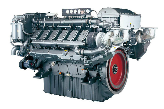
Yanmar Corporation from Japan gained fame on the whole planet as a manufacturer of diesel engines. At present, this company is rightfully considered the leader in terms of the
volume of not only the production of such products, but also sales.
Japanese corporation Yanmar also produces the final products. In this case, we are talking about Yanmar water pumps, boat engines, generators (power stations), garden tractors and other things
that are installed by the engines of our own production.
History of the company Yanmar began in 1912 in Japan. Only then the company was called Yamaoka Hatsudoki Kosakusho (Yamaoka Hatsudoki Kosakuse). Brand Yanmar appeared only nine years after the
company was founded. In the year 1921.
The name of the company Yanmar is easy to explain. It comes from the word oni-yanma, which in translation means «dragonfly wings». The fact is that for Japanese the dragonfly is considered a
symbol of a rich harvest. So, in this case, the brand was supposed to personify the image of the company, which is ready to dynamically develop. The angular form of the logo is evidence that the
company is determined to meet the future, which is marked by leadership and technological progress. Corporate red color is a symbol of innovative spirit.
In 1933, the engineers of the Japanese company Yamaoka Hatsudoki Kosakusho successfully developed a diesel internal combustion engine, which was then very compact. The engine was not just a
prototype. It began to be released serially. Moreover, it very quickly found application in the manufacture of a variety of products.
Since the mid-1930s and for the next ten years, the company has opened several Yanmar diesel engine manufacturing enterprises throughout the island state. One plant — for example, in the city of
Nagahama. Another plant is in the city of Amagasaki.
In 1947, the company went on the road, which was supposed to work out a new direction of activity — the production of small diesel engines, which were intended for fishing vessels.
In 1952, the first common logo of the Yanmar Group appeared. It was based on the fact that the name of the company is written in Latin letters — YANMAR. The logo used now was developed in 1993.
It was necessary for this because many changes were made that were aimed at meeting modern requirements. Changes in production have underlined and changes in the logo.
Mini excavators YANMAR:
- YANMAR SV08-1
- YANMAR SV100
- YANMAR ViO15
- YANMAR ViO15-2
- YANMAR ViO15-2A
- YANMAR ViO20-2
- YANMAR ViO20-3
- YANMAR ViO27-2
- YANMAR ViO27-3
- YANMAR ViO35-2
- YANMAR ViO75A
- YANMAR ViO35-3
- YANMAR ViO40-2A
- YANMAR ViO45-5
- YANMAR ViO50-2A
- YANMAR ViO55-5
- YANMAR ViO70
- YANMAR ViO75A
- YANMAR B7-5A
- YANMAR CBL40
- YANMAR IN 08-3
- YANMAR В22-2В-Р
- YANMAR В22-2В-С
- YANMAR В27-2В-Р
- YANMAR В27-2В-С
- YANMAR В37-2В-Р
- YANMAR В37-2В-С
- YANMAR В502В-Р
- YANMAR В502В-С
Backhoe loaders YANMAR:
- YANMAR CBL40
- YANMAR C50R-3A
Loaders YANMAR:
- YANMAR V3-6
- YANMAR V4-6
Crawler mini dumpers YANMAR:
- YANMAR C12R-A
- YANMAR C30R
- YANMAR C50R-3A
-
Contents
-
Table of Contents
-
Troubleshooting
-
Bookmarks
Related Manuals for Yanmar 3TNV88F
Summary of Contents for Yanmar 3TNV88F
-
Page 1
SERVICE MANUAL INDUSTRIAL ENGINES 3TNV88F 0BTN4-G00400 PRINTED IN JAPAN… -
Page 2
TEL: +55-19-3801-9224 FAX: +55-19-3875-3899, 2241 http://www.yanmar.com.br tion storage and retrieval systems — without the written permission of YANMAR CO., LTD. SERVICE MANUAL 3TNV88F 1st edition: June 2012 1st edition 1st rev. : December 2012… -
Page 3: Table Of Contents
TABLE OF TNV DI Service Manual CONTENTS Page Introduction ………………1-1 YANMAR Warranties …………….2-1 Safety………………..3-1 General Service Information ………….. 4-1 Periodic Maintenance …………….. 5-1 Engine ………………..6-1 Fuel System ………………7-1 Cooling System ………………. 8-1 Lubrication System …………….9-1 Starter Motor………………
-
Page 4
TABLE OF CONTENTS This Page Intentionally Left Blank TNV DI Service Manual… -
Page 5
Refer to the documentation supplied by the optional equipment manufacturer for specific service instructions. YANMAR products are continuously undergoing improvement. This Service Manual might not address possible field modifications to the equipment. Contact an authorized YANMAR industrial engine dealer or distributor for answers to any questions relating to field modifications. -
Page 6
INTRODUCTION This Page Intentionally Left Blank 3TNV88F Service Manual… -
Page 7
What is Covered by this Warranty? ………. 2-3 How Long is the Warranty Period? ……….. 2-3 What the Engine Owner must Do: ……….2-3 To Locate an Authorized YANMAR Industrial Engine Dealer or Distributor: …………..2-4 What YANMAR will Do: …………. 2-4 What is not Covered by this Warranty? …….. -
Page 8: 3Tnv88F Service Manual
YANMAR WARRANTIES This Page Intentionally Left Blank 3TNV88F Service Manual…
-
Page 9: Yanmar Limited Warranty
YANMAR LIMITED WARRANTY What is Covered by this Warranty? YANMAR warrants to the original retail purchaser that a new YANMAR TNV series industrial engine will be free from defects in material and/or workmanship for the duration of the warranty period.
-
Page 10: To Locate An Authorized Yanmar Industrial Engine Dealer Or Distributor
• “Click” on the desired country or associate company to locate your nearest authorized YANMAR industrial engine dealer or distributor. • You may also contact YANMAR by clicking on “Inquiry” in the website heading and typing in your question or comment.
-
Page 11: Warranty Limitations
Failure to follow the requirements for submitting a claim under this warranty may result in a waiver of all claims for damages and other relief. In no event shall YANMAR or any authorized industrial engine dealer or distributor be liable for incidental, special or consequential damages. Such…
-
Page 12: Emission System Warranty
The California Air Resources Board (CARB), the Environmental Protection Agency (EPA) and YANMAR Co., Ltd. hereafter referred to as YANMAR, are pleased to explain the emission control system warranty on your industrial compression-ignition engine. In California, 2013 MY and subsequent model years off- road compression-ignition engines must be designed, built and equipped to meet the state’s stringent anti-…
-
Page 13: Warranty Coverage
Warranty Coverage: This warranty is transferable to each subsequent purchaser for the duration of the warranty period. Repair or replacement of any warranted part will be performed at an authorized YANMAR industrial engine dealer or distributor. Warranted parts not scheduled for replacement as required maintenance in the operation manual shall be warranted for the warranty period.
-
Page 14: Exclusions
You are responsible for initiating the warranty process. You must present your engine to a YANMAR dealer as soon as a problem exists. The warranty repairs should be completed by the dealer as expeditiously as possible.
-
Page 15: Safety
Section 3 3TNV88F Service Manual SAFETY Page Safety Statements …………….3-3 Safety Precautions …………….3-4 3TNV88F Service Manual…
-
Page 16
SAFETY This Page Intentionally Left Blank 3TNV88F Service Manual… -
Page 17: Periodic Maintenance
Safety Statements SAFETY SAFETY STATEMENTS DANGER YANMAR is concerned for your safety and your DANGER indicates a hazardous situation machine’s condition. Safety statements are one of which, if not avoided, will result in death or the primary ways to call your attention to the serious injury.
-
Page 18: Fuel System
• Failure to comply will result in death or source) well away when refueling. serious injury. • Never overfill the fuel tank. • Fill the fuel tank. Store any containers containing fuel in a well-ventilated area, away from any combustibles or sources of ignition. 3TNV88F Service Manual…
-
Page 19
• Failure to comply could result in death or until the fuel coming out of the air bleed port serious injury. is free of bubbles. • Failure to comply will result in death or serious injury. 3TNV88F Service Manual… -
Page 20
These surfaces are extremely hot while the engine is operating and could seriously burn you. • Failure to comply could result in death or serious injury. 3TNV88F Service Manual… -
Page 21
Always use a piece of wood or cardboard. and clothing away from moving/rotating parts. Have your authorized YANMAR industrial engine dealer or distributor repair the • Failure to comply could result in death or damage. -
Page 22
• Replacing the fuel injection pump involves containers of rewriting the fuel injection data in the E-ECU. hazardous substances Be sure to contact your local YANMAR dealer like parts cleaners, before replacing the fuel injection pump. primers, sealants and Failure to rewrite the fuel injection data before sealant removers. -
Page 23: Starter Motor
• Failure to comply may result in minor or NOTICE moderate injury. • Only use diesel fuels recommended by YANMAR CAUTION for the best engine performance, to prevent Flying Object Hazard! engine damage and to comply with EPA/ARB warranty requirements.
-
Page 24
• The standard range of ambient temperatures for time (less than three minutes) at an angle greater the normal operation of YANMAR engines is from than (IDI = 30°, DI = 35°) in any direction, engine oil +5 °F (-15 °C) to +113 °F (+45 °C). -
Page 25
SAFETY NOTICE NOTICE • Only use the engine oil specified. Other engine For maximum engine life, YANMAR recommends oils may affect warranty coverage, cause internal that when shutting the engine down, you allow the engine components to seize and/or shorten engine to idle, without load, for five minutes. -
Page 26: General Service Information
• Never attempt to modify the engine’s design or switch is in the ON position, see your authorized safety features such as defeating the engine YANMAR industrial engine dealer or distributor for speed limit control or the fuel injection quantity service before operating the engine.
-
Page 27
Do not replace individual components. NOTICE If the engine coolant pump must be replaced, replace the engine coolant pump as an assembly only. Do not attempt to repair the engine coolant pump or replace individual components. 3TNV88F Service Manual 3-13… -
Page 28: Electric Wiring
This will corrode the conductor and result O-ring dimensions are the same as a commercially in battery over-charging (boiling) and charging available O-ring, the material is different. malfunctions. Consult YANMAR before using the equipment in such an environment or the warranty NOTICE is voided.
-
Page 29
Any alterations to this engine may electrical equipment. void its warranty. Be sure to use YANMAR genuine replacement parts. NOTICE NOTICE Reversing the battery cable connections at the… -
Page 30
NOTICE • Tampering with or removing these devices may Always check the battery for proper charge. void the “YANMAR Limited Warranty.” Otherwise the electronically controlled engines may NOTICE fail to start. Never use a steel wire brush to clean fuel injectors. -
Page 31
E- techniques. ECU. • See your authorized YANMAR industrial engine • Take care to prevent water from entering the dealer or distributor for additional training. couplers when plugging or unplugging the connector. -
Page 32
SAFETY Safety Precautions This Page Intentionally Left Blank 3-18 3TNV88F Service Manual… -
Page 33: Cooling System
Section 4 3TNV88F Service Manual GENERAL SERVICE INFORMATION Page Component Identification…………..4-3 Location of Labels …………….4-4 Engine Nameplate (Typical) …………4-4 Emission Control Regulations …………4-5 EPA/ARB Regulations — USA Only ……….4-5 Emission Control Labels…………..4-5 EPA/CARB Labels (Typical) …………4-5 Engine Family………………
-
Page 34
Description of Model Number……….. 4-22 Engine General Specifications ……….4-22 Principal Engine Specifications …………4-23 Engine Service Standards………….. 4-24 Tightening Torques for Standard Bolts and Nuts ……4-25 Abbreviations and Symbols…………4-27 Symbols………………4-27 Unit Conversions …………….4-28 3TNV88F Service Manual… -
Page 35: 3Tnv88F Service Manual
9 – Fuel injection pump 20 – Starter motor 10 – Engine oil filter 21 – Exhaust manifold 11 – Intake manifold 22 – Alternator Figure 4-1 *: Engine oil drain plug location may vary based on oil pan options. 3TNV88F Service Manual…
-
Page 36: Location Of Labels
GENERAL SERVICE INFORMATION Location of Labels LOCATION OF LABELS Figure 4-2 shows the location of regulatory and safety labels on YANMAR TNV series direct injection model engine. 045044-00X01 Figure 4-2 ■ Location of labels/nameplates on direct injection model engines Model…
-
Page 37: Emission Control Regulations
EPA/ARB Regulations — USA Only regulations a particular engine complies with. We have listed several different types of labels you YANMAR TNV engines meet Environmental might find on your engine. Protection Agency (EPA) (U. S. Federal) emission control standards as well as the California Air EPA/CARB Labels (Typical) Resources Board (ARB, California) regulations.
-
Page 38: Engine Family
The following is an explanation of the Engine Family designation: C YDX L 1.64 M Method of air aspiration Number of cylinders Engine speed specifications Displacement (l) Non-road/off-road engine YANMAR diesel Model year C: 2012 D: 2013 E: 2014 F: 2015 3TNV88F Service Manual…
-
Page 39: Function Of Major Engine Components
Since the air cleaner is application specific, it must be carefully selected by an application engineer. It is not part of the basic engine package as shipped from the YANMAR factory. Periodic replacement of the air cleaner filter element is necessary. See the Periodic Maintenance Schedule on page 5-5 for the replacement frequency.
-
Page 40: Main Electronic Control Components And Features
15 seconds. The duration of energization depends on the engine coolant temperature. The HEAT indicator is on during energization. When the indicator goes out, turn the key switch to the START position to start the engine. 3TNV88F Service Manual…
-
Page 41
Brings the running engine in low idle mode automatically when the accelerator pedal is not operated for a predetermined period of time. When the pedal is operated, i.e., the accelerator sensor is activated, the low idle mode is cancelled. 3TNV88F Service Manual… -
Page 42: Function Of Cooling System Components
The application specific items are not part of the basic engine package as shipped from the YANMAR factory. • Engine cooling fan The engine cooling fan is driven by a V-belt which is powered by the crankshaft V-pulley.
-
Page 43: Diesel Fuel
• The sulfur content must not exceed 0.5 % by Diesel fuel should comply with the following volume. Less than 0.05 % is preferred. specifications. The table lists several worldwide For electronically controlled engines 3TNV88F specifications for diesel fuels. (EGR system equipped engine), it is mandatory Diesel fuel specification Location to use fuel that does not contain 0.1 % or more…
-
Page 44
% bio- diesel and 93 % conventional petroleum- Approved engines based diesel fuel) and “B 20” (a blend of 20 % All of the following engine series of YANMAR can biodiesel and 80 % conventional diesel). Raw be operated with biodiesel with concentrations up pressed vegetable oils are not considered to be to B 20. -
Page 45
3 months of the date (B 8 through B 20) of biodiesel manufacture. Therefore biodiesel When operating your applicable YANMAR engine needs to be used at latest within 2 months from with biodiesel blends concentrated above B 5, we… -
Page 46
(Because of cartridge type) Need to change only O-ring. : 24326-000750 —> C Water separator : 24316-000160 —> D : 24316-000070 —> E : 24326-000650 —> C (Need only for TAIYO-GIKEN) 24326-000750 (G75) 24316-000160 (P16) 24316-000070 (P7) 033042-00X 4-14 3TNV88F Service Manual… -
Page 47: Filling The Fuel Tank
GENERAL SERVICE INFORMATION Filling The Fuel Tank NOTICE DANGER • Only use diesel fuels recommended by YANMAR for the best engine performance, to prevent Fire and Explosion Hazard! engine damage and to comply with EPA/ARB • Diesel fuel is flammable and warranty requirements.
-
Page 48: Priming The Fuel System
2. Never use the starter motor to crank the engine in order to prime the fuel system. This may cause the starter motor to overheat and damage the coils, pinion and/or ring gear. 4-16 3TNV88F Service Manual…
-
Page 49: Engine Oil
(Figure 4-5). • Never mix different types of engine oil. This may • YANMAR does not recommend the use of engine adversely affect the lubricating properties of the oil “additives”. engine oil.
-
Page 50: Checking Engine Oil
Refer to the operation manual provided by the driven machine manufacturer for the actual engine oil capacity of your machine. The following are the engine oil capacities for various YANMAR TNV engines. Dipstick Engine model upper limit/lower limit 7.1/4.1 qt (6.7/3.9 l)
-
Page 51: Engine Coolant
If contact with the eyes or skin should occur, flush eyes and wash immediately with clean water. • Failure to comply may result in minor or moderate injury. 3TNV88F Service Manual 4-19…
-
Page 52: Engine Coolant Specifications
(Figure 4-8, (1)) in the • Water quality is important to coolant cylinder block is closed. performance. YANMAR recommends that soft, distilled, or demineralized water be used to mix with coolants. • Never mix extended or long life coolants and conventional (green) coolants.
-
Page 53: Engine Coolant Capacity (Typical)
Align the tabs on the back side of the radiator capacity on your machine. cap with the notches on the engine coolant filler The engine coolant capacity of 3TNV88F is port. Press down and turn the cap clockwise 3TNV88F 2.1 qt (2.0 l) (engine only).
-
Page 54: Specifications
• Fuel feeding pressure: 20 ± 10 kPa (net) after engine break-in has been performed with the cooling fan, air cleaner and muffler installed to the engine. • With cooling fan, air cleaner, muffler: YANMAR standard • After the engine break-in period. Output allowable deviation: ± 3 % •…
-
Page 55: Principal Engine Specifications
588 × 577 × 634 mm 6.7/3.9 l Engine oil pan capacity Dipstick upper limit/lower Limit 2.0 l (Engine only) Engine coolant capacity Standard cooling fan ø335 Pusher Crank V-pulley dia./Fan V-pulley dia. ø110/ø110 mm Top clearance 0.73 ± 0.06 mm 3TNV88F Service Manual 4-23…
-
Page 56: Engine Service Standards
176 °F — 183 °F Thermostat Option or above (80 °C — 84 °C) 203 °F (95 °C) 225 °F — 235 °F See Temperature switch Coolant temperature switch – (107 °C — 113 °C) on page 8-8 4-24 3TNV88F Service Manual…
-
Page 57: Tightening Torques For Standard Bolts And Nuts
(215.7- 235.4 N·m, 22 — 24 kgf·m) 7 ft-lb (87 in.-lb, 9.8 N·m, 1.0 kgf·m) 14 ft-lb (173 in.-lb, 19.6 N·m, 2.0 kgf·m) PT plug – 22 ft-lb (29.4 N·m, 3.0 kgf·m) 43 ft-lb (58.8 N·m, 6.0 kgf·m) 3TNV88F Service Manual 4-25…
-
Page 58
29 — 36 ft-lb (39.2 — 49.0 N·m, 4.0 — 5.0 kgf·m) 36 — 43 ft-lb (49.0 — 58.8 N·m, 5.0 — 6.0 kgf·m) Note: Torque values shown in this manual are for clean, non-lubricated fasteners unless otherwise specified. 4-26 3TNV88F Service Manual… -
Page 59: Abbreviations And Symbols
■ Symbols I.D. inside diameter identification ° degree indirect injection plus inch in.Aq inches Aqueous (water) minus in.Hg inches Mercury ± plus or minus in.-lb inch pound joule micro Japanese Automobile Standards percent JASO Organization 3TNV88F Service Manual 4-27…
-
Page 60: Unit Conversions
× 0.4536 = kgf ■ Units of temperature × 0.2248 = lbf × 0.1020 = kgf °F = (1.8 × °C) + 32 × 2.2050 = lbf °C = 0.556 × (°F — 32) × 9.8070 4-28 3TNV88F Service Manual…
-
Page 61
Section 5 3TNV88F Service Manual PERIODIC MAINTENANCE Page Before You Begin Servicing …………5-3 Introduction………………5-4 The Importance of Periodic Maintenance……..5-4 Performing Periodic Maintenance ……….5-4 YANMAR Replacement Parts………… 5-4 Required EPA/ARB Maintenance — USA Only……5-4 EPA/ARB Installation Requirements — USA Only …… 5-4 Periodic Maintenance Schedule………… -
Page 62
PERIODIC MAINTENANCE This Page Intentionally Left Blank 3TNV88F Service Manual… -
Page 63: Before You Begin Servicing
Before You Begin Servicing PERIODIC MAINTENANCE BEFORE YOU BEGIN SERVICING Before performing any service procedures within this section, read the following safety information and review the Safety section on page 3-1. 3TNV88F Service Manual…
-
Page 64: Introduction
PERIODIC MAINTENANCE Introduction INTRODUCTION YANMAR Replacement Parts YANMAR recommends that you use genuine This section of the Service Manual describes the YANMAR parts when replacement parts are procedures for proper care and maintenance of the needed. Genuine replacement parts help ensure engine.
-
Page 65: Periodic Maintenance Schedule
See YANMAR Limited Warranty in Warranty Section. Consult your authorized YANMAR dealer or distributor for assistance when checking items marked with a : Check : Replace : Contact your authorized YANMAR industrial engine dealer or distributor…
-
Page 66
PERIODIC MAINTENANCE Periodic Maintenance Schedule : Check : Replace : Contact your authorized YANMAR industrial engine dealer or distributor Periodic maintenance interval Every Every Every Every Every Every Every System Check item Daily 1000 1500 2000 3000 hours hours hours… -
Page 67: Periodic Maintenance Procedures
• Failure to comply could result in death or serious injury. • Failure to follow these procedures may seriously harm the environment. 3TNV88F Service Manual…
-
Page 68
2.0 — 2.4 kgf·m) or one additional turn using the filter wrench. Engine oil filter Part No. Standard Dust proof* 129150-35153 119005-35151 * Consult the operation manual for the driven machine for applicability of the dust proof filter. 046796-00X00 Figure 5-1 3TNV88F Service Manual… -
Page 69
(10 — 14 mm) (7 — 10 mm) (9 — 13 mm) Note: A “Used V-Belt” refers to a V-belt which has been used on a running engine for five minutes or more. K0000063B 045046-00X02 Figure 5-4 Figure 5-3 3TNV88F Service Manual… -
Page 70
5. Install the new V-belt. Refer to the table for proper tension. New V-belt tension 5/16 — 7/16 in. 3/16 — 5/16 in. 1/4 — 7/16 in. (8 — 12 mm) (5 — 8 mm) (7 — 11 mm) 5-10 3TNV88F Service Manual… -
Page 71: Every 50 Hours Of Operation
If this happens, turn the air vent screw on the top of the fuel filter/water separator 2 — 3 turns counterclockwise. Be sure to tighten the air vent screw after the water has drained out. 3TNV88F Service Manual 5-11…
-
Page 72
5. Open the fuel cock (Figure 5-7, (3)). 6. Be sure to prime the diesel fuel system when you are finished. See Priming the Fuel System on page 4-16. 7. Check for leaks. 5-12 3TNV88F Service Manual… -
Page 73
Periodic Maintenance Procedures PERIODIC MAINTENANCE • If the engine still will not start after charging, have NOTICE your authorized YANMAR industrial engine dealer or distributor check the battery and the engine’s • Always be environmentally starting system. responsible. • If operating the machine where the ambient temperature could drop to 5 °F (-15 °C) or less,… -
Page 74: Every 250 Hours Of Operation
K0000065A Figure 5-9 4. Drain the tank until clean diesel fuel with no water and dirt flows out. Reinstall and tighten the drain plug firmly. 5. Reinstall the fuel cap. 6. Check for leaks. 5-14 3TNV88F Service Manual…
-
Page 75
50 hours. Replace the engine oil filter at the same time. See Replace engine oil and engine oil filter on page 5-7. F U L L O W K0000085A Figure 5-10 3TNV88F Service Manual 5-15… -
Page 76
42 — 71 PSI (0.29 — material to enter the engine and damage it. 0.49 MPa; 3.0 — 5.0 kgf/cm ) compressed air to remove the particulates. Use the lowest possible air pressure to remove the dust without damaging the element. 5-16 3TNV88F Service Manual… -
Page 77: Every 500 Hours Of Operation
• Never dispose of hazardous materials irresponsibly by dumping them into a sewer, on the ground, or into ground water or waterways. • Failure to follow these procedures may seriously harm the environment. 3TNV88F Service Manual 5-17…
-
Page 78
Periodic Maintenance Procedures NOTICE Applicable fuel filter Part No. Standard Dust proof* For maximum engine life, YANMAR recommends 119802-55801 129907-55801 that when shutting the engine down, you allow the engine to idle, without load, for five minutes. This * Consult the operation manual for the driven will allow the engine components that operate at machine for applicability of the dust proof filter. -
Page 79
15. Check for leaks. 045100-00X00 Figure 5-14 2. Close (Figure 5-14, (2)) the fuel cock (Figure 5-14, (3)). 3. Loosen the drain cock (Figure 5-14, (4)) and drain the contaminants. See Drain fuel filter/water separator on page 5-11. 3TNV88F Service Manual 5-19… -
Page 80: Every 1000 Hours Of Operation
Drain, flush and refill the cooling serious injury. system with new coolant every 1000 hours or once a year, whichever comes first. 1. Allow engine and coolant to cool. 2. Remove the radiator cap (Figure 5-15, (1)). 5-20 3TNV88F Service Manual…
-
Page 81
5. After draining the engine coolant, flush the radiator and engine block to remove any rust, scale and contaminants. Then reinstall and tighten the drain plug or close the drain cock in the radiator. Reinstall and tighten the cylinder block drain plug. 3TNV88F Service Manual 5-21… -
Page 82: Every 1500 Hours Of Operation
Figure 5-17 This procedure is considered normal maintenance and is performed at the owner’s expense. This 2. Remove the diaphragm cover, spring, procedure is not covered by the YANMAR Limited diaphragm plate (Figure 5-17, (5)) and Warranty. diaphragm. 3. Inspect the diaphragm for tears. Inspect the spring for distortion.
-
Page 83: Every 2000 Hours Of Operation
Replace the hoses at least every two years. ■ Lap the intake and exhaust valves Adjustment is necessary to maintain proper contact of the valves and seats. See Inspection of intake and exhaust valves on page 6-23. 3TNV88F Service Manual 5-23…
-
Page 84: Every 3000 Hours Of Operation
3000 hours. Consult your local YANMAR dealer for this service. ■ Inspect and clean EGR lead valve The EGR lead valve is located in the passage of recirculated gas.
-
Page 85
Section 6 3TNV88F Service Manual ENGINE Page Before You Begin Servicing …………6-3 Introduction………………6-4 Cylinder Head Specifications …………6-4 Adjustment Specifications …………6-4 Cylinder Head…………….6-4 Intake/Exhaust Valve and Guide ……….6-4 Push Rod………………. 6-5 Rocker Arm and Shaft …………… 6-5 Valve Spring ……………. -
Page 86
Honing and Boring…………..6-46 Reassembly of Crankshaft and Piston Components….6-47 Reassembly of Camshaft and Timing Components ….6-53 Final Reassembly of Engine…………. 6-56 EGR system ………………. 6-57 EGR System…………….6-57 Inspecting/Cleaning EGR Related Components …… 6-60 3TNV88F Service Manual… -
Page 87: Before You Begin Servicing
Before You Begin Servicing ENGINE BEFORE YOU BEGIN SERVICING Before performing any service procedures within this section, read the following safety information and review the Safety section on page 3-1. 3TNV88F Service Manual…
-
Page 88: Introduction
(14.71 — 15.00 mm) guides on page 6-26. Valve guide installation method Cold-fitted – See Reassembly of intake 0.736 — 0.748 in. Valve stem seal projection from cylinder head – and exhaust valves on (18.7 — 19.0 mm) page 6-26. 3TNV88F Service Manual…
-
Page 89: Push Rod
(0.016 — 0.054 mm) (0.13 mm) Valve Spring Inspection item Standard Limit Reference page 1.6535 in. 1.6339 in. Free length (42.0 mm) (41.5 mm) See Inspection of valve springs on page 6-25. 0.0551 in. Squareness – (1.4 mm) 3TNV88F Service Manual…
-
Page 90: Camshaft And Timing Gear Train Specifications
Standard Limit Reference page Crank gear, cam gear, idler gear, fuel injection 0.0028 — 0.0059 in. 0.0067 in. See Checking timing gear pump gear and PTO gear (0.07 — 0.15 mm) (0.17 mm) backlash on page 6-34. 3TNV88F Service Manual…
-
Page 91: Crankshaft And Piston Specifications
1.0234 — 1.0236 in. 1.0222 in. Piston pin Pin outside diameter piston rings and wrist pin (25.995 — 26.000 mm) (25.965 mm) on page 6-41. 0.0000 — 0.0006 in. 0.0029 in. Oil clearance (0.000 — 0.014 mm) (0.074 mm) 3TNV88F Service Manual…
-
Page 92: Piston Ring
■ Connecting rod big end Inspection item Standard Limit Reference page See Inspection of 0.0079 — 0.0157 in. Side clearance – connecting rod on (0.20 — 0.40 mm) page 6-43. Note: See Special Torque Chart on page 6-10 for other specifications. 3TNV88F Service Manual…
-
Page 93: Tappet
3.4646 — 3.4657 in. 3.4724 in. Cylinder inside diameter (88.000 — 88.030 mm) (88.200 mm) See Inspection of cylinder Roundness block on page 6-41. 0.0004 in. (0.01 mm) 0.0012 in. Cylinder bore or less (0.03 mm) Taper 3TNV88F Service Manual…
-
Page 94: Special Torque Chart
1.53 — 2.04 kgf·m) 9 — 13 in·lb Glow connector nut M4 × 0.7 mm Not applied (1 — 1.5 N·m) Note: See Tightening Torques for Standard Bolts and Nuts on page 4-25 for standard hardware torque values. 6-10 3TNV88F Service Manual…
-
Page 95: Special Service Tools
Valve guide tool 3TNV88F (15 mm) (65 mm) (14 mm) (20 mm) (for installing valve guide) Locally manufactured 001421-00X Fuel injector YANMAR Part No. 129470-92305 removal tool K0001618 Connecting rod Model bushing 0.787 in. 3.937 in. 1.024 in. 1.142 in. 3TNV88F…
-
Page 96
129400-92430 (83 — 95 mm) (for preparation of cylinder walls) 010930-00X Piston ring YANMAR Part No. 95550-002476 compressor The piston insertion tool is applicable for (for installing 2.362 — 4.921 in. (60 — 125 mm) diameter pistons piston) 007236-00X Piston ring… -
Page 97: Measuring Instruments
001433-00X For measuring outside diameters, depth, Calipers Locally available thickness and width 001434-00X Depth micrometer Locally available For measuring of valve recession 001435-00X For measuring valve spring inclination and Square Locally available straightness of parts 001436-00X 3TNV88F Service Manual 6-13…
-
Page 98
For measuring shaft bend 001437-00X For tightening nuts and bolts to the specified Torque wrench Locally available torque 001438-00X For measuring piston ring gaps, piston ring Feeler gauge Locally available clearance, and valve adjustment clearance 001426-00X 6-14 3TNV88F Service Manual… -
Page 99: Cylinder Head
Cylinder Head ENGINE CYLINDER HEAD Cylinder Head Components 046614-00X00 Figure 6-1 3TNV88F Service Manual 6-15…
-
Page 100: Components Of A Cylinder Head
27 – Fuel injector retainer 28 – Washer 29 – Fuel injector retainer bolt 30 – Fuel injector nozzle protector 31 – Fuel injector nozzle seat 32 – Push rod 33 – Crankcase breather components 34 – Valve cover 6-16 3TNV88F Service Manual…
-
Page 101: Disassembly Of Cylinder Head
See Removal of Fuel Injectors on page 7-25. 046797-00X00 Figure 6-3 2. Remove the intake manifold bolts (Figure 6-4, (1)). Remove the intake manifold (Figure 6-4, (2)). Discard the intake manifold gasket (Figure 6-4, (3)). 3TNV88F Service Manual 6-17…
-
Page 102
(Figure 6-6, (4)). Failure to remove the glow plugs in advance could result in damages to the glow plugs because their tips are protruding from the cylinder head combustion chamber surface. 6-18 3TNV88F Service Manual… -
Page 103
2. Slide the rocker arm shaft (Figure 6-8, (3)) out of the rocker arm supports (Figure 6-8, (5)), springs (Figure 6-8, (1)), and rocker arms (Figure 6-8, (2)). Note: Mark the rocker arms so they can be reinstalled with the original matching valve and pushrod. 3TNV88F Service Manual 6-19… -
Page 104
5. Slowly release the tension on the valve spring. 6. Remove the spring retainer (Figure 6-12, (3)) and valve spring (Figure 6-12, (4)). 046618-00X00 Figure 6-10 046621-00X00 Figure 6-12 7. Repeat the procedure with all remaining valves. 6-20 3TNV88F Service Manual… -
Page 105: Cleaning Of Cylinder Head Components
Any part determined to not meet the service standard or limit before the next service, as determined from the state of current rate of wear, should be replaced even though the part currently meets the service standard limit. 3TNV88F Service Manual 6-21…
-
Page 106
K0001952 (Figure 6-15) are within the specified limits. See Rocker Arm and Shaft on page 6-5 for the Figure 6-16 service limit. 2. Inspect the contact areas (Figure 6-15, (1)) for excessive wear or damage. 6-22 3TNV88F Service Manual… -
Page 107
Figure 6-20 K0000192 Figure 6-18 If distortion exceeds the service limit, resurface or replace the cylinder head. Remove only enough material to make the cylinder head flat, but do not remove more than 0.008 in. (0.20 mm). 3TNV88F Service Manual 6-23… -
Page 108
(Figure 6-23, (1)) and even in width. K0001755 Figure 6-22 K0001691B Figure 6-23 Also visually inspect the valve seat for even contact. Light cutting can be performed by the use of a hand-operated cutter (Figure 6-24, (3)). 6-24 3TNV88F Service Manual… -
Page 109
Fractures Check for fractures on the inside and outside portions of the springs. If the valve spring is fractured, replace the valve spring. Corrosion Check for corrosion of the spring material caused by oxidation. 3TNV88F Service Manual 6-25… -
Page 110: Reassembly Of Cylinder Head
(Figure 6-30, (2)) between guide installation tool (Figure 6-28, (2)). See the guide and the seal. See Valve Stem Seal Valve Guide Projection specification starting on Projection specification on page 6-5. page 6-4. K0001756A Figure 6-28 6-26 3TNV88F Service Manual…
-
Page 111
Fan End 7. Insert the valve keepers (Figure 6-31, (2)) and slowly release the tension on the valve spring. K0001875X01 Install the valve cap (Figure 6-31, (1)). Repeat Figure 6-33 the steps on all the remaining valves. 3TNV88F Service Manual 6-27… -
Page 112
7. Adjust the valve clearance. See Measuring and hole for the shaft alignment stud Adjusting Valve Clearance on page 6-30. (Figure 6-35, (4)). Align the hole in the rocker arm shaft and the hole in the rocker arm support. Reinstall the alignment stud. 6-28 3TNV88F Service Manual… -
Page 113
10. Reinstall the coolant hoses on the cold start Figure 6-36 device on the fuel injection pump. 5. Reinstall the intake manifold using a new 11. Reinstall the alternator. See Installation of gasket. Tighten the bolts to the specified Alternator on page 11-14. torque. 3TNV88F Service Manual 6-29… -
Page 114: Measuring And Adjusting Valve Clearance
No. 1 piston is at TDC on the exhaust stroke (exhaust valve only open). ■ 3-cylinder engines Cylinder No. Valve Intake Exhaust Intake Exhaust Intake Exhaust No. 1 cylinder at TDC compression No. 1 cylinder at TDC exhaust 6-30 3TNV88F Service Manual…
-
Page 115
7. Apply oil to the contact surface between the adjusting screw and push rod. 8. Rotate the crankshaft. Measure and adjust the valves on the next cylinder. Continue until all the valves have been measured and adjusted. 3TNV88F Service Manual 6-31… -
Page 116: Crankshaft And Camshaft Components
ENGINE Crankshaft and Camshaft Components CRANKSHAFT AND CAMSHAFT COMPONENTS 046622-00X00 Figure 6-41 6-32 3TNV88F Service Manual…
-
Page 117: Disassembly Of Engine
7. Drain the engine oil into a suitable container. Remove the oil filter. 8. Remove the cylinder head. See Cylinder Head on page 6-15. 3TNV88F Service Manual 6-33…
-
Page 118: Disassembly Of Camshaft And Timing Components
4. Remove the gear case cover (Figure 6-42, (1)). K0002086 Figure 6-44 K0001641A 2. Rotate the idler gear back and forth to check Figure 6-42 the idler gear-to-crankshaft gear backlash. The total indicator reading is the backlash. Record the measurement. 6-34 3TNV88F Service Manual…
-
Page 119
3. Removal of the camshaft gear requires the camshaft be removed and placed in a press. Do not remove the camshaft gear unless it or the camshaft is damaged and requires replacement. See Removal of camshaft on page 6-36. 046358-00X00 Figure 6-47 3TNV88F Service Manual 6-35… -
Page 120
Use a knife-edge puller and a press to remove the gear. The gear is a K0001710B shrink-fit and will need to be heated to 356 — Figure 6-49 392 °F (180 — 200 °C) to remove. 6-36 3TNV88F Service Manual… -
Page 121: Disassembly Of Crankshaft And Piston Components
(Figure 6-52). See Connecting Rod on page 6-8 for the standard limit. If the measurement is out of specification, replace the crankshaft, connecting rod, or both. K0002016 Figure 6-51 K0000219 Figure 6-52 3TNV88F Service Manual 6-37…
-
Page 122
6- Compare the width of the flattened PLASTIGAGE to the graduation marks on the package (Figure 6-54, (1)). The mark that most closely matches the width of the flattened PLASTIGAGE will indicate the bearing oil clearance. K0001960 Figure 6-55 6-38 3TNV88F Service Manual… -
Page 123
• Method A: Install a dial gauge (Figure 6-57, (1)) on the cylinder block. Move the crankshaft (Figure 6-57, (2)) in and out to measure the end play. Record the measurement. 046359-00X00 Figure 6-59 K0001961 Figure 6-57 3TNV88F Service Manual 6-39… -
Page 124: Inspection Of Crankshaft And Camshaft Components
Thoroughly clean all components using a brush and appropriate solvent. Each part must be free of carbon, gasket material, metal filings and other debris. K0001899 Figure 6-61 6. Remove the crankshaft from the engine. 6-40 3TNV88F Service Manual…
-
Page 125
The 2. Apply a continuous bead of ThreeBond Liquid same procedure is done for both connecting rods Gasket No. 1207F, YANMAR Part No. 977770- and main bearings. 1207F to the outside diameter of a new oil seal (Figure 6-63, (2)), and install in the gear case ■… -
Page 126
(Figure 6-69). Use a feeler gauge to measure the clearance between the piston ring and the piston ring land. Record the measurements. See Piston Ring on page 6-8 for specifications. Replace the piston if not within specification. 6-42 3TNV88F Service Manual… -
Page 127
2. Place the connecting rod bearing inserts into the connecting rod and connecting rod cap. Install the rod cap and tighten the bolts to the specified torque. 3. Measure the inside diameter. See Crankshaft on page 6-7 for specifications. K0001964 Figure 6-70 3TNV88F Service Manual 6-43… -
Page 128
3. Measure the tappet bores in the cylinder block. for specifications. Take measurements at See Tappet on page 6-9 for the service limit. several places around each bearing surface. If not within specification, grind the journals and install undersize bearings, or replace the crankshaft. 6-44 3TNV88F Service Manual… -
Page 129
K0001712A Figure 6-77 4. Measure the diameter of the gear end (Figure 6-78, (1)), intermediate (Figure 6-78, (2)), and flywheel end (Figure 6-78, (3)) bearing journals. See Camshaft on page 6-6 for specifications. K0001713A Figure 6-78 3TNV88F Service Manual 6-45… -
Page 130: Honing And Boring
(Figure 6-80, (1)), move the rotating hone up and down in the cylinder bore to accomplish a 30° to 40° crosshatch pattern (Figure 6-80). This will provide the ideal surface for the proper seating of new piston rings. 6-46 3TNV88F Service Manual…
-
Page 131: Reassembly Of Crankshaft And Piston Components
(Figure 6-82, (7)) using a press and the appropriate service tool. Be sure to align the oil K0000249B holes. Figure 6-81 NOTICE Solvents will not adequately remove honing residue, resulting in premature piston and ring wear. Always wash cylinders using hot, soapy water. 3TNV88F Service Manual 6-47…
-
Page 132
Figure 6-83 stamped on the connecting rod. Note: The actual appearance of the match marks on the piston and connecting rod may vary, but they will always be in the same locations. 6-48 3TNV88F Service Manual… -
Page 133
5. Reinstall the second circlip (Figure 6-85, (4)) Figure 6-86 and ensure it is securely seated in the groove. NOTICE Always use a piston ring installation tool (expander) when installing piston rings. Never attempt to install piston rings by hand. 3TNV88F Service Manual 6-49… -
Page 134
The main bearing caps are numbered and have the wrist pin. arrows for proper positioning. The No. 1 cap is at the flywheel end. The arrows point toward the flywheel end of the engine. 4. Reinstall the main bearing caps (Figure 6-89, (3)). 6-50 3TNV88F Service Manual… -
Page 135
Figure 6-89 6. Rotate the crankshaft to assure it turns freely. 7. Apply ThreeBond Liquid Gasket No. 1207F, YANMAR Part No. 977770-1207F to the mounting flange of the seal housing (Figure 6-90, (2)). 8. Align the seal housing with the two dowel pins. -
Page 136
1 – Fuel injection pump side of engine respective cylinders. 2 – Piston identification mark 3 – Embossed mark on connecting rod 4 – Rod and cap match marks 5 – Flywheel end of engine 6 – Camshaft side of engine Figure 6-92 6-52 3TNV88F Service Manual… -
Page 137: Reassembly Of Camshaft And Timing Components
(Figure 6-96, (4)) onto the camshaft using a 2. Apply a continuous bead of ThreeBond Liquid press. Gasket No. 1207F, YANMAR Part No. 977770- 1207F to the mounting area of the gear case or Note: Heat the gear to 356 — 392 °F (180 — 200 front plate.
-
Page 138
(Figure 6-97, (C)) is approximately at the 1. Apply a continuous bead of ThreeBond Liquid 9 o’clock position. Gasket No. 1207F, YANMAR Part No. 977770- 1207F to the mounting area of the gear case cover (Figure 6-99, (1)). Be sure to circle the bolt holes. -
Page 139
K0002133 2. Apply a continuous bead of ThreeBond Liquid Figure 6-100 Gasket No. 1207F, YANMAR Part No. 4. Reinstall the washer and bolt. Tighten the bolt 977770-1207F to the mounting surface of the to the specified torque. See Special Torque oil pan (Figure 6-102, (1)). -
Page 140: Final Reassembly Of Engine
4. Reconnect the fuel and coolant lines. 5. Reinstall the alternator. 6. Reconnect and adjust the throttle cable. 7. Reconnect all electrical connections. 8. Fill the engine with oil and coolant. 9. Reconnect the battery cables, negative (-) cable last. 6-56 3TNV88F Service Manual…
-
Page 141: Egr System
EGR System 046361-00X00 1 – EGR pipe 4 – Cooling water hose, EGR valve outlet 2 – Exhaust manifold 5 – Intake manifold 3 – Cooling water hose, EGR valve inlet 6 – EGR valve Figure 6-103 3TNV88F Service Manual 6-57…
-
Page 142
• Failure to comply could result in death or serious injury. • Failure to comply could result in death or serious injury. 6-58 3TNV88F Service Manual… -
Page 143
The EGR system uses steel gaskets at the joints between its components/parts. These steel gaskets are specific to the respective joints. When you remove the system’s components/parts and reinstall them, replace the steel gaskets between them with new correct ones. 3TNV88F Service Manual 6-59… -
Page 144: Inspecting/Cleaning Egr Related Components
15 ± 2 at 20 °C — — Note: The higher the temperature, the higher the coil resistance. Therefore, wait for the EGR valve to return to normal state before measuring the resistances. 6-60 3TNV88F Service Manual…
-
Page 145
Assemble without When cleaning the valves, take extreme care to misalignment. prevent water, solvent, cleaner, and other liquid Valve plate from entering into the motor and coupler terminals; otherwise, failure may result. Figure 6-107 3TNV88F Service Manual 6-61… -
Page 146
The EGR system uses steel gaskets at the joints between its components/parts. When you remove the system’s components/parts and reinstall them, replace the steel gaskets between them with new correct ones. 6-62 3TNV88F Service Manual… -
Page 147
Section 7 3TNV88F Service Manual FUEL SYSTEM Page Before You Begin Servicing …………7-3 Trochoid Fuel Pump …………..7-4 Electronically Controlled Governor ……….7-4 Fuel System Specifications …………. 7-5 Special Torque Chart…………..7-5 Special Service Tools…………..7-7 Measuring Instruments…………..7-7 Fuel System Diagram………….. -
Page 148
FUEL SYSTEM This Page Intentionally Left Blank 3TNV88F Service Manual… -
Page 149: Before You Begin Servicing
Before You Begin Servicing FUEL SYSTEM BEFORE YOU BEGIN SERVICING Before performing any service procedures within this section, read the following safety information and review the Safety section on page 3-1. 3TNV88F Service Manual…
-
Page 150: Trochoid Fuel Pump
• Because of this, the engine speed increases by approximately 75 min while the CSD is operating. When the water temperature becomes 10 °C or higher, the CSD is turned off and the engine returns to the normal speed. 3TNV88F Service Manual…
-
Page 151: Fuel System Specifications
30 — 33 ft·lb Fuel injector nozzle case nut (39.2 — 44.1 N·m; Not applied 4 — 4.5 kgf·m) 22 — 26 ft·lb Fuel injection pump plunger plug (30 — 35 N·m; Not applied 3.1 — 3.6 kgf·m) 3TNV88F Service Manual…
-
Page 152: Test And Adjustment Specifications
“V”, “W”, “R” or “S”. K0004105 Figure 7-2 Note: Fuel injector identification is critical as each engine has a unique fuel injection pressure. The fuel nozzle is specifically matched to the fuel injector by engine model and/or engine speed. 3TNV88F Service Manual…
-
Page 153: Special Service Tools
* These special service tools may also be available as an “MP Fuel Injection Pump Special Tool Set”, under a different part number, in territories serviced by YANMAR America and YANMAR Europe. Contact your authorized YANMAR dealer or distributor for details.
-
Page 154: Fuel System Diagram
8 – Pressure control valve 19 – Distributor shaft 9 – Trochoid pump 20 – Fuel return line 10 – Oil seal 21 – High-pressure fuel injection lines 11 – Fuel injection pump cam 22 – Fuel injector Figure 7-3 3TNV88F Service Manual…
-
Page 155: Fuel System Components
Fuel System Components FUEL SYSTEM FUEL SYSTEM COMPONENTS 046798-00X00 Figure 7-4 3TNV88F Service Manual…
-
Page 156
12 – Rear fuel injection pump support 13 – Fuel filter/water separator 14 – Electric fuel supply pump 15 – Fuel filter 16 – Fuel filter housing 17 – Stop solenoid 18 – Trochoid fuel pump Figure 7-5 7-10 3TNV88F Service Manual… -
Page 157: Fuel Injection Pump
“back up” wrench to prevent loosening of the delivery valves. 046799-00X00 6. First loosen the fuel line nuts at the fuel Figure 7-7 injectors and then at the fuel injection pump. 3TNV88F Service Manual 7-11…
-
Page 158
(Figure 7-9, (2)) from the pump. NOTICE Take care to not damage or bend the oil line. In some applications, it may be preferable to remove the complete oil line assembly from the engine before proceeding. 046373-00X00 Figure 7-10 7-12 3TNV88F Service Manual… -
Page 159
• On 3TNV88F engine the idler gear is not visible. Make a reference mark on the fuel injection pump drive gear (Figure 7-11, (1)) and a matching mark on the bore of the gear case opening (Figure 7-11, (2)). -
Page 160
Note: Some model engines may require the intake manifold and fuel injection pump insulator (Figure 7-16, (2)) be removed to access the inner fuel injection pump (Figure 7-16, (1)) retaining nuts. 046363-00X02 Figure 7-14 046372-00X00 Figure 7-16 7-14 3TNV88F Service Manual… -
Page 161: Installation Of Fuel Injection Pump
• Replacing the fuel injection pump involves rewriting the fuel injection data in the E-ECU. 22. Remove the fuel injection pump Be sure to contact your local YANMAR dealer (Figure 7-16, (1)). For purposes of future before replacing the fuel injection pump.
-
Page 162
Torque Chart on page 7-5. (A, B, C) on the fuel injection pump drive gear, idler gear, and crankshaft drive gear. Ensure all three timing marks (Figure 7-20, (A, B, C)) are aligned. 7-16 3TNV88F Service Manual… -
Page 163
K0000593A Figure 7-22 • Tighten the fuel injection pump retaining nuts to specification. See Special Torque Chart on K0002139 page 7-5. Figure 7-23 3TNV88F Service Manual 7-17… -
Page 164
(Figure 7-25, (3)) (rotated toward the engine) by the calculated negative amount. • Each mark on the timing sticker represents 0.5° timing change. K0002125A Figure 7-26 7-18 3TNV88F Service Manual… -
Page 165
Tighten the fuel injection pump mounting nuts to 8. Apply ThreeBond Liquid Gasket No. 1207F, specification. See Special Torque Chart on YANMAR Part No. 977770-1207F, or equivalent page 7-5. sealant to the sealing surface of the pump cover. Install the pump cover and tighten the 6. -
Page 166: Checking And Adjusting Fuel Injection Timing
16. Operate the engine and check for fuel and Figure 7-31 coolant leaks. K0002047 Figure 7-32 2. Using the FIR number for the engine being serviced use the Fuel Injection Reference (FIR) Chart under “FIE Specs” on the YANMAR Distributor Website (http://distributor.yanmar.co.jp). 7-20 3TNV88F Service Manual…
-
Page 167: Checking Fuel Injection Timing
4. Install a dial indicator adapter and clamp into the pump plunger opening. Note: Use the YANMAR Part No. 158090- 51831 M14 adapter for the MP2 fuel injection pumps and YANMAR Part No. 23000-013000 plunger adapter clamp (Figure 7-35, (1)).
-
Page 168
YANMAR Part No. (Figure 7-38, (1)). 158090-51870 or Mitutoyo No. 303613, into the adapter. Secure with the YANMAR Part No. Note: A typical flywheel will have multiple 23000-013000 plunger adapter clamp timing grids depending on the number of (Figure 7-35, (1)) at approximately the mid- cylinders. -
Page 169
Divide that measurement by the distance between the two “longer” marks. The resulting answer will tell you how many degrees there are between the TDC mark and the first “longer” mark. K0002065 Figure 7-39 3TNV88F Service Manual 7-23… -
Page 170: Adjusting Fuel Injection Timing
If the two marks are aligned, the fuel injection timing is correct. If the marks Figure 7-41 do not align, the fuel injection timing must be adjusted. See Adjusting Fuel Injection Timing on page 7-24. 7-24 3TNV88F Service Manual…
-
Page 171: Fuel Injectors
8. When the dial indicator reads 2.5 mm (0.098 046369-00X00 in.) of pump plunger lift and the target timing mark on the flywheel aligns with the reference Figure 7-43 mark on the flywheel housing or engine back plate, the injection timing is correct. 3TNV88F Service Manual 7-25…
-
Page 172
YANMAR Part No. 129470-92305, and a slide-hammer puller (Figure 7-45). -
Page 173: Testing Of Fuel Injectors
Use clean, filtered fuel or FIE calibration fluid for the test. 3. Using the correct adapter, connect a fuel injector to a nozzle tester. Aim the fuel injector into a suitable container to catch the fuel spray. 3TNV88F Service Manual 7-27…
-
Page 174: Disassembly And Inspection Of Fuel Injectors
(Figure 7-47). If a dripping or an 1. Clean carbon from used injectors using clean uneven pattern is seen (Figure 7-48), service diesel fuel. Hardened deposits or varnish can or replace the injector. be cleaned using a brass wire brush. 7-28 3TNV88F Service Manual…
-
Page 175
5. Turn the injector over and remove the nozzle K0001332A body, nozzle valve, valve stop spacer, nozzle spring seat, nozzle spring, and shims. Figure 7-51 8. Replace the fuel injector assembly if it fails any inspection. 3TNV88F Service Manual 7-29… -
Page 176: Adjusting Fuel Injector Pressure
8 – Nozzle valve 9 – Nozzle body 10 – Nozzle case nut Figure 7-52 The injection pressure will change by approximately 275 PSI (1.9 MPa; 19 kgf/cm ) for every 0.1 mm (0.004 in.) in shim thickness. 7-30 3TNV88F Service Manual…
-
Page 177: Installation Of The Fuel Injectors
“line” or “flare nut” wrench. 046647-00X00 Figure 7-53 7. Prime the fuel system. See Priming the Fuel System on page 4-16. 8. Operate the engine and check for fuel and coolant leaks. 3TNV88F Service Manual 7-31…
-
Page 178
FUEL SYSTEM Fuel Injectors This Page Intentionally Left Blank 7-32 3TNV88F Service Manual… -
Page 179
Section 8 3TNV88F Service Manual COOLING SYSTEM Page Before You Begin Servicing …………8-3 Introduction………………8-4 Cooling System Diagram…………..8-4 Engine Coolant Pump Components ……….8-5 Engine Coolant System Check…………8-6 Engine Coolant Pump …………..8-6 Removal of Engine Coolant Pump ……….8-6 Disassembly of Engine Coolant Pump …….. -
Page 180
COOLING SYSTEM This Page Intentionally Left Blank 3TNV88F Service Manual… -
Page 181: Before You Begin Servicing
Before You Begin Servicing COOLING SYSTEM BEFORE YOU BEGIN SERVICING Before performing any service procedures within this section, read the following safety information and review the Safety section on page 3-1. 3TNV88F Service Manual…
-
Page 182: Introduction
Introduction INTRODUCTION This section of the Service Manual describes the procedures necessary to service the 3TNV88F engine coolant pump. This engine coolant pump is representative of the coolant pumps used on other TNV model engines. For specific part detail, see the parts catalog for the engine you are working on.
-
Page 183: Engine Coolant Pump Components
11 – Engine coolant pump V-pulley 5 – Special O-ring 12 – Spacer 6 – Engine coolant pump 13 – Engine coolant fan 7 – Temperature switch 14 – Water temperature sensor (electronically controlled engine) Figure 8-2 3TNV88F Service Manual…
-
Page 184: Engine Coolant System Check
Otherwise, properly dispose of the coolant. 2. Remove the radiator cap (Figure 8-4, (1)). 3. Remove the drain plug or open the drain cock (Figure 8-4, (1)) at the lower portion of the radiator and drain the coolant. 3TNV88F Service Manual…
-
Page 185
V-belt and rotate the alternator away from the engine and out of the way. 6. Remove the engine coolant fan guard (if equipped), engine coolant fan (Figure 8-6, (1)), spacer (Figure 8-6, (2)) and engine coolant pump V-pulley (Figure 8-6, (3)). 3TNV88F Service Manual… -
Page 186: Disassembly Of Engine Coolant Pump
Discard the O-ring. Remove the temperature the continuity light or ohmmeter indicates switch (Figure 8-7, (3)) and gasket continuity when the fluid temperature reaches (Figure 8-7, (4)). Discard the gasket. 225 °F — 235 °F (107 °C — 113 °C). 3TNV88F Service Manual…
-
Page 187
K0000579A -0.13 0.318 ± 0.008 Figure 8-11 (0.1836) 2. Apply 10.8 — 14.8 PSI (75 — 105 kPa; 0.75 — 1.05 kgf/cm²) to the radiator cap. The radiator cap relief valve must open within the specified range. 3TNV88F Service Manual… -
Page 188: Reassembly Of Engine Coolant Pump
(Figure 8-14, (1)) between the V-belt and the bottom of the pulley groove. If there is no clearance (Figure 8-14, (2)) between the V-belt and the bottom of the pulley groove, replace the V-belt. 8-10 3TNV88F Service Manual…
-
Page 189
• Prevent dirt and debris from contaminating the engine coolant. Carefully clean the radiator cap and the surrounding area before you remove the cap. • Never mix different types of engine coolants. This may adversely affect the properties of the engine coolant. 3TNV88F Service Manual 8-11… -
Page 190
COOLING SYSTEM Engine Coolant Pump This Page Intentionally Left Blank 8-12 3TNV88F Service Manual… -
Page 191: Lubrication System
Section 9 3TNV88F Service Manual LUBRICATION SYSTEM Page Before You Begin Servicing …………9-3 Introduction………………9-4 Oil Pump Service Information…………9-4 Lubrication System Diagram …………9-5 Checking Engine Oil Pressure …………9-6 Trochoid Oil Pump…………….9-6 Oil Pump Components ………….. 9-6 Disassembly of Oil Pump …………
-
Page 192
LUBRICATION SYSTEM This Page Intentionally Left Blank 3TNV88F Service Manual… -
Page 193: Before You Begin Servicing
Before You Begin Servicing LUBRICATION SYSTEM BEFORE YOU BEGIN SERVICING Before performing any service procedures within this section, read the following safety information and review the Safety section on page 3-1. 3TNV88F Service Manual…
-
Page 194: Introduction
0.3919 — 0.3924 in. 0.3913 in. See Check rotor shaft Rotor shaft outside diameter (9.955 — 9.967 mm) (9.940 mm) clearance on page 9-8 0.0013 — 0.0024 in. 0.0039 in. Rotor clearance (0.033 — 0.060 mm) (0.100 mm) 3TNV88F Service Manual…
-
Page 195: Lubrication System Diagram
Cylinder body — main gallery Pressure regulator valve Camshaft Crank Idle gear Oil pump journal shaft bearing Piston cooling Rocker arm Crank pin Oil suction pipe nozzles bearing strainer Rocker arm Tappet cam face Oil pan 046648-00EN00 Figure 9-1 3TNV88F Service Manual…
-
Page 196: Checking Engine Oil Pressure
• If the mechanical oil pressure test gauge indicates low oil pressure, troubleshoot the lubrication system to locate the cause of the low oil pressure. See Failure Diagnostic List on page 14-9. Repair as necessary. 3TNV88F Service Manual…
-
Page 197: Disassembly Of Oil Pump
(Figure 9-3, (5)) and outer rotor Inspect the outside diameter clearance of the outer (Figure 9-3, (4)). rotor. To inspect this, insert a feeler gauge between the outer rotor (Figure 9-6, (1)) and the lubricating oil pump body (Figure 9-6, (2)). 3TNV88F Service Manual…
-
Page 198
Figure 9-7 Record the measurement(s) and see Rotor shaft Figure 9-9 clearance on page 9-4 for the service limits. Record the measurement(s) and see Rotor shaft clearance on page 9-4 for the service limits. 3TNV88F Service Manual… -
Page 199: Reassembly Of Oil Pump
(Figure 9-10, (3)), and fan guard (if equipped). K0000163C Figure 9-10 8. Install the V-belt. Adjust the belt to uniform tensile strength in accordance with the instructions given in Check and adjust cooling fan V-belt on page 5-9. 3TNV88F Service Manual…
-
Page 200
LUBRICATION SYSTEM Trochoid Oil Pump This Page Intentionally Left Blank 9-10 3TNV88F Service Manual… -
Page 201
Section 10 3TNV88F Service Manual STARTER MOTOR Page Before You Begin Servicing …………10-3 Introduction………………10-4 Starter Motor Information ………….. 10-4 Standard and Optional…………. 10-4 Starter Motor Specifications …………10-5 Starter Motor Troubleshooting…………10-6 Starter Motor Components …………10-7 Starter Motor …………….. 10-8 Removal of Starter Motor ………… -
Page 202
STARTER MOTOR This Page Intentionally Left Blank 10-2 3TNV88F Service Manual… -
Page 203: Before You Begin Servicing
Before You Begin Servicing STARTER MOTOR BEFORE YOU BEGIN SERVICING Before performing any service procedures within this section, read the following safety information and review the Safety section on page 3-1. 3TNV88F Service Manual 10-3…
-
Page 204: Introduction
This section of the Service Manual covers the servicing of the starter motor. YANMAR Part No. 129242- 77010 is standard equipment on 3TNV88F model engines and is used in this section to show the service procedures for a representative starter motor. For specific part detail, see the YANMAR Parts Catalog for the engine you are working on.
-
Page 205: Starter Motor Specifications
0.5 — 0.8 mm (0.02 — 0.03 in.) Insulation depth Limit 0.2 mm (0.008 in.) Standard 0.05 mm (0.002 in.) Armature Run-out Limit 0.1 mm (0.004 in.) Pinion projection length (length L) 0.3 — 1.5 mm (0.01 — 0.06 in.) 3TNV88F Service Manual 10-5…
-
Page 206: Starter Motor Troubleshooting
STARTER MOTOR Starter Motor Troubleshooting STARTER MOTOR TROUBLESHOOTING 10-6 3TNV88F Service Manual…
-
Page 207: Starter Motor Components
20 – Brush holder assembly 9 – Shift lever 21 – Rear cover 10 – Torsion spring 22 – M5 through bolts (2 used) 11 – Plunger 23 – M4 bolts (2 used) 12 – Dust covers (shims) Figure 10-1 3TNV88F Service Manual 10-7…
-
Page 208: Starter Motor
(-) cable first. 2. Remove the electrical wires from the magnetic switch assembly. 3. Remove the starter mounting bolts (Figure 10-2, (1)). Remove the starter motor from the flywheel housing. 046414-00X00 Figure 10-4 K0002126 Figure 10-2 10-8 3TNV88F Service Manual…
-
Page 209
Remove the thrust washer A from the groove of yoke. Pull out the armature quietly not to damage the shaft by using a screw driver. the magnet for disassembly. Motor lead wire Screw driver 046416-00EN00 Figure 10-6 046417-00X00 Figure 10-8 3TNV88F Service Manual 10-9… -
Page 210
16. Planet gear (3) clutch are removed from the pinion shaft. Pull out the internal gear and the planet gears from the center bracket P and the pinion clutch assembly. 046420-00X00 Figure 10-12 046472-00X00 Figure 10-10 10-10 3TNV88F Service Manual… -
Page 211: Inspection And Maintenance
Remove the E-ring, and then pull out the center If there is conduction, it is a non-defective. bracket P and the washers from the pinion shaft. No conduction Replace the armature (Coil burnout) 046422-00X00 Figure 10-14 046470-00X00 Figure 10-16 3TNV88F Service Manual 10-11…
-
Page 212
If it is above the limit, correct or replace it with a non-defective. Standard Limit 0.05 mm or less Armature 0.1 mm 0.05 mm or less 0.1 mm Commutator 046450-00X00 Figure 10-19 10-12 3TNV88F Service Manual… -
Page 213
If it is out of range, replace the brush spring. the limit, its life is ending. Replace it with a non-defective. Load 14.5 — 18.0 N Standard Limit 17 mm 12 mm 046446-00X00 Figure 10-23 Brush 046448-00EN00 Figure 10-21 3TNV88F Service Manual 10-13… -
Page 214
If there is conduction, it is a non-defective. If there is any malfunction, replace it. No conduction Replace the magnetic (Coil burnout) switch 046442-00X00 Figure 10-27 046444-00X00 Figure 10-25 10-14 3TNV88F Service Manual… -
Page 215
P bearing. If it exceeds the wear limit, Standard Wear limit replace it. 12.5 — 12.527 mm 12.6 mm Standard Wear limit 18.035 — 18.060 mm 18.13 mm +0.060 +0.027 12.5 +0.035 046440-00X00 Figure 10-29 046378-00X00 Figure 10-31 3TNV88F Service Manual 10-15… -
Page 216
4- Pinion shaft bearing Measure the inner diameter of the pinion shaft bearing. If it exceeds the wear limit, replace it. Standard Wear limit 6.735 — 6.740 mm 6.83 mm +0.040 ø6.7 +0.035 046439-00X00 Figure 10-32 10-16 3TNV88F Service Manual… -
Page 217
L. Large Insert Small Remove Standard value 0.3 — 1.5 mm Note: Perform the measurement within 10 seconds. Dust cover Switch Magnetic switch Gear case Battery Pinion 046376-00EN00 046375-00EN00 Figure 10-34 Figure 10-33 3TNV88F Service Manual 10-17… -
Page 218: No-Load Test
(Figure 10-35, (5)). 4. Connect a voltmeter (Figure 10-35, (7)) to the battery negative (-) terminal (Figure 10-35, (5)) and the main positive (+) battery terminal (Figure 10-35, (3)) on the starter motor. 10-18 3TNV88F Service Manual…
-
Page 219
Section 11 3TNV88F Service Manual ALTERNATOR Page Before You Begin Servicing …………11-3 Introduction………………11-4 Dynamo and Alternator Information ……….11-4 Standard and Optional Dynamos ……….11-4 Standard and Optional Alternators ………. 11-4 Alternator Specifications…………..11-5 Dynamo Specifications…………..11-5 Alternator Troubleshooting …………11-6 Alternator Components ………….. -
Page 220
ALTERNATOR Disassembly of Dynamo…………11-19 Reassembly of Dynamo …………11-19 Installation of Dynamo…………11-20 11-2 3TNV88F Service Manual… -
Page 221: Before You Begin Servicing
Before You Begin Servicing ALTERNATOR BEFORE YOU BEGIN SERVICING Before performing any service procedures within this section, read the following safety information and review the Safety section on page 3-1. 3TNV88F Service Manual 11-3…
-
Page 222: Introduction
Introduction INTRODUCTION This section of the Service Manual describes the servicing of the dynamos and alternators. YANMAR Part No. 129423-77200 alternator is used in this section to show the service procedures for the representative alternator. YANMAR Part No. 171301-77201 dynamo is used in this section to show the service procedures for the representative dynamo.
-
Page 223: Alternator Specifications
Operating range 1400 — 6600 min (rpm) Grounding characteristics Negative (-) side of circuit Current limiter Regulator (YANMAR Part No. 119653-77710) A-belt 2.56 in. (65 mm) Outside diameter of pulley Special M-belt 2.28 in. (58 mm) Belt shape Type A or type special M…
-
Page 224: Alternator Troubleshooting
ALTERNATOR Alternator Troubleshooting ALTERNATOR TROUBLESHOOTING 11-6 3TNV88F Service Manual…
-
Page 225: Alternator Components
Alternator Components ALTERNATOR ALTERNATOR COMPONENTS YANMAR Part No. 129423-77200 alternator is used in this section to show the service procedures for the representative alternator. For specific part detail, see the Parts Catalog for the engine you are working on. K0000255 1 –…
-
Page 226: Alternator Wiring Diagram
IG and L. Damage to the alternator terminal B while the engine is operating. alternator will result. Damage to the alternator will result. NOTICE Do not connect a load between alternator terminals L and E. Damage to the alternator will result. 11-8 3TNV88F Service Manual…
-
Page 227: Alternator Standard Output
Alternator Standard Output ALTERNATOR ALTERNATOR STANDARD OUTPUT Output current Cold Alternator speed (× 10³ min Figure 11-3 3TNV88F Service Manual 11-9…
-
Page 228: Alternator
Carefully rotate the alternator toward the cylinder block while loosening the V-belt. Failure to comply may result in minor or moderate injury. K0000256 Figure 11-5 3. Remove the V-belt adjuster from the alternator bolt (Figure 11-4, (1)). 11-10 3TNV88F Service Manual…
-
Page 229
(Figure 11-7, (1)) to the holder (Figure 11-9, (1)). (Figure 11-7, (2)). K100266A Figure 11-9 K0000258A Figure 11-7 5. Remove the bolts retaining the holder (Figure 11-7, (2)) to the rear frame housing. Remove the holder. 3TNV88F Service Manual 11-11… -
Page 230: Reassembly Of Alternator
11. If it is necessary to replace the bearing (Figure 11-11, (1)) in the rear frame housing, use a puller to remove. Discard the bearing. Remove the bearing cover (Figure 11-11, (2)) and two thrust washers (Figure 11-11, (3)). K0000260A Figure 11-12 11-12 3TNV88F Service Manual…
-
Page 231
Figure 11-16 7. Reassemble the regulator assembly (Figure 11-16, (1)) to the holder (Figure 11-16, (2)). 8. Reinstall the brush holder (Figure 11-17, (3)), springs (Figure 11-17, (4)) and brushes K100266A (Figure 11-17, (5)). Figure 11-14 3TNV88F Service Manual 11-13… -
Page 232: Installation Of Alternator
Damage to the alternator will result. 5. Verify that the charge indicator is ON while the engine is operating. If the charge indicator is not ON, repair the problem before operating the engine. K0000256 Figure 11-18 11-14 3TNV88F Service Manual…
-
Page 233: Dynamo Component Location
Dynamo Component Location ALTERNATOR DYNAMO COMPONENT LOCATION YANMAR Part No. 171301-77201 dynamo is used in this section to show the service procedures for the representative dynamo. For specific part detail, see the Parts Catalog for the engine you are working on. K0002140X 1 –…
-
Page 234: Dynamo Wiring Diagram
The resultant output is an AC (alternating current) signal. The AC is converted to DC (direct current) by the current limiter. The current limiter outputs charging DC current to the battery. 11-16 3TNV88F Service Manual…
-
Page 235: Dynamo Standard Output
Dynamo Standard Output ALTERNATOR DYNAMO STANDARD OUTPUT Standard characteristics (12 V) 7 × 10 Alternator speed (min K0002138E Figure 11-22 3TNV88F Service Manual 11-17…
-
Page 236: Testing Of Dynamo
Figure 11-23 • If results are not correct, test the stator for continuity and shorts to the ground. • Check the charging system wiring. • If no problems are found in previous checks, replace the IC regulator. 11-18 3TNV88F Service Manual…
-
Page 237
3. Remove the through bolt (Figure 11-25, (1)), screws. pulley half (Figure 11-25, (2)), flywheel (Figure 11-25, (3)), flat washer (Figure 11-25, (4)), bearings (Figure 11-25, (5)), and spacer (Figure 11-25, (6)). K0002145X Figure 11-27 K0002144X Figure 11-25 3TNV88F Service Manual 11-19… -
Page 238
Damage to the alternator will result. 5. Verify that the charge indicator is ON while the engine is operating. If the charge indicator is not ON, repair the problem before operating the engine. K0002143X Figure 11-29 11-20 3TNV88F Service Manual… -
Page 239
Section 12 3TNV88F Service Manual ELECTRONIC CONTROL SYSTEM Page Before You Begin Servicing …………12-3 Introduction………………12-4 Electronic Control System …………. 12-4 Electronic control harness connections……… 12-5 3TNV88F Service Manual 12-1… -
Page 240
ELECTRONIC CONTROL SYSTEM This Page Intentionally Left Blank 12-2 3TNV88F Service Manual… -
Page 241: Before You Begin Servicing
Before You Begin Servicing ELECTRONIC CONTROL SYSTEM BEFORE YOU BEGIN SERVICING Before performing any service procedures within this section, read the following safety information and review the Safety section on page 3-1. 3TNV88F Service Manual 12-3…
-
Page 242: Introduction
ELECTRONIC CONTROL Auto preheating/After heating SYSTEM • Engine failure detection Model 3TNV88F engine come with the Exhaust • CAN communication with the control system of Gas Recirculation (EGR) system to conform to the the driven machine engine emission regulations (EPA 2013 rules). The…
-
Page 243: Electronic Control Harness Connections
Electronic control harness connections ELECTRONIC CONTROL SYSTEM ELECTRONIC CONTROL HARNESS CONNECTIONS 3TNV88F Service Manual 12-5…
-
Page 244
ELECTRONIC CONTROL SYSTEM Electronic control harness connections 12-6 3TNV88F Service Manual… -
Page 245
Section 13 3TNV88F Service Manual ELECTRIC WIRING Page Electric Wiring Precautions …………13-3 Electrical Wire Resistance …………13-4 Battery Cable Resistance………….. 13-5 Electrical Wire Sizes — Voltage Drop ……….13-6 Conversion of AWG to European Standards……… 13-7 3TNV88F Service Manual… -
Page 246
ELECTRIC WIRING This Page Intentionally Left Blank 13-2 3TNV88F Service Manual… -
Page 247: Electric Wiring Precautions
This situation could cause loss of control of output voltage. The continuous high voltage of 23 — 24 volts (for 5000 min (rpm) dynamo) will damage the current limiter and other electrical equipment. 3TNV88F Service Manual 13-3…
-
Page 248: Electrical Wire Resistance
Voltage drop = Current [Amps] × Length of wire [Feet] × Resistance per Foot Example: Current draw of 100 Amps × 3 feet of 4 AWG wire 100 Amps × 3 Feet × 0.000270 = 0.08 Volts [Voltage drop] 13-4 3TNV88F Service Manual…
-
Page 249: Battery Cable Resistance
• For starter motors of less than 2.68 HP (2 kW): the total resistance must be less than 0.002 For starter motors of greater than 2.68 HP (2 kW): the total resistance must be less than 0.0012 3TNV88F Service Manual 13-5…
-
Page 250: Electrical Wire Sizes — Voltage Drop
Electrical Wire Sizes — Voltage Drop ELECTRICAL WIRE SIZES — VOLTAGE DROP Total Length of conductor from source of current to device and back to source (in feet) current on circuit in amps 12 Volts Wire size (AWG) 24 Volts 13-6 3TNV88F Service Manual…
-
Page 251: Conversion Of Awg To European Standards
5.83 26.7 6.54 33.6 7.35 42.4 0 (1/0) 8.25 53.4 00 (2/0) 9.27 67.5 000(3/0) 10.40 85.0 0000 (4/0) 11.68 107.2 00000 (5/0) 13.12 135.1 000000 (6/0) 14.73 170.3 1.1 circular mil (CM) @ 0.0005067 mm 3TNV88F Service Manual 13-7…
-
Page 252
ELECTRIC WIRING Conversion of AWG to European Standards This Page Intentionally Left Blank 13-8 3TNV88F Service Manual… -
Page 253
Section 14 3TNV88F Service Manual FAILURE DIAGNOSIS Page Special Service Tools…………..14-3 Troubleshooting By Measuring Compression Pressure ….14-4 Compression Pressure Measurement Method ……14-4 Quick Reference Table For Troubleshooting …….. 14-7 3TNV88F Service Manual 14-1… -
Page 254
FAILURE DIAGNOSIS This Page Intentionally Left Blank 14-2 3TNV88F Service Manual… -
Page 255: Special Service Tools
Special Service Tools FAILURE DIAGNOSIS SPECIAL SERVICE TOOLS For measuring compression pressure YANMAR Gauge Set Part No. TOL-97190080 Compression gauge kit K0000849 Adapter for direct injection 2-valve cylinder head YANMAR Adapter Part No. 119802-92950 K0000850 3TNV88F Service Manual 14-3…
-
Page 256: Troubleshooting By Measuring Compression Pressure
Remove or install the high-pressure fuel injection lines as an assembly whenever possible. Disassembling the high-pressure fuel injection lines from the retainers or bending any of the fuel lines will make it difficult to reinstall the fuel lines. 14-4 3TNV88F Service Manual…
-
Page 257
See Reassembly of Fuel Injectors on page 7-30. 10. Turn on the fuel supply valve and reconnect the injection pump stop solenoid. 11. Prime the fuel system. Check for leaks. Test the engine. 3TNV88F Service Manual 14-5… -
Page 258
■ Engine speed and compression pressure (use for reference) 569 psi (4 MPa) (40 Kgf/cm 498 psi (35 Kgf/cm 427 psi (3 MPa) (30 Kgf/cm 356 psi (25 Kgf/cm 284 psi (2 MPa) (20 Kgf/cm Engine speed (min K0000802E01 Figure 14-3 14-6 3TNV88F Service Manual… -
Page 259: Quick Reference Table For Troubleshooting
QUICK REFERENCE TABLE FOR TROUBLESHOOTING The following table summarizes the general trouble symptoms and their causes. If any trouble symptom occurs, take corrective action before it becomes a serious problem so as not to shorten the engine service life. 3TNV88F Service Manual 14-7…
-
Page 260
FAILURE DIAGNOSIS Quick Reference Table For Troubleshooting This Page Intentionally Left Blank 14-8 3TNV88F Service Manual…
PLUG, TAPPER PT1/4
По запросу
В корзину
PUMP ASSY, WATER
По запросу
В корзину
PUMP ASSY, WATER
По запросу
В корзину
PUMP ASSY, WATER
По запросу
В корзину
PUMP ASSY, WATER
По запросу
В корзину
PLUG, R03
По запросу
В корзину
PLUG, R03
По запросу
В корзину
PLUG, R03
По запросу
В корзину
GASKET, WATER PUMP
По запросу
В корзину
GASKET, WATER PUMP
По запросу
В корзину
BOLT, M8X 60 PLATED
По запросу
В корзину
V-BELT, A36.5
По запросу
В корзину
V-BELT, AX37
По запросу
В корзину
V-BELT, A37
По запросу
В корзину
V-PULLEY, PUMP
По запросу
В корзину
V-PULLEY, PUMP
По запросу
В корзину
FAN, COOLING D=410
По запросу
В корзину
SPACER, FAN 18MM
По запросу
В корзину
BOLT, M6X 30
По запросу
В корзину
COVER, THERMOSTAT
По запросу
В корзину
COVER, THERMOSTAT
По запросу
В корзину
GASKET, COVER
По запросу
В корзину
CASE ASSY,THERMOSTAT
По запросу
В корзину
JOINT, PIPE PT1/8
По запросу
В корзину
GASKET
По запросу
В корзину
COVER, THERMOSTAT
По запросу
В корзину
PLUG, R03
По запросу
В корзину
BOLT, M6X 16 PLATED
По запросу
В корзину
THERMOSTAT, 71
По запросу
В корзину
GASKET, THERMOSTAT
По запросу
В корзину
GASKET
По запросу
В корзину
GASKET, THERMOSTAT
По запросу
В корзину
BOLT, M8X 20 PLATED
По запросу
В корзину
BOLT, M8X 25 PLATED
По запросу
В корзину
BOLT, M8X 50 PLATED
По запросу
В корзину
BOLT, M8X 60 PLATED
По запросу
В корзину
PLUG, DRAIN R1/4
По запросу
В корзину
PIPE, WATER BYPASS
По запросу
В корзину
HOSE, BYPASS
По запросу
В корзину
HOSE, BYPASS
По запросу
В корзину
CLAMP, 16
По запросу
В корзину
SWITCH, TEMPERATURE
По запросу
В корзину
GASKET, 16
По запросу
В корзину
SENSOR, WATER TEMP.
По запросу
В корзину
GASKET, 10
По запросу
В корзину
JOINT, WATER PIPE
По запросу
В корзину
O-RING, 1AG30.0
По запросу
В корзину
O-RING, G30
По запросу
В корзину
BOLT, M8X 18 PLATED
По запросу
В корзину
BOLT, M8X 16 PLATED
По запросу
В корзину