-
Contents
-
Table of Contents
-
Bookmarks
Quick Links
ACS150
User’s Manual
ACS150 Drives (0.37…4 kW, 0.5…5 hp)
Related Manuals for ABB ACS150
Summary of Contents for ABB ACS150
-
Page 1
ACS150 User’s Manual ACS150 Drives (0.37…4 kW, 0.5…5 hp) -
Page 2
OPTION MANUALS (delivered with optional equipment and available in Internet) MUL1-R1 Installation instructions for ACS150 and ACS350 3AFE68642868 (EN) MFDT-01 FlashDrop User’s Manual 3AFE68591074 (EN) MAINTENANCE MANUALS (available in Internet) Guide for Capacitor Reforming in ACS50, ACS55, ACS150, ACS350, ACS550 and ACH550 3AFE68735190 (English) -
Page 3
The notice concerns ACS150 user’s manual Code: 3AUA0000069902 Rev A Code Revision Language Valid: From 2010-05-07 for ACS150 drives with drive firmware version 1.35A or later, until the release of Rev 3AFE68576032 English C of the manual. You can check the firmware version of… -
Page 4
(EN page 65) below. If you use other than the default connections presented below, see chapter Electrical installation, section I/O terminals in ACS150 user’s manual (3AFE68576032 [EN]). Note: Parameter 2108 START INHIBIT must remain in the default setting 0 (OFF). -
Page 5: Reference
Default I/O connections I/O connection Signal cable shield (screen) Process actual value: 4…20 mA Analog input circuit common +10V Reference voltage: +10 VDC, max. 10 mA 1…10 kohm +24V Auxiliary voltage output: +24 VDC, max. 200 mA Alternative connection Auxiliary voltage output common for AI1.
-
Page 6: Ref2 Select
Default parameter values with PID Control macro (EN page 65) Index Name/Selection PID CONTROL 1001 EXT1 COMMANDS 1 = DI1 1002 EXT2 COMMANDS 20 = DI5 1003 DIRECTION 1 = FORWARD 1102 EXT1/EXT2 SEL 2 = DI2 1103 REF1 SELECT 2 = POT 1106 REF2 SELECT…
-
Page 7: Table Of Contents
New parameters and parameter values (EN page 72) Parameters Index Name/Selection Description 11 REFERENCE Panel reference type, external control location selection and external reference sources and limits SELECT 1106 REF2 SELECT Selects the signal source for external reference REF2. 2 = POT PID1OUT New value.
-
Page 8
Parameters Index Name/Selection Description 40 PROCESS PID SET 1 Process PID (PID1) control parameter set 1. 4001 GAIN Defines the gain for the process PID controller. High gain may cause speed oscillation. 0.1…100.0 Gain. When value is set to 0.1, the PID controller output changes one-tenth as much as the error value. -
Page 9
Parameters Index Name/Selection Description 0.0…10.0 s Filter time constant. If parameter value is set to zero, the derivative filter is disabled. 4005 ERROR VALUE INV Selects the relationship between the feedback signal and drive speed (drive 0 = NO output frequency). Normal: A decrease in feedback signal increases drive speed (drive output frequency). -
Page 10
Parameters Index Name/Selection Description DI3U,4D(NC) Digital input DI3: Reference increase. Digital input DI4: Reference decrease. The program stores the active reference (not reset by a stop command). When this selection becomes active (in change from EXT1 to EXT2), the reference initializes to the value used when this control location (and this selection) was active the last time. -
Page 11
Parameters Index Name/Selection Description MIN(ACT1,2) Selects the smaller of ACT1 and ACT2 MAX(ACT1,2) Selects the higher of ACT1 and ACT2 sqrt(ACT1-2) Square root of the subtraction of ACT1 and ACT2 sqA1+sqA2 Addition of the square root of ACT1 and the square root of ACT2 sqrt(ACT1) Square root of ACT1. -
Page 12
Parameters Index Name/Selection Description -1000…1000% Value in percent 4020 ACT2 MINIMUM See parameter 4018 ACT1 MINIMUM. -1000…1000% See parameter 4018. 4021 ACT2 MAXIMUM See parameter 4019 ACT1 MAXIMUM. 100% -1000…1000% See parameter 4019. 4022 SLEEP SELECTION Activates the sleep function and selects the source for the activation input. 0 = NOT SEL NOT SEL No sleep function selected… -
Page 13
Wake-up delay 99 START-UP DATA Language selection. Definition of motor set-up data. 9902 APPLIC MACRO Selects the application macro. See chapter Application macros in ACS150 1 = ABB user’s manual (3AFE68576032 [EN]). STANDARD PID CONTROL New value. PID control. For application in which the drive controls a process value. -
Page 14
Quick configuration of process control 9902 APPLIC MACRO 4018 ACT1 4010 Process MINUMUM POINT SEL 4019 ACT1 MAXIMUM 4019 ACT1 4016 ACT1 MAXIMUM INPUT 4018 ACT1 MINUMUM PID output 4014 4021 ACT2 MAXIMUM 4017 ACT2 INPUT 4020 ACT2 MINUMUM 4001 GAIN 4002 INTEGRATION TIME… -
Page 15
SET POINT SEL to 19 (INTERNAL). 2. Set 4011 INTERNAL SETPNT to 5.0 («bar» is not displayed on the drive control panel) as an example. For detailed parameter descriptions, see the related parameters in ACS150 user’s manual (3AFE68576032 [EN]). Update notice… -
Page 16
4022 4026 1) 1 = Activate sleeping 0 = Deactivate sleeping %refActive: The % reference (EXT REF2) is in use. See parameter 1102 EXT1/EXT2 SEL in ACS150 user’s manual (3AFE68576032 [EN]). PIDCtrlActive: Parameter 9902 APPLIC MACRO = PID CONTROL. See ACS150 user’s manual (3AFE68576032 [EN]). -
Page 17
consequence, the PID process controller decreases the motor speed. However, due to natural losses in the pipes and the low efficiency of the centrifugal pump at low speeds, the motor does not stop but keeps rotating. The sleep function detects the slow rotation, and stops the unnecessary pumping after the sleep delay has passed. -
Page 18
NEW USER MACRO (USER PARAMETER SET) FUNCTIONALITY (EN page 57) Macro Suitable applications User The user can save the customised standard macro, i.e. the parameter settings, including group 99 START-UP DATA, into the permanent memory, and recall the data at a later time. For example, three user macros can be used when switching between three different motors is required. -
Page 19
Description 99 START-UP DATA Language selection. Definition of motor set-up data. 9902 APPLIC MACRO Selects the application macro. See chapter Application macros in ACS150 1 = ABB user’s manual (3AFE68576032 [EN]). STANDARD USER S1 LOAD New value. User 1 macro loaded into use. Before loading, check that the saved parameter settings and the motor model are suitable for the application. -
Page 20
NEW MOTOR CONTROL FUNCTIONALITY: Noise smoothing, DC stabilizer and ON (LOAD) switching frequency control option New parameters and parameter values (EN page 72) Parameters Index Name/Selection Description 26 MOTOR CONTROL Motor control variables 2607 SWITCH FREQ CTRL Activates the switching frequency control. When active, the selection of 1 = ON parameter 2606 SWITCHING FREQ is limited when the drive internal temperature increases. -
Page 21
DISABLE. EXTERNAL External brake chopper control. Note: The drive is compatible only with ABB ACS-BRK-X brake units. Note: Ensure the brake unit is installed and the overvoltage control is switched off by setting parameter 2005 OVERVOLT CTRL to selection DISABLE. -
Page 22: Acs150 Drive Manuals
Update notice…
-
Page 23
ACS150 Drives 0.37…4 kW 0.5…5 hp User’s Manual 3AFE68576032 Rev B EFFECTIVE: 12.9.2007 © 2007 ABB Oy. All Rights Reserved. -
Page 25: Safety
Safety What this chapter contains The chapter contains the safety instructions which you must follow when installing, operating and servicing the drive. If ignored, physical injury or death may follow, or damage may occur to the drive, motor or driven equipment. Read the safety instructions before you work on the drive.
-
Page 26: Operation And Start-Up
• The drive is not field repairable. Never attempt to repair a malfunctioning drive; contact your local ABB representative or Authorized Service Center for replacement. • Make sure that dust from drilling does not enter the drive during the installation.
-
Page 27
Providing feedback on ABB Drives manuals …….. -
Page 28
Planning electrical installation What this chapter contains …………23 Motor selection . -
Page 29
ABB Standard macro …….. -
Page 30: Relay Output 1
Actual signals …………..70 01 OPERATING DATA .
-
Page 31
Current and power …………113 Symbols . -
Page 32
Table of contents… -
Page 33: About The Manual
Product and service inquiries Address any inquiries about the product to your local ABB representative, quoting the type code and serial number of the unit in question. A listing of ABB sales, support and service contacts can be found by navigating to www.abb.com/drives…
-
Page 34: Installation And Commissioning Flowchart
Installation and commissioning flowchart Task Identify the frame size of your drive: R0…R2. Technical data: Ratings on page Plan the installation: select the cables, etc. Planning electrical installation on page Check the ambient conditions, ratings and required Technical data on page cooling air flow.
-
Page 35: Hardware Description
The chapter describes the construction and type code information in short. Overview The ACS150 is a wall or cabinet mountable drive for controlling AC motors. The construction of frame sizes R0…R2 varies to some extent. Without plates (R0 and R1)
-
Page 36: Overview: Connections And Switch
Overview: Connections and switch The diagram shows the connections and switch of the ACS150. FlashDrop connection EMC filter grounding screw Varistor grounding screw Potentiometer AI type selection V / mA Relay output Analog input 250 VAC / 30 VDC 0(2)…+10 VDC or 0(4)…+20 mA…
-
Page 37: Type Code
The type code contains information on the specifications and configuration of the drive. You find the type code on the type designation label attached to the drive. The first digits from the left express the basic configuration, for example ACS150-03E- 08A8-4. The explanations of the type code selections are described below.
-
Page 38
Hardware description… -
Page 39: Mechanical Installation
Mechanical installation What this chapter contains The chapter describes the mechanical installation procedure of the drive. Unpacking the drive The drive (1) is delivered in a package that also contains the following items (frame size R0 shown in the figure): •…
-
Page 40: Delivery Check
Before installation The ACS150 may be installed on the wall or in a cabinet. Check the enclosure requirements for the need to use the NEMA 1 option in wall installations (see chapter Technical data).
-
Page 41: Free Space Around The Drive
Free space around the drive The required free space for cooling above and below the drive is 75 mm (3 in.). No free space is required on the sides of the drive, so they can be mounted side by side. Mounting the drive Mount the drive Note: Make sure that dust from drilling does not enter the drive during the…
-
Page 42: Fasten Clamping Plates
Fasten clamping plates 1. Fasten the clamping plate to the plate at the bottom of the drive with the provided screws. 2. Fasten the I/O clamping plate to the clamping plate with the provided screws. Mechanical installation…
-
Page 43: Planning Electrical Installation
Note: The installation must always be designed and made according to applicable local laws and regulations. ABB does not assume any liability whatsoever for any installation which breaches the local laws and/or other regulations.
-
Page 44: Thermal Overload And Short-Circuit Protection
2) Circuit breakers which have been tested by ABB with the ACS150 can be used. Fuses must be used with other circuit breakers. Contact your local ABB representative for the approved breaker types and supply network characteristics.
-
Page 45: Thermal Overload Protection Of The Motor
Thermal overload protection of the motor According to regulations, the motor must be protected against thermal overload and the current must be switched off when overload is detected. The drive includes a motor thermal protection function that protects the motor and switches off the current when necessary.
-
Page 46: Selecting The Power Cables
Selecting the power cables General rules Dimension the input power and motor cables according to local regulations. • The cable must be able to carry the drive load current. See chapter Technical data for the rated currents. ° • The cable must be rated for at least 70 C maximum permissible temperature of the conductor in continuous use.
-
Page 47: Motor Cable Shield
Motor cable shield To function as a protective conductor, the shield must have the same cross-sectional area as the phase conductors when they are made of the same metal. To effectively suppress radiated and conducted radio-frequency emissions, the shield conductivity must be at least 1/10 of the phase conductor conductivity. The requirements are easily met with a copper or aluminium shield.
-
Page 48: Protecting The Relay Output Contact And Attenuating Disturbances In Case Of Inductive Loads
Residual current device (RCD) compatibility ACS150-01x drives are suitable to be used with residual current devices of Type A, ACS150-03x drives with residual current devices of Type B. For ACS150-03x drives, other measures for protection in case of direct or indirect contact, such as separation from the environment by double or reinforced insulation or isolation from the supply system by a transformer, can also be applied.
-
Page 49: Relay Cable
Never mix 24 VDC and 115/230 VAC signals in the same cable. Relay cable The cable type with braided metallic screen (e.g. ÖLFLEX by LAPPKABEL) has been tested and approved by ABB. Routing the cables Route the motor cable away from other cable routes. Motor cables of several drives can be run in parallel installed next to each other.
-
Page 50: Control Cable Ducts
A diagram of the cable routing is shown below. Motor cable Drive min. 300 mm (12 in.) Power cable Input power cable Motor cable 90 ° min. 200 mm (8 in.) min. 500 mm (20 in.) Control cables Control cable ducts 24 V 230 V 24 V 230 V…
-
Page 51: Electrical Installation
Protective Earth conductor using a measuring voltage of 500 V DC. The insulation resistance of an ABB motor must exceed 10 Mohm (reference value at 25 °C or 77 °F). For the insulation resistance of other motors, please consult the W1 PE manufacturer’s instructions.
-
Page 52: Connecting The Power Cables
Connecting the power cables Connection diagram Drive INPUT OUTPUT V1 W1 V2 W2 BRK- BRK+ For alternatives, see section Supply Optional brake disconnecting device resistor on page 23. Motor Ground the other end of the PE conductor at the distribution board. Use a separate grounding cable if the conductivity of the cable shield is insufficient (smaller than the conductivity of the phase conductor) and there is no symmetrically constructed grounding conductor in the cable (see section Selecting the…
-
Page 53: Procedure
1. On IT (ungrounded) systems and corner grounded TN systems, disconnect the internal EMC filter by removing the screw at EMC. For 3-phase U-type drives (with type code ACS150-03U-), the screw at EMC is already removed at the factory and replaced by a plastic screw.
-
Page 54: Connecting The Control Cables
Connecting the control cables I/O terminals The figure below shows the I/O connectors. X1A: SCR X1B: (RO)COM AI(1) (RO)NC (RO)NO +10 V +24 V DCOM DI5 digital or frequency input The default connection of the control signals depends on the application macro in use, which is selected with parameter 9902.
-
Page 55: Procedure
Procedure 1. Analog signal (if connected): Strip the outer insulation of the analog signal cable 360 degrees and ground the bare shield under the clamp. 2. Connect the conductors to the appropriate terminals. 3. Connect the grounding conductor of the used pair in the analog signal cable to the SCR terminal.
-
Page 56
Electrical installation… -
Page 57: Installation Checklist
Installation checklist Checklist Check the mechanical and electrical installation of the drive before start-up. Go through the checklist below together with another person. Read chapter Safety the first pages of this manual before you work on the drive. Check MECHANICAL INSTALLATION The ambient operating conditions are allowed.
-
Page 58
Installation checklist… -
Page 59: Start-Up And Control With I/O
ENTRY OF START-UP DATA Select the application macro (parameter 9902). 9902 The default value 1 (ABB STANDARD) is suitable in most cases. The general parameter setting procedure in the Short Parameter mode is described below. You find more detailed instructions on setting parameters on page 53.
-
Page 60
7. Save the parameter value by pressing Enter the motor data from the motor nameplate: Note: Set the motor data to exactly the same value as on the motor nameplate. ABB Motors motor M2AA 200 MLA 4 IEC 200 M/L 55 Ins.cl. F… -
Page 61: Select
Set constant speeds (drive output frequencies) 1, 2 and 3 1202 (parameters 1202, 1203 and 1204). 1203 1204 Set the minimum value (%) corresponding to the minimum 1301 signal for AI(1) (parameter 1301). Set the maximum limit for the drive output frequency 2008 (parameter 2008).
-
Page 62
ACCELERATION/DECELERATION TIMES Set the acceleration time 1 (parameter 2202). 2202 Set the deceleration time 1 (parameter 2203). 2203 FINAL CHECK The start-up is now completed. Check that there are no faults or alarms shown in the display. The drive is now ready for use. Start-up and control with I/O… -
Page 63: How To Control The Drive Through The I/O Interface
Ensure that the control connections are wired according to the ABB Standard macro page 59. connection diagram given for the ABB Standard macro. Ensure that the drive is in remote control. Press key to switch In remote control, the panel display shows text REM.
-
Page 64
Start-up and control with I/O… -
Page 65: Control Panel
The chapter describes the control panel keys and display fields. It also instructs in using the panel in control, monitoring and changing the settings. Integrated Control Panel The ACS150 works with the Integrated Control Panel, which provides basic tools for manual entry of parameter values. Control panel…
-
Page 66: Overview
Overview The following table summarizes the key functions and displays on the Integrated Control Panel. No. Use LCD display – Divided into five areas: a. Upper left – Control location: LOC: drive control is local, that is, from the control panel REM: drive control is remote, such as the drive I/O.
-
Page 67: Operation
The ACS150 includes an integrated potentiometer located at the front of the drive. It is used for setting the frequency reference. The Integrated Control Panel has six panel modes: Output, Reference, Short Parameter, Long Parameter, Changed Parameters and Fault.
-
Page 68: How To Do Common Tasks
How to do common tasks The table below lists common tasks, the mode in which you can perform them and the page number where the steps to do the task are described in detail. Task Mode Page How to switch between local and remote control How to start and stop the drive How to change the direction of the motor rotation How to set the frequency reference…
-
Page 69: How To Start, Stop And Switch Between Local And Remote Control
How to start, stop and switch between local and remote control You can start, stop and switch between local and remote control in any mode. To be able to start or stop the drive, the drive must be in local control. Step Action Display…
-
Page 70: How To Set The Frequency Reference
How to set the frequency reference You can set the local frequency reference with the integrated potentiometer in any mode when the drive is in local control if parameter 1109 LOC REF SOURCE has the default value 0 (POT). If parameter 1109 LOC REF SOURCE has been changed to 1 (KEYPAD), so that you can use keys…
-
Page 71: Output Mode
Output mode In the Output mode, you can: • monitor actual values of up to three group 01 OPERATING DATA signals, one signal at a time • start, stop, change direction, switch between local and remote control and set the frequency reference.
-
Page 72: Reference Mode
Reference mode In the Reference mode, you can: • view and set the frequency reference • start, stop, change direction and switch between local and remote control. How to view and set the frequency reference You can set the local frequency reference with the integrated potentiometer in any mode when the drive is in local control if parameter 1109 LOC REF SOURCE has…
-
Page 73: Parameter Modes
Parameter modes There are two parameter modes: Short Parameter mode and Long Parameter mode. Both function identically, except that the Short Parameter mode shows only the minimum number of parameters typically required to set up the drive (see section Parameters in the Short Parameter mode on page 66).
-
Page 74: How To Select The Monitored Signals
Step Action Display Use keys to select the parameter value. When you have changed the parameter value, starts flashing. 1203 • To save the displayed parameter value, press • To cancel the new value and keep the original, press How to select the monitored signals Step Action Display…
-
Page 75: Changed Parameters Mode
Changed Parameters mode In the Changed Parameters mode, you can: • view a list of all parameters that have been changed from the macro default values • change these parameters • start, stop, change direction, switch between local and remote control and set the frequency reference.
-
Page 76
Control panel… -
Page 77: Application Macros
Application macros are preprogrammed parameter sets. While starting up the drive, the user selects the macro best suited for the purpose with parameter 9902 APPLIC MACRO. The ACS150 has five application macros. The table below contains a summary of the macros and describes suitable applications. Macro Suitable applications ABB Standard Ordinary speed control applications where no, one, two or three constant speeds are used.
-
Page 78: Summary Of I/O Connections Of Application Macros
Summary of I/O connections of application macros The following table gives the summary of the default I/O connections of all application macros. Macro Input/output Motor ABB Standard 3-wire Alternate Hand/Auto Potentiometer Frequency Frequency Frequency Frequency ref. reference reference reference (Auto)
-
Page 79: Abb Standard Macro
ABB Standard macro This is the default macro. It provides a general purpose I/O configuration with three constant speeds. Parameter values are the default values given in chapter Actual signals and parameters, starting from page 65. If you use other than the default connections presented below, see section terminals on page 34.
-
Page 80: 3-Wire Macro
3-wire macro This macro is used when the drive is controlled using momentary push-buttons. It provides three constant speeds. To enable the macro, set the value of parameter 9902 to 2 (3-WIRE). For the parameter default values, see section Default parameter values with different macros on page 65.
-
Page 81: Alternate Macro
Alternate macro This macro provides an I/O configuration adapted to a sequence of DI control signals used when alternating the rotation direction of the drive. To enable the macro, set the value of parameter 9902 to 3 (ALTERNATE). For the parameter default values, see section Default parameter values with different macros on page 65.
-
Page 82: Motor Potentiometer Macro
Motor Potentiometer macro This macro provides a cost-effective interface for PLCs that vary the speed of the drive using only digital signals. To enable the macro, set the value of parameter 9902 to 4 (MOTOR POT). For the parameter default values, see section Default parameter values with different macros on page 65.
-
Page 83: Hand/Auto Macro
Hand/Auto macro This macro can be used when switching between two external control devices is needed. To enable the macro, set the value of parameter 9902 to 5 (HAND/AUTO). For the parameter default values, see section Default parameter values with different macros on page 65.
-
Page 84
Application macros… -
Page 85: Actual Signals And Parameters
5 = DI5 0 = NOT SEL 5 = DI5 0 = NOT SEL 0 = NOT SEL 9902 APPLIC MACRO 1 = ABB STANDARD 2 = 3-WIRE 3 = ALTERNATE 4 = MOTOR POT 5 = HAND/AUTO Actual signals and parameters…
-
Page 86: Parameters In The Short Parameter Mode
Selects the application macro or activates FlashDrop parameter values. See 1 = ABB chapter Application macros. STANDARD 1 = ABB STANDARD Standard macro for constant speed applications 2 = 3-WIRE 3-wire macro for constant speed applications 3 = ALTERNATE Alternate macro for start forward and start reverse applications…
-
Page 87: Fault History
Parameters in the Short Parameter mode Name/Value Description 9907 MOTOR NOM FREQ Defines the nominal motor frequency, i.e the frequency at which the output Eur: 50 / voltage equals the motor nominal voltage: US: 60 Field weakening point = Nom. frequency · Supply voltage / Mot nom. voltage 10.0…500.0 Hz Frequency 04 FAULT HISTORY…
-
Page 88: Analog Inputs
Parameters in the Short Parameter mode Name/Value Description 13 ANALOG INPUTS Analog input signal minimum 1301 MINIMUM AI1 Defines the minimum % value that corresponds to minimum mA/(V) signal for analog input AI1. 0…20 mA 0…100% 4…20 mA 20…100% When analog input AI1 is selected as the source for external reference REF1, the value corresponds to the minimum reference value, i.e.
-
Page 89
Parameters in the Short Parameter mode Name/Value Description 2203 DECELER TIME 1 Defines the deceleration time 1 i.e. the time required for the speed to change from the value defined by parameter 2008 MAXIMUM FREQ to zero. — If the speed reference decreases slower than the set deceleration rate, the motor speed will follow the reference signal. -
Page 90: Actual Signals
Actual signals The following table includes the descriptions of all actual signal. Actual signals Name/Value Description 01 OPERATING DATA Basic signals for monitoring the drive (read-only). For actual signal supervision, see parameter group SUPERVISION. For selection of an actual signal to be displayed on the control panel, see parameter group 34 PANEL DISPLAY.
-
Page 91: Fault History
Actual signals Name/Value Description 04 FAULT HISTORY Fault history (read-only) 0401 LAST FAULT Fault code of the latest fault. See chapter Fault tracing for the codes. 0 = fault history is clear (on panel display = NO RECORD). 0402 FAULT TIME 1 Day on which the latest fault occurred.
-
Page 92: Parameters In The Long Parameter Mode
Parameters in the Long Parameter mode The following table includes the complete descriptions of all parameters that are visible only in the Long Parameter mode. See section Parameter modes on page for how to select the parameter mode. Parameters in the Long Parameter mode Index Name/Selection Description 10 START/STOP/DIR…
-
Page 93: Select
Parameters in the Long Parameter mode Index Name/Selection Description 1 = FORWARD Fixed to forward 2 = REVERSE Fixed to reverse 3 = REQUEST Direction of rotation control allowed 1010 JOGGING SEL Defines the signal that activates the jogging function. The jogging function is 0 = NOT SEL typically used to control a cyclical movement of a machine section.
-
Page 94: Reference Select
Parameters in the Long Parameter mode Index Name/Selection Description 3 = DI3 See selection DI1. 4 = DI4 See selection DI1. 5 = DI5 See selection DI1. 0 = NOT SEL Not selected -1 = DI1(INV) Inverted digital input DI1. 1 = jogging inactive, 0 = jogging active. -2 = DI2(INV) See selection DI1(INV).
-
Page 95: Select
Parameters in the Long Parameter mode Index Name/Selection Description 3 = AI1/JOYST Analog input AI1 as joystick. The minimum input signal runs the motor at the maximum reference in the reverse direction, the maximum input at the maximum reference in the forward direction. Minimum and maximum references are defined by parameters 1104 REF1 MIN and…
-
Page 96: Select
Parameters in the Long Parameter mode Index Name/Selection Description 1104 REF1 MIN Defines the minimum value for external reference REF1. Corresponds to the minimum setting of the used source signal. 0.0…500.0 Hz Minimum value. Example: Analog input AI1 is selected as the reference source (value of parameter 1103 REF1 SELECT is AI1).
-
Page 97: Constant Speeds
Parameters in the Long Parameter mode Index Name/Selection Description 12 CONSTANT SPEEDS Constant speed selection and values. It is possible to define seven positive constant speeds. Constant speeds are selected with digital inputs. Constant speed activation overrides the external speed reference. Constant speed selections are ignored if drive is in local control mode.
-
Page 98: Select
Parameters in the Long Parameter mode Index Name/Selection Description -5 = DI5(INV) Speed defined by parameter 1202 CONST SPEED 1 is activated through inverted digital input DI5. 0 = active, 1 = inactive. -7 = DI1,2 (INV) Constant speed selection through inverted digital inputs DI1 and DI2. 1 = DI active, 0 = DI inactive.
-
Page 99: Analog Inputs
Parameters in the Long Parameter mode Index Name/Selection Description 13 ANALOG INPUTS Analog input signal processing 1301 MINIMUM AI1 Defines the minimum %-value that corresponds to minimum mA/(V) signal for analog input AI1. When used as a reference, the value corresponds to the reference minimum setting.
-
Page 100: Select
Parameters in the Long Parameter mode Index Name/Selection Description 7 = STARTED The drive has received a start command. Relay is energized even if Run Enable signal is off. Relay is de-energized when drive receives a stop command or a fault occurs. 8 = SUPRV 1 OVER Status according to supervision parameters 3201…3203.
-
Page 101: System Controls
Parameters in the Long Parameter mode Index Name/Selection Description 16 SYSTEM Run Enable, parameter lock etc. CONTROLS 1601 RUN ENABLE Selects a source for the external Run Enable signal. 0 = NOT SEL 0 = NOT SEL Allows the drive to start without an external Run Enable signal. 1 = DI1 External signal required through digital input DI1.
-
Page 102: Freq Input
Parameters in the Long Parameter mode Index Name/Selection Description -3 = DI3(INV) See selection DI1(INV). -4 = DI4(INV) See selection DI1(INV). -5 = DI5(INV) See selection DI1(INV). 1606 LOCAL LOCK Disables entering local control mode or selects the source for the local 0 = NOT SEL control mode lock signal.
-
Page 103: Limits
Parameters in the Long Parameter mode Index Name/Selection Description 0…16000 Hz Minimum frequency 1802 FREQ INPUT MAX Defines the maximum input value when DI5 is used as a frequency input. 1000 0…16000 Hz Maximum frequency 1803 FILTER FREQ IN Defines the filter time constant for frequency input, i.e the time within 63% of a step change is reached.
-
Page 104: Start/Stop
Parameters in the Long Parameter mode Index Name/Selection Description 21 START/STOP Start and stop modes of the motor 2101 START FUNCTION Selects the motor starting method. 1 = AUTO 1 = AUTO Frequency reference ramps immediately from 0 Hz. 2 = DC MAGN The drive pre-magnetises the motor with DC current before the start.
-
Page 105: Select
Parameters in the Long Parameter mode Index Name/Selection Description 2106 DC CURR REF Defines the DC braking current. See parameter 2104 DC HOLD CTL. 0…100% Value in percent of the motor nominal current (parameter 9906 MOTOR NOM CURR) 2107 DC BRAKE TIME Defines the DC braking time.
-
Page 106: Accel/Decel
Parameters in the Long Parameter mode Index Name/Selection Description 2112 ZERO SPEED DELAY Defines the delay for the Zero Speed Delay function. The function is useful in applications where a smooth and quick restarting is essential. During the delay the drive knows accurately the rotor position. No Zero Speed Delay With Zero Speed Delay Speed…
-
Page 107: Select
Parameters in the Long Parameter mode Index Name/Selection Description 2202 ACCELER TIME 1 Defines the acceleration time 1 i.e. the time required for the speed to change from zero to the speed defined by parameter 2008 MAXIMUM FREQ. — If the speed reference increases faster than the set acceleration rate, the motor speed will follow the acceleration rate.
-
Page 108: Select
Parameters in the Long Parameter mode Index Name/Selection Description 2205 ACCELER TIME 2 Defines the acceleration time 2 i.e. the time required for the speed to change from zero to the speed defined by parameter 2008 MAXIMUM FREQ. See parameter 2202 ACCELER TIME 1.
-
Page 109: Critical Speeds
Parameters in the Long Parameter mode Index Name/Selection Description 25 CRITICAL SPEEDS Speed bands within which the drive is not allowed to operate. A Critical Speeds function is available for applications where it is necessary to avoid certain motor speeds or speed bands because of e.g. mechanical resonance problems.
-
Page 110: Select
Parameters in the Long Parameter mode Index Name/Selection Description 1 = ON Active 2603 IR COMP VOLT Defines the output voltage boost at zero speed (IR compensation). The Type function is useful in applications with high break-away torque. To prevent dependent overheating, set IR compensation voltage as low as possible.
-
Page 111: Fault Functions
Parameters in the Long Parameter mode Index Name/Selection Description 2608 SLIP COMP RATIO Defines the slip gain for the motor slip compensation control. 100% means full slip compensation, 0% means no slip compensation. Other values can be used if a static speed error is detected despite of the full slip compensation. Example: 35 Hz constant speed reference is given to the drive.
-
Page 112: Select
Parameters in the Long Parameter mode Index Name/Selection Description 3005 MOT THERM PROT Selects how the drive reacts when motor overtemperature is detected. 1 = FAULT The drive calculates the temperature of the motor on the basis of the following assumptions: 1) The motor is in the ambient temperature of 30°C when power is applied to the drive.
-
Page 113: Select
Parameters in the Long Parameter mode Index Name/Selection Description 3008 ZERO SPEED LOAD Defines the load curve together with parameters 3007 MOT LOAD CURVE 3009 BREAK POINT FREQ. 25.…150% Allowed continuous motor load at zero speed in percent of the nominal motor current 3009 BREAK POINT FREQ…
-
Page 114: Select
Parameters in the Long Parameter mode Index Name/Selection Description 3012 STALL TIME Defines the time for the stall function. See parameter 3010 STALL FUNCTION. 10…400 s Time 3013 UNDERLOAD FUNC Selects how the drive reacts to underload. The protection wakes up if 0 = NOT SEL — the motor torque falls below the curve selected by parameter 3015…
-
Page 115: Automatic Reset
Parameters in the Long Parameter mode Index Name/Selection Description 2 = ALARM The drive generates alarm INPUT PHASE LOSS (code: A2026) when the DC ripple exceeds 14% of the nominal DC voltage. 3017 EARTH FAULT Selects how the drive reacts when an earth (ground) fault is detected in the 1 = ENABLE motor or the motor cable.
-
Page 116: Select
Parameters in the Long Parameter mode Index Name/Selection Description 0 = DISABLE Inactive 1 = ENABLE Active 3105 AR OVERVOLTAGE Activates/deactivates the automatic reset for the intermediate link 0 = DISABLE overvoltage fault. Automatically resets the fault (DC OVERVOLT, code: F0002) after the delay set by parameter 3103 DELAY TIME.
-
Page 117: Supervision
Parameters in the Long Parameter mode Index Name/Selection Description 32 SUPERVISION Signal supervision. The drive monitors whether certain user selectable variables are within the user-defined limits. The user may set limits for speed, current etc. Supervision status can be monitored with relay output. See parameter group 14 RELAY OUTPUTS.
-
Page 118: Information
E.g. 1.30b 3302 LP VERSION Displays the version of the loading package. Type dependent 0x2001…0x20FF 0x2021 = ACS150-0x (Eur GML) (hex) 3303 TEST DATE Displays the test date. 00.00 Date value in format YY.WW (year, week) Actual signals and parameters…
-
Page 119: Panel Display
Parameters in the Long Parameter mode Index Name/Selection Description 3304 DRIVE RATING Displays the drive current and voltage ratings. 0x0000 0x0000…0xFFFF Value in format XXXY: (hex) XXX = Nominal current of the drive in Amperes. An “A” indicates decimal point. For example if XXX is 8A8, nominal current is 8.8 A. Y = Nominal voltage of the drive: 2 = 200…240 V 4 = 380…480 V…
-
Page 120: Select
Parameters in the Long Parameter mode Index Name/Selection Description 3404 OUTPUT1 DSP Defines the format for the displayed signal selected by parameter 3401 9 = DIRECT FORM SIGNAL1 PARAM. 0 = +/-0 Signed/Unsigned value. Unit is selected by parameter 3405 OUTPUT 1 UNIT.
-
Page 121: Select
Parameters in the Long Parameter mode Index Name/Selection Description 3408 SIGNAL2 PARAM Selects the second signal to be displayed on the control panel in display mode. See parameter 3401 SIGNAL1 PARAM. 0, 102…162 Parameter index in group 01 OPERATING DATA. E.g. 102 = 0101 SPEED.
-
Page 122: Start-Up Data
Selects the application macro or activates FlashDrop parameter values. See 1 = ABB chapter Application macros. STANDARD 1 = ABB STANDARD Standard macro for constant speed applications 2 = 3-WIRE 3-wire macro for constant speed applications 3 = ALTERNATE Alternate macro for start forward and start reverse applications…
-
Page 123: Speed
Parameters in the Long Parameter mode Index Name/Selection Description 9908 MOTOR NOM SPEED Defines the nominal motor speed. Must be equal to the value on the motor Type rating plate. dependent 50…30000 rpm Speed 9909 MOTOR NOM Defines the nominal motor power. Must equal the value on the motor rating POWER plate.
-
Page 124
Actual signals and parameters… -
Page 125: Fault Tracing
An alarm or fault message on the panel display indicates abnormal drive status. Using the information given in this chapter most alarm and fault causes can be identified and corrected. If not, contact an ABB representative. How to reset The drive can be reset either by pressing the keypad key on the control panel, through digital input, or by switching the supply voltage off for a while.
-
Page 126: Alarm Messages Generated By The Drive
Alarm messages generated by the drive CODE ALARM CAUSE WHAT TO DO OVERCURRENT Output current limit controller is Check motor load. A2001 active. (programmable Check acceleration time (2202 and 2205). fault function 1610) Check motor and motor cable (including phasing). Check ambient conditions.
-
Page 127
Stop drive and change parameter value. A5023 Drive is executing task. Wait until task is completed. A5024 Value is at or below minimum limit. Contact your local ABB representative. A5026 Value is at or above maximum limit. Contact your local ABB representative. A5027 Invalid value Contact your local ABB representative. -
Page 128: Fault Messages Generated By The Drive
Fault messages generated by the drive CODE FAULT CAUSE WHAT TO DO OVERCURRENT Output current has exceeded trip Check motor load. F0001 level. Check acceleration time (2202 and 2205). Overcurrent trip limit for drive is Check motor and motor cable (including phasing). 325% of drive nominal current.
-
Page 129
Check fault function parameter settings. equipment. fault function Check motor power against unit power. 3013…3015) THERM FAIL Drive internal fault. Thermistor Contact your local ABB representative. F0018 used for drive internal temperature measurement is open or short-circuited. CURR MEAS Drive internal fault. Current Contact your local ABB representative. -
Page 130
Fault tracing… -
Page 131: Maintenance
Fan failure can be predicted by the increasing noise from the fan bearings. If the drive is operated in a critical part of a process, fan replacement is recommended once these symptoms start appearing. Replacement fans are available from ABB. Do not use other than ABB specified spare parts.
-
Page 132: Fan Replacement (R1 And R2)
For information on reforming the capacitors, refer to Guide for Capacitor Reforming in ACS50, ACS55, ACS150, ACS350, ACS550 and ACH550 [3AFE68735190 (English)], available on the internet (go to http://www.abb.com…
-
Page 133: Technical Data
Current and power The current and power ratings are given below. The symbols are described below the table. Type Input Output Frame size ACS150- 2,1min/10min 2max x = E/U 1-phase U = 200…240 V (200, 208, 220, 230, 240 V) 01x-02A4-2 0.37 01x-04A7-2 11.4…
-
Page 134: Symbols
Symbols Input continuous rms input current Output continuous rms current. 50% overload is allowed for one minute every ten minutes. maximum (50% overload) current allowed for one minute every ten minutes 2,1min/10min maximum output current. Available for two seconds at start, otherwise as long as 2max allowed by the drive temperature.
-
Page 135: Cooling Air Flow Requirements
The total heat dissipation is the sum of the heat dissipation in the main and control circuits. Type Heat dissipation Air flow ACS150- Main circuit Control circuit x = E/U Rated I…
-
Page 136: Power Cable Sizes And Fuses
Power cable sizes and fuses Cable dimensioning for rated currents (I ) is shown in the table below together with the corresponding fuse types for short-circuit protection of the input power cable. The rated fuse currents given in the table are the maxima for the mentioned fuse types.
-
Page 137
Note: Larger fuses must not be used. Type Fuses Size of CU conductor in cablings UL Class Supply Motor Brake ACS350- T (600 V) (U1, V1, W1) (U2, V2, W2) (BRK+ and BRK-) x = E/U 1-phase U = 200…240 V (200, 208, 220, 230, 240 V) 01x-02A4-2 0.75 01x-04A7-2… -
Page 138: Power Cables: Terminal Sizes, Maximum Cable Diameters And Tightening Torques
Power cables: terminal sizes, maximum cable diameters and tightening torques Input power, motor cable and brake resistor terminal sizes, accepted cable diameters and tightening torques are given below. Frame U1, V1, V2, W2, BRK+ and BRK- size cable Terminal size Tightening Clamp capacity Tightening…
-
Page 139: Input Power Connection
Input power connection Voltage (U 200/208/220/230/240 VAC 1-phase for 200 VAC drives 200/208/220/230/240 VAC 3-phase for 200 VAC drives 380/400/415/440/460/480 VAC 3-phase for 400 VAC drives Regular 10% variation from converter nominal voltage is allowed as default. Short-circuit capacity Maximum allowed prospective short-circuit current at the input power connection as defined in IEC 60439-1 is 100 kA.
-
Page 140: Control Connections
The brake resistor output is conditionally short-circuit proof by IEC/EN 61800-5-1 and (IEC 61800-5-1, IEC 60439-1, UL 508C. For correct fuse selection, contact your local ABB representative. Rated UL 508C) conditional short-circuit current as defined in IEC 60439-1 and the Short-circuit test current by UL 508C is 100 kA.
-
Page 141: Ambient Conditions
The DC capacitors contain electrolyte, which is classified as hazardous waste within the EU. They must be removed and handled according to local regulations. For further information on environmental aspects and more detailed recycling instructions, please contact your local ABB distributor. Technical data…
-
Page 142: Ce Marking
Applicable standards The drive complies with the following standards: • IEC/EN 61800-5-1 (2003) Electrical, thermal and functional safety requirements for adjustable frequency a.c. power drives • IEC/EN 60204-1 (1997) + Safety of machinery. Electrical equipment of machines. Part 1: General requirements. Amendment A1 (1999) Provisions for compliance: The final assembler of the machine is responsible for installing — an emergency-stop device…
-
Page 143: Ul Marking
UL marking See the type designation label for the valid markings of your drive. UL checklist Input power connection – See section Input power connection on page 119. Disconnecting device (disconnecting means) – See section Supply disconnecting device page 23. Ambient conditions –…
-
Page 144: Compliance With The Iec/En 61800-3 (2004)
First environment (drives of category C2) 1. The optional EMC filter is selected according to the ABB documentation and installed as specified in the EMC filter manual. 2. The motor and control cables are selected as specified in this manual.
-
Page 145: Brake Resistors
Brake resistors ACS150 drives have an internal brake chopper as standard equipment. The brake resistor is selected using the table and equations presented in this section. Brake resistor selection 1. Determine the required maximum braking power P for the application. P…
-
Page 146: Resistor Installation And Wiring
Type BRmax ACS150- 1-phase U = 200…240 V (200, 208, 220, 230, 240 V) 01x-02A4-2 0.37 01x-04A7-2 0.75 01x-06A7-2 01x-07A5-2 01x-09A8-2 3-phase U = 200…240 V (200, 208, 220, 230, 240 V) 03x-02A4-2 0.37 03x-03A5-2 0.55 0.75 03x-04A7-2 0.75 03x-06A7-2…
-
Page 147: Mandatory Circuit Protection
Below is a simple wiring diagram example. L1 L2 L3 Fuses Thermal switch of the resistor ACS150 U1 V1 W1 Parameter set-up To enable resistor braking, switch off the drive’s overvoltage control by setting parameter 2005 to 0 (DISABLE).
-
Page 148
Technical data… -
Page 149
Dimensions Dimensional drawings of the ACS150 are shown below. The dimensions are given in millimeters and [inches]. Dimensions… -
Page 150: Frame Sizes R0 And R1, Ip20 (Cabinet Installation) / Ul Open
Frame sizes R0 and R1, IP20 (cabinet installation) / UL open R1 and R0 are identical except for the fan at the top of R1. Dimensions…
-
Page 151: Frame Sizes R0 And R1, Ip20 / Nema 1
Frame sizes R0 and R1, IP20 / NEMA 1 R1 and R0 are identical except for the fan at the top of R1. Dimensions…
-
Page 152: Frame Size R2, Ip20 (Cabinet Installation) / Ul Open
Frame size R2, IP20 (cabinet installation) / UL open Dimensions…
-
Page 153: Frame Size R2, Ip20 / Nema 1
Frame size R2, IP20 / NEMA 1 Dimensions…
-
Page 154
Dimensions… -
Page 156
WA4 4BT UNITED KINGDOM Telephone +44 1925 741111 +44 1925 741212 ABB Oy ABB Inc. ABB Beijing Drive Systems Co. Ltd. AC Drives Automation Technologies No. 1, Block D, A-10 Jiuxianqiao Beilu P.O. Box 184 Drives & Motors Chaoyang District…
This manual is also suitable for:
Acs350
ABB
Компонентные электроприводы ABB ACS150, от 0,37 до 4 кВт / от 0,5 до 5 л.с. Технические характеристики.
Скачать
Pdf 232.54 Kb
Язык: RU
Содержание
- Как запустить и настроить частотный преобразователь — инструкция для чайников
- Подключение силовых цепей
- Подключение цепей управления
- Настройка
- А теперь к параметрированию
- Далее переведём управление на внешние кнопки и настроим его
- Защита и безопасность
- Вместо заключения
- Преобразователи частоты ABB компактная серия ACS150
- Модельный ряд
- Компонентные приводы ABB
- Особенности преобразователя частоты ABB компактной серии ACS150
- Типовые применения частотного преобразователя ABB серия ACS150
Как запустить и настроить частотный преобразователь — инструкция для чайников
Его называют инвертор, частотный регулятор или просто «частотник». Зачем же нужен этот черный ящик и как его настроить? Попробуем разобраться на примере Inovance MD310.

Преобразователь частоты — это силовой электронный блок, который является посредником между системой управления и электродвигателем. Он обеспечивает питание для двигателя, защищает его и задаёт необходимый режим работы — разгон, торможение или постоянное изменение скорости.
Для примера возьмем шлифовальный станок, который часто можно встретить в промышленном цеху или в столярной мастерской. Для качественной работы станка движение должно осуществляться в двух направлениях, скорость вращения ленты — меняться плавно, а аварийная кнопка мгновенно отключать питание. Без преобразователя частоты тут точно не обойтись.

Рис.1 Внешний вид шлифовального станка.
Подключение силовых цепей
Все провода, подключаемые к частотному преобразователю, можно разделить на 2 группы: силовые и контрольные. Рассмотрим подключение силовых.
Три провода сетевого питания 380 В, 50 Гц — клеммы R, S, T + провод заземления PE. Нейтраль частотному преобразователю не нужна. Даже если она у вас есть, подключать не нужно. А вот провода питания можно подключать в любом порядке. При необходимости чередование фаз можно изменить в программе частотника.
Три провода питания двигателя — клеммы U, V, W + провод заземления PE. На выходе напряжение может меняться от 0 до 380 В, а частота от 0 до 500 Гц. В этом и кроется смысл работы частотного преобразователя — он позволяет изменять скорость двигателя от нуля до номинального значения и даже выше, если это позволяет механика.

Рис.2 Подключение силовых цепей
Подключение цепей управления
С контрольными проводами всё несколько сложнее. Тут нужно хорошо подумать, прежде чем подключать. На выбор целая россыпь дискретных и аналоговых входов и выходов. В документации производители чаще всего публикуют стандартную схему подключения с заводскими настройками, но для каждого механизма на деле нужна своя схема и индивидуальные настройки.

Рис.3 Подключение цепей управления
У нас задача не самая сложная. Для управления шлифовальной машиной достаточно кнопок «Пуск», «Стоп», переключателя «Вперед – Назад» и переменного резистора для изменения скорости вращения, его ещё называют потенциометром.
К дискретным входам DI подключаются сигналы, которые могут принимать одно из двух состояний — «вкл» и «выкл» или логический 0 и 1. В нашей схеме это кнопки «Пуск», «Стоп», переключатель направления и аварийный «грибок». Мы будем использовать кнопки без фиксации, которые уже установлены на станке.
К аналоговым входам AI подключаются сигналы с непрерывно меняющейся величиной тока 4. 20 мА или напряжения 0. 10 В. Это могут быть датчики, сигналы от контроллера или другого внешнего устройства. В нашем случае — это ручка потенциометра, которая обеспечивает плавную регулировку скорости.
Потенциометр или переменный резистор — это регулируемый делитель напряжения с тремя контактами.
 » >
» >
Рис.4 Внешний вид потенциометра
На два крайних неподвижных контакта подаётся постоянное напряжение 10 В от частотного преобразователя, а средний подвижный контакт служит для снятия текущей величины напряжения, которая зависит от положения ручки. Если ручка повернута наполовину, значит и напряжение будет только половинное = 5 В. Преобразователь пересчитает напряжение в задание скорости и разгонит двигатель.

Рис.5 Подключение потенциометра
Любой потенциометр не подойдёт, необходим с сопротивлением от 2 до 5 кОм, чтобы аналоговый вход стабильно работал. А ещё он должен быть с удобной ручкой, ведь крутить его придётся постоянно. Мощность может быть любой, даже 0,125 Вт достаточно. Идеально подойдёт XB5AD912R4K7 с сопротивлением 4,7 кОм.
На дискретные — DO и аналоговые выходы AO преобразователь выдает информацию о своем текущем состоянии, скорости или токе двигателя, достижении заданных значений или выходе за их пределы. В нашем случае выходы не используются, поэтому подключать нечего.
Настройка
Недостаточно просто подключить все провода к частотнику, его ещё нужно правильно настроить, чтобы механизм работал стабильно и долго. Для этого в частотном преобразователе несколько сотен параметров. Конечно, все настраивать не придётся, но вот основные — обязательно.
Настройка осуществляется с помощью клавиш на встроенной панели управления. С ними всё предельно просто.
Кнопка PRG отвечает за вход и выход из режима программирования. Кнопки вверх, вниз и вбок осуществляют навигацию внутри меню, а кнопка Enter — подтверждает выбор параметра или его значения.
MF.K — это дополнительная функциональная кнопка, которую можно настроить на необходимое действие, например переключение между местным и дистанционным управлением или смену направления вращения.
Зеленая и красная кнопки — это Пуск и Стоп, если управление осуществляется с панели.
Если запутались, не беда. Нужно несколько раз нажать на кнопку PRG, чтобы вернуться к исходному состоянию.
 » >
» >
Рис.6 Внешний вид панели управления
А теперь к параметрированию
Во-первых, необходимо дать понять частотному преобразователю, какой двигатель к нему подключен. Для этого в параметры с F1-01 по F1-05 запишем значения с шильдика двигателя:
F1-01 = 1,5 кВт — номинальная мощность двигателя
F1-02 = 380 В — номинальное напряжение двигателя
F1-03 = 3,75 А — номинальный ток двигателя
F1-04 = 50 Гц — номинальная частота двигателя
F1-05 = 1400 об/мин — номинальная скорость двигателя

Рис.7 Шильдик двигателя
Теперь, когда основные данные о двигателе есть, нужно провести автонастройку. Этот процесс нужен, чтобы частотный преобразователь ещё лучше адаптировался к работе с конкретным двигателем: вычислил сопротивление и индуктивность обмоток. Так управление будет точнее, а экономия энергии — больше.
Для запуска процедуры устанавливаем F1-37 = 1 — статическая автонастройка и нажимаем кнопку «Run» на панели управления. Через пару минут дисплей переходит в исходное состояние и частотник готов к работе.
Далее переведём управление на внешние кнопки и настроим его
В нашем случае подойдёт трёхпроводное управление, где кнопка «Стоп» осуществляет разрешение на работу, кнопка «Старт» — запуск станка, а переключатель выбирает направление вращения.

Рис.8 Схема трёхпроводного управления
Настроим эти параметры:
F0-02 = 1 — управление через клеммы управления
F0-03 = 2 — задание частоты с AI1 (потенциометр)
F4-00 = 1 — пуск
F4-01 = 2 — выбор направления движения
F4-02 = 3 — разрешение работы
F4-03 = 47 — аварийный останов
F4-11 = 3 — режим трёхпроводного управления
Теперь станок начинает оживать, реагирует на нажатие кнопок и вращение ручки скорости. Остаётся настроить время разгона, торможения и проверить на практике удобство использования. Наш частотный преобразователь настроен и готов к использованию!
Защита и безопасность
Преобразователь частоты — умное устройство. После настройки в работу включаются все защитные функции, которые в случае аварии сберегут и сам частотник, и двигатель, и механизм.
Например, при заклинивании: преобразователь вычислит, что ток двигателя намного выше номинального, который мы установили в параметре F1-03 ранее, выдаст ошибку «Перегрузка двигателя» и отключится. Двигатель не перегреется и не сгорит, а механика останется целой.
А если возникла угроза здоровью оператора или поломки оборудования — спасет аварийная кнопка «грибок». При её нажатии преобразователь в мгновение остановит станок и отключит питание. Никто не пострадает!
Вместо заключения
Настройка частотного преобразователя — процесс увлекательный. Порой преобразователь берёт на себя не только управление двигателем, но и целой системой и может заменить даже простой контроллер. К частотнику можно подключать датчики, лампы индикации, реле и даже контакторы. Применение преобразователю можно найти везде: от насосов и конвейеров до сложных станков, подъёмников и лифтов. Главное внимательно изучать документацию и делать всё по порядку, тогда всё обязательно получится.
Источник
Преобразователи частоты ABB компактная серия ACS150


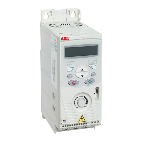
Компактные преобразователи частоты серии ACS150 разработаны для управления низковольтными асинхронными электродвигателями переменного тока в простых применениях, не требующих точного поддержания момента, скорости или какой-либо внешней технологической переменной, но допускающих работу с различными типами нагрузки. Встроенная панель управления с жидкокристаллическим дисплеем, кнопками и потенциометром, делает процесс настройки и эксплуатации привода очень простым.
- Ускоренная и упрощенная настройка и ввод в эксплуатацию
- Монтаж на вертикальной поверхности с помошью винтов, монтаж на DIN-рейку, возможность установки узкой (торцом) или широкой (боком) стороной наружу
- Встроенная панель управления с жидкокристаллическим дисплеем
- Встроенный потенциометр
- Встроенный фильтр ЭМС
- Встроенный тормозной прерыватель (чоппер)
- Дополнительное задающее напряжение + 10В
- Степень защиты IP 20
 Переход в раздел технической документации
Запросить дополнительную информацию и цены
Модельный ряд
Серия ACS150 напряжение сети 200-240 B (1 фаза)
| Модель | Мощность, кВт |
Ток, А |
Время торможения, с | Габариты (ШхВхГ), мм |
Цена | |
|---|---|---|---|---|---|---|
| ACS150-01E-02A4-2 | 0.37 | 2.4 | 0,1-1800 | 169x70x142 | 7 416 р. | купить |
| ACS150-01E-04A7-2 | 0.75 | 4.7 | 0,1-1800 | 169x70x142 | 9 422 р. | купить |
| ACS150-01E-06A7-2 | 1.1 | 6.7 | 0,1-1800 | 169x70x142 | 10 980 р. | купить |
| ACS150-01E-07A5-2 | 1.5 | 7.5 | 0,1-1800 | 169x105x142 | 12 007 р. | купить |
| ACS150-01E-09A8-2 | 2.2 | 9.8 | 0,1-1800 | 169x105x142 | 13 617 р. | купить |
Серия ACS150 напряжение сети 200-240 B (3 фазы)
| Модель | Мощность, кВт |
Ток, А |
Время торможения, с | Габариты (ШхВхГ), мм |
Цена | |
|---|---|---|---|---|---|---|
| ACS150-03E-02A4-2 | 0.37 | 2.4 | 0,1-1800 | 169x70x142 | 10 301 р. | купить |
| ACS150-03E-03A5-2 | 0.55 | 3.5 | 0,1-1800 | 169x70x142 | 10 838 р. | купить |
| ACS150-03E-04A7-2 | 0.75 | 4.7 | 0,1-1800 | 169x70x142 | 13 033 р. | купить |
| ACS150-03E-06A7-2 | 1.1 | 6.7 | 0,1-1800 | 169x70x142 | 15 275 р. | купить |
| ACS150-03E-07A5-2 | 1.5 | 7.5 | 0,1-1800 | 169x70x142 | 16 597 р. | купить |
Серия ACS150 напряжение сети 380-480 B (3 фазы)
| Модель | Мощность, кВт |
Ток, А |
Время торможения, с | Габариты (ШхВхГ), мм |
Цена | |
|---|---|---|---|---|---|---|
| ACS150-03E-01A2-4 | 0.37 | 1.2 | 0,1-1800 | 169x70x142 | 8 885 р. | купить |
| ACS150-03E-01A9-4 | 0.55 | 1.9 | 0,1-1800 | 169x70x142 | 9 470 р. | купить |
| ACS150-03E-02A4-4 | 0.75 | 2.4 | 0,1-1800 | 169x70x142 | 10 349 р. | купить |
| ACS150-03E-03A3-4 | 1.1 | 3.3 | 0,1-1800 | 169x70x142 | 12 007 р. | купить |
| ACS150-03E-04A1-4 | 1.5 | 4.1 | 0,1-1800 | 169x70x142 | 14 060 р. | купить |
| ACS150-03E-05A6-4 | 2.2 | 5.6 | 0,1-1800 | 169x70x142 | 15 080 р. | купить |
| ACS150-03E-07A3-4 | 3 | 7.3 | 0,1-1800 | 169x70x142 | 17 081 р. | купить |
| ACS150-03E-08A8-4 | 4 | 8.8 | 0,1-1800 | 169x70x142 | 19 429 р. | купить |
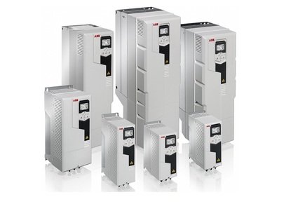
Компонентные приводы ABB
Компонентные приводы ABB предназначены для использования в широком спектре машинных применений, таких как миксеры, конвейеры, вентиляторы или насосы, а также в любом другом технологическом процессе, где требуется регулировать скорость приводного двигателя.
Компонентные приводы ABB отвечают требованиям OEM клиентов, производителей машинного оборудования и изготовителей щитового оборудования. Эти приводы могут быть приобретены у большинства дистрибьютеров оборудования ABB. Компонентные приводы просты в подборе и обладают широким диапазоном встроенных функций в стандартном исполнении такими как ПИД-управление, встроенный тормозной прерыватель, встроенная панель управления и потенциометр для регулирования скорости.
Особенности преобразователя частоты ABB компактной серии ACS150
| Характеристика | Достоинство | Преимущество |
|---|---|---|
| Доступность и сервис | Приводы широко распространены и постоянно содержатся на складе в 4 регионах. Отличная глобальная сеть сервиса и поддержки, которая является одной из самых крупных в индустрии. |
Быстрая и надежная доставка с хорошей технической поддержкой в любой стране мира. |
| Встроенная LCD панель управления и встроенный потенциометр | Понятный буквенно-цифровой дисплей – прост в настройке и эксплуатации. | Экономия времени. |
| Встроенный ЭМС-фильтр | Высокая электромагнитная совместимость привода | Низкие ЭМС излучения в любой среде использования |
| Встроенный тормозной прерыватель в стандартной комплектации | Нет необходимости использовать внешний тормозной прерыватель | Экономия места, уменьшение затрат на установку оборудования |
| Большие установочные возможности | Монтаж на DIN рейку или с помощью болтов, боковая установка или установка бок-о-бок | Один и тот же привод может быть использован в различных проектах с уменьшением затрат на установку и времени монтажа |
| Устройство FlashDrop | Ускоренная и упрощенная настройка и ввод в эксплуатацию – важно для массового производства и технического обслуживания. FlashDrop может загружать параметры в обесточенный привод, устройство также может копировать параметры с одного привода в другой и выгружать параметры в PC. | Быстрый, безопасный и практически безотказный способ настройки параметров привода, не требующий подачи электропитания. Запатентовано. |
| ПИД регулятор | Регулирует производительность привода в соответствии с требованиями технологического процесса. | Повышенные показатели на выходе привода, устройчивость и точность |
| Платы, покрытые лаком | Покрытие лаком позволяет защитить электронику от вредных воздействия, включая статическое электричество и и примесей, содержащихся в воздухе, в том числе и от конденсата | Снижает количество работ по обслуживанию благодаря хорошей защите электронных компонентов |
Типовые применения частотного преобразователя ABB серия ACS150
Компонентые приводы ABB позволяют улучшить регулирование скорости в большинстве применений.
Источник
Преобразователи частоты ABB компактная серия ACS150
Компактные преобразователи частоты серии ACS150 разработаны для управления низковольтными асинхронными электродвигателями переменного тока в простых применениях, не требующих точного поддержания момента, скорости или какой-либо внешней технологической переменной, но допускающих работу с различными типами нагрузки. Встроенная панель управления с жидкокристаллическим дисплеем, кнопками и потенциометром, делает процесс настройки и эксплуатации привода очень простым.
- Ускоренная и упрощенная настройка и ввод в эксплуатацию
- Монтаж на вертикальной поверхности с помошью винтов, монтаж на DIN-рейку, возможность установки узкой (торцом) или широкой (боком) стороной наружу
- Встроенная панель управления с жидкокристаллическим дисплеем
- Встроенный потенциометр
- Встроенный фильтр ЭМС
- Встроенный тормозной прерыватель (чоппер)
- Дополнительное задающее напряжение + 10В
- Степень защиты IP 20
Переход в раздел технической документации
Запросить дополнительную информацию и цены
Модельный ряд
Серия ACS150 напряжение сети 200-240 B (1 фаза)
| Модель | Мощность, кВт |
Ток, А |
Время торможения, с | Габариты (ШхВхГ), мм |
Цена | |
|---|---|---|---|---|---|---|
| ACS150-01E-02A4-2 | 0.37 | 2.4 | 0,1-1800 | 169x70x142 | 7 405 р. | купить |
| ACS150-01E-04A7-2 | 0.75 | 4.7 | 0,1-1800 | 169x70x142 | 9 399 р. | купить |
| ACS150-01E-06A7-2 | 1.1 | 6.7 | 0,1-1800 | 169x70x142 | 10 956 р. | купить |
| ACS150-01E-07A5-2 | 1.5 | 7.5 | 0,1-1800 | 169x105x142 | 11 977 р. | купить |
| ACS150-01E-09A8-2 | 2.2 | 9.8 | 0,1-1800 | 169x105x142 | 13 588 р. | купить |
Серия ACS150 напряжение сети 200-240 B (3 фазы)
| Модель | Мощность, кВт |
Ток, А |
Время торможения, с | Габариты (ШхВхГ), мм |
Цена | |
|---|---|---|---|---|---|---|
| ACS150-03E-02A4-2 | 0.37 | 2.4 | 0,1-1800 | 169x70x142 | 10 272 р. | купить |
| ACS150-03E-03A5-2 | 0.55 | 3.5 | 0,1-1800 | 169x70x142 | 10 809 р. | купить |
| ACS150-03E-04A7-2 | 0.75 | 4.7 | 0,1-1800 | 169x70x142 | 13 004 р. | купить |
| ACS150-03E-06A7-2 | 1.1 | 6.7 | 0,1-1800 | 169x70x142 | 15 240 р. | купить |
| ACS150-03E-07A5-2 | 1.5 | 7.5 | 0,1-1800 | 169x70x142 | 16 555 р. | купить |
Серия ACS150 напряжение сети 380-480 B (3 фазы)
| Модель | Мощность, кВт |
Ток, А |
Время торможения, с | Габариты (ШхВхГ), мм |
Цена | |
|---|---|---|---|---|---|---|
| ACS150-03E-01A2-4 | 0.37 | 1.2 | 0,1-1800 | 169x70x142 | 8 862 р. | купить |
| ACS150-03E-01A9-4 | 0.55 | 1.9 | 0,1-1800 | 169x70x142 | 9 446 р. | купить |
| ACS150-03E-02A4-4 | 0.75 | 2.4 | 0,1-1800 | 169x70x142 | 10 325 р. | купить |
| ACS150-03E-03A3-4 | 1.1 | 3.3 | 0,1-1800 | 169x70x142 | 11 977 р. | купить |
| ACS150-03E-04A1-4 | 1.5 | 4.1 | 0,1-1800 | 169x70x142 | 14 024 р. | купить |
| ACS150-03E-05A6-4 | 2.2 | 5.6 | 0,1-1800 | 169x70x142 | 15 045 р. | купить |
| ACS150-03E-07A3-4 | 3 | 7.3 | 0,1-1800 | 169x70x142 | 17 045 р. | купить |
| ACS150-03E-08A8-4 | 4 | 8.8 | 0,1-1800 | 169x70x142 | 19 382 р. | купить |
Компонентные приводы ABB
Компонентные приводы ABB предназначены для использования в широком спектре машинных применений, таких как миксеры, конвейеры, вентиляторы или насосы, а также в любом другом технологическом процессе, где требуется регулировать скорость приводного двигателя.
Компонентные приводы ABB отвечают требованиям OEM клиентов, производителей машинного оборудования и изготовителей щитового оборудования. Эти приводы могут быть приобретены у большинства дистрибьютеров оборудования ABB. Компонентные приводы просты в подборе и обладают широким диапазоном встроенных функций в стандартном исполнении такими как ПИД-управление, встроенный тормозной прерыватель, встроенная панель управления и потенциометр для регулирования скорости.
Особенности преобразователя частоты ABB компактной серии ACS150
| Характеристика | Достоинство | Преимущество |
|---|---|---|
| Доступность и сервис | Приводы широко распространены и постоянно содержатся на складе в 4 регионах. Отличная глобальная сеть сервиса и поддержки, которая является одной из самых крупных в индустрии. |
Быстрая и надежная доставка с хорошей технической поддержкой в любой стране мира. |
| Встроенная LCD панель управления и встроенный потенциометр | Понятный буквенно-цифровой дисплей – прост в настройке и эксплуатации. | Экономия времени. |
| Встроенный ЭМС-фильтр | Высокая электромагнитная совместимость привода | Низкие ЭМС излучения в любой среде использования |
| Встроенный тормозной прерыватель в стандартной комплектации | Нет необходимости использовать внешний тормозной прерыватель | Экономия места, уменьшение затрат на установку оборудования |
| Большие установочные возможности | Монтаж на DIN рейку или с помощью болтов, боковая установка или установка бок-о-бок | Один и тот же привод может быть использован в различных проектах с уменьшением затрат на установку и времени монтажа |
| Устройство FlashDrop | Ускоренная и упрощенная настройка и ввод в эксплуатацию – важно для массового производства и технического обслуживания. FlashDrop может загружать параметры в обесточенный привод, устройство также может копировать параметры с одного привода в другой и выгружать параметры в PC. | Быстрый, безопасный и практически безотказный способ настройки параметров привода, не требующий подачи электропитания. Запатентовано. |
| ПИД регулятор | Регулирует производительность привода в соответствии с требованиями технологического процесса. | Повышенные показатели на выходе привода, устройчивость и точность |
| Платы, покрытые лаком | Покрытие лаком позволяет защитить электронику от вредных воздействия, включая статическое электричество и и примесей, содержащихся в воздухе, в том числе и от конденсата | Снижает количество работ по обслуживанию благодаря хорошей защите электронных компонентов |
Типовые применения частотного преобразователя ABB серия ACS150
Компонентые приводы ABB позволяют улучшить регулирование скорости в большинстве применений.
Источник
ABB кат алоги, инструкции, программы
Каталоги
Технический каталог Компонентные электроприводы ABB ACS 150 от 0,37 до 4 кВт
Низковольтные приводы переменного тока ACS55, ACS150, ACS310, ACS355, ACS550
Стандартные приводы ABB ACS 310 0,37 — 22 кВт
AББ для высокоточного машиностроения ACSM1, 0,75 — 45 кВт / 1 — 60 л.с.
Электроприводы ABB ACS 355 для механизмов общего назначения 0,37 — 22 кВт
Промышленные приводы АББ ACS800, мультидрайв от 1,5 до 5600 кВт
Низковольтные приводы переменного тока ABB ACS 55, ACS 150, ACS 310, ACS 355, ACS 550
Промышленные приводы AББ ACS800, одиночные приводы, от 0,55 до 5600 кВт
Каталог запчастей ABB ACS 2000 англ.
Технический спецификации ABB ACS 2000
Техническое руководство ABB ACS 5000 англ
Руководства
Руководство по микропрограммному обеспечению Стандартная программа управления ACS800 7. х
Руководство по монтажу и вводу в эксплуатацию Инверторные блоки ACS800-107, монтируемые в шкафу ( от 1,5 до 5430 кВт )
Руководство по эксплуатации ACS800-307 и ACS800-507 Диодные блоки питания (DSU), монтируемые в шкафу
Руководство по эксплуатации Приводы ACH550-01 (0,75-90 кВт) Приводы ACH550-UH (1-150 л.с.)
Приводные модули ACQ810-04 (0,37 – 45 кВт, 0,5 – 60 л.с.)
Руководство по микропрограммному обеспечению Стандартная программа управления насосом для приводов ACQ810
Руководство пользователя преобразователей частоты ACS 100 мощностью от 0.12 до 2.2 кВт
Руководство пользователя Приводы ACS150 (0,37-4 кВт, 0,5-5 л.с.)
Приводы, монтируемые в шкафу ACS800 Механический монтаж
Руководство по эксплуатации Приводы ACH550-02 (110-355 кВт) Приводы ACH550-U2 (125-550 л.с.)
Руководство по вводу в эксплуатацию Приводные модули ACQ810-04
Руководство по эксплуатации приводов переменного тока типа ACS50 0,18-0,75 кВт
Руководство пользователя преобразователей частоты типа ACS 140 Мощность: 0,12 – 2,2 кВт
Руководство пользователя преобразователей частоты типа ACS 160 мощностью от 0,55 до 2,2 кВт
Руководство пользователя Приводы ACS350 (0,37-7,5 кВт, 0,5-10 л.с.)
Руководство по эксплуатации Приводы ACS310
Руководство пользователя Приводы ACS350 (0,37-7,5 кВт, 0,5-10 л.с.)
Руководство по установке ACS 400
Руководство по эксплуатации Приводы ACS550-01 (0,75-110 кВт) Приводы ACS550-U1 (1-150 л.с.)
Руководство по монтажу и вводу в эксплуатацию преобразователи частоты ACS/ACC/ACP 604/607/627 мощностью от 55 до 630 кВт (от 75 до 700 л. с.)
Руководство пользователя для преобразователей частоты типа ACS 400 в диапазоне от 2,2 до 37 кВт
Frequency converters ACS 501 2.2 to 75 kW
Руководство по микропрограммному обеспечению ACS580, стандартная программа управления
Руководство пользователя ABB ACS 300 англ.
ABB ACS 800
Руководство по монтажу и вводу в эксплуатацию Приводы ACS800-01 (от 0,55 до 110 кВт) Приводы ACS800-U1 (от 0,75 до 150 л.с.)
Руководство по монтажу и вводу в эксплуатацию Приводы ACS800-07 (от 45 до 560 кВт) Приводы ACS800-U7 (от 50 до 600 л.с.)
Руководство по микропрограммному обеспечению Стандартная прикладная программа ACS800 7.x
Руководство по монтажу и вводу в эксплуатацию Приводные модули ACS850-04 (55 – 160 кВт, 75 – 200 л.с.)
Руководство по монтажу и вводу в эксплуатацию Приводы ACS800-02 (от 45 до 500 кВт) Приводы ACS800-U2 (от 60 до 600 л.с.)
Руководство по монтажу и вводу в эксплуатацию Приводы ACS800-07 (от 500 до 2800 кВт)
Руководство по прикладному программированию Адаптивная программа
Руководство по микропрограммному обеспечению ACS850, Стандартная программа управления
Руководство по монтажу и вводу в эксплуатацию Приводные модули ACS880-04 (200 – 710 кВт, 300 – 700 л.с.)
Руководство по монтажу и вводу в эксплуатацию Приводы ACS880-07 (45–560 кВт)
Руководство по микропрограммному обеспечению Основная программа управления ACS880
Источник