-
Contents
-
Table of Contents
-
Troubleshooting
-
Bookmarks
Quick Links
User’s
Manual
Yokogawa Electric Corporation
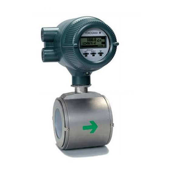
ADMAG AXF Series
F
Fieldbus Communication Type
OUNDATION
Magnetic Flowmeter
IM01E20F02-01E
IM01E20F02-01E
3rd Edition
Related Manuals for YOKOGAWA ADMAG AXF Series
Summary of Contents for YOKOGAWA ADMAG AXF Series
-
Page 1
User’s Manual ADMAG AXF Series Fieldbus Communication Type OUNDATION Magnetic Flowmeter IM01E20F02-01E IM01E20F02-01E 3rd Edition Yokogawa Electric Corporation… -
Page 2: Table Of Contents
AI Function Block Parameters …………5-4 DI Function Block Parameters …………5-7 Integral LCD Indicator …………….. 5-8 5.6.1 Flow Data Display ……………. 5-8 5.6.2 Display Modes …………….5-10 IM 01E20F02-01E 3rd Edition: June 2012 All Rights Reserved, Copyright © 2006, Yokogawa Electric Corporation…
-
Page 3
CONTENTS IN-PROCESS OPERATION …………….6-1 Mode Transition ……………… 6-1 Generation of Alarm …………….6-1 6.2.1 Indication of Alarm …………… 6-1 6.2.2 Alarms and Events …………… 6-1 Simulation Function …………….6-2 DEVICE INFORMATION …………….7-1 DEVICE STATUS …………….7-1 Status of each parameter in failure mode ………. 7-4 PARAMETER LISTS ……………… -
Page 4
CONTENTS APPENDIX 2. INTEGRATOR (IT) BLOCK …………A-6 A2.1 Schematic Diagram of Integrator Block ……….A-6 A2.2 Input Process Section …………….. A-7 A2.2.1 Determining Input Value Statuses ……….A-7 A2.2.2 Converting the Rate …………..A-7 A2.2.3 Converting Accumulation …………. A-8 A2.2.4 Determining the Input Flow Direction ……….. -
Page 5
CONTENTS APPENDIX 5. PID BLOCK …………….A-32 A5.1 Function Diagram …………….A-32 A5.2 Functions of PID Block …………..A-32 A5.3 Parameters of PID Block …………..A-33 A5.4 PID Computation Details …………..A-35 A5.4.1 PV-proportional and -derivative Type PID (I-PD) Control Algorithm ……………. A-35 A5.4.2 PID Control Parameters …………. -
Page 6: Introduction
1. INTRODUCTION INTRODUCTION This manual is for the ADMAG AXF Series Magnetic WARNING Flowmeter Remote Converter F fieldbus OUNDATION Communication Type. The F fieldbus OUNDATION Indicates a potentially hazardous situation which, communication type is based on the same ADMAG if not avoided, could result in death or serious AXF technology used in the BRAIN/HART communi- injury.
-
Page 7: Safe Use Of This Product
• The wiring of the magnetic flowmeter must be (f) Modification performed by expert engineer or skilled personnel. • Yokogawa will not be liable for malfunctions or No operator shall be permitted to perform proce- damage resulting from any modification made to this dures relating to wiring.
-
Page 8: Warranty
— Use of the product in question in a location not conforming to the standards specified by Yokogawa, or due to improper maintenance of the installation location. — Failure or damage due to modification or repair by any party except Yokogawa or an approved representative of Yokogawa.
-
Page 9: About Fieldbus
• Switches two main inputs of different measurement the specification standardized by The Fieldbus Founda- ranges and combines the result with three auxiliary tion, and provides interoperability between Yokogawa inputs through the selected compensation function to devices and those produced by other manufacturers.
-
Page 10: Wiring System Configuration
2. ABOUT FIELDBUS 2.4 Wiring System Configuration The number of devices that can be connected to a single bus and the cable length vary depending on system design. When constructing systems, both the basic and overall design must be carefully considered to achieve optimal performance.
-
Page 11: Getting Started
3. GETTING STARTED GETTING STARTED Fieldbus is fully dependent upon digital communica- Refer to Yokogawa when making arrangements to tion protocol and differs in operation from conven- purchase the recommended equipment. tional 4 to 20 mA transmission and the BRAIN Connect the devices as shown in Figure 3.1.
-
Page 12: Host Setting
3. GETTING STARTED 3.2 Host Setting 0x00 Not used To activate Fieldbus, the following settings are 0x0F 0x10 required for the host. Bridge device 0x13 0x14 LM device V(FUN) IMPORTANT Unused V(NUN) Do not turn off the power immediately after setting.
-
Page 13: Bus Power On
59454300B Using the host device display function, check that the (594543 is the manufacturer number of Yokogawa AXF is in operation on the bus. Electric Corporation, and 000B is the AXF device The device information, including PD tag, Node number, respectively.)
-
Page 14: Continuous Record Of Values
3. GETTING STARTED 3.6 Continuous Record of Values If the host has a function that continuously records the indications, use this function to list the indications (values). Depending on the host being used, it may be necessary to set the schedule of Publish (the function that transmits the indication on a periodic basis).
-
Page 15: Configuration
4. CONFIGURATION CONFIGURATION • Terminator This chapter describes how to adapt the function and performance of the AXF to suit specific applications. Fieldbus requires two terminators. Refer to the Because multiple devices are connected to Fieldbus, it supplier for details of terminators that are attached is important to carefully consider the device require- to the host.
-
Page 16: Definition Of Combining Function Blocks
4. CONFIGURATION Table 4.2 Operation Parameter Values of the AXF to be bus control function allocated from a larger address Set to LM Devices number (247) side respectively. Place the AXF in the range of the BASIC device. When the AXF is used as Symbol Parameters Description and Settings…
-
Page 17: Setting Of Tags And Addresses
4. CONFIGURATION 4.4 Setting of Tags and A maximum of 30 ms is taken for execution of AI block. For scheduling of communications for combina- Addresses tion with the next function block, the execution is so This section describes the steps in the procedure to set arranged as to start after a lapse of longer than 30 ms.
-
Page 18: Communication Setting
4. CONFIGURATION 4.5 Communication Setting Table 4.4 VCR Static Entry Sub- Parameter Description To set the communication function, it is necessary to index change the database residing in SM-VFD. FasArTypeAndRole Indicates the type and role of communication (VCR). The 4.5.1 VCR Setting following 4 types are used for AXF.
-
Page 19: Function Block Execution Control
4. CONFIGURATION 4.6 Block Setting Sub- Parameter Description index Set the parameter for function block VFD. FasDllSubsriberTime Not used for AXF. WindowSize 4.6.1 Link Object FasDllSubscriber Not used for AXF. SynchronizationDlcep A link object combines the data voluntarily sent by the function block with the VCR.
-
Page 20: Trend Object
4. CONFIGURATION 4.6.2 Trend Object SMIB DI2 OUT (System Transducer Resource Management AI OUT It is possible to set the parameter so that the function block block DI1 OUT Information block automatically transmits Trend. AXF has seven Base) NMIB Trend objects, six of which are used for Trend in Alert (Network FBOD…
-
Page 21
4. CONFIGURATION Table 4.11 View Object for Resource Block (byte) (byte) Relative VIEW VIEW VIEW VIEW Relative VIEW VIEW VIEW VIEW Parameter Parameter Index Index ST_REV MAX_NOTIFY TAG_DESC LIM_NOTIFY STRATEGY CONFIRM_TIME ALERT_KEY WRITE_LOCK MODE_BLK UPDATE_EVT BLOCK_ERR BLOCK_ALM RS_STATE ALARM_SUM TEST_RW ACK_OPTION DD_RESOURCE WRITE_PRI… -
Page 22
4. CONFIGURATION Table 4.12 View Object for Transducer Block (byte) (byte) VIEW VIEW VIEW VIEW VIEW VIEW VIEW VIEW VIEW VIEW VIEW VIEW VIEW VIEW VIEW VIEW VIEW VIEW VIEW VIEW VIEW VIEW Relative Relative Parameter Mnemonic Parameter Mnemonic Index Index ST_REV VELOCITY_CHECK… -
Page 23
4. CONFIGURATION Table 4.13 View Object for AI Function Block Table 4.14 View Object for DI (DI1, DI2) Function Block (byte) (byte) Relative VIEW Relative VIEW VIEW VIEW VIEW VIEW VIEW VIEW Parameter Parameter Index Index ST_REV ST_REV TAG_DESC TAG_DESC STRATEGY STRATEGY ALERT_KEY… -
Page 24
4. CONFIGURATION Table 4.15 View Object for (IT1, IT2) Function Block Table 4.16 View Object for AR Function Block (byte) (byte) Relative VIEW Relative VIEW VIEW VIEW VIEW VIEW VIEW VIEW Parameter Parameter Index Index ST_REV ST_REV TAG_DESC TAG_DESC STRATEGY STRATEGY ALERT_KEY ALERT_KEY… -
Page 25: Function Block Parameters
4. CONFIGURATION Table 4.17 Indexes of View for Each Block VIEW_1 VIEW_2 VIEW_3 VIEW_4 Resourse Block 40100 40101 40102 40103 Transducer Block 40200 40201 40202 40203 AI Function Block 40400 40401 40402 40403 DI1 Function Block 40600 40601 40602 40603 DI2 Function Block 40610 40611…
-
Page 26: Explanation Of Basic Items
5. EXPLANATION OF BASIC ITEMS EXPLANATION OF BASIC ITEMS 5.1 Outline 5.2 Setting and Changing Param- eters for the Whole Process This chapter describes basic TR (Transducer block), AI, and DI function block parameter setting, displays of the integral indicator. Refer to Appendixes other IMPORTANT function blocks and LM function.
-
Page 27: Transducer Block Parameters
5. EXPLANATION OF BASIC ITEMS 5.3 Transducer Block Parameters The transducer block sets functions specific to the flow rate measurement of the ADMAG AXF. Figure5.3.1 presents the diagram of the Transducer block. PRIMARY_VALUE Dual freq. Rate limit Flow rate Lowcut (Channel1) operation damping…
-
Page 28
5. EXPLANATION OF BASIC ITEMS DISPLAY_SELECT1, 2, 3: Table 5.3.1 DISPLAY SELECT DISPLAY_SELEC T 1 DISPL AY_SELE CT 2 DISPL AY_SELE CT 3 The display content for the display The display content for the display unit’s The display content for the display unit’s first line. -
Page 29: Ai Function Block Parameters
5. EXPLANATION OF BASIC ITEMS 5.4 AI Function Block Parameters AI Function block parameters can be read or set from the host. Figure5.4.1 presents the diagram of AI Function block. Alarms IO_OPTS.Low cutoff HI,HI_HI LO,LO_LO SIMULATE.Enable LOW_CUT =1 (Enable) FIELD_VAL.Value L_TYPE PV.Value Disable…
-
Page 30
5. EXPLANATION OF BASIC ITEMS OUT: This parameter contains the current measurement value from Transducer Block or configuration adjusted engineering unit and the belonging state in AUTO MODE. OUT contains the value and status set by an operator in MAN MODE. Quality Sub-status Limit… -
Page 31
5. EXPLANATION OF BASIC ITEMS Table 5.4.1 Unit Codes Volume/ Time unit Mass unit Ml/h (65521) Ml/min (65520) kL/s (65522) Ml/d (1355) kL/d (1520) kL/h (1519) kL/min (1518) L/s (1351) L/d (1354) L/h (1353) L/min (1352) m3/d (1350) m3/ h (1349) m3/min (1348) m3/s (1347) cm3/d (1514) -
Page 32: Di Function Block Parameters
5. EXPLANATION OF BASIC ITEMS 5.5 DI Function Block Parameters DI Function block parameters can be read or set from the host. Figure5.5.1 presents the diagram of DI Function block. PV_D Simulate Optional Filter CHANNEL SIMULATE_D Invert PV_FTIME Output OUT_D FIELD_VAL_D Alarms DISC…
-
Page 33: Integral Lcd Indicator
5. EXPLANATION OF BASIC ITEMS 5.6 Integral LCD Indicator Flow Rate Flow rate is displayed together with the units set in Employing 32*132 full dot matrix backlit LCD, XD_SCALE, the maximum number of figures is six. various display can be obtained. 5.6.1 Flow Data Display — 1 2 3 .
-
Page 34
5. EXPLANATION OF BASIC ITEMS Flow Rate Unit Display on LCD Flow Rate Unit Display is shown by the following table corresponding to the XD_SCALE Units Codes. Table 5.6.1 Display Unit Codes LCD Display LCD Display LCD Display LCD Display LCD Display LCD Display LCD Display… -
Page 35: Display Modes
5. EXPLANATION OF BASIC ITEMS Arithmetic Out 1 2 3 The display is given in the same manner as Integrator l / h v e l A D H Out, decimal point is set by «AR:OUT_RANGE.Decimal_Point». F0515.eps Desimal Point AR:OUT_RANGE.Decimal_Point AR:OUT_RANGE.Decimal_Point Example Level1 : Adhesion Level2…
-
Page 36
5. EXPLANATION OF BASIC ITEMS Alarm Display 1 0 0 l / h I T 2 2 3 4 5 6 F o u n d a t i o n F i e l d b u s C O M Alarm generated P r o i p e… -
Page 37: Data Display
5. EXPLANATION OF BASIC ITEMS Category Category Alarm Message Alarm Message Countermeasure Message Countermeasure Message Alarm Description Alarm Description 10:uP Fault Microprocessor (CPU) failure 11:EEPROM Fault EEPROM failure Contact nearest office or service center 12:A/D(H) Fault 13:A/D(L) Fault A/D converter failure 14:A/D(Z) Fault 15:Coil Open Cut the power and check coil &…
-
Page 38
5. EXPLANATION OF BASIC ITEMS 9 9 9 l / h I T 1 1 2 3 4 5 6 9 9 9 l / h 2 3 5 5 6 I T 1 8 4 : 9 9 9 l / h I T 1 1 2 3 6 5 6… -
Page 39: In-Process Operation
6. IN-PROCESS OPERATION IN-PROCESS OPERATION 6.2.2 Alarms and Events This chapter describes the procedure performed when changing the operation of the function block of the The following alarms or events can be reported by the AXF in process. AXF if Link object and VCR static entry are set. Analog Alerts (Generated when a process value 6.1 Mode Transition exceeds threshold)
-
Page 40: Simulation Function
6. IN-PROCESS OPERATION 6.3 Simulation Function The simulation function simulates the input of a function block and lets it operate as if the data was received from the transducer block. It is possible to conduct testing for the downstream function blocks or alarm processes.
-
Page 41: Device Information
7. DEVICE INFORMATION DEVICE INFORMATION 7.1 DEVICE STATUS Device status for the AXF are indicated by using parameter DEVICE_STATUS_1 to DEVICE_STATUS_7 (index 1045 to 1052) in Resource Block. Table 7.1 Contents of DEVICE_STATUS_1 (Index 1045) Table 7.2 Contents of DEVICE_STATUS_2 (Index 1046) Indicator description Indicator…
-
Page 42
7. DEVICE INFORMATION Table 7.3 Contents of DEVICE_STATUS_3 (Index 1047) Table 7.5 Contents of DEVICE_STATUS_5 (Index 1049) Indicator description Indicator description 0x00000001 50:Span > 10m/s Span flow velocity setting is 11 m/s or more 0x00000001 30:Sig Overflow Input signal error 0x00000002 51:Span <… -
Page 43
7. DEVICE INFORMATION Table 7.7 Contents of DEVICE_STATUS_7 (Index 1051) Indicator description 0x00000001 130:AI Non-Schedule AI Block not scheduled 0x00000002 131:IT1 Non-Schedule IT1 Block not scheduled 0x00000004 132:IT2 Non-Schedule IT2 Block not scheduled 0x00000008 133:DI1 Non-Schedule DI1 Block not scheduled 0x00000010 134:DI2 Non-Schedule DI2 Block not scheduled… -
Page 44: Status Of Each Parameter In Failure Mode
7. DEVICE INFORMATION 7.2 Status of each parameter in failure mode Following tables summarize the value of AXF parameters and LCD display indicates an Alarm. Table 7.9 Alarm Summary BLOCK_ Primary Primary Value BLOCK_ Primary Primary Value Category Alarm ERROR Category Alarm ERROR…
-
Page 45: Parameter Lists
8. PARAMETER LISTS PARAMETER LISTS Note: The Write Mode column contains the modes in which each parameter is write enabled. O/S: Write enabled in O/S mode. MAN: Write enabled in Man mode and O/S mode. AUTO: Write enabled in Auto mode, Man mode, and O/S mode. Resource Block Relative Factory…
-
Page 46
This alert is generated if the write lock parameter is cleared. 1041 ITK_VER Version number of interoperability test by Fieldbus Foundation applied to AXF. 1042 SOFT_REV AXF software revision number. 1043 SOFT_DESC Yokogawa internal use. 1044 SIM_ENABLE_MSG Spaces Auto Software switch for simulation function. T0801-2.EPS IM 01E20F02-01E… -
Page 47
8. PARAMETER LISTS Relative Factory Write Index Parameter Name Explanation Index Default Mode 1045 DEVICE_STATUS_1 Device status for details, refer to Table 7.1. 1046 DEVICE_STATUS_2 Device status for details, refer to Table 7.2. 1047 DEVICE_STATUS_3 Device status for details, refer to Table 7.3. 1048 DEVICE_STATUS_4 Device status for details, refer to Table 7.4. -
Page 48: Transducer Block
METHOD Static weigh 100=volumetric 101=static weigh 102=dynamic weigh 255=other 2024 SENSOR_CAL_LOC Yokogawa Sets/indicates the location of the last sensor calibration. 2025 SENSOR_CAL_DATE 0, 0, 0, 0, 0, 0 Sets/indicates the date of the last sensor calibration. 2026 SENSOR_CAL_WHO Yokogawa Sets/indicates the name of the person responsible for the last sensor calibration.
-
Page 49
8. PARAMETER LISTS Relative Factory Write Index Parameter Name Explanation Index Default Mode 2027 LIN_TYPE 1: linear with input The linearization type of sensor output. AXF is «linear with input» 2028 SECONDARY_ N/A. For the future use. VALUE SECONDARY_ 2029 1061: m/s N/A. -
Page 50
8. PARAMETER LISTS Relative Factory Write Index Parameter Name Explanation Index Default Mode 2048 VELOCITY_CHECK This parameter is used in order to display the span velocity corresponding to PV_SCALE. E100. 2049 DENSITY_UNIT 1097: kg/m This parameter selects the units for density as required when making settings using MASS_FLOW_DENSITY. -
Page 51
8. PARAMETER LISTS Relative Factory Write Index Parameter Name Explanation Index Default Mode 2064 SWITCH_1_TARGET 1: Adhesion Alarm This parameter selects the input channel used to LIMSW_1_VALUE_D. 1: Adhesion Alarm 2: Adhesion Warning Indicate the value of switch 2, which switches ON and OFF SWITCH_2_ 2065 depending on the digital value of the target input parameter… -
Page 52
8. PARAMETER LISTS Relative Factory Write Index Parameter Name Explanation Index Default Mode 2085 ALARM_SUM Block Alarm status is shown by this parameter. Valid range is bit 0: Discrete alm, bit7: Block alarm (only bit 0 and bit 7 are effective). Initial value is Current: 0, Unacknowledged: 0, Unreported: 0, Disable: 0X0000 (all alarms are enable). -
Page 53: Ai Function Block
8. PARAMETER LISTS AI Function Block Relative Factory Write Index Parameter Name Explanation Index Default Mode 4000 Block Hedder TAG=»AI» Information on this block such as Block Tag, DD Revision, Execution Time etc. 4001 ST_REV The revision level of the static data associated with the function block.
-
Page 54
8. PARAMETER LISTS Relative Factory Write Index Parameter Name Explanation Index Default Mode Raw value of the field device in percent of the PV range, with a 4019 FIELD_VAL Bad — O/S status reflecting the Transducer condition, before signal characterization (L_TYPE), filtering (PV_FTIME), or low cut (LOW_CUT). -
Page 55: Dl Function Block
8. PARAMETER LISTS Dl Function Block Factory Write Relative Index Index Parameter Name Explanation Default Mode Index 6000 6100 Block Header Information on this block such as Block Tag, DD Revision, DI1: TAG=»DI1″ Execution Time etc. DI2: TAG=»DI2″ 6001 6101 ST_REV The revision level of the static data of the DI block.
-
Page 56: General Specifications
9. GENERAL SPECIFICATIONS GENERAL SPECIFICATIONS STANDARD SPECIFICATIONS STANDARD PERFORMANCE Accuracy: For items other than those described below, Note: The accuracy of a product before shipment is refer to IM 01E20D01-01E, IM 01E20C02-01E. defined as totalized value at the result of calibration test in our water actual flow test facility.
-
Page 57: Optional Specifications
9. GENERAL SPECIFICATIONS MODEL AND SUFFIX CODE Integral Flowmeter AXF: Remote Converter AXFA14: AXFA14 -F — (Note1) “F” following the first dash indicates that the output is digital communication compliant with the F OUNDATION fieldbus protocol. 9.2 OPTIONAL SPECIFICATIONS For options other than below, refer to IM 01E20D01-01E and IM 01E20C02-01E (Optional codes C1, C2, C3, EM, G11 and G13 are unable to select).
-
Page 58: Terminal Connection
9. GENERAL SPECIFICATIONS 9.3 TERMINAL CONNECTION CAUTION Integral Flowmeter AXF Do not connect to these terminals which are Terminal configuration marked “CAUTION Don’t connect”. F01.EPS Terminal wiring Terminal Description Symbols Functional grounding N/– Power supply Fieldbus communication signal FB– Protective grounding (Outside of the terminal) T06.EPS…
-
Page 59: Maintenance
10. MAINTENANCE 10. MAINTENANCE For maintenance items, please refer to user’s manual IM 01E20D01-01E or IM 01E20C02-01E. 10-1 IM 01E20F02-01E…
-
Page 60
APPENDIX 1. APPLICATION, SETTING AND CHANGE OF BASIC PARAMETERS APPENDIX 1. APPLICATION, SETTING AND CHANGE OF BASIC PARAMETERS A1.1 Applications and Selection of Basic Parameters Setting Item (applicable parameters) Summary Sets PD_Tag. Up to 32 alphanumeric characters can be set. Tag No.(PD_TAG) Sets the range of input from the transducer block corresponding to the 0% and 100% points in operation within the AI function block. -
Page 61: Appendix 1. Application, Setting And Change Of Basic Parameters
APPENDIX 1. APPLICATION, SETTING AND CHANGE OF BASIC PARAMETERS A1.2 Setting and Change of IMPORTANT Basic Parameters Do not turn the power OFF immediately after This section describes the procedure taken to set and parameter setting. When the parameters are change the parameters for each block.
-
Page 62: A1.3 Setting The Ai Function Block
APPENDIX 1. APPLICATION, SETTING AND CHANGE OF BASIC PARAMETERS A1.3 Setting the AI Function (4)Simulation Perform simulation of the AI function block by setting Block the desired value and status of the input to the block. The AI function block outputs the flow rate signals. REMOTE LOOP TEST SWITCH is written to (1)Setting the flow range SIM_ENABLE_MSG(index 1044) parameter of the resource…
-
Page 63: A1.4 Setting The Transducer Block
APPENDIX 1. APPLICATION, SETTING AND CHANGE OF BASIC PARAMETERS A1.4 Setting the Transducer (4)Setting the LCD display Select the data to be displayed on the LCD indicator Block and the display refresh cycle. To access the AXF-specific functions in the transducer block, the Device Description (DD) for AXF needs to Access the DISPLAY_SELECT1-3 parameter and have been installed in the configuration tool used.
-
Page 64: A1.5 Setting The Integrator (It) Function Block
APPENDIX 1. APPLICATION, SETTING AND CHANGE OF BASIC PARAMETERS A1.5 Setting the Integrator (IT) A1.6 Setting the DI Function Function Block Block The Integrator function block output the flow totaliza- DI function blocks output limit switch signals received tion. from the transducer block. Two DI blocks (DI1 and DI2) in each AXF have (1)Setting the unit of totalization independent parameters.
-
Page 65
APPENDIX 2. INTEGRATOR (IT) BLOCK APPENDIX 2. INTEGRATOR (IT) BLOCK The Integrator (IT) block adds two main inputs and OUT.Value = Integration start value + Total integrates them for output. The block compares the Total = Total + Current Integral ∆t integrated or accumulated value to TOTAL_SP and Current Integral = (x + y) -
Page 66: Appendix 2. Integrator (It) Block
APPENDIX 2. INTEGRATOR (IT) BLOCK A2.2 Input Process Section When executed, the Integrator block first performs input processing in the order of: «Determining input status» → «Converting Rate or Accum» → «Determining the input flow direction» Switching between Convert Rate and Convert Accum is made using bit 0 (for IN_1) or bit 1 (for IN_2) of INTEG_OPTS.
-
Page 67: A2.2.3 Converting Accumulation
APPENDIX 2. INTEGRATOR (IT) BLOCK A2.2.3 Converting Accumulation This following describes an example of accumulation conversion. In accumulation conversion, the difference between the value executed previously and the value executed this time is integrated or accumulated. This conversion applies when the output of a function block used as a counter is input to the input process of the Integrator block.
-
Page 68: A2.3.2 Addition
APPENDIX 2. INTEGRATOR (IT) BLOCK A2.3.2 Addition The following three options are available for addition: • TOTAL: Adds two argument values as is. • FORWARD: Adds two argument values, regarding a negative value as «0.» • REVERSE: Adds two argument values, regarding a positive value as «0.»…
-
Page 69
APPENDIX 2. INTEGRATOR (IT) BLOCK Table A2.1 INTEG_TYPE Reset Trigger (Reset if one of the Name Integration Method Integration Range Trip Output following conditions is established) -INF< Total <TOTAL_SP • OUT reaches TOTAL_SP. 0< ATotal <+INF Counting up UP_AUTO(1) • RESET_IN = 1 Starting from «0»… -
Page 70: A2.5 Output Process
APPENDIX 2. INTEGRATOR (IT) BLOCK A2.5 Output Process A2.5.1 Status Determination The same criteria for determining the status of the There are the following three output parameters: output of the Integrator block are used in common for 1. OUT the above three parameters. 2.
-
Page 71: A2.5.2 Determining The Output Value
APPENDIX 2. INTEGRATOR (IT) BLOCK A2.5.2 Determining the Output Value Total: Total of integrated values. This value is retained even if INTEG_TYPE is changed during The value of OUT.Value is determined as follows: integration For counting up (in AUTO). OUT = integration start value (0) + Total If OUT is rewritten in the MAN mode, integration starts with the value rewritten in MAN mode after the For counting down…
-
Page 72: A2.5.3 Mode Handling
APPENDIX 2. INTEGRATOR (IT) BLOCK A2.5.3 Mode Handling Mode Action Output Automatic (AUTO) Normal action Normal output Integration calculation is stopped. You may rewrite a value in OUT. If no value is rewritten, the value just before Manual (MAN) OUT will not be updated unless you running in AUTO is held.
-
Page 73: A2.6.3 Reset Process
APPENDIX 2. INTEGRATOR (IT) BLOCK A2.6.3 Reset Process ii Carry (bit 6 of INTEG_OPTS) The basic reset process sequence is as follows: If this option is enabled while INTEG_TYPE is UP_AUTO or DN_AUTO, the value exceeding the 1.) Snapshot threshold at a reset will be carried into the next 2.) Clearing the integrated values integration.
-
Page 74: A2.7 List Of Integrator Block Parameters
APPENDIX 2. INTEGRATOR (IT) BLOCK A2.7 List of Integrator Block Parameters View Parameter Initial Write Index Definition Name Value Mode 1 2 3 4 Block Tag Information relating to this function block, such as block tag, IT1:TAG=»IT1″ BLOCK_HEADER IT2:TAG=»IT2″ =o/s DD revision, execution time ST_REV —…
-
Page 75
APPENDIX 2. INTEGRATOR (IT) BLOCK View Parameter Initial Write Index Definition Name Value Mode 1 2 3 4 CLOCK_PER 86400.0[sec] Specify the period at which a periodic reset is made. Auto PRE_TRIP 100000.0 Auto Set an allowance applied before an integrated value exceeds the setpoint. N_RESET Indicates the number of resets in the range of 0 to 999999. -
Page 76: Appendix 3. Arithmetic (Ar) Block
APPENDIX 3. ARITHMETIC (AR) BLOCK APPENDIX 3. ARITHMETIC (AR) BLOCK The Arithmetic (AR) block switches two main inputs of different measurement ranges seamlessly and combines the result with three auxiliary inputs through the selected compensation function (10 types) to calculate the output. A3.1 Schematic Diagram of Arithmetic Block The diagram below shows the Arithmetic block schematic.
-
Page 77: A3.2 Input Section
APPENDIX 3. ARITHMETIC (AR) BLOCK A3.2 Input Section PV is a parameter with status information, and PV status is determined by the value of “g.” There are five inputs: IN and IN_LO main inputs and If “g” < 0.5 → The status of IN_LO is used. IN_1, IN_2, and IN_3 auxiliary inputs.
-
Page 78: A3.2.4 Relationship Between The Main Inputs And Pv
APPENDIX 3. ARITHMETIC (AR) BLOCK A3.2.3 INPUT_OPTS · If the status of IN is anything other than “good” and that of “IN_LO” is “good” INPUT_OPTS has an option that handles an input with → PV = IN_LO IN_LO < RANGE_HI “uncertain”…
-
Page 79: A3.3 Computation Section
APPENDIX 3. ARITHMETIC (AR) BLOCK A3.3 Computation Section A3.3.2 Compensated Values In computing equations 1) to 5) in A3.3.1, the value A3.3.1 Computing Equations “f” is restricted by the COMP_HI_LIM or COMP_LO_LIM parameter. In this case, the value “f” This subsection shows computing equations used in the is treated as follows: computation section: If “f”…
-
Page 80: A3.4.1 Mode Handling
APPENDIX 3. ARITHMETIC (AR) BLOCK A3.4.1 Mode Handling A3.4.2 Status Handling The setting of INPUT_OPTS is applied to the input Mode Output status. When INPUT_OPTS is applied, there are cases Auto OUT = PRE_OUT where the PV status becomes “good” even if the status of main inputs is “uncertain”…
-
Page 81: A3.5 List Of The Arithmetic Block Parameters
APPENDIX 3. ARITHMETIC (AR) BLOCK A3.5 List of the Arithmetic Block Parameters View Relative Parameter Write Mode Valid Range Initial Value Description / Remarks Index BLOCK_HEADER TAG=“AR” Information relating to this function block, such as block tag, DD revision, and execution time Indicates the revision level of the set parameters associated with the Arithmetic ST_REV block.
-
Page 82
APPENDIX 3. ARITHMETIC (AR) BLOCK View Relative Parameter Write Mode Valid Range Initial Value Description / Remarks Index Computation algorithm identification no. Value Selection Name Description Flow compensation, linear Flow compensation (linear) Flow compensation, square root Flow compensation (square root) Flow compensation, approximate Flow compensation (approximate expression) BTU flow (*) -
Page 83: Appendix 4. Link Master Functions
APPENDIX 4. LINK MASTER FUNCTIONS APPENDIX 4. LINK MASTER FUNCTIONS A4.1 Link Active Scheduler A link active scheduler (LAS) is a deterministic, centralized bus scheduler that can control communica- tions on an H1 fieldbus segment. There is only one LAS on an H1 fieldbus segment. An AXF supports the following LAS functions.
-
Page 84: A4.3 Transfer Of Las
APPENDIX 4. LINK MASTER FUNCTIONS A4.3 Transfer of LAS LM declares itself as the LAS, then becomes the LAS. (With this procedure, an LM backs up the There are two procedures for an LM to become the LAS as shown in the following figure.) LAS: •…
-
Page 85: A4.4 Lm Functions
APPENDIX 4. LINK MASTER FUNCTIONS A4.4 LM Functions Function Description LM initialization When a fieldbus segment starts, the LM with the smallest [V(ST) × V(TN)] value within the segment becomes the LAS. At all times, each LM is checking whether or not a carrier is on the segment.
-
Page 86: A4.5 Lm Parameters
APPENDIX 4. LINK MASTER FUNCTIONS A4.5 LM Parameters A4.5.1 LM Parameter List The tables below show LM parameters. Meanings of Access column entries: RW = read/write possible; R = read only Default Factory Index Sub-parameter Name Parameter Name Access Remarks Setting (SM) (Sub Index)
-
Page 87
APPENDIX 4. LINK MASTER FUNCTIONS Index Sub-parameter Name Default Factory Access Parameter Name Remarks (SM) (Sub Index) Setting PLME_BASIC_ CHARACTERISTICS 1 ChannelStatisticsSupported 0x00 0x4900000000000000 2 MediumAndDataRatesSupported 1 (0x1) 3 IecVersion 4 NumOfChannels 1 (0x1) 5 PowerMode 0 (0x0) CHANNEL_STATES 1 channel-1 0 (0x0) 2 channel-2 128 (0x80) -
Page 88: A4.5.2 Descriptions For Lm Parameters
APPENDIX 4. LINK MASTER FUNCTIONS (5)MaxTokenHoldTimeArray A4.5.2 Descriptions for LM Parameters An 8(64 byte array variable, in which each set of 2 The following describes LM parameters of an AXF bytes represents the delegation time (set as an octet transmitter. time) assigned to a device.
-
Page 89
SchedulesPer of sub-schedules an LAS IceVersion 0x0403 IEC 4.3 is Schedule schedule can contain. (This is supported. fixed to 1 in the Yokogawa NumOf communication stacks.) Channels ActiveSchedule Indicates the version number of Power 0: Bus-powered; Version the schedule currently executed. -
Page 90: A4.6 Faqs
APPENDIX 4. LINK MASTER FUNCTIONS • 0xFF (true) to Sub- Size Element Description index [bytes] PrimaryLinkMasterFlagVariable (index 364) Version Indicates the version number of in the AXF. the LAS schedule downloaded to the corresponding domain. On a segment where an AXF works as the Macrocycle Indicates the macro cycle of the LAS, another device cannot be connected.
-
Page 91: A5.1 Function Diagram
APPENDIX 5. PID Block APPENDIX 5. PID BLOCK A PID block performs the PID control computation based on the deviation of the measured value (PV) from the setpoint (SV), and is generally used for constant-setpoint and cascaded-setpoint control. A5.1 Function Diagram The figure below depicts the function diagram of a PID block.
-
Page 92: A5.3 Parameters Of Pid Block
APPENDIX 5. PID Block A5.3 Parameters of PID Block NOTE: In the table below, the Write column shows the modes in which the respective parameters can be written. A blank in the Write column indicates that the corresponding parameter can be written in all modes of the PID block. A dash (-) indicates that the corresponding parameter cannot be written in any mode.
-
Page 93
APPENDIX 5. PID Block Default Parameter Index Write Valid Range Description Name (factory setting) SHED_OPT Action to be performed in the event of mode shedding. SHED_OPT defines the changes to be made to MODE.BLK.target and MODE.BLK.actual when the value of RCAS_IN.status or ROUT_IN.status becomes Bad if .MODE_BLK.actual = RCas or ROut. -
Page 94: A5.4 Pid Computation Details
APPENDIX 5. PID Block A5.4 PID Computation Details A5.5 Control Output The final control output value, OUT, is computed A5.4.1 PV-proportional and -derivative based on the change in control output ∆MVn, which is Type PID (I-PD) Control Algorithm calculated at each control period in accordance with the For PID control, the PID block employs the PV- aforementioned algorithm.
-
Page 95: A5.8 Feed-Forward
APPENDIX 5. PID Block A5.8 Feed-forward Block Description Mode Feed-forward is an action to add a compensation output IMan Initialization and manual mode, in which the control signal FF_VAL to the output of the PID control action is suspended. The PID block enters this mode when the specified condition is met computation, and is typically used for feed-forward (see Section A5.14).
-
Page 96: A5.10 Bumpless Transfer
APPENDIX 5. PID Block A5.10 Bumpless Transfer A5.12 External-output Tracking Prevents a sudden change in the control output OUT at External tracking is an action of outputting the value of changes in block mode (MODE_BLK) and at switch- the remote output TRK_VAL set from outside the PID ing of the connection from the control output OUT to block, as illustrated in the figure below.
-
Page 97: A5.14 Initialization And Manual Fallback (Iman)
APPENDIX 5. PID Block A5.15 Manual Fallback Options in Description CONTROL_OPTS Manual fallback denotes an action in which a PID Bypass Enable This parameter allows BYPASS to be set. block changes mode to Man and suspends the control SP-PV Track Equalizes SP to PV when action.
-
Page 98: A5.17 Mode Shedding Upon Computer Failure
APPENDIX 5. PID Block A5.17 Mode Shedding upon NOTE: If a control block is connected as a cascade primary block of the PID block in question, a mode transition of the PID block Computer Failure to Cas occurs in the following sequence due to initialization of the cascade connection: RCas or ROut →…
-
Page 99: A5.19 Example Of Block Connections
APPENDIX 5. PID Block A5.19 Example of Block A5.20 View Object for PID Connections Function Block Relative VIEW VIEW VIEW VIEW Parameter Mnemonic Index ST_REV TAG_DESC STRATEGY ALERT_KEY MODE_BLK BLOCK_ERR BKCAL_IN CAS_IN PV_SCALE OUT_SCALE BKCAL_OUT GRANT_DENY FA0106.EPS CONTROL_OPTS When configuring a simple PID control loop by combining an AXF with a fieldbus valve positioner STATUS_OPTS that contains an AO block, follow the procedure below…
-
Page 100
APPENDIX 5. PID Block Relative VIEW VIEW VIEW VIEW Parameter Mnemonic Index SHED_OPT RCAS_OUT ROUT_OUT TRK_SCALE TRK_IN_D TRK_VAL FF_VAL FF_SCALE FF_GAIN UPDATE_EVT BLOCK_ALM ALARM_SUM ACK_OPTION ALARM_HYS HI_HI_PRI HI_HI_LIM HI_PRI HI_LIM LO_PRI LO_LIM LO_LO_PRI LO_LO_LIM DV_HI_PRI DV_HI_LIM DV_LO_PRI DV_LO_LIM HI_HI_ALM HI_ALM LO_ALM LO_LO_ALM DV_HI_ALM… -
Page 101: A6.1 Benefits Of Software Download
Class 1 devices can continue the specified how to obtain them, visit the following web site. measurement and/or control actions even while http://www.yokogawa.com/fld/fld-top-en.htm software is being downloaded to them. Upon completion of a download, however, the devices will be reset internally to make the new, down-…
-
Page 102: A6.4 Software Download Sequence
APPENDIX 6. SOFTWARE DOWNLOAD CAUTION NOTE The current dissipation of the target field device The download tool can not execute downloading increases transitorily immediately after a down- during other system connects to the system/ load due to erasing of the FlashROM’s contents. network management VFD of the device.
-
Page 103: A6.6 Steps After Activating A Field Device
APPENDIX 6. SOFTWARE DOWNLOAD The device type is “000B” for the AXF . The software name is “ORIGINAL” or “UPDATE.” The former indicates an original file and the latter an update file. Whenever performing a download to update the device revision, obtain the original file. In general, an addition to the parameters or blocks requires a device revision update.
-
Page 104: A6.7 Troubleshooting
APPENDIX 6. SOFTWARE DOWNLOAD A6.7 Troubleshooting For information on the download tool’s error messages, see also the software’s User’s Manual. Table A6.2 Problems after Software Update Symptom Cause Remedy An error occurs before starting a The selected download file is not for the Check SOFTDWN_ERROR in the resource download, disabling the selected field device.
-
Page 105
APPENDIX 6. SOFTWARE DOWNLOAD Table A6.4 Download Error Codes Error Code Detail No error 32768 Unsupported header version Abnormal header size 32769 32770 Abnormal manufacturer ID 32771 Abnormal device family Abnormal device revision 32772 32773 Abnormal vendor specification version 32774 Abnormal number of modules 32775 Abnormal number of bytes in module 1… -
Page 106: A6.9 System/Network Management Vfd Parameters Relating To Software Download
APPENDIX 6. SOFTWARE DOWNLOAD A6.9 System/Network Management VFD Parameters Relating to Soft- ware Download Table A6.5 System/Network Management VFD Parameters Write Mode: R/W = read/write; R = read only Index Default Write Parameter Name Sub-parameter Name Remarks (SM) Index (Factory Set) Mode DWNLD_PROPERTY Download Class…
-
Page 107: A6.10 Comments On System/Network Management Vfd Parameters Relating To Software Download
APPENDIX 6. SOFTWARE DOWNLOAD A6.10 Comments on System/Network Management VFD Parameters Relating to Software Download IMPORTANT Do not turn off the power to a field device immediately after changing parameter settings. Data writing actions to the EEPROM are dual redandant to ensure reliability. If the power is turned off within 60 seconds after setup, the parameters may revert to the previous settings.
-
Page 108
APPENDIX 6. SOFTWARE DOWNLOAD (2) DOMAIN_DESCRIPTOR Size Element Description (Bytes) Index Command Reads/writes software download commands. 1: PREPARE_FOR_DWNLD (instruction of download preparation) 2: ACTIVATE (activation instruction) 3: CANCEL_DWNLD (instruction of download cancellation) State Indicates the current download status. 1: DWNLD_NOT_READY (download not ready) 2: DWNLD_PREPARING (download under preparation) 3: DWNLD_READY (ready for download) 4: DWNLD_OK (download complete) -
Page 109
REVISION RECORD Title: ADMAG AXF Series F Fieldbus Communication Type Magnetic OUNDATION Flowmeter Manual No.: IM 01E20F02-01E Edition Date Page Revised Item June 2006 – New publication May 2007 Added the warning note of «Maintenance». (1-4) Deleted the ATEX documentation.

User’s
Manual
Model SE14
Magnetic Flow Converter
IM 1E10C1-E
IM 1E10C1-E
7th Edition
Yokogawa Electric Corporation

User’s
Manual
AXFA11G
Magnetic Flowmeter
Remote Converter
[Hardware Edition/Software Edition]
IM 01E20C01-01E
Yokogawa Electric Corporation
IM 01E20C01-01E
7th Edition

CONTENTS
Contents
1. INTRODUCTION ……………………………………………………………………………………… 1-1
1.1 Using the Magnetic Flowmeter Safely ………………………………………………….. 1-2
1.2 Warranty ……………………………………………………………………………………………. 1-2
1.3 Combination Remote Flowtubes …………………………………………………………… 1-3
2. HANDLING PRECAUTIONS ……………………………………………………………………. 2-1
2.1 Checking Model and Specifications ……………………………………………………… 2-1
2.2 Accessories ………………………………………………………………………………………… 2-1
2.3 Storage Precautions …………………………………………………………………………….. 2-1
2.4 Installation Location Precautions ………………………………………………………….. 2-1
3. INSTALLATION ………………………………………………………………………………………. 3-1
3.1 Installation Location ……………………………………………………………………………. 3-1
3.2 Mounting …………………………………………………………………………………………… 3-1
4. WIRING ……………………………………………………………………………………………………. 4-1
4.1 Wiring Precautions ……………………………………………………………………………… 4-1
4.2 Cables ……………………………………………………………………………………………….. 4-1
4.3 Wiring Ports ………………………………………………………………………………………. 4-3
4.4 Wiring Connections ……………………………………………………………………………. 4-5
4.4.1 Removing Cover ………………………………………………………………………….. 4-5
4.4.2 Terminal Configuration …………………………………………………………………. 4-5
4.4.3 Precautions for Wiring of Power Supply Cables ………………………………. 4-6
4.4.4 DC Power Connection ………………………………………………………………….. 4-6
4.4.5 Grounding …………………………………………………………………………………… 4-7
4.4.6 Wiring the Remote Flowtube with the AXFA11 Converter………………… 4-7
4.4.7 Connecting to External Instruments ……………………………………………….. 4-8
5. BASIC OPERATING PROCEDURES (USING THE DISPLAY UNIT) …….. 5-1
5.1 Operating Panel Configuration and Functions ……………………………………….. 5-2
5.2 Display Unit Setting Methods………………………………………………………………. 5-3
5.2.1 Display Mode Æ Setting Mode ……………………………………………………… 5-3
5.2.2 Setting Mode ……………………………………………………………………………….. 5-5
5.3 Parameter Setting Procedure ………………………………………………………………… 5-5
5.3.1 Setting Example for Selection-Type Data: Flow rate units ………………… 5-5
5.3.2 Setting Example for Numeric-Type Data: Flow rate span ………………….. 5-7
5.3.3 Setting Example for Alphanumeric-Type Data: Tag number ……………… 5-8
7th Edition: June 2012
All Rights Reserved, Copyright © 2003, Yokogawa Electric Corporation
i
IM 01E20C01-01E

CONTENTS
6. PARAMETER DESCRIPTION …………………………………………………………………. 6-1
6.1 Parameters …………………………………………………………………………………………. 6-1
6.2 Parameter Lists …………………………………………………………………………………… 6-1
6.3 Parameter List Overview …………………………………………………………………….. 6-2
6.4 Parameter Description ……………………………………………………………………….. 6-12
(1) Menu B: Easy Setup items ………………………………………………………………… 6-12
(2) Menu C: Basic Setting items……………………………………………………………… 6-15
(3) Menu D: Total Setting items ……………………………………………………………… 6-17
(4) Menu E: Pulse Setting items ……………………………………………………………… 6-19
(5) Menu F: Status Functions Setting items ……………………………………………… 6-20
(6) Menu G: Alarm Setting items ……………………………………………………………. 6-25
(7) Menu H: Display Setting items ………………………………………………………….. 6-30
(8) Menu J: Auxiliary Function Setting items …………………………………………… 6-30
(9) Menu K: Diagnostic Function Setting items ………………………………………… 6-33
(10) Menu M: Automatic Zero Adjustment Function Setting items ……………… 6-33
(11) Menu N: Loop Test Setting items …………………………………………………….. 6-33
(12) Menu P: Parameter Protection items…………………………………………………. 6-34
6.5 Alarm Functions ……………………………………………………………………………….. 6-36
6.5.1 Alarm Levels……………………………………………………………………………… 6-36
6.5.2 Alarm Selection …………………………………………………………………………. 6-36
6.5.3 Alarms & Warning Messages ………………………………………………………. 6-39
7. OPERATION VIA BRAIN TERMINAL (BT200) ………………………………………. 7-1
7.1 BT200 Basic Operations ……………………………………………………………………… 7-1
7.1.1 Key Layout and Display ……………………………………………………………….. 7-1
7.1.2 Key Descriptions………………………………………………………………………….. 7-1
7.2 AXFA11 Operation Using a BT200 ……………………………………………………… 7-3
7.2.1 BT200 Connection ……………………………………………………………………….. 7-3
7.2.2 The data update and upload/download function of BT200…………………. 7-3
7.2.3 BT200 Screens & Flow Rate Data Display ……………………………………… 7-4
7.3 Parameter Setting Using a BT200 ………………………………………………………… 7-4
7.3.1 BT200 Setting of Selection-Type Data: Flow rate units …………………….. 7-5
7.3.2 BT200 Setting of Numeric-Type Data: Flow rate span ……………………… 7-6
7.3.3 BT200 Setting of Alphanumeric-Type Data: Tag number ………………….. 7-7
8. OPERATION VIA HART COMMUNICATOR TOOL (HART 5)……………… 8-1
8.1 Matching of instrument (AXFA11) DD and HART
Configuration Tool’s DD …………………………………………………………………….. 8-1
8.2 Interconnection between AXFA11 and HART
Configuration Tool ……………………………………………………………………………… 8-2
8.3 Basic Setup ………………………………………………………………………………………… 8-3
8.4 Parameters …………………………………………………………………………………………. 8-3
8.4.1 Parameter configuration………………………………………………………………… 8-3
8.4.2 Data Renewing…………………………………………………………………………….. 8-3
8.4.3 Self-diagnostic …………………………………………………………………………….. 8-4
8.4.4 HART Specific Functions ……………………………………………………………… 8-4
8.4.5 Other operations for the HART configuration tool ……………………………. 8-6
8.4.6 Menu Tree for DD (HART 5) ………………………………………………………… 8-7
8.4.7 Menu Tree for DTM (HART 5) ……………………………………………………. 8-12
ii
IM 01E20C01-01E

CONTENTS
9. ACTUAL OPERATION …………………………………………………………………………….. 9-1
9.1 Pre-operation Zero Adjustment …………………………………………………………….. 9-1
9.1.1 Zero Adjustment Using Display Unit Switches………………………………… 9-2
9.1.2 Zero Adjustment via External Status Input………………………………………. 9-3
10. MAINTENANCE …………………………………………………………………………………….. 10-1
10.1 Maintenance …………………………………………………………………………………….. 10-1
10.1.1 Fuse Replacement ………………………………………………………………………. 10-1
10.2 Setting of Switches …………………………………………………………………………… 10-1
10.2.1 Lifting of display unit …………………………………………………………………. 10-1
10.2.2 Setting of Burnout Switch …………………………………………………………… 10-2
10.2.3 Setting of Write Protect Switch ……………………………………………………. 10-2
10.3 Troubleshooting ………………………………………………………………………………… 10-3
10.3.1 No Indication …………………………………………………………………………….. 10-3
10.3.2 Unstable Zero…………………………………………………………………………….. 10-4
10.3.3 Disagreement Between Indication and Actual Flow ………………………… 10-5
11. OUTLINE………………………………………………………………………………………………… 11-1
REVISION RECORD …………………………………………………………………………………………… 1
iii
IM 01E20C01-01E

1. INTRODUCTION
1. INTRODUCTION
This instrument has been adjusted at the factory before
shipment.
To ensure correct use of the instrument, please read
this manual thoroughly and fully understand how to
operate the instrument before operating it.
Regarding This User’s Manual
• This manual should be provided to the end user.
• Before use, read this manual thoroughly to comprehend its contents.
• The contents of this manual may be changed
without prior notice.
• All rights are reserved. No part of this manual may
be reproduced in any form without Yokogawa’s
written permission.
• Yokogawa makes no warranty of any kind with
regard to this material, including, but not limited to,
implied warranties of merchantability and suitability
for a particular purpose.
• All reasonable effort has been made to ensure the
accuracy of the contents of this manual. However,
if any errors or omissions are found, please inform
Yokogawa.
• Yokogawa assumes no responsibilities for this
product except as stated in the warranty.
• Please note that this user’s manual may not be
revised for any specification changes, construction
changes or operating part changes that are not
considered to affect function or performance.
• If the customer or any third party is harmed by the
use of this product, Yokogawa assumes no responsibility for any such harm owing to any defects in the
product which were not predictable, or for any
indirect damages.
ments. If this instrument is used in a manner not
specified in this manual, the protection provided by
this instrument may be impaired.
• Yokogawa will not be liable for malfunctions or
damage resulting from any modification made to this
instrument by the customer.
• The following safety symbol marks are used in this
user’s manual and instrument.
WARNING
A WARNING sign denotes a hazard. It calls
attention to procedure, practice, condition or the
like, which, if not correctly performed or adhered
to, could result in injury or death of personnel.
CAUTION
A CAUTION sign denotes a hazard. It calls
attention to procedure, practice, condition or the
like, which, if not correctly performed or adhered
to, could result in damage to or destruction of
part or all of the product.
IMPORTANT
An IMPORTANT sign denotes that attention is
required to avoid damage to the instrument or
system failure.
NOTE
Please refer to manual IM 01E20D01-01E for
information of the AXF Remote Flowtube.
Safety and Modification Precautions
• The following general safety precautions must be
observed during all phases of operation, service, and
repair of this instrument. Failure to comply with
these precautions or with specific WARNINGS
given elsewhere in this manual violates safety
standards of design, manufacture, and intended use
of the instrument. Yokogawa assumes no liability for
the customer’s failure to comply with these require-
A NOTE sign denotes information necessary for
essential understanding of operation and features.
Protective grounding terminal
Functional grounding terminal
(This terminal should not be used as a protective
grounding terminal.)
Alternating current
Direct current
1-1
IM 01E20C01-01E

1. INTRODUCTION
1.1 Using the Magnetic
Flowmeter Safely
WARNING
(1) Installation
• Installation of the magnetic flowmeter must be
performed by expert engineer or skilled personnel. No operator shall be permitted to perform
procedures relating to installation.
• The magnetic flowmeter is a heavy instrument.
Be careful that no damage is caused to personnel through accidentally dropping it, or by
exerting excessive force on the magnetic
flowmeter. When moving the magnetic flowmeter, always use a trolley and have at least two
people carry it.
• When the magnetic flowmeter is processing hot
fluids, the instrument itself may become extremely hot. Take sufficient care not to get
burnt.
• Where the fluid being processed is a toxic
substance, avoid contact with the fluid and
avoid inhaling any residual gas, even after the
instrument has been taken off the piping line for
maintenance and so forth.
• Do not apply excessive weight, for example, a
person sttepping on the magnetic flowmeter.
• All procedures relating to installation must
comply with the electrical code of the country
where it is used.
(2) Wiring
• The wiring of the magnetic flowmeter must be
performed by expert engineer or skilled personnel. No operator shall be permitted to perform
procedures relating to wiring.
• When connecting the wiring, check that the
supply voltage is within the range of the voltage
specified for this instrument before connecting
the power cable. In addition, check that no
voltage is applied to the power cable before
connecting the wiring.
• The protective grounding must be connected
securely at the terminal with the mark to
avoid danger to personnel.
(3) Operation
• When opening the cover, wait for more than 10
minutes after turning off the power. Only
expert engineer or skilled personnel are permitted to open the cover.
• Be sure to set parameters as «Protect» on the
write protect function after finish of parameter
setting work.
Under extremely rare case, the infra-red
switches may respond unexpectedly in such
conditions as sticking ball of water or
extraneous substances on the surface of
display panel glass according to the principle of
infra-red switch operation.
Its probability rises in such cases as sticking
rain water by storm or other similar situation
and washing up work near flowmeter installation place.
Either to illuminate or stop illuminating the infrared switches by the flashlight may cause the
mis-reaction.
Refer to Chapter 6 «Menu P: Parameter Protection Items» and section «10.2.3» how to use the
write protect function in detail.
(4) Maintenance
• Maintenance of the magnetic flowmeter should
be performed by the trained personnel having
knowledge of safety standard. No operator
shall be permitted to perform any operations
relating to maintenance.
• When opening the cover, wait for more than 10
minutes after turning off the power.
• Always conform to maintenance procedures
outlined in this manual. If necessary, contact
Yokogawa.
• Care should be taken to prevent the build up of
dirt, dust or other substances on the display
panel glass or data plate. If these surfaces do
get dirty, wipe them clean with a soft dry cloth.
1.2 Warranty
• The terms of this instrument that are guaranteed are
described in the quotation. We will make any repairs
that may become necessary during the guaranteed
term free of charge.
• Please contact our sales office if this instrument
requires repair.
• If the instrument is faulty, contact us with concrete
details about the problem and the length of time it
has been faulty, and state the model and serial
number. We would appreciate the inclusion of
drawings or additional information.
• The results of our examination will determine
whether the meter will be repaired free of charge or
on an at-cost basis.
The guarantee will not apply in the following
cases:
• Damage due to negligence or insufficient maintenance on the part of the customer.
1-2
IM 01E20C01-01E

1. INTRODUCTION
• Problems or damage resulting from handling,
operation or storage that violates the intended use
and specifications.
• Problems that result from using or performing
maintenance on the instrument in a location that
does not comply with the installation location
specified by Yokogawa.
• Problems or damage resulting from repairs or
modifications not performed by Yokogawa or
someone authorized by Yokogawa.
• Problems or damage resulting from inappropriate
reinstallation after delivery.
• Problems or damage resulting from disasters such as
fires, earthquakes, storms, floods, or lightning strikes
and external causes.
Trademarks:
ADMAG, AXF and ADMAG AXF are registered
trademarks of Yokogawa Electric Corporation.
Company names and product names used in this
material are registered trademarks or trademarks of
their respective owners.
maintenance, and repair are strictly restricted,
and non-observance or negligence of these
restriction would result dangerous condition.
1.3 Combination Remote
Flowtubes
IMPORTANT
• The AXFA11 Magnetic Flowmeter Converter
should be used in combination with the following remote flowtubes:
AXFA11G ⇔AXF002-N to AXF26L-N
Contact Yokogawa before using it in combination with flowtubes other than those listed
above.
• The model AXFC remote flowtube with
optional code JF3 (TIIS flame proof type)
cannot be combined with the AXFA11 converter. In this case, use the AXFA14 converter.
• If the converter combined with the AXF magnetic flowmeter remote flowtube is changed
from the AXFA11 to AXFA14 or vice versa, the
meter factor of the remote flowtube must be
readjusted according to its flow calibration.
CAUTION
In case of combination with the explosion proof
type remote flowtube (AXFC-N) for
ATEX, FM, and CSA certification, please see the
manual IM 01E20D01-01E. The construction of
the instrument, installation, external wiring,
1-3
IM 01E20C01-01E
2. HANDLING PRECAUTIONS
2. HANDLING PRECAUTIONS
This instrument has been inspected carefully at the
factory before shipment. When the instrument is
delivered, visually check that no damage has occurred
during transportation.
Read this section carefully as it contains important
information on handling this instrument. Refer to the
relevant sections for information not contained in this
section. If you have any problems or questions, please
contact Yokogawa sales office.
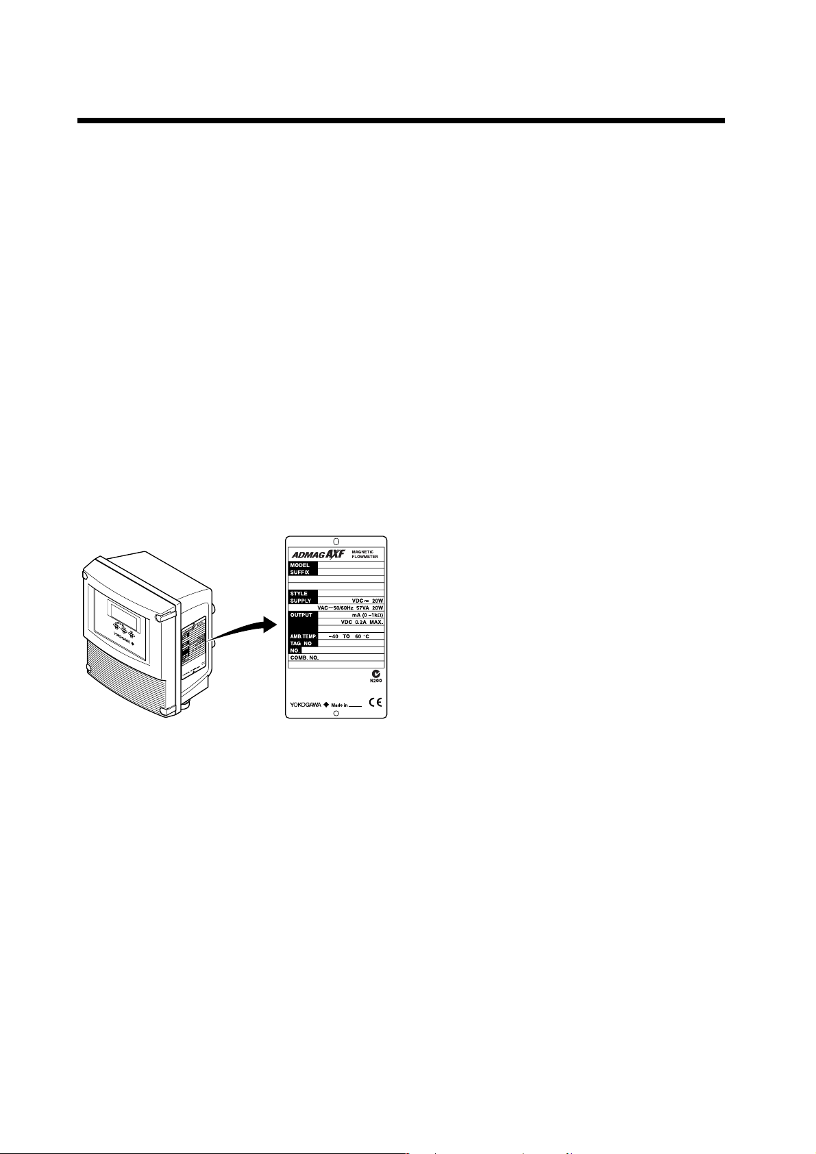
2.1 Checking Model and
Specifications
The model code and specifications are found on the
data plate located on the outside of the case. Check
that the model code and specifications match what you
have ordered.
Be sure you have your model number and serial
number available when contacting Yokogawa.
2.3 Storage Precautions
If the instrument is to be stored for a long period of
time after delivery, observe the following points.
The instrument should be stored in its original
packing condition in the storage location.
Select a storage location that fulfils the following
conditions:
• A place where it will not be exposed to rain or
water
• A place subject to minimal vibrations or shocks
• Temperature and humidity levels should be as
follows:
Temperature: -30 to 70°C
Humidity: 5 to 80% RH (no condensation)
The preferred ambient temperature and
humidity levels are 25°C and approximately
65% RH.
If the AXFA11 is transferred to the installation site
and stored without being installed, its performance
may be impaired due to the infiltration of rainwater
and so forth. Be sure to install and wire the
AXFA11 as soon as possible after transferring it to
the installation location.
F0201.EPS
2.2 Accessories
Check that the parts shown below are included in the
package:
Mounting hardware: 1 set
2.4 Installation Location
Precautions
Select the installation location with consideration to the
following items to ensure long-term stable operation of
the instrument.
Ambient Temperature:
Avoid installing the instrument in locations with
constantly fluctuating temperatures. If the location is
subject to radiant heat from the plant, provide heat
insulation or improve ventilation.
Atmospheric Condition:
Avoid installing the instrument in a corrosive
atmosphere. In situations where this is unavoidable,
consider ways to improve ventilation and to prevent
rainwater from entering and being retained in the
conduit pipes.
Vibrations or Shocks:
Avoid installing the instrument in a place subject to
shocks or vibrations.
2-1
IM 01E20C01-01E
3. INSTALLATION
3. INSTALLATION
WARNING
Installation of the magnetic flowmeter must be performed by expert engineer or skilled personnel. No
operator shall be permitted to perform procedures relating to installation.
3.1 Installation Location
IMPORTANT
Install the instrument in a location where it is not exposed to direct sunlight. For ambient temperature,
refer to Chapter 11 “OUTLINE”.
The instrument may be used in an ambient humidity where the RH ranges from 0 to 100%. However,
avoid long-term continuous operation at relative humidity above 95%.
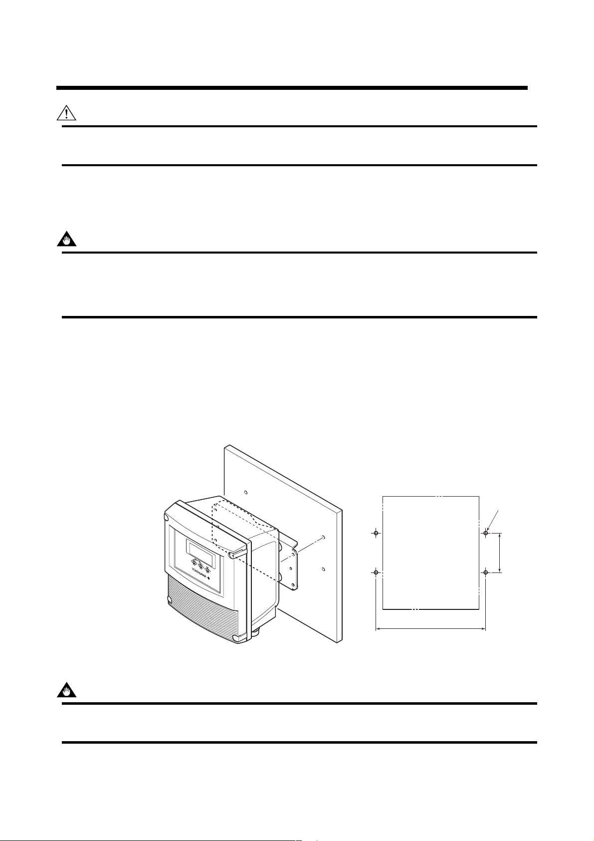
3.2 Mounting
This instrument can be mounted using surface mounting, 2-inch pipe mounting, or panel
mounting.
Surface Mounting (Wall Mounting)
Unit: mm
(approx. inch)
For surface mounting, use the mounting
fixture provided, using M6 screws.
These M6 screws must be provided
by the user.
194 (7.64)
4-6 Hole or
M6 Screw
65
(2.56)
F0301.EPS
Figure 3.2.1 Surface Mounting
IMPORTANT
Mounting fixture on equipment intended to be mounted on a wall or ceiling shall withstand a force of four
times the weight of the equipment (AXFA11: 3.3kg (7.3 lb)).
3-1
IM 01E20C01-01E
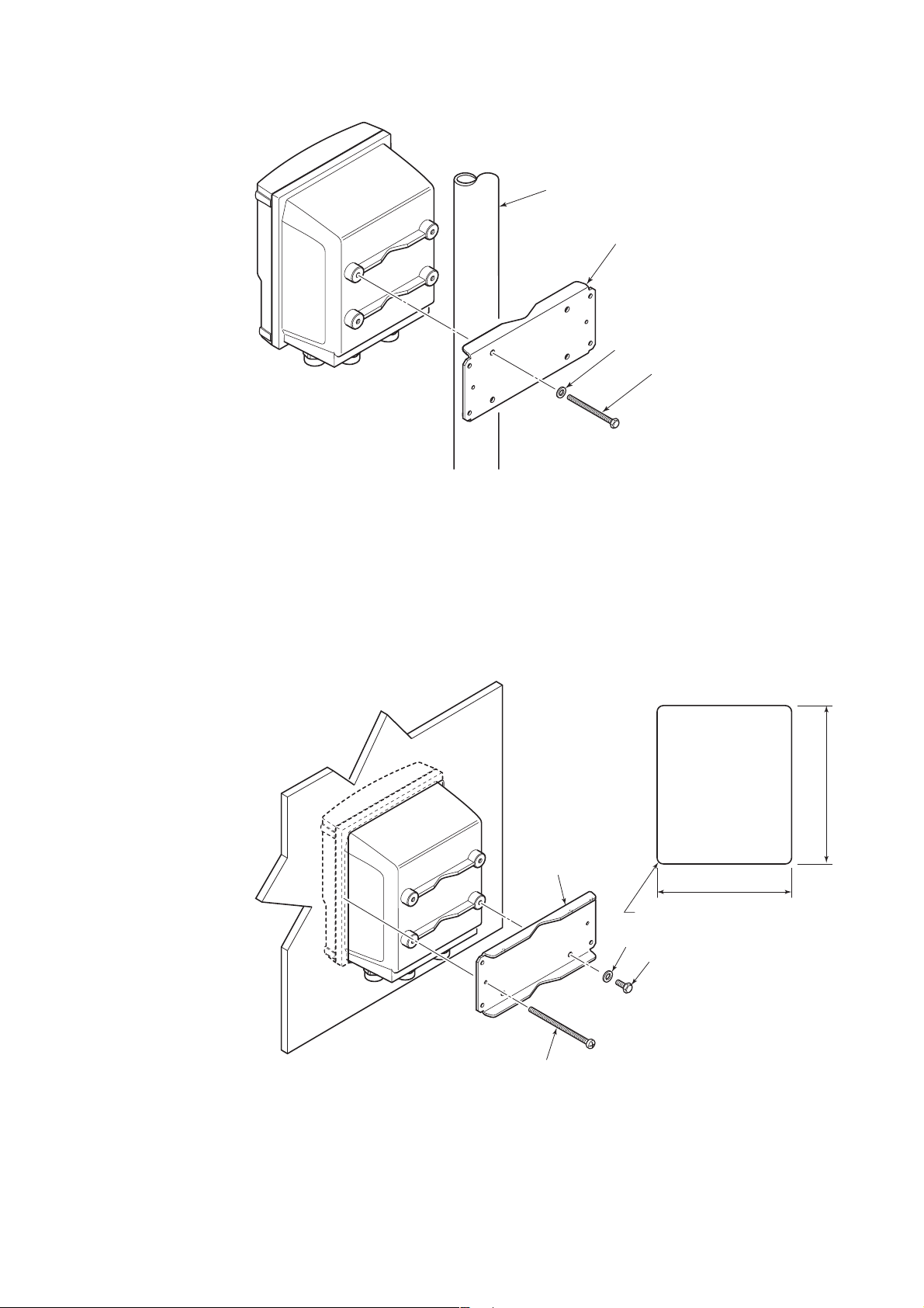
2-inch Pipe Mounting
2-inch pipe
Mounting fixture
Washer
Clamp screw
Pass the four clamp screws through the mounting fixture, position it on the 2-inch pipe,
and then fasten the AXFA11 in place.
3. INSTALLATION
Figure 3.2.2 2-inch Pipe Mounting
Panel Mounting
F0302.EPS
Unit: mm
(approx. inch)
Panel cutout
203 (8.0)
Mounting fixture
172 (6.8)
R3MAX
Washer
Screw
Fit the AXFA11 into the panel. Then attach the mounting fixture to the AXFA11 using the screw and the
washer, and secure the instrument with the two clamp screws.
Figure 3.2.3 Panel Mounting
3-2
Clamp screw
F0303.EPS
IM 01E20C01-01E
4. WIRING
4. WIRING
This section describes the wiring on the converter side
only. For information relating to wiring on the
flowtube side, refer to the user’s manual of the AXF
Remote Flowtube (IM 01E20D01-01E).
WARNING
The wiring of the magnetic flowmeter must be
performed by expert engineer or skilled personnel. No operator shall be permitted to perform
procedures relating to wiring.
CAUTION
Once all wiring is complete, check the connections before applying power to the instrument.
Improper arrangements or wiring may cause a
unit malfunction or damage.
4.1 Wiring Precautions
Be sure to observe the following precautions when
wiring:
four-core cables are used for wiring. Keep
conduits or flexible tubes watertight using
sealing tape.
• Ground the remote flowtube and the converter
separately.
• Cover each shield of the signal cable with vinyl
tube or vinyl tape to avoid contact between two
shields or between a shield and a case.
• When waterproof glands or union equipped
waterproof glands are used, avoid tightening
the glands with an excessive torque.
• Be sure to turn power off before opening the
cover.
• Before turning the power on, tighten the cover
securely.
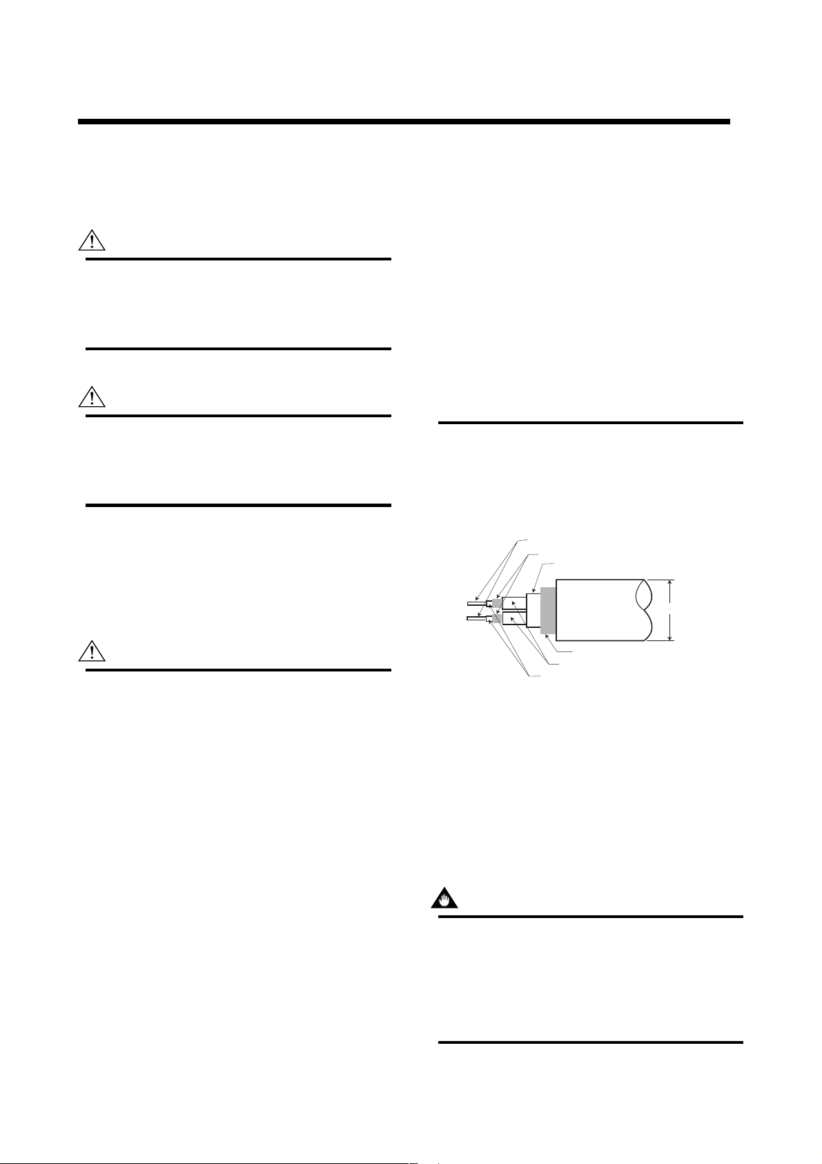
4.2 Cables
(1) Dedicated Signal Cable (AXFC)
Conductors (A and B)
Shields (SA and SB)
Tape
Outer jacket
10.5 (0.413″)
CAUTION
• In cases where the ambient temperature
exceeds 50°C (122°F), use external heatresistant wiring with a maximum allowable
temperature of 70°C (158°F) or above.
• Do not connect cables outdoors in wet weather
in order to prevent damage from condensation
and to protect the insulation.
• Do not splice the cable between the flowtube
terminal and the converter if it is too short.
Replace the short cable with a cable that is the
appropriate length.
• All the cable ends must be provided with round
crimp-on terminals and be securely wired.
• The signal cables must be routed in separate
steel conduit tubes 16 (JIS C 8305) or flexible
conduit tubes 15 (JIS C 8309).
• Always route the power and output signal
cables in separate steel conduit tubes, except
when the power supply voltage is 24 V and
Shield (C)
Insulation
Insulation
Figure 4.2.1 Dedicated Signal Cable AXFC
F0401.EPS
The flow signal is transmitted via this dedicated cable.
The cable is constructed with double shielding over the
two conductors, and heat-resistant vinyl is used for the
outer jacket material.
Finished diameter: 10.5 mm (0.413″)
Maximum length: 200 m (660 ft)
Maximum temperature: 80°C (176°F)
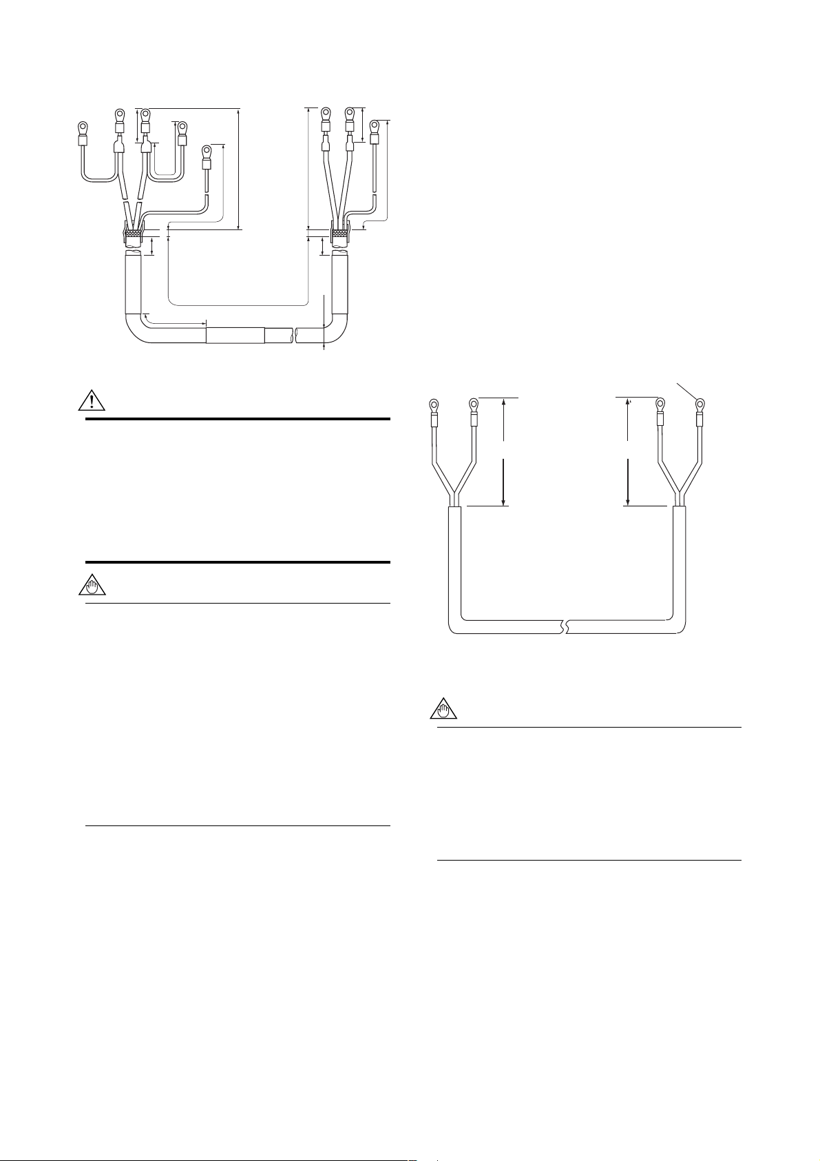
IMPORTANT
If the cable is longer than required, cut off any
extra length rather than coiling it up, and terminate the conductors as shown in Figure 4.2.2.
Avoid using junction terminal boards to extend
the cable length, as this will interrupt the shielding.
4-1
IM 01E20C01-01E
4. WIRING
Unit : mm
(approx. inch)
ACB
SA
White Black
On the
converter
side
25 (0.98)
5
150
8(0.3) max.
(5.9)
20 (0.8)
SB
50 (1.97)
Red
60 (2.36)
70 (2.76)
L (Specified Dimensions)
AXFC
ACB
55 (2.17)
90 (3.54)
White Black Red
8 (0.3) max.
5
On the
(5.9)
150
flowtube
side
10.5 (0.4)
F0402.EPS
Figure 4.2.2 Treatment of Dedicated Signal Cables
CAUTION
• As crimp terminals A, B, SA, SB and C have
their own electrical potentials, securely insulate
them so as not to come in contact with one
another.
• To prevent a shield from coming in contact with
another shield or the case, cover each shield
with a vinyl tube or wrap it in vinyl tape.
90 (3.54)
With gland options EG, EU and EW;
• Excitation cable;
10.5 or 11.5 mm (0.41 or 0.45 in.)
• Power and output cable;
7.5 to 12 mm (0.30 to 0.47 in.)
With gland options EP;
6 to 12 mm (0.24 to 0.47 in.)
Nominal Cross Section:
Single wire; 0.5 to 2.5 mm
Stranded wire; 0.5 to 1.5 mm
2
2
In case of power cable, Green/Yellow covered conductor shall be used only for connection to PROTECTIVE
CONDUCTOR TERMINALS. Conform to IEC227,
IEC245 or equivalent national authorization.
Unit : mm
(approx. inch)
Crimp Terminal
EX2
EX1
85 (3.35)
On the converter side
85 (3.35)
On the flowtube side
EX1
EX2
NOTE
Conductors A and B carry the signal from the
electrodes, and C is at the potential of the liquid
(signal common). Shields SA and SB are kept
at the same potentials as the individual electrodes (these are actively driven shields.) This is
done to reduce the effect of the distributed
capacitance of the cable at long cable length.
Note that, since the signals from the individual
electrodes are impedance converted inside the
converter, errors will result if they come in
contact with any other component. Great care
must be taken in the cable end treatment.
(2) Excitation Cable/Power Cable/Output
Cable
JIS C3401 control cable equivalent
JIS C3312 power cable equivalent
14 AWG Belden 8720 equivalent
Outer Diameter:
With no gland option;
6.5 to 12 mm (0.26 to 0.47 in.)
F0403.EPS
Figure 4.2.3 End Treatment of Excitation Cable
• For excitation and power cables, always use a
crimp terminal with an insulation cover.
• Use crimp tools from the manufacturer of the
crimp terminal you want to use to connect the
crimp terminal and cable.
• Use crimp tools that are appropriate for the
diameter of the cable to be connected.
4-2
IM 01E20C01-01E

4. WIRING
4.3 Wiring Ports
This instrument is of watertight construction as
stipulated in JIS C0920. It is shipped with a wiring
bracket (waterproof gland or waterproof gland with
union) or a plastic gland attached, only in cases where
an optional specification is selected for the wiring port.
IMPORTANT
The wiring port is sealed with a cap (not waterproof). Do not remove the cap from the unused
wiring port. If waterproof property is necessary,
please use waterproof glands.
(1) When waterproof property is unnecessary
(When there are no particular optional
specifications)
The wiring port is sealed with a cap (not water-proof)
that must be removed before wiring. At this time,
handle the wiring port in accordance with the JIS
C0920 mentioned above. Do not remove the cap from
the unused wiring port.
For working on the electric wire tubes or the flexible
tubes (PF1/2), remove the waterproof gland and attach
them directly to the wiring port.
Washer
PF1/2
Gasket
Tightening gland
Cable
When working on conduit pipes or flexible pipes (PF1/2 only)
F0405.EPS
Figure 4.3.2 Waterproof Gland with Union Joint
(Optional Code EU)
(2) When waterproof property is necessary
(Wiring using waterproof glands)
IMPORTANT
To prevent water or condensation from entering
the converter housing, waterproof glands are
recommended. Do not over-tighten the glands or
damage to the cables may result. Tightness of
the gland can be checked by confirming that the
cable is held firmly in place.
Washer
Gasket
Waterproof gland
Cable
F0404.EPS
Plastic gland
Figure 4.3.3 Plastic Gland (Optional Code EP)
PF1/2
PF3/4
Extension plug (x2)
Conversion plug (x5)
Cable
When working on electric wire tube or flexible tube (PF3/4)
* When connecting PF1/2, remove the conversion plug and
connect directly to wiring port.
Figure 4.3.4 PF3/4 Waterproof Gland (Optional Code EW)
F0406.EPS
Gasket
Washer
Figure 4.3.1 Waterproof Gland (Optional Code EG)
4-3
IM 01E20C01-01E
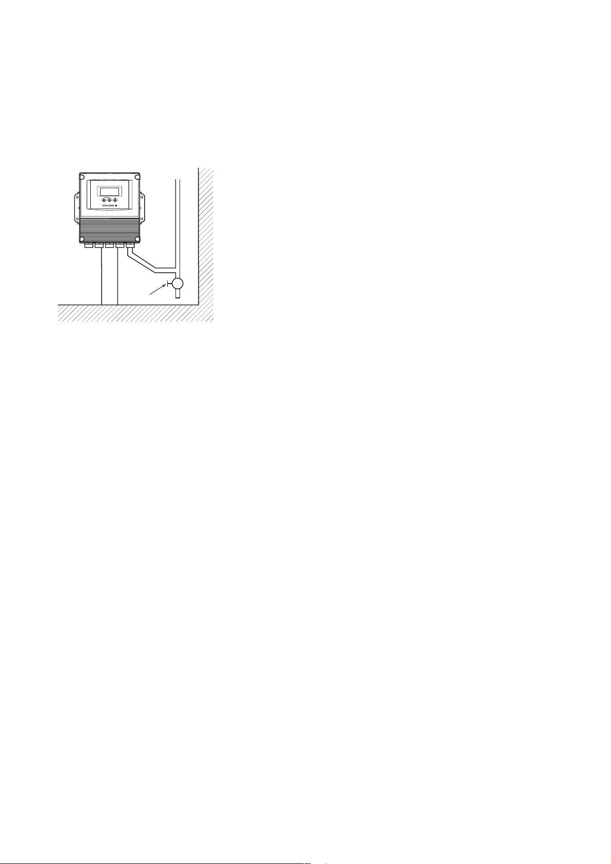
(3) Conduit Wiring
When wiring the conduits, pass the conduit through the
wiring connection port, and utilize the waterproof
gland to prevent water from flowing in. Place the
conduit pipe on an angle as shown in Figure 4.3.5.
Install a drain valve at the low end of the vertical pipe,
and open the valve regularly.
Drain valve
F0408.EPS
Figure 4.3.5 Conduit Wiring
4. WIRING
4-4
IM 01E20C01-01E
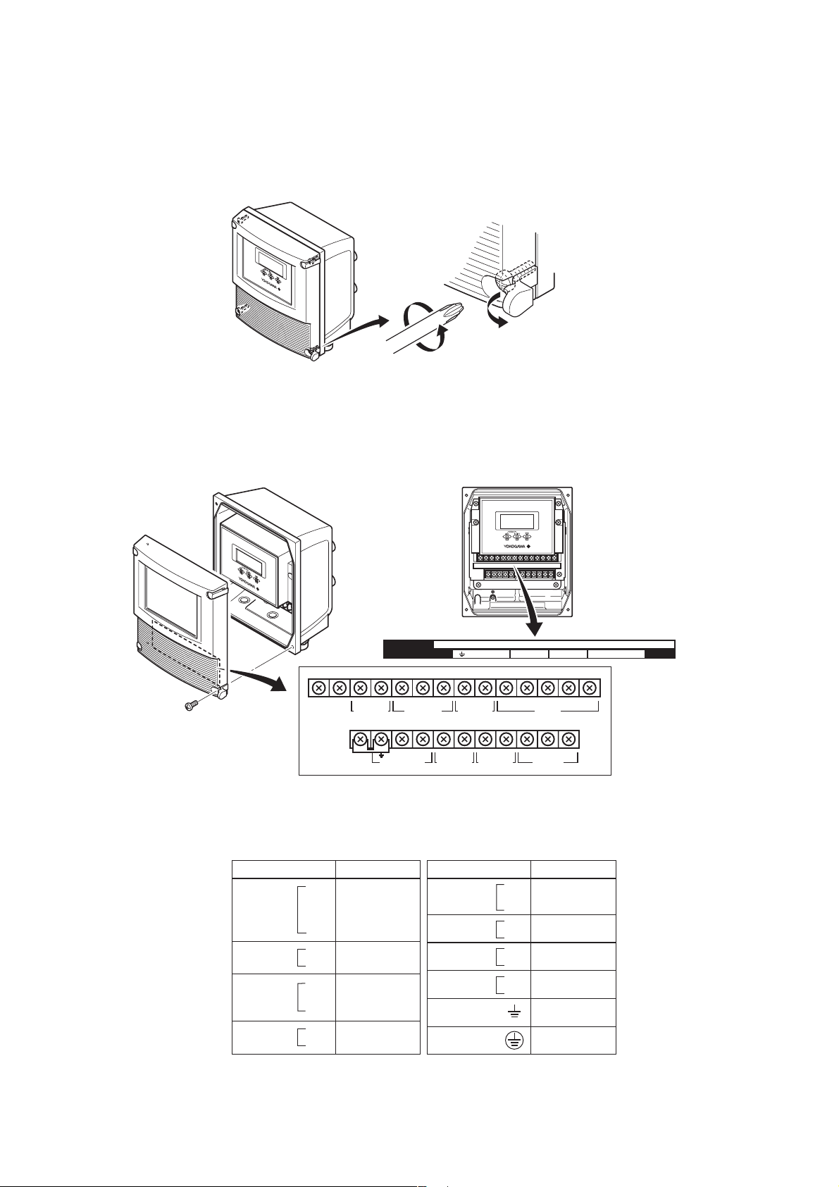
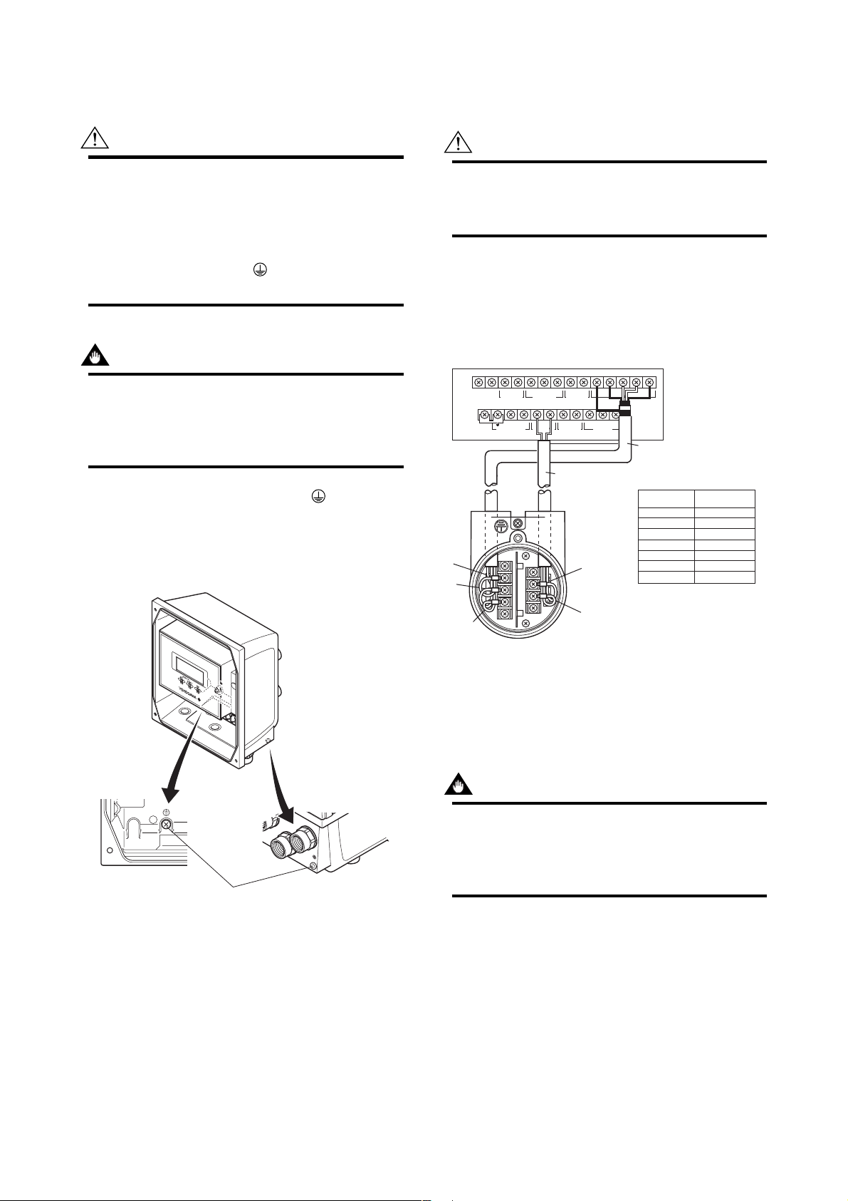
4.4 Wiring Connections
4.4.1 Removing Cover
While supporting the front of the cover with your hand, flip the connecting screw protective cover over, and remove the four connecting screws.
Figure 4.4.1 Removing the Front Cover
4.4.2 Terminal Configuration
When the cover is removed, the connection terminals will be visible. The terminal configuration labels are attached in the position shown in Figure 4.4.2.
4. WIRING
F0409.EPS
SO2+
N/– L/+ EX2EX1 P– SI1+ SI2+ COMP+
AL+ AL– C SA A B SB
ALARM OUT
EX2EX1
PULSE OUT STATUS IN
SIGNAL
P– SI1+ SI2+ COMP+
I+ I–
CURRENT OUT
POWER SUPPLY
SO1+ COMSO2+
STATUS OUT
N/– L/+
I+ I– AL+ AL– C SA A B SBSO1+ COM
EXCIT ATION
Figure 4.4.2 Terminal Layout Labels Position
The description of the terminal symbols is shown in Table 4.4.1.
Table 4.4.1 Terminal Symbols
Terminal Symbols
SIGNAL
ALARM OUT
STATUS OUT
CURRENT OUT
C
SA
A
B
SB
AL+
AL-
SO1+
SO2+
COM
I+
I-
Description
Flow signal input
Alarm output
Status output
(Two output)
Current output
4 to 20mA DC
Terminal Symbols
STATUS IN
PULSE OUT
EXCITATION
POWER SUPPLY
Description
Sl1+
Status input
Sl2+
(Two input)
COM
P+
Pulse output
P-
Excitation current
EX1
EX2
output
L /+
Power supply
N/-
Functional grounding
Protective grounding
(Outside of the terminal)
T0401.EPS
F0410.EPS
4-5
IM 01E20C01-01E

4. WIRING
IMPORTANT
Do not wire the terminal without terminal symbols in terminal layout labels.
4.4.3 Precautions for Wiring of Power
Supply Cables
When connecting to the power supply, observe the
points below. Failure to comply with these warnings
may result in an electric shock or damage to the
instrument.
WARNING
• Ensure that the power supply is OFF in order to
prevent electric shocks.
• Ensure the protective grounding terminal is
grounded before turning the power on.
• Use insulating sleeve crimp terminals (for 4-mm
screws) for the power supply wiring and protective grounding wiring.
• To prevent electric shocks, ensure the electrical
wiring cover (transparent) is attached.
• Install an external switch or circuit breaker as a
means to turn the powe off (capacitance; 15A,
conforming to IEC947-1 and IEC947-3). Locate
this switch either near the instrument or in other
places facilitating easy operation. Affix a
“Power Off Equipment” label to this external
switch or circuit breaker.
4.4.4 DC Power Connection
When using DC power as the power supply for the
converter, give attention to the following points.
(1) Connecting Power Supply
IMPORTANT
Do not connect power supply with reversed
polarities.
L/+ terminal: connect +
N/– terminal: connect
IMPORTANT
Do not connect power supply with 100 to 240 V
AC or 100 to 120 V DC in the case of a 24 V
power supply version (power supply code 2).
It will give a damage to the converter.
(2) Required Power Supply Voltages
IMPORTANT
When using a 24 V power supply, the specification for the supply voltage is 24 V (–15% to
+20%), but the input voltage of the converter
drops due to cable resistance therefore it must
be used within the following ranges.
Supply Voltage and Cable Length
–
Wiring Procedure
1. Turn the instrument’s power off, and remove the
wiring cover (transparent).
2. Wire the power supply cable and the functional
grounding cable to the power supply terminals.
CUR OUT STATUS OUT ALARM OUT SIGNAL
Functional
grounding cable
Figure 4.4.3 Electric Cable Wiring
POWER SUPPLY EXCITER
P–P+
PULSE OUT STATUS IN
Power supply cable
SBBASACAL–AL+COMSO2+SO1+I+ I–
COMSI2+SI1+EX2EX1L/+N/–
F0411.EPS
3. Reattach the electrical wiring cover (transparent).
420 (1380)
280 ( 920)
200 ( 660)
100 ( 330)
Allowable cable length m(ft)
0
20.4 22 24 26 28.8
Usable range E (V)
Cable cross section area: 1.25 mm
Cable cross section area: 2 mm
(3) Setting Power Supply Frequency
IMPORTANT
Set the local commercial power frequency in
order to eliminate the effect of induction noise
from the commercial power supply.
Refer to “Chapter 6: Parameter Description” in
this manual. Parameter No. J30 and J31.
4-6
2
2
F0411-2.EPS
IM 01E20C01-01E
4. WIRING
4.4.5 Grounding
CAUTION
Be sure to connect the protective grounding of
the AXFA11 with a cable of 2mm2 or larger cross
section in oder to avoid electrical shock to the
operators and maintenance engineers and to
prevent the influence of external noise. Connect
the grounding wire to the mark (100 or
less).
IMPORTANT
When optional code A (lighting protector) is
selected, the ground should satisfy Class C
requirements (grounding resistance, 10 or
less).
• The protective grounding terminals are located
on the inside and outside of the terminal area.
Either terminal may be used.
• Use 600 V vinyl insulation wires as the grounding
wires.
4.4.6 Wiring the Remote Flowtube
with the AXFA11 Converter
WARNING
Before wiring, be sure that the power supply for
AXFA11 converter has been turned off to
prevent an electrical shock.
(1) Connection with the Remote Flowtube
(General-Purpose Use, Submersible Type,
Sanitary Type, Size 2.5 to 400 mm (0.1 to
16 in.))
Connect wiring as shown in the figure below.
I+ I–
CURRENT OUT
N/– L/+
POWER SUPPLY
A
B
C
Figure 4.4.5 Wiring Diagram
AL+ AL– C SA A B SB
SO1+ COMSO2+
ALARM OUT
STATUS OUT
EX2EX1
P– SI1+ SI2+ COMP+
EXCIT ATION
PULSE OUT STATUS IN
Excitation cable
Remote flowtube
EX2
EX1
SIGNAL
AXFA11 Converter
AXFC Dedicated signal
cable
Converter
SA
A
B
SB
C
EX1
EX2
* Individually tape and insulate the
shields corresponding to SA and
SB on the remote flowtube side.
Remote
flowtube
Taping*
A
B
Taping*
C
EX1
EX2
F0415.EPS
Protective grounding terminals
F0414.EPS
Figure 4.4.4 Protective Grounding Terminal Location
(2) Connection with the Remote Flowtube
(Explosion proof Type, Size 2.5 to 400 mm
(0.1 to 16 in.))
IMPORTANT
In case of TIIS Flame proof type, a remote
flowtube cannot be combined with AXFA11
converter. In this case, use the AXFA14 converter.
4-7
IM 01E20C01-01E

4. WIRING
In case of explosion proof type for ATEX, FM, and
CSA certification, connect wiring as shown in the
figure below.
In case of the explosion proof type, the protective
grounding
of remote flowtube must be connected to
a suitable IS grounding system. In that case,
(functional grounding terminal) need not be connected.
I+ I–
CURRENT OUT
N/– L/+
POWER SUPPLY
A
B
C
Figure 4.4.6 Wiring Diagram
AL+ AL– C SA A B SB
SO1+ COMSO2+
ALARM OUT
STATUS OUT
EX2EX1
P– SI1+ SI2+ COMP+
EXCIT ATION
PULSE OUT STATUS IN
Excitation cable
Remote flowtube
EX2
EX1
SIGNAL
AXFA11 Converter
AXFC Dedicated signal
cable
Converter
SA
A
B
SB
C
EX1
EX2
* Individually tape and insulate the
shields corresponding to SA and
SB on the remote flowtube side.
Remote
flowtube
Taping*
A
B
Taping*
C
EX1
EX2
F0416.EPS
(4) Connection with the Remote Flowtube
(General-Purpose Use, Submersible Type,
Size 1100 to 2600 mm (44 to 104 in.))
Connect wiring as shown in the figure below.
SO1+ COMSO2+
I+
Shortbar
CURRENT OUT
4-20mA out
N/– L/+
POWER SUPPLY
I–
AL+ AL– C SA A B SB
STATUS OUT
ALARM OUT
EX2EX1
P– SI1+ SI2+ COMP+
EXCIT ATION
PULSE OUT STATUS IN
SIGNAL
AXFA11 converter
AXFC dedicated
signal cable
Excitation
cable
A
EX2
B
C
EX1
Converter
SA
A
B
SB
C
EX1
EX2
* Individually tape and insulate
the shields corresponding to SA
and SB on the remote flowtube
side.
Remote flowtube
Remote
flowtube
Taping*
A
B
Taping*
C
EX1
EX2
F040218.EPS
Figure 4.4.8 Wiring Diagram
4.4.7 Connecting to External Instruments
(3) Connection with the Remote Flowtube
(General-Purpose Use, Submersible Type,
Size 500 to 1000 mm (20 to 40 in.))
Connect wiring as shown in the figure below.
SO1+ COMSO2+
I+
I–
CURRENT OUT
4-20mA out
N/– L/+
POWER SUPPLY
Shortbar
A
B
C
Figure 4.4.7 Wiring Diagram
AL+ AL– C SA A B SB
STATUS OUT
ALARM OUT
EX2EX1
P– SI1+ SI2+ COMP+
EXCIT ATION
PULSE OUT STATUS IN
Excitation
cable
EX2
EX1
Remote flowtube
SIGNAL
AXFA11 converter
AXFC dedicated
signal cable
Converter
SA
A
B
SB
C
EX1
EX2
* Individually tape and insulate
the shields corresponding to SA
and SB on the remote flowtube
side.
Remote
flowtube
Taping*
Taping*
EX1
EX2
F040217.EPS
WARNING
Before wiring with external instrument, be sure to
turn off the power supply for AXFA11 converter
and any external instruments.
Connect the AXFA11 terminal to external instruments,
giving attention to the following points.
4 to 20 mA DC Current Output
A
B
C
AXFA11
l+
Receiver
l-
Instrument
Resistive Load Max. 1 kΩ.
(When using BRAIN/ HART communication,
more than 250 Ω, less than 600 Ω).
Figure 4.4.9 4 to 20 mA DC Output Connection
F0417.EPS
4-8
IM 01E20C01-01E
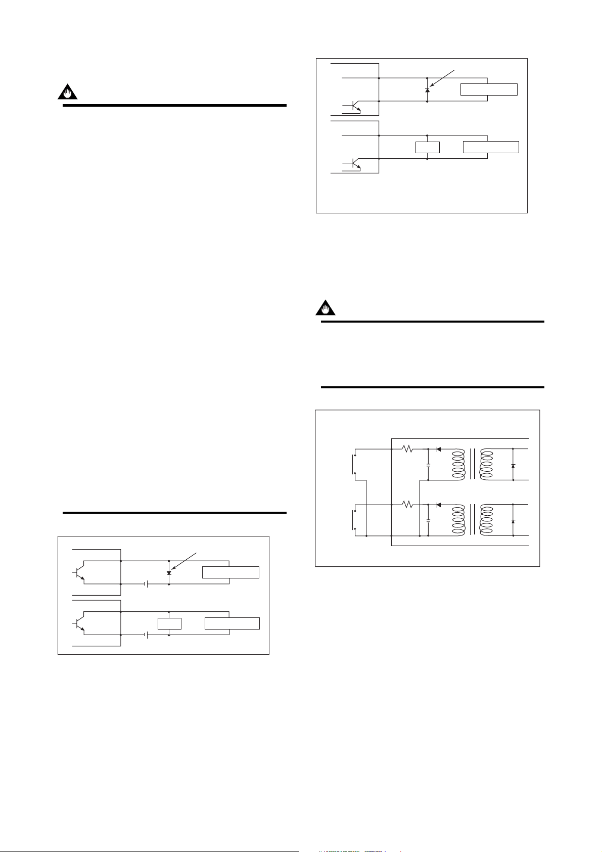
4. WIRING
Pulse Output
IMPORTANT
• As this is a transistor contact (insulated type),
give attention to proper voltage and polarity
when wiring.
• Do not apply a voltage larger than 30V DC or a
current larger than 0.2A in order to prevent
damage to the instrument.
• When input filter constant of the electronic
counter is large in relation to the pulse width,
the signal will decrease and the count will not
be accurate.
• If the input impedance of the electronic counter
is large, an induction noise from the power
supply may result in inaccurate counts. Use a
shield cable or sufficiently reduce the input
impedance of the electronic counter within the
electromagnetic flowmeter pulse output specification range.
• The active pulse output (Optional Code EM)
cannot be used in conjunction with the standard
pulse output.
• When the active pulse output (Optional Code
EM) is selected, do not be short-circuit between
the P+ and P– terminals to avoid damaging the
instrument.
• When the active pulse output (Optional code
EM) is selected, the range of pulse rate must
be set to 2 pps maximum.
• To avoid communication (BRAIN/ HART)
failure, it is recommended to use the shield
cable.
AXFA11
PULSE OUT
AXFA11
PULSE OUT
Output voltage: 24 V DC 20%
• Current: 150 mA or less
Pulse rate: 0.0001 to 2 pps
Pulse width: 20, 33, 50, 100 ms
Figure 4.4.11 Active Pulse Output Connection
P+
P-
P+
P-
(Optional code EM)
Load
Protective diode
Mechanical Counter
Electronic Counter
F0419.EPS
Status Input
IMPORTANT
Status inputs are designed for use with novoltage (dry) contacts. Be careful not to connect
the status to any signal source carrying voltage.
Applying voltage may damage the input circuit.
Closed: Less than 200 Ω
Open: More than 100 kΩ
+
SI1
+
SI2
AXFA11
AXFA11
PULSE OUT
AXFA11
PULSE OUT
Figure 4.4.10 Pulse Output Connection
P+
P-
P+
P-
Load
30V DC, 0.2A. max
Protective diode
Mechanical Counter
Electronic Counter
F0418.EPS
COM
No-voltage status input
Figure 4.4.12 Status Input Connection
4-9
F0420.EPS
IM 01E20C01-01E
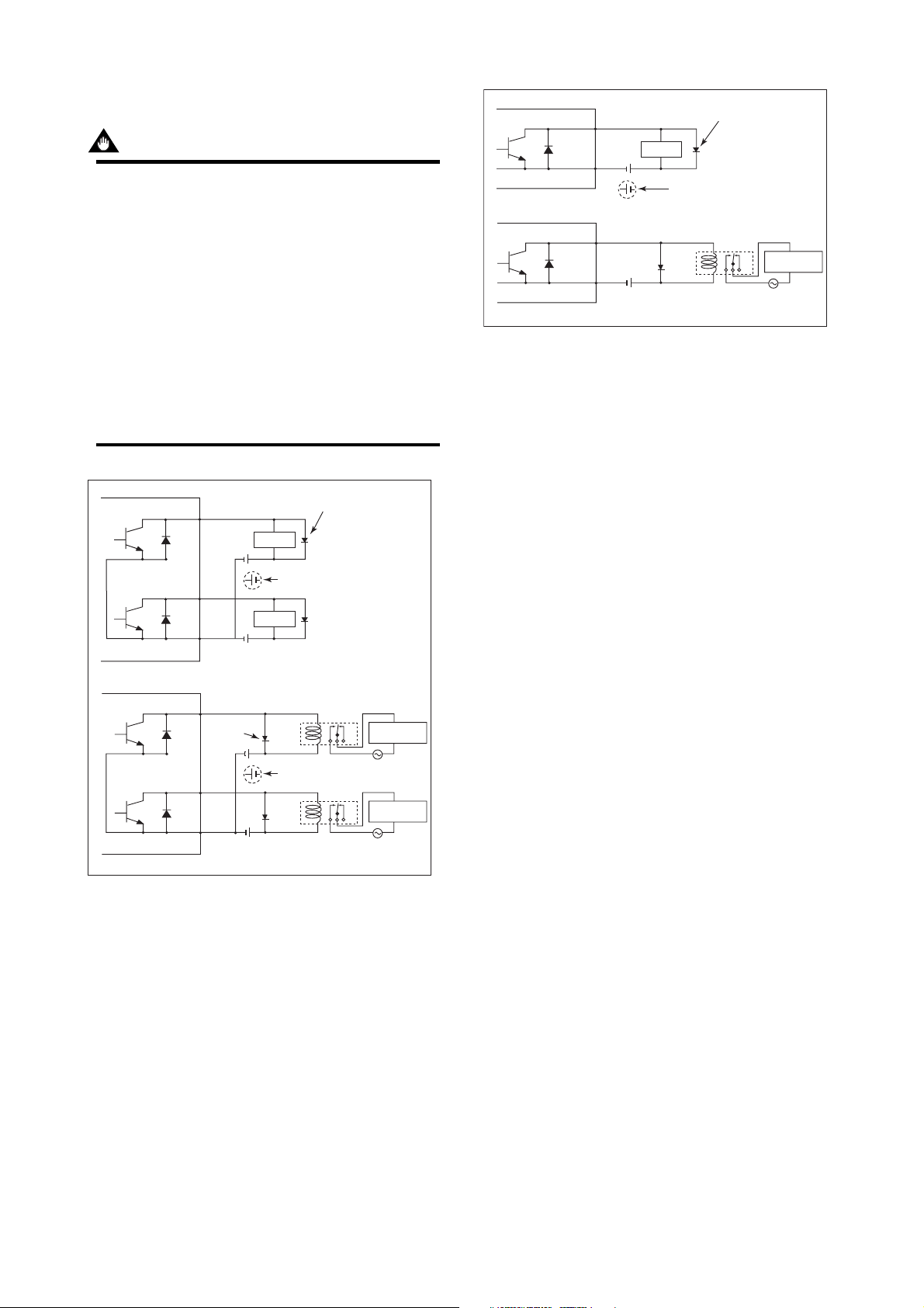
Status Output / Alarm Output
IMPORTANT
Since this is an isolated transistor output, be
careful of voltage and polarity when wiring.
Do not apply a voltage larger than 30V DC or a
current larger than 0.2A in order to prevent
damage to the instrument.
This output cannot switch an AC load. To switch
an AC load, an intermediate relay must be
inserted as shown in Figure 4.4.13 or Figure
4.4.14.
*The alarm output operates from closed (normal)
to open (alarm occurrence) in the default value
(as setup upon plant shipment). Changes can
be made via the parameter settings.
AXFA11
AXFA11
+
AL
Load
—
AL
This connection is not possible.
+
AL
—
AL
External power supply
30V DC, 0.2A. max
Figure 4.4.14 Alarm Output Connection
4. WIRING
Protective diode
Relay
Electromagnetic
AC power supply
valve
F0422.EPS
AXFA11
+
SO1
Load
This connection is not possible.
Load
This connection is not possible.
AXFA11
+
SO2
COM
External power supply
30V DC, 0.2A. max
+
SO1
Protective
diode
+
SO2
COM
External power supply
30V DC, 0.2A. max
Figure 4.4.13 Status Output Connection
Protective diode
Relay
Electromagnetic
Electromagnetic
AC power supply
valve
valve
F0421.EPS
4-10
IM 01E20C01-01E

5. BASIC OPERATING PROCEDURES
5.
BASIC OPERATING PROCEDURES
The modification of data settings from the display unit can be carried out using the three
setting switches (infra-red switches) — namely, the , , and switches.
The infra-red switches enable the user to set parameters without opening the cover.
This chapter will provide a description of basic data configuration and the methods to be
used with the three setting switches. The AXFA11 can also be operated using a handheld
Brain Terminal (BT200) or a HART Communicator. (Please refer to Chapter 7 for operation via Brain Terminal and Chapter 8 for operation via HART Communicator.)
WARNING
Be sure to set parameters as «Protect» on the write protect function after finish of
parameter setting work.
Under extremely rare case, the infra-red switches may respond unexpectedly in
such conditions as sticking ball of water or extraneous substances on the surface
of display panel glass according to the principle of infra-red switch operation.
Its probability rises in such cases as sticking rain water by storm or other similar
situation and washing up work near flowmeter installation place.
Either to illuminate or stop illuminating the infra-red switches by the flashlight may
cause the mis-reaction.
Refer to Chapter 6 «Menu P: Parameter Protection Items» and section «10.2.3»
how to use the write protect function in detail.
(USING THE DISPLAY UNIT)
IMPORTANT
Operate the display unit under the condition where direct sunlight, etc… do not shine
to the setting switches directly when the parameter setting operation is carried out.
NOTE
(1) Always use the setting switches with the cover of the AXFA11 closed.
(2) Use these switches with them covered by the glass window.
(3) If dirt, dust or other substances surfaces on the display panel glass, wipe
them clean with a soft dry cloth.
(4) The operation with dirty gloves may cause a switch response error.
5-1
IM 01E20C01-01E
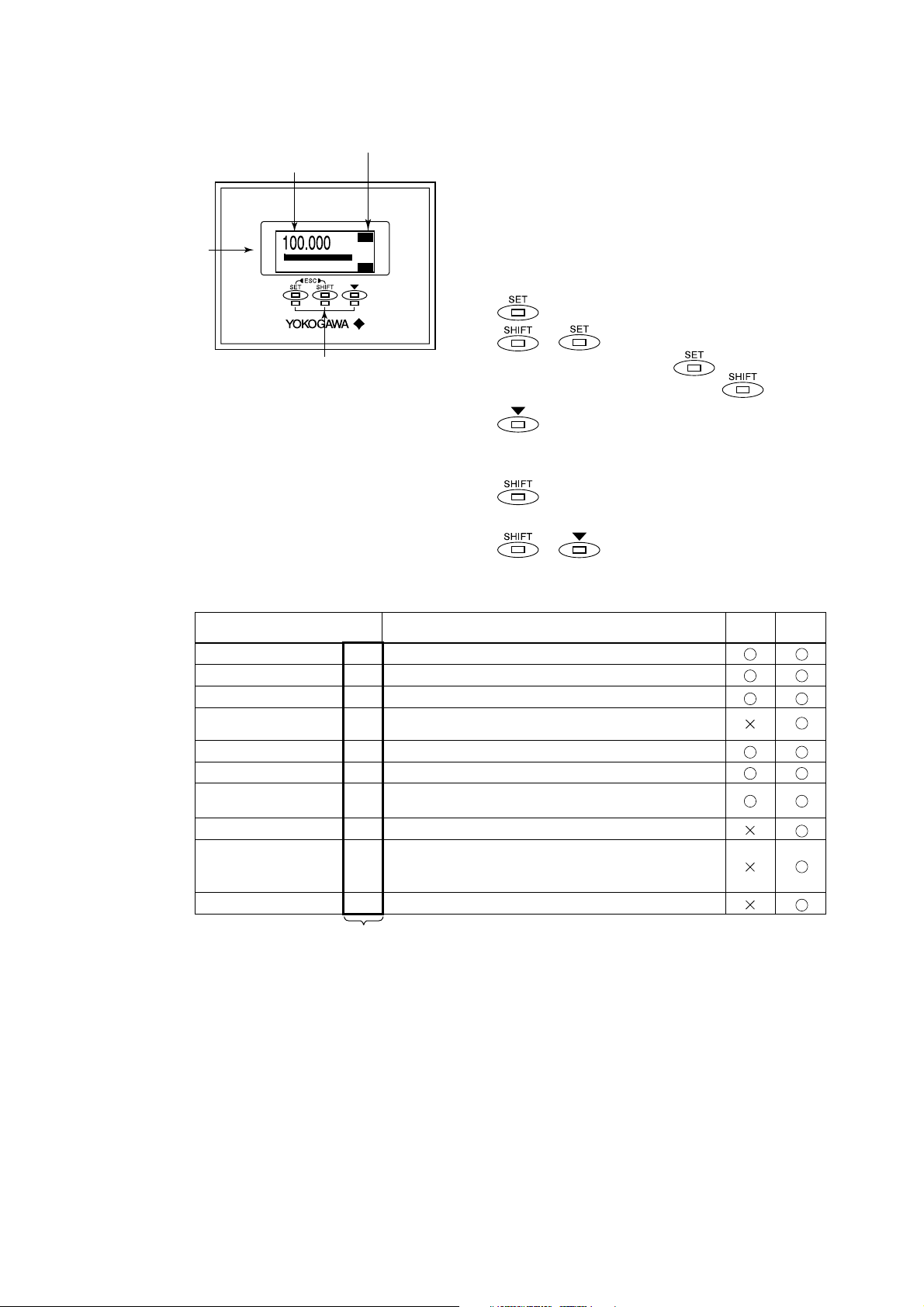
5. BASIC OPERATING PROCEDURES
5.1 Operating Panel Configuration and Functions
(4)
(3) Display items
Reversed character display
(1) Data display area
: : :
0
(2) Setting switches
(Infra-red switches)
3274m
3
3
/h
m
100
FTL
FR
F0501.EPS
(1) Data display area
1st line (Display Select1), 2nd line (Display
Select2), and 3rd line (Display Select3) can be
displayed using parameter settings. The content
corresponding to selected item is shown with the
reversed-character on the right of the line.
(2) Setting switch operations
: Move the layer down, select, and confirm
+ : Move the layer up
(Press the switch while
holding down the switch)
: Move the cursor down (for selection-type
parameters) or increase values (for numeric-type parameters)
: Move the cursor to the right (for numeric-
type parameters)
(3) Display items
Displayed items and
reversed-character indication
Instantaneous flow rate: %
Actual instantaneous flow rate
Instantaneous flow rate: mA
Bar graph indicating
instantaneous flow rate
Totalized forward-direction flow rate
Totalized reverse-direction flow rate
Totalized differential flow rate
Tag number
Diagnosis of electrode adhesion
Communication type
+ : Move the cursor up (for selec-
tion-type parameters)
Content
Displays the instantaneous flow rate for the span as a percentage.
FR
Displays the actual reading for instantaneous flow rate.
FR
Displays the instantaneous flow rate for the span as a current output value.
FR
Displays the instantaneous flow rate for the span as a percentage
None
using bar graph.
Displays the totalized value for flow rate in the forward direction.
FTL
Displays the totalized value for flow rate in the reverse direction.
RTL
Displays the differential totalized value for flow rate between
DTL
forward totalization and reverse totalization.
Display the tag number (using up to 16 characters).
TA G
Displays the adhesion condition in the form of a bar graph.
ADH
(See the description for parameters K10 through K15 from
Chapter 6: Parameter Description for more details.)
Displays the communication type.
COM
(4)
Disp Select1
Disp Select2
Disp Select3
T0501.EPS
5-2
IM 01E20C01-01E
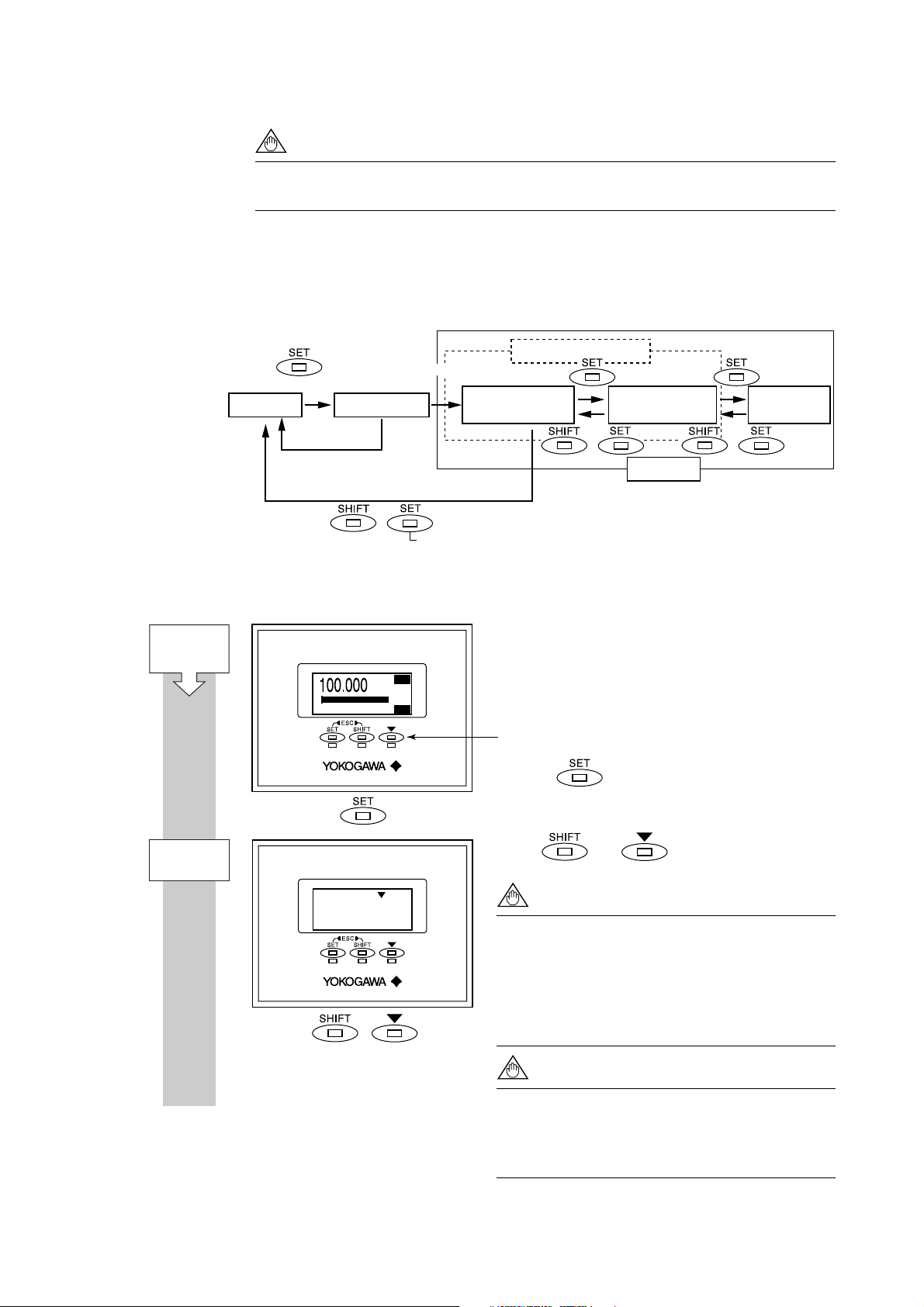
5.2 Display Unit Setting Methods
NOTE
Before changing any settings, be sure to check the corresponding setting details
in Chapter 6: Parameter Description.
5.2.1 Display Mode → Setting Mode
Display Mode will be adopted when the power is turned on, and the Setting Mode can be
activated using the following procedure.
Parameter Search Mode
(2 seconds or more)
Display Mode
Entry Mode
Select “Yes”
Major Item Parameter
Search Mode
5. BASIC OPERATING PROCEDURES
Sub-item Parameter
Search Mode
Parameter
Replacement Mode
Start:
Display Mode
(*1)
Entry Mode
Select “No”
* The term «mode» is used to refer to a situation
where display and setting are possible.
+
Press the SET switch while holding down the SHIFT switch.
+ +
Setting modes
F0502.EPS
Sample Display: Procedure for moving from Display Mode to Setting Mode
1st line: Actual instantaneous flow rate [FR]
2nd line: Bar graph indicating instantaneous flow
rate
3rd line: Totalized forward flow rate [FTL]
Setting switches
: : :
0
3274m
m
3
FTL
FR
3
/h
100
Hold the switch for 2 seconds.
Touch and switches simultaneously.
Touch SHIFT + key
NOTE
F0503-1.EPS
When other operations are carried out, the
system will automatically return to the Display
Mode.
When no operations in this display are carried
out for 20 seconds, the system will automatically return to the Display Mode.
(*1)
NOTE
The Major Item Parameter which is set just
before will be shown when entrying the Setting
Mode again within 1 minute after returning
from Setting Mode to Display Mode.
5-3
IM 01E20C01-01E
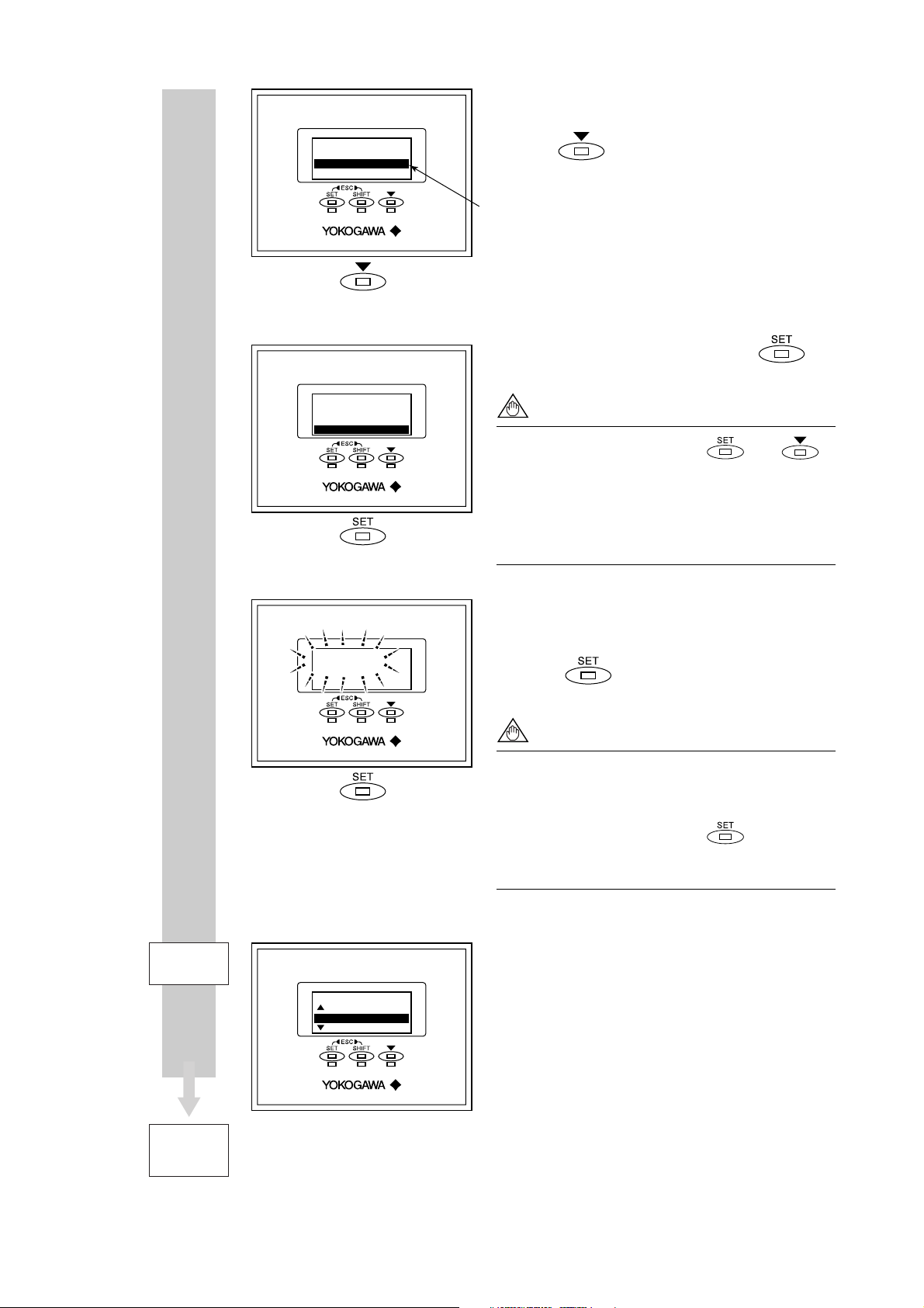
Setting Mode
No
Yes
Setting Mode
No
Yes
5. BASIC OPERATING PROCEDURES
A screen is displayed to confirm whether or not the
system is to enter Setting Mode.
Press the
The reversed-character (i.e. the cursor position)
indicates the item that is currently selected.
switch and select [Yes].
When [Yes] has been selected, touch the
switch.
NOTE
When the operations except and
switches are carried out, the system will
automatically return to the Display Mode.
When no operations in this display are carried
out for 20 seconds, the system will automatically return to the Display Mode.
Setting Mode
Setting Mode
Yes
Setting Mode
P:Protect
B:Easy Setup
C:Basic Setup
In order to request confirmation, the entire display
flashes on and off.
Touch the switch once again at this time to
fix your selection.
NOTE
When no operations in the flashed display are
carried out for 20 seconds, the system will
automatically return to the Display Mode.
When the operations except are carried
out, the system will automatically return to the
Display Mode.
The system enters Setting Mode.
Parameters to be set can be selected.
To Parameter
Search Mode
F0503-2.EPS
This completes the procedure for changing from the
Display Mode to the Parameter Search Mode.
5-4
IM 01E20C01-01E

5.2.2 Setting Mode
When the Setting Mode has been activated using the procedure from Section 5.2.1, parameters can be selected for setting.
Format for Parameter Data
Depending on the type of parameter, data is formatted in one of the following three ways.
5. BASIC OPERATING PROCEDURES
NOTE
If no operations are carried out for a period of 10 minutes in Setting Mode, the
system will automatically return to the Display Mode.
Format Typical display Content
(i) Selection-type
(ii) Numeric-type
(iii) Alphanumeric-type
Regarding the alphanumeric-type format (iii), the following alphanumerics are displayed in the following sequence:
#%&*+-./0123456789:<>ABCDEFGHIJKLMNOPQRSTUVWXYZabcdefghij
klmnopqrstuvwxyz[space]
B21:Base Flow Unit
3
m
3
m
kl(Kiloliter)
B23:Flow Span
100 l/min
000100 l/min
Rng:0.00001 32000
C10:Tag No
FI-1101
FI-1201
The desired data item is selected from a predefined list.
Data is set using the values in each digit and using
the decimal point.
Data is composed using alphanumeric characters
(in the case of tag numbers, special units, and the like).
With this format, setting can be carried out using up to
16 of the characters shown below.
T0502.EPS
5.3 Parameter Setting Procedure
Once the system is in Setting Mode, the parameters for setting can be selected. On the
AXFA11, parameters that are frequently used have been grouped together in Easy Setup in
Menu B. This section provides a description of the parameter setting procedure using B:
Easy Setup and C: Basic Setup.
For more details regarding parameter content, please refer to Section 6: Parameter Description.
5.3.1 Setting Example for Selection-Type Data: Flow rate units
This example describes the setting of the flow rate units for the selection-type parameter
B21: Base Flow Unit from m3 to l (Liter).
Start:
Major Item
Parameter
Search Mode
Setting Mode
Major item
parameter
Setting Mode
P:Protect
B:Easy Setup
C:Basic Setup
F0504-1.EPS
Major Item Parameter Search Mode has been
accessed in this screen.
Touch the switch to access B: Easy Setup.
NOTE
The and symbols to the left of the param-
eters indicate that additional setting items to
those being currently displayed may also be
selected. Use the switch to cycle
through these items.
5-5
IM 01E20C01-01E

5. BASIC OPERATING PROCEDURES
Sub-item
Parameter
Search Mode
Parameter
Replacement Mode
Current unit setting
Available selections
Current unit setting
Available selections
Major item
Sub-item
parameter
Major item
Sub-item
selection (A)
Sub-item
Sub-item
B:Easy Setup
50:Auto Zero Exe
10:Language
20:Flow Damping
B:Easy Setup
20:Flow Damping
21:Base Flow Unit
22:Base Time Unit
B21:Base Flow Unit
3
m
3
m
kl(Kiloliter)
B21:Base Flow Unit
3
m
l(Liter)
3
cm
Sub-item Parameter Search Mode has been accessed
in this screen.
Touch the
X
2
B21: Base Flow Unit.
switch to move the cursor to
The cursor has been moved to B21: Base Flow
Unit in this screen. (Sub-item selection screen (A))
In this screen, Parameter Replacement Mode has
been called up using the switch.
Touch the switch to move the cursor to the
unit item for selection. In this example, the
switch is touched twice to select l (Liter)
X
2
B21:Base Flow Unit
l(Liter)
When l (Liter) has been selected, touch the
switch.
In order to request confirmation, the entire display
flashes on and off.
Touch the switch once again at this time to
fix your selection.
NOTE
When no operations are carried out for 20
seconds in the flashing state, the system will
automatically return to the Sub-item Parameter
Search Mode.
When the operations except are carried
out, the parameter cannot be set.
Sub-item
Parameter
Search Mode
Major item
Sub-item
selection (A)
B:Easy Setup
20:Flow Damping
21:Base Flow Unit
22:Base Time Unit
F0504-2.EPS
The system returns automatically to sub-item
selection screen (A).
5-6
IM 01E20C01-01E

5. BASIC OPERATING PROCEDURES
5.3.2 Setting Example for Numeric-Type Data: Flow rate span
This example describes the setting of the flow rate span for the numeric-type parameter
B23: Flow Span from 100 l/min to 120 l/min.
Start:
Major Item
Parameter
Search Mode
Sub-item
Parameter
Search Mode
Setting mode
Major item
parameter
Major item
Sub-item
parameter
Major item
Sub-item
selection (B)
Setting Mode
P:Protect
B:Easy Setup
C:Basic Setup
B:Easy Setup
50:Auto Zero Exe
10:Language
20:Flow Damping
X
4
B:Easy Setup
22:Base Time Unit
23:Flow Span
24:Flow Decimal Pnt
Selection of the appropriate parameter
Setting Mode Condition
Touch the switch to access B: Easy Setup.
NOTE
The and symbols to the left of the
parameters indicate that additional setting
items to those being currently displayed may
also be selected. Use the
switch to
cycle through these items.
Sub-item Parameter Search Mode has been accessed
in this screen.
Touch the switch to move the cursor to
B23: Flow Span.
The cursor has been moved to B23: Flow Span in
this screen. (Sub-item selection screen (B))
Touch the switch to access Parameter
Replacement Mode.
Parameter
Replacement Mode
B23:Flow Span
100 l/min
000100. l/min
Rng:0.00001 32000
B23:Flow Span
100 l/min
0000100. l/min
Rng:0.00001
32000
X
X
F0505-1.EPS
4
2
Once Parameter Replacement Mode has been
selected, the digit that can be replaced will be flashed
on and off. When in this condition, confirm the
relevant setting range as displayed at the bottom of
the screen and then set the parameter as required.
In this example, the parameter will be set to “120 l/
min”.
NOTE
When setting a new value, use the switch
to move from digit to digit, and use the
switch to cycle through values for each individual digit. In addition to digit, it is also possible
to select a decimal point, and this allows the
position of the decimal point to be changed.
Modify the value to “120 l/min” as follows:
Touch the switch to move the cursor to the
position for multiples of 10. Then, touch the
switch to change the value at this position from “0” to
“2”. When the value of “120” has been setup, touch
the switch.
5-7
IM 01E20C01-01E
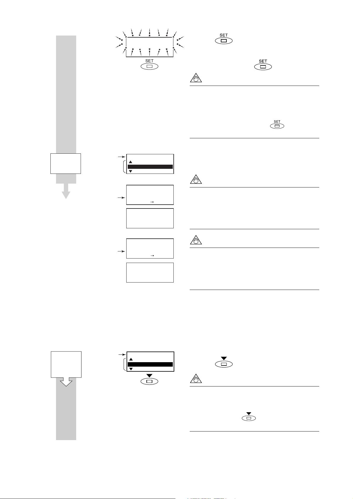
5. BASIC OPERATING PROCEDURES
Sub-item
Parameter
Search Mode
Major item
Sub-item
selection (B)
Incorrect setting:
B23:Flow Span
120 l/min
B:Easy Setup
22:Base Time Unit
23:Flow Span
24:Flow Decimal Pnt
B23:Flow Span
100 l/min
1200000 l/min
Rng:0.00001 32000
Out of range.
Touch any key.
When the switch is touched, the entire
display flashes on and off. Confirm that the setting
has been correctly changed to “120”, and then fix
this value by touching the switch once again.
NOTE
When no operations are carried out for 20
seconds in the flashing state, the system will
automatically return to the Sub-item Parameter
Search Mode.
When the operations except are carried
out, the parameter cannot be set.
The system automatically returns to sub-item
selection screen (B).
NOTE
If the input value is outside the valid selection
range, the message “Out of range. Touch any
key.” will be displayed. In such a case, touch
any switch to return to Parameter Replacement
Mode and redo the setting.
Incorrect setting:
B23:Flow Span
100 l/min
0001.0. l/min
Rng:0.00001
Invalid value.
Touch any key.
32000
NOTE
If more than one decimal point has been input,
the message “Invalid value. Touch any key.”
will be displayed. In such a case, touch any
switch to return to Parameter Replacement
F0505-2.EPS
Mode and redo the setting.
5.3.3 Setting Example for Alphanumeric-Type Data: Tag number
This example describes the setting of the tag number for the alphanumeric-type parameter
C10: Tag No. from “FI-1101” to “FI-1201.”
Start:
Major Item
Parameter
Search Mode
Setting mode
Major item
parameter
Setting Mode
P:Protect
B:Easy Setup
C:Basic Setup
F0506-1.EPS
Setting Mode Condition
Touch the switch to access C: Basic Setup.
NOTE
The and symbols to the left of the parameters indicate that additional setting items to
those being currently displayed may also be
selected. Use the switch to cycle through
these items.
5-8
IM 01E20C01-01E
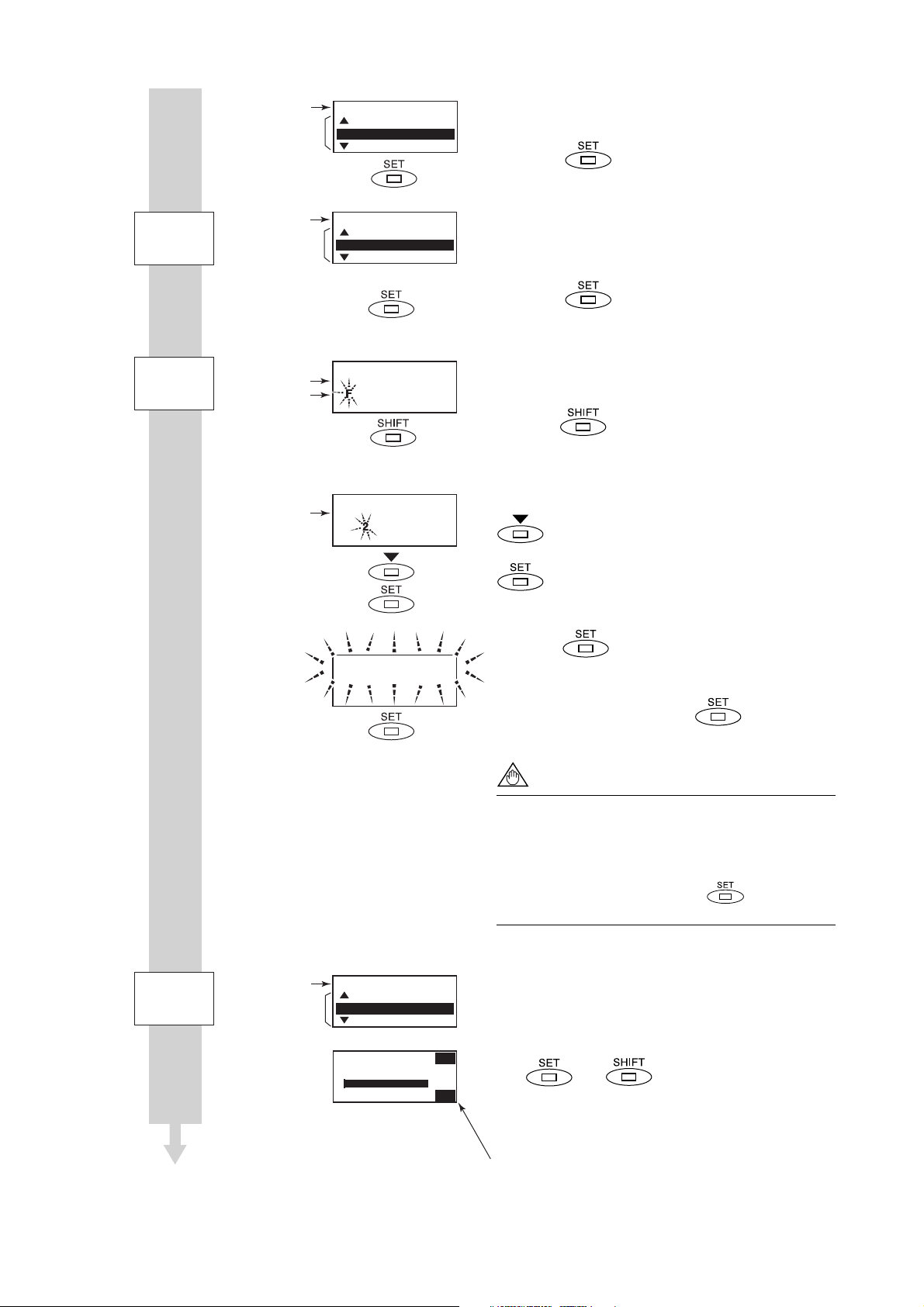
5. BASIC OPERATING PROCEDURES
Sub-item
Parameter
Search Mode
Parameter
Replacement Mode
Current setting value
Modified value
Current setting value
Setting mode
Major item
parameter
Major item
Sub-item
selection (C)
Setting Mode
B:Easy Setup
C:Basic Setup
D:Total Set
C:Basic Setup
49:Flow User Span
10:Tag No
11:Flow Damping
Selection of the appropriate parameter
C10:Tag No
Fl-1101
l-1101
X
4
C10:Tag No
Fl-1101
Fl-1 01
The cursor has been moved to C: Basic Setup in
this screen.
Touch the
switch to enter C: Basic Setup.
Upon selection of C: Basic Setup, the cursor will
be positioned at C10: Tag No. (Sub-item selection
screen (C))
Touch the switch to access Parameter
Replacement Mode.
The cursor will flash on and off on the left of the tag
number. As “FI-1201” is to be setup in this example,
touch the switch to move the cursor to the
position for multiples of 100.
At the position for multiples of 100, touch the
switch to change the “1” to “2”. When the
setting has been changed to “FI-1201”, touch the
switch.
Sub-item
Parameter
Search Mode
Major item
Sub-item
selection (C)
C10:Tag No
Fl-1201
C:Basic Setup
49:Flow User Span
10:Tag No
11:Flow Damping
108.0
: : :
0
Fl-1201 TAG
FR
l/min
100
F0506-2.EPS
When the switch is touched, the entire
display flashes on and off. Confirm that the setting
has been correctly changed to “FI-1201”, and then
fix this setting by touching the switch once
again.
NOTE
When no operations are carried out for 20
seconds in the flashing state, the system will
automatically return to the Sub-item Parameter
Search Mode.
When the operations except are carried
out, the parameter cannot be set.
The system automatically returns to sub-item
selection screen (C).
After returning to Display Mode by touching using
the ( and ) twice as escape switches,
it will be possible to confirm the modified content (if
Display Select has been setup to display the tag
number.)
Indicates selection of Tag No display for B42: Display Select3.
5-9
IM 01E20C01-01E
6. PARAMETER DESCRIPTION
6. PARAMETER DESCRIPTION
6.1 Parameters
With the exception of parameters that were specified
by the customer upon ordering, all of the AXFA11’s
internal parameters will initially be set to default
values. Actions such as the modification of display
details can then be carried out whenever necessary.
IMPORTANT
Make sure to keep the AXFA11’s power on at
least for 30 seconds after you set the parameters. If you turn the power off immediately after
the parameters are set, the settings will be
canceled.
6.2 Parameter Lists
Parameter lists are comprised of the following items.
In order to ensure that correct flow rate data can
be acquired, it is crucial that the nominal size,
flow rate span, and meter factor of the combined
remote flowtube are setup. In cases where a
remote flowtube is ordered at the same time as
the AXFA11, the nominal size and meter factor
will be setup upon shipment from the manufacturing plant, and these will not require additional
setting. If the AXFA11 is ordered individually, the
default value will be setup for the meter factor;
accordingly, it will be necessary to change this
setting to the meter factor indicated on your
remote flowtube data plate.
If a flow rate span is specified upon ordering,
this will be set before shipment. If this is not the
case, however, it will be necessary for the
appropriate value to be set up by the user.
Item Name
R/W
Data
range
Units
Position of
decimal point
Default
value
Description
Describes the parameter content.
The default value (as setup upon plant shipment).
If marked “(*)”, it indicates that the appropriate
setting has been made in accordance with
ordering information and data for a remote
flowtube to be combined.
The position of the decimal point within the data
range and also the allowed relocation range in
terms of places of decimals.
The units corresponding to the data range.
This item defines the range of data to be set for
numeric parameters and also defines selection of
data for selection-type parameters.
R: Read only
W: Writable
The name of the parameter. Entries in parentheses
indicate the parameter name displayed on the
handheld BRAIN Terminal (BT200).
Parameter number.
T0601.EPS
6-1
IM 01E20C01-01E

6. PARAMETER DESCRIPTION
6.3 Parameter List Overview
(1) Item A (Menu A): Display items
Menu A contains the instantaneous flow rate, totalization values, and other items relevant to display.
Item
Display unit
(BRAIN)
A00
Display
(DISPLAY)
FR
A10
(FLOW RATE (%))
FR
A20
(FLOW RATE)
FR
A21
(FLW RATE (mA))
FTL
A30
(TOTAL)
RTL
A31
(REV TOTAL)
DTL
A32
(DIF TOTAL)
—
A60
(SELF CHECK)
Name
R/W
R
R
R
R
R
R
R
Data range
Display unit
/BRAIN
-110.0 to 110.0
-999999 to 999999
2.400 to 21.600
0 to 99999999
0 to 99999999
-99999999
to 99999999
Good
Error
Units
%
B21/B22
(C40/C41)
mA
B30
(D10)
B30
(D10)
B30
(D10)
Position
of decimal
point
1
0 to 3
3
0 to 7
0 to 7
0 to 7
Default value
(*): Indicated item
Description
For Display Mode only
For Display Mode only
For Display Mode only
For Display Mode only
For Display Mode only
For Display Mode only
See “6.5 Alarm Functions”.
T0602.EPS
(2) Item B (Menu B): Easy Setup items
Those parameters with a high frequency of use have been grouped together in Menu B. All basic functions can be
controlled using only the parameters from this block.
Name
Item
Display unit
(BRAIN)
B00 Easy Setup
(EASY SETUP)
B10 Language
(LANGUAGE)
B20 Flow Damping
(FLOW DAMPING)
B21 Base Flow Unit
(FLOW UNIT)
R/W
W English
W 0.1 to 200.0 s 1 3.0 s Sets damping time. Linked with
W Ml(Megaliter)
Data range
Display unit
/BRAIN
Japanese
French
German
Italian
Spanish
3
m
kl (Kiloliter)
l (Liter)
cm3
m
t
kg
g
kcf
cf
mcf
Mgal (US)
kgal (US)
gal (US)
mgal (US)
kbbl (US Oil)
bbl (US Oil)
mbbl (US Oil)
ubbl (US Oil)
kbbl (US Beer)
bbl (US Beer)
mbbl (US Beer)
ubbl (US Beer)
ft
klb (US)
lb (US)
Units
Position
of decimal
point
Default value
(*): Indicated item
English Selects the language used for the
display unit. Linked with H30.
C11.
m (*) Selects flow units for the flow
rate span. Linked with C40.
Description
T0603-1.EPS
6-2
IM 01E20C01-01E

6. PARAMETER DESCRIPTION
Name
Item
Display unit
(BRAIN)
B22 Base Time Unit
(TIME UNIT)
B23 Flow Span
(FLOW SPAN)
B24 Flow Decimal Pnt
(FLOW DECIMAL)
B30 Total Unit
(TOTAL UNIT)
B31 Total Scale
(TOTAL SCALE)
B32 Pulse Unit
(PULSE UNIT)
B33 Pulse Scale
(PULSE SCALE)
B40 Display Select1
(DISP SELECT1)
B41 Display Select2
(DISP SELECT2)
B42 Display Select3
(DISP SELECT3)
B50 Auto Zero Exe
(AUTOZERO EXE)
B60 —
(SELF CHECK)
Data range
R/W
Display unit
Units
/BRAIN
W/d
/h
/min
/s
W 0.0001 to 32000 B21
/B22
(C40/C41)
W Auto
0
1
2
3
Wn Unit/P
u Unit/P
m Unit/P
Unit/P
k Unit/P
M Unit/P
Pulse/s
W0 to 32000 B30
(D10)
Wn Unit/P
u Unit/P
m Unit/P
Unit/P
k Unit/P
M Unit/P
Pulse/s
W0 to 32000 B32
(E10)
W Flow Rate(%)
Flow Rate
Flow Rate(mA)
Forward Total
Reverse Total
Dif Total
W Off
Flow Rate(%)
Flow Rate
Flow Rate(mA)
Flow Rate(Bar)
Forward Total
Reverse Total
Dif Total
Tag No
Adhesion Check
Communication
W Same as B41
(Display Select2)
W No Execution
Execution
R Good
Error
Position
of decimal
point
Default value
(*): Indicated item
Description
/s (*) Selects time units for the flow
rate span. Linked with C41.
0 to 4 1 m/s (*) Sets flow rate span (with units
from B21 and B22). Linked with
C42.
Auto (*) Selects decimal point position
for the display unit’s
instantaneous flow rate. Linked
with C43.
Pulse/s (*) Selects the flow rate unit per one
pulse as used for totalization
display. Linked with D10.
0 to 4 0 (*) Sets the flow rate per one pulse
for the totalization display.
Linked with D11.
Pulse/s (*) Selects the flow rate unit per one
pulse as used for pulse output.
Linked with E10.
0 to 4 0 (*) Sets the flow rate per one pulse
as used for pulse output.
Linked with E11.
Flow Rate Selects content of the first line
for Display Mode. Linked with
H10.
Off Selects content of the second line
for Display Mode. Linked with
H11.
Off Selects content of the third line
for Display Mode. Linked with
H12.
No Execution Selects whether or not automatic
zero adjustment is carried out.
Linked with M10.
See “6.5 Alarm Functions”.
T0603-2.EPS
6-3
IM 01E20C01-01E

(3) Item C (Menu C): Basic Setting items
Menu C principally contains the basic setting items for the flowtube.
6. PARAMETER DESCRIPTION
Name
Item
Display unit
(BRAIN)
C00
Basic Setup
(BASIC SETUP)
C10
Tag No
(TAG NO)
C11 Flow Damping
(FLOW DAMPING)
C20 Measure Mode
(MEASURE MODE)
C21 Low MF
(LOW MF)
(HIGH MF)
(LOW MF(EDF))
(HIGH MF(EDF))
C30 Select Flow Tube
(FLOW TUBE)
C31 Nominal Size Unit
(SIZE UNIT)
(NOMINAL SIZE)
C40 Base Flow Unit
(FLOW UNIT)
C41 Base Time Unit
(TIME UNIT)
(FLOW SPAN)
C43 Flow Decimal Pnt
(FLOW DECIMAL)
R/W
Data range
Display unit
/BRAIN
ASCII 16 charactersW
Units
Position
of decimal
point
Default value
(*): Indicated item
Description
Sets Tag number up to 16
characters.
0.1 to 200.0Ws
143.0 s
Sets damping time. Linked with
B20.
Standard DF
W Standard DF
Enhanced DF
0.0100 to 3.0000W 1.0000 (*)
Selects measurement mode for
dual frequency excitation
Sets low-frequency meter factor for
standard dual frequency excitation
0.0100 to 3.0000W 1.0000 (*)
4C22 High MF
Sets high-frequency meter factor for
standard dual frequency excitation
0.0000 to 3.0000W 1.0000 (*)
4C23 Low MF(EDF)
Sets low-frequency meter factor for
enhanced dual frequency excitation
0.0000 to 3.0000W 1.0000 (*)
4C24 High MF(EDF)
Sets high-frequency meter factor for
enhanced dual frequency excitation
W
ADMAG AXF
ADMAG
ADMAG AE
ADMAG SE
ADMAG AXF
Selects the flowtube’s model
name.
Note: Select “ADMAG AXF” for
ADMAG AXW flowtube.
YEWMAG
Calibrator
Other
mm
Wmm
inch
0.99 to 3000.1
W 100 (*)
0.01 to 120.1
Wm (*)
Ml(Megaliter)
3
m
mm
inch
inch
0 to 2C32 Nominal Size
Selects the nominal size units for
the flowtube.
Sets flowtube nominal size in
selected unit at C31.
Selects flow units for the flow
rate span. Linked with B21.
kl(Kiloliter)
l(Liter)
3
cm
m
t
kg
g
kcf
cf
mcf
Mgal (US)
kgal (US)
gal (US)
mgal (US)
kbbl (US Oil)
bbl (US Oil)
mbbl (US Oil)
ubbl (US Oil)
kbbl (US Beer)
bbl (US Beer)
mbbl (US Beer)
ubbl (US Beer)
ft
klb (US)
lb (US)
/d
W /s (*)
/h
Selects time units for the flow
rate span. Linked with B22.
/min
/s
0.0001 to 32000W1 m/s (*)
C40/C41
(B21
/B22)
Auto
W Auto (*)
0
1
0 to 4C42 Flow Span
Sets flow rate span (with units
from C40 and C41). Linked with
B23.
Selects decimal point position for
the display unit’s instantaneous
flow rate. Linked with B24.
2
3
T0604-1.EPS
6-4
IM 01E20C01-01E

6. PARAMETER DESCRIPTION
Name
Item
Display unit
(BRAIN)
(VELOCITY CHK)
C45 Density Unit
(DENSITY UNIT)
R/W
W kg/m
Data range
Display unit
/BRAIN
0.000 to 99.999R
3
kg/m
lb/gal
Units
m/s 3C44 Velocity Check
Position
of decimal
point
Default value
(*): Indicated item
3
Description
Display of the span setting using
flow velocity (m/s).
Sets units for density when mass
flow rate is selected.
lb/cf
(MASS DENSITY)
C47 User Span Select
(USER SPN SEL)
C48 Flow User Unit
(FL USER UNIT)
(FL USER SPAN)
—
C60
(SELF CHECK)
0 to 32000W0
No
WNo
C45 0 to 4C46 Mass Flow Density
Yes
W
characters
0.0001 to 32000W 100
C48 0 to 4C49 Flow User Span
R
Error
Sets density when mass flow rate
is selected (with units from C45).
Selects whether or not special
units are used for flow rate units.
Sets the special flow rate units.8 alphanumeric
Sets span when using special flow
rate units.
See “6.5 Alarm Functions”.Good
T0604-2.EPS
(4) Item D (Menu D): Total Setting items
Menu D contains setting items such as the totalization scale and the forward/reverse totalized values.
Name
Item
Display unit
(BRAIN)
D00 Total Set
(TOTAL SET)
D10 Total Unit
(TOTAL UNIT)
D11 Total Scale
(TOTAL SCALE)
D12 Total Decimal Pnt
(TL DECIMAL)
D13 Total Low Cut
(TOTAL LOWCUT)
D20 Total Execution
(TOTAL EXEC)
D21 Ttl Set Val Lower
(TL SET VAL L)
D22 Ttl Set Val Upper
(TL SET VAL U)
D23 Ttl Switch Lower
(TL SWITCH LO)
D24 Ttl Switch Upper
(TL SWITCH UP)
D30 Ttl User Select
(TL USER SEL)
D31 Ttl User Unit
(TL USER UNIT)
D60 —
(SELF CHECK)
R/W
Wn Unit/P
W0 to 32000 D10
W0
W0 to 100 % 0 3 %
W Start
W0 to 999999 0 0
W0 to 99 0 0
W0 to 999999 0 0
W0 to 99 0 0
WNo
W8 alphanumeric
R Good
Data range
Display unit
/BRAIN
u Unit/P
m Unit/P
Unit/P
k Unit/P
M Unit/P
Pulse/s
1
2
3
4
5
6
7
Stop
Preset Total
Preset Rev Total
Yes
characters
Error
Units
(B30)
Position
of decimal
point
Default value
(*): Indicated item
Description
Pulse/s (*) Selects the flow rate unit per one
pulse as used for totalization
display. Linked with B30.
0 to 4 0 (*) Sets the flow rate per one pulse
for the totalization display.
Linked with B31.
0 Selects position of decimal point
for totalization display
Sets the range in vicinity of 0%
within which the totalization
display will be halted.
Start
Executes “Start” or “Stop” of the
totalization function, or executes
“Preset Total” or “Preset Rev
Total”.
Sets the totalization preset value
in the lower 6 digits of the 8-digit
totalized value.
Sets the totalization preset value
in the upper 2 digits of the 8-digit
totalized value.
Sets the totalization switch value
in the lower 6 digits of the 8-digit
totalized value.
Sets the totalization switch value
in the upper 2 digits of the 8digits totalized value.
No
Selects whether or not special
units are used as totalized units.
Sets the special totalized units.
See “6.5 Alarm Functions”.
6-5
T0605.EPS
IM 01E20C01-01E
 Loading…
|
Detail Specifications: 842/842153-admag_axf_series.pdf file (20 Apr 2023) |
Accompanying Data:
YOKOGAWA ADMAG AXF Series Measuring Instruments PDF Operation & User’s Manual (Updated: Thursday 20th of April 2023 03:59:34 PM)
Rating: 4.8 (rated by 97 users)
Compatible devices: EXA TB TB400G, BA11, SC72, WE430, 90020B, YS1000 Series, AQ6151B, ScopeCorder DL750.
Recommended Documentation:
Text Version of Operation & User’s Manual
(Ocr-Read Summary of Contents, UPD: 20 April 2023)
-
8, IM 01E20F02-01E 1-3 1. INTRODUCTION 1.2 Warranty • The warranty shall cover the period noted on the quotation presented to the purchaser at the time of purchase. Problems occurring during the warranty period shall basically be repaired free of charge. • If any problems are experienced with this instru- ment, the customer should contact the Yokogawa represe…
-
36, IM 01E20F02-01E 5-11 5. EXPLANATION OF BASIC ITEMS Alarm Display 1 0 0 . 1 2 l / h 3 2 3 4 5 6 M l1 IT2 F R C O Md a t i onF o u n d b u sF i e l scP r o e s r maA l p:3 1 E m i p ePt y llF i l f wu b eto w i t h if l u d 1 0 0 . 1 2 l / h 3 2 3 4 5 6 M l1 IT2 F R C O Md a t i onF o u n d b u sF i e l scP r o e s r maA l p:3 1 E m i p ePt y llF i l f wu b eto w i t h if l u d 1 0 0…
-
55, YOKOGAWA ADMAG AXF Series IM 01E20F02-01E 8-11 8. PARAMETER LISTS 8.4 Dl Function Block T0804-1.EPS Write Mode Explanation Factory Default Relative Index Parameter Name Index DI1 Index DI2 Information on this block such as Block Tag, DD Revision, Execution Time etc. The revision level of the static data of the DI block. The value of this parameter is incremented each time a static parameter value i…
-
33, YOKOGAWA ADMAG AXF Series IM 01E20F02-01E 5-8 5. EXPLANATION OF BASIC ITEMS 5.6 Integral LCD Indicator Employing 32*132 full dot matrix backlit LCD, various display can be obtained. 5.6.1 Flow Data Display By the transducer block parameters setting in DISPLAY_SELECT1, 2, 3 as described in 5.3, up to three lines display can be made among the following data. -Flow Rate(%) -Flow Rate -Flow Rate(Bar) -Integrator1 Out -Integr…
-
39, IM 01E20F02-01E 6-1 6. IN-PROCESS OPERATION 6. IN-PROCESS OPERATION This chapter describes the procedure performed when changing the operation of the function block of the AXF in process. 6.1 Mode Transition When the function block mode is changed to Out_Of_Service, the function block pauses and a block alarm is issued. When the function block mode is changed to Manual, the functio…
-
69, IM 01E20F02-01E A-10 APPENDIX 2. INTEGRATOR (IT) BLOCK Table A2.1 INTEG_TYPE Name Integration Method Integration Range Reset Trigger (Reset if one of the following conditions is established) Trip Output UP_AUTO(1) Counting up Starting from «0» -INF< Total <TOTAL_SP 0< ATotal <+INF 0< RTotal <+INF -INF< AccTotal <+INF • OUT reaches T…
-
45, IM 01E20F02-01E 8-1 8. PARAMETER LISTS 8. PARAMETER LISTS Note: The Write Mode column contains the modes in which each parameter is write enabled. O/S: Write enabled in O/S mode. MAN: Write enabled in Man mode and O/S mode. AUTO: Write enabled in Auto mode, Man mode, and O/S mode. 8.1 Resource Block T0801-1.EPS Write Mode Explanation Factory Default Relative Index Parameter Na…
-
2, YOKOGAWA ADMAG AXF Series i CONTENTS IM 01E20F02-01E 3rd Edition: June 2012 All Rights Reserved, Copyright © 2006, Yokogawa Electric Corporation CONTENTS 1. INTRODUCTION……………………………………………………………………………….. 1-1 Regarding This Manual ……………………………………………………………………… 1-1 1.1 Safe Use…
-
98, IM 01E20F02-01E A-39 APPENDIX 5. PID Block A5.17 Mode Shedding upon Computer Failure When the data status of RCAS_IN or ROUT_IN, which is the setting received from a computer as the setpoint SP, falls to Bad while the PID block is running in the RCas or ROut mode, the mode shedding occurs in accordance with the settings in SHED_OPT. If the RCAS_IN data is not renewed within …
-
66, IM 01E20F02-01E A-7 APPENDIX 2. INTEGRATOR (IT) BLOCK A2.2 Input Process Section When executed, the Integrator block first performs input processing in the order of: «Determining input status» → «Converting Rate or Accum» → «Determining the input flow direction» Switching between Convert Rate and Convert Accum is made using bit …
-
87, IM 01E20F02-01E A-28 APPENDIX 4. LINK MASTER FUNCTIONS 370 371 372 373 374 375 376 377 378 0 1 ChannelStatisticsSupported 2 MediumAndDataRatesSupported 3 IecVersion 4 NumOfChannels 5 PowerMode 0 1 channel-1 2 channel-2 3 channel-3 4 channel-4 5 channel-5 6 channel-6 7 channel-7 8 channel-8 0 1 InterfaceMode 2 LoopBackM…
Recommended Instructions:
HD12S, STR-DH130, GeForce GTX 560 FTW, AC Inverter


-
12V 7A12V 7AML931 / ML941 SET-UP GUIDESETTING UP YOUR MEDIASITE ML MULTIVIEW RECORDER1. CONNECT VIDEO SOURCE(S) ML931 A. Connect a 3G/HD/SD-SDI video source to an open SDI port. B. Connect an SD video source to the S-Video/Composite port. ML941 C. Connect an HDMI video source to the HDMI port. D. Connect a 3G/HD/SD-SDI video source to the SDI port. E. Connect an SD video …
ML931 2
-
Model 4200-CVU-PWR Parts Package PA-977 Rev. C / September 2016 *PPA-977C* 1 Keithley Instruments 28775 Aurora Road Cleveland, Ohio 44139 1-800-935-5595http://www.tek.com/keithleyIntroduction The Model 4200-CVU-PWR C-V Power Package for both the 4200A-SCS and 4200-SCS enables C-V measurements with a DC voltage bias of up to ±200 V or 400 V differential (0 …
KEITHLEY 4200-CVU-PWR 6
-
GREER COMPANYGREER COMPANYGREER COMPANYGREER COMPANY Crane SystemsCrane SystemsCrane SystemsCrane Systems GREER COMPANY 1918 East Glenwood Place, Santa Ana, CA 92705 Tel: 714) 259-9702 Fax: 714) 259-7626 PN W414107- MicroGuard 414 System Lattice Boom Cranes Horizontal Display Clyde M4190 Barge Mount OPERATOR’S MANUAL 12/20/01 1 of 21 MICROGUARDMIC …
Microguard 414 21
Additional Information:
Popular Right Now:
Operating Impressions, Questions and Answers:
![]()
![]()
Приборы измерения технологических параметров по ценам производителей
8 800 551 07 66
Бесплатный звонок
8 800 551 07 66
Бесплатный
звонок из любой точки России
8 831 218 05 61
Н. Новгород
Пн-Пт 8:00-17:00 Мск
Нижний Новгород,
ул. Невская, д. 19А
|
|
Серия электромагнитных расходомеров AXF представляет собой суперсовременный прибор, в котором сочетаются чрезвычайно высокая надежность и широкая функциональность, обеспечивающая простоту работы и обслуживания. В этой модели воплотился весь многолетний опыт по разработке и серийному выпуску электромагнитных расходомеров. Уникальная комбинация функции оценки загрязнения электрода и возможности снятия электрода без снятия расходомера с рабочей линии (заказывается как опция) делает этот электромагнитный расходомер гораздо более удобным для обслуживания на сложных позициях. Серия электромагнитных расходомеров AXF продолжает использовать уникальную методику двухчастотного возбуждения электромагнитным полем. Более того, в этой серии добавляется опция «Расширенного двухчастотного возбуждения», в которой высокая частота возбуждения еще выше. Тем самым вы получаете совершенный инструмент для измерения расхода на самых сложных «зашумленных» (с очень большим процентом механических включений) средах или на жидкостях с очень малой проводимостью (начиная от 1 мкС/см). Запросить цену
На Ваши вопросы ответит инженер-консультант Данил Артемьев d.artemiev@tehnonn.ru |
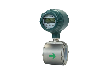
Технические характеристики
- Измеряемая среда: жидкость.
- Параметры измеряемой среды:
- минимальная электропроводность: от 1 мкСм/см;
- температура рабочей среды: -40… 180°С (уточняется при выборе футеровки);
- температура окружающей среды: -40…60°С;
- давление: от -0,1 до 4 МПа изб.;
- скорость потока: до 10 м/с.
- Условный проход трубопровода: 2,5…400 мм.
- Точность: стандартно ± 0,35% от показания, ± 0,2% от показания как опция.
- Выходы:
- от 3-х до 7-ми аналоговых 4…20мА и импульсных выходов в зависимости от модели ;
- цифровая связь (HART);
- индикатор: ЖК с подсветкой.
- Постоянная времени демпфирования: 0,1. ..200 с.
- Питание: 80…264 В/50 Гц или 24 В.
- Температура окружающей среды: -40…60°С
- Материалы, контактирующие с измеряемой средой:
- футеровка: полиуретан.тефлон,керамика, несколько видов резины;
- электроды: нерж. сталь, Hastelloy С, тантал, титан, платино-иридиевый сплав.
- Монтаж: фланцевый; бесфланцевый (типа «сэндвич»), санитарное исполнение
- Межповерочный интервал 5 лет.
Модели общего назначения/ погружного/ взрывозащищенного
типа:
| МОДЕЛЬ | DN (мм) (*1) | PS (МПа) (*1) | PS DN (МПа мм) | КАТЕГОРИЯ (*2) |
| AXF002G/C | 2,5 | 4 | 10 | Надлежащая инженернотехническая практика (*3) |
| AXF005G/C | 5 | 4 | 20 | Надлежащая инженернотехническая практика (*3) |
| AXF010G/C | 10 | 4 | 40 | Надлежащая инженернотехническая практика (*3) |
| AXF015G/W/C | 15 | 4 | 60 | Надлежащая инженернотехническая практика (*3) |
| AXF025G/W/C | 25 | 4 | 100 | Надлежащая инженернотехническая практика (*3) |
| AXF032G/W/C | 32 | 4 | 128 | II |
| AXF040G/W/C | 40 | 4 | 160 | II |
| AXF050G/W/C | 50 | 4 | 200 | II |
| AXF065G/W/C | 65 | 2 | 130 | II |
| AXF080G/W/C | 80 | 2 | 160 | II |
| AXF100G/W/C | 100 | 2 | 200 | II |
| AXF125G/W/C | 125 | 2 | 250 | II |
| AXF150G/W/C | 150 | 2 | 300 | II |
| AXF200G/W/C | 200 | 2 | 400 | III |
| AXF250G/W/C | 250 | 2 | 500 | III |
| AXF300G/W/C | 300 | 2 | 600 | III |
| AXF350G/W/C | 350 | 1 | 350 | II |
| AXF400G/W/C | 400 | 1 | 400 | III |