-
Contents
-
Table of Contents
-
Bookmarks
Quick Links
Test Equipment Depot — 800.517.8431 — 99 Washington Street Melrose, MA 02176 — TestEquipmentDepot.com
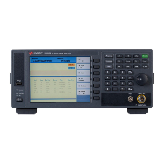
Agilent N9310A
RF Signal Generator
User’s Guide
Related Manuals for Agilent Technologies N9310A
Summary of Contents for Agilent Technologies N9310A
-
Page 1
Test Equipment Depot — 800.517.8431 — 99 Washington Street Melrose, MA 02176 — TestEquipmentDepot.com Agilent N9310A RF Signal Generator User’s Guide… -
Page 2
This guide is valid for V1.0 revisions of the A WARNING notice denotes a terms, the warranty terms in the sep- Agilent N9310A RF Signal Generator soft- hazard. It calls attention to an arate agreement shall control. ware. -
Page 3: Table Of Contents
Content Overview Agilent N9310A At a Glance Front Panel Overview Front Panel Display Rear Panel Overview Front and rear panel symbols Getting Started Check the Shipment and Order List Safety Notice Environmental Requirements Electrical Requirements Power on and Check Some Tips…
-
Page 4
Content Generating an RF Sweep Generating an Amplitude Sweep Generating an LF Sweep Generating a Modulated Signal Preparing the Modulation Format Generating an AM signal Generating an FM Signal Generating a Phase Modulated Signal Generating a Pulse Modulated Signal Generating an I/Q Modulated Signal (Option 001 Only) Generating an LF Output Save, Recall and Delete an Instrument State Saving an Instrument State… -
Page 5
Content Preset Pulse Sweep Trigger Utility Programming Fundamentals Remotely Operating Your N9310A Getting Started with SCPI An Introduction to the SCPI Language Common Terms used in this Book Command Categories Command Syntax Program and Response Messages Subsystem Command Trees IEEE 488.2 common command… -
Page 6
Example 3 — Generating an AM Signal Example 4 — Generating an continuous RF Sweep Instrument Messages Overview Command Errors Execution Conflict System Errors Hardware Errors Supplementary Information Check the Basics Read the warranty Contact Agilent Technologies List of Commands Index… -
Page 7: Overview
Agilent N9310A At a Glance Front Panel Overview Front Panel Display Rear Panel Overview Front and rear panel symbols This chapter describes the general features and functions of the Agilent N9310A RF Signal Generator and provides an introduction to the front and rear panel.
-
Page 8: Agilent N9310A At A Glance
Overview Agilent N9310A At a Glance An Agilent N9310A RF Signal Generator finds general purpose applications in manufacturing, service, development and education. The signal generator comprises an optional broadband I/Q modulator, which is able to generate digital signals in conjunction with an external I/Q source.
-
Page 9
Overview Options ✔ Option 001: I/Q modulator (part number: N9310A — 001) This option provides an additional internal I/Q modulator. Using this option in the signal generator generates digital signals. Option 001 also requires an external I/Q baseband signal input. -
Page 10: Front Panel Overview
Frequency Pressing Frequency hardkey allows you to edit the CW Frequency. Function keys These hardkeys connect directly to the following main functions: Preset sets the signal generator to factory default settings. • • configures an amplitude modulation. N9310A User’s Guide…
-
Page 11
RF output is enabled or not. RF Out connector This female N- type connector provides the output for RF signals. The impedance is 50 ohm. The damage level is +36 dBm maximum. N9310A User’s Guide… -
Page 12
Remote LED This LED lights when the signal generator is remotely controlled by a PC via the USB host interface on the rear panel. USB Device Connector provides a connection between external USB devices and the signal generator, such as a USB memory stick. N9310A User’s Guide… -
Page 13: Front Panel Display
• ERR becomes active when an error is generated. This annunciator will not turn off until you have viewed all the error messages and cleared the error queue. You can Error Info access error messages by pressing Utility > N9310A User’s Guide…
-
Page 14
Active Function Area displays the current active function. For example, if you press Frequency hardkey, the frequency is active and the current frequency setting is displayed. N9310A User’s Guide… -
Page 15: Rear Panel Overview
≤ +10 V or –4 V. REF OUT connector Female BNC connector is for a output of the internal reference frequency, which has a nominal output level greater than 0.35Vrms, and an output impedance of 50 ohm. N9310A User’s Guide…
-
Page 16
The I/Q IN connector is just available for external I/Q signal input NO TE with the Option 001. VGA connector connects to an external monitor or projector. USB device connectors connect with external USB devices, such as a USB memory stick. N9310A User’s Guide… -
Page 17: Front And Rear Panel Symbols
Communication Media Authority. It indicates compliance with all Australian EMC regulatory information. marks the “on” position of the power line switch. marks the “standby” position of the power line switch. indicates that the instrument requires AC power input. N9310A User’s Guide…
-
Page 18
The affixed label indicates that you must not discard this electrical/electronic product in domestic household waste. Product Category: With reference to the equipment types in the WEEE Directive Annex 1, this product is classed as a Monitoring and Control instrumentation product. N9310A User’s Guide… -
Page 19: Getting Started
Agilent N9310A RF Signal Generator User’s Guide Getting Started Check the Shipment and Order List Safety Notice Environmental Requirements Electrical Requirements Power on and Check Some Tips Connectors Maintenance This chapter gives you the information you will need, in most cases, to configure connections to your instruments…
-
Page 20: Check The Shipment And Order List
Carefully remove the contents from the shipping container and verify that your order is complete. Each shipment includes the following items as standard: Item Quantity Part Number N9310A signal generator N9310A USB cable 8121-1482 Three-pin power cord Specific to region…
-
Page 21
CAU TI O N hazards, overheating, dust contamination, and inferior system performance. Consult your Agilent customer engineer about installation, warranty, and support details. Transit You are also recommended to use the hard transit case (option 1TC) for instrument transportations. N9310A User’s Guide… -
Page 22: Safety Notice
800 watts. When this condition exists, forced convection must be applied. Avoid turning off the signal generator when current state is changing CAU TI O N as a result of front panel operation or remote control. N9310A User’s Guide…
-
Page 23: Environmental Requirements
Getting Started Environmental Requirements Agilent Technologies has designed this product for use in Installation Category II, POLLUTION DEGREE 2, per IEC 61010- 1. Agilent has designed the signal generator for use under the following conditions: • Indoor use • Altitude < 3,000 meters •…
-
Page 24: Electrical Requirements
Ensure that the power cord is not damaged. ✔ Install the signal generator so that you can easily reach the AC power cord or circuit breaker. ✔ Insert the main plug into a socket outlet provided with a protective earth grounding. N9310A User’s Guide…
-
Page 25
Option 903 Taiwan 250V 10A 8120-4754 JIS C8303 Option 918 Japan 125V 12A 8120-8377 GB 1002 Option 922 China 250V 10A a. Plug identifier numbers describe the plug only. The part number is for the complete cable assembly. N9310A User’s Guide… -
Page 26
Before touching the center pin of any connector, and before removing any assembly from the signal generator, ground users with a 1 MW resistor- isolated wrist- strap. Be sure that all instruments are properly grounded to prevent build- up of static charge. N9310A User’s Guide… -
Page 27: Power On And Check
Connect the power cord. Insert the plug into a power socket provided with a protective earth. Set the tilt adjustor for your preference. Connect a cable to the output connector of the signal source and then connect the cable to your DUT (device under test). N9310A User’s Guide…
-
Page 28
45 minutes for stabilization. The front panel switch is a standby switch only; it is not a power switch. NO TE To disconnect the signal generator from the line power, turn off the power switch on the rear panel. N9310A User’s Guide… -
Page 29
Utility messages. Cycle the power on the signal generator and then check again if the ERR annunciator is still there. If you can not resolve all error messages, please contact Customer Contact Center for service. N9310A User’s Guide… -
Page 30: Some Tips
Contact your nearest Agilent Office for purchasing a license. Refer to the following steps to enable the I/Q modulator (option 001): Utility Press hardkey Press License key softkey Enter the license and the option will be enabled immediately N9310A User’s Guide…
-
Page 31: Remote Control
Getting Started Remote Control The configuration of setting up a remote control for your N9310A is simply. You only need find a USB cable to connects your N9310A with a PC which has installed Agilent IO Libraries Suite. If you need the remote control more flexible, you can also build up your own program by using Agilent VTL (Visa Transition Library and the SCPI commands.
-
Page 32: Firmware Update
Power on your signal generator, the instrument will perform the update process automatically. After this procedure, you will get your signal generator with > Information to view the latest version firmware. Press Utility current firmware version of your signal generator. N9310A User’s Guide…
-
Page 33: Connectors Maintenance
RF OUT connectors to confirm that their dimensions are correct. Maximum and minimum protrusion of center conductor from mating plane Min. = 0.204 in. Max = 0.207 in. Mating plane N9310A User’s Guide…
-
Page 34
Getting Started N9310A User’s Guide… -
Page 35: Using Functions
Agilent N9310A RF Signal Generator User’s Guide Using Functions Commonly used Front-panel Elements Generating a CW Signal Generating a Step Swept Signal Generating a Modulated Signal Generating an LF Output Save, Recall and Delete an Instrument State This chapter contains procedures that show you how to use…
-
Page 36: Commonly Used Front-Panel Elements
Commonly used Front-panel Elements Besides using basic function hardkeys, you will be also busy with entering data and using softkeys. If you are new to N9310A, refer to the following tips on entering data and using softkeys. Entering Data When setting the value for a parameter, there are two ways…
-
Page 37
Using Softkeys Softkeys, which appear along the right side of the display, provide access to many sub- functions. There are three types of softkeys being used in N9310A. See the table below to learn their types and functions. Type Function… -
Page 38: Generating A Cw Signal
(–127 dBm) > 700 > MHz sets the CW frequency to 700 MHz. Press Frequency > – 20 > dBm sets the CW amplitude to –20 dBm. Press Amplitude Toggle hardkey to enable the RF output. On/Off N9310A User’s Guide…
-
Page 39: Generating A Step Swept Signal
• the amount of dwell time at each point For an intuitive view of how to generate a sweep, please refer to: “Generating an RF Sweep” on page 36, “Generating an Amplitude Sweep” on page 38, “Generating an LF Sweep” on page 39. N9310A User’s Guide…
-
Page 40
>Sweep mode > RF initiates sweeping immediately and Pressing Sweep >Sweep mode >Off closes the sweep. automatically. Pressing Sweep >Sweep mode > RF enables the RF sweep, then Pressing Sweep pressing the Trigger key initiates sweeping over the points manually. N9310A User’s Guide… -
Page 41
Only when the sweep trigger is set to Key and the point trigger is set to EXT, is the sweep repeat able to set to either Single or Cont. The other combinations of the sweep trigger and point triggers allows continuous sweep only. N9310A User’s Guide… -
Page 42: Generating An Rf Sweep
This step sets the number of sweep points to nine. Press More(1/2) > Step Dwell > 50 > ms This step sets the dwell time at each point to 50 ms. Press hardkey to enable the RF output. On/Off The annunciator changes from N9310A User’s Guide…
-
Page 43
Immediate as you preset the instrument. For more information about how to use different trigger modes, please refer to “Additional Settings for a Step on page 34. Sweep” For more information about the sweep settings, please refer “Sweep” on page 73. N9310A User’s Guide… -
Page 44: Generating An Amplitude Sweep
On/Off Press Return > Sweep Mode > Ampl to enable the amplitude sweep immediately. A SWEEP annunciator displays for the duration of the sweep. For more information about the sweep settings, please refer “Sweep” on page 73. N9310A User’s Guide…
-
Page 45: Generating An Lf Sweep
Press Return > Sweep State > LF This initiates the LF sweep output immediately via the LF OUT connector. A SWEEP annunciator displays for the duration of the sweep. For more information about the sweep settings, please refer “Sweep” on page 73. N9310A User’s Guide…
-
Page 46: Generating A Modulated Signal
For example, AM Depth, AM Source. Press the hardkey until is displayed. And press On/Off key to enable the RF output. On/Off AM processed and output enabled submenu enabled More intuitive examples on generating a modulated signal come in the following pages. N9310A User’s Guide…
-
Page 47
✔ – – – ✔ ✔ ✔ ✔ ✔ – – – Pulse (INT) ✔ ✔ ✔ ✔ – – – – Pulse (EXT) ✔ ✔ ✔ ✔ – – – – “–” :unavailable “ ” :available N9310A User’s Guide… -
Page 48: Generating An Am Signal
Pressing AM Depth > 70 > % sets AM depth to 70 % Pressing AM Rate > 15 > kHz sets AM rate to 15 kHz Pressing AM On enables AM On enables the AM signal output Pressing On/Off “AM” For key reference, please refer to on page 54. N9310A User’s Guide…
-
Page 49: Generating An Fm Signal
Pressing FM Rate > 30 > kHz sets FM rate to 30 kHz Pressing FM > On enables FM hardkey to RF On enables FM signal output. Pressing On/Off For key reference, please refer to “FM” on page 61. N9310A User’s Guide…
-
Page 50: Generating A Phase Modulated Signal
Pressing FM Rate > 10 > kHz sets FM rate to 10 kHz Pressing FM On off enables FM Pressing RF On/Off to On enables FM signal output. For key reference, please refer to “Phase Modulation” page 67. N9310A User’s Guide…
-
Page 51: Generating A Pulse Modulated Signal
Pressing Pulse width > 6 > ms sets pulse width to 6 ms Pressing Pulse On/Off enables pulse modulation On enables pulse modulated signal output Pressing On/Off For key reference, please refer to “Pulse” on page 71. N9310A User’s Guide…
-
Page 52: Generating An I/Q Modulated Signal (Option 001 Only)
S ER:CN* * * * * * * * * Made in China HOST LINE: TRIG IN 100-240V I IN M OD IN REF IN 50-60Hz 1V RM S M AX 100W M AX HIPOT PASS Q IN PULSE M OD IN REF OUT N9310A User’s Guide…
-
Page 53
> 1 > GHz sets the CW frequency to 1 GHz Pressing Frequency > –10 > dBm sets the CW amplitude to –10 dBm Pressing Amplitude Pressing enters the I/Q modulation submenu Pressing I/Q On/Off enables I/Q modulation Pressing enables I/Q modulated signal output On/Off N9310A User’s Guide… -
Page 54: Generating An Lf Output
Pressing LF Out Freq > 10 > kHz sets LF frequency to 10 kHz Pressing LF Out Ampl > 3 > V sets LF amplitude to 3 V Pressing LF Out On/Off to On state enables LF output. N9310A User’s Guide…
-
Page 55: Save, Recall And Delete An Instrument State
Save now Pressing softkey confirms the file name and saves the instrument state into local memory immediately See the example on the next page for how to editing the file name. N9310A User’s Guide…
-
Page 56
Edit the file name by rotating the knob and pressing Next softkey for entering next letter. Press Save now softkey to confirm the file name and save the instrument state into the external USB memory stick immediately. N9310A User’s Guide… -
Page 57: Recalling An Instrument State
Press the Delete now softkey to confirm and delete the file immediately It is impossible to recover files after pressing Delete now. If you change NO TE your mind and do not wish to delete the files, press Return softkey instead. N9310A User’s Guide…
-
Page 58
Using Functions N9310A User’s Guide… -
Page 59: Key Reference
Agilent N9310A RF Signal Generator User’s Guide Key Reference This chapter describes each front panel hardkey and associated softkeys, as well as the default value for each key. The chapter is organized alphabetically by front panel hardkey. Each section arranges the softkey description…
-
Page 60
AM. However, the amplitude modulation will be processed only when you also turn the hardkey. modulation on by pressing the On/Off • Default value: Off > AM On Off • Key sequence: N9310A User’s Guide… -
Page 61
AM rate. The allowed value range is 20 Hz to 80 kHz. The minimum increment is 0.1 Hz. when external AM source is selected, this softkey is disabled. • Default value: 1 kHz > AM Rate • Key sequence: N9310A User’s Guide… -
Page 62
Amplitude will go down without DC component. Selecting DC allows an integrated external signal with both DC and AC component. A 1.0 V + 2 % input level is peak required. • Default value: AC > EXT Coupling • Key sequence: N9310A User’s Guide… -
Page 63: Amplitude
–20.0 to +120.0 dBμV, (max. +127 dBμV settable) 0.1 dB 0.0001 to 1000.0 mV, (max. 2238.8 mV settable) 0.1 mV 0.1 to 1000000.0 μV, (max. 2238800 μV settable) 0.1 μV ( Ampl < 999.9 μV) 100 μV (Ampl > 1000.0 μV) N9310A User’s Guide…
-
Page 64: Arrow Keys
Sweep run of a single RF sweep, then the sweep hangs up for an instruction to run again. Pressing Enter hardkey at this moment instructs the instrument to run another cycle of the single RF sweep again. N9310A User’s Guide…
-
Page 65: File
Insert the external memory stick into the USB connector (device) first, then the signal generator detects the USB memory stick as soon as you set the catalog to USB. • Default value: Local > Catalog File • Key sequence: N9310A User’s Guide…
-
Page 66
Pressing Delete now confirms deleting. > Delete File • Softkey sequence: Do NOT press Delete now before you make sure the selected file is the CAU TI O N one you do not need any more. N9310A User’s Guide… -
Page 67
Although pressing this softkey enables the FM, it is applied to the RF carrier only after you and the also enable the modulator by pressing On/Off displays. • Default value: Off > FM On Off • Key sequence: N9310A User’s Guide… -
Page 68
FM rate. The allowed value range is 20 Hz to 80 kHz. The minimum increment is 0.1 Hz. When external FM source is selected, this softkey is disabled. • Default value: 1.0000 kHz > FM Rate • Key sequence: N9310A User’s Guide… -
Page 69
DC component. Selecting DC allows an integrated external signal with both DC and AC component entering to the modulator of the signal generator. • Default value: AC > EXT Coupling • Key sequence: N9310A User’s Guide… -
Page 70: Frequency
This softkey toggles the external I/Q modulation state On Off between on and off. Whenever I/Q modulation is enabled, the I/Q annunciator displays on the screen. • Default value: Off • Key sequence: I/Q > I/Q On Off N9310A User’s Guide…
-
Page 71: Lf Out
LF signal amplitude. The allowed amplitude range is 0 to 3 Vpeak, with 1 mV minimum increment. • Default value: 500 mV > LF Out Ampl • Key sequence: LF Out N9310A User’s Guide…
-
Page 72: Mod On/Off
• When entering a new value, pressing the backspace key deletes the digit immediately to the left. When no digit remains, subsequent key presses change the sign between positive and negative states. N9310A User’s Guide…
-
Page 73: Phase Modulation
The allowed value ranges according to the FM rate: 0 to 10 rad (300 Hz < FM rate <10 kHz) ≤ 0 to 5 rad (10 kHz < FM rate 80 kHz) • Default value: 0.000 rad > FM Deviation • Key sequence: N9310A User’s Guide…
-
Page 74
• Default value: 1.0000 kHz > FM Rate • Key sequence: FM Waveform Pressing this softkey reveals a submenu of FM waveform choices. • Default value: Sine > FM Waveform • Key sequence: N9310A User’s Guide… -
Page 75: Switch
Power Switch LIN E: 100-240V 50-60Hz 55W M AX Avoid turning off power to the signal generator when current state is CAU TI O N changing as a result of front panel operation or remote control. N9310A User’s Guide…
-
Page 76: Preset
Amplitude Stop –126.0 dBm Modulation Rate 1.0000 kHz LF Start 20.0 Hz Ext Coupling LF Stop 80.0000 kHz System #Point File Catalog Local Step Dwell 10.0 ms Opt. F Noise Normal Sweep Repeat Cont Reference Source Int_10 MHz N9310A User’s Guide…
-
Page 77: Pulse
200 μs pulse period and 100 μs pulse width. Selecting EXT connects an external signal via the PULSE MOD IN connector on the rear panel. • Default value: INT > Pulse Source • Key sequence: Pulse N9310A User’s Guide…
-
Page 78
The allowed value range is 100 μs to 1 s, with the minimum increment of 1 μs. If an external pulse source is selected, the Pulse Width softkey is disabled. • Default value: 100 μs • Key sequence: Pulse > Pulse Width N9310A User’s Guide… -
Page 79: Sweep
Enters step sweep configuration submenu: Step Sweep Sets RF sweep start frequency RF Start Sets RF sweep stop frequency RF Stop Sets LF sweep start frequency LF Start Sets LF sweep stop frequency LF Stop Sets sweep points # Point Continued N9310A User’s Guide…
-
Page 80
Initiates point immediately Immediate Triggers point with trigger key Trigger Key Triggers point with external trigger source Trigger In Toggles trigger input slope between negative and positive Neg/Pos Toggles sweep direction with up and down Sweep Direction Up/Down N9310A User’s Guide… -
Page 81
Trigger If you want to use an external trigger source, a TTL signal with 100 ns as the minimum level holding time is required. Only when the sweep trigger is set to Key and the point N9310A User’s Guide… -
Page 82
Pressing Enter hardkey enables a second cycle of single sweep again, in condition that the sweep trigger and the point trigger are both set to Immediate. • Default value: Cont > Sweep Repeat • Key sequence: Sweep N9310A User’s Guide… -
Page 83
0.1 Hz minimum increment. The start frequency should always be set less than the stop frequency in an LF swept. • Default value: 20.0 Hz > Step Sweep > LF Start • Key sequence: Sweep N9310A User’s Guide… -
Page 84
The allowed valued range is 10 ms to 1 s, with 0.1 ms minimum increment. • Default value: 10.0 ms > Step Sweep > Step Dwell • Key sequence: Sweep N9310A User’s Guide… -
Page 85
Trigger > Sweep Trigger > Trigger Key • Key sequence: Sweep > Point Trigger > Trigger Key Sweep N9310A User’s Guide… -
Page 86: Trigger
> Sweep Direction • Key sequence: Sweep Trigger Pressing hardkey triggers an armed sweep or each point Trigger in a sweep. It is active only when you set either the sweep trigger or the point trigger to Key. N9310A User’s Guide…
-
Page 87: Utility
Page Up Pages up the error information list Page Down Pages down the error information list Clear Clears the error information queue Enters the date/time submenu: Date/Time Sets date information Date Sets time information Time next page N9310A User’s Guide…
-
Page 88
15 minutes. The screen is turned on by pressing any front panel key (except for the standby switch), or when the generator receives a remote command. • Default value: Off > Screen Saver • Key sequence: Utility N9310A User’s Guide… -
Page 89
Pressing this softkey displays the system information of the signal generator. The displayed information includes: • instrument model • instrument serial number • current firmware version • option status • hardware information > Information • Key sequence: Utility N9310A User’s Guide… -
Page 90
License Key Pressing this softkey when you need to enter a license key for option identifications. Refer to “Enable an option” page 24 for an example of using this function. > License Key • Key sequence: Utility N9310A User’s Guide… -
Page 91: Programming Fundamentals
Agilent Agilent N9310A RF Signal Generator User’s Guide Programming Fundamentals Remotely Operating Your N9310A Getting Started with SCPI IEEE 488.2 common command…
-
Page 92: Remotely Operating Your N9310A
Programming Fundamentals Remotely Operating Your N9310A The signal generator provides USB (Universal Serial Bus) connection and allows you to set up a remote operation environment via the USB interface with a controller computer. A controller computer can be a personal computer (PC), a minicomputer.
-
Page 93
3 Connecting the signal generator to a PC with a USB cable Connecting PC Connecting instrument 4 After a while, the PC finds your N9310A as a new hardware and prompts a message saying “Found new hardware…”. A Found New Hardware Wizard is initiated immediately. -
Page 94
Programming Fundamentals 5 Select Display a list… N9310A User’s Guide… -
Page 95
7 The wizard will guide you through the rest of installation till the driver is installed. 8 Open Agilent Connection Expert in your IO Libraies Suite, your N9310A will be detected automatically. If not, press Refresh All. N9310A User’s Guide… -
Page 96
USB “B” connector. The USB standard uses “A” and “B” connectors to avoid confusion. Type A Type B Pin Map of USB Connectors Pin # Pin caption Description +5 V, DC D – Data – Data + Ground N9310A User’s Guide… -
Page 97
Programmable Instrument) requires following knowledges: • Computer programming languages, such as C, C++, and Microsoft®Visual Basic®. • The language of your instrument. The N9310A employs SCPI as its programming language. The semantic requirements of your controller’s language determine how the programming commands and responses are handled in your application program. -
Page 98: Getting Started With Scpi
? . Reference material: IEEE Standard 488.1-1987, IEEE Standard Digital Interface for Programmable Instrumentation, New York, NY, 1998. IEEE Standard 488.2-1987, IEEE Standard Codes, Formats, Protocols and Comment Commands for Use with ANSI/IEEE Std 488.1-1987, New York, NY,1998. N9310A User’s Guide…
-
Page 99: Command Categories
Command syntax includes standard notations and statement rules. Standard Notations A command consists of mnemonics (keywords), parameters and punctuation. Before you start to program your signal generator, familiarize yourself with the standard notation of each of them. See the table on next page. N9310A User’s Guide…
-
Page 100
Separator • A colon «:» seperates keywords of different levels. • A space separates a keyword and a parameter, as well as a parameter and a unit. T he colon before the root keyword is usually omitted. N9310A User’s Guide… -
Page 101
Example 1 :FREQ:CW 900 MHz In this example, the keyword short form is used. The command is correct and will not cause errors. It is equivalent to front panel key access Frequency > 900 > MHz N9310A User’s Guide… -
Page 102
The command is incorrect and will cause errors. It uses incorrect keyword “fre”, which is not the standard short form and can not be recognized by program. Another error of this program message is that there is no space between 900 and Mhz. N9310A User’s Guide… -
Page 103: Program And Response Messages
RF output state when it is on (using :RFOutput:STATe?), the response is always 1, regardless of if you previously sent :RFOutput:STATe 1 or :RFOutput:STATE ON. 1 represents logic state 1 = ON; logic state 0 = OFF N9310A User’s Guide…
-
Page 104: Subsystem Command Trees
FREQuency, AMPLitude and STATe are second- level keywords. If you wish to access the STATe? command, you must follow the path :LFOutput:STATe? Example 5 Low Frequency Output Subsystem :LFOutput FREQuency? FREQuency unit value AMPLitude? AMPLitude value unit STATe? ON|OFF|1|0 STATe N9310A User’s Guide…
-
Page 105: Ieee 488.2 Common Command
The common commands are defined by IEEE 488.2. All common commands begin with an asterisk. The following common commands are available in N9310A. *RST (Reset) Using this command resets the signal generator to factory default settings and returns the instrument to a state where it waits for a command to initiate other actions.
-
Page 106
Programming Fundamentals N9310A User’s Guide… -
Page 107: Subsystem Command Reference
Agilent Agilent N9310A RF Signal Generator User’s Guide Subsystem Command Reference Preparing for Use Frequency Subsystem Amplitude Subsystem Trigger Subsystem Sweep Subsystem AM Subsystem FM Subsystem Phase Modulation Subsystem Pulse Modulation Subsystem I/Q Modulation Subsystem Utility Subsystem Modulation State Subsystem…
-
Page 108: Preparing For Use
Provides SCPI commands to configure an AM signal. • “FM Subsystem” on page 125 Provides SCPI commands to configure an FM signal. • “Phase Modulation Subsystem” on page 128 Provides SCPI commands to configure a phase modulation signal. N9310A User’s Guide…
-
Page 109
“RF Output State Subsystem” on page 138 Provides a command to manage the RF output state for CW output, RF/Amplitude sweep output, and modulation output. • “LF Output Subsystem” on page 139 Provides SCPI commands to configure the LF output. N9310A User’s Guide… -
Page 110
For example, :FREQ:CW? returns a parameter with different magnitude unit: • “60.0000 kHz” (9 kHz < Frequency < 1 MHz) • “450.0000000 MHz” (1 MHz < Frequency < 1 GHz) • “1.5620000000 GHz” (Frequency > 1 GHz) N9310A User’s Guide… -
Page 111: Frequency Subsystem
The query returns the current frequency of a CW signal. Range 9 kHz to 3 GHz Valid unit GHz, MHz, kHz Minimum increment 0.1 Hz *RST value 3.000 000 0000 GHz Returned data format <val> <unit> Front panel access Frequency N9310A User’s Guide…
-
Page 112
The query returns the current stop frequency. Range 9 kHz to 3 GHz Valid unit GHz, MHz, kHz Minimum increment 0.1 Hz *RST value 3.000 000 0000 GHz Returned data format <val> <unit> Front panel access Sweep > Step Sweep > RF Stop N9310A User’s Guide… -
Page 113
The query returns the current stop frequency. Range 20 Hz to 80 kHz Valid unit kHz, Hz Minimum increment 0.1 Hz *RST value 80.0000 kHz Returned data format <val> <unit> Front panel access Sweep > Step Sweep > LF Stop N9310A User’s Guide… -
Page 114
The LOG scale is NOT applicable to neither amplitude sweep nor LF sweep. The query returns the current scale. Range LOG, LIN *RST value Returned data LOG, LIN Front panel access Sweep > Step Scale N9310A User’s Guide… -
Page 115: Amplitude Subsystem
Minimum 0.1 dB (When using dBm/dBmV/dBμV) increment 0.1 mV (When using mV) 0.1 μV (Ampl ≤ 999.9 μV) ≥ 100 μV (Ampl 1000 μV) *RST value –127.0 dBm Returned <val> <unit> data format Front panel Amplitude access N9310A User’s Guide…
-
Page 116
The query returns the current stop amplitude. Range –127 to +13 dBm Valid unit Minimum increment 0.1 dB *RST value 13.0 dBm Returned data format <val> <unit> Front panel access Sweep > Step Sweep > Ampl Stop N9310A User’s Guide… -
Page 117: Trigger Subsystem
• Sweep trigger and point trigger are both set to IMMediate • Sweep repeat is set to SINGle • An RF/LF/Amplitude sweep is enabled and first free run of the sweep is complete There is no query for this command. Enter Front panel access: N9310A User’s Guide…
-
Page 118: Sweep Subsystem
RF sweep, but a proper external signal should be input into the signal generator. The query returns a current RF sweep state. Range On (1), OFF (0) *RST value Returned data 1, 0 Front panel access Sweep > Sweep Mode > RF/Off N9310A User’s Guide…
-
Page 119
The query returns the current LF sweep state. Range On (1), OFF (0) *RST value Returned data 1, 0 Front panel access Sweep > Sweep Mode > LF (abort an on-going LF Sweep > Sweep Mode > Off sweep) N9310A User’s Guide… -
Page 120
The query returns the current amplitude sweep state. Range On (1), OFF (0) *RST value Returned data 1, 0 Front panel access Sweep > Sweep Mode > Amplitude Sweep > Sweep Mode > Off N9310A User’s Guide… -
Page 121
The query returns the current stop frequency. Range 9 kHz to 3 GHz Valid unit GHz, MHz, kHz Minimum increment 0.1 Hz *RST value 3.000 000 0000 GHz Returned data format <val> <unit> Front panel access Sweep > Step Sweep > RF Stop N9310A User’s Guide… -
Page 122
The query returns the current stop frequency. Range 20 Hz to 80 kHz Valid unit kHz, Hz Minimum increment 0.1 Hz *RST value 80.0000 kHz Returned data format <val> <unit> Front panel access Sweep > Step Sweep > LF Stop N9310A User’s Guide… -
Page 123
The query returns the current stop amplitude. Range and unit –127 to +13 dBm Valid unit Minimum increment 0.1 dB *RST value 13.0 dBm Returned data format <val> <unit> Front panel access Sweep > Step Sweep > Ampl Stop N9310A User’s Guide… -
Page 124
The query returns the current dwell time. Range 10 ms to 1s Valid unit s, ms Minimum increment 0.1 ms *RST value 10.0 ms Returned data format <val> <unit> Front panel access Sweep > Step Sweep > Step Dwell N9310A User’s Guide… -
Page 125
— Selecting this mode enables an external trigger source to initiate an armed sweep. The query returns the current sweep trigger mode. Range IMMediate, KEY, EXT *RST value IMMediate Returned data IMM, KEY, EXT Front panel access Sweep > Sweep Trigger N9310A User’s Guide… -
Page 126
— enables an external trigger source to initiate each point in a sweep. The query returns the current sweep trigger mode. Range IMMediate, KEY, EXT *RST value IMMediate Returned data IMM, KEY, EXT Front panel access Sweep > Point Trigger N9310A User’s Guide… -
Page 127
— sweeps from start point to stop point • Down — sweeps from stop point to start point The query returns the current sweep direction. Range UP, DOWN *RST value Returned data UP, DOWN Front panel access Sweep > Sweep Direction N9310A User’s Guide… -
Page 128: Am Subsystem
However, applying an amplitude modulation to the RF carrier requires you also set MOD on. “Modulation State Subsystem” on page 137. The query returns the current AM state. Range ON(1), OFF(0) *RST value Returned data 1, 0 Front panel access AM > AM On/Off N9310A User’s Guide…
-
Page 129
The query returns the current frequency of the internal AM source. Range 20 Hz to 80 kHz Minimum increment 0.1 Hz *RST value 1.0000 kHz Returned data format <val> <unit> Front panel access AM > AM Rate N9310A User’s Guide… -
Page 130
DC signal components. This command is effective only when an external AM source is connected and enabled. The query returns the current external coupling state. Range AC, DC *RST value Returned data AC, DC Front panel access AM > EXT Coupling N9310A User’s Guide… -
Page 131: Fm Subsystem
However, applying a frequency modulation to the RF carrier requires you also set MOD on. “Modulation State Subsystem” on page 137 The query returns the current FM state. Range ON(1), OFF(0) *RST value Returned data 1, 0 Front panel access FM > FM On/Off N9310A User’s Guide…
-
Page 132
The query returns the current frequency of the internal FM source. Range 20 Hz to 80 kHz Minimum increment 0.1 Hz *RST value 1.0000 kHz Returned data format <val> <unit> Front panel access FM > FM Rate N9310A User’s Guide… -
Page 133
This command is effective only when an external FM source is connected and enabled. The query returns the current external coupling state. Range AC, DC *RST value Returned data AC, DC Front panel access FM > EXT Coupling N9310A User’s Guide… -
Page 134: Phase Modulation Subsystem
However, applying a phase modulation to the RF carrier requires you also set MOD on. See “Modulation State on page 137. Subsystem” The query returns the current FM state. Range ON(1)/OFF(0) *RST value Returned data 1, 0 Front panel access FM > FM On/Off N9310A User’s Guide…
-
Page 135
The query returns the current frequency of the internal FM source. Range 300 Hz to 80 kHz Minimum increment 0.1 Hz *RST value 1.0000 kHz Returned data format <val> <unit> Front panel access FM > FM Rate N9310A User’s Guide… -
Page 136: Pulse Modulation Subsystem
:PULM:SOURce? This command sets the pulse source to either internal or external source. The query returns the current pulse modulation source. Range INT, EXT *RST value Returned data INT, EXT Front panel access Pulse > Pulse Source N9310A User’s Guide…
-
Page 137
The query returns the current pulse width of the internal pulse source. Range 100 us to 1s Valid unit s, ms, us Minimum increment 1 us *RST value 100 us Returned data format <val> <unit> Front panel access Pulse > Pulse Width N9310A User’s Guide… -
Page 138: I/Q Modulation Subsystem
• VSWR < 1.5 • Full scale input voltage < 0.5 V The query returns the current state of I/Q modulation. Range ON(1), OFF(0) *RST value Returned data 1, 0 Front panel access I/Q > I/Q On/Off N9310A User’s Guide…
-
Page 139: Utility Subsystem
Utility > Display Style Error Messages :SYSTem:ERRor? This is a query only command. It returns the a decimal value that indicates the error message code number. To interpret the error code number, please refer to “Instrument Messages” on page 163. N9310A User’s Guide…
-
Page 140
• Year: 1980 to 2030, four-digit numeric type (YYYY) • Month: 01 to 12, two-digit numeric type (MM) • Day: 01 to 31, two-digit numeric type (DD) Returned data <year><month><day> Front panel access Utility > Date/Time > Set Date N9310A User’s Guide… -
Page 141
• external 5 MHz reference oscillator • external 10 MHz reference oscillator The query returns the current reference source. Range INT10MHZ, EXT2MHZ, EXT5MHZ, EXT10MHZ *RST value INT10MHZ Returned data INT10MHZ, EXT2MHZ, EXT5MHZ, EXT10MHZ Front panel access Utility > Ref Setups N9310A User’s Guide… -
Page 142
:SYSTem:PNMD NORMAL|RESFM :SYSTem:PNMD? This command sets the phase noise mode to either normal mode or optimized residual FM mode (RESFM). Range NORMAL, RESFM *RST value NORMAL Returned data NORMAL, RESFM Front panel access Utility > Opt. F Noise N9310A User’s Guide… -
Page 143: Modulation State Subsystem
Subsystem Command Reference Modulation State Subsystem :MOD:STATe ON|OFF|1|0 :MOD:STATe? This command enables or disables the modulator. The query returns the current modulator state. Range ON(1), OFF(0) *RST value Returned data 1, 0 Front panel access MOD On/Off N9310A User’s Guide…
-
Page 144: Rf Output State Subsystem
RF Output State Subsystem :RFOutput:STATe ON|OFF|1|0 :RFOutput:STATe? This command enables or disables the RF output. The query returns the current RF output state. Range ON(1), OFF(0) *RST value Returned data 1, 0 Front panel access RF On/Off N9310A User’s Guide…
-
Page 145: Lf Output Subsystem
This command enables or disables the LF signal output. The query returns the current state of LF output signal. Range ON(1), OFF(0) *RST value Returned data 1, 0 Front panel access LF Out > LF Out On/Off N9310A User’s Guide…
-
Page 146
The query returns the current LF output amplitude. Range 0 to 3 V Valid unit V, mV Resolution 1 mV *RST value 500 mV Returned data format <val> <unit> Front panel access LF Out > LF Out Ampl N9310A User’s Guide… -
Page 147: Subsystem Command Trees
Requires you to customize an exact value parameter number for the variable Enumerative or Requires you to select a parameter from Boolean the list parameter Unit use along with numeric parameter unit Key word mnemonics of different levels N9310A User’s Guide…
-
Page 148
Subsystem Command Reference Frequency Subsystem :FREQuency value unit STARt? unit value STARt STOP? value STOP unit STARt? unit value STARt STOP? STOP value unit SCALe? SCALe LIN|LOG N9310A User’s Guide… -
Page 149
Subsystem Command Reference Amplitude Subsystem :AMPLitude unit value STARt? unit value STARt STOP? value unit STOP Trigger Subsystem :TRIGger IMMediate SSWP LF Output Subsystem STATe? STATe ON|OFF|1|0 FREQuency? value unit FREQuency AMPLitude? value unit AMPLitude N9310A User’s Guide… -
Page 150
STATe ON|OFF|1|0 STATe? STATe ON|OFF|1|0 AMPLitude STATe? ON|OFF|1|0 STATe STARt? STARt value unit STOP? STOP value unit STARt? STARt value unit STOP? STOP value unit AMPLitude STARt? STARt value unit STOP? STOP value unit REPeat? SINGle|CONTinuous REPeat N9310A User’s Guide… -
Page 151
Subsystem Command Reference DIRection? DIRection UP|DOWN STEP POINts? value POINts DWELl? unit value DWELl STRG? STRG IMMediate|EXT|KEY STRG SLOPe? EXTN|EXTP SLOPe PTRG? IMMediate|EXT|KEY PTRG PTRG SLOPe? SLOPe EXTN|EXTP N9310A User’s Guide… -
Page 152
Subsystem Command Reference AM Subsystem STATe? STATe ON|OFF|1|0 DEPTh? DEPTh value RATE? RATE unit value SOURce? SOURce INT|EXT|INT+EXT EXTCoupling? EXTCoupling AC|DC N9310A User’s Guide… -
Page 153
Subsystem Command Reference FM Subsystem STATe? ON|OFF|1|0 STATe DEViation? value DEViation RATE? RATE value unit SOURce? SOURce INT|EXT|INT+EXT EXTCoupling? EXTCoupling AC|DC N9310A User’s Guide… -
Page 154
Subsystem Command Reference Phase Modulation Subsystem STATe? ON|OFF|1|0 STATe DEViation? value DEViation RATE? RATE value unit EXTCoupling? EXTCoupling AC|DC Pulse Modulation Subsystem :PULM STATe? STATe ON|OFF|1|0 SOURce? SOURce INT|EXT PERiod? unit value PERiod WIDTh? value unit WIDTh N9310A User’s Guide… -
Page 155
Subsystem Command Reference I/Q Modulation Subsystem STATe? STATe ON|OFF|1|0 Modulation State Subsystem STATe? :MOD ON|OFF|1|0 STATe RF Output State Subsystem :RFOutput STATe? ON|OFF|1|0 STATe N9310A User’s Guide… -
Page 156
Subsystem Command Reference Utility Subsystem DISPlay? :SYSTem DISPlay WHITE|BLUE|GREEN SSAVer? ON|OFF|1|0 SSAVer ERRor? DATE? DATE YYYYMMDD TIME? HHMM TIME REFerence? INT10MHZ|EXT2MHZ|EXT5MHZ|EXT10MHZ REFerence PNMD? PNMD NORMAL|RESFM N9310A User’s Guide… -
Page 157: Programming Examples
You have a royalty-free right to use, modify, reproduce and distribute the sample application files in any way you find useful, provided that you agree that Agilent has no warranty, obligations, or liability for any sample application files. N9310A User’s Guide…
-
Page 158: Programming In C Using The Vtl
You must first open a session with the default resource manager with the viOpenDefaultRM function, and then for each resource you will be using. This function will initialize the default resource manager and return a pointer to that resource manager session. viOpenDefaultRM(&sesn) N9310A User’s Guide…
-
Page 159
When you close a device session, all data structures that had been allocated for the session will be set free. If you close the default resource manager session, all sessions opened using that resource manager session will be closed. viClose(vi); viClose(defaultRM) N9310A User’s Guide… -
Page 160: Example 1 — Checking Usb Connection
ViSession defaultRM; static ViSession inst_N9310A; static ViUInt32 rcount; static unsigned char buffer[BufferSize]; int main(void) /* Connect N9310A and read its “IDN”. */ status = viOpen (defaultRM, “USB0::2391::8216::0115000001::0::INSTR”, VI_NULL, VI_NULL, &inst_N9310A); if (STATUS != VI_SUCCESS); return -1; //failed to connect N9310A /* Read “IDN”…
-
Page 161
StringLength (“*RSTn”), &rcount) Send a *IDN? query to the viWrite (inst_N9310A, “*IDN?n”, instrument. StringLength (“*IDN?n”), &rcount) Fetch the instrument identity viRead (inst_N9310A, buffer, BufferSize, information to the buffer. &rcount) Close device session viClose (inst_N9310A) viClose (defaultRM) N9310A User’s Guide… -
Page 162: Example 2 — Generating A Cw Signal
= viOpen (defaultRM, “USB0::2391::8216::0115000001::0::INSTR”, VI_NULL, VI_NULL, &INST_N9310A); if (status != VI_SUCCESS) return –1; /* Setup N9310A to generate a CW wave. */ status = viWrite (inst_N9310A, “*RSTn”, StringLength(“*RSTn”), &rcount) status = viWrite (inst_N9310A, “FREQ:CW 1 GHz n”, StringLength(“FREQ:CW 1 GHzn”), &rcount);…
-
Page 163
CW GHzn”, StringLength(“FREQ:CW 1 GHzn”), signa &rcount); status = viWrite (inst_N9310A, “AMPL:CW dBmn”, StringLength(“AMPL:CW dBm n”), &rcount); Enable the RF output viWrite (inst_N9310A, “RFO:STAT ONn”, StringLength(“RFO:STAT ONn”), &rcount); Close device session viClose (inst_N9310A) viClose (defaultRM) N9310A User’s Guide… -
Page 164: Example 3 — Generating An Am Signal
• AM source = internal source • CW. frequency = 1 GHz • CW. amplitude = –10 dBm *************************************************** /* Setup N9310A to generate an AM wave. */ int main(void) status = viOpenDefaultRM (&defaultRM); if (status != VI_SUCCESS) return –1;…
-
Page 165
After presetting the signal generator, the AM source is set to internal NO TE source and the modulation state is set to On by default. The commands to set the AM source and the Modulation state are omitted in this example. N9310A User’s Guide… -
Page 166: Example 4 — Generating An Continuous Rf Sweep
• Dwells for 20 ms for each point • Repeats sweep continuously • Triggers immediately and continuously over all points ****************************************************** /* Setup N9310A to generate an continuous RF output. */ int main(void) status = viOpenDefaultRM (&defaultRM); if (status != VI_SUCCESS) return –1;…
-
Page 167
Sweep Direction is set to UP and Sweep trigger and Point trigger is set to IMMediate by default. The commands to set the Sweep Repeat, Sweep Direction, Sweep trigger and Point trigger are omitted in this example. N9310A User’s Guide… -
Page 168
Subsystem Command Reference N9310A User’s Guide… -
Page 169: Instrument Messages
Agilent N9310A RF Signal Generator User’s Guide Instrument Messages Overview Command Errors Execution Conflict System Errors Hardware Errors…
-
Page 170: Overview
<Code> <Message> -222 Data out of range; <Description> Value clipped to lower limit. Indicates that the user has entered a deviation, depth or internal source frequency that is beyond the specified limits. <Explanation in manual> N9310A User’s Guide…
-
Page 171: Command Errors
Fewer parameters were received than required for the header. -110 Command header error; An error was detected in the header. This message is used when the device cannot detect more specifics described for errors — 111 to — 119. N9310A User’s Guide…
-
Page 172
-130 Suffix error; This error is generated when parsing a suffix. This message is used when the device cannot detect more specifics described for errors — 101 to — 109. N9310A User’s Guide… -
Page 173
-144 Character data too long; The character data element contains more than twelve characters. -148 Character data not allowed; A legal character data element was encountered where prohibited by the device. N9310A User’s Guide… -
Page 174: Execution Conflict
Setting conflict; AM carrier frequency cannot be lower than 100 kHz. -221 Setting conflict; Modulation rate must be lower than carrier frequency. -222 Value clipped to upper limit. -222 Value clipped to lower limit. -255 Media/Directory full. N9310A User’s Guide…
-
Page 175: System Errors
File name exists, can not save current file. Current file can not cover the existed file with the same file name. -313 Calibration memory lost; Error locating calibration file. An expected file was not found while trying to load internal calibration. N9310A User’s Guide…
-
Page 176: Hardware Errors
Digital board +34V power supply failed. Digital VCO failed. Digital 100M VCO failed. Analog board VCO unlock. Analog board VCO 4G PLL unlocked. Analog board level error at 4G-7G. Analog board level error at 4G. Analog board level error at 9k-3G. N9310A User’s Guide…
-
Page 177: Supplementary Information
Agilent N9310A RF Signal Generator User’s Guide Supplementary Information Check the Basics Read the warranty Contact Agilent Technologies List of Commands…
-
Page 178: Check The Basics
A button cell provides power to the real time clock of the signal NO TE generator. It is not rechargeable. If you find your N9310A encounters a clock defect, please contact your nearest Agilent Customer Contact Center (CCC) for service.
-
Page 179: Read The Warranty
If you want to service the signal generator yourself after the warranty expires, you can purchase the service guide that provides all necessary test and maintenance information. The calibration cycle of N9310A RF Signal Generator is one year. NO TE N9310A User’s Guide…
-
Page 180: Contact Agilent Technologies
Supplementary Information Contact Agilent Technologies Agilent Technologies has offices around the world to provide you with complete support for your source. To obtain servicing information or to order replacement parts, contact the Agilent Technologies customer contact center listed below. In any correspondence or telephone conversations, refer to your signal generator by its product number and full serial number.
-
Page 181: List Of Commands
:AMPLitude:STARt <val> <unit> :AMPLitude:STARt? page 110 :AMPLitude:STOP <val> <unit> :AMPLitude:STOP? page 111 :TRIGger:IMMediate page 111 :TRIGger:SSWP page 112 :SWEep:RF:STATe ON|OFF|1|0 :SWEep:RF:STATe? page 113 :SWEep:LF:STATe ON|OFF|1|0 :SWEep:LF:STATe? page 114 :SWEep:AMPLitude:STATe ON|OFF|1|0 :SWEep:AMPLitude:STATe? page 115 :SWEep:RF:STARt <val> <unit> :SWEep:RF:STARt? N9310A User’s Guide…
-
Page 182
:SWEep:REPeat SINGle|CONTinuous :SWEep:REPeat? page 119 :SWEep:STRG IMMediate|EXT|KEY :SWEep:STRG? page 120 :SWEep:STRG:SLOPe EXTN|EXTP :SWEep:STRG:SLOPe? page 120 :SWEep:PTRG IMMediate|EXT|KEY :SWEep:PTRG? page 121 :SWEep:PTRG:SLOPe EXTN|EXTP :SWEep:PTRG:SLOPe? page 121 :SWEep:DIRection UP|DOWN :SWEep:DIRection? page 122 :AM:STATe ON|OFF|1|0 :AM:STATe? page 123 :AM:DEPTh <val> :AM:DEPTh? N9310A User’s Guide… -
Page 183
:PM:STATe ON|OFF|1|0 :PM:STATe? page 129 :PM:DEViation <val> <unit> :PM:DEViation? page 129 :PM:RATE <val> <unit> :PM:RATE? page 130 :PULM:STATe ON|OFF|1|0 :PULM:STATe? page 130 :PULM:SOURce INT|EXT :PULM:SOURce? page 131 :PULM:PERiod <val> <unit> :PULM:PERiod? page 131 :PULM:WIDTh <val> <unit> :PULM:WIDTh? N9310A User’s Guide… -
Page 184
:SYSTem:TIME? page 135 :SYSTem:REFerence:FREQuency INT10MHz|EXT2MHz|EXT5MHz|EXT10MHz :SYSTem:REFerence:FREQuency? page 136 :SYSTem:PNMD NORMal|RESFM page 137 :MOD:STATe ON|OFF|1|0 :MOD:STATe? page 138 :RFOutput:STATe ON|OFF|1|0 :RFOutput:STATe? page 139 :LFOutput:STATe ON|OFF|1|0 :LFOutput:STATe? page 140 :LFOutput:FREQuency <val> <unit> :LFOutput:FREQuency? page 140 :LFOutput:AMPLitude <val> <unit> :LFOutput:AMPLitude? N9310A User’s Guide… -
Page 185: Index
Q IN, save, REF IN, AC power cord file name, REF OUT, connection, firmware RF Out, localization, update, TRIG IN, Agilent Technologies USB device, contact, deviation, USB Host, example, VGA, annunciator, ext coupling, continous wave, depth, generate, CSA mark,…
-
Page 186
Index instrument state, phase, sweep IO libraries suite, on/off, amplitude, Phase example, configuration, ISM1-A, generate, power on, power switch, trigger, pulse, knob, switch, 68, deviation, power, example, standby, 6, generate, symbols, on/off, period, example, rate, generate, source, sweep, text area, width, LF OUT, TFT,… -
Page 187
July 1, 2006 Shi Wen Date Quality Manager For further information, please contact your local Agilent Technologies sales office, agent or distributor, or Agilent Technologies Deutschland GmbH, Herrenberger Straße 130, D 71034 Böblingen, Germany. Template: A5971-5302-2, Rev. B.01 N9310A Rev 1.0… -
Page 188
© Agilent Technologies, Inc. 2006 Printed in China June 2006 *N9310-90001* N9310-90001…
N9310A_A.02.24.zip
21 час назад, Evgeniy1 сказал:
найти вход в режим калибровки не удаётся. Кто калибровал генератор поделитесь опытом.
обновите прошивку, в версии А.02.11 и выше есть возможность калибровки ОГ нажатием на кнопки Utility > More > More
порядок обновления:
· 1. Extract and copy the file N9310A.update into the ROOT DIRECTORY of USB memory stick
· 2. Insert USB stick into FRONT panel USB connector
· 3. Power off then power on N9310A
· N9310A will perform firmware upgrade automatically. If there is notice to restore data, please press enter.
Назначение
Описание
Программное обеспечение
Технические характеристики
Знак утверждения типа
Комплектность
Поверка
Сведения о методах измерений
Назначение
Генераторы сигналов высокочастотные N9310A (далее генераторы) предназначены для генерирования стабильных по частоте и мощности немодулированных электромагнитных колебаний и электромагнитных колебаний с различными видами модуляции в диапазоне частот от 9 кГц до 3000 МГц.
Описание
Принцип действия приборов основан на формировании задающего высокостабильного сигнала генератором опорной частоты (внутренним или внешним) и расширении частотного диапазона высокочастотным синтезатором. С выхода синтезатора сигнал поступает на усилитель и выходной аттенюатор, далее на выходной разъем. Кроме воспроизведения немодулированного сигнала предусмотрены режимы амплитудной, частотной, фазовой и импульсной модуляций (внутренней и внешней), режим качания частоты и уровня, режим векторной модуляции.
Генераторы выполнены в корпусе настольного исполнения. На передней панели генераторов расположены: жидкокристаллический дисплей для отображения режимов работы и значений параметров воспроизводимых сигналов; ряд кнопок, обеспечивающих выбор требуемых режимов работы и установку параметров; разъем основного выхода прибора для выдачи различных видов сигналов; разъем выхода низкочастотного генератора и разъем интерфейса дистанционного управления USB.
На задней панели генераторов расположены: разъем сетевого питания; разъемы внешнего запуска, выхода и входа сигнала опорной частоты 10 МГц (2 МГц, 5 МГц); разъемы для входа внешнего аналогового модулирующего сигнала, разъемы для входа внешних модулирующих сигналов векторной модуляции; разъемы USB интерфейса; разъем для подключения внешнего монитора.
Внешний вид генераторов и места заводского опломбирования представлены на рисунках 1 и 2.
Рисунок 2
Программное обеспечение
Программное обеспечение установлено на внутренний микропроцессор и выполняет функции управления режимами работы, обработки и представления измерительной информации. ПО не влияет на метрологические характеристики прибора.
Уровень защиты программного обеспечения от непреднамеренных и преднамеренных изменений соответствует уровню «низкий» согласно Р 50.2.077-2014.
Общие сведения о программном обеспечении приведены в таблице 1.
Таблица 1
|
Идентификационные данные (признаки) |
Значение |
|
Идентификационное наименование ПО |
N9310A RF Signal Generator Firmware |
|
Номер версии (идентификационный номер) ПО |
А.02.20 и выше |
|
Цифровой идентификатор ПО |
нет данных |
|
Алгоритм вычисления |
MD5 |
Технические характеристики
Таблица 2
|
Параметр |
Диапазон, погрешность |
|
Частотные параметры |
|
|
Диапазон частот выходного сигнала |
от 9 кГц до 3 ГГц |
|
Разрешение, Гц |
0,1 |
|
Частота внутреннего опорного генератора, МГц |
10 |
|
Пределы допускаемой относительной погрешности установки частоты внутреннего опорного генератора — опция PFR |
± 1- 10-6 ± 1- 10-7 |
|
Параметры выходной мощности |
|
|
Диапазон установки мощности выходного сигнала на нагрузке 50 Ом, дБмВт |
от минус 127 до плюс 13 |
|
Разрешение, дБ |
0,1 |
|
Пределы допускаемой абсолютной погрешности установки мощности выходного сигнала1, дБ |
± 1 |
|
Параметры формы сигнала |
|
|
Уровень гармонических составляющих синусоидального сигнала по отношению к уровню сигнала несущей частоты2, дБн |
< минус 30 |
|
Уровень негармонических составляющих синусоидального сигнала по отношению к уровню сигнала несущей частоты3, дБн |
< минус 50 |
|
Параметры модуляции Частотная модуляция: |
|
|
Диапазон частот несущей частоты |
от 100 кГц до 3 ГГц |
|
Диапазон модулирующих частот |
от 20 Гц до 80 кГц |
|
Диапазон установки девиации частоты |
от 20 Гц до 100 кГц |
|
Пределы допускаемой абсолютной погрешности установки девиации частоты AF4 |
±(5×10⁻²xAF + 300) Гц |
|
Коэффициент гармоник огибающей ЧМ сигнала5, % |
< 1 |
|
Амплитудная модуляция: |
|
|
Диапазон частот несущей частоты |
от 100 кГц до 3 ГГц |
|
Диапазон модулирующих частот |
от 20 Гц до 20 кГц |
|
Диапазон установки коэффициента амплитудной модуляции (Кам), % |
от 0 до 100 |
|
Пределы допускаемой абсолютной погрешности установки коэффициента амплитудной модуляции Кам6 |
± (0,05Кам + 0,2) % |
|
Коэффициент гармоник огибающей АМ сигнала , % |
< 2 |
|
Фазовая модуляция: |
|
|
Диапазон частот несущей частоты |
от 100 кГц до 3 ГГц |
|
Диапазон модулирующих частот Гм |
от 300 Гц до 20 кГц |
|
Диапазон установки девиации фазы |
(0.. .10) рад при Гм < 10 кГц (0…5) рад при 10 кГц < Гм < 20 кГц |
|
Пределы допускаемой абсолютной погрешности 8 установки девиации фазы АФ |
±(5х10-2хАФ + 0,2) рад |
|
Коэффициент гармоник огибающей ФМ сигнала9, % |
< 1,5 |
Примечания
1 Частота F >100 кГц, мощность выходного сигнала Р > минус 120 дБмВт.
Частота несущей F > 1 МГц, мощность выходного сигнала Р = 0 дБмВт.
Отстройка от несущей частоты >10 кГц, мощность выходного сигнала Р = 0 дБмВт.
4 Модулирующая частота Гм = 1 кГц, мощность выходного сигнала Р = 0 дБмВт, AF =
: 50 кГц. : 50 кГц. = 80 %. = 80 %.
5 Модулирующая частота Гм = 1 кГц, мощность выходного сигнала Р = 0 дБмВт, AF =
6 Модулирующая частота Гм = 1 кГц, мощность выходного сигнала Р = 0 дБмВт, Кам Модулирующая частота Гм = 1 кГц, мощность выходного сигнала Р = 0 дБмВт, Кам Модулирующая частота Гм = 1 кГц.
9 Модулирующая частота Гм = 1 кГц, АФ = 5 рад.
|
Импульсная модуляция: |
|
|
Диапазон установки периода модулирующего импульсного сигнала |
от 200 мкс до 2 с |
|
Диапазон установки длительности модулирующего импульсного сигнала |
от 100 мкс до 1 с |
|
Длительность фронта и спада выходных радиоимпульсов, мкс |
< 3 |
|
Ослабление сигнала рабочей частоты в паузе между импульсами, дБ |
> 40 |
|
У словия эксплуатации и массогабаритные характеристики |
|
|
У словия эксплуатации |
температура: от плюс 5 до плюс 45 0С относительная влажность воздуха: (30-80) % атмосферное давление: (84-106) кПа |
|
Масса, кг |
не более 9,5 |
|
Геометрические размеры (ширинахглубинахвысота), мм |
320x400x132,5 |
|
Питание прибора, В |
(100.. .240) частотой (50.. .60) Гц |
Знак утверждения типа
Знак утверждения типа наносится на лицевую панель генератора при изготовлении шильда и на титульный лист паспорта типографским способом.
Комплектность
(шт.)
1. Г енератор сигналов высокочастотный…………………………………………..1
2. Шнур питания……………………………………………………………………….1
3. Руководство по эксплуатации………………………………………………………1
4. Методика поверки МП РТ 2233-2015……………………………………………..1
5. Упаковочная тара……………………………………………………………………1
Поверка
осуществляется по документу МП РТ 2233-2015 «ГСИ. Генераторы сигналов высокочастотные N9310A. Методика поверки», утвержденному ФБУ «Ростест-Москва» 23.04.2015 г.
Основные средства поверки:
— стандарт частоты рубидиевый GPS-12RR, Госреестр 43830-10, ПГ ± 5-10-10 за 1 год;
— анализатор спектра Е4443А, Госреестр 56128-14 (опция 233), диапазон частот 3 Гц -6,7 ГГц, погрешность измерения амплитуды на частотах до 3 ГГц, ± 0,3 дБ;
— блок измерительный ваттметра N1914A с преобразователем Е9304А, Госреестр 57386-14, диапазон частот от 9 кГц до 6 ГГц, ± 0,1 дБ;
— частотомер универсальный CNT-90XL, Госреестр 41567-09, погрешность измерения частоты ± 2-10″ за 1 год.
Сведения о методах измерений
Методы измерений изложены в Руководстве по эксплуатации на генераторы сигналов высокочастотные N9310A.
Нормативные и технические документы
1. ГОСТ 22261-94 “Средства измерений электрических и магнитных величин. Общие технические условия”.
2. Техническая документация изготовителя фирмы «Keysight Technologies Company Ltd.», Китай.
Notices
© Agilent Technologies, Inc. 2006
No part of this manual may be reproduced
in any form or by any means (including
electronic storage and retrieval or transla-
tion into a foreign language) without prior
agreement and written consent from Agi-
lent Technologies, Inc. as governed by
United States and international copyright
laws.
Edition
First Edition, June 2006
Printed in China
Agilent Technologies, Inc.
Hi-Tech Industrial Development Zone (West
District)
Chengdu 611731, P.R.C
Software Revision
This guide is valid for V1.0 revisions of the
Agilent N9310A RF Signal Generator soft-
ware.
Warranty
The material contained in this docu-
ment is provided «as is,» and is sub-
ject to being changed, without notice,
in future editions. Further, to the max-
imum extent permitted by applicable
law, Agilent disclaims all warranties,
either express or implied, with regard
to this manual and any information
contained herein, including but not
limited to the implied warranties of
merchantability and fitness for a par-
ticular purpose. Agilent shall not be
liable for errors or for incidental or
consequential damages in connection
with the furnishing, use, or perfor-
mance of this document or of any
information contained herein. Should
Agilent and the user have a separate
written agreement with warranty
terms covering the material in this
document that conflict with these
terms, the warranty terms in the sep-
arate agreement shall control.
Technology Licenses
The hardware and/or software described in
this document are furnished under a
license and may be used or copied only in
accordance with the terms of such license.
Restricted Rights Legend
U.S. Government Restricted Rights. Soft-
ware and technical data rights granted to
the federal government include only those
rights customarily provided to end user cus-
tomers. Agilent provides this customary
commercial license in Software and techni-
cal data pursuant to FAR 12.211 (Technical
Data) and 12.212 (Computer Software) and,
for the Department of Defense, DFARS
252.227-7015 (Technical Data — Commercial
Items) and DFARS 227.7202-3 (Rights in
Commercial Computer Software or Com-
puter Software Documentation).
Safety Notices
CAU TI O N
A CAUTION notice denotes a haz-
ard. It calls attention to an operat-
ing procedure, practice, or the like
that, if not correctly performed or
adhered to, could result in damage
to the product or loss of important
data. Do not proceed beyond a
CAUTION notice until the indi-
cated conditions are fully under-
stood and met.
WA RN ING
A WARNING notice denotes a
hazard. It calls attention to an
operating procedure, practice, or
the like that, if not correctly per-
formed or adhered to, could result
in personal injury or death. Do not
proceed beyond a WARNING
notice until the indicated condi-
tions are fully understood and
met.
![]()
AGILENT N9310A

Type:  (PDF)
(PDF)
Size
1.2 MB
Page
12
Category
METER
USER MANUAL
If you get stuck in repairing a defective appliance
download
this repair information for help. See below.
Good luck to the repair!
Please do not offer the downloaded file for sell only
use it for personal usage!
Looking for similar agilent manual?
Document preview [1st page]

Click on the link for free download!
Document preview [2nd page]

Click on the link for free download!
Please tick the box below to get download link:
- Also known:
AGILENT N-9310A N9310A 9310
- If you have any question about repairing write your question to the Message board. For this no need registration.
- Please take a look at the below related repair forum topics. May be help you to repair.
Warning!
If you are not familiar with electronics, do not attempt to repair!
You could suffer a fatal electrical shock! Instead, contact your nearest service center!
Note! To open downloaded files you need acrobat reader or similar pdf reader program. In addition,
some files are archived,
so you need WinZip or WinRar to open that files. Also some files are djvu so you need djvu viewer to open them.
These free programs can be found on this page: needed progs
If you use opera you have to disable opera turbo function to download file!
If you cannot download this file, try it with CHROME or FIREFOX browser.
Relevant METER forum topics:
Adott egy TR9193 táp. A szabályzó panelen lévő beállító potikkal (P1-P2), nem lehet beállítani a megadott max értékeket, csak ha a hozzá tartozó ellenállást (R10-R12) változtatom. De a gyári értékekkel nem jó. Az összes csatorna ilyen. Az alkatrészek leellenőrizve (ellenállás-dióda), ic kicserélve, több darabbal megnézve. Rendesen működik a fesz és áram limit is, csak a max értékek nem pontosak. Nem tudok lemenni a 30Vos résznél, az 5Vos résznél meg felmenni a maxig. Itt a fesz állítás jó, a 30Vosnál az se. Amit megfigyeltem, hogy a +- 14V helyett, ezek az értékek vannak: -15V +13V. Az elkókat is lecseréltem a biztonság kedvéért. Már nem tudom, merre mérjek ezek után. Szervizkönyv megtalálható az oldalon
Sziasztok!
A fenti műszer manuálját vagy rajzát keresem a következő okból: kontakt javítás miatt szétszedtem a kapcsoló tárcsát és a legnagyobb óvatosság ellenére egy érintkező kiesett a tárcsából, de nem tudom, hogy melyik helyről 
Még nagyítóval sem tudtam kideríteni, hogy honnan. A panelen megnéztem az érintkező íveket és mindenhol van ahol lennie kell érintkezőnek. Elképzelhető, hogy ez egy pótérintkező ?(bár kicsi az esélye)Köszi.
METEX 3650 be kellene az összes bennelévő IC,vagy egész belsőrész kijelző nélkül Üdv
«FONTOS! Olyan fórum téma nevet válassz, ami beszédes, minél pontosabban illeszkedik arra, amivel kapcsolatban írsz. Egy lehetséges jó elnevezés
pl: ORION LCD PT26S chassis 17MB12-2, a tápja nem indul
Az nem elég, hogy pl: «LG LCD-TV» vagy «HP laptop» és hasonlóak. Illetve érdektelen, nem releváns információt se tartalmazzon a cím!
A helytelenül elnevezett topik felfüggesztésre, majd 48 óra után törlésre kerül! Felfüggesztett állapotban nem tudnak mások addig hozzászólni, amíg ki nem javítod a címet.
A hibás cím utólagos javítása (48 órán belül) a «Szerkesztés» fülre kattintva végezhető el.»
Sziaszok !
Tudna valaki egy hex filet ehez a rajzhoz .. http://electronics-diy.com/70v_pic_voltmeter_amperemeter.php vagy valami hasonlo rajzot ezzel a pic kel tejes adatokal
elore is koszonom , Zoltann
Similar manuals:
If you want to join us and get
repairing help
please sign in or sign up by completing a simple electrical test
or write your question to the Message board without registration.
You can write in English language into the forum (not only in Hungarian)!
E-Waste Reduce