-
Contents
-
Table of Contents
-
Troubleshooting
-
Bookmarks
Quick Links
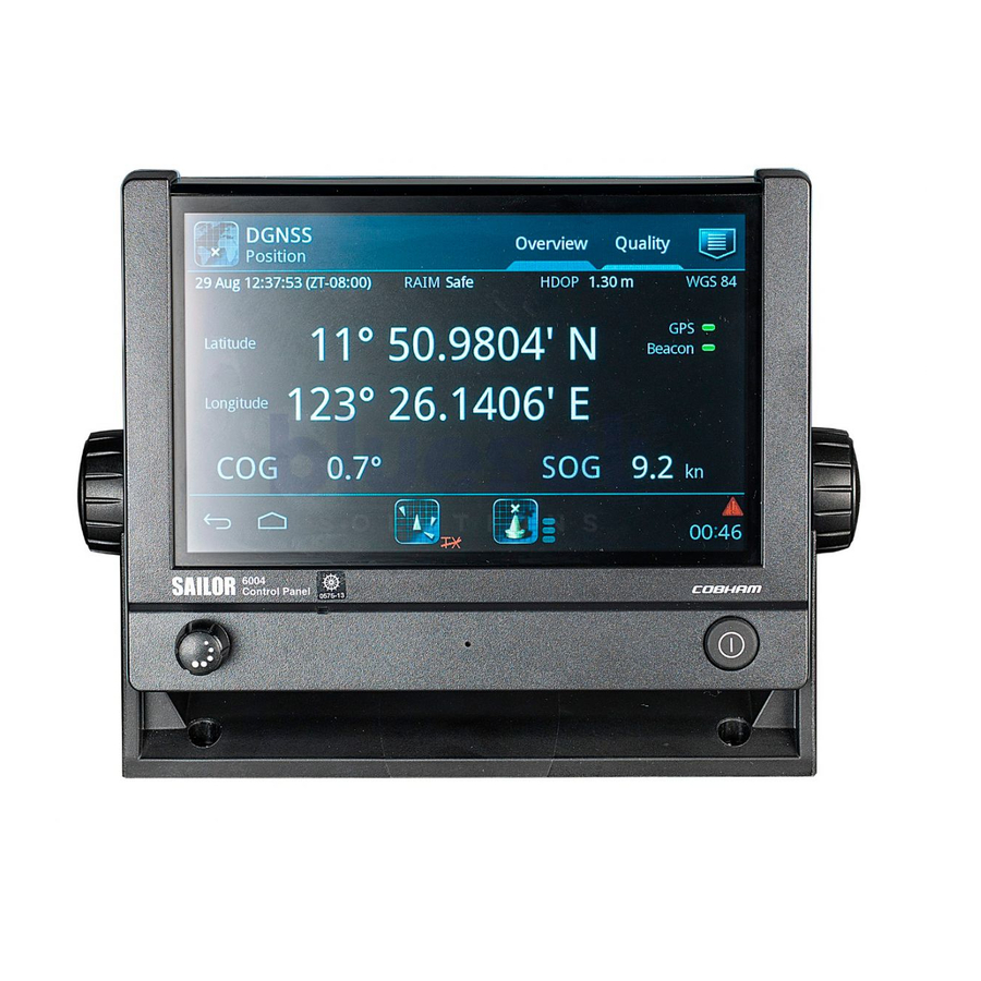
INSTALLATION MANUAL
SAILOR 6004 Control Panel
Related Manuals for Sailor 6004
Summary of Contents for Sailor 6004
-
Page 1
INSTALLATION MANUAL SAILOR 6004 Control Panel… -
Page 3
SAILOR 6004 Control Panel Installation manual Document number: 98-136644-A Release date: January 3, 2013… -
Page 4
• Thrane & Thrane is a registered trademark of Thrane & Thrane A/S in the European Union and the United States. • SAILOR is a registered trademark of Thrane & Thrane A/S in the European Union, the United States and other countries. -
Page 5
Safety summary The following general safety precautions must be observed during all phases of operation, service and repair of this equipment. Failure to comply with these precautions or with specific warnings elsewhere in this manual violates safety standards of design, manufacture and intended use of the equipment. -
Page 6
About the manual Intended readers This manual is an installation for the SAILOR 6004 Control Panel. The manual is intended primarily for installers of the system and service personnel. Personnel installing or servicing the system must be properly trained and authorized by Thrane & Thrane. It is… -
Page 7: Table Of Contents
Table of Contents Chapter 1 Introduction The SAILOR 6004 Control Panel ……..1 ………… 1 1.1.1 General description ……….2 1.1.2 Key features and functions ……..2 1.1.3 System configuration example Chapter 2 Installation 2.1 Unpacking …………..4 …………4 2.1.1 Initial inspection …………..4 2.1.2…
-
Page 8
Table of Contents Chapter 4 Verification 4.1 Overview …………..19 4.2 Check of the Control Panel ……..19 ……….. 20 4.2.1 Running a self test …….. 22 4.2.2 Test log and further information Chapter 5 Service & repair 5.1 General service information ……..23 5.2 Maintenance &… -
Page 9: The Sailor 6004 Control Panel
The Control Panel can be remotely switched on. The basic configuration application for ThraneLINK is already installed in the Control Panel upon shipping. All individual applications are installed and updated from the attached devices (e.g. SAILOR 628x AIS, SAILOR 6390 Navtex Receiver, SAILOR 100 Satellite TV, etc.).
-
Page 10: Key Features And Functions
• Dual LAN (2 Ethernet connectors) • ThraneLINK compatible • Handling of multiple applications • Amplifier for external speaker, e.g. SAILOR 6270 Loudspeaker • Rear mounted USB (x2, e.g. for external keyboard) • Connector for SAILOR 6201 Handset or similar 1.1.3 System configuration example…
-
Page 11: Installation
Chapter 2 Installation This chapter provides a description of how to unpack, store and install the Control Panel. It contains the following sections: • Unpacking • Installing the Control Panel For information on cable connections see chapter 3 Connectors & controls on page 11.
-
Page 12: Unpacking
Chapter 2: Installation 2.1 Unpacking 2.1.1 Initial inspection Inspect the shipping carton immediately upon receipt for evidence of damage during transport. If the shipping carton is severely damaged or water stained, request that the carrier’s agent be present when opening the carton. Save the carton packing material for future use.
-
Page 13: Installing The Control Panel
Chapter 2: Installation 2.2 Installing the Control Panel When installing, make sure the Compass Safe Distance of 0.6 m is maintained. The Control Panel can be mounted in two ways, if needed with the cable relief: • Desktop mounting • Flush mount — typically in a console •…
-
Page 14
Chapter 2: Installation To mount the Control Panel using the mounting bracket, do as follows: 1. Find a suitable location to mount the Control Panel. Make sure there is minimum 80 mm of free space for cable access behind the Control Panel. 80 mm 60.5 mm Space for… -
Page 15: Flush Mount
Chapter 2: Installation 4. Mount the two knobs on the sides of the bracket, but do not tighten them yet. 5. Connect the cables as described in chapter 3. 6. Adjust the angle of the Control Panel to the wanted position. The bracket can be adjusted ±…
-
Page 16
Chapter 2: Installation 3. Ensure that the flush mount gasket is placed correctly on the Control Panel. 4. Fit the Control Panel into the cut-out in the console. Flush Mount Gasket Flush Mount Bracket (2 pcs.) Screw M4x65 Torx 20 (4 pcs.) Max Wall Thickness Installing the Control Panel… -
Page 17
Chapter 2: Installation 5. Mount the flush mount brackets on the back of the Control Panel by mounting the 4 Torx screws through the bracket and into the Control Panel. Screw M3x8 Countersink (3 pcs.) Cable Relief Plate 6. Fasten the 4 Torx screws. 7. -
Page 18: Mounting The Cable Relief Bracket
Chapter 2: Installation 2.2.3 Mounting the cable relief bracket A cable relief bracket is included in the delivery. You can fasten it to the rear panel. See the previous section for an example how to mount the cable relief bracket. Installing the Control Panel…
-
Page 19: Connectors & Controls
Chapter 3 Connectors & controls This chapter provides a description of all connectors on the Control Panel and gives guidelines to cabling. It has the following sections: • Connectors • Cabling • Controls 3.1 Connectors The drawing below shows the connectors and the ground stud on the rear panel of the Control Panel.
-
Page 20: Auxiliary Connector (Aux)
Chapter 3: Connectors & controls 3.1.1 Auxiliary connector (AUX) Pin 1 & 2 are for output to an external 8 Ohm loudspeaker, e.g. a SAILOR 6270 Loudspeaker. The internal audio amplifier can deliver up to 6 W. Pin 4 & 5 are for alarm output. Both outputs are open collector (OC) and can sink up to 100 mA.
-
Page 21: Usb Connector
Chapter 3: Connectors & controls Pin assignment: Connector front view on the rear panel of the Control Panel. Description Wire color NMEA in+ Brown NMEA in- Blue NMEA out+ White NMEA out- Green Yellow Grey Hook_PTT Pink 12 V Black Orange 3.1.3 USB connector You can use the 2 USB connectors to connect ancillary equipment.
-
Page 22: Dc Power Input 12-24 V Dc (Pwr)
Chapter 3: Connectors & controls 3.1.4 DC Power input 12—24 V DC (PWR) The DC Power input connects to a DC supply with 12—24 V DC nominal (10.8 to 31.2 V DC). The Power connector is a custom connector; a matching cable with connector is included in the delivery.
-
Page 23
Chapter 3: Connectors & controls Connecting Remote on (ON_IN) With the Remote on function you can switch the Control Panel on from a remote location, without using the on/off button on the terminal. To connect the Remote on function in the Control Panel, do as follows: 1. -
Page 24: Lan Connector
Chapter 3: Connectors & controls 3.1.5 LAN connector There are 2 LAN (10/100 Mbit/s Ethernet) connectors on the rear panel of the Control Panel, used for communication with connected equipment that is designed to be operated by the Control Panel. Important For GMDSS installations: Only connect units that are part of the system.
-
Page 25: Cabling
Chapter 3: Connectors & controls 3.2 Cabling Before using the Control Panel for the first time, check that all cables are correctly wired and fastened. All cables attached to the Control Panel must be shielded. • The shield of the Ethernet cable must be connected to ship ground or an Ethernet switch to which the Control Panel is connected.
-
Page 26: Connecting Cables
Chapter 3: Connectors & controls 3.2.3 Connecting cables To connect the Control Panel, do as follows: 1. Connect an Ethernet cable to the LAN connector on the Control Panel. For 1 cable, use the lower LAN connector (Primary LAN). Both connectors work in DHCP and zeroconf environments.
-
Page 27: Chapter 4 Verification
Chapter 4 Verification 4.1 Overview With the built-in self test you can do the following: • Test the basic functions of the Control Panel • Display the test results • Export the test results in a test log • Show various unit information 4.2 Check of the Control Panel To verify the proper functioning of the Control Panel, run a self test.
-
Page 28: Running A Self Test
Chapter 4: Verification 4.2.1 Running a self test To run a self test, do as follows: 1. Press the power button to switch the Control Panel on. The display shows the example below or the start screen of the already installed application: 2.
-
Page 29
Chapter 4: Verification You can test the following parts and functions: • Touch — the touch screen • Controls — power button and dim/volume knob • Display — pixel and colour check • Audio — test of microphone and loudspeaker •… -
Page 30: Test Log And Further Information
Chapter 4: Verification 4.2.2 Test log and further information Tap the icon in the upper right corner to display the list of options. They show which type of further information is available. The following options are available: Option Description Show production Shows the test results from the production tests.
-
Page 31: Chapter 5 Service & Repair
Chapter 5 Service & repair This chapter describes what to do with defective units, including how to pack them for shipment if they are to be returned. 5.1 General service information The Control Panel is designed to operate without preventive routine maintenance.
-
Page 32: Repacking For Shipment
Chapter 5: Service & repair There is a special access on the back of the unit reserved for service and repair. Reserved service & repair TEST 5.3 Repacking for shipment The shipping carton has been carefully designed to protect the Control Panel and its accessories during shipment.
-
Page 33: Technical Specifications
Appendix A Technical specifications Item Specifications Mounting method Flush mount or bracket Voltage 10.8 to 31.2 V DC Power consumption Typical: 18 W active Peak: 42 W 3.15 A internal fuse (non-serviceable) Audio input Up to 6 W in 8 Ohm Interfaces 2 x Ethernet (10/100 Mbit/s) Accessories connector…
-
Page 34
Appendix A: Technical specifications… -
Page 35: Glossary
Glossary Glossary American Wire Gauge. A means of specifying wire diameters. Direct Current DHCP Dynamic Host Configuration Protocol. A protocol for assigning dynamic IP addresses to devices on a network. With dynamic addressing, a device can have a different IP address every time it connects to the network. Film Twisted Pair GMDSS Global Maritime Distress and Safety System.
-
Page 36
Glossary Local Area Network. A computer network covering a small physical area, like a home, office, school or airport. The defining characteristics of LANs, in contrast to wide-area networks (WANs), include their usually higher data-transfer rates, smaller geographic area, and lack of a need for leased telecommunication lines. -
Page 37: Index
Index Index ACC connector, 12 Ethernet alarm output, 1, 12 cable, 17 Auxiliary connector, 12 connector, 16 brightness, 18 flush mount, 7 attach brackets, 9 cutout measures, 7 fuse, 25 cable Ethernet, 17 power, 17 cable relief bracket, 10 grounding, 17 cable requirements, 17 clean touch screen, 23…
-
Page 38
Index loudspeaker self test, 19 connect, 12 LAN, 21 self test, 21 start, 20 service, 23 software version, 22 specifications, 25 storage, 4 microphone self test, 21 mounting desktop, 5 flush mount, 7 ThraneLINK, 1 touch screen cleaning, 23 lock, 23 self test, 21 night mode, 18 NMEA… -
Page 40
98-136644-A info@thrane.com www.thrane.com •…
The following general safety precautions must be observed during all
phases of operation, service and repair of this equipment. Failure to comply
with these precautions or with specific warnings elsewhere in this manual
violates safety standards of design, manufacture and intended use of the
equipment. Thrane & Thrane assumes no liability for the customer’s failure
to comply with these requirements.
DO NOT OPERATE IN AN EXPLOSIVE ATMOSPHERE
Do not operate the equipment in the presence of flammable gases or fumes.
Operation of any electrical equipment in such an environment constitutes a
definite safety hazard.
KEEP AWAY FROM LIVE CIRCUITS
Operating personnel must not remove equipment covers. Component
replacement and internal adjustment must be made by qualified
maintenance personnel. Do not service the unit with the power cable
connected. Always disconnect and discharge circuits before touching them.
DO NOT SUBSTITUTE PARTS OR MODIFY EQUIPMENT
Because of the danger of introducing additional hazards, do not substitute
parts or perform any unauthorized modification to the equipment.
COMPASS SAFE DISTANCE
Minimum compass safe distance: 0.6 m.
Warning! If the Control Panel is flush-mounted in a console with
Safety summary
high ambient air temperature (above 45°C), caution
shall be taken to avoid skin burns when servicing the
rear metal part of unit.
1
iii
|
Detail Specifications: 900/900659-6004.pdf file (01 Feb 2023) |
Accompanying Data:
Sailor 6004 Marine Equipment PDF Installation Manual (Updated: Wednesday 1st of February 2023 02:41:37 PM)
Rating: 4.1 (rated by 25 users)
Compatible devices: DBS721, 6222, TP10, Inmarsat B, 6300, RT5022, MI-WSO-XX-I, 6207.
Recommended Documentation:
Text Version of Installation Manual
(Ocr-Read Summary of Contents, UPD: 01 February 2023)
-
16, Sailor 6004 Chapter 2: Installation 8 Installing the Control Panel 3. Ensure that the flush mount gasket is placed correctly on the Control Panel. 4. Fit the Control Panel into the cut-out in the console. Screw M4x65 Torx 20 (4 pcs.) Flush Mount Bracket (2 pcs.) Flush Mount Gasket 20Max Wall Thickness mm ControlPanel.book Page 8 Thursday, January 3, 2013 12:28 PM
… -
7, v Table of Contents Chapter 1 Introduction 1.1 The SAILOR 6004 Control Panel …………………………….1 1.1.1 General description ……………………………………………. 1 1.1.2 Key features and functions ……………………………………2 1.1.3 System configuration example ……………………………….2 Chapter 2 Installation 2.1 Unpacking …..…
-
35, 27 Glossary BBBBB Glossary Glossary B A AWG American Wire Gauge. A means of specifying wire diameters. D DC Direct Current DHCP Dynamic Host Configuration Protocol. A protocol for assigning dynamic IP addresses to devices on a network. With dynamic addressing, a device can have a different IP address every time it connects to the network. F FTP Film Twisted Pair G GMDSS Glo…
-
8, Sailor 6004 Table of Contents vi Chapter 4 Verification 4.1 Overview ………………………………………………………….19 4.2 Check of the Control Panel ………………………………….19 4.2.1 Running a self test …………………………………………… 20 4.2.2 Test log and further information ………………………….. 22 Chapter 5 Service &…
-
6, iv About the manual 2 Intended readers This manual is an installation for the SAILOR 6004 Control Panel. The manual is intended primarily for installers of the system and service personnel. Personnel installing or servicing the system must be properly trained and authorized by Thrane & Thrane. It is important that you observe all safety requirements listed in the beginni…
-
29, Sailor 6004 Chapter 4: Verification Check of the Control Panel 21 44444 Verification You can test the following parts and functions: • Touch — the touch screen • Controls — power button and dim/volume knob • Display — pixel and colour check • Audio — test of microphone and loudspeaker • USB — test of USB connection • Light sensor • Alarm output — test of connectio…
-
3, SAILOR 6004 Control Panel Installation manual Document number: 98-136644-A Release date: January 3, 2013 ControlPanel.book Page i Thursday, January 3, 2013 12:28 PM
… -
14, Chapter 2: Installation 6 Installing the Control Panel To mount the Control Panel using the mounting bracket, do as follows: 1. Find a suitable location to mount the Control Panel. Make sure there is minimum 80 mm of free space for cable access behind the Control Panel. 2. Use the four holes to fasten the mounting bracket to the mounting surface, see the drilling plan …
-
36, Glossary 28 L LAN Local Area Network. A computer network covering a small physical area, like a home, office, school or airport. The defining characteristics of LANs, in contrast to wide-area networks (WANs), include their usually higher data-transfer rates, smaller geographic area, and lack of a need for leased telecommunication lines. N NMEA National Marine Electron…
Recommended Instructions:
KH 6515, 10.525.1722K, 26-762, 4300G, V171HT


-
NEDERLANDS 9ENGLISH 21DEUTSCH 33FRANÇAIS 45ESPAÑOL 57ITALIANO 69DANSK 81SVENSKA 93NORSK 105SUOMEKSI 117POLSKI 129BOWB065 — BOWB076 — BOWB090 — BOWB110 — BOWB13065 kgf — 130 kgf — ø 185 mm020808.02Installation instructionsInstallatie instructies EinbauanleitungInstructions d’installationInstrucciones de instalaciónIstruzioni per l’installazioneInstall …
BOW PRO B Series 160
-
30198-004b 1 Betriebs- und Montageanleitung für Schallgeber PA 130 Der PA130 ist ein leistungsstarker Schallgeber mit sehr hohem Schallpegel, der besonders für die Alarmierung unter lauten Um-gebungsbedingungen, über große Bereiche, in Fertigungseinrichtungen und im Zivilschutz geeignet ist. Die für den Innen- und Außeneinsatz geeigneten Schallgeber können War …
PA 130 16
-
…
DL112H 12
-
Page 1 of 2Twist-n-Stow (up control line) Bungee replacement / OutfitterThis kit is designed to help improve the performance of your Twist and Stow Rudder if originally supplied with a Bungee on theup control line as described below. Please follow the instructions to complete this modification.1) Place the rudder in the up position with the retaining bungee fastened overthe rudder 2) Prop the …
Twist-n-Stow 2