- Manuals
- Brands
- Amazone Manuals
- Farm Equipment
- UG 3000 Special
Manuals and User Guides for Amazone UG 3000 Special. We have 1 Amazone UG 3000 Special manual available for free PDF download: Operating Manual
Инструкции по эксплуатации
Здесь Вы можете бесплатно просмотреть инструкции по эксплуатации Ваших AMAZONE-машин в формате PDF.
Перечень запасных частей
Портал запасных частей AMAZONE предлагает свободный доступ к перечню запасных частей для машин AMAZONE. Здесь Вы можете найти информацию о различных деталях.
Проспекты
На нашем информационном портале представлены различные проспекты для просмотра и скачивания – бесплатно.
Практические отчеты / Отчеты о тестах из специализированных изданий
В данной рубрике мы размещаем отчеты о проведенных тестах и отзывы наших пользователей. Отчеты опубликованые в специализированных изданиях, которые любезно предоставляют нам свои статьи.
Таблицы распределения
При составлении таблиц распределения и рекомендаций по настройкам используются современные методы обработки данных, моделирования и анализа.
Таблицы норм высева
Указанные в таблице норм высева значения являются ориентировочными, поскольку относятся к определенной объёмной массе, размеру и форме семян, содержанию влаги в посевном материале, который на практике может быть весьма различным. Поэтому для достижения точной нормы высева мы рекомендуем регулярно проводить калибровку (см. инструкцию по эксплуатации).
Фотоматериалы
Здесь Вы можете выбрать фотографии/картинки, бесплатно скачать и опубликовать их.
Sonstiges
In unserem Info-Portal stellen wir Ihnen Dokumente verschiedenster Art zur Ansicht und zum Download bereit — kostenlos. Das können technische und werbende Drucksachen als elektronische Version sein, aber auch Videos, Internet-Links und Kontaktdaten. Informationen lassen sich per Post beziehen und neu veröffentlichte Dokumente aus verschiedenen Kategorien sind abonnierbar.
- Amazone
- Сервис и поддержка
- Для фермеров, подрядных организаций и муниципальных образований
- Сервисная служба
- Материалы для скачивания
User Manuals, Guides and Specifications for your Amazone UG 3000 Special Farm Equipment. Database contains 1 Amazone UG 3000 Special Manuals (available for free online viewing or downloading in PDF): Operating manual .


В 2011 году АПК «Тюринский» приобрел навесной опрыскиватель UG 3000 Nova немецкой компании AMAZONE, предназначенный для приготовления, транспортировки и внесения химических средств защиты растений.
Далеко не дешевый, но удобный в использовании и неприхотливый в обслуживании опрыскиватель AMAZONE UG 3000 Nova за три года эксплуатации показал высокие показатели производительности. Так в 2011 году с помощью опрыскивателя UG 3000 Nova была обработана площадь в 281 га, в 2012 году — 1300 га, а в 2013 году площадь обрабатываемой территории увеличилась до 1580 га.
Однако, несмотря на знаменитое немецкое качество, весной 2013 году у опрыскивателя AMAZONE UG 3000 Nova сломалась металлическая ось крепления штанги. Толстый монолитный кусок железа ни с того ни с сего просто сломался напополам! При естественных условиях эксплуатации увидеть такое мы конечно не ожидали, и поэтому надежность машины от компании AMAZONE оказалась под вопросом.
Так как поломка произошла в самый разгар работ, мы попытались произвести ремонт машины собственными силами и кустарным способом изготовили недостающую часть, отдаленно напоминающую оригинальную деталь. Очевидно, что самодельная ось не так хороша, как абсолютно новая «железка» от производителя, и к тому же она не обеспечивает необходимую безопасность эксплуатации опрыскивателя.
Учитывая, что такую поломку никак нельзя списать на естественный износ или на неправильную эксплуатацию агрегата, мы написали об этой ужасной несправедливости непосредственно производителю – компании AMAZONE, приложив к письму фотографии сломавшегося узла.
Посмотрим, очистит ли немецкий производитель свое доброе имя присылкой нам новой «железки» взамен треснувшей пополам, и отчитаемся об этом здесь же.
Дополнение от 27 марта 2014 года:
Долго ли, коротко шла переписка и вот, как и обещали, отчитываемся перед вами, уважаемые читатели, о результатах переговоров с производителем. Российское представительство AMAZON-а не пожелало ни признать просчетов в конструкции устройства, ни бесплатно поставить нам материалы для ремонта опрыскивателя. Головное же отделение, в Германии, хоть и не согласилось с тем, что случай гарантийный, но все же решило безвозмездно прислать нам запчасти для ремонта сломавшегося узла — пластины и ось. Как говорится, и на том спасибо.

AMAZONE UG 3000 Nova

Треснувшая пополам металлическая ось

Самодельная ось

Приваренная самодельная ось

Отремонтированный собственными силами опрыскиватель

Запчасти из Германии добрались до нас
-
Contents
-
Table of Contents
-
Bookmarks
Quick Links
UG 2200 Super
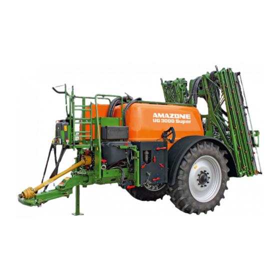
UG 3000 Super
MG3506
BAG0021.14 05.19
Printed in Germany
en
Operating Manual
az
Trailed Field Sprayer
UG 2200 Special
UG 3000 Special
Please read this operating
manual before commissioning.
Keep it in a safe place
for future use.
Related Manuals for Amazone UG 2200 Super
Summary of Contents for Amazone UG 2200 Super
-
Page 1
Operating Manual UG 2200 Super UG 2200 Special UG 3000 Super UG 3000 Special Trailed Field Sprayer Please read this operating MG3506 manual before commissioning. BAG0021.14 05.19 Keep it in a safe place Printed in Germany for future use. -
Page 2
Reading the instruction Manual and following it should seem to be in- convenient and superfluous as it is not enough to hear from others and to realize that a machine is good, to buy it and to believe that now everything should work by itself. -
Page 3
+ 49 (0)5405 501-0 E-mail: amazone@amazone.de Spare part orders Spare parts lists are freely accessible in the spare parts portal at www.amazone.de. Please send orders to your AMAZONE dealer. Formalities of the operating manual Document number: MG3506 Compilation date: 05.19 … -
Page 4
Dear Reader, We update our operating manuals regularly. Your suggestions for improvement help us to create ever more user-friendly manuals. AMAZONEN-WERKE H. DREYER GmbH & Co. KG Postfach 51 D-49202 Hasbergen, Germany Tel.: + 49 (0)5405 501-0 E-mail: amazone@amazone.de BAG0021.14 05.19… -
Page 5: Table Of Contents
Table of Contents User Information ………………10 Purpose of the document ………………….. 10 Locations in the operating manual ………………10 Diagrams ……………………..10 General safety instructions …………… 11 Obligations and liability ………………….11 Representation of safety symbols ………………13 Organisational measures ………………….. 14 Safety and protection equipment ……………….
-
Page 6
Table of Contents Structure and function …………….53 Functionality …………………….. 53 Control terminal ……………………55 PTO shaft ……………………..59 5.3.1 Coupling the PTO shaft ………………….61 5.3.2 Uncoupling the PTO shaft ………………… 62 Hydraulic connections ………………….63 5.4.1 Coupling hydraulic hose lines ………………..65 5.4.2 Disconnecting hydraulic hose lines ……………… -
Page 7
Table of Contents Construction and function of the sprayer boom ……..99 Super-L1-Gestänge ………………….101 Super-S boom ……………………102 Part width section valve TG ………………..104 Outer boom locking ………………….104 Spacer ……………………..105 Swing compensation ………………….106 Folding via the tractor control unit ………………107 6.7.1 Working with the sprayer boom folded out on one side ………… -
Page 8
Table of Contents 10.3 Filling with water ……………………166 10.3.1 Filling the spray liquid tank via the filling opening …………… 167 10.3.2 Filling the spray liquid tank via the suction port on the control terminal ……167 10.4 Filling the fresh water tank ………………..169 10.5 Inducting agents …………………… -
Page 9
Table of Contents 12.13.4 Check and replace suction and pressure valves (workshop work)……..224 12.13.5 Checking and replacing piston diaphragms (workshop work) ……….225 12.14 Calibrate the flow meter ………………….. 226 12.15 Eliminating limescale in the system ………………227 12.16 Field sprayer calibration ………………….. -
Page 10: User Information
User Information User Information The User Information section provides information on use of the oper- ating manual. Purpose of the document This operating manual • describes the operation and maintenance of the machine. • provides important information on safe and efficient handling of the machine.
-
Page 11: General Safety Instructions
General safety instructions General safety instructions This section contains important information on safe operation of the machine. Obligations and liability Comply with the instructions in the operating manual Knowledge of the basic safety information and safety regulations is a basic requirement for safe handling and fault-free machine operation. Obligations of the operator The operator is obliged only to let those people work with/on the ma- chine who…
-
Page 12
General safety instructions Risks in handling the machine The machine has been constructed to the state-of-the art and the recognised rules of safety. However, operating the machine may cause risks and restrictions to • the health and safety of the user or third parties, •… -
Page 13: Representation Of Safety Symbols
General safety instructions Representation of safety symbols Safety instructions are indicated by the triangular safety symbol and the highlighted signal word. The signal word (DANGER, WARNING, CAUTION) describes the gravity of the risk and has the following sig- nificance: DANGER Indicates an immediate high risk which will result in death or serious physical injury (loss of body parts or long term damage) if not avoided.
-
Page 14: Organisational Measures
General safety instructions Organisational measures The operator must provide the necessary personal protective equip- ment as per the information provided by the manufacturer of the crop protection agent to be used, such as: • Chemical-resistant gloves, • Chemical-resistant overalls, • Water-resistant footwear, •…
-
Page 15: User Training
General safety instructions User training Only those people who have been trained and instructed may work with/on the machine. The operator must clearly specify the responsi- bilities of the people charged with operation, maintenance and repair work. People being trained may only work with/on the machine under the supervision of an experienced person.
-
Page 16: Safety Measures In Normal Operation
General safety instructions Safety measures in normal operation Only operate the machine if all the safety and protection equipment is fully functional. Check the machine at least once a day for visible damage and check the function of the safety and protection equipment. Danger from residual energy Note that there may be residual mechanical, hydraulic, pneumatic and electrical/electronic energy on the machine.
-
Page 17: Spare And Wear Parts And Aids
Immediately replace any machine parts which are not in a perfect state. Only use genuine AMAZONE spare and wear parts, or those ap- proved by AMAZONEN-WERKE, so that the type approval remains valid according to the national and international regulations. The use…
-
Page 18: Warning Symbols And Other Signs On The Machine
General safety instructions 2.13 Warning symbols and other signs on the machine Always keep all the warning symbols on the machine clean and in a legible state. Replace illegible warning symbols. You can obtain the warning symbols from your dealer using the order number (e.g.
-
Page 19: Positions Of Warning Symbols And Other Labels
General safety instructions 2.13.1 Positions of warning symbols and other labels Warning symbols The following diagrams show the arrangement of the warning symbols on the machine. Fig. 1 BAG0021.14 05.19…
-
Page 20
General safety instructions Order number and explanation Warning symbols MD 078 Risk of crushing fingers or hands by acces- sible moving machine parts. This danger causes serious injuries, including loss of body parts such as fingers or hand. Never reach into the danger area while the trac- tor engine is running and the PTO shaft / hydrau- lic system is connected. -
Page 21
General safety instructions MD 094 Danger from electric shock or burns due to unintentional contact with electric transmis- sion lines or from approaching high-voltage transmission lines without authorisation. These dangers can cause extremely serious and potentially fatal injuries. Maintain an adequate safety distance from transmission lines carrying high voltage. -
Page 22
General safety instructions MD101 This symbol indicates jacking points for lifting gear (jack). MD 102 Danger from intervention in the machine, e.g. installation, adjusting, troubleshooting, cleaning, maintaining and repairing, due to the tractor and the machine being started unintentionally and rolling. These dangers can cause extremely serious and potentially fatal injuries. -
Page 23
General safety instructions MD 139 The torque of the screw connection is 450 Nm. MD 153 This pictogram indicates a hydraulic oil filter. MD158 When using wheels that are not factory assem- bled, ensure that the rim only touches the wheel hub and not the brake drum! MD 159 Only fill the hand wash tank with clear fresh wa-… -
Page 24
General safety instructions MD 173 Risk of breathing in hazardous materials via poisonous vapours from the spray liquid tank. This danger can cause extremely serious and potentially fatal injuries. Never climb into the spray liquid tank. MD 174 Danger from unintended continued movement of the machine. -
Page 25
General safety instructions MD 224 Risk of contact with hazardous materials due to improper use of clear fresh water from the hand wash tank. This danger can cause extremely serious and potentially fatal injuries. Never use the clear fresh water from the hand wash tank as drinking water. -
Page 26: Potential Risks From Not Observing The Safety Instructions
General safety instructions 2.14 Potential risks from not observing the safety instructions Non-compliance with the safety information • can pose both a danger to people and also to the environment and machine. • can lead to the loss of all warranty claims. In particular, non-compliance with the safety information could pose the following risks: •…
-
Page 27: Safety Information For Users
General safety instructions 2.16 Safety information for users WARNING Risk of crushing, cutting, being trapped or drawn in, or impact through inadequate roadworthiness and operational safety. Before starting up the machine and the tractor, always check their roadworthiness and operational safety. 2.16.1 General safety and accident prevention information •…
-
Page 28
General safety instructions • When coupling and uncoupling machines, move the support equipment (if available) to the appropriate position (stability). • When actuating the support equipment, there is a risk of injury from crushing and cutting points. • Be particularly careful when coupling the machine to the tractor or uncoupling it from the tractor. -
Page 29
General safety instructions Machine transportation • When using public highways, national road traffic regulations must be observed. • Before moving off, check: ο the correct connection of the supply lines ο the lighting system for damage, function and cleanliness ο the brake and hydraulic system for visible damage ο… -
Page 30: Hydraulic System
• Replace the hydraulic hose lines if they are damaged or worn. Only use AMAZONE original hydraulic hose lines. • The hydraulic hose lines should not be used for longer than six years. This period includes any storage time of a maximum of two years.
-
Page 31: Electrical System
General safety instructions 2.16.3 Electrical system • When working on the electrical system, always disconnect the battery (negative terminal). • Only use the prescribed fuses. If fuses are used with too high a rating, the electrical system will be destroyed – danger of fire. •…
-
Page 32: Universal Joint Shaft Operation
General safety instructions 2.16.4 Universal joint shaft operation • Use only the PTO shafts prescribed by the AMAZONEN-WERKE factories, equipped with the proper safety devices. • Also read and follow the operating manual from the PTO shaft manufacturer. • The protective tube and PTO shaft guard must be undamaged, and the shield of the tractor and machine universal joint shaft must be attached and be in proper working condition.
-
Page 33: Coupled Machines
General safety instructions • After removing the PTO shaft, attach the protective sleeve to the universal joint shaft stub. • When using the travel-dependent universal joint shaft, note that the universal joint shaft speed depends on the drive speed, and that the direction of rotation reverses when you drive in reverse.
-
Page 34: Tyres
General safety instructions Pneumatic braking system • Before coupling the machine, clean the sealing rings on the hose couplings of the supply and brake line. • Only move off with the machine connected when the pressure gauge on the tractor shows 5.0 bar. •…
-
Page 35: Field Sprayer Operation
Observe the information in the German Plant Protection Law. • Never open lines which are under pressure. • Only use genuine AMAZONE replacement hoses, which stand up to chemical, mechanical and thermal requirements. Only use hose clamps made from V2A for installation. •…
-
Page 36: Cleaning, Maintenance And Repairs
• Spare parts must meet at least the specified technical require- ments of AMAZONEN-WERKE. This is ensured through the use of AMAZONE original spare parts. • When repairing field sprayers which have been used for liquid fertiliser application with ammonium nitrate / urea solution, ob-…
-
Page 37: Loading And Unloading
Loading and unloading Loading and unloading Loading and unloading with a tractor WARNING There is a risk of accident if the tractor is unsuitable and the machine brake system is not connected to the tractor or filled. • Couple the machine to the tractor correctly before loading the machine onto a transport vehicle or unloading it from a transport vehicle.
-
Page 38: Product Description
Product description Product description This section: • provides a comprehensive overview of the machine structure. • provides the names of the individual modules and controls. If possible, read this section when actually at the machine. This helps you to understand the machine better. Overview of the assemblies Fig.
-
Page 39
Product description Fig. 4 (1) Flushing water tank (5) Pump equipment (2) Flushing water tank, filling opening (6) Wheel chocks (3) Parking brake (7) Hydraulic block with system setting screw, job computer (optional) (4) Stand (8) Super S sprayer boom (9) Transport box BAG0021.14 05.19… -
Page 40: Safety And Protection Equipment
Product description Safety and protection equipment • Transport locking mechanism to prevent the Super- S boom from folding out uninten- tionally Fig. 5 • Transport locking mechanism on the Super-L1 boom to prevent unintentional unfold- ing. ο Boom support on the inner boom Fig.
-
Page 41: Supply Hoses Between The Tractor And The Machine
Product description • PTO shaft guard • Machine PTO shaft guard Fig. 9 • Stop tap on AutoTrail drawbar against unin- tentional activation of the track follow steer- ing. Fig. 10 Supply hoses between the tractor and the machine Supply hoses in parking position: Fig.
-
Page 42: Transportation Equipment
Product description Transportation equipment Fig. 13/… (1) rear lights, brake lights, turn (2) 2 warning signs (square) (3) 2 red reflectors (triangular) (4) 1 registration plate holder with lighting (5) Reflector on the side of the boom (6) Additional rear light and brake light Fig.
-
Page 43: Intended Use
Compliance with all the instructions in this operating manual. • Execution of inspection and maintenance work. • Exclusive use of genuine AMAZONE spare parts. Other uses to those specified above are forbidden and shall be con- sidered as improper. For any damage resulting from improper use: •…
-
Page 44: Regular Device Inspections
However their service life is reduced by use at low temperatures (e.g. AUS in frosty conditions). The materials and components used in the construction of AMAZONE field sprayers are safe for liquid fertiliser. BAG0021.14 05.19…
-
Page 45: Danger Areas And Danger Points
Product description Danger areas and danger points The danger area is the area around the machine in which people can be caught by: • work movements made by the machine and its tools • materials or foreign bodies thrown out of the machine •…
-
Page 46: Rating Plate And Ce Mark
Product description Rating plate and CE mark EU rating plate (1) Class, sub-class and speed class (2) EU type approval number (3) Vehicle identification number (4) Technically permissible total weight (5) Technically permissible drawbar load A0 (6) Technically permissible axle load A1 Machine rating plate The machine rating plate specifies: (1) Vehicle ID no.
-
Page 47: Technically Possible Maximum Application Rate
Product description 4.11 Technically possible maximum application rate The application rate of the implement is limited by the following fac- tors: • Maximum flow to the sprayer boom of 200 l/min (HighFlow 400 l/min). • Maximum flow per part-width section of 25 l/min (with 2 spray lines: 40 l/min per part-width section).
-
Page 48: Maximum Permissible Application Rate
Product description 4.12 Maximum permissible application rate The permissible application rate of the implement is limited by the minimum required agitator capacity. The agitator capacity per minute should be 5% of the hopper volume. This is particularly applicable for active substances that are hard to keep in suspension.
-
Page 49: Technical Data
Product description 4.13 Technical data 4.13.1 Basic implement The basic weight consists of the sum of the weights of the basic im- plement, optional equipment, and special equipment. Typ UG 2200 3000 Spray liquid tank • Actual volume 2400 l 3200 l •…
-
Page 50: Payload
Product description 4.13.2 Payload Payload = Permissible axle load + Permissible drawbar Basic weight load DANGER Exceeding the permitted payload is prohibited. Risk of accident because of unstable driving conditions. Carefully determine the payload, and therefore the permitted filling amount for your machine. Not all filling media can be used to fill the tank completely.
-
Page 51: Noise Emissions Data
Product description Driving with reduced inflation pressure • When the inflation pressure is lower than the nominal pressure, the tyre load capacity is reduced! In that case, observe the reduced payload of the implement. • Please also follow the specifications of the tyre manufacturer! WARNING Danger of accident! In event of too low inflation pressure, the stability of the vehicle…
-
Page 52: Required Tractor Equipment
Product description 4.15 Required tractor equipment For the machine to be operated as intended, the tractor must fulfil the following requirements: Tractor engine power UG 2200 from 65 kW (90 hp) upwards UG 3000 from 75 kW (100 hp) upwards Electrical system •…
-
Page 53: Structure And Function
Structure and function Structure and function The following section provides information on the machine structure and the functions of the individual components. Functionality UG Special UG Super BAG0021.14 05.19…
-
Page 54
Structure and function The piston diaphragm pump (2) draws the spray liquid from the spray liquid tank (1) via the VARIO switch tap, suction side (A), the suction line (3) and the suction filter (4). The spray liquid which is drawn up is conveyed via the pressure hose (5) to the VARIO switch tap, pressure side (B). -
Page 55: Control Terminal
Structure and function Control terminal Fig. 15 (1) Spray liquid tank filling connection (via suc- (10) Connection for Ecofill tion hose) (11) Connection for Ecofill flushing (2) Flushing water tank filling connection (A) VARIO switch tap, suction side (3) Suction filter (B) VARIO switch tap, pressure side (4) Filling connection for spray liquid tank (op- (C) Setting tap for agitator / pressure filter…
-
Page 56
Structure and function • – VARIO switch tap, suction side ο Draw from an external source ο Draw from the flushing water tank ο Draw from the spray tank ο Drain the technical residue from the spray liquid tank Fig. 16 ο… -
Page 57
Structure and function • – Filling switch tap / Rapid draining (optional) ο Filling ο Zero setting ο Quick emptying Fig. 19 • – Switch tap for ring line induction bowl / canister flushing ο Ring line ο Zero setting ο… -
Page 58
Structure and function • G – Setting tap for main agitator ο Agitator ο Zero setting Fig. 22 All stop taps are • open when lever position is in direction of flow • closed when lever position is transverse to direction of flow BAG0021.14 05.19… -
Page 59: Pto Shaft
Structure and function PTO shaft The wide angle PTO shaft takes on the power transmission between tractor and machine. Fig. 26: • Wide angle PTO shaft (860 mm) for straight drawbar and hitch draw bar • Russia only: Wide angle PTO shaft (860 mm) for straight drawbar and hitch draw bar Fig.
-
Page 60
Structure and function WARNING Risk of being caught and drawn in by unguarded PTO shaft parts in the power transmission area between the tractor and driven machine. Work only when the drive between the tractor and driven machine is fully guarded. •… -
Page 61: Coupling The Pto Shaft
Structure and function 5.3.1 Coupling the PTO shaft WARNING Risk of crushing or impact if there is insufficient clearance when coupling the PTO shaft. Couple the PTO shaft with the tractor before coupling the machine with the tractor. This will ensure the necessary clearance for safe coupling of the PTO shaft.
-
Page 62: Uncoupling The Pto Shaft
Structure and function 5.3.2 Uncoupling the PTO shaft WARNING Risk of crushing or impact if there is insufficient clearance when uncoupling the PTO shaft. First uncouple the machine from the tractor before uncoupling the PTO shaft from the tractor. This will ensure the necessary clearance for safe uncoupling of the PTO shaft.
-
Page 63: Hydraulic Connections
Structure and function Hydraulic connections • All hydraulic hose lines are equipped with grips. Coloured markings with a code number or code letter have been applied to the gripping sections in order to assign the respective hydraulic function to the pressure line of a tractor control unit! Films are stuck on the implement for the markings that illustrate the respective hydraulic function.
-
Page 64
Structure and function Profi-folding Marking Function Tractor control unit Permanent oil circulation Single-acting Pressure-free return flow WARNING Risk of infection from hydraulic fluid escaping at high pressure. When coupling/uncoupling the hydraulic hose line, ensure that the hydraulic system is not under pressure on the tractor or machine side. If you are injured by hydraulic fluid, contact a doctor immediately. -
Page 65: Coupling Hydraulic Hose Lines
Structure and function 5.4.1 Coupling hydraulic hose lines WARNING Risk of crushing, cutting, being trapped or drawn in, or impact through faulty hydraulic functions when hydraulic hose lines are incorrectly connected. When coupling the hydraulic hose lines, please note the coloured markings on the hydraulic plugs.
-
Page 66: Air Pressure Brake System
Structure and function Air pressure brake system Keeping to the service interval is essential for proper functioning of the dual circuit service brake system. Fig. 27/… The access of the dual circuit air brake system requires a dual circuit air brake system on the tractor as well.
-
Page 67: Coupling The Brake System
Structure and function 5.5.1 Coupling the brake system WARNING Risk of crushing, cutting, being caught or drawn in, or impact through incorrectly functioning brake system. • When coupling the brake and supply line, ensure that ο the sealing rings on the hose couplings are clean. ο…
-
Page 68: Uncoupling The Brake System
Structure and function 5.5.2 Uncoupling the brake system WARNING Risk of crushing, cutting, being caught or drawn in, or impact through from the accidentally rolling machine caused by unin- tentionally releasing the service brake. Dual-circuit pneumatic braking system: • Always uncouple the supply line hose coupling (red) first, and then the brake line hose coupling (yellow).
-
Page 69: Hydraulic Service Brake System
Structure and function Hydraulic service brake system To control the hydraulic service brake system, the tractor requires hydraulic braking equipment. 5.6.1 Coupling the hydraulic service brake system Only couple clean hydraulic couplings. 1. Remove the protective caps. 2. Clean the hydraulic plug and hydraulic socket if necessary. 3.
-
Page 70
Structure and function For this purpose: 1. Secure the pulling cable to a fixed point on the tractor. 2. Apply the tractor brake with the tractor en- gine running and hydraulic brake connect- → Pressure accumulator of the emergency brake is being charged. DANGER Risk of accident through brake malfunction! After withdrawing the safety splint (e.g. -
Page 71: Parking Brake
Structure and function Parking brake When the parking brake is on, it secures the uncoupled machine against unintentional rolling. The parking brake is operated by turning the crank, which in turn operates the spindle and bowden cable. • Crank; locked in idle position Fig.
-
Page 72: Foldable Wheel Chocks
Structure and function Foldable wheel chocks Each of the wheel chocks is attached with a thumb bolt in the front storage compartment un- der the tractor cab. Fig. 31 Put the foldable wheel chocks into operating position by pressing the button and apply directly on the wheels before uncoupling.
-
Page 73: Safety Chain For Implements Without Brake System
Structure and function Safety chain for implements without brake system Implements without a brake system or with a single-line brake system must be equipped with a safety chain in compliance with local country regulations. The safety chain must be correctly fixed to a suitable position on the tractor before transporting.
-
Page 74: Drawbars
Structure and function 5.10 Drawbars DANGER Risk of accident from the machine tipping over. • For transportation, move the steering drawbar/steering axle to the transport position. • Transportation while AutoTrail is switched on is prohibited. For the track follow drawbar and universal drawbar, on first use and, if applicable, in event of a change of tractor type, adjust the steering geometry of the drawbar to the tractor.
-
Page 75: Universal Drawbar Unitrail
Structure and function 5.10.2 Universal drawbar UniTrail The universal drawbar is secured to the lower Category II coupling points of the tractor’s hy- draulic system. Fig. 38/… (1) Universal drawbar (2) Fixing bar (standard equipment) alternatively (3) Hydraulic cylinder for hydraulic drawbar control via tractor control unit (optional) (4) Brake to prevent increased shaking of the machine.
-
Page 76: Straight And Hitch Drawbars
Structure and function 5.10.3 Straight and hitch drawbars Fig. 39: Hitch drawbar The hitch drawbar is fastened in the tractor hitch hook. Fig. 40: Straight drawbar The straight drawbar is fastened in the tractor pin coupling. Fig. 39, Fig. 40/… (1) Fixing bar (2) Hydraulic cylinder (optional) Fig.
-
Page 77: Autotrail Tracking Control
Structure and function 5.12 AutoTrail tracking control AutoTrail tracking control for automatic, virtually 100% precise tracking captures the position of the angle of the drawbar (Fig. 42/1) to determine the direction of travel of the tractor. If the position of the drawbar deviates from the tractor’s central position (drawbar lined up with tractor’s direction of travel), AutoTrail realignsthe tracking steering drawbar until the central posi-…
-
Page 78
Structure and function Safety functions for preventing the machine from tipping over when the AutoTrail is switched on. Safety functions. • If the sprayer boom is raised higher than 1.5 m: • If the boom is folded in transport position: →… -
Page 79: Autotrail Steering Drawbar
Structure and function 5.12.1 AutoTrail steering drawbar Fig. 43/… (1) Steering drawbar (2) Control cylinder (3) Stop tap for locking the hydraulic cylinder during transportation (0) → operation locked (I) → operation unlocked Fig. 40 Transportation DANGER Risk of accident from the machine tipping over. •…
-
Page 80: Tracking Control Via Tractor Control Unit
Structure and function 5.13 Tracking control via tractor control unit When working on sloping terrain (sprayer slips off), • the tractor control unit blue can be used from the comfort of the tractor seat to manually steer the steering drawbar so that it is tracking precisely. When steering manually, hydraulic control reduces damage to the crop, particularly with regard to drill crops (e.g.
-
Page 81: Stand
Structure and function 5.14 Stand • Raise the stand after coupling to the tractor. • Before uncoupling the machine from the tractor, lower the stand. Stand with crank (Fig. 46/1): 1. Loosen linchpin (Fig. 45/2). 2. Pull out pin (Fig. 45/3). 3.
-
Page 82: Spray Liquid Tank
Structure and function 5.15 Spray liquid tank The spray liquid tank is filled via • the filling opening, • the suction hose (optional) on the suction port, • the pressure filling connection (optional) Fig. 44 (1) Spray liquid tank (2) Internal cleaning (3) Hinged/screw lid for filling opening (4) External filling connection (5) Filling sieve…
-
Page 83: Fill Level Indicator On The Machine
Structure and function 5.15.1 Fill level indicator on the machine The fill level indicator shows the tank capacity [l] in the spray liquid tank Fig. 45 5.15.2 Agitator UG Super: UG Super has a main agitator and an additional agitator. The main agitator has its own agitator pump.
-
Page 84: Maintenance Platform With Ladder
Structure and function 5.15.3 Maintenance platform with ladder Maintenance platform with swivel-down ladder for reaching the filling dome. DANGER • Never climb into the spray liquid tank. → Risk of injury from poisonous vapours. • It is strictly forbidden to ride on the field sprayer. →…
-
Page 85: Suction Port For Filling The Spray Liquid Tank (Optional)
Structure and function 5.15.4 Suction port for filling the spray liquid tank (optional) Please observe the relevant instructions when filling the spray liquid tank via the suction hose from public water points (please page 160). Fig. 51/… (1) Suction hose (8 m, 3“) in transport position. (2) Quick coupling.
-
Page 86: Flushing Water Tank
Structure and function 5.16 Flushing water tank Clear water is carried In the flushing water tank. The water serves to • thin the residue in the spray liquid tank at the end of spraying operation. • clean (flush) the whole field sprayer in the field. •…
-
Page 87: Induction Bowl With Canister Flushing
Structure and function 5.17 Induction bowl with canister flushing Fig. 56/… (1) Swivel-out induction bowl for receiving, dissolving and drawing in crop protection agents and urea. (2) Hinged lid. (3) Handle for swivelling the induction bowl. (4) Spray gun (5) Hinged lid catch. (E) Switch tap for ring line / canister flushing.
-
Page 88: Spray Agent Addition Ecofill (Option)
Structure and function Spray gun for flushing the induction bowl The spray gun is used for flushing the induction bowl with flushing water during or after the flush- ing process. Secure the spray gun against uninten- tional spraying using the locking mechanism (Fig.
-
Page 89: Fresh Water Tank
Structure and function 5.19 Fresh water tank Fig. 62/… (1) Fresh water tank capacity: 20l) (2) Drain tap for clear fresh water ο for cleaning hands ο for cleaning the spraying nozzles. Only fill the fresh water tank with clear fresh water.
-
Page 90: Pump Equipment
Structure and function 5.20 Pump equipment Pump equipment 250 l/min • Single pump as operation pump and agita- tor pump. Pump equipment 370 l/min • Operation pump with 210 l/min • Agitator pump with 160 l/min Never exceed the maximum permissi- ble pump drive speed.
-
Page 91: Filter Equipment
Structure and function 5.21 Filter equipment • Use all the filters provided with the filter equipment. Clean the filters regularly (refer to the «Cleaning» section, page 188). Fault- free field sprayer operation can only be achieved by correct fil- tering of the spray liquid. Correct filtering has a significant effect on the success of the crop protection measures.
-
Page 92: Self Cleaning Pressure Filter
Structure and function 5.21.3 Self cleaning pressure filter The self cleaning pressure filter (Fig. 66/1) • prevents the nozzle filter upstream of the spraying nozzle from becoming blocked. • has a greater mesh count/inch than the suction filter. With the additional agitator switched on, the in- side surface of the pressure filter insert is con- stantly rinsed through, and undissolved particles of spraying agent and dirt are conveyed back…
-
Page 93: Bottom Sieve In The Induction Bowl
Structure and function 5.21.5 Bottom sieve in the induction bowl The bottom sieve (Fig. 68/1) in the induction bowl prevents lumps and foreign bodies from being drawn in. Fig. 65 5.22 Immobiliser for towing device Lockable device for the drawbar eye, ball brack- et, or lower link crosspiece, prevents unauthor- ised use of the machine.
-
Page 94: Camera System
Structure and function 5.24 Camera system WARNING Risk of injury or even death. If the camera display alone is used for manoeuvring, persons or objects can be overlooked. The camera system is an aid. It does not replace the operator’s awareness of the immediate surroundings. •…
-
Page 95: Work Lights
Structure and function 5.26 Work lights 2 work floodlights on the sprayer boom and 2 work floodlights on the platform. Fig. 71 LED individual nozzle illumination: Fig. 72 2 variants: • Separate power supply from the tractor is required, operation via the dashboard.
-
Page 96: Operating Terminal
Structure and function 5.27 Operating terminal UG field sprayers with AMATRON 3 or AMASPRAY have quantity regulation. • The spread rate is set on the operating terminal. 5.27.1 Control terminal The following are performed via the control ter-minal: • input of implement-specific data. •…
-
Page 97: Amaspray
Structure and function 5.27.2 AMASPRAY The AMASPRAY can be used on the field sprayer as a fully automatic control device. The device carries out area-based regulation of the spread rate, depending on the current speed and working width. Current spread rate, speed, worked area, total area, quantity applied and overall spread rate, working time and distance travelled are continu- ously detected.
-
Page 98: Comfort Equipment (Optional)
Structure and function 5.28 Comfort equipment (optional) Comfort equipment for implements with control terminal. Comfort equipment functions: • Cleaning – remote-controlled residue dilution and internal cleaning ο Remote-controlled switching of the intake cock from spraying to flushing ο Automatic agitator cutout during flushing. ο…
-
Page 99: Construction And Function Of The Sprayer Boom
Construction and function of the sprayer boom Construction and function of the sprayer boom The proper condition of the sprayer boom and how it is suspended have considerable influence on the distribution accuracy of the spray liquid. With the spraying height of the sprayer boom to the crop set correctly, a complete overlap is achieved.
-
Page 100
Construction and function of the sprayer boom WARNING Risk of crushing the entire body and impact due to personnel becoming trapped by laterally-swivelling machine parts. These dangers can cause extremely serious and potentially fatal injuries. Maintain an adequate safety distance from moving machine parts while the tractor engine is running. -
Page 101: Super-L1-Gestänge
Construction and function of the sprayer boom Super-L1-Gestänge Fig. 76 (1) Sprayer boom with spray lines (folded boom (5) Vibration compensation package is shown here). (6) Part width section fittings (2) Nozzle protection tube (7) Boom support (3) Spacer (8) Safety clip as transport locking mechanism (4) Catch hooks as transport locking mecha- nism Locking and unlocking the transport locking mechanism…
-
Page 102: Super-S Boom
Construction and function of the sprayer boom Locking the transport locking mecha- nismCompletely lower the sprayer boom using the height adjustment, until • the catch hooks (Fig. 79/1) latch onto the boom support (Fig. 79/2). • the boom is locked using the safety clip (Fig.
-
Page 103
Construction and function of the sprayer boom Unlocking and locking the transport safety catch Unlocking the transport safety catch Raise the sprayer boom using height adjustment until the catching lugs (Fig. 82 /1) are released from the catching sockets (Fig. 82 /2). →… -
Page 104: Part Width Section Valve Tg
Construction and function of the sprayer boom Part width section valve TG Fig. 84 – Super-S Fig. 85 – Super-L1 (1) Bypass valve (2) Pressure connection for the spraying- pressure pressure gauge (with drain cock and test connection) (3) Flow meter for determining the spray rate [l/ha] Flow meter only with control terminal (4) Motor valves for switching the boom part…
-
Page 105: Spacer
Construction and function of the sprayer boom Spacer The spacer prevents collisions of the boom with the ground. Fig. 85 When using certain nozzles, the spacers are with- in the spray cone. In this case, attach the spacers horizontally on the carrier.
-
Page 106: Swing Compensation
Construction and function of the sprayer boom Swing compensation The operating terminal shows when swing com- pensation (Fig. 87/1) is locked. Fig. 87/… (1) Swing compensation unlocked. (2) Swing compensation locked. For illustration purposes, in this image the pro- tective device has been removed from the swing compensation.
-
Page 107: Folding Via The Tractor Control Unit
Construction and function of the sprayer boom Folding via the tractor control unit Preselected folding: depending on the equipment, you must press the «fold sprayer boom» preselection button on the operating terminal before activating tractor control unit green, in order to fold out the sprayer boom.
-
Page 108
Construction and function of the sprayer boom Folding in the sprayer boom 1. Actuate tractor control unit green. → Super-L1: completely raise the sprayer boom → Super S: Raise the sprayer boom to a medium height 2. Set tilt adjustment to «0» (if present). 3. -
Page 109: Working With The Sprayer Boom Folded Out On One Side
Construction and function of the sprayer boom 6.7.1 Working with the sprayer boom folded out on one side Working with the sprayer boom only folded out on one side is only permissible • with the swing compensation locked. • only if the other boom is folded down as a package from the transport position (Super-S boom).
-
Page 110: Reduction Joint On The Outer Boom (Optional)
Construction and function of the sprayer boom 4. Align the sprayer boom using tilt adjustment so it is parallel to the target surface. 5. Set the spraying height for the sprayer boom such that the sprayer boom is a minimum of 1 m off the ground. 6.
-
Page 111: Boom Width Reduction (Option)
Construction and function of the sprayer boom Boom width reduction (option) With the boom width reduction, one or two booms can remain folded in during operation depending on the version. In addition, switch on the hydraulic accumulator (optional) as a colli- sion protection.
-
Page 112: Boom Extension (Option)
Construction and function of the sprayer boom Implements with DistanceControl plus: With reduced working width, install each outer sensor rotated by 180° and disconnect the inner sensor. Fig. 90 6.10 Boom extension (option) The boom extension increases the working width infinitely up to 1.20 metres.
-
Page 113: Hydraulic Tilt Adjustment (Optional)
Construction and function of the sprayer boom 6.11 Hydraulic tilt adjustment (optional) In unfavourable ground conditions, e.g. when there are ruts of varia- ble depth or when driving with one side of the vehicle in a furrow, the sprayer boom can be aligned parallel to the ground or to the target surface using hydraulic tilt adjustment.
-
Page 114: Spray Lines And Nozzles
Construction and function of the sprayer boom 6.13 Spray lines and nozzles The sprayer booms can be fitted with various spray lines. In turn, the spray lines can be fitted with single nozzles or multi nozzles, depend- ing on the predominant conditions of use. Fig.
-
Page 115
Construction and function of the sprayer boom Spray line Super-S2 sprayer boom with single nozzles or multi-nozzles 6-6-6-6-6 11,5 12,5 13,5 11,0 3-5-5-4-5-5-3 12,0 13,0 14,0 12,0 7-6-6-6-7 12,0 13,0 14,0 12,0 6-8-8-8-6 12,5 13,5 14,5 13,0 5-6-5-4-5-6-5 13,0 14,0 15,0 14,0 8-8-8-8-8… -
Page 116
Construction and function of the sprayer boom Spray line Super-L1-sprayer boom with single nozzles or multi-nozzles 13,5 14,0 16,0 18,0 8-9-8-9-8 10,0 15,0 16,0 17,5 20,0 6-6-7-4-7-6-6 16.0 21.5 23.0 24.5 20,0 6-4-5-4-4-4-5-4-6 22.0 27.5 28.5 30.0 20,0 3-3-4-5-4-4-4-5-4-3-3 9-10-10-10-9 10,0 15,0 16,0… -
Page 117: Nozzles
Construction and function of the sprayer boom 6.14 Nozzles (1) Nozzle body with bayonet connection ο Spring element version with shutter ο Spring element version, bolted (2) Diaphragm. If the pressure in the spray line falls below approx. 0.5 bar, the spring ele- ment (3) presses the diaphragm onto the diaphragm seat (4) in the nozzle body.
-
Page 118
Construction and function of the sprayer boom Triple nozzles (optional) The vertically positioned nozzle is supplied. Fig. 95 Quadruple nozzles (optional) The arrow indicates the vertical nozzle that is being supplied. Fig. 96 The quadruple nozzle body can be equipped with a 25-cm nozzle holder. This results in a nozzle spacing of 25 The arrow indicates the label 25 cm when the nozzle spacing is set at 25… -
Page 119
Construction and function of the sprayer boom Install the 25 cm nozzle holder. If the 25 cm nozzle holder is not used, close the supply with plugs. Fig. 98 BAG0021.14 05.19… -
Page 120: Edge Nozzles
Construction and function of the sprayer boom 6.14.2 Edge nozzles Boundary nozzles, electric or manual Using boundary nozzle switching, the last nozzle can be switched off from the tractor and a boundary nozzle can be electrically switched on 25 cm further out (right at the edge of the field). Fig.
-
Page 121: Line Filter For Spray Lines (Optional)
Construction and function of the sprayer boom 6.14.3 Line filter for spray lines (optional) Line filters (Fig. 99/1) are • fitted in the spray lines in each part width section. • an additional measure to avoid contamina- tion of the spraying nozzles. Overview of the filter inserts •…
-
Page 122: Special Optional Equipment For Liquid Fertiliser
Construction and function of the sprayer boom 6.15 Special optional equipment for liquid fertiliser There are currently two main types of liquid fertiliser available: • Ammonium nitrate / urea solution (AUS) with 28 kg N per 100 kg AUS. • An NP solution 10-34-0 with 10 kg N and 34 kg P per 100 kg NP solution.
-
Page 123: Hole Nozzles / Fd Nozzles (Optional)
Construction and function of the sprayer boom 6.15.2 7 hole nozzles / FD nozzles (optional) The same conditions apply for using 7 hole noz- zles / FD nozzles as for the three-ray nozzles. In contrast to the three-ray nozzle, in the case of the 7 hole nozzle / FD nozzles, the outlets are not oriented downwards, but instead point to the side.
-
Page 124: Drag Hose Equipment For Super-S Boom (Optional)
Construction and function of the sprayer boom Drag hose equipment for Super-S boom (optional) 6.15.3 Drag hose unit with dosing discs (no. 4916-39) for late top dressing with liquid fertiliser Fig. 105 (1) Numbered, separate drag hose part width sections with 25 cm nozzle distance and hose distance.
-
Page 125: Foam Marker (Optional)
Construction and function of the sprayer boom 6.16 Foam marker (optional) Fig. 103/… (1) Foam concentrate tank (2) Slotted screw for foam concentrate tank (3) Compressor The foam marker, which can be retrofitted at any point, makes it possible to drive the next bout precisely when spraying fields without marked-out tramlines.
-
Page 126: Pressure Circulating System (Dus) (Optional)
Construction and function of the sprayer boom 6.17 Pressure circulating system (DUS) (optional) • For normal spraying operation, the pressure circulating system should usually be switched on. • When using drag hoses, the pressure circulating system should usually be switched off. The pressure circulating system •…
-
Page 127
Construction and function of the sprayer boom Overview – pressure circulating system (DUS) Fig. 111 (1) Pressure circulating system (DUS) (2) DUS switchover tap (3) DUS pressure limiting valve (4) DUS return valve BAG0021.14 05.19… -
Page 128: Lifting Module
Construction and function of the sprayer boom 6.18 Lifting module (option) The lifting module allows the sprayer boom to be raised by an addi- tional 70 cm to a nozzle height of 3.20 m. Fig. 112 The lift module is actuated using the tractor control unit yellow. DANGER Risk of accidents and danger of damaging the implement.
-
Page 129: Commissioning
Commissioning Commissioning This section contains information • on commissioning your machine. • on checking if it is possible to connect the machine to your trac- tor. • Before operating the machine for the first time the operator must have read and understood the operating manual. •…
-
Page 130: Checking The Suitability Of The Tractor
Commissioning Checking the suitability of the tractor WARNING Risk of breaking during operation, insufficient stability and in- sufficient tractor steering and braking power from improper use of the tractor. • Check the suitability of your tractor, before connecting the ma- chine to the tractor.
-
Page 131
Commissioning 7.1.1.1 Data required for the calculation Fig. 113 [kg] Tractor empty weight See tractor operating manual or vehicle [kg] Front axle load of the empty tractor documentation [kg] Rear axle load of the empty tractor [kg] Front weight (if available) See front weight in technical data, or weigh [kg] Maximum drawbar load… -
Page 132
Commissioning 7.1.1.2 Calculation of the required minimum ballasting at the front G of the tractor for V min assurance of the steering capability • − • • • Enter the numeric value for the calculated minimum ballast G V min required on the front side of the tractor, in the table (Section 7.1.1.7). -
Page 133
Commissioning 7.1.1.7 Table Actual value according to Permissible value Double the permis- calculation according to tractor sible load capacity operating manual (two tyres) Minimum ballast front / rear ≤ Total weight ≤ ≤ Front axle load ≤ ≤ Rear axle load •… -
Page 134: Requirements For Tractor Operation With Attached Machines
Commissioning 7.1.2 Requirements for tractor operation with attached machines WARNING Risk of breakage during operation of components through unap- proved combinations of connecting equipment. • Ensure: ο that the connection fitting on the tractor possesses a per- missible drawbar load sufficient for the actual drawbar load. ο…
-
Page 135
7.1.2.1 Combination options of coupling devices The table shows the permitted combination options of coupling devic- es for the tractor and implement. Coupling device Tractor AMAZONE implement Upper hitch Pin coupling, form A, B, C Drawbar eye Socket 40 mm (ISO 5692-2) Ø… -
Page 136
Commissioning 7.1.2.2 Compare the permissible D value with actual D value WARNING Danger from breaking the coupling devices between the tractor and the implement when the tractor is not used for its intended purpose! 1. Calculate the actual D value of your combination, comprising tractor and implement. -
Page 137: Machines Without Their Own Brake System
Commissioning Calculate the actual D value for the combination to be coupled The actual D value of a combination to be coupled is calculated as follows: T x C = g x T + C Fig. 114 permissible total weight of your tractor in [t] (See tractor operat- ing manual or vehicle documentation) axle load of the implement [t] loaded with the permissible mass without drawbar load (working load).
-
Page 138: Adjusting The Length Of The Pto Shaft To The Tractor
Commissioning Adjusting the length of the PTO shaft to the tractor WARNING Danger from • damaged and/or destroyed, flying parts for the operator / third party if the PTO shaft is compressed or pulls apart while the machine coupled to the tractor is being raised/lowered, because the length of the PTO shaft has not been adjusted properly.
-
Page 139
Commissioning WARNING Risk of crushing from unintentional: • rolling of the tractor and the connected machine. • lowering of the raised machine. Secure the tractor and machine from unintentionally starting or rolling and secure the raised machine against unintentional lowering before entering the danger zone between the tractor and raised machine in order to adjust the PTO shaft. -
Page 140: Securing Tractor / Machine Against Accidental Starting And Rolling
Commissioning Securing tractor / machine against accidental starting and rolling WARNING Risk of crushing, shearing, cutting, being caught and/or drawn in, or impact when making interventions in the machine, through • unintentional falling of the unsecured machine raised using the tractor’s three-point linkage. •…
-
Page 141: Fitting Wheels (Specialist Workshop)
Commissioning Fitting wheels (Specialist workshop) To assemble the wheels, use: (1) conical rings in front of the wheel nuts. (2) only rims with a fitting countersink for the conical ring. If the machine is fitted with inflatable spare tyres, running wheels must be fitted before putting into operation.
-
Page 142: Initial Operation Of Service Brake System
Commissioning Initial operation of service brake system Perform a brake test while the trailed sprayer is empty, and again when it is loaded to test the braking behaviour of the tractor with cou- pled trailed sprayer. We recommend that you have a specialist workshop coordinate the brakes on the tractor and trailed sprayer in order to attain optimum braking and minimum wear to brake linings (see «Maintenance»…
-
Page 143: Adjusting The Hydraulic System With The System Setting Screw
Commissioning Adjusting the hydraulic system with the system setting screw Only with Profi folding: • Be sure to match the hydraulic systems of the tractor and the implement. • The implement hydraulic system is adjusted using the system setting screw on the hydraulic block of the implement. •…
-
Page 144
Commissioning (1) Open-Center hydraulic system with con- stant flow pump (gear pump) or setting pump. → Put the system setting screw in position A. Setting pump: Set the maximum required oil quantity on the tractor control unit. If the oil quantity is insufficient, correct functioning of the implement cannot be ensured. -
Page 145: Autotrail Position Encoder
Commissioning AutoTrail position encoder If using AutoTrail drawbar, a holder for the posi- tion encoder (Fig. 116/1) must be fitted to the tractor. The holder must be made according to the actual circumstances of the tractor with the sleeve with locking screw (Fig.
-
Page 146: Track Setting (Specialist Workshop)
Commissioning Track setting (Specialist workshop) Axle braked unbraked Impression depth +100 -100 +130 -130 +100 -100 +130 -130 of wheels[mm] Min. 1540 1950 1480 2000 1470 1750 1530 1800 Max. 2050 2450 1990 2510 1960 2360 1900 2420 Set the wheelmark spacing of the machine so Impression depth Impression depth that the wheels of the sprayer run in the middle…
-
Page 147: Adjusting The Steering Geometry For Track Follow Drawbar Or Universal Drawbar To The Tractor (Specialist Workshop)
Commissioning Adjusting the steering geometry for track follow drawbar or universal drawbar to the tractor (Specialist workshop) Fig. 122 (a) Distance between the tractor’s rear axle and the pivot point of the drawbar: (b) Distance between the machine’s axle and the pivot point of the drawbar.
-
Page 148: Coupling And Uncoupling The Machine
Coupling and uncoupling the machine Coupling and uncoupling the machine When coupling and decoupling the machine, comply with the section «Safety information for the user», page 27. WARNING Risk of crushing from unintentional starting and rolling of the tractor and machine when coupling or uncoupling the machine. When coupling or decoupling the machine, secure the tractor and machine against unintentional start-up and rolling before entering the danger area between the tractor and machine;…
-
Page 149
Coupling and uncoupling the machine WARNING Risk of contusions, cutting, catching, drawing in and knocks when the machine unexpectedly releases from the tractor! • Use the intended equipment to connect the tractor and the ma- chine in the proper way. •… -
Page 150
Coupling and uncoupling the machine 1. Direct people away from the danger area between the tractor and machine before you approach the machine with the tractor. 2. Couple the supply lines first before coupling the machine with the tractor. 2.1 Drive the tractor up to the machine, leaving a clearance of approximately 25 cm between tractor and machine. -
Page 151: Uncoupling The Machine
Coupling and uncoupling the machine Uncoupling the machine WARNING Risk of crushing, cutting, being caught or drawn in, or impact through inadequate stability and tipping over of the uncoupled machine. Park the empty machine on a horizontal space with a hard surface. When uncoupling the machine, there must always be enough space in front of the machine so that you can align the tractor with the ma- chine if necessary.
-
Page 152: Manoeuvring The Uncoupled Machine
Coupling and uncoupling the machine 8.2.1 Manoeuvring the uncoupled machine DANGER You must be particularly careful when shunting the machine with the service brake system released, since only the manoeuvring vehicle is now braking the trailed sprayer. The machine must be connected to the manoeuvring vehicle before you actuate the release valve on the trailer brake valve.
-
Page 153: Transportation
Transportation Transportation • During transportation, follow the instructions given in the section «Safety instructions for the operator», page 29. • Before moving off, check: ο that the supply lines are connected correctly. ο the lighting system for damage, proper operation and cleanliness, ο…
-
Page 154
Transportation WARNING Risk of falling when riding on the machine, contrary to instruc- tions. It is forbidden to ride on the machine and/or climb the machine while it is running. Instruct people to leave the loading site before approaching the ma- chine. -
Page 155: Using The Machine
Using the machine Using the machine When using the machine, observe the information in the following sections: • «Warning symbols and other labels on the machine» starting on page 18 and • «Safety information for the user», starting on page 27 ff. Observing this information is important for your safety.
-
Page 156
Using the machine WARNING Risk of crushing, shearing, cutting, being caught and/or drawn in, or impact through • unintentional falling of raised, unsecured machine parts. • unintentional start-up and rolling of the tractor-machine combination. Secure the tractor and the machine against unintentional start-up and rolling before eliminating faults on the machine. -
Page 157: Preparing For Spraying Operation
Using the machine WARNING Risk of accidental contact with crop protection agents / spray liquid. • Wear personal protective equipment ο when preparing the spray liquid. ο when cleaning / replacing the spraying nozzles during spraying operation. ο for all cleaning work carried out on the field sprayer after spraying operation.
-
Page 158
Using the machine • The field sprayer must be operating properly in order to guaran- tee correct application of the crop protection agent. Have the field sprayer tested regularly on a test rig. Rectify any deficien- cies immediately. • Make sure of using the correct filter equipment, see page 91 •… -
Page 159: Preparing The Spray Liquid
Using the machine 10.2 Preparing the spray liquid WARNING Risk of accidental contact with crop protection agent and/or spray liquid. • Always induct the crop protection agent into the spray liquid tank using the induction bowl. • Swivel the induction bowl into the filling position before pouring in crop protection agent.
-
Page 160
Using the machine WARNING Danger for people and animals from accidental contact with spray liquid while filling of the spray liquid tank is underway. • Wear personal protective equipment when handling crop protec- tion agent / dumping spray liquid from the spray liquid tank. The type of personal protective equipment required depends on the manufacturer’s instructions, the product information, the direc- tions for use, the safety datasheet or the user manual for the… -
Page 161
Using the machine • As it is difficult to dispose of residues in an environmentally- friendly manner, carefully calculate the required filling quantity or re-fill quantity to avoid leaving any residue at the end of spraying operation. ο To calculate the required re-fill quantity for topping up the spray liquid tank, use the «Filling table for remaining spray area». -
Page 162
Using the machine • With the agitator running, feed the water-soluble plastic film bag directly into the spray liquid tank. • Before spraying, fully dissolve the urea by circulating the liquid. When dissolving large quantities of urea, the temperature of the spray liquid falls more sharply;… -
Page 163: Calculating The Filling And Re-Fill Quantity
Using the machine 10.2.1 Calculating the filling and re-fill quantity To calculate the required re-fill quantity for final filling of the spray liquid tank use the «Filling table for remaining spray area», page 165. Example 1: The following are given: Tank nominal volume 3000 l Residue in the tank…
-
Page 164
Using the machine Formula and answer to Question 1: Refill amount of water [l] x Concentration [%] Addition of agent[l or kg] (3000 – 200) [l] x 0.15 [%] 4.2 [l or kg] Formula and answer to Question 2: Quantity of liquid available [l] – Residue [l] Area to be treated [ha] Water consumption [l/ha] 3000 [l] (tank nominal volume) –… -
Page 165: Filling Table For Remaining Spray Area
Using the machine 10.2.2 Filling table for remaining spray area To calculate the required re-fill quantity for final filling of the spray liquid tank use the «Filling table for remaining spray area». Deduct the residue in the spray line from the calculated re-fill quantity. See «Spray lines»…
-
Page 166: Filling With Water
Using the machine 10.3 Filling with water WARNING Danger for people and animals from accidental contact with spray liquid while filling of the spray liquid tank is underway. • When filling the spray liquid tank using a mains water supply, never allow the filling hose and the contents of the spray liquid tank to come into direct contact.
-
Page 167: Filling The Spray Liquid Tank Via The Filling Opening
Using the machine 10.3.1 Filling the spray liquid tank via the filling opening 1. Determine the precise water filling quantity (refer to the section «Calculating the filling quantity or re-fill quantity», page 163). 2. Open the hinged/screw lid on the filling opening. 3.
-
Page 168
Using the machine 1. Determine the precise water filling quantity. 2. Connect the suction hose to the filling con- nection. 3. Place the suction hose in the extraction point. 4. Move switch tap (optional) to the position. 5. Move switch tap to the position. -
Page 169: Filling The Fresh Water Tank
Using the machine The total suction power is 500 l/min. (Pump 250l/min., injector 250 l/min.). 10.4 Filling the fresh water tank WARNING Unauthorised contamination of the fresh water tank with crop protection agent or spray liquid. Only fill the fresh water tank with clear fresh water, never with crop protection agent or spray liquid.
-
Page 170: Inducting Agents
Using the machine 10.5 Inducting agents DANGER While inducting agents, wear appropriate protective clothing as prescribed by the crop protection agent manufacturer. The agitators normally remain switched on from filling to the end of spraying operation. On this account, the instructions of the agent manufacturer are decisive.
-
Page 171: Inducting Liquid Agents
Using the machine 10.5.1 Inducting liquid agents 1. Run the pump at approx. 400 rpm. 2. Fill the spray liquid tank halfway with water. 3. Move switch tap to the position. 4. Move switch tap to the position. 5. Move switch tap (optional) to the position.
-
Page 172: Clean The Spray Agent Canister And Induction Bow
Using the machine 10.5.2 Clean the spray agent canister and induction bow It is preferable to clean the spray agent canis- ter and induction bowl with drawn water dur- ing the suction filling. Pre-clean the canister with spray liquid: 1. Open the induction bowl cover. 2.
-
Page 173: Ecofill
Using the machine 10.6 Ecofill 1. Fill the spray liquid tank halfway with water. 2. Move switch tap to position 3. Move switch tap (optional) to the position. 4. Move switch tap to the position. 5. Move switch tap to the position.
-
Page 174: Spraying Operation
Using the machine 10.7 Spraying operation Observe the separate operating manual for the operating terminal. Special instructions for spraying operation • Test the field sprayer by carrying out calibration ο before the start of the season. ο in the case of deviations between the actual indicated spray pressure and the spray pressure prescribed in the spray table.
-
Page 175
Using the machine • Refrain from use if average wind speeds top 5 m/s (leaves and thin twigs move). • Only switch the sprayer boom on and off during travel to avoid the application of excessive doses. • Avoid the application of excessive doses through overlapping caused by imprecise bout tracking from one spray path to the next and/or when cornering on the headland with the sprayer boom switched on. -
Page 176: Applying The Spray Liquid
Using the machine • The pump delivery capacity is dependent on the pump drive speed. Select the pump speed (between 400 and 550 rpm.) so that there is always an adequate flow rate to the sprayer boom and for the agitator. When making this choice, always take ac- count of the fact that more spray liquid needs to be conveyed at higher operational speeds and higher spray rates.
-
Page 177
Using the machine 1. Prepare and stir the spray liquid correctly in accordance with the instructions from the crop protection agent manufacturer. Refer to the section «Preparing the spray liquid», Seite 158. 2. Switch on agitators (only UG Super). The stirring can be infinitely adjusted: 3. -
Page 178: Drift Reduction Measures
Using the machine Driving to the field with the agitator switched on 1. Switch off the control terminal / AMASPRAY 2. Switch on the universal joint shaft. 3. Set the desired agitating intensity. If this agitating intensity differs from that required for spraying opera- tion, reset the agitating intensity selected for the journey before com- mencing spraying operation.
-
Page 179: Residues
Using the machine 10.8 Residues There are three types of residue: • excessive residue remaining in the spray liquid tank when the spraying operation is finished → This excessive residue is discharged diluted or pumped-out and disposed of. • the technical residue that remains in the spray liquid tank, the suction chest and the spray line when the spray pressure drops off by 25% The suction chest is composed of the suction filter, pump and…
-
Page 180: Diluting The Residue In The Spray Liquid Tank And Spraying The Diluted Residue At The End Of Spraying Operation
Using the machine 10.8.1 Diluting the residue in the spray liquid tank and spraying the diluted residue at the end of spraying operation For machines with comfort equipment, see operating manual for soft- ware ISOBUS. 1. Switch off the sprayer boom. 2.
-
Page 181: Draining The Spray Liquid Tank Using The Pump
Using the machine 10.8.2 Draining the spray liquid tank using the pump 1. Connect the drainage hose to the drainage connection on the machine side using a two-inch camlock coupling. 2. Push the guard plate to the side and move switch tap to the position.
-
Page 182: Cleaning The Field Sprayer
Using the machine 10.9 Cleaning the field sprayer • Keep the exposure time as short as possible, for example by daily cleaning after the spraying operation is complete. Do not leave the spray liquid in the spray liquid tank for an excessively long period, i.e.
-
Page 183: Cleaning The Sprayer With The Tank Empty
Using the machine 10.9.1 Cleaning the sprayer with the tank empty • Clean the spray liquid tank on a daily basis! • The flushing water tank must be filled completely. • The cleaning process should be carried out in a threefold reduc- tion procedure.
-
Page 184
Using the machine Repeat this procedure three times. Third pass: • rinsing of the DUS and agitators is not nec- essary during the third pass. • use the rest of the flushing water supply for the internal cleaning. 11. Drain the final residue, see page 185. 12. -
Page 185: Draining The Final Residues
Using the machine 10.9.2 Draining the final residues • On the field: Spread the final residues over the field. • In the courtyard: ο Place a suitable collecting container under the drain open- ing of the suction chest and the drain hose for the pressure filter and collect the final residues.
-
Page 186: Cleaning The Suction Filter When Tank Is Empty
Using the machine 10.9.3 Cleaning the suction filter when tank is empty Clean the suction filter (Fig. 134) on a daily basis after cleaning the field sprayer. 1. Unscrew the cover of the suction filter (Fig. 134/2). 2. Remove the cover with suction filter (Fig. 134/3) and clean with water.
-
Page 187: Cleaning The Pressure Filter When The Tank Is Empty
Using the machine 10.9.5 Cleaning the pressure filter when the tank is empty 1. Undo the sleeve nuts. 2. Remove the pressure filter (Fig. 136/1) and clean with water. 3. Refill the pressure filter. 4. Check the screw connection for leaks. Fig.
-
Page 188: External Cleaning
Using the machine 10.9.7 External cleaning 1. Move switch tap to position 2. Move switch tap to position 3. Move switch tap (optional) to the 4. Move switch tap to the position. 5. Move switch tap to the position. 6. Run the pump at pump operating speed (at least 400 rpm).
-
Page 189: Cleaning The Sprayer During A Critical Agent Change
Using the machine 10.9.8 Cleaning the sprayer during a critical agent change 1. Clean the sprayer in three runs as always, see page 183 2. Fill up the flushing water tank. 3. Clean the sprayer, two runs, see page 183. 4.
-
Page 190: Cleaning The Sprayer With A Full Tank (Work Interruption)
Using the machine 10.9.9 Cleaning the sprayer with a full tank (work interruption) If spraying is interrupted due to bad weather, clean the suction chest (suction filter, pumps, pressure controller) and spray line. Fig. 138/… 1. Switch off spraying at operator control ter- minal.
-
Page 191: Faults
Faults Faults WARNING Risk of crushing, shearing, cutting, being caught and/or drawn in, or impact through • unintentional falling of the machine raised using the trac- tor’s three-point linkage. • unintentional falling of raised, unsecured machine parts. • unintentional start-up and rolling of the tractor-machine combination.
-
Page 192: Cleaning, Maintenance And Repair
Cleaning, maintenance and repair Cleaning, maintenance and repair WARNING Risk of crushing, shearing, cutting, being caught and/or drawn in, or impact through • unintentional falling of the machine raised using the trac- tor’s three-point linkage. • unintentional falling of raised, unsecured machine parts. •…
-
Page 193
Regular and proper maintenance is a requirement of our warranty conditions. • Use only genuine AMAZONE spare parts (see «Spare and wear parts and aids» section, page 17). • Use only genuine AMAZONE replacement hoses, and hose clamps made of V2A for assembly. -
Page 194: Cleaning
Cleaning, maintenance and repair 12.1 Cleaning • Pay particular attention to the brake, air and hydraulic hose lines. • Never treat brake, air or hydraulic hose lines with benzin, ben- zene, petroleum or mineral oils. • After cleaning, grease the machine, in particular after cleaning with a pressure washer / steam jet or liposoluble agents.
-
Page 195: Winter Storage And Long Periods Out Of Operation
Cleaning, maintenance and repair 12.2 Winter storage and long periods out of operation 1. Clean the field sprayer thoroughly before placing it in winter storage; see Seite 194. 2. Remove and clean the suction filter (Fig. 139/1); see Seite 186. 3.
-
Page 196
Cleaning, maintenance and repair 12. Switch the universal joint shaft back on and run the pump for approx. ½ a minute until liquid is no longer coming out of the pres- sure-side connection. Do not refit the pressure hose until it is needed again. -
Page 197
Cleaning, maintenance and repair 21. Super-S boom: drain the pressure sensor (Fig. 145/1) of the boom fitting with the boom lowered by removing the hose from the pressure sensor.. Fig. 146 22. Super-L1 boom: drain the pressure sensor of the boom fitting with the boom lowered by removing the hose from the pressure sensor. -
Page 198: Lubrication Instructions
Cleaning, maintenance and repair 12.3 Lubrication instructions Lubricate all grease nipples (keep gaskets clean). Lubricate / grease the machine at the specified intervals. Lubrication points on the machine are indicated with the foil (Fig. 148). Carefully clean the lubrication points and grease gun before lubrication so that no dirt is pressed into the bearings.
-
Page 199: Lubrication Point Overview
Cleaning, maintenance and repair 12.3.2 Lubrication point overview Fig. 149 Lubrication point Interval Number of Type of lubrication lubrication points Towing eye Grease Drawbar bearing Grease Grease the cables and guide Parking brake rollers. Grease the spindle using the grease nipple. Fig.
-
Page 200
Cleaning, maintenance and repair Axle Fig. 152 Brake shaft bearing, outer and inner Caution: no grease or oil should be allowed to get into the brakes. Depending on the model series, the cam bearing for the brakes may not be sealed. Only use lithium saponified grease with a dropping point greater than 190 °C. -
Page 201: Service Plan — Overview
Cleaning, maintenance and repair 12.4 Service plan – overview • Carry out maintenance work when the first interval is reached. • The times, continuous services or maintenance intervals of any third party documentation shall have priority. After the first working run Maintenance work Component Workshop work…
-
Page 202
Cleaning, maintenance and repair Every three months / 200 operating hours Maintenance work see page Component Workshop work • Brake Check for leak tightness • Check pressure in the air reser- voir • Check brake cylinder pressure • Visual inspection of brake cylin- •… -
Page 203
Cleaning, maintenance and repair As necessary Maintenance work see page Component Workshop work • Super-S boom Correct the settings • Replace defective bulbs Electric lighting • Solenoid valves Clean • Hydraulic throttle valve Adjusting the operating speed • Hydraulic plug Rinse / exchange the filter in the hydraulic plug BAG0021.14 05.19… -
Page 204: Axle And Brake
Cleaning, maintenance and repair 12.5 Axle and brake For optimum brake performance with a minimum of wear, we recom- mend that the brakes on the tractor are balanced with those on the trailed sprayer. After the service braking system has been run in for a suitable period, arrange for the brakes to be balanced by a specialist workshop.
-
Page 205
Cleaning, maintenance and repair Checking the brake drum for dirt (workshop work) 1. Unscrew the two cover plates (Fig. 152/1) on the inside of the brake drum. 2. Remove any dirt and plant debris which may have entered the drum. 3. -
Page 206
Cleaning, maintenance and repair Brake pad check To check the brake pad thickness, open the in- spection hole (1) by opening the rubber tab. Changing the brake pads → Workshop work Criterion for changing the brake pads: • Minimum pad thickness of 5 mm was reached. -
Page 207
Cleaning, maintenance and repair Air reservoir Drain the air reservoir every day. Fig. 158/… (1) Air reservoir (2) Tensioning belts (3) Drainage valve (4) Test connection for pressure gauge. 1. Pull the drain valve (3) in a sideways direc- tion using the ring until no more water es- capes from the air reservoir (1). -
Page 208: Inspection Instructions For Dual-Line Service Brake System (Workshop Work)
Cleaning, maintenance and repair 12.5.1 Inspection instructions for dual-line service brake system (workshop work) Leak tightness check 1. Check all connections, pipe lines, hose lines and screw connec- tions for leak tightness. 2. Remedy leakages. 3. Repair any areas of chafing on pipes and hoses. 4.
-
Page 209: Parking Brake
Cleaning, maintenance and repair 12.6 Parking brake On new machines, the brake cables of the parking brake may stretch. Readjust the parking brake, • if three quarters of the spindle tensioning distance is required to firmly apply the parking brake. •…
-
Page 210: Tyres / Wheels
Cleaning, maintenance and repair 12.8 Tyres / wheels • Required tightening torque for wheel nuts or bolts: 450 Nm To assemble the wheels, use: (1) conical rings in front of the wheel nuts. (2) only rims with a fitting countersink for the conical ring. •…
-
Page 211: Fitting Tyres (Workshop Work)
Cleaning, maintenance and repair • Check tyre pressures regularly when the tyres are cold, i.e. be- fore starting a run. • The difference in pressure between the tyres on one axle must be no greater than 0.1 bar. • Tyre pressure can be raised by up to 1 bar after a fast run or in warm weather.
-
Page 212: Check The Coupling Device
Cleaning, maintenance and repair 12.9 Check the coupling device DANGER! • Replace a damaged drawbar with a new one immediately — for road traffic safety reasons. • Repairs may only be carried out by the manufacturer facto- • For safety reasons, it is forbidden to weld on and drill holes in the drawbar.
-
Page 213: Towing Device
Cleaning, maintenance and repair 12.10 Towing device Check the bolts for tight fit. Observe the specified tightening torques. Fig. 162 BAG0021.14 05.19…
-
Page 214: Hydraulic System
• Replace the hydraulic hose lines if they are damaged or worn. Only use AMAZONE original hydraulic hose lines. • The hydraulic hose lines should not be used for longer than six years. This period includes any storage time of a maximum of two years.
-
Page 215: 12.11.1 Labelling Hydraulic Hose Lines
Cleaning, maintenance and repair 12.11.1 Labelling hydraulic hose lines Valve chest identification provides the follow- ing information: Fig. 161/… (1) Manufacturer’s marking on the hydraulic hose line (A1HF) (2) Date of manufacture of hydraulic hose line (04 / 02 = year / month = February 2004) (3) Maximum approved operating pressure (210 BAR).
-
Page 216: 12.11.4 Installation And Removal Of Hydraulic Hose Lines
12.11.4 Installation and removal of hydraulic hose lines • only genuine AMAZONE replacement hoses. These hoses stand up to chemical, mechanical and thermal loads. • hose clips made from V2A for fitting hoses, as a rule.
-
Page 217: 12.11.5 Fluid Filter
Cleaning, maintenance and repair 12.11.5 Fluid filter • Oil filter for Profi-folding Hydraulic fluid filter (Fig. 162/1) with contamina- tion indicator (Fig. 162/2). • Green Filter is working • Replace filter Checking the oil filter for contamination The hydraulic oil must have reached operating temperature.
-
Page 218: 12.11.6 Cleaning The Solenoid Valves
Cleaning, maintenance and repair 12.11.6 Cleaning the solenoid valves • hydraulic block for Profi-folding To eliminate impurities from the solenoid valves, they must be flushed through. This may be nec- essary if deposit prevent the slider fully opening or closing. 1.
-
Page 219: 12.11.8 Hydro-Pneumatic Pressure Reservoir
Cleaning, maintenance and repair 12.11.8 Hydro-pneumatic pressure reservoir WARNING Risk of injury when working on the hydraulic system with pressure reservoir. Work on the hydraulic block and hydraulic hoses with the pressure reservoir connected may only be performed by specialist personnel. BAG0021.14 05.19…
-
Page 220: 12.11.9 Adjusting The Hydraulic Throttle Valve
Cleaning, maintenance and repair 12.11.9 Adjusting the hydraulic throttle valve The operating speeds for the individual hydraulic functions are set at the factory from the valve block using the respective hy- draulic throttle valves (fold/unfold sprayer boom, lock/unlock the swing compensation, etc.). However, depending on the type of tractor, it may be necessary to correct these speed settings.
-
Page 221
Cleaning, maintenance and repair Profi-folding I Fig. 167/… (1) Throttle — fold in the right-hand boom. (2) Throttle — fold out the right-hand boom. (3) Throttle — lock the swing compensation. (4) Throttle transport safety catch. (5) Hydraulic joints – tilt adjustment (the throt- tles are located on the hydraulic cylinder for tilt adjustment). -
Page 222: Adjustments On The Folded-Out Sprayer Boom
Cleaning, maintenance and repair 12.12 Adjustments on the folded-out sprayer boom Alignment parallel to the ground With the sprayer boom folded out and correctly set, all the spraying nozzles must be of the same parallel distance to the ground. If this is not the case, with the swing compensa- tion unlocked align the folded-out sprayer boom by means of counterweights (Fig.
-
Page 223: Pump
Cleaning, maintenance and repair 12.13 Pump 12.13.1 Check the oil level • Only use 20W30 branded oil or 15W40 multi purpose oil. • Ensure the correct oil level. Dam- age may be caused both by the oil level being too low or too high. •…
-
Page 224: Check And Replace Suction And Pressure Valves (Workshop Work)
Cleaning, maintenance and repair 12.13.4 Check and replace suction and pressure valves (workshop work) • Pay attention to the respective installation positions of the valves on the suction and pressure sides before removing the valve groups (Fig. 172/5). • When reassembling, ensure that the valve guide (Fig. 172/9) is not damaged.
-
Page 225: Checking And Replacing Piston Diaphragms (Workshop Work)
Cleaning, maintenance and repair 12.13.5 Checking and replacing piston diaphragms (workshop work) • At least once a year, check that the piston diaphragm (Fig. 173/8) is in perfect condition by removing it. • Pay attention to the respective installation positions of the valves on the suction and pressure sides before removing the valve groups (Fig.
-
Page 226: Calibrate The Flow Meter
Cleaning, maintenance and repair Replacing the piston diaphragm • Ensure the correct position for the recesses and/or holes on the hydraulic cylinders. • Secure the piston diaphragm (Fig. 173/8) with a washer disc and a screw (Fig. 173/11) on the piston (Fig. 173/9), so that the rim shows on the cylinder head side (Fig.
-
Page 227: Eliminating Limescale In The System
Cleaning, maintenance and repair 12.15 Eliminating limescale in the system Indications that there may be lime deposits: • The nozzle body does not open or close. • Error messages on the control terminal To eliminate limescale, use special acidification agents (e.g. PH FIX 5 from Sudau Agro).
-
Page 228: Field Sprayer Calibration
Cleaning, maintenance and repair 12.16 Field sprayer calibration Test the field sprayer by carrying out calibration • before the start of the season. • each time a nozzle is changed. • to check the setting information in the spray tables. •…
-
Page 229
Cleaning, maintenance and repair Example: Nozzle size ’06’ Intended operational speed 7 km/h Nozzle output on the left boom: 0.85 l/30s Nozzle output in the centre 0.84 l/30s Nozzle output on the right boom: 0.86 l/30s 0.85 l/30s → 1.7 l/min Calculated average value: 1. -
Page 230: N Nozzles
Cleaning, maintenance and repair 12.17 N Nozzles Fitting the nozzle Different nozzle sizes are marked with bayo- net nuts of different colours. 1. Insert the nozzle filter (5) into the nozzle body from below. The nozzle is located in the bayonet nut 2.
-
Page 231: Hose Filters
Cleaning, maintenance and repair 12.18 Hose filters • Clean the line filter (Fig. 175/1). • Replace defective filter inserts. Fig. 177 BAG0021.14 05.19…
-
Page 232: Instructions On Testing The Field Sprayer
Cleaning, maintenance and repair 12.19 Instructions on testing the field sprayer • Only authorised centres are permitted to carry out spray tests. • According to law, a spray test must be carried out: ο 6 months after commissioning (if not performed at time of purchase) at the latest, then ο…
-
Page 233: Electric Lighting System
Cleaning, maintenance and repair Pump test — testing pump performance (delivery capacity, pressure) Connect the test kit to the pump pressure con- nection (Fig. 177/1). Fig. 179 Flow meter test 1. Remove all spray lines from the part width section valves (Fig. 178/1). 2.
-
Page 234: Screw Tightening Torques
Cleaning, maintenance and repair 12.21 Screw tightening torques 10.9 12.9 M 8×1 M 10 16 (17) M 10×1 M 12 18 (19) M 12×1,5 M 14 M 14×1,5 M 16 M 16×1,5 M 18 M 18×1,5 M 20 M 20×1,5 M 22 M 22×1,5 1050…
-
Page 235: Disposing Of The Field Sprayer
Cleaning, maintenance and repair 12.22 Disposing of the field sprayer Carefully clean the whole field sprayer (inside and out) before dispos- ing of the field sprayer. The following components are eligible for energy recovery*: spray liquid tank, induction bowl, flushing water tank, fresh water tank, hos- es and plastic fittings.
-
Page 236: Liquid Circuit
Liquid circuit Liquid circuit (A) VARIO switch tap, suction side (11) Induction bowl (B) VARIO switch tap, pressure side (12) Ring line (C) Setting tap for agitator / pressure filter (13) Canister flushing draining (14) Spray pressure limiting valve (D) Switch tap for fill / quick empty (15) Self cleaning pressure filter (E) Switch tap for ring line induction (16) Injector for extracting liquid from induction bowl…
-
Page 237: Ug Special
Liquid circuit 13.1 UG Special BAG0021.14 05.19…
-
Page 238: Ug Super
Liquid circuit 13.2 UG Super BAG0021.14 05.19…
-
Page 239: Spray Table
Spray table Spray table 14.1 Flat-fan, anti-drift, injector and airmix nozzles, spraying height 50 cm • The spray rates [l/ha] listed in the spray tables are only valid for water. To convert the spray rates given into AUS, multiply these by 0.88 and, for NP solutions, by 0.85.
-
Page 240
Spray table Selecting the nozzle type Fig. 181 Example: Required spray rate: 200 l/ha Intended operational speed: 8 km/h Required atomisation characteristic for coarse-dropped (fine drift- the crop protection measure: ing) Required nozzle type: Required nozzle size: Required spray pressure: ? bar Required individual nozzle output for calibrating the field sprayer:… -
Page 241
Spray table Determining the nozzle type, nozzle size, spray pressure and individual nozzle output 1. Determine the working point for the required spray rate (200 l/ha) and the intended operational speed (8 km/h). 2. At the working point, trace a line down the table. Depending on the position of the working point, this line will run through the cells for various nozzle types. -
Page 242
Spray table Fig. 182 BAG0021.14 05.19… -
Page 243: Spraying Nozzles For Liquid Manure
3-jet agrotop 7-hole TeeJet Lechler Drag hose AMAZONE 14.2.1 Spray table for three-ray nozzles, spraying height 120 cm AMAZONE — spray table for three-ray nozzles (yellow) Pres- Nozzle output AUS spray rate (l/ha) sure / km/h Water (bar) (l/min) 0.36 0.32…
-
Page 244: Spray Table For 7-Hole Nozzles
Spray table AMAZONE — spray table for three-ray nozzles (blue) Pres- Nozzle output AUS spray rate (l/ha) sure / km/h Water (bar) (l/min) 0.86 0.76 0.94 0.83 1.05 0.93 1.11 0.98 1.15 1.01 1.20 1.06 1.26 1.12 1.32 1.17 1.36 1.20…
-
Page 245
Spray table AMAZONE spray table for 7-hole nozzle SJ7-03VP (blue) Pressu- Nozzle output AUS spray rate (l/ha) / km/h per nozzle Water (bar) (l/min) 0.87 0.77 1.00 0.88 1.10 0.97 1.18 1.04 1.27 1.12 1.31 1.16 AMAZONE spray table for 7-hole nozzle SJ7-04VP (red) -
Page 246: Spray Table For Fd Nozzles
Spray table AMAZONE spray table for 7-hole nozzle SJ7-08VP (white) Pressu- Nozzle output AUS spray rate (l/ha) / km/h per nozzle Water (bar) (l/min) 2.28 2.02 2.66 2.35 2.94 2.60 3.15 2.79 3.46 3.06 14.2.3 Spray table for FD nozzles…
-
Page 247: Spray Table Für Drag Hose Unit
2.88 3.65 3.21 4.00 3.52 4.62 4.07 14.2.4 Spray table für drag hose unit AMAZONE spray table for dosing disc 4916-26, (dia. 0.65 mm) Pres- Nozzle output AUS spray rate (l/ha) sure / km/h per dosing disc Water (bar) (l/min) 0.20…
-
Page 248
0.40 0.48 0.42 0.51 0.45 0.53 0.47 0.57 0.50 0.61 0.54 AMAZONE spray table for dosing disc 4916-39, (dia. 1.0 mm) (standard) Pres- Nozzle output AUS spray rate (l/ha) sure / km/h per dosing disc Water (bar) (l/min) 0.43 0.38 0.47… -
Page 249
Spray table AMAZONE spray table for dosing disc 4916-55, (dia. 1.4 mm) Pres- Nozzle output AUS spray rate (l/ha) sure / km/h per dosing disc Water (bar) (l/min) 0.86 0.76 0.93 0.82 1.05 0.93 1.15 1.02 1.22 1.08 1.27 1.12 1.35… -
Page 250: Conversion Table For Spraying Ammonium Nitrate / Urea Solution (Aus) Liquid Fertiliser
Spray table 14.3 Conversion table for spraying ammonium nitrate / urea solution (AUS) liquid fertiliser BAG0021.14 05.19…
-
Page 251
Spray table BAG0021.14 05.19…