-
Описание -
Характеристики -
Производитель -
Доставка, оплата -
Ввод в эксплуатацию
Описание High Technology CL-500
Анализатор мочи High Technology CL-500 автоматический – высокоскоростной автоматизированный анализатор мочи для измерения до 14 параметров.
- Производительность: 500 анализов в час.
Тесты High Technology CL-500
Уробилиноген, Билирубин, Кетоны, Эритроциты, Белок, Нитриты, Лейкоциты, Глюкоза, Óдельная плотность, pH, Аскорбиновая кислота, Креатинин, Кальций, Микроальбумин.
Процесс анализа предельно прост. Вы опускаете тест-полоску в мочу и кладете ее на устройство автоподачи. С этого момента прибор работает самостоятельно.
Особенности High Technology CL-500
- автоматически определяет наличие полоски на автоподатчике;
- доставляет ее к устройству считывания в правильной позиции;
- производит считывание;
- сбрасывает отработанную тест-полоску в контейнер для отходов.
- Принтер: встроенный;
- Интерфейс: RS-232, параллельный порт;
- Память: 1000 результатов;
- Размеры: 39 x 29 x 34 см;
- Вес: 6,5 кг.
|
|
261240 |
|---|---|
|
|
High Technology Inc. |
 Тестов в час |
500 |
|
|
Автоматический |
|
|
6.5 |
|
|
1000 |
|
|
Встроенный |
|
|
525-660 нм |
|
|
Сенсорный |
|
|
Моча |
|
|
Нет |
|
|
Внешний сканер штрих-кода |
|
|
Фотометрический |
|
|
BIL, BLD, Ca, CRE, GLU, KET, LEU, NIT, pH, PRO, SG, URO, AA, MALB |
|
|
13 |
|
|
Стационарный |
|
|
С автоподатчиком |
|
|
Нет |
|
|
Да |
|
|
США |
Американская компания High Technology Inc. (HTI) основана в 1997 году. Предметом ее производства является лабораторное оборудование самого широкого спектра. Фирма также выпускает аппаратуру для ультразвуковой диагностики. С конвейера компании по всему миру расходятся центрифуги, микроскопы, ультразвуковые сканеры, биохимические и гематологические анализаторы, оборудование для осуществления ИФА анализа. Фирма производит анализаторы мочи и тестовые полоски для них, изготавливает все расходные материалы и различные биохимические реагенты, необходимые медицинским учреждениям для проведения полного спектра анализов. Кроме того, HTI – эксклюзивный поставщик гематологических анализаторов РСЕ-210, выпускаемых японским производителем Erma.
-
Contents
-
Table of Contents
-
Bookmarks
Quick Links
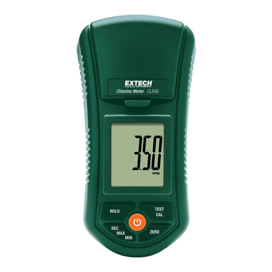
USER GUIDE
Free and Total Chlorine Tester
Patent Pending
Model CL500
800.561.8187
information@itm.com
www.
.com
Related Manuals for Extech Instruments CL500
Summary of Contents for Extech Instruments CL500
-
Page 1
USER GUIDE Free and Total Chlorine Tester Patent Pending Model CL500 800.561.8187 information@itm.com www. .com… -
Page 2: Meter Description
Meter Description CL500 Front Panel Description 1. Test Bottle Chamber 2. Test Bottle Chamber latch 3. LCD display 4. POWER button 5. HOLD button 6. REC‐MAX‐MIN button 7. ZERO button 8. TEST‐CAL button 9. Test bottle CL500-en-GB_V1.2 8/15 800.561.8187 information@itm.com www. .com…
-
Page 3: Getting Started
Getting Started Equipment Required A chlorine test requires a 10ml sample bottle, reagent powder for testing Free and Total chlorine, and the CL500 meter. Measurement Procedure Calibration considerations Ensure that the meter has been calibrated prior to use. Refer to the calibration section for this procedure. Test sample “Zero” measurement Note: Prior to testing, set the meter mode to FREE or TOTAL based on the desired test method. See Mode Selection. The meter should be in the OFF position. Place the test sample into the sample bottle up to the 10mL line (minimum). Place the cap on the bottle and tighten. Clean and dry the outside of the sample bottle to ensure a clean surface. Open the cover of the test chamber and insert the bottle completely into the chamber. Line up the white mark on the bottle with the white mark of the test chamber. Close the cover and lock it in place. Press the “POWER” button to turn the meter ON. The display will show ‘Free’ or ‘Total’ for 1 second and then ‘CAL0’. The meter is now ready for the “zero” test. Press the “Zero” button, the display will flash “tEST” and then “0.00”ppm. The Zero Test is now complete. Do not power down the meter. Measurement of Test Solution Open the test chamber and remove the test bottle. Add the required DPD powder (Free or Total) into the sample and then shake for 20 seconds until combined. Place the cap on the bottle and tighten. For the Free Chlorine test, use the Free Chlorine DPD powder For the Total Chlorine test, use the Total Chlorine DPD powder Clean and dry the outside of the sample bottle to ensure a clean surface. Wait 2 minute before placing the test bottle into the meter to allow time for the solution to mix thoroughly. Open the cover of the test chamber and insert the bottle completely into the chamber. Line up the white mark on the bottle with the white mark of the test chamber. CL500-en-GB_V1.2 8/15 800.561.8187 information@itm.com www. .com…
-
Page 4: Auto Power Off
Data Record (MAX/MIN Readings) 1. The Data record function records the MAX and Min readings. 2. Press «REC» button once to begin Data recording. The LCD will display the «REC» symbol. 3. To view the MAX value while in the recording mode press «REC» once. The display will show the maximum reading and “REC MAX» will show on the LCD display. 4. Press «REC» button once again and «REC MIN» will display on the LCD along with the minimum reading. 5. To erase the Max value and continue recording, while in the record mode, momentarily press the “Rec” button. The display will show “REC MAX”. Momentarily press the “HOLD” button, the display will now show “REC”. The Max value has been erased. 6. To erase the Min value and continue recording, while in the record mode, momentarily press the “Rec” button. The display will show “REC MAX”. Press the “REC” button once again and now the display will show “REC MIN”. Momentarily press the “HOLD” button, the display will now show “REC”. The Min value has been erased. 7. To exit Record mode, press the “REC” button for 3 seconds. The display will return to the current reading. Mode Selection – Free or Total The meter should be powered OFF. Press the «HOLD» and «REC» buttons simultaneously and then momentarily press the «Power» button. Press the «TEST» button to select the desired function (Free or Total) Chlorine. Press the «REC» button to confirm and save the selection into memory. Momentarily press the “Power” button to turn off the meter. Auto‐Power OFF The auto power off feature automatically switches the CL500 OFF 10 minutes after the last key press. CL500-en-GB_V1.2 8/15 800.561.8187 information@itm.com www. .com…
-
Page 5: Zero Calibration Procedure
5. Line up the white mark on the bottle with the white mark in the chamber and close the cover and latch it. 6. Press «CAL» once more and the display will flash “tEST” and show the following: 0.00 7. The meter is now ready for «zero chlorine» calibration. 8. Press «CAL» button once. The LCD will flash “CAL” for 10 seconds and will then show the following display: 0.00 9. The LCD will then display: 1.00 10. Zero Chlorine calibration is now complete. The meter is now ready for the 1.00 ppm Test solution calibration. CL500-en-GB_V1.2 8/15 800.561.8187 information@itm.com www. .com…
-
Page 6
1.00‐ppm Test solution calibration Clean the sides of the 1.00‐ppm Chlorine standard (Free or Total) solution bottle and insert it into the testing chamber. Line up the white mark on the bottle with the white mark in the chamber, close, and latch the cover. Press «CAL» once more; the display will flash “CAL” and then show the following: 1.00 When calibration is complete the LCD will return to the normal operating mode and measure the test solution. The display should show 1.00 ppm. The meter is now ready to measure test solutions. CL500-en-GB_V1.2 8/15 800.561.8187 information@itm.com www. .com… -
Page 7: Maintenance
Maintenance Low Battery Indication When the batteries become weak the “ ” icon will appear in the display. Refer to the battery replacement information below. Battery Replacement On the back of the meter, remove the 2 screws holding the battery cover in place. Replace the six (6) AAA batteries, observing polarity. Replace the battery compartment cover Battery Safety Reminders Never dispose of batteries in a fire. Batteries may explode or leak. Never mix battery types. Always install new batteries of the same type. Never dispose of used batteries or rechargeable batteries in household waste. As consumers, users are legally required to take used batteries to appropriate collection sites, the retail store where the batteries were purchased, or wherever batteries are sold. Disposal: Do not dispose of this instrument in household waste. The user is obligated to take end‐of‐life devices to a designated collection point for the disposal of electrical and electronic equipment. Electrode considerations The CL500 Chlorine Electrode arrives in a factory‐cleaned condition and is ready to be used. The electrode will perform best and yield more stable readings after the first few tests. Cleaning the Meter Occasionally wipe the meter housing with a damp cloth. Do not use abrasives or solvents. CL500-en-GB_V1.2 8/15 800.561.8187 information@itm.com www. .com…
-
Page 8: Specifications
Resolution 0.01 Accuracy 0.02 ppm@1.00 ppm Light Source LED, 525 nm Light Detector Photo Diode Response Time Less than 10 seconds Sample Volume 10mL minimum Sample Time Approximately 1 second Power Six 1.5 V batteries Power Consumption Stand‐By Mode: approx. 4mADC Testing Mode: approx. 12mADC Dimensions 155 x 76 x 62mm (6.1 x 3.0 x 2.4”); 320g (0.70lbs.) Auto Power OFF Automatically switches OFF 10 minutes after the last key press Method The measuring method is an adaptation of the USEPA method 330.5 and standard method 4500‐Cl G Copyright © 2014‐2015 FLIR Systems, Inc. All rights reserved including the right of reproduction in whole or in part in any form ISO‐9001 Certified www.extech.com CL500-en-GB_V1.2 8/15 800.561.8187 information@itm.com www. .com…
Page 1
Global Water OWNER’S MANUAL CL500 OnLine Residual Chlorine Monitor Global Water Instrumentation 11390 Ama
Page 2
4.0 Installation and Commissioning Prior to use for the first time, one of the reagents (the indicator) will have to be mixed. Refer to section 10.2
Page 3 — Table of Contents
4.2 Plumbing The recommended plumbing for the instrument is shown in Figure 4. The instrument is designed to require very little head pressure to ope
Page 4
The fluid waste from drain connection of this instrument contains reagents diluted with large quantities of sample water. Global Water Instrumentation
Page 5 — Specifications
Plugs are inserted into the RS-485 and 4-20mA cable bulkheads when shipped, to ensure a watertight seal. These plugs should be removed and discarded w
Page 6 — 1.0 Overview
CL500 (2/08) Page 10 REV 2.0 4.3.3 Relays The Alarm 1 and Alarm 2 relays are mechanical relays rated at 240 VAC 2A. Please note that the relays are
Page 7
5.0 Operation The CL500 Online Chlorine Analyzer allows for the measurement of the chlorine of process water on-line. The chlorine value of the proce
Page 8
5.2 Security Access Feature The instrument is equipped with a security access code feature that can be activated in the configuration mode. If the
Page 9 — 3.0 Theory of Operation
6.0 Instrument Calibration The instrument was tested prior to leaving the factory. Since it operates from a pre-determined calibration curve, no cali
Page 10
6.2 Zero (offset) Calibration Procedure Generally this calibration is only required if readings are expected to be below 1 mg/L or if it is required
Page 11
7.0 Instrument Configuration (CONFIG mode)The instrument has been designed to provide the ability to customize the instrument according to needs at
Page 13
The next prompt will be the chlorine level assigned to the 20MA. Select the chlorine level using the S and T buttons. Once the desired level has been
Page 14
Press the button to continue on and select the desired instrument address using the S or T buttons. Once the selection is satisfactory, press the
Page 15 — 5.0 Operation
Alarm 1 Set Point: This prompt is used to select the set point for this alarm; this is indicated by “S/P” shown on the lower row of the display. Sele
Page 16 — button
7.7 Speed of Response The speed of response for both displayed and output values of mg/L can be adjusted in this menu. Although the default setting i
Page 17
7.9 RS-485 Parameters These menus will only appear if the RS-485 is enabled (see 7.3). The default is 8 Bit, no (nOnE) Parity, 1 Stop Bit. Make selec
Page 18
CL500 (2/08) Page 21 REV 2.0 8.0 Additional Features and Options 8.1 Backlit LCD The backlit LCD allows for easier readability of the LCD dis
Page 19 — ↵ button
CL500 (2/08) Page 22 REV 2.0 8.2.3 Modbus Communication Modbus protocol communication manual is available Cat. #24569GW. This manual is available
Page 20
CL500 (2/08) Page 23 REV 2.0 9.0 Troubleshooting 9.1 CL500 Fault Detection The CL500 performs continuous diagnostic monitoring. In the CL500, t
Page 21
CL500 (2/08) Page 24 REV 2.0 A level 1 fault is a system fault. This is NOT a problem that the operator can correct, and the unit must be returned
Page 22
CL500 (2/08) Page 25 REV 2.0 9.4 Diagnostic Chart Symptom Cause Cure Lower display shows MA 4-20 mA loop open Check wiring. See sections 4.3.4 a
Page 23
Table of Contents Section Page Specifications…
Page 24
10.0 Routine Maintenance 10.1 Maintenance Schedule The recommended schedule is shown below. It is important to replace the reagents on a monthly
Page 25
After a PRIME the CL500 will perform a water calibration (WCAL). It will take a few minutes to complete this procedure. 3 Month Tubing Replacemen
Page 26
INLETCHECKVALVESCAP ASSEMBLY «A»PUMPHAMMERAND SPRINGTHUMBSCREWREAGENTPUMPASSYINLETOUTLETFLOW`CHECK VALVE DETAILOPTICS SYSTEMKNURLED TOPC
Page 27 — 9.0 Troubleshooting
Indicator Reagent Preparation Add about 400 ml of deionized water into the indicator bottle. Cap tightly and shake vigorously until the powder is diss
Page 28
CL500 (2/08) Page 30 REV 2.0 10.5 Cleaning the CL500 Flush the system as mentioned in section 10.1 Maintenance Schedule. When the flushing is fin
Page 29 — Symptom Cause Cure
CL500 (2/08) Page 31 REV 2.0 11.0 Accessories and Replacement Parts List The items shown below are recommended accessories and replacement parts. A
Page 30 — 10.0 Routine Maintenance
CL500 (2/08) Page 32 REV 2.0 12.0 Warranty Global Water Instrumentation., as vendor, warrants to the original purchaser of this instrument that it
Page 31
Table of Contents (continued) Section Page 7.7 Speed of Response…
Page 32 — and the indicator
CL500 (2/08) Page 1 REV 2.0 Specifications Measurement Range 0 – 10.00 mg/L (PPM) Accuracy ±5% of reading or ±0.03 mg/L (PPM) whichever is greater f
Page 33
CL500 (2/08) Page 2 REV 2.0 1.0 Overview The CL500 Online Chlorine Analyzer allows for the reading of chlorine levels of process water on-line. The
Page 34
1.2 The Display Figure 1 illustrates all the items that can appear on the display. The upper row of the display (1) is used for reporting the chlor
Page 35 — Accessory Catalog Number
2.0 Safety This manual contains basic instructions that must be followed during the commissioning, operation, care and maintenance of the instrument
Page 36 — 12.0 Warranty
CL500 (2/08) Page 5 REV 2.0 3.0 Theory of Operation The CL500 has two solenoid valves, one for sample water (FLOW) and one for draining of the cuve

CL- 500 – высокоскоростной автоматизированный анализатор мочи.
Производительность: 500 анализов в час.
Тесты: Уробилиноген, Билирубин, Кетоны, Эритроциты, Белок, Нитриты, Лейкоциты, Глюкоза, Удельная плотность, pH, Аскорбиновая кислота, Креатинин, Кальций, Микроальбумин.
Процесс анализа предельно прост.
Вы опускаете тест-полоску в мочу и кладете ее на устройство автоподачи.
С этого момента прибор работает самостоятельно:
— автоматически определяет наличие полоски на автоподатчике;
— доставляет ее к устройству считывания в правильной позиции;
— производит считывание;
— сбрасывает отработанную тест-полоску в контейнер для отходов.
Принтер: встроенный;
Интерфейс: RS-232, параллельный порт;
Память: 5000 результатов;
Размеры: 39 x 29 x 34 см;
Вес: 6,5 кг.
Инструкции
Регистрационное Удостоверение
Global Water
MODBUS MANUAL
For the
CL500
Online Residual
Chlorine Monitor
Global Water
11390 Amalgam Way
Gold River CA 95670
Phone: 800-876-1172
Fax: 847-672-9988 EMail:Globalw@globalw.com Website: www.globalw.com
Revised (3/09)
Rev. 1.3
1.0Overview
The Global Water CL500 uses a communication protocol called Modbus. A company called Modicon, for use with their programmable controllers, developed the Modbus protocol. Since that time Modbus has evolved into common communication protocol in industry.
The communication method involves using a master-slave technique, in which there is one master and several slaves. The CL500 is a slave device. Only the master can initiate queries. These queries are directed to an individual slave device and the appropriate slave responds with the requested data.
A broadcast message can be sent to all slaves. The slave devices do not answer these broadcasts.
There are two transmission modes. These modes are known as RTU (Remote Terminal Unit) and ASCII (American Standard Code for Information Interchange).
The CL500 can be setup in a network of up to 255 slave devices. Each device must have a different address (1-255). The CL500 can be set for either RTU or ASCII mode.
|
CL500 Modbus (3/09) |
1 |
|
Rev. 1.3 |

2.0Electrical Connections
All of the electrical connections to the instrument are made at the termination area, which is located on the portion of the instrument. The connections are labeled and are selfdescriptive (see Figure 1). Please follow all local and government recommendations and methods for installation of electrical connections to and between the instrument and other peripheral devices.
Plugs are inserted into cable bulkheads when shipped, to ensure a watertight seal. These plugs should be removed and discarded as required when cabling to this connection.
The bulkhead will accept cable diameters from 5.8mm (.230 in.) up to 10 mm (.395 in.). The terminals are designed to accept wires in the range of 14-28 AWG. All wires should be stripped to a length of 6 mm
It is the user’s responsibility to assure that the watertight seal is maintained after the terminal box has been wired for operation. If any of the bulkheads are not tightened properly around a cable or plug, the ratings of the instrument will be jeopardized and there is a possibility of creating a shock hazard.
Note: Only qualified electricians should be allowed to perform the installation of the instrument as it involves a line voltage that could endanger life.
|
Captive Screw |
||
|
High Voltage Cover |
||
|
Power Cable |
Power |
|
|
Terminal |
||
|
Strain Relief |
Block |
|
|
Anchor |
Alarm #2 |
|
|
Power |
Terminal |
|
|
Bulkhead |
Block |
|
|
Alarms |
Alarm #1 |
|
|
Terminal |
||
|
Bulkhead |
||
|
Block |
||
|
Communication |
RS-485 |
|
|
Bulkhead |
||
|
Terminal |
||
|
Block |
||
|
4-20mA |
||
|
Terminal |
||
|
Block |
Figure 1: Electrical Connections for the Instrument
|
CL500 Modbus (3/09) |
2 |
|
Rev. 1.3 |
2.1 RS-485 Connection
The RS-485 half-duplex (2-wire) digital interface operates with differential levels that are not susceptible to electrical interferences. This is why cable lengths up to 3000 ft can be implemented. The last device on every bus may require a 120-ohm termination resistor to eliminate the possibilities of signal reflection on the line. Do not run RS-485 cables in the same conduit as power.
Ensure each instrument is not powered when connecting the RS-485 line. To prevent damage to the instrument, ensure that power is disconnected prior to making connections.
|
CL500 Modbus (3/09) |
3 |
|
Rev. 1.3 |
 Loading…