- Manuals
- Brands
- Arctic Cat Manuals
- Offroad Vehicle
- 650 Twin2004
- Service manual
-
Contents
-
Table of Contents
-
Troubleshooting
-
Bookmarks
Related Manuals for Arctic Cat 650 Twin2004
Summary of Contents for Arctic Cat 650 Twin2004
-
Page 1
2004 2004 650 Twin RC C C ®… -
Page 2
Such efficiency not only helps build consumer confidence but also saves time and labor. All Arctic Cat ATV publications and decals display the words Warning, Caution, Note, and At This Point to emphasize important information. The symbol ! WARNING identifies personal safety-related information. Be sure to fol- low the directive because it deals with the possibility of severe personal injury or even death. -
Page 3
TABLE OF CONTENTS Section General Information Periodic Maintenance/Tune-Up 3. Engine/Transmission Fuel/Lubrication/Cooling Electrical System Drive System Suspension 8. Steering/Frame Controls/Indicators 10. Aids for Maintenance 11. Troubleshooting… -
Page 4: Table Of Contents
SECTION 1 — GENERAL INFORMATION TABLE OF CONTENTS General Specifications ……….1-2 Break-In Procedure ……….1-3 Gasoline — Oil — Lubricant ……..1-3 Genuine Parts …………1-4 Preparation For Storage………. 1-5 Preparation After Storage……..1-5…
-
Page 5: General Specifications
General Specifications* CHASSIS CARBURETOR Dry Weight (approx) 293 kg (646 lb) Type Keihin CVKR-D32 (2) Length (overall) 205 cm (81 in.) Main Jet 122 — Front 122 — Rear Height (overall) 125 cm (49.3 in.) Slow Jet Width (overall) 120.7 cm (47.5 in.) Pilot Screw Setting (turns) 2 1/2 Suspension Travel (front)
-
Page 6: Break-In Procedure
! CAUTION reached normal operating temperature. Do not idle the engine for excessively long periods of time. Do not use white gas. Only Arctic Cat approved gasoline additives should be used. During the break-in period, a maximum of 1/2 throttle is recommended;…
-
Page 7: Genuine Parts
The recommended lubricant is Arctic Cat Gear Lube (p/n 0436-007) or an equivalent gear lube which is SAE approved 80W-90 hypoid. This lubricant meets all of the lubrication requirements of the Arctic Cat ATV front differentials and rear drives. ! CAUTION…
-
Page 8: Preparation For Storage
3. Check all control wires and cables for signs of the air filter housing cover and air filter. Start the wear or fraying. Replace if necessary. engine and allow it to idle; then using Arctic Cat Engine Storage Preserver (p/n 0636-177), rapidly 4. Change the engine/transmission oil and filter.
-
Page 9
NOTES… -
Page 10
SECTION 2 — PERIODIC MAINTENANCE/TUNE-UP TABLE OF CONTENTS Periodic Maintenance Chart……..2-2 Lubrication Points………… 2-3 Battery…………..2-3 Fuses …………..2-4 Air Cleaner/Filter …………. 2-4 Valve/Tappet Clearance (Feeler Gauge Procedure) ……..2-6 Valve/Tappet Clearance (Valve Adjuster Procedure) ……… 2-7 Testing Engine Compression ……..2-7 Spark Plugs…………. -
Page 11: Periodic Maintenance Chart
A = Adjust I = Inspect C = Clean L = Lubricate Periodic Maintenance D = Drain R = Replace Chart Every Month Every 3 Initial Service Every 6 Every Year or Months or After Break-In Every Months or Item Every 1500 As Needed (First Mo or…
-
Page 12: Lubrication Points
Lubrication Points It is advisable to lubricate certain components periodi- cally to ensure free movement. Apply light oil to the components using the following list as reference. A. Throttle Lever Pivot/Cable Ends B. Brake Lever Pivot C. Auxiliary Brake Pedal Pivot ChargTim D.
-
Page 13: Fuses
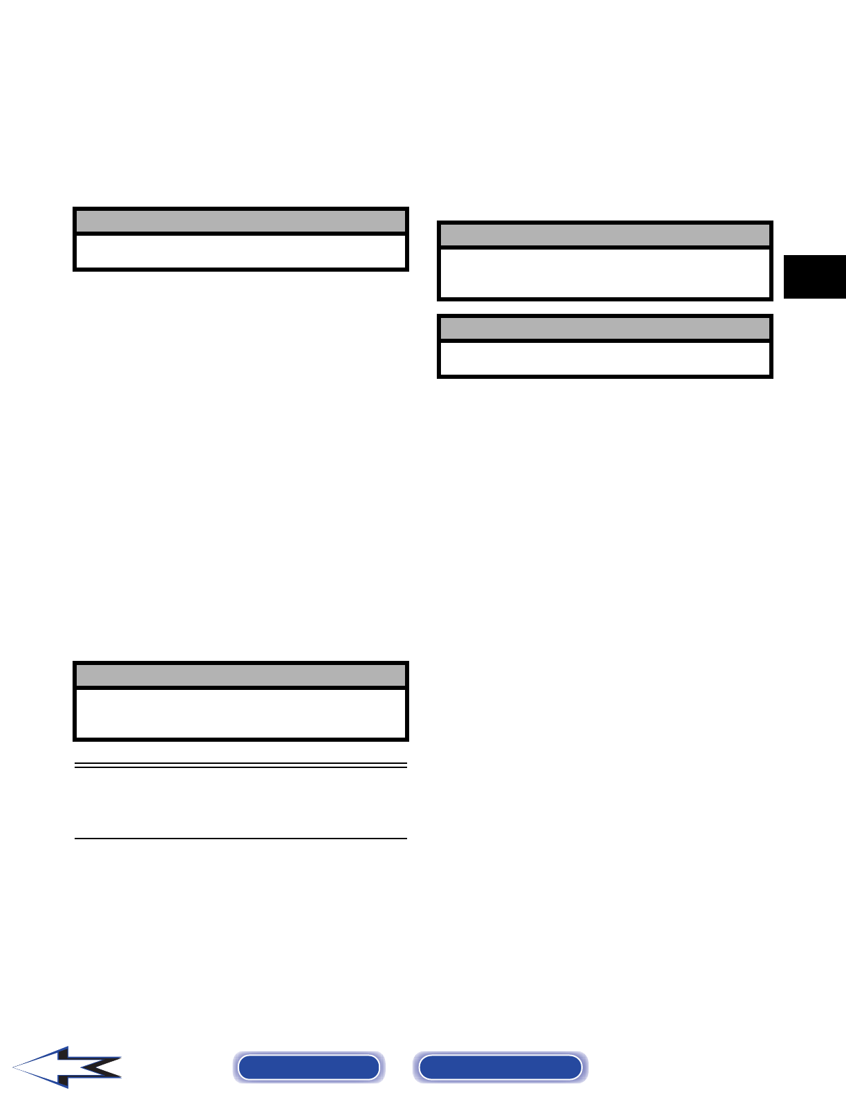
3. Remove the vent plugs; then (if necessary) fill the NOTE: To remove the fuse, compress the locking battery with distilled water to the upper level tabs on either side of the fuse cover and lift off. indicated on the battery. 4.
-
Page 14
NOTE: Foam Filter Cleaner (p/n 0436-194) and Foam Filter Oil (p/n 0436-195) are available from Arctic Cat. 5. Dry the filter. 6. Put the filter in a plastic bag; then pour in air filter oil and work the filter. Reattach the filter to the frame. -
Page 15: Valve/Tappet Clearance (Feeler Gauge Procedure)
3. Wipe any accumulation of oil or gas from the filter housing and one-way drains. Valve/Tappet Clearance (Feeler Gauge Procedure) To check and adjust valve/tappet clearance, use the following procedure. KX227 NOTE: The seat, air filter housing, front fenders, ! CAUTION front inner covers, and side panels must be removed for this procedure.
-
Page 16: Valve/Tappet Clearance (Valve Adjuster Procedure)
8. Rotate the crankshaft counterclockwise until the TR mark aligns in the timing hole; then repeat Valve/Tappet Clearance steps 3-7 for the rear cylinder. (Valve Adjuster Procedure) 9. Install the timing inspection plug; then install the four tappet covers and tighten securely. To check and adjust valve/tappet clearance, use the 10.
-
Page 17: Spark Plugs
7. If compression is abnormally low, inspect the following items. A. Verify starter cranks engine over. B. Gauge is functioning properly. C. Throttle lever in the full-open position. D. Valve/tappet clearance correct. E. Valve bent or burned. F. Valve seat burned. ATV0052B …
-
Page 18: Gas/Vent Hoses
3. Tighten the jam nut against the throttle cable adjuster securely; then slide the rubber boot over Gas/Vent Hoses the adjuster. Replace the gas hose every two years. Damage from aging may not always be visible. Do not bend or Adjusting Engine RPM obstruct the routing of the carburetor vent hose.
-
Page 19: Front Differential/Rear Drive Lubricant
7. Start the engine (while the ATV is outside on level ground) and allow it to idle for a few minutes. 8. Turn the engine off and wait approximately one minute. 9. Unscrew the oil level stick and wipe it with a clean cloth.
-
Page 20: Tires
0736-568 KX395A 4. After all the oil has been drained, install the drain plugs and tighten to 0.5 kg-m (3.5 ft-lb). 5. Pour the appropriate amount of recommended oil into each filler hole. 6. Install the filler plugs. Tighten to 2.2 kg-m (16 ft-lb).
-
Page 21: Steering Components
Steering Components Nuts/Bolts/Cap Screws The following steering components should be Tighten all nuts, bolts, and cap screws. Make sure riv- inspected periodically to ensure safe and proper opera- ets holding components together are tight. Replace all tion. loose rivets. Care must be taken that all calibrated nuts, bolts, and cap screws are tightened to specifica- A.
-
Page 22: Switches
TAILLIGHT-BRAKELIGHT To replace the taillight-brakelight bulb, use the follow- ing procedure. 1. Remove the two screws and remove the lens cover. 2. Push the bulb in and turn it counterclockwise. 3. Install the new bulb by turning it clockwise while pushing in.
-
Page 23
Stop the ATV completely and shift the transmission If the reverse lever light does not illuminate when into the R position. The reverse gear indicator light shifted to the reverse position, the switch may be should be illuminated. faulty, the fuse may be blown, the bulb may be faulty, a connection may be loose or corroded, or the lever may need adjusting. -
Page 24: Speedometer/Indicator Lights
7. Rotate the shift rod end as necessary to align its 6. 4WD Indicator — Displays 4WD when the front threaded shaft with the hole in the shifter arm. drive selector switch is moved to the 4WD posi- Secure with a new lock nut (B). Tighten securely. tion.
-
Page 25: Frame/Welds/Racks
14. Mode Button — Used (in conjunction with the Odometer/Trip Meters/Hour Meter) to shift the odometer/trip meters/hour meter display through the four modes: odometer, trip meter (A), trip meter (B), and hour meter. Frame/Welds/Racks The frame, welds, and racks should be checked period- CD091 ically for damage, bends, cracks, deterioration, broken 2.
-
Page 26
730-434B AF739DB NOTE: During the bleeding procedure, watch the 3. If thickness of either brake pad is less than 3.2 mm reservoir sight glass very closely to make sure (0.125 in.), the brake pads must be replaced. there is always a sufficient amount of brake fluid. When the sight glass changes from dark to light, … -
Page 27: Burnishing Brake Pads
E. Install the wheel. Tighten to 5.5 kg-m (40 ft-lb). 5. Burnish the brake pads (see Burnishing Brake Pads in this section). Burnishing Brake Pads All brake pads must be burnished to achieve full brak- AN604D ing effectiveness. Braking distance will be extended until brake pads are properly burnished.
-
Page 28
REMOVING 4. Remove the drive clutch cap screw (C) (left-hand threads) and account for two washers and a 1. Make sure that the ignition switch is in the off stepped washer. position; then remove the clamps (A) and air duct (B). -
Page 29
2. If belt width is below the service limit of 28.8 mm (1.13 in.) or there is damage to the belt, it must be replaced. INSTALLING NOTE: Be sure to install the belt in the same direction as originally installed. When installing a new belt, direct the top of the lettering (A) toward the engine. -
Page 30
SECTION 3 — ENGINE/TRANSMISSION TABLE OF CONTENTS Engine/Transmission ……….3-2 Specifications …………3-2 Table of Contents ………… 3-3… -
Page 31
11.973-11.984 mm (0.4714-0.4718 in.) removed from the frame. Diameter Cylinder Head Distortion (max) 0.05 mm (0.002 in.) NOTE: Arctic Cat recommends the use of new Cylinder Head Cover (max) 0.05 mm (0.002 in.) Distortion gaskets, lock nuts, and seals and lubricating all… -
Page 32
3. Disconnect the wiring on the starter relay; then disconnect the CDI unit and the engine brake Table of Contents actuator control connectors. Removing Engine/Transmission ……3-3 Left-Side Components ……….3-6 Removing Left-Side Components ……3-6 Right-Side Components ………. 3-8 Removing Right-Side Components…… -
Page 33
11. Remove the front and rear spark plug caps; then remove the oil pressure sending unit lead (I). KX101A 8. Remove the rear V-belt cooling boot; then disconnect the belt failure detection lead (D) and KX046A the engine brake control actuator lead (C). 12. -
Page 34
KX136 KX126 15. Lift the carburetors above the frame and tie to the 18. Remove the front exhaust pipe accounting for the handlebar; then cover the carburetor openings with ring gasket. duct tape or other suitable material. KX067 KX121 19. Remove the two upper coolant hoses and the breather hose;… -
Page 35: Left-Side Components
20. Remove the rear engine mount through-bolt; then remove the rear engine mount brackets from the Left-Side Components frame. NOTE: Removing the brackets will allow the engine to be moved rearward enough to release the front drive coupler. NOTE: For efficiency, it is preferable to remove and disassemble only those components which need to be addressed and to service only those…
-
Page 36
3. Remove the V-belt cover (See Removing Right-Side Components); then remove the three clutch cover bolts (B) noting the arrow (D) and attach the clutch holding tool (A). KX239 7. Remove the ball bearing; then thread the flywheel puller (A) into the rotor/flywheel. KX236A 4. -
Page 37: Right-Side Components
Removing Right-Side Components A. V-Belt Cover B. Driven Pulley C. Clutch Assembly ! WARNING KX242 Imbalance of clutch or driven pulley or excessive 11. Remove the cap screws securing the oil pump (A); RPM could cause component failure resulting in then remove the oil pump drive chain (B) and oil severe injury or death.
-
Page 38: Top-Side Components
KX138A KX232A 4. Remove the V-belt cover accounting for the seal. 6. Hold the driven pulley with an appropriate holder; Note the position of the glue joint (A). then remove the driven pulley nut and the driven pulley. ATV2064 KX246A 5.
-
Page 39: Removing Top-Side Components
Removing Top-Side Components A. Valve Covers B. Cylinder Heads NOTE: Remove the spark plugs and timing inspection plug (A); then using the recoil starter, rotate the crankshaft to top-dead-center (TDC) of ATV2065 the compression stroke of the front cylinder. TF is top-dead-center front.
-
Page 40
KX248 KX250A 9. Remove the front cylinder head assembly and ! CAUTION account for two alignment pins (A), cylinder head This is a ratchet-type chain tensioner and must gasket (B), oil pipe (C), and camshaft chain guides be completely removed and reset if the mounting (D). -
Page 41
KX252 KX253 13. Hold the intermediate shaft (A) with an Allen 16. Remove the cylinder bolts (B); then remove the wrench. cylinder (A). Account for the base gasket (C) and alignment pins (D). KX253 KX256A 14. Remove the intermediate shaft sprocket nut (A); then remove the sprocket (B), drive chain (C), and the rear camshaft drive chain (D). -
Page 42: Center Crankcase Components
18. Using a piston pin puller (A), remove the piston pins (B); then remove the pistons from the connecting rods. KX258 2. Remove the shift shaft positioning bolt (A) ATV2068 accounting for a washer, spring, and ball; then remove the left crankcase bolts (B = 6 mm) (C = 8 mm).
-
Page 43: Disassembling Crankcase Half
NOTE: Connecting rod cap should be immedi- ately installed on its connecting rod to prevent a Disassembling mismatch. Crankcase Half 3. Remove the three cap screws (A); then remove the shift shaft cover (B). 1. Using a press, remove the crankshaft from the right case;…
-
Page 44
KX266 KX269 7. Remove the spacer (A), idler gear assembly (B), 9. Check angle (A) for shift fork bending. It must be and washers and spacer (C); then remove low and 90°. high range gears (D). ATV2069 KX267 10. Measure the thickness of the shift fork at (A); then 8. -
Page 45
KX271 KX274 2. Remove circlip (A); then remove the output drive idler gear (B). KX275A NOTE: Check the bevel gears (A) for scoring, chipping, or abnormal gear patterns; then check KX272 the bearings by rotating the drive and driven 3. -
Page 46: Servicing Components
2. Place the valve cover on the Surface Plate (p/n NOTE: For disassembling and servicing, refer to 0644-016) covered with #400 grit wet-or-dry Servicing Center Crankcase Components, this sandpaper. Using light pressure, move the valve section. cover in a figure eight motion. Inspect the sealing surface for any indication of high spots.
-
Page 47
Measuring Valve Face/Seat Width 2. Remove the valve seal and the lower remaining spring seat. Discard the valve seal. 1. Using a micrometer, measure the width of the valve face. CC136D NOTE: The valve seals must be replaced. ATV-1004 2. -
Page 48
2. Using the Standard Valve Guide Reamer (p/n 0444-017), remove any burrs or tight areas from the valve guide journals. CC131D 3. Push the valve from side to side; then from top to bottom. CC142D 4. Maximum “wobble” deflection must not exceed specifications. -
Page 49
Valve Seat/Guide Servicing Flow 2. Insert an intake valve seat pilot shaft into one of the intake valve guides. Slide the intake valve seat Chart grinding tool onto the pilot shaft; then using light pressure on a driver handle and a deep socket, grind intake valve… -
Page 50: Piston Assembly
Installing Valves Cleaning/Inspecting Piston 1. Apply grease to the inside surface of the valve 1. Using a non-metallic carbon removal tool, remove seals; then place a lower spring seat and valve any carbon buildup from the dome of the piston. guide seal over each valve guide.
-
Page 51
Cleaning/Inspecting Piston Rings 2. Insert an inside dial indicator into the piston-pin bore. The diameter must not exceed specifications. Take two measurements to ensure accuracy. 1. Take an old piston ring and snap it into two pieces; then grind the end of the old ring to a 45° angle and to a sharp edge. -
Page 52: Cylinder/Cylinder Head Assembly
3. Place the cylinder head on the surface plate covered with #400 grit wet-or-dry sandpaper. Using light pressure, move the cylinder head in a figure eight motion. Inspect the sealing surface for any indication of high spots. A high spot can be noted by a bright metallic finish.
-
Page 53
2. Inspect the cylinder for pitting, scoring, scuffing, warpage, and corrosion. If marks are found, repair the surface using a cylinder hone (see Honing Cylinder in this sub-section). 3. Place the cylinder on the surface plate covered with #400 grit wet-or-dry sandpaper. Using light pressure, move the cylinder in a figure eight motion. -
Page 54
CC283D CC005D 2. Rotate the camshaft and note runout; maximum 2. Place a strip of plastigauge in each of the camshaft tolerance must not exceed specifications. lands in the cylinder head. 3. Place the valve cover on the cylinder head and Measuring Camshaft Lobe Height secure with the valve cover cap screws. -
Page 55: Servicing Left-Side Components
CC145D KX279 6. If clearance is excessive, measure the journals of the camshaft. Servicing Left-Side NOTE: If the journals are worn, replace the cam- shaft; then measure the clearance again. If it is still Components our of tolerance, replace the cylinder head. Inspecting Automatic Compression Release RECOIL STARTER…
-
Page 56
CD047 KX282 2. Place the driven pulley assembly onto the 6. Wipe out excessive grease; then using a standard compressor tool base engaging the dowel pins into tip screwdriver (B), dislodge the four guide pins appropriate holes in the fixed face of the assembly. (A). -
Page 57: Drive Clutch Assembly
CD060 CD058 4. Install the spring seat (C), spring (D), spring seat 4. Inspect the pins and bushings for wear, flat spots, (E), and circlip (F); then attach the spring holder looseness, or cracking. (B) and tighten nut (A) until the circlip (F) can be installed.
-
Page 58
Inspecting ! WARNING Inspect all rotating parts carefully for cracks, loose bolts, chips, or nicks. Clutches and driven pulleys rotate at high speeds and can break up with explo- sive force causing severe injury or death. 1. Inspect the sheave faces (A) for cracks, galling, or hollowing;… -
Page 59
KX291 KX294 3. Inspect the ramp weights (A) and pins (B) in the 2. Place the fixed sheave on the clutch holder; then movable sheave. Replace any worn parts. install the movable sheave, spider (A) and shoes (B) aligning the arrow (C) with the arrow (D) on the movable sheave. -
Page 60: Servicing Center Crankcase Components
ATV2072 KX297 4. Measure the crank pin diameter (A) and check the crankshaft marking (B). If no mark is on the crankshaft, the crank pin diameter should be 39.984-39.992 mm (1.5742-1.5745 in.). If the crankshaft is marked with “O,” crank pin diameter Servicing Center should be 39.993-40.000 mm (1.5745-1.5748 in.).
-
Page 61: Disassembling Output Drive Bevel Gear Assembly
DISASSEMBLING OUTPUT DRIVE 7. Slowly turn the crankshaft and note the readings at the points indicated. Crankshaft runout must be BEVEL GEAR ASSEMBLY less than 0.10 mm (0.0039 in.). AT THIS POINT If no abnormal wear, chipping, or bearing roughness is found, proceed to Installing Output Drive/Driven Bevel Gears in this sub-section.
-
Page 62: Disassembling Output Driven Bevel Gear Assembly
3. Loosen the bevel gear (B) using an Allen wrench while holding the housing (A) in a vise; then continue to turn the bevel gear (about 4-5 turns) until the internal nut is free of the holder bolts. KX302 KX299 4.
-
Page 63: Assembling Crankcase Half
ATV2080 KX308 4. Hold the housing assembly (A) with the output shaft holder (B) and spacer (C) in a vise; then remove the oil seal (D). KX309 KX306 5. Using a special deep socket (B), remove the output Assembling Crankcase shaft retainer nut (A).
-
Page 64
KX310 ATV2081 3. Install the rear cylinder camshaft chain guide (A) 6. Select connecting rod big end inserts using the and tighten bolt (B) to 2.0 kg-m (14.5 ft-lb). following chart and the markings on the crankshaft and connecting rod. Big End Bearing Insert Selection Con-Rod Big End Crank Pin… -
Page 65
ATV2074A KX313 7. Install the inserts into the connecting rods and 10. Install the crankshaft assembly in the right caps; then use plastigauge (A) to measure crankcase half. connecting rod/crankshaft clearance (B). Tighten 11. Using a press, install the driven shaft in the the connecting rod nuts to 3.5 kg-m (25 ft-lb). -
Page 66
KX319A KX316 16. Apply molybdenum disulfide oil to the shift shaft 14. Apply clean engine oil to the shift rod (A), shift (A); then install the shift spring (C) and guide (D). fork (B), and needle bearing (C); then install the Apply red Loctite #271 to the shift shaft spring shift rod with shifter, spacer (D), and needle bolt (B) and tighten to 2.5 kg-m (18 ft-lb). -
Page 67: Joining Crankcase Halves
Joining Crankcase Halves A. Breather Tube B. Positioning Bolt C. Drive Bevel Gear (Assembling) D. Driven Bevel Gear (Assembling) E. Drive/Driven Bevel Gears ATV2085 (Installing) 3. Install the breather tube (A) on the crankcase fitting aligning the white line on the tube with the F.
-
Page 68
KX322 KX325A 7. Place the bearing housing into the holding fixture; 10. Using the bearing driver (A), drive the bearing then apply blue Loctite #242 on the threads of the into the housing until it bottoms out. bearing retainer (A). Install with the dished side (B) directed away from the bearing and tighten to 12 kg-m (87 ft-lb). -
Page 69
KX328 KX331A 14. Apply grease to the output drive oil seal; then 17. Install the driven gear assembly (B) in the install in the housing being careful not to damage crankcase; then tighten the four cap screws (A) to the lip of the seal or distort the seal. 2.7 kg-m (19.5 ft-lb). -
Page 70
NOTE: To decrease backlash, decrease the thick- ness of shims (7). To increase backlash, increase the thickness of shims (7). Make small changes at a time. 1. Ball Bearings 2. Drive Bevel Gear Shims 3. Output Drive Bevel Gear 4. -
Page 71
NOTE: The following illustration indicates that the drive gear is running too deep in the set. Increase drive housing shims and decrease driven housing shims. ATV2089 22. Increase or decrease shim thickness on the drive bevel gear housing until the correct contact pattern is obtained. -
Page 72
KX339 KX336 29. Install the position plate (A); then tighten cap 26. Align the punch mark (B) on the intermediate screws (B) to 0.9 kg-m (78 in.-lb). shaft sprocket (A) with the index mark (C) on the crankcase. KX340 KX337 30. -
Page 73: Installing Right-Side Components
32. To prepare the intermediate shaft chain tensioner (A) for installation, release the stopper (B); then Installing Right Side push the rod (C) into the housing and secure with a piece of wire (D). Components 1. Install the driven pulley on the transmission driven shaft (A) being careful not to jam the splines (B) with the splines in the pulley (C).
-
Page 74: Installing Left-Side Components
KX348A KX350A 3. Loop the belt over the driven pulley; then install 2. Make sure that alignment pins (A) are in place and the drive clutch with holding tool (A) with cap apply clean engine oil to oil port (B). screws (B) referenced to the arrow (D) and tighten the cap screw (C) (left-hand threads) to 9.5 kg-m (69 ft-lb).
-
Page 75
5. Apply grease to the O-ring (A); then install the pin (B), spring (C), and oil pump chain tensioner bolt (D) and tighten to 2.5 kg-m (18 ft-lb). KX355 9. Install the starter clutch gear (C) and torque limiter (A); then wipe the crankshaft and rotor/flywheel mating surfaces clean… -
Page 76: Installing Top-Side Components
KX359 KX358 12. Install a new O-ring (A) in the collar (B); then apply grease to the O-ring and install the collar into the alternator cover. Installing Top-Side Components A. Piston B. Cylinder C. Cylinder Heads D. Camshafts NOTE: If the piston rings were removed, install them in this sequence.
-
Page 77
3. Apply clean engine oil to the piston skirts and cylinder walls; then install the cylinders and clamp (A) (rear only) and tighten the cylinder cap screws (B) to 1.0 kg-m (87 in.-lb). Install the cam chain guide (C) and the oil pipe (D). ATV2098 ! CAUTION Incorrect installation of the piston rings will… -
Page 78
ATV2101 KX364 7. Install the rear camshaft (A) identified by the 10. Install pin (A), spring (B), washer (C), and chain groove (B). tensioner cap bolt (D); then tighten cap bolt to 2.2 kg-m (16 ft-lb). KX363 KX365 8. Direct the arrow (A) of the rear camshaft upward (left side view);… -
Page 79: Installing Engine/Transmission
270° and align the “TF” mark (A) with the notch (B) in the inspection window. ATV2107 Installing Engine/Transmission NOTE: Arctic Cat recommends that new gaskets and O-rings be installed whenever servicing the ATV. ATV2106 1. Using suitable lifting…
-
Page 80
KX078A KX089B 2. Raise the front of the engine/transmission sufficiently to enable the front drive coupler to engage the front output shaft; then lower the front of the engine/transmission and engage the coupler. Slide the boot over the yoke. KX069A 5. -
Page 81
10. Remove the tape or caps from the intake hoses checking for any dirt, hardware items, or liquids; then install the carburetors into the intake hoses and tighten the clamps securely. Make sure the carburetors are securely seated by rocking side to side after installation. -
Page 82
16. Connect the speed sensor, forward/reverse sensor lead, and oil pressure warning lead; then connect the drive belt failure detector lead and the engine brake control servo lead to the main harness. Connect the spark plug wires. 17. Remove the tape from the carburetor inlets checking for any foreign material;… -
Page 83
NOTES 3-54… -
Page 84
SECTION 4 — FUEL/LUBRICATION/COOLING TABLE OF CONTENTS Carburetor Specifications ……..4-2 Carburetor Schematic ……….4-2 Carburetor …………… 4-3 Cleaning and Inspecting Carburetor……4-6 Throttle Cable Free-Play ……… 4-8 Engine RPM (Idle)……….. 4-8 Gas Tank …………..4-9 Gas Tank Valve …………4-9 Gas/Vent Hoses ………… -
Page 85: Carburetor Specifications
Carburetor Specifications ITEM Type Keihin CVKR-D32 (2) Main Jet 122 (Front)/122 (Rear) Slow Jet Pilot Screw Setting 2 1/2 (turns) Needle Jet 3.6 #3 Jet Needle BZL-2.470 Idle RPM 1050-1150 Float Arm Height 3-5 mm (0.12-0.20 in.) Throttle Cable Free-Play 3-6 mm (at lever) (1/8-1/4 in.)
-
Page 86: Carburetor
Carburetor ! WARNING Whenever any maintenance or inspection is per- formed on the fuel system during which there may be fuel leakage, there should be no welding, smok- ing, open flames, etc., in the area. TROUBLESHOOTING KX025E 1. Drain float bowls into a clean, clear container. 8.
-
Page 87
8. Loosen the outer jam nut securing the throttle cable to the carburetor body; then route the cable out of the way. KX118 KX137 9. Remove the Phillips-head screws holding the cable end plates (A); then pull out the starter plungers and set aside. -
Page 88
KX369 KX122 4. Measure the float height (A) from the float ! CAUTION chamber mating surface (B) by tilting the carburetor so the float valve contact tab (C) just Any objects or liquid entering the intake tubes touches the float valve rod (D). The float valve will fall into the engine causing severe damage if spring (E) must not be compressed. -
Page 89: Cleaning And Inspecting Carburetor
2. Remove the four screws (A) securing the float chamber (B); then remove the float chamber. Account for the O-ring seal. KX373A KX370 Cleaning and Inspecting NOTE: Do not remove the pilot screws unless Carburetor idle problems have been encountered. If pilot screws are removed, the carburetors will have to be synchronized after installation.
-
Page 90
9. Inspect tips of the jet needle, pilot screw, and the needle valve for wear, damage, or distortion. 10. Inspect the slow jet and main jet for obstructions or damage. NOTE: If the slow jet is obstructed, the mixture will be extremely lean at idle and part-throttle oper- ation. -
Page 91: Throttle Cable Free-Play
INSTALLING 1. Lay the carburetor on top of the engine; then install the starter plungers and secure with the retainer screws. 2. Connect vent lines; then connect the coolant hoses. 3. Insert the carburetor into the intake tubes making sure they seat properly; then tighten the clamps securely.
-
Page 92: Gas Tank
1. Clean all gas tank components with parts-cleaning solvent. Gas Tank 2. Inspect all hoses for cracks or leaks. 3. Inspect tank cap and tank for leaks, holes, and damaged threads. 1. Gas Tank INSTALLING 2. Sleeve 3. Tank Cap 1.
-
Page 93: Gas/Vent Hoses
Gas/Vent Hoses Replace the gas hose every two years. Damage from aging may not always be visible. Do not bend or obstruct the routing of the carburetor vent hose. Make certain that the vent hose is securely connected to the carburetor and the opposite end is always open.
-
Page 94: Testing Oil Pump Pressure
REMOVING/DISASSEMBLING 1. Connect the Arctic Cat Engine Tachometer (p/n 0644-275) to the engine. 1. Remove the oil pump from the engine (see Left-Side Components in Section 3). 2. Remove the oil pressure sender switch; then connect the Oil Pressure Gauge (p/n 0444-039) to 2.
-
Page 95: Liquid Cooling System
NOTE: The valve is not serviceable and individ- ual parts are not available. If the plunger move- ment is not free and smooth, replace the valve. INSTALLING 1. Apply blue Loctite #242 to the threads of the oil pressure relief valve; then install and tighten to 1.5 kg-m (11 ft-lb).
-
Page 96: Radiator
CC863 AN604D CLEANING AND INSPECTING ! CAUTION NOTE: Whenever a part is worn excessively, After operating the ATV for the initial 5-10 cracked, or damaged in any way, replacement is minutes, stop the engine, allow the engine to necessary. cool down, and check the coolant level.
-
Page 97: Hoses/Thermostat
3. Inspect all coolant hoses, connections, and clamps for deterioration, cracks, and wear. Hoses/Thermostat NOTE: All coolant hoses and clamps should be replaced every four years or 4000 miles. REMOVING INSTALLING 1. Remove the front rack and fenders; then remove 1.
-
Page 98: Water Pump/Alternator Cover
Water Pump/Alternator Cover NOTE: Check for water pump seal leakage by examining drain catch tank (A). KX379 AT THIS POINT If the impeller is corroded or damaged, replace the impeller; then proceed to step 10. If additional service on the water pump/alternator cover is necessary, proceed to step 3.
-
Page 99: Testing Electric Fuel Pump
ATV2115 KX380 6. Press ball bearing (A) into the alternator cover 9. Install the alternator cover (see Installing from the inside until it is bottomed; then using a Left-Side Components in Section 3); then install suitable socket (B) and bearing driver (C), press in the impeller and tighten clockwise to 0.8 kg-m (69 a new mechanical seal (D) until the flange stops at in.-lb).
-
Page 100
KX192 KX187 3. Turn the ignition switch to the ON position. The 4. Rotate the fuel pump assembly clockwise 90° to fuel pressure should build until the pump shuts off. allow removal without removing the fuel tank. Pressure should read 0.18-0.23 kg-cm (2.6-3.3 psi). -
Page 101
INSPECTING NOTE: If readings are erratic, clean the resistor wiper and resistor with clean alcohol and retest. If still not correct, replace the fuel pump assembly. AT THIS POINT INSTALLING If the pump has failed earlier test and must be replaced, proceed to INSTALLING. -
Page 102
SECTION 5 — ELECTRICAL SYSTEM TABLE OF CONTENTS Specifications …………5-2 Battery…………..5-2 Testing Electrical Components…….. 5-2 Accessory Receptacle/Connector ……5-3 Brakelight Switch (Auxiliary)……..5-3 Brakelight Switch (Handlebar Control) ….5-4 Coolant Temperature and Cooling Fan Switches …………… 5-4 Fan Motor …………..5-5 Power Distribution Module…….. -
Page 103: Specifications
NOTE: Electrolyte should be at room tempera- ture before filling. Do not use water or any other Specifications liquid to activate a battery. ! WARNING IGNITION Electrolyte is a sulfuric acid solution. Avoid spillage and contact with skin, eyes, and clothing. Spark Plug Type NGK CR7E Spark Plug Gap…
-
Page 104: Accessory Receptacle/Connector
Accessory Receptacle/Connector NOTE: This test procedure is for either the receptacle or the connector. VOLTAGE 1. Set the meter selector to the D.C. Voltage position. AR627D 2. Connect the red tester lead to the red/white wire or the positive connector; then connect the black 3.
-
Page 105: Brakelight Switch (Handlebar Control)
Brakelight Switch (Handlebar Control) The switch connector is the two-prong black connector in front of the steering post. To access the connector, the front rack and front fenders must be removed (see Section 8). NOTE: The ignition switch must be in the ON position.
-
Page 106: Fan Motor
4. On the coolant temperature switch, allow the 2. Connect the red tester lead to the red wire; then water to cool, and when the temperature is at (or connect the black tester lead to the black wire. just before) a temperature of 108°-111° C (226°-232°…
-
Page 107: Fuses
1. Set the meter selector to the OHMS position. 2. Connect the red tester lead to one spade end of the fuse; then connect the black tester lead to the other spade end. 3. The meter must show less than 1 ohm resistance. If the meter reads open, replace the fuse.
-
Page 108: Ignition Switch
RESISTANCE ! CAUTION Always disconnect the battery when performing resistance tests avoid damaging multimeter. NOTE: For these tests, the meter selector should be set to the OHMS position. Primary Winding 1. Connect the red tester lead to the (+) terminal (with the wire removed);…
-
Page 109: Handlebar Control Switches
5. Turn the ignition switch to the LIGHTS position. NOTE: If the meter reads resistance, trouble- shoot or replace the switch/component, the con- 6. Connect the red tester lead to the red wire; then nector, or the switch wiring harness. connect the black tester lead to the brown wire.
-
Page 110: Front Drive Selector Switch
4. Connect the red tester lead to the blue wire; then NOTE: If the meter shows other than specified, connect the black meter lead to the black wire. The check the harness, connector, 30 amp fuse, and meter must show an open circuit. battery connections.
-
Page 111: Magneto Coils
3. Turn the ignition switch to the ON position and 3. With the engine running at a constant 3000 RPM, select 2 WD on the front drive selector switch; all wire tests must show 39-59 A.C. volts. then while watching the meter (12 D.C.volts), select the lock position on the differential lock.
-
Page 112: Starter Motor
Magneto Coil (Trigger) 5. Remove the two long starter cap screws securing the starter components. 1. Set the meter selector to the D.C. Voltage position. 6. Remove the front cover from the starter housing 2. Connect the red tester lead to the black/white wire; and armature shaft.
-
Page 113
CLEANING AND INSPECTING NOTE: Whenever a part is worn excessively, cracked, or damaged in any way, replacement is necessary. 1. Thoroughly clean all components except the armature and brushes in parts-cleaning solvent; then dry with compressed air. ! CAUTION Do not wash the armature and brushes in any kind of solvent. -
Page 114
C. Touch the red tester lead to the brush holder assembly. NOTE: If no resistance is indicated, check the ground connection for tightness and for cleanli- ness. If there is still no meter indication, replace the brush assembly. ASSEMBLING/INSTALLING 1. -
Page 115
BC015 BC006 5. Apply a small amount of grease to the rear cover bushing; then install the cover on the starter housing making sure the reference marks align. BC004 8. Place the front cover onto the starter housing making sure it seats properly. 9. -
Page 116: Starter Relay
TESTING VOLTAGE NOTE: Make sure that the ignition switch is in the ON position, transmission in neutral, brake Perform this test on the starter motor positive terminal. lock released, and the emergency stop switch in To access the terminal, slide the boot away. the RUN position.
-
Page 117: Cdi Unit
CDI Unit Neutral Start/Front Drive Actuator/Start-in-Gear/ Differential Lock The CDI is located beneath the seat near the battery. Relays NOTE: The CDI unit is not a serviceable compo- nent. If the unit is defective, it must be replaced. The relays are indentical plug-in type located on the The CDI is rarely the cause for electrical problems;…
-
Page 118: Taillight — Brakelight
NOTE: If either the taillight or brakelight fails to crankcase cover. illuminate, inspect the bulb, the connectors, or the component wiring harness. 2. With the Arctic Cat Engine Tachometer (p/n 0644-275) connected, start the engine and run at VOLTAGE (Taillight) the specified RPM.
-
Page 119: Electronic Speedometer
4. Install the timing inspection plug. If ignition timing is incorrect, replace the CDI and pick-up coil. Electronic Speedometer/Indicator Lights REMOVING 1. Remove the four nylon fasteners securing the instrument pod; then remove the ignition switch retaining nut. ATV2208B 2. Remove the front rack and front fenders; then dis- connect the multi-pin connector.
-
Page 120
7. Depress the MODE button (A) and cycle to trip meters A and B (B); then check the function of both trip meters in the same manner as the odometer. Disconnect the oscillator. ATV2123 5. Connect a signal oscillator (A) to the battery negative post and the output to terminal (13);… -
Page 121
12. Connect a jumper wire from the negative battery terminal to terminal (8) of the connector. The water temperature warning light (A) should appear. ATV2121A ! CAUTION Remove the jumper wire after all segments have appeared or meter damage will occur. 10. -
Page 122
ATV2134 14. Connect a jumper wire from the negative battery terminal to terminal (4) in the connector. The neutral indicator light (A) should illuminate. ATV2208I ATV2138 16. Connect a jumper wire from the negative battery terminal to terminal (15) of the connector. The reverse indicator light (A) should illuminate. -
Page 123: V-Belt Failure Mode Clearing
INSTALLING 1. Route the new wiring harness down through the opening; then place the speedometer into position and secure with the three nuts. Connect the multi-pin connector. 2. Install the front fenders and front rack; then install the instrument pod and secure with the nylon fas- teners.
-
Page 124: 100-Hour Belt Inspection Mode Clearing
100-Hour Belt Inspection Mode Clearing Every 100 hours, the belt indicator light will illuminate to alert for inspection. See Section 2 — Check- ing/Replacing V-Belt. To reset the belt indicator light use the following procedure. ! WARNING KX381 ! CAUTION V-belt inspection must be conducted in accordance with Section 2.
-
Page 125: Controller-To-Engine Brake Actuator Voltage
3. If battery voltage is not present, check the 30-amp fuse, ignition switch, or wiring harness. Forward/Reverse Detecting Sensor Resistance ! CAUTION Always disconnect the battery when performing resistance tests avoid damaging multimeter. 1. Disconnect the sensor lead wire connector (A); then select OHMS on the multimeter and check resistance between the sensor pins.
-
Page 126: Output-To-Speed Sensor Voltage
ATV2146 ATV2147 3. Spin a rear wheel in the forward direction while observing the multimeter. The meter should alternately show 0 volts and 5 D.C. volts. If the reading is not as specified, replace the speed Output-to-Speed sensor. Sensor Voltage Select D.C.
-
Page 127
2. Install the needle adapters (E) to the multimeter leads; then select D.C. Voltage on the multimeter (D). 3. Connect the red tester lead to the yellow/green wire terminal (F) and the black tester lead black/yellow wire terminal (G); then turn the ignition switch ON and with the tilt sensor (A) held with the UP arrow as shown (B), observe the meter. -
Page 128: Wiring Diagram
Wiring Diagram Harness (p/n 0486-147) 739-259A 5-27…
-
Page 129
SECTION 6 — DRIVE SYSTEM TABLE OF CONTENTS Drive System …………6-2 General Information……….6-2 Rear Suspension/Rear Drive Assembly Schematics ……..6-3 Front Drive Actuator ……….6-4 Front Differential …………6-5 Drive Axles …………6-18 Rear Gear Case ………… 6-23 Hub……………. -
Page 130: Drive System
NOTE: Special tools are available from the Arctic Cat Service Parts Department. Drive System TROUBLESHOOTING If a noise is heard from the gear case area, it can be dif- ficult to locate and/or diagnose. If the noise is related NOTE: Some photographs and illustrations used to wheel speed, but not to engine RPM, the problem is in this section are used for clarity purposes only…
-
Page 131: Rear Suspension/Rear Drive Assembly Schematics
Rear Suspension/Rear Drive Assembly Schematics REAR SUSPENSION/AXLE ASSEMBLY 1. Knuckle 2. Knuckle 3. Wheel Bearing 4. Retaining Ring 5. Collar 6. Bushing 7. Cap Screw 8. Lock Nut 9. A-Arm 10. Bushing 11. Collar 12. A-Arm 13. Cap Screw 14. Axle 15.
-
Page 132: Front Drive Actuator
NOTE: Apply Arctic Cat ATV High-Performance Grease (p/n 0436-501) to the O-ring surface. 2. Using a T-30 torx wrench, remove the mounting cap screw from the driveshaft side of the actuator.
-
Page 133: Front Differential
4. Loosen the front cap screw; then tighten the cap 4. Pump up the hand brake; then engage the brake screw on the driveshaft side. lever lock. 5. Remove the cotter pin securing the hex nut; then remove the hex nut and washer. Release the brake lever lock.
-
Page 134
12. Remove the lower shock bolts. Account for the lock nuts; then move the shocks aside and secure them with a strap. AF896D 9. Remove the upper ball joint cap screws taking care not to strip the threads on the ball joint shaft; then using a rubber mallet, tap the end of the axle and AF897D free it from the knuckle assembly. -
Page 135
AF902D CD016 19. Free the differential assembly from the frame NOTE: To remove the panels, there will be a mountings; then shift the assembly forward in the torx-head screw and three cable ties per side. frame sufficiently to disengage the splines of the 16. -
Page 136
CD106 KX219 3. Remove the circlip; then remove the input shaft from the housing. NOTE: The input shaft-to-bearing clearance is a hand-press fit. A light tap with a rubber mallet may be necessary to remove the shaft from the bearing. 4. -
Page 137
4. Place the input shaft assembly with a new gasket onto the gear housing; then secure with the existing cap screws. Tighten to 2.9-3.5 kg-m (21-25 ft-lb). NOTE: If a new gear housing is being installed, tighten the cap screws to 3.5-4.3 kg-m (25-31 ft-lb). AF994 2. -
Page 138
KX173 KX176 3. Using a plastic mallet, tap lightly to remove the differential cover. Account for an O-ring. KX177 KX174 NOTE: If the cover is difficult to remove, pry on the cover in more than one recessed location. 4. Remove the splined coupler, shifter fork, pin, and spring of the differential lock assembly and set aside. -
Page 139
KX181 CC878 7. Using the 48 mm Internal Hex Socket (p/n 9. Secure the pinion gear in a bearing puller; then 0444-104), remove the nut securing the pinion remove the pinion bearing using a press. Account gear assembly. for a collar, a bearing, and a shim. … -
Page 140
Shimming Procedure/Shim Selection 738-268A 3. Apply molybdenum disulfide grease to all oil seal lips. 4. Prelubricate journal on pinion assembly with SAE 80W-90 hypoid gear lubricant prior to pressing assembly into gear case housing. 5. Tighten lock collar to 16.6 kg-m (120 ft-lb) and deform/lock edge approximately 1.5 mm (0.060 502-119A in.) into lower oil channel. -
Page 141
CC883 CC891 2. Place the pinion assembly in a bearing puller; then 5. Install the shift fork shaft w/spring into the gear install the bearing using a press. housing making sure the shaft O-ring is positioned to the inside. CC884 CC892 3. -
Page 142
CD103 CC897 CD110 KX178 8. Install the proper shim onto the ring gear spider 9. Install the left bearing housing aligning the match assembly making sure the chamfer side of the mark to the mark on the differential housing. shim is facing toward the ring gear. Install the ring gear in the housing;… -
Page 143
CC885 KX175 2. Using a propane torch, heat the area surrounding the needle bearing to approximately 300°. KX174 11. Making sure the O-ring is properly positioned on the differential cover, install the differential cover CC886 with existing hardware. Account for the ID tag. 3. -
Page 144
CC888 CC891 2. Using a suitable driver, install the needle bearing 5. Install the input shaft housing. into the housing making sure the bearing is seated. Removing/Installing Axle Seal NOTE: Do not push the bearing too far into the housing. -
Page 145
AF905D CC901 NOTE: Prior to installing the seal, apply grease to the seal outside diameter. 4. Install the seal into the housing pressing evenly on the outside edge until the seal is seated. AF904D 2. Pour 275 ml (9.3 fl oz) of SAE 80W-90 hypoid lubricant into the differential and install the filler plug. -
Page 146: Drive Axles
9. Install the brake calipers. Secure with the cap screws tightened to 2.8 kg-m (20 ft-lb). AF610D 7. Secure the lower shock eyelets with cap screws and lock nuts. Tighten to 4.8 kg-m (35 ft-lb). AF894D 10. Install the wheels and tighten to 5.5 kg-m (40 ft-lb).
-
Page 147
REMOVING FRONT DRIVE AXLE NOTE: Do not allow a brake caliper to hang from its hose. 1. Secure the ATV on a support stand to elevate the wheels. ! CAUTION ! WARNING The calipers should be supported. If the calipers are allowed to hang from the hoses, damage may occur. -
Page 148
7. Remove the tie rod from the steering knuckle. CD019 2. Inspect boots tears, cracks, AF896D deterioration. 8. Remove the cap screw and lock nut securing the lower shock eyelet to the upper A-arm. Discard NOTE: If a boot is damaged in any way, it must the lock nut. -
Page 149
7. Using a side-cutters (or suitable substitute), remove both outer boot clamps from the shaft. Note the position of the different-sized clamps for assembling purposes. CD023 4. Note the difference inside each bearing ring end for assembling purposes; then remove the bearing ring. -
Page 150
! CAUTION INSTALLING REAR DRIVE AXLE The bearing ring must go onto the shaft with the 1. Apply Arctic Cat ATV High-Performance Grease side without splines facing toward the small (p/n 0436-501) to the splines; then slide the drive clamp of the inner boot or severe damage will result. -
Page 151: Rear Gear Case
4. Slide the hub w/brake disc into position in the NOTE: To assure proper seating of the axle, give steering knuckle followed by a washer and hex it a light pull; the axle should remain “clipped” in nut. Tighten finger-tight at this time. place.
-
Page 152: Hub
3. Remove the two cap screws and lock nuts securing 2. Thread a lug nut onto the stud; then using a the rear gear case to the frame; then move the gear hammer drive the stud out of the hub. case to the rear sufficiently to disengage the splined yoke from the rear output spline shaft.
-
Page 153
3. Remove the nut securing the hub. Account for a 3. Install the hub assembly onto the splines of the washer. shaft. 4. Remove the brake caliper. CD009 4. Insert the hub seal onto the shaft; then position it CD007 into the hub. -
Page 154: Hydraulic Brake Caliper
CD006 AF636D 9. Remove the ATV from the support stand. CLEANING AND INSPECTING 1. Clean all caliper components (except the brake pads) with parts-cleaning solvent. Hydraulic 2. Inspect the brake pads for damage and excessive wear. Brake Caliper NOTE: For measuring brake pads, see Section 2. ASSEMBLING/INSTALLING …
-
Page 155: Hydraulic Brake Assembly Schematic
7. Remove the ATV from the support stand and verify brake operation. CD006 Hydraulic Brake Assembly Schematic 1. Cap Screw 2. Hose — Front 3. Junction Block 4. Plug 5. Cap Screw 6. Caliper 7. Housing 8. Piston/Seal Set 9. Seal Set 10.
-
Page 156
NOTES 6-28… -
Page 157
SECTION 7 — SUSPENSION TABLE OF CONTENTS Front and Rear Suspension Assembly Schematics…………7-2 Shock Absorbers …………. 7-3 Front A-Arms …………7-4 Rear A-Arms …………7-7 Wheels and Tires ………… 7-9… -
Page 158: Front And Rear Suspension Assembly Schematics
Front and Rear Suspension Assembly Schematics FRONT 1. Retainer 31. Spanner Wrench 2. Shock Absorber 32. A-Arm Brace 33. Cap Screw 3. Bushing 4. Sleeve 5. Adjuster Cam 6. Spring 7. Cap Screw 8. Lock Nut 9. A-Arm Assy 10. Bushing 11.
-
Page 159: Shock Absorbers
4. Compress the shock absorber spring, remove the retainer, and remove the spring. Shock Absorbers REMOVING 1. Secure the ATV on a support stand to elevate the wheels and to release load on the suspension. ! WARNING Make sure the ATV is solidly supported on the sup- port stand to avoid injury.
-
Page 160: Front A-Arms
Front A-Arms REMOVING 1. Secure the ATV on a support stand to elevate the wheel; then remove the wheel. ! WARNING Make sure the ATV is solidly supported on the sup- AF618D port stand to avoid injury. 7. Remove the cap screws securing the ball joints to the knuckle.
-
Page 161
AF610D AF616D 11. Remove the circlip from the ball joint; then 2. Install the A-arm assemblies into the frame remove the ball joint from the A-arm. mounts and secure with the cap screws. Only finger-tighten at this time. AF616D AF610D CLEANING AND INSPECTING 3. -
Page 162
6. Install the knuckle assembly onto the ball joints 10. Secure the brake caliper to the knuckle with the and secure with cap screws. Tighten to 4.8 kg-m two cap screws. Tighten to 2.8 kg-m (20 ft-lb). (35 ft-lb). CD007 AF628D 11. -
Page 163: Rear A-Arms
Rear A-Arms REMOVING 1. Secure the ATV on a support stand to elevate the wheels ! WARNING Make sure the ATV is solidly supported on the sup- AF934 port stand to avoid injury. 8. Slide the hub out of the knuckle and set aside. 2.
-
Page 164
2. Slide the knuckle onto the drive axle and into position on the A-arms; then secure the knuckle to the A-arms with cap screws and new lock nuts. Tighten to 4.8 kg-m (35 ft-lb). 3. Tighten the hardware securing the A-arms to the frame mounts (from step 1) to 4.8 kg-m (35 ft-lb). -
Page 165: Wheels And Tires
REMOVING 1. Secure the ATV on a support stand to elevate the ! WARNING wheels. Use only Arctic Cat approved tires when replacing ! WARNING tires. Failure to do so could result in unstable ATV operation. Make sure the ATV is solidly supported on the sup- The ATV is equipped with low-pressure tubeless tires port stand to avoid injury.
-
Page 166
CLEANING AND INSPECTING CHECKING/INFLATING 1. Using an air pressure gauge, measure the air NOTE: Whenever a part is worn excessively, pressure in each tire. Adjust the air pressure as cracked, or damaged in any way, replacement is necessary to meet the recommended inflation necessary. -
Page 167: Steering/Frame
SECTION 8 — STEERING/FRAME TABLE OF CONTENTS Steering Post/Tie Rods ……….. 8-2 Handlebar Grip…………8-4 Steering Knuckles ……….. 8-4 Measuring/Adjusting Toe-In/Toe-Out ……. 8-8 Body Panel Assembly Schematic……8-10 Front Rack …………. 8-10 Front Bumper Assembly ……..8-11 Front Fender/Side Panels……..8-12 Fender Flares/Extensions ……..
-
Page 168: Steering Post/Tie Rods
Steering Post/ Tie Rods REMOVING 1. Remove the seat (see Seat in this section). 2. Remove the storage compartment cover; then remove the cap screws securing the storage compartment/air filter cover. AL600D 6. Remove the nylon fastners securing the instrument pod.
-
Page 169
AL618D AL619D 2. Place the handlebar into position and secure with CLEANING AND INSPECTING the handlebar caps (blocks). Tighten the four cap screws to 2.8 kg-m (20 ft-lb). NOTE: Whenever a part is worn excessively, cracked, or damaged in any way, replacement is necessary. -
Page 170: Handlebar Grip
Handlebar Grip REMOVING 1. Remove the plug from the head of the rivet. 2. Using a 1/8-in. drill bit, drill out the rivet. 3. Using compressed air between the grip and the handlebar, twist the grip back and forth until it slides free of the handlebar.
-
Page 171
3. Remove the nut securing the hub. Account for a washer and a hub seal. 4. Remove the brake caliper. 5. Remove the hub assembly. 6. Remove the cotter pin from the tie rod end and remove the tie rod end from the knuckle. 7. -
Page 172
ASSEMBLING AND INSTALLING 1. Retainer 32. A-Arm Brace 2. Shock Absorber 33. Cap Screw 3. Bushing 4. Sleeve 5. Adjuster Cam 6. Spring 7. Cap Screw 8. Lock Nut 9. A-Arm Assy 10. Bushing 11. Collar 12. Ball Joint Clip 13. -
Page 173
6. Install the tie rod end and secure with the nut. Tighten to 4.2 kg-m (30 ft-lb); then install a new cotter pin and spread the pin. NOTE: During assembling, new cotter pins should be installed. CD015 10. Secure the brake caliper to the knuckle with the two cap screws. -
Page 174: Measuring/Adjusting Toe-In/Toe-Out
NOTE: When measuring and adjusting, there should be a normal operating load on the ATV (without an operator but with Arctic Cat approved accessories). 4. Measure the distance from the outside edge of each handlebar grip to the seat catch brackets.
-
Page 175
9. Measure the overall width of the front tires (at a height parallel to the belly panel) at the front side; then record the measurement. 10. Push the ATV forward until the marks are parallel to the belly panel on the back side; then measure the overall width of the front tires at the rear side. -
Page 176: Body Panel Assembly Schematic
Body Panel Assembly Schematic 29. Fender Panel 1. Fender Panel 30. Cable Tie 2. Access Cover 31. Fender Panel 3. Rack 32. Self-Tapping Screw 4. Cap Screw 5. Reflector 6. Cap Screw 7. Flare 8. Stamped Nut 9. Body Screw 10.
-
Page 177: Front Bumper Assembly
Front Bumper Assembly REMOVING NOTE: Remove the headlights with the front bumper. 1. Remove the main wiring harness connectors from the four headlights. CC857 2. Remove the two screws securing the grille to the 7. Remove the front bumper with headlights. front bumper.
-
Page 178: Front Fender/Side Panels
Front Fender/ Side Panels REMOVING 1. Remove the front rack (see Front Rack in this section). 2. Remove the three cap screws securing the two side panels to the frame and rear fenders; then remove CC853 the side panels. 6. Remove the six cap screws securing the fender to 3.
-
Page 179: Fender Flares/Extensions
8. Disconnect the wires from the accessory plug (if equipped); then remove the accessory plug from the fender. 9. Remove the fenders from the ATV. CLEANING AND INSPECTING NOTE: Whenever a part is worn excessively, cracked, or damaged in any way, replacement is necessary.
-
Page 180: Footrests
Footrests Belly Panel REMOVING REMOVING 1. Remove the cap screws securing the fender 1. Remove the machine screws and shoulder washers extension to the footrest. Account for all cap securing the belly panel to the underside of the screws and one nut. frame.
-
Page 181: Rear Rack
NOTE: For additional details on cleaning the muffler/spark arrester, see Section 2. Rear Fender INSTALLING MUFFLER 1. Install the muffler on the frame and into the REMOVING muffler/exhaust pipe juncture and rear cylinder exhaust port accounting for all mounting 1.
-
Page 182: Adjusting Headlight
7. Install the rear rack (see Rear Rack in this section). 8. Install the seat (see Seat in this section). Adjusting Headlight The headlights can be adjusted vertically and horizon- tally. The geometric center of the HIGH beam light zone is to be used for vertical and horizontal aiming. AF926A 1.
-
Page 183: Seat
INSPECTING 3. Inspect the bulb for wattage, voltage, and proper operation. NOTE: Whenever a part is worn excessively, INSTALLING cracked, or damaged in any way, replacement is necessary. 1. Place the assembly into position on the frame and secure with torx-head cap screws and any washers. 1.
-
Page 184
NOTES 8-18… -
Page 185: Controls/Indicators
SECTION 9 — CONTROLS/INDICATORS TABLE OF CONTENTS Hand Brake Lever/Master Cylinder Assembly..9-2 Auxiliary Brake Assembly Schematic …… 9-4 Throttle Control …………9-4 Drive Selector…………9-6 Shift Lever …………… 9-6 Speedometer (Electronic)/Indicator Lights ….9-8…
-
Page 186: Hand Brake Lever/Master Cylinder Assembly
4. Dislodge the brakelight switch from the master cylinder housing by gently pressing it toward the Hand Brake Lever/ pivot pin hole in the housing; then lay it aside Master Cylinder leaving the switch and wiring harness connected. Assembly NOTE: The master cylinder is a non-serviceable component;…
-
Page 187
INSTALLING 1. Brake Assy 2. Screw 3. Cover 4. Screw 5. Clamp 6. Master Cylinder 7. Brake Lever 8. Brake Lever Lock 9. Pin 10. Brake Switch 11. Hose 0738-331 1. Position the brake housing on the handlebar. 3. Gently press the brakelight switch into the housing Secure with clamp screws;… -
Page 188: Auxiliary Brake Assembly Schematic
Auxiliary Brake Assembly Schematic Pressing the auxiliary brake pedal downward will apply the auxiliary brake to the rear wheels. 25. O-Ring 1. Brake Lever 26. Brake Pad 2. O-Ring 3. Spring 27. Housing 28. Valve 4. Nut 29. Cap 5. Axle 30.
-
Page 189
AF676D AF679D 3. Remove the cap screw, lock washer, and washer 2. Using a pair of needle-nose pliers, place the spring securing the actuator arm to the throttle control into position on the actuator arm. lever. AF680D AF677D 3. Place the two halves of the throttle control onto the 4. -
Page 190: Drive Selector
To either engage or disengage the front wheels, move the switch to the 4WD position or to the 2WD posi- tion. AF682D 2. Rotate the adjuster sleeve until 0.5-1.0 mm (0.02-0.04 in.) is attained. 738-422A ! CAUTION Do not attempt to either engage or disengage the front differential while the ATV is moving.
-
Page 191
5. Remove the axle and nut securing the shift lever to the upper shift arm; then remove the shift lever. 1. Nut Account for the spring and two O-rings on the 2. Cap Screw axle. 3. Axle 4. Lever 6. Using two open-end wrenches, remove the lock 5. -
Page 192: Speedometer (Electronic)/Indicator Lights
3. Place the spring into position between the upper 5. Oil Pressure Indicator — An oil pressure warn- shift arm and shift lever; then making sure the ing symbol LED (light emitting diode) will flash O-rings are in place on the axle, secure the shift when low oil pressure is detected.
-
Page 193
14. Mode Button — Used (in conjunction with the 2. Remove the front rack and front fenders; then dis- Odometer/Trip Meters/Hour Meter) to shift the connect the multi-pin connector. odometer/trip meters/hour meter display through 3. Remove the three nuts securing the mounting the four modes: odometer, trip meter (A), trip studs;… -
Page 194
NOTES 9-10… -
Page 195: Aids For Maintenance
SECTION 10 — AIDS FOR MAINTENANCE TABLE OF CONTENTS Torque Specifications ……….10-2 Torque Conversions ……….10-3 Tightening Torque (General Bolts) ……10-3 10-1…
-
Page 196: Torque Specifications
BRAKE COMPONENTS Torque Specifications Torque Part Part Bolted To kg-m ft-lb Brake Disc* Brake Hose Caliper DRIVE TRAIN COMPONENTS Brake Hose Master Cylinder Torque Master Cylinder Cover Master Cylinder 10 in.-lb Part Part Bolted To kg-m ft-lb Auxiliary Brake Lever Footrest Engine Mounting Frame…
-
Page 197: Tightening Torque
Torque Conversions ft-lb kg-m ft-lb kg-m ft-lb kg-m ft-lb kg-m ft-lb kg-m 11.2 11.3 11.5 11.6 11.8 11.9 12.0 12.2 12.3 12.5 12.6 10.0 12.8 10.1 12.9 10.2 13.0 10.4 13.1 10.5 13.3 10.7 13.4 10.8 13.6 10.9 13.7 11.1 13.8 Tightening Torque (General Bolts)
-
Page 198
NOTES 10-4… -
Page 199: Troubleshooting
SECTION 11 — TROUBLESHOOTING TABLE OF CONTENTS Engine …………..11-2 Drive …………..11-6 Fuel System …………11-7 Electrical…………..11-8 Steering/Suspension ……….. 11-10 Brakes …………..11-11 11-1…
-
Page 200: Engine
Engine Problem: Engine will not start or is hard to start (Compression too low) Condition Remedy 1. Valve clearance out of adjustment 1. Adjust clearance 2. Valve guides worn — seated poorly 2. Repair — replace guides 3. Valves mistimed 3.
-
Page 201
Problem: Engine noisy (Noise seems to come from piston) Condition Remedy 1. Piston — cylinder worn 1. Replace — service piston — cylinder 2. Combustion chamber carbon buildup 2. Clean chamber 3. Piston pin — piston pin bore worn 3. Replace — service pin — bore 4. -
Page 202
Problem: Secondary-transmission will not shift or shift back Condition Remedy 1. Sliding dog broken — worn 1. Replace dog 2. Gearshift fork broken — worn 2. Replace fork 3. Hi/Low shift lever out of adjustment 3. Adjust lever 4. Gearshift cam worn 4. -
Page 203
Problem: Engine lacks power Condition Remedy 1. Valve clearance incorrect 1. Adjust clearance 2. Valve springs weak 2. Replace springs 3. Valve timing out of adjustment 3. Adjust timing 4. Piston ring(s) — cylinder worn 4. Replace — service rings — cylinder 5. -
Page 204: Drive
Drive Problem: Power not transmitted from engine to wheels Condition Remedy 1. Rear axle shaft serration worn — broken 1. Replace shaft Problem: Power not transmitted from engine to either front wheel Condition Remedy 1. Secondary drive — driven gear teeth broken 1.
-
Page 205: Fuel System
Fuel System Problem: Starting impaired Condition Remedy 1. Starter jet obstructed 1. Clean jet 2. Starter jet passage obstructed 2. Clean passage 3. Starter body — carburetor leaking air 3. Tighten — adjust — replace gasket 4. Starter valve not operating properly 4.
-
Page 206: Electrical
Electrical Problem: Spark absent or weak Condition Remedy 1. Ignition coil defective 1. Replace ignition coil 2. Spark plug defective 2. Replace plug 3. Magneto defective 3. Replace magneto 4. CDI unit defective 4. Replace CDI unit 5. Pick-up coil defective 5.
-
Page 207
Problem: Magneto overcharges Condition Remedy 1. Internal battery short circuited 1. Replace battery 2. Regulator/rectifier resistor damaged — 2. Replace resistor defective 3. Regulator/rectifier poorly grounded 3. Clean — tighten ground connection Problem: Charging unstable Condition Remedy 1. Lead wire intermittently shorting 1. -
Page 208: Steering/Suspension
Steering/Suspension Problem: Handling too heavy or stiff Condition Remedy 1. Front wheel alignment incorrect 1. Adjust alignment 2. Lubrication inadequate 2. Lubricate appropriate components 3. Tire inflation pressure incorrect 3. Adjust pressure 4. Tie rod ends seizing 4. Replace tie rod ends 5.
-
Page 209: Brakes
Problem: Suspension too soft Condition Remedy 1. Spring(s) weak 1. Replace spring(s) 2. Shock absorber damaged 2. Replace shock absorber Problem: Suspension too stiff Condition Remedy 1. A-arm-related bushings worn 1. Replace bushing Problem: Suspension noisy Condition Remedy 1. Cap screws (suspension system) loose 1.
-
Page 210
ARCTIC CAT ® Printed in U.S.A. ®™ Trademarks of Arctic Cat Inc., Thief River Falls, MN 56701 p/n 2257-030…
Open the PDF directly: View PDF ![]() .
.
Page Count: 190 [warning: Documents this large are best viewed by clicking the View PDF Link!]

FOREWORD
This Arctic Cat Service Manual contains service, maintenance, and troubleshooting information for the 2006 Arc-
tic Cat ATV models. The complete manual is designed to aid service personnel in service-oriented applications.
This manual is divided into sections. Each section covers a specific ATV component or system and, in addition to
the standard service procedures, includes disassembling, inspecting, and assembling instructions. When using this
manual as a guide, the technician should use discretion as to how much disassembly is needed to correct any given
condition.
The service technician should become familiar with the operation and construction of each component or system
by carefully studying the complete manual. This manual will assist the service technician in becoming more
aware of and efficient with servicing procedures. Such efficiency not only helps build consumer confidence but
also saves time and labor.
All Arctic Cat ATV publications and decals display the words Warning, Caution, Note, and At This Point to
emphasize important information. The symbol ! WARNING identifies personal safety-related information.
Be sure to follow the directive because it deals with the possibility of severe personal injury or even death. The
symbol !CAUTION identifies unsafe practices which may result in ATV-related damage. Follow the direc-
tive because it deals with the possibility of damaging part or parts of the ATV. The symbol NOTE: identifies
supplementary information worthy of particular attention. The symbol AT THIS POINT directs the
technician to certain and specific procedures to promote efficiency and to improve clarity.
At the time of publication, all information, photographs, and illustrations were technically correct. Some photo-
graphs used in this manual are used for clarity purposes only and are not designed to depict actual conditions.
Because Arctic Cat Inc. constantly refines and improves its products, no retroactive obligation is incurred.
All materials and specifications are subject to change without notice.
Keep this manual accessible in the shop area for reference.
Product Service and
Warranty Department
Arctic Cat Inc.
© 2005 Arctic Cat Inc. October 2005
®™ Trademarks of Arctic Cat Inc., Thief River Falls, MN 56701
TABLE OF CONTENTS
Click on the blue text to go.
Foreword
1. General Information
2. Periodic Maintenance/Tune-Up
3. Engine/Transmission
4. Fuel/Lubrication/Cooling
5. Electrical System
6. Drive System
7. Suspension
8. Steering/Frame
9. Controls/Indicators
10. Aids for Maintenance
11. Troubleshooting
1
2
3
4
5
6
7
8
9
10
11

1-1
1
SECTION 1 — GENERAL INFORMATION
TABLE OF
CONTENTS
General Specifications ……………..……………………… 1-2
Break-In Procedure ………………………….……………... 1-3
Gasoline — Oil — Lubricant …………….…………….…….. 1-3
Genuine Parts ……………………..………….……………... 1-4
Preparation For Storage…………………………………… 1-4
Preparation After Storage………………….……………... 1-5
Back to TOC
1-2
General Specifications*
* Specifications subject to change without notice.
** At the oil level plug threads.
*** At the filler plug threads.
CARBURETOR
Type Keih i n C V K3 6
Main Jet 132
Slow Jet 40
Low Speed Fuel Screw Setting
(turns)
1 1/4
Jet Needle NFKS
Needle Jet 6.0/4.0
Idle RPM 1250-1350
Starter Jet 85
Float Arm Height 17 mm (0.7 in.)
Throttle Cable Free-Play (at lever) 3-6 mm (1/8-1/4 in.)
ELECTRICAL
Ignition Timing 10° BTDC @ 1500 RPM
Spark Plug Type Champion R6YCA
Spark Plug Gap 0.7-0.8 mm
(0.028-0.032 in.)
Spark Plug Cap 4000-6000 ohms
Ignition Coil
Resistance
(primary)
(secondary)
Less than 1 ohm
(terminal to ground)
5200-7800 ohms
(high tension — plug cap
removed — to ground)
Ignition Coil Peak
Voltage (static)
(primary/CDI) 132-198 DC volts
(terminal to ground)
Magneto Coil
Resistance
(trigger)
(source)
(charging)
160-240 ohms
(green to blue)
Less than 1 ohm
(yellow to white)
Less than 1 ohm
(black to black)
Magneto Coil
Peak Voltage
(trigger)
(source)
4.2-6.3 volts
(green to blue)
0.40-0.62 volt
(yellow to white)
Stator Coil Output (no load) 60 AC volts @ 5000 RPM
(black to black #1)
(black to black #2)
Magneto Output (approx) 325W @ 5000 RPM
CHASSIS
Dry Weight (approx) 533 kg (1175 lb)
Length (overall) 292 cm (115 in.)
Height (overall) 197 cm (77.5 in.)
Width (overall) 156 cm (61.3 in.)
Suspension Travel (front) 25 cm (10 in.)
Suspension Travel (rear) 20 cm (8 in.)
Brake Type Hydraulic
Wheelbase 190 cm (75 in.)
Tracking (front)
(rear)
128.3 cm (50.5 in.)
123.2 cm (48.5 in.)
Tire Size (front)
(rear)
26 x 9-14
26 x 11-14
Tire Inflation Pressure 0.70 kg/cm² (10 psi)
Turning Radius 3.3 m (10.8 ft)
MISCELLANY
Gas Tank Capacity (rated) 31 L (8.2 U.S. gal.)
Coolant Capacity 2.9 L (3.0 U.S. qt)
Differential Capacity 275 ml (9.3 fl oz)**
Rear Drive Capacity 250 ml (8.5 fl oz)***
Engine Oil Capacity 2.5 L (2.6 U.S. qt)
Gasoline (recommended) 87 Octane Regular
Unleaded
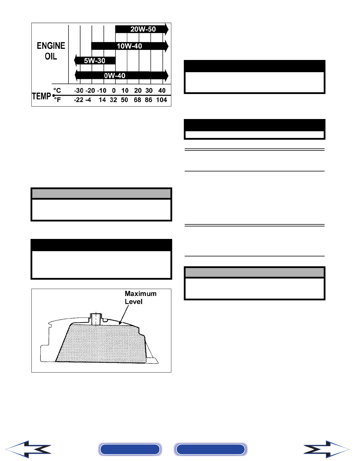
Engine Oil (recommended) SAE 10W-40
Differential/Rear Drive
Lubricant
SAE Approved
80W-90 Hypoid
Belt Width 35.0 mm (1.38 in.)
Brake Fluid DOT 4
Taillight/Brakelight 12V/8W/27W
Headlight 12V/27W (2)
Starting System Electric
Back to TOC Back to Section TOC Next
1-3
1
Break-In Procedure
A new vehicle and an overhauled engine require a
“break-in” period. The first 10 hours (or 200 miles)
are most critical to the life of this vehicle. Proper
operation during this break-in period will help
assure maximum life and performance from the
vehicle.
During the first 10 hours (or 200 miles) of operation,
always use less than 1/2 throttle. Varying the engine
RPM during the break-in period allows the compo-
nents to “load” (aiding the mating process) and then
“unload” (allowing components to cool). Although
it is essential to place some stress on the engine
components during break-in, care should be taken
not to overload the engine too often. Do not pull a
trailer or carry heavy loads during the 10-hour
break-in period.
When the engine starts, allow it to warm up prop-
erly. Idle the engine several minutes until the engine
has reached normal operating temperature. Do not
idle the engine for excessively long periods of time.
During the break-in period, a maximum of 1/2 throt-
tle is recommended; however, brief full-throttle
accelerations and variations in driving speeds con-
tribute to good engine break-in.
During the break-in period (or whenever the brake
pads are replaced), the hydraulic brake pads must be
burnished. Slow disc-speed hydraulic brakes must
be properly burnished in order to achieve maximum
stopping power.
NOTE: Do not be reluctant to heat up the brake
pads during the burnishing procedure.
After the completion of the break-in period, the
engine oil and oil filter should be changed. Other
maintenance after break-in should include checking
of all prescribed adjustments and tightening of all
fasteners.
Gasoline — Oil —
Lubricant
RECOMMENDED GASOLINE
The recommended gasoline to use is 87 minimum
octane regular unleaded. In many areas, oxygenates
(either ethanol or MTBE) are added to the gasoline.
Oxygenated gasolines containing up to 10% ethanol,
5% methane, or 5% MTBE are acceptable gasolines.
When using ethanol blended gasoline, it is not nec-
essary to add a gasoline antifreeze since ethanol will
prevent the accumulation of moisture in the fuel sys-
tem.
RECOMMENDED ENGINE/
TRANSMISSION OIL
The recommended oil to use is Arctic Cat 4-Cycle
Engine Oil (p/n 0436-005) or an equivalent oil
which is rated SE, SF, or SG under API service clas-
sification. These oils meet all of the lubrication
requirements of the Arctic Cat engine. The recom-
mended engine oil viscosity is SAE 10W-40. Ambi-
ent temperature should determine the correct weight
of oil. See the following viscosity chart for details.
! CAUTION
BRAKE PADS MUST BE BURNISHED TO ACHIEVE
FULL BRAKING EFFECTIVENESS. Braking dis-
tance will be extended until brake pads are properly
burnished.
TO PROPERLY BURNISH THE BRAKES, USE FOL-
LOWING PROCEDURE:
• Choose an area sufficiently large to safely accel-
erate vehicle to 30 mph and to brake to a stop.
• Accelerate to 30 mph; then compress brake
lever to decelerate to 0-5 mph.
• Repeat procedure five times until brakes are bur-
nished.
• This procedure burnishes the brake pads, stabi-
lizes the pad material, and extends the life of the
brake pads.
! WARNING
Do not attempt sudden stops or put the vehicle into
a situation where a sudden stop will be required
until the brake pads are properly burnished.
! CAUTION
Do not use white gas. Only Arctic Cat approved
gasoline additives should be used.
! CAUTION
Any oil used in place of the recommended oil could
cause serious engine damage. Do not use oils
which contain graphite or molybdenum additives.
These oils can adversely affect clutch operation.
Also, not recommended are racing, vegetable, non-
detergent, and castor-based oils.
Back to TOC Back to Section TOC Next
Back
1-4
OILCHARTB
RECOMMENDED FRONT
DIFFERENTIAL/REAR DRIVE
LUBRICANT
The recommended lubricant is Arctic Cat Gear Lube
(p/n 0436-007) or an equivalent gear lube which is
SAE approved 80W-90 hypoid. This lubricant meets
all of the lubrication requirements of the Arctic Cat
vehicle front differentials and rear drives.
FILLING GAS TANK
ATV0049B
Since gasoline expands as its temperature rises, the
gas tank must be filled to its rated capacity only.
Expansion room must be maintained in the tank par-
ticularly if the tank is filled with cold gasoline and
then moved to a warm area.
Tighten the gas tank cap securely after filling the
tank.
Genuine Parts
When replacement of parts is necessary, use only
genuine Arctic Cat parts. They are precision-made
to ensure high quality and correct fit. Refer to the
Illustrated Parts Manual for the correct part number,
quantity, and description.
Preparation
For Storage
Arctic Cat recommends the following procedure to
prepare the vehicle for storage.
1. Clean the seat cushion (cover and base) with a
damp cloth and allow it to dry.
2. Clean the vehicle thoroughly by washing dirt,
oil, grass, and other foreign matter from the
entire vehicle. Allow it to dry thoroughly. DO
NOT get water into any part of the engine or air
intake.
! CAUTION
Any lubricant used in place of the recommended
lubricant could cause serious front differential/rear
drive damage.
! WARNING
Always fill the gas tank in a well-ventilated area.
Never add fuel to the gas tank near any open flames
or with the engine running. DO NOT SMOKE while
filling the gas tank.
! WARNING
Do not overflow gasoline when filling the gas tank.
A fire hazard could materialize. Always allow the
engine to cool before filling the gas tank.
! WARNING
Do not over-fill the gas tank.
! CAUTION
Prior to storing the vehicle, it must be properly ser-
viced to prevent rusting and component deteriora-
tion.
Back to TOC Back to Section TOC Next
Back
1-5
1
3. Either drain the gas tank or add Fuel Stabilizer
(p/n 0638-165) to the gas in the gas tank.
Remove the air filter housing cover and air fil-
ter. Start the engine and allow it to idle; then
using Arctic Cat Engine Storage Preserver (p/n
0636-177), rapidly inject the preserver into the
air filter opening for a period of 10 to 20 sec-
onds; then stop the engine. Install the air filter
and housing cover.
4. Drain the carburetor float chamber.
5. Plug the exhaust hole in the exhaust system with
a clean cloth.
6. Apply light oil to the plungers of the shock
absorbers.
7. Tighten all nuts, bolts, cap screws, and screws.
Make sure rivets holding components together
are tight. Replace all loose rivets. Care must be
taken that all calibrated nuts, cap screws, and
bolts are tightened to specifications.
8. Fill the cooling system to the bottom of the
stand pipe in the radiator neck with properly
mixed coolant.
9. Disconnect the battery cables; then remove the
battery, clean the battery posts and cables, and
store in a clean, dry area.
10. Store the vehicle indoors in a level position.
Preparation After
Storage
Taking the vehicle out of storage and correctly pre-
paring it will assure many miles and hours of trou-
ble-free riding. Arctic Cat recommends the
following procedure to prepare the vehicle.
1. Clean the vehicle thoroughly.
2. Clean the engine. Remove the cloth from the
exhaust system.
3. Check all control wires and cables for signs of
wear or fraying. Replace if necessary.
4. Change the engine/transmission oil and filter.
5. Check the coolant level and add properly mixed
coolant as necessary.
6. Charge the battery; then install. Connect the bat-
tery cables.
7. Check the entire brake systems (fluid level,
pads, etc.), all controls, headlights, taillight,
brakelight, and headlight aim; adjust or replace
as necessary.
8. Tighten all nuts, bolts, cap screws, and screws
making sure all calibrated nuts, cap screws, and
bolts are tightened to specifications.
9. Check tire pressure. Inflate to recommended
pressure as necessary.
10. Make sure the steering moves freely and does
not bind.
11. Check the spark plug. Clean or replace as neces-
sary.
12. Follow the recommendations found in the pre-
start inspection.
! CAUTION
If the interior of the air filter housing is dirty, clean
the area before starting the engine.
! CAUTION
Avoid storing outside in direct sunlight and avoid
using a plastic cover as moisture will collect on the
vehicle causing rusting.
! CAUTION
The ignition switch must be in the OFF position
prior to installing the battery or damage may occur
to the ignition system.
! CAUTION
Connect the positive battery cable first; then the
negative.
Back to TOC Back to Section TOC
Back

2-1
2
SECTION 2 —
PERIODIC MAINTENANCE/TUNE-UP
TABLE OF
CONTENTS
Periodic Maintenance Chart…………………….……….. 2-2
Lubrication Points…..…………….…………….…………... 2-3
Battery…………….………….…………….…………….…….. 2-3
Fuses …………..………………………..…………….……….. 2-4
Air Cleaner/Filter ………………………..…………….…….. 2-4
Valve/Tappet Clearance
(Feeler Gauge Procedure) ………..………….……….. 2-6
Valve/Tappet Clearance
(Valve Adjuster Procedure) …………………..……….. 2-6
Testing Engine Compression……..…………….……….. 2-7
Spark Plug…….…………….………….…………….……….. 2-8
Muffler/Spark Arrester ……..…………….…………….….. 2-8
Gas/Vent Hoses ……….……………..…………….……….. 2-9
Adjusting Throttle Cable …………………………………... 2-9
Adjusting Engine RPM (Idle) .………….…………….….. 2-9
Engine/Transmission Oil — Filter….…………….……… 2-10
Front Differential/Rear Drive Lubricant ……………… 2-11
Tires ………………….…………….………….…………….… 2-12
Steering Components ……………………………….…… 2-12
Driveshaft/Coupling …………………….…………….…… 2-12
Suspension/Shock Absorbers/Bushings …………… 2-12
Nuts/Bolts/Cap Screws……………..…………….……… 2-13
Ignition Timing.…………….…………….………….……… 2-13
Headlight/Taillight-Brakelight ……………..……………. 2-13
Switches ………………………..………….…………….…… 2-14
Low Range/High Range/Neutral/Reverse Lever…. 2-14
Frame/Welds ………………….………….…………….…… 2-15
Electrical Connections…..…………….…………….…… 2-15
Hydraulic Brake System ………………………….……… 2-15
Parking Brake…..…………….…………….…………….… 2-17
Burnishing Brake Pads……….…………….……………. 2-19
Coolant ……………………….…………….…………….…… 2-19
Checking/Replacing V-Belt…….…………….…………. 2-19

2-2
Periodic Maintenance
Chart
A = Adjust I = Inspect
C = Clean L = Lubricate
D = Drain R = Replace
* Service/Inspect more frequently when operating in adverse conditions.
Item
Initial
Service
After
Break-In
(First Mo or
100 Mi)
Every
Day
Every
Month or
Every 100
Miles
Every 3
Months or
Every 300
Miles
Every 6
Months or
Every 500
Miles
Every Year
or Every
1500 Miles
As
Needed
Battery I I C
Fuses IR
Air Filter/Drain Tube I I C* R
Valve/Tappet Clearance I I A
Engine Compression I
Spark Plug I I R (4000 Mi
or 18 Mo)
Muffler/Spark Arrester C R
Gas/Vent Hoses I I R (2 Yrs)
Throttle Cable I I C-L A-R
Carb Float Chamber D*
Engine RPM (Idle) I I A
Engine-Transmission Oil
Level
I A
Engine-Transmission
Oil/Filter
RR* R
Oil Strainer I I C
Front Differential/Rear Drive
Lubricant
IR (4 Yrs)
Tires/Air Pressure I I R
Steering Components I I I R
V-Belt (Automatic) I l R
Suspension (Ball joint
boots, drive axle boots front
and rear, tie rods, differen-
tial and rear drive bellows)
II R
Nuts/Cap Screws/Screws I I I A
Ignition Timing I
Headlight/Taillight-
Brakelight
II R
Switches I I R
Shift Lever IA—L
Gauges/Indicators I I R
Frame/Welds I I l
Electrical Connections lC
Complete Brake System
(Hydraulic & Parking)
II C L—R
Brake Pads I I* R
Brake Fluid I I R (2 Yrs)
Brake Hoses I I R (4 Yrs)
Coolant/Cooling System I I R (2 Yrs)
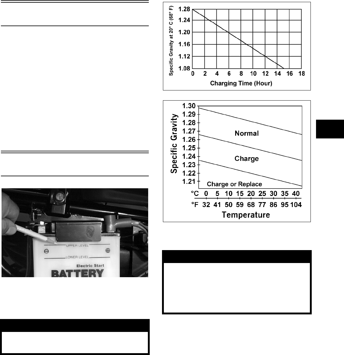
2-3
2
Lubrication Points
It is advisable to lubricate certain components peri-
odically to ensure free movement. Apply light oil to
the components using the following list as reference.
A. Accelerator Pedal Pivot/Cable Ends
B. Brake Pedal Pivot
C. Parking Brake Cable Ends
D. Shift Linkage
E. Differential Lock Cable End
F. Idle RPM Screw (Carburetor)
Battery
AF879D
The level of the battery fluid must be kept between
the upper and lower level lines at all times. If the
level drops below the lower level line, add only dis-
tilled water until it reaches upper level line.
If the battery is discharged, remove the battery from
the vehicle and charge the battery at the standard
charging rate of 1.5A x 10 hr.
CHARGTIM
CHARGE
To remove and charge the battery, use the following
procedure.
1. Remove the fasteners holding the left-rear
splash panel in place; then remove the battery
access panel.
! WARNING
Battery acid is harmful if it contacts eyes, skin, or
clothing. Care must be taken whenever handling a
battery.
! WARNING
Anytime service is performed on a battery, the fol-
lowing must be observed: keep sparks, open flame,
cigarettes, or any other flame away. Always wear
safety glasses. Protect skin and clothing when han-
dling a battery. When servicing battery in enclosed
space, keep the area well-ventilated. Make sure bat-
tery venting is not obstructed.
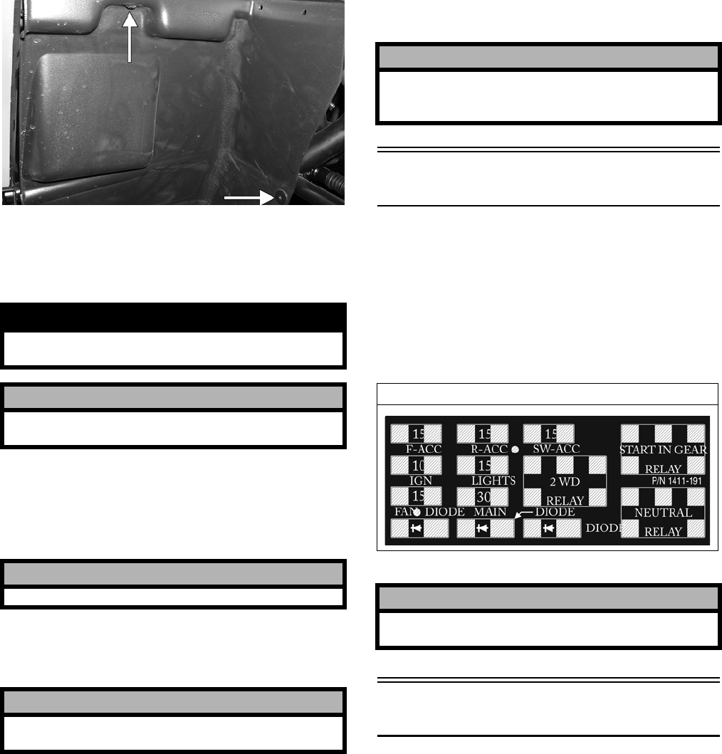
2-4
PR054A
2. Remove the negative battery cable; then remove
the positive cable and the battery vent tube.
Remove the battery from the vehicle. Care
should be taken not to damage the vent tube.
3. Remove the vent plugs; then (if necessary) fill
the battery with distilled water to the upper
level indicated on the battery.
4. Trickle charge the battery at 1.5A for 10 hours.
5. After charging, check fluid level and fill with
distilled water as necessary; then install vent
plugs.
6. Attach the vent tube and check the vent tube to
make sure it is not crimped or obstructed in any
way and that it is properly routed through and
secured to the frame.
7. Connect cables to the proper terminals: positive
cable to the positive terminal (+) and negative
cable to the negative terminal (-). Connect the
negative cable last.
8. Place the battery into position in the vehicle and
secure with the battery access panel.
Fuses
The main fuses are located in a power distribution
module under the operator’s seat.
If there is any type of electrical system failure,
always check the fuses first.
NOTE: To remove the fuse, compress the locking
tabs on either side of the fuse case and lift out.
1411-191
Air Cleaner/Filter
The air filter inside the air filter housing must be
kept clean to provide good engine power and gas
mileage. If the vehicle is used under normal condi-
tions, service the filter at the intervals specified. If
operated in dusty, wet, or muddy conditions, inspect
and service the filter more frequently. Use the fol-
lowing procedure to remove the filter and inspect
and/or clean it.
! WARNING
Avoid spillage and contact with skin, eyes, and
clothing.
! CAUTION
Do not charge the battery while it is in the vehicle
with the battery terminals connected.
! CAUTION
Never exceed the standard charging rate.
! CAUTION
Before installing the battery, make sure the ignition
switch is in the OFF position.
! CAUTION
Connecting cables in reverse (positive to negative
and negative to positive) can cause serious dam-
age to the electrical system.
Prowler XT
! CAUTION
Always replace a blown fuse with a fuse of the
same type and rating.
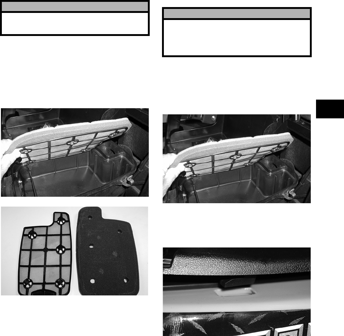
2-5
2
CLEANING AND INSPECTING
FILTER
1. Remove the seats; then remove the center con-
sole.
2. Unsnap the four fasteners securing the air
cleaner housing cover and remove the cover.
3. Remove the air filter/filter screen assembly and
separate the foam filter from the screen.
PR101
CD747
4. Fill a wash pan larger than the filter with a
non-flammable cleaning solvent; then dip the
filter in the solvent and wash it.
NOTE: Foam Filter Cleaner (p/n 0436-194) and
Foam Filter Oil (p/n 0436-195) are available from
Arctic Cat.
5. Dry the filter.
6. Put the filter in a plastic bag; then pour in air fil-
ter oil and work the filter. Reattach the filter to
the filter screen.
7. Clean any dirt or debris from inside the air
cleaner. Be sure no dirt enters the carburetors.
8. Place the filter assembly in the air filter housing
making sure it is properly positioned and prop-
erly seated with the filter screen down.
PR090
9. Install the air filter housing cover and secure
with the retaining clips; then install the center
console and seats making sure the seats lock
securely.
CD670
CHECKING AND CLEANING
DRAINS
1. Inspect one-way drains beneath the main hous-
ing for debris and for proper sealing.
! CAUTION
Failure to inspect the air filter frequently if the vehi-
cle is used in dusty, wet, or muddy conditions can
damage the engine.
! CAUTION
A torn air filter can cause damage to the vehicle
engine. Dirt and dust may get inside the engine if
the element is torn. Carefully examine the element
for tears before and after cleaning it. Replace the
element with a new one if it is torn.
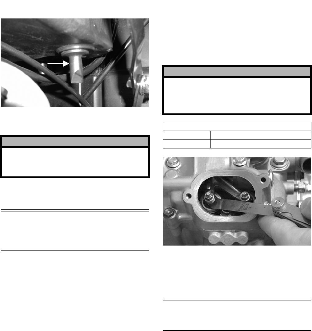
2-6
PR141A
2. Replace any one-way drain that is cracked or
shows any signs of hardening or deterioration.
3. Wipe any accumulation of oil or gas from the
filter housing and one-way drains.
Valve/Tappet
Clearance
(Feeler Gauge Procedure)
To check and adjust valve/tappet clearance, use the
following procedure.
NOTE: The engine must be cold for this proce-
dure.
NOTE: The seats, center console, and air filter
housing must be removed for this procedure.
1. Remove the timing inspection plug; then
remove the tappet covers (for more detailed
information, see Section 3 — Servicing Top-Side
Components).
2. Rotate the crankshaft to the TDC position on the
compression stroke.
NOTE: At this point, the rocker arms and
adjuster screws must not have pressure on them.
3. Using a feeler gauge, check each valve/tappet
clearance. If clearance is not within specifica-
tions, loosen the jam nut and rotate the tappet
adjuster screw until the clearance is within spec-
ifications. Tighten each jam nut securely after
completing the adjustment.
CC007D
4. Install the timing inspection plug.
5. Place the two tappet covers into position making
sure the proper cap screws are with the proper
cover. Tighten the cap screws securely.
Valve/Tappet Clearance
(Valve Adjuster Procedure)
To check and adjust valve/tappet clearance, use the
following procedure.
NOTE: The engine must be cold for this proce-
dure.
NOTE: The seats, center console, and air filter
housing must be removed for this procedure.
1. Remove the timing inspection plug; then
remove the tappet covers (for more detailed
information, see Section 3 — Servicing Top-Side
Components).
2. Rotate the crankshaft to the TDC position on the
compression stroke.
! CAUTION
The one-way drain to the left is the clean air section
of the filter housing. Any leak of this one-way drain
will allow dirt into the engine intake causing severe
engine damage.
! CAUTION
The feeler gauge must be positioned at the same
angle as the valve and valve adjuster for an accu-
rate measurement of clearance. Failure to measure
the valve clearance accurately could cause valve
component damage.
VALVE/TAPPET CLEARANCE
Intake 0.1016 mm (0.004 in.)
Exhaust 0.1524 mm (0.006 in.)
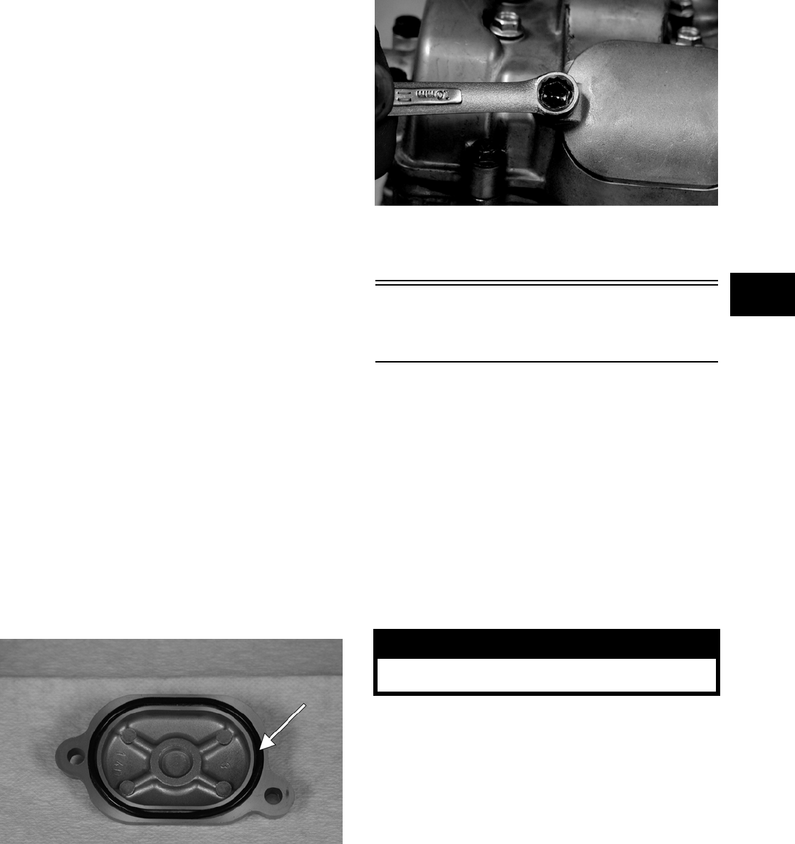
2-7
2
NOTE: At this point, the rocker arms and
adjuster screws must not have pressure on them.
NOTE: Use Valve Clearance Adjuster (p/n
0444-078) for this procedure.
3. Place the valve adjuster onto the jam nut secur-
ing the tappet adjuster screw; then rotate the
valve adjuster dial clockwise until the end is
seated in the tappet adjuster screw.
4. While holding the valve adjuster dial in place,
use the valve adjuster handle and loosen the jam
nut; then rotate the tappet adjuster screw clock-
wise until friction is felt.
5. Align the valve adjuster handle with one of the
marks on the valve adjuster dial.
6. While holding the valve adjuster handle in
place, rotate the valve adjuster dial counter-
clockwise until proper valve/tappet clearance is
attained.
NOTE: Refer to the appropriate specifications in
Feeler Gauge Procedure sub-section for the proper
valve/tappet clearance.
NOTE: Rotating the valve adjuster dial counter-
clockwise will open the valve/tappet clearance by
0.05 mm (0.002 in.) per mark.
7. While holding the adjuster dial at the proper
clearance setting, tighten the jam nut securely
with the valve adjuster handle.
8. Place the two tappet covers with O-rings into
position; then tighten the covers securely.
CF006A
CF005
9. Install the spark plug; then install the timing
inspection plug.
Testing Engine
Compression
To test engine compression, use the following pro-
cedure.
NOTE: The engine must be warm and the battery
must be fully charged for this test.
NOTE: The seats and center console must be
removed for this procedure.
1. Remove the high tension lead from the spark
plug.
2. Using compressed air, blow any debris from
around the spark plug.
3. Remove the spark plug; then attach the high ten-
sion lead to the plug and ground the plug on the
cylinder head well away from the spark plug
hole.
4. Attach the Compression Gauge (p/n 0444-096).
5. While holding the throttle in the full-open posi-
tion, crank the engine over with the electric
starter until the gauge shows a peak reading
(five to 10 compression strokes).
NOTE: The compression should be within a
range of 63-77 psi in the full-open throttle position.
! WARNING
Always wear safety glasses when using com-
pressed air.
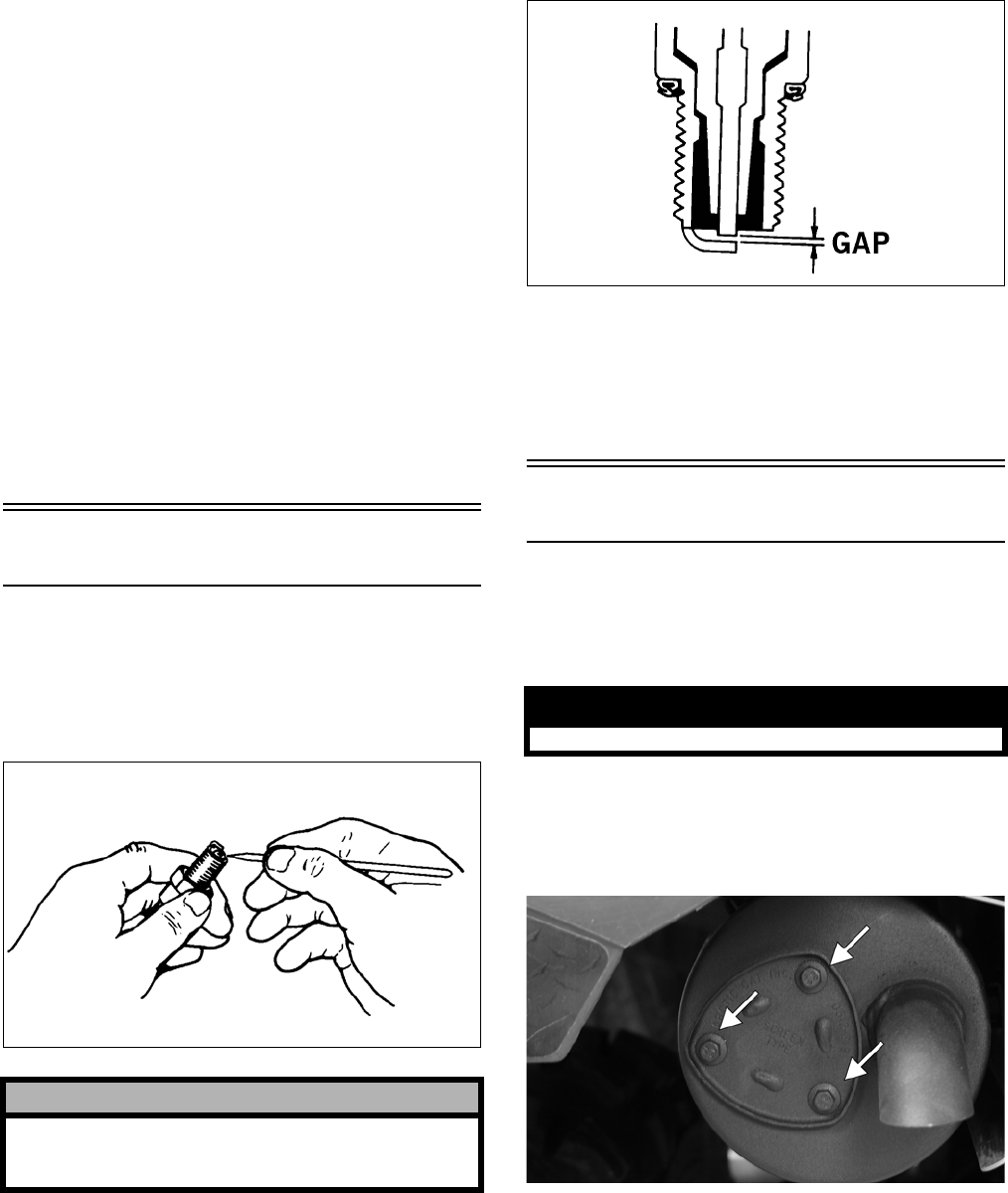
2-8
6. If compression is abnormally low, inspect the
following items.
A. Verify starter cranks engine over.
B. Gauge is functioning properly.
C. Throttle lever in the full-open position.
D. Valve/tappet clearance correct.
E. Valve bent or burned.
F. Valve seat burned.
NOTE: To service valves, see Section 3.
7. Pour 29.5 ml (1 fl oz) of oil into the spark plug
hole, reattach the gauge, and retest compression.
8. If compression is now evident, service the piston
rings (see Section 3).
Spark Plug
A light brown insulator indicates that the plug is
correct. A white or dark insulator indicates that the
engine may need to be serviced or the carburetor
may need to be adjusted. To maintain a hot, strong
spark, keep the plug free of carbon.
ATV-0051
Adjust the gap to 0.7 — 0.8 mm (0.028 — 0.032 in.).
ATV0052B
When installing the spark plug, be sure to tighten it
securely. A new spark plug should be tightened 1/2
turn once the washer contacts the cylinder head. A
used spark plug should be tightened 1/8 — 1/4 turn
once the washer contacts the cylinder head.
Muffler/Spark Arrester
The muffler has a spark arrester which must be peri-
odically cleaned. At the intervals shown in the Peri-
odic Maintenance Chart, clean the spark arrester
using the following procedure.
1. Remove the three cap screws securing the spark
arrester screen assembly to the muffler; then
loosen and remove the spark arrester. Account
for a gasket.
CF105A
! CAUTION
Before removing the spark plug, be sure to clean
the area around the spark plug. Dirt could enter
engine when removing or installing the spark plug.
! WARNING
Wait until the muffler cools to avoid burns.
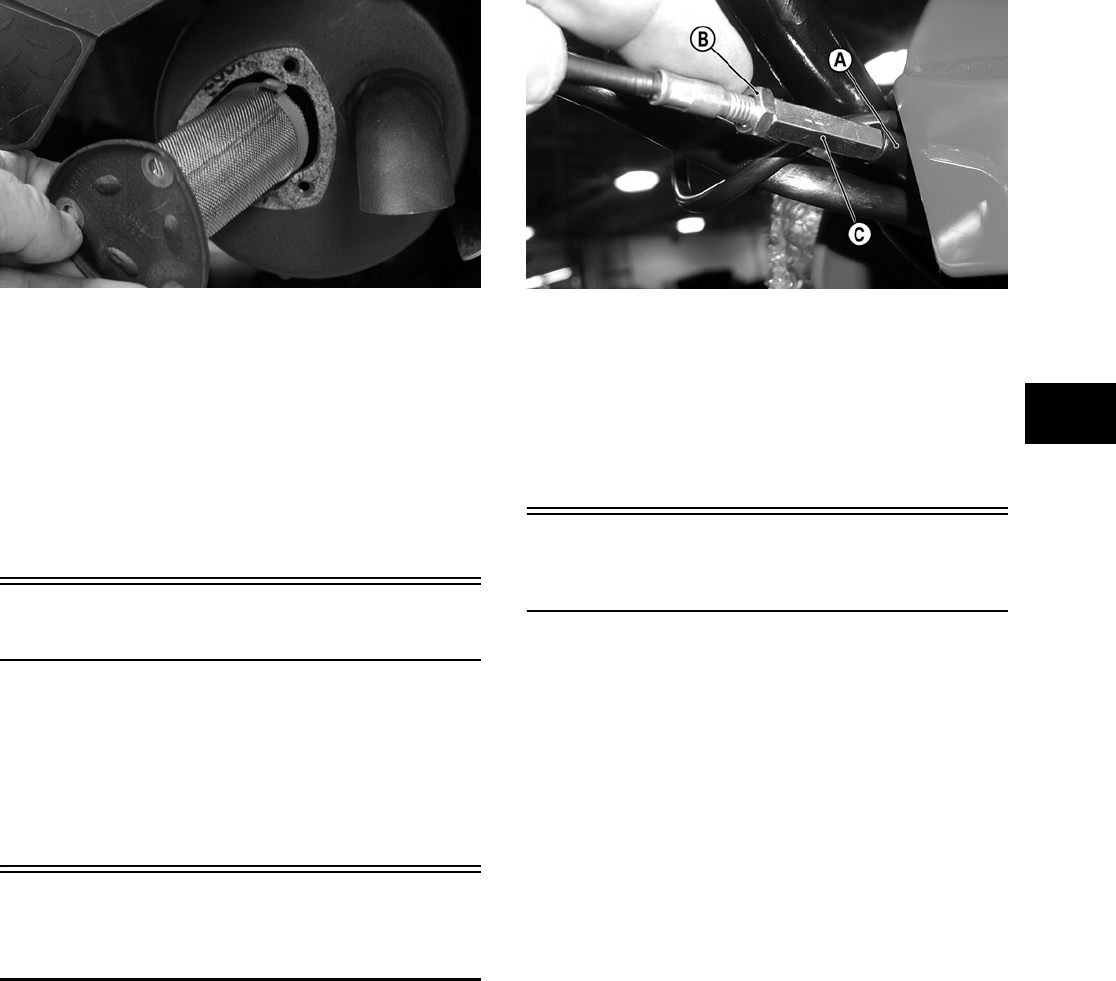
2-9
2
CF104
2. Using a suitable brush, clean the carbon deposits
from the screen taking care not to damage the
screen.
NOTE: If the screen or gasket is damaged in any
way, it must be replaced.
3. Install the spark arrester assembly and gasket
and secure with the three cap screws. Tighten
the cap screws to 0.6 kg-m (4.0 ft-lb).
Gas/Vent Hoses
Replace the gas hose every two years. Damage from
aging may not always be visible. Do not bend or
obstruct the routing of the carburetor vent hose.
Make certain that the vent hose is securely con-
nected to the carburetor and the opposite end is
always open.
Adjusting Throttle
Cable
To adjust the throttle cable free-play, locate the
in-line cable adjuster behind the carburetor.
1. Slide the rubber boot (A) away; then loosen the
jam nut (B) from the throttle cable adjuster (C).
CD560A
2. Turn the adjuster until the throttle cable has
proper free-play of 3-6 mm (1/8 — 1/4 in.) at the
pedal.
3. Tighten the jam nut against the throttle cable
adjuster securely; then slide the rubber boot over
the adjuster.
Adjusting Engine RPM
(Idle)
To properly adjust the idle RPM, a tachometer is
necessary. To adjust idle RPM, use the following
procedure.
NOTE: To access the idle adjustment screw, it
will be necessary to remove the seats and center
console.
1. Set the parking brake. With the transmission in
neutral, start the engine and warm it up to nor-
mal operating temperature.
2. Turn the idle adjustment screw clockwise one
turn past the recommended RPM setting; then
turn it counterclockwise to 1250-1350 RPM.
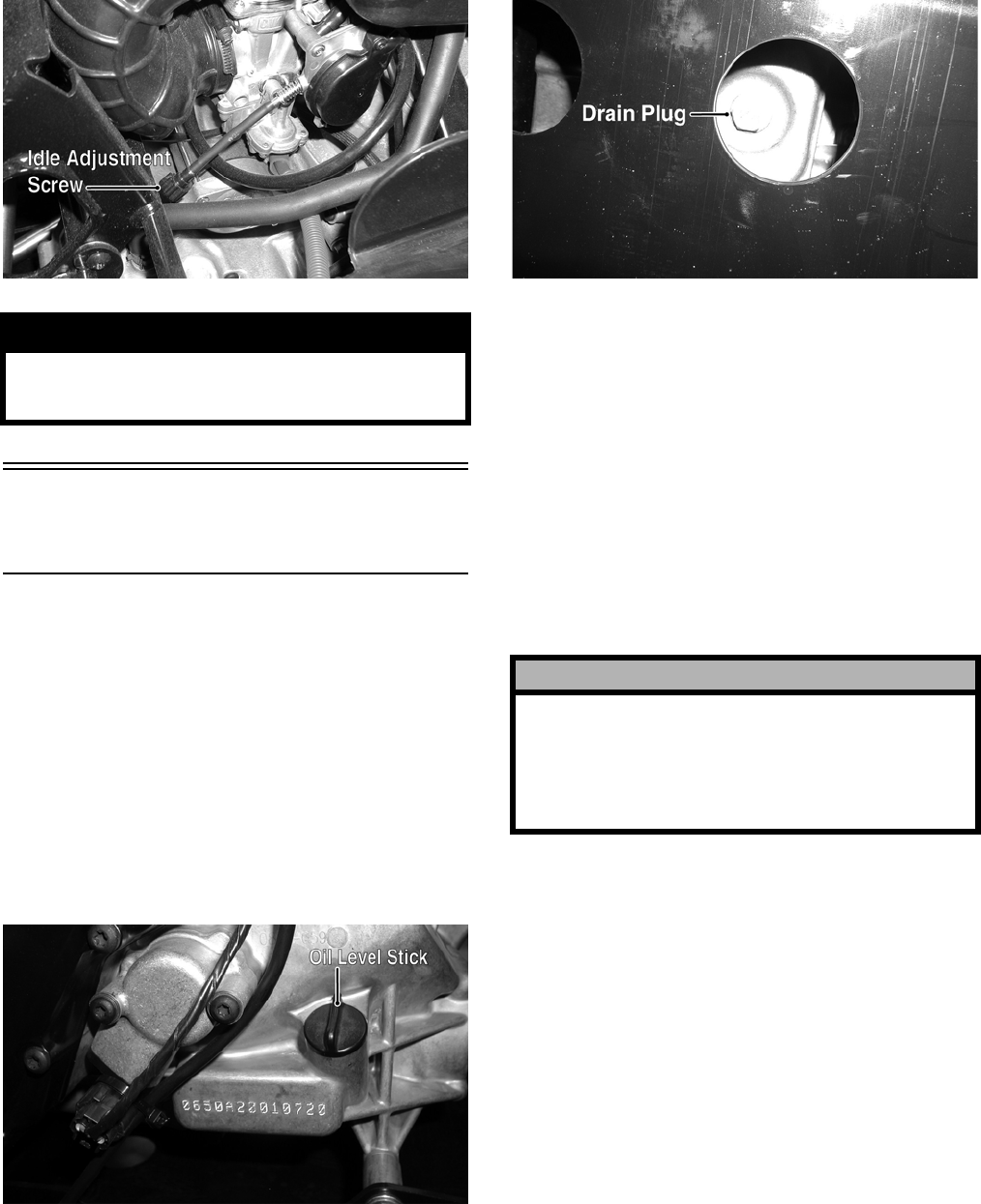
2-10
PR081A
Engine/Transmission
Oil — Filter
OIL — FILTER
Change the engine oil and oil filter at the scheduled
intervals. The engine should always be warm when
the oil is changed so the oil will drain easily and
completely.
NOTE: To change oil and filter, the seats and
center console must be removed.
1. Park the vehicle on level ground.
2. Remove the oil level stick/filler plug.
PR053B
3. Remove the drain plug from the bottom of the
engine and drain the oil into a drain pan.
PR078A
4. Using the Oil Filter Wrench (p/n 0444-042) and
a ratchet handle (or a socket or box-end
wrench), remove the old oil filter.
NOTE: Clean up any excess oil after removing
the filter.
5. Apply oil to a new filter O-ring and check to
make sure it is positioned correctly; then install
the new oil filter. Tighten securely.
6. Install the engine drain plug and tighten to spec-
ifications. Pour the specified amount of the rec-
ommended oil in the filler hole. Install the oil
level stick/filler plug.
7. Start the engine (while the vehicle is outside on
level ground) and allow it to idle for a few min-
utes.
8. Turn the engine off and wait approximately one
minute.
9. Unscrew the oil level stick and wipe it with a
clean cloth.
10. Install the oil level stick until the threads touch
engine case.
NOTE: The oil level stick should not be threaded
into the case for checking the oil level.
! WARNING
Adjust the idle to the correct RPM. Make sure the
engine is at normal operating temperature before
adjusting the idle RPM.
! CAUTION
Any oil used in place of the recommended oil could
cause serious engine damage. Do not use oils
which contain graphite or molybdenum additives.
These oils can adversely affect clutch operation.
Also, not recommended are racing, vegetable,
non-detergent, and castor-based oils.
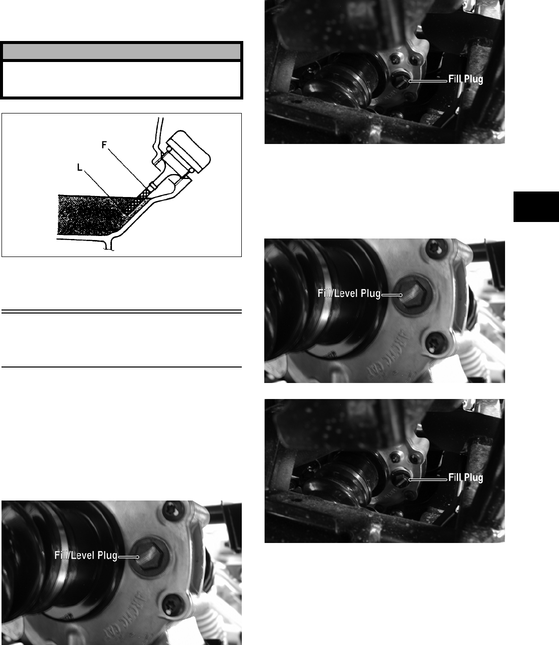
2-11
2
11. Remove the oil level stick; the engine oil level
should be above the illustrated “L” mark but not
higher than the illustrated “F” mark.
ATV-0100
12. Inspect the area around the drain plug and oil fil-
ter for leaks.
Front Differential/Rear
Drive Lubricant
Check and change the lubricant according to the
Periodic Maintenance Chart. When changing the
lubricant, use approved SAE 80W-90 hypoid gear
lube. To check lubricant, use the following proce-
dure.
1. Remove the rear drive filler plug; the lubricant
level should be 1 in. below the threads of the
plug.
PR046A
2. If low, add SAE approved 80W-90 hypoid gear
lube as necessary.
PR065A
To change the lubricant, use the following proce-
dure.
1. Place the vehicle on level ground.
2. Remove each oil filler plug.
PR046A
PR065A
3. Drain the oil into a drain pan by removing in
turn the drain plug from each.
! CAUTION
Do not over-fill the engine with oil. Always make
sure that the oil level is above the “L” m a r k b u t n o t
higher than the “F” mark.
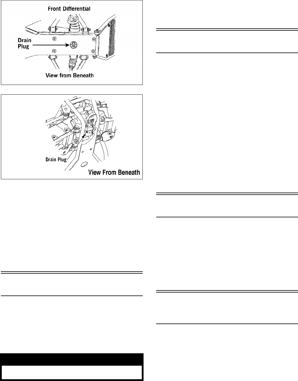
2-12
ATV0082A
737-651A
4. After all the oil has been drained, install the
drain plugs and tighten to specifications.
5. Pour the appropriate amount of recommended
oil into the filler hole.
6. Install the filler plugs.
NOTE: If the differential/rear drive oil is contami-
nated with water, inspect the drain plug, filler plug,
and/or bladder.
Tires
TIRE SIZES
The Prowler XT is equipped with low-pressure
tubeless tires of the size and type listed (see Section
1). Do not under any circumstances substitute tires
of a different type or size.
TIRE INFLATION PRESSURE
Front and rear tire inflation pressure should be 0.70
kg-cm² (10 psi).
A low-pressure gauge is provided in the tool kit to
measure the air pressure in the tires. Check the air
pressure in all tires before each use of the vehicle.
Steering Components
The following steering components should be
inspected periodically to ensure safe and proper
operation.
A. Steering wheel secure.
B. Steering has equal and complete full-left and
full-right capability.
C. Steering sector mounting bolts tight.
D. Ball joints not worn, cracked, or damaged.
E. Tie rods not bent or cracked.
F. Knuckles not worn, cracked, or damaged.
G. Cotter pins not damaged or missing.
Driveshaft/Coupling
The following drive system components should be
inspected periodically to ensure proper operation.
A. Spline lateral movement (slop).
B. Coupling cracked, damaged, or worn.
C. Universal joints worn or missing bearings.
Suspension/Shock
Absorbers/Bushings
The following suspension system components
should be inspected periodically to ensure proper
operation.
A. Shock absorber rods bent, pitted, or damaged.
B. Rubber damper cracked, broken, or missing.
C. Shock absorber body damaged, punctured, or
leaking.
D. Shock absorber eyelets broken, bent, or
cracked.
! WARNING
Always use the size and type of tires specified.
Always maintain proper tire inflation pressure.
Rear Drive

2-13
2
E. Shock absorber eyelet bushings worn, deteri-
orated, cracked, or missing.
F. Shock absorber spring broken or sagging.
G. Sway bar mountings tight and bushings
secure.
Nuts/Bolts/Cap Screws
Tighten all nuts, bolts, and cap screws. Make sure
rivets holding components together are tight.
Replace all loose rivets. Care must be taken that all
calibrated nuts, bolts, and cap screws are tightened
to specifications. For proper torque values, see Sec-
tion 10.
Ignition Timing
The ignition timing cannot be adjusted; however,
verifying ignition timing can aid in troubleshooting
other components. To verify ignition timing, use the
following procedure.
NOTE: To check ignition timing, the seats and
center console must be removed.
1. Attach the Timing Light (p/n 0644-197) to the
spark plug high tension lead; then remove the
timing inspection plug from the left-side crank-
case cover.
2. Start the engine and using the RPM function on
the speedometer/tachometer, run at the recom-
mended RPM; ignition timing should be the rec-
ommended degrees BTDC.
3. Install the timing inspection plug.
If ignition timing cannot be verified, the rotor may
be damaged, the key may be sheared, the trigger coil
bracket may be bent or damaged, or the CDI unit
may be faulty.
Headlight/Taillight-
Brakelight
Each time the vehicle is used, lights should be
checked for proper function. With the ignition
switch in the ON position, select the high and/or low
beam on the light switch; the headlights and taillight
should illuminate. Test the brakelight by depressing
the brake pedal. The brakelight should illuminate.
HEADLIGHT
NOTE: The bulb portion of the headlight is frag-
ile. HANDLE WITH CARE. When replacing the
headlight bulb, do not touch the glass portion of
the bulb. If the glass is touched, it must be cleaned
with a dry cloth before installing. Skin oil residue
on the bulb will shorten the life of the bulb.
To replace the headlight bulb, use the following pro-
cedure.
1. Remove the wiring harness connector from the
back of the headlight.
2. Grasp the bulb socket, turn it counterclockwise
and remove, and pull the bulb straight out of the
socket.
3. Install the new bulb into the socket and rotate it
completely clockwise in the housing.
4. Install the wiring harness connector.
TAILLIGHT-BRAKELIGHT
To replace the taillight-brakelight bulb, use the fol-
lowing procedure.
1. Remove the two machine screws and remove
the light assembly.
2. Rotate the bulb socket counterclockwise to
remove it from the light assembly; then pull
straight out on the bulb. Push the new bulb
straight into the socket.
3. Install the bulb and socket into the light assem-
bly and turn clockwise to lock in place.
4. Install the taillight-brakelight assembly on the
canopy support.
IGNITION TIMING
Prowler XT 10° BTDC @ 1500 RPM
! WARNING
Do not attempt to remove the bulb when it is hot.
Severe burns may result.
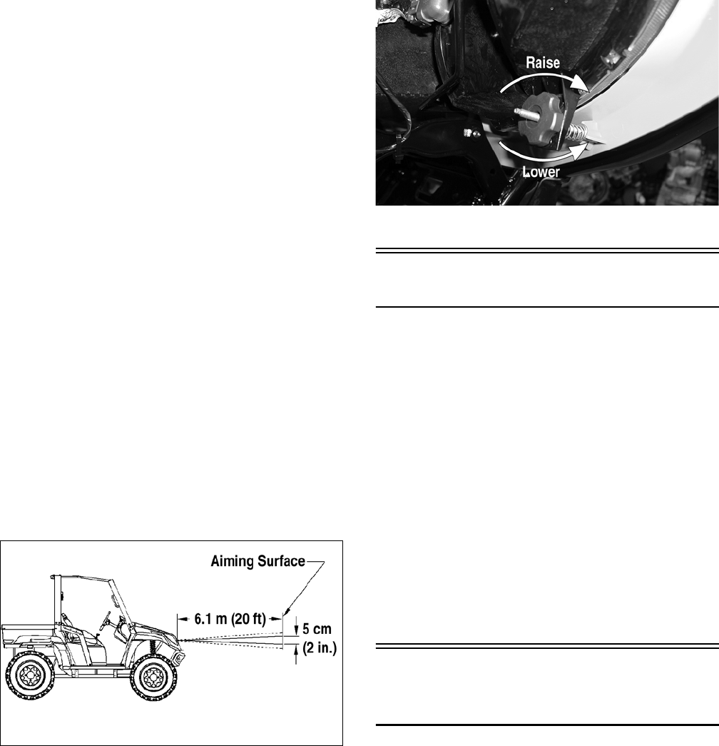
2-14
CHECKING/ADJUSTING
HEADLIGHT AIM
The headlights can be adjusted vertically. The geo-
metric center of the HIGH beam light zone is to be
used for vertical aiming.
1. Position the vehicle on a level floor so the head-
lights are approximately 6.1 m (20 ft) from an
aiming surface (wall or similar aiming surface).
NOTE: There should be an average operating
load on the vehicle when adjusting the headlight
aim.
2. Measure the distance from the floor to the
mid-point of each headlight.
3. Using the measurements obtained in step 2,
make horizontal marks on the aiming surface.
4. Make vertical marks which intersect the hori-
zontal marks on the aiming surface directly in
front of the headlights.
5. Switch on the lights. Make sure the HIGH beam
is on. DO NOT USE LOW BEAM.
6. Observe each headlight beam aim. Proper aim is
when the most intense beam is centered on the
vertical mark 5 cm (2 in.) below the horizontal
mark on the aiming surface.
0740-647
7. Using the adjuster knob, adjust each headlight
until correct aim is obtained.
CD714A
Switches
Each time the vehicle is used, switches should be
checked for proper operation. Use the following list
for reference.
A. Ignition/start switch — engine will run;
starter will engage.
B. 2WD/4WD selector switch — differential
will engage (4WD)/disengage (2WD).
C. Reverse/neutral/high/low switch — R/N/H/L
will be indicated on the LCD.
D. Headlight switch — high beam, low beam,
and lights off can be selected.
E. Brake switch — brakelight illuminates and
starter can be engaged with vehicle in gear.
Low Range/High Range/
Neutral/Reverse Lever
CHECKING SHIFT LEVER LINKAGE
Set the parking brake and turn the ignition switch
on; then with the shift lever in the neutral position,
look for the (N) indication on the LCD. Shift into
high range and look for the (H) indication, low
range for the (L) indication, and reverse for the (R)
indication. Shift the transmission into neutral and
turn the ignition switch off.
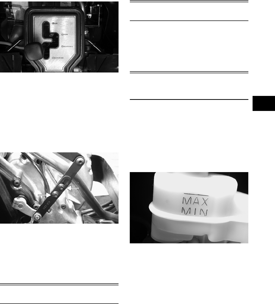
2-15
2
PR094
ADJUSTING SHIFT LEVER LINKAGE
To adjust the shift lever linkage, use the following
procedure.
1. Set the parking brake; then remove the seats and
center console.
2. Make sure the shift lever is in neutral; then
loosen the two torx-head screws and nuts on the
linkage.
PR093A
3. Holding the shift lever centered in the neutral
position, move the shifter arm until (N) is indi-
cated on the LCD.
4. Tighten the torx-head screws securely; then
recheck the adjustment by selecting each gear
position and checking for the correct indication
on the LCD.
Frame/Welds
The frame and welds should be checked periodically
for damage, bends, cracks, deterioration, broken
components, and missing components. If replace-
ment or repair constitutes removal, see Section 8.
Electrical Connections
The electrical connections should be checked peri-
odically for proper function. In case of an electrical
failure, check fuses, connections (for tightness, cor-
rosion, damage), and/or bulbs. If an electrical com-
ponent needs to be tested for proper function, see
Section 5.
Hydraulic
Brake System
CHECKING/BLEEDING
The hydraulic brake system has been filled and bled
at the factory. To check and/or bleed a hydraulic
brake system, use the following procedure.
1. With the master cylinder in a level position,
check the fluid level in the reservoir. If the level
in the reservoir is not above the MIN, add DOT
4 brake fluid.
PR095
2. Depress the brake pedal several times to check
for a firm brake. If the brake is not firm, the sys-
tem must be bled.
3. To bleed the brake system, use the following
procedure.
A. Remove the cover and fill the reservoir with
DOT 4 Brake Fluid (p/n 1639-799).
B. Install and secure the cover; then slowly
depress the brake pedal several times.
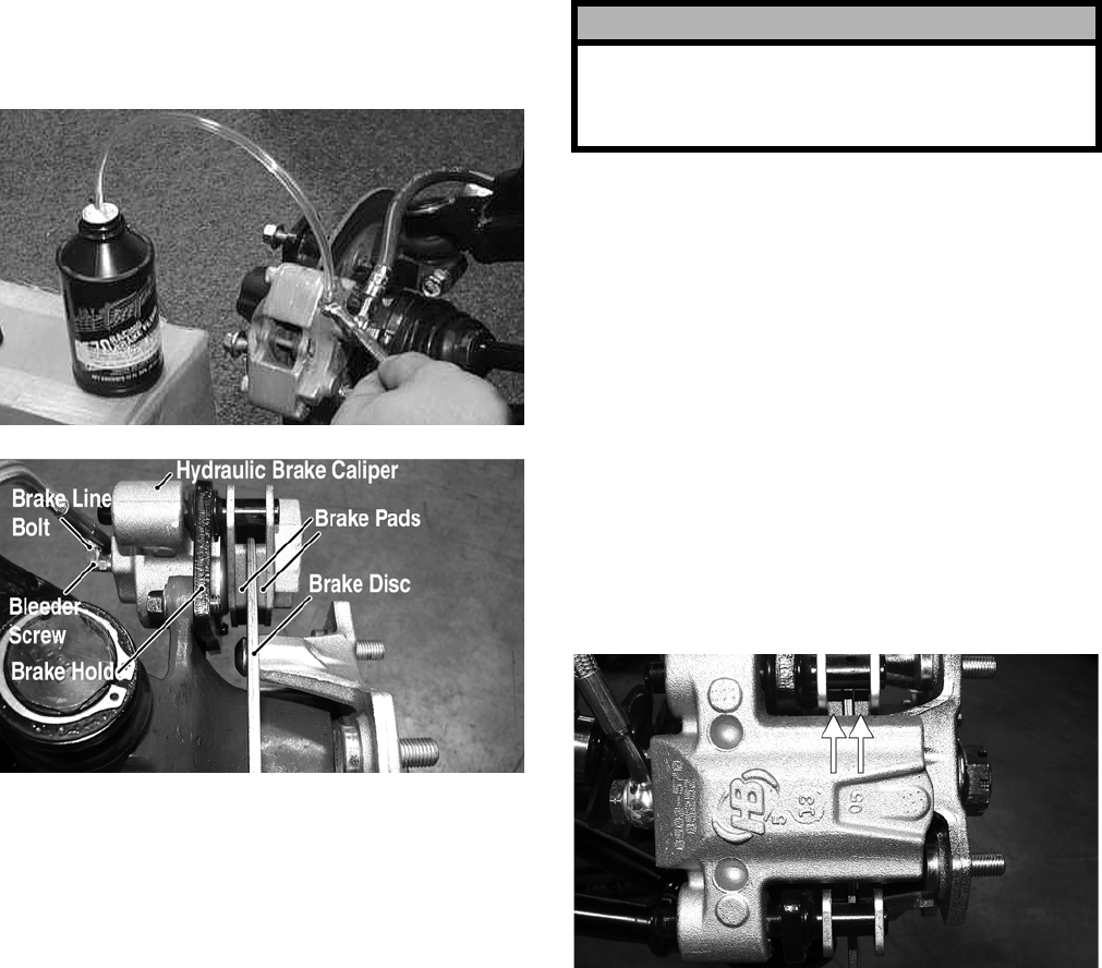
2-16
C. Remove the protective cap, install one end of
a clear hose onto one FRONT bleeder screw,
and direct the other end into a container; then
while holding slight pressure on the brake
pedal, open the bleeder screw and watch for
air bubbles. Close the bleeder screw before
releasing the brake pedal. Repeat this proce-
dure until no air bubbles are present.
AF637D
PR377A
NOTE: During the bleeding procedure, watch the
reservoir very closely to make sure there is always
a sufficient amount of brake fluid. When the level
falls below MIN, refill the reservoir before the
bleeding procedure is continued. Failure to main-
tain a sufficient amount of fluid in the reservoir will
result in air in the system.
D. At this point, perform steps B and C on the
other FRONT bleeder screw; then move to
the REAR bleeder screw and follow the same
procedure.
E. Repeat steps B and C until the brake pedal is
firm.
4. Carefully check the entire hydraulic brake sys-
tem that all hose connections are tight, the bleed
screws are tight, the protective caps are
installed, and no leakage is present.
INSPECTING HOSES
Carefully inspect the hydraulic brake hoses for
cracks or other damage. If found, the brake hoses
must be replaced.
CHECKING/REPLACING PADS
The clearance between the brake pads and brake
discs is adjusted automatically as the brake pads
wear. The only maintenance that is required is
replacement of the brake pads when they show
excessive wear. Check the thickness of each of the
brake pads as follows.
1. Remove a front wheel.
2. Measure the thickness of each brake pad.
PR376A
3. If thickness of either brake pad is less than 3.2
mm (0.125 in.), the brake pads must be replaced.
NOTE: The brake pads should be replaced as a
set.
4. To replace the brake pads, use the following pro-
cedure.
A. Remove the wheel.
B. Remove the cap screws securing the caliper
holder to the knuckle; then remove the pads
from the caliper.
! CAUTION
This hydraulic brake system is designed to use
DOT 4 brake fluid only. If brake fluid must be added,
care must be taken as brake fluid is very corrosive
to painted surfaces.
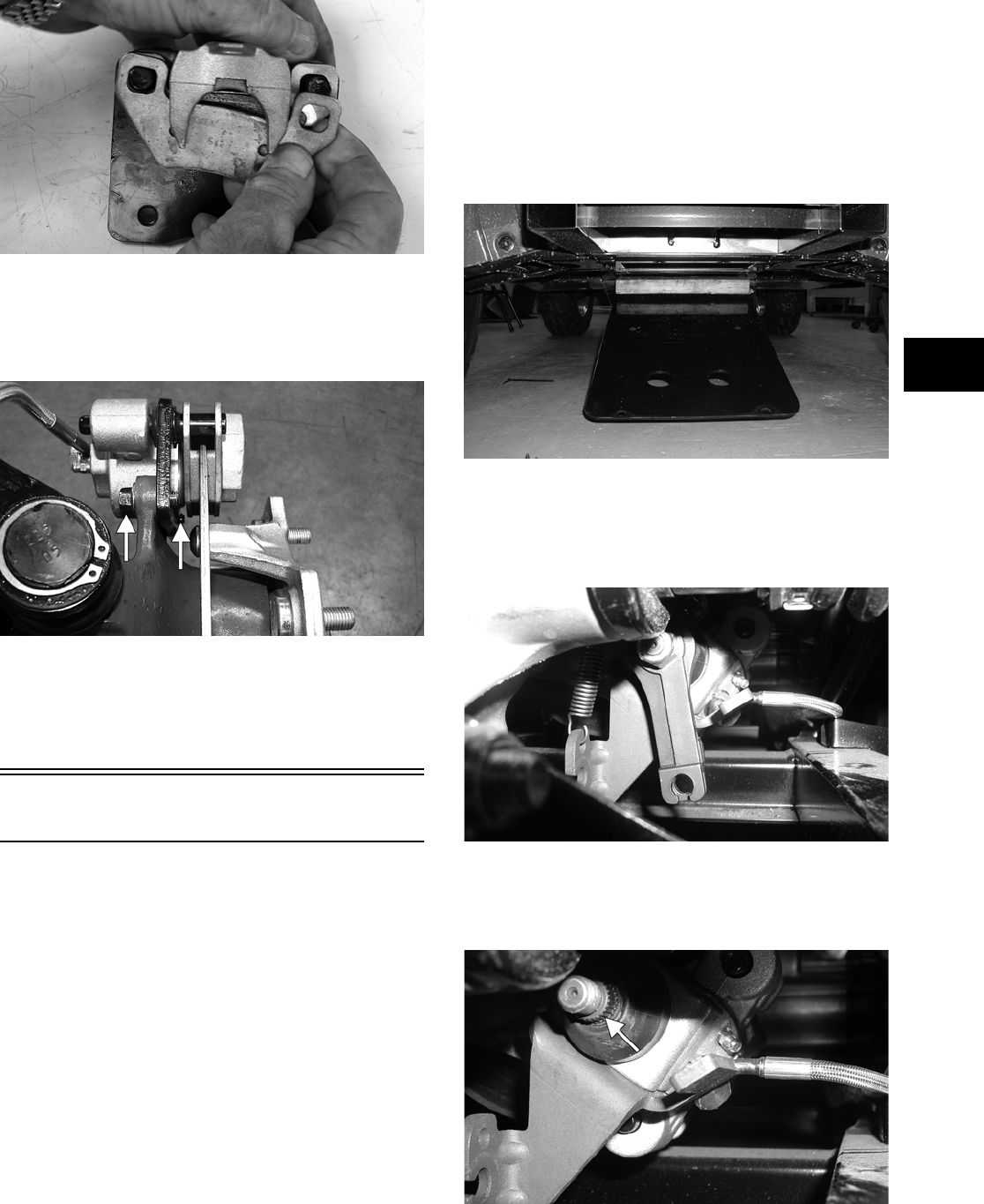
2-17
2
PR237
C. Install the new brake pads.
D. Secure the caliper holder to the knuckle with
the cap screws. Tighten to specifications.
PR377B
E. Install the wheel. Tighten to specifications.
5. Burnish the brake pads (see Burnishing Brake
Pads in this section).
Parking Brake
CHECKING
Although the parking brake has been adjusted at the
factory, the brake should be checked for proper
operation. The brake must be maintained to be fully
functional.
1. With the engine off, transmission in neutral, and
the parking brake set, attempt to move the vehi-
cle.
2. If the rear wheels are locked, it is adjusted prop-
erly.
3. If the rear wheels are not locked, it must be
adjusted (set up).
ADJUSTING
To adjust (set up) the parking brake, use the follow-
ing procedure.
NOTE: Remove the four rear body screws secur-
ing the belly panel to the frame and allow it to drop
down for better access to the parking brake actua-
tor.
PR096
1. Remove the parking brake cable from the actua-
tor lever; then remove the actuator nut and actu-
ator lever. Note the position of the lever before
removing.
PR098
2. Rotate the actuator clockwise (hand tight) until
it contacts the back of the piston; then rotate
counterclockwise approximately one spline.
PR089A
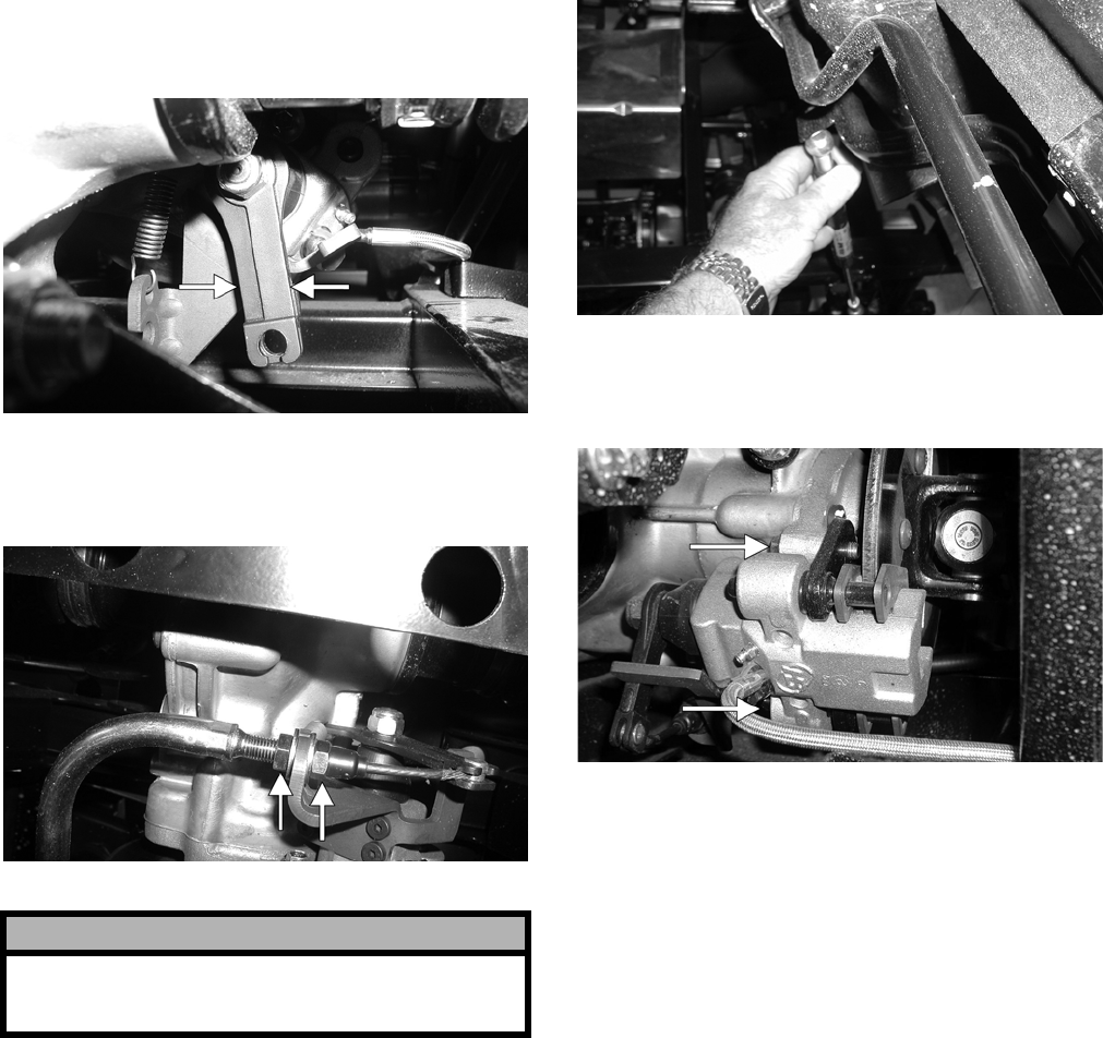
2-18
3. Install the actuator lever in the position noted in
step 1; then install the actuator nut and tighten to
4.8 kg-m (35 ft-lb).
PR098A
4. Install the parking brake cable and adjust nuts so
the parking brake holds the vehicle when set and
fully releases it when released.
PR097A
MEASURING/REPLACING BRAKE
PADS
Removing
1. Remove the parking brake cable (see Adjusting
in this sub-section).
2. Lift the cargo box; then disconnect the lift sup-
port and allow the cargo box to tilt all the way
back.
PR099
3. Remove the two cap screws securing the brake
caliper to the rear drive housing and remove the
caliper.
PR080B
4. Push in on the caliper holder and remove the
outer brake pad; then remove the inner pad.
Inspecting and Measuring
1. Inspect the pads for gouges, chips, or wear.
2. Inspect the disc for gouges, grooves, cracks, and
warpage.
3. Using a calipers, measure the thickness of each
brake pad.
4. If the thickness of either brake pad is less than
3.2 mm (0.125 in.), the brake pads must be
replaced.
NOTE: The brake pads should be replaced as a
set.
Installing
1. Place the brake pads into the caliper.
NOTE: The metal backing of the pad will be fac-
ing the actuator when installed properly.
2. Slide brake caliper assembly over the brake disc
and into position on the knuckle; then secure the
caliper with the cap screws tightened to specifi-
cations.
! CAUTION
If after adjusting the parking brake cable the park-
ing brake will not hold the vehicle, the brake pads
must be replaced.
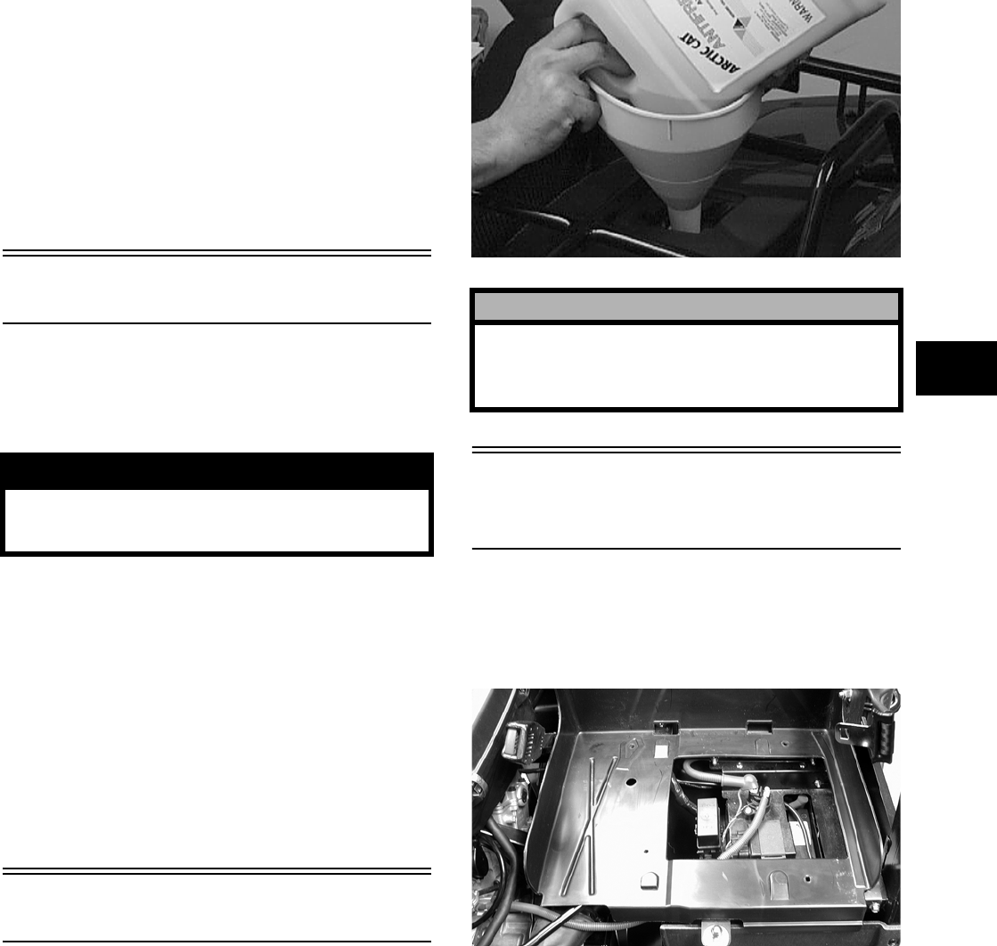
2-19
2
3. Connect the parking brake cable (see Adjusting
in this sub-section).
4. Adjust the parking brake (see Adjusting in this
sub-section).
5. Connect the lift support to the cargo box.
NOTE: Whenever installing new pads, the new
pads must be burnished (see Burnishing Brake
Pads in this section).
Burnishing Brake Pads
Brake pads must be burnished to achieve full brak-
ing effectiveness. Braking distance will be extended
until brake pads are properly burnished. To properly
burnish the brake pads, use the following procedure.
1. Choose an area large enough to safely accelerate
the vehicle to 30 mph and to brake to a stop.
2. Accelerate to 30 mph; then depress the brake
pedal to decelerate to 0-5 mph.
3. Repeat procedure five times until brake pads are
burnished.
4. Adjust the parking brake (if necessary).
5. Verify that the brakelight illuminates when the
brake pedal is depressed.
Coolant
The cooling system should be inspected daily for
leakage and damage. Also, the coolant level should
be checked periodically.
When filling the cooling system, use premixed Arc-
tic Cat Antifreeze (p/n 0638-395). While the cooling
system is being filled, air pockets may develop;
therefore, run the engine for five minutes after the
initial fill, shut the engine off, and then fill the cool-
ing system to the bottom of the stand pipe in the
radiator neck.
AN604D
Checking/Replacing
V-Belt
REMOVING
1. Remove the seats and center console; then
remove the left-side seat-base.
PR104
2. Remove the cap screws securing the V-belt
cover noting the location of the differ-
ent-lengthed cap screws for installing purposes;
then using a rubber mallet, gently tap on the
cover tabs to loosen the cover. Remove the
cover.
NOTE: Note the location of the main harness and
engine ground wires for installing purposes.
! WARNING
Failure to properly burnish the brake pads could
lead to premature brake pad wear or brake loss.
Brake loss can result in severe injury.
! CAUTION
After operating the vehicle for the initial 5-10 min-
utes, stop the engine, allow the engine to cool
down, and check the coolant level. Add coolant as
necessary.
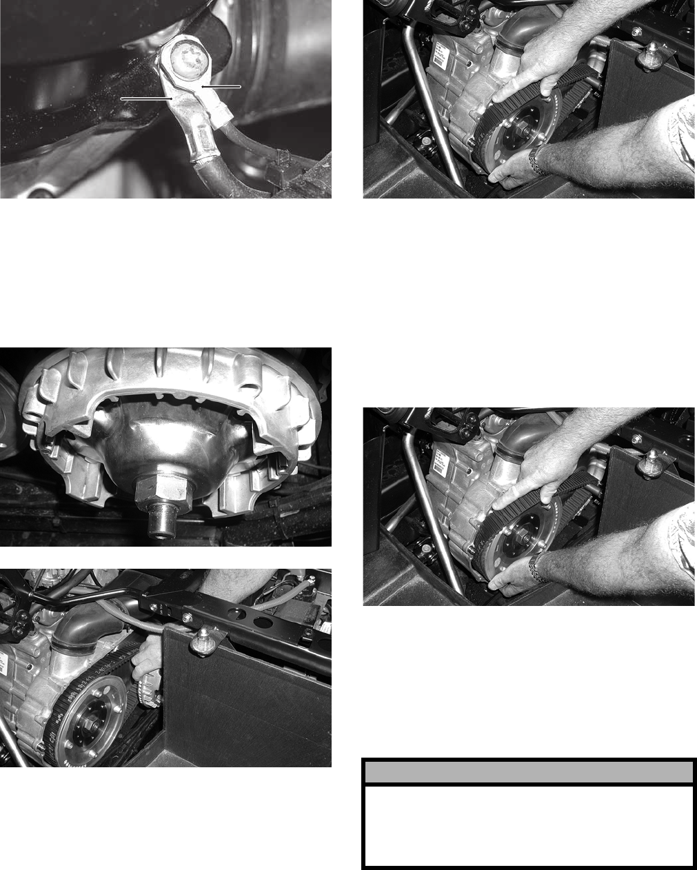
2-20
PR111A
3. Remove the nut securing the movable drive
face; then remove the face. Account for the
spacer.
NOTE: Keep the drive face plate in contact with
the drive face when removing or installing the
drive face to prevent the rollers from falling out.
PR110
PR108
4. Remove the V-belt.
PR109
INSTALLING
1. Spread the faces of the driven pulley by pushing
the inner face toward the engine while turning it
counterclockwise; then when the faces are sepa-
rated, insert a wedge (approximately 3/8 in.
thick) between the faces. Release the inner face.
2. Place the V—belt into position on the driven pul-
ley and over the front shaft.
PR109
NOTE: The arrow on the V-belt should point rear-
ward.
3. Pinch the V-belt together near its center and
slide the spacer and movable drive face onto the
driveshaft. Secure the drive face with a nut.
Tighten the nut to specifications.
-AIN(ARNESS
‘ROUND
%NGINE
‘ROUND
! CAUTION
Make sure the drive belt does not prevent the mov-
able face from contacting the spacer when tighten-
ing the nut or false torque readings could occur.
The assembly could loosen after starting the
engine causing damage to the shaft and pulley.
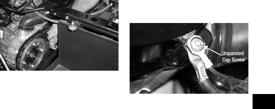
2-21
2
PR108
NOTE: At this point, the wedge can be removed
from between the driven pulley faces.
4. Rotate the V-belt and driven pulley/clutch until
the V-belt is flush with the top of the driven pul-
ley.
5. Place the V-belt cover gasket into position; then
install the cover and secure with the cap screws
making sure the different-lengthed cap screws
are in their proper location. Tighten the cap
screws to specifications.
NOTE: Make sure the main harness and engine
ground wires are installed and secured in the
proper location with the unpainted cap screw.
PR111B
6. Secure the seat-base with the four cap screws.
Tighten securely.
7. Install the seats and center console making sure
the seats lock securely.

3-1
3
SECTION 3 — ENGINE/TRANSMISSION
TABLE OF
CONTENTS
Engine/Transmission …………….…………….…………… 3-2
Specifications …..…………….…………….…………….….. 3-3
Prowler XT (Table of Contents) ……….………….…….. 3-4

3-2
Engine/Transmission
This section has been organized into sub-sections
which show a progression for the complete servic-
ing of the Arctic Cat Prowler XT engine/transmis-
sion.
To service the center crankcase halves, the
engine/transmission must be removed from the
frame.
To service top-side, left-side, and right-side compo-
nents, the engine/transmission does not have to be
removed from the frame.
NOTE: Arctic Cat recommends the use of new
gaskets, lock nuts, and seals and lubricating all
internal components when servicing the
engine/transmission.
NOTE: Some photographs and illustrations used
in this section are used for clarity purposes only
and are not designed to depict actual conditions.

3-3
3
Specifications*
* Specifications subject to change without notice.
VALVES AND GUIDES
Valve Face Diameter (intake)
(exhaust)
31.6 mm (1.24 in.)
27.9 mm (1.10 in.)
Valve/Tappet Clearance
(cold engine)
(intake)
(exhaust)
0.1016 mm (0.004 in.)
0.1524 mm (0.006 in.)
Valve Guide/Stem
Clearance
(intake)
(exhaust)
0.013 mm
(0.0005 in.)
0.013 mm
(0.0005 in.)
Valve Guide/Valve
Stem Deflection
(wobble method)
(max) 0.35 mm (0.014 in.)
Valve Guide Inside
Diameter
5.000-5.012 mm
(0.1969-0.1973 in.)
Valve Stem Outside
Diameter
(intake)
(exhaust)
4.972-4.987 mm
(0.1957-0.1963 in.)
4.972-4.987 mm
(0.1957-0.1963 in.)
Valve Stem Runout (max) 0.1 mm (0.0039 in.)
Valve Head Thickness (min) 2.3 mm (0.0906 in.)
Valve Stem End Length (min) 3.97 mm (0.156 in.)
Valve Face/Seat Width (intake)
(exhaust)
2.25 mm (0.0886 in.)
2.60 mm (0.1024 in.)
Valve Seat Angle (intake)
(exhaust)
45° 15’-45° 30’
45° 15’-45° 30’
Valve Face Radial Runout (max) 0.2 mm (0.0079 in.)
Valve Spring Free Length (min) 38.7 mm (1.524 in.)
Valve Spring Tension
@ 31.5 mm (1.24 in.)
(outer) 19.0 kg (42 lb)
CAMSHAFT AND CYLINDER HEAD
Cam Lobe Height (min) (intake)
(exhaust)
13.97 mm (0.55 in.)
13.97 mm (0.55 in.)
Camshaft Journal Oil
Clearance
(max) 0.04 mm (0.0016 in.)
Camshaft Journal Holder
Inside Diameter
(right & center)
(left)
21.98-22.04 mm
(0.8654-0.8677 in.)
17.48-17.53 mm
(0.6882-0.6902 in.)
Camshaft Journal
Outside Diameter
(right & center)
(left)
21.96-21.98 mm
(0.8646-0.8654 in.)
17.47-17.48 mm
(0.6878-0.6882 in.)
Camshaft Runout (max) 0.05 mm (0.002 in.)
Rocker Arm Inside
Diameter
12.000-12.018 mm
(0.4724-0.4731 in.)
Rocker Arm Shaft
Outside Diameter
11.97-11.98 mm
(0.4713-0.4717 in.)
Cylinder Head Distortion (max) 0.05 mm (0.002 in.)
Cylinder Head Cover
Distortion
(max) 0.05 mm (0.002 in.)
CYLINDER, PISTON, AND RINGS
Piston Skirt/Cylinder
Clearance
0.045 mm (0.0018 in.)
Cylinder Bore 98 mm (3.858 in.)
Piston Diameter
15 mm (0.6 in.) from Skirt
End
97.948-97.962 mm
(3.856-3.857 in.)
Piston Ring
Free End Gap
(1st Ring)
(2nd Ring)
12.5 mm (0.492 in.)
12.5 mm (0.492 in.)
Bore x Stroke 97.9 x 85 mm
(3.86 x 3.35 in.)
Cylinder Trueness (max) 0.01 mm (0.004 in.)
Piston Ring End Gap
— Installed
0.36 mm (0.014 in.)
Piston Ring to Groove
Clearance (max)
(1st)
(2nd)
0.03 mm
(0.0012 in.)
0.03 mm
(0.0012 in.)
Piston Ring Groove Width (1st)
(2nd)
(Oil)
1.202-1.204 mm
(0.0473-0.0474 in.)
1.202-1.204 mm
(0.0473-0.0474 in.)
2.01-2.03 mm
(0.0791-0.0799 in.)
Piston Ring Thickness (1st)
(2nd)
1.970-1.990 mm
(0.0776-0.0783 in.)
1.970-1.990 mm
(0.0776-0.0783 in.)
Piston Pin Bore (max) 23.0 mm (0.9055 in.)
Piston Pin Outside Diame-
ter
(min) 22.99 mm (0.9051 in.)
CRANKSHAFT
Connecting Rod
(small end inside diameter)
(max)
23.021 mm
(0.9063 in.)
Connecting Rod
(big end side-to-side) 0.6 mm (0.024 in.)
Connecting Rod (big end
width)
25 mm (0.9843 in.)
Connecting Rod @ 150 mm
(5.9 in.)
(small end deflection)
(max) 0.3 mm (0.0118 in.)
Crankshaft (web-to-web) 71 mm (2.79 in.)
Crankshaft Runout(max) 0.03 mm (0.0012 in.)
Oil Pressure @2500 RPM
(Cooling Fan Cycling)
1.40-2.11 kg/cm²
(20-30 psi)
Cooling Fan
Thermo-Switch
Operating Temperature
(offJon)
(onJoff)
90°C (194°F) ±10%
75°C (167°F) ±10%
Engine Coolant
Thermo-Switch
Operating Temperature
107°-113°C
(225°-235°F)
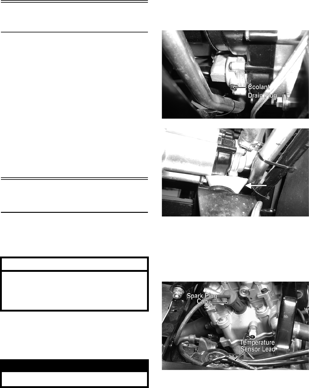
3-4
Prowler XT
(Table of Contents)
Removing Engine/Transmission ………………….……. 3-4
Top-Side Components…………….…………….…………. 3-8
Removing Top-Side Components ………..……………. 3-8
Right-Side Components …………….…………….…….. 3-12
Removing Right-Side Components………………….. 3-12
Left-Side Components ……..………….…………….….. 3-14
Removing Left-Side Components ………………..….. 3-15
Center Crankcase Components …………….……….. 3-18
Separating Crankcase Halves………….……………... 3-18
Disassembling Crankcase Half ……………………….. 3-19
Servicing Components..………….…………….……….. 3-21
Assembling Crankcase Half …………….………….….. 3-39
Joining Crankcase Halves……………….………….….. 3-42
Installing Left-Side Components ………….………….. 3-43
Installing Right-Side Components…………..……….. 3-45
Installing Top-Side Components ………….………….. 3-47
Installing Engine/Transmission……………….……….. 3-54
Removing Engine/
Transmission
Many service procedures can be performed without
removing the engine/transmission from the frame.
Closely observe the note introducing each sub-sec-
tion for this important information.
Support the vehicle on a suitable lift or jack stands
allowing room to perform work from the underside.
NOTE: Locate the jack stands to allow removing
of the center belly panel.
1. Remove the seats and center console; then
remove the left-side and right-side seat-bases.
2. Remove the center belly panel; then drain the oil
and coolant.
NOTE: Use a small funnel between the frame and
coolant drain plug to prevent coolant from drain-
ing on the frame and splashing.
PR122A
PR156A
3. Remove the negative cable from the battery;
then remove the positive cable.
4. From the right-side, remove the spark plug cap;
then disconnect the temperature sensor lead,
speed sensor connector, fuel quantity sender
lead, and reverse override switch connector.
PR130A
AT THIS POINT
If the technician‘s objective is to service/replace
left-side cover oil seals (3), front output joint oil
seal (1), rear output joint oil seal (1), and/or the
oil strainer (from beneath the engine/
transmission), the engine/transmission does not
have to be removed from the frame.
! WARNING
Make sure the vehicle is solidly supported on the
support stands to avoid injury.
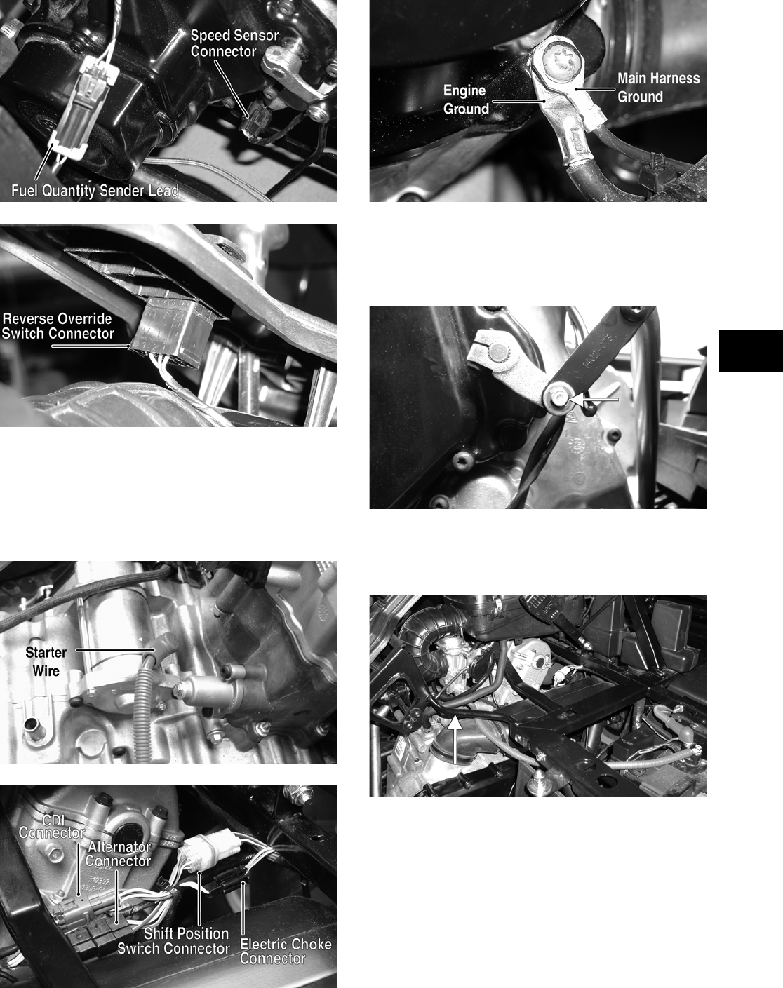
3-5
3
PR155A
PR157A
5. From the left-side, disconnect the starter wire,
alternator connector, CDI connector, shift posi-
tion switch connector, and electric choke con-
nector; then remove the cap screw securing the
main harness and the engine ground wires to the
V-belt housing.
PR145A
PR128A
PR111A
6. Remove the E-clip from the shift arm; then dis-
connect the shifter linkage. Account for three
spacer washers.
PR138A
7. Remove four machine screws securing the
shifter mount to the frame; then remove the
shifter assembly.
PR123A
8. Loosen the clamp securing the air intake boot to
the carburetor and the clamp securing the air fil-
ter housing to the inlet housing boot; then
remove the crankcase breather hose from the
crankcase.
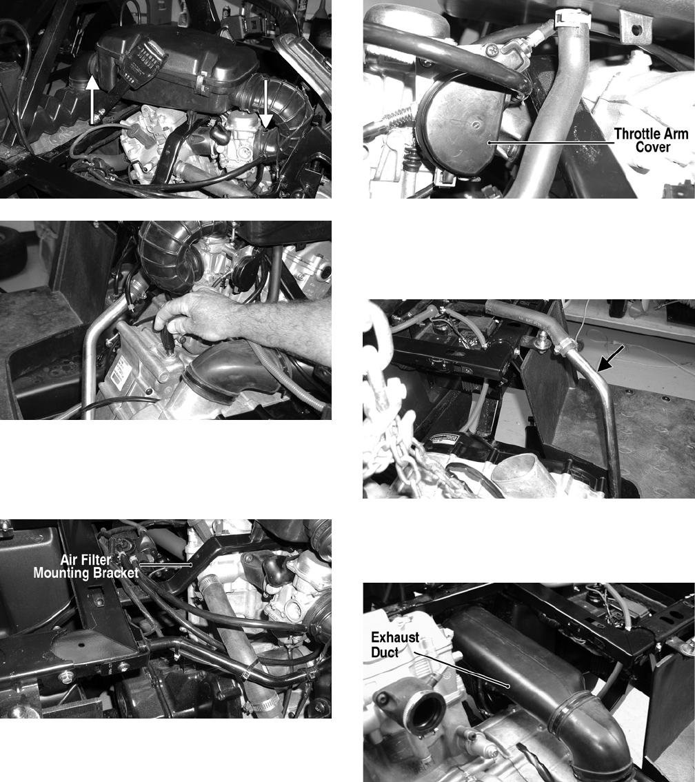
3-6
PR127A
PR118
9. Remove four self-tapping screws securing the
air filter mounting bracket to the frame; then
remove the air filter and mounting bracket as an
assembly.
PR140A
10. Remove the throttle arm cover from the carbure-
tor; then disconnect and remove the throttle
cable and the carburetor.
PR154A
11. Remove the coolant hoses from the water pump
and thermostat housings; then position the upper
coolant line to the left-side of the engine com-
partment.
PR150A
12. Remove the exhaust duct from the V-belt hous-
ing; then remove the inlet boot connecting the
inlet duct to the V-belt housing.
PR144B
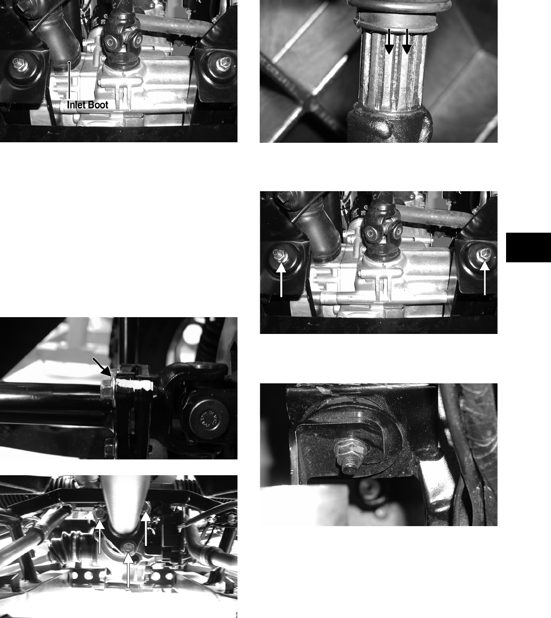
3-7
3
PR153B
13. Remove the muffler; then remove the exhaust
pipe.
14. Set the parking brake; then from the underside
of the vehicle, mark the flanges of the drive-line
couplers for assembling and remove the cap
screws (three on the front drive coupler and
three on the rear drive coupler) securing the
driveshafts to the drive couplers.
NOTE: Remove the front driveshaft first or the
parking brake will not hold the coupler stationary
and cap screw removing will be more difficult.
PR152A
PR120A
15. Separate the drive coupler flanges; then remove
the driveshafts from the splined slip-joints being
careful not to damage the rubber boots. The
front boot should be removed with the drive-
shaft.
PR148A
16. Remove two flange nuts from the underside of
the rear engine mounts.
PR153A
17. Remove two flange nuts securing the engine
mounting bracket to the front engine mounts.
PR147
18. Attach suitable lifting chains to the engine/trans-
mission; then using an engine hoist, lift the
assembly out of the engine compartment.
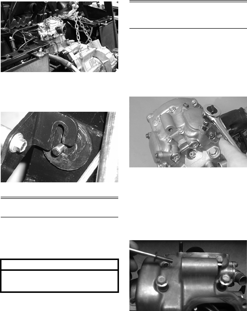
3-8
PR114
NOTE: The front engine mounting bracket
should slide free of the engine mounts first; then
the rear engine mounting bracket and two rear
engine mounts will lift free of the frame.
PR146
Top-Side Components
NOTE: For efficiency, it is preferable to remove
and disassemble only those components which
need to be addressed and to service only those
components. The technician should use discretion
and sound judgment.
NOTE: The engine/transmission does not have
to removed from the frame for this procedure.
Removing Top-Side
Components
A. Valve Cover
B. Cylinder Head
NOTE: Remove the spark plug and timing
inspection plug; then using the recoil starter,
rotate the crankshaft to top-dead-center of the
compression stroke.
1. Remove the two tappet covers.
CC001D
NOTE: Keep the mounting hardware with the
covers for assembly purposes or thread them back
into the head to keep them separated.
2. Remove the twelve cap screws securing the
valve cover to the head; account for the four
rubber washers on the top side cap screws.
Remove the valve cover. Account for and note
the orientation of the cylinder head plug. Note
the location of two alignment pins.
CD205
AT THIS POINT
To service any one specific component, only
limited disassembly of components may be
necessary. Note the AT THIS POINT information
in each sub-section.
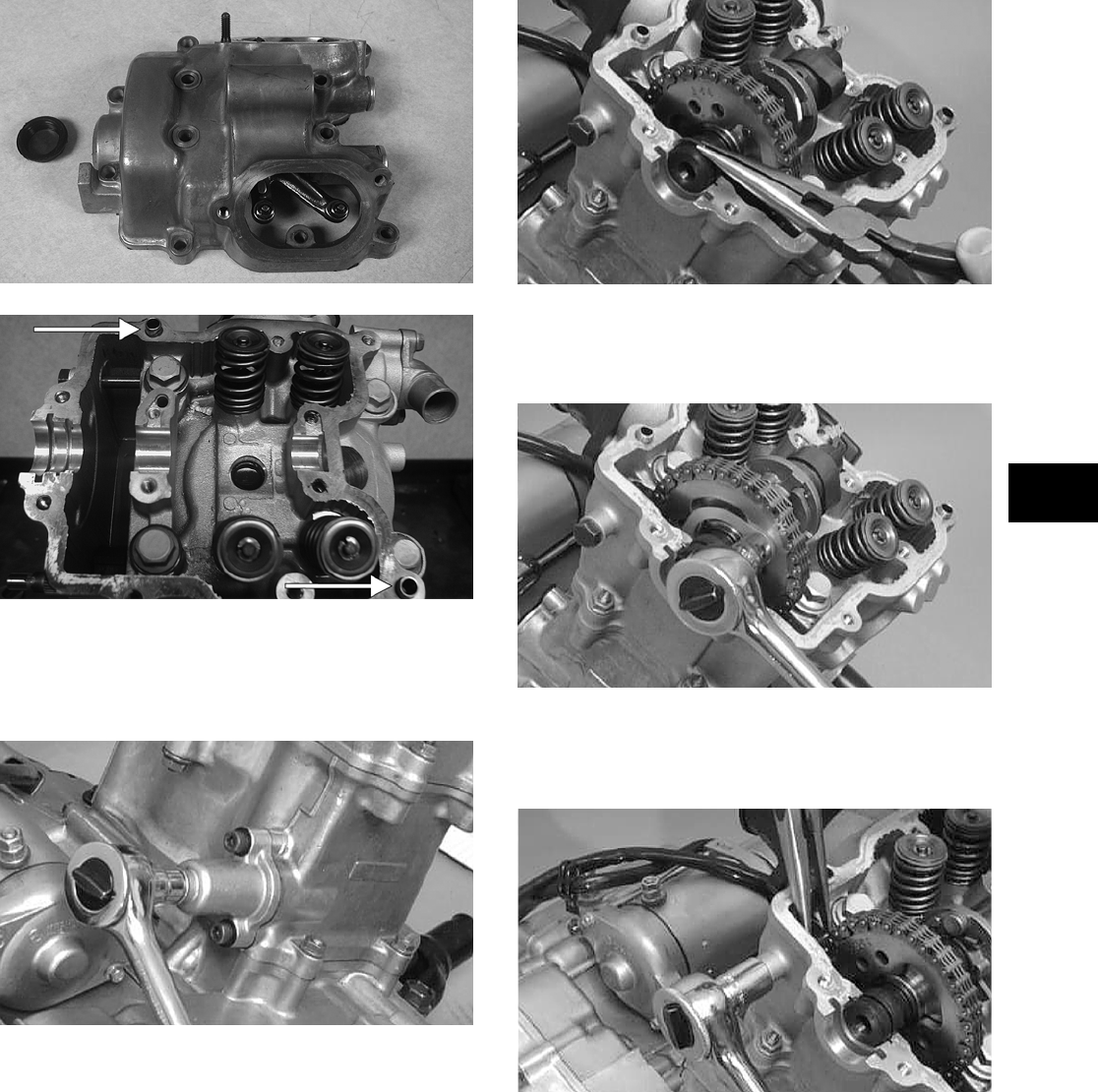
3-9
3
CD206
CD211A
3. Loosen the cap screw on the end of the ten-
sioner; then remove the two machine screws
securing the tensioner adjuster assembly and
remove the assembly. Account for a gasket.
CC009D
4. Using an awl, rotate the C-ring in its groove
until it is out of the cylinder head; then remove
the C-ring.
NOTE: Care should be taken not to drop the
C-ring down into the crankcase.
CC012D
5. Bend the washer tabs down and remove the two
cap screws securing the sprocket to the cam-
shaft; then drop the sprocket off the camshaft.
CC013D
6. Remove the cap screw securing the chain ten-
sioner (account for a washer); then remove the
tensioner.
CC014D
7. While holding the chain, slide the sprocket and
camshaft out of the cylinder head.
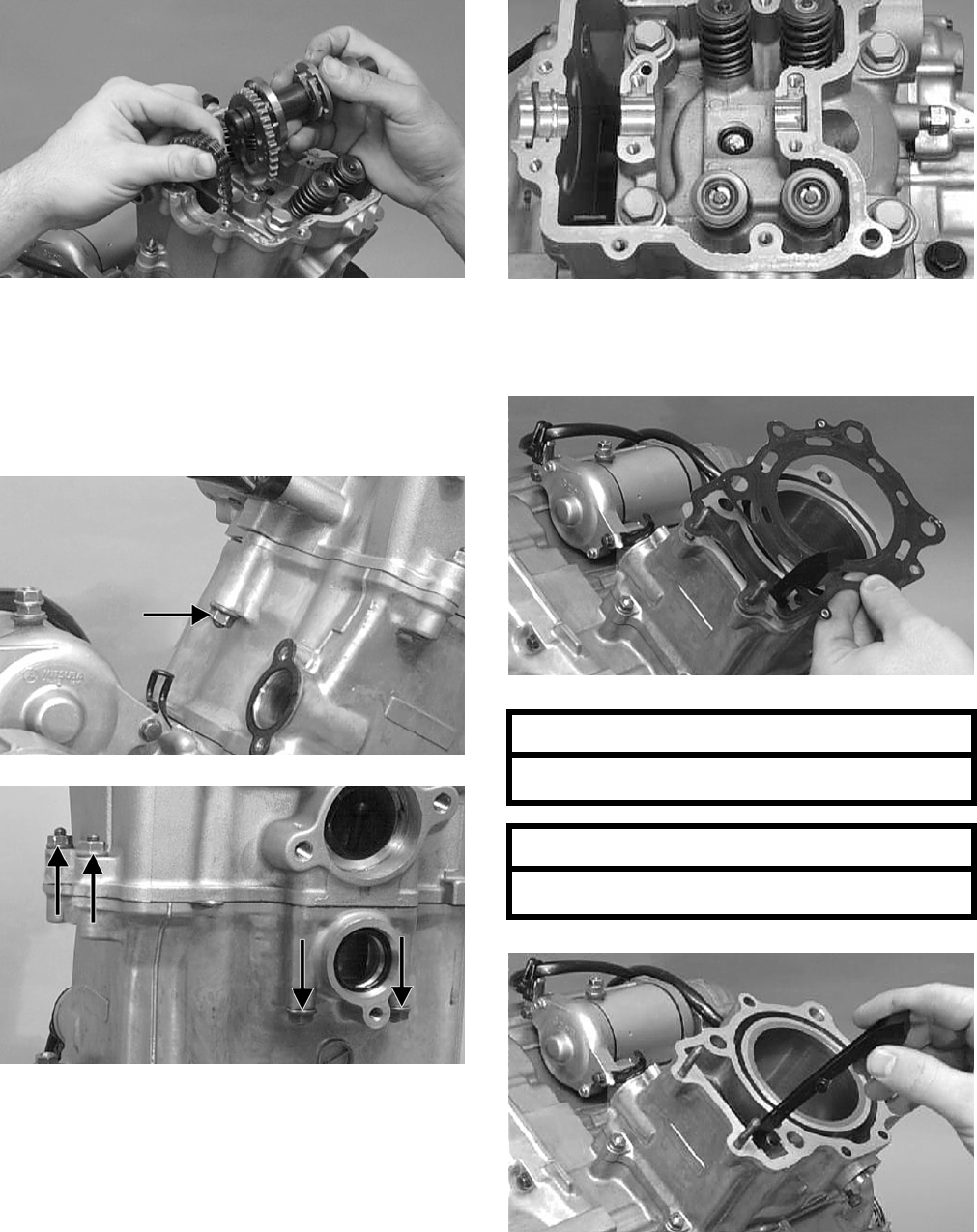
3-10
CC266D
NOTE: Loop the chain over the cylinder and
secure it to keep it from falling into the crankcase.
8. Remove the five nuts securing the cylinder head
to the cylinder; then remove the four cylinder
head cap screws with copper washers.
CC017D
CC018D
CC016D
9. Remove the cylinder head from the cylinder,
remove the gasket, and account for two align-
ment pins; then remove the cam chain guide.
CC020D
CC022D
AT THIS POINT
To service valves and cylinder head, see
Servicing Top-Side Components sub-section.
AT THIS POINT
To inspect cam chain guide, see Servicing
Top-Side Components sub-section.
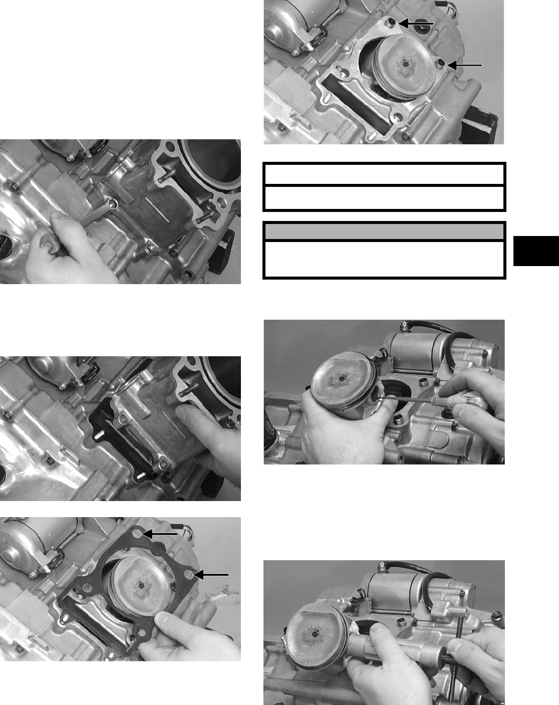
3-11
3
C. Cylinder
D. Piston
NOTE: Steps 1-9 in the preceding sub-section
must precede this procedure.
10. Loosen the clamp securing the coolant hose to
the union; then detach the hose.
11. Remove the two nuts securing the cylinder to
the crankcase.
CC023D
12. Lift the cylinder off the crankcase taking care
not to allow the piston to drop against the crank-
case. Account for the gasket and two alignment
pins.
CC024D
CC025D
CC026D
13. Using an awl, remove one piston-pin circlip.
CC032D
14. Using the Piston-Pin Puller (p/n 0644-328),
remove the piston pin. Account for the oppo—
site-side circlip. Remove the piston.
NOTE: It is advisable to remove the oppo-
site-side circlip prior to using the puller.
CC033D
AT THIS POINT
To service cylinder, see Servicing Top-Side
Components sub-section.
! CAUTION
When removing the cylinder, be sure to support the
piston to prevent damage to the crankcase and pis-
ton.
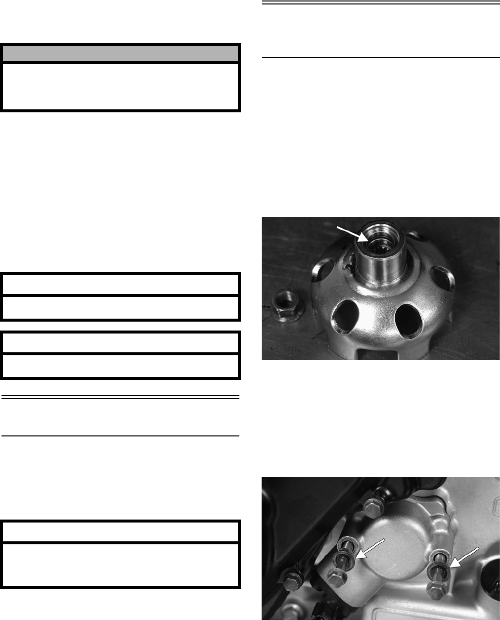
3-12
NOTE: Support the connecting rod with rubber
bands to avoid damaging the rod or install the
Connecting Rod Holder (p/n 0444-006).
NOTE: If the existing rings will not be replaced
with new rings, note the location of each ring for
proper installation. When replacing with new rings,
replace as a complete set only. If the piston rings
must be removed, remove them in this sequence.
A. Starting with the top ring, slide one end of the
ring out of the ring-groove.
B. Remove each ring by working it toward the
dome of the piston while rotating it out of the
groove.
Right-Side Components
NOTE: For efficiency, it is preferable to remove
and disassemble only those components which
need to be addressed and to service only those
components. The technician should use discretion
and sound judgment.
NOTE: The engine/transmission does not have
to be removed from the frame for this procedure.
Removing Right-Side
Components
A. Water Pump
B. Side Cover
C. Rotor/Flywheel
1. Remove the four cap screws securing the dust
cover to the right-side cover; then remove the
cover.
2. Remove the flange nut securing the starter cup
to the crankshaft; then remove the starter cup.
Account for the O-ring inside the cup.
CD925A
3. Using a cold chisel, scribe a mark showing the
relative position of the shift arm to the shift arm
shaft to aid in installing; then remove the shift
arm.
4. Remove the two machine screws securing the
speed sensor housing; then remove the housing.
Account for the gasket and two seal washers.
CD920A
5. Loosen the clamps securing the coolant hose to
the water pump; then remove the crossover tube
from the cylinder head. Account for an O-ring.
! CAUTION
Do not allow the connecting rod to go down inside
the crankcase. If the rod is down inside the crank-
case and the crankshaft is rotated, severe damage
will result.
AT THIS POINT
To service piston, see Servicing Top-Side
Components sub-section.
AT THIS POINT
To service center crankcase components only,
proceed to Removing Right-Side Components.
AT THIS POINT
To service any one specific component, only
limited disassembly of components may be
necessary. Note the AT THIS POINT information
in each sub-section.
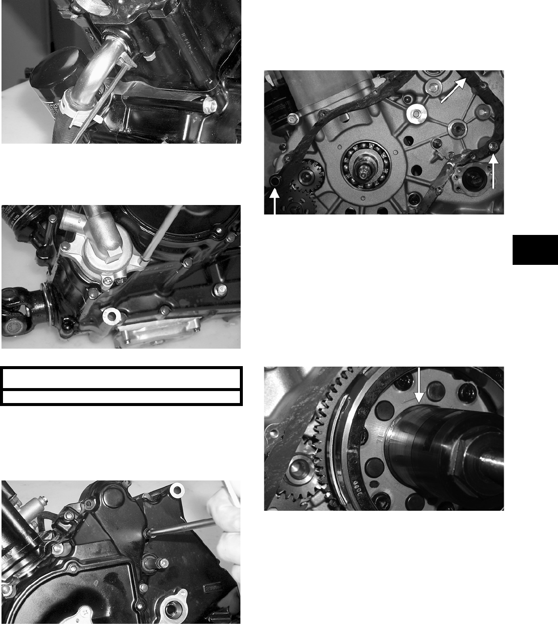
3-13
3
CC620
6. Remove the two machine screws securing the
water pump to the engine; then remove the
water pump.
CC623
7. Remove the twelve machine screws securing the
right-side cover to the crankcase noting the loca-
tion of the different-sized machine screws for
installing purposes.
CC626
8. Using Side Case Puller (p/n 0644-262), remove
the side cover. Account for a gasket and two
alignment pins.
NOTE: Inspect the inside of the left-side cover
for any shaft washers that may have come off with
the cover. Make sure they are returned to their
respective shafts and that the starter idler gear
spacer is on the shaft or in the cover.
CD942A
9. Remove the nut securing the magneto rotor to
the crankshaft; then install the magneto rotor
puller adapter.
NOTE: The puller has left-hand threads.
10. Using Magneto Rotor Remover Set (p/n
0444-075), remove the rotor/flywheel assembly
from the crankshaft. Account for the key; then
remove the starter clutch gear assembly and
washer.
CD939A
AT THIS POINT
To service the water pump, see Section 4.
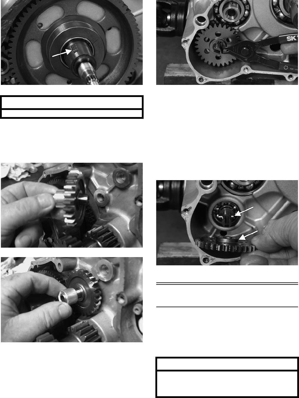
3-14
CD940A
11. Remove the two starter gears from the crankcase
noting the direction of the beveled side of the
gears for installing purposes; then remove the
two starter gear shafts.
CD140
CD138
12. Remove the snap ring securing the water pump
driven gear; then remove the gear noting the
direction of the sides of the gear for installing
purposes. Account for the driven gear alignment
pin.
CD949
NOTE: There is an oil passage beneath the
driven gear/drive gear assembly. This passage
should be plugged prior to removing the driven
gear and drive gear. Failure to do so could result in
the loss of an alignment pin into the crankcase.
13. Remove the snap ring securing the water pump
drive gear; then remove the gear noting the
direction of the sides of the gear for installing
purposes. Account for the drive gear alignment
pin.
CD952A
Left-Side Components
NOTE: For efficiency, it is preferable to remove
and disassemble only those components which
need to be addressed and to service only those
components. The technician should use discretion
and sound judgment.
NOTE: The engine/transmission does not have
to be removed from the frame for this procedure.
AT THIS POINT
To service the magneto assembly, see Section 5.
AT THIS POINT
To service any one specific component, only
limited disassembly of components may be
necessary. Note the AT THIS POINT information
in each sub-section.
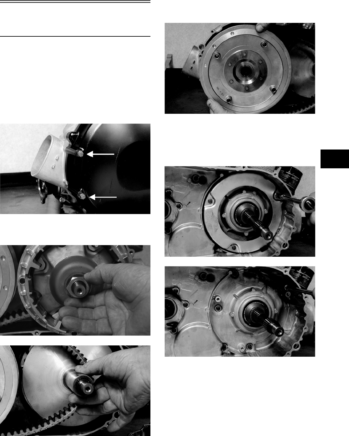
3-15
3
Removing Left-Side
Components
A. V-Belt Cover
B. Driven Pulley
C. Clutch Cover
1. Remove the machine screws securing the V-belt
cover noting the location of the differ-
ent-lengthed machine screws for installing pur-
poses; then using a rubber mallet, gently tap on
the cover tabs to loosen the cover.
CD961A
2. Remove the nut securing the movable drive
face; then remove the face. Account for a spacer.
CD962
CD964
3. Remove the V-belt.
4. Remove the nut securing the fixed driven
assembly; then remove the assembly.
CD968
5. Remove the fixed drive face.
6. Remove the machine screws securing the air
intake plate; then remove the plate/cushion
assembly.
CD970
CD972
7. Remove the machine screws securing the clutch
cover. Note the location of the differ-
ent-lengthed machine screws for installing pur-
poses. Using a rubber mallet, carefully remove
the cover. Account for two alignment pins.
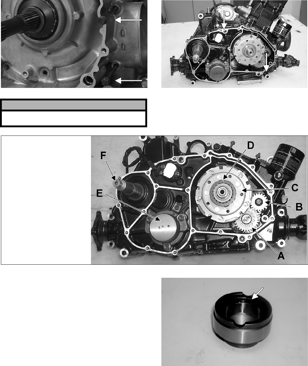
3-16
CD973A CC600A
NOTE: For steps 8-14, refer to illustration
CC829A.
CC829A
NOTE: To aid in installing, it is recommended
that the assemblies are kept together and IN
ORDER.
8. Remove the one-way clutch (D) from the clutch
housing. Note the location of the green align-
ment dot (or the word OUTSIDE) for installing
purposes.
9. Using a hydraulic press, remove the clutch hous-
ing assembly from the clutch cover. Account for
the left fixed drive spacer and an O-ring inside
the fixed drive spacer. CF085A
! CAUTION
Care must be taken when removing the cover so
the cover gasket is not damaged.
KEY
A. Oil Pump Driven Gear
B. Oil Pump Drive Gear
C. Clutch Shoe Assembly
D. One-Way Clutch
(Green Dot MUST Show)
E. Final Drive Carrier Bearing Housing
F. Input Shaft
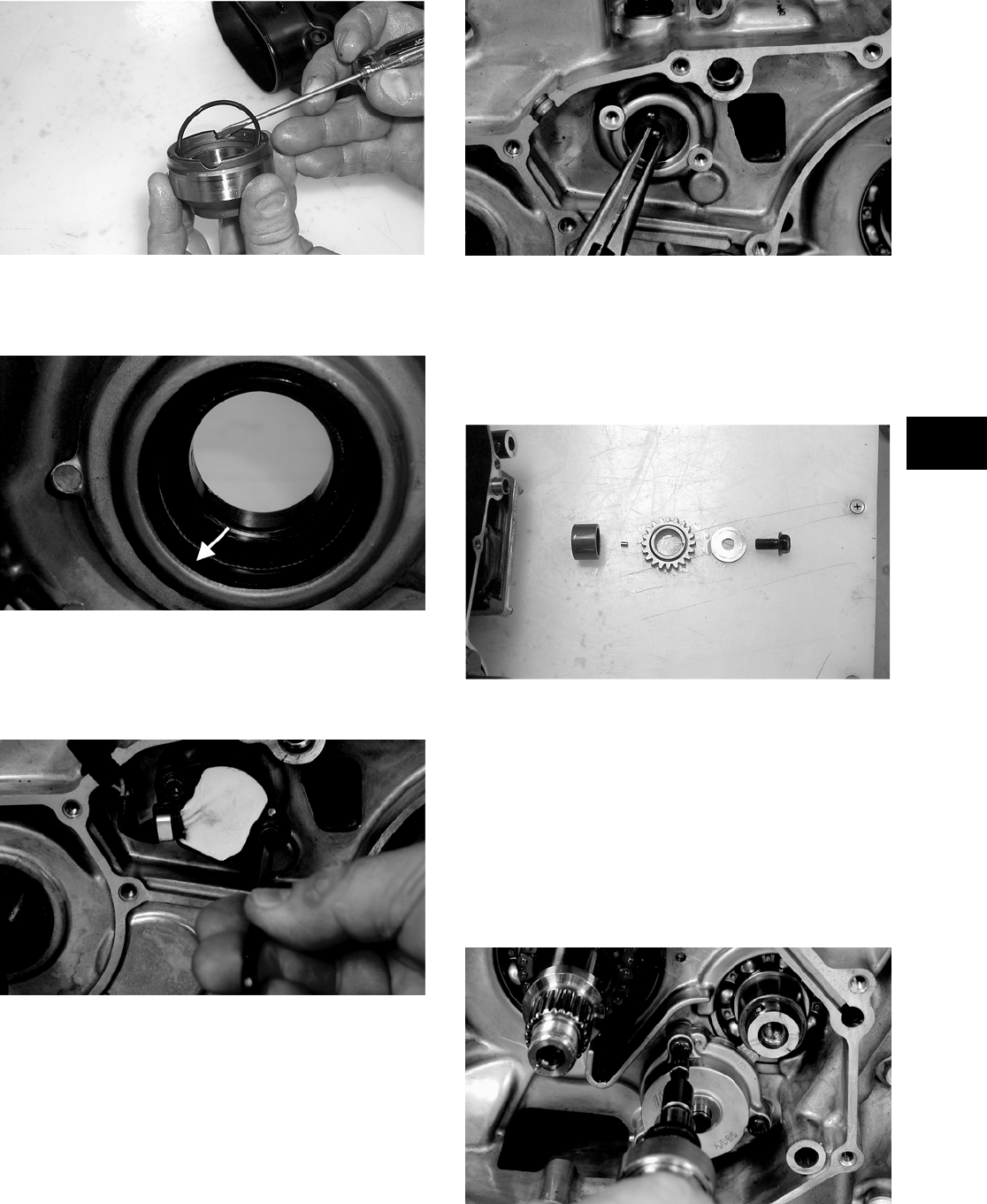
3-17
3
CC596
NOTE: Account for and inspect the clutch hous-
ing seal.
CF088A
10. Remove the two machine screws securing the
shift indicator sending unit; then remove the
unit. Account for two neutral contact pins and
two springs.
CD994
CD996
11. Remove the nut (left-hand threads) securing the
clutch shoe assembly (C).
12. Remove the cap screw securing the oil pump
drive gear (B). Account for a cap screw, washer,
pin, and spacer.
CC606
13. Remove the machine screws securing the final
drive carrier bearing housing (E); then remove
the housing and account for two alignment pins.
14. Remove the snap ring securing the oil pump
driven gear (A); then remove the gear noting the
direction of the sides of the gear for installing
purposes. Account for a pin and a washer.
15. Remove the three machine screws securing the
oil pump; then remove the pump.
CD988
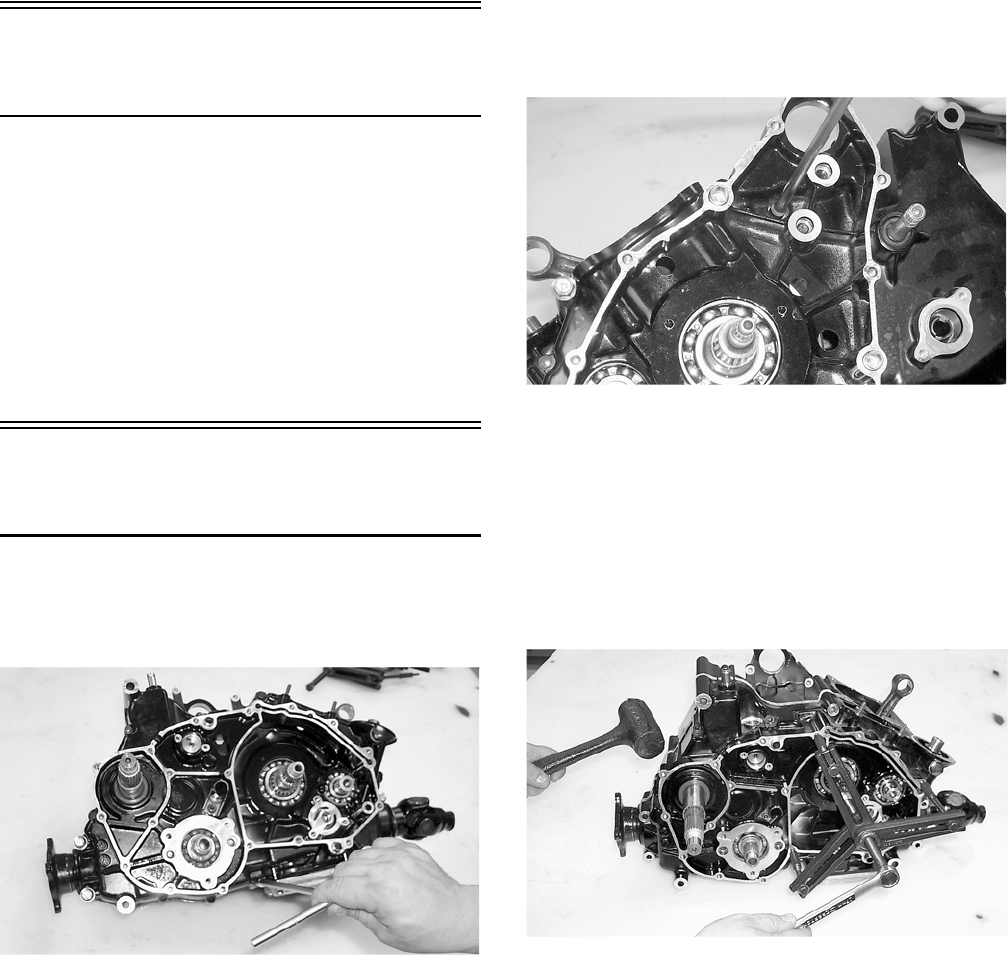
3-18
Center Crankcase
Components
NOTE: This procedure cannot be done with the
engine/transmission in the frame. Complete
Removing procedures for Top-Side, Left-Side, and
Right-Side must precede this procedure.
NOTE: For efficiency, it is preferable to remove
and disassemble only those components which
need to be addressed and to service only those
components. The technician should use discretion
and sound judgment.
Separating Crankcase
Halves
1. Remove the left-side machine screws securing
the crankcase halves. Note the location of the
different-lengthed machine screws.
CC664
2. Remove the right-side machine screws securing
the crankcase halves. Note the location of the
different-lengthed machine screws.
CC663
3. Using the Crankcase Separator/Crankshaft
Remover (p/n 0444-009) and tapping lightly
with a rubber mallet, separate the crankcase
halves. Account for four alignment pins.
NOTE: To keep the shaft/gear assemblies intact
for identification, tap the shafts toward the
right-side crankcase half when separating the
halves.
CC665
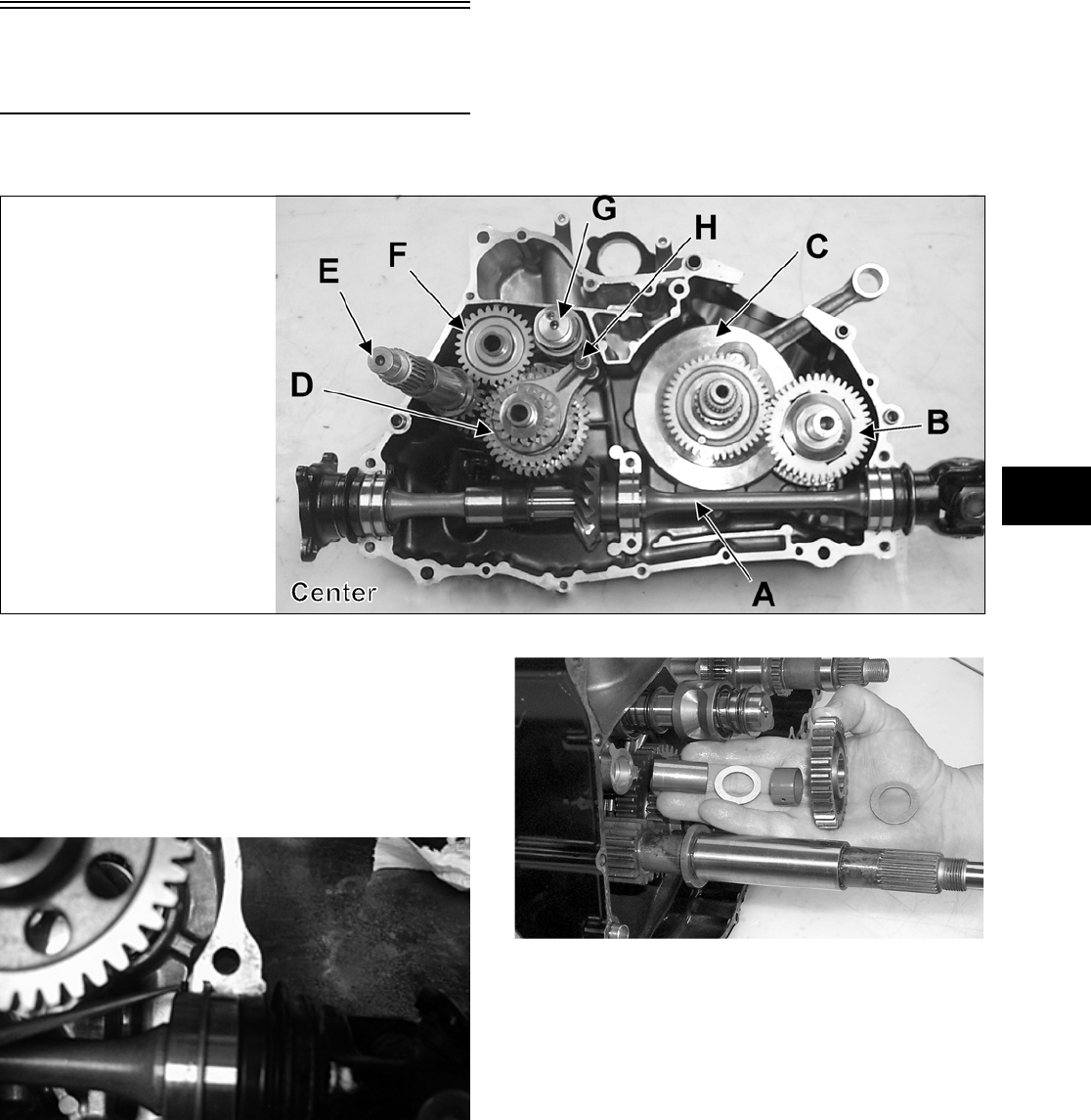
3-19
3
Disassembling
Crankcase Half
NOTE: For steps 1-7, refer to illustration CC821B.
CC821B
NOTE: To aid in installing, it is recommended
that the assemblies are kept together and IN
ORDER.
1. Remove the secondary driven shaft assembly
(A) noting the location of the bearing locating
pins. Account for the bearing C-ring.
CD267
2. Remove the reverse idler gear assembly (F).
Account for all washers, shaft, bushing, and the
gear.
CC668
3. Remove the shift shaft (H); then remove the two
forks taking note of the direction of the tabs on
the forks for assembling purposes.
4. Remove the gear shift shaft (G) noting the loca-
tion of the two holes on the end of the shaft.
Account for four washers and a needle bearing.
KEY
A. Secondary Driven Shaft Assembly
B. Crank Balancer Assembly
C. Crankshaft
D. Countershaft Assembly
E. Driveshaft
F. Reverse Idler Gear Assembly
G. Gear Shift Shaft
H. Shift Shaft with 2 Forks
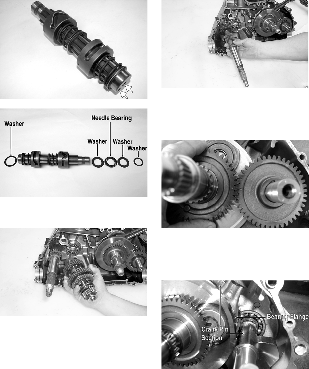
3-20
PR380A
PR381A
5. Remove the countershaft assembly (D). Account
for a washer on each end of the countershaft.
CC674
NOTE: Do not disassemble the countershaft
assembly unless necessary. If necessary, see Ser-
vicing Center Crankcase Components sub-sec-
tion.
6. Using a rubber mallet, tap on the crankcase to
remove the driveshaft.
CC675
7. Note the alignment dots on the crank balancer
assembly (B) gear and crankshaft (C) gear for
assembling purposes; then slide the crank bal-
ancer gear off the crank balancer. Account for
the key in the keyway.
CD826
8. Remove the crank balancer.
NOTE: There is a flat spot on the crank balancer
bearing flange to allow clearance past the crank-
shaft.
CD832B
9. Remove the snap ring securing the water pump
driven gear shaft.
10. Using a hydraulic press, remove the crankshaft
assembly.
NOTE: Use a protective end cap to prevent dam-
age to the crankshaft threads.
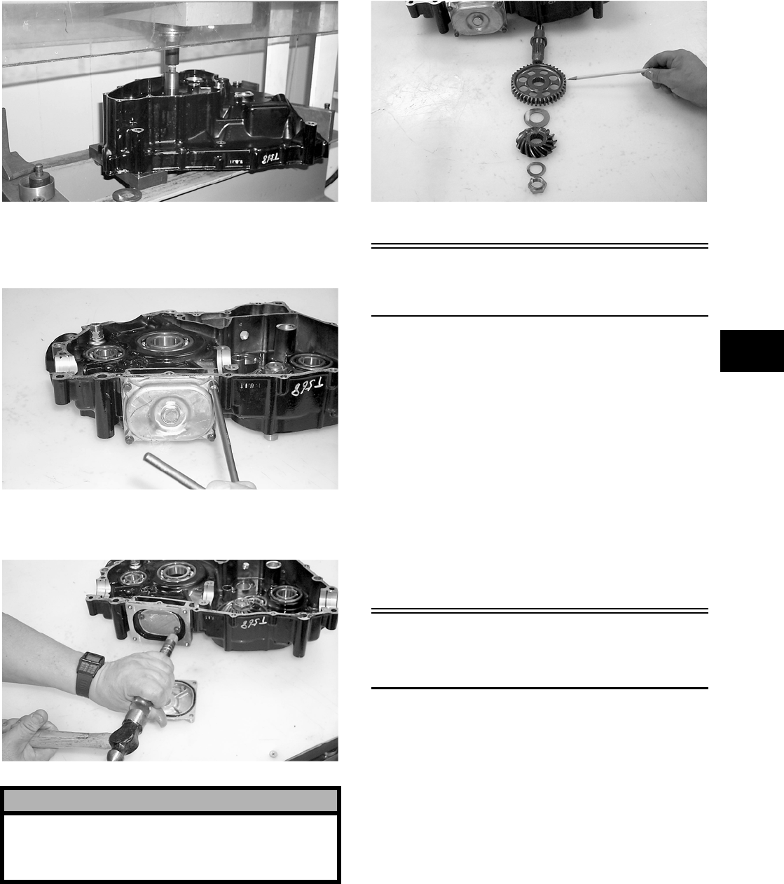
3-21
3
CC680
11. Remove the machine screws securing the oil
strainer cap; then remove the cap. Account for
the cap O-ring.
CC681
12. Remove the two machine screws securing the
oil strainer; then remove the strainer.
CC682
13. To remove the assembly, remove the nut secur-
ing the secondary drive gear and secondary
driven gear; then from the inside of the crank-
case using a rubber mallet, remove the output
shaft assembly. Account for the output shaft,
two gears, a shim, a washer, and the nut.
CC686
Table of Contents
(Servicing Components)
NOTE: Critical engine/transmission specifica-
tions are located at the beginning of this section.
Servicing Top-Side Components .…………….……… 3-21
Valve Assembly ……………….…………….…………. 3-21
Piston Assembly ..…………….………….……………. 3-26
Cylinder/Cylinder Head Assembly………………… 3-28
Servicing Left-Side Components ….…………….…… 3-31
Inspecting Centrifugal Clutch Shoe ………………. 3-31
Inspecting Clutch Housing …….…………….……… 3-31
Inspecting Primary One-Way Drive ……………… 3-31
Inspecting Oil Pump ……………….…………….…… 3-32
Driven Pulley Assembly………………………….…… 3-32
Servicing Center Crankcase Components ……….. 3-36
Secondary Gears ……….…………….…………….… 3-36
Crankshaft Assembly …………………………….…… 3-37
Countershaft ………..……………..…………….……… 3-38
Servicing Top-Side
Components
NOTE: Whenever a part is worn excessively,
cracked, or damaged in any way, replacement is
necessary.
VALVE ASSEMBLY
When servicing valve assembly, inspect valve seats,
valve stems, valve faces, and valve stem ends for
pits, burn marks, or other signs of abnormal wear.
NOTE: Whenever a valve is out of tolerance, it
must be replaced.
Cleaning/Inspecting Valve Cover
NOTE: If the valve cover cannot be trued, the cyl-
inder head assembly must be replaced.
! CAUTION
Do not remove the remaining output shaft assembly
unless absolutely necessary. If the shaft is
removed, the shaft nut must be replaced with a new
one and the shaft must be re-shimmed.
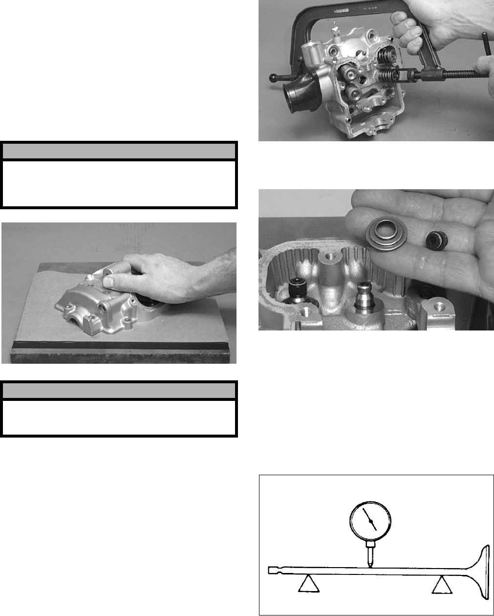
3-22
1. Wash the valve cover in parts-cleaning solvent.
2. Place the valve cover on the Surface Plate (p/n
0644-016) covered with #400 grit wet-or-dry
sandpaper. Using light pressure, move the valve
cover in a figure eight motion. Inspect the seal-
ing surface for any indication of high spots. A
high spot can be noted by a bright metallic fin-
ish. Correct any high spots before assembly by
continuing to move the valve cover in a figure
eight motion until a uniform bright metallic fin-
ish is attained.
CC130D
Removing Valves
NOTE: Keep all valves and valve components as
a set. Note the original location of each valve set
for use during installation. Return each valve set to
its original location during installation.
1. Using a valve spring compressor, compress the
valve springs and remove the valve cotters.
Account for an upper spring retainer.
CC132D
2. Remove the valve seal and the lower remaining
spring seat. Discard the valve seal.
CC136D
NOTE: The valve seals must be replaced.
3. Remove the valve springs; then invert the cylin-
der head and remove the valves.
Measuring Valve Stem Runout
1. Support each valve stem end with the V Blocks
(p/n 0644-022); then check the valve stem
runout using a dial indicator.
ATV-1082
2. Maximum runout must not exceed specifica-
tions.
! CAUTION
Do not remove an excessive amount of the sealing
surface or damage to the camshaft will result.
Always check camshaft clearance when resurfacing
the valve cover.
! CAUTION
Water or parts-cleaning solvent must be used in
conjunction with the wet-or-dry sandpaper or dam-
age to the sealing surface may result.
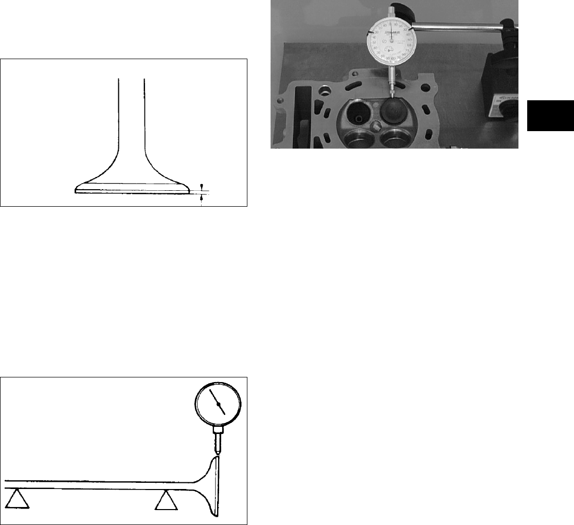
3-23
3
Measuring Valve Stem
Outside Diameter
1. Using a micrometer, measure the valve stem
outside diameter.
2. Acceptable diameter range (intake valve) must
be within specifications.
3. Acceptable diameter range (exhaust valve) must
be within specifications.
Measuring Valve Face/Seat Width
1. Using a micrometer, measure the width of the
valve face.
ATV-1004
2. Acceptable width range must be within specifi-
cations.
Measuring Valve Face Radial
Runout
1. Mount a dial indicator on the surface plate; then
place the valve stem on a set of V blocks.
2. Position the dial indicator contact point on the
outside edge of the valve face; then zero the
indicator.
ATV1082A
3. Rotate the valve in the V blocks.
4. Maximum runout must not exceed specifica-
tions.
Measuring Valve Guide/Valve Stem
Deflection (Wobble Method)
1. Mount a dial indicator and base on the surface
plate; then place the cylinder head on the surface
plate.
2. Install the valve into the cylinder head; then
position the dial indicator contact point against
the outside edge of the valve face. Zero the indi-
cator.
CC131D
3. Push the valve from side to side; then from top
to bottom.
4. Maximum “wobble” deflection must not exceed
specifications.
Measuring Valve Guide
(Inside Diameter)
1. Insert a snap gauge 1/2 way down into each
valve guide bore; then remove the gauge and
measure it with a micrometer.
2. Acceptable inside diameter range must be
within specifications.
3. If a valve guide is out of tolerance, it must be
replaced.
Replacing Valve Guide
NOTE: If a valve guide is worn or damaged, it
must be replaced.
1. If a valve guide needs replacing, insert a valve
guide remover into the valve seat side of the
valve guide. Using a hammer, gently drive the
valve guide out of the cylinder head.
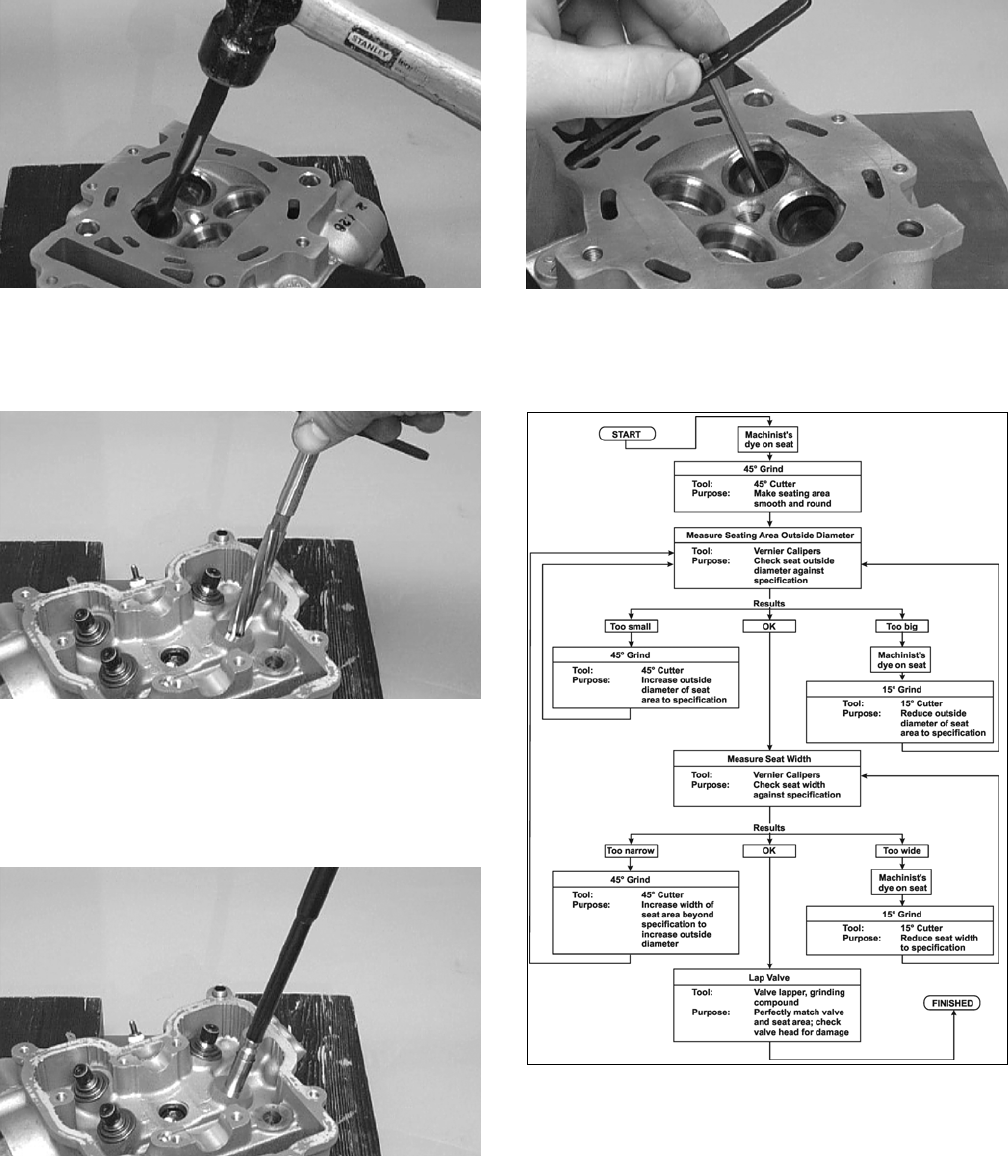
3-24
CC137D
2. Using the Standard Valve Guide Reamer (p/n
0444-017), remove any burrs or tight areas from
the valve guide journals.
CC142D
3. To install a valve guide, use a valve guide
installer and gently drive a valve guide with a
retaining clip into the bore from the valve spring
side until the retaining clip just contacts the cyl-
inder head.
CC143D
4. After installing the guide, use the standard valve
guide reamer to remove all burrs and tight areas
that may remain in each valve guide.
CC138D
Valve Seat/Guide Servicing Flow
Chart
ATV-0107
Grinding Valve Seats
NOTE: If the valve seat is beyond servicing, the
cylinder head must be replaced.
1. Insert an exhaust valve seat pilot shaft into an
exhaust valve guide. Slide an exhaust valve seat
grinding tool onto the pilot shaft; then using
light pressure on a driver handle and a deep
socket, grind the exhaust valve seat until within
specifications.
NOTE: Repeat procedure on the remaining
exhaust valve seat.
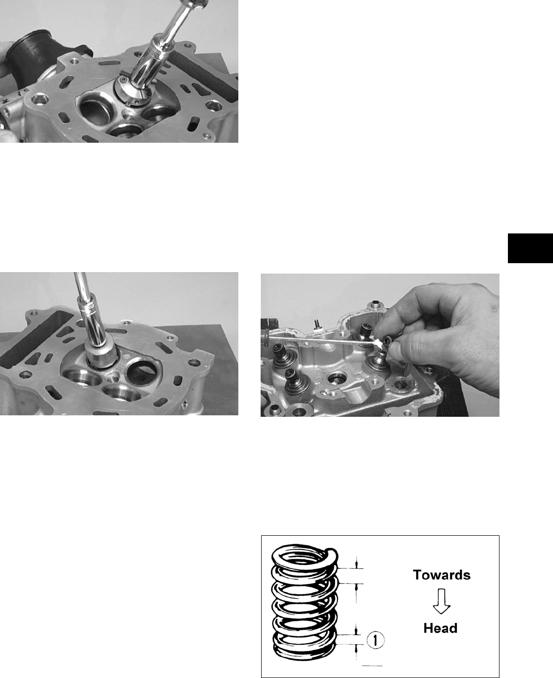
3-25
3
CC139D
2. Insert an intake valve seat pilot shaft into one of
the intake valve guides. Slide the intake valve
seat grinding tool onto the pilot shaft; then using
light pressure on a driver handle and a deep
socket, grind the intake valve seat until within
specifications.
NOTE: Repeat procedure on the remaining
intake valve seat.
CC140D
Lapping Valves
NOTE: Do not grind the valves. If a valve is dam-
aged, it must be replaced.
1. Remove all carbon from the valves.
2. Lubricate each valve stem with light oil; then
apply a small amount of valve lapping com-
pound to the entire seating face of each valve.
3. Attach the suction cup of a valve lapping tool to
the head of the valve.
4. Rotate the valve until the valve and seat are
evenly polished.
5. Clean all compound residue from the valve and
seat.
Measuring Rocker Arm
(Inside Diameter)
1. Using a dial calipers, measure the inside diame-
ter of the rocker arm.
2. Acceptable inside diameter range must be
within specifications.
Measuring Rocker Arm Shaft
(Outside Diameter)
1. Using a micrometer, measure the outside diame-
ter of the rocker arm shaft.
2. Acceptable outside diameter range must be
within specifications.
Installing Valves
1. Apply grease to the inside surface of the valve
seals; then place a lower spring seat and valve
guide seal over each valve guide.
CC144D
2. Insert each valve into its original valve location.
3. Install the valve springs with the painted end of
the spring facing away from the cylinder head.
NOTE: If the painted end is not visible, install the
ends of the springs with the closest coils toward
the head.
ATV-1011A
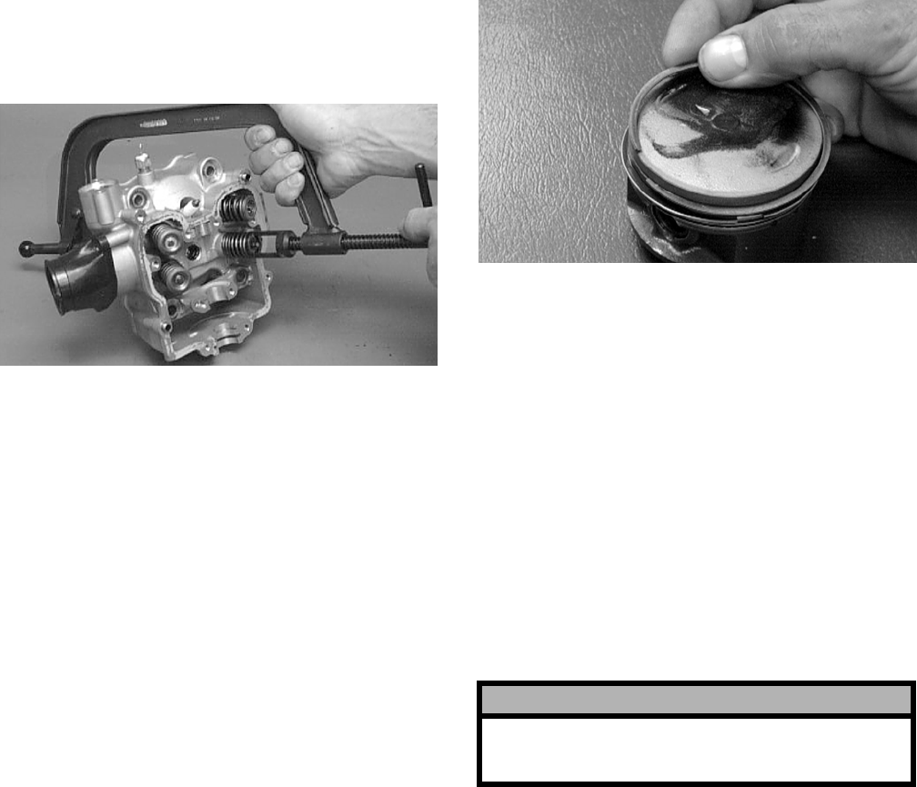
3-26
4. Place a spring retainer over the valve springs;
then using the valve spring compressor, com-
press the valve springs and install the valve cot-
ters.
CC132D
PISTON ASSEMBLY
NOTE: Whenever a piston, rings, or pin are out
of tolerance, they must be replaced.
Cleaning/Inspecting Piston
1. Using a non-metallic carbon removal tool,
remove any carbon buildup from the dome of
the piston.
2. Inspect the piston for cracks in the piston pin,
dome, and skirt areas.
3. Inspect the piston for seizure marks or scuffing.
Repair with #400 grit wet-or-dry sandpaper and
water or honing oil.
NOTE: If scuffing or seizure marks are too deep
to correct with the sandpaper, replace the piston.
4. Inspect the perimeter of each piston for signs of
excessive “blowby.” Excessive “blowby” indi-
cates worn piston rings or an out-of-round cylin-
der.
Removing Piston Rings
1. Starting with the top ring, slide one end of the
ring out of the ring-groove.
CC400D
2. Remove each ring by working it toward the
dome of the piston while rotating it out of the
groove.
NOTE: If the existing rings will not be replaced
with new ones, note the location of each ring for
proper installation. When installing new rings,
install as a complete set only.
Cleaning/Inspecting Piston Rings
1. Take an old piston ring and snap it into two
pieces; then grind the end of the old ring to a 45°
angle and to a sharp edge.
2. Using the sharpened ring as a tool, clean carbon
from the ring-grooves. Be sure to position the
ring with its tapered side up.
Measuring Piston-Ring End Gap
(Installed)
1. Place each compression ring in the wear portion
of the cylinder. Use the piston to position each
ring squarely in the cylinder.
2. Using a feeler gauge, measure each piston-ring
end gap. Acceptable ring end gap must be
within specifications.
! CAUTION
Improper cleaning of the ring-grooves by the use of
the wrong type of ring-groove cleaner will result in
severe damage to the piston.
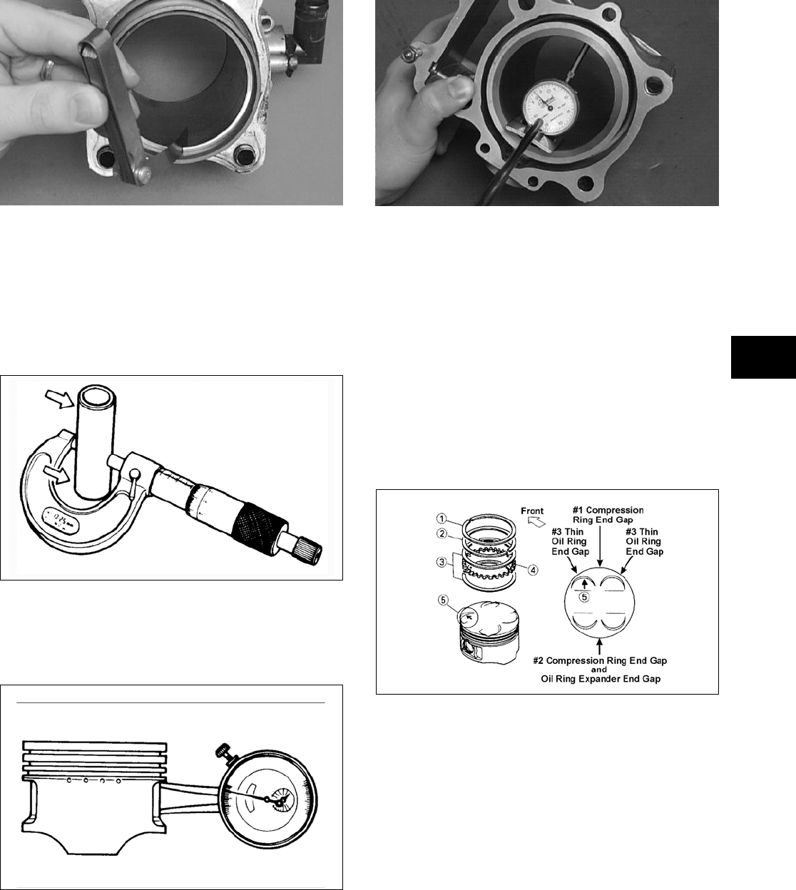
3-27
3
CC280D
Measuring Piston Pin (Outside
Diameter) and Piston-Pin Bore
1. Measure the piston pin outside diameter at each
end and in the center. If measurement is not
within specifications, the piston pin must be
replaced.
ATV-1070
2. Insert an inside dial indicator into the piston-pin
bore. The diameter must not exceed specifica-
tions. Take two measurements to ensure accu-
racy.
ATV-1069
Measuring Piston Skirt/
Cylinder Clearance
1. Measure the cylinder front to back in six places.
CC127D
2. Measure the corresponding piston diameter at a
point 15 mm (0.6 in.) above the piston skirt at a
right angle to the piston-pin bore. Subtract this
measurement from the measurement in step 1.
The difference (clearance) must be within speci-
fications.
Installing Piston Rings
1. Install ring expander (4) in the bottom groove of
the piston; then install the thin oil rings (3) over
the expander making sure the expander ends do
not overlap. Stagger the end gaps of the upper
and lower thin oil rings according to the illustra-
tion.
ATV-1085B
NOTE: Note the direction of the exhaust side of
the piston (5) for correct ring end gap orientation.
2. Install the compression ring with the orientation
mark (MTOP) in the 2nd (middle) ring groove
and the ring with the orientation mark (M) in the
1st (top) ring groove.
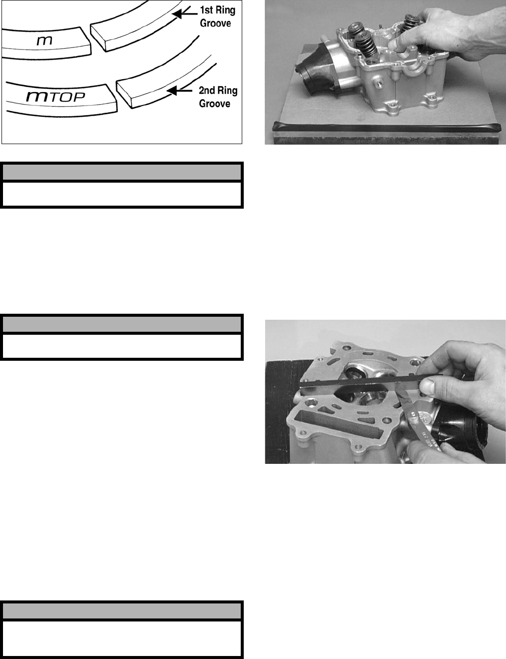
3-28
ATV-1024A
CYLINDER/CYLINDER HEAD
ASSEMBLY
NOTE: If the cylinder/cylinder head assembly
cannot be trued, they must be replaced.
Cleaning/Inspecting Cylinder Head
1. Using a non-metallic carbon removal tool,
remove any carbon buildup from the combus-
tion chamber being careful not to nick, scrape,
or damage the combustion chamber or the seal-
ing surface.
2. Inspect the spark plug hole for any damaged
threads. Repair damaged threads using a
“heli-coil” insert.
3. Place the cylinder head on the surface plate cov-
ered with #400 grit wet-or-dry sandpaper. Using
light pressure, move the cylinder head in a fig-
ure eight motion. Inspect the sealing surface for
any indication of high spots. A high spot can be
noted by a bright metallic finish. Correct any
high spots before assembly by continuing to
move the cylinder head in a figure eight motion
until a uniform bright metallic finish is attained.
CC128D
Measuring Cylinder Head
Distortion
1. Remove any carbon buildup in the combustion
chamber.
2. Lay a straightedge across the cylinder head; then
using a feeler gauge, check the distortion factor
between the head and the straightedge.
3. Maximum distortion must not exceed specifica-
tions.
CC141D
Cleaning/Inspecting Cylinder
1. Wash the cylinder in parts-cleaning solvent.
2. Inspect the cylinder for pitting, scoring, scuff-
ing, warpage, and corrosion. If marks are found,
repair the surface using a cylinder hone (see
Honing Cylinder in this sub-section).
! CAUTION
Incorrect installation of the piston rings will result
in engine damage.
! CAUTION
The cylinder head studs must be removed for this
procedure.
! CAUTION
Water or parts-cleaning solvent must be used in
conjunction with the wet-or-dry sandpaper or dam-
age to the sealing surface may result.
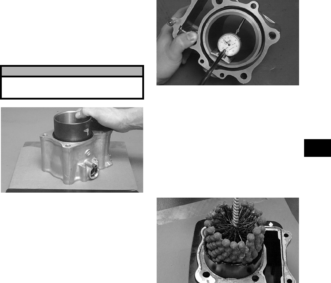
3-29
3
3. Place the cylinder on the surface plate covered
with #400 grit wet-or-dry sandpaper. Using light
pressure, move the cylinder in a figure eight
motion. Inspect the sealing surface for any indi-
cation of high spots. A high spot can be noted by
a bright metallic finish. Correct any high spots
before assembly by continuing to move the cyl-
inder in a figure eight motion until a uniform
bright metallic finish is attained.
CC129D
Inspecting Cam Chain Guide
1. Inspect cam chain guide for cuts, tears, breaks,
or chips.
2. If the chain guide is damaged, it must be
replaced.
Honing Cylinder
1. Using a slide gauge and a dial indicator or a
snap gauge, measure the cylinder bore diameter
in three locations from top to bottom and again
from top to bottom at 90° from the first mea-
surements for a total of six measurements. The
trueness (out-of-roundness) is the difference
between the highest and lowest reading. Maxi-
mum trueness (out-of-roundness) must not
exceed specifications.
CC127D
2. Wash the cylinder in parts-cleaning solvent.
3. Inspect the cylinder for pitting, scoring, scuff-
ing, and corrosion. If marks are found, repair the
surface using a ball hone.
NOTE: To produce the proper 60° cross-hatch
pattern, use a low RPM drill (600 RPM) at the rate
of 30 strokes per minute. If honing oil is not avail-
able, use a lightweight petroleum-based oil. Thor-
oughly clean cylinder after honing using soap and
hot water. Dry with compressed air; then immedi-
ately apply oil to the cylinder bore. If the bore is
severely damaged or gouged, replace the cylinder.
CC390D
4. If any measurement exceeds the limit, replace
the cylinder and piston.
Measuring Camshaft Runout
NOTE: If the camshaft is out of tolerance, it must
be replaced.
1. Place the camshaft on a set of V blocks; then
position the dial indicator contact point against
the shaft and zero the indicator.
! CAUTION
Water or parts-cleaning solvent must be used in
conjunction with the wet-or-dry sandpaper or dam-
age to the sealing surface may result.
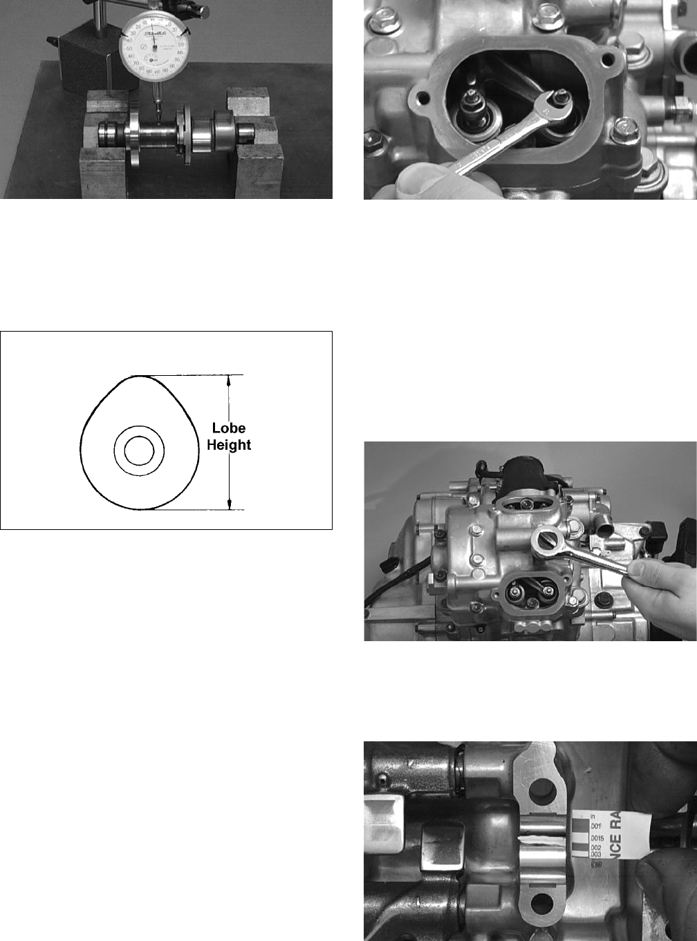
3-30
CC283D
2. Rotate the camshaft and note runout; maximum
tolerance must not exceed specifications.
Measuring Camshaft Lobe Height
1. Using a calipers, measure each cam lobe height.
ATV1013A
2. The lobe heights must not be less than minimum
specifications.
Inspecting Camshaft Bearing
Journal
1. Inspect the bearing journal for scoring, seizure
marks, or pitting.
2. If excessive scoring, seizure marks, or pitting is
found, the cylinder head assembly must be
replaced.
Measuring Camshaft to
Cylinder Head Clearance
1. Remove the adjuster screws and jam nuts.
CC005D
2. Place a strip of plasti-gauge in each of the cam-
shaft lands in the cylinder head.
3. Place the valve cover on the cylinder head and
secure with the valve cover cap screws. Tighten
securely.
NOTE: Do not rotate the camshaft when measur-
ing clearance.
4. Remove the cap screws securing the valve cover
to the cylinder; then remove the valve cover and
camshaft.
CC003D
5. Match the width of the plasti-gauge with the
chart found on the plasti-gauge packaging to
determine camshaft to cylinder head and valve
cover clearance.
CC145D
6. If clearance is excessive, measure the journals of
the camshaft.
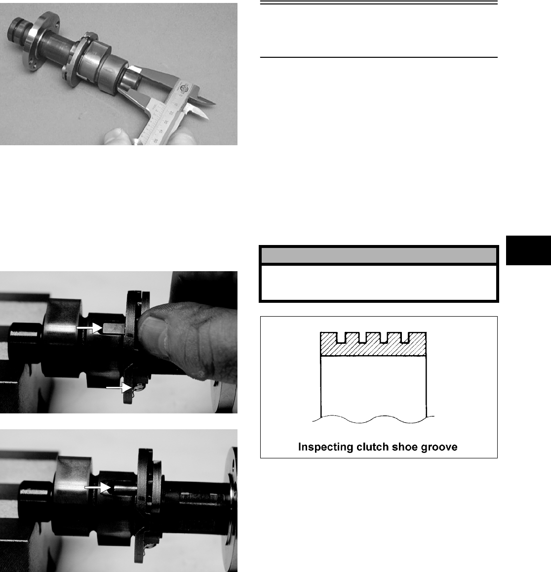
3-31
3
CC287D
NOTE: If the journals are worn, replace the cam-
shaft; then measure the clearance again. If it is still
out of tolerance, replace the cylinder head.
Inspecting Camshaft Spring/Drive
Pin
1. Inspect the spring and drive pin for damage.
CF061A
CF060A
2. If damaged, the camshaft must be replaced.
Servicing Left-Side
Components
NOTE: Whenever a part is worn excessively,
cracked, damaged in any way, or out of tolerance,
replacement is necessary.
INSPECTING CENTRIFUGAL
CLUTCH SHOE
1. Inspect the shoe for uneven wear, chips, cracks,
or discoloration. If any shoe is damaged, the
complete set must be replaced.
2. Inspect the shoe for wear or damage. If any
shoe is worn to the bottom of the groove, the
complete set must be replaced.
ATV1014
INSPECTING CLUTCH HOUSING
1. Inspect the housing for discoloration, marks,
scuffs, cracks, scratches, or uneven wear.
2. If the housing is damaged in any way, the hous-
ing must be replaced.
INSPECTING PRIMARY
ONE-WAY DRIVE
1. Insert the drive into the clutch housing.
2. Rotate the inner race by hand and verify the
inner race rotates only one direction.
3. If the inner race is locked in place or rotates both
directions, the drive assembly must be replaced.
! CAUTION
Always replace centrifugal clutch shoes as a com-
plete set or severe imbalance of the clutch assem-
bly could occur.
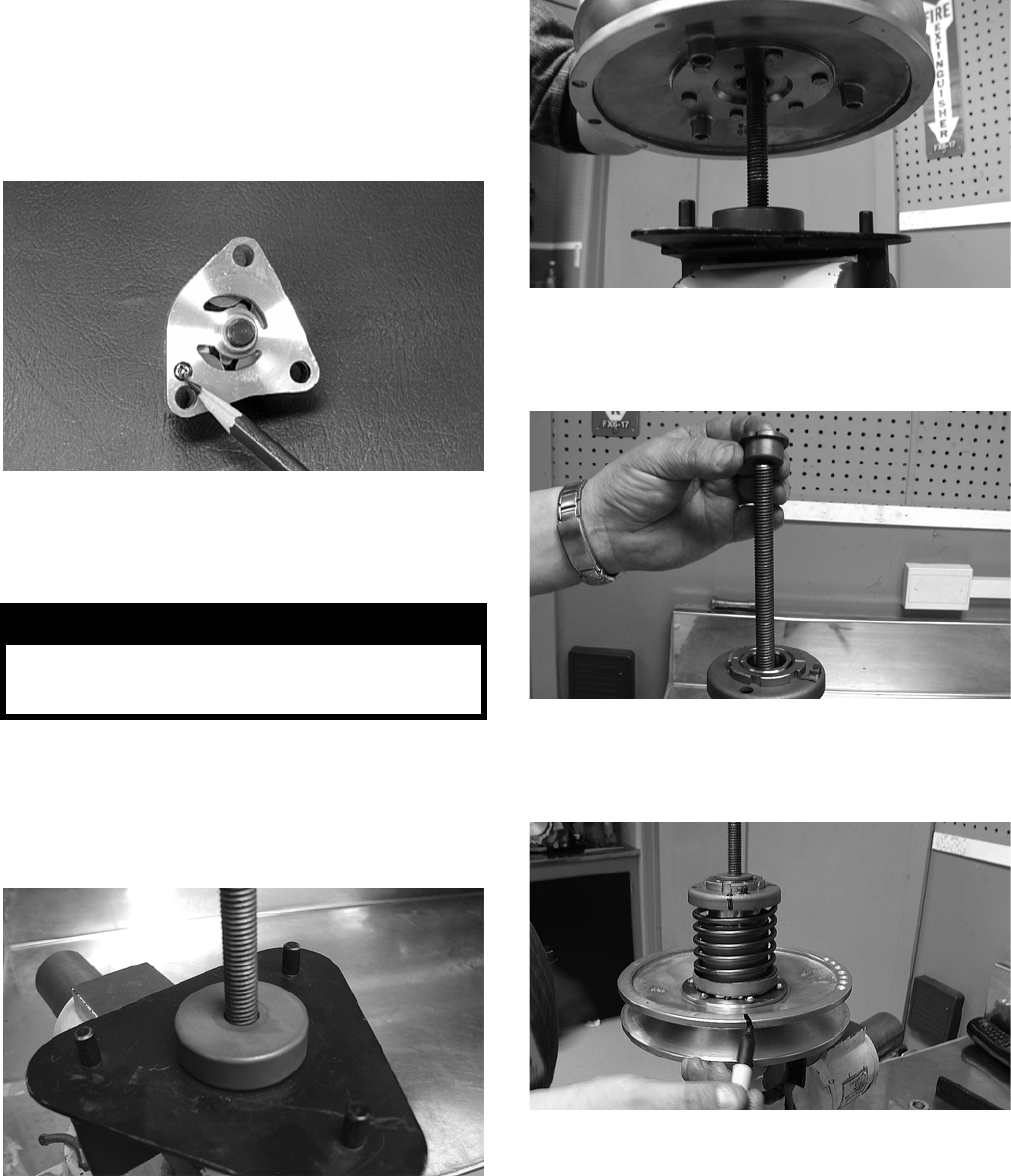
3-32
INSPECTING OIL PUMP
1. Inspect the pump for damage.
2. It is inadvisable to remove the screw securing
the pump halves. If the oil pump is damaged, it
must be replaced.
CC446D
DRIVEN PULLEY ASSEMBLY
Disassembling
1. Secure Driven Pulley Compressor (p/n
0444-121) in a suitable holding fixture such as a
bench vise; then remove the wing nut, holding
handle, flat washer, and pilot bushing leaving
the large spacer on the compressor tool base.
CD047
2. Place the driven pulley assembly onto the com-
pressor tool base engaging the dowel pins into
appropriate holes in the fixed face of the assem-
bly.
CD048
3. Install the pilot bushing with the machined end
directed down; then fit the bushing into the pul-
ley hub.
CD067
4. Using a suitable marking pen, make alignment
marks on the fixed face spring holder and both
pulley faces.
CD049
5. Place the holding handle on the spring holder
fitting the two dowel pins into the spring holder
face; then install a flat washer and the wing nut.
Turn the wing nut down until resistance is felt.
NOTE: Do not use the wing nut to compress the
spring further.
! WARNING
This procedure involves relaxing a compressed
spring assembly. DO NOT attempt disassembling
without the proper tools.
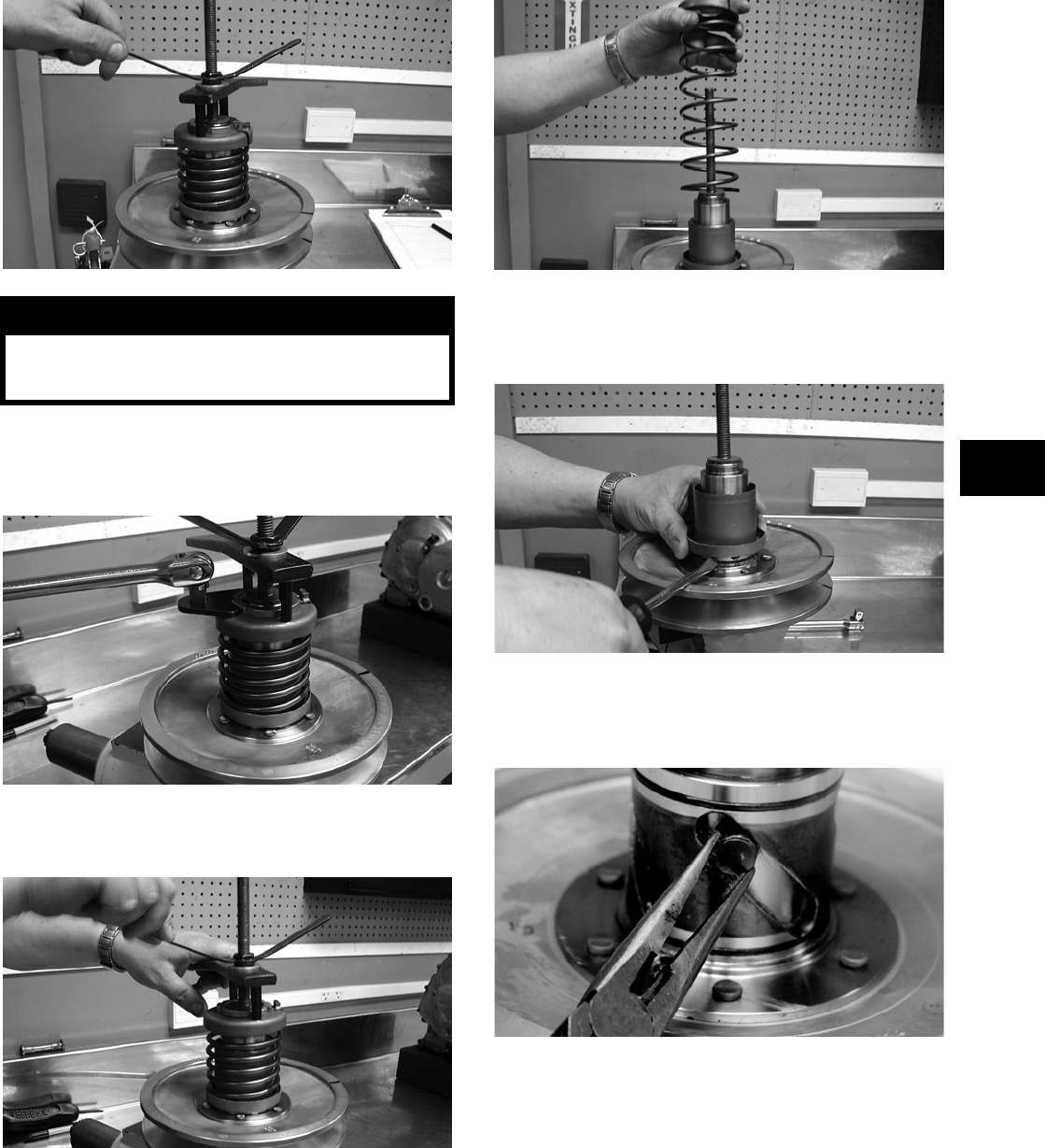
3-33
3
CD050
6. Using a spanner and suitable breaker bar, loosen
the notched-ring nut; then spin the nut free of
the hub.
CD051
7. Firmly hold the handle and slowly turn the wing
nut counterclockwise to relax the spring.
CD052
8. Continue to relax the spring until the wing nut is
flush with the end of the threads.
9. Firmly holding the spring and spring holder,
remove the wing nut; then remove the spring.
CD053A
10. Using a thin pry-bar or screwdriver, work the
movable face sleeve upward and free of the
O-rings; then remove the sleeve.
CD054
11. Remove the four pins and spacers from the cam
slots in the movable face; then remove the mov-
able face.
CF091
! WARNING
The spring assembly is under pressure. Extreme
care must be taken when relaxing the spring.
Always wear safety glasses. Use proper tools only.
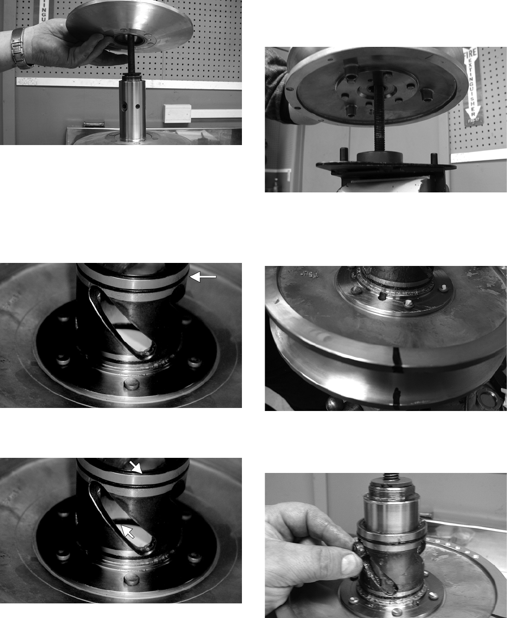
3-34
CD056
Inspecting
1. Inspect the pulley faces for wear, galling, or
grooving.
2. Inspect the O-rings on the movable face for
nicks, tears, or swelling.
CF092A
3. Inspect two grease seals in the movable face for
nicks, cuts, or damage.
CF095A
4. Inspect the pins and bushings for wear, flat
spots, looseness, or cracking.
Assembling
1. Place the fixed face of the driven pulley on the
pulley compressor base making sure the dowel
pins are engaged in the appropriate holes in the
pulley face.
NOTE: Make sure the spacer is on the base or
damage to the fixed face will occur when the
spring is compressed.
CD048
2. Apply multi-purpose grease to the O-rings and
grease seals on the movable face; then install on
the fixed face making sure the alignment marks
are properly aligned.
CD060
3. Install the four pins and spacers into the fixed
face hub; then pack the cam slots in the movable
face with multi-purpose grease.
CD061
4. Install the spring over the hub and movable face
sleeve.
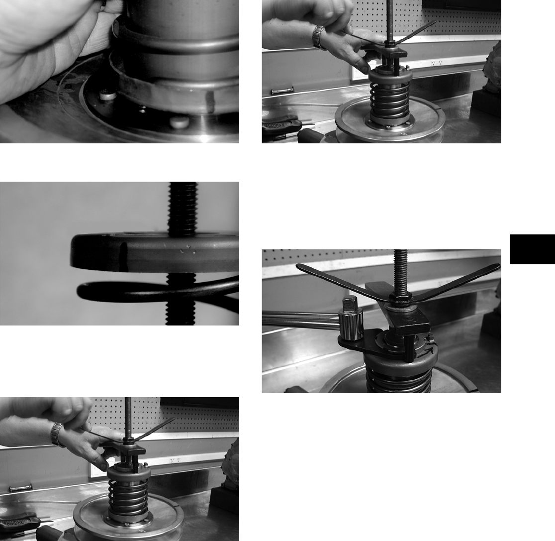
3-35
3
CF089
5. Place the spring holder on the spring.
CF087B
6. Assemble the notched-ring nut, spring holding
handle, one flat washer, and the wing nut in
order on the pulley compressor bolt; then thread
the wing nut onto the bolt.
CD052
7. Compress the spring until the spring holder
nears the threads on the fixed face hub.
CD052
8. Continue compressing the spring while guiding
the spring holder onto the hub. When a slight
resistance is felt, stop turning the wing nut.
9. Install the nut (threads coated with red Loctite
#271); then tighten the nut to specification using
the spanner and a torque wrench.
CD066
10. Remove the wing nut, washer, and holding han-
dle; then remove the driven pulley from the pul-
ley compressor.
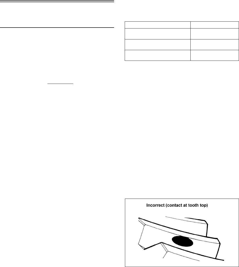
3-36
Servicing Center
Crankcase Components
NOTE: Whenever a part is worn excessively,
cracked, damaged in any way, or out of tolerance,
replacement is necessary.
SECONDARY GEARS
NOTE: All references to front or rear and left-side
or right-side are based on the orientation of the
engine/transmission as installed in this vehicle.
NOTE: When checking and correcting secondary
gear backlash and tooth contact, the universal
joint must be secured to the rear shaft or false
measurements will occur.
Checking Backlash
NOTE: Always start with the original shims on
the rear shaft.
1. Place the left-side crankcase cover onto the
left-side crankcase half to prevent runout of the
secondary transmission output shaft.
2. Install the secondary driven output shaft assem-
bly onto the crankcase.
3. Mount the dial indicator so the tip is contacting
a tooth on the secondary driven bevel gear.
4. While rocking the driven bevel gear back and
forth, note the maximum backlash reading on
the gauge.
5. Acceptable backlash range is 0.05-0.33 mm
(0.002-0.013 in.).
Correcting Backlash
NOTE: If backlash measurement is within the
acceptable range, no correction is necessary.
1. If backlash measurement is less than specified,
remove an existing shim, measure it, and install
a new thinner shim.
2. If backlash measurement is more than specified,
remove an existing shim, measure it, and install
a thicker shim.
NOTE: Continue to remove, measure, and install
until backlash measurement is within tolerance.
Note the following chart.
Checking Tooth Contact
NOTE: After correcting backlash of the second-
ary driven bevel gear, it is necessary to check
tooth contact.
1. Remove the secondary driven output shaft
assembly from the left-side crankcase half.
2. Clean the secondary driven bevel gear teeth of
old oil and grease residue.
3. Apply a thin, even coat of a machinist-layout
dye to several teeth of the gear.
4. Install the secondary driven output shaft assem-
bly.
5. Rotate the secondary driven bevel gear several
revolutions in both directions.
6. Examine the tooth contact pattern in the dye and
compare the pattern to the illustrations.
ATV-0103
Backlash Measurement Shim Correction
Under 0.05 mm (0.002 in.) Decrease Shim
Thickness
At 0.05-0.33 mm
(0.002-0.013 in.)
No Correction Required
Over 0.33 mm (0.013 in.) Increase Shim
Thickness
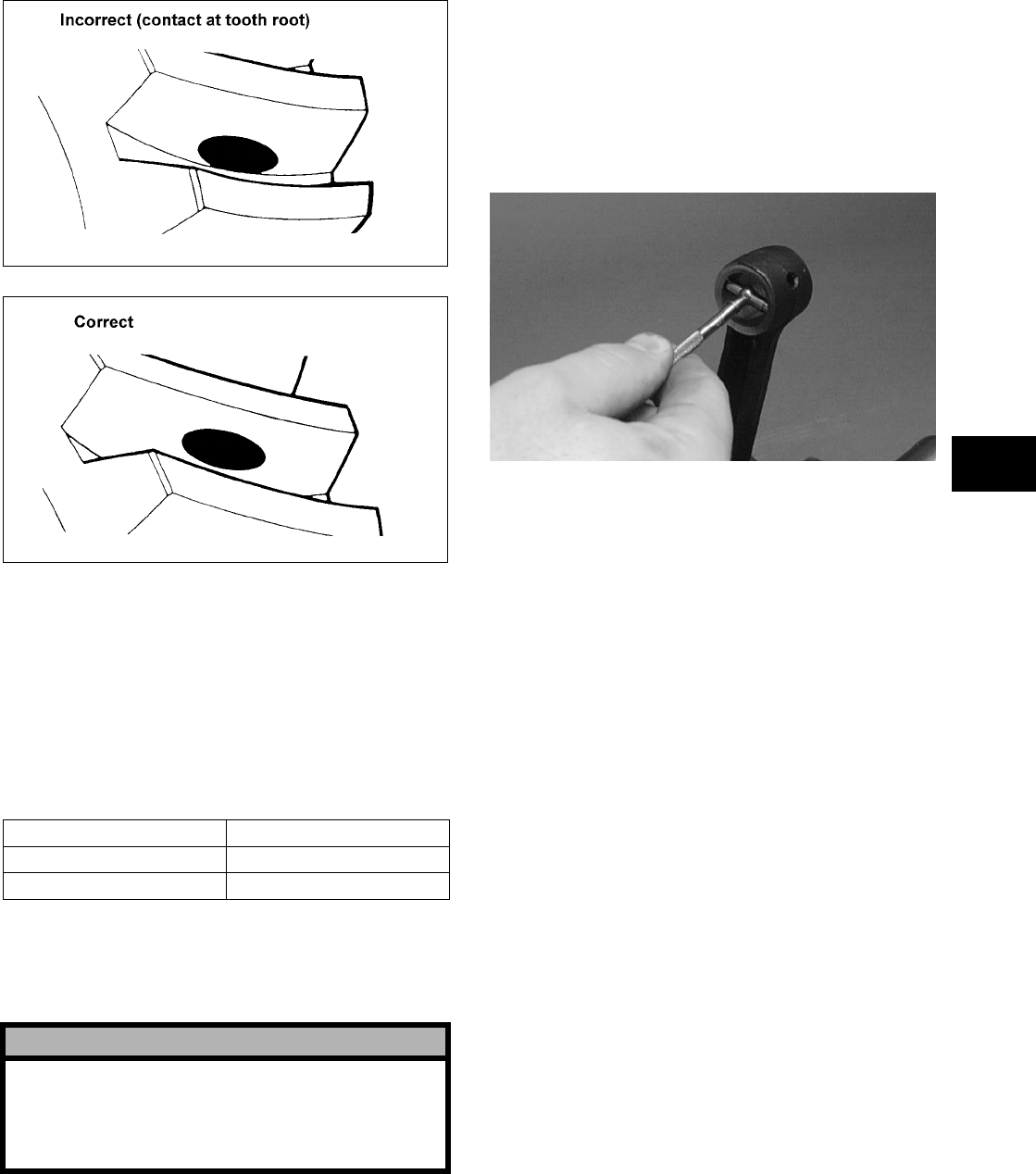
3-37
3
ATV-0105
ATV-0104
Correcting Tooth Contact
NOTE: If tooth contact pattern is comparable to
the correct pattern illustration, no correction is
necessary.
1. If tooth contact pattern is comparable to an
incorrect pattern, correct tooth contact according
to the following chart.
NOTE: To correct tooth contact, steps 1 and 2
(with NOTE) of “Correcting Backlash” must be fol-
lowed and the above “Tooth Contact/Shim Correc-
tion” chart must be consulted.
CRANKSHAFT ASSEMBLY
Measuring Connecting Rod
(Small End Inside Diameter)
1. Insert a snap gauge into the upper connecting
rod small end bore; then remove the gauge and
measure it with micrometer.
CC290D
2. Maximum diameter must not exceed specifica-
tions.
Measuring Connecting Rod
(Small End Deflection)
1. Place the crankshaft on a set of V-blocks and
mount a dial indicator and base on the surface
plate. Position the indicator contact point against
the center of the connecting rod small end jour—
nal.
2. Zero the indicator and push the small end of the
connecting rod away from the dial indicator.
3. Maximum deflection must not exceed specifica-
tions.
Measuring Connecting Rod
(Big End Side-to-Side)
1. Push the lower end of the connecting rod to one
side of the crankshaft journal.
2. Using a feeler gauge, measure the gap between
the connecting rod and crankshaft journal.
Tooth Contact Shim Correction
Contacts at Top Decrease Shim Thickness
Contacts at Root Increase Shim Thickness
! CAUTION
After correcting tooth contact, backlash must again
be checked and corrected (if necessary). Continue
the correcting backlash/correcting tooth contact
procedures until they are both within tolerance val-
ues.
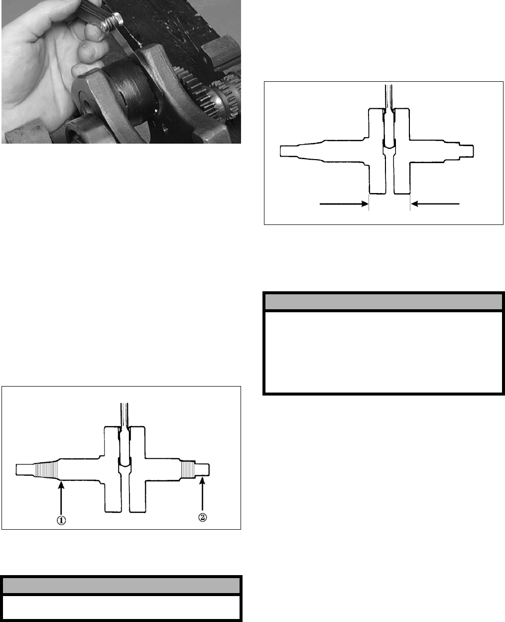
3-38
CC289D
3. Acceptable gap range must be within specifica-
tions.
Measuring Connecting Rod
(Big End Width)
1. Using a calipers, measure the width of the
connecting rod at the big-end bearing.
2. Acceptable width range must be within specifi-
cations.
Measuring Crankshaft (Runout)
1. Place the crankshaft on a set of V blocks.
2. Mount a dial indicator and base on the surface
plate. Position the indicator contact at point 1 of
the crankshaft.
ATV-1074
3. Zero the indicator and rotate the crankshaft
slowly.
4. Maximum runout must not exceed specifica-
tions.
NOTE: Proceed to check runout on the other end
of the crankshaft by positioning the indicator con-
tact at point 2 and following steps 2-4.
Measuring Crankshaft
(Web-to-Web)
1. Using a calipers, measure the distance from the
outside edge of one web to the outside edge of
the other web.
ATV-1017
2. Acceptable width range must be within specifi-
cations.
COUNTERSHAFT
Disassembling
1. Remove drive gear #2; then remove the circlip
securing the reverse gear dog.
2. Remove the reverse gear dog; then remove the
circlip securing the reverse driven gear.
3. Remove the reverse driven gear and account for
the washer, bushing, and bearing.
4. Remove the low driven gear washer and lock
washers; then remove the low driven gear.
Account for the bushing and bearing.
5. Remove the washer; then remove the sliding
dog.
6. Remove the high driven gear. Account for the
washer, bushing, and bearing.
! CAUTION
Care should be taken to support the connecting rod
when rotating the crankshaft.
! CAUTION
When disassembling the countershaft, care must
be taken to note the direction each major compo-
nent (dog, gear) faces. If a major component is
installed facing the wrong direction, transmission
damage may occur and/or the transmission will
malfunction. In either case, complete disassembly
and assembly will be required.
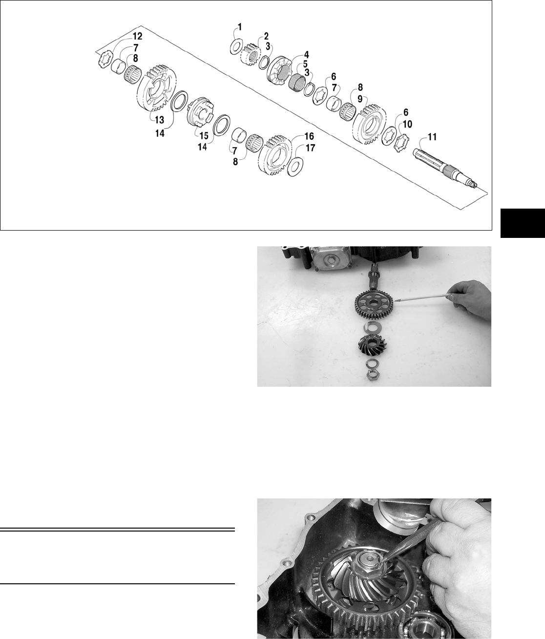
3-39
3
Assembling
738-929A
1. Place the high driven gear onto the countershaft
making sure the bearing, bushing, and washer
are properly positioned.
2. Place the sliding dog onto the countershaft.
3. Place the low driven gear onto the countershaft
making sure the bearing and bushing are prop-
erly positioned; then place the lock washers and
washer onto the shaft.
4. Place the reverse driven gear onto the counter-
shaft making sure the bearing, bushing, and
washer are properly positioned; then secure with
the circlip.
5. Place the reverse gear dog onto the countershaft;
then secure with the circlip.
6. Place drive gear #2 onto the countershaft.
NOTE: When installing the countershaft assem-
bly, account for the washer on each end of the
shaft.
Assembling Crankcase
Half
1. Install the output shaft assembly into the crank-
case making sure the two gears, shim, washer,
and nut are properly sequenced.
CC686
NOTE: The beveled side of the secondary drive
gear must face upward.
2. Apply red Loctite #271 to the threads of the out-
put shaft; then secure with the nut. Tighten nut
to specifications; then using a punch, peen the
nut.
CC687
KEY
1. Washer — Drive Gear (R)
2. Drive Gear #2
3. Circlip
4. Reverse Gear Dog
5. Spacer
6. Washer
7. Bushing
8. Bearing
9. Reverse Driven Gear
10. Lock Washer
11. Countershaft
12. Lock Washer
13. Low Driven Gear
14. Driven Gear Washer
15. Sliding Dog
16. High Driven Gear
17. Washer — Drive Gear (L)
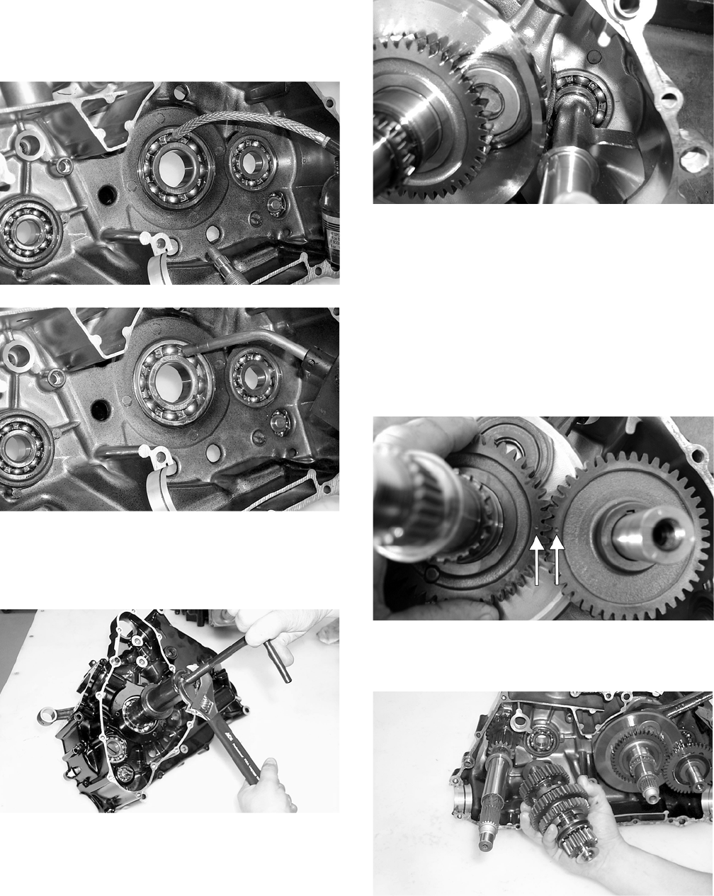
3-40
3. Apply a liberal amount of engine oil to the
crankshaft bearing. Using a propane torch, heat
the bearing until the oil begins to smoke; then
slide the crankshaft assembly into place.
CC688
CC689
NOTE: If heating the bearing is not possible, the
crankshaft can be installed using a crankshaft
installing tool.
CC690
4. Install the crank balancer.
CD832
NOTE: It will be necessary to rotate the crank
balancer until the counterweight is facing away
from the crankshaft; then rotate the crankshaft
clockwise into the journal area to allow the crank
balancer to be fully seated.
5. Place the key into the crank balancer keyway;
then install the crank balancer gear making sure
the alignment dots on the crank balancer gear
and the crankshaft gear align.
CD826A
6. Place a washer on each end of the countershaft
assembly; then install the assembly.
CC674
7. Install the driveshaft.
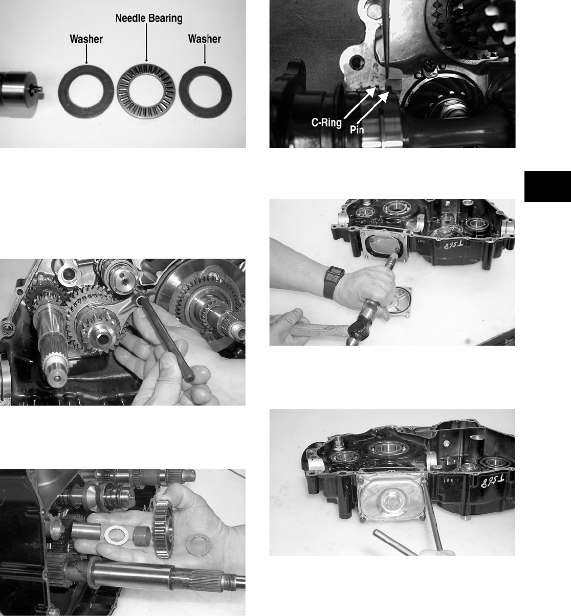
3-41
3
8. Install the thrust bearing assembly (flat washer,
needle bearing, flat washer) on the shift shaft;
then install the shaft assembly making sure the
two holes on the end of the shaft are positioned
vertically.
PR382A
9. Insert the two shift forks into the sliding dogs
noting the direction of the tabs from disassem-
bling; then install the shift fork shaft.
NOTE: Make sure the shift fork tabs face upward
and that they are properly seated into the shift
cams.
CC669
10. Install the reverse idler gear assembly noting the
positioning of the two washers, gear, bushing,
and shaft.
CC668
11. Install the front and rear secondary driven shaft
assemblies into the right side of the crankcase
making sure the bearing locating pins are facing
upward and the bearing C-ring is fully seated in
the crankcase.
CD268A
12. Place the oil strainer into position; then secure
with the two machine screws.
CC682
13. Place the oil strainer cap into position making
sure the O-ring is in position; then secure the
cap with machine screws. Tighten securely.
CC681
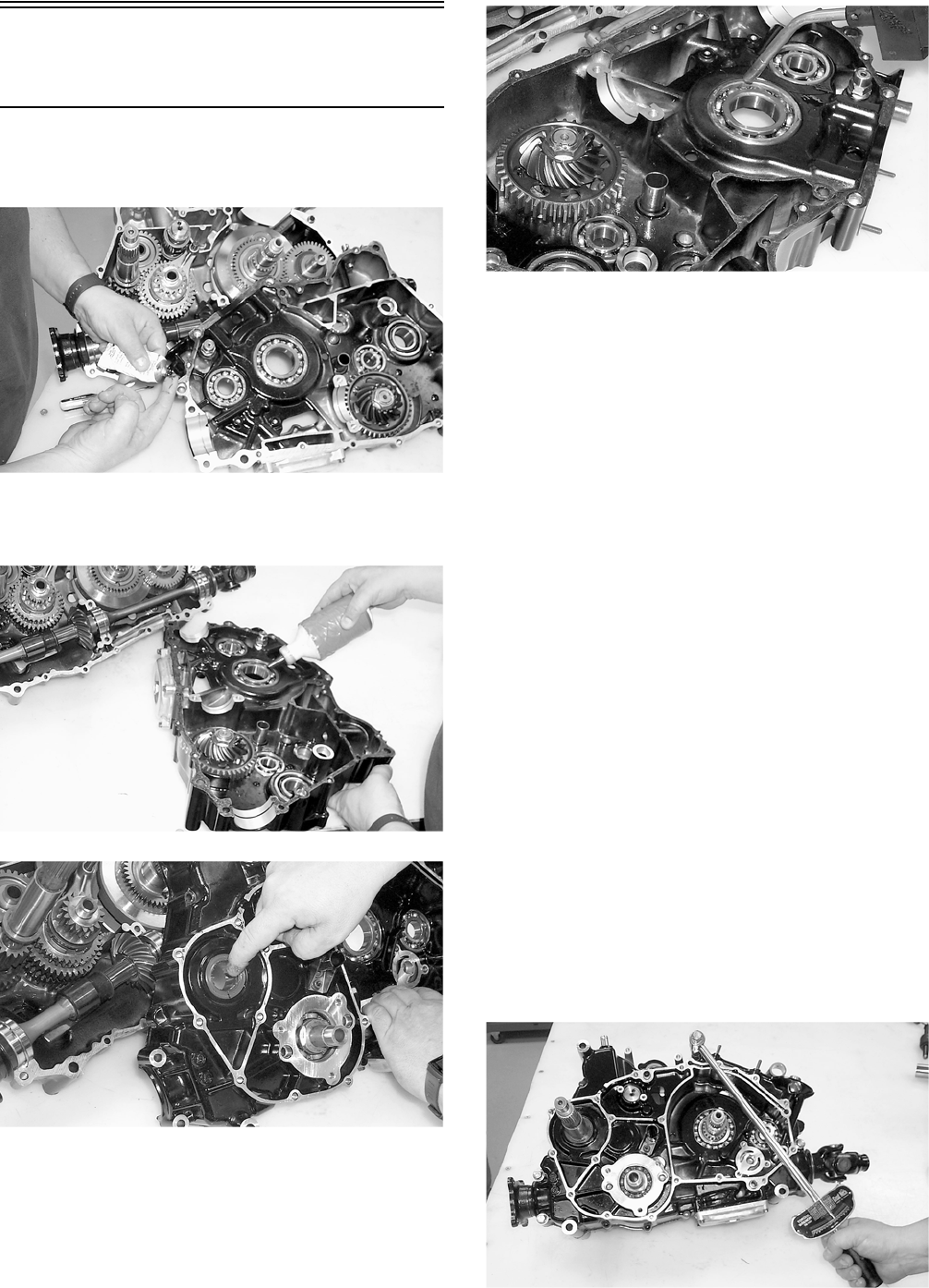
3-42
Joining Crankcase
Halves
1. Apply High-Temp Sealant (p/n 0636-069) to the
left-side mating surface.
CC693
2. Lightly oil all bearings and grease all shafts in
the left-side crankcase.
CC694
CC696
3. Using a propane torch, heat the left-side crank-
shaft bearing until the oil begins to smoke; then
join the two crankcase halves.
CC695
4. Using a plastic mallet, lightly tap the case halves
together until machine screws can be installed.
5. From the left side, install the 8 mm cap screws;
then tighten only until snug.
NOTE: Rotate the shafts back and forth to
ensure no binding or sticking occurs.
6. From the right side, install the remaining 8 mm
machine screws (one inside the case); then
tighten only until snug.
NOTE: Rotate the shafts back and forth to
ensure no binding or sticking occurs.
7. From the right side, install the eight case half 6
mm machine screws; then tighten only until
snug.
NOTE: Rotate the shafts back and forth to
ensure no binding or sticking occurs.
8. From the left side, install the 6 mm machine
screws; then tighten only until snug.
NOTE: Rotate the shafts back and forth to
ensure no binding or sticking occurs.
9. In a crisscross/case-to-case pattern, tighten the 8
mm machine screws (from steps 5-6) until the
halves are correctly joined; then tighten to spec-
ifications.
CC697
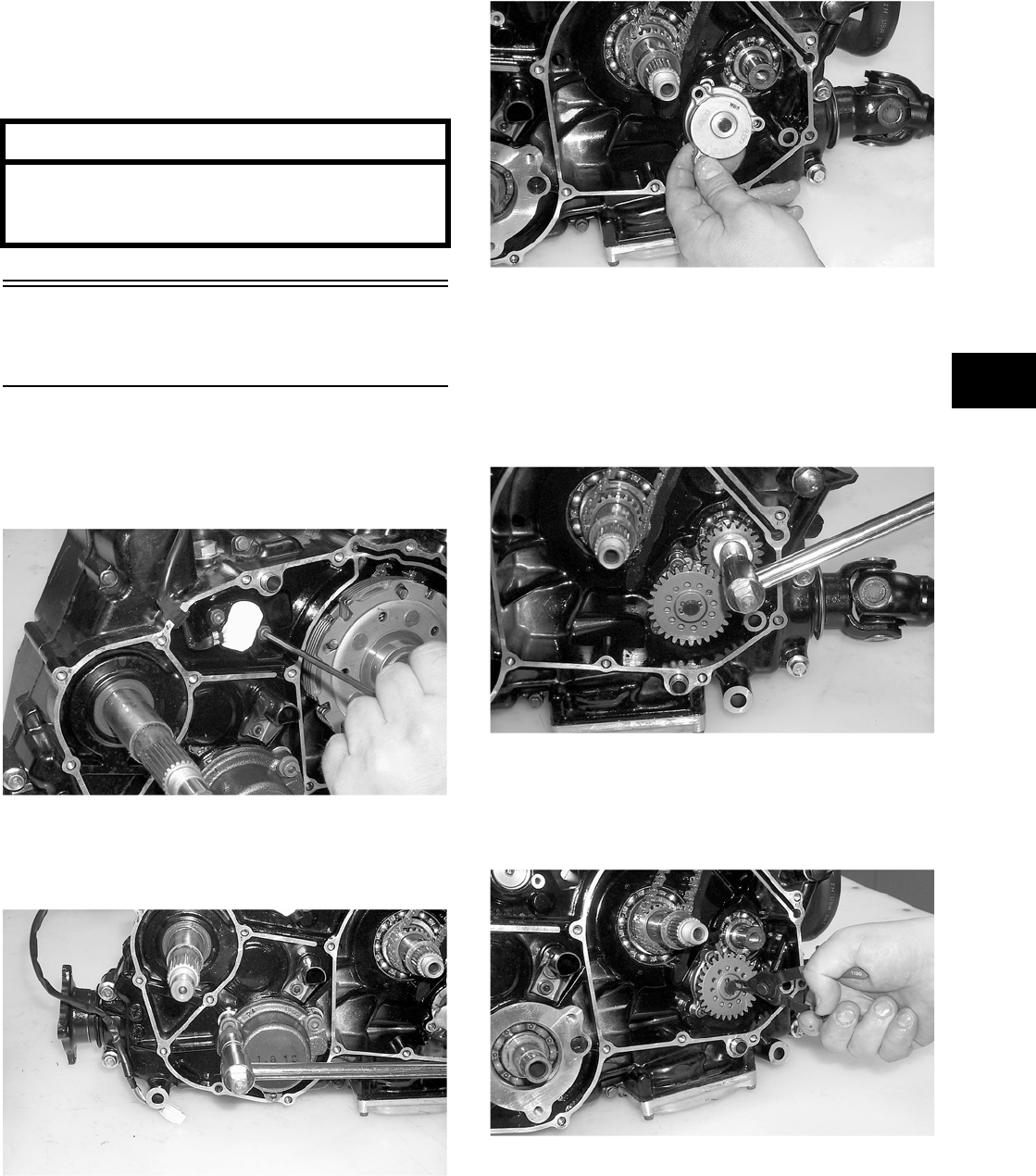
3-43
3
NOTE: Rotate the shafts back and forth to
ensure no binding or sticking occurs.
10. In a crisscross/case-to-case pattern, tighten the 6
mm machine screws (from steps 7-8) to specifi-
cations.
NOTE: Rotate the shafts back and forth to
ensure no binding or sticking occurs.
Installing Left-Side
Components
1. Install the shift indicator sending unit making
sure the two neutral contact pins and the two
springs are properly positioned. Tighten the
machine screws securely.
CC602
2. Install the secondary shaft bearing housing mak-
ing sure the two alignment pins are properly
positioned. Tighten the cap screws securely.
CC711
3. Install the timing chain on the crankshaft; then
install the oil pump onto the engine. Tighten the
machine screws securely.
CC613
4. Install the oil pump drive gear spacer onto the
crank balancer shaft. Grease the pin and insert it
into the shaft; then install the drive gear making
sure the raised side of the gear is facing toward
the inside. Secure the gear with the cap screw
(threads coated with red Loctite #271) and the
washer. Tighten the cap screw to specifications.
CC712
5. Grease the driven gear pin and insert it into the
oil pump shaft; then install the driven gear (not-
ing the direction of the sides of the gear from
removing). Secure with a snap ring.
CC609
NOTE: When installed correctly, the sides of the
drive and driven gears will be flush with each
other.
AT THIS POINT
After completing center crankcase components,
proceed to Installing Right-Side Components, to
Installing Left-Side Components, and to In—
stalling Top-Side Components.
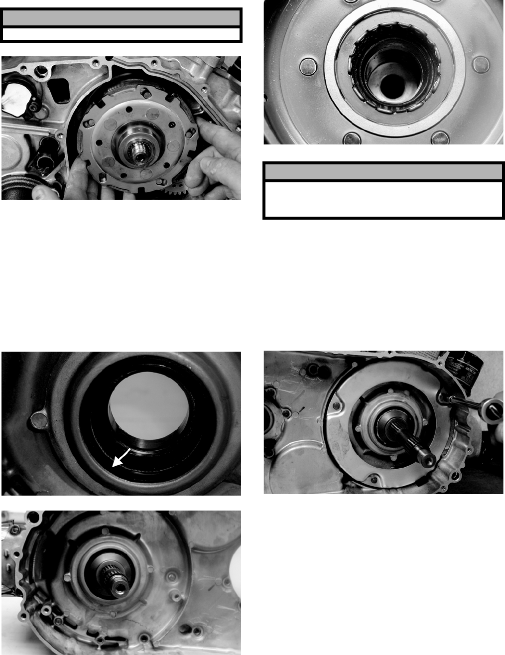
3-44
6. Install the clutch shoe assembly and secure with
the nut (threads coated with red Loctite #271).
Tighten to specifications.
CD979
7. Apply grease to the outer edges of the clutch
housing; then from inside the clutch cover,
install the clutch housing into the cover using a
rubber mallet.
8. Install the clutch cover alignment pins into the
crankcase, apply oil to the cover gasket, and
install the gasket onto the crankcase.
9. Lightly grease the clutch housing seal; then
insert the left fixed drive spacer.
CF088A
CF086
10. Install the one-way clutch into the clutch hous-
ing assembly.
CF084
11. Place the clutch cover/clutch housing assembly
into position on the crankcase; then secure with
the machine screws making sure the differ-
ent-lengthed machine screws are in their proper
location. Tighten to specifications.
12. Place the air intake plate into position; then
tighten the machine screws (threads treated with
a small amount of red Loctite #271) securely.
CD970
13. Place the driven pulley assembly into position
and secure with the nut. Tighten to specifica-
tions.
! CAUTION
Note that the nut has left-hand threads.
! CAUTION
When installed correctly, the green alignment dot
(or the word OUTSIDE) on the one-way clutch DOES
NOT SHOW.
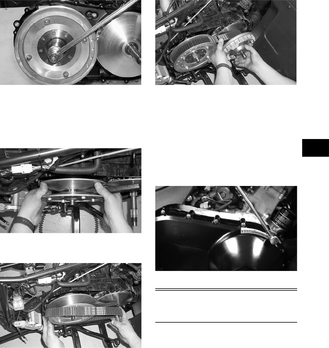
3-45
3
CC726
14. Slide the fixed drive face onto the shaft.
15. Spread the faces of the driven pulley by pushing
the inner face toward the engine while turning it
counterclockwise; then when the faces are sepa-
rated, insert a wedge (approximately 3/8 in.
thick) between the faces. Release the inner face.
CC549
16. Place the V-belt into position on the driven pul-
ley and over the front shaft.
CC550
NOTE: The arrows on the V-belt should point for-
ward.
17. Pinch the V-belt together near its center and
slide the spacer and movable drive face onto the
shaft. Secure the drive face with a nut (threads
coated with red Loctite #271). Tighten the nut to
specifications.
CC552
NOTE: At this point, the wedge can be removed
from between the driven pulley faces.
18. Rotate the V-belt and drive/driven assemblies
until the V-belt is flush with the top of the driven
pulley.
19. Place the V-belt cover gasket into position; then
install the cover and secure with the machine
screws making sure the different-lengthed
machine screws are in their proper location.
Tighten the machine screws to specifications.
CD083
Installing Right-Side
Components
NOTE: Plug the oil passage in the crankcase
housing prior to installing the drive gear/driven
gear assembly to prevent loss of an alignment pin.
1. Install the water pump drive gear alignment pin
and the drive gear (with the flat side of the gear
facing outward as noted in removing); then
secure with the snap ring.
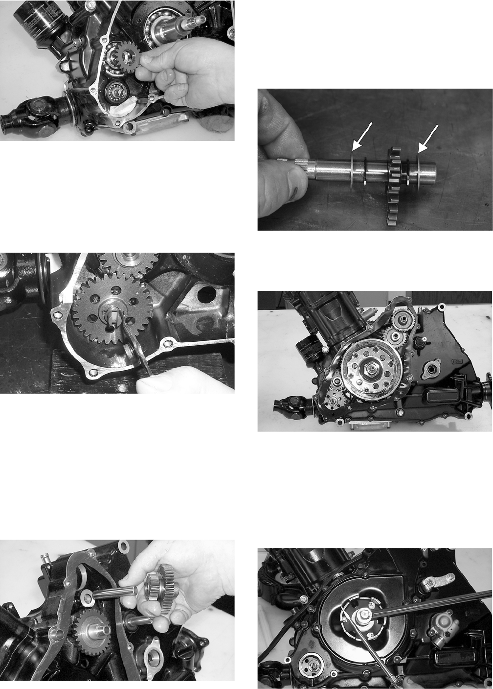
3-46
CC641
NOTE: The sharp side of the snap ring should be
facing outward.
2. Install the water pump driven gear alignment pin
and the driven gear (with the beveled side of the
gear facing outward as noted in removing); then
secure with the snap ring.
CC845
NOTE: The sharp side of the snap ring should be
facing outward.
NOTE: Once the gears are secured, remove the
oil passage plug from the crankcase.
3. Install the two starter gear shafts; then install the
two starter gears (with the beveled side of the
intermediate gear facing inward as noted in
removing).
CC636
4. In order on the crankshaft, install a washer, ring
gear, key, and the magneto rotor. Secure with the
nut (threads coated with red Loctite #271).
Tighten to specifications.
5. Install the shift shaft with the two washers mak-
ing sure the washers are properly positioned.
CD954A
6. Lubricate the magneto cover gasket with fresh
engine oil; then place it into position on the two
dowel pins.
CC629
7. Lubricate the two magneto cover oil seals; then
install the magneto cover and secure with the
cap screws. Tighten only until snug.
8. Place the starter cup into position on the crank-
shaft making sure a new, lubricated O-ring is
inside the cup. Tighten the flange nut to specifi-
cations.
CC710
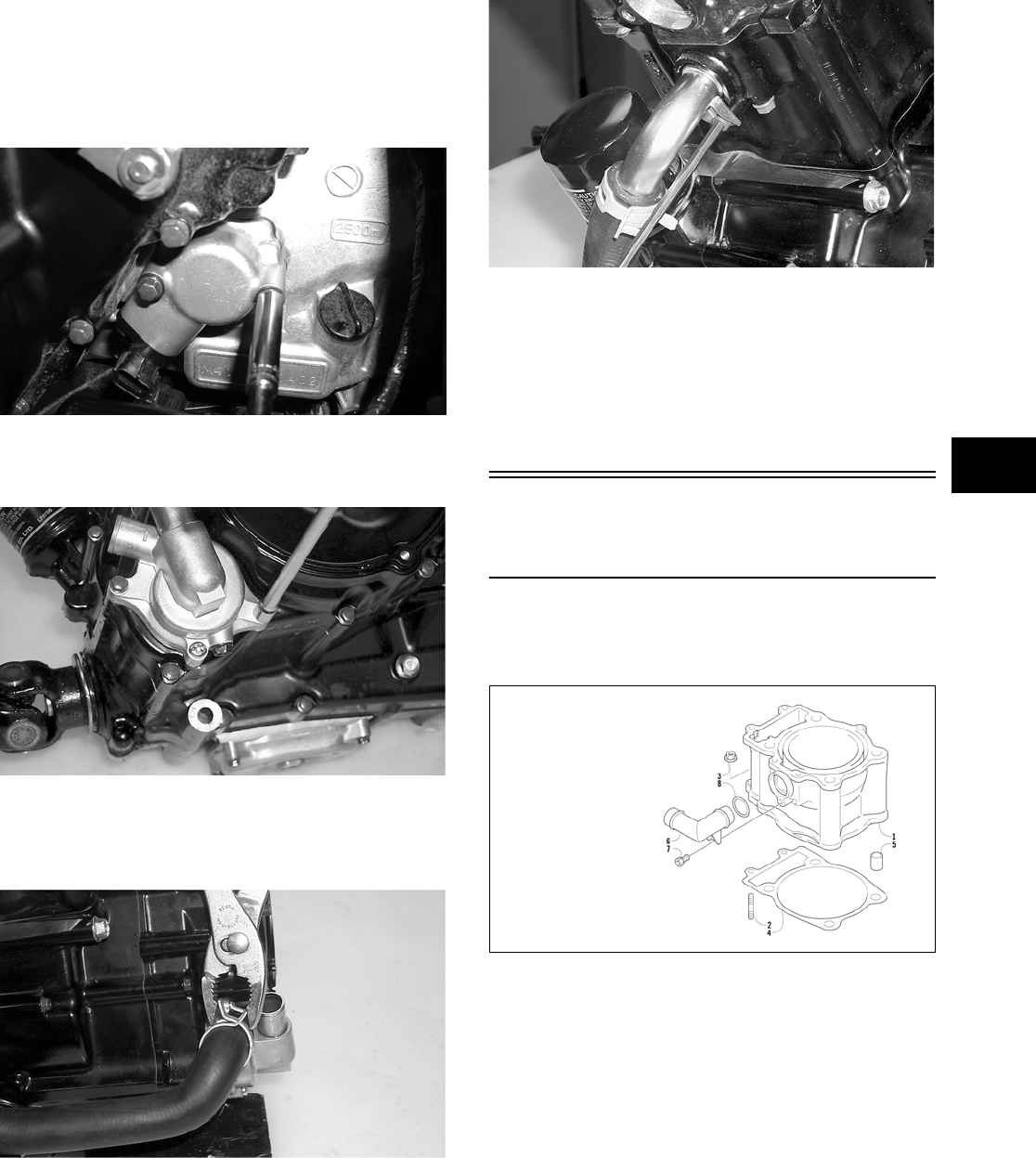
3-47
3
9. Tighten the cap screws (from step 6) to specifi-
cations.
10. Place the speed sensor housing and gasket into
position and secure with the two cap screws.
Tighten securely.
CD069
11. Place the water pump into position and secure
with two machine screws. Tighten securely.
CC623
12. Install the crossover tube on the water pump and
cylinder head making sure the O-ring is properly
positioned.
CC619
CC620
13. Install the shift arm on the shift arm shaft mak-
ing sure the scribed marks (from removing) are
aligned. Tighten securely.
14. Place the recoil starter assembly into position on
the left-side cover; then tighten four machine
screws to specifications.
Installing Top-Side
Components
A. Piston
B. Cylinder
0732-301
NOTE: If the piston rings were removed, install
them in this sequence.
A. Install ring expander (4) in the bottom groove
of the piston; then install the thin oil rings (3)
over the expander making sure the expander
ends do not overlap. Stagger the end gaps of
the upper and lower thin oil rings according
to the illustration.
KEY
1. Cylinder
2. Stud Bolt
3. Nut
4. Cylinder Gasket
5. Pin
6. Water Hose Union
7. Cap Screw
8. O-Ring
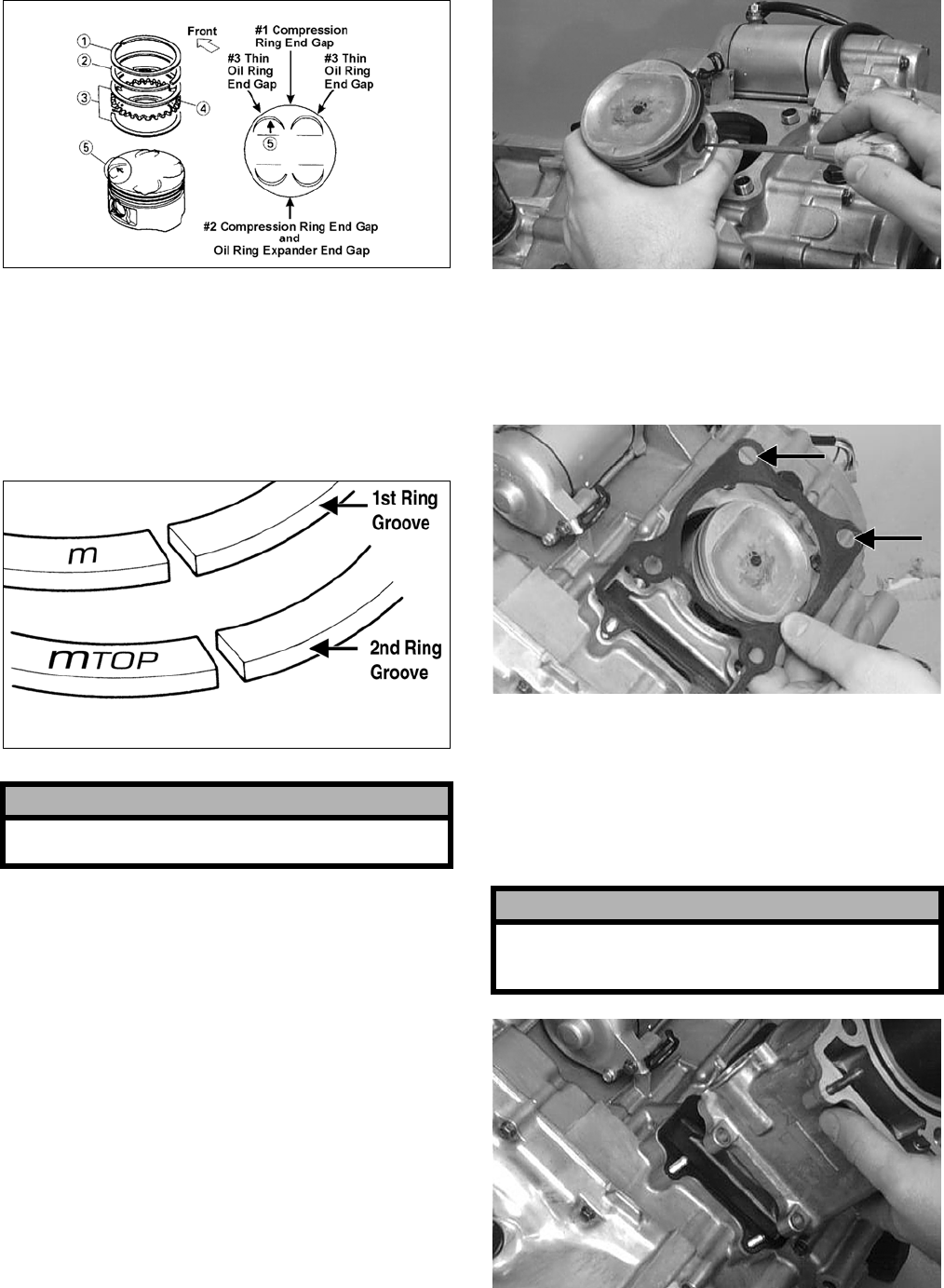
3-48
ATV-1085B
NOTE: Note the direction of the exhaust side of
the piston (5) for correct ring end gap orientation.
B. Install the compression ring with the orienta-
tion mark (MTOP) in the 2nd (middle) ring
groove and the ring with the orientation mark
(M) in the 1st (top) ring groove.
ATV-1024A
1. Install the piston on the connecting rod making
sure there is a circlip on each side and the open
end of the circlip faces upwards.
NOTE: The piston should be installed so the
arrow points toward the exhaust.
CC032D
2. Place the two alignment pins into position. Place
the cylinder gasket into position; then place a
piston holder (or suitable substitute) beneath the
piston skirt and square the piston in respect to
the crankcase.
CC025D
3. Lubricate the inside wall of the cylinder; then
using a ring compressor or the fingers, compress
the rings and slide the cylinder over the piston.
Route the cam chain up through the cylinder
cam chain housing; then remove the piston
holder and seat the cylinder firmly on the crank-
case.
CC024D
! CAUTION
Incorrect installation of the piston rings will result
in engine damage.
! CAUTION
The cylinder should slide on easily. Do not force the
cylinder or damage to the piston, rings, cylinder, or
crankshaft assembly may occur.
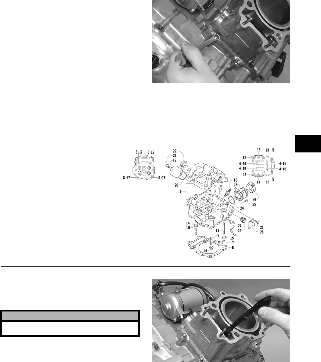
3-49
3
4. Loosely install the two nuts which secure the
cylinder to the crankcase.
NOTE: The two cylinder-to-crankcase nuts will
be tightened in step 10.
CC023D
5. Install the coolant hose onto the crankcase union
and tighten the clamp.
C. Cylinder Head
D. Valve Cover
0741-101
NOTE: Steps 1-5 in the preceding sub-section
must precede this procedure.
6. Place the chain guide into the cylinder.
CC022D
7. Place the head gasket into position on the cylin-
der. Place the alignment pins into position; then
place the head assembly into position on the cyl-
inder.
KEY
1. Cylinder Head Assy
2. Valve Guide
3. Sleeve
4. Cap Screw
5. Cap Screw
6. Cylinder Head Gasket
7. Pin
8. Cap Screw
9. Stud Bolt
10. Stud Bolt
11. Stud Bolt
12. Cap Screw
13. Cap Screw
14. Nut
15. Nut
16. Gasket
17. Crush Washer
18. Spark Plug
19. Inspection Cap
20. O-Ring
21. Cap Screw
22. Cylinder Head Plug
23. Intake Pipe Assy
24. O-Ring
25. Machine Screw
26. Clamp
27. Temperature Switch
Assy
28. Thermostat Cover
29. Thermostat
! CAUTION
Care should be taken that the bottom of the chain
guide is secured in the crankcase boss.
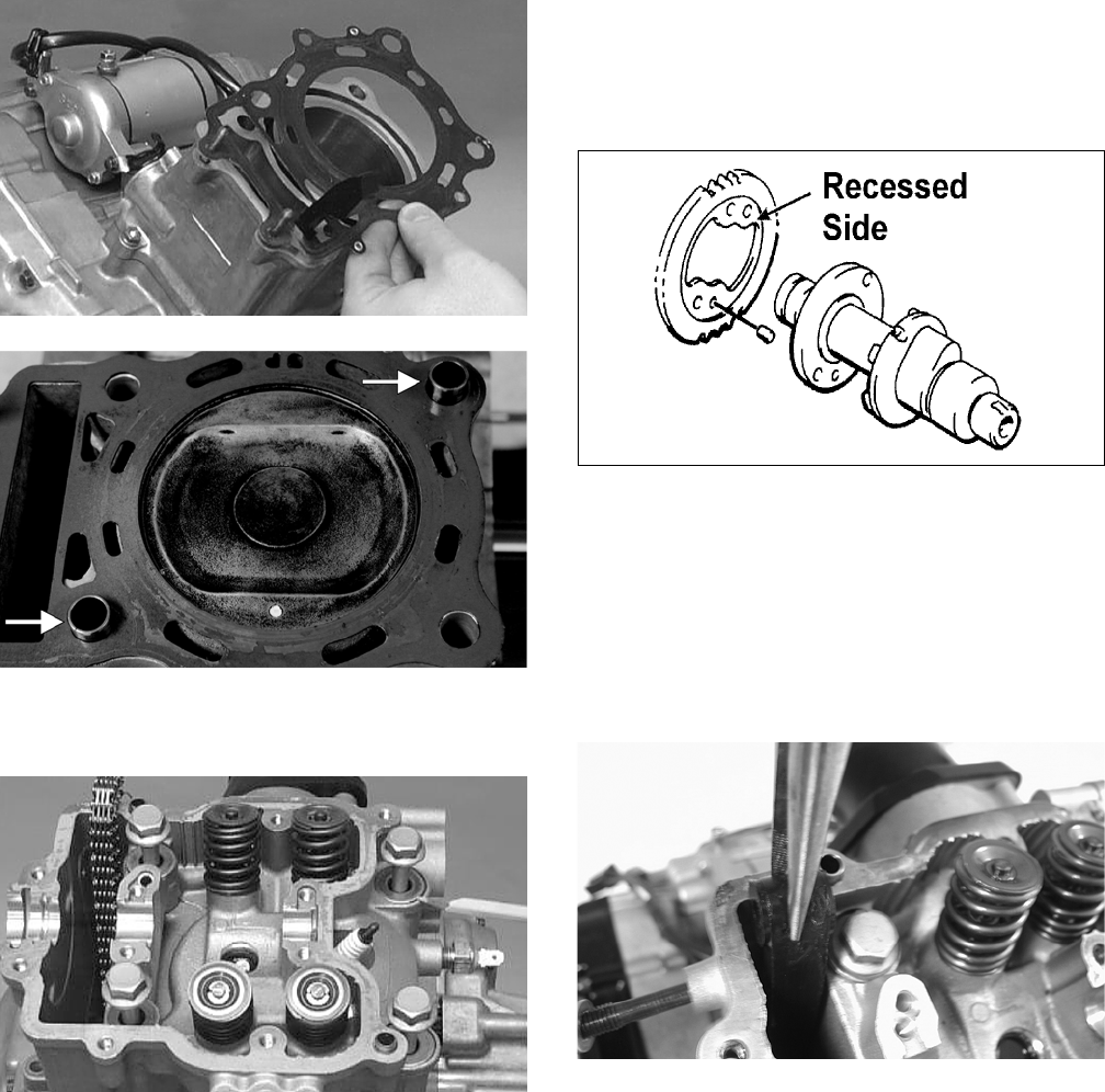
3-50
CC020D
CF057A
8. Install the four cylinder head cap screws with
copper washers. Tighten only until snug.
CC272D
9. Loosely install the five cylinder head nuts.
10. In a crisscross pattern, tighten the four cylinder
head cap screws (from step  to 5.5 kg-m (40
ft-lb); then tighten the 8 mm nut (from step 9) to
2.5 kg-m (18 ft-lb). Using a crisscross pattern,
tighten the 6 mm nuts (from step 9) to 1.1 kg-m
(8 ft-lb). Tighten the two cylinder-to- crankcase
nuts (from step 4) securely.
11. With the timing inspection plug removed and
the chain held tight, rotate the crankshaft until
the piston is at top-dead-center.
12. With the alignment pin installed in the camshaft,
loosely place the cam sprocket (with the
recessed side facing the cam shaft lobes) onto
the camshaft. At this point, do not “seat” the
sprocket onto the shaft.
732-307B
NOTE: At this point, oil the camshaft bearings,
cam lobes, and the three seating journals on the
cylinder.
13. While holding the cam chain sprocket to the
side, install the rear cam chain tensioner guide
into the cylinder head. Install the pivot cap
screw and washer.
CD461
14. With the cam lobes directed down (toward the
piston), maneuver the camshaft/sprocket assem-
bly through the chain and towards its seating
position; then loop the chain over the sprocket.
NOTE: Note the position of the alignment marks
on the end of the camshaft. They must be parallel
with the valve cover mating surface. If rotating the
camshaft is necessary for alignment, do not allow
the chain and sprocket to rotate and be sure the
cam lobes end up in the down position.
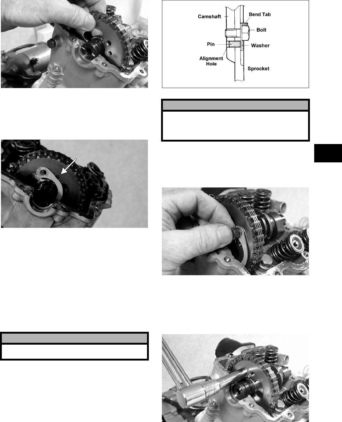
3-51
3
CD463
15. Seat the cam sprocket onto the camshaft making
sure the alignment pin in the camshaft aligns
with the smallest hole in the sprocket; then place
the camshaft/sprocket assembly onto the cylin-
der head ensuring the following.
CF013A
A. Piston still at top-dead-center.
B. Camshaft lobes directed down (toward the
piston).
C. Camshaft alignment marks parallel to the
valve cover mating surface.
D. Recessed side of the sprocket directed toward
the cam lobes.
E. Camshaft alignment pin and sprocket align-
ment hole (smallest) are aligned.
16. Place the tab-washer onto the sprocket making
sure it covers the pin in the alignment hole.
ATV1027
17. Install the first cap screw (threads coated with
red Loctite #271) securing the sprocket and
tab-washer to the camshaft. Tighten only until
snug.
CD464
18. Rotate the crankshaft until the second cap screw
securing the sprocket to the camshaft can be
installed; then install the cap screw (threads
coated with red Loctite #271) and tighten to
specifications. Bend the tab to secure the cap
screw.
CD465
! CAUTION
If any of the above factors are not as stated, go
back to step 11 and carefully proceed.
! CAUTION
Care must be taken that the tab-washer is installed
correctly to cover the alignment hole on the
sprocket. If the alignment pin falls out, severe
engine damage will result.
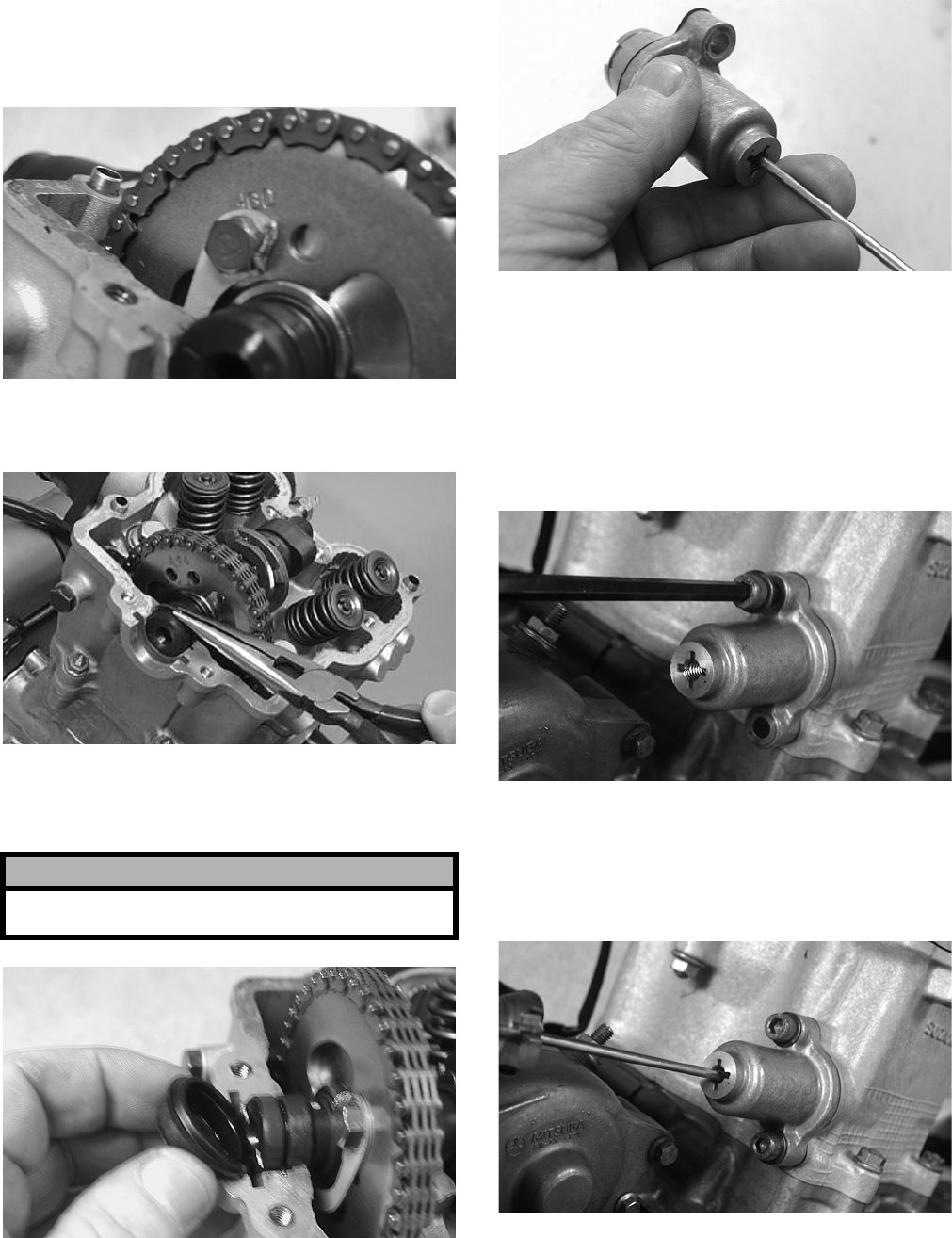
3-52
19. Rotate the crankshaft until the first cap screw
(from step 17) can be addressed; then tighten to
specifications. Bend the tab to secure the cap
screw.
CD466
20. Place the C-ring into position in its groove in the
cylinder head.
CC012D
21. Install the cylinder head plug in the cylinder
head with the open end facing downward and
toward the inside.
CD468
22. Remove the cap screw from the end of the chain
tensioner; then using a flat-blade screwdriver,
rotate the adjuster screw inside the tensioner
clockwise until the screw bottoms.
CD501
NOTE: The adjuster shaft will be drawn into the
tensioner as the adjuster screw is rotated clock-
wise. The adjuster shaft tension will be released in
step 24.
23. Place the chain tensioner adjuster assembly and
gasket into position on the cylinder and secure
with the two machine screws.
CD469
24. Using a flat-blade screwdriver, rotate the
adjuster screw inside the tensioner counter-
clockwise until all tension is released; then
install the cap screw into the end of the chain
tensioner.
CD470
! CAUTION
The open end of the plug must be positioned down-
ward.
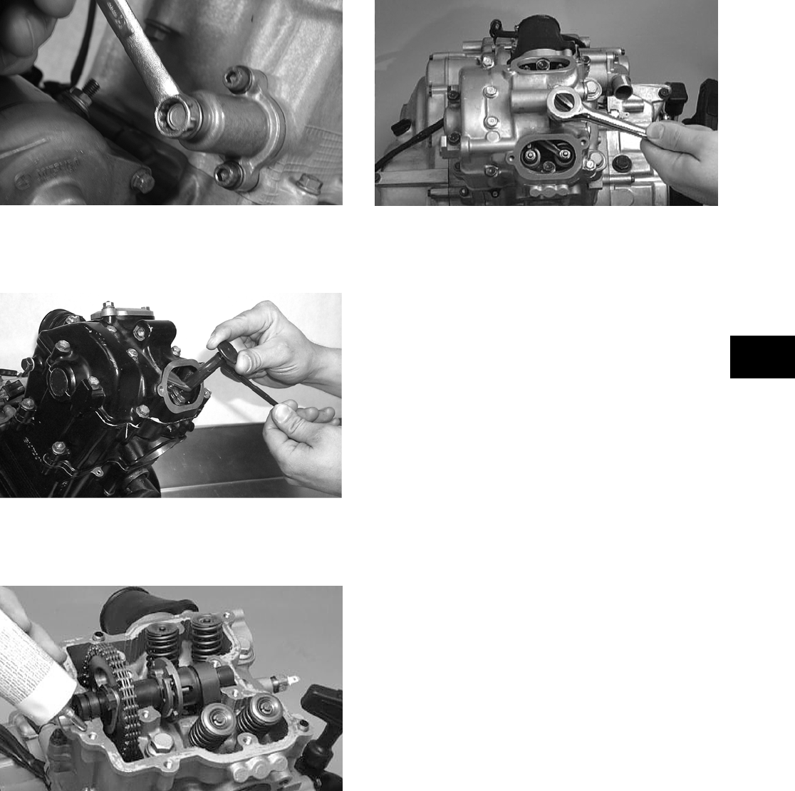
3-53
3
CD471
25. Loosen the four adjuster screw jam nuts; then
loosen the four adjuster screws on the rocker
arms in the valve cover.
CC528D
26. Apply a thin coat of Three Bond Sealant (p/n
0636-070) to the mating surfaces of the cylinder
head and valve cover.
CC275D
27. Place the valve cover into position.
NOTE: At this point, the rocker arms and
adjuster screws must not have pressure on them.
28. Install the four top side cap screws with rubber
washers; then install the remaining cap screws.
Tighten only until snug.
CC003D
29. In a crisscross pattern starting from the center
and working outward, tighten the cap screws
securely.
30. Adjust valve/tappet clearance using the follow-
ing procedure.
NOTE: Use Valve Clearance Adjuster (p/n
0444-078) for this procedure.
A. Turn the engine over until the piston reaches
top dead center on the compression stroke.
B. Place the valve adjuster onto the jam nut
securing the tappet adjuster screw; then rotate
the valve adjuster dial clockwise until the end
is seated in the tappet adjuster screw.
C. While holding the valve adjuster dial in
place, use the valve adjuster handle and
loosen the jam nut; then rotate the tappet
adjuster screw clockwise until friction is felt.
D. Align the valve adjuster handle with one of
the marks on the valve adjuster dial.
E. While holding the valve adjuster handle in
place, rotate the valve adjuster dial counter-
clockwise until specified valve/tappet clear-
ance is attained.
NOTE: Rotating the valve adjuster dial counter-
clockwise will open the valve/tappet clearance by
0.05 mm (0.002 in.) per mark.
F. While holding the adjuster dial at the proper
clearance setting, tighten the jam nut securely
with the valve adjuster handle.
31. Place the two tappet covers into position making
sure the proper cap screws are with the proper
cover. Tighten the cap screws securely.
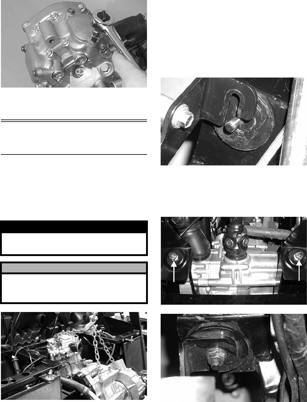
3-54
CC001D
32. If removed, install the spark plug. Tighten to
specifications.
Installing
Engine/Transmission
NOTE: Arctic Cat recommends that new gaskets
and O-rings be installed whenever servicing the
vehicle.
1. Attach suitable lifting chains to the engine/trans-
mission; then using an engine hoist, lower the
assembly into the engine compartment.
PR114
NOTE: The rear engine mounting bracket and
rear engine mounts should be attached to the
engine. The front engine mounting bracket should
be attached to the engine, and the front engine
mounts should be in the frame.
2. Align the rear engine mount studs with the holes
in the frame and slowly lower into place. The
front engine mounting bracket will then slip
over the engine mount studs.
PR146
3. Install the flange nuts on the rear engine mount
studs; then secure the front engine mounting
bracket to the front engine mount studs with two
flange nuts. Tighten the four flange nuts to
specifications.
PR153A
PR147
4. Apply multi-purpose grease to the driveshaft
splines; then align the flange marks and slide the
splines into the slip-joints.
! WARNING
Keep hands and fingers clear when lowering the
engine/transmission into place. The chains could
shift causing severe injury.
! CAUTION
Make sure that all wiring, hoses, and brake lines are
routed away from engine mounts and engine brack-
ets. Pinching or breaking of lines or shorting of
wiring could occur.
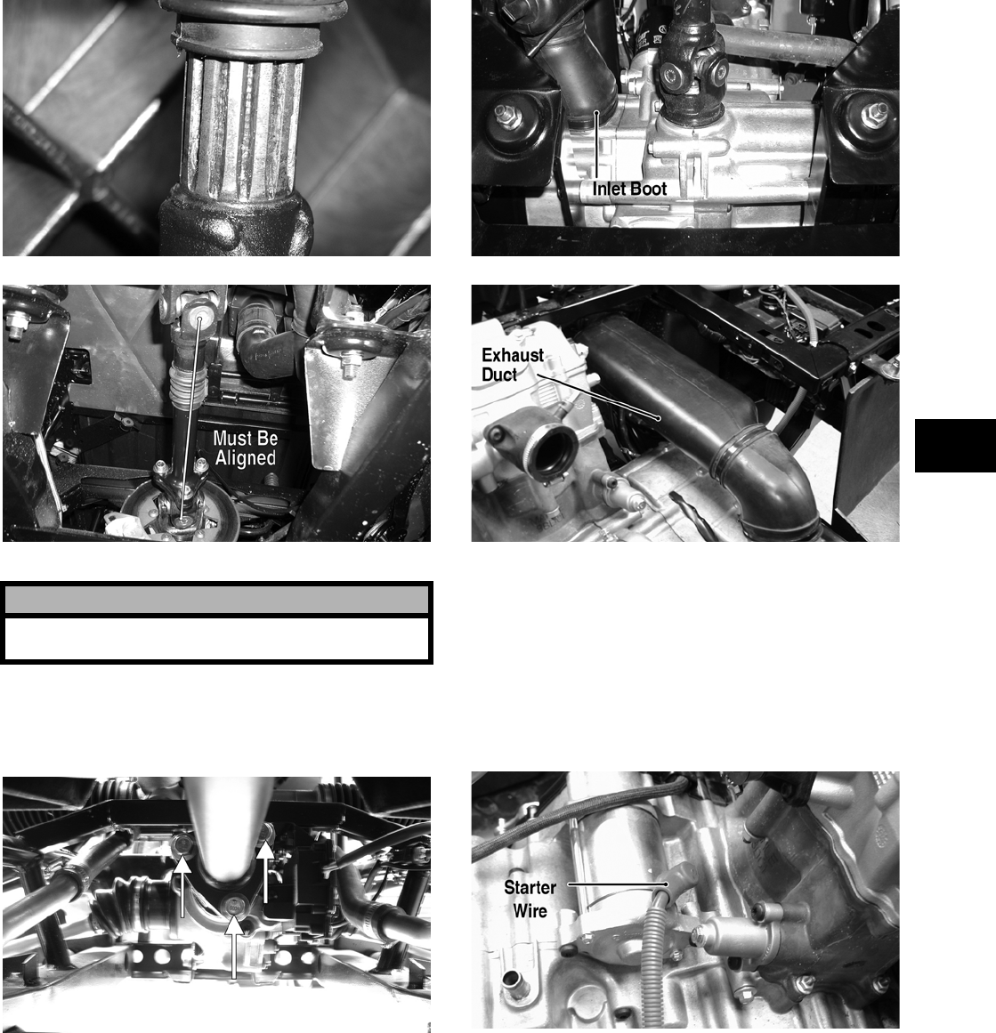
3-55
3
PR148
PR151A
5. Install the cap screws securing the drive-line
couplers to the drive flanges and tighten to spec-
ifications.
PR120A
6. Set the exhaust pipe in place; then install the
muffler and align the assembly to the engine.
Install two cap screws securing the exhaust pipe
to the cylinder head and tighten to specifica-
tions.
7. Install the inlet boot on the V-belt housing; then
install the exhaust duct connecting the outlet
housing to the V-belt housing. Tighten all
clamps securely.
PR153B
PR144B
8. Connect the lower coolant hose to the water
pump housing; then connect the upper coolant
hose to the thermostat housing. Tighten the
hose clamps securely.
9. Install the starter wire on the starter and tighten
the nut securely; then connect the CDI connec-
tor, alternator connector, shift position switch
connector, and electric choke connector.
PR145A
! CAUTION
The drive-line yokes must be aligned (timed) or
damage will occur to the universal joints and gears.
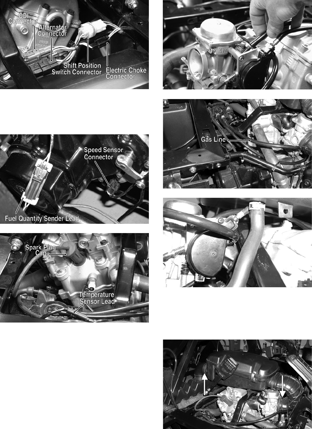
3-56
PR128A
10. From the right-side, connect the speed sensor
connector, fuel quantity sender lead, and tem-
perature sensor lead; then install the spark plug
cap.
PR155A
PR130A
11. Install the carburetor and tighten the intake boot
clamp securely; then connect the gas line, vac-
uum line, and throttle cable.
PR117
PR140B
PR154
12. Place the air filter assembly into position and
secure with the self-tapping screws; then con-
nect the intake boot to the carburetor and the
inlet housing boot to the air filter housing.
Tighten the clamps securely.
PR127A

3-57
3
13. Place the shifter assembly into position and
secure with the four machine screws. Tighten
securely.
14. Connect the shifter linkage to the shift arm plac-
ing the spacer washers in appropriate locations;
then secure with the E-clip.
NOTE: Before operating vehicle, check and
adjust shifter linkage as required (see Section 2).
15. Fill the engine/transmission with the appropriate
lubricant.
16. Fill the cooling system with the appropriate
coolant.
17. Connect the positive battery cable to the battery;
then connect the negative cable.
18. Install the left-side and right-side seat-bases;
then install the center console and seats. Make
sure the seats lock securely.
19. Start the engine and warm up to operating tem-
perature. Check for fluid leaks; then shut off
engine and check oil and coolant levels (see
Section 2).

4-1
4
SECTION 4 —
FUEL/LUBRICATION/COOLING
TABLE OF
CONTENTS
Carburetor Specifications ………………….………….….. 4-2
Carburetor Schematic …………………………….……….. 4-2
Carburetor …….………………………..…………….……….. 4-3
Cleaning and Inspecting Carburetor…………………… 4-6
Throttle Cable Free-Play …………..……………………… 4-7
Engine RPM (Idle).…………….…………….………….….. 4-7
Gas Tank ..…………….…………….…………….…………... 4-7
Gas/Vent Hoses ………………………..…………….…… 4-10
Vacuum Pulse Fuel Pump …..…………….……………. 4-10
Oil Flow Chart ……….…………….…………….…………. 4-11
Oil Filter/Oil Pump ….…………….…………….…………. 4-11
Oil Cooler .…………….…………….………….……………. 4-12
Liquid Cooling System………..…………….……………. 4-14
Radiator/Oil Cooler……………….…………….…………. 4-15
Thermostat ………………….…………….………….……… 4-17
Fan …………..………….…………….…………….…………. 4-17
Water Pump …………….……………..……………………. 4-18
Testing Vacuum Pulse Fuel Pump………………….… 4-19
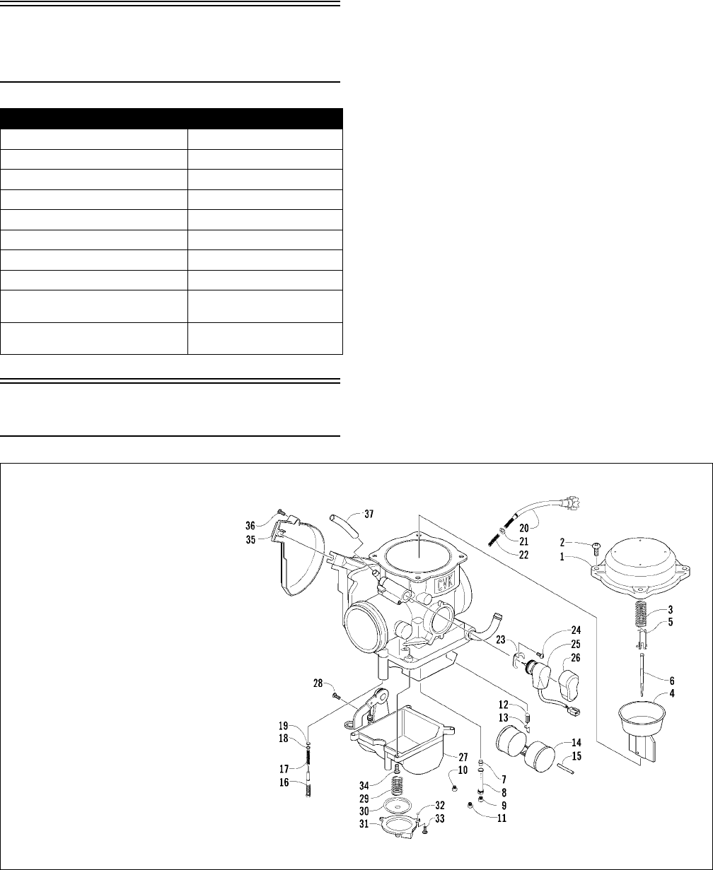
4-2
Carburetor
Specifications
Carburetor Schematic
0741-115
PROWLER XT
Ty p e Ke i h i n C V K3 6
Main Jet 132
Slow Jet 40
Pilot Screw Setting (turns) 1 1/4
Needle Jet 6.0/4.0
Jet Needle NFKS
Idle RPM 1250-1350
Starter Jet 85
Float Arm Height 17 mm
(0.7 in.)
Throttle Cable Free-Play
(at accelerator pedal)
3-6 mm
(1/8-1/4 in.)
KEY
1. Cover
2. Screw
3. Spring
4. Vacuum Piston
5. Spring Seat
6. Jet Needle
7. Needle Jet
8. Jet Holder
9. Main Jet
10. Slow Jet
11. Starter Jet
12. Float Valve
13. Clip
14. Float Set
15. Float Pin
16. Pilot Screw
17. Spring
18. Washer
19. O-Ring
20. Idle Adjust Screw
21. Washer
22. Spring
23. Plate
24. Screw
25. Electric Choke
26. Choke Cover
27. Float Chamber
Assy
28. Screw
29. Spring
30. Diaphragm Assy
31. Pump Housing
32. U-Ring
33. Screw
34. Screw
35. Cover
36. Screw
37. Vent Hose
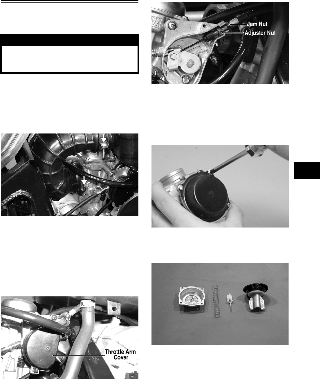
4-3
4
Carburetor
REMOVING
1. Remove the seats and center console; then
remove the left-side seat-base.
2. Loosen the clamps on the inlet boot; then
remove the boot from the left-side.
PR160A
3. Loosen the clamp securing the intake boot to the
carburetor; then separate the carburetor from the
boot.
4. Remove the gas hose and carburetor float cham-
ber vent hose.
5. Remove the throttle arm cover; then loosen the
outer jam nut on the throttle cable and discon-
nect the throttle cable from the carburetor.
PR154A
PR162A
6. Disconnect the electric choke connector; then
remove the carburetor from the vehicle.
DISASSEMBLING
1. Remove the four Phillips-head screws securing
the top cover; then remove the cover.
CH015D
2. Remove the vacuum piston assembly from the
carburetor body. Account for a spring, spring
seat, and the jet needle.
CC746
3. Remove the three screws securing the primer
housing. Account for the diaphragm assembly,
spring, and U-ring (in the housing).
! WARNING
Whenever any maintenance or inspection is per-
formed on the fuel system during which there may
be fuel leakage, there should be no welding, smok-
ing, open flames, etc., in the area.
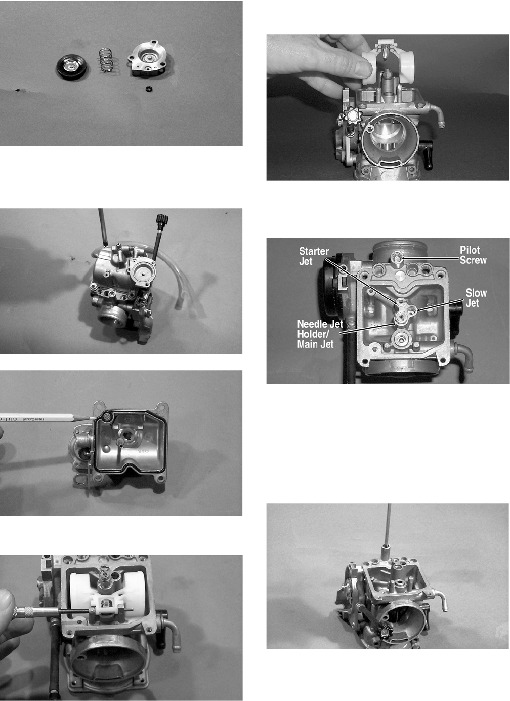
4-4
CC748
4. Remove the Phillips-head screws securing the
float chamber; then remove the chamber.
Account for the O-ring.
CC749
CC750
5. Remove the float pin.
CC752
6. Lift the float assembly from the carburetor.
Account for the float needle valve.
CC753
NOTE: Note the locations of the jets, pilot screw,
and holder for disassembling procedures.
CC761A
7. Secure the needle jet holder with a wrench; then
remove the main jet.
8. Remove the needle jet holder; then remove the
slow jet and the starter jet.
9. Remove the pilot screw. Account for a spring, a
washer, and an O-ring.
CC758
10. Unscrew and remove the idle speed adjuster
assembly. Account for the spring and washer.
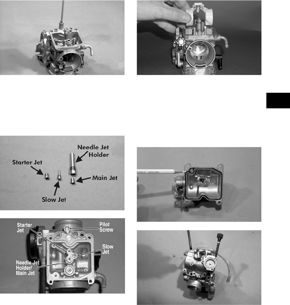
4-5
4
ASSEMBLING
1. Screw the idle speed adjuster into the carburetor
making sure the washer and spring are properly
positioned.
2. Install the pilot screw with the spring, the
washer, and the O-ring in this order.
CC758
NOTE: Turn the pilot screw clockwise until it is
lightly seated; then turn it counterclockwise the
recommended number of turns as an initial set-
ting.
NOTE: Note the locations of the jets and holder
during assembling procedures.
CC759A
CC761A
3. Install the slow jet. Tighten securely.
4. Install the main jet into the needle jet holder and
tighten securely; then install the needle jet
holder assembly into the carburetor and tighten
securely.
5. Place the float assembly (with float needle
valve) into position and secure to the carburetor
with the float pin.
CC753
NOTE: Check float arm height by placing the car-
buretor on its side w/float contacting the needle;
then measure with a caliper the height when the
float arm is in contact with the needle valve. Float
arm height should be 17 mm (0.7 in.).
6. Place the float chamber into position making
sure the O-ring is properly positioned; then
secure with the Phillips-head screws.
CC750
CC749
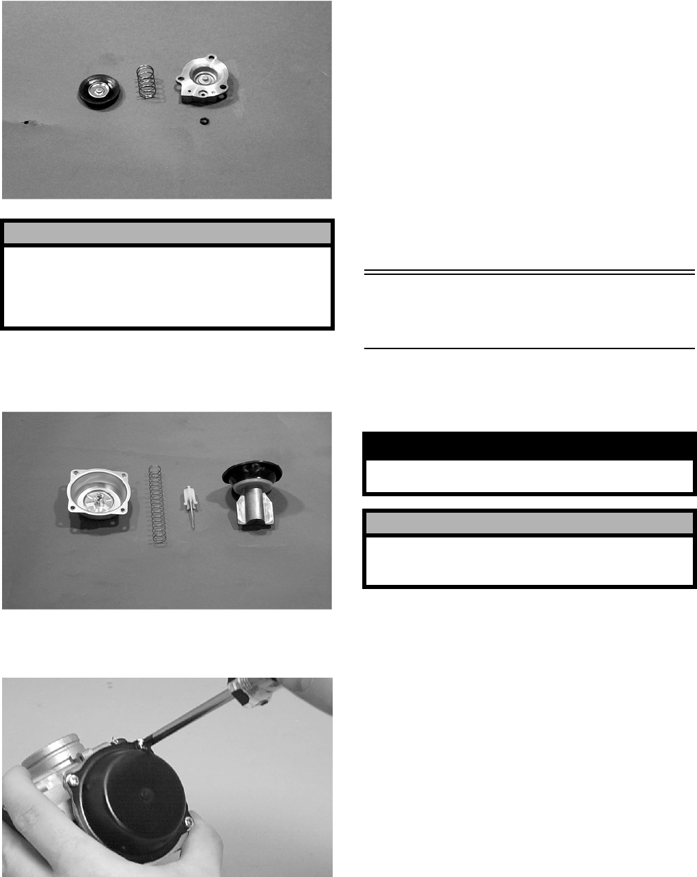
4-6
7. Place the U-ring into the primer housing. Posi-
tion the spring and diaphragm assembly (lip
toward the carburetor) onto the carburetor; then
secure the assembly with the primer housing and
three screws. Tighten securely.
CC748
8. Place the jet needle, spring seat, and spring into
the vacuum piston; then place the assembly
down into the carburetor.
CC746
9. Place the top cover into position; then secure
with the Phillips-head screws. Tighten securely.
CH015D
INSTALLING
1. Place the carburetor into position on the engine;
then connect the electric choke connector to the
main harness.
2. Connect the throttle cable to the carburetor.
Tighten the jam nut securely.
3. Connect the gas hose; then connect the carbure-
tor float chamber vent hose.
4. Place the carburetor into the intake boot and
tighten the clamp securely.
5. Install the inlet boot between the air filter hous-
ing and the carburetor; then tighten the clamps
securely.
6. Install the left-side seat-base; then install the
center console and the seats making sure the
seats lock securely.
Cleaning and Inspecting
Carburetor
NOTE: Whenever a part is worn excessively,
cracked, or damaged in any way, replacement is
necessary.
1. Place all metallic components in a wire basket
and submerge in carburetor cleaner.
2. Soak for 30 minutes; then rinse with fresh
parts-cleaning solvent.
3. Wash all non-metallic components with soap
and water. Rinse thoroughly.
4. Dry all components with compressed air only
making sure all holes, orifices, and channels are
unobstructed.
5. Inspect the carburetor body for cracks, nicks,
stripped threads, and any other imperfections in
the casting.
! CAUTION
It is important to press down on the primer housing
until it contacts the carburetor to make sure the dia-
phragm lip is properly seated in the groove in the
carburetor. If the diaphragm is not properly seated,
leakage will occur.
! WARNING
When drying components with compressed air,
always wear safety glasses.
! CAUTION
DO NOT place any non-metallic components in
parts-cleaning solvent because damage or deterio-
ration will result.
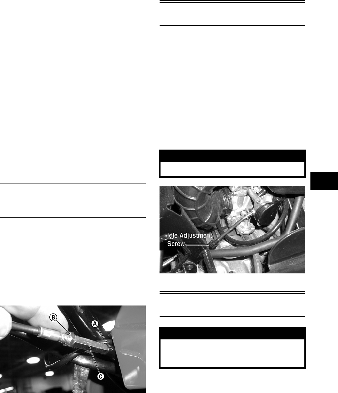
4-7
4
6. Inspect the vacuum piston/diaphragm for cracks,
imperfections in the casting, or cracks and tears
in the rubber.
7. Inspect float for damage.
8. Inspect gasket and O-rings for distortion, tears,
or noticeable damage.
9. Inspect tips of the jet needle, pilot screw, and the
inlet needle valve for wear, damage, or distor-
tion.
10. Inspect the slow jet and main jet for obstructions
or damage.
NOTE: If the slow jet is obstructed, the mixture
will be extremely lean at idle and part-throttle oper-
ation.
11. Inspect the plunger assembly/starter valve and
seat for wear or damage.
12. Inspect the carburetor mounting flange for dam-
age and tightness.
Throttle Cable
Free-Play
1. Check throttle cable free-play at the accelerator
pedal; free-play should be as specified.
2. To adjust, slide the rubber boot (A) away from
the adjuster located near the carburetor. Loosen
the jam nut (B) and rotate the adjuster (C) in the
appropriate direction until proper free-play is
attained. Tighten the jam nut against the
adjuster; then slide the rubber boot over the
adjuster.
CD560A
Engine RPM (Idle)
To properly adjust the idle RPM, a tachometer is nec-
essary.
To adjust idle RPM, use the following procedure.
NOTE: To access the idle adjustment screw, it
will be necessary to remove the seats and center
console. The idle adjustment screw is located on
the left-side of the carburetor.
1. Start the engine and warm it up to operating
temperature.
2. Rotate the idle adjustment screw clockwise or
counterclockwise until the engine idles at
1250-1350 RPM.
PR081A
Gas Tank
REMOVING
1. Remove the seats and center console; then
remove the left-side and right-side seat-bases.
2. Remove twelve cap screws and two self-tapping
screws securing the floorboard to the frame.
! WARNING
Adjust the idle to the correct RPM. Make sure the
engine is fully warm before adjusting the idle RPM.
! WARNING
Whenever any maintenance or inspection is made
on the fuel system during which there may be fuel
leakage, there should be no welding, smoking,
open flames, etc., in the area.
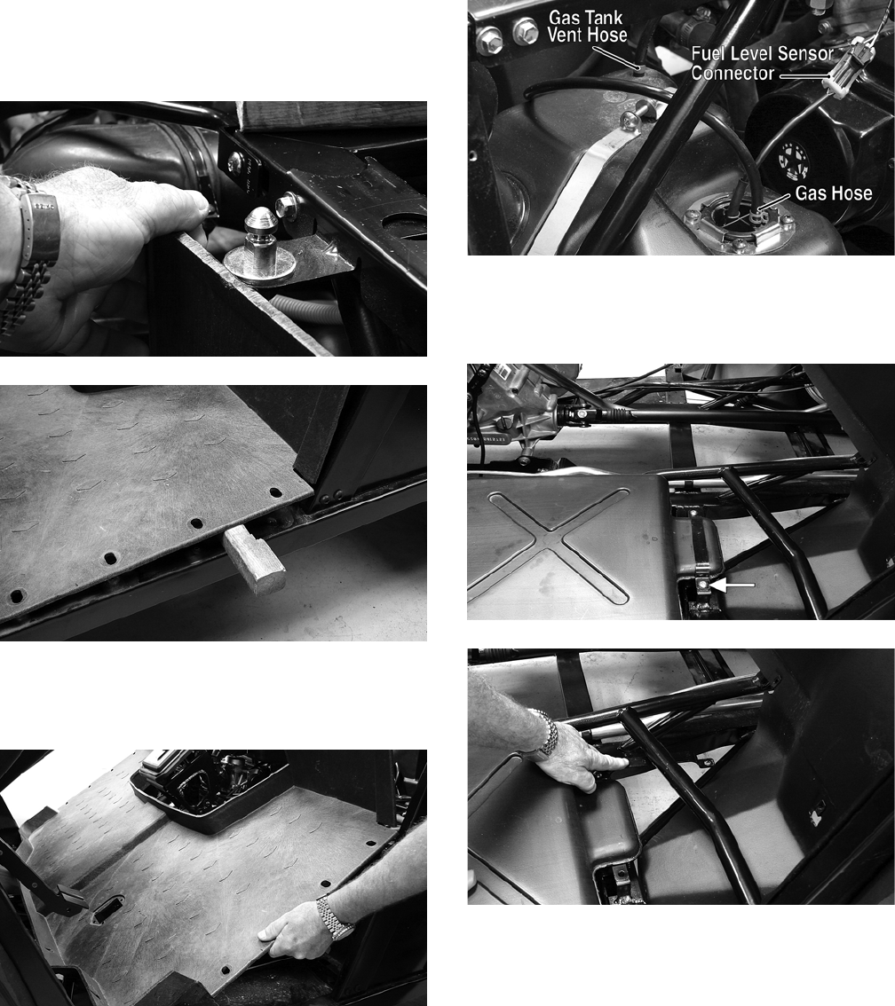
4-8
3. While pulling forward on the upper portion of
the floorboard, lift the rear panel above the seat
lock studs; then insert a small wood block to
hold in position.
PR163
PR164
4. From the opposite side of the vehicle, repeat
step 3; then lift the rear of the floorboard up and
lift the floorboard out of the vehicle.
PR165
5. Disconnect the vent hose, gas hose, and fuel
level sensor connector; then cap the vent fitting
and gas hose fitting.
PR166B
6. Remove the outer cap screw securing the front
tank hold-down; then swing the hold-down to
the left.
PR167A
PR170
7. Remove four press-nuts securing the gas cap
inset; then remove the gas cap and inset. Install
the gas cap.
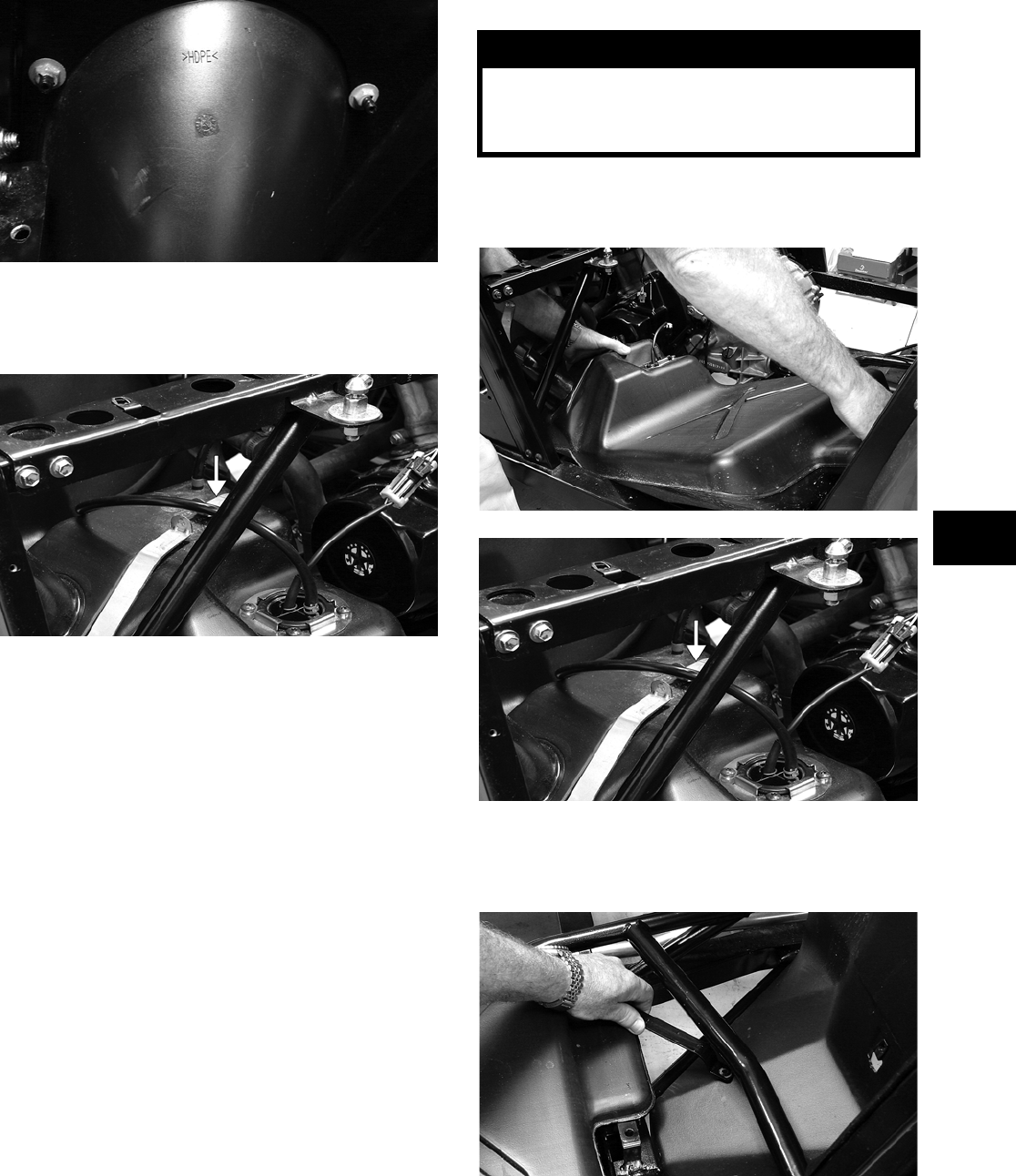
4-9
4
PR168
8. Remove the joining cap screw and nut from the
rear gas tank hold-down strap; then remove the
inside hold-down strap.
PR172A
9. Lift and slide the tank forward raising the front
of the tank first; then turn the tank and lift out
the right side.
CLEANING AND INSPECTING
NOTE: Whenever a part is worn excessively,
cracked, or damaged in any way, replacement is
necessary.
1. Clean all gas tank components with parts-clean-
ing solvent.
2. Inspect all hoses for cracks or leaks.
3. Inspect gas tank cap and tank for leaks, holes,
and damaged threads.
4. Inspect the fuel level sensor for proper opera-
tion.
INSTALLING
1. Place the gas tank into position in the vehicle;
then install the inside rear hold-down strap.
PR173
PR172A
2. Swing the front hold-down to the right into posi-
tion and install the cap screw and nut. Do not
tighten at this time.
PR171
3. Install the rear hold-down strap joining cap
screw and nut. Do not tighten at this time.
! WARNING
Whenever any maintenance or inspection is made
on the fuel system during which there may be fuel
leakage, there should be no welding, smoking,
open flames, etc., in the area.
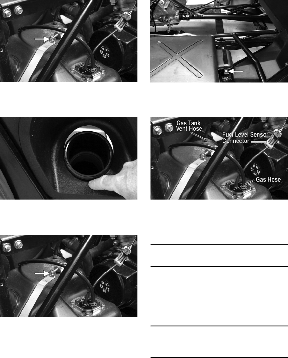
4-10
PR166A
4. Place the gas cap filler panel into position; then
if necessary, position the gas tank so the filler
panel and filler neck are not binding or rubbing.
PR176
5. Secure the filler panel with four press-nuts; then
tighten the hardware securing the hold-down
straps (from steps 2-3) securely.
PR166A
PR167A
6. Connect the gas hose and gas tank vent hose to
the proper fittings; then connect the fuel level
sensor wire connector to the main harness.
PR166B
7. Position the floorboard into the vehicle and
secure with the appropriate hardware; then
install the center console, seat-bases, and seats
making sure the seats lock securely.
Gas/Vent Hoses
Replace the gas hose every two years. Damage from
aging may not always be visible. Do not bend or
obstruct the routing of the carburetor vent hose.
Make certain that the vent hose is securely con-
nected to the carburetor and the opposite end is
always open.
Vacuum Pulse Fuel
Pump
The vacuum pulse fuel pump is a nonserviceable
assembly. If the pump fails, it must be replaced.
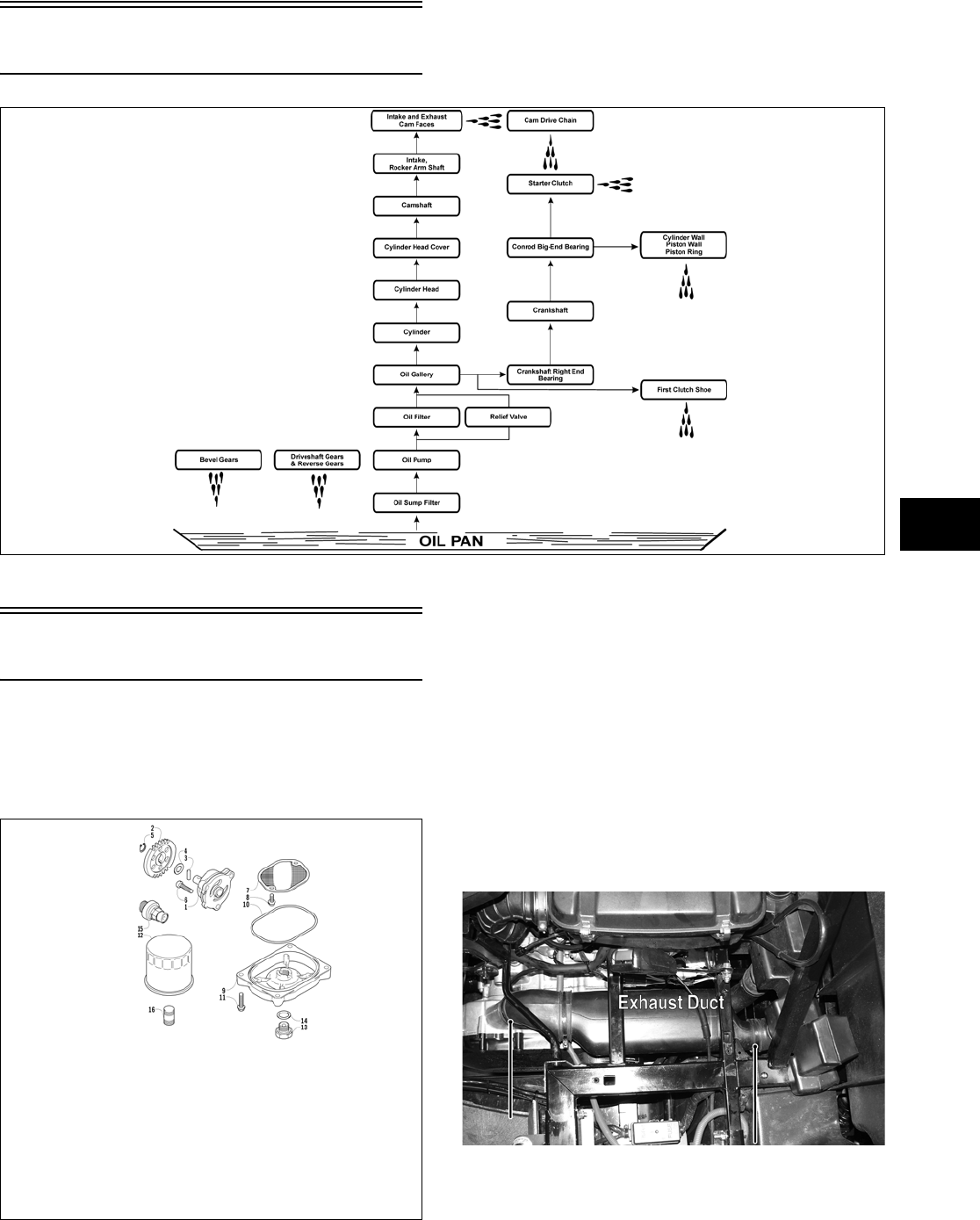
4-11
4
Oil Flow Chart
ATV-1102
Oil Filter/Oil Pump
NOTE: Whenever internal engine components
wear excessively or break and whenever oil is con-
taminated, the oil pump should be disassembled,
cleaned and inspected, and serviced as necessary.
0738-289
TESTING OIL PUMP PRESSURE
NOTE: The engine must be warmed up to the
specified temperature for this test.
1. Remove the seats and center console; then
remove the left-side seat-base.
2. Tilt the cargo box back.
3. Loosen the clamps securing the V-belt housing
exhaust duct; then remove the duct and set
aside.
PR266A
4. Disconnect the upper oil cooler hose; then using
a T-fitting and appropriate adapter, connect the
Oil/Fuel Pressure Gauge (p/n 0644-375) into the
oil cooler circuit.
KEY
1. Oil Pump
2. Driven Gear
3. Pin
4. Washer
5. Circlip
6. Cap Screw
7. Strainer
8. Cap Screw
9. Cap
10. O-Ring
11. Cap Screw
12. Filter
13. Drain Plug
14. Gasket
15. Oil Relief Valve Assy
16. Oil Filter Union
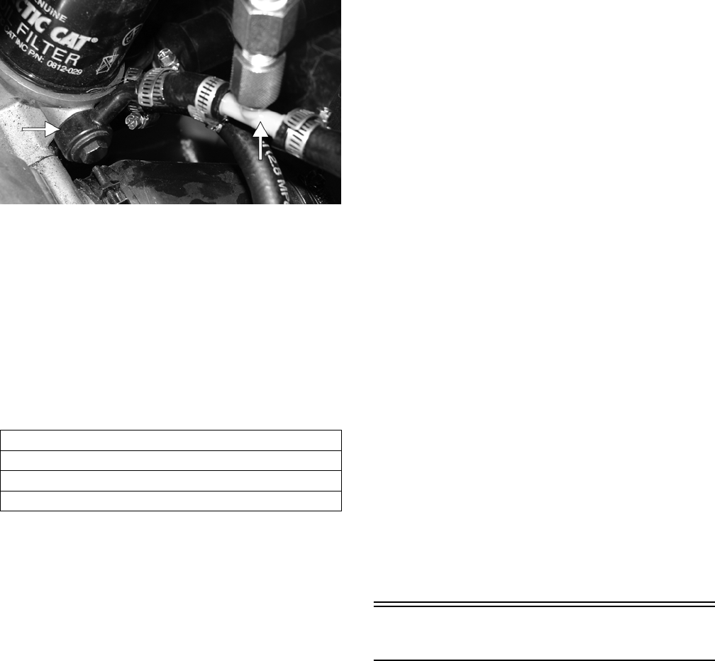
4-12
PR265A
NOTE: Some oil seepage may occur when
installing the oil pressure gauge. Wipe up oil resi-
due with a cloth.
5. Set the parking brake and start the engine.
Allow the engine to warm up to operating tem-
perature (with cooling fan cycling).
6. Set the speedometer/tachometer to RPM. With
the engine running at 2500 RPM, the pressure
gauge must show as specified.
7. Reconnect the oil cooler hose and tighten the
hose clamp securely; then install the V-belt
exhaust duct and tighten the clamps securely.
8. Install the left-side seat-base; then install the
center console and seats making sure the seats
lock securely.
NOTE: If the oil pressure is lower than specified,
check for an oil leak, damaged oil seal, defective
oil pump, or plugged oil cooler (see Checking Oil
Cooler Restriction in the Oil Cooler sub-section).
NOTE: If the oil pressure is higher than speci-
fied, check for too heavy engine oil weight (see
Section 2), clogged oil passage, clogged oil filter,
or improper installation of the oil filter.
REMOVING/DISASSEMBLING
NOTE: Prior to removing the oil pump due to a
low oil pressure reading, check for oil cooler
restrictions (see Checking Oil Cooler Restriction in
the Oil Cooler sub-section).
1. Remove the oil pump from the engine (see
Right-Side Components in Section 3).
2. Remove the Phillips-head screw on the back
side of the pump and separate the pump housing
and cover. Note the position of the inner and
outer rotors and alignment pin for assembly.
3. Remove oil pump components.
CLEANING AND INSPECTING
NOTE: Whenever a part is worn excessively,
cracked, or damaged in any way, replacement is
necessary.
1. Clean all oil-pump components.
2. Inspect the rotors for scoring and gouges.
3. Inspect the alignment pin, driveshaft, and driven
sprocket for damage.
4. Inspect the pump housing and cover for cracks
or damage.
ASSEMBLING/INSTALLING
1. Place the rotors into the pump housing making
sure the alignment pin is in the groove of the
rotor.
2. Place the cover onto the pump housing.
3. Secure the pump with the Phillips-head screw
coated with red Loctite #271.
4. Install the oil pump into the engine (see
Right-Side Components in Section 3).
Oil Cooler
CHECKING OIL COOLER
RESTRICTION
1. Remove the seats, center console, and left-side
seat-base; then remove the V-belt exhaust duct.
Tilt the cargo box back.
2. Disconnect the lower oil cooler hose; then using
a T-fitting and appropriate adapter, connect the
Oil/Fuel Pressure Gauge (p/n 0644-375) into the
oil cooler circuit.
OIL PRESSURE @ 2500 RPM
1.40-2.11 kg/cm²
(20-30 psi)
Operating Temperature (Cooling Fan Cycling)
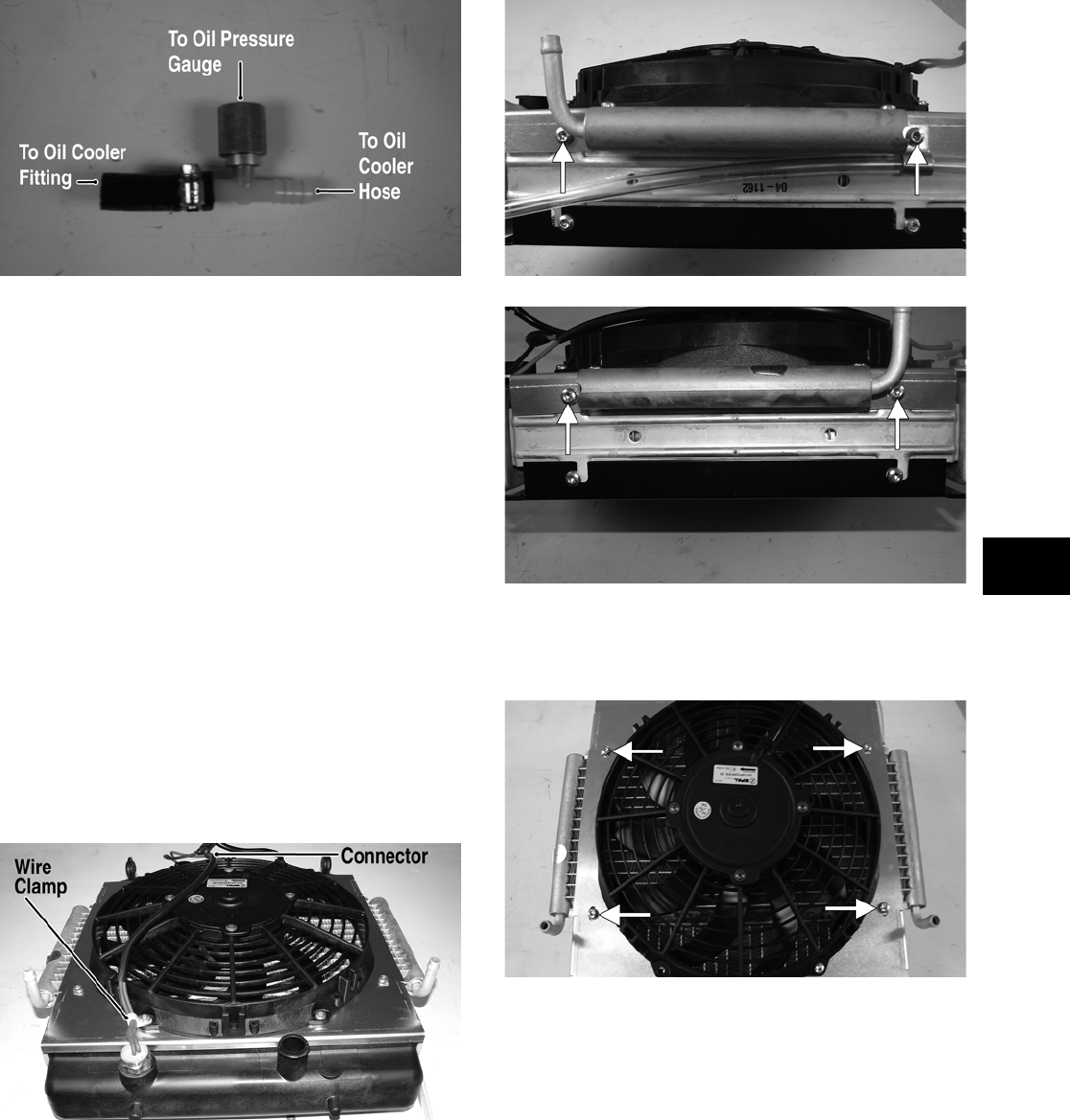
4-13
4
PR267A
3. Set the parking brake and start the engine.
Allow the engine to warm up to operating tem-
perature (with cooling fan cycling).
4. Set the speedometer/tachometer to RPM. With
the engine running at 2500 RPM, the pressure
gauge must show 4.2-5.6 kg/cm2 (60-80 psi).
NOTE: If the gauge readings are normal but low
oil pressure was noted while testing the oil pump
pressure, the oil cooler is plugged and must be
replaced.
REMOVING OIL COOLER
NOTE: The oil cooler is attached to the rear of
the radiator and must be removed as an assembly
(see Radiator/Oil Cooler sub-section).
1. Disconnect the two-wire connector on the cool-
ing fan harness; then remove the machine screw
and wire clamp securing the cooling fan switch
wires.
PR271A
2. Remove four machine screws (two on each side)
securing the fan shroud to the radiator noting
orientation of the fan and oil cooler for assem-
bling.
PR275A
PR268A
3. Remove four machine screws securing the oil
cooler to the fan shroud and remove the oil
cooler.
PR273A
INSTALLING OIL COOLER
1. Place the oil cooler on a clean flat surface; then
position the fan shroud over the oil cooler mak-
ing sure the fan wires are directed toward the top
of the shroud and the oil cooler connections are
directed toward the bottom of the shroud.
Secure with four machine screws.
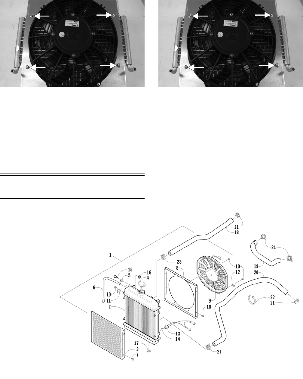
4-14
PR273A
2. Place the radiator on a flat surface (front side
down); then position the oil cooler/cooling fan
assembly onto the radiator with the oil cooler
connections directed toward the bottom of the
radiator. Secure with four machine screws mak-
ing sure to install the radiator overflow hose
hold-down clip on the upper-right machine
screw.
PR273A
3. Connect the cooling fan harness to the cooling
fan connector; then secure the cooling fan har-
ness wire clamp with the machine screw.
Liquid Cooling System
0739-654
The cooling system should be inspected daily for
leakage and damage. Also, the coolant level should
be checked periodically.
KEY
1. Radiator Assy
2. Radiator
3. Radiator Screen
4. Radiator Cap
5. Grommet
6. Vent Hose
7. Thumb Screw
8. Fan Shroud
9. Fan
10. Machine Screw
11. Clamp
12. Clamp
13. Temperature Sender
14. O-Ring
15. Shoulder Screw
16. Nut w/Washer
17. Stem Bushing
18. Coolant Hose
19. Coolant Hose
20. Coolant Hose
21. Hose Clamp
22. Cable Tie
23. Hose Clamp
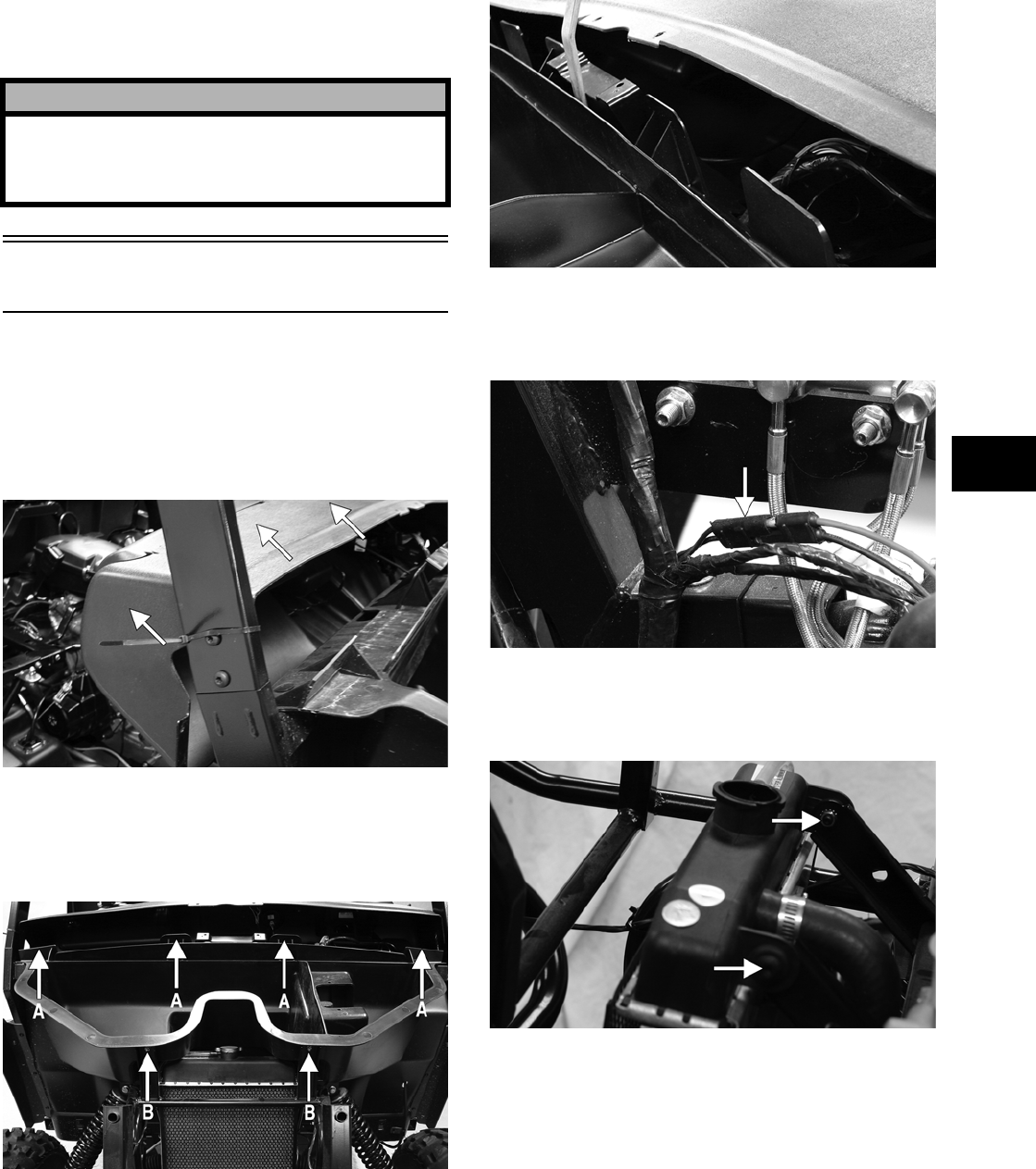
4-15
4
When filling the cooling system, use premixed Arc-
tic Cat Antifreeze (p/n 0638-395). While the cooling
system is being filled, air pockets may develop;
therefore, run the engine for five minutes after the
initial fill, shut the engine off, and then fill the cool-
ing system to the bottom of the stand pipe in the
radiator neck.
Radiator/Oil Cooler
REMOVING
1. Remove six torx-head screws securing the dash
assembly to the frame; then remove the parking
brake release handle and jam nut. Slide the dash
rearward approximately four inches.
PR181A
2. Remove four torx-head screws (A) securing the
under-hood storage box to the frame; then
remove two cap screws with nuts (B) at the front
of the storage box.
PR182A
3. While lifting up on the front of the storage box,
pry the rear center clear of the center dash
mount and remove the storage box.
PR186
4. Drain the coolant into a suitable container; then
disconnect the cooling fan wire connector from
the main harness.
PR183A
5. Remove the two shoulder bolts and nuts secur-
ing the radiator to the frame; then disconnect the
upper and lower coolant hoses.
PR184A
6. Place a shallow container under the right-side
oil cooler hose; then remove the hose from the
oil cooler.
! CAUTION
After operating the vehicle for the initial 5-10 min-
utes, stop the engine, allow the engine to cool
down, and check the coolant level. Add coolant as
necessary.
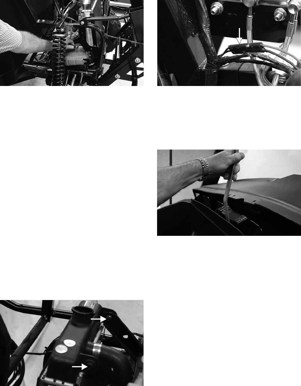
4-16
PR185
7. Allow the oil cooler to drain; then remove the
left-side oil cooler hose.
8. Lift the radiator/oil cooler assembly from the
vehicle. Account for two upper and two lower
rubber mounting grommets.
CLEANING AND INSPECTING
NOTE: Whenever a part is worn excessively,
cracked, or damaged in any way, replacement is
necessary.
1. Flush the radiator with water to remove any con-
taminants.
2. Inspect the radiator for leaks and damage.
3. Inspect all hoses for cracks and deterioration.
4. Inspect all fasteners and grommets for damage
or wear.
INSTALLING
1. Place the radiator/oil cooler into position mak-
ing sure the grommets are correctly installed;
then secure to the mounts with the two shoulder
bolts and nuts. Tighten securely.
PR184A
2. Connect the upper and lower radiator hoses and
the left and right oil cooler hoses to the radia-
tor/oil cooler and secure with the appropriate
hose clamps; then connect the cooling fan con-
nector to the main harness.
PR183A
3. Pour the recommended coolant into the radiator
and secure the radiator cap.
4. Place the storage box into position and using a
smooth, flat pry-bar, pry the center of the box
past the dash mount; then secure with the appro-
priate fasteners.
PR187
5. Slide the dash forward into position while guid-
ing the parking brake release rod through the
hole; then secure the dash with the appropriate
hardware.
6. Install the jam-nut and parking brake release
handle; then tighten the jam-nut so the handle is
correctly oriented.
7. Set the parking brake; then start the engine and
let idle for approximately one minute to fill the
oil cooler. Shut the engine off and add oil to the
crankcase as required to the specified level (see
Section 2).
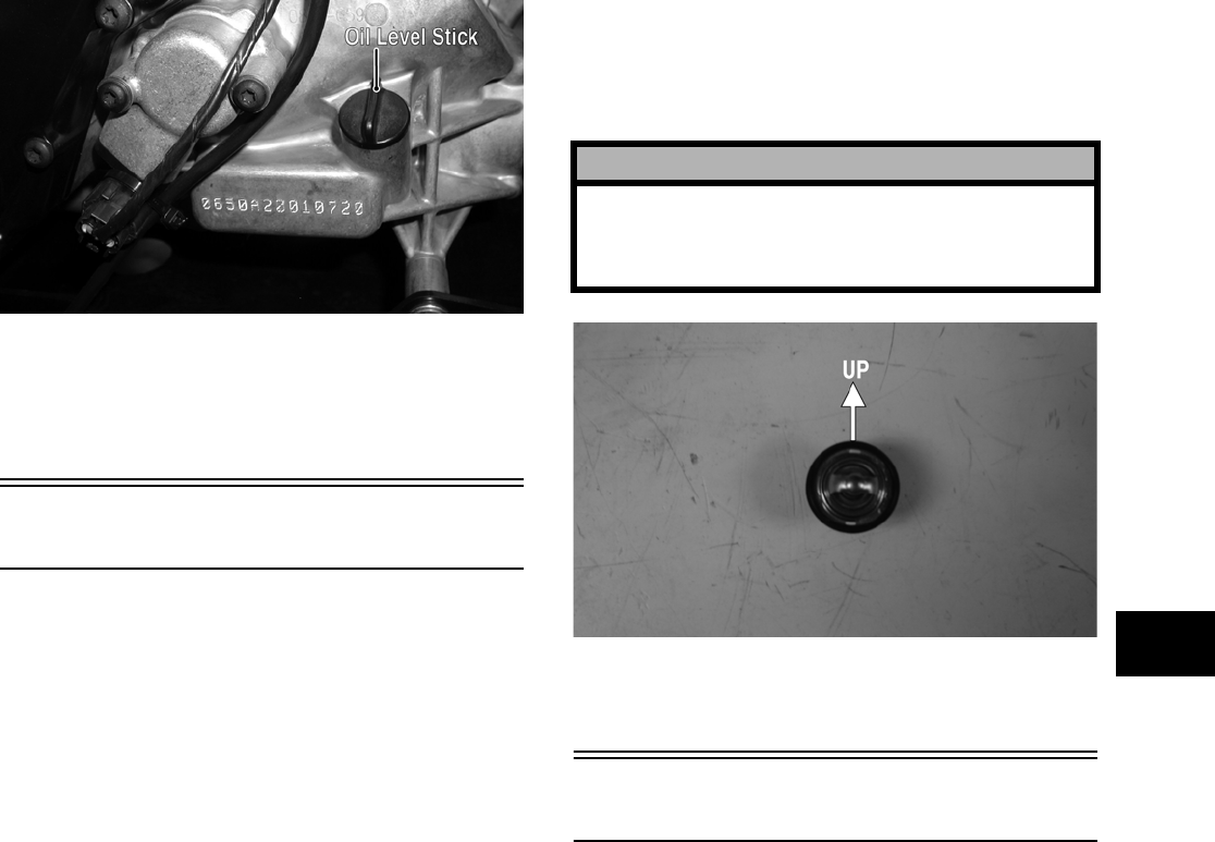
4-17
4
PR053B
8. Start the engine and warm up to operating tem-
perature; then check that the coolant level is at
the specified level (see Section 2). Add coolant
as required.
Thermostat
REMOVING
1. Drain approximately one quart of coolant from
the cooling system.
2. Remove the two cap screws securing the ther-
mostat housing to the cylinder head. Account for
a thermostat with seal.
INSPECTING
NOTE: Whenever a part is worn excessively,
cracked, or damaged in any way, replacement is
necessary.
1. Inspect the thermostat for corrosion, wear, or
spring damage.
2. Using the following procedure, inspect the ther-
mostat for proper operation.
A. Suspend the thermostat in a container filled
with water.
B. Heat the water and monitor the temperature
with a thermometer.
C. The thermostat should start to open at
73.5-76.5°C (164-170°F).
D. If the thermostat does not open, it must be
replaced.
3. Inspect all coolant hoses, connections, and
clamps for deterioration, cracks, and wear.
NOTE: All coolant hoses and clamps should be
replaced every four years or 4000 miles.
INSTALLING
1. Place the thermostat into the thermostat hous-
ing; then secure the thermostat housing to the
cylinder head with the two cap screws.
PR281A
2. Fill the cooling system with the recommended
amount of antifreeze. Check for leakage.
Fan
REMOVING
1. Remove the radiator (see Radiator/Oil Cooler in
this section).
2. Remove the fan assembly from the radiator.
INSTALLING
1. Position the fan assembly on the radiator; then
secure with existing hardware.
NOTE: The fan wiring must be in the upper-right
position.
2. Install the radiator (see Radiator/Oil Cooler in
this section).
! CAUTION
When installing the thermostat, make sure the
bleed holes are straight up and down or air will
remain trapped causing engine damage due to
overheating.
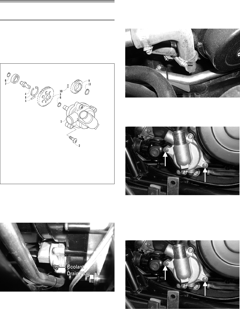
4-18
Water Pump
NOTE: The water pump is not a serviceable
component. If the pump is defective or if the
mechanical seal is leaking (coolant dripping from
the discharge hole), the water pump must be
replaced.
0739-945
REMOVING
1. Remove the radiator cap; then remove the water
pump coolant drain plug and drain the coolant.
PR122A
2. Drain the oil from the engine/transmission.
3. Remove the seats and center console; then
remove the right-side seat-base.
4. Loosen the coolant hose clamps and slide the
clamps away from the hose ends approximately
51 mm (2 in.); then remove both hoses from the
water pump.
PR132
5. Remove the two cap screws securing the water
pump to the engine; then remove the water
pump.
CC786A
INSTALLING
1. Secure the water pump to the engine with the
two cap screws tightened securely; then tighten
the two Phillips-head cap screws securely.
CC786A
KEY
1. Water Pump Assy
2. Screw
3. Driven Gear
4. Shaft
5. Pin
6. Circlip
7. Bearing
8. Circlip
9. Drive Gear
10. Pin
11. Circlip
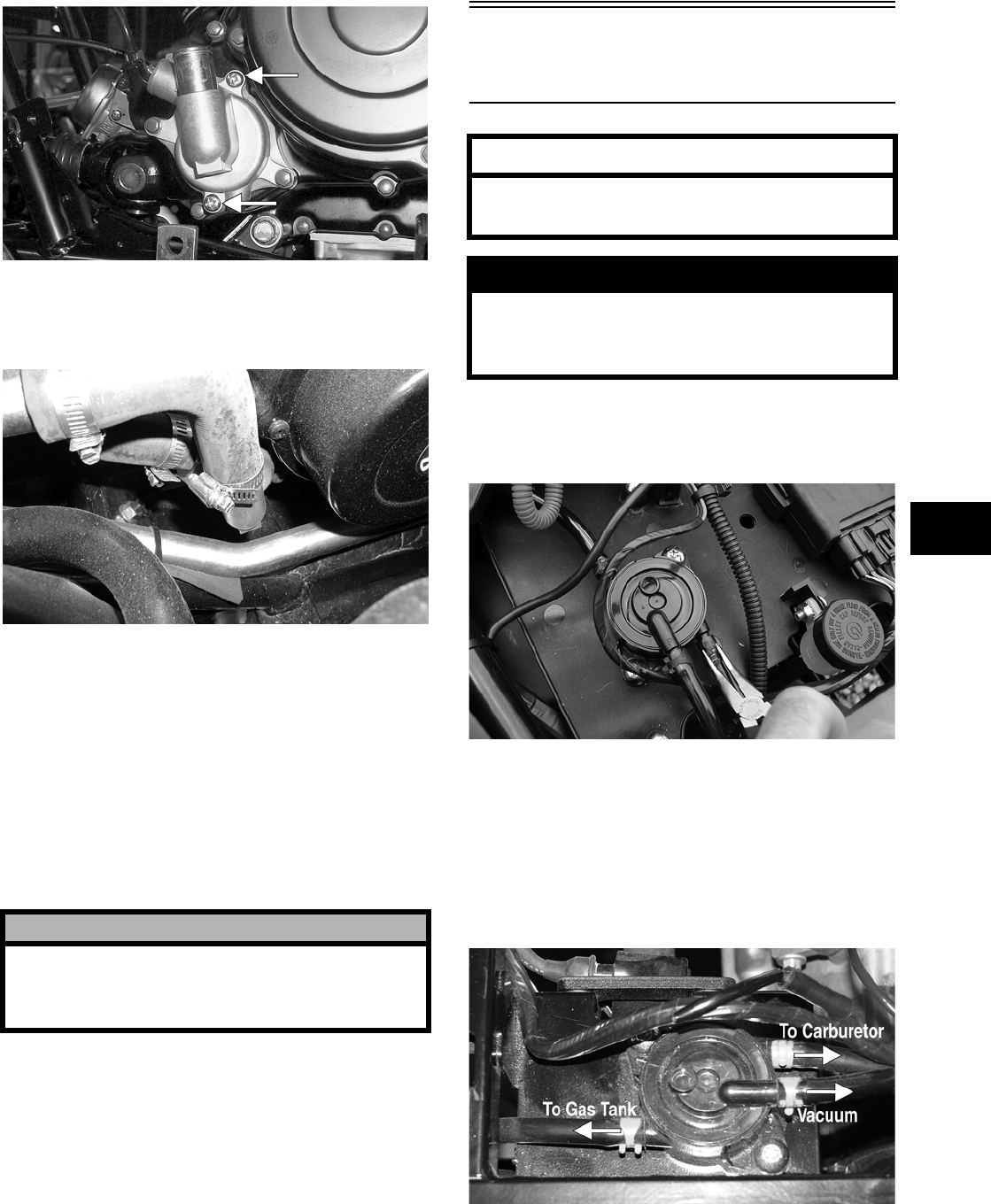
4-19
4
CC785A
2. Connect the two coolant hoses to the water
pump and secure with the clamps; then install
the water pump coolant drain plug.
PR132
3. Fill the engine/transmission with the proper
amount of recommended oil.
4. Fill the cooling system with the proper amount
of recommended coolant.
NOTE: While the cooling system is being filled,
air pockets may develop; therefore, run the engine
for five minutes after the initial fill, shut the engine
off, and then fill the cooling system.
5. Check the entire cooling system for leakage.
6. Install the right-side seat-base; then install the
center console and seats making sure the seats
lock securely.
Testing Vacuum Pulse
Fuel Pump
1. Disconnect the fuel pump/carburetor hose at the
fuel pump; then connect a hose and suitable
pressure gauge to the fuel pump output fitting.
CD815
2. Start the engine. Fuel pump pressure should
show 0.036-0.084 kg/cm2 (0.5-1.2 psi).
REMOVING
1. Remove the right-side seat-base; then remove
the three clamps securing the gas hoses and vac-
uum hose and disconnect the hoses.
PR280A
! CAUTION
After operating the vehicle for the initial 5-10 min-
utes, stop the engine, allow the engine to cool
down, and check the coolant level. Add coolant as
necessary.
AT THIS POINT
Prior to removing the vacuum pulse fuel pump,
the following check should be performed to
determine that removal is necessary.
! WARNING
Whenever any maintenance or inspection is made
on the fuel system during which there may be fuel
leakage, there should be no welding, smoking,
open flames, etc., in the area.
4-20
2. Remove the two machine screws and flange nuts
securing the fuel pump to the electrical tray;
then remove the pump.
INSTALLING
1. Place the fuel pump into position on the electri-
cal tray; then secure with the machine screws
and flange nuts. Tighten securely.
2. Connect two gas hoses and one vacuum hose;
then secure with the clamps.

5-1
5
SECTION 5 —
ELECTRICAL SYSTEM
TABLE OF
CONTENTS
Specifications …..…………….…………….…………….….. 5-2
Battery…………….………….…………….…………….…….. 5-3
RPM Limiter.………….…………….…………….…………… 5-3
Testing Electrical Components …………..……………... 5-3
Accessory Receptacle/Connector …………….……….. 5-4
Brakelight Switch………………….…………….…………... 5-4
Coolant Temperature and Cooling Fan Switches …. 5-4
Fan Motor …………..………….…………….…………….….. 5-5
Power Distribution Module..…………….…………….….. 5-6
Fuses …………..………………………..…………….……….. 5-6
Ignition Coil …………..…………….………….……………... 5-6
Speed Sensor ……….…………….…………….…………… 5-7
Ignition Switch .…………….………….…………….……….. 5-8
Dash Switches ………………….…………….……………... 5-8
Center Console Switch……….…………….……………... 5-9
Front Drive Selector Actuator …………….……………... 5-9
Differential Lock Switch …………………….……………. 5-10
Magneto Coils …….…………….…………….………….… 5-10
Starter Motor ………………….………….…………….…… 5-12
Starter Relay ……………………….…………….…………. 5-12
CDI Unit…………..………….…………….…………….…… 5-13
Regulator/Rectifier…….……………..…………….……… 5-13
Neutral Start/Start-in-Gear/2WD Relays …………… 5-13
Headlights ………….…………….…………….……………. 5-14
Taillight-Brakelight …….………………..……………….… 5-14
Ignition Timing.…………….…………….………….……… 5-14

5-2
Specifications
Prowler XT
IGNITION
Ignition Timing 10° BTDC @ 1500 RPM
Spark Plug Type Champion R6YCA
Spark Plug Gap 0.7-0.8 mm
(0.028-0.032 in.)
Spark Plug Cap 4000-6000 ohms
Ignition Coil
Resistance
(primary)
(secondary)
Less than 1 ohm
(terminal to ground)
5200-7800 ohms
(high tension — plug cap
removed — to ground)
Ignition Coil Peak
Voltage (static)
(primary/CDI) 132-198 DC volts
(terminal to ground)
MAGNETO
Magneto Coil
Resistance
(trigger)
(source)
(charging)
160-240 ohms
(green to blue)
Less than 1 ohm
(yellow to white)
Less than 1 ohm
(black to black)
Magneto Coil
Peak Voltage
(trigger)
(source)
4.2-6.3 volts
(green to blue)
0.40-0.62 volt
(yellow to white)
Stator Coil Output (no load) 60 AC volts @ 5000
RPM
(black to black #1)
(black to black #2)
Magneto Output (approx) 325W @ 5000 RPM
5-3
5
Battery
1. Remove the battery from the vehicle.
2. Remove the vent plugs; then fill the battery with
electrolyte to the UPPER level indicated on the
battery.
NOTE: Electrolyte should be at room tempera-
ture before filling. Do not use water or any other
liquid to activate a battery.
3. Allow the battery to stand for 15-30 minutes
after filling. Electrolyte level may fall during
this time. Refill with electrolyte to UPPER level
line.
4. Trickle-charge the battery at 1.5A for 8-10
hours.
5. After charging, check electrolyte level and fill
with DISTILLED WATER as necessary; then
install the vent plugs. Wash off acid spillage
with water and dry the battery.
6. Place the battery into position in the vehicle and
secure; then connect the vent hose to the battery.
7. Connect cables to the proper terminals: positive
cable to the positive terminal (+) and negative
cable to the negative terminal (-). Connect the
negative cable last.
8. Check the vent tube to make sure it is not
pinched or obstructed in any way and that it is
properly routed down through the frame.
RPM Limiter
NOTE: The Prowler XT is equipped with a CDI
unit that retards ignition timing when maximum
RPM is approached. When the RPM limiter is acti-
vated, it could be misinterpreted as a high-speed
misfire.
Testing Electrical
Components
All of the electrical tests should be made using the
Fluke Model 73 Multimeter (p/n 0644-191) and
when testing peak voltage, the Peak Voltage Read-
ing Adapter (p/n 0644-307) must be used. If any
other type of meter is used, readings may vary due
to internal circuitry. When troubleshooting a spe-
cific component, always verify first that the fuse(s)
are good, that the bulb(s) are good, that the connec-
tions are clean and tight, that the battery is fully
charged, and that all appropriate switches are acti-
vated.
NOTE: For absolute accuracy, all tests should be
made at room temperature of 68° F.
! WARNING
Anytime service is performed on a battery, the fol-
lowing must be observed: keep sparks, open flame,
cigarettes, or any other flame away. Always wear
safety glasses. Protect skin and clothing when han-
dling a battery. When servicing battery in enclosed
space, keep the area well-ventilated. Make sure
venting tube of battery is always open once battery
is filled with electrolyte.
! WARNING
Remove the negative cable first; then remove the
positive cable.
! CAUTION
Do not charge the battery while it is in the vehicle
with the battery terminals connected.
! WARNING
Electrolyte is a sulfuric acid solution. Avoid spillage
and contact with skin, eyes, and clothing.
! CAUTION
Before installing the battery, make sure the ignition
switch is in the OFF position.
! CAUTION
Connecting cables in reverse (positive to negative
and negative to positive) can cause serious dam-
age to the electrical system.
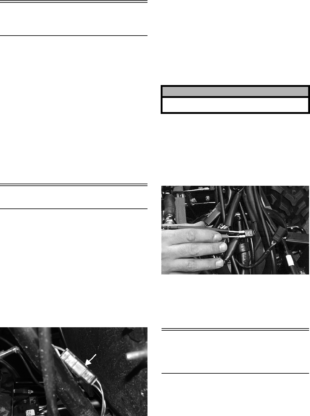
5-4
Accessory
Receptacle/Connector
NOTE: This test procedure is for either the
receptacles or the connectors.
VOLTAGE
1. Turn the ignition switch to the ON position; then
set the meter selector to the DC Voltage posi-
tion.
2. Connect the red tester lead to the red/white wire
or the positive connector; then connect the black
tester lead to ground.
3. The meter must show battery voltage.
NOTE: If the meter shows no battery voltage,
troubleshoot the battery, fuse, receptacle, connec-
tor, or the main wiring harness.
Brakelight Switch
The switch connector is the two-prong black con-
nector below the master cylinder.
NOTE: The ignition switch must be in the ON
position.
VOLTAGE
(Wiring Harness Connector)
1. Set the meter selector to the DC Voltage posi-
tion.
2. Connect the red tester lead to the orange wire;
then connect the black tester lead to ground.
PR276A
3. The meter must show battery voltage.
NOTE: If the meter shows no battery voltage,
troubleshoot the battery, fuse, switch, or the main
wiring harness.
NOTE: If the meter shows battery voltage, the
main wiring harness is good; proceed to test the
switch/component, the connector, and the switch
wiring harness for resistance.
RESISTANCE
(Switch Connector)
NOTE: The brake pedal must be depressed for
this test.
1. Set the meter selector to the OHMS position.
2. Connect the red tester lead to one black wire;
then connect the black tester lead to the other
black wire.
AR621D
3. When the lever is depressed, the meter must
show less than 1 ohm.
NOTE: If the meter shows more than 1 ohm of
resistance, replace the switch.
Coolant Temperature
and Cooling Fan
Switches
1. Connect the meter leads (selector in the OHMS
position) to the switch contacts.
2. Suspend the switch and a thermometer in a con-
tainer of water; then heat the water.
! CAUTION
Always disconnect the battery when performing
resistance tests to avoid damaging the multimeter.
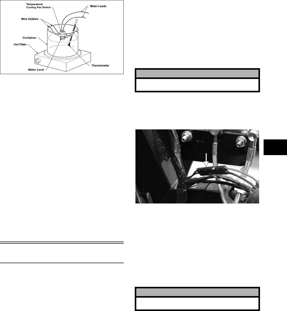
5-5
5
NOTE: Neither the switch nor the thermometer
should be allowed to touch the bottom of the con-
tainer or inaccurate readings will occur. Use wire
holders to suspend switch and thermometer.
733-554E
3. On the coolant temperature switch when the
water temperature reaches 112-118° C
(234-244° F), the meter should show a closed
circuit.
4. On the coolant temperature switch, allow the
water to cool, and when the temperature is
within a temperature range of 107-113° C
(225-235° F), the meter should show an open
circuit.
5. On the cooling fan switch when the temperature
reaches 81-99° C (175-213° F), the meter should
show a closed circuit.
6. On the cooling fan switch, allow the water to
cool, and when the temperature is within a tem-
perature range of 67-82° C (150-184° F), the
meter should show an open circuit.
7. If the readings are not as indicated, the switch
must be replaced.
8. Install the switch and tighten securely.
9. Connect the switch leads.
Fan Motor
NOTE: The ignition switch must be in the ON
position.
VOLTAGE
(Main Harness Connector to Fan
Motor)
1. Set the meter selector to the DC Voltage posi-
tion.
2. Connect the red tester lead to the black/red wire
(the black 2-prong at the fan motor); then con-
nect the black tester lead to ground.
3. The meter must show battery voltage.
NOTE: If the meter shows no battery voltage,
troubleshoot the battery, fuse, motor, or the main
wiring harness.
NOTE: If the meter shows battery voltage, the
main wiring harness is good. The connector
should be checked for resistance.
RESISTANCE
(Fan Motor Connector)
1. Set the meter selector to the OHMS position.
2. Connect the red tester lead to the red wire; then
connect the black tester lead to the black wire.
PR183A
3. The meter must show less than 1 ohm.
NOTE: If the meter shows more than 1 ohm of
resistance, troubleshoot or replace the
switch/component, the connector, or the switch
wiring harness.
NOTE: To determine if the fan motor is good,
connect the red wire from the fan connector to a 12
volt DC power supply; then connect the black wire
from the fan connector to ground. The fan should
operate.
! CAUTION
Always disconnect the battery when performing
resistance tests to avoid damaging the multimeter.
! CAUTION
Care should be taken to keep clear of the fan
blades.
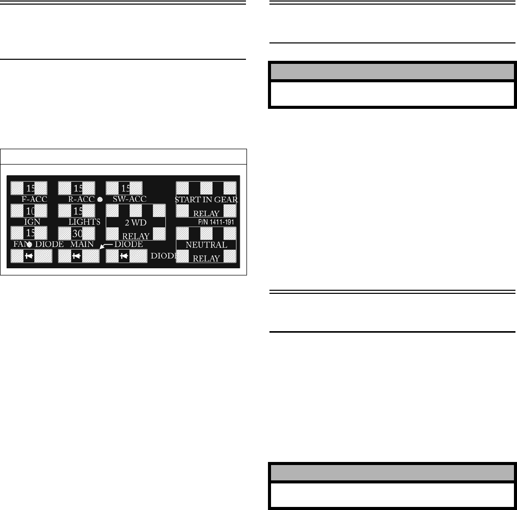
5-6
Power Distribution
Module
The fuses are located in a power distribution module
under the driver’s seat.
If there is any type of electrical system failure,
always check the fuses first.
1411-191
1. Remove all fuses from the power distribution
module.
2. Set the meter selector to the DC Voltage posi-
tion.
3. Connect the black tester lead to ground.
4. Using the red tester lead, contact each end of the
fuse holder connector terminals individually.
5. The meter must show battery voltage from one
side of the connector terminal ends.
NOTE: Battery voltage will be indicated from
only one side of the fuse holder connector termi-
nal; the other side will show no voltage.
NOTE: When testing the HI fuse holder, the head-
light OFF/HI/LO switch must be in the HI position;
when testing the LIGHTS fuse holder, the headlight
dimmer switch can be in either the HI or the LO
position.
NOTE: If the meter shows no battery voltage,
troubleshoot the battery, switches, power distribu-
tion module, or the main wiring harness.
Fuses
1. Set the meter selector to the OHMS position.
2. Connect the red tester lead to one spade end of
the fuse; then connect the black tester lead to the
other spade end.
3. The meter must show less than 1 ohm resis-
tance. If the meter shows open, replace the fuse.
NOTE: Make sure the fuses are returned to their
proper position according to amperage. Refer to
the amperage listed under each fuse on the power
distribution module.
Ignition Coil
The ignition coil is mounted on the fuel pump
mounting plate adjacent to the fuel pump.
VOLTAGE (Primary Side)
See PEAK VOLTAGE Primary/CDI this sub-sec-
tion.
RESISTANCE
NOTE: For these tests, the meter selector should
be set to the OHMS position.
Primary Winding
1. Connect the red tester lead to the terminal (with
the wire removed); then connect the black tester
lead to ground.
Prowler XT
! CAUTION
Always disconnect the battery when performing
resistance tests to avoid damaging the multimeter.
! CAUTION
Always disconnect the battery when performing
resistance tests to avoid damaging the multimeter.
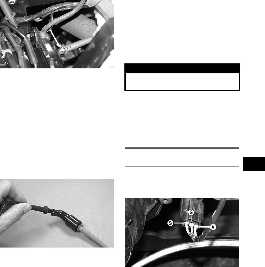
5-7
5
PR278A
2. The meter reading must be within specification.
Secondary Winding
1. Connect the red tester lead to the high tension
lead (with the plug cap removed); then connect
the black tester lead to ground.
2. The meter reading must be within specification.
NOTE: If the meter does not show as specified,
replace ignition coil.
Spark Plug Cap
1. Connect the red tester lead to one end of the cap;
then connect the black tester lead to the other
end of the cap.
AR603D
2. The meter reading must be within specification.
NOTE: If the meter does not show as specified,
replace the spark plug cap.
PEAK VOLTAGE
NOTE: All of the peak voltage tests should be
made using the Fluke Model 73 Multimeter (p/n
0644-191) with Peak Voltage Reading Adapter (p/n
0644-307). If any other type of tester is used, read-
ings may vary due to internal circuitry.
NOTE: The battery must be at full charge for
these tests.
Primary/CDI
NOTE: The CDI is located beneath the driver’s
seat above the battery.
1. Set the meter selector to the DC Voltage posi-
tion; then disconnect the blue/white primary
wire from the coil.
2. Connect the red tester lead to the primary wire;
then connect the black tester lead to ground.
3. Turn the ignition switch to the ON position.
4. The meter must show 132-198 DC volts.
5. With the test leads still connected, crank the
engine with the electric starter.
6. The meter must show 300-450 DC volts.
Speed Sensor
NOTE: Prior to testing the speed sensor, inspect
the three-wire connector on the speed sensor for
contamination, broken pins, and/or corrosion.
PR279A
1. Set the meter selector to the DC Voltage posi-
tion.
2. With appropriate needle adapters on the meter
leads, connect the red tester lead to the voltage
lead (V); then connect the black tester lead to
the ground lead (G).
3. Turn the ignition switch to the ON position.
4. The meter must show approximately 6 DC volts.
! WARNING
Do not touch the primary wire with the ignition
switch turned on or severe electrical shock will
occur.
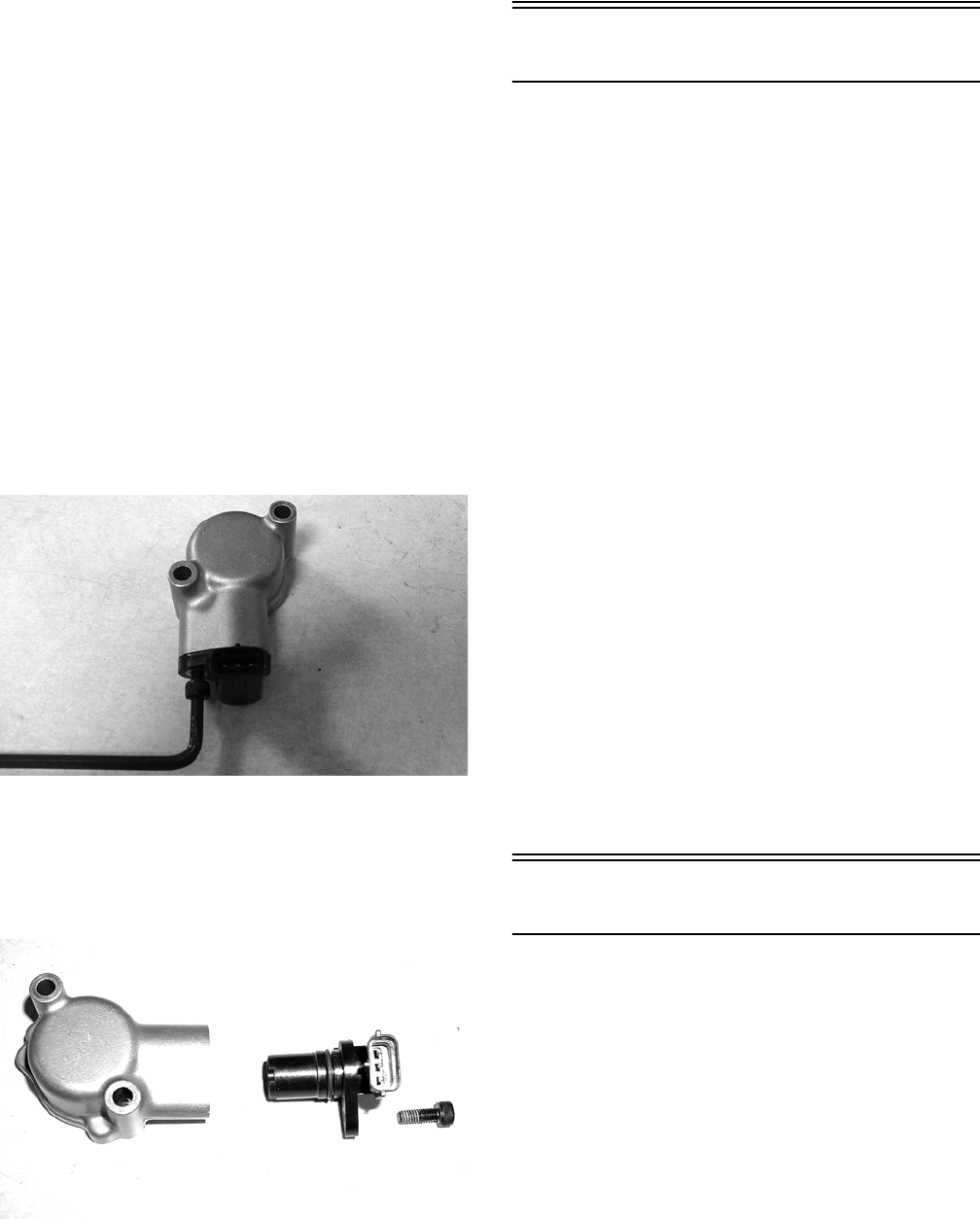
5-8
5. Leave the black tester lead connected; then con-
nect the red tester lead to the signal lead (S) pin.
6. Slowly move the vehicle forward or backward;
the meter must show 0 and approximately 6 DC
volts alternately.
NOTE: If the sensor tests are within specifica-
tions, the speedometer must be replaced. See Sec—
tion 9.
To replace a speed sensor, use the following proce-
dure.
1. Disconnect the three-wire connector from the
speed sensor harness or from the speed sensor;
then remove the Allen-head cap screw securing
the sensor to the sensor housing.
2. Remove the sensor from the sensor housing
accounting for an O-ring.
CD070
3. Install the new speed sensor into the housing
with new O-ring lightly coated with multi-pur-
pose grease; then secure the sensor with the
Allen-head cap screw (threads coated with blue
Loctite #242). Tighten securely.
CD071
Ignition Switch
To access the ignition switch, dash switches, front
accessory connectors, and front switched accessory
connector, the dash must be unfastened and slid to the
rear.
VOLTAGE
1. Set the meter selector to the DC Voltage posi-
tion.
2. Connect the red meter lead to the red wire; then
connect the black meter lead to ground.
3. Meter must show battery voltage.
NOTE: If the meter shows no battery voltage,
troubleshoot the main 30 amp fuse, the battery, or
the main wiring harness.
4. Connect the red meter lead to the red/black wire;
then with the black lead grounded, turn the igni-
tion switch to the ON position. The meter must
show battery voltage.
5. Connect the red meter lead to the yellow/green
wire; then with the black lead grounded, turn the
ignition switch to the START position. The
starter should engage and the meter must show
battery voltage.
NOTE: When the starter is engaged, battery volt-
age will be approximately 10.5 DC volts.
Dash Switches
VOLTAGE (Headlight Switch)
1. Connect the red meter lead to the gray wire; then
connect the black meter lead to the black wire.
2. Turn the ignition switch to the ON position. The
meter must show battery voltage.
NOTE: If the meter does not show battery volt-
age, troubleshoot the LIGHTS fuse on the power
distribution module, the ignition switch, or the
main harness.
3. Connect the red meter lead to the yellow wire;
then select the high beam position on the head-
light switch. The meter must show battery volt-
age.
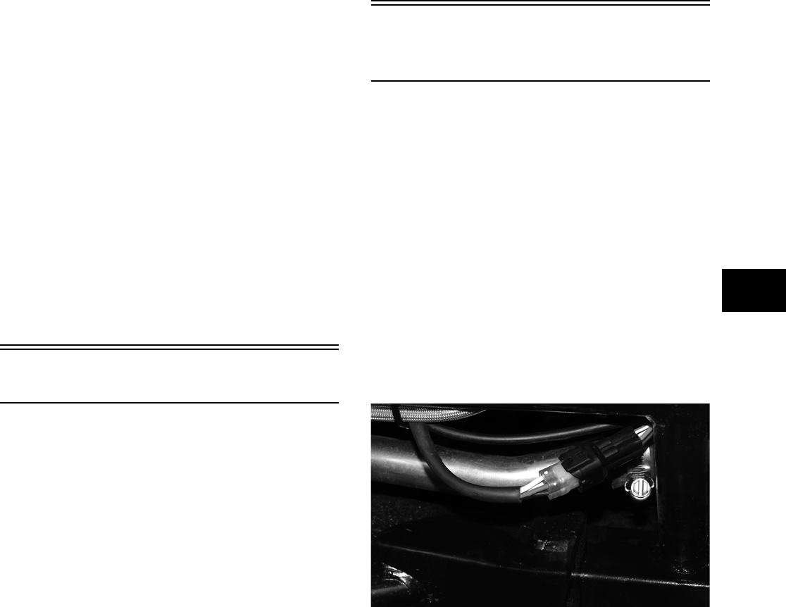
5-9
5
4. Connect the red meter lead to either of the two
white wires; then select the low beam position
on the headlight switch. The meter must show
battery voltage.
NOTE: The battery voltage will show lower in
steps 3 and 4 due to electrical loading of the head-
lights.
VOLTAGE
(2WD/4WD Selector Switch)
1. Connect the red meter lead to the gray wire; then
connect the black meter lead to the black wire.
Turn the ignition switch to the ON position. The
meter must show battery voltage.
NOTE: If the meter does not show battery volt-
age, troubleshoot the LIGHTS fuse on the power
distribution module, the ignition switch, or the
main wiring harness.
2. Connect the red meter lead to the white/red
wire; then select 2WD on the selector switch.
The meter must show battery voltage.
3. Connect the red meter lead to the white/green
wire. The meter must show approximately 9.5
DC volts.
4. Select 4WD on the selector switch. The meter
must show 0 DC volts.
Center Console Switch
VOLTAGE (Reverse Override
Switch)
NOTE: To perform the following tests, the igni-
tion switch must be in the ON position and the
transmission shifted into reverse gear.
1. Connect the red meter lead to the black/blue
wire and the black meter lead to a suitable
ground; then select 2WD on the 2WD/4WD
selector switch. The meter must show approxi-
mately 1.5 DC volts.
2. Depress the reverse override switch. The meter
showing should not change from step 1.
3. Select 4WD on the 2WD/4WD selector switch.
The meter must show approximately 5 DC volts.
4. Depress the reverse override switch. The meter
must show approximately 1.5 DC volts.
5. Connect the red meter lead to the red/yellow
wire. The meter must show approximately 1.5
DC volts. Depress the reverse override switch.
The meter must show approximately 1.5 DC
volts.
6. Connect the red meter lead to the red/green wire.
The meter should show 0 DC volts.
7. Depress the reverse override switch. The meter
must show approximately 5 DC volts.
Front Drive Selector
Actuator
NOTE: With the engine stopped and the ignition
switch in the ON position, a momentary “whirring”
sound must be noticeable each time the selector
switch is moved to 2WD and 4WD. Test the switch,
30 amp fuse, and wiring connections prior to test-
ing the actuator.
NOTE: The differential must be in the unlocked
position for this procedure.
VOLTAGE
1. Locate the 4-wire connector for the front drive
selector actuator on the frame to the right of the
differential; then connect the red meter lead to
the orange wire using a MaxiClip (p/n
0744-041).
PR293
2. Connect the black lead to the black wire using a
MaxiClip (p/n 0744-041); then select 2WD on
the 2WD/4WD selector switch.
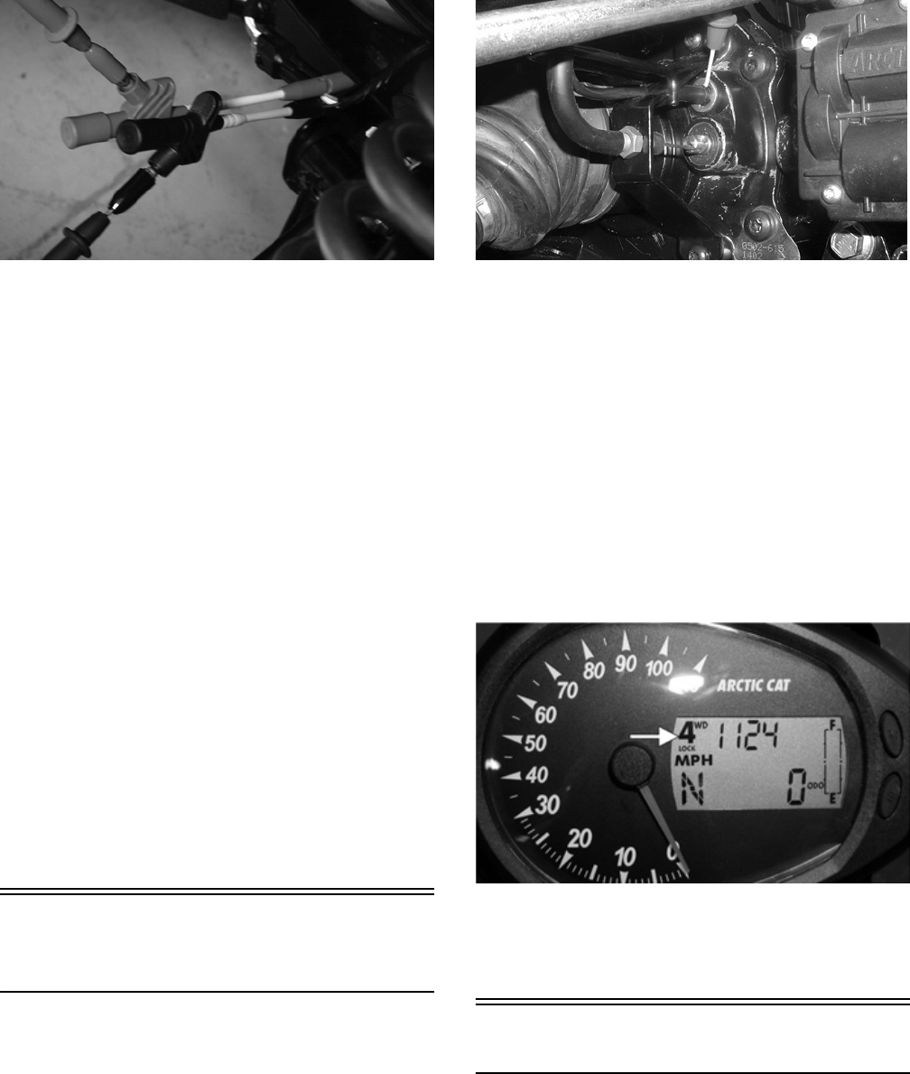
5-10
PR295
NOTE: The black tester lead can remain con-
nected to the black wire for the remaining tests.
3. Turn the ignition switch to the ON position. The
meter must show battery voltage.
NOTE: If battery voltage is not shown, trouble-
shoot the 10 amp IGNITION fuse on the power dis—
tribution module, the ignition switch, or the main
wiring harness.
4. Connect the red meter lead to the white/red
wire. The meter must show battery voltage.
5. Select 4WD on the 2WD/4WD selector switch.
The meter must show 0 DC volts.
6. Connect the red meter lead to the white/orange
wire. The meter must show battery voltage.
7. Engage the differential lock. The meter must
show 0 DC volts.
NOTE: If the meter does not show 0 DC volts,
rock the vehicle to help engage the differential
lock; then troubleshoot the differential lock switch
(see Differential Lock Switch in this section).
Differential Lock
Switch
VOLTAGE
1. Select DC Voltage on the multimeter; then con-
nect the red tester lead to the switch terminal
(leaving the wire connected) and the black tester
lead to ground.
CD575
2. Turn the ignition switch to the ON position. The
meter must show 12 DC volts.
NOTE: If no voltage is indicated, check the wiring
harness, fuse, or battery connections.
3. Select the lock position on the differential. The
meter should drop to 0 volts, and the front drive
actuator should operate to engage 4-wheel drive.
NOTE: It may be necessary to rock the vehicle
slightly to engage the differential lock fully.
NOTE: The 4WD and LOCK icons in the
upper-left corner of the LCD should illuminate.
CF094C
4. If the differential lock engages (front wheels
locked) and the voltage does not drop to 0, the
switch is faulty and must be cleaned or replaced.
Magneto Coils
VOLTAGE (Charging Coil — Output)
1. Set the meter selector to the DC Voltage posi-
tion.
2. Connect the red tester lead to the positive bat-
tery post; then connect the black tester lead to
the negative battery post.
5-11
5
3. With the engine running at a constant 5000 RPM
(with the headlights on), the meter must show
14-15.5 DC volts.
NOTE: If voltage is lower than specified, test
charging coil — no load.
VOLTAGE
(Stator Coil — No Load)
The connector is the black and white one on the
right side of the engine just above the brake cable
adjuster.
NOTE: Test the connector that comes from the
engine.
1. Set the meter selector to the AC Voltage posi-
tion.
2. Test between the three black wires for a total of
three tests.
3. With the engine running at the specified RPM,
all wire tests must be within specification.
NOTE: If both charging coil tests failed, check all
connections, etc., and test again. If no voltage is
present, replace the stator assembly.
RESISTANCE (Charging Coil)
1. Set the meter selector to OHMS position.
2. Test between the three black wires for a total of
three tests.
3. The meter reading must be within specification.
RESISTANCE (Trigger Coil)
1. Set the meter selector to the OHMS position.
2. Connect the red tester lead to the green wire;
then connect the black tester lead to the blue
wire. The meter reading must be within specifi-
cation.
RESISTANCE
(Source Coil)
1. Set the meter selector to the OHMS position.
2. Connect the red tester lead to the yellow wire;
then connect the black tester lead to the white
wire.
3. The meter reading must be within specification.
NOTE: If the meter shows other than specified in
any resistance test, replace the stator assembly.
PEAK VOLTAGE
NOTE: All of the peak voltage tests should be
made using the Fluke Model 73 Multimeter (p/n
0644-191) with Peak Voltage Reading Adapter (p/n
0644-307). If any other type of tester is used, read-
ings may vary due to internal circuitry.
NOTE: The battery must be at full charge for
these tests.
Magneto Coil (Trigger)
1. Set the meter selector to the DC Voltage posi-
tion.
2. Connect the red tester lead to the green wire;
then connect the black tester lead to the blue
wire.
3. Crank the engine over using the electric starter.
4. The meter reading must be within specification.
Magneto Coil (Source)
1. Set the meter selector to the DC Voltage posi-
tion.
2. Connect the red tester lead to the yellow wire;
then connect the black tester lead to the white
wire.
3. Crank the engine over using the electric starter.
4. The meter reading must be within specification.
! CAUTION
Do not run the engine at high RPM for more than 10
seconds.
! CAUTION
Do not run the engine at high RPM for more than 10
seconds.
! CAUTION
Always disconnect the battery when performing
resistance tests to avoid damaging the multimeter.
! CAUTION
Always disconnect the battery when performing
resistance tests to avoid damaging the multimeter.
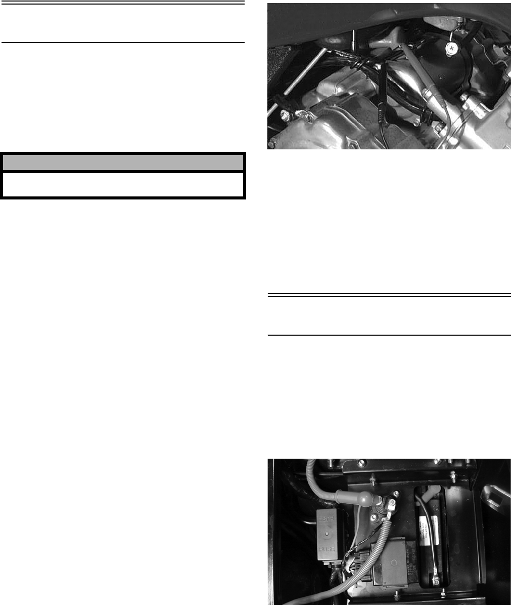
5-12
Starter Motor
NOTE: The starter motor is not a serviceable
component. If the motor is defective, it must be
replaced.
REMOVING
1. Disconnect the battery.
2. Remove the nut securing the positive cable to
the starter; then remove the cable from the
starter.
3. Remove the two machine screws securing the
starter to the crankcase; then remove the starter.
Account for the wiring forms and an O-ring.
INSTALLING
1. Apply a small amount of grease to the O-ring
seal on the starter; then install the starter into the
crankcase. Secure with two machine screws and
wiring forms.
2. Secure the positive cable to the starter with the
nut.
3. Connect the battery.
TESTING VOLTAGE
Perform this test on the starter motor positive termi-
nal. To access the terminal, slide the boot away.
NOTE: The ignition switch must be in the ON
position, and the shift lever (on automatic trans—
mission models) in the NEUTRAL position.
1. Set the meter selector to the DC Voltage posi-
tion.
2. Connect the red tester lead to the starter termi-
nal; then connect the black tester lead to ground.
3. With the starter button depressed, the meter
must show battery voltage and the starter motor
should operate.
AR607D
NOTE: If the meter showed battery voltage but
the starter did not operate or operated slowly,
inspect battery voltage (at the battery), starter
motor condition, and/or ground connections.
NOTE: If the meter showed no battery voltage,
inspect the main fuse, ground connections, starter
motor lead, battery voltage (at the battery), starter
relay, or the neutral start relay.
Starter Relay
1. Remove the operator’s seat; then using the mul-
timeter set to the DC Voltage position, check the
relay as follows.
2. Connect the red tester lead to the positive bat-
tery terminal; then connect the black tester lead
to the starter cable connection on the starter
relay. The meter must show battery voltage.
PR296
NOTE: Make sure that the ignition switch is in
the ON position, transmission in neutral, and park-
ing brake set.
3. Depress the starter button while observing the
multimeter. The multimeter should drop to 0
volts and a “click” should be heard from the
relay.
! CAUTION
Always disconnect the negative battery cable from
the battery first; then disconnect the positive cable.
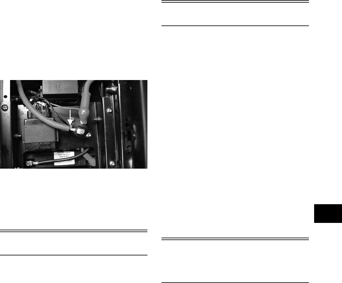
5-13
5
NOTE: If a “click” is heard and any voltage is
indicated by the multimeter, replace the starter
relay. If no “click” is heard and the multimeter con-
tinues to indicate battery voltage, proceed to step
4.
4. Disconnect the two-wire plug from the starter
relay; then connect the red tester lead to the
green wire and the black tester lead to the black
wire.
PR297A
5. Depress the starter button and observe the multi-
meter.
NOTE: If battery voltage is indicated, replace the
starter relay. If no voltage is indicated, proceed to
Neutral Start Relay check.
CDI Unit
The CDI is located beneath the operator’s seat near the
battery.
NOTE: The CDI unit is not a serviceable compo-
nent. If the unit is defective, it must be replaced.
The CDI is rarely the cause for electrical problems;
however, if the CDI is suspected, substitute another
CDI unit to verify the suspected one is defective.
NOTE: Prior to replacing the CDI unit to assure
the CDI unit is defective, it is advisable to perform
a CDI peak voltage test (see Ignition Coil in this
section) and/or perform a continuity test of the wir—
ing harness from the CDI connector to the CDI
unit.
Regulator/Rectifier
The regulator/rectifier is located under the driver’s
seat next to the battery. Try to verify all other charg-
ing system components before the regulator/rectifier
is replaced.
TESTING
1. Start engine and warm up to normal operating
temperatures; then connect a multimeter (set at
the DC Voltage position) to the battery as fol-
lows.
2. Connect the red tester lead to the positive bat-
tery post and the black tester lead to the negative
battery post.
3. Slowly increase RPM. The voltage should
increase with the engine RPM to a maximum of
15.5 DC volts.
NOTE: If voltage rises above 15.5 DC volts, the
regulator is faulty or a battery connection is loose
or corroded. Clean and tighten battery connec-
tions or replace the regulator/rectifier. If voltage
does not rise, check Voltage (Charging Coil — No
Load) in this section. If charging coil voltage is
normal, replace the regulator/rectifier.
Neutral Start/
Start-in-Gear/
2WD Relays
The relays are indentical plug-in type located on the
power distribution module. Relay function can be
checked by switching relay positions. The relays are
interchangeable.
NOTE: The module and wiring harness are not a
serviceable component and must be replaced as
an assembly.

5-14
Headlights
The connectors are the four 2-prong ones secured to
the headlight bulbs (two on each side).
VOLTAGE
NOTE: The low beams are the outside bulbs
(black and white wires) and the high beams are the
inside bulbs (yellow and black wires). Always con-
nect the black tester lead to the black wires. The
ignition switch must be in the ON position.
1. Set the meter selector to the DC Voltage posi-
tion.
2. Set the light switch to the correct position for the
affected light; then connect the black tester lead
to the black wire using a MaxiClip (p/n
0744-041).
3. Connect the red tester lead to the yellow wire
(high beam) or white wire (low beam) using a
MaxiClip (p/n 0744-041). The meter must show
battery voltage.
NOTE: If battery voltage is not shown in any test,
inspect the LIGHTS fuse on the power distribution
module, headlight switch, ignition switch, switch
connectors, or wiring harness.
Taillight-Brakelight
VOLTAGE (Taillight)
NOTE: Perform this test at the socket end of the
taillight-brakelight harness (pigtail). The ignition
switch must be in the ON position and either high
beam or low beam selected on the light switch.
1. Set the meter selector to the DC Voltage posi-
tion.
2. Connect the black tester lead to the black wire;
then connect the red tester lead to the white
wire. The meter should show battery voltage.
3. With the ignition key in the LIGHTS position,
the meter must show battery voltage.
NOTE: If battery voltage is not shown and the
headlights are illuminated, inspect the three-wire
connector in the left-rear canopy tube at the junc-
ture of the canopy tube and lower frame. If battery
voltage is shown on the meter, replace the bulb.
VOLTAGE (Brakelight)
NOTE: Perform this test at the socket end of the
taillight/brakelight harness (pigtail). The ignition
switch must be in the ON position.
1. Set the meter selector to the DC Voltage posi-
tion.
2. Connect the red tester lead to the red/blue wire;
then connect the black tester lead to the black
wire.
3. With the brake applied, the meter must show
battery voltage.
NOTE: If the meter shows no voltage, inspect the
10 amp IGNITION fuse, brakelight switch, wiring
harness, or connectors.
Ignition Timing
The ignition timing cannot be adjusted; however,
verifying ignition timing can aid in troubleshooting
other components. To verify engine timing, use the
following procedure.
1. Attach the engine Timing Light (p/n 0644-197)
to the spark plug high tension lead; then remove
the timing inspection plug from the right-side
crankcase cover.
2. With the Arctic Cat Engine Tachometer (p/n
0644-275) connected, start the engine and run at
the specified RPM.
3. Ignition timing should be 10° BTDC.
4. Install the timing inspection plug.
If ignition timing cannot be verified, the rotor may
be damaged, the key may be sheared, the trigger coil
bracket may be bent or damaged, or the CDI unit
may be faulty.

6-1
6
SECTION 6 — DRIVE SYSTEM
TABLE OF
CONTENTS
Drive System ………………….…………….…………….….. 6-2
General Information…..……………..…………….……….. 6-2
Front Drive Actuator ………..………….…………….…….. 6-3
Front Differential …….………….…………….……………... 6-4
Drive Axles …………………….…………….………….…… 6-17
Rear Gear Case .…………….…………….…………….… 6-22
Hub…………………………….…………….…………….…… 6-23
Hydraulic Brake Caliper…………………….……………. 6-25
Universal Joints …..………….…………….…………….… 6-27

6-2
Drive System
NOTE: Some photographs and illustrations used
in this section are used for clarity purposes only
and are not designed to depict actual conditions.
General Information
All gear cases are tagged beneath a cover bolt. This
tag is marked with a production date code, sequence
code, and a ratio code. All gear cases are 4.0:1 ratio.
The die-cast aluminum housings have been assem-
bled with thread-rolling screws (trilobular). When
assembling with these screws, start the screws care-
fully into the housing; then use the following torque
values.
SPECIFICATIONS
Specific specifications regarding the gear cases
(capacities, lubricant type, etc.) can be found in Sec-
tion 1 of this manual.
SPECIAL TOOLS
A number of special tools must be available to the
technician when servicing the gear case.
NOTE: Special tools are available from the Arctic
Cat Service Parts Department.
TROUBLESHOOTING
If a noise is heard from the gear case area, it can be
difficult to locate and/or diagnose. If the noise is
related to wheel speed, but not to engine RPM, the
problem is probably in the final drive or
engine/transmission bevel gear set. When a problem
is localized, a number of inspections must be made
to pinpoint that problem. The most obvious of the
inspections include CV boots, wheel and hub nut
tightness, wheel bearing damage, gear case lubricant
contamination, low lubricant level, seal leakage, CV
joints, or selector arm.
NOTE: Small metallic particles will collect on the
magnetic drain plug as a normal part of break-in
and will also give a metallic cast to drained lubri-
cant. Contamination would include large particles
or water which gives a “milky” look to the lubri-
cant.
NOTE: Lubricant on a new pinion housing
assembly could be grease. If the front of the gear
case is leaking at the rear drive boot, wipe excess
lubricant from the bottom of the pinion housing;
then operate the vehicle for a period of time.
Inspect the pinion housing area for any signs of
leakage. If lubricant is again on the bottom of the
pinion housing, the seal must be replaced.
Additional troubleshooting could include the fol-
lowing.
• Binding/abrupt motion: CV boot torn (grease loss,
foreign object damage, broken cage); gear lubri-
cant loss or not filled (bearing seizure, broken gear
teeth, seal leakage, bladder or hose leakage,
missing filler/drain plug).
• Noise from drive system: wheel or gear case bear-
ing damage, improper gear backlash, improper
assembly, low or no gear case lubricant.
• Lockup: gear case lubricant loss or not filled, water
contamination causing bearing seizure.
Size New Housing Reassembled
Housing
M6
(Torx T-30 Recess)
1.1-1.3 kg-m
(8-9.5 ft-lb)
0.9-1.2 kg-m
(6.5-9 ft-lb)
M8
(Torx T-40 Recess)
3.5-4.3 kg-m
(25-31 ft-lb)
2.9-3.5 kg-m
(21-25 ft-lb)
Ring Gear Backlash 0.28-0.38 mm (0.011-0.015 in.)
Ring Gear End Play 0.1-0.2 mm (0.004-0.008 in.)
Description p/n
Boot Clamp Pliers 0444-120
Pinion Gear/Shaft Removal Tool 0444-127
Slide Hammer w/CV Joint Attachment 0444-123
CV Joint Attachment (Only) 0444-119
Internal Hex Socket (48 mm) 0444-104
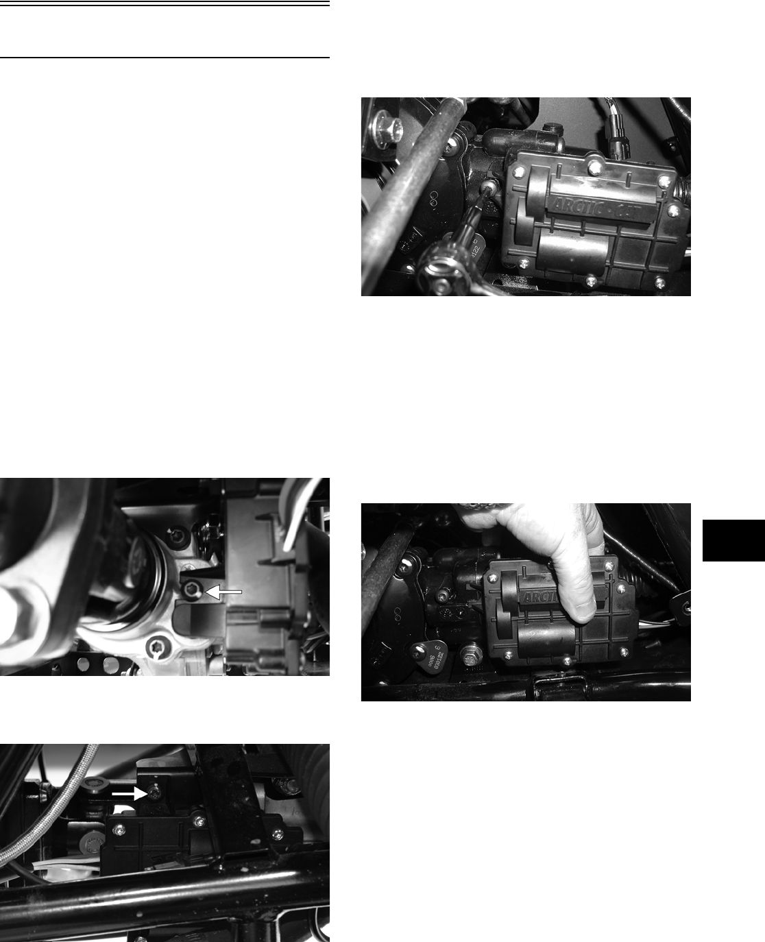
6-3
6
Front Drive Actuator
NOTE: The actuator is not a serviceable compo—
nent. If it is defective, it must be replaced.
NOTE: The actuator will operate only when the
ignition switch is in the ON position.
The front drive actuator is located on the right side
of the front drive input housing. With the engine
stopped and the ignition switch in the ON position, a
momentary “whirring” sound can be heard each
time the front drive selector switch is shifted. If no
sound is heard, see Section 5. If the actuator runs
constantly or makes squealing or grinding sounds,
the actuator must be replaced.
REMOVING
1. Select 4WD on the front drive selector switch;
then disconnect the connector on the actuator
harness.
2. Using a T-30 torx wrench, remove the mounting
cap screw from the driveshaft side of the actua-
tor.
PR189A
3. Remove the mounting cap screw from above the
actuator on the suspension side.
PR190A
4. Loosen but do not remove the mounting cap
screw at the front of the actuator; then slide the
actuator to the rear enough to clear the slotted
mounting tab and the selector shaft. Remove
from the right side.
AG928
INSTALLING
1. Lubricate the O-ring on the actuator; then ensure
that all mounting surfaces are clean and free of
debris.
2. Align the actuator with the selector shaft and
slide it forward onto the shaft taking care to
engage the cap screw in the slot of the front
mounting tab.
AG925
3. While holding the actuator firmly forward,
tighten the front cap screw to hold the actuator
in place; then install but do not tighten the two
remaining cap screws.
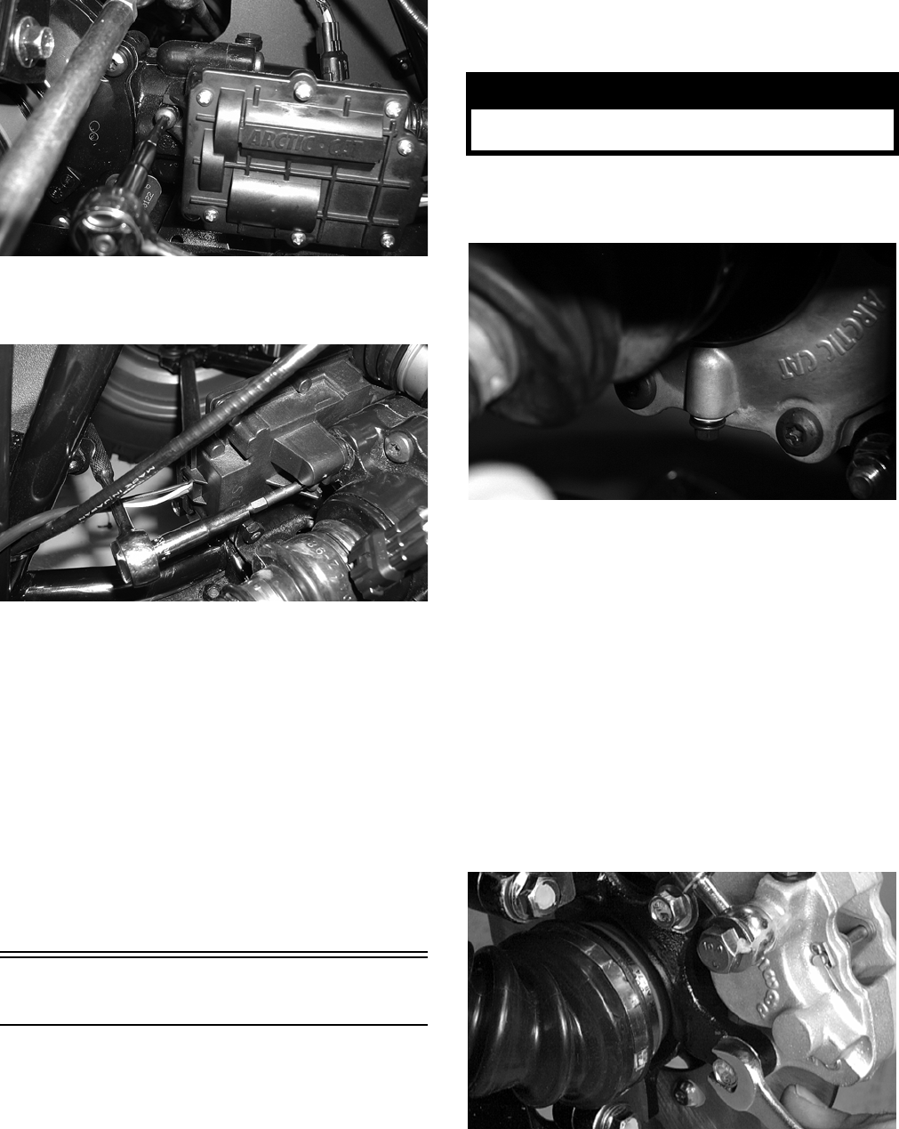
6-4
AG928
4. Loosen the front cap screw; then tighten the cap
screw on the driveshaft side.
AG926
NOTE: It is important to tighten this cap screw
while the others are loose to ensure proper seating
of the actuator.
5. Tighten the remaining cap screws; then connect
the electrical plug to the main harness.
6. Turn the ignition switch to the ON position and
check the operation by shifting the selector
switch several times.
7. Secure the wiring harness to the frame with a
nylon cable tie; then install the inner fender
panel.
Front Differential
REMOVING DIFFERENTIAL
1. Remove the belly panel; then place the vehicle
on jack stands adjusted high enough to allow
working from the underside of the vehicle.
NOTE: The jack stands should be placed under
the main frame to avoid contact with front suspen-
sion components.
2. Remove the drain plug and drain the gear lubri-
cant into a drain pan; then reinstall the plug.
PR022
3. Remove the front wheels.
4. Set the parking brake; then turn the ignition
switch to the ON position and select 4WD on
the 2WD/4WD selector switch.
5. Remove the cotter pin securing the hex nut; then
remove the hex nut.
6. Release the parking brake.
NOTE: It is not necessary to remove the brake
hoses from the calipers for this procedure.
7. Remove the two brake calipers. Account for the
four cap screws; then remove the hubs.
AF894D
8. Disconnect the front drive actuator power con-
nector from the main harness; then disconnect
the differential lock indicator connector from
the differential lock switch located on the
right-side of the differential.
! WARNING
Make sure the vehicle is solidly supported on the
jack stands to avoid injury.
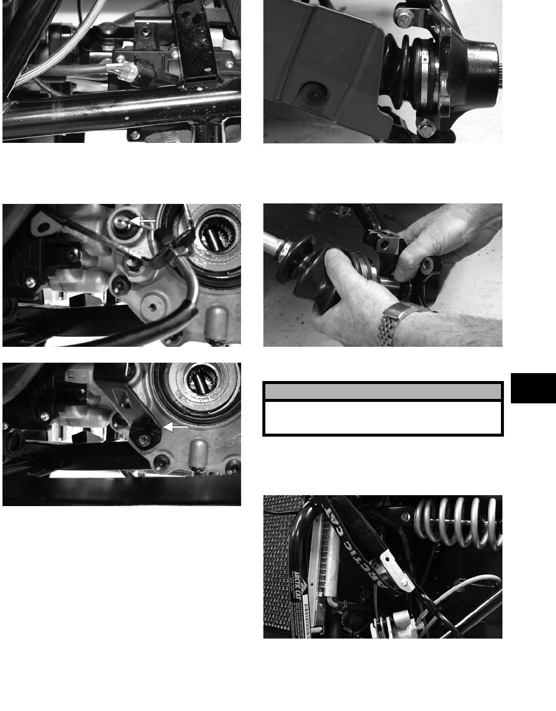
6-5
6
PR191
9. Remove two cap screws securing the differential
lock cable support; then disconnect the differen-
tial lock cable at the differential.
PR194A
PR195A
10. Remove the lower and upper ball joint cap
screws taking care not to strip the threads on the
ball joint shaft; then using a rubber mallet, tap
the end of the axle and free it from the knuckle
assembly.
PR193
11. Pull the steering knuckle away from the axle
taking care not to damage the seals with the axle
end.
PR222
12. Support the axle to not allow it to drop or hang.
13. Remove the lower shock bolts. Account for the
lock nuts; then move the shocks and upper
A-arm up and secure them with a strap.
PR200
14. Scribe match marks on the front input drive
flange and the front drive yoke flange; then
remove three cap screws securing the yoke and
flange. Separate the flanges but do not remove
the driveshaft.
! CAUTION
The axle must be supported. If the axle is allowed
to drop or hang, damage to the inner CV joint
may occur.
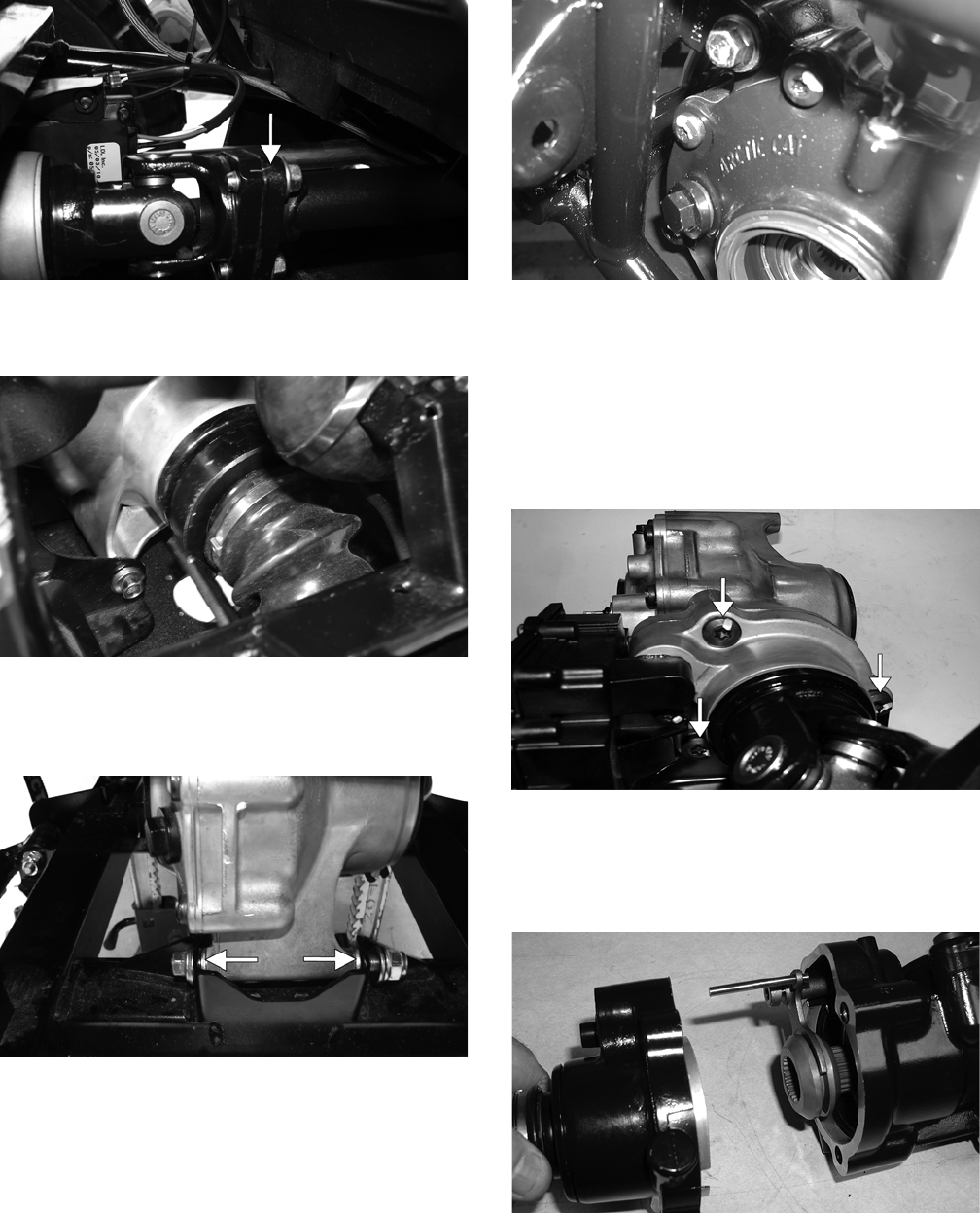
6-6
PR198A
15. Using Slide Hammer w/CV Joint Attachment
(p/n 0444-123), remove the front axles.
PR199
16. Remove the lower differential mounting cap
screw. Account for a lock nut and four washers.
Note the position of the washers for assembling.
PR205A
17. Remove the upper differential mounting cap
screw. Account for a lock nut and two washers.
CD016
18. Free the differential assembly from the frame
mountings; then lower the differential through
the frame.
Disassembling Input Shaft
1. Using a T-40 torx wrench, remove the cap
screws securing the pinion housing.
PR261A
2. Using a rubber mallet, remove the housing.
Account for a gasket. Remove the fork, collar,
and spring. Note the location of all the compo-
nents for assembling purposes.
CD103
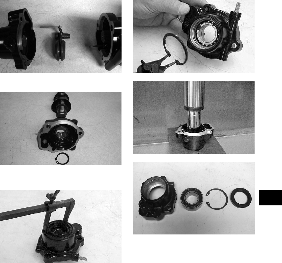
6-7
6
CD106
3. Remove the input shaft from the pinion housing.
CD107
4. Using a seal removal tool, remove the input
shaft seal. Account for a spacer.
AF982
5. Remove the snap ring securing the input shaft
bearing; then place the pinion housing in a press
and remove the bearing.
AF983
AF984
KX219
Assembling Input Shaft
1. Place the pinion housing in a press and install
the input shaft bearing. Secure the bearing with
the existing snap ring making sure the sharp
edge of the snap ring faces to the outside.
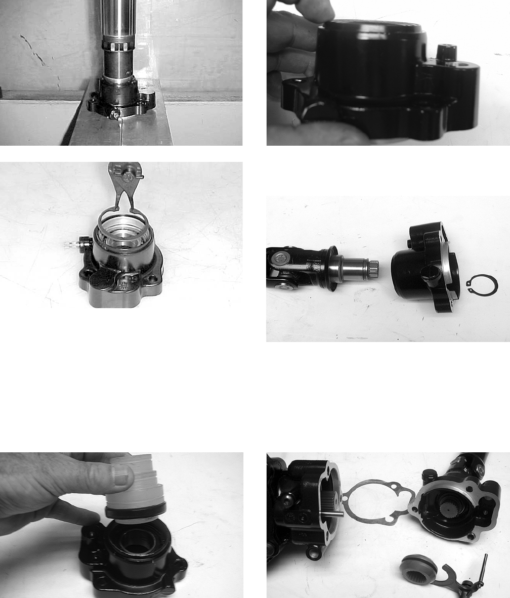
6-8
AF993
AF994
2. Install the input shaft seal making sure it is flush
with the edge of the housing.
3. Lubricate the input shaft splines with High-Per-
formance Grease (p/n 0436-501).
NOTE: Any time drive splines are separated,
clean all splines with parts-cleaning solvent and
dry with compressed air; then lubricate with rec—
ommended grease.
KX221
KX222
4. Install the input shaft into the pinion housing;
then secure in the bearing with a circlip.
KX210A
5. Place the pinion housing with new gasket onto
the gear case housing; then secure with existing
cap screws. Tighten to specifications.
NOTE: If a new gear case housing is being
installed, tighten the cap screws to 3.5-4.3 kg-m
(25-31 ft-lb).
KX209
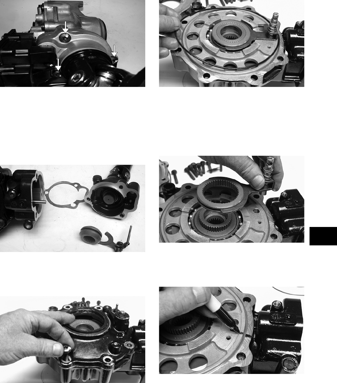
6-9
6
PR261A
Disassembling Pinion Gear
NOTE: This procedure can be performed on a
rear gear case.
1. Using a T-40 torx wrench, remove the cap
screws securing the pinion housing. Account for
the coupler, fork, and spring.
KX209
2. Using a T-40 torx wrench, remove the cap
screws securing the gear case cover. Account for
and make note of the ID tag location for assem-
bling purposes.
KX173
3. Using a plastic mallet, tap lightly to remove the
differential cover. Account for an O-ring.
KX174
NOTE: If the cover is difficult to remove, pry on
the cover in more than one recessed location.
4. Remove the splined coupler, shifter fork, pin,
and spring of the differential lock assembly and
set aside. Note position of parts for assembling
purposes.
KX175
5. Make match marks on the left bearing housing
and differential housing; then remove the plate
and account for a shim. Mark the shim as
left-side.
KX176
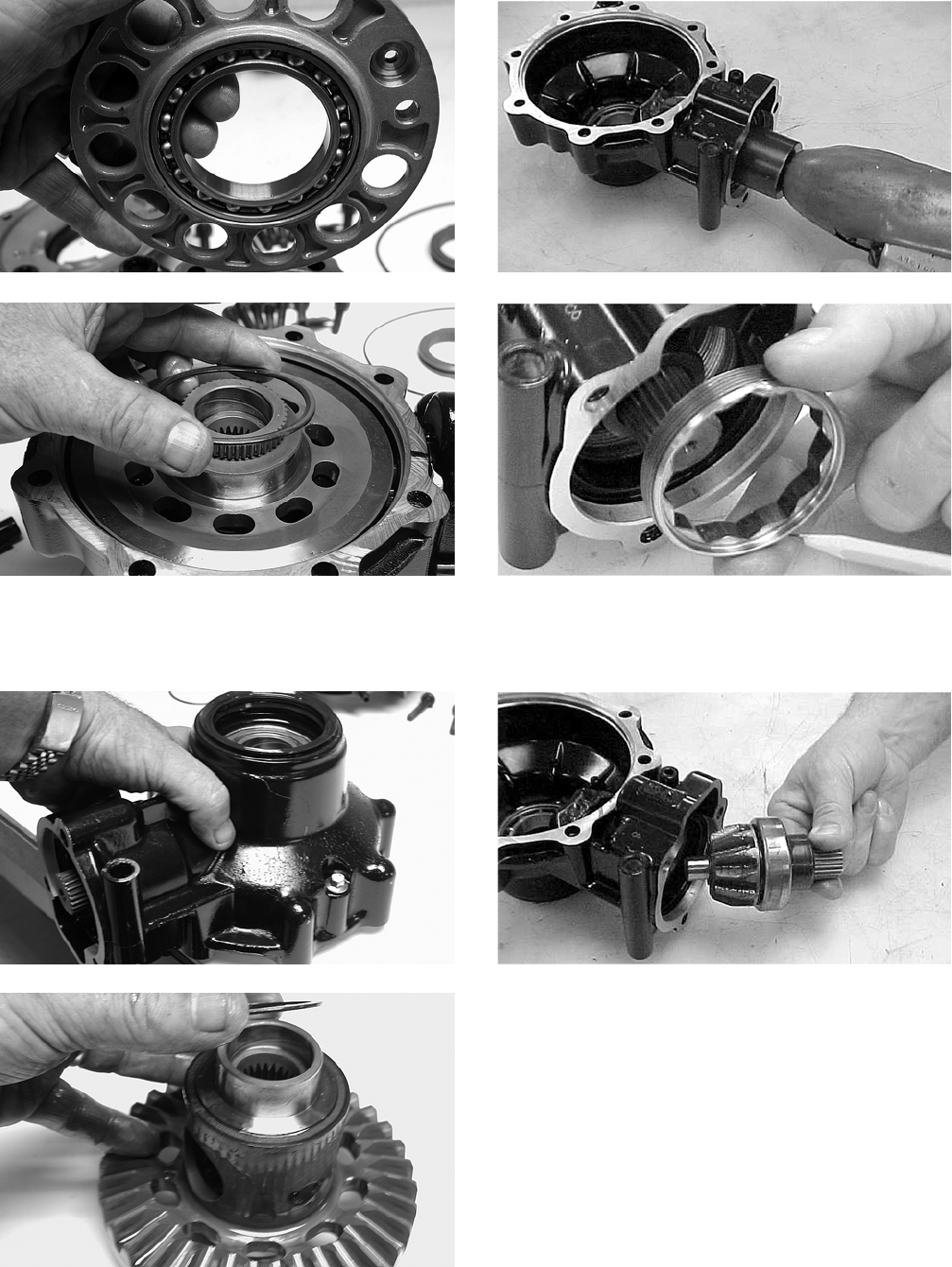
6-10
KX177
KX178
6. Place the differential with the open side down;
then lift the housing off the spider assembly.
Account for shim(s) and mark as right-side.
KX179
KX181
7. Using the 48 mm Internal Hex Socket (p/n
0444-104), remove the lock collar securing the
pinion gear assembly.
CC875
CC876
8. Using the Pinion Gear/Shaft Removal Tool (p/n
0444-127) and a hammer, remove the pinion
gear from the gear case housing.
CC878
9. Secure the pinion gear in a bearing puller; then
remove the pinion bearing using a press.
Account for a collar, a bearing, and a shim.
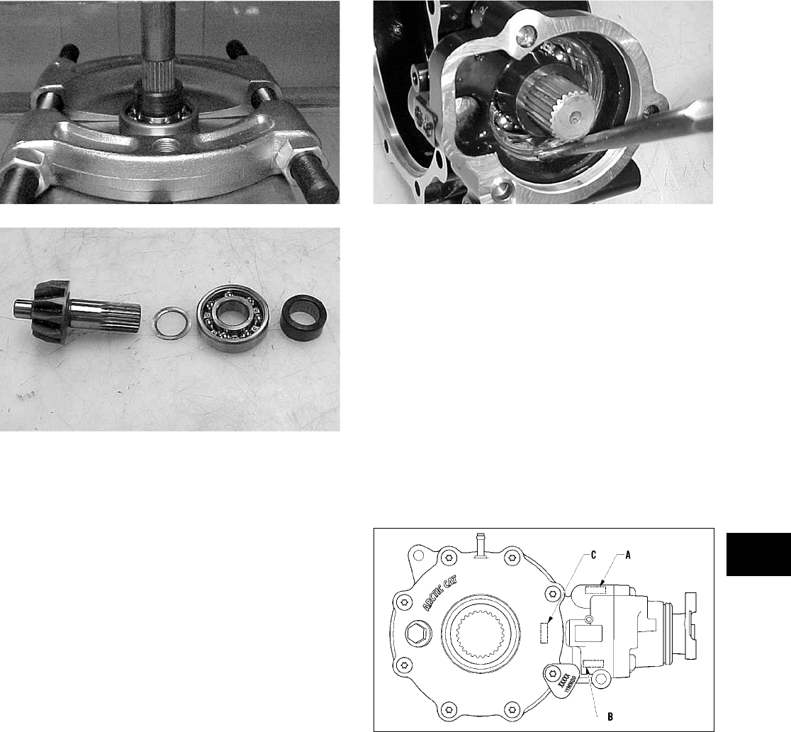
6-11
6
CC879
CC880
NOTE: If gears are being replaced, use the exist-
ing shims. The numbers are scribed onto the
gears: the ring gear has the number on the oppo-
site side of the gears, and the pinion gear has the
number on the end of the pinion gear shaft by the
splines. If no number is present, it should be con-
sidered as being in the 0 category.
NOTE: If the gear case housing is being
replaced, proceed to the following Shimming Pro-
cedure/Shim Selection sub-section.
Shimming Procedure/Shim
Selection
1. Press bearings into bores by outer ring to hard
contact with seat.
2. Note the following shim selections (shims are
nominally 1.5 mm/0.060 in. thick):
A. Pinion Gear Sub-Assembly — add the value
(A) on the gear case housing with 1.5 mm
(0.060 in.); then subtract the value on the
10-tooth pinion gear. This will give you the
proper shim thickness.
B. Install the lock collar and tighten to specifica-
tions; then on final assembling, stake the lock
collar edge approximately 1.5 mm (0.060 in.)
into the lower oil channel.
CC891
NOTE: Do not stake the lock collar until proper
backlash has been verified.
C. Cover Side — add the value (B) on the gear
case housing to the value (C) on the gear case
cover; then add 1.5 mm (0.060 in.). This will
give you the proper shim thickness.
D. Gear Case Side — install a 1.3-1.4 mm
(0.050-0.055 in.) shim and tighten the bolts to
3.5-4.3 kg-m (25-31 ft-lb). Verify backlash to
be within a range of 0.28-0.38 mm
(0.011-0.015 in.) and end-play to be within a
range of 0.10-0.20 mm (0.004-0.008 in.). If
not within specification range, reselect shim
until backlash specification range can be ver-
ified.
738-268A
3. Prior to final assembling, apply molybdenum
disulfide grease to all oil seal lips.
4. Prior to final assembling, prelubricate journal on
pinion assembly with SAE 80W-90 hypoid gear
lubricant prior to pressing assembly into gear
case housing.
Assembling Pinion Gear
1. Place the shim (with the chamfer side toward the
inside) onto the pinion shaft; then install the
bearing onto the pinion shaft. Install the pinion
shaft collar.
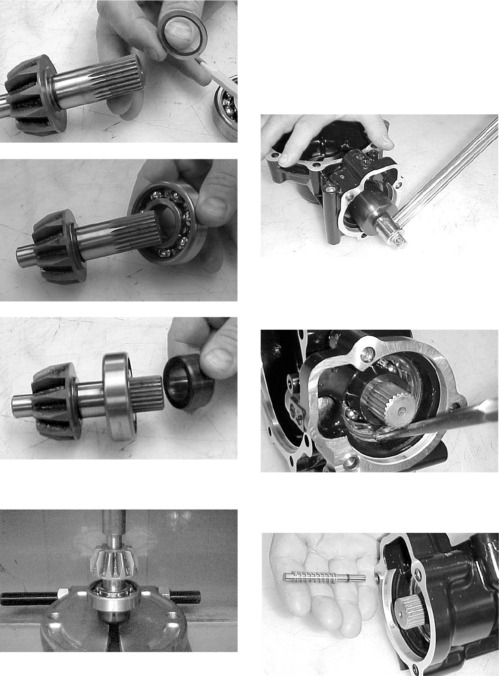
6-12
CC881
CC882
CC883
2. Place the pinion assembly in a bearing puller;
then install the bearing using a press.
CC884
3. Install the pinion gear assembly into the hous-
ing. Using the 48 mm Internal Hex Socket
(p/n 0444-104), secure the pinion gear assembly
with the existing lock collar. Tighten to specifi-
cations.
NOTE: On a front differential, the lock collar has
right-hand threads. On a rear gear case, the lock
collar has left-hand threads.
CC890
4. Place a punch on the edge of the lock collar in
the oil gallery area; then using a hammer, stake
the lock collar to ensure that the collar will
remain securely tightened.
CC891
5. Install the shift fork shaft w/spring into the gear
housing making sure the shaft O-ring is posi-
tioned to the inside.
CC892
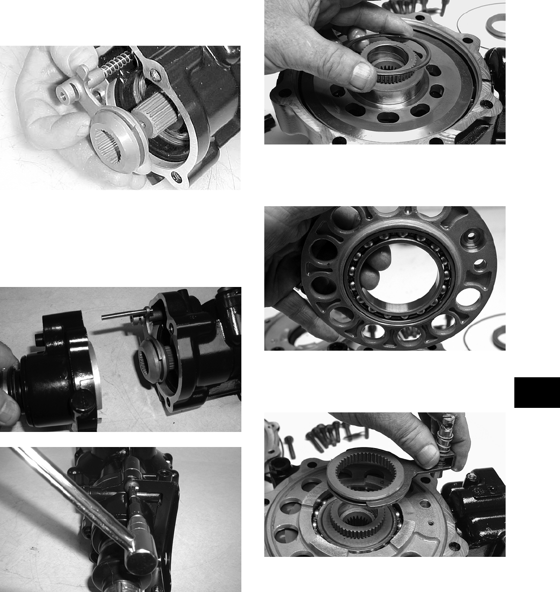
6-13
6
6. Install the shift fork assembly making sure the
fork leg is facing upward. Apply a small amount
of oil to the gasket; then install the gasket.
CC893
7. Place the input shaft assembly onto the gear
housing; then secure with the existing cap
screws. Tighten to specifications.
NOTE: If a new gear housing is being installed,
tighten the cap screws to 3.5-4.3 kg-m (25-31 ft-lb).
CD103
CD110
8. Install the proper shim onto the ring gear spider
assembly making sure the chamfer side of the
shim is facing toward the ring gear. Install the
ring gear in the housing; then install the outside
shim with the chamfer side of the shim toward
the ring gear.
NOTE: The spider and ring gear assembly must
be replaced as a complete unit.
KX178
9. Install the left bearing housing aligning the
match mark to the mark on the differential hous-
ing.
KX177
10. Install the differential lock assembly into the
bearing housing; then place the O-ring on the
gear case housing.
KX175
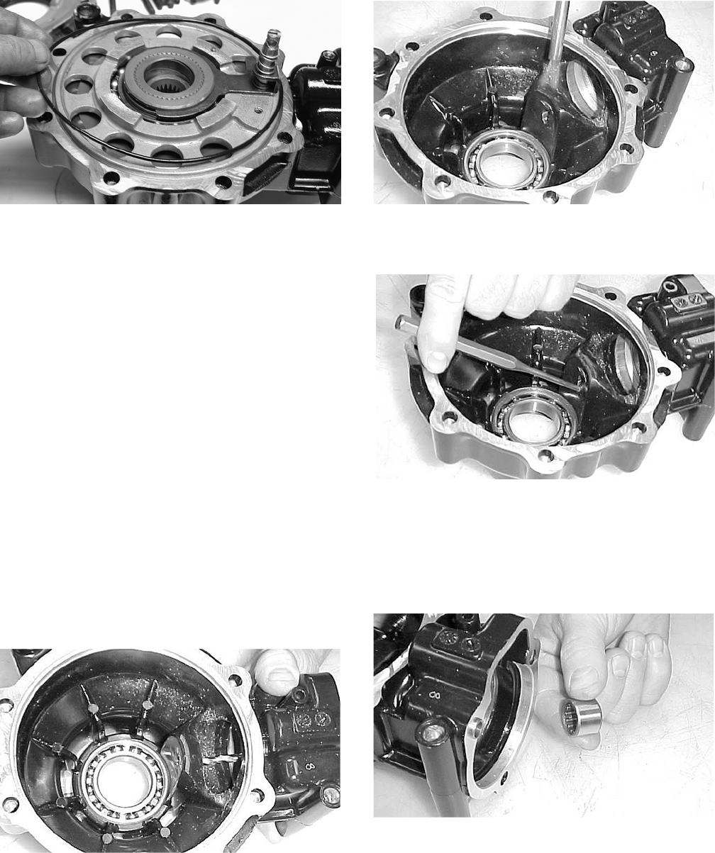
6-14
KX174
11. Making sure the O-ring is properly positioned
on the gear case housing, install the housing
with existing hardware. Account for the ID tag.
Tighten the cap screws to specifications.
NOTE: Grease can be applied to the O-ring for
ease of assembling.
NOTE: If a new gear case housing is being
installed, tighten the cap screws to 3.5-4.3 kg-m
(25-31 ft-lb).
Removing Needle Bearing
NOTE: Removing the needle bearing is rarely
necessary. Avoid removing the needle bearing
unless the bearing is clearly damaged.
NOTE: This procedure can be performed on a
rear gear case.
1. Place a 6.35 mm (1/4 in.) drill bit on the inside
surface of the needle bearing (against the bottom
side); then drill through the pinion shaft needle
bearing housing.
CC885
2. Using a propane torch, heat the area surrounding
the needle bearing to soften the Loctite.
CC886
3. Using a flat-nosed punch, drive the bearing out
of the housing.
CC887
Installing Needle Bearing
1. Apply red Loctite #271 to the outside of a new
bearing; then place the new bearing into the
housing.
CC888
2. Using a suitable driver, install the needle bear-
ing into the gear case housing making sure the
bearing is seated.
NOTE: Do not push the bearing too far into the
housing.
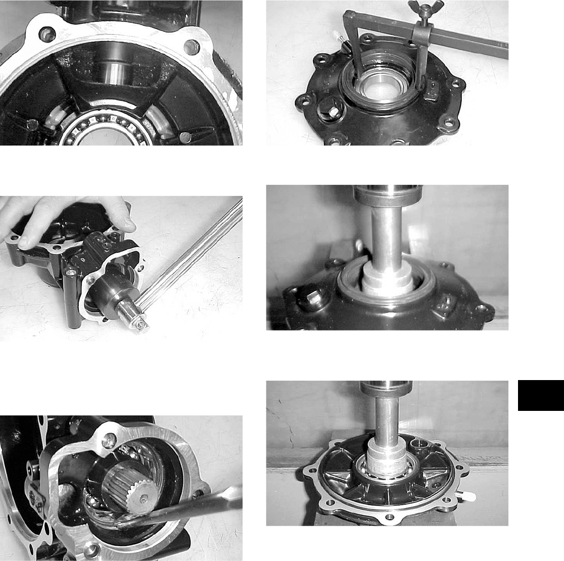
6-15
6
CC889
3. Install the pinion shaft and secure with the exist-
ing 48 mm lock collar. Tighten to specifications.
CC890
4. Place a punch on the edge of the lock collar in
the oil gallery area; then using a hammer, stake
the lock collar to ensure that the collar will
remain securely tightened.
CC891
5. Install the pinion housing.
Removing/Installing Axle Seal
NOTE: This procedure can be performed on a
rear gear case.
1. Remove the seal using a seal removal tool.
CC899
2. Using a press, remove the bearing.
CC900
3. Using a press, install the new bearing into the
housing.
CC901
NOTE: Prior to installing the seal, apply grease
to the seal outside diameter.
4. Install the seal into the housing pressing evenly
on the outside edge until the seal is seated.
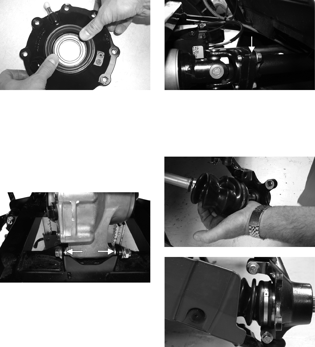
6-16
CD018
5. Repeat steps 1-4 for the opposite side.
INSTALLING DIFFERENTIAL
1. Place the differential assembly into position in
the frame; then install the top mounting
through-bolt, two washers, and lock nut. Do not
tighten at this time.
2. Install the lower front mounting through-bolt,
washers, spacers, and lock nut. Note the correct
location for the spacer washers.
PR205A
3. Tighten the nuts to specifications.
4. Pour 275 ml (9.3 fl oz) of SAE 80W-90 hypoid
lubricant into the differential and install the
filler plug. Tighten to specifications.
5. Align the scribed match marks on the front input
drive flange and the front drive yoke flange;
then secure with the three cap screws tightened
to specifications.
PR198A
6. Install the front axles (see Drive Axles in this
section).
7. Install the knuckle assemblies onto the axles and
ball joints; then secure with four cap screws tak-
ing care not to damage the threads when install-
ing. Tighten to specifications.
PR201
PR193
8. Secure the lower shock eyelets with cap screws
and lock nuts. Tighten to specifications.
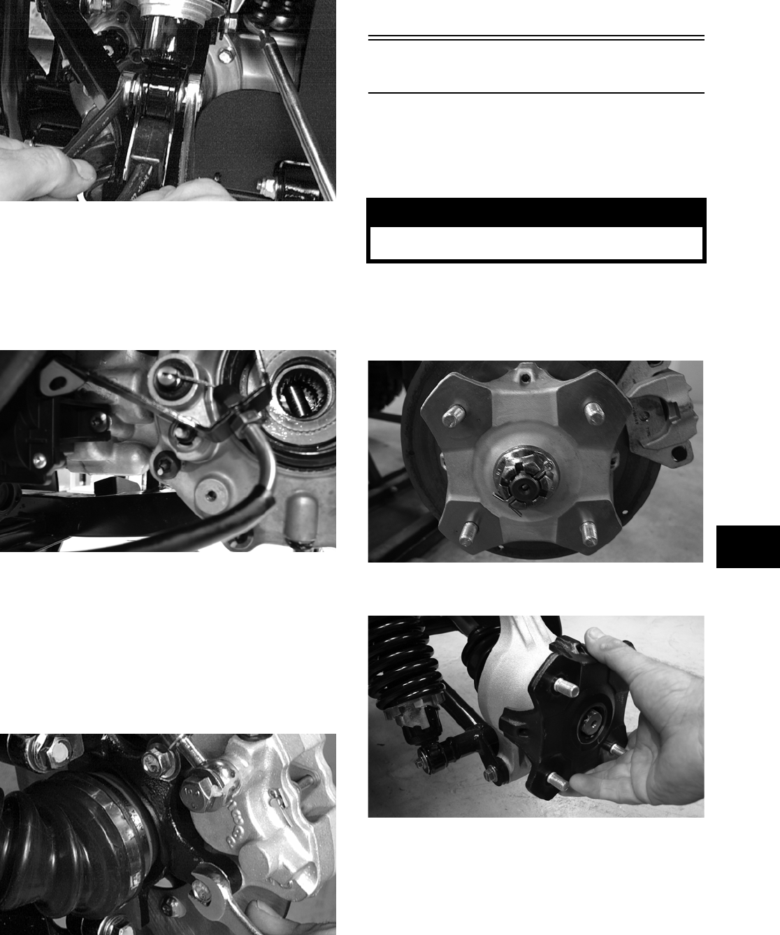
6-17
6
AF897D
9. Install the brake calipers. Secure with the cap
screws tightened to specifications.
10. Install the differential lock cable support making
sure to connect the cable end in the actuator
plunger; then secure with two torx-head cap
screws and tighten to specifications.
PR194
11. Connect the front drive actuator connector to the
main harness and the differential lock indicator
connector to the differential; then secure the
wires to the frame with nylon ties.
12. Apply a light coat of multi-purpose grease to the
hub splines; then install the hubs and nuts.
Tighten to specifications; then install new cotter
pins.
AF894D
13. Install the wheels and tighten to specifications.
14. Remove the vehicle from the support stand.
15. Install the belly panel.
Drive Axles
REMOVING REAR DRIVE AXLE
1. Secure the vehicle on a support stand to elevate
the wheels.
2. Set the parking brake; then remove the wheels.
3. Remove the cotter pins securing the hex nuts;
then remove the hex nuts.
KX041
4. Slide the hub out of the knuckle and set aside.
PR221
5. Remove the cap screw and lock nut securing the
knuckle to the upper A-arm. Discard the lock
nut.
! WARNING
Make sure the vehicle is solidly supported on the
support stand to avoid injury.
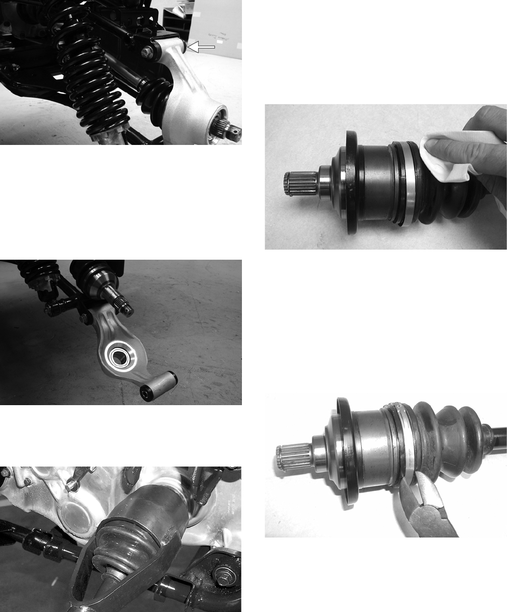
6-18
PR220A
NOTE: Never reuse a lock nut. Once a lock nut
has been removed, it must be replaced with a new
lock nut.
6. While holding the drive axle stationary, pull the
top of the knuckle out and down until it is free of
the drive axle.
PR218
7. Place a drain pan under the vehicle to contain
any oil leakage; then using a slide hammer,
remove the drive axle.
AF935
REMOVING FRONT DRIVE AXLE
NOTE: For removing a front drive axle, see Front
Differential in this section.
CLEANING AND INSPECTING
NOTE: Always clean and inspect the drive axle
components to determine if any service or replace-
ment is necessary.
1. Using a clean towel, wipe away any oil or
grease from the axle components.
CD019
2. Inspect boots for any tears, cracks, or deteriora-
tion.
NOTE: If a boot is damaged in any way, it must
be replaced with a boot kit.
DISASSEMBLING AXLES
1. Using a side-cutters (or suitable substitute),
remove the large clamp from the boot.
CD020
2. Wipe away excess grease to access the retaining
ring. Using an awl or circlip pliers, remove the
circlip.
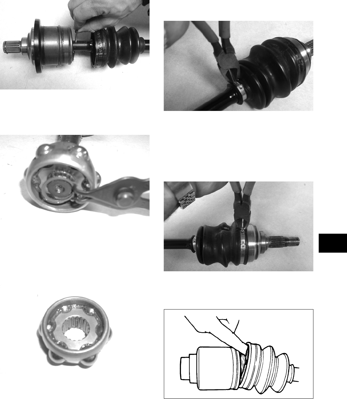
6-19
6
CD021
3. Using a snap ring pliers, remove the circlip
securing the bearing ring to the shaft. Note the
direction of the bearing for assembling pur-
poses.
CD023
4. Note the difference inside each bearing ring end
for assembling purposes; then remove the bear-
ing ring.
NOTE: The recess of the bearing must face
toward the housing.
CD022
5. Inspect the splines of the shaft, the bearing ring,
and the housing for damage.
NOTE: If any damage is apparent to the splines,
the bearing ring, and/or the housing, the drive axle
must be replaced as an assembly.
6. Using a side-cutters (or suitable substitute),
remove the small clamp from the shaft.
CD752
NOTE: At this point if the outside boot is dam-
aged, continue with step 7.
7. Using a side-cutters (or suitable substitute),
remove both outside boot clamps from the shaft.
Note the position of the different-sized clamps
for assembling purposes.
CD751
8. Apply 40 grams (1/3 of contents) of grease from
the Grease Pack (p/n 0441-173) into the knuck-
les and the new outside boot.
ATV-1052
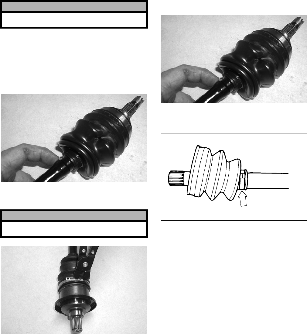
6-20
NOTE: Grease Pack (p/n 0441-173) contains 120
grams of grease. The inside joint (double-offset)
requires approximately 70-90 grams of grease and
the outside (bell-type) requires approximately
35-55 grams. When replacing boots, use 2/3 of the
pack for inside boots and 1/3 of the pack for out-
side boots.
9. Slide the new outside boot onto the shaft with
the new clamps positioned as shown. Note the
different-sized clamps from removal.
NOTE: The boot is positioned correctly when the
small end of the boot seats down into the recessed
groove.
CD754
10. Using Boot Clamp Pliers (p/n 0444-120), secure
both outside boot clamps.
CD024
ASSEMBLING AXLES
1. Install the inner boot with the small clamp mak-
ing sure the ends of the clamp are positioned
correctly.
NOTE: The boot is positioned correctly when the
small end of the boot seats down into the recessed
groove.
CD754
2. Using the boot clamp pliers, secure the small
clamp of the inner boot.
ATV-1048
3. Apply 80 grams (2/3 of contents) of grease from
the pack into the bearing housing.
4. Install the bearing onto the shaft making sure the
recess of the bearing is facing the housing.
! CAUTION
Do no over-fill the joint as boot damage may occur
resulting in joint failure.
! CAUTION
It is important that the clamps are positioned cor-
rectly or they may loosen when in motion.
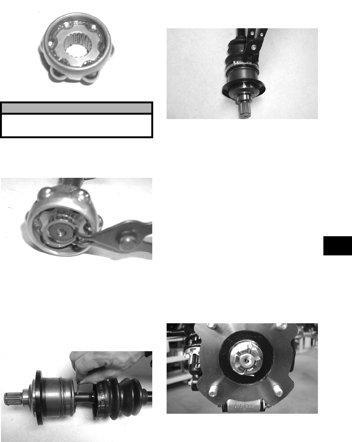
6-21
6
CD022
5. Secure the bearing ring with the circlip making
sure the sharp side of the circlip faces away
from the boot.
CD023
6. Making sure the marks made during disassem-
bling align, slide the housing over the bearing
ring; then completely seat the bearing ring into
the housing and install the circlip.
NOTE: Pull the bearing ring out of the housing
until it contacts the circlip; then slide the ring in
half way. This will purge air from the housing and
ensure the bearing is packed properly.
CD021
7. Slide the boot over the housing; then using the
boot clamp pliers, secure the boot with the
clamp.
CD024
8. Inspect the axle components for correct posi-
tioning of the four clamps. Also, inspect the
boots for being correctly positioned on the shaft.
INSTALLING REAR DRIVE AXLE
1. Slide the drive axle into place in the gear case.
NOTE: To assure proper seating of the axle, give
it a light pull; the axle should remain “clipped” in
place.
2. Swing the knuckle up and onto the drive axle;
then place the knuckle into place in the upper
A-arm. Secure the knuckle to the A-arm with a
cap screw and a new lock nut. Tighten to speci-
fications.
3. Place the hub into position on the axle followed
by a hex nut. Tighten the hex nut finger-tight at
this time.
4. Tighten the hub hex nut (from step 3) to specifi-
cations; then install and spread a new cotter pin
making sure each side of the pin is flush to the
hub nut.
CD027
5. Install the wheel. Tighten to specifications.
6. Remove the vehicle from the support stand and
release the parking brake.
! CAUTION
The bearing ring must go onto the shaft with the
side without splines facing toward the small clamp
of the inner boot or severe damage will result.
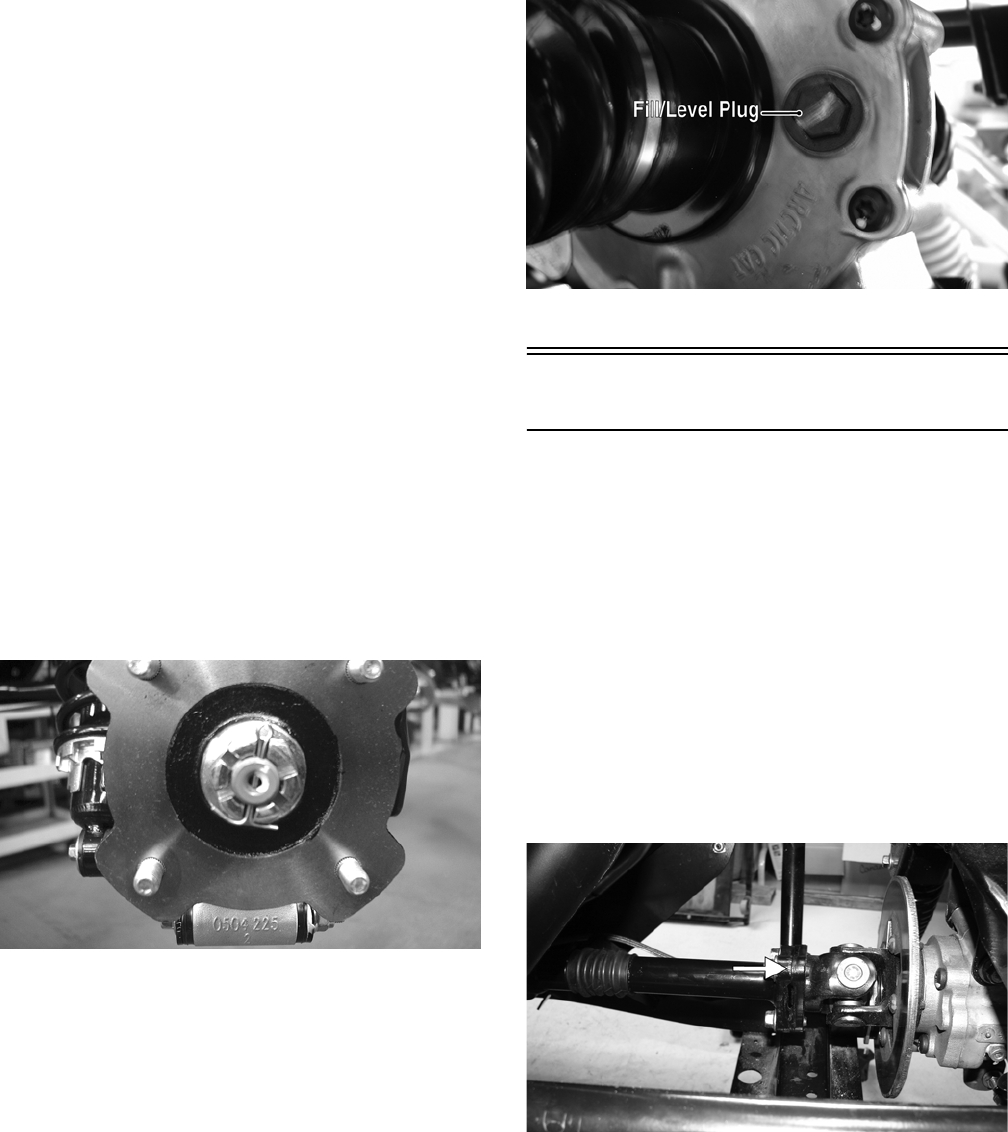
6-22
INSTALLING FRONT DRIVE AXLE
1. Position the drive axle in the gear case and steer-
ing knuckle; then insert the ball joints into the
steering knuckles. Secure with cap screws tight-
ened to specifications.
2. Secure the lower shock eyelet to the A-arm with
a cap screw and a new lock nut. Tighten to spec-
ifications.
3. Slide the hub w/brake disc into position in the
steering knuckle followed by a hex nut. Tighten
finger-tight at this time.
4. Install the brake caliper on the steering knuckle.
Tighten to specifications.
5. Set the parking brake; then turn the ignition
switch to the ON position, select 4WD on the
2WD/4WD drive selector switch, and engage
the differential lock. Turn the ignition switch to
the OFF position.
6. Tighten the hub hex nut (from step 3) to specifi-
cations; then install and spread a new cotter pin
making sure each side of the pin is flush to the
hub nut.
CD027
7. Install the wheel and tighten to specifications.
8. Remove the vehicle from the support stand.
9. Check the front differential oil level and add oil
as necessary.
PR046A
Rear Gear Case
REMOVING
NOTE: Release the cargo box latch and allow the
cargo box to tilt back; then remove the cargo box
lift support by disengaging the ball sockets from
the ball studs and tilt the cargo box all the way
back.
1. Remove both of the rear drive axles (see Drive
Axles in this section).
2. Scribe a match mark on the rear input drive
flange and the rear input yoke flange; then
remove three cap screws securing the flanges
together.
PR211A
3. Remove the drive-line brake caliper.
4. Remove the two cap screws and lock nuts secur-
ing the rear gear case to the frame; then remove
the gear case through the upper left-side of the
frame and lift out the top.
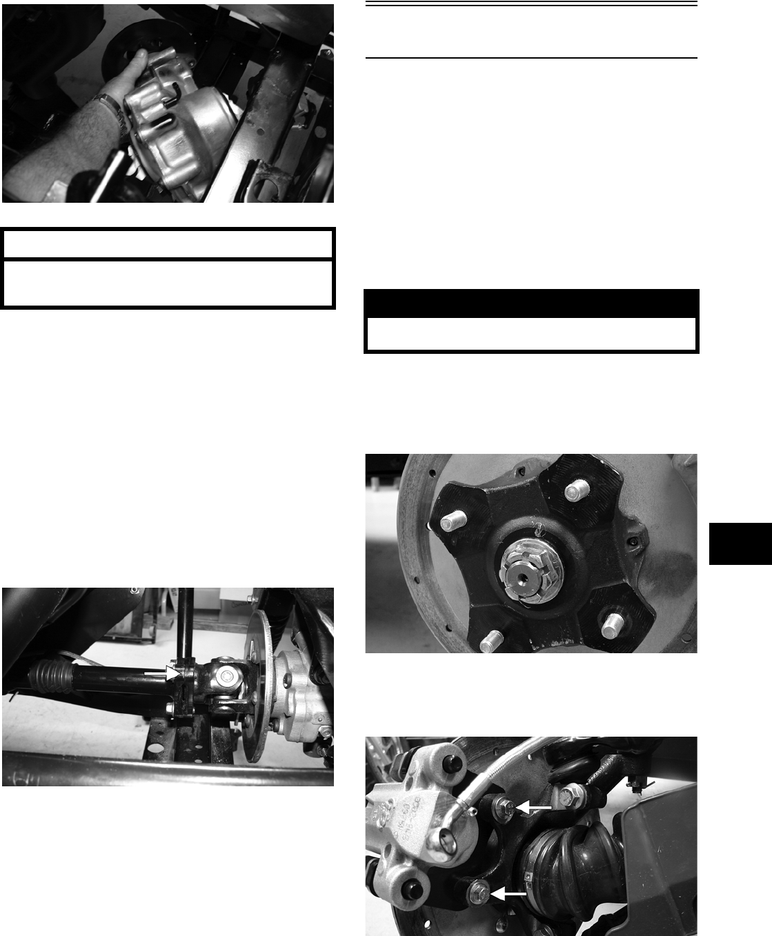
6-23
6
PR207
INSTALLING
1. Slide the gear case into position down through
the upper-left side of the frame; then secure it to
the frame with cap screws and lock nuts.
Tighten to specifications.
NOTE: If a new gear case is being installed,
tighten the cap screws to 5.1-6.3 kg-m (37-45.5
ft-lb).
2. Align the scribed match marks on the rear input
drive coupler flange and the rear input yoke
flange; then install three cap screws and tighten
to specifications.
PR211A
3. Install the rear drive axles (see Drive Axles in
this section).
4. Install the drive-line brake caliper and tighten
the mounting cap screws to specifications; then
adjust the parking brake (see Parking Brake in
Section 2).
Hub
REMOVING
1. Secure the vehicle on a support stand to elevate
the wheel; then remove the wheel.
NOTE: Removing or tightening of the hub nuts
requires that the axles be locked. To lock the rear
axle, set the parking brake. To lock the front axle,
turn the ignition switch to ON, select 4WD on the
2WD/4WD drive selector switch, and engage the
differential lock; then set the parking brake and
turn the ignition switch to OFF.
2. Remove the cotter pin from the axle.
NOTE: During assembly, new cotter pins should
be installed.
PR257
3. Remove the flange nut securing the hub.
4. Remove the brake caliper (front only).
PR243A
5. Remove the hub assembly.
AT THIS POINT
For servicing the input shaft, pinion gear, needle
bearing, and axle seal, see Front Differential in
this section. ! WARNING
Make sure the vehicle is solidly supported on the
support stand to avoid injury.
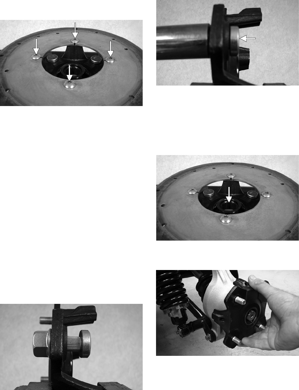
6-24
6. Remove the four cap screws securing the brake
disc (front hub only).
PR254A
CLEANING AND INSPECTING
NOTE: Whenever a part is worn excessively,
cracked, or damaged in any way, replacement is
necessary.
1. Clean all hub components.
2. Inspect all threads for stripping or damage.
3. Inspect the brake disc (if applicable) for cracks
or warping.
4. Inspect the hub for pits, cracks, loose studs, or
spline wear.
REPLACING WHEEL STUDS
To replace wheel studs, use the following procedure.
1. Secure the hub in a suitable holding fixture and
remove the brake disc (if applicable).
2. Drive the damaged stud out of the hub; then
place the new stud into the hub and thread on an
appropriate flange nut.
PR250
3. Using a socket and ratchet handle, tighten the
nut until the stud is fully drawn into the hub.
PR252A
INSTALLING
1. Secure the brake disc (if applicable) to the hub
with the four cap screws coated with red Loctite
#271. Tighten to specifications.
2. Apply grease to the splines in the hub.
PR254B
3. Install the hub assembly onto the axle; then set
the parking brake.
PR221
4. Secure the hub assembly with the nut. Tighten to
specifications; then secure with a new cotter pin.
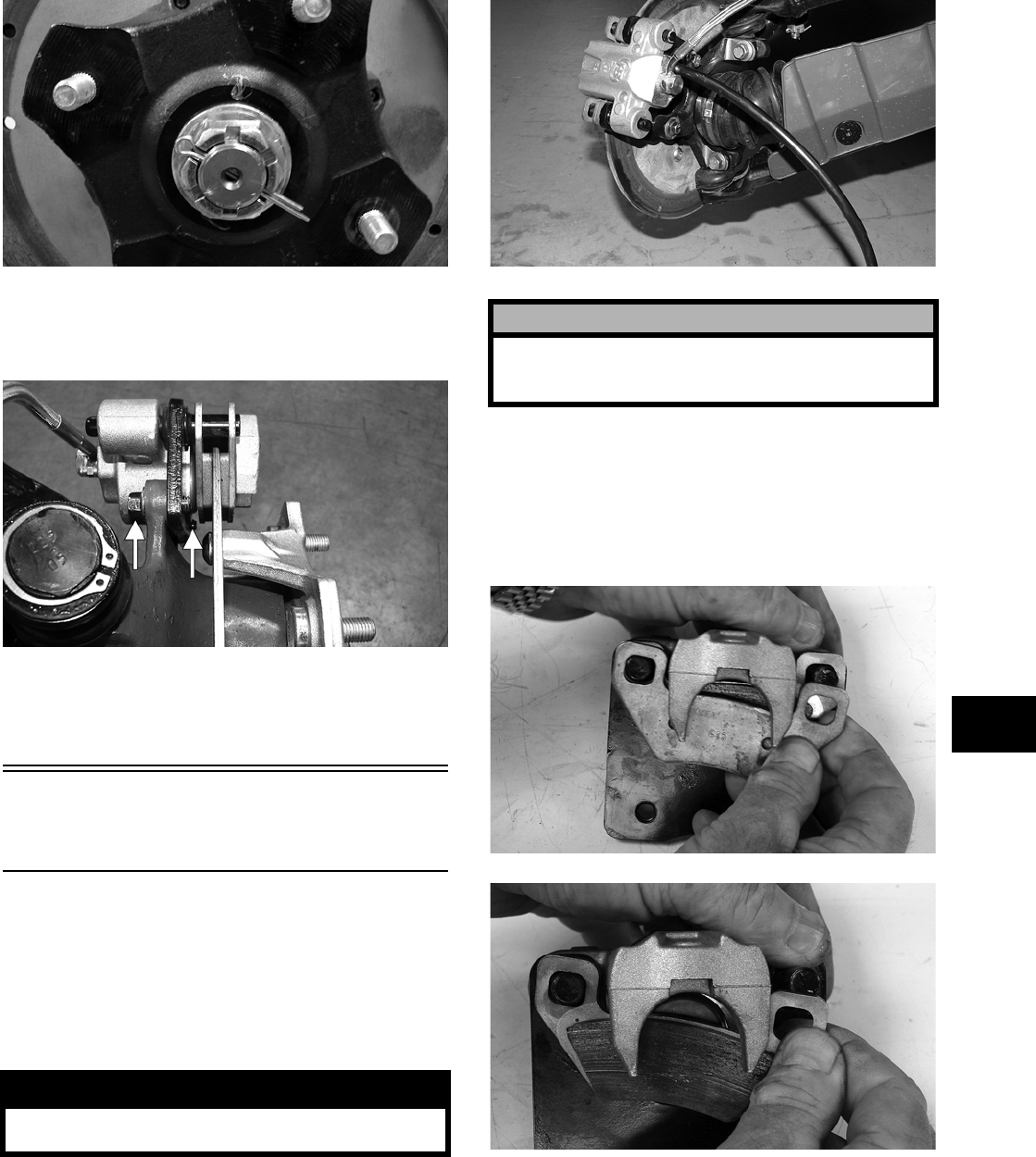
6-25
6
PR258
5. For front hubs, secure the brake calipers to the
knuckle with two cap screws tightened to speci-
fications.
PR377B
6. Install the wheel and tighten to specifications.
7. Remove the vehicle from the support stand.
Hydraulic
Brake Caliper
NOTE: The brake caliper is a non-serviceable
component; it must be replaced as an assembly.
REMOVING/DISASSEMBLING
1. Secure the vehicle on a support stand to elevate
the wheel; then remove the wheel.
2. Drain the brake fluid from the caliper, hose, and
master cylinder.
PR235
3. Remove the brake hose from the caliper; then
remove the caliper and plug the brake fluid port.
4. Compress the caliper holder against the caliper
and remove the outer brake pad; then remove
the inner brake pad.
PR237
PR238
5. Remove the caliper holder from the caliper and
account for the brake caliper O-ring. Do not
remove the piston from the caliper.
! WARNING
Make sure the vehicle is solidly supported on the
support stand to avoid injury.
! CAUTION
Brake fluid is highly corrosive. Do not spill brake
fluid on any surface of the vehicle and do not reuse
brake fluid.
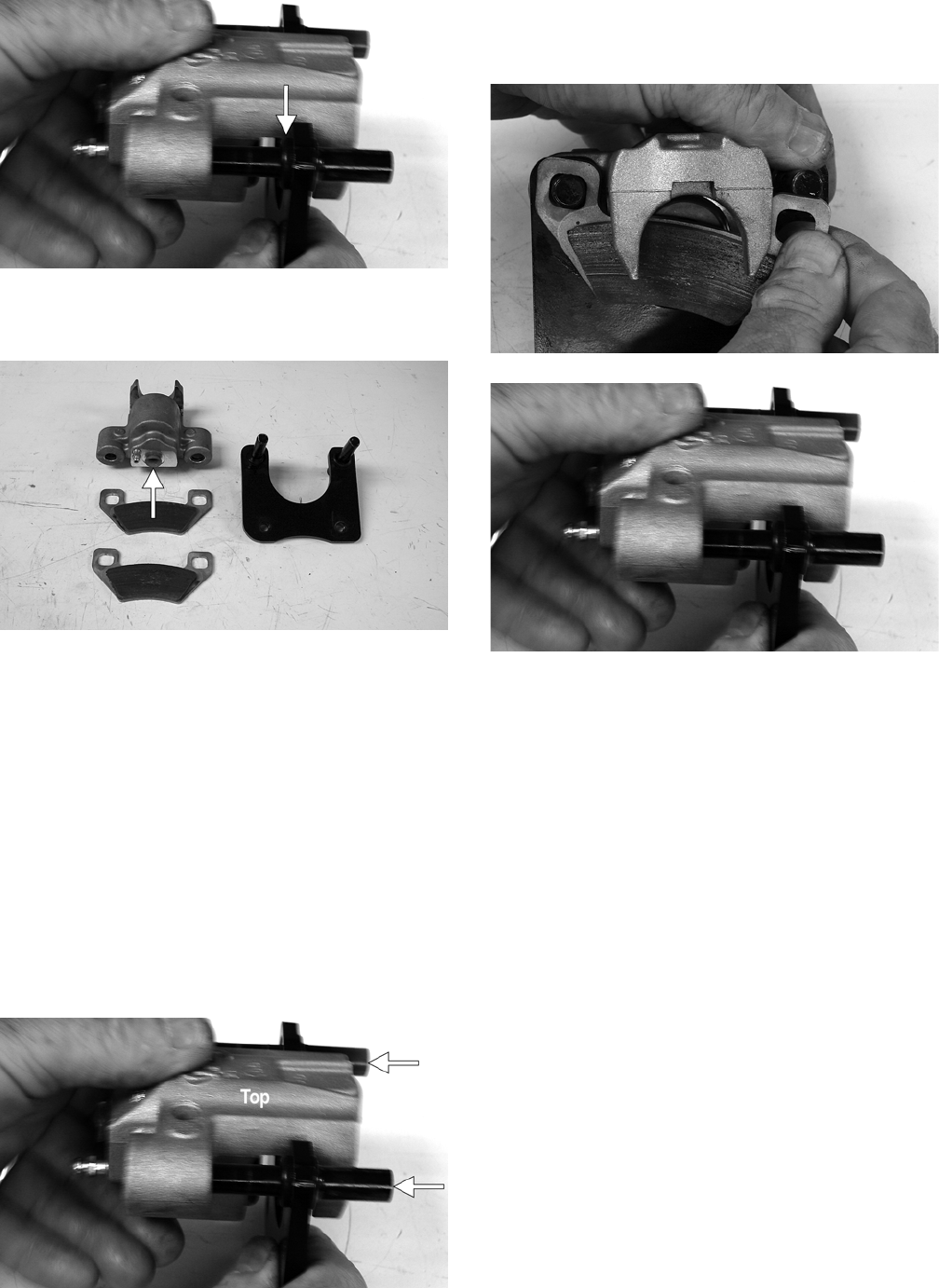
6-26
PR239B
6. Plug the fluid port with a suitable plug to pre-
vent contamination during cleaning.
PR240A
CLEANING AND INSPECTING
1. Clean all caliper components (except the brake
pads) with parts-cleaning solvent.
2. Inspect the brake pads for damage and excessive
wear.
NOTE: For measuring brake pads, see Section 2.
ASSEMBLING/INSTALLING
1. Install the caliper onto the caliper holder making
sure the caliper is correctly oriented on the
holder.
PR239C
2. Compress the caliper holder toward the caliper
and install the inner brake pad; then install the
outer pad.
PR238
PR239
3. Place the brake caliper assembly into position
and secure with the cap screws. Tighten the cali-
per to specifications.
4. Place a new crush washer on each side of the
brake hose fitting and install it on the caliper.
Tighten to specifications.
5. Fill the reservoir; then bleed the brake system
(see Section 2).
6. Install the wheel. Tighten to specifications.
7. Remove the vehicle from the support stand and
verify brake operation.
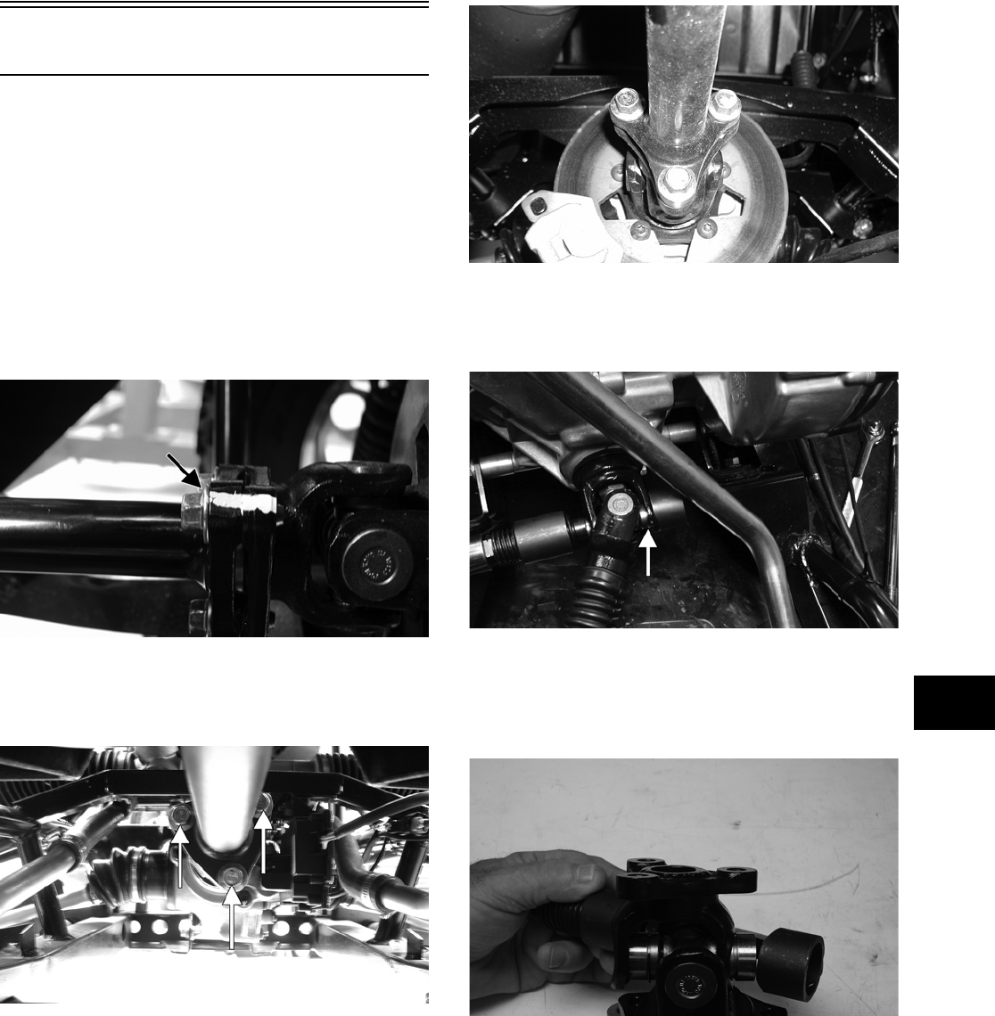
6-27
6
Universal Joints
REMOVING
NOTE: The four universal joints can be accessed
by removing the belly panel. To remove the belly
panel, see Belly Panel in Section 8.
1. Support the vehicle on suitable jack stands ele-
vated high enough to allow working from the
underside of the vehicle.
2. To aid in installing, match mark drive-line com-
ponents prior to removing.
PR152A
3. Remove the cap screws securing the propeller
shaft flange to the yoke flange on the appropri-
ate drive-line; then remove the propeller shaft.
PR120A
PR121
4. Install U-Joint Separator Tool (p/n 0444-128) on
the universal joint fixed yoke; then remove the
bearing cup retainers.
PR354A
5. Using a suitable socket and ratchet handle,
rotate the jackscrew to push the bearing cup out
of the yoke; then remove the tool and the bear-
ing cup.
PR359
6. Install the separator tool on the opposite side of
the yoke to push the second bearing cup from
the yoke; then remove the tool and separate the
universal joint.
7. Secure the separator tool in a vise and repeat
steps 4-6 to remove the bearing cups from the
movable yoke.
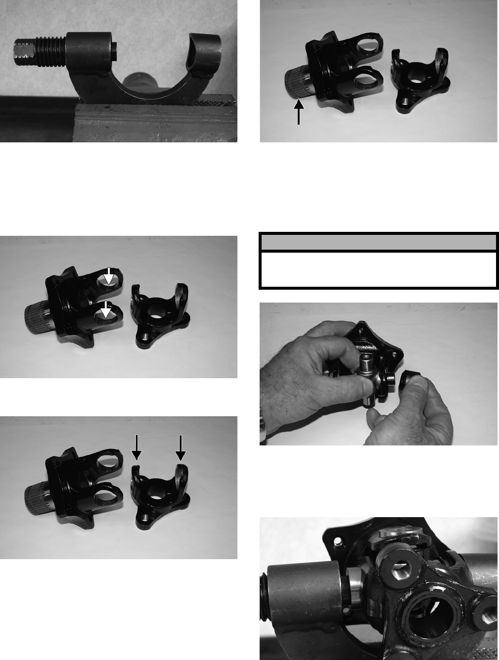
6-28
PR375
INSPECTING
1. Inspect the yoke bores for damage or signs of
bearing cup looseness. If bearing cups are loose,
the yoke must be replaced.
PR367B
2. Check that yoke legs are parallel.
PR367A
3. Check splines and flanges for excessive wear,
thread damage, or warpage.
PR367C
INSTALLING
1. Remove the bearing cups from the universal
cross; then insert the cross into the yoke and
install one bearing cup on the cross.
PR368
2. Secure U-Joint Separator Tool (p/n 0444-128) in
a vise; then place the yoke, cross, and bearing
cup into position and press the cup into the
yoke.
PR374
3. Install the retainer in the bearing cup; then
remove the yoke from the separator tool.
! CAUTION
Care must be taken when installing bearing cups
that the needle bearings stay in place or severe
damage to the universal joint will occur.
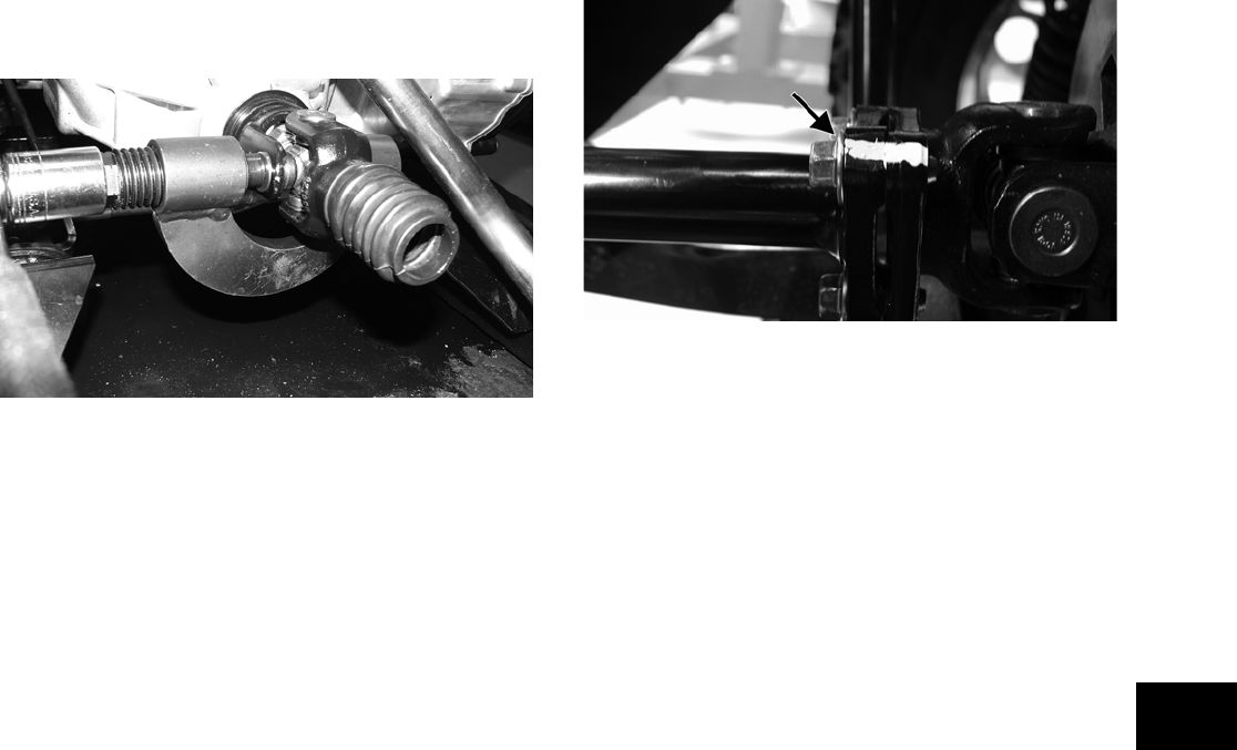
6-29
6
NOTE: Repeat steps 2-3 for the opposite-side
bearing cup.
4. Remove the separator tool from the vise and
install the universal joint cross, bearing cups,
and movable yoke into the fixed yoke using the
same procedure as steps 2-3 except the vise can-
not be used.
PR355
5. Check that the universal joint can be flexed
freely without binding; then apply multi-pur-
pose grease to the splines and install the propel-
ler shaft noting the match marks made prior to
removing.
PR152A

7-1
7
SECTION 7 — SUSPENSION
TABLE OF
CONTENTS
Shock Absorbers …………….…………….…………….….. 7-2
Front A-Arms …………………….…………….……………... 7-3
Rear A-Arms …………………………..…………….……….. 7-5
Wheels and Tires ……………………….…………….…….. 7-7
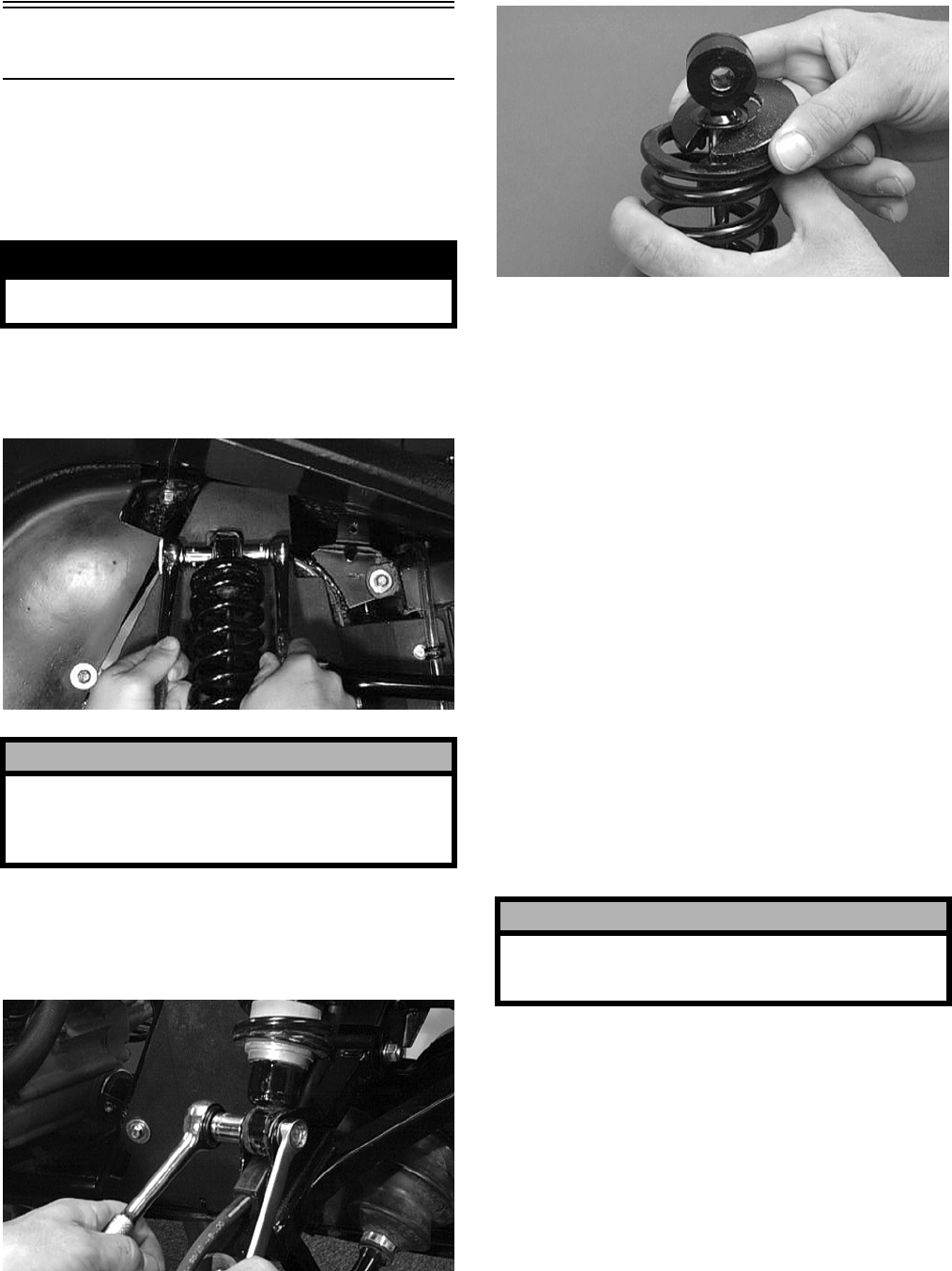
7-2
Shock Absorbers
REMOVING
1. Secure the vehicle on a support stand to elevate
the wheels and to release load on the suspen-
sion.
2. Remove the two cap screws and nuts securing
each front shock absorber to the frame. Account
for bushings and sleeves from each.
AF605D
3. Remove the two cap screws and nut securing
each rear shock absorber to the frame and rear
suspension. Account for bushings and sleeves
from each.
AF626D
4. Compress the shock absorber spring, remove the
retainer, and remove the spring.
AF730D
CLEANING AND INSPECTING
NOTE: Whenever a part is worn excessively,
cracked, or damaged in any way, replacement is
necessary.
1. Clean all shock absorber components in
parts-cleaning solvent.
2. Inspect each shock rod for nicks, pits, rust,
bends, and oily residue.
3. Inspect all springs, spring retainers, shock rods,
dampers, bushings, shock bodies, and eyelets for
cracks, leaks, and bends.
INSTALLING
1. Place the shock absorber spring over the shock
absorber, compress the spring, and install the
retainer.
2. Place bushings and sleeves (where appropriate)
into shock eyelet; then install shock with two
cap screws and nuts. Tighten all nuts to specifi-
cations.
NOTE: The rear shock absorber-to-lower A-arm
torque factor is 2.8 kg-m (20 ft-lb).
3. Remove the vehicle from the support stand.
! WARNING
Make sure the vehicle is solidly supported on the
support stand to avoid injury.
! CAUTION
On the FIS style rear suspension, additional sup-
port stands are necessary to support the rear axle
when the shock absorbers are removed or damage
may occur.
! CAUTION
Do not tighten the nuts beyond the 4.8 kg-m (35
ft-lb) specification or the shock eyelet or mount
WILL be damaged.
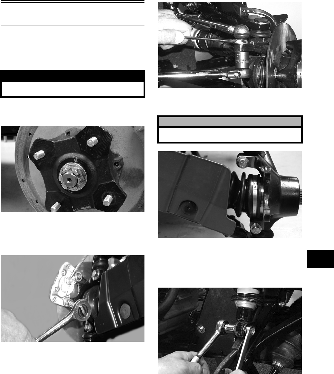
7-3
7
Front A-Arms
REMOVING
1. Secure the vehicle on a support stand to elevate
the front wheels; then remove the wheels.
2. Remove the cotter pin from the nut. Discard the
cotter pin.
PR257
3. Remove the nut securing the hub.
4. Remove the brake caliper. Account for two cap
screws.
CD007
5. Remove the hub assembly.
6. Remove the cotter pin and slotted nut securing
the tie rod end to the knuckle; then remove the
tie rod end from the knuckle.
AF618D
7. Remove the cap screws securing the ball joints
to the knuckle.
PR193
8. Tap the ball joints out of the knuckle; then
remove the knuckle.
9. Remove the lower shock absorber eyelet from
the upper A-arm.
AF626D
10. Remove the cap screws securing the A-arms to
the frame.
! WARNING
Make sure the vehicle is solidly supported on the
support stand to avoid injury.
! CAUTION
Support the knuckle when removing the cap screws
or damage to the threads will occur.
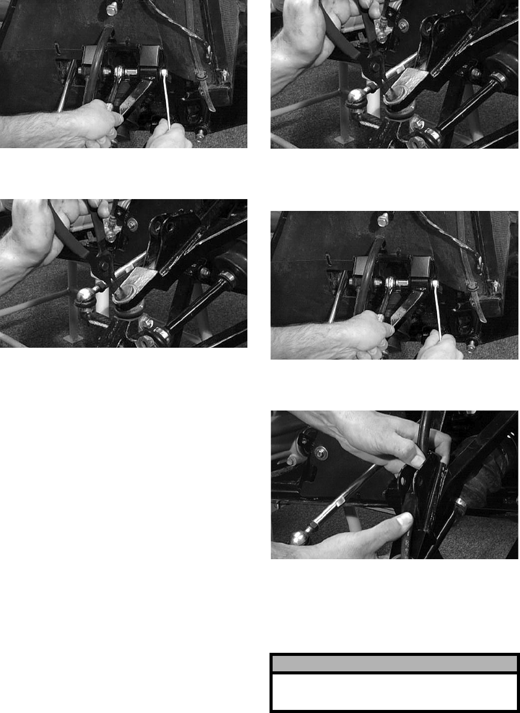
7-4
AF610D
11. Remove the circlip from the ball joint; then
remove the ball joint from the A-arm.
AF616D
CLEANING AND INSPECTING
NOTE: Whenever a part is worn excessively,
cracked, or damaged in any way, replacement is
necessary.
1. Clean all A-arm components in parts-cleaning
solvent.
2. Clean the ball joint mounting hole of all residual
Loctite, grease, oil, or dirt for installing pur-
poses.
3. Inspect the A-arm for bends, cracks, and worn
bushings.
4. Inspect the ball joint mounting holes for cracks
or damage.
5. Inspect the frame mounts for signs of damage,
wear, or weldment damage.
INSTALLING
1. Apply green Loctite #609 to the entire outside
diameter of the ball joint; then install the ball
joint into the A-arm and secure with the circlip.
AF616D
2. Install the A-arm assemblies into the frame
mounts and secure with the cap screws. Only
finger-tighten at this time.
AF610D
3. Route the brake hose through the upper A-arm
shock absorber mount.
AF627D
4. Secure the lower eyelet of the shock absorber to
the upper A-arm. Tighten nut to specifications.
5. Secure the A-arm assemblies to the frame
mounts (from step 2). Tighten the cap screws to
specifications.
! CAUTION
Do not tighten the nut beyond the 4.8 kg-m (35 ft-lb)
specification or the shock eyelet or mount WILL be
damaged.
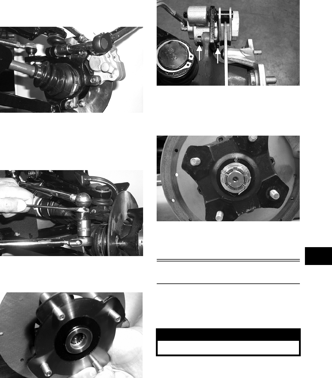
7-5
7
6. Install the knuckle assembly onto the ball joints
and secure with cap screws. Tighten to specifi-
cations.
AF628D
7. Install the tie rod end and secure with the nut.
Tighten to specifications; then install a new cot-
ter pin and spread the pin to secure the nut.
NOTE: During assembly, new cotter pins should
be installed.
AF618D
8. Apply grease to the hub and drive axle splines;
then install the hub assembly onto the drive
axle.
CD009
9. Secure the hub assembly with the nut. Tighten
only until snug.
10. Secure the brake caliper to the knuckle with the
two cap screws. Tighten to specifications.
PR377B
11. Secure the hub nut (from step 9) to the
shaft/axle. Tighten to specifications.
12. Install a new cotter pin and spread the pin to
secure the nut.
PR260
13. Install the wheel and tighten to specifications.
14. Remove the vehicle from the support stand.
Rear A-Arms
REMOVING
1. Secure the vehicle on a support stand to elevate
the wheels.
2. Set the parking brake.
3. Remove the wheel.
4. Remove the cotter pin securing the hex nut; then
remove the hex nut.
! WARNING
Make sure the vehicle is solidly supported on the
support stand to avoid injury.
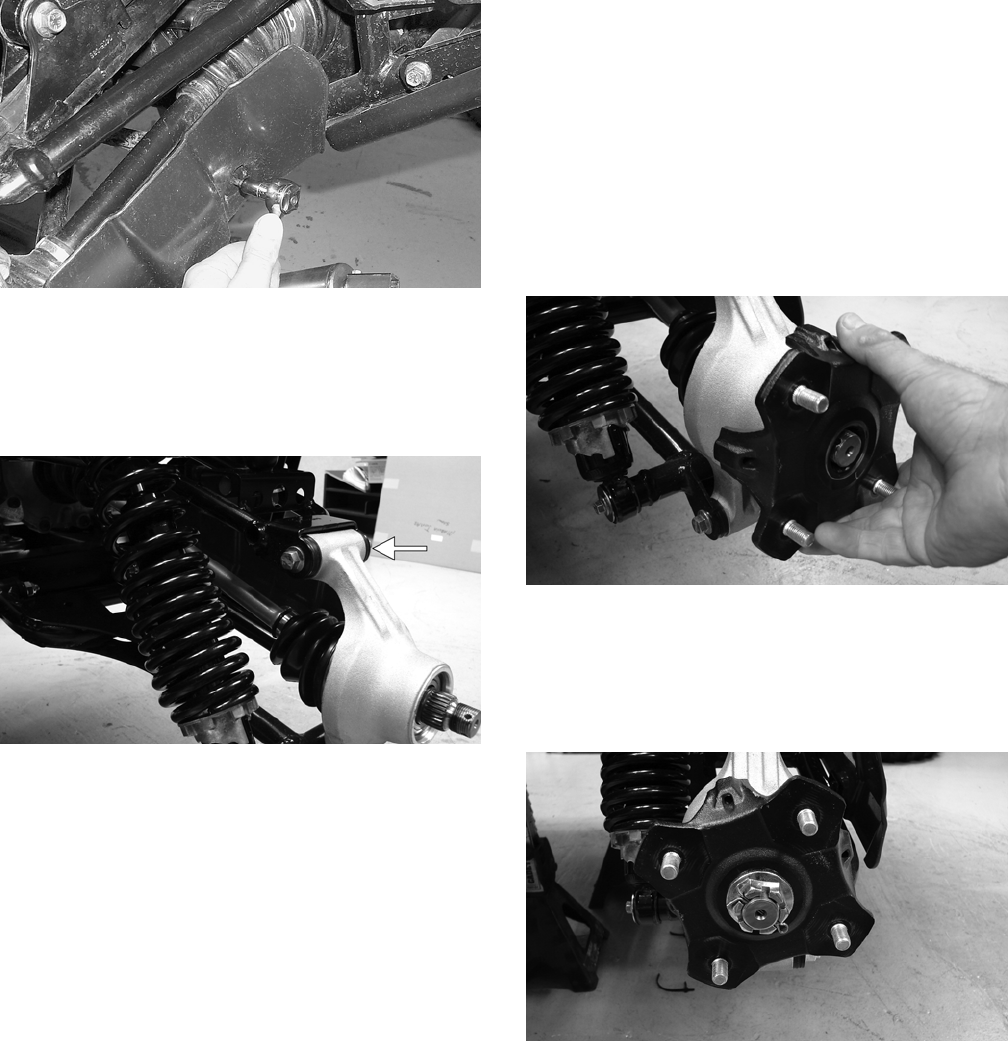
7-6
5. Remove the cap screws and lock nut securing
the shock absorber to the frame and lower
A-arm; then remove the shock absorber.
6. Remove the cap screws securing the boot guard
to the lower A-arm.
AF934
7. Slide the axle out of the knuckle and set aside.
8. Remove the cap screws and lock nuts securing
the knuckle to the A-arms. Discard the lock
nuts.
PR220A
NOTE: Never reuse a lock nut. Once a lock nut
has been removed, it must be replaced with a new
lock nut.
9. Remove the cap screws and lock nuts securing
the A-arms to the frame; then remove the
A-arms.
CLEANING AND INSPECTING
NOTE: Whenever a part is worn excessively,
cracked, or damaged in any way, replacement is
necessary.
1. Clean all A-arm components in parts-cleaning
solvent.
2. Inspect the A-arm for bends, cracks, and worn
bushings.
3. Inspect the frame mounts for signs of damage,
wear, or weldment damage.
INSTALLING
1. Install the A-arm assemblies into the frame
mounts and secure with the cap screws and new
lock nuts. Finger-tighten only at this time.
2. Slide the knuckle onto the drive axle and into
position on the A-arms; then secure the knuckle
to the A-arms with cap screws and new lock
nuts. Tighten to specifications.
3. Tighten the hardware securing the A-arms to the
frame mounts (from step 1) to specifications.
4. Apply grease on the drive axle splines; then
install the hub assembly onto the drive axle.
PR221
5. Secure the hub assembly with the nut. Tighten to
specifications.
6. Install a new cotter pin and spread the pin to
secure the nut.
PR196
7. Secure the shock absorber to the frame with a
cap screw and new lock nut. Tighten to specifi-
cations.
8. Secure the shock absorber to the lower A-arm
with a cap screw and new lock nut. Tighten to
specifications.
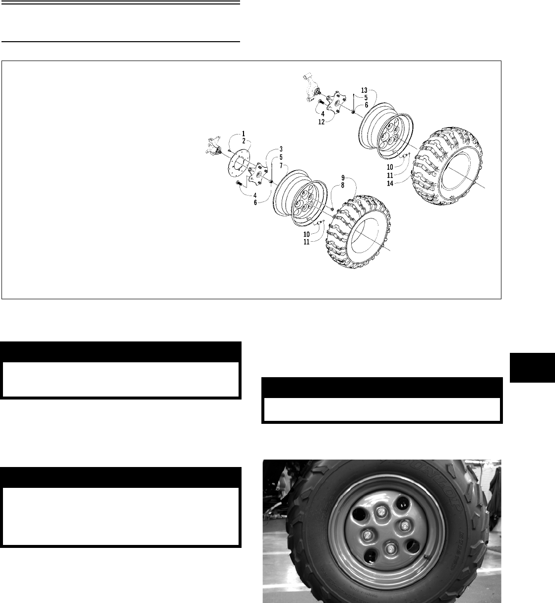
7-7
7
9. Secure the boot guard to the lower A-arm with
the two cap screws. Tighten securely.
10. Install the wheel and tighten to specifications.
11. Remove the vehicle from the support stand.
Wheels and Tires
0739-534
TIRE SIZE
The Prowler XT is equipped with low-pressure
tubeless tires of the size and type listed (see Section
1). Do not under any circumstances substitute tires
of a different type or size.
TIRE INFLATION PRESSURE
Front and rear tire inflation pressure should be 0.70
kg/cm² (10 psi).
REMOVING
1. Secure the vehicle on a support stand to elevate
the wheels.
2. Remove the wheels.
CD006
KEY
1. Machine Screw
2. Brake Disc
3. Wheel Hub — Front
4. Hub Stud
5. Cotter Pin
6. Hex Nut
7. Wheel
8. Mounting Nut
9. Tire — Front
10. Valve Stem
11. Valve Stem Cap
12. Wheel Hub — Rear
13. Wheel
14. Tire — Rear
! WARNING
Use only Arctic Cat approved tires when replacing
tires. Failure to do so could result in unstable vehi-
cle operation.
! WARNING
Do not mix tire tread patterns. Use the same pattern
type on front and rear. Failure to heed warning
could cause poor handling qualities of the vehicle
and could cause excessive drive train damage not
covered by warranty.
! WARNING
Make sure the vehicle is solidly supported on the
support stand to avoid injury.
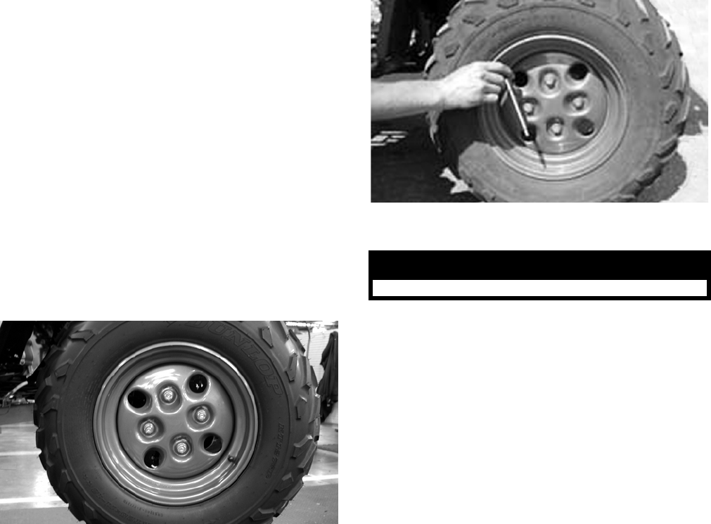
7-8
CLEANING AND INSPECTING
NOTE: Whenever a part is worn excessively,
cracked, or damaged in any way, replacement is
necessary.
1. Clean the wheels and hubs with parts-cleaning
solvent.
2. Clean the tires with soap and water.
3. Inspect each wheel for cracks, dents, or bends.
4. Inspect each tire for cuts, wear, missing lugs,
and leaks.
INSTALLING
1. Install each wheel on its hub.
CD006
2. Tighten to specifications.
CHECKING/INFLATING
1. Using an air pressure gauge, measure the air
pressure in each tire. Adjust the air pressure as
necessary to meet the recommended inflation
pressure.
CD005
2. Inspect the tires for damage, wear, or punctures.
NOTE: If repair is needed, follow the instructions
found on the tire repair kit or remove the wheel and
have it repaired professionally.
NOTE: Be sure all tires are the specified size and
have identical tread pattern.
3. Check the front wheel toe-in and toe-out and
adjust as necessary (see Section 8).
4. Test drive the vehicle on a dry, level surface and
note any pulling to the left or right during accel-
eration, deceleration, and braking.
NOTE: Pulling could be caused by uneven tire
pressure side-to-side, steering alignment out of
adjustment, unequal loading, or improper tire size.
! WARNING
Do not operate the vehicle if tire damage exists.

8-1
8
SECTION 8 — STEERING/FRAME
TABLE OF
CONTENTS
Steering Assembly …………………..…………….……….. 8-2
Steering Wheel……………….…………….…………….….. 8-4
Steering Wheel Shaft ……………….…………….……….. 8-4
Steering Shaft Assembly……….…………….…………... 8-5
Steering Knuckles …….……………..…………….……….. 8-7
Checking/Adjusting Front Wheel Alignment ………… 8-9
Front Bumper Assembly ………………………….……… 8-10
Hood…………….…………….…………….…………….…… 8-10
Fenders ……………..…………….…………….……………. 8-11
Floor …………………….…………….………….……………. 8-12
Belly Panel ……………………………..…………….……… 8-12
Exhaust System ……….……………..……………………. 8-12
Cargo Box ………….…………….…………….……………. 8-13
Adjusting Headlights …….…………….………….……… 8-14
Taillight Assembly…..………………..……………….…… 8-14
Seat….………….…………….…………….…………….…… 8-15
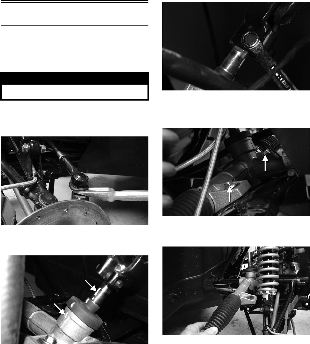
8-2
Steering Assembly
REMOVING
1. Secure the vehicle on a support stand to elevate
the front wheels; then remove the front wheels.
2. Remove the cotter pins and nuts securing the tie
rod ends to the knuckles; then remove the tie rod
ends from the knuckles.
PR301
3. Make matching alignment marks on the pinion
shaft and lower steering shaft joint.
PR333A
NOTE: Any time steering components are disas—
sembled, all connecting components should be
marked for proper alignment during assembling.
4. Remove the cap screw securing the lower steer-
ing shaft joint to the pinion shaft; then slide the
joint free of the pinion.
PR302
5. Remove two cap screws securing the rack and
pinion assembly to the frame. Account for two
nuts and two washers.
PR303A
6. Remove the rack and pinion assembly from the
right-side.
PR305
INSPECTING
NOTE: Whenever a part is worn excessively,
cracked, or damaged in any way, replacement is
necessary.
1. Inspect the tie rod ends for damaged threads,
torn boots, or excessive wear.
2. Inspect the tie rods for bends or deformation.
3. Inspect the rack and pinion-to-tie rod boots for
tears or deterioration.
! WARNING
Make sure the vehicle is solidly supported on the
support stand to avoid injury.
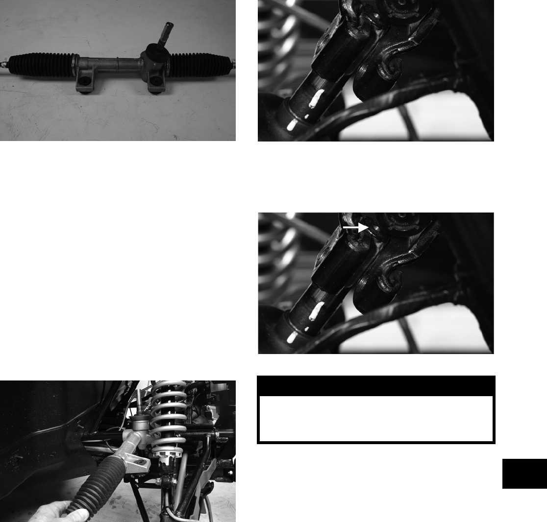
8-3
8
PR307
4. Check boot clamps for security.
5. Check that the rack and pinion assembly oper-
ates smoothly with no binding from full-left to
full-right position.
6. Inspect for grease seepage from the rack and
pinion assembly.
NOTE: The steering assembly is not repairable.
If any of the above items fail inspection, the steer-
ing assembly must be replaced.
INSTALLING
1. Place the rack and pinion assembly into position
from the right-side of the vehicle; then secure
with the two cap screws, washers, and nuts.
Tighten to specifications.
PR305
2. With the rack and the steering wheel centered,
slide the lower steering shaft joint onto the pin-
ion shaft aligning the match marks.
PR309
3. Apply green Loctite #270 to the cap screw; then
secure the lower steering shaft joint to the pinion
shaft making sure the shaft does not protrude
into the joint beyond the clamping surface.
PR309A
4. Tighten the cap screw to specifications; then
check that the steering wheel turns freely.
5. Install the tie rod ends into the steering knuck-
les; then secure with the castle nuts tightened to
specifications.
6. Install the cotter pins and spread to secure.
NOTE: If the holes in the tie rod ends don’t align
with the slots in the castle nuts, tighten the nuts
sufficiently to install the cotter pins.
7. Install the wheels and check the steering system
for full and free travel; then remove the vehicle
from the supports.
! WARNING
Allowing the lower steering shaft joint to extend too
far onto the pinion shaft could cause binding or
lock-up of the steering joint resulting in loss of
steering control.
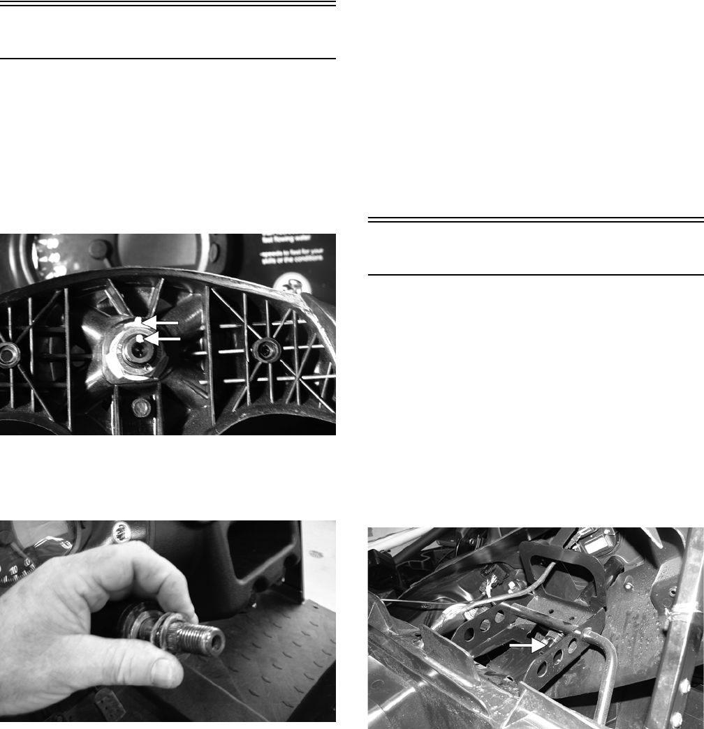
8-4
Steering Wheel
REMOVING
1. Remove the steering wheel cover; then match
mark the steering shaft and steering wheel.
NOTE: Any time steering components are disas—
sembled, all connecting components should be
marked for proper alignment during assembling.
PR324A
2. Remove the nut securing the steering wheel and
remove the steering wheel. Account for the flat
thrust-washer and two wave washers.
PR226
INSPECTING
1. Inspect the steering wheel for cracks, missing
padding, or broken spokes.
2. Inspect the splines for wear.
3. Check that the steering wheel is not bent.
INSTALLING
1. Place the flat thrust-washer and then the two
wave washers onto the steering shaft.
2. Install the steering wheel aligning the two match
marks; then apply a drop of red Loctite #271 to
the threads of the nut and secure the steering
wheel. Tighten to specifications.
NOTE: If a new steering wheel is being installed,
mark the wheel as close as possible to the old
wheel mark; then check for proper positioning with
the front wheels straight forward.
3. Install the steering wheel cover and secure with
the existing hardware. Do not over-tighten.
Steering Wheel Shaft
REMOVING
1. Remove the steering wheel (see Steering Wheel
in this section).
2. Remove the six torx-head screws securing the
dash panel to the frame; then remove the park-
ing brake release handle and jam nut.
3. Slide the dash panel rearward to access the
upper steering shaft joint; then remove the cap
screw securing the upper shaft joint to the steer-
ing wheel shaft.
PR313A
4. Match mark the upper steering shaft joint and
the steering wheel shaft; then remove the steer-
ing wheel shaft. Account for the lower
thrust-washer.
NOTE: Any time steering components are disas-
sembled, all connecting components should be
marked for proper alignment during assembling.
INSPECTING
1. Inspect the steering wheel shaft for excessive
wear.
2. Check for worn splines, cracks, or damaged
threads.
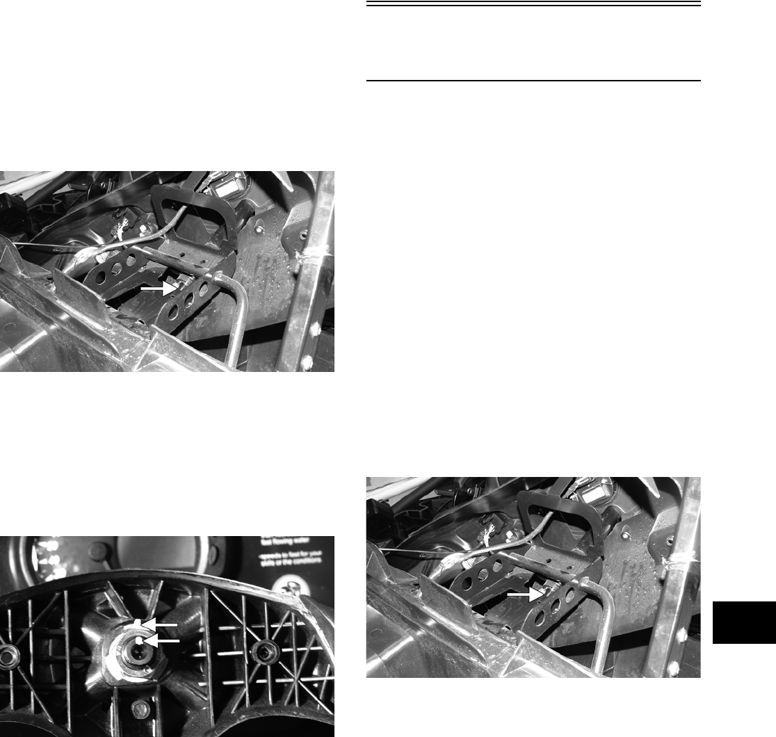
8-5
8
3. Roll the steering wheel shaft on a flat surface to
check for bends.
4. Inspect the nylon bushings in the steering shaft
housing for cracking or excessive wear.
INSTALLING
1. Slide the steering wheel shaft into the steering
housing; then with the lower thrust-washer in
position, align the match marks and slide the
upper steering shaft joint onto the steering wheel
shaft.
PR313A
2. Apply green Loctite #270 to the cap screw; then
install the cap screw in the upper steering shaft
joint. Install the nut and finger-tighten.
3. Align the match marks on the steering wheel
shaft and the steering wheel and slide the steer-
ing wheel onto the splines; then install the nut
and finger-tighten.
PR324A
4. Hold rearward pressure on the steering wheel
and tighten the cap screw (from step 2) to speci-
fications.
5. Remove the steering wheel nut. Apply one drop
of red Loctite #271 to the threads and install the
nut. Tighten to specifications.
6. Check for freedom of movement of the steering
system; then install the steering wheel cover.
7. Move the dash panel into position and secure
with the existing hardware.
Steering Shaft
Assembly
REMOVING
1. Remove the steering wheel (see Steering Wheel
in this section).
2. Remove the six torx-head screws securing the
dash panel to the frame; then remove the park-
ing brake release handle and the jam nut.
3. Slide the dash panel rearward to access the
steering shaft joints; then match mark all con-
necting components for reassembling.
NOTE: Any time steering components are disas-
sembled, all connecting components should be
marked for proper alignment during reassembling.
4. Remove the cap screw securing the upper steer-
ing shaft joint to the steering wheel shaft; then
slide the steering wheel shaft free of the upper
steering shaft joint. Account for one flat
thrust-washer.
PR313A
5. Remove the cap screw securing the lower steer-
ing shaft joint to the pinion shaft; then slide the
steering shaft assembly free and remove through
the opening in the splash panel.
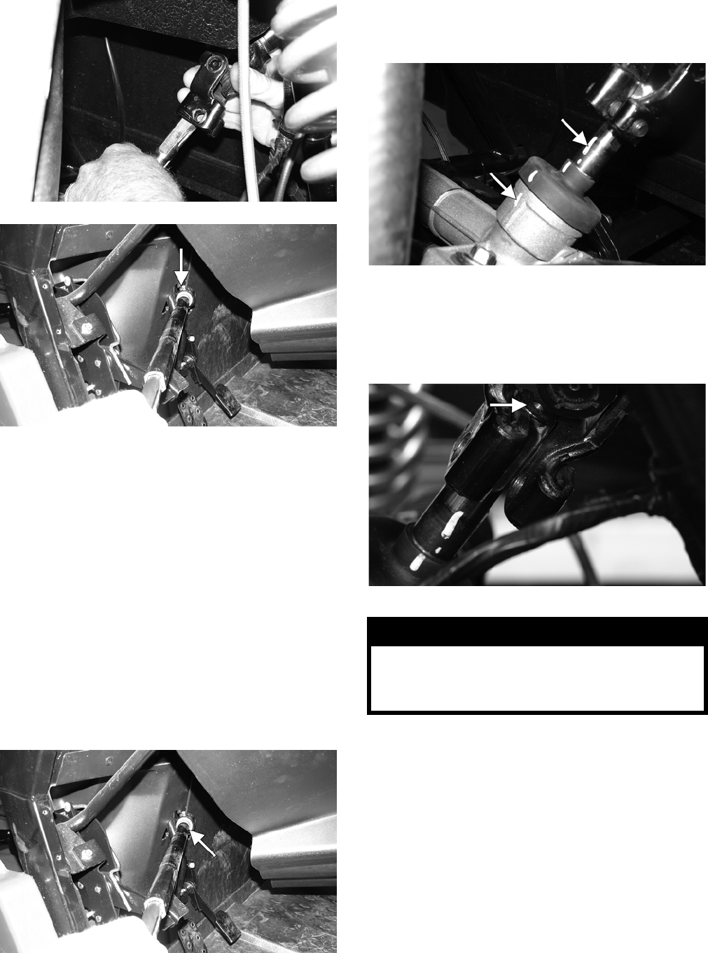
8-6
PR304
PR314B
INSPECTING
NOTE: The steering shaft assembly is not repair-
able or rebuildable. If any damage or excessive
wear is detected, the assembly must be replaced.
1. Inspect the joints for excessive wear or loose-
ness.
2. Inspect welds and slip-joints for cracks.
3. Check for excessive wobble in the slip-joint.
INSTALLING
1. Place the steering shaft assembly into position
through the opening in the splash panel.
PR314A
2. Align the match marks on the pinion shaft and
the lower steering shaft joint; then slide the
steering shaft joint onto the pinion shaft.
PR333A
3. Apply green Loctite #270 to the cap screw; then
secure the lower steering shaft joint to the pinion
shaft making sure the pinion shaft does not pro-
trude into the joint beyond the clamping surface.
Tighten to specifications.
PR309A
4. Align the match mark on the upper steering
shaft joint with the mark on the steering wheel
shaft; then install the flat thrust-washer and the
steering shaft joint onto the steering wheel shaft.
! WARNING
Allowing the lower steering shaft joint to extend too
far onto the pinion shaft could cause binding or
lock-up of the steering joint resulting in loss of
steering control.
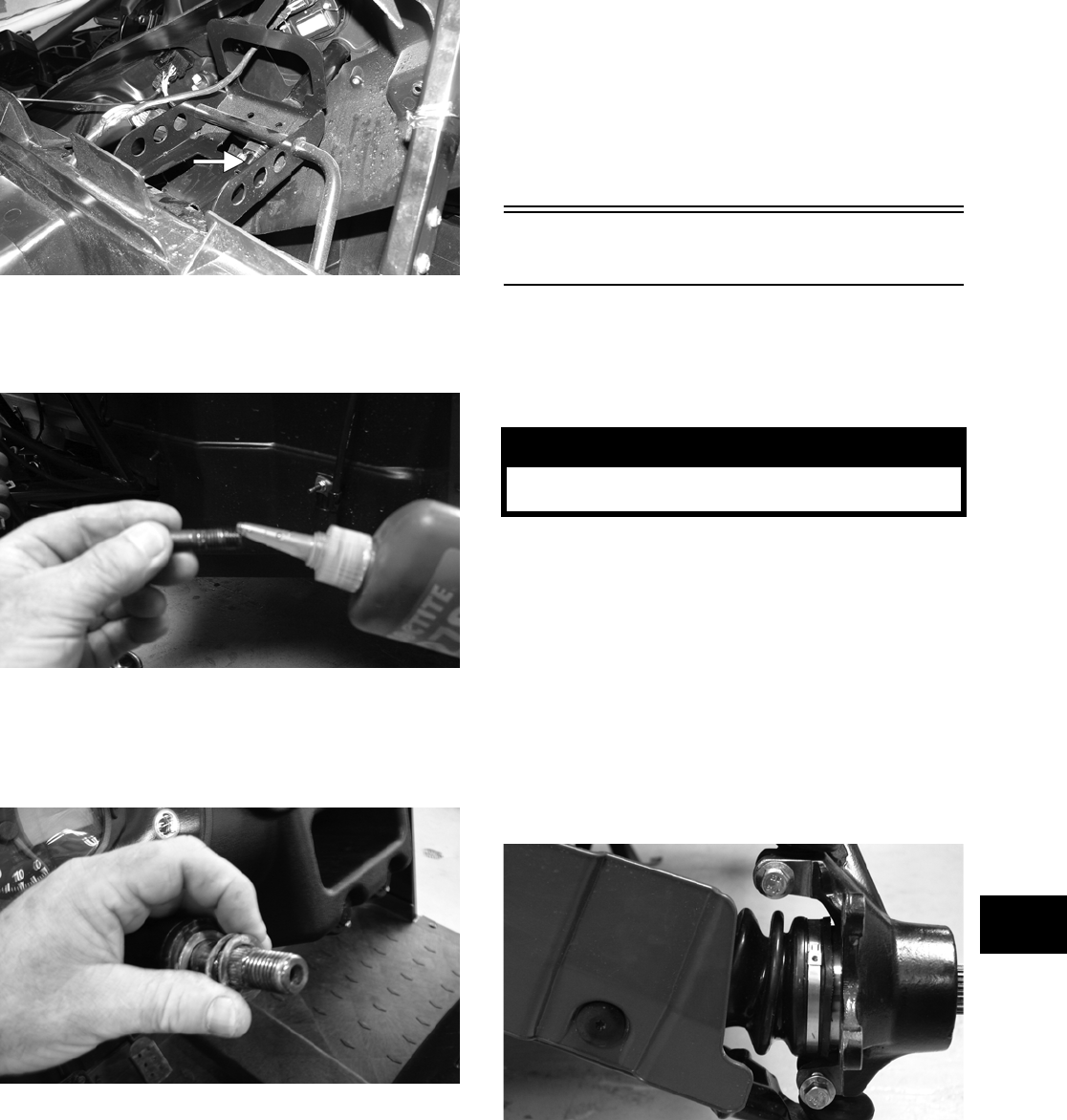
8-7
8
PR313A
5. Apply green Loctite #270 to the cap screw; then
install the cap screw in the upper steering shaft
joint and finger-tighten.
PR310
6. Install the flat thrust-washer and two wave
washers on the steering wheel shaft; then align
the match marks on the steering wheel shaft and
the steering wheel. Loosely install the nut.
PR226
7. Hold rearward pressure on the steering wheel
and tighten the cap screw (from step 5) to speci-
fications.
8. Remove the steering wheel nut and apply one
drop of red Loctite #271 to the threads. Install
the nut and tighten to specifications.
9. Check that the steering wheel turns freely from
full-right to full-left; then install the steering
wheel cover.
NOTE: If the steering is stiff or the steering
wheel is difficult to turn, loosen and then tighten
the cap screw on the upper steering shaft joint.
Check the steering wheel nut for specified torque
value.
10. Place the dash panel into position and secure
with the six torx-head screws.
Steering Knuckles
REMOVING AND DISASSEMBLING
1. Secure the vehicle on a support stand to elevate
the wheel; then remove the wheel.
2. Remove the cotter pin from the axle.
3. Remove the nut securing the hub.
4. Remove the brake caliper.
5. Remove the hub assembly.
6. Remove the cotter pin from the tie rod end and
remove the tie rod end from the knuckle.
7. Remove the two cap screws securing the ball
joints in the knuckle.
PR193
8. Tap the ball joint end out of the knuckle; then
remove the knuckle.
9. Remove the snap ring securing the bearing in
the knuckle; then press the bearing out of the
knuckle.
! WARNING
Make sure the vehicle is solidly supported on the
support stand to avoid injury.
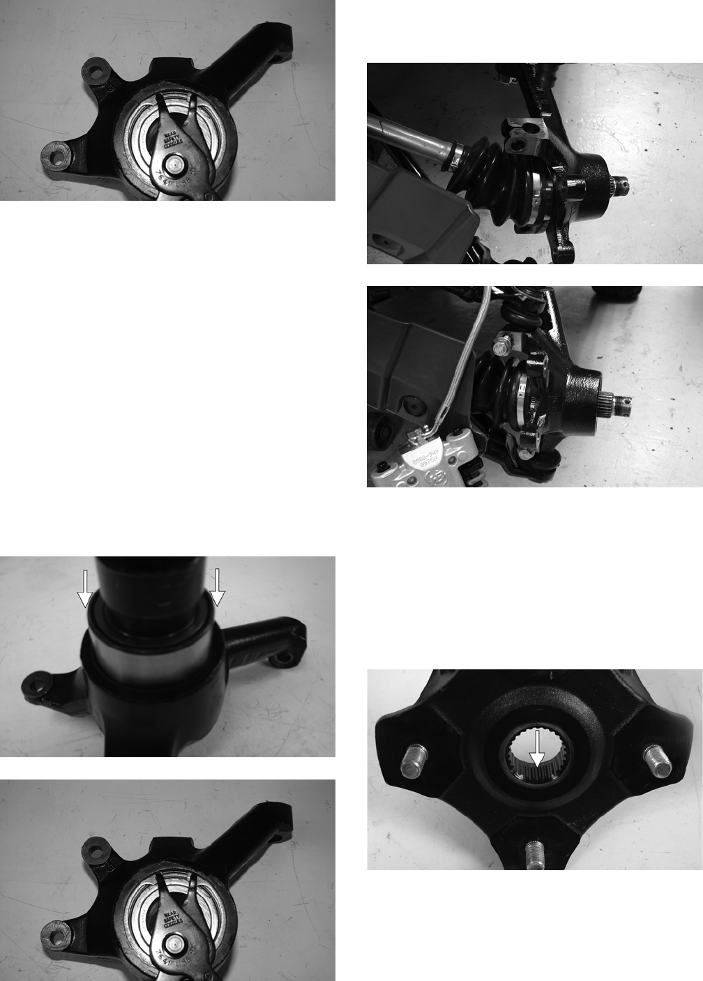
8-8
PR289
CLEANING AND INSPECTING
NOTE: Whenever a part is worn excessively,
cracked, or damaged in any way, replacement is
necessary.
1. Clean all knuckle components.
2. Inspect the bearing for pits, scoring, rusting, or
premature wear.
3. Inspect the knuckle for cracks, breaks, or galling
of the bearing surface.
ASSEMBLING AND INSTALLING
1. Using a suitable press and driver, press the bear-
ing into the knuckle until firmly seated; then
install the snap ring.
PR292A
PR289
2. Install the knuckle to the upper and lower ball
joints and secure with the two cap screws.
Tighten to specifications.
PR202
PR203
3. Install the tie rod end and secure with the nut.
Tighten to specifications; then install a new cot-
ter pin and spread the pin.
NOTE: During assembling, new cotter pins
should be installed.
4. Apply a small amount of grease to the hub
splines.
PR290A
5. Install the hub assembly onto the splines of the
shaft.
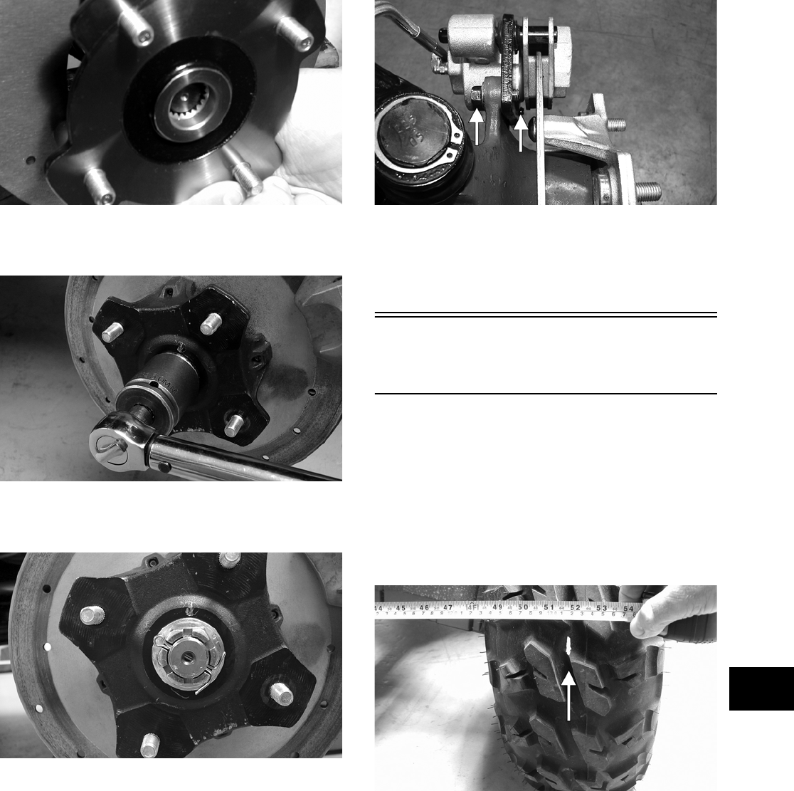
8-9
8
CD009
6. Secure the hub assembly with the nut. Tighten to
specifications.
PR256
7. Install a new cotter pin and secure by spreading
as shown.
PR260
NOTE: If the hole in the axle shaft does not align
with the slots in the castle nut, tighten the nut until
the hole and slots align.
8. Secure the brake caliper to the knuckle with the
two cap screws. Tighten to specifications.
PR377B
9. Install the wheel; then using a crisscross pattern,
tighten to specifications.
10. Remove the vehicle from the support stand.
Checking/Adjusting
Front Wheel Alignment
NOTE: All measurements and adjustments must
be made with the vehicle unloaded.
Mark the center-line of the front tires at the front
and rear of the tire; then using a tape measure, mea-
sure and record the distance between the marks at
the front and rear. The front measurement should be
6-12 mm (1/4-1/2 in.) greater than the rear measure-
ment (toe-out).
PR087A
To adjust the wheel alignment, use the following
procedure.
1. Center the steering wheel; then using an
open-end wrench to hold the tie rod ends, loosen
the right-side and left-side jam nuts.
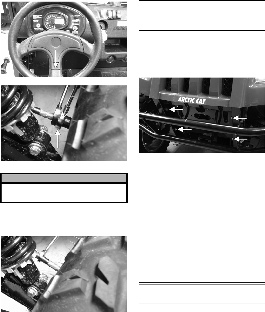
8-10
PR084A
PR085A
2. Turn the left-side and right-side tie rods in equal
increments to achieve the proper toe-out; then
tighten the jam nuts securely.
PR086
Front Bumper
Assembly
REMOVING
To remove the front bumper assembly, remove four
cap screws and nuts. Account for four lock washers
and eight flat washers.
PR327A
CLEANING AND INSPECTING
NOTE: Whenever a part is worn excessively,
cracked, or damaged in any way, replacement is
necessary.
1. Clean all bumper components with parts-clean-
ing solvent.
2. Inspect all welds for cracking or bending.
INSTALLING
To install the front bumper assembly, place the
bumper assembly into position on the frame; then
secure with the four cap screws and nuts making
sure the flat washers and lock washers are properly
positioned. Tighten securely.
Hood
REMOVING
1. Open the hood; then disconnect the four head-
light connectors and remove two nylon ties.
! CAUTION
Always use a wrench to hold the tie rod ends when
loosening or tightening the jam nuts or damage to
the boots could occur.
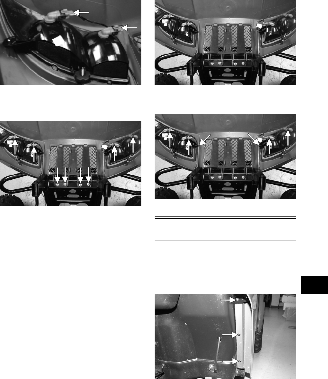
8-11
8
PR328A
2. Loosen but do not remove the four cap screws
and flange nuts securing the hood hinge to the
frame; then lower the hood.
PR332A
3. Finish removing the cap screws and flange nuts
(from step 2); then remove the hood assembly.
CLEANING AND INSPECTING
NOTE: Whenever a part is worn excessively,
cracked, or damaged in any way, replacement is
necessary.
1. Clean all hood components with parts-cleaning
solvent and soap and water.
2. Inspect the hood for cracks and/or loose fasten-
ers.
3. Inspect for any missing decals.
INSTALLING
1. Place the hood into position on the vehicle; then
install the two outside cap screws and flange
nuts. Finger-tighten only at this time.
2. Open the hood; then install the remaining two
cap screws and flange nuts. Tighten all four
securely.
PR332
3. Connect the four headlight connectors; then
secure the wires with two new nylon ties.
PR332B
Fenders
REMOVING
To remove the fenders, remove three torx-head
screws securing each fender to the frame. Account
for a stiffener bracket on the front fenders.
PR311A
INSTALLING
To install the fenders, place the appropriate fender
into position and secure with existing hardware.
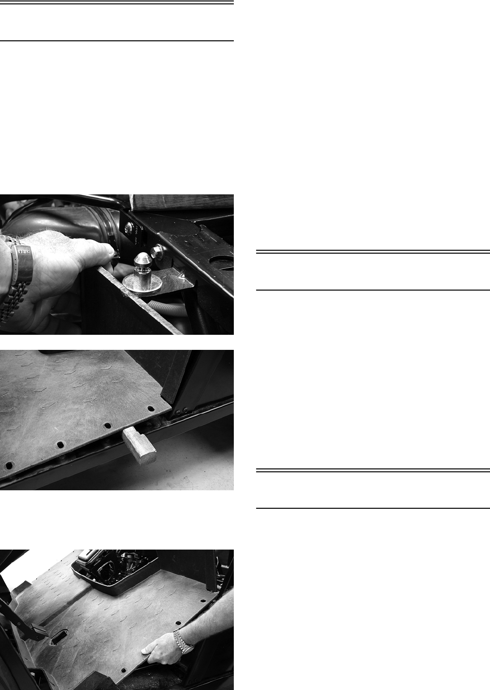
8-12
Floor
REMOVING
1. Remove the seats and center console.
2. Remove twelve cap screws and two self-tapping
screws securing the floor to the frame.
3. While pulling forward on the upper-rear of the
floor, lift the rear part of the floor above the seat
lock stud; then insert a small wood block to hold
in position.
PR163
PR164
4. From the opposite side of the vehicle repeat step
3; then lift the rear of the floor up and lift the
floor out of the vehicle.
PR165
CLEANING AND INSPECTING
NOTE: Whenever a part is worn excessively,
cracked, or damaged in any way, replacement is
necessary.
1. Clean the floor with soap and water.
2. Inspect the floor for cracks or holes.
INSTALLING
1. Place the front of the floor into position in the
vehicle first; then lower the rear and push past
the seat lock studs.
2. Secure the floor with twelve cap screws and two
self-tappings screws.
3. Install the center console and seats making sure
the seats lock securely into position.
Belly Panel
REMOVING
1. Remove the body screws securing the belly
panel to the underside of the frame.
2. Remove the belly panel.
INSTALLING
1. Place the belly panel into position on the under-
side of the frame.
2. Install the body screws. Tighten securely.
Exhaust System
REMOVING MUFFLER
1. Remove the two exhaust springs at the muf-
fler/exhaust pipe juncture.
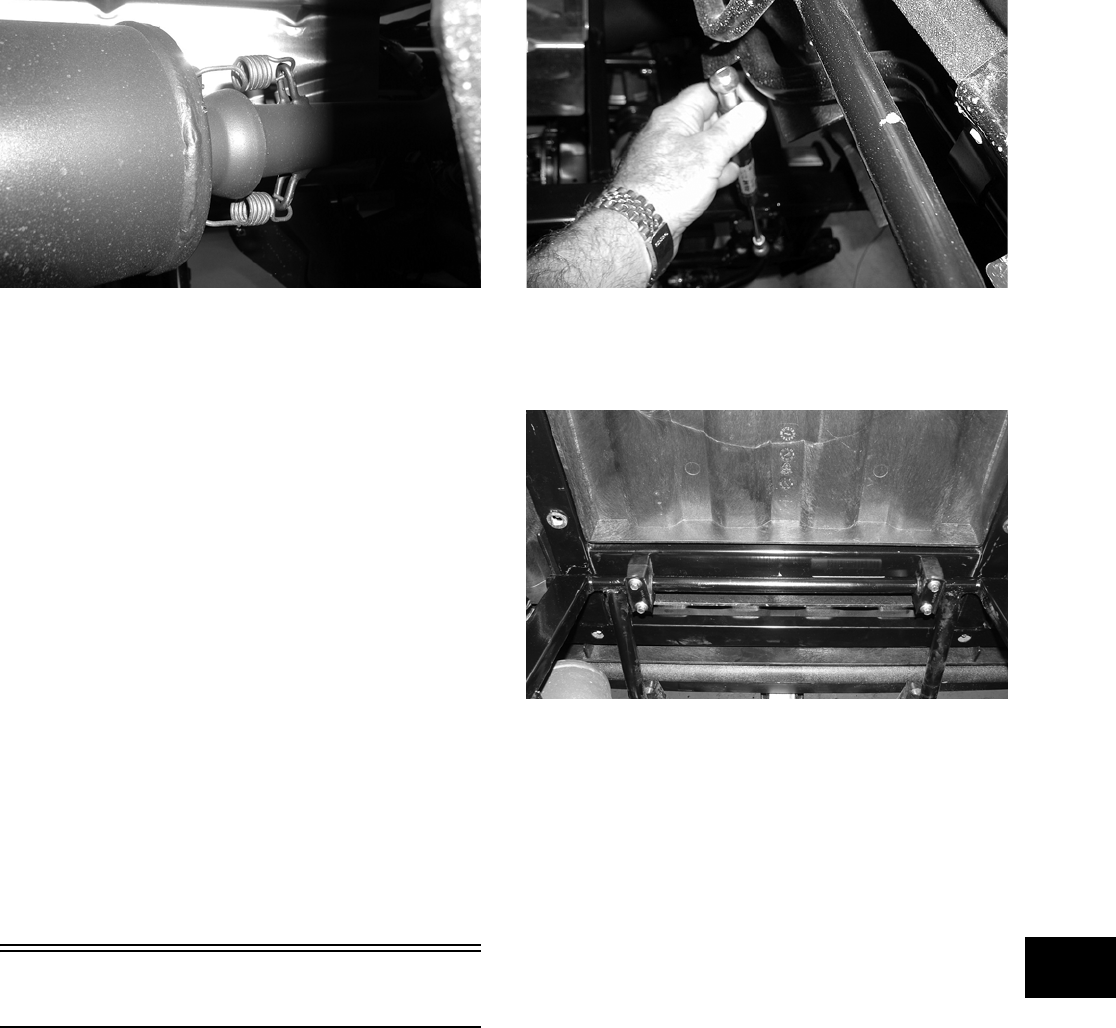
8-13
8
PR131
2. Slide the muffler assembly rearward and clear of
the holder pins.
INSPECTING MUFFLER
NOTE: Whenever a part is worn excessively,
cracked, or damaged in any way, replacement is
necessary.
1. Inspect muffler externally for cracks, holes, and
dents.
2. Inspect the muffler internally by shaking the
muffler back and forth and listening for rattles
or loose debris inside the muffler.
NOTE: For additional details on cleaning the
muffler/spark arrester, see Section 2.
INSTALLING MUFFLER
1. Place the muffler onto the holder pins and slide
forward into position.
2. Secure the muffler to the exhaust pipe with the
two exhaust springs.
Cargo Box
REMOVING
1. Raise the cargo box; then disengage the lift sup-
port socket from the ball. The cargo box will tilt
fully rearward.
PR102
2. Loosen but do not remove the four shoulder cap
screws securing the pivot housings to the cargo
box.
PR335
3. Lower the cargo box; then remove the four cap
screws (from step 2).
4. With the help of an assistant or an adequate lift,
remove the cargo box from the vehicle.
Account for four pivot housings.
CLEANING AND INSPECTING
NOTE: Whenever a part is worn excessively,
cracked, or damaged in any way, replacement is
necessary.
1. Clean all cargo box components with soap and
water.
2. Inspect the cargo box for cracks, tears, and loose
hardware.
3. Inspect the welds of the cargo box frame for
cracking or bending.
4. Inspect the cargo box gate latches for smooth
operation.
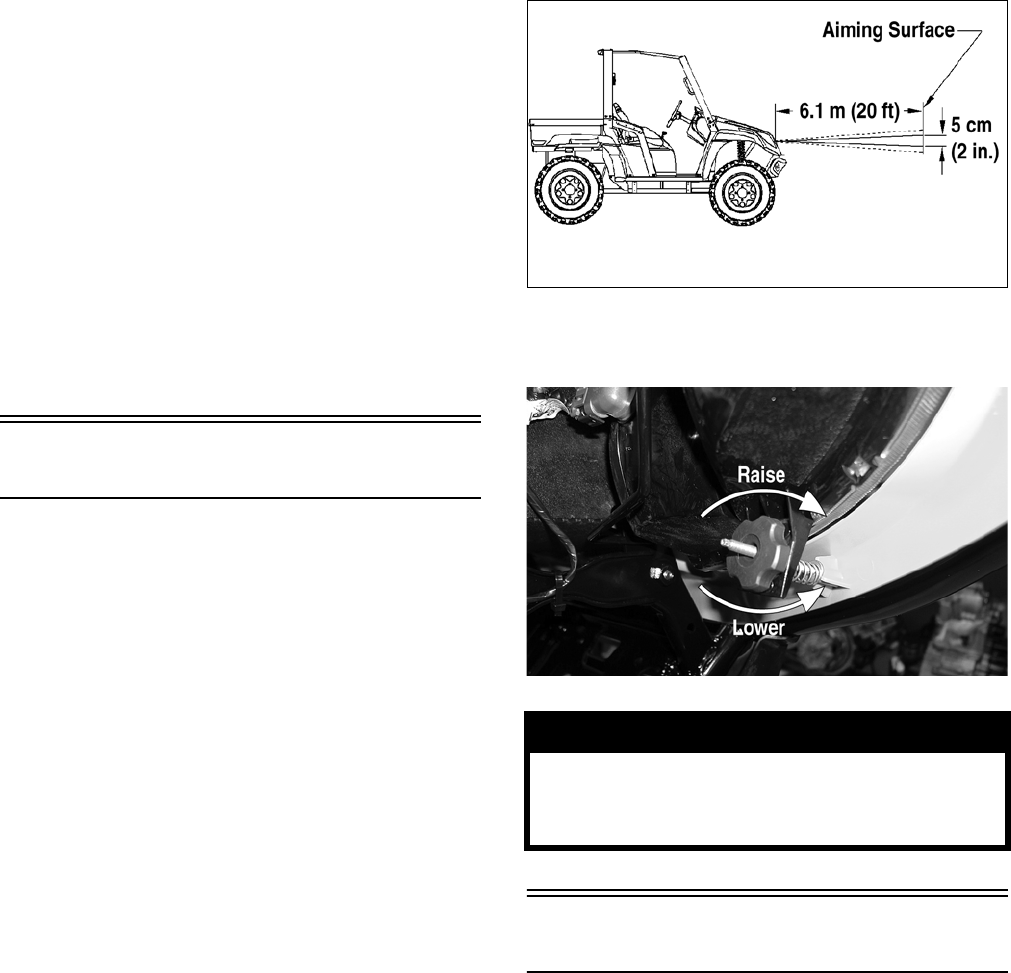
8-14
INSTALLING
1. With the help of an assistant or an adequate lift,
set the cargo box into position on the frame;
then position the two upper pivot housings
between the cargo box and frame. Lightly
grease the pivot housings.
2. Align the holes in the upper pivot housings with
the holes in the cargo box; then install the lower
pivot housings and secure with the four shoulder
cap screws. Tighten to specifications.
3. Raise the cargo box; then connect the lift sup-
port to the ball.
4. Lower the cargo box and lock into position.
Adjusting Headlights
The headlights can be adjusted vertically. The geo-
metric center of the HIGH beam light zone is to be
used for vertical aiming.
1. Position the vehicle on a level floor so the head-
lights are approximately 6.1 m (20 ft) from an
aiming surface (wall or similar aiming surface).
NOTE: There should be an average operating
load on the vehicle when adjusting the headlight
aim.
2. Measure the distance from the floor to the
mid-point of each headlight.
3. Using the measurements obtained in step 2,
make horizontal marks on the aiming surface.
4. Make vertical marks which intersect the hori-
zontal marks on the aiming surface directly in
front of the headlights.
5. Switch on the lights. Make sure the HIGH beam
is on. DO NOT USE LOW BEAM.
6. Observe each headlight beam aim. Proper aim is
when the most intense beam is centered on the
vertical mark 5 cm (2 in.) below the horizontal
mark on the aiming surface.
0740-647
7. Turn the adjustment knob counterclockwise to
lower the beam and clockwise to raise the beam.
CD714A
Taillight Assembly
REMOVING
1. Remove two torx-head screws securing the tail-
light assembly to the rear canopy tube; then
rotate the taillight assembly left or right to allow
the connector to clear the access opening.
! WARNING
Do not operate the vehicle unless the headlight
beam is adjusted properly. An incorrectly adjusted
beam will not provide the operator the optimum
amount of light.
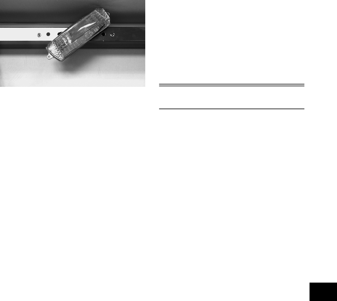
8-15
8
PR056
2. Disconnect the three-prong connector from the
bulb socket and remove the taillight assembly.
INSPECTING
NOTE: Whenever a part is worn excessively,
cracked, or damaged in any way, replacement is
necessary.
1. Inspect wiring harness, three-prong connector,
lens, base, cap screws, and socket for damage.
2. Inspect all wires for corroding, pinching, and
cracking.
3. Inspect the bulb for wattage, voltage, and proper
operation.
INSTALLING
1. Connect the three-prong connector to the bulb
socket; then place the taillight assembly into
position on the rear canopy tube.
2. Install the two torx-head screws and tighten
securely.
Seat
REMOVING/INSTALLING
1. To remove the seat, pull the seat lock lever up.
Raise the front of the seat and slide it forward.
2. To install the seat, slide the rear of the seat into
the seat retainers and push down firmly on the
front of seat. The seat should automatically lock
into position.

9-1
9
SECTION 9 — CONTROLS/INDICATORS
TABLE OF
CONTENTS
Master Cylinder Assembly………………………….…….. 9-2
Accelerator Pedal ..…………….………….…………….….. 9-3
2WD/4WD Selector ……………………….…………….….. 9-3
Front Differential Lock ……..………….…………….…….. 9-3
Low Range/High Range/Neutral/Reverse Lever…… 9-4
Speedometer/Tachometer/LCD…….………….……….. 9-4
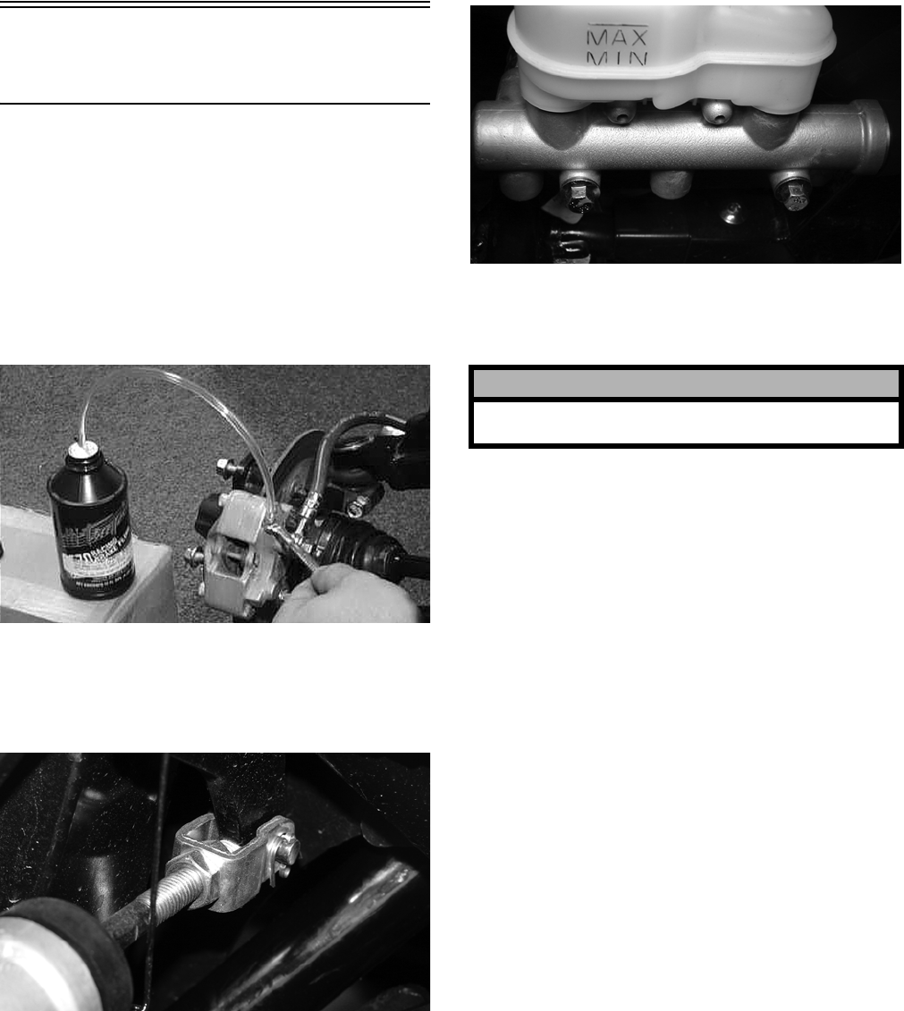
9-2
Master Cylinder
Assembly
NOTE: The master cylinder is a non-serviceable
component; it must be replaced as an assembly.
REMOVING
1. Slide a piece of flexible tubing over one of the
wheel bleeder valves and direct the other end
into a container. Remove the reservoir cover;
then open the bleeder valve. Allow the brake
fluid to drain until the reservoir is empty.
AF637D
2. Remove the cotter pin and pivot pin from the
yoke; then remove two cap screws and flange
nuts securing the master cylinder assembly to
the frame.
PR338
PR336
3. Remove the oil bolt securing the banjo fittings
to the master cylinder; then remove the master
cylinder. Discard the three crush washers.
INSPECTING
NOTE: Whenever a part is worn excessively,
cracked, or damaged in any way, replacement is
necessary.
1. Inspect the master cylinder push rod and clevis
for wear, bending, or elongation of clevis holes.
2. Inspect the push rod boot for tears or deteriora-
tion.
3. Inspect the reservoir for cracks and leakage.
4. Inspect the brake hose for cracks and deteriora-
tion and the condition of the banjo fittings.
INSTALLING
1. Place the master cylinder into position; then
using three new crush washers, secure the two
banjo fittings to the master cylinder. Tighten to
specifications.
2. Secure the master cylinder assembly to the
frame with two cap screws and two flange nuts.
Tighten to specifications.
3. Install the pivot pin and secure with a new cotter
pin.
4. Fill the master cylinder and bleed the brake sys-
tem (see Section 2).
! CAUTION
Brake fluid is highly corrosive. Do not spill brake
fluid on any surface of the vehicle.
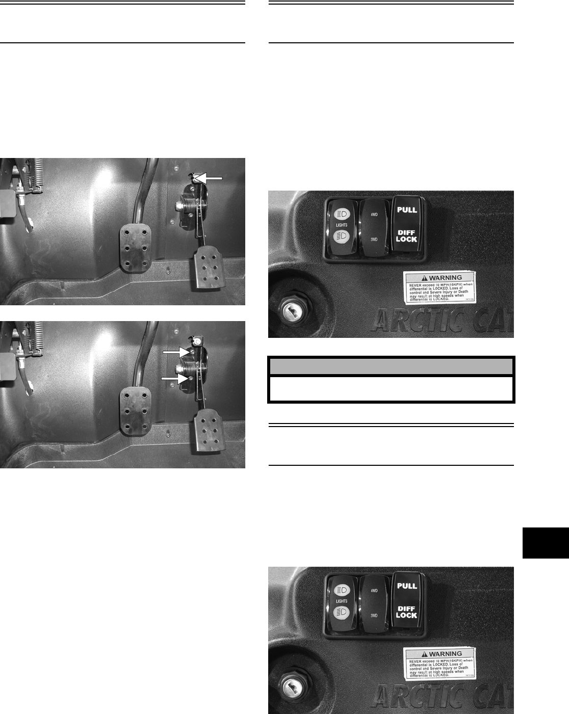
9-3
9
Accelerator Pedal
REMOVING
To remove the accelerator pedal, dislodge the throt-
tle cable holding grommet from the actuator arm;
then remove two torx-head screws and nuts securing
the accelerator pedal assembly to the splash panel
and remove the accelerator pedal.
PR342B
PR342C
INSTALLING
To install the accelerator pedal, align the mounting
holes with the holes in the splash panel and secure
with the two torx-head screws and nuts; then snap
the throttle cable holding grommet into the actuator
arm.
ADJUSTING
To adjust the throttle cable, see Section 2.
2WD/4WD Selector
The automatic drive selector allows the operator to
operate in either 2-wheel drive (rear wheels) or
4-wheel drive (all wheels). For normal riding on
flat, dry, hard surfaces, 2-wheel drive should be suf-
ficient. In situations of aggressive trail conditions,
4-wheel drive would be the desired choice.
To either engage or disengage the front wheels,
move the switch to the 4WD position or to the 2WD
position.
PR083
Front Differential Lock
The front differential lock allows the operator to
mechanically lock the differential to apply equal
power to both front wheels. To engage the front dif-
ferential lock, pull the DIFF LOCK toggle out; to
disengage the front differential lock, push the DIFF
LOCK toggle in.
PR083
! CAUTION
Do not attempt to engage or disengage the front dif-
ferential while the vehicle is moving.
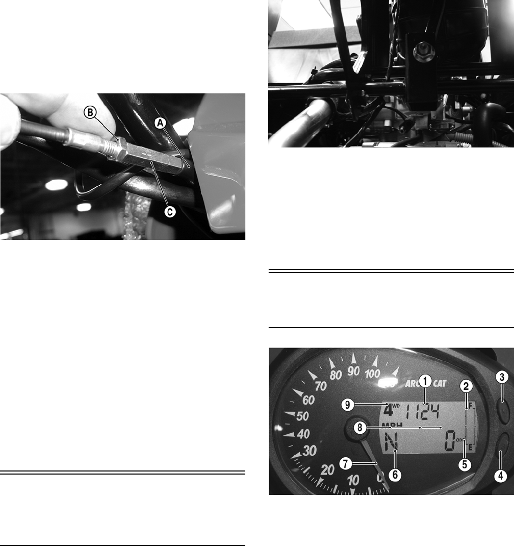
9-4
ADJUSTING CABLE
1. With the toggle in the pushed-in position, slide
the rubber protector sleeve (A) off the cable near
the toggle; then loosen the jam nut (B) and turn
the cable adjuster (C) to achieve 6.35 mm (0.250
in.) free-travel measured at the toggle.
CD560A
2. Select the 2WD position on the 2WD/4WD
selector switch; then turn the ignition switch to
the ON position and select the LOCK position
on the toggle. The front drive actuator should
operate engaging four-wheel drive.
NOTE: It may be necessary to turn the steering
wheel or to rock the vehicle forward and backward
to align the differential lock splines and allow
engagement.
3. Return the toggle to the pushed-in position and
listen for the front drive actuator to operate.
4. Turn the ignition switch to the OFF position.
Tighten the jam nut securely; then install the
protector sleeve on the adjuster assembly.
Low Range/
High Range/Neutral/
Reverse Lever
REMOVING
1. Remove the seats and center console.
2. Remove the flange nut and shoulder screw from
the shift lever pivot; then remove the shift lever.
Account for the shifter spring.
PR340
INSTALLING
1. With the shifter spring in place on the shift lever,
install the shift lever onto the shifter axle.
2. Install the shoulder screw and secure with the
flange nut. Tighten to specifications.
Speedometer/
Tachometer/LCD
CF094B
1. Clock/Engine Hour Meter — The clock function
indicates time in the 12 hour mode; the hour
meter indicates the total time the vehicle has run
and cannot be reset to zero. To set the clock, use
the following procedure.
A. With the ignition switch in the ON position,
press and release the Mode Button (3) until
the Clock/Engine Hour Meter (1) is dis-
played; then (if necessary) press and release
the Set/Reset Button (4) to the clock display.
B. Press and hold the Set/Reset Button (4) until
the minutes stop scrolling and the hour dis-
play starts to scroll. Momentarily release
when the correct hour is displayed; then
repeatedly press and release the Set/Reset
Button (4) until the correct minutes are dis-
played.
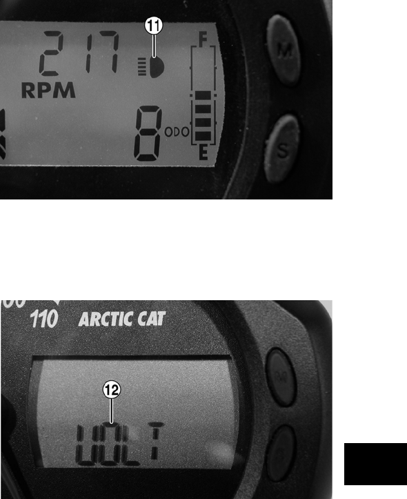
9-5
9
NOTE: Approximately two seconds after releas—
ing either Button, the LCD will return to normal
operation.
NOTE: Clock memory power is supplied through
the 15-amp accessory fuse and verified during
gauge “power-up” and reset. In the event of clock
memory power failure (blown fuse, etc.), the gauge
will “power-up,” reset, and shut down repeatedly
until clock memory power is restored. Always
check the 15-amp accessory fuse if this gauge
condition is noted.
NOTE: The engine hour meter will not activate
until engine speed exceeds 500 RPM.
2. Fuel Level Indicator — Indicates approximate
amount of gasoline in the gas tank.
NOTE: When the bottom segment flashes,
approximately 3.8 L (1.0 U.S. gal.) of gasoline
remains in the tank.
3. Mode Button — Shifts the digital gauge through
three modes: speed/tachometer, distance, and
time.
NOTE: The Mode Button must be pressed and
released to shift modes. Approximately two sec-
onds after the Mode Button is released, the digital
gauge will return to full display.
4. Set/Reset Button — In conjunction with the Mode
Button, sets and resets various displays on the
digital gauge. Also used to switch from speed-
ometer function to tachometer function on the
speedometer/tachometer gauge.
5. Odometer/Trip Meter (#1 and #2) — Odometer
registers the total distance the vehicle has trav-
eled. Trip meters can register two distances (for
instance, #1 could register trip distance and #2
could register distance between stops). The trip
meters can be reset while the odometer only reg-
isters accumulated miles/kilometers.
NOTE: To select the odometer (ODO), trip #1
(T1), or trip #2 (T2), press the Mode Button (3) to
select the distance mode; then press the Set/Reset
Button (4) to select the desired display. Hold the
Set/Reset button down to reset trip meters.
6. Gear Position Indicator — Indicates which gear-
shift position is selected.
7. Speed/Tach Indicator — Indicates approximate
vehicle speed in mph or k/ph when speedometer
function is selected or rpm when tachometer
function is selected.
8. Speed Function Display — Displays which speed
function (MPH, TACH, K/PH) is being indi-
cated by the Speed/Tach indicator.
NOTE: The speed and tach functions may be
switched by pressing the Set/Reset Button.
9. Differential Lock Indicator — Displays LOCK
when the differential lock has been engaged.
10. Drive Select Indicator — Displays 4WD when
selected by the 2WD/4WD selector switch or
when the differential lock is engaged.
11. High Beam Indicator — The High Beam icon will
appear only when the lights are on high beam.
CF101A
12. Battery Condition Indicator — The word VOLT
will flash on the LCD whenever a low voltage
(< 9 DC volts) or high voltage (>16 DC volts) is
detected.
CF098A
13. Temperature Indicator — The high temperature
icon will flash and the speed/tach needle will
sweep full scale if the engine overheats. After 30
seconds, the speed/tach needle will return to
normal, but the temperature icon will continue
to flash. The icon should not be visible during
normal operation.
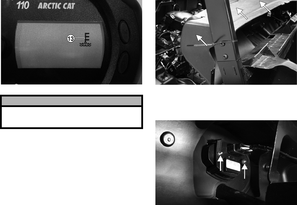
9-6
CF099A
REPLACING
SPEEDOMETER/TACHOMETER/LCD
To replace the speedometer, use the following pro-
cedure.
1. Remove the six torx-head screws securing the
dash panel to the frame; then remove the park-
ing brake handle and jam nut.
2. Slide the dash panel to the rear sufficiently to
access the components.
PR181A
3. Remove two nuts securing the gauge assembly
to the dash; then unplug the multi-pin connector
and remove the gauge from the vehicle.
PR284A
4. Place the new gauge into the dash panel open-
ing; then place the gauge holder over the mount-
ing screws and secure with the two nuts.
5. Plug the multi-pin connector into the gauge;
then turn the ignition switch to the ON position
and check gauge functions.
6. Slide the dash into position and secure with the
six torx-head screws.
7. Install the parking brake handle and jam nut.
! CAUTION
Continued operation of the vehicle with high engine
temperature may result in engine damage or prema-
ture wear.

10-1
10
SECTION 10 — AIDS FOR MAINTENANCE
TABLE OF
CONTENTS
Torque Specifications ………………….…………….…… 10-2
Torque Conversions ……………..…………….…………. 10-3
Tightening Torque (General Bolts) …………………… 10-3

10-2
Torque Specifications
* w/Blue Loctite #243
** w/Red Loctite #271
*** w/Green Loctite #609
DRIVE TRAIN COMPONENTS
Part Part Bolted To Torque
kg-m ft-lb
Engine Cradle Engine 5.5 40
Engine Cradle Rubber Mount 3.5 25
Front Differential* Frame/Diff Bracket 6.2 45
Rear Output Joint
Assy
Engine 2.8 20
Input Housing Diff Housing 2.9-3.5 21-25
Diff Housing Cover*** Diff Housing 2.9-3.5 21-25
Drive Bevel Gear
Nut***
Shaft 11-13 79.5-94
Differential Gear
Case***
Hub 2.3-3 16.5-22
Lock Collar Diff Housing 17.3 125
Hub Nut Front/Rear
Shaft/Axle (min)
27.6 200
Oil Drain Plug Front Diff/Rear Dr 0.5 3.5
Oil Fill Plug Front Diff/Rear Dr 2.2 16
Oil Drain Plug Engine 2.2 16
Inspection Plug Rear Drive 0.5 3.5
Wheel Hub 5.5-6.2 40-45
Front/Rear Shaft
Flange
Front/Rear U-Joint 5.5 40
EXHAUST COMPONENTS
Exhaust Pipe Engine 2.8 20
ELECTRICAL COMPONENTS
Coil* Isolator Plate 1.1 8
Isolator Plate Frame 1.1 8
Ground Wire Engine 1.1 8
STEERING COMPONENTS
Steering Wheel
Shaft**
Steering Wheel 3.5 25
Steering Wheel Shaft Intermediate Shaft
(Upper)
3.5 25
Intermediate Shaft
(Lower)
Steering Pinion
Shaft
3.5 25
Rack and Pinion Frame 6.9 50
Tie Rod End Knuckle 4.2 30
Jam Nut Tie Rod End 1.1 8
BRAKE COMPONENTS
Brake Disc* Hub 2.1 15
Brake Hose Caliper 2.8 20
Brake Hose Master Cylinder 2.8 20
Master Cylinder Frame 3.5 25
Parking Brake
Mechanism
Frame 2.8 20
Hydraulic Caliper Knuckle 2.8 20
Rear Caliper Rear Drive
Gear Case
2.8 20
Drive-line Brake Rear Drive Input
Flange
1.7 12
CHASSIS COMPONENTS
Shift Lever* Shift Axle Bracket 2.8 20
Shift Link Adjuster Shift Link Adjuster 1.1 8
SUSPENSION COMPONENTS (Front)
Part Part Bolted To Torque
kg-m ft-lb
A-Arm (All) Frame 4.8 35
Ball Joint Cap Screw Knuckle 4.8 35
Shock Absorber Frame 4.8 35
Shock Absorber Upper A-Arm 4.8 35
Knuckle A-Arm 4.8 35
SUSPENSION COMPONENTS (Rear)
Axle Retainer Assy Axle Housing 5.5 40
Sway Bar Bracket Frame 4.8 35
A-Arms Frame 4.8 35
Shock Absorber
(Upper)
Axle Hous-
ing/Frame
4.8 35
Shock Absorber
(Lower)
A-Arm 2.8 20
Knuckle A-Arm 4.8 35
Cargo Box Hinge Cargo Box Frame 2.8 20
Cargo Box Cargo Box Frame 2.8 20
Latch Pivot Housing Cargo Box Frame 2.1 15
Latch Striker Cargo Box Liner 1.1 8
CANOPY ASSEMBLY
Front/Rear Canopy
Tu b e
Arm Rest/Steer-
ing Post Support
2.8 20
Top Canopy Support Front/Rear Can-
opy Tubes
1.1 8
Rear Canopy Tube Lower Canopy
Support
1.1 8
ENGINE/TRANSMISSION
Clutch Shoe** Crankshaft 31.8 230
Clutch Cover/ Housing
Assy
Crankcase 1.1 8
Crankcase Half (6 mm) Crankcase Half 0.9-1.3 6.5-9.5
Crankcase Half (8 mm) Crankcase Half 2.8 20
Cylinder Head (Cap
Screws)
Crankcase 5.5 40
Cylinder Head (6 mm) Cylinder 1.1 8
Cylinder Head (8 mm) Cylinder 2.5 18
Cylinder Head Cover Cylinder Head 1.15 8.5
Driven Pulley Nut Fixed Face 13.5 97.5
Fixed Driven Clutch Shaft 13.5 97.5
Ground Wire Engine 1.1 8
Magneto Cover Crankcase 1.1 8
Mechanical Water
Pump Impeller
Pump Shaft 1.05 7.5
Movable Drive Face Driveshaft 10.4-11.8 75-85
Oil Pump Drive Gear Crank Balancer
Shaft
8.5 61.5
Output Shaft Gear Output Shaft 8.5 61.5
Recoil Cover Right-Side Cover 0.8 6
Rotor/Flywheel Nut Crankshaft 14.5 105
Cam Sprocket** Camshaft 1.35 9.8
Starter Cup Crankshaft 3.8 27.5
V-Belt Cover Crankcase 1.1 8
Plenum*** Engine 1.1 8
Spark Plug Engine 1.7 12
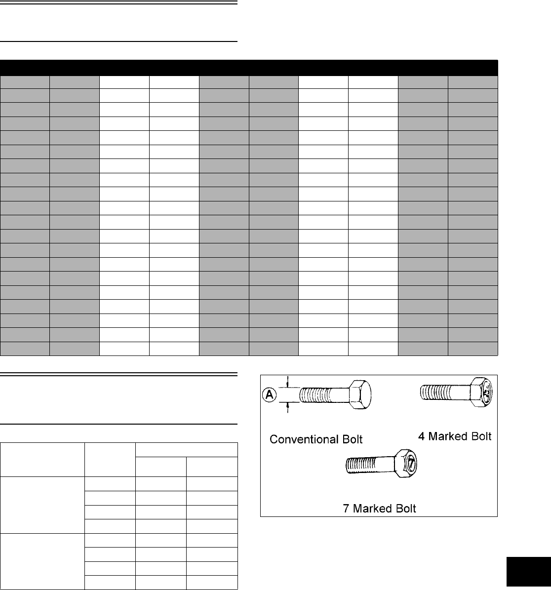
10-3
10
Torque Conversions
Tightening Torque
(General Bolts)
ft-lb kg-m ft-lb kg-m ft-lb kg-m ft-lb kg-m ft-lb kg-m
10.1212.941 5.7 61 8.4 81 11.2
20.3223.042 5.8 62 8.6 82 11.3
30.4233.243 5.8 63 8.7 83 11.5
40.6243.344 6.1 64 8.9 84 11.6
50.7253.545 6.2 65 9.0 85 11.8
60.8263.646 6.4 66 9.1 86 11.9
71.0273.747 6.5 67 9.3 87 12.0
81.1283.948 6.6 68 9.4 88 12.2
91.2294.049 6.8 69 9.5 89 12.3
10 1.4304.250 6.9 70 9.7 90 12.5
11 1.5314.351 7.1 71 9.8 91 12.6
12 1.7324.452 7.2 72 10.0 92 12.8
13 1.8334.653 7.3 73 10.1 93 12.9
14 1.9344.754 7.5 74 10.2 94 13.0
15 2.1354.855 7.6 75 10.4 95 13.1
16 2.2365.056 7.7 76 10.5 96 13.3
17 2.4375.157 7.9 77 10.7 97 13.4
18 2.5385.358 8.0 78 10.8 98 13.6
19 2.6395.459 8.2 79 10.9 99 13.7
20 2.8405.560 8.3 80 11.1 100 13.8
Type of Bolt
Thread
Diameter
A (mm)
Tightening Torque
kg-m ft-lb
(Conventional or
4 Marked Bolt)
5 0.2-0.4 1.5-3.0
6 0.4-0.7 3.0-5.0
8 1.0-1.6 7.0-11.5
10 2.2-3.5 16.0-25.5
(7 Marked Bolt) 5 0.3-0.6 2.0-4.5
6 0.8-1.2 6.0-8.5
8 1.8-2.8 13.0-20.0
10 4.0-6.0 29.0-43.5

11-1
11
SECTION 11 — TROUBLESHOOTING
TABLE OF
CONTENTS
Engine ………………….…………….…………….…………. 11-2
Drive………………….…………….…………….………….… 11-5
Fuel System ……….…………….………….…………….… 11-6
Electrical………….…………….…………….…………….… 11-7
Steering/Suspension ………….…………….……………. 11-9
Brakes ……………….………….…………….…………….. 11-10

11-2
Engine
Problem: Engine will not start or is hard to start (Compression too low)
Condition Remedy
1. Valve clearance out of adjustment 1. Adjust clearance
2. Valve guides worn — seated poorly 2. Repair — replace guides
3. Valves mistimed 3. Replace camshaft
4. Piston rings worn — broken 4. Replace rings
5. Cylinder bore worn 5. Replace — rebore cylinder
6. Starter motor cranks too slowly — does not
turn
6. See Electrical in this section
Problem: Engine will not start or is hard to start (No spark)
Condition Remedy
1. Spark plug fouled 1. Clean — replace plug
2. Spark plug wet 2. Clean — dry plug
3. Magneto defective 3. Replace magneto
4. CDI unit defective 4. Replace CDI unit
5. Ignition coil defective 5. Replace ignition coil
6. High-tension lead open — shorted 6. Replace high tension lead
Problem: Engine will not start or is hard to start (No fuel reaching the carburetor)
Condition Remedy
1. Gas tank vent hose obstructed 1. Clean vent hose
2. Carburetor inlet needle defective 2. Replace needle
3. Fuel hose obstructed 3. Clean — replace hose
4. Fuel screens obstructed 4. Clean — replace inlet screen — valve screen
5. Fuel pump defective 5. Replace fuel pump
Problem: Engine stalls easily
Condition Remedy
1. Spark plug fouled 1. Clean — replace plug
2. Magneto defective 2. Replace magneto
3. CDI unit defective 3. Replace CDI unit
4. Carburetor jets obstructed 4. Clean jets
5. Valve clearance out of adjustment 5. Adjust clearance
Problem: Engine noisy (Excessive valve chatter)
Condition Remedy
1. Valve clearance excessive 1. Adjust clearance
2. Valve spring(s) weak — broken 2. Replace spring(s)
3. Rocker arm — rocker arm shaft worn 3. Replace arm — shaft
4. Camshaft worn 4. Replace camshaft
Problem: Engine noisy (Noise seems to come from piston)
Condition Remedy
1. Piston — cylinder worn 1. Replace — service piston — cylinder
2. Combustion chamber carbon buildup 2. Clean chamber
3. Piston pin — piston pin bore worn 3. Replace — service pin — bore
4. Piston rings — ring groove(s) worn 4. Replace rings — piston

11-3
11
Problem: Engine noisy (Noise seems to come from timing chain)
Condition Remedy
1. Chain stretched 1. Replace chain
2. Sprockets worn 2. Replace sprockets
3. Tension adjuster malfunctioning 3. Repair — replace adjuster
Problem: Engine noisy (Noise seems to come from crankshaft)
Condition Remedy
1. Bearing worn — burned 1. Replace bearing
2. Lower rod-end bearing worn — burned 2. Replace bearing
3. Connecting rod side clearance too large 3. Replace thrust washer(s)
4. Centrifugal clutch loose 4. Tighten — replace clutch
5. Rotor/flywheel loose 5. Tighten — replace flywheel — crankshaft
Problem: Engine noisy (Noise seems to come from transmission)
Condition Remedy
1. Gears worn — rubbing 1. Replace gears
2. Splines worn 2. Replace shaft(s)
3. Primary gears worn — rubbing 3. Replace gears
4. Bearings worn 4. Replace bearings
5. Bushing worn 5. Replace bushing
Problem: Engine noisy (Noise seems to come from secondary bevel gear and final driven shaft)
Condition Remedy
1. Drive — driven bevel gears damaged — worn 1. Replace gears
2. Backlash excessive 2. Adjust backlash
3. Tooth contact improper 3. Adjust contact
4. Bearing damaged 4. Replace bearing
5. Gears worn — rubbing 5. Replace gears
6. Splines worn 6. Replace shaft(s)
7. Final driven shaft thrust clearance too large 7. Replace thrust washer(s)
Problem: Engine idles poorly
Condition Remedy
1. Valve clearance out of adjustment 1. Adjust clearance
2. Valve seating poor 2. Replace — service seats — valves
3. Valve guides defective 3. Replace guides
4. Rocker arms — arm shaft worn 4. Replace arms — shafts
5. Magneto defective 5. Replace magneto
6. CDI unit defective 6. Replace CDI unit
7. Spark plug fouled — gap too wide 7. Adjust gap — replace plug
8. Ignition coil defective 8. Replace ignition coil
9. Float out of adjustment 9. Adjust float height
10. Jets obstructed 10. Clean jets
11. Pilot screw setting improper 11. Adjust pilot screw

11-4
Problem: Engine runs poorly at high speed
Condition Remedy
1. High RPM “cut out” against RPM limiter 1. Shift into higher gear — decrease speed
2. Valve springs weak 2. Replace springs
3. Valve timing out of adjustment 3. Adjust timing
4. Cams — rocker arms worn 4. Replace cams — arms
5. Spark plug gap too narrow 5. Adjust gap
6. Ignition coil defective 6. Replace ignition oil
7. Float level too low 7. Adjust float height
8. Air cleaner element obstructed 8. Clean element
9. Fuel hose obstructed 9. Clean — prime hose
Problem: Exhaust smoke dirty or heavy
Condition Remedy
1. Oil (in the engine) overfilled — contaminated 1. Drain excess oil — replace oil
2. Piston rings — cylinder worn 2. Replace — service rings — cylinder
3. Valve guides worn 3. Replace guides
4. Cylinder wall scored — scuffed 4. Replace cylinder
5. Valve stems worn 5. Replace valves
6. Stem seals defective 6. Replace seals
Problem: Engine lacks power
Condition Remedy
1. Valve clearance incorrect 1. Adjust clearance
2. Valve springs weak 2. Replace springs
3. Valve timing out of adjustment 3. Time camshaft
4. Piston ring(s) — cylinder worn 4. Replace — service rings — cylinder
5. Valve seating poor 5. Repair seats
6. Spark plug fouled 6. Clean — replace plug
7. Rocker arms — shafts worn 7. Replace arms — shafts
8. Spark plug gap incorrect 8. Adjust gap — replace plug
9. Carburetor jets obstructed 9. Clean jets
10. Float level out of adjustment 10. Adjust float height
11. Air cleaner element obstructed 11. Clean element
12. Oil (in the engine) overfilled — contaminated 12. Drain excess oil — change oil
13. Intake manifold leaking air 13. Tighten — replace manifold
14. Cam chain worn 14. Replace cam chain — sprockets
Problem: Engine overheats
Condition Remedy
1. Carbon deposit (piston crown) excessive 1. Clean piston
2. Oil low 2. Add oil
3. Octane low — gasoline poor 3. Drain — replace gasoline
4. Oil pump defective 4. Replace pump
5. Oil circuit obstructed 5. Clean circuit
6. Gasoline level (in float chamber) too low 6. Adjust float height
7. Intake manifold leaking air 7. Tighten — replace manifold
8. Coolant level low 8. Fill — examine system for leaks
9. Fan malfunctioning 9. Check fan fuse — replace fan
10. Fan switch malfunctioning 10. Replace fan switch
11. Thermostat stuck — closed 11. Replace thermostat
12. Radiator hoses — cap damaged — obstructed 12. Clear obstruction — replace hoses

11-5
11
Drive
Problem: Power not transmitted from engine to wheels
Condition Remedy
1. Rear axle shaft serration worn — broken 1. Replace shaft
Problem: Power not transmitted from engine to either front wheel
Condition Remedy
1. Secondary drive — driven gear teeth broken 1. Replace gear(s)
2. Propeller shaft serration worn — broken 2. Replace shaft
3. Coupling damaged 3. Replace coupling
4. Coupling joint serration worn — damaged 4. Replace joint
5. Front drive — driven bevel gears broken —
damaged
5. Replace gear(s)
6. Front differential gears/pinions broken —
damaged
6. Replace gears — pinions
7. Front drive actuator not operating 7. Replace fuse — 2WD/4WD switch — front drive
actuator

11-6
Fuel System
Problem: Starting impaired
Condition Remedy
1. Starter jet obstructed 1. Clean jet
2. Starter jet passage obstructed 2. Clean passage
3. Starter body — carburetor leaking air 3. Tighten — adjust — replace gasket
4. Starter valve not operating properly 4. Check — adjust valve
Problem: Idling or low speed impaired
Condition Remedy
1. Slow jet obstructed — loose 1. Clean — tighten jet
2. Slow jet outlet obstructed 2. Clean outlet
3. Pilot screw setting incorrect 3. Adjust screw
4. Starter valve not fully closed 4. Adjust valve
5. Float height incorrect 5. Adjust float height
Problem: Medium or high speed impaired
Condition Remedy
1. High RPM “cut out” against RPM limiter 1. Shift into higher gear — decrease RPM speed
2. Main jet obstructed 2. Clean main jet
3. Needle jet obstructed 3. Clean needle jet
4. Throttle vacuum piston not operating
properly
4. Check piston operation
5. Filter obstructed 5. Clean filter
6. Float height incorrect 6. Adjust float height
7. Starter valve not fully closed 7. Adjust valve
Problem: Overflow and fuel level fluctuations
Condition Remedy
1. Float valve worn — damaged 1. Replace valve
2. Float valve spring broken 2. Replace spring
3. Float not working properly 3. Adjust float height — replace float
4. Float valve dirty 4. Clean valve
5. Float height too high — too low 5. Adjust float height

11-7
11
Electrical
Problem: Spark absent or weak
Condition Remedy
1. Ignition coil defective 1. Replace ignition coil
2. Spark plug defective 2. Replace plug
3. Magneto defective 3. Replace magneto
4. CDI unit defective 4. Replace CDI unit
5. Pick-up coil defective 5. Replace pick-up coil
Problem: Spark plug fouled with carbon
Condition Remedy
1. Mixture too rich 1. Adjust carburetor
2. Idling RPM too high 2. Adjust carburetor
3. Gasoline incorrect 3. Change to correct gasoline
4. Air cleaner element dirty 4. Clean element
5. Spark plug incorrect (too cold) 5. Replace plug
6. Valve seals cracked — missing 6. Replace seals
7. Oil rings worn — broken 7. Replace rings
Problem: Spark plug electrodes overheat or burn
Condition Remedy
1. Spark plug incorrect (too hot) 1. Replace plug
2. Engine overheats 2. Service cooling system
3. Spark plug loose 3. Tighten plug
4. Mixture too lean 4. Adjust carburetor
Problem: Battery does not charge
Condition Remedy
1. Lead wires/connections shorted — loose —
open
1. Repair — replace — tighten lead wires
2. Magneto coils shorted — grounded — open 2. Replace magneto coils
3. Regulator/rectifier shorted — punctured 3. Replace regulator/rectifier
Problem: Battery charges, but charging rate is below the specification
Condition Remedy
1. Lead wires shorted — open — loose (at
terminals)
1. Repair — tighten lead wires
2. Stator coils (magneto) grounded — open 2. Replace stator coils
3. Regulator/rectifier defective 3. Replace regulator/rectifier
4. Electrolyte low 4. Add distilled water
5. Cell plates (battery) defective 5. Replace battery

11-8
Problem: Magneto overcharges
Condition Remedy
1. Internal battery short circuited 1. Replace battery
2. Regulator/rectifier resistor damaged —
defective
2. Replace resistor
3. Regulator/rectifier poorly grounded 3. Clean — tighten ground connection
Problem: Charging unstable
Condition Remedy
1. Lead wire intermittently shorting 1. Replace lead wire
2. Magneto internally shorted 2. Replace magneto
3. Regulator/rectifier defective 3. Replace regulator/rectifier
Problem: Starter button not effective
Condition Remedy
1. Battery charge low 1. Recharge — replace battery
2. Switch contacts defective 2. Replace switch
3. Starter motor brushes not seating 3. Repair — replace brushes
4. Starter relay defective 4. Replace relay
5. Emergency stop — ignition switch off 5. Turn on switches
6. Wiring connections loose — disconnected 6. Connect — tighten — repair connections
Problem: Battery “sulfation” (Acidic white powdery substance or spots on surfaces of cell
plates)
Condition Remedy
1. Charging rate too low — too high 1. Replace battery
2. Battery electrolyte excessive — insufficient 2. Keep electrolyte to prescribed level
3. Specific gravity too high — too low 3. Charge battery — add distilled water
4. Battery run-down — damaged 4. Replace battery
5. Electrolyte contaminated 5. Recharge — replace battery
Problem: Battery discharges too rapidly
Condition Remedy
1. Electrolyte contaminated 1. Replace battery
2. Specific gravity too high 2. Charge battery — add distilled water
3. Charging system (charging operation) not
set properly
3. Check magneto — regulator/rectifier — circuit
connections — adjust for specified charging
operation
4. Cell plates overcharged — damaged 4. Replace battery — correct charging system
5. Battery short-circuited 5. Replace battery
6. Specific gravity too low 6. Recharge battery
Problem: Battery polarity reversed
Condition Remedy
1. Battery incorrectly connected 1. Reverse connections — replace battery

11-9
11
Steering/Suspension
Problem: Handling too heavy or stiff
Condition Remedy
1. Front wheel alignment incorrect 1. Adjust alignment
2. Lubrication inadequate 2. Lubricate appropriate components
3. Tire inflation pressure incorrect 3. Adjust pressure
4. Tie rod ends seizing 4. Replace tie rod ends
5. Linkage connections seizing 5. Repair — replace connections
Problem: Steering oscillation
Condition Remedy
1. Tires inflated unequally 1. Adjust pressure
2. Wheel(s) wobbly 2. Replace wheel(s)
3. Wheel hub cap screw(s) loose — missing 3. Tighten — replace cap screws
4. Wheel hub bearing worn — damaged 4. Replace bearing
5. Tie rod ends worn — loose 5. Replace — tighten tie rod ends
6. Tires defective — incorrect 6. Replace tires
7. A-arm bushings damaged 7. Replace bushings
8. Bolts — nuts (frame) loose 8. Tighten bolts — nuts
Problem: Steering pulling to one side
Condition Remedy
1. Tires inflated unequally 1. Adjust pressure
2. Front wheel alignment incorrect 2. Adjust alignment
3. Wheel hub bearings worn — broken 3. Replace bearings
4. Frame distorted 4. Repair — replace frame
5. Shock absorber defective 5. Replace shock absorber
Problem: Steering impaired
Condition Remedy
1. Tire pressure too high 1. Adjust pressure
2. Steering linkage connections worn 2. Replace connections
3. Cap screws (suspension system) loose 3. Tighten cap screws
Problem: Tire wear rapid or uneven
Condition Remedy
1. Wheel hub bearings worn — loose 1. Replace bearings
2. Front wheel alignment incorrect 2. Adjust alignment
Problem: Steering noise
Condition Remedy
1. Caps screws — nuts loose 1. Tighten cap screws — nuts
2. Wheel hub bearings broken — damaged 2. Replace bearings
3. Lubrication inadequate 3. Lubricate appropriate components

11-10
Brakes
Problem: Suspension too soft
Condition Remedy
1. Spring(s) weak 1. Replace spring(s)
2. Shock absorber damaged 2. Replace shock absorber
Problem: Suspension too stiff
Condition Remedy
1. A-arm-related bushings worn 1. Replace bushing
Problem: Suspension noisy
Condition Remedy
1. Cap screws (suspension system) loose 1. Tighten cap screws
2. A-arm-related bushings worn 2. Replace bushings
Problem: Rear wheel oscillation
Condition Remedy
1. Rear wheel hub bearings worn — loose 1. Replace bearings
2. Tires defective — incorrect 2. Replace tires
3. Wheel rim distorted 3. Replace rim
4. Wheel hub cap screws loose 4. Tighten cap screws
5. Parking brake adjusted incorrectly 5. Adjust parking brake
6. Rear suspension arm-related bushing worn 6. Replace bushing
7. Rear shock absorber damaged 7. Replace shock absorber
8. Rear suspension arm nut loose 8. Tighten nut
Problem: Braking poor
Condition Remedy
1. Pad worn 1. Replace pads
2. Pedal free-play excessive 2. Adjust free-play
3. Brake fluid leaking 3. Repair — replace hydraulic system
4. Hydraulic system leaking air 4. Bleed hydraulic system
5. Master cylinder/brake cylinder seal worn 5. Replace seal(s)
Problem: Brake pedal travel excessive
Condition Remedy
1. Hydraulic system entrapped air 1. Bleed hydraulic system
2. Brake fluid low 2. Add fluid to proper level
3. Brake fluid incorrect 3. Replace with correct fluid
4. Piston seal — cup worn 4. Replace seal — cup
Problem: Brake fluid leaking
Condition Remedy
1. Connection joints loose 1. Tighten joint
2. Hose cracked 2. Replace hose
3. Piston seal worn 3. Replace seal
|
Title |
File Size |
Download Links |
|
2002 Arctic Cat All Model ATV Service Manual.pdf |
231.7Mb |
Download |
|
2004 Arctic Cat 650 Service Manual.pdf |
25.1Mb |
Download |
|
2006 Arctic Cat ATV All Models Repair Manual.pdf |
146Mb |
Download |
|
2006 Arctic Cat ATV 250 Service Manual.pdf |
32.9Mb |
Download |
|
2006 Arctic Cat Y-6/Y-12 Youth ATV Service Manual.pdf |
50.9Mb |
Download |
|
2007 Arctic Cat Atv All Models Service Repair Manual.pdf |
126.4Mb |
Download |
|
2008 Arctic Cat 366 ATV Service Manual.pdf |
44.1Mb |
Download |
|
2008 Arctic Cat Prowler Xt Xtx Service Manual.pdf |
47.3Mb |
Download |
|
2008 Arctic Cat PROWLER XT/ PROWLER XTX Service Manual.pdf |
24.6Mb |
Download |
|
2008 Arctic Cat Thundercat 08 ATV Service Manual.pdf |
55Mb |
Download |
|
2009 Arctic Cat 150 Service Manual.pdf |
30Mb |
Download |
|
2010 Arctic Cat 450 H1, 700 H1, 550 H1, 1000 H2 mud pro, Thundercat Operator’s Manual.pdf |
4Mb |
Download |
|
2010 Arctic Cat Cat 700 Diesel SD Service Manual.pdf |
63.1Mb |
Download |
|
2011 Arctic Cat 400TRV Service Manual.pdf |
45.9Mb |
Download |
|
2011 Arctic Cat 700 PS EFT, 700 TRV PS EFT, 550 EFT, 550 PS EFT, 550 TRV EFT Operator’s Manual.pdf |
5.9Mb |
Download |
|
2012 Arctic Cat 350 HS / 425 HS Operator’s Manual.pdf |
3.3Mb |
Download |
|
2012 Arctic Cat 350 Service Manual.pdf |
38.3Mb |
Download |
|
2012 Arctic Cat DVX 90 Service Manual.pdf |
35.1Mb |
Download |
|
2012 Arctic Cat DVX 90, 1000 I MUD PRO, 450 I TRV/GT, 550 I TRV/GT, 550 I CRUISER, 700 I TRV/GT, 1000 I TRV/GT, 350 FIS Operator’s Manual.pdf |
21.4Mb |
Download |
|
2012 Arctic Cat XC 450i ATV Service Manual.pdf |
36.4Mb |
Download |
|
2014 Arctic Cat 450 Service Manual.pdf |
33.7Mb |
Download |
|
2015 Arctic Cat PROWLER HDX Service Manual.pdf |
13.2Mb |
Download |
|
2015 Arctic Cat XR 500б Xr 700, Xr 550 Operator’s Manual.pdf |
1.8Mb |
Download |
|
2016 Arctic Cat Alterra 500 Service Manual.pdf |
55.5Mb |
Download |
|
2017 Arctic Cat VLX 7000 Service Manual.pdf |
37.6Mb |
Download |
|
Arctic Cat 450/1000 Service Manual.pdf |
61.9Mb |
Download |
|
Arctic Cat 500, 700, 1000, 700 MUD PRO, 700 TBX, 1000 MUD PRO, 550 Operator’s Manual.pdf |
3.8Mb |
Download |
|
Arctic Cat ATV Electrical & Batteries.pdf |
6.1Mb |
Download |
|
2001 |
Arctic Cat . 2001 models
Guide for repairs and maintenance ( the Service manual ) in English. Format: PDF, Size: |
|
2002 |
Arctic Cat . 2002 models
Repair and maintenance manual ( the Service manual ) in English. Format: PDF, Size: |
|
2006 |
Arctic Cat DVX 400.
Repair and maintenance manual ( the Service manual ) in English. Format: PDF, Size: |
|
Arctic Cat Y6 / Y12.
Repair and maintenance manual ( the Service manual ) in English. Format: PDF, Size: |
|
|
2007 |
Arctic Cat Prowler / XT.
Repair and maintenance manual ( the Service manual ) in English. Format: PDF, Size: |
|
2008 |
Arctic Cat 366.
Repair and maintenance manual ( the Service manual ) in English. Format: PDF, Size: |
|
Arctic Cat Y6.
Repair and maintenance manual ( the Service manual ) in English. Format: PDF, Size: |
|
|
2009 |
Arctic Cat Prowler XTZ.
Repair and maintenance manual ( the Service manual ) in English. Format: PDF, Size: |
|
2010 |
Arctic Cat 150.
Repair and maintenance manual ( the Service manual ) in English. Format: PDF, Size: |
|
Arctic Cat 450.
Repair and maintenance manual ( the Service manual ) in English. Format: PDF, Size: |
|
|
2011 |
Arctic Cat 350/425.
Repair and maintenance manual ( the Service manual ) in English. Format: PDF, Size: |
|
Arctic Cat 366/450/550/650/700/450 TRV / 550 TRV / 700 TRV / 700 Cruiser / 1000 Cruiser / 700 Mud Pro / 700 TBX / 1000 The instruction manual is in Russian. Format: PDF, Size: 4.6 Mb . |
|
|
Arctic Cat 450 TRV / 550 TRV / 700 TRV / 700 Cruiser / 1000 Cruiser.
Guide Operation ( Operator`s manual ) (User Guide) in English. Format: PDF, Size: |
|
|
Arctic Cat 700 Diesel SD.
Repair and maintenance manual ( the Service manual ) in English. Format: PDF, Size: |
|
|
2012 |
Arctic Cat XC 450i.
Repair and maintenance manual ( the Service manual ) in English. Format: PDF, Size: |
|
2014 |
Arctic Cat Prowler HDX.
Repair and maintenance manual ( the Service manual ) in English. Format: PDF, Size: |
|
Arctic Cat XC 450.
Repair and maintenance manual ( the Service manual ) in English. Format: PDF, Size: |
Arctic Cat ATVs have long been a success with amateurs and professionals due to their brilliant technical characteristics, excellent design and most importantly — the highest
reliability.
The company’s products have earned the status of all-terrain vehicles for excellent cross-country ability even in the most adverse terrain, and achieved without compromising maneuverability and
other properties.
The company Arctic Cat (USA) began operations for more than half a century ago — in 1960.
Such a long presence in the global market helps to maintain a leading position.
Constantly developing production, improving snowmobiles and ATVs, releasing new, all the best models and adhering to a winning pricing policy.
The main advantages (advantages) of the Arctic Cat ATVs:
- lowered center of gravity, providing all-terrain and preventing overturning;
- high ground clearance;
- independent suspension;
- low fuel consumption;
- Great ergonomics combined with great design.
By the way, the reliable partner powerful motor vehicles Arctic Cat supplies the famous partner — the Japanese brand Suzuki.
ATVs of this company are bought even by the Pentagon — for use in the US Army. They are also supplied to the Finnish border agency to patrol the border with Russia.

|
Detail Specifications: 1211/1211737-650_h1_2010.pdf file (18 Feb 2023) |
Accompanying Data:
Arctic Cat 650 H1 2010 Offroad Vehicle PDF Operator’s Manual (Updated: Saturday 18th of February 2023 10:38:49 PM)
Rating: 4.3 (rated by 83 users)
Compatible devices: 450 TRV, DVX 400 2004, 500 Sno Pro, 2010 400 H1 TRV, 2014 XC 450, 120 sno pro, 2016 Alterra 500, ZR 3000.
Recommended Documentation:
Text Version of Operator’s Manual
(Ocr-Read Summary of Contents, UPD: 18 February 2023)
-
52, Arctic Cat 650 H1 2010 50 Headlight HI/LO Switch CF245A Use the headlight HI/LO switch to select the high or low headlight beam when the ignition switch is in the LIGHTS position. When the switch is in the HI position, the high beam will illuminate. When the switch is in the LO position, the low beam will illumi- nate. Emergency Stop Switch OFF position — The ignition circuit is off. The engine …
-
57, Arctic Cat 650 H1 2010 55 GENERAL INFORMATION SAFETY FLAG BRACKET A bracket is provided for mounting a flag at the rear of the ATV. RACK LOADING (Front and Rear) The front rack and rear rack are designed to carry specified load capaci- ties. Always refer to the ATV Load Capacity Ratings Chart for proper capacities. TRAILERING AND TOWING Arctic Cat ATV’s are equipped with a frame-mounted receiver for a s…
-
69, 67 GENERAL MAINTENANCE CF125A 1. Inspect all drive axle boots for cracks, tears, or perforations. 2. If boot damage is present, contact an authorized Arctic Cat ATV dealer for service. BATTERY The battery is located under the seat. After being in service, batteries require regular cleaning and recharging in order to deliver peak performance and maximum service life. T…
-
85, 83 CHANGE OF ADDRESS, OWNERSHIP, OR WARRANTY TRANSFER Arctic Cat Inc. keeps on file the current name and address of the owner of this ATV. This will allow Arctic Cat to reach the current owner with any important safety information which may be necessary to protect customers from personal injury or property damage. Please make sure a copy of this form is completed and returned to Arctic Cat…
-
39, Arctic Cat 650 H1 2010 ATV OPERATION 37 NOTE: The high range is for nor- mal riding with light loads. The low range is for carrying heavy loads or trailer towing. Compared to HIGH range, the LOW range posi- tion provides slower speed and greater torque to the wheels. 3. To engage reverse gear from neu- tral, move the shift lever outward and rearward into the R position. Braking/Stopping Always all…
-
48, 46 4. Practice driving in an open snow- covered or ice-covered area at slow speeds before driving on snow-covered or ice-covered trails. 5. Learn how the ATV responds to steering and braking on the type of terrain to be encountered on the ride. Stopping The ATV To stop the ATV, first release the throt- tle lever. Next, apply the brake. Stopping The Engine To stop the engine, tur…
-
44, 42 ATV-205 1. Shift your body weight as far back on the seat as possible. 2. Keep it in a low gear; stay out of neutral. 3. Lightly apply the brake and ease up on the throttle. Sidehilling/Traversing Sidehilling is considered an advanced skill; it’s really tricky and unpredict- able. So, whether your skills are advanced or not, try to avoid this kind of riding. If you’re in a situa…
-
79, 77 GENERAL MAINTENANCE ATV-1097 The storage compartment is above the engine in front of the seat. AL675
… -
63, 61 GENERAL MAINTENANCE LIQUID COOLING SYSTEM NOTE: Debris in front of the engine or packed between the cooling fins of the radiator can reduce cooling capability. Using a garden hose, wash the radiator to remove any debris preventing air flow. The cooling system capacity can be found in the specification chart. The cooling system should be inspected daily for leakage and damage. I…
-
32, ! WARNING Indicates a potential hazard that could result in a serious injury or death. 30 Supervision Overview You’re responsible for supervising those who ride your ATV. Your wisdom is valuable… it’ll bring them all back safely—your friends, your family, your relatives, and your ATV. It’s crucial that you consider yourself a supervisor for all riders of your ATV. Whether you acc…
Recommended Instructions:
Catalyst 6800, PLM-A55 — Glasstron — 0.7″ TFT Active Matrix Head Mounted Display, WL54AP, WY42


-
Arctic Cat Model 400/400-3in1/500/650-V2/650-H1-3in1 � …
400 3in1 80
-
This ATV should not be ridden by anyone under 16 years of age. Passenger under 12 are prohibited. CF1000AUCF800AU-2AOWNER’S MANUALREAD THIS MANUAL CAREFULLYIt contains important safety informationCFORCE 850XCCFORCE 1000 …
CFORCE 850XC 156
-
The vehicle pictured on the front cover may not match your vehicle.No part of this publication may be reproduced without writtenpermission.This publication includes the latest production information availablebefore printing. Honda Motor Co., Ltd. reserves the right to makechanges at any time without notice and without incurring any obligation.This manual sho …
TRX500FA 306
-
No one under the age of 16 should operate this vehicle.Provincial / Municipal governments have dierent regulations pertaining to owning and operating an o-road vehicle; learn the regulations in your area.READ THIS MANUAL CAREFULLYFor questions regarding this UTV, please contact HISUN at: (877) 838-6188 www.hisunmotors.comREV. 01231401 HS500 OWNER’S MANUAL …
HS 500 216
Additional Information:
Popular Right Now:
Operating Impressions, Questions and Answers:
FOREWORD
This Arctic Cat Service Manual contains service, maintenance, and troubleshooting information for certain 2008
Arctic Cat ATV models (see cover). The complete manual is designed to aid service personnel in service-oriented
applications.
Arctic Cat offers additional publications (when they become available) to aid in servicing other ATV models. To
service models not included in this manual, please refer to the following publications:
• 2008 Y-12 Service Manual
• 2008 DVX/Utility 250 Service Manual
• 2008 366 Service Manual
• 2008 DVX 400 Service Manual
• 2008 700 Diesel Service Manual
• 2008 Thundercat Service Manual
This manual is divided into sections. Each section covers a specific ATV component or system and, in addition to
the standard service procedures, includes disassembling, inspecting, and assembling instructions. When using this
manual as a guide, the technician should use discretion as to how much disassembly is needed to correct any given
condition.
The service technician should become familiar with the operation and construction of each component or system
by carefully studying the complete manual. This manual will assist the service technician in becoming more aware
of and efficient with servicing procedures. Such efficiency not only helps build consumer confidence but also saves
time and labor.
All Arctic Cat ATV publications and decals display the words Warning, Caution, Note, and At This Point to
emphasize important information. The symbol ! WARNING identifies personal safety-related information.
Be sure to follow the directive because it deals with the possibility of severe personal injury or even death. The
symbol ! CAUTION identifies unsafe practices which may result in ATV-related damage. Follow the direc-
tive because it deals with the possibility of damaging part or parts of the ATV. The symbol NOTE: identifies
supplementary information worthy of particular attention. The symbol
AT THIS POINT directs the tech-
nician to certain and specific procedures to promote efficiency and to improve clarity.
At the time of publication, all information, photographs, and illustrations were technically correct. Some photo-
graphs used in this manual are used for clarity purposes only and are not designed to depict actual conditions.
Because Arctic Cat Inc. constantly refines and improves its products, no retroactive obligation is incurred.
All materials and specifications are subject to change without notice.
Keep this manual accessible in the shop area for reference.
Product Service and
Warranty Department
Arctic Cat Inc.
© 2007 Arctic Cat Inc. July 2007
®™ Trademarks of Arctic Cat Inc., Thief River Falls, MN 56701
Back to TOC
FOR ARCTIC CAT ATV DISCOUNT PARTS CALL 606-678-9623 OR 606-561-4983
www.mymowerparts.com