Ariston
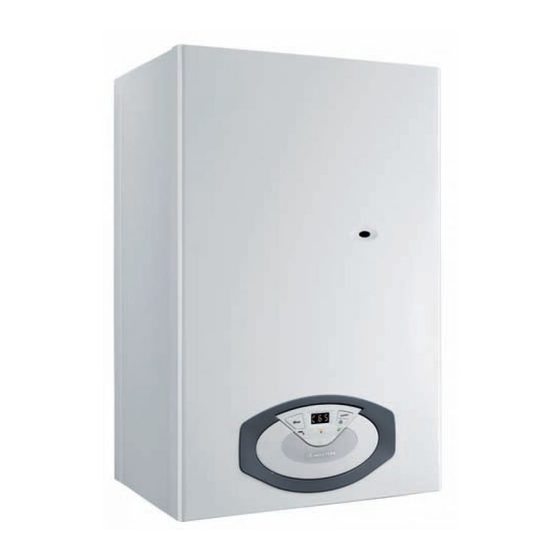
Газовые настенные котлы Ariston серии CLAS 24 FF, CLAS 28 FF, CLAS 24 CF. Инструкция по эксплуатации.
Скачать
Pdf 661.98 Kb
Язык: RU, RO

HK#K9H — Руководство по эксплуатации
8A6H ‘)$’-
9B7I(*<<
9B7I(.<<
9B7I(*9<
Руководство по эксплуатации
Мы хотим поблагодарить Вас за сделанный Вами выбор – приобретение
Правила безопасности
котла нашего производства. Мы уверены, что предоставили Вам
технически совершенную продукцию.
Перечень условных обозначений:
Данное руководство содержит указания и рекомендации в части
монтажа, правильной эксплуатации и технического обслуживания котла.
Несоблюдение этого предупреждения может привести
Внимательно изучите руководство и храните его в доступном месте. Наши
к несчастным случаям, в определенных ситуациях даже
Авторизованные Сервисные Центры всегда в Вашем распоряжении. С
смертельным.
наилучшими пожеланиями, компания «Мерлони ТермоСанитари СпА»
Настоящее руководство по эксплуатации является неотъемлемой
Несоблюдение этого предупреждения может привести к
частью комплекта поставки котла. Пользователь должен хранить его
повреждениям, в определенных ситуациях даже серьезным,
в доступном месте вблизи котла, в том числе в случае передачи котла
имущества, домашних растений и нанести ущерб
другому владельцу или пользователю и/или при установке котла в
домашним животным.
другом месте.
Внимательно ознакомьтесь с указаниями и предупреждениями,
Не производите никаких действий, для которых требуется
открыть агрегат.
содержащимися в руководстве по эксплуатации, так как в них приводятся
Удар током — компонеты под напряжением
важные правила по технике безопасности при монтаже, эксплуатации и
Опасность ожегов и порезов – горячие компоненты и
техническом обслуживании изделия.
острые выступы и края.
Данный котел предназначен для отопления помещений и приготовления
горячей воды для хозяйственно-бытовых нужд.
Не производите никаких действий, для которых требуется
демонтировать агрегат.
Удар током — компонеты под напряжением.
Затопление – утечка воды из отсоединенных труб.
ГАРАНТИЯ
Взрыв, пожар или отравление газом в случае его утечки
ГАРАНТИЯ НА ДАННОЕ ОБОРУДОВАНИЕ ВСТУПАЕТ В СИЛУ С МОМЕНТА
из поврежденного газопровода.
ПЕРВОГО ПУСКА, О ЧЕМ В ГАРАНТИЙНОМ ТАЛОНЕ ОБЯЗАТЕЛЬНО ДЕЛАЕТСЯ
СООТВЕТСТВУЮЩАЯ ОТМЕТКА.
Бережно обращаться с проводом электропитания.
Удар током – оголенные провода под напряжением
ПЕРВЫЙ ПУСК ДОЛЖЕН ОСУЩЕСТВЛЯТЬСЯ СПЕЦИАЛИЗИРОВАННОЙ
ОРГАНИЗАЦИЕЙ В СООТВЕТСТВИИ С ТРЕБОВАНИЯМИ ГАРАНТИЙНОГО
Не оставляйте посторонние предметы на агрегате.
Несчастные случаи — падение предметов из-за вибраций
ТАЛОНА И ИНСТРУКЦИЙ ПРОИЗВОДИТЕЛЯ.
агрегата.
Повреждение агрегата или находящихся снизу предметов
по причине падения предметов из-за вибраций агрегата.
Котел следует подключить к контурам отопления и горячего
Не залезайте на агрегат.
водоснабжения (ГВС), которые должны соответствовать техническим
Опасность падения с агрегата.
характеристикам котла.
Повреждение агрегата или находящихся снизу предметов
Строго запрещается использовать котел в целях, не указанных в
по причине падения агрегата из-за отсоединения
данной инструкции. Производитель не несет ответственности за
креплений.
повреждения, являющиеся следствием ненадлежащей эксплуатации
Не поднимайтесь на стулья, табуретки, лестницы или
котла или несоблюдения требований данной инструкции.
нестабильные приспособления для чистки агрегата.
Монтаж, техническое обслуживание и другие работы с котлом должны
Падение или защемление (раскладные лестницы).
проводиться в полном соответствии с требованиями нормативных
документов и инструкций производителя.
Производите чистку агрегата только после его отключения,
В случае неисправности и/или нарушения нормальной
повернув внешний разъединитель в положение OFF (ВЫКЛ.).
Удар током — компонеты под напряжением.
работы отключите котел, закройте газовый кран и вызовите
квалифицированного специалиста. Запрещается выполнять ремонт
Для чистки агрегата не используйте растворители, агрессивные
котла самостоятельно. Все ремонтные работы, должны проводиться
моющие средства или инсектициды.
квалифицированными специалистами, только с использованием
Повреждение пластмассовых или покрашенных деталей.
оригинальных запасных частей. ПРИ НЕСОБЛЮДЕНИИ ТРЕБОВАНИЙ
ДАННОЙ ИНСТРУКЦИИ СУЩЕСТВЕННО СНИЖАЕТСЯ БЕЗОПАСНОСТЬ
Не используйте агрегат в целях, отличных от его использования
ЭКСПЛУАТАЦИИ КОТЛА И АННУЛИРУЮТСЯ ГАРАНТИЙНЫЕ
для нормальных бытовых нужд.
ОБЯЗАТЕЛЬСТВА ПРОИЗВОДИТЕЛЯ.
Повреждение агрегата из-за его перегрузки.
При проведении технического обслуживания или любых работ в
Повреждение предметов из-за неправильного
непосредственной близости от воздуховодов, дымоходов или их
обращения.
принадлежностей, следует отключить котел и закрыть газовый кран.
Не допускайте к использованию агрегата детей или неопытных
После завершения всех работ, проверьте эффективность
лиц.
функционирования воздуховодов и дымоходов. В случае длительного
Повреждение агрегата по причине его неправильного
перерыва в эксплуатации котла необходимо:
использования.
• отключить электропитание котла, установив внешний
В случае появления запаха горелого или дыма из агрегата
двухполюсный выключатель в положение «ВЫКЛ»;
отключите электропитание, перекройте основной газовый
• перекрыть газовый кран, краны системы отопления и ГВС;
кран, откройте окна и вызовите техника.
• если существует вероятность замерзания, то следует слить воду
Ожеги, отравление токсичными газами.
из контура отопления и ГВС.
При окончательном отключении котла поручите эту операцию
В случае появления запаха газа перекройте основной газовый
кран, откройте окна и вызовите техника.
квалифицированному специалисту.
Взрыв, пожар или отравление токсичными газами.
При чистке котла следует отключить и перевести двухполюсный
выключатель в положение «OFF» (ВЫКЛ). Чистку следует проводить
с помощью ткани, смоченной в мыльной воде. Не используйте
агрессивные моющие средства, инсектициды или другие токсичные
вещества. Не используйте и не храните легковоспламеняющиеся
вещества в помещении, в котором установлен котел.
2
Руководство по эксплуатации
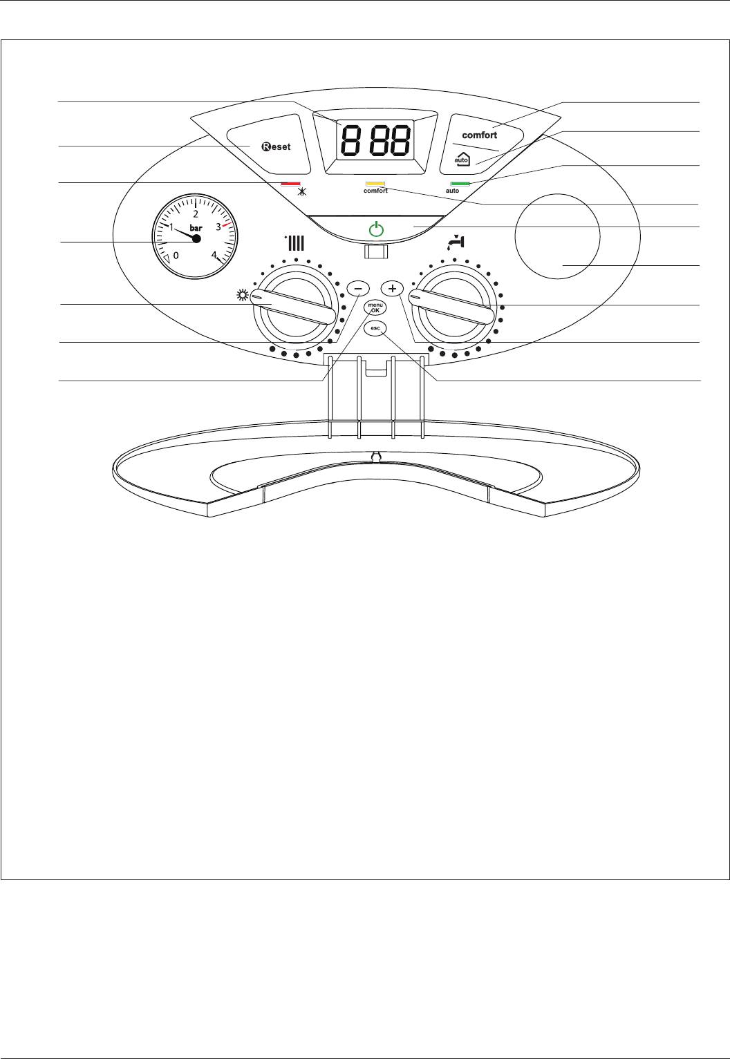
Панель управления
1
16
15
2
14
3
13
12
4
11
5
10
6
9
7
8
Обозначения
1. Дисплей
2. Кнопка RESET (сброс)
3. Красный световой индикатор (аварийная остановка)
4. Манометр (давление в контуре отопления)
5. Рукоятка переключения режимов работы (отопление —
ГВС) и регулировки температуры в контуре отопления
6. Кнопка управления «–»
7. Кнопка MENU/OK (МЕНЮ/ВВОД – кнопка настройки
параметров и программирования)
8. Кнопка ESC (отмена)
9. Кнопка управления «+»
10. Регулятор температуры воды в контуре ГВС
11. Таймер-программатор (дополнительно)
12. Кнопка ON/OFF (ВКЛ/ВЫКЛ)
13. Световой индикатор режима «Комфорт»
14. Зелёный световой индикатор (режим «AUTO» включен)
15. Кнопка AUTO (автоматический режим)
16. Кнопка COMFORT (функция «Комфорт»)
3
Руководство по эксплуатации
ВНИМАНИЕ!
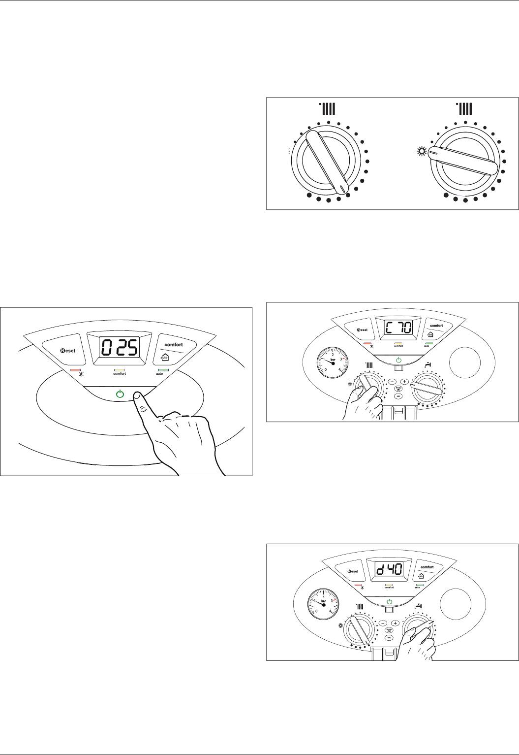
Зимний и летний рабочие режимы
Монтаж, ввод в эксплуатацию, регулировки и техническое
В рабочем режиме «зима» (winter) котел используется как для
обслуживание должен выполнять квалифицированный
отопления, так и для ГВС. В режиме «лето» (summer) котел
специалист согласно действующим нормам и правилам.
используется только для ГВС.
Неправильный монтаж котла может привести к травмам людей и
Для выбора режима «зима» или «лето» служит рукоятка на
животных и вызвать повреждение имущества. За неправильный
панели управления. Положение «O» рукоятки «5» соответствует
монтаж котла изготовитель ответственности не несет.
режиму «лето». Положение рукоятки между минимальным и
максимальным делениями шкалы соответствует режиму «зима».
Первый пуск
JПри установке котла внутри помещения убедитесь, что
соблюдаются все условия, связанные с поступлением воздуха
в помещение и его вентиляцией, предписанные действующим
законодательством.
Регулярно проверяйте давление воды на панели управления и
следите, чтобы в холодной системе оно находилось в диапазоне
от 0,6 до 1,5 бар. Если давление упадет ниже минимального
значения, то на дисплее появится индикатор подпитки контура
отопления.
Если давление незначительно меньше минимально допустимого,
для восстановления давления откройте кран в нижней части котла.
Если давление слишком часто падает, значит, в системе имеется
Регулировка температуры контура отопления
утечка. В этом случае следует вызвать квалифицированного
Для регулирования температуры в контуре отопления
специалиста для ее устранения.
предназначена рукоятка «5». При положении её указателя между
1 и 6 температура регулируется в пределах от 38 °С до примерно
Включение
82 °С.
Чтобы включить котел, нажмите кнопку «ON/OFF» (ВКЛ/ВЫКЛ) на
На дисплее отображается температура воды в контуре
панели управления. На дисплее отображается:
отопления.
Регулировка температуры контура ГВС
Регулировка температуры воды в контуре ГВС с помощью
рукоятки «10» возможна как в зимнем, так и в летнем рабочих
режимах. Регулировка температуры ГВС возможна в пределах
от 36 °С до примерно 56 °С, в зависимости от расхода воды и
положения рукоятки между минимальным и максимальным
делениями шкалы.
Первая цифра указывает рабочий режим:
Чтобы увеличить температуру воды, поверните рукоятку «10» на
0 XX — Режим ожидания
максимум и уменьшите разбор.
C XX — Отопление
На дисплее отображается температура воды в контуре ГВС.
C XX— Задержка отключения насоса в режиме отопления
d XX — Горячее водоснабжение (ГВС)
H XX — Задержка отключения насоса в режиме ГВС
F XX — Включен циркуляционный насос в режиме защиты от
замерзания
— Включена горелка в режиме защиты от замерзания
Второй и третий индикаторы отображают:
• температуру воды при отсутствии запроса на отопление;
• температуру воды в контуре отопления;
• температуру воды в контуре ГВС;
• температуру воды в режиме защиты от замерзания.
4
Руководство по эксплуатации
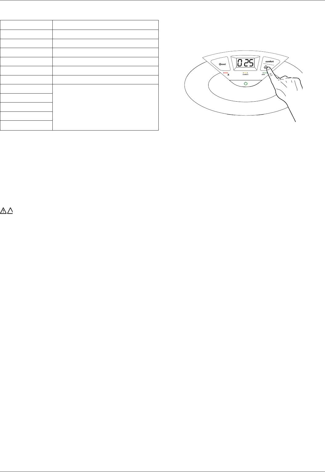
Функция «Комфорт»
Условия автоматического отключения котла
Функция «Комфорт» обеспечивает максимальное удобство и
Для защиты котла от повреждения предусмотрены проверки,
комфорт при работе котла в режиме ГВС, т.к. в этом режиме
осуществляемые электронным блоком управления. В случае
вторичный теплообменник поддерживается в нагретом
отклонения от нормального режима работы производится
состоянии при некоторой заданной температуре, даже когда
отключение. При защитном отключении на дисплей панели
разбора горячей воды нет; благодаря этому значительно
управления выводится код ошибки, указывающий тип и причину
сокращается время приготовления горячей воды.
отключения.
Чтобы включить этот режим, нажмите кнопку «COMFORT» на
Предусмотрены два типа отключения.
панели управления. Когда котел работает в режиме «Комфорт»,
светится желтый световой индикатор «13» на панели управления.
Отключение контура отопления
Чтобы отключить контур отопления, поверните рукоятку «5» в
положение «O». Работа контура ГВС по-прежнему возможна.
Отключение котла
Чтобы отключить котел, нажмите кнопку «ON/OFF» (ВКЛ/ВЫКЛ)
на панели управления. При этом отключается и дисплей.
Для полного отключения котла переведите внешний
двухполюсный выключатель в положение «OFF» (ВЫКЛ).
Перекройте газовый кран.
5
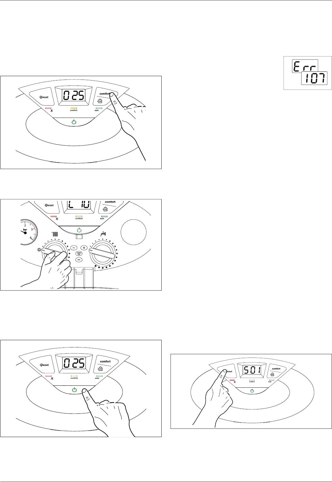
Защитное отключение
Защитное отключение
Осуществляется в случае отклонения от
нормальной работы, которое может быть
устранено без вмешательства специалиста.
В этом случае котел автоматически
включается повторно, как только причина
отключения устранена. На дисплее мигает
«Err» (Ошибка) и код ошибки (например, Err
107).
После устранения причины отключения котел возобновляет
нормальное функционирование. При защитном отключении
можно попытаться восстановить работу котла путём его
отключения и повторного включения кнопкой «ON/OFF» на
панели управления.
Если после этого на дисплее котла по-прежнему остаётся символ
защитного отключения, отключите котел. Для этого переведите
внешний двухполюсный выключатель в положение «OFF» (ВЫКЛ),
перекройте газовый кран и обратитесь к квалифицированному
специалисту.
Защитное отключение из-за низкого давления воды
При недостаточном давлении воды в контуре отопления котел
производит защитное отключение.
На дисплее мигает «Err» (Ошибка) и код ошибки при недостаточной
циркуляции – 10, или 104, или 105, или 106, или 107 (Err 107).
Проверьте давление воды по показаниям манометра на панели
управления; при холодной системе значение должно быть от 0,6
до 1,5 бар.
Если давление незначительно меньше минимального допус тимого,
для восстановления давления откройте кран в нижней части
котла. Если давление падает часто, возможно, в системе имеется
утечка. Обратитесь к специалисту для ее уcтранения.
Аварийная остановка
Относится к случаям, когда неисправность не может быть
устранена автоматически. На дисплее мигает «Err» (Ошибка), код
ошибки и светится красный световой индикатор « ». Котел в этом
случае не перезапускается автоматически, но, возможно, может
быть перезапущен после нажатия кнопки « ». Если несколько
попыток перезапуска не дают желаемого результата, обратитесь
к специалисту.
ВНИМАНИЕ!
В СЛУЧАЕ ЧАСТЫХ ОСТАНОВОК ОБРАТИТЕСЬ В АВТОРИЗОВАННЫЙ ЦЕНТР
ТЕХНИЧЕСКОГО ОБСЛУЖИВАНИЯ. ПО СООБРАЖЕНИЯМ БЕЗОПАСНОСТИ
РАЗРЕШЕНО В ТЕЧЕНИЕ 15 МИН ВЫПОЛНЯТЬ НЕ БОЛЕЕ ПЯТИ ОПЕРАЦИЙ
СБРОСА (НАЖАТИЙ НА КНОПКУ ). ЕСЛИ ОСТАНОВКА ИМЕЕТ МЕСТО НЕ
СИСТЕМАТИЧЕСКИ ИЛИ ОДНОКРАТНО, ОБРАЩАТЬСЯ В СЕРВИСНЫЙ ЦЕНТР
НЕ ОБЯЗАТЕЛЬНО.
Руководство по эксплуатации
Таблица кодов неисправностей
Функция AUTO – автоматический режим работы
При подключенных дополнительных устройствах, в режиме AUTO
мощность котла и температура в контуре отопления регулируется
Дисплей Описание
в зависимости от внешних условий, таких, как температура на
1 01 Перегрев
улице и температура в помещении.
5 01 Нет пламени
6 01 Zásah spalinové sondy
3 05 Неисправность платы управления
3 06 Неисправность платы управления
3 07 Неисправность платы управления
1 03
1 04
1 05
Недостаточная циркуляция
1 06
1 07
Комфортная температура в помещении при этом достигается
максимально быстро, при экономии энергопотребления и
Временная блокировка из-за аномального дымоудаления
максимальном к.п.д., благодаря чему также снижается износ
(24 CF) 6 01
элементов котла и увеличивается срок службы.
Это защитное устройство блокирует водонагревательную колонку
Обычно котлы такого типа настроены пользователем на высокую
в случае неисправности в системе дымоудаления. Блокировка
температуру в контуре отопления (70–80 °C), с целью обеспечения
агрегата является временной и показывается кодом сбоя 6 01.
эффективной работы в зимний период при низкой температуре
По прошествии 12 минут колонка перейдет в режим включения.
на улице. Однако такая температура в контуре отопления, как
Если неисправность системы дымоудаления была устранена,
правило, сохраняется и в менее холодные дни, более типичные для
колонка переходит в рабочий режим, в противном случае она
осенне-зимнего периода. Это приводит к перегреву помещения,
вновь блокируется и повторяет вышеописанный цикл.
даже если в нём имеется термостат, контакты которого при этом
размыкаются (т.е. нет запроса на отопление). Как следствие,
ВНИМАНИЕ!!
расходуется слишком много энергии, а условия в помещении
Если блокировка колонки повторяется часто,
далеки от комфортных.
необходимо вызвать техника из уполномоченного
Новый интеллектуальный режим AUTO управляет котлом и
Центра технического обслуживания для проверки
устанавливает оптимальный режим работы в зависимости от
исправности системы дымоудаления и вентиляции в
условий среды, внешних устройств, подключенных к котлу и
помещении.
требуемых рабочих параметров. В этом режиме котел постоянно
определяет, на каком уровне мощности и с какой температурой в
контуре отопления работать, по температуре на улице и заданной
Защита от замерзания
температуре в помещении.
Режим защиты замерзания включается при наличии
электропитания по показаниям датчика температуры на подаче
контура отопления, независимо от остальных режимов и
Переход на другой тип газа
параметров.
Котлы рассчитаны на природный газ (метан) и сжиженный газ. Для
Если температура в первичном контуре опускается ниже 8 °C, то на
переключения обратитесь в Авторизованный Сервисный Центр.
несколько минут включается насос. Через две минуты циркуляции
(нерегулируемый параметр) котел проверяет следующее:
Техническое обслуживание
• Если температура на подаче контура отопления выше 8 °C, то
Обязательно осуществлять ежегодное техническое обслуживание
насос останавливается;
котла, которое должен осуществлять квалифицированный
• Если температура на подаче контура отопления между 4 и 8 °C,
персонал.
насос работает еще две минуты;
• Если температура на подаче контура отопления ниже 4 °C,
производится розжиг горелки (в режиме отопления) на
минимальной мощности; горелка работает, пока температура
не достигнет 33 °C, после чего отключается, а насос работает
еще две минуты.
Режим защиты от замерзания запускается (при нормальной
работе котла) только при соблюдении следующих условий:
• давление в системе нормальное;
• имеется электропитание котла (символ подсвечен);
• имеется подача газа.
6
-
Contents
-
Table of Contents
-
Bookmarks
Quick Links
Related Manuals for Ariston Clas 24 FF
Summary of Contents for Ariston Clas 24 FF
-
Page 2: Table Of Contents
INDEX General Information ………………..3 Maintenance ………………42 General Information …………………. 3 General comments ………………….42 Control Panel……………………4 Operational test ………………….42 Overall wiew ……………………5 Draining procedures ………………..42 Technical Information ………………..6 Draining the D.H.W. system and indirect cylinder ……….42 Draining the System ………………..43 Installation ………………..8 Completion ……………………43 Reference Standards …………………
-
Page 3: General Information
general information This manual is an integral and essential part of the product. It General Instructions should be kept with the appliance so that it can be consulted by the user and our authorised personnel. Read the instructions and recommendations in these Installation and Servicing Instructions carefully to ensure proper installation, Please carefully read the instructions and notices about the unit use and maintenance of the appliance.
-
Page 4: Control Panel
CLAS 24 FF CLAS 30 FF Fig. 1 Legend 10. Domestic Hot Water adjustment knob (COMBI models) Display 11. Time clock (optional) RESET button 12. ON/OFF Switch Red LED (illuminated = boiler lockout) 13. “COMFORT” Function L.E.D (COMBI models) Heating System Pressure Gauge Heating only L.E.D (SYSTEM models)
-
Page 5: Overall Wiew
general information Overall wiew CLAS 24/30 FF CLAS SYSTEM 21/28 FF 14 15 Fig. 3 Fig. 4 Legend Flue connector Air pressure switch Condensate trap Main Heat Exchanger Overheat thermostat Flow temperature probe Burner Ignition electrodes Gas valve 10. Spark generator 11.
-
Page 6: Technical Information
Technical Information Model Name CLAS 24 FF CLAS 30 FF CE certifi cation (pin) 1312BR4793 1312BR4793 Boiler type C12-C32-C42-C52-B22-B32 Max/min nominal heat input(Hi) 25.8 / 11.0 30.0 / 13.0 Max/min nominal heat input (Hs) 28.7 / 12.2 33.3 / 14.4 Max/min nominal heat input for hot water (Hi) 27 / 11.0…
-
Page 7
general information Model Name CLAS SYSTEM CLAS SYSTEM 21 FF 28 FF CE certifi cation (pin) 1312BR4793 1312BR4793 Boiler type C12-C32-C42-C52-B22-B32 Max/min nominal heat input(Hi) 25.8 / 11.0 30.0 / 13.0 Max/min nominal heat input (Hs) 28.7 / 12.2 33.3 / 14.4 Max/min nominal heat input for hot water (Hi) 27 / 11.0 31.3 / 13.0… -
Page 8: Installation
installation Reference Standards Siting the Appliance The technical information and instructions provided herein below are The appliance may be installed in any room or indoor area, although intended for the installer / Servicing Technician so that the unit may particular attention is drawn to the requirements of the current I.E.E. be installed and serviced correctly and safely.
-
Page 9: Overall Dimensions
installation CLAS 24/30 FF CLAS SYSTEM 21/28 FF CLAS SYSTEM 21/28 FF 67 67 Fig. 5 Overall Dimensions Legend: A = Central Heating Flow (22mm nut & olive) B = Domestic Hot Water Outlet (15mm nut & olive) C = Gas Inlet (15mm) D = Domestic Cold Water Inlet (15mm nut &…
-
Page 10: Monting The Appliance
installation Mounting the Appliance ø80 ø100 After removing the boiler from its packaging, remove the template from the box. Note: Pay particular attention to any test water that may spill from the appliance. ø80 ø80 Place the template in the position the appliance is to be mounted and after ensuring it is hanging squarely, use it to drill the holes for the hanging bracket and fl…
-
Page 11: Gas Connection
installation Gas Connection The local gas region contractor connects the gas meter to the service pipe. If the gas supply for the boiler serves other appliances ensure that an adequate supply is available both to the boiler and the other appliances when they are in use at the same time.
-
Page 12: Safety Valve Discharge
installation Safety Valve Discharge: The discharge should terminate facing downward on the exterior of the building in a position where discharging (possibly boiling water & steam) will not create danger or nuisance, but in an easily visible position, and not cause damage to electrical components and wiring.
-
Page 13: Flue Connection
installation Flue Connections Flue System The provision for satisfactory fl ue termination must be made in accordance with BS 5440-1. The appliance must be installed so that the fl ue terminal is exposed to outside air. The terminal must not discharge into another room or space such as an outhouse or lean-to.
-
Page 14: Fitting The Coaxial Fl Ue
installation Fitting the Coaxial Flue (Horizontal) Fig. 12 (For Vertical Flue and Twin Pipe Instructions see pages 13 and 14) Contents: 1x Silicone O-Ring (60mm) 1x Elbow (90 2x Wall Seals (Internal & External) 1x Flue Pipe including Terminal (1 metre — 60/100) 2x Flue Clamps 4x Screws 2x Foam Seals…
-
Page 15: Fitting 80/125 Flue
installation Fitting 80/125 Flue (Horizontal and Vertical) WARNING (For Coaxial Vertical Flue Instructions see page 13) If the chosen fl ue length requires the use of the restrictor, it is already fi tted inside the fl ue gas collar. In the event of an in- Should the fl…
-
Page 16
installation Fitting the Coaxial Flue (Vertical) Fig. 19 (For Twin Pipe Instructions see page 17) Contents: 1x Silicone O-Ring (60mm) 1x Elbow (90o) 2x Wall Seals (Internal & External) 1x Aluminium Flue Pipe including Terminal (Telescopic — 60/100) 2x Flue Clamps 8x Screws 2x Seals The vertical fl… -
Page 17: Fitting The Fl Ue (Twin Pipe)
installation WARNING When utilising the vertical fl ue system, action must be taken to If the chosen fl ue length requires the use of the restrictor, it is ensure that the fl ue is supported adequately to prevent the weight already fi tted inside the fl ue gas collar.
-
Page 18
installation Note: Vertical twin fl ue installations must have a trap on the exhaust. MTS supply a suitable condense trap Part No. 3318026 and recommend that this be used in the event that the fl ue may form condense. When siting the twin fl ue pipe, the air intake and exhaust terminals must terminate on the same wall, the centres of the terminals must be a minimum of 280 mm apart and the air intake must not be sited above the exhaust terminal (refer to Fig. -
Page 19
installation Fig. 26 Note: Drawings are indicative of fl ueing options only. AIR INTAKE MUST NOT BE FITTED ABOVE THE EXHAUST AIR INTAKE EXHAUST AIR INTAKE Fig. 27… -
Page 20
TABLE A MAXIMUM EXTENSION EXHAUSTAIR (m) Diameter CLAS 24 FF CLAS 30 FF Exhaust Type of pipe CLAS SYSTEM 21 FF CLAS SYSTEM 28 FF (mm) Do not use Do not use Restrictor ø 44 Restrictor ø 44 Restrictor… -
Page 21: Electrical Connection
installation WARNING Peripheral unit connection Before performing any work on the boiler, fi rst To access peripheral unit connections carry out the following steps: disconnect it from the electrical power supply using — Disconnect the boiler from the power supply — Remove the casing by unhooking it from the instrument panel the external bipolar switch.
-
Page 22: Room Thermostat Connection
installation Room thermostat connection Introduce the outdoor sensor wires — Introduce the thermostat wire — Loosen the cable clamp using a screwdriver and insert the — Loosen the cable clamp using a screwdriver and insert the wires wires leading from the outdoor sensor one at a time. leading from the room thermostat one at a time.
-
Page 23: Wiring Diagram For Connection To An Open Vented Cylinder
installation IRING IAGRAM ONNECTION ENTED YLINDER…
-
Page 24: Wiring Diagram For Connection To An Mts Vented Cylinder
installation MTS U IRING IAGRAM ONNECTION NVENTED YLINDER…
-
Page 25: Electrical Diagram
installation Electrical diagram For increased safety, ask a qualifi ed technician to perform a thorough check of the electrical system. The manufacturer is not responsible for any damage caused by the lack of a suitable earthing system or by the malfunctioning of the electricity mains supply.
-
Page 26
installation Fig. 33… -
Page 27: Water Circuit Diagram
installation Water Circuit Diagram Fig. 34 Fig. 35 Legend: 1. Fan A Central Heating Flow 2. Main Heat Exchanger B Domestic Hot Water Outlet 3. Overheat Thermostat C Gas Inlet 4. Central Heating Flow Temperature Probe D Cold Water Inlet 5.
-
Page 28: Commissioning
commissioning Initial Preparation damaging the boiler and system. MTS (GB) Limited support the initiative. Within the Failure to carry out this procedure may invalidate the appliance information pack you will fi nd a copy of the logbook. warranty. It is important that this is completed in the presence of your customer, they are shown how to use it, and it is signed by them.
-
Page 29: Checking The Gas Settings
commissioning Checking the gas settings Remove the front casing and proceed as described below. Supply working pressure check 1. Loosen screw “1” (Fig. a) and attach the pressure gauge connection pipe onto the test nipple. 2. Switch the boiler on at maximum power, enabling the “fl ue sweep”…
-
Page 30: Checking The Maximum C.h. Power
commissioning Maximum Heating Power adjustment Accessing the settings and adjustment menus The maximum heating power can be adjusted to between the Boiler parameters menu 2 — maximum power (shown on the display as “99”, ) allowed by the submenu 3 — parameter 1 boiler and the minimum power (shown on the display as “0”, ).
-
Page 31: Gas Table
Parameter 2 3 1 mbar 11,8 14,9 18,4 24,4 28,6 33,2 Parameter 2 3 1 CLAS 24 FF CLAS 30 FF CLAS 21 FF SYSTEM CLAS 28 FF SYSTEM Gas Table (propane) (propane lower Wobbe index (15°C, 1013 mbar) (MJ/m3) 45.67 80.58…
-
Page 32: Auto Function
commissioning Auto function This is a function which enables the boiler to automatically adapt its operation routine (the temperature of the radiators) in line with the outdoor conditions, in order to achieve and maintain the requested room temperature conditions. Depending on the peripheral units connected and the number of zones controlled, the boiler adjusts its fl…
-
Page 33: Boiler Protection Devices
boiler protection devices Boiler protection devices Table summarising error codes The boiler is protected from malfunctioning by means of internal checks performed by the electronic microprocessor P.C.B., which Central Heating circuit stops the boiler from operating if necessary. Display Description In the event of the boiler being shut off…
-
Page 34: Anti-Frost Device
boiler protection devices Anti-frost Device. The anti-frost function acts on the central heating fl ow temperatu- Flue test mode re probe, independently from other regulations, when the electri- The P.C.B. enables the boiler to be forced to its maximum or cal supply is turned on.
-
Page 35: Settings — Adjustment — Problem Identifi Cation Menus
settings — adjustment — problem identifi cation menus Accessing the settings — adjustment — problem identifi cation The parameters relating to each individual menu are listed in the following pages. menus The various parameters can be accessed and modifi ed using th M The boiler can be used to manage the heating and domestic hot button and the +/- buttons (see fi…
-
Page 36: Menu 2 — Boiler Parameter
settings — adjustment — problem identifi cation menus Description range BOILER PARAMETER Service code Press +/- to select code 234 and press BOILER GENERAL SETTINGS Soft ignition from 0 to 90 see Gas Settings (pages 29 and 30) Zone Frost Temperature (Room Temperature) from 2 to 10 only active when the BUS device is (°C)
-
Page 37: Menu 3 — Boiler With Storage And Boiler With Solar Kit
settings — adjustment — problem identifi cation menus Description range CENTRAL HEATING PARAMETER — PART 1 NOT PRESENT NOT PRESENT NOT PRESENT Post-ventilation after Central Heating 0 = OFF request 1 = ON Boost Time from 0 to 60 only enabled with Room Thermostat (minutes) on/off…
-
Page 38: Menu 4 — Zone 1 Parameter
settings — adjustment — problem identifi cation menus Description range SPECIAL SETTINGS Anti-legionella Function — NOT ACTIVE Only for boiler with storage inside Solar Confi guration Type 0 = Nothing or single coil Natural Select 1 or 2 only if the Solar Kit is circulation installed 1 = Single coil Forced circulation…
-
Page 39: Menu 5 — Zone 2 Parameter
settings — adjustment — problem identifi cation menus Description range Parallel curve shift Zone 1 Off set from — 20 to + 20 To adapt the heating curve to the system requirements, shift the curve in parallel so that the calculated fl ow temperature is modifi…
-
Page 40: Menu 7 — Test & Utilities
settings — adjustment — problem identifi cation menus Description range Parallel curve shift Zone 2 Off set from — 20 to + 20 To adapt the heating curve to the system requirements, shift the curve in parallel so that the calculated fl ow temperature is modifi…
-
Page 41
settings — adjustment — problem identifi cation menus Description range BOILER TEMPERTURE Set temperature Central Heating(°C) Flow Heating temperature (°C) Return Heating temperature (°C) Domestic Hot Water Temperature (°) (COMBI) SOLAR & STORAGE Storage Temperature (°) Solar collector Temperature D.H.W. Inlet Temperature NTC Storage Low Displayed only with Solar Kit or external storage Kit… -
Page 42: Maintenance
maintenance Operational test Important After having carried out the maintenance operations, fi ll the Maintenance is an essential part of the safe and effi cient operation heating circuit at a pressure of approximately 1.0 bar and release of the boiler and ensures its durability. It should be performed the air from the system.
-
Page 43: Draining The System
maintenance Draining the System Instructing The End User 1. Hand over the copy of the End User Instructions supplied with Draining the Heating System the appliance, together with these instructions, and explain The heating system must be drained as follows: how to use the timeclock and room thermostat if fi…
-
Page 44: Maintenance Guide
maintenance guide General access GENERAL ACCESS Tools Time 3 min Unclip the cover to remove Remove the two screws Remove the front panel Remove the combustion chamber Lower the electrical box front panel by releasing the clips…
-
Page 45: Electrical Unit
maintenance guide Electrical Unit Control Box access CONTROL BOX ACCESS Tools Time 4 min Remove the front panel as above Unlock the four clamps to gain and pivot the electrical box access to the control box Fuse FUSE FUSE Tools Time 5 min Open the control box as above…
-
Page 46: Main P.c.b
maintenance guide Main PCB MAIN PCB MAIN PCB Tools Time 7 min After opening the control box, Unscrew the two screws and disconnect the electrical plug remove the PCB connectors Display PCB DISPLAY PCB DISPLAY PCB Tools Time 7 min Lower the door and remove the Unscrew the four screws and Unclip the cover to remove…
-
Page 47: Hydraulic Unit
maintenance guide Hydraulic Unit Right hand hydraulic block assembly CLAS 24/30 FF RIGHT HAND HYDRAULIC BLOCK ASSEMBLY LEGEND Diverter valve motor Diverter valve Auto air vent Primary water pressure switch Pump Central heating filter Not applicable in UK Non-return valve Non-return valve assembly 10.
-
Page 48: Way Valve
maintenance guide 3 way valve 3 WAY VALVE CLAS 24/30 FF 3 WAY VALVE UNIT Tools Time 5 min Remove the clip and lift the motor from the Unplug the diverter valve cable diverter valve body Drain the boiler (see 3.3). Remove the clip and When reassembling, ensure the diverter valve is lift the diverter valve from the assembly aligned correctly…
-
Page 49: Automatic Air Vent
maintenance guide Automatic air vent AUTOMATIC AIR VENT AUTOMATIC AIR VENT Tools Time 5 min Drain boiler (see 3.3). Remove the clip and lift the AAV from the assembly Primary water pressur sensor PRIMARY WATER PRESSURE SENSOR PRIMARY WATER PRESSURE SENSOR 5 min Tools Time…
-
Page 50: Pump
maintenance guide Pump PUMP PUMP Tools Time 10 min Disconnect the pipe and then Drain boiler (see 3.3). Remove move the pump to the right Remove the pump the clip and the two screws disengage Remove the sensor (see 3.5) Remove the AAV (see 3.4) CH Filter CH FILTER…
-
Page 51: Fl Ow Switch Assembly
maintenance guide DHW Flow switch assembly DHW FLOW SWITCH ASSEMBLY CLAS 24/30 FF DHW FLOW SWITCH ASSEMBLY Tools Time 5 min Drain boiler (see 3.3). Remove the clip and pull the Twist the flow switch assembly to disengage flow switch assembly towards you…
-
Page 52: Left Hand Hydraulic Block Assembly
maintenance guide Left hand hydraulic block assembly LEFT HAND HYDRAULIC BLOCK ASSEMBLY CLAS 24/30 FF 1. DHW temperature sensor 4. Safety valve 2. Left hand hydraulic block 5. Central heating flow 3. By-pass assembly 6. Domestic hot water outlet CLAS SYSTEM 21/28 FF 1.
-
Page 53: Temperature Sensor
maintenance guide D.H.W. Temperature sensor 3.10 DHW TEMPERATURE SENSOR CLAS 24/30 FF DHW TEMPERATURE SENSOR Tools Time 5 min Isolate the cold water supply and drain the DHW circuit. Lift the sensor from Sensor without wire and clip Unplug the DHW sensor and the assembly remove the clip Safety valve…
-
Page 54: By-Pass Assmbly
maintenance guide By-pass assembly 3.12 BY-PASS ASSEMBLY BY-PASS ASSEMBLY Tools Time 5 min Drain boiler (see 3.3). Remove the second clip and pull the assembly Push on the by-pass to disengage it towards you Secondary heat exchanger 3.13 SECONDARY HEAT EXCHANGER CLAS 24/30 FF SECONDARY HEAT EXCHANGER Tools…
-
Page 55: Temperature Sensor & Overheat Thermostat
maintenance guide Temperature sensors & overheat thermostat 3.14 TEMPERATURE SENSORS & OVERHEAT THERMOSTAT TEMPERATURE SENSORS & OVERHEAT THERMOSTAT Tools Time 5 min Remove the clips and the Unplug the electrical connectors temperature sensor or overheat thermostat together IMPORTANT!!!! Do not use conducting paste for the contact sensors because it will alter the resistance value. TEMPERATURE (°C) RESISTANCE (kOmh)
-
Page 56: Main Heat Exchanger
maintenance guide Main heat exchanger 3.15 MAIN HEAT EXCHANGER MAIN HEAT EXCHANGER Tools Time 15 min Drain boiler (see 3.3). Remove Remove the four pipes clips and Remove the two pipes to free the two screws and pivot the the overheat sensor the heat exchanger combustion chamber panel Remove the two screws at the…
-
Page 57: Burner Unit
maintenance guide 4. BURNER UNIT Burner unit…
-
Page 58: Spark Generator
maintenance guide Spark generator SPARK GENERATOR SPARK GENERATOR Tools Time 5 min Disconnect electrically the Free the wire by removing the Disconnect the spark generator boiler and open the control two screws and the earth from the control box Pull the spark generator Unplug the ignition electrode towards you after removing from the spark generator…
-
Page 59: Burner
maintenance guide Burner BURNER BURNER Tools Time 15 min Isolate the gas supply. Remove the electrodes as above Remove the two screws from the Pull the assembly towards Remove the compensation burner flexible pipe and the two screws from the gas elbow Remove the four screws to free The burner the manifold…
-
Page 60: Fun
maintenance guide Tools Time 5 min Remove the air pressure switch support and the Disconnect the fan wires condensate collector Remove the four screws and pull the fan towards you Air pressure switch AIR PRESSURE SWITCH AIR PRESSURE SWITCH Tools Time 4 min Disengage the air pressure switch by…
-
Page 61: Gas Valve
maintenance guide Gas valve GAS VALVE GAS VALVE Tools Time 15 min Remove the screw to free the Remove the screws to free the spark generator and the Remove the gas valve wires gas valve assembly compensation flexible pipe Remove the four screws to Remove the three screws to free Gas valve assembly free the gas part between the…
-
Page 62: Annual Maintenance
maintenance guide Annual Maintenance 5. ANNUAL MAINTENANCE Plate heat exchanger Maintenance Interval: As necessary How: To measure specification of DHW performance. By-pass & Safety valve Maintenance Interval: Annually How: Visual inspection / Clean as necessary Central heating filter Maintenance Interval: Annually How: Visual inspection / Clean as necessary Flow switch operation Maintenance Interval: Annually…
-
Page 63: Short List
short list Key N Description Type Manf. Pt.N 24 28 21 28 30 0110 ELECTRODE (IGNITION/DETECTION) 65104549 … 0576 TEMPERATURE PROBE + CLIP 990686 0632 TEMPERATURE PROBE + CLIP 990686 0638 AUTO AIR VENT WITH O-RING 65104703 0706 PRINTED CIRCUIT BOARD (DISPLAY) 65104448…
-
Page 65: Benchmark — Gas Boiler Commissioning Checklist
BENCHMARK No. G A S B O I L E R C O M M I S S I O N I N G C H E C K L I S T BOILER SERIAL No. NOTIFICATION No. CONTROLS To comply with the Building Regulation, each section must have a tick in one or other of the boxes TIME &…
-
Page 66
S E R V I C E I N T E R VA L R E C O R D It is recommended that your heating system is serviced regularly and that you complete the appropriate Service Interval Record Below. Service Provider. -
Page 68
Commercial subsidiaries: MTS (GB) Limited MTS Heating Limited MTS Building Damastown Industrial Park Hughenden Avenue Damastown Avenue High Wycombe Mulhuddart Bucks HP13 5FT Dublin 15 Telephone: (01494) 755600 Telephone: (01) 810 3723 Fax: (01494) 459775 Fax: (01) 810 3727 Internet: www.mtsgroup.com/uk Internet: www.mtsgroup.com/ie E-mail: info@uk.mtsgroup.com E-mail: info@ie.mtsgroup.com… -
Page 70
GUARANTEE The appliance is guaranteed for 24 months from the date of purchase. Thank you for choosing an ARISTON boiler. Aristons only obligation under the guarantee will be to repair or repla- We guarantee that your boiler is a reliable and ce the faulty appliacnce at Aristons discretion. -
Page 71
It ensures the building stays at the ideal temperature, whilst saving energy. The principle is that the water temperature at the boiler outlet is automatically adjusted, depending on the interior ambient temperature. Control Panel CLAS 24 FF CLAS 30 FF Legend: 10. Domestic Hot Water adjustment knob (COMBI models) Display 11. -
Page 72
user’ manual Initial operating procedures Winter or summer function If the boiler is installed inside the apartment, make sure that Turn the heating button 6 to select the desired operating mode all provisions relating to the air inlet and room ventilation (in (winter or summer). -
Page 73
user’ manual COMFORT function (COMBI) Stand by To activate the comfort mode it is necessary to press the comfort To switch off the boiler press the ON/OFF 13. button 17, this will be indicatd by a yellow light 4. The comfort Switch off… -
Page 74
user’ manual Appliance shut-off conditions Operation shutdown error table The boiler is protected from malfunctions by means of internal checks performed by the electronic P.C.B., which stops the boiler Display Description from operating if necessary. In the event of the boiler being shut off in this manner, a code appears on the control panel display which 1 01 Overheating… -
Page 75
user’ manual Auto button — Temperature adjustment activation The AUTO function enables boiler operation to be adapted to environmental conditions and to the type of system it is installed Comfortable temperature is reached inside the room in the quickest way possible, without wasting money, energy or effi ciency, while substantially reducing the amount of wear experienced by the components. -
Page 76
Commercial subsidiaries: MTS (GB) Limited MTS Heating Limited MTS Building Damastown Industrial Park Hughenden Avenue Damastown Avenue High Wycombe Mulhuddart Bucks HP13 5FT Dublin 15 Telephone: (01494) 755600 Telephone: (01) 810 3723 Fax: (01494) 459775 Fax: (01) 810 3727 Internet: www.mtsgroup.com/uk Internet: www.mtsgroup.com/ie E-mail: info@uk.mtsgroup.com E-mail: info@ie.mtsgroup.com…