-
Bookmarks
Quick Links
OPERATION
&
MAINTENANCE
Paver finisher
F 182 CS
Type 758
Keep this manual for future reference
Order number for this manual: D900981467
03-0107
758
……………………
Related Manuals for Atlas Copco Dynapac F 182 CS
Summary of Contents for Atlas Copco Dynapac F 182 CS
-
Page 1
OPERATION & MAINTENANCE Paver finisher F 182 CS Type 758 Keep this manual for future reference Order number for this manual: D900981467 03-0107 …… -
Page 2
VALUE QUALITY THE ORIGINAL Your Authorized Dynapac Dealer:… -
Page 3
Table of contents Preface ………………1 General safety instructions ……………. 2 Acts, directives, accident prevention regulations ……..2 Warning instructions ……………… 2 Prohibitive signs ………………4 Protective gear ………………. 5 Environmental protection …………….6 Fire prevention ………………. 6 Further instructions ………………7 Correct use and application ……….. -
Page 4
EN standards ………………. 20 Continuous sound level …………….20 Engine for the F 182 CS …………..20 Operating conditions during measurement ……….20 Measuring point configuration …………..20 Vibration acting on the entire body …………21 Vibrations acting on hands and arms …………21 Electromagnetic compatibility (EMC) ………… -
Page 5
D2.1 Operation …………….. 1 Operation of the input and display terminal ……….1 Allocation of the keyboard of the display……….1 Working in the menu ……………… 2 Menu structure of the setting and display options ……… 3 Main menu 00 ………………4 Display and function menu ………….. -
Page 6
D3.4 Operation …………….. 1 Operating elements on the paver finisher ……….1 Batteries (71) ………………1 Battery main switch (72) ……………. 1 Transport safeguards for the hopper (73) ……….2 Mechanical screed transport safeguard (to the left and the right beneath the driver’s seat) (74) ……3 Seat lock (behind the driver’s seat) (75) ………. -
Page 7
D4.13 Operation …………….. 1 Preparation of operation …………….1 Required devices and aids …………..1 Before starting work (in the morning or when starting paving) ……….1 Checklist for the machine operator …………2 Starting the paver finisher …………….4 Before starting the paver finisher ………… -
Page 8
Set-up and modification …………1 Special notes on safety …………….1 Distribution auger ………………2 Height adjustment ………………2 For mechanical adjustment with ratchet ………… 2 With hydraulic adjustment (option) …………. 3 Auger extension ………………4 Mounting extension parts …………….5 Offset screed position towards back ………… -
Page 9
F5.3 Maintenance — Engine …………. 1 Maintenance — Engine …………….1 Maintenance intervals …………….2 Points of maintenance …………….4 Engine fuel tank (1) …………….4 Engine lube-oil system (2) …………..5 Engine fuel system (3) …………….7 Engine air filter (4) …………….. 9 Coolant system of the engine (5) ………… -
Page 10
F9.0 Maintenance — Points of lubrication ……..1 Maintenance- Points of lubrication …………. 1 Maintenance intervals …………….2 Points of maintenance …………….3 Central lubrication (1) …………….3 Bearings (2) ………………. 7 F10.0 Checks, decommissioning …………. 1 Tests, check-up, cleaning, stopping …………1 Maintenance intervals ……………. -
Page 11
V Preface Safe operation of the machine requires specific knowledge that is imparted by the present operating instructions. The information is provided in a concise, clearly struc- tured form. The individual chapters are arranged in alphabetical order and every chapter starts with page 1. The individual pages are identified by the chapter letter and the page number. -
Page 12
General safety instructions Acts, directives, accident prevention regulations The locally applicable acts, directives and accident prevention regulations shall be observed, even if the attention is not specifically directed to these. The operator himself shall be responsible for the observation and performance of the related regulations and actions! The following alerts, prohibitions and instructions refer to the risks to which people, machinery and environment are exposed. -
Page 13
Attention: risk of hand injury! Attention: hot surfaces or hot liquids! Warning, risk of falling off! Attention: hazardous batteries! Attention: materials harmful to health and irritating substances! Attention: flammable materials! Attention: gas bottles! -
Page 14
Prohibitive signs It is prohibited to open / step on / reach into / perform / adjust during operation or when the traction engine is running! Do not start the engine/drive! Maintenance and repair works can be carried out only with the Die- sel engine turned off! Do not sprinkle with water! Do not extinguish with water! -
Page 15
Protective gear The applicable local regulations may define the use of different protective gear! Observe these specifications! Protect your eyes with googles! Wear appropriate head protection! Protect your hearing with appropriate ear mufflers! Protect your feet with safety footwear! Always wear tight, conforming working coveralls! Wear visibility vest for good visibility! In case of polluted air, wear respiratory mask! -
Page 16
Environmental protection The locally applicable acts, directives and waste disposal regulations shall be ob- served, even if the attention is not specifically directed to these. During cleaning, maintenance and repair operation the materials polluting water e.g.: — lubricants (oils, grease) — hydraulic oil — gas oil — coolant… -
Page 17
Further instructions Observe the manufacturer’s and other instructions! e.g. the maintenance instructions of the engine manufacturer Description / figure in case of an electrically heated design! Description / figure in case of an electrically heated design! -
Page 19
A Correct use and application The “Guidelines for the Correct Use and Application of Paver finishers” compiled by Dynapac are included in the scope of delivery for the present machine. The guide- lines are part of the present operating instructions and must always be heeded. Na- tional regulations are fully applicable. -
Page 21
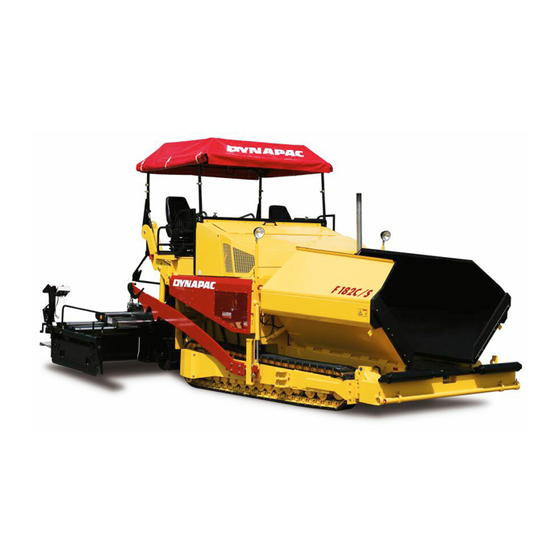
B Vehicle description Application The Dynapac F 182 CS paver finisher is a caterpillar paver finisher which is used for laying bituminous mixed material, roll-down or lean-mixed concrete, track-laying bal- last and unbound mineral aggregates for foundations for paving. F182CS.tif… -
Page 22
Description of assemblies and functions DF135P_side.bmp Denomination Auger Screed Operator’s platform Storage space for toolboxes on the left/right sides Paving thickness indicator Operating panel (can be moved to either side) Protective roof Working lights Material compartment (hopper) Truck push rollers Tube for sensor rod (direction indicator) and holder for levelling shoe Caterpillar drive Travel drive of the caterpillar drive… -
Page 23
Vehicle Construction The paver finisher has a welded steel frame on which the individual components are mounted. The caterpillar drives compensate uneven areas on the ground; the suspension of the attached screed additionally helps to attain a high paving precision. The continuously adjustable hydrostatic travel drive allows the speed of the paver fin- isher to be matched to all work conditions. -
Page 24
Travel drive: The continuously adjustable travel drive pumps are connected to the travel drive engines by means of high pressure hydraulic hoses. These oil motors drive the caterpillar chains via planetary gears that are mounted di- rectly inside the drive wheels of the caterpillar chains. Steering system/operator’s platform: The independent hydrostatic travel drives al- low the finisher to be turned on the spot. -
Page 25
Automatic levelling/slope control system: The slope control system (option) al- lows the regulation of the traction point either on the LH or RH sides, by maintaining a difference defined against the opposite side. To determine the actual value, the two traction crossbeams are linked with a slope control rod. -
Page 26
Danger zones In these areas of the machine there is a danger of pulling in or crushing due to the rotating, transporting or moving parts! -
Page 27
Safety devices Safe operation is only possible when all operating and control elements are function- ing correctly and when all safety devices are in position. Check the function of these devices at regular intervals. (see chapter D, section 2.1). Emergency stop button — on the operating panel — on the two remote control units (op- F0005_A1.EPS… -
Page 28
Main switch (17) Hauptschalter_DF145C_CS.wmf Hopper transport safeguards (18) Hopperlock2.tif/Hopperlock_SK.eps Screed transport safeguards (19) Bohlensich_DF145.wmf Latch for protective roof (20) F121Cb.Tif… -
Page 29
F182CS_side.bmp/Feuerlöscher.bmp No. Denomination 25 Fire fighting device 26 Engine hood 27 Lateral flaps 28 Walkway 29 Screed coverings 30 Screed warning light 31 Auger covers Accessories: — Wedges — Warning triangle — First-aid kit… -
Page 30
Technical data, standard configuration Dimensions (all dimensions in mm) 2300 1000 3360 7020* 1900 2550 3440 *SB 1250 F182CS_side.bmp/ B 10… -
Page 31
For the technical data of the screed, see the operating instructions of the screed. Allowed angle of rise and slope max 15° max 15° max 15° F182CS_side.bmp/F182CS_front.bmp Before operating your machine in an inclined position (gradient, slope, lateral inclina- tion) which is above the specified limit value, please, consult with the customer serv- ice for your machine! Allowed angle of driving up max 14°… -
Page 32
Weights for the F 182 CS (all weights in t) Paver finisher without screed approx. 16.4 Paver finisher with screed: — VB 600 TV approx. 20.3 with extensions for max. working approx. width, additional max.: With filled hopper approx. 18.1 additionally max. -
Page 33
Performance data for the F 182 CS VB 510 TV 2.55 2.00 5.10 8.80 VB 510 TV+ 2.55 2.00 5.10 VB 600 TV 3.00 2.45 6.00 10.00 VB 600 TV+ 3.00 2.45 6.00 9.00 SB 1250TV 3.00 13.50 (gas) *High-compression screeds available on request The maximum working width depends on the paving conditions! Travelling speed 0 — 5,0… -
Page 34
Travel drive/traction unit Drive Hydrostatic drive, continuously controllable Two separately driven caterpillar drives with rub- Drive unit ber grouser chains Turning capacity Turning on the spot Speed See above Engine for the F 182 CS Make/type Cummins QSB6.7-C220 Model 6-cylinder (water cooled) Diesel engine Performance 172 KW / 234 HP (at 2100 rpm) Volume of fuel tank… -
Page 35
Material compartment (hopper) Volume about 7.8 m = about 18.1 t Minimum inlet height, center 500 mm Minimum inlet height, outside 600 mm 5.10 Material transfer Conveyors Left and right side separately controllable Drive Hydrostatic, continuously controllable Conveying volume controller Fully automatic via configurable switching points 5.11 Material distribution… -
Page 36
5.12 Screed lifting device At standstill: — Screed stop — Screed stop with pretensioning (max. pressure 50 bar) Special functions During paving: — Screed charging — Screed relieving (max. pressure 50 bar) Mechanical grade control system, Levelling system optional systems with and without slope control system 5.13 Electrical system… -
Page 37
Location of instruction labels and identification plates B 17… -
Page 38
Denomination Label «Filler neck for diesel fuel» * Label «Filler neck for engine oil» * Label «Operating instructions» Warning label «Danger of squeezing!» ** Label «Securing or fixing points for crane transportation» ** Paver finisher identification label Plate «CE + noise level»(O) Warning plate «Fan danger!»… -
Page 39
Identification label for the paver finisher (6) Fertiger3.tif Denomination Type of paver finisher Year of manufacture Serial number of the paver finisher series Max. permissible operating weight, incl. all extension parts, in kg Max. permissible load on the front axle, in kg Max. -
Page 40
EN standards Continuous sound level The operator always must use ear protection. The imission value at the ear of the driv- er varies depending on the materials used for paving and may even rise above 85 dB (A). If no ear protection devices are used, hearing can be impaired. The noise emission level of the paver finisher was measured under free-field condi- tions according to EN 500-6 draft, dated March, 1997, and ISO 4872. -
Page 41
Vibration acting on the entire body When the machine is used properly, the weighted effective acceleration values at the driver’s seat of a = 0.5 m/s according to EN 1032-1995 draft are not exceeded. Vibrations acting on hands and arms When the machine is used properly, the weighted effective acceleration values at the driver’s seat of a = 2.5 m/s… -
Page 42
B 22… -
Page 43
C 1.4 Transportation Safety regulations for transportation Accidents can happen when the paver finisher and the screed are not properly pre- pared for transportation or when transportation is carried out improperly! Reduce both the paver finisher and the screed to their basic widths. Remove all pro- truding parts (such as the automatic levelling system, auger limit switches, aprons, etc.). -
Page 44
Transportation on low-bed trailers Reduce the paver finisher and the screed to their basic widths; also remove any at- tached side plates. The maximum approach angle is indicated in the section entitled «Technical Data»! Preparations — Prepare the paver finisher for transportation (see chapter D). — Remove all protruding or loose parts from the paver finisher and the screed (see also Screed operating instructions). -
Page 45
Operation Switch Buttons Disabling the interlocking of oper- ation Close the hopper halves. Engage both hopper transport safeguards. Lift the screed. Engage screed transport safeguards. Turn the preselecting regulator to zero. Move the drive lever forward. The levelling cylinder are in fully extended position. -
Page 46
Drive onto the low-bed trailer Make sure that there are no persons in the danger area during loading. F0185_A1.TIF — Use the work gear and low engine speed to drive onto the low-bed trailer. — Lower the screed onto wooden blocks on the low-bed trailer. — Switch off the paver finisher. -
Page 47
Secure the paver finisher in its position to the low-bed trailer: — Use only proper and permitted load fastening devices. — Use the four securing points provided (1, 2). Depending on the equipment of the machine there can be further support points (3) on the auger frame (3)! — Wait until the exhaust extension pipe has cooled down;… -
Page 48
Transportation Reduce the paver finisher and the screed to their basic widths; also remove any at- tached side plates. Preparations — Prepare the paver finisher for transportation (see chapter D). — Remove all protruding or loose parts from the paver finisher and the screed (see also Screed operating instructions). -
Page 49
Operation Switch Buttons Disabling the interlocking of oper- ation Close the hopper halves. Engage both hopper transport safeguards. Lift the screed. Engage screed transport safeguards. Turn the preselecting regulator to zero. Move the drive lever forward. The levelling cylinder are in fully extended position. -
Page 50
Driving mode Warning Marking Marking Set the Fast/Slow switch to «Hare». Turn the preselector to maximum. Use the drive lever to regulate the speed. Press the emergency stop button when a dangerous situation arises! C 1.4 8… -
Page 51
Loading by crane Use only lifting gear that can bear the load. (See Chapter B for weights and dimensions). F0185_A1.TIF Four lifting eyes (1, 2) are provided for loading the vehicle with a crane. — Park the paver finisher and render it safe. — Engage the transport safeguards. -
Page 52
Pendulum drive For the following purposes, a hydraulic cylinder can be used to raise or lower the entire front area of the vehicle chassis: — Adapting to the filling height of the ma- terial transporter or to its tyre size — For driving vehicle onto its low-loader Danger of crushing! Before actuating the shut-off valves on the hopper. -
Page 53
Towing Heed all regulations and apply all safety measures applicable for towing heavy con- struction machines. The towing vehicle must be capable of securing the paver, even on slopes. Use only approved tow bars! If necessary, remove any attachments and extension parts from the paver finisher and the screed until the basic width has been attained. -
Page 54
— Release lock nut (2), screw threaded dowel (3) into pump as far as possible and secure with lock nut. — Actuate lever (4) of hand pump until sufficient pressure has been built up and traction system brakes have been released. -
Page 55
Following towing, unscrew the threaded dowel (3) a few turns again and lock with the lock nut (2). To make the machine ready for opera- tion after repair work, the high-pressure cartridges (1) must be screwed back firmly into place. The traction system brakes are no reac- tivated and the machine is secured against rolling. -
Page 56
Safely parking the vehicle When the equipment is parked at a loca- tion accessible to the public, it must be secured in such a way that unauthorized persons or playing children cannot dam- age the vehicle. — Pull off the ignition key and the main switch (1) and take it with you –… -
Page 57
D 1.7 Operation Safety regulations Starting the engine, the tractin drive, the conveyor, the auger, the screed or the lift- ing devices can cause injuries or even the death of persons. Make sure before starting any of these devices that no-one is working at, in or be- neath the paver finisher or within its danger area! — Do not start the engine or do not actuate any controls when this is expressly forbid- den! -
Page 58
Operating elements Operating panel Bedienpult_SPS_Kette_635_3.bmp,Element1_SPS_Kette_635.bmp,Element2_SPS_Kette_635.bmp,Element3_Kette_C6.7_635_2.bmp D 1.7 2… -
Page 59
General notes on the observation of CE regulations All functions of self-engaging buttons which might provoke a risk during start-up of the diesel engine (conveying function of auger and conveyor) are set to STOP in case of an emergency stop or a control restart. Changes of settings which are performed when the diesel engine is at a standstill („AUTO”… -
Page 60
Element2_SPS_Kette_635.bmp D 1.7 4… -
Page 61
Item Designation Brief description Positions: Ignition and light off Ignition on Parking/rear lights, instrument panel illumination, Ignition lock and il- working lights (if applicable) lumination switch Driving light High beam Not used In the case of an emergency (danger to persons, possible col- lision etc.), press in the button! — Pressing the emergency stop button switches off the en- gine, the drives and the steering system. -
Page 62
Element2_SPS_Kette_635.bmp D 1.7 6… -
Page 63
Item Designation Brief description For switching on the paver finisher functions and for continu- ously regulating the traction speed – forward or reverse. Zero position: starting is possible; engine at idling speed; no traction drive Drive lever Depending on the position of the drive lever, the following (forward — reverse) functions can be activated: Position 1: Conveyor and auger on. -
Page 64
Element1_SPS_Kette_635.wmf D 1.7 8… -
Page 65
Item Designation Brief description Push-button: Left: open left hopper half Right: open right hopper half Open hopper If both hoppers are hydraulically actuated at the same time (1 valve), either the left button or the right button can be used for operation. -
Page 66
Element1_SPS_Kette_635.wmf D 1.7 10… -
Page 67
Item Designation Brief description Self-engaging buttons with LED indication Hare: transport speed Traction drive Tortoise: operating speed for paving fast/slow When restarting, the buttons are set to working speed (tortoise). Self-engaging buttons with LED indication When restarting, the button is set to „Straight-ahead travel”. -
Page 68
Element1_SPS_Kette_635.wmf D 1.7 12… -
Page 69
Item Designation Brief description Not used Vibration Operation and application: see button (20). Self-engaging buttons with LED indication Toggling between two switching conditions. Stop: Operational readiness Auger left/right Auto Reset to STOP in case of an emergency stop or a restart. Button 16 locks the conveying function. -
Page 70
Element1_SPS_Kette_635.wmf D 1.7 14… -
Page 71
Item Designation Brief description Self-engaging button with LED indication Switched off by pressing the button again or by pressing but- ton 25 or 31. 1. „MANUAL” auger operation Requirements: button 24 must be set to „AUTO” „MANUAL” auger — Using the buttons in the pad (left) for the directions of move- operation and lift- ment (29), the conveying speed of the automatic function ing/lowering the… -
Page 72
Element1_SPS_Kette_635.wmf D 1.7 16… -
Page 73
Item Designation Brief description Push-button function Lift screed If the drive lever is in its central position, the speed of the engine rises automatically when moving. Self-engaging button with LED indication Lower screed/screed in floating position The button 16 must be set to „OFF” Screed floating position: Pressing the button turns the LED ON and prepares the screed for „floating position”, which is activated by the actuated drive lever (9). -
Page 74
Element3_SPS_Kette_635_2.wmf/Leuchtmodul_SPS_Kette_635.bmp D 1.7 18… -
Page 75
Item Designation Brief description To query, set and save various operating status and functions Control setting and as well as for displaying messages related to machine and en- display terminal gine. Normal display up to 120 °C = 248 °F. In case of higher temperature stop the machine, (set Hydraulic oil ther- drive lever (9) to neutral position), and let the engine… -
Page 76
Element3_SPS_Kette_635_2.wmf/Leuchtmodul_SPS_Kette_635.bmp D 1.7 20… -
Page 77
Item Designation Brief description It is on, if a major fault occurred in the drive engine. For safety Error message reasons the drive engine stops automatically. with engine stop- After the ignition is turned on, the light comes on for a ping (red) few seconds for checking. -
Page 78
Element3_SPS_Kette_C6.7_2.bmp/Leuchtmodul_SPS_C6.7.bmp D 1.7 22… -
Page 79
Item Designation Brief description It must go dark soon after start. Take heating into account. The hydraulic oil may be too cold and rigid. Signal lamp of the oil If the light does not go dark, do not switch on the pressure in the hy- travel drive (see chapter „Failures“). -
Page 80
Remote control Warning! Do not isolate while operating by remote control provided with emergency stopping button (0). This will lead to stopping the machine! D 1.7 24… -
Page 81
Item Designation Brief description Its function and use are similar to those of the emergency Emergency stop button (7) on the control panel. button (o) It is important in such dangerous situations, which cannot be overseen by the driver. Horn Its function is similar to the button (30) on the control panel. -
Page 82
Warning! Do not isolate while operating by remote control provided with emergency stopping button (0). This will lead to stopping the machine! D 1.7 26… -
Page 83
Item Designation Brief description Auger Its function is similar to the button (24) on the control panel. Conveying direction For the adjustment of the transport direction of the auger of the auger. — switch (61) must be set to „auto“. Transport capacity Plus / minus buttons for the modification of transport capaci- of the auger and… -
Page 84
Bottom part Remote_SPS_neu2.bmp Item Designation Brief description Connection to the levelling Connect the cable for the grade control unit here. automatic system Connection to the end posi- Connect the cable for the material limit switch here. tion switch of the auger Cable for the remote con- Connect to the socket on the screed. -
Page 85
D 2.1 Operation Operation of the input and display terminal TDM.cdr Allocation of the keyboard of the display. — (A) Encoder (Rotation and pressure): — For paging in the menu — For selecting various points within one menu — For the modification of parameters — For confirming the modified parameters — Buttons (B), (C), (D) F1 — F3: — To select the functions displayed on the screen… -
Page 86
Working in the menu TDM.cdr Example: Emergency program (401) — Rotate (A) Encoder until the selection surface (1) appears. — Rotate Encoder (A) until the selection surface gets on the menu point required. — Press (A) Encoder or (B) F2 button to modify the selected menu point. — Adjust the required value by rotating Encoder (A). -
Page 87
Menu structure of the setting and display options The following figure shows the menu structure and operation and it serves the simpli- fication of the procedures in case of various settings and displays. D 2.1 3… -
Page 88
Main menu 00 Display and function menu — Speed — processing mode — Speed — Travel (2) — Engine speed (3) — Road length meter (4) — Fuel consumption (5) — Adjustment possibility „Stopping the screed with Terminal_SPS_Kette_635.wmf/Bild_000.bmp pretensioning“ (6) — 0=The function is inactive — 1=The function is active When the drive lever is in neutral position, the screed retains its position with the… -
Page 89
Menu 01 — Engine speed Adjustment menu of engine speed (1) — Open the submenu: F3). — Back to the main menu: (F1) Terminal_SPS_Kette_635.wmf/Bild_000.bmp Submenu 101 — Setting the engine speed — Saving, back to the main menu: (F3) — Resetting changes, back to the main menu: (F1) Setting is performed in steps of 50, the speed of the en-… -
Page 90
Menu 02 — Measuring value of drive engine Menu to query the various measuring values of the drive engine. — Open the submenu: (F3) — Back to the main menu: (F1) Terminal_SPS_Kette_635.wmf/Bild_000.bmp Submenu 103 — Display of measuring value Drive en- gine Display following… -
Page 91
Menu 03 — Trip meter and fuel gauge Menu to query the various op- erating data — Open the submenu: (F3) — Back to the main menu: (F1) Terminal_SPS_Kette_635.wmf/Bild_003.bmp Submenu 301 — Road sec- tion, fuel consumption dis- play/reset Display of the following serv- ice data: — Fuel consumed (calculated value) (1) -
Page 92
Menu 04 — Emergency func- tion / stopping the screed and turning on the tamper In case of the loss of the specified target value or of the measuring of the actual value (e.g. faulty sensor, transducer), the capacity of the various functions can be set for the automatic opera- tion. -
Page 93
Menu 05 — Layer thickness Menu for setting the type of layer to be processed — Open the submenu: (F3) — Back to the main menu: (F1) Terminal_SPS_Kette_635.wmf/Bild_005.bmp Submenu 501 — Preselec- tion of layer thickness The following types of layers can be selected: — Top layer: 3 parameters — Binder course 2 parame-… -
Page 94
Submenu 502 — Setting the speed of auger The speed can be set in 8 stages. The actual speed se- lected for the applicable feed- er auger is shown on displays (1) and (2). Basic settings applicable to the specific layer types: — Top layer: 4 — Binder course 6 Terminal_SPS_Kette_635.wmf/Bild_502.bmp… -
Page 95
Menu 06 — Screed charging Menu to set the starting load — Open the submenu: (F3) — Back to the main menu: (F1) Terminal_SPS_Kette_635.wmf/Bild_006.bmp Submenu 102 — Starting load setting Setting the duration of start- ing load — Saving, back to submenu 06: (F3) — Resetting changes, back to menu 06: (F1) -
Page 96
Menu 07 — Screed type Menu for adjusting the screed type — Open the submenu: (F3) — Back to the main menu: (F1) Terminal_SPS_Kette_635.wmf/Bild_007.bmp Submenu 701 — Setting the screed type The following screed types can be set: — VB/EB-screed type: 0 pa- rameter — SB-screed: 1 parameter — Saving, back to submenu… -
Page 97
Menu 08 — Service hour me- Menu to query the service hours — Back to the main menu: (F1) or (F3) Terminal_SPS_Kette_635.wmf/Bild_008.bmp D 2.1 13… -
Page 98
Menu 09 — Service Password protected menu to perform the various service settings — Password prompt opening: (F3) — Back to the main menu: (F1) Terminal_SPS_Kette_635.wmf/Bild_009.bmp Submenu 201 — Password prompt Enter password: — The password can be con- firmed by pressing the En- coder — Back to menu 09: (F1) Terminal_SPS_Kette_635.wmf/Bild_201.bmp… -
Page 99
Menu 10 — Error memory Menu for the repeated query of error messages — Display (0): There is no er- ror message — Display (1): Fault message can be displayed — Error message query: (F3) — Back to the main menu: (F1) Terminal_SPS_Kette_635.wmf/Bild_010.bmp Error message display:… -
Page 100
Menu 11 — Error memory Computer of machine oper- ation Menu for the repeated query of error messages sent by the computer of machine op- eration — Display (0): There is no er- ror message — Display (1): Fault message can be displayed Terminal_SPS_Kette_635.wmf/Bild_011.bmp — Retrieval of error message: (F3) -
Page 101
Menu 12 — Program version Menu to query the version number of the installed pro- gram In case you use the help of Technical Support for your machine, always specify the version number of the pro- gram. — Back to the main menu: (F1) or (F3) Terminal_SPS_Kette_635.wmf/Bild_012.bmp D 2.1 17… -
Page 102
Menu 13 — Terminal settings Menu for the various settings of the terminal — Open the submenu: (F3) — Back to the main menu: (F1) Terminal_SPS_Kette_635.wmf/Bild_013.bmp Submenu 104 — Terminal settings Setting of Contrast (1) bril- liance of display (2) and the sensitivity of Encoder (3) — Saving, back to submenu 13: (F3) -
Page 103
Further messages on the display Display No. / report Display message 646 Emergency stop button de- pressed — Back to the previous menu: (F3) message 647 Adjustment mode Displays: — Engine speed (1) — Trip covered (2) — Fuel consumed (calculated value) (3) — Back to the previous menu: (F3) -
Page 104
Terminal error messages Each error message is assigned a number. If you use the help of the Technical Sup- port for your machine, please, provide this number and all information included in the error message. Fault No. / report Display 600. -
Page 105
Fault No. / report Display 610. error message — „drive lever forward“ locked Variable: — Drive / steering direction (1) 615. error message — Sensor of running gear faulty Variable: — LH-side sensor (1) — RH-side sensor (2) 617. error message — Broken line — drive lever pump control 619. -
Page 106
Fault No. / report Display 621. error message — Setup fault of travel speed potentiometer in the service software. 622. error message — Drive lever potentiometer setup-fault in the service software. 623. error message — Short circuit / line fault — drive lever microswitch forward / reverse (parallel switch) -
Page 107
Fault No. / report Display 626. error message — Warning signal of traction engine — SPN = part concerned — FMI = type of fault — OC = frequency of repetition see chapter „Fault codes of traction en- gine“. 628. error message — Communication interrupted Master drive engine 629. -
Page 108
Fault No. / report Display 635. error message — Keyboard fault / Keyboard fuse faulty 636. error message — Remote control fault / Keyboard fuse faulty Variable: — LH-side remote control (1) — RH-side remote control (2) — Remote control fuse (3) 638. -
Page 109
Fault No. / report Display 643. error message — Tamper target value potentiometer faulty 644. error message — Vibrator target value potentiometer faulty 645. error message — Communication interrupted Master display D 2.1 25… -
Page 110
Instructions related to error messages 638. error message Communication interrupted Master drive automatic system. First check if the fuse F5.1 is good. If the cause of the interrupted data link is not the fuse, the Diesel engine can be started. — Switch on button (1) (LED comes on) — Press start button (2). -
Page 111
Fault codes of the traction engine. If a fault occurs in the traction engine, this is indicated by the specific signal lamp (1) and simultaneously an explana- tion appears on the display. Leuchtmodul_SPS_C6.7.bmp The error message displayed simultane- ously includes several error codes, the decoding of which clearly defines the fault. -
Page 112
Example: Explanation: The flashing control lamp marks the serious failure of the traction engine and the en- gine will stop automatically or it has to be stopped. Display: SPN: FMI: Cause: Cable failure in the Rail pressure detector. Effect: The engine switches off. Frequency: The fault occures for the first time. -
Page 113
Error messages D 2.1 29… -
Page 114
D 2.1 30… -
Page 115
D 2.1 31… -
Page 116
D 2.1 32… -
Page 117
D 2.1 33… -
Page 118
D 2.1 34… -
Page 119
D 2.1 35… -
Page 120
Special functions Emergency operation program for the case of keyboard failure To ensure the pavers operating ability during a display failure, an emergency program will be started automatically. Following setting and functions will be max min adjusted and switched on: — Number of revolutions of the Diesel engine: 1800 min — Traction drive (1) slow (Tortoise) -
Page 121
Accessory the following function can be switched by using the remote controls: — Press button (1) to close the hopper. — Press button (2) to open the hopper. — Lifting the screed: — Switch off the LED bar (3) of auger and conveyor completely by using the accompanying Minus-buttons (4). -
Page 123
D3.4 Operation Operating elements on the paver finisher Batteries (71) The batteries of the 24 V system are lo- cated under the left maintenance flap. For the specifications, refer to chapter B, «Technical Data». For servicing, see chapter F. Heed the instructions when starting the paver finisher externally. -
Page 124
Transport safeguards for the hopper (73) Before parking or transporting the paver finisher, the hopper halves must be swung upwards and the transport safe- guards for the hopper must be inserted. Item: — (a) — outside on the two hopper halves — (b) — in the hopper (o) Do not enter the hopper while the engine is running! Danger of being caught by… -
Page 125
Mechanical screed transport safe- guard (to the left and the right be- neath the driver’s seat) (74) It is used to protect the lifted screed from inadvertent sinking. The screed trans- port safeguard must be inserted before transportation and when work is fin- ished. -
Page 126
Separator fluid spraying system (80) Used to spray the parts coming into con- tact with asphalt with a separator emul- sion. A Spray bottle with pressure pump B Spraying system with electric pump (81) Only switch on the spraying system when the diesel engine is running;… -
Page 127
Further switch options for optional equipment features may be located on the central panel: On / off switch for additional head- light in the roof (85): Actuate switch (a) to switch on. On / off switch for filler pump fuel tank (85a) If the pump is actuated with the switch (a), the indicator lamp (b) lights up. -
Page 128
On/Off switch of working lights (85d): Actuate switch (a) to switch on. In the switch position «ON» the indicator lamp (b) is on. On/Off switch of rotary beacon (85e): Actuate switch (a) to switch on. In the switch position «ON» the indicator lamp (b) is on. If optionally available 230 V systems are installed, an additional switch cabinet is mounted on the paver finisher:… -
Page 129
Locking of the collapsible roof (LH and RH on the roofs console) (86) To lower the roof (for example during transport on a low bed trailer): — Loose the twistlock (A). — Pull the roof frame forward holding the clevis or the frame. — Arrest the twistlock in the second lock- ing hole. -
Page 130
Hydraulic folding roof (87) (o) The hydraulically folding roof is secured by means of a latch (A) at the rear sus- pension on the left and right sides of the machine. This must be released prior to lowering and raising. Once it has reached its terminal position, the roof must be secured with the latch again. -
Page 131
Electric setting of the transportation volume of the conveyor (o) (88) With this the transport volume of the conveyor can be adjusted when me- chanical limit switch or ultrasonic sensor is used. — The «0» position of the scale corre- sponds to the smallest adjustable vol- ume. -
Page 132
Conveyor limit switches (89): The mechanical conveyor limit switches (89) or the ultrasonic conveyor limit switches (89ao) control the material flow at the respective conveyor half. The conveyors should stop when the materi- al has roughly reached the area below the auger tube. -
Page 133
Ultrasonic auger limit switches (90) (left and right) The limit switches control the material flow at the respective auger half. The ultrasonic sensor is mounted by means of an appropriate leverage to the side plate. Loose clamping lever for ad- justment and modify angle / height of the sensor. -
Page 134
Pressure control valve for screed charging/relieving (93) (o) Used to adjust the pressure for addition- al charging/relieving of the screed. — See «screed charging/relieving de- vice». (Chapters «Operating Panel», «Opera- tion»). — Pressure display: see manometer (93b). Pressure control valve for screed stop with pretensioning (93a) (o) This valve is located beneath the right- hand bottom flap of the operator’s plat-… -
Page 135
Central lubrication unit (o) (100) The central lubrication unit turns on in automatic mode when the drive engine starts. — Pumping time: 12 min — Duration of the break: 2 h It is prohibited to change the factory-set durations of pumping and break without consulting the technical customer serv- ice! Changing the duration of lubrication and… -
Page 136
Particle filter – indicator lamp (102) The indicator lamp of the particle filter is found under the control track of the oper- ating panel. When observing the indicator lamp (a) it is essential (a): Partikellight.tif Indicator col- Operating condition Cause / action No counterpressure. -
Page 137
Front and side window (o) (103) The front window can be folded up for the maintenance works performed at the tank. — Fold the front window by its handle (A) and lock it on the RH and LH sides with the two locks (B) in the upper po- sition. -
Page 138
Adjustment of screed eccentric (o) (104) To pave thicker layers of material, if the piston rods in the levelling cylinder are operating close to their limit position and if the desired paving thickness cannot be reached, it is possible to alter the ap- proach angle of the screen by adjusting the eccentric. -
Page 139
D 4.13 Operation Preparation of operation Required devices and aids To avoid delays on site, check before starting work whether or not the following de- vices and aids are present: — Wheel loader for transporting heavy extendable parts — Diesel fuel — Engine oil and hydraulic oil, lubricants — Separating fluids (emulsion) and manual injector — Two filled propane gas bottles… -
Page 140
Checklist for the machine operator Check! How? Emergency stop button Push in the button. — on the operating panel The diesel engine and all running drives — on both remote control units o must stop immediately. The paver finisher must immediately fol- low every steering wheel movement in a Steering precise manner. -
Page 141
Check! How? For larger working widths, the walkway Auger covers plates must be extended and the auger tunnels must be covered. For larger working widths, the walkway plates must be extended. Hinged walkway plates must be swung Screed covers and walkways down. -
Page 142
Starting the paver finisher Before starting the paver finisher Before starting the diesel engine and beginning operation, the following steps must be performed: — Daily maintenance of the paver finisher (see chapter F) Check the operating hour counter to determine whether or not additional mainte- nance work (such as monthly or yearly maintenance) must be performed. -
Page 143
External starting (starting aid) The engine can be started with the help of an external power source if the batteries are empty and the starter no longer turns. Suitable power sources are: — Other vehicles with a 24 V system — Additional 24 V battery — Start device that is suitable for external starting (24 V/90 A). -
Page 144
After starting To increase the engine speed: — Set the drive lever (9) to position 1 (slightly off the center position). — Increase the engine speed by press- ing button (21) on the operating panel. The engine speed will be increased to the preselected value. -
Page 145
Oil pressure indicator lamp for the travel drive (46) — Must go out after starting. If the lamp does not go out: Do not switch on the travel drive! Other- Leuchtmodul_SPS_C6.7.bmp wise, the entire hydraulic system could be damaged. When the hydraulic oil is cold: — Set the conveyor switch (32) to «man- ual»… -
Page 146
Battery charge indicator (49) Must go out after starting when the en- gine revs up. If the lamp does not go out or lights up during operation: Briefly rev up the en- Leuchtmodul_SPS_C6.7.bmp gine. Switch off the engine and determine the cause for the malfunction if the lamp does not go out. -
Page 147
Operation in case of transportation Lifting and securing the screed — Button (16) has to be switched off — Switch off the buttons (34) and lift the screed full by using button (33). — Extend the levelling cylinders full by using the buttons (25) and (27). -
Page 148
Driving and stopping the paver finish- — Set the Fast/Slow switch (17) to «Hare». — Set the preselector (10) to mark 10. — For driving, carefully tilt the drive lever (9) forward or backward according to the drive direction desired. In case of an emergency, press the emergency stop button ((7)! — To stop the paver finisher, set the… -
Page 149
Preparations for paving Separating fluid Spray the parts coming into contact with asphalt (hopper, screed, auger, push roller) with a separator fluid. Do not use diesel fuel as it dissolves the bitumen (prohibited in Germany!). F0147_A1.TIF Screed heater Switch on the screed heater approx. 15–30 minutes (depending on the ambient tem- perature) before paving begins. -
Page 150
Direction marks To ensure straight paving, a direction mark must be present or established (road edge, chalk lines or similar). — Slide the operating panel to the de- sired side and secure it. — Pull the direction indicator out of the bumper (arrow) and adjust it accord- Stossstange.bmp ingly. -
Page 151
— Switch the conveyors on. The limit switches for the conveyors (89) or (89ao must switch off when the material has reached the area be- neath the auger crossbeam. — Check that the material is transferred properly. Manually switch on or off the conveyor if the material is not conveyed properly until a sufficient amount of material lies in front of the screed. -
Page 152
Starting for paving Element2_SPS_Kette_635.wmf/Element1_SPS_Kette_635.wmfr/Tamprev.cdr/Vibrev.cdr/Remote_SPS_neu1cdr D 4.13 14… -
Page 153
Set the switches, levers and controls listed below to the specified positions when the screed has reached its operating temperature and a sufficient amount of material lies in front of the screed: Switch Position Travel / work gears Tortoise-operating speed Travel drive preselector Mark 6-7 Preparation for screed floating posi-… -
Page 154
Checks during paving The following points must be constantly observed during paving: Paver finisher function — Screed heater — Tamper and vibration — Engine oil and hydraulic oil temperature — The screed parts must be retracted and extended in time when obstacles are in the — Uniform material transport and distribution or supply to the screed;… -
Page 155
Screed charging/relieving This function charges or relieves the screed regardless of its own dead weight. Switch (34) has the following positions: A: Relieving (screed ‘lighter’) B: Charging (screed ‘heavier’) Switch positions «Screed charging/re- lieving» are only effective when the pav- er finisher moves. -
Page 156
Screed stop with prestressing With the «Screed stop» function it is possible to block the hydraulic system of the screed, which stops the sinking of the screed in case of temporary stopping. Switch (34) must be turned off. — Automatic screed stop when the drive lever is in the center position — To lift the screed press button (33A). -
Page 157
Adjusting the pressure (o) Pressure adjustments can only be made while the diesel engine is running. Therefore: — Start the diesel engine and set the traction controller (10) to zero (precau- tion against inadvertent advancing). — Set switch (33) to the floating position. — Set the drive lever (9) to the center po- sition. -
Page 158
Interrupting/terminating operation During breaks: (e.g. the material supply truck is late) — Determine the approximate duration. — When cooling down of the material be- low the minimum paving temperature must be expected, run the paver fin- isher empty and create an edge like the end of a layer. -
Page 159
— Insert the mechanic screed transport safeguard (74) on both screed lifting cylinders. — While operating the tampers at a low speed, let any material residues drop out. Bohlensich_DF145.wmf — Set the drive lever (9) to the center po- sition and the speed adjuster (10) to minimum. -
Page 160
— Read and check the oper- ating hour meter to deter- mine whether maintenance work must be performed (see chapter F). — Cover and lock the operat- ing panel. — Remove material residues from the screed and the paver finisher and spray all parts with separator fluid. -
Page 161
Malfunctions Problems during paving Problem Cause — change in the material temperature, demixing — wrong material composition — incorrect operation of the roller — incorrectly prepared foundation — long standstill times between loads — grade control reference line is not suitable — grade control jumps to the reference line — grade control toggles between up and down Wavy surface… -
Page 162
Problem Cause — temperature of the material — screed extendable parts are incorrectly installed Cracks in the layer — limit switch is not correctly set (outer strip) — cold screed — bottom plates are worn or warped — paver finisher speed is too high — temperature of the material — change in the material temperature — moisture on the foundation… -
Page 163
Malfunctions on the paver finisher or screed Malfunction Cause Remedy See operating instructions for At the diesel engine Diverse the engine See «External starting» (start as- Batteries empty Diesel engine does sistance) not start Diverse see «Towing» Tamper is obstructed by Properly heat the screed cold bitumen Hydraulic oil level in the… -
Page 164
Malfunction Cause Remedy Control valve is defective Replace Hoppers lowers in- Leaking seals of the hy- advertently Replace draulic cylinder Oil pressure too low Increase the oil pressure Leaking seal Replace Screed cannot be lift- Screed relieving or charg- Switch must be in the center po- ing is switched on sition Check fuse and cables;… -
Page 165
Malfunction Cause Remedy Traction drive fuse defec- Replace (Fuse holder on the op- tive erating panel) Check potentiometer, cables, Power supply is interrupted connectors; replace if necessary Travel drive monitoring Replace (type-specific) defective Traction does not Electro-hydraulic servo unit Replace the servo unit work of the pump defective Check and adjust if necessary… -
Page 166
Emergency device/steering, travel drive In case of a malfunction in the electronic drive system it is possible to override the system by an emergency device. This emergency device is included in the tool set of every caterpillar machine. To install the emergency device all plugs of the travel drive pump servo valves have to be replaced by the plugs of the emergency device. -
Page 167
Following functions are located in the control unit: No. Denomination Mounting screws for holder plate Switch for preselection of the zero position and forward reverse movement Adjustment knob for speed control (Replace speed preselector) Steering knob Switch to turn the paver on the spot Function If the emergency device is connected all functions like engine speed, conveyor, au- ger, tamper and vibration have to be controlled by the drive lever. -
Page 168
GREY Wiring harness for the BLACK drive pump on the left drive unit Marked YELLOW! 24 V / earth/ground control unit D 4.13 30… -
Page 169
E 02 Set-up and modification Special notes on safety Danger to personnel by inadvertent starting of the engine, travel drive, conveyor, au- ger, screed or lifting units. Unless otherwise specified, work may only be performed when the engine is at a standstill! — To protect the paver finisher against inadvertent starting: Set the drive lever to the centre position and set the preselector to zero;… -
Page 170
Distribution auger Height adjustment At layer height of up to 15 cm, the height of the auger (1) – measured from its low- er edge – should, depending on material mixture be approx. 5 cm (2 inches) above the material layer height, depend- ing on material mix. -
Page 171
With hydraulic adjustment (option) — Determine the currently set height of the auger crossbeam (left and right) by means of the scale (1). F0117_A1.EPS Actuate both switches (2) simultaneous- ly to avoid auger crossbeam warping. — Check whether the heights on the left and on the right are identical. -
Page 172
Auger extension E 02 4… -
Page 173
Mounting extension parts Sch_ver1.tif Sch_ver2.tif E 02 5… -
Page 174
— Secure material shaft (5) with screws (6), washers (7) and nuts (8) to the basic unit. — The material shaft is adjustable to enable it to be aligned with the existing shaft. — To do this, unfasten nuts (9) and guide aperture (10) for the screw (6). — Fit auger shaft extension (11) to auger shaft of basic unit. -
Page 175
Offset screed position towards back Depending on planing conditions and re- quirements, the crossbeam can be moved towards the back. This positional adjustment enlarges the material shaft between auger and screed. — Loosen the four fastening screws (1). — Remove the screws and move the ma- chine forwards. -
Page 176
Screed The Screed operating instructions cover all work required for mounting, setting up and extending the screed. Electrical connections Establish the following connections when the mechanical components have been mounted and set up: Connect remote controls to socket (15) (on the screed). Socket.bmp Connect grade control to socket (16) (on the remote control… -
Page 177
F 1.0 Maintenance Notes regarding safety Maintenance work: Maintenance work may only be carried out when the engine is at a standstill. Secure the paver finisher and the attachments against inadvertent starting before be- ginning any maintenance work: — Set the drive lever to the center position and the speed preselector to zero. — Remove the traction drive fuse from the operating panel. -
Page 179
F 2.8 Maintenance review Maintenance review 6.2 8.5 F 2.8 1… -
Page 180
Maintenance required after the following service hours Sub-units Chapter Conveyor F3.4 Auger F4.1 q q q q Drive engine F5.3 q q q Hydraulics F6.2 q q q q Drive units F7.6 q q q Electronics F8.5 Lubrication points Checking/stopping Maintenance required In this overview, you will find the maintenance intervals for optional machine equip- ment! -
Page 181
F 3.4 Maintenance — Conveyor Maintenance — Conveyor F 3.4 1… -
Page 182
Maintenance intervals Interval Points of maintenance Remark — Conveyor chain — Check tightness — Conveyor chain — Adjust tightness — Conveyor drive — drive chains — Check chain tightness — Conveyor drive — drive chains — Adjust chain tightness — Conveyor planetary gear — Check oil level — Conveyor planetary gear — Top up oil… -
Page 183
Points of maintenance Chain tightness of the conveyor (1) Checking the chain tightness: For daily inspection look straight through under the bumper. When conveyor chain is correctly tensioned, the lower edge of the chain is approx. 4 cm below the lower edge of the chassis. The conveyor chains should not be too tight or too slack. -
Page 184
Conveyor drive — drive chains (2) To check the chain tension: — If the tension has been set properly, the chain must be able to move freely approx. 10 — 15 mm. To re-tension the chains — Unfasten retaining bolts (A) and lock- nut (B) slightly. -
Page 185
Conveyor drive planetary gear (left and right) (3) — For oil level check unscrew the in- spection bolt (A). When oil level is correct, the oil comes up to the lower edge of the inspection bore or a small amount of oil escapes through the aperture. -
Page 187
F 4.2 Maintenance — Auger Maintenance — Auger sub-unit I F 4.2 1… -
Page 188
Maintenance intervals Interval Points of maintenance Remark — Auger — outer bearing Lubrication — Auger central bearing Lubrication — Auger drive neck bearing Lubrication — Auger bevel gear oil level check — Auger bevel gear topping up the oil — Auger bevel gear oil change Maintenance Maintenance during run-in period… -
Page 189
Points of maintenance Auger — outer bearing (1) The grease nipples (A) are located on each side on the top of outer bearing. These nipples must be lubricated each time when work is finished. The outer bearings of the auger shall be lubricated when hot, so that the eventual bitumen residues are expelled. -
Page 190
Auger — drive gear neck bearing (3) Remove the hexagonal screw plug (A) in the neck of the drive. Replace the screw under it with a grease nipple 10×1. Using a grease gun press in about 10 strokes of grease. Thereafter, unscrew the grease nipple and drive in both screws. -
Page 191
Auger bevel gear (on the RH and LH sides) (4) — For checking the oil level unscrew the inspection / filling plug (A). In case of proper oil level, the oil is at the lower edge of the inspection port or a lit- tle oil flows from the hole. -
Page 193
F5.3 Maintenance — Engine Maintenance — Engine In addition to these maintenance instructions, the maintenance instructions issued by the engine manufacturer must be adhered to under all circumstances. All other main- tenance work and intervals noted in these instructions are also binding. F5.3 1… -
Page 194
Maintenance intervals Interval Points of maintenance Remark — Fuel tank Check filling level — Fuel tank Refill with fuel — Fuel tank Clean the tank and system — Engine lube-oil system Check oil level — Engine lube-oil system Top up oil — Engine lube-oil system Change oil — Engine lube-oil system… -
Page 195
Interval Points of maintenance Remark — Engine air filter Check air filter — Engine air filter Empty dust collecting bin — Engine air filter Air filter cartridge Clean / replace — Cooling system of the engine Check radiator fins — Cooling system of the engine Clean radiator fins — Cooling system of the engine Check level of the coolant… -
Page 196
Points of maintenance Engine fuel tank (1) — Check the filling level on the gauge on the operating panel. Fill the fuel tank before each start of work so that the fuel system cannot «run dry» and this way the time consuming venting (bleeding) can be avoided. -
Page 197
Engine lube-oil system (2) Checking the oil level In case of correct oil level, the oil is be- tween the two notches of the dipstick (A). Check the oil level with a paver finisher standing on a flat area! If there is too much oil in the engine, the gaskets and seals may get damaged, while too little oil can lead to the over- heating of the oil and the damage of the… -
Page 198
Changing the oil filter: As part of the oil change mount the new filter after the used oil was drained. — Untighten the filter (D) and clean its resting surface. — Apply thin coat of oil to the seal of the new filter and fill the filter with oil before mounting. -
Page 199
Engine fuel system (3) The fuel filter system consists of three fil- ters: — Pre-filter (A) with water separator — Main filter (B) Depending on the machine, the pre-filter is in the engine compartment or under the tank lid! Pre-filter — draining of water Empty the collection bin by the specified intervals or when the engine electronic indicates a fault. -
Page 200
Replacing of main filter: — Untighten the filter (B) and clean its resting surface. — Apply a thin coat of oil to the gasket of the new filter. — Tighten the filter by hand. After mounting the filter check for proper tightness during the trial run. Venting the filter: — Unscrew handwheel of the pump (E). -
Page 201
Engine air filter (4) Emptying the dust collection bin — Empty the dust collection valve (B) on the air cleaner housing (A) by pressing the discharge port in the direction of the arrow. — Discharge the eventually compacted dust by pressing together the upper part of the valve. -
Page 202
Coolant system of the engine (5) Checking / topping up of coolant The coolant level is checked when the engine is cold. Make sure that the anti- freeze and anti-corrosive liquid us suffi- cient (-25 °C). When hot, the system is under pressure. When opening, there is a danger of scalding! — If necessary fill in sufficient amount of… -
Page 203
Engine exhaust system (7) Cleaning of particle filter As considerable amount of soot is accu- mulated in the filter, the cleaning must be performed under an appropriate suc- tion system. Clean the filter element removed with oil-free and grease-free pressure air! — Marking the flow of direction of the ex- haust gas on the filter case. -
Page 205
F 6.2 Maintenance — Hydraulic system Maintenance — Hydraulic system F 6.2 1… -
Page 206
Maintenance intervals Interval Points of maintenance Remark — Hydraulic oil tank — Check filling level — Hydraulic oil tank — Top up with oil — Hydraulic oil tank — Change oil and clean — Hydraulic oil tank — Check maintenance indicator — Hydraulic oil tank — Intake / return hydraulic filter;… -
Page 207
Points of maintenance Hydraulic oil tank (1) — Oil level check on dipstick (A). In case of retracted cylinders the oil level shall be at the upper mark. For filling in the oil: — Remove cap (B). — Fill in oil through the filling port until the required filling level is achieved on the dipstick (A). -
Page 208
Suction/return flow hydraulic filter (2) Replace the filter cartridges if the (A) and (B) maintenance indicators reach the red mark. When changing the hydraulic oil, the fil- ters also need to be changed. — Unscrew the lid of the filter housing on the hydraulic tank and replace the fil- ter cartridge. -
Page 209
High pressure filter (3) Replace the filter cartridge when the maintenance indicator (A) turns red. — Unscrew filter house (B). — Remove the filter cartridge. — Clean the filter housing. — Insert the new filter cartridge. — Replace the seal ring of the filter hous- ing. -
Page 210
Pump distribution gear (4) — Check oil level on the viewing glass (A) (at the side of the distribution box). The oil level must be up to the center of the viewing glass. For filling in the oil: — Unscrew the filler screw (B). — Fill in oil through the filling port until the required filling level is achieved on the viewing glass (A). -
Page 211
Hydraulic hoses (5) — Check the condition of the hydraulic hoses specifically. — Immediately replace the injured hos- The aged hoses may become porous and burst! Risk of accident! The numbers stamped in the joints of the hoses state the date of manufacture (A) and the maximum pressure (B) allowed for that hose. -
Page 212
Auxiliary flow filter (6) Replacing filter element: — Unfasten screw connection on cover (A) then open the non-return valve briefly to lower the oil level in the filter, then close the non-return valve again. — Replace filter element (B) and sealing ring (C): — Turn filter element clockwise with the help of carrier straps and, at the… -
Page 213
F 7.6 Maintenance – Drive units Maintenance – Drive units F 7.6 1… -
Page 214
Maintenance intervals Interval Points of maintenance Remark — Chain tension — Check q — Chain tension — Adjust — Planetary gear — Check oil level q — Planetary gear — Top up oil — Planetary gear — Change oil — Lubrication points Grease the track mounting — Lubrication points Grease the track guide… -
Page 215
Points of maintenance Chain tightness (1) Checking the chain tightness: If the chains/tracks are not tensioned sufficiently, they can slip out of their guide formed by rollers, drive gear and idler wheel, thereby increasing wear levels. If the chains/tracks are tensioned too tightly, this increases wear on the idler wheel and drive unit mounting, and also increases wear on track bolts and bushes. -
Page 216
Planetary gear (2) — For oil level check unscrew and re- move the inspection bolt (A). When oil level is correct, the oil comes up to the lower edge of the inspection bore or a small amount of oil escapes through the aperture. -
Page 217
Lubrication points (3) Drive unit mounting There is a grease nipple (A) behind the crossbeam on both sides of the drive unit chassis. F182CS_LL Drive unit guide There is a grease nipple (A) on both sides of the drive unit guide. F182CS_LF F 7.6 5… -
Page 219
F 8.5 Maintenance — Electronic system Maintenance — Electronic system F 8.5 1… -
Page 220
Maintenance intervals Interval Points of maintenance Remark Filling level of battery electrolyte — check q Top up with distilled water Coat the battery poles with grease Maintenance Maintenance during run-in period F 8.5 2… -
Page 221
Interval Points of maintenance Remark — Generator Also see the Checking of operation of the insula- operation tion monitoring manual of Check function the screed — Generator Visual checking for pollution or dam- — Check the cooling air openings for pollution or clogging, clean as re- quired. -
Page 222
Interval Points of maintenance Remark q Electric fuses Maintenance Maintenance during run-in period F 8.5 4… -
Page 223
Points of maintenance Batteries (1) Maintenance of batteries The batteries are filled with the appropri- ate volume of electrolyte in the factory. The electrolyte level shall be up to the top mark. Top up with ion exchanged water only, when required! The shoes shall be free of oxyde and coated with special battery protection grease. -
Page 224
Generator (2) Checking of operation of the insulation monitoring Check insulation daily with operating machine and switched on connection sockets. — Turn on the electrical equipment with switch (1), control light (2) comes on. — Press testing button (3) and the in- scription «Insulation Fault»… -
Page 225
Checking of ball bearings / Replace- ment of ball bearings Report the displayed fault code to the customer service of the paver finisher and they will discuss with you the steps to be taken. F 8.5 7… -
Page 226
Drive belts (V-belt) Checking belt tension The tightness of each belt shall be in- spected with a tightness checking instru- ment. Specified tension: — in case of first assembly: 550N — after the run-in period / maintenance interval: 400N Riemensp.tif Instructions for checking of tightness in the description of the tightness measuring instrument. -
Page 227
Drive belt (toothed belt) Replacement of belt — Unfasten both lock nuts (A) from the clamping lock. — Rotate and open clamping lock (B) un- til belt (C) can be replaced. Pre-tension newly fitted belt using clamping lock (B). — Checking / adjusting belt tension Riemenspann.jpg F 8.5 9… -
Page 228
Checking / adjusting belt tension: The tension of the V-belt must be checked and set after the belt has been replaced. — The tension of the belt can only be ad- justed using a pre-tensioning test de- vice. Deflection Specified belt tension levels: (read from bottom to top) — Generator 17KVA:… -
Page 229
Electric fuses (3) Type of machine: PLC electronics Fuses_635_konv.eps Main fuses Fuses in terminal box Relays in terminal box Main fuses (A) Lighting, engine Lighting, engine (o) F 8.5 11… -
Page 230
Fuses in terminal box F5.5 Travel drive, automatic steering system Travel drive Temperature control, electric heating Gas heating, power supply to screed Integrated receptacles Integrated receptacles Integrated receptacles Integrated receptacles Engine start Slave A51 Slave A52 Slave A53 Slave A54 Slave A55 Slave A56 (auxiliary functions) 41.1… -
Page 231
Spraying system Emulsion spraying system Diesel tank filler pump Rotary beacon Lighting on glassfibre-reinforced roof Working lights (o ) Power supply, Master A1 Particulate filter (o) Asphalt fume control system (o) Seat heating Windscreen wiper Reserve, engine compartment lighting Power supply, Master A1 Lighted height scale F 8.5 13… -
Page 232
Relays in terminal box (C) Engine start Horn Travel drive Start interlock Reverse buzzer Power supply to terminal 15 Engine feedback control F 8.5 14… -
Page 233
Fuses on operating panel Bedienpult_SPS_Kette_635_2/Fuse1.tif/Fuse.bmp Fuse carrier (A) Emergency stop Monitoring equipment, relay batt. 15+,, Engine sensors Display power supply Keyboard power supply Free Free Screed power supply, moving cab (o) Free Fuse carrier (B) Free Horn, reverse buzzer Winscreen wiper (o), crowning adjustment High-beam headlights, left/right Working light, front right Working light, front left… -
Page 235
F 9.0 Maintenance — Points of lubrication Maintenance- Points of lubrication The information related to the lubrication points of the various sub-units are included in the specific maintenance descriptions and additional reading is recommended as follows. In case of applying a central lubrication unit (o) the number of the lubrication points may differ from the data provided in the description. -
Page 236
Maintenance intervals Interval Points of maintenance Remark — Check the filling level of the lubri- cant tank q — Fill up the lubricant tank — Vent the central lubrication unit — Check the pressure limiting valve — Check the leakage of the lubri- cant at the consumer unit — Bearings Maintenance… -
Page 237
Points of maintenance Central lubrication (1) Danger of injuries! Do not reach into the tank when the pump is running. Operate the central lubrication system with a mounted safety valve only! During operation do not perform mainte- Handverl.jpg/Gefahr.jpg nance operations on the safety valve! The lubricant ejected may cause injuries as the equipment operates under high pres- sure! Make sure that the starting of the diesel engine should be prohibited while work is per-… -
Page 238
Central lubrication unit Check the filling level The lubrication tank shall always be filled so that the system could not „run dry“ and the proper lubrication of the points of lubrication is ensured and there is no need for a time consuming venting operation. -
Page 239
Vent the central lubrication unit The venting of the lubrication system be- comes necessary if the central lubrica- tion unit was operated with an empty lubrication tank. — Untighten the main line (a) of the lu- brication pump at the flow divider (b). — Start the operation of the central lu- brication unit with the refilled lubri- cant tank (c). -
Page 240
Check the leakage of the lubricant at the consumer unit Check the continuity of all the lubrication canals at the consumers. — Disconnect the lubrication pipe (a) and fit a standard grease nipple (b). — Connect the grease gun (c) supplied with the machine to the grease nip- ple (b). -
Page 241
Bearings (2) There are grease nipples on the bearing points of the hydraulic cylinder (one each, at the top and bottom) (a). Zylinder.bmp F 9.0 7… -
Page 243
F 10.0 Checks, decommissioning Tests, check-up, cleaning, stopping F 10.0 1… -
Page 244
Maintenance intervals Interval Points of maintenance Remark — General observation q — Checks by a specialist q — Cleaning q — Conservation of paver finisher Maintenance Maintenance during run-in period F 10.0 2… -
Page 245
General observation The daily practice includes the walk around the machine with checking the following items: — Are there injuries on the parts or control elements? — Are there leaks on the engine, the hydraulics, the gear box, etc.? — Are all the locking points secure (conveyor, auger, screed)? Repair the detected faults immediately in order to avoid risks of accidents and envi- ronmental pollution! Checks by a specialist… -
Page 246
Cleaning — Clean all parts which come into contact with the material to be laid. — Spray the polluted parts with the separating agent spray equipment (o). Before cleaning with high pressure jet, lubricate all the bearings with grease as spec- ified. -
Page 247
Conservation of paver finisher Downtime up to 6 months — Stop the machine in a place protected from intensive sunshine, wind, moisture and frost. — Lubricate all the lubrication points with grease as specified, use the optional central lubrication unit as appropriate. — Change the oil in the Diesel engine — Tightly seal the muffler of the exhaust pipe. -
Page 249
F 11.1 Lubricants and operating sub- stances Lubricants and operating substances Use only the lubricants listed below or comparable qualities of well-known brands. Use only clean containers (inside and outside) for pouring oil or fuel in. Pay attention to the correct filling volumes (see the section “Filling volumes”). Incorrect oil or lubricant levels promote rapid wear and cause the paver finisher to fail. -
Page 250
Hydraulic oils Preferred hydraulic oils: a) Synthetic hydraulic liquids based on ester, HEES Manufacturer ISO viscosity class VG 46 Shell Naturelle HF-E46 Panolin HLP SYNTH 46 Esso HE 46 Total Fina Elf Total Biohydran SE 46 b) Mineral oil pressure fluids Manufacturer ISO viscosity class VG 46 Shell… -
Page 251
Filling volumes Operating substance Volume Fuel tank Diesel fuel litres Hydraulic oil reservoir Hydraulic oils litres Diesel engine See Engine operating Engine oil (with oil filter change) instructions. Pump distribution gear Gear oil 90 litres Planetary gear — Gear oil 220 litres drive unit Planetary gear — conveyor… -
Page 252
Notes on changing over from mineral oil to synthetic oil / synthetic oil to min- eral oil Drive unit planetary gear Never mix synthetic oils with mineral oils! — Always drain used oil completely. Change the oil when the engine is at op- erating temperature. -
Page 253
TRAINING/EDU- CATION We offer our Customers various training programmes on DYNAPAC equipment in our specialised training centre in our factory. We hold train- ing sessions also for special arrange- ments in addition to courses and programs held on fixed dates SERVICE In case of operational failures and questions related to parts, please, contact one of our au-… -
Page 254
Don’t hesitate to contact your local dealer for: service spare parts documentation accessories information about the complete Dynapac paving and planing range…
- Файлы
- Академическая и специальная литература
- Промышленное и гражданское строительство
- Строительные машины и оборудование
- Руководства по эксплуатации, обслуживанию и ремонту
- Руководства по эксплуатации, обслуживанию и ремонту асфальтоукладчиков
-
Файл формата
pdf - размером 8,70 МБ
- Добавлен пользователем spectrol 09.08.2017 22:58
- Описание отредактировано 09.08.2017 23:45

Dynapac (Atlas Copco Group) — 240 с.
Содержание
Введение
Назначение и надлежащее использование
Описание машины
Транспортировка
Работа/ управление
Эксплуатация
Регулировки и модификации
Техническое обслуживание
- Чтобы скачать этот файл зарегистрируйтесь и/или войдите на сайт используя форму сверху.
- Регистрация
- Узнайте сколько стоит уникальная работа конкретно по Вашей теме:
- Сколько стоит заказать работу?
Dynapac operator’s, electrical wiring diagrams, workshop, service and repair manuals, spare parts catalogs, error codes in PDF download
|
Title |
File Size |
Download Links |
|
Dynapac BA41 / BB Series Instructions And Spare Parts Catalogue |
1.3Mb |
Download |
|
Dynapac CA 150 Operation & Maintenance Manual [PDF] |
692.4kb |
Download |
|
Dynapac CA 150 / 152 Workshop Manual [PDF] |
391.5kb |
Download |
|
Dynapac CA 252 / 302 / 402 Operation & Maintenance Manual |
483.5kb |
Download |
|
Dynapac CA2500 / 2800 / 3500 / 4000 Operation & Maintenance |
21Mb |
Download |
|
Dynapac CC 501 / 501C Operation & Maintenance Manual [PDF] |
394.6kb |
Download |
|
Dynapac CC-900 Spare Parts Catalogue [PDF] |
1.3Mb |
Download |
|
Dynapac CC1000 Spare Parts Catalogue [PDF] |
3.4Mb |
Download |
|
Dynapac CC122 TEchnical Specifications [PDF] |
651.3kb |
Download |
|
Dynapac CC224 Electric Wiring Diagrams [PDF] |
77.5kb |
Download |
|
Dynapac CC324HF Spare Parts Catalogue [PDF] |
3Mb |
Download |
|
Dynapac CC424CHF / CC524CHF Operation & Maintenance Manual |
4.3Mb |
Download |
|
Dynapac CC624H Operation & Maintenance Manual [PDF] |
6.2Mb |
Download |
|
Dynapac CC800 / 900 / 1000 Operation & Maintenance Manual |
11.9Mb |
Download |
|
Dynapac F1000W T4f Operation & Maintenance Manual [PDF] |
49.5Mb |
Download |
|
Dynapac F1250CS Operation & Maintenance Manual [PDF] |
12Mb |
Download |
|
Dynapac F80W Workshop Manual [PDF] |
46.9Mb |
Download |
|
Dynapac ICC1200C-1EN3 Operation & Maintenance Manual [PDF] |
4.5Mb |
Download |
|
Dynapac LT600 / 700 Operation & Maintenance Manual [PDF] |
455kb |
Download |
|
Dynapac SCC102 Spare Parts Catalogue [PDF] |
2.7Mb |
Download |
|
Dynapac SD2500C / SD2500CS Paver Finisher Operation & Maintenance |
16.6Mb |
Download |
|
Dynapac SD2550C / SD2550CS Operation & Maintenance Manual |
17.4Mb |
Download |
The company is one of the leading world suppliers of such road-building equipment such as: road mills, asphalt puppiders, road and asphalt rinks Dynapac, vibrors, vibration stations. It is also
worth noting that the Patent for the asphalt stackers of Svedala Demag was purchased by Dynapac. These asphalt stimulars are made under the Dynapac brand of the SD series.
Dynapac road cutters, asphalt pavers and other equipment are produced at factories in Sweden, France, Brazil, India, Germany, China. The company’s headquarters is located in Stockholm, Sweden.

The history of Dynapac. In 1934, on the basis of the acquisition of a patent on the vibrational seal of concrete in Stockholm, Sweden, AB Vibro-Betong was founded.
- In 1941, a plant was opened in Jungby, Sweden
- In 1947, the first vibrating plate was released.
- 1946 — the first plant was opened outside of Sweden, in the United States of America.
- 1948-opening of a research laboratory.
- 1953 — release of the first vibration rink.
- 1958 — the foundation of the factory for the production of road equipment in Brazil.
- 1973 — the company is called Dynapac AB, which is known to the present.
- 1981 — Dynapac sales are growing, the company begins to expand production space. In the same year, the Japanese manufacturer of Watanabe rollers is acquired. Three years later, Dynapac has
been bought out by the German Hoes, which specialized in the production of asphalt stimulars. - 1993 — the creation of a joint venture between Hitachi and Dynapac AB.
- In 1995, Dynapac again acquires a company for the production of asphalt -layers. This time Demag Schrader.
- 2001 — the opening of the plant in China. In 2006 — in the USA.
- In 2007, Dynapac became a member of the International ATlas Copco concern.
![]()
Dynapac CC-524HF-Spare-Parts-Catalogue
Dynapac CC-524HF-Spare-Parts-Catalogue
Dynapac CC-524HF-Spare-Parts-Catalogue.p
Adobe Acrobat Document
2.5 MB
![]()
2016 Dynapac Supplier Manual
2016 Dynapac Supplier Manual
2016 Dynapac Supplier Manual.pdf
Adobe Acrobat Document
1.7 MB
![]()
Dynapac CA-121-CA121-141-Operation Manual
Dynapac CA-121-CA121-141-Operation Manual
Dynapac CA-121-CA121-141-Operation Manua
Adobe Acrobat Document
508.6 KB
![]()
Dynapac CC-900 Spare Parts Catalogue
Dynapac CC-900 Spare Parts Catalogue
Dynapac CC-900 Spare Parts Catalogue.pdf
Adobe Acrobat Document
1.3 MB
![]()
Dynapac CP-221 Spare Parts Catalogue
Dynapac CP-221 Spare Parts Catalogue
Dynapac CP-221 Spare Parts Catalogue.pdf
Adobe Acrobat Document
2.4 MB
Look above — DYNAPAC Asphalt Roller Tractor CA Operator’s Manual & CC, CP Spare Parts Catalog PDF.
The history of the company begins in the distant 1934, when a patent was received for the use of vibration to compact concrete. So in AB Vibro-Betong was founded in Stockholm.
The development was attended by mechanical engineer Hilding Svenson.
In 1940, the company’s name changed to AB Vibro-Verken. A year later the first factory in the Swedish city of Jungby opens. The second plant was opened in 1946 in the United
States.
Production of the first plate compactors occurred in 1947.
It weighed almost 1500 kg and was called the «frog». Based on the technology used, a research laboratory was opened, which allowed to improve the development. Already in 1953 a vibrating roller
tractor was produced.
In 1958, the production capacity was expanded and another plant was opened in Sorocaba, Brazil. It mainly produces road machinery.
Under this brand, the history of Dynapac begins in 1973, when the company gets the name Dynapac AB. In 1981 the company is actively expanding. Expansion of production areas included the purchase of the Japanese plant Watanabe.
The specialization of this plant was the production of skating rinks. So the company Dynapac becomes the owner of Japanese production
technology for rollers. After 3 years, the company acquires the Hoes plant in Germany, which specializes in quality asphalt pavers tractors.
In 1993, one of the key events in the history of the company is the merger with Hitachi. Two years later, Dynapac again acquired the German company for the production of pavers Demarg Schader.
In 2001, a new plant was opened in China, in Tianjin, and in 2006 — another plant in the United States. A year later the company became part of the Atlas Copco concern.
5.9
Drive
Transmission
Speeds
Drive wheels
Steering wheels
Front wheel drive
Brakes
5.10
Engine DF115P/D
Make/type
Model
Performance
Volume of fuel tank
5.11
Engine DF125P/D
Make/type
Model
Performance
Volume of fuel tank
5.12
Hydraulic system
Pressure build-up
Pressure distribution
Hydraulic oil reservoir — volume
Continuously variable hydrostatic drive, with
pump and engine
Planetary gear
(see above)
2 x 14.00 R-25 (air filled tyres) (water filled tyres
o)
4 x 560 / 390 — 300 (elastic solid rubber tyres)
2 / 4 wheel hub hydro-motor, freely selected, vari-
able drive performance,
Anti-spin control (o)
Running gear brake, hydraulic brake
Deutz TCD 2013 L04 2V
4-cylinder (water cooled) Diesel engine
116 KW / 158 HP (at 2100 rpm)
(see chapter F)
Deutz TCD 2013 L06 2V
6-cylinder (water cooled) Diesel engine
140 KW / 190 HP (at 1800 rpm)
(see chapter F)
Hydro-pumps driven by transmission gear
(directly connected to the engine)
Hydraulic circuits for:
— Machine drive
— Material conveying and distribution
— Screed drives for tamper / vibration (option)
— Cylinder actuators for steering, hopper, level-
ling, screed lifting, extending/retracting screed
parts, auger lift (option)
(see chapter F)
B 15