Скачать файл PDF «RAD Data comm ASMi-52 Инструкция по эксплуатации» (3.91 Mb)
Популярность:
14038 просмотры
Подсчет страниц:
186 страницы
Тип файла:
Размер файла:
3.91 Mb
![]()
Installation and Operation Manual
ASMi-52
2/4-Wire SHDSL Modem
Version 2.5

ASMi-52
Version 2.5
2/4-Wire SHDSL Modem
Installation and Operation Manual
Notice
This manual contains information that is proprietary to RAD Data Communications Ltd. («RAD»). No part of this publication may be reproduced in any form whatsoever without prior written approval by RAD Data Communications.
Right, title and interest, all information, copyrights, patents, know-how, trade secrets and other intellectual property or other proprietary rights relating to this manual and to the ASMi-52 and any software components contained therein are proprietary products of RAD protected under international copyright law and shall be and remain solely with RAD.
ASMi-52 is a registered trademark of RAD. No right, license, or interest to such trademark is granted hereunder, and you agree that no such right, license, or interest shall be asserted by you with respect to such trademark.
You shall not copy, reverse compile or reverse assemble all or any portion of the Manual or the ASMi-52. You are prohibited from, and shall not, directly or indirectly, develop, market, distribute, license, or sell any product that supports substantially similar functionality as the ASMi-52, based on or derived in any way from the ASMi-52. Your undertaking in this paragraph shall survive the termination of this Agreement.
This Agreement is effective upon your opening of the ASMi-52 package and shall continue until terminated. RAD may terminate this Agreement upon the breach by you of any term hereof. Upon such termination by RAD, you agree to return to RAD the ASMi-52 and all copies and portions thereof.
For further information contact RAD at the address below or contact your local distributor.
|
International Headquarters |
North America Headquarters |
||
|
RAD Data Communications Ltd. |
RAD Data Communications Inc. |
||
|
24 Raoul Wallenberg St. |
900 Corporate Drive |
||
|
Tel Aviv 69719 Israel |
Mahwah, NJ 07430 USA |
||
|
Tel: 972-3-6458181 |
Tel: (201) 529-1100, Toll free: 1-800-444-7234 |
||
|
Fax: 972-3-6498250 |
Fax: (201) 529-5777 |
||
|
E-mail: market@rad.com |
E-mail: market@radusa.com |
||
|
© 1989–2006 RAD Data Communications Ltd. |
Publication No. 148-200-04/06 |
Limited Warranty
RAD warrants to DISTRIBUTOR that the hardware in the ASMi-52 to be delivered hereunder shall be free of defects in material and workmanship under normal use and service for a period of twelve (12) months following the date of shipment to DISTRIBUTOR.
If, during the warranty period, any component part of the equipment becomes defective by reason of material or workmanship, and DISTRIBUTOR immediately notifies RAD of such defect, RAD shall have the option to choose the appropriate corrective action: a) supply a replacement part, or b) request return of equipment to its plant for repair, or c) perform necessary repair at the equipment’s location. In the event that RAD requests the return of equipment, each party shall pay one-way shipping costs.
RAD shall be released from all obligations under its warranty in the event that the equipment has been subjected to misuse, neglect, accident, or improper installation, or if repairs or modifications were made by persons other than RAD’s own authorized service personnel, unless such repairs by others were made with the written consent of RAD.
The above warranty is in lieu of all other warranties, expressed or implied. There are no warranties which extend beyond the face hereof, including, but not limited to, warranties of merchantability and fitness for a particular purpose, and in no event shall RAD be liable for consequential damages.
RAD shall not be liable to any person for any special or indirect damages, including, but not limited to, lost profits from any cause whatsoever arising from or in any way connected with the manufacture, sale, handling, repair, maintenance or use of the ASMi-52, and in no event shall RAD’s liability exceed the purchase price of the ASMi-52.
DISTRIBUTOR shall be responsible to its customers for any and all warranties which it makes relating to ASMi-52 and for ensuring that replacements and other adjustments required in connection with the said warranties are satisfactory.
Software components in the ASMi-52 are provided «as is» and without warranty of any kind. RAD disclaims all warranties including the implied warranties of merchantability and fitness for a particular purpose. RAD shall not be liable for any loss of use, interruption of business or indirect, special, incidental or consequential damages of any kind. In spite of the above RAD shall do its best to provide error-free software products and shall offer free Software updates during the warranty period under this Agreement.
RAD’s cumulative liability to you or any other party for any loss or damages resulting from any claims, demands, or actions arising out of or relating to this Agreement and the ASMi-52 shall not exceed the sum paid to RAD for the purchase of the ASMi-52. In no event shall RAD be liable for any indirect, incidental, consequential, special, or exemplary damages or lost profits, even if RAD has been advised of the possibility of such damages.
This Agreement shall be construed and governed in accordance with the laws of the State of Israel.

General Safety Instructions
The following instructions serve as a general guide for the safe installation and operation of telecommunications products. Additional instructions, if applicable, are included inside the manual.
Safety Symbols
This symbol may appear on the equipment or in the text. It indicates potential safety hazards regarding product operation or maintenance to
operator or service personnel.
Warning
Danger of electric shock! Avoid any contact with the marked surface while the product is energized or connected to outdoor telecommunication lines.
.
Protective earth: the marked lug or terminal should be connected to the building protective earth bus.
|
Some products may be equipped with a laser diode. In such cases, a label |
||
|
with the laser class and other warnings as applicable will be attached near |
||
|
Warning |
the optical transmitter. The laser warning symbol may be also attached. |
|
|
Please observe the following precautions: |
||
•Before turning on the equipment, make sure that the fiber optic cable is intact and is connected to the transmitter.
•Do not attempt to adjust the laser drive current.
•Do not use broken or unterminated fiber-optic cables/connectors or look straight at the laser beam.
•The use of optical devices with the equipment will increase eye hazard.
•Use of controls, adjustments or performing procedures other than those specified herein, may result in hazardous radiation exposure.
ATTENTION: The laser beam may be invisible!
In some cases, the users may insert their own SFP laser transceivers into the product. Users are alerted that RAD cannot be held responsible for any damage that may result if non-compliant transceivers are used. In particular, users are warned to use only agency approved products that comply with the local laser safety regulations for Class 1 laser products.
Always observe standard safety precautions during installation, operation and maintenance of this product. Only qualified and authorized service personnel should carry out adjustment, maintenance or repairs to this product. No installation, adjustment, maintenance or repairs should be performed by either the operator or the user.
Handling Energized Products
General Safety Practices
Do not touch or tamper with the power supply when the power cord is connected. Line voltages may be present inside certain products even when the power switch (if installed) is in the OFF position or a fuse is blown. For DC-powered products, although the voltages levels are usually not hazardous, energy hazards may still exist.
Before working on equipment connected to power lines or telecommunication lines, remove jewelry or any other metallic object that may come into contact with energized parts.
Unless otherwise specified, all products are intended to be grounded during normal use. Grounding is provided by connecting the mains plug to a wall socket with a protective earth terminal. If an earth lug is provided on the product, it should be connected to the protective earth at all times, by a wire with a diameter of 18 AWG or wider. Rack-mounted equipment should be mounted only in earthed racks and cabinets.
Always make the ground connection first and disconnect it last. Do not connect telecommunication cables to ungrounded equipment. Make sure that all other cables are disconnected before disconnecting the ground.
Connection of AC Mains
Make sure that the electrical installation complies with local codes. Always connect the AC plug to a wall socket with a protective ground.
The maximum permissible current capability of the branch distribution circuit that supplies power to the product is 16A. The circuit breaker in the building installation should have high breaking capacity and must operate at short-circuit current exceeding 35A.
Always connect the power cord first to the equipment and then to the wall socket. If a power switch is provided in the equipment, set it to the OFF position. If the power cord cannot be readily disconnected in case of emergency, make sure that a readily accessible circuit breaker or emergency switch is installed in the building installation.
In cases when the power distribution system is IT type, the switch must disconnect both poles simultaneously.
Connection of DC Mains
Unless otherwise specified in the manual, the DC input to the equipment is floating in reference to the ground. Any single pole can be externally grounded.
Due to the high current capability of DC mains systems, care should be taken when connecting the DC supply to avoid short-circuits and fire hazards.
DC units should be installed in a restricted access area, i.e. an area where access is authorized only to qualified service and maintenance personnel.
Make sure that the DC supply is electrically isolated from any AC source and that the installation complies with the local codes.
The maximum permissible current capability of the branch distribution circuit that supplies power to the product is 16A. The circuit breaker in the building installation should have high breaking capacity and must operate at short-circuit current exceeding 35A.
Before connecting the DC supply wires, ensure that power is removed from the DC circuit. Locate the circuit breaker of the panel board that services the equipment and switch it to the OFF position. When connecting the DC supply wires, first connect the ground wire to the corresponding terminal, then the positive pole and last the negative pole. Switch the circuit breaker back to the ON position.
A readily accessible disconnect device that is suitably rated and approved should be incorporated in the building installation.
If the DC mains are floating, the switch must disconnect both poles simultaneously.

Connection of Data and Telecommunications Cables
Data and telecommunication interfaces are classified according to their safety status.
The following table lists the status of several standard interfaces. If the status of a given port differs from the standard one, a notice will be given in the manual.
|
Ports |
Safety Status |
|
|
V.11, V.28, V.35, V.36, RS-530, |
SELV Safety Extra Low Voltage: |
|
|
X.21, 10 BaseT, 100 BaseT, |
Ports which do not present a safety hazard. Usually |
|
|
Unbalanced E1, E2, E3, STM, DS-2, |
||
|
up to 30 VAC or 60 VDC. |
||
|
DS-3, S-Interface ISDN, Analog voice |
||
|
E&M |
xDSL (without feeding voltage), Balanced E1, T1, Sub E1/T1
TNV-1 Telecommunication Network Voltage-1:
Ports whose normal operating voltage is within the limits of SELV, on which overvoltages from telecommunications networks are possible.
|
FXS (Foreign Exchange Subscriber) |
TNV-2 |
Telecommunication Network Voltage-2: |
|
Ports whose normal operating voltage exceeds the |
||
|
limits of SELV (usually up to 120 VDC or telephone |
||
|
ringing voltages), on which overvoltages from |
||
|
telecommunication networks are not possible. These |
||
|
ports are not permitted to be directly connected to |
||
|
external telephone and data lines. |
||
|
FXO (Foreign Exchange Office), xDSL |
TNV-3 |
Telecommunication Network Voltage-3: |
|
(with feeding voltage), U-Interface |
Ports whose normal operating voltage exceeds the |
|
|
ISDN |
||
|
limits of SELV (usually up to 120 VDC or telephone |
||
|
ringing voltages), on which overvoltages from |
||
|
telecommunication networks are possible. |
||
Always connect a given port to a port of the same safety status. If in doubt, seek the assistance of a qualified safety engineer.
Always make sure that the equipment is grounded before connecting telecommunication cables. Do not disconnect the ground connection before disconnecting all telecommunications cables.
Some SELV and non-SELV circuits use the same connectors. Use caution when connecting cables. Extra caution should be exercised during thunderstorms.
When using shielded or coaxial cables, verify that there is a good ground connection at both ends. The earthing and bonding of the ground connections should comply with the local codes.
The telecommunication wiring in the building may be damaged or present a fire hazard in case of contact between exposed external wires and the AC power lines. In order to reduce the risk, there are restrictions on the diameter of wires in the telecom cables, between the equipment and the mating connectors.
|
Caution |
To reduce the risk of fire, use only No. 26 AWG or larger telecommunication line cords. |
|
|
Attention |
||
|
Pour réduire les risques s’incendie, utiliser seulement des conducteurs de |
||
|
télécommunications 26 AWG ou de section supérieure. |
||
Some ports are suitable for connection to intra-building or non-exposed wiring or cabling only. In such cases, a notice will be given in the installation instructions.
Do not attempt to tamper with any carrier-provided equipment or connection hardware.
Electromagnetic Compatibility (EMC)
The equipment is designed and approved to comply with the electromagnetic regulations of major regulatory bodies. The following instructions may enhance the performance of the equipment and will provide better protection against excessive emission and better immunity against disturbances.
A good earth connection is essential. When installing the equipment in a rack, make sure to remove all traces of paint from the mounting points. Use suitable lock-washers and torque. If an external grounding lug is provided, connect it to the earth bus using braided wire as short as possible.
The equipment is designed to comply with EMC requirements when connecting it with unshielded twisted pair (UTP) cables. However, the use of shielded wires is always recommended, especially for high-rate data. In some cases, when unshielded wires are used, ferrite cores should be installed on certain cables. In such cases, special instructions are provided in the manual.
Disconnect all wires which are not in permanent use, such as cables used for one-time configuration.
The compliance of the equipment with the regulations for conducted emission on the data lines is dependent on the cable quality. The emission is tested for UTP with 80 dB longitudinal conversion loss (LCL).
Unless otherwise specified or described in the manual, TNV-1 and TNV-3 ports provide secondary protection against surges on the data lines. Primary protectors should be provided in the building installation.
The equipment is designed to provide adequate protection against electro-static discharge (ESD). However, it is good working practice to use caution when connecting cables terminated with plastic connectors (without a grounded metal hood, such as flat cables) to sensitive data lines. Before connecting such cables, discharge yourself by touching earth ground or wear an ESD preventive wrist strap.
FCC-15 User Information
This equipment has been tested and found to comply with the limits of the Class A digital device, pursuant to Part 15 of the FCC rules. These limits are designed to provide reasonable protection against harmful interference when the equipment is operated in a commercial environment. This equipment generates, uses and can radiate radio frequency energy and, if not installed and used in accordance with the Installation and Operation manual, may cause harmful interference to the radio communications. Operation of this equipment in a residential area is likely to cause harmful interference in which case the user will be required to correct the interference at his own expense.
Canadian Emission Requirements
This Class A digital apparatus meets all the requirements of the Canadian Interference-Causing Equipment Regulation.
Cet appareil numérique de la classe A respecte toutes les exigences du Règlement sur le matériel brouilleur du Canada.
|
Warning per EN 55022 (CISPR-22) |
|
|
Warning |
|
|
This is a class A product. In a domestic environment, this product may cause |
|
|
radio interference, in which case the user will be required to take adequate |
|
|
measures. |
|
|
Cet appareil est un appareil de Classe A. Dans un environnement résidentiel, cet |
|
|
Avertissement |
appareil peut provoquer des brouillages radioélectriques. Dans ces cas, il peut |
|
être demandé à l’utilisateur de prendre les mesures appropriées. |
|
|
Dieses ist ein Gerät der Funkstörgrenzwertklasse A. In Wohnbereichen können |
|
|
Achtung |
bei Betrieb dieses Gerätes Rundfunkströrungen auftreten, in welchen Fällen der |
|
Benutzer für entsprechende Gegenmaßnahmen verantwortlich ist. |

Declaration of Conformity
|
Manufacturer’s Name: |
RAD Data Communications Ltd. |
|
Manufacturer’s Address: |
24 Raoul Wallenberg St. |
|
Tel Aviv 69719 |
|
|
Israel |
|
|
declares that the product: |
|
|
Product Name: |
ASMi-52 |
Conforms to the following standard(s) or other normative document(s):
|
EMC: |
EN 55022: 1994 |
Limits and methods of measurement of radio disturbance |
|
characteristics of information technology equipment. |
||
|
EN 55024: 1998 |
Information technology equipment – Immunity characteristics |
|
|
– Limits and methods of measurement. |
||
|
Safety: |
EN 60950: 2000 |
Safety of information technology equipment. |
Supplementary Information:
The product herewith complies with the requirements of the EMC Directive 89/336/EEC, the Low Voltage Directive 73/23/EEC and the R&TTE Directive 99/5/EC. The product was tested in a typical configuration.
Tel Aviv, 30th June, 2002
Haim Karshen
VP Quality
European Contact: RAD Data Communications GmbH, Otto-Hahn-Str. 28-30, 85521 Ottobrunn-Riemerling, Germany
![]()
Quick Start Guide
Installation of ASMi-52 should be carried out only by an experienced technician. If you are familiar with ASMi-52, use this guide to prepare the units for operation.
1.Installing ASMi-52
Connecting the Interfaces
1.Connect the line to the RJ-45 rear panel connector dedicated SHDSL.
2.Connect the DTE to the appropriate rear panel connector.
3.Connect the control terminal to the rear panel CONTROL connector.
Connecting the Power
•Connect the AC or DC power to the ASMi-52 modem.
The unit has no power switch. Operation starts when power is connected to the rear panel power connector.
2.Configuring ASMi-52
Configure ASMi-52 to the required operation mode via an ASCII terminal connected to the rear panel CONTROL port directly or via a modem link.
Connecting the Terminal
To connect the terminal:
1.Connect the terminal cable to the CONTROL connector of ASMi-52.
2.Turn the control terminal on.
3.Configure the terminal to the default communication parameters: 9.6 kbps, one start bit, eight data bits, no parity, one stop bit.
4.Select the full-duplex mode.
5.Turn the terminal echo off.
6.Disable any type of flow control.
You are now ready to start a control session.
|
ASMi-52 Ver. 2.5 |
Configuring ASMi-52 |
1 |

|
Quick Start Guide |
Installation and Operation Manual |
Configuring the Master Clock
To configure the master clock:
•From the System Configuration menu (Main Menu > Configuration > System Configuration > Master Clock), configure the central ASMi-52 clock to external or internal and remote ASMi-52 clock to the receive clock.
Configuring the SHDSL Interface
To configure the SHDSL interface:
•From the SHDSL Configuration menu (Main Menu > Configuration > Port Configuration > SHDSL Configuration), configure the following SHDSL parameters:
SHDSL compatibility Power backoff
Snext margin, if line probing is set to adaptive Current margin, if line probing is set to adaptive
Power spectral density (for ASMi-52 with 2-wire line interface and line probing set to fixed)
Line probing
Line type (for 4-wire ASMi-52 units only) Loop attenuation threshold
SNR margin threshold.
Configuring the DTE Interface
ASMi-52 includes a serial, E1, T1, or 10/100BaseT DTE interface configured as a single interface. ASMi-52 can be multiplexed as i.e., E1 + Serial DTE interface, or E1 + 10/100BaseT DTE interface, or Serial + 10/100BaseT DTE interface, in which case each pair of interface has to be configured separately.
Configuring the Serial Interface
To configure the serial interface:
•From the DTE Port Configuration (Main Menu > Configuration > Port Configuration > DTE Configuration), select the required data rate.
Configuring the E1 Interface
When configuring an E1 interface, you have to select the modem’s framing mode and assign each E1 timeslot to carry data or idle code.
If in your application, an ASMi-52 unit with an E1 interface operates opposite another ASMi-52 unit, the E1 settings of the remote device are automatically matched to those of the local modem (the Units Identical Setting value is set to YES by default). The Units Identical Setting value of the local modem overrides the management commands of the remote supervisory terminal.
|
2 |
Configuring ASMi-52 |
ASMi-52 Ver. 2.5 |

|
Installation and Operation Manual |
Quick Start Guide |
To configure E1 parameters:
•From the E1 Port Configuration menu (Main Menu > Configuration > Port Configuration > E1 Port Configuration), configure the following E1 parameters:
Framing mode
Timeslot assignment
Note • You can configure timeslot 0 to be looped or transparent:
Looped – timeslot 0 is sent back to the E1 interface, when operating opposite remote units with a serial data interface.
Transparent – timeslot 0 is transmitted to the remote modem.
• If you operate ASMi-52 with the G732S framing, timeslot 0 is always transparent and timeslot 16 is always connected.
• When operating a 2-wire ASMi-52 with E1 interface opposite ASMi-52 with V.35 interface (not in LS mode), assign at least three timeslots, excluding timeslot 0, to carry data.
• When operating a 4-wire ASMi-52 with E1 interface opposite ASMi-52 with V.35 interface (not in LS mode), assign at least six timeslots, excluding timeslot 0, to carry data.
Configuring the T1 Interface
To configure the T1 parameters:
•From the T1 Port Configuration menu (Main Menu > Configuration > Port Configuration > T1 Port Configuration), configure the following T1 parameters:
Framing mode
Line coding
Receive gain
Interface type
Transmit signal mask
Timeslot assignment
Configuring the 10/100BaseT Interface
To configure 10/100BaseT parameters:
•From the LAN Configuration menu (Main Menu > Configuration > System Configuration > LAN Configuration), configure the following LAN parameters:
Bridge static table
Aging timeout
LAN rate
|
ASMi-52 Ver. 2.5 |
Configuring ASMi-52 |
3 |

|
Quick Start Guide |
Installation and Operation Manual |
|
4 |
Configuring ASMi-52 |
ASMi-52 Ver. 2.5 |
Contents |
||
|
Chapter 1. Introduction |
||
|
1.1 |
Overview……………………………………………………………………………………………………… |
1-1 |
|
Versions……………………………………………………………………………………………………………….. |
1-1 |
|
|
Applications………………………………………………………………………………………………………….. |
1-2 |
|
|
Features……………………………………………………………………………………………………………….. |
1-4 |
|
|
1.2 |
Physical Description……………………………………………………………………………………… |
1-10 |
|
1.3 |
Functional Description………………………………………………………………………………….. |
1-10 |
|
1.4 |
Technical Specifications………………………………………………………………………………… |
1-12 |
|
Chapter 2. Installation and Setup |
||
|
2.1 |
Introduction………………………………………………………………………………………………….. |
2-1 |
|
2.2 |
Site Requirements and Prerequisites …………………………………………………………………. |
2-1 |
|
2.3 |
Package Contents ………………………………………………………………………………………….. |
2-2 |
|
2.4 |
Connecting the Interface Cables ………………………………………………………………………. |
2-2 |
|
Connecting the Line……………………………………………………………………………………………….. |
2-3 |
|
|
Connecting the DTE Interface ………………………………………………………………………………….. |
2-3 |
|
|
2.5 |
Connecting the Power Cables ………………………………………………………………………….. |
2-3 |
|
Connecting AC Power…………………………………………………………………………………………….. |
2-4 |
|
|
Connecting DC Power ……………………………………………………………………………………………. |
2-4 |
|
|
Chapter 3. Operation |
||
|
3.1 |
Turning On ASMi-52 ……………………………………………………………………………………… |
3-1 |
|
3.2 |
Controls and Indicators…………………………………………………………………………………… |
3-1 |
|
Normal Indications ………………………………………………………………………………………………… |
3-3 |
|
|
3.3 |
Default Settings……………………………………………………………………………………………… |
3-4 |
|
3.4 |
Configuration Alternatives……………………………………………………………………………….. |
3-6 |
|
Managing ASMi-52 via a Terminal Port………………………………………………………………………. |
3-7 |
|
|
Managing ASMi-52 via Ethernet Port …………………………………………………………………………. |
3-9 |
|
|
Managing ASMi-52 via a Dedicated Timeslot………………………………………………………………. |
3-9 |
|
|
Managing ASMi-52 via Web Browser ………………………………………………………………………. |
3-10 |
|
|
Configuration Menus ……………………………………………………………………………………………. |
3-11 |
|
|
Logging Out………………………………………………………………………………………………………… |
3-14 |
|
|
3.5 |
Turning Off ASMi-52 ……………………………………………………………………………………. |
3-14 |
|
Chapter 4. Configuration |
||
|
4.1 |
Configuring ASMi-52 for Management………………………………………………………………. |
4-1 |
|
Configuring Management Parameters………………………………………………………………………… |
4-1 |
|
|
Configuring the LAN Port………………………………………………………………………………………… |
4-7 |
|
|
4.2 |
Configuring ASMi-52 System Parameters …………………………………………………………. |
4-12 |
|
Configuring the Master Clock …………………………………………………………………………………. |
4-14 |
|
|
Configuring Local Card Mode ………………………………………………………………………………… |
4-14 |
|
|
Configuring Remote Card Mode……………………………………………………………………………… |
4-15 |
|
|
Configuring Low Speed Operation ………………………………………………………………………….. |
4-15 |
|
|
Configuring Control Port Parameters ……………………………………………………………………….. |
4-16 |
|
|
Configuring the Terminal Port ………………………………………………………………………………… |
4-17 |
|
|
ASMi-52 Installation and Operation Manual |
i |

Table of Contents
|
Setting the G.704 Interface Type…………………………………………………………………………….. |
4-21 |
|
|
4.3 |
Configuring the Physical Ports ………………………………………………………………………… |
4-22 |
|
Configuring the SHDSL Interface…………………………………………………………………………….. |
4-22 |
|
|
Configuring the E1 Interface…………………………………………………………………………………… |
4-28 |
|
|
Matching Remote Unit Settings With Local Unit Settings……………………………………………… |
4-33 |
|
|
Configuring the T1 Interface…………………………………………………………………………………… |
4-34 |
|
|
4.4 |
Additional Tasks…………………………………………………………………………………………… |
4-36 |
|
Displaying the ASMi-52 Status………………………………………………………………………………… |
4-36 |
|
|
Entering the User Name and Password…………………………………………………………………….. |
4-38 |
|
|
Displaying the ASMi-52 Inventory …………………………………………………………………………… |
4-40 |
|
|
Updating Software Releases …………………………………………………………………………………… |
4-41 |
|
|
Resetting ASMi-52 ……………………………………………………………………………………………….. |
4-45 |
|
|
Exiting the Control Session …………………………………………………………………………………….. |
4-48 |
|
|
Chapter 5. Configuring a Typical Application |
||
|
5.1 |
Overview……………………………………………………………………………………………………… |
5-1 |
|
Application …………………………………………………………………………………………………………… |
5-1 |
|
|
Guidelines for Configuring ASMi-52 Units ………………………………………………………………….. |
5-1 |
|
|
5.2 |
Configuring the ASMi-52 units …………………………………………………………………………. |
5-2 |
|
Setting the ASMi-52 System Parameters …………………………………………………………………….. |
5-2 |
|
|
Configuring the Line Interface Type…………………………………………………………………………… |
5-4 |
|
|
Configuring the Serial DTE Interface………………………………………………………………………….. |
5-4 |
|
|
Chapter 6. Troubleshooting and Diagnostics |
||
|
6.1 |
Monitoring Performance…………………………………………………………………………………. |
6-1 |
|
Displaying SHDSL Statistics ……………………………………………………………………………………… |
6-1 |
|
|
Displaying E1/T1 Statistics ……………………………………………………………………………………….. |
6-4 |
|
|
6.2 |
Detecting Errors…………………………………………………………………………………………….. |
6-8 |
|
Power-Up Self-Test………………………………………………………………………………………………… |
6-8 |
|
|
Front Panel LEDs …………………………………………………………………………………………………… |
6-8 |
|
|
6.3 |
Handling Alarms ……………………………………………………………………………………………. |
6-8 |
|
Displaying All Alarms ……………………………………………………………………………………………… |
6-9 |
|
|
Working with the System Log File …………………………………………………………………………… |
6-10 |
|
|
Displaying the Port Status………………………………………………………………………………………. |
6-10 |
|
|
Masking Port Alarms …………………………………………………………………………………………….. |
6-11 |
|
|
6.4 |
Troubleshooting…………………………………………………………………………………………… |
6-15 |
|
Working with the Port Log File……………………………………………………………………………….. |
6-15 |
|
|
6.5 |
Testing ASMi-52 ………………………………………………………………………………………….. |
6-16 |
|
Bit Error Rate Test (BERT)………………………………………………………………………………………. |
6-17 |
|
|
Running Loopback Tests ……………………………………………………………………………………….. |
6-19 |
|
|
Running the LEDs Test ………………………………………………………………………………………….. |
6-24 |
|
|
6.6 |
Frequently Asked Questions ………………………………………………………………………….. |
6-24 |
|
6.7 |
Technical Support………………………………………………………………………………………… |
6-25 |
Appendix A. Interface Connector Specifications
Appendix B. IR-IP Interface Module
Appendix C. Easy Config Device
Index
|
ii |
ASMi-52 Installation and Operation Manual |

Chapter 1
Introduction
1.1Overview
ASMi-52 is an SHDSL modem that operates in full-duplex over 2/4-wire lines and offers a cost-effective solution for delivering digital data to customer premises over existing copper cables. ASMi-52 handles multiple data rates in the range of 64–4608 kbps. The unit is available with a single data port or as a multiplexer with two data ports. The modem supports X.21, V.35, RS-530, E1 and T1 interfaces. In addition, ASMi-52 may contain an Ethernet/Fast Ethernet bridge with VLAN support (via management LAN port), or an IP router (IR-IP).
ASMi-52 uses TC-PAM coding and complies with the ITU-T G.991.2 requirements, see page 1-7.
Certain multiplexer application combinations are possible. See Table 1-4 for the multiplexer applications.
Versions
DTE Interface
ASMi-52 supports the following DTE interfaces:
•X.21
•V.35
•RS-530
•E1, as per G.704
•T1
•Ethernet/Fast Ethernet bridge with VLAN support (combined with management LAN port)
•IR-IP (IP router).
The following combinations of interfaces can be multiplexed:
•V.35 + LAN
•E1 + LAN
•E1 + serial port (V.35, X.21, RS-530)
Line Interface
•ASMi-52 for operation over a 2-wire line
•ASMi-52 for operation over a 4-wire line.
|
ASMi-52 Ver. 2.5 |
Overview |
1-1 |

|
Chapter 1 Introduction |
Installation and Operation Manual |
Unit Enclosure
ASMi-52 is available in a plastic, metal, or rail-mount enclosure.
Applications
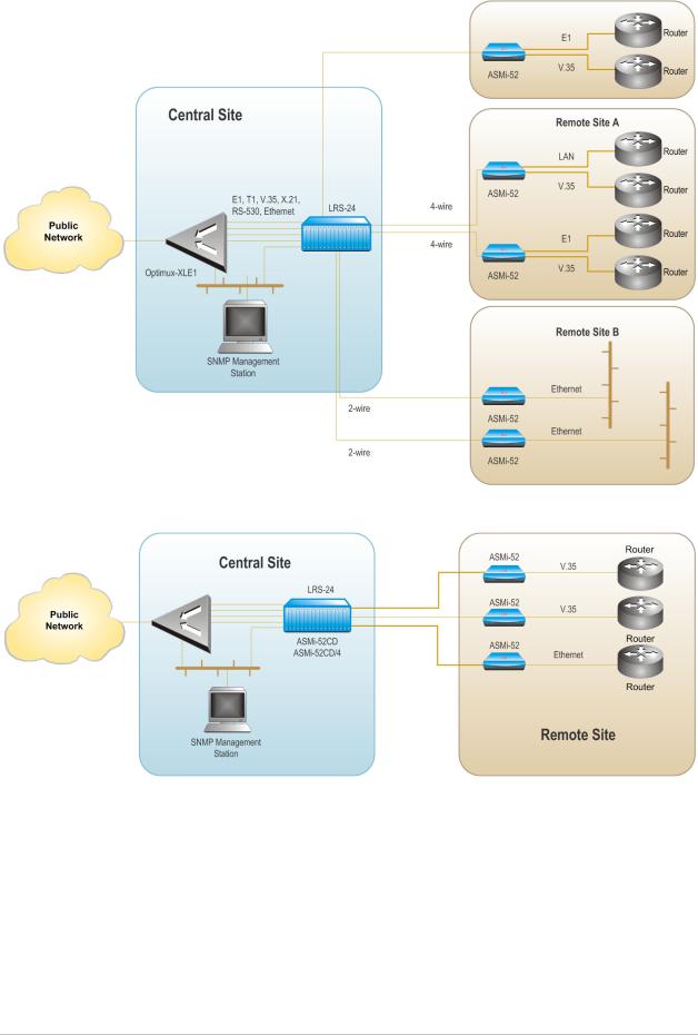
Figure 1-1 illustrates a typical ASMi-52 application, in which standalone modems operate opposite each other. Figure 1-2 shows ASMi-52 units operating opposite a centrally located DXC rack. Figure 1-3 shows ASMi-52 modems operating opposite a centrally located LRS-24 rack.
The following multiplexer applications are supported:
•A multiplexer unit opposite the same type of multiplexer unit
•A DXC opposite multiplexer units (the multiplexer unit is a CPE), where the DXC supports a multiplexer (the CPE is the receive clock source)
•A multiplexer unit configured as a single unit opposite a single unit (where a multiplexer unit is configured as a single unit)
•A multiplexer unit opposite an E1 unit, where the single or multiplexer unit is configured as an E1 single unit.
Figure 1-1. Standalone Modem Application
|
1-2 |
Overview |
ASMi-52 Ver. 2.5 |
|
Installation and Operation Manual |
Chapter 1 Introduction |
Figure 1-2. ASMi-52 Modems Operating Opposite a Centrally Located LRS-24 Rack
Figure 1-3. ASMi-52 Modems Operating opposite ASMi-52CD Cards
|
ASMi-52 Ver. 2.5 |
Overview |
1-3 |

|
Chapter 1 Introduction |
Installation and Operation Manual |
Functionality
ASMi-52 can be configured to operate in a CO (central office) or CPE (customer premises equipment) mode.
Line Interface
ASMi-52 extends the range of data transmission over 2/4-wire lines up to 7.0 km (4.3 miles), by employing SHDSL TC-PAM technology. ASMi-52 operation complies with the requirements of the ITU-T G.991.2 standard. In addition, 4-wire ASMi-52 units can be configured to operate over 2-wire lines.
Table 1-1 lists typical ASMi-52 ranges over 2/4-wire 26 AWG line.
Table 1-1. Typical Ranges (26 AWG)
|
Data Rate |
2-wire |
4-wire |
||||
|
[kbps] |
[km] |
[miles] |
[km] |
[miles] |
||
|
64 |
7.5 |
4.6 |
— |
— |
||
|
128 |
7.0 |
4.3 |
7.1 |
4.4 |
||
|
256 |
6.7 |
4.1 |
6.8 |
4.2 |
||
|
384 |
6.5 |
4.0 |
6.7 |
4.1 |
||
|
512 |
6.3 |
3.9 |
6.6 |
4.1 |
||
|
1024 |
5.3 |
3.3 |
6.0 |
3.7 |
||
|
1536 |
5.0 |
3.1 |
5.6 |
3.5 |
||
|
2048 |
4.5 |
2.8 |
4.7 |
2.9 |
||
|
2304 |
4.2 |
2.6 |
4.5 |
2.8 |
||
|
4096 |
– |
– |
3.7 |
2.3 |
||
|
4608 |
– |
– |
3.0 |
1.8 |
||
The typical ranges are based on error-free lab tests without noise. ASMi-52CD/4W operates at data rates up to 4608 kbps, depending on internal or external clock.
|
1-4 |
Overview |
ASMi-52 Ver. 2.5 |
![]()
|
Installation and Operation Manual |
Chapter 1 Introduction |
DTE Interface
ASMi-52 supports the following DTE interfaces:
•X.21
•V.35
•RS-530
•E1, as per G.704
•T1
•Ethernet/Fast Ethernet bridge with VLAN support (combined with management LAN port)
•IR-IP (IP router).
When ASMi-52 is ordered only with the 10/100BaseT port, it can be used to transfer user and management data.
Note An unbalanced E1 interface is provided via an adapter cable (CBL-RJ-45/2BNC/E1). The impedance conversion (120Ω to 75Ω) is performed by ASMi-52 automatically when the adapter cable connection is detected.
ASMi-52 supports multiple data rates between the range of 64 kbps and 4608 kbps. The data rate depends on the following factors:
•Unit rate mode (regular or low speed)
•Line interface type (2-wire or 4-wire)
•DTE interface type of the local and remote units (serial or E1/T1)
•Clock mode (internal or external)
•Single or multiplexed.
Table 1-2 and Table 1-3 detail the ASMi-52 data rates with the possible combinations of rate mode types, line/DTE interface types, and clock modes.
|
ASMi-52 Ver. 2.5 |
Overview |
1-5 |

Chapter 1 Introduction Installation and Operation Manual
Table 1-2. ASMi-52 Data Rates
|
DTE Interface and Clock Mode |
Line Interface |
||
|
Local ASMi-52 |
Remote ASMi-52 |
2-wire |
4-wire |
|
Serial DTE interface, |
Serial DTE interface |
n × 64 kbps (n = 1, 2, … 32, 36) |
n × 128 kbps (n = 1, 2, …32, 36) |
|
internal clock |
|||
|
Serial DTE interface, |
Serial DTE interface |
n × 64 kbps (n = 1, 2, …, 36) |
n × 128 kbps (n = 1, 2, …, 36) |
|
external clock |
|||
|
Serial DTE interface |
E1 DTE interface |
n × 64 kbps (n = 3, 4, …, 32) |
n × 128 kbps (n = 3, 4, …, 16) |
|
E1 DTE interface |
Serial DTE interface |
n × 64 kbps (n = 3, 4, …, 32) |
n × 128 kbps (n = 3, 4, …, 16) |
|
E1 DTE interface |
E1 DTE interface |
n × 64 kbps (n = 1, 2, …, 32) |
n × 64 kbps (n = 1, 2, …, 32) |
|
T1 DTE interface |
T1 DTE interface |
n × 64 kbps (n = 1, 2, …, 24) |
n × 64 kbps (n = 1, 2, …, 24) |
|
Multiplexer |
Serial/E1 DTE |
n × 64 kbps (n = 1, 2, …, 32) |
n × 64 kbps (n = 1, 2, …, 32) |
|
(any) interface |
|||
Table 1-3. ASMi-52 Data Rates (Low Speed Mode)
|
Unit and DTE Interface Type |
Line Interface |
|||
|
Local Unit |
Remote Unit |
2-wire |
4-wire |
|
|
ASMi-52 in low |
n × 64 kbps (n = 1, 2, …, 32) |
n × 64 kbps (n = 1, 2, …, 32) |
||
|
speed mode |
||||
|
ASMi-52 in low |
ASMi-52 with serial |
n × 64 kbps (n = 3, 4, …, 32) |
n × 128 kbps (n = 3, 4, …, 16) |
|
|
speed mode |
DTE interface |
|||
|
ASMi-52 with E1 |
n × 64 kbps (n = 1, 2, …, 32) |
n × 64 kbps (n = 1, 2, …, 32) |
||
|
DTE interface |
||||
|
Note |
The data rates for a multiplexer modem in Table 1-2 include the entire data rates |
|||
|
sum for all the interfaces. |
|
1-6 |
Overview |
ASMi-52 Ver. 2.5 |

Installation and Operation Manual Chapter 1 Introduction
Multiplexer Applications
Notes • The multiplexer unit cannot be configured as a device with LAN only port. It must have a DTE or IR port.
•The hardware of a single unit-based product with a LAN port manager is different from that of a multiplexer-based product.
The hardware has different options for the modem to work as a multiplexer.
Table 1-4 shows all the available multiplexer combinations that can be used.
|
Note |
Software for a multiplexer version is available but is not transferable to a single port |
||||||||||||||||||||||
|
unit. |
|||||||||||||||||||||||
|
Table 1-4. Possible Multiplexer Applications |
|||||||||||||||||||||||
|
CO/CPE |
E1 |
Serial DTE |
LAN |
E1+Serial DTE |
E1+LAN |
Serial |
|||||||||||||||||
|
DTE+LAN |
|||||||||||||||||||||||
|
E1↔E1 |
E1↔E1 |
E1↔Serial DTE |
|||||||||||||||||||||
|
E1 |
E1↔E1 |
E1↔Serial DTE |
E1↔LAN |
E1↔Serial DTE |
|||||||||||||||||||
|
E1↔E1+Serial |
E1↔E1+LAN |
E1↔Serial |
|||||||||||||||||||||
|
DTE |
DTE+LAN |
||||||||||||||||||||||
|
Serial DTE↔E1 |
Serial DTE↔E1 |
Serial DTE↔ |
|||||||||||||||||||||
|
Serial |
Serial DTE↔E1 |
Serial DTE↔ |
Serial |
Serial DTE |
|||||||||||||||||||
|
Serial DTE |
DTE↔LAN |
||||||||||||||||||||||
|
DTE |
Serial DTE↔ |
||||||||||||||||||||||
|
Serial DTE |
|||||||||||||||||||||||
|
LAN↔Serial |
LAN↔E1 |
LAN↔E1 |
LAN↔Serial |
||||||||||||||||||||
|
LAN↔E1 |
LAN↔LAN |
DTE |
|||||||||||||||||||||
|
LAN |
|||||||||||||||||||||||
|
DTE |
LAN↔Serial |
||||||||||||||||||||||
|
DTE |
|||||||||||||||||||||||
|
E1↔E1 |
E1↔Serial DTE |
E1↔LAN |
E1↔ E1+Serial |
E1↔E1 |
E1↔Serial DTE |
||||||||||||||||||
|
DTE |
|||||||||||||||||||||||
|
Serial DTE↔E1 |
Serial DTE |
V.35↔LAN |
E1↔E1 |
||||||||||||||||||||
|
↔Serial DTE |
|||||||||||||||||||||||
|
E1+Serial |
E1↔Serial DTE |
E1↔E1+LAN |
E1↔Serial |
||||||||||||||||||||
|
DTE↔E1 |
DTE+LAN |
||||||||||||||||||||||
|
E1+Serial |
Serial DTE↔E1 |
Serial DTE↔E1 |
Serial DTE↔ |
||||||||||||||||||||
|
Serial DTE |
|||||||||||||||||||||||
|
DTE |
|||||||||||||||||||||||
|
Serial DTE↔ |
|||||||||||||||||||||||
|
Serial DTE |
|||||||||||||||||||||||
|
E1+Serial |
|||||||||||||||||||||||
|
DTE↔E1 |
|||||||||||||||||||||||
|
E1+Serial DTE |
E1+Serial |
||||||||||||||||||||||
|
↔E1+Serial |
|||||||||||||||||||||||
|
DTE↔E1 |
|||||||||||||||||||||||
|
DTE |
|||||||||||||||||||||||
|
ASMi-52 Ver. 2.5 |
Overview |
1-7 |

Chapter 1 Introduction Installation and Operation Manual
Table 1-4. Possible Multiplexer Applications (Cont.)
|
CO/CPE |
E1 |
Serial DTE |
LAN |
E1+Serial DTE |
E1+LAN |
Serial |
||||||||||||||
|
DTE+LAN |
||||||||||||||||||||
|
E1↔E1 |
E1↔Serial DTE |
E1↔LAN |
E1↔E1+Serial |
E1↔E1 |
E1↔Serial DTE |
|||||||||||||||
|
DTE |
||||||||||||||||||||
|
E1+LAN↔E1 |
E1↔E1 |
|||||||||||||||||||
|
E1+LAN |
E1↔Serial DTE |
E1↔E1+LAN |
E1↔Serial |
|||||||||||||||||
|
DTE+LAN |
||||||||||||||||||||
|
E1+LAN↔E1 |
E1+LAN↔E1 |
|||||||||||||||||||
|
E1+LAN↔ |
||||||||||||||||||||
|
E1+LAN |
||||||||||||||||||||
|
Serial DTE↔E1 |
Serial DTE↔ |
Serial |
Serial DTE↔E1 |
Serial DTE |
||||||||||||||||
|
Serial DTE |
DTE↔LAN |
↔Serial DTE |
||||||||||||||||||
|
Serial DTE+ |
Serial DTE↔E1 |
|||||||||||||||||||
|
LAN↔E1 |
||||||||||||||||||||
|
Serial |
Serial DTE↔ |
|||||||||||||||||||
|
Serial DTE |
||||||||||||||||||||
|
DTE+LAN |
||||||||||||||||||||
|
Serial DTE+ |
Serial DTE+ |
|||||||||||||||||||
|
LAN↔E1 |
LAN↔E1 |
|||||||||||||||||||
|
Serial DTE |
||||||||||||||||||||
|
+LAN↔Serial |
||||||||||||||||||||
|
DTE +LAN |
||||||||||||||||||||
|
DXC |
DXC↔E1+ |
DXC↔E1 |
DXC↔Serial |
|||||||||||||||||
|
Serial DTE |
+LAN |
DTE+LAN |
||||||||||||||||||
|
LRS-24 |
LRS-24↔ |
LRS-24↔ |
LRS-24↔Serial |
|||||||||||||||||
|
E1+Serial DTE |
E1+LAN |
DTE+LAN |
||||||||||||||||||
Serial DTE = V.35, X.21, RS-530, IR-IP
The following are multiplexer conditions when working with the ASMi-52 unit:
•E1+Serial DTE can work as an ‘E1 port only’.
•E1+LAN can work as an ‘E1 port only’.
•LAN+Serial DTE can work as a ‘Serial DTE port only’.
•E1+Ethernet and Serial DTE+Ethernet can be configured as a single port only (‘E1 only’ or ‘Serial DTE only’) while the Ethernet port operates as a management port only.
ASMi-52 E1 or Serial DTE units with a LAN management port previously released with software versions earlier than version 2.5 cannot operate as a multiplexer unit (E1+LAN, Serial DTE+LAN) with version 2.5 due to hardware differences.
Timing
ASMi-52 supports three clock modes:
•Internal, derived from its internal oscillator (CO mode)
•External, supplied by the attached DTE
|
1-8 |
Overview |
ASMi-52 Ver. 2.5 |

|
Installation and Operation Manual |
Chapter 1 Introduction |
•Receive, recovered from the received line signal (CPE mode).
Management
ASMi-52 supports the following management options:
•ASCII terminal or Easy Config hand-held device via V.24/RS-232 terminal port
•Telnet via a dedicated 10/100BaseT port
•SNMP network management (RADview) via a dedicated 10/100BaseT port
•PC, running a Web browsing application (ConfiguRAD)
•Inband management via a dedicated timeslot (units with E1/T1 interface only).
EOC
ASMi-52 provides an inband management channel (EOC) for end-to-end system management and supervision. This management channel uses SHDSL overhead bits and operates without interfering with data transmission.
ConfiguRAD
ConfiguRAD is a user-friendly Web-based terminal management system used for remote device configuration and maintenance. It is embedded in ASMi-52 and provided at no extra cost. ConfiguRAD can be run from any standard Web browser.
Dial-In
The V.24 terminal port supports a dial-up modem connection for remote management of ASMi-52 over telephone lines.
Dial-Out
The V.24 terminal port supports alarm dial-out.
Diagnostics
ASMi-52 supports activation of the following:
•Local loopback
•Remote loopback
•Remote loopback at the SHDSL repeater (activated from the local unit)
•Internal Bert (multiplexer units only) vs. multiplexer.
All tests can be activated from the local unit or from the remote unit.
ASMi-52 includes an internal Bit Error Rate Tester (BERT) for complete testing of the local and remote modem and the link quality without any need for an external test equipment. ASMi-52 runs an internal pseudo-random 511-bit test pattern in accordance with the ITU V.52 standard.
Real time alarms provide information on the system status, indicating management failure, synchronization loss and other conditions.
|
ASMi-52 Ver. 2.5 |
Overview |
1-9 |

|
Chapter 1 Introduction |
Installation and Operation Manual |
Statistics Collection
ASMi-52 supports SHDSL and E1/T1 statistics collection.
Alarm Reporting
ASMi-52 alarms are relayed via a dedicated 6-pin terminal block connector.
SHDSL Repeaters
Up to eight SHDSL repeaters can be installed in line to increase the operation range of the modem. ASMi-52 provides basic management of the repeaters.
Note
SHDSL repeaters do not support ASMi-52 T1 products.
1.2Physical Description
Figure 1-4 shows a 3D view of the ASMi-52 unit in the plastic enclosure.
Figure 1-4. ASMi-52, 3D View
The front panel includes several LEDs, which display the status of power, data flow and provide diagnostics. For a detailed description of the front panel, see
Chapter 3.
The rear panel includes an AC/DC power connector, a DTE connector, a line connector, a 10/100BaseT port, a V.24 terminal connector, and an alarm relay port. The ASMi-52 rear panel is described in greater detail in Chapter 2.
1.3Functional Description
This section provides a functional description of ASMi-52 in the form of block diagrams (Figure 1-5 and Figure 1-6).
|
1-10 |
Functional Description |
ASMi-52 Ver. 2.5 |

|
Installation and Operation Manual |
Chapter 1 Introduction |
Internal
Oscillator
|
Data & Clock |
||||
|
DTE |
Modem Glue |
SHDSL |
||
|
Interface |
Control Signals |
Logic |
Line Interface |
|
|
CPU Data Bus |
|
Power |
10/100BaseT |
|||
|
CPU |
Management |
|||
|
Supply |
||||
|
Port |
||||
LEDs and Terminal Interface
Figure 1-5. ASMi-52/4W with V.35 Interface and 10/100BaseT Management Port
Figure 1-6. ASMi-52/4W with Framed E1 Interface and 10/100BaseT Management Port
The ASMi-52 modem consists of the following major modules:
DTE interface – Prepares the digital data coming from the DTE into a data stream for modem glue logic. In addition, it translates the data from the modem glue logic into digital data to be sent to the DTE.
|
ASMi-52 Ver. 2.5 |
Functional Description |
1-11 |

|
Chapter 1 Introduction |
Installation and Operation Manual |
Internal oscillator – Serves as a source of internal clock for the ASMi-52 unit.
Modem glue logic module – Processes the data from/to the SHDSL interface module.
SHDSL line interface – Translates the received and transmitted data from the line to the DTE interface.
Power supply – Provides 2.5V, 3.3V, 5V and -5V to the ASMi-52 internal elements.
CPU – Controls the ASMi-52 operation.
10/100BaseT management port – Provides LAN connection to the SNMP management station or Telnet host.
LEDs and terminal interface – Provides modem status information via LED indicators on the front panel, and communicates with the supervisory terminal.
1.4Technical Specifications
|
Line Interface |
Type |
|
Line Coding |
|
|
Range |
|
|
Impedance |
|
|
Connectors |
|
|
Standard |
|
|
E1 Jitter |
|
|
Performance |
|
|
Protection |
|
|
DTE Interface |
Data Rate |
Coding
Line Impedance
2/4-wire unconditioned dedicated line (twisted pair) TC-PAM
See Table 1-1
135Ω
•ASMi-52: RJ-45
•ASMi-52CD: Two RJ-45
ITU-T 991.2, ETSI 101 524
As per ITU G.823
ITU K.21, UL1950
Depends on the DTE/line interface type and clock mode (see Table 1-2 and Table 1-3)
•2-wire (external clock): 64–2304 kbps,
2-wire (internal clock): 64–2048, 2304 kbps
•4-wire (external clock): 64–4608 kbps,
4-wire (internal clock): 64–4096, 4608 kbps
•ASMi-52CD/4W:
(external clock): 128-4608 kbps (internal clock): 128-4096, 4608 kbps
•E1: HDB3
•T1: B8ZS or AMI
•E1: 120Ω, balanced
75Ω, unbalanced (via adapter cable)
|
1-12 |
Technical Specifications |
ASMi-52 Ver. 2.5 |

|
Installation and Operation Manual |
Chapter 1 Introduction |
Connector Type
|
Management |
V.24/RS-232 |
|
Ports |
Control Port |
|
Interface |
|
|
Connector |
|
|
Format |
|
|
Baud Rate |
|
|
Ethernet Port |
|
|
Interface |
|
|
Connector |
|
|
Timing |
Diagnostics Loopbacks
Performance
Monitoring
•T1: 100Ω, balanced
•X.21: 15-pin, D-type, female
•V.35 – 34-pin, female
•RS-530 – 25-pin, D-type, female
•G.703/G.704 E1 – RJ-45, balanced or unbalanced (via adapter cable)
•T1 – RJ-45
•IR-IP (IP router) – RJ-45
•Ethernet (10/100BaseT bridge with VLAN support) – RJ-45
V.24/RS-232 DTE 9-pin D-type, female Asynchronous
9.6 to 115.2 kbps
10/100BaseT RJ-45 shielded
Derived from three alternative sources:
•Internal oscillator
•External, from the attached DTE
•Receive, derived from the received signal
ITU V.54:
•Local analog loopback, activated via the management software or by the DTE interface signal (V.35 and RS530 only)
•Remote digital loopback, activated via the management software or by the DTE interface signal (V.35 and RS-530 only)
•Remote loopback at the SHDSL repeater
•SHDSL statistics collection
•E1 with CRC-4 or T1 with ESF framing per ITU G.706
•E1 without CRC-4 or T1 with SF framing bipolar violations (BPV)
|
ASMi-52 Ver. 2.5 |
Technical Specifications |
1-13 |

|
Chapter 1 Introduction |
Installation and Operation Manual |
|
|
Alarm Relay |
Operation |
Normally Open and Normally Closed, using different |
|
pins |
||
|
Connector |
Terminal block, 6-pin |
|
|
Indicators |
PWR (green) |
Power |
|
TEST (red) |
Test |
|
|
SYNC A/B |
Synchronization of DSL line |
|
|
(green/red) |
||
|
DATA (yellow) |
Data Transfer (except E1 and T1 options) |
|
|
E1/T1 SYNC (red) |
Loss of E1/T1 synchronization (E1 and T1 options only) |
|
|
AIS (yellow) |
“All 1s string” is received (E1 or T1 interface only) |
|
|
ALM (red) |
Alarm |
|
|
Physical |
Plastic Enclosure |
|
|
Height |
43.7 mm (1.7 in) |
|
|
Width |
217 mm (8.5 in) |
|
|
Depth |
170 mm (6.7 in) |
|
|
Weight |
0.5 kg (1.1 lb) |
|
|
Metal Enclosure |
||
|
Height |
47.3 mm (1.8 in) |
|
|
Width |
215 mm (8.4 in) |
|
|
Depth |
147 mm (5.8 in) |
|
|
Weight |
0.7 kg (1.5 lb) |
|
|
Rail-Mount Metal |
||
|
Enclosure |
||
|
Height |
150 mm (5.9 in) |
|
|
Width |
70 mm (2.7 in) |
|
|
Depth |
160 mm (6.3 in) |
|
|
Weight |
0.75 kg (1.65 lb) |
|
|
Power Source |
AC/DC Voltage |
Wide range power supply: |
|
100–240 VAC or -48/60 VDC nominal |
||
|
DC only: |
||
|
24 VDC |
||
|
Power |
2-wire: 6W max |
|
|
Consumption |
4-wire: 7W max |
|
|
1-14 |
Technical Specifications |
ASMi-52 Ver. 2.5 |
![]()
|
Installation and Operation Manual |
Chapter 1 Introduction |
|||||||
|
Environment |
Standalone: |
0 |
to 50 C (32 |
to 122 |
F) |
|||
|
Temperature |
° |
° |
° |
° |
||||
|
Rail-mount: |
−20° to 70°C (−4° to 158°F) |
|||||||
|
Humidity |
Up to 90%, non–condensing |
|||||||
|
Shock |
IEC 60068-2-27 shock 15g, |
|||||||
|
(Rail-Mount) |
11 ms duration, 18 shocks |
|||||||
|
Vibration |
• IEC 60068-2-6 vibration 1 mm |
|||||||
|
(Rail-Mount) |
• 2 – 13.2 Hz, 90 min |
•0.7g, 13.2 – 100 Hz, 90 min.; 3.5 mm, 3 – 9 Hz, 10 cycles
•1 octave/min.; 1g, 9 – 150 Hz
•10 cycles, 1 octave/min
|
ASMi-52 Ver. 2.5 |
Technical Specifications |
1-15 |

|
Chapter 1 Introduction |
Installation and Operation Manual |
|
1-16 |
Technical Specifications |
ASMi-52 Ver. 2.5 |

Chapter 2
Installation and Setup
2.1 Introduction
This chapter describes installation and setup procedures for the standalone ASMi-52 modem.
After installing the unit:
•Refer to Chapter 3 for the operating instructions.
•Refer to Chapter 4 for the detailed system configuration procedures using an ASCII terminal connected to the ASMi-52 control port.
If a problem is encountered, refer to Chapter 5 for test and diagnostic instructions.
Internal settings, adjustment, maintenance, and repairs may be performed only by a skilled technician who is aware of the hazards involved.
 Always observe standard safety precautions during installation, operation, and Warning maintenance of this product.
The ASMi-52 standalone unit is designed for desktop or bench installation and is delivered as a fully assembled unit. No provisions are made for bolting the unit to a tabletop.
To install ASMi-52:
1.Determine the required configuration of ASMi-52, in accordance with your application.
2.Connect the line (see Connecting the Line below).
3.Connect the DTE (see Connecting the DTE Interface below).
4.Connect power to the unit (see Connecting the Power below).
2.2 Site Requirements and Prerequisites
AC-powered ASMi-52 units should be installed within 1.5m (5 ft) of an easily-accessible grounded AC outlet capable of furnishing the voltage in accordance with ASMi-52 nominal supply voltage.
DC-powered ASMi-52 units require a -48 VDC power source, which must be adequately isolated from the main supply.
|
ASMi-52 Ver. 2.5 |
Site Requirements and Prerequisites |
2-1 |

|
Chapter 2 Installation and Setup |
Installation and Operation Manual |
Allow at least 90 cm (36 in) of frontal clearance for operation and maintenance accessibility. Allow at least 10 cm (4 in) clearance at the rear of the unit for signal lines and interface cables.
The ambient operating temperature of ASMi-52 should be 0° to 50°C (32° to 122°F), at a relative humidity of up to 90%, non-condensing.
2.3 Package Contents
The ASMi-52 package includes the following items:
•One ASMi-52 unit
•Technical documentation CD
•Power connection accessories (depending on which power option was ordered):
Power cord (VAC) and AC/DC plug (-48 VDC)
Terminal block kit (24 VDC)
•CBL-RJ45/2BNC/E1 adapter cable for unbalanced E1 interface (if ordered)
•RM-33 rack mount kit for the plastic case unit (if ordered)
•RM-35 rack mount kit for the metal case unit (if ordered)
2.4 Connecting the Interface Cables
Figure 2-1 illustrates the rear panel of ASMi-52 in a plastic enclosure with a 4-wire line interface, E1 DTE interface, user LAN interface, alarm relay port and the control port.
Figure 2-2 illustrates the rear panel of ASMi-52 in a metal enclosure with a 4-wire line interface, the user LAN interface, and the control port.
|
TX |
RX |
LINE |
LINE |
DCE |
||
|
ALARM |
B |
A |
||||
|
1 2 |
4 |
5 |
1 2 |
4 5 |
||
|
LINK |
ACT |
E1/T1 |
SHDSL |
|||
|
CONTROL |
V.35 |
Figure 2-1. ASMi-52 Rear Panel (Plastic Enclosure)
LINE LINE
B A 1 2 
 4 5
4 5
|
LINK |
ACT |
||||||||||
Figure 2-2. ASMi-52 Rear Panel (Metal Enclosure)
|
2-2 |
Connecting the Interface Cables |
ASMi-52 Ver. 2.5 |

|
Installation and Operation Manual |
Chapter 2 Installation and Setup |
Connecting the Line
The ASMi-52 line interface terminates in an 8-pin RJ-45 connector.
To connect the line connector:
•Connect the line cable to the RJ-45 connector designated SHDSL.
Connecting the DTE Interface
The ASMi-52 DTE interface provides interface for input/output data, clock reference and control signals between the modem and the DTE. The DTE interface terminates in one of the following connectors:
•X.21 – 15-pin, D-type, female
•V.35 – 34-pin, female
•RS-530 – 25-pin, D-type, female
•Balanced E1 – RJ-45
•Unbalanced E1 – two BNC coax via adapter cable
•Balanced T1 – RJ-45
•IR-IP – RJ-45
•ETH – RJ-45.
For a detailed description of the IR-IP interface module, refer to Appendix B.
The E1/T1 port is intended for an intra-building non-exposed plant only.
Warning
To connect the DTE interface:
•Connect the DTE to the appropriate rear panel DTE interface connector of the ASMi-52 modem.
Appendix A specifies the DTE connector pinouts.
Connecting the Alarm Relay Connector
To connect the alarm relay:
•Connect the external alarm device to the rear panel terminal block connector designated ALARM. Refer to Appendix A for the connector pinout and alarm functions.
2.5 Connecting the Power Cables
ASMi-52 is equipped with a dual input AC/DC power supply. AC or DC power is supplied to ASMi-52 via a standard 3-prong power input connector on the rear panel (see Figure 2-1).
|
ASMi-52 Ver. 2.5 |
Connecting the Power Cables |
2-3 |

Chapter 2 Installation and Setup Installation and Operation Manual
Before connecting this unit to a power source and connecting or disconnecting any other cable, the protective earth terminals of this unit must be connected
to the protective ground conductor of the mains (AC or DC) power cord. If you
Warning are using an extension cord (power cable) make sure it is grounded as well. Any interruption of the protective (grounding) conductor (inside or outside the
instrument) or disconnecting of the protective earth terminal can make this unit dangerous. Intentional interruption is prohibited.
Connecting AC Power
AC power should be supplied through the 1.5m (5 ft) standard power cable terminated by a standard 3-prong plug. The cable is provided with the unit.
To connect AC power:
1.Connect the power cable to the power connector on the ASMi-52 rear panel.
2.Connect the power cable to the mains outlet.
The unit turns on automatically upon connection to the mains.
Connecting DC Power
DC power is supplied to ASMi-52 via a compatible AC/DC plug for attaching DC power supply lines.
To connect DC power:
•Refer to the DC power supply connection supplement.
|
2-4 |
Connecting the Power Cables |
ASMi-52 Ver. 2.5 |

Chapter 3
Operation
This chapter provides the following information for the ASMi-52 modem:
•ASMi-52 front-panel indicators
•Operating procedures (turn-on, front-panel indications, performance monitoring and turn-off)
•ASMi-52 default settings.
Installation procedures given in Chapter 2 must be completed and checked before attempting to operate ASMi-52.
3.1 Turning On ASMi-52
To turn on ASMi-52:
•Connect the power cord to the mains.
The PWR indicator lights up and remains lit as long as ASMi-52 is receiving power.
ASMi-52 requires no operator attention once installed, with the exception of occasional monitoring of front panel indicators. Intervention is only required when ASMi-52 must be configured to its operational requirements, or diagnostic tests are performed.
3.2 Controls and Indicators
The front and rear panels of ASMi-52 include a series of LED indicators that show the current operating status of the unit.
Figure 3-1 shows the front panel of the 2-wire ASMi-52 unit in a plastic enclosure with an E1 interface. Figure 3-2, Figure 3-3, Figure 3-4, Figure 3-5, Figure 3-6, and
Figure 3-7 illustrate the front panel options for the ASMi-52 4-wire unit in its plastic enclosure with E1/T1, IR (DTE Serial Data), and Ethernet interfaces.
Table 3-1 lists and describes the front panel indicators. Table 3-2 lists and describes the rear panel indicators.
|
ASMi-52 Ver. 2.5 |
Controls and Indicators |
3-1 |

|
Chapter 3 Operation |
Installation and Operation Manual |
ASMi-52
Figure 3-1. ASMi-52 Front Panel, E1 Interface (2 Wire)
Figure 3-2. ASMi-52 Front Panel, E1 Interface (4 Wire)
Figure 3-3. ASMi-52 Front Panel, T1 Interface (4 Wire)
ASMi-52
Figure 3-4. ASMi-52 Front Panel, DTE Serial Interface (4 Wire)
Figure 3-5. ASMi-52 Front Panel, E1+DTE Serial Interface (4 Wire)
Figure 3-6. ASMi-52 Front Panel, E1+Ethernet Interface (4 Wire)
Figure 3-7. ASMi-52 Front Panel, DTE Serial Interface+Ethernet (4 Wire)
|
3-2 |
Controls and Indicators |
ASMi-52 Ver. 2.5 |

Installation and Operation Manual Chapter 3 Operation
|
Table 3-1. ASMi-52 Front Panel LEDs |
|
|
Name |
Function |
|
PWR (green) |
On – Power is ON |
|
TST (red) |
On – A loopback test is active in a local or remote unit |
|
SYNC A |
On (red) – Link A is not synchronized |
|
(red/green) |
On (green) – Link A is synchronized |
|
Blinks – The line is connected properly and the |
|
|
synchronization process is taking place |
SYNC B (red/green)
On (red) – Link B is not synchronized
On (green) – Link B is synchronized
Blinking – The line B is connected properly and the synchronization process is taking place
|
AIS (yellow) |
On – “All 1s string” is received at the E1 interface |
|
YELLOW (yellow) |
On – “All 1s string” is received at the T1 interface |
|
E1/T1 SYNC (red) |
On – Loss of E1 or T1 synchronization |
|
DATA (yellow) |
Blinking – Data is being transferred |
|
ALM (red) |
On – An alarm enters the buffer of local or remote unit |
|
ACT (yellow) |
For Ethernet, blinks according to the Ethernet traffic activity |
|
(10/100BaseT connector), available only when multiplexed |
|
|
Table 3-2. ASMi-52 Rear Panel LEDs |
|
|
Name |
Function |
|
ACT (yellow) |
Blinks according to the Ethernet traffic activity (10/100BaseT |
|
connector) |
|
|
LINK (green) |
On – Good link integrity (10/100BaseT connector) |
Normal Indications
Upon turning on ASMi-52, the PWR LED in the front panel lights to indicate that ASMi-52 is on. Table 3-3 shows the correct status of the indicators a few seconds after the units were synchronized.
Table 3-3. ASMi-52 Indicator Status
|
Indicator |
Status |
|
PWR |
On |
|
TST |
Off |
|
ALM |
Off |
|
SYNC |
On (green) |
If the above LED indications do not appear following initial power activation, refer to Chapter 5 for the diagnostic test instructions.
|
ASMi-52 Ver. 2.5 |
Controls and Indicators |
3-3 |

|
Chapter 3 Operation |
Installation and Operation Manual |
|
3.3 Default Settings
ASMi-52 is managed by an ASCII terminal or a PC running a terminal emulation program via a menu-driven embedded software. Table 3-4 lists the default settings of the ASMi-52 configuration parameters.
|
Table 3-4. Default Settings |
||
|
Parameter |
Default Value |
|
|
System |
||
|
Clock |
Internal |
|
|
Sys contact |
– |
|
|
Sys location |
– |
|
|
Sys name |
– |
|
|
Host IP address |
0.0.0.0 |
|
|
Host IP mask |
0.0.0.0 |
|
|
Host default gateway |
0.0.0.0 |
|
|
Read community |
public |
|
|
Write community |
public |
|
|
Trap community |
public |
|
|
SNMP allowed |
Access allowed |
|
|
Telnet allowed |
Access allowed |
|
|
WEB allowed |
Access allowed |
|
|
DTS IP address |
0.0.0.0 |
|
|
DTS IP mask |
0.0.0.0 |
|
|
LAN Configuration |
||
|
LAN operation mode |
Transparent |
|
|
Encapsulation CRC |
No |
|
|
Bridging Mode |
Access only |
|
|
Aging Timeout |
10 |
|
|
Autonegotiation |
Enable |
|
|
LAN Rate |
1. Single |
2-wire – 192 kbps |
|
4-wire – 384 kbps |
||
|
2. E1+LAN |
N/A (0 kbps) |
|
|
3. Serial DTE+LAN |
N/A (0 kbps) |
|
|
Max AutoNeg Capability |
100BaseT full duplex mode |
|
|
3-4 |
Default Settings |
ASMi-52 Ver. 2.5 |
![]()
|
Installation and Operation Manual |
Chapter 3 Operation |
||
|
Parameter |
Default Value |
||
|
Control Port |
|||
|
Control port rate |
9600 bps |
||
|
Data |
8 |
||
|
Parity |
None |
||
|
Interface |
DCE |
||
|
CTS |
=RTS |
||
|
DSR |
ON |
||
|
Port control mode |
Terminal |
||
|
User name |
– |
||
|
Password |
1234 |
||
|
Pop alarm |
OFF |
||
|
Security timeout |
10 min |
||
|
Call Out Mode |
None |
||
|
Number of retries |
1 |
||
|
Wait for connect |
30 sec |
||
|
Dial mode |
Tone |
||
|
Alternate number mode |
Disable |
||
|
Primary number |
– |
||
|
Alternate number |
– |
||
|
SHDSL Interface |
|||
|
Transmission mode |
Annex B |
||
|
Power backoff |
Enable |
||
|
Snext margin |
Disable |
||
|
Current margin |
Disable |
||
|
Asym PSD |
Symmetrical |
||
|
Line prob* |
Fixed rate |
||
|
Units with a 4-wire line interface support only |
|||
|
fixed rate. |
|||
|
Configured wire |
ASMi-52 2-wire = 2w |
||
|
ASMi-52 4-wire = 4w |
|||
|
Loop attenuation threshold |
0 |
||
|
SNR margin threshold |
0 |
||
|
ASMi-52 Ver. 2.5 |
Default Settings |
3-5 |

|
Chapter 3 Operation |
Installation and Operation Manual |
|||
|
Parameter |
Default Value |
|||
|
Serial DTE Interface |
||||
|
Rate |
Single: |
|||
|
2-wire – 192 kbps |
||||
|
4-wire – 384 kbps |
||||
|
Multiplexer: |
||||
|
1. E1+Serial DTE, N/A, 0 kbps |
||||
|
2. LAN+Serial DTE: |
2-wire – 192 kbps |
|||
|
4-wire – 384 kbps |
||||
|
LLB from DTE |
Disable |
|||
|
RLB from DTE |
Disable |
|||
|
E1/E1+Ethernet/E1+Serial DTE Interface |
||||
|
Framed mode |
Unframed |
|||
|
Sync |
CCITT |
|||
|
CRC-4 |
No |
|||
|
Idle Code |
ff |
|||
|
Units identical settings |
Yes |
|||
|
T1 Interface |
||||
|
Framed mode |
Unframed |
|||
|
Line code |
B8ZS |
|||
|
Receive gain |
Long |
|||
|
Interface |
DSU |
|||
|
Transmit signal mask |
0 feet |
|||
|
Fbit configuration |
Transparent |
|||
|
Sync mode |
Fast (after 1 sec) |
|||
|
Idle code |
Ff |
|||
|
Units identical set |
Yes |
|||
3.4 Configuration Alternatives
After installation, ASMi-52 can be reconfigured using different ports and applications:
•Local out-of-band management via an ASCII terminal or the Easy Config device connected to the RS-232 port. Usually, preliminary configuration of the system parameters is performed via an ASCII terminal. Once the ASMi-52 host IP parameters are set, it is possible to access it via Telnet, ConfiguRAD, or RADview-Lite for further configuration.
|
3-6 |
Configuration Alternatives |
ASMi-52 Ver. 2.5 |

|
Installation and Operation Manual |
Chapter 3 Operation |
•Remote management via out-of-band 10/100BaseT port or dedicated timeslot. Remote management is performed using Telnet, or ConfiguRAD (RAD’s Web-based application), or RADview (RAD’s SNMP-based management system).
Managing ASMi-52 via a Terminal Port
This section describes how to prepare ASMi-52 and the supervisory terminal for a control session.
Control Port Interface Characteristics
ASMi-52 includes a V.24 (RS-232) asynchronous DCE port, designated as CONTROL and terminating in a 9-pin D-type female connector. The control port continuously monitors the incoming data stream and immediately responds to any input string received through this port.
The terminal can be connected either directly to the ASMi-52 control port, or through a modem or any other type of full-duplex data link. The ASMi-52 control port interface type must be set in accordance with the connection method, as follows:
•DCE – direct connection to terminals. Since terminals usually have DTE interfaces, the connection to the port is made by means of a cable.
•DTE – connection through a modem or data link. In this case, you need a cross-cable (also called a null modem cable) to connect to the CONTROL connector.
The ASMi-52 control port can be configured to communicate at the following rates: 9.6, 19.2, 38.4, 57.6, or 115.2 kbps.
The word format consists of one stop bit, 8 data bits, and no parity.
Note ASMi-52 can also be managed via a hand-held control device, Easy Config. Refer to Appendix C for detailed description of the device.
Preparing the Terminal
Any standard ASCII terminal (a “dumb” terminal or a personal computer running a terminal emulation application) equipped with a V.24 (RS-232) communication interface can be used to configure ASMi-52. Appendix A details the pin assignments and control signal directions of the ASMi-52 control connector.
Data Terminal Ready (DTR)
When connected and turned on, the terminal sets the DTR line ON (active) to gain control over ASMi-52 and starts a configuration or monitoring session.
Initiating a Control Session
To initiate a control session:
1.Connect the terminal cable to the CONTROL connector of ASMi-52.
2.Turn the control terminal on.
|
ASMi-52 Ver. 2.5 |
Configuration Alternatives |
3-7 |

|
Chapter 3 Operation |
Installation and Operation Manual |
3.Configure the terminal to the default communication parameters: 9.6 kbps, one start bit, eight data bits, no parity, one stop bit, VT100 emulation.
4.Select the full duplex mode.
5.Turn the terminal echo off.
6.Disable any type of flow control.
You are now ready to start a control session.
Navigating the Management Menus
This section provides a general description of the software menu operation and conventions for navigating the menus.
Choosing Options
To choose an option:
• Type the number corresponding to the option, and press <Enter>. The screen for the selected option is displayed.
•
When a menu option has only two values, typing the option number and pressing <Enter> will scroll between the available values.
Some of the ASMi-52 menus have a ‘Save’ option. When choosing options from these menus, confirm your choice by typing the number corresponding to the ‘Save’ option, otherwise your entry will be ignored.
Correcting Entries
To correct an erroneous entry:
•Press <Backspace> to clear the error, then enter the correct characters. or
Press <Esc> to exit the current menu, and then return to the menu to re-enter the required value.
Navigating Data Forms
Some of the ASMi-52 management software screens are data forms, which are bigger than regular menus and require scrolling to navigate between parameters. For example, the Inventory screen or Manager List menu are considered data forms.
Use the following keys (case-sensitive) for the data form navigation:
•L – move left, l – scroll left,
•R – move right, r – scroll right
•U – move up, u – scroll up
•D – move down, d – scroll down
•<Tab> – select next changeable cell.
•
You can display these navigation keys by typing <?> from a data form.
|
3-8 |
Configuration Alternatives |
ASMi-52 Ver. 2.5 |

|
Installation and Operation Manual |
Chapter 3 Operation |
Managing ASMi-52 via Ethernet Port
ASMi-52 is equipped with an Ethernet/Fast Ethernet port (10/100BaseT) which enables communication with ASMi-52 management subsystem using the IP protocol (see Figure 3-9). The Ethernet management port is configured for a LAN cross-over connection.
To prepare ASMi-52 for network management:
1.Connect a LAN network management station to the ASMi-52 Ethernet port designated 10/100BaseT.
2.Configure the host IP parameters of the ASMi-52 unit via an ASCII terminal.
3.Run an SNMP management application, such as RAD’s RADview, open a Telnet session, or manage ASMi-52 via ConfiguRAD.
To start the ConfiguRAD session:
1.Start a Web browser.
2.Disable any pop-up blocking software, such as the Google Popup Blocker.
3.Enter the IP address of the ASMi-52 in the address field of the browser in the following format: http://<IP address> and then press <Enter> to command the browser to connect (IP address stands for the actual ASMi-52 IP address which has to be assigned via an ASCII terminal).
4.In the Login screen, click LOGIN to start the ConfiguRAD management session.
To choose an option:
1.Click a link in the ConfiguRAD screen to display the next menu.
2.Once the target screen is displayed, select a value from the drop-down box.
Figure 3-8. ConfiguRAD Login
Managing ASMi-52 via a Dedicated Timeslot
ASMi-52 modems with E1 or T1 interface can be managed via a dedicated E1/T1 timeslot (DTS) (see Figure 3-9).
The DTS is a management channel that connects directly to the ASMi-52 host using a separate IP interface, i.e., separate IP address and IP mask. If the LAN and dedicated timeslot services are configured to have the same IP, the management
|
ASMi-52 Ver. 2.5 |
Configuration Alternatives |
3-9 |

|
Chapter 3 Operation |
Installation and Operation Manual |
session over the dedicated timeslot has priority over management via the 10/100BaseT port.
1.Connect the E1/T1 line to the ASMi-52 E1 or T1 port.
2.Start a terminal management session and do the following:
Assign an IP address and an IP mask to the dedicated timeslot interface
Enable DTS management
Assign an E1/T1 timeslot for the management traffic.
3.Run an SNMP management application, such as RAD’s RADview, open Telnet session, or manage ASMi-52 via ConfiguRAD.
Figure 3-9. Managing ASMi-52 via LAN Port and a Dedicated Timeslot
Managing ASMi-52 via Web Browser
ConfiguRAD is a Web-based remote access terminal management software. It provides a user-friendly interface for configuring, collecting statistics, and performing diagnostic tests on the ASMi-52 units.
To choose an option:
1.Click a link in the ConfiguRAD screen to display the next menu.
2.Once the target screen is displayed, select a value from the drop-down box or enter a value in a text box.
Some of the ASMi-52 menus have a ‘Save’ option. When choosing options from these menus, you must confirm your choice by selecting ‘Save’, otherwise your entry will be ignored.
At the left-hand bottom corner, ConfiguRAD provides some auxiliary management tools:
•Status – shows the number of users currently managing ASMi-52
|
3-10 |
Configuration Alternatives |
ASMi-52 Ver. 2.5 |

|
Installation and Operation Manual |
Chapter 3 Operation |
•Trace – opens an additional pane for system messages, progress indicators (ping, software and configuration file downloads) and alarms. It is recommended to keep the trace pane open all the time.
•Refresh All – refreshes all screen elements.
Configuration Menus
The following is the menu map of the ASMi-52 management software.
Note Some of the management menu options depend on the type of the DTE interface installed in ASMi-52:
•DTS Configuration (Main menu > Configuration > System Configuration > Management) is available only for the units with E1 or T1 interface.
•LAN Rate (Main menu > Configuration > LAN Configuration > Local LAN Configuration) is available for the units with the user’s 10/100BaseT port.
•Data Rate (Main menu > Configuration > DTE Configuration > DTE Remote Port) is available for the units with a serial DTE interface.
•E1 Configuration (Main menu > Configuration) is available for the units with an E1 local port.
•Figure 3-10 illustrates software menus of the unit that operates with SHDSL repeater in the line.
|
ASMi-52 Ver. 2.5 |
Configuration Alternatives |
3-11 |

|
Chapter 3 Operation |
Installation and Operation Manual |
Figure 3-10. Inventory and Configuration Menus
|
3-12 |
Configuration Alternatives |
ASMi-52 Ver. 2.5 |

|
Installation and Operation Manual |
Chapter 3 Operation |
Figure 3-11. Monitoring, Diagnostics and File Utilities Menus
|
ASMi-52 Ver. 2.5 |
Configuration Alternatives |
3-13 |

|
Chapter 3 Operation |
Installation and Operation Manual |
To end the current session:
•In the Main menu, click Logout or type & in a terminal management screen.
•
•ASMi-52 allows at least four management sessions to be active at a time. If the Web-based management sessions were not ended properly (for example, by closing the Web browser window), you have to wait five minutes before attempting the next log-in. If you try to log in during the five-minute security timeout, ASMi-52 does not allow to proceed to the Main menu, displaying ‘Too Many Users’ message. Likewise, the Web-based management session cannot be initiated, if a terminal or Telnet session is still in progress.
•One session is always reserved as a terminal session from the four available management sessions, the other three sessions can be a ConfiguRAD or Telnet sessions. The four sessions can function at the same time.
3.5 Turning Off ASMi-52
To turn off ASMi-52:
•Remove the power cord from the power source.
|
3-14 |
Turning Off ASMi-52 |
ASMi-52 Ver. 2.5 |
 Loading…

Модемы ASMi-52 и ASMi-52L используют технологию SHDSL с линейным кодом TC PAM-16, позволяющую увеличить дальность цифровых линий связи. Они обеспечивают передачу данных на большие расстояния в диапазоне скоростей до 2.3 Мбит/с по одной медной паре и до 4.6 Мбит/с по двум парам.
-
Работают на нескольких скоростях передачи данных между 2.3 Мбит/с и 4.6 Мбит/с
-
Дальность действия до 10 км
-
Надежная производительность при передаче по некачественным или зашумленным линиям
-
Работает с модулями RAD LRS-24, DXC и Megaplex, а также с оборудованием других производителей
-
Пользовательские порты ASMi-52 могут быть E1, T1, V.35, X.21, RS-530 и 10/100BaseT с мостом или маршрутизатором
-
ASMi-52 с двумя портами может мультиплексировать данные V.35/X.21/RS-530, 10/100BaseT LAN и трафик E1 через SHDSL
-
ASMi-52L поставляется с одним пользовательским портом V.35, X.21 или 10/100BaseT, или со встроенным коммутатором с четырьмя портами Ethernet
-
Автоматическая конфигурация позволяет быстро и легко устанавливать устройство
-
Поставляются и в виде 2/4 модемной карты для стойки 19” LRS-24
ASMi-52 может быть поставлен в версии высшего класса с двумя пользовательскими портами и возможностями мультиплексора. С его помощью можно передавать комбинации трафика V.35/X.21/RS-530, 10/100BaseT и E1 по одному соединению SHDSL с максимальной скоростью 2.3 Мбит/с.
Модель ASMi-52L отличается привлекательной ценой и предназначена для приложений, в которых требуется только один пользовательский порт. Со стороны пользователя устройства поддерживают E1 и T1, V.35, X.21 и RS-530, мост Ethernet и маршрутизатор IP. ASMi-52L поставляется также с четырехпортовым интерфейсом 10/100BaseT с встроенным коммутатором.
Модемы ASMi позволяют увеличить дальность передачи на скорости 2 Мбит/с до 4 км по одной медной паре и еще более — по двум парам. Все модели совместимы с повторителями для 2-х и 4-х проводных линий, например, с RAD S-RPT, для приложений с еще большей дальностью.
Устройства соответствуют стандартам ITU-T G.991.2 и ETSI 101524 для SHDSL. Модемы SHDSL также могут работать в сочетании с модулями SHDSL для устройств DXC и Megaplex. Мониторинг, управление и диагностика местного и удаленного устройства могут осуществляться через порт управления. Соответствие действующим стандартам позволяет использовать модемы ASMi в сочетании с аппаратурой TDM других производителей, поддерживающей стандарт SHDSL.
Модем SHDSL ASMi-52 выпускается в виде автономного устройства и в виде карты для 19” стойки LRS-24 с центральным SNMP- управлением. ASMi-52 выпускается также в усиленном металлическом корпусе, предназначенном для монтажа на рельсе в аппаратном шкафу стандарта EN 50121-4 (так же и ASMi-52L с четырьмя портами Ethernet).
Управление автономным устройством может осуществляться через:
-
порт V.24/RS-232 по протоколу SLIP
-
выделенный порт Ethernet (только ASMi-52)
-
выделенный временной интервал порта E1/T1 (только ASMi-52)
Чтобы узнать цену, пройдите по ссылке
RAD DSL Модемы

Содержание
- Установка модема ASMi-52
- Настройка модема ASMI-52.
- «ТелеИнКом-ПК» представляет новую модель экономичного SHDSL-модема RAD ASMi-52
Установка модема ASMi-52
Модем устанавливается в связевом помещении и подключается с кросса витой парой. Установка производится в одном шкафу с мультиплексором BG-30.
Модем ASMi-52 использует технологию SHDSL с линейным кодом TC PAM-16, позволяющую увеличить дальность цифровых линий связи. Модем
обеспечивает передачу данных на подстанцию ЭЧЭ Трг и ППС со скоростей
до 2.3 Мбит/с по одной медной паре.
Модем имеет пользовательские порты E1, V.35, 10100 BaseT LAN с
маршрутизатором. Два порта мультиплексируют данные V.3510100Base TLAN и трафик Е1 через SHDLS. Автоматическая конфигурация устанавливает устройство.
SHDSL (Simmetric High Speed Digital Subscriber Line) — симметричная высокоскоростная цифровая абонентская линия, нацелена, прежде всего на обеспечение гарантированного качества обслуживания при заданной скорости и дальности передачи данных.
Для организации доступа по SHDSL на станции применяется выделенная линия (физическая двухпроводная линия). Скорость доступа при подключении по SHDSL определяется, протяжённостью конкретной линии связи.
Технология SHDSL обеспечивает симметричный трафик по одной паре в диапазоне скоростей: от 192 Кбит/c до 2.3 Mбит/c, а по двойной паре — от 384 кбит/c до 4,6 Mбит/c в проекте используется одна пара.
Преимущество технологии SHDSL является возможность использования уже существующих (проложенных и реально работающих) медных пар проводов абонентских линий рисунок 4.22.

Рисунок 4.22 Схематическое подключение модема ASMI-52
Модем ASMi-52 передает комбинированные потоки данных (E1, Ethernet) через канал SHDSL с различной скоростью передачи. В SHDSL модеме ASMi-52 используется технология TC-PAM для повышения надежности передачи, что позволяет обслуживать больше пользователей на больших скоростях передачи данных на больших расстояниях.
Настройка модема ASMI-52.
Настройка модема выполняется при помощи программы Администратор сети ОТС, ОбТС. Модем отображается в списке устройств как отдельное устройство, и настройка выполняется через контекстное меню.
Чтобы присвоить название модему, указать номер подсети и сетевой адрес необходимо в контекстном меню выбрать пункт Настройка — Сетевые настройки. При этом появится диалоговое окно рисунок 4.23.

Рисунок 4.23 Сетевые настройки устройства
После ввода необходимых настроек необходимо назвать кнопку Применить. Для закрытия окна необходимо нажать кнопку Выход.
Для выполнения настройки линии SHDSL необходимо выбрать нужный поток и в контекстном меню потока выбрать пункт Настройка. При этом появится диалоговое окно рисунок 4.24.

Рисунок 4.24 Настройка SHDSL канала
Параметры доступные в диалоговом окне:
— Режим. Определяет режим работы модема ASMI52 SHDLS. В настройке соединения между модемами SHDSL одно устройство должно быть ведущим (Line Termination Unit), другие ведомые (Network Termination Unit). Синхронизация передается от ведущего устройства к ведомому.
— Тип протокола. Позволяет выбрать тип протокола EDSS, используемый при обмене (сеть и пользователь)
— Минимальная и максимальная скорость. Используется один из двух вариантов. Первый вариант — жесткая установка скорости на ближней стороне (по отношению к администратору) с автоматическим выбором на дальней стороне. Второй вариант — установка диапазона возможных скоростей на ближней стороне с автоматическим выбором на дальней.
— Режим понижения уровня. Варианты — принудительный, автоматический. Понижение уровня передачи относительно номинального +14,5дБм.
— Ослабление уровня передачи LTU и NTU. Задаются значения понижения уровня передачи дБ для принудительного режима понижения уровня. Регулируется в диапазоне от 0 до 31 дБ. Настройка может использоваться для уменьшения и исключения взаимного электромагнитного влияния высокочастотных систем, работающих в одном кабеле. Этот параметр доступен только для канала в режиме LTU, но действует на обеих передающих сторонах.
— Режим измерения линии. Разрешает либо запрещает выполнение измерений при установлении соединения по каналу SHDSL.
— Время измерения линии. Регулируется в диапазоне от 50 до 3150 мс. Параметр задает время в течение, которого происходит измерение линии для каждой возможной скорости передачи. Рекомендуемое значение не менее 10 мс. От времени измерения линии зависит общее время установки соединения.
— Порог SNRM (режим измерений и рабочий режим). Задается допустимое отношение сигнал шум в дБ. Регулируется в диапазоне от 0 до 63 дБ. Отношение сигнал шум 20 дБ соответствует уровню битовых ошибок 10 -7. На этапе измерения линии: если измеренное значение ОСШ для данной скорости меньше заданного порога, это скорость не считается возможной для установки соединения. При установленном соединении (рабочий режим): если измеренное значение ОСШ становится меньше заданного порога, устанавливается авария SNR и выводится аварийное сообщение в АРМ администратора. Рекомендованное значение не менее 20 дБ.
— Порог затухания сигнала. Задается допустимое затухание сигнала линии SHDSL. Регулируется в диапазоне от 0 до 30 дБ. Если измеренное значение затухания становится больше заданного порога, устанавливается авария LOSS и выводится аварийное сообщение в АРМ администратора. Устанавливается значение на 2-5дБ больше измеренного затухания для данной линии связи.
— Тайм-слот сигнализации. Этот параметр определяет тайм-слот, используемый для сигнализации EDSS.
Мониторинг и контроль линии SHDSL.
Для выполнения мониторинга линии SHDSL необходимо выбрать нужный поток и в контекстном меню потока выбрать пункт «Мониторинг». При этом появится диалоговое окно показное на рисунке 4.25.

Рисунок 4.25 Мониторинг канала SHDSL
Процедура установки соединения. Начальное состояние — «Нет связи». В этом состоянии модемы SHDSL обмениваются сигналами инициализации. После определения наличия физического соединения модем переходит в состояние «Измерение линии». Оборудование измеряют линию на скоростях, которые являются общими для них. Для каждой скости измерение проводится в течении заданного времени. Чем больше времени, тем точнее полученный результат. Результатом измерения является вычисленное отношение сигнал шум в дБ. ОСШ 20 дБ соответствует уровню битовых ошибок не более 10 -7 . После завершения измерения для установи соединения, выбирается максимальная скорость, для которой измеренное значение ОСШ не менее заданного порога отношения сигнал шум. Уровень сигнала при измерении линии, как и для рабочего режима, задается настройкой «Понижение уровня передачи». После измерения модем переходит в состояние «Установление связи, в котором устанавливается рабочая скорость передачи и синхронизация. После этого устанавливается состояние «Связь установлена» и канал функционирует в нормальном режиме.
Во вкладке «Мониторинг SHDSL» рисунок 4.25 доступны параметры;
— Состояние связи. Включает строку состояния линии, которая отображает текстовое описание текущего состояния: «Нет связи, Измерение линии, Установление связи или Связь установлена». Индикатор является наглядным представлением состояния соединения. Индикатор красный в состоянии «Нет связи», желтый в состояниях «Измерение линии» и «Установление связи», зеленый в состоянии «Связь установлена»;
— SNR. Индикатор превышения заданного порога отношения сигнал шум. Горит красным при измеренном отношении сигнал шум ниже заданного в настройке порога. Индикатор зеленый при нормальном значении ОСШ;
— LOSS. Индикатор превышения заданного порога затухания сигнала. Индикатор красный при измеренном затухании выше заданного в настройке порога. Индикатор зеленый при нормальной затухании.
— Отношение сигнал шум. Международная аббревиатура SNR (SIGNAL-TO-Noise Ratio). Показывает измеренное значение ОСШ в текущее время в дБ. ОСШ 20 дБ соответствует уровню битовых ошибок не более 10 -7 .
— Затухание сигнала. Показывает измеренное значение затухания принимаемого сигнала в линии связи в дБ. Допустимое затухание, при котором возможна связь, составляет порядка 25-30дБ.
— Понижение уровня. Показывает текущее понижение уровня сигнала передачи в дБ.
— Скорость передачи. Показывает текущую установленную скорость передачи данных в тайм-слотах.
— Счетчик ES (Errored Second). Секунда с ошибкой. Показывает количество 1 — секундных интервалов времени, в течении которых имели место 1 и более ошибок CRC или 1 более ошибок синхрослова.
— Счетчик SES (Severely Errored Second). Секунда пораженная ошибками. Показывает количество 1 — секундных интервалов времени, в течении которых имели место как минимум 50 ошибок CRC или более ошибок синхрослова.
— Счетчик LOSWS (Loss of Sync Word Second). Секунда с ошибкой синхронизации. Показывает количество 1-секундных интервалов времени, в течение которых имели место 1 и более ошибок синхрослова.
— Проскальзывание на приеме и передаче. Показывает количество проскальзывании — ошибок синхронизации с сопутствующей вставкой удалением символов;
— Счетчик UAS (UnAvailable Second). Секунды неготовности линии. Показывает количество 1-секундных интервалов времени, в течение которых SHDSL-линия находится в состоянии неготовности. Линия становится не готовой по прошествии 10 последовательных секунд, пораженных ошибками (SES). Эти 10 секунд включаются в период неготовности. Линия становится готовой по прошествии 10 последовательных секунд, не пораженных ошибками (по SES).
— Кнопка «Сброс счет» служит для обнуления счетчиков. После установления связи автоматически обнуляется счетчики CRC, ES, SES, LOSWS.
Вкладка «Измерение SNR и SHDSL» рисунок 4.26 отображает измеренные значения ОСШ для скоростей, возможных для установления соединения. Результат измерения отсутствует для тех скоростей, которые не являются общими для модемов, для которых измеренное значение ОСШ ниже заданного в настройке порога.

Рисунок 4.26 Вкладка «Измерение SNR и SHDSL»
источник
«ТелеИнКом-ПК» представляет новую модель экономичного SHDSL-модема RAD ASMi-52
 «ТелеИнКом-ПК» сообщает о начале поставок новой модели SHDSL-модема ASMi-52 phase 2.5 от RAD Data Communications — «экономичного решения со встроенной опцией мультиплексирования пользовательских интерфейсов, позволяющего одновременно передавать трафик Ethernet и E1 (V.35) по одной линии». Отметим, что при относительно небольшой стоимости новинка обеспечивает передачу данных на большие расстояния в диапазоне скоростей до 2,3 Мбит/с по одной медной паре и до 4,6 Мбит/с по двум парам. Причем ростовские пользователи могут заказать ASMi-52 уже сегодня.
Модемы хорошо известного в России производителя коммуникационного оборудования RAD Data Communications — ASMi-52 и ASMi-52L используют технологию SHDSL с линейным кодом TC PAM-16, позволяющую увеличить дальность цифровых линий связи. При этом обеспечивается передача данных в диапазоне скоростей до 2,3 Мбит/с по одной медной паре и до 4,6 Мбит/с по двум парам.
Модель ASMi-52 высшего класса может быть поставлена в версии мультиплексора с двумя пользовательскими портами. С ее помощью можно передавать комбинации трафика V.35/X.21/RS-530, 10/100BaseT и E1 по одному соединению SHDSL с максимальной скоростью 2,3 Мбит/с. В то же время, ASMi-52L предназначен для приложений, в которых требуется только один пользовательский порт. Со стороны пользователя устройства поддерживают E1 и T1, V.35, X.21 и RS-530, мост Ethernet и IP-маршрутизатор. Кроме того, ASMi-52L поставляется с четырехпортовым интерфейсом 10/100BaseT и встроенным коммутатором. Все модели совместимы с повторителями для 2-х и 4-х проводных линий, — например, с RAD S-RPT, для приложений с еще большей дальностью.
Привлекательно еще и то, что названные модемы могут работать в сочетании с другими устройствами RAD — модемной SHDSL-стойкой LRS-52, стойкой LRS-24, модулями SHDSL для устройств DXC и Megaplex. Причем, мониторинг, управление и диагностика местного и удаленного устройства могут осуществляться через порт управления. Соответствие действующим стандартам позволяет использовать модемы ASMi в сочетании с аппаратурой TDM других производителей, поддерживающей стандарт SHDSL.
Конфигурирование модемов ASMi-52 может осуществляться через локальный порт RS-232 без использования компьютера посредством пульта Easy Config — «все параметры конфигурации ASMi-52 выводятся на экран Easy Config, а автоматическая настройка модема на основе загруженного файла конфигурации делает его установку простой и быстрой». Управление модемами ASMi возможно также с помощью STMP-приложений (таких, как RADview), через Telnet или с ASCII-терминала.
Как сообщил TechnoDrive менеджер по продажам компании «ТелеИнКом-ПК» Андрей Дунаев, новинки уже доступны для заказа ростовчанами по цене 449 у.е (в рублевом эквиваленте).
Напомним, что компания «ТелеИнКом-ПК» на протяжении ряда лет представляет в России продукцию RAD Data Communications, — а также имеет опыт сотрудничества с ведущими телекоммуникационными компаниями нашей страны. Высококвалифицированные сотрудники системного интегратора всегда готовы проконсультировать потенциальных клиентов на предмет соответствия выбранного решения их требованиям и выполнить «под ключ» весь комплекс установочных работ. Обращайтесь к профессионалам.
Чуть не забыли: у TechnoDrive есть группа ВКонтакте — и на Facebook. Подключайтесь!
источник
Симдакс
МНН: Левосимендан
Производитель: Орион Корпорейшн
Анатомо-терапевтическо-химическая классификация: Levosimendan
Номер регистрации в РК:
РК-ЛС-5№017616
Информация о регистрации в РК:
09.12.2016 — 09.12.2021
Номер регистрации в РБ:
9191/10/11/15/16/18/21
Информация о регистрации в РБ:
24.03.2021 — бессрочно
Информация о реестрах и регистрах
Информация по ценам и ограничения
Предельная цена закупа в РК:
199 481.05 KZT
- Скачать инструкцию медикамента
Торговое название
Симдакс
Международное непатентованное название
Левосимендан
Лекарственная форма
Концентрат для приготовления раствора для инфузий 2,5 мг/мл 5 мл
Состав
1 мл концентрата содержит
активное вещество — левосимендан 2,5 мг,
вспомогательные вещества: повидон, кислота лимонная безводная, этанол безводный.
Описание
Прозрачный раствор от желтого, оранжево-желтого до оранжевого цвета.
Фармакотерапевтическая группа
Кардиотонические средства негликозидного происхождения.
Прочие кардиотонические средства.
Код АТХ С01С Х08
Фармакологические свойства
Фармакокинетика
В диапазоне терапевтических доз 0,05-0,2 мкг/кг/мин характеризуется линейной фармакокинетикой.
Максимальная концентрация (Cmax) левосимендана в плазме крови достигается примерно через 2 дня после прекращения введения препарата. Объем распределения (Vss) составляет около 0.2 л/кг.
Связывание с белками плазмы крови (преимущественно с альбумином) составляет 97-98%. Связывание с белками активного метаболита составляет 40%.
Левосимендан практически полностью метаболизируется. Первичный метаболизм левосимендана осуществляется путем конъюгации с циклическим или N-ацетилированным цистеинилглицином и цистеиновыми конъюгатами. Около 5% введеной дозы метаболизируется в тонкой кишке путем восстановления до аминофенилпиридазинона, который после реабсорбции метаболизируется при участии N-ацетилтрансферазы до активного метаболита. Степень ацетилирования генетически детерминирована.
Клиренс левосимендана составляет около 3 мл/мин/кг. Период полувыведения (T1/2) около 1 ч. Выводится практически полностью в виде метаболитов: с мочой — 54%, с калом — 44%. Менее 0.05% выводится с мочой в неизмененном виде.
Период полувыведения (T1/2) метаболитов составляет около 75-80 ч.
Активные метаболиты подлежат конъюгации или почечной фильтрации, и выводятся преимущественно с мочой.
Фармакодинамика
Симдакс повышает чувствительность сократительных белков к кальцию путем связывания с тропонином С миокарда в кальциево-зависимой фазе. Симдакс повышает силу сердечных сокращений, но не влияет на расслабление желудочков. Оказывает вазодилатирующее действие на артерии (включая коронарные) и вены. Симдакс является селективным ингибитором фосфодиэстеразы — III in vitro.
Благодаря наличию положительного инотропного и вазодилатирующего действия, при сердечной недостаточности повышает силу сердечных сокращений и уменьшает как преднагрузку, так и постнагрузку.
Симдакс активирует ишемизированный миокард у пациентов после коронарной ангиопластики или тромболизиса.
Симдакс увеличивает коронарный кровоток у пациентов, перенесших операции на сердце, и улучшает перфузию миокарда у пациентов с сердечной недостаточностью. Эти положительные эффекты достигаются без значительного повышения потребления миокардом кислорода. Симдакс значительно снижает циркулирующий уровень эндотелина-1 при хронической сердечной недостаточности.
Вызывает дозозависимое увеличение сердечного выброса и ударного объема, а также дозозависимое снижение систолического и диастолического давления, давления в легочно-капиллярной сети, давление в правом предсердии и периферическое сосудистое сопротивление.
Показания к применению
— краткосрочное лечение остро декомпенсированной хронической
сердечной недостаточности тяжелой степени при неэффективности
традиционной терапии, и при состояниях, когда необходима инотропная
поддержка
Способ применения и дозы
Доза и продолжительность лечения должны определяться индивидуально в соответствии с клиническим состоянием пациента и ответом на лечение.
Лечение необходимо начинать с дозы насыщения 6-12 мкг/кг, которая вводится на протяжении не менее 10 минут с последующим беспрерывным введением со скоростью 0.1 мкг/кг/мин. Снижение дозы насыщения до 6 мкг/кг рекомендовано пациентам с сопутствующей внутривенной терапией сосудорасширяющими и/или инотропными средствами в начале инфузий. Клинически выраженная реакция пациента на лечение оценивается при введении дозы насыщения или в течение 30 — 60 минут с момента коррекции дозы.
Если у пациента при введении препарата развилась гипотензия, тахикардия, то скорость, с которой вводится раствор, можно уменьшить до 0.05 мкг/кг/мин или прекратить введение. Если начальная доза хорошо переносится и необходимо усилить гемодинамический эффект, скорость введения можно увеличить до 0.2 мкг/кг/мин. Рекомендуемая продолжительность введения при остро декомпенсации тяжелой хронической сердечной недостаточности составляет 24 часа. После прекращения введения препарата не наблюдалось никаких признаков развития привыкания или феномена обратного эффекта. Гемодинамические эффекты сохраняются по меньшей мере 24 часа и могут наблюдаться до 9 дней после прекращения инфузии.
Чтобы приготовить раствор для инфузии в концентрации 0,05 мг/мл, смешивают 10 мл концентрата с 500 мл 5 % раствора глюкозы.
В таблице 1 представлены скорости инфузии для раствора в концентрации 0,05 мг/мл для дозы насыщения и поддерживающей дозы.
Таблица 1
|
Масса тела пациента, кг |
Доза насыщения вводится не менее 10 минут со скоростью (мл/час) |
Скорость поддерживающей инфузии (мл/час) |
|||
|
6 мкг/кг |
12 мкг/кг |
0,05 мкг/кг/мин |
0,1 мкг/кг/мин |
0,2 кг/кг/мин |
|
|
40 |
29 |
58 |
2 |
5 |
10 |
|
50 |
36 |
72 |
3 |
6 |
12 |
|
60 |
43 |
86 |
4 |
7 |
14 |
|
70 |
50 |
101 |
4 |
8 |
17 |
|
80 |
58 |
115 |
5 |
10 |
19 |
|
90 |
65 |
130 |
5 |
11 |
22 |
|
100 |
72 |
144 |
6 |
12 |
24 |
|
110 |
79 |
158 |
7 |
13 |
26 |
|
120 |
86 |
173 |
7 |
14 |
29 |
Чтобы приготовить раствор для инфузии в концентрации 0,025 мг/мл, смешивают 5 мл концентрата с 500 мл 5 % раствора глюкозы.
В таблице 2 представлены скорости инфузии для раствора в концентрации 0,025 мг/мл для дозы насыщения и поддерживающей дозы.
Таблица 2
|
Масса тела пациента, кг |
Доза насыщения вводится не менее 10 минут со скоростью (мл/час) |
Скорость поддерживающей инфузии (мл/час) |
|||
|
6 мкг/кг |
12 мкг/кг |
0,05 мкг/кг/мин |
0,1 мкг/кг/мин |
0,2 кг/кг/мин |
|
|
40 |
58 |
115 |
5 |
10 |
19 |
|
50 |
72 |
144 |
6 |
12 |
24 |
|
60 |
86 |
173 |
7 |
14 |
29 |
|
70 |
101 |
202 |
8 |
17 |
34 |
|
80 |
115 |
230 |
10 |
19 |
38 |
|
90 |
130 |
259 |
11 |
22 |
43 |
|
100 |
144 |
288 |
12 |
24 |
48 |
|
110 |
158 |
317 |
13 |
26 |
53 |
|
120 |
173 |
346 |
14 |
29 |
58 |
Побочные действия
Часто
— гипокалиемия
— бессонница
— головокружение
— тошнота, рвота, запор, диарея
— тахикардия, экстрасистолы, фибрилляция предсердий, желудочковая
экстрасистолия, сердечная недостаточность, ишемия миокарда
— снижение уровня гемоглобина
Очень часто
— головная боль
— желудочковая тахикардия
— артериальная гипотензия
Противопоказания
— гиперчувствительность к какому-либо компоненту препарата
— тяжелая артериальная гипотензия и тахикардия
— тяжелые нарушения функции почек (клиренс креатинина < 30 мл/мин)
— тяжелые нарушения функции печени
— значительная механическая обструкция, влияющая на наполнение
желудочков сердца кровью и/или затрудняющая отток крови из них
— torsades de pointes в анамнезе
Лекарственные взаимодействия
Симдакс следует применять с осторожностью одновременно с другими внутривенными вазоактивными препаратами, из-за повышенного риска развития артериальной гипотензии. Исследования in vitro показали, что Симдакс вызывает взаимодействие с другими лекарственными средствами, которые метаболизируются ферментами цитохрома Р450 (CYP) из-за его низкой афинности к разным CYP — изоформам.
Выведение активного метаболита не было окончательно оценено. Возможное взаимодействие может привести к четкому и продленному эффекту на сердечный ритм. Длительность этого эффекта может быть дольше, чем 7 — 9 дней, что обычно наблюдается после инфузии препарата Симдакс.
Симдакс можно без потери эффективности вводить пациентам, которые принимают β-адреноблокаторы и дигоксин.
Особые указания
Симдакс предназначен для применения только в специализированных медицинских учреждениях. Его можно применять в больницах, где есть необходимое оборудование для контроля и оценки состояния пациента, а также, если есть опыт применения инотропных средств.
Симдакс предназначен для введения в центральные и периферические вены. Как и все парентеральные лекарственные средства, необходимо тщательно осматривать разведённый раствор до введения на наличие твёрдых частиц и изменение цвета.
Приготовленный раствор можно хранить в течение 24 часов при температуре не выше 25°С. С микробиологической точки зрения раствор рекомендуется использовать сразу после приготовления.
Начальный гемодинамический эффект Симдакса может вызвать снижение систолического и диастолического давления, следовательно, Симдакс следует применять с осторожностью пациентам с низким уровнем систолического и диастоличесого давления или с риском возникновения эпизодов гипотензии. Если наблюдаются чрезмерные изменения показателей артериального давления или сердечного ритма, необходимо уменьшить скорость инфузий или прекратить ее.
Рекомендуется неинвазивный контроль уровня артериального давления, ЧСС (числа сердечных сокращений), мониторинг ЭКГ, контроль диуреза по меньшей мере, на протяжении 4-5 дней после прекращения инфузий или до тех пор, пока не настанет клиническая стабилизация пациента. У пациентов с легкой или средней степенью тяжести печёночной или почечной недостаточности мониторинг рекомендуется проводить на протяжении не менее 5 дней.
Необходимо с осторожностью назначать Симдакс пациентам с почечной или печеночной недостаточностью легкой и умеренной степени тяжести.
Пациенты с продолжительной желудочковой тахикардией. непродолжительной тахикардией, которая не связана с реперфузией, или опасной для жизни аритмией, до начала введения препарата должны быть пролечены по поводу аритмии. Симдакс необходимо применять с осторожностью и под тщательным ЭКГ — мониторингом пациентам с коронарной ишемией, удлиненным интервалом QT независимо от этиологии, или в том случае, если препарат вводится одновременно с лекарственными средствами, которые удлиняют интервал QT.
Перед применением Симдакса следует купировать аритмию и стабилизировать клиническое состояние пациентов с постоянной формой желудочковой тахикардии, пароксизмальной тахикардией, не связанной с реперфузией или угрожающими жизни формами аритмии.
Использование Симдакс при кардиогенном шоке не изучено.
Нет данных о применении Симдакса при следующих нарушениях: рестриктивная кардиомиопатия. гипертрофическая кардиомиопатия. недостаточность митрального клапана тяжелой степени, разрыв миокарда, тампонада сердца, инфаркт правого желудочка.
Имеется лишь ограниченный опыт применения препарата в следующих случаях: острая сердечная недостаточность, обусловленная некардиальными причинами, серьезное ухудшение сердечной недостаточности после хирургической операции и тяжёлая сердечная недостаточность у пациентов, которые ожидают пересадки сердца. Поэтому необходимы специальные меры безопасности.
Применение в педиатрии
Клинический опыт применения у детей ограничен.
Пациенты пожилого возраста
Коррекция дозы не нужна.
Применение у пациентов с почечной и печеночной недостаточностью
Необходимо с осторожностью назначать Симдакс пациентам с нарушением функции почек и печени легкой и средней степени тяжести.
Беременность и период лактации
Препарат не должен применяться у беременных женщин, кроме случаев явной необходимости (при четких показаниях и анализе соотношения польза / риск для матери и плода).
Препарат выделяется с молоком, поэтому при применении препарата матерям следует прекратить кормление грудью
Особенности влияния лекарственного средства на способность управлять автотранспортом и потенциально опасными механизмами
Учитывая побочные действия лекарственного средства следует соблюдать осторожность при управлении автотранспортом и другими потенциально опасными механизмами.
Передозировка
Симптомы: артериальная гипотензия и тахикардия.
Лечение: продолжительный контроль ЭКГ, повторное определение сывороточных электролитов и инвазивный гемодинамический мониторинг.
Форма выпуска и упаковка
По 5 мл препарата разливают в стеклянные флаконы. По 1 флакону вместе с инструкцией по медицинскому применению на государственном и русском языках помещают в картонную коробку.
Условия хранения
Хранить при температуре от 2 до 8C. Не замораживать.
Хранить в недоступном для детей месте!
Срок хранения
2 года.
Не применять по истечении срока годности.
Условия отпуска из аптек
По рецепту.
Производитель
Орион Корпорейшн
Орионинтие 1, 02200 Эспоо, Финляндия
Владелец регистрационного удостоверения
Орион Корпорейшн, Финляндия
Наименование, адрес и контактные данные организации на территории Республики Казахстан, принимающей претензии (предложения) по качеству лекарственных средств от потребителей
ТОО «ВИВА Фарм»
ул. 2-я Остроумова, 33, г. Алматы, РК
тел.: +7 (727) 383 74 63, факс: +7 (727) 383 74 56;
e-mail: pv@vivapharm.kz
Наименование, адрес и контактные данные организации на территории Республики Казахстан, ответственной за пострегистрационное наблюдение за безопасностью лекарственного средства
ТОО «ORION PHARMA EAST (ОРИОН ФАРМА ИСТ)»
050000, г. Алматы, ул. Толе Би, дом 69, офис 19.
Тел.: 8 (727) 272-61-10, 272-61-11
Факс: 8(727) 272-62-09
Электронная почта: assel.alshynbayeva@orionpharma.com
| Симдакс_ИМП.docx | 0.03 кб |
| ИМП_Симдакс_каз.doc | 0.11 кб |
| 9191_10_11_15_16_18_21_i.pdf | 0.71 кб |
Отправить прикрепленные файлы на почту
«Центр экспертиз и испытаний в здравоохранении» МЗ РБ