-
Contents
-
Table of Contents
-
Bookmarks
Quick Links
970 Pro3
User Manual
Version 1.0
Published April 2012
Copyright©2012 ASRock INC. All rights reserved.
1
Related Manuals for ASROCK 970 Pro3
Summary of Contents for ASROCK 970 Pro3
-
Page 1: User Manual
970 Pro3 User Manual Version 1.0 Published April 2012 Copyright©2012 ASRock INC. All rights reserved.
-
Page 2: Copyright Notice
fi tness for a particular purpose. In no event shall ASRock, its directors, offi cers, employees, or agents be liable for any indirect, special, incidental, or consequential damages (including damages for loss of profi…
-
Page 3: Table Of Contents
Expansion Slots (PCI and PCI Express Slots) ……18 CrossFireX and Quad CrossFireX Operation Guide …. 19 Surround Display Information ………… 22 ASRock Smart Remote Installation Guide ……… 23 Jumpers Setup …………….25 Onboard Headers and Connectors ……..26 2.10 Serial ATA3 (SATA3) Hard Disks Installation ……
-
Page 4
3. UEFI SETUP UTILITY…………38 Introduction …………….38 3.1.1 UEFI Menu Bar …………..38 3.1.2 Navigation Keys …………… 39 Main Screen …………….40 OC Tweaker Screen…………..41 Advanced Screen …………..45 3.4.1 CPU Confi guration …………46 3.4.2 North Bridge Confi guration ……….47 3.4.3 South Bridge Confi… -
Page 5: Introduction
In case any modifi cations of this manual occur, the updated ver- sion will be available on ASRock website without further notice. You may fi nd the latest VGA cards and CPU support lists on ASRock website as well. ASRock website http://www.asrock.com…
-
Page 6: Specifi Cations
1.2 Specifications Platform — ATX Form Factor: 12.0-in x 8.2-in, 30.5 cm x 20.8 cm — All Solid Capacitor design — Support for Socket AM3+ processors — Support for Socket AM3 processors: AMD Phenom II X6 / X4 / X3 / X2 (except 920 / 940) / Athlon II X4 / X3 / X2 / Sempron processors — Supports 8-Core CPU — Supports UCC feature (Unlock CPU Core) (see CAUTION 1)
-
Page 7
— Supports jumperfree — SMBIOS 2.3.1 Support — CPU, VCCM, NB, SB Voltage Multi-adjustment Support CD — Drivers, Utilities, AntiVirus Software (Trial Version), CyberLink MediaEspresso 6.5 Trial, AMD OverDrive Utility, AMD Fusion, AMD Fusion Media Explorer, ASRock MAGIX Multimedia Suite — OEM… -
Page 8
— FCC, CE, WHQL — ErP/EuP Ready (ErP/EuP ready power supply is required) (see CAUTION 21) * For detailed product information, please visit our website: http://www.asrock.com WARNING Please realize that there is a certain risk involved with overclocking, including adjusting the setting in the BIOS, applying Untied Overclocking Technology, or using the third-party over- clocking tools. -
Page 9
CAUTION! ASRock UCC (Unlock CPU Core) feature simplifi es AMD CPU activa- tion. As long as a simple switch of the UEFI option “ASRock UCC”, you can unlock the extra CPU core to enjoy an instant performance boost. When UCC feature is enabled, the dual-core or triple-core CPU will boost… -
Page 10
Real-Time Analysis of Your Data: With the status window, you can easily recognize which data streams you are currently transfer- ring. 13. ASRock XFast RAM is a new function that is included into ASRock Ex- treme Tuning Utility (AXTU). It fully utilizes the memory space that cannot ®… -
Page 11
Please note that you must be running on a DHCP confi gured computer in order to enable this function. 17. ASRock On/Off Play Technology allows users to enjoy the great audio ex- perience from the portable audio devices, such like MP3 player or mobile phone to your PC, even when the PC is turned off (or in ACPI S5 mode)! This motherboard also provides a free 3.5mm audio cable (optional) that… -
Page 12: Motherboard Layout
Chipset PCIE1 PCIE2 CMOS BATTERY SB950 AUDIO CODEC Chipset PCI1 ErP/EuP Ready Fast LAN Fast RAM Fast USB PCIE3 Super 970 Pro3 RoHS 32Mb BIOS SATA3_2 PCI2 CLRCMOS1 SPEAKER1 PANEL 1 USB_6_7 COM1 USB_10_11 USB_8_9 PLED PWRBTN HD_AUDIO1 CHA_FAN2 SATA3_1…
-
Page 13: I/O Panel
1.4 I/O Panel PS/2 Mouse Port (Green) Microphone (Pink) LAN RJ-45 Port USB 3.0 Port (USB3_0_1) Side Speaker (Gray) USB 2.0 Port (USB_4_5) Rear Speaker (Black) USB 2.0 Port (USB_2_3) Central / Bass (Orange) USB 2.0 Port (USB_0_1) Line In (Light Blue) PS/2 Keyboard Port (Purple) ** 7 Front Speaker (Lime)
-
Page 14: Installation
2. Installation This is an ATX form factor (12.0-in x 8.2-in, 30.5 cm x 20.8 cm) motherboard. Before you install the motherboard, study the confi guration of your chassis to ensure that the motherboard fi ts into it. Pre-installation Precautions Take note of the following precautions before you install motherboard components or change any motherboard settings.
-
Page 15: Cpu Installation
2.1 CPU Installation Step 1. Unlock the socket by lifting the lever up to a 90 angle. Step 2. Position the CPU directly above the socket such that the CPU corner with the golden triangle matches the socket corner with a small triangle. Step 3.
-
Page 16: Installation Of Memory Modules (Dimm)
2.3 Installation of Memory Modules (DIMM) This motherboard provides four 240-pin DDR3 (Double Data Rate 3) DIMM slots, and supports Dual Channel Memory Technology. For dual channel confi guration, you always need to install identical (the same brand, speed, size and chip-type) DDR3 DIMM pair in the slots.
-
Page 17: Installing A Dimm
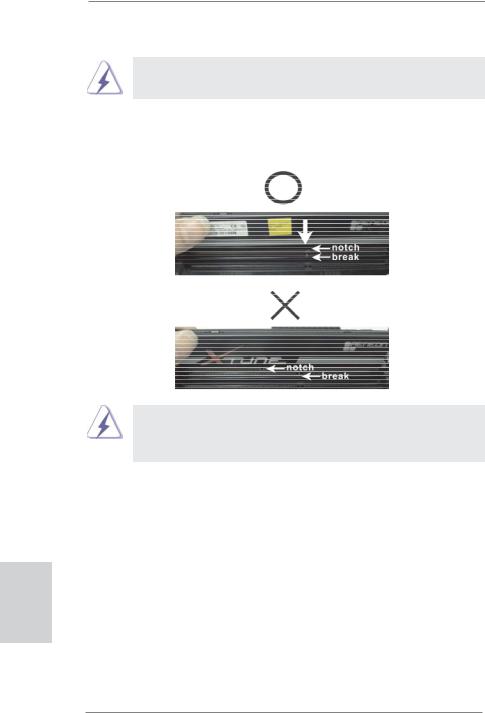
Installing a DIMM Please make sure to disconnect power supply before adding or removing DIMMs or the system components. Step 1. Unlock a DIMM slot by pressing the retaining clips outward. Step 2. Align a DIMM on the slot such that the notch on the DIMM matches the break on the slot.
-
Page 18: Expansion Slots (Pci And Pci Express Slots)
2.4 Expansion Slots (PCI and PCI Express Slots) There are 2 PCI slots and 3 PCI Express slots on this motherboard. PCI Slots: PCI slots are used to install expansion cards that have the 32-bit PCI interface. PCIE Slots: PCIE1 (PCIE x1 slot; Black) is used for PCI Express cards with x1 lane width cards, such as Gigabit LAN card and SATA2 card.
-
Page 19: Tm Tm
2.5 CrossFireX and Quad CrossFireX Operation Guide This motherboard supports CrossFireX and Quad CrossFireX feature. CrossFireX technology offers the most advantageous means available of combining multiple high performance Graphics Processing Units (GPU) in a single PC. Combining a range of different operating modes with intelligent software design and an innovative interconnect mechanism, CrossFireX enables the highest possible level of performance and image quality in any 3D application.
-
Page 20
Step 2. Connect two Radeon graphics cards by installing a CrossFire Bridge on the CrossFire Bridge Interconnects on the top of the Radeon graphics cards. (The CrossFire Bridge is provided with the graphics card you pur- chase, not bundled with this motherboard. Please refer to your graphics card vendor for details.) CrossFire Bridge Step 3. -
Page 21: Driver Installation And Setup
2.5.2 Driver Installation and Setup Step 1. Power on your computer and boot into OS. Step 2. Remove the AMD driver if you have any VGA driver installed in your sys- tem. The Catalyst Uninstaller is an optional download. We recommend using this utility to uninstall any previously installed Catalyst drivers prior to installation.
-
Page 22: Surround Display Information
Although you have selected the option “Enable CrossFire ”, the Cross- FireX function may not work actually. Your computer will automatically reboot. After restarting your computer, please confi rm whether the option “Enable CrossFire ” in “ATI Catalyst Control Center” is selected or not; if not, please select it again, and then you are able to enjoy the benefi…
-
Page 23: Asrock Smart Remote Installation Guide
2.7 ASRock Smart Remote Installation Guide ASRock Smart Remote is only used for ASRock motherboard with CIR header. Please refer to below procedures for the quick installation and usage of ASRock Smart Remote. Step1. Find the CIR header located next to the USB 2.0 header on ASRock…
-
Page 24
The Multi-Angle CIR Receiver does not support Hot-Plug function. Please install it before you boot the system. * ASRock Smart Remote is only supported by some of ASRock motherboards. Please refer to ASRock website for the motherboard support list: http://www.asrock.com… -
Page 25: Jumpers Setup
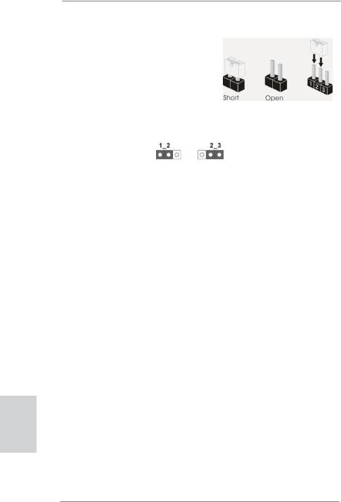
2.8 Jumpers Setup The illustration shows how jumpers are setup. When the jumper cap is placed on pins, the jumper is “Short”. If no jumper cap is placed on pins, the jumper is “Open”. The illustration shows a 3-pin jumper whose pin1 and pin2 are “Short”…
-
Page 26: Onboard Headers And Connectors
2.9 Onboard Headers and Connectors Onboard headers and connectors are NOT jumpers. Do NOT place jumper caps over these headers and connectors. Placing jumper caps over the headers and connectors will cause permanent damage of the motherboard! Serial ATA3 Connectors These six Serial ATA3 (SATA3) connectors support (SATA3_1: see p.12, No.
-
Page 27: Front Panel Audio Header
Infrared Module Header This header supports an IRTX +5VSB optional wireless transmitting (5-pin IR1) DUMMY and receiving infrared module. (see p.12 No. 27) IRRX Consumer Infrared Module Header This header can be used to connect the remote (4-pin CIR1) IRTX IRRX ATX+5VSB controller receiver.
-
Page 28
PWRBTN (Power Switch): Connect to the power switch on the chassis front panel. You may con- fi gure the way to turn off your system using the power switch. RESET (Reset Switch): Connect to the reset switch on the chassis front panel. Press the reset switch to restart the computer if the computer freezes and fails to per- form a normal restart. -
Page 29
CPU Fan Connectors Please connect the CPU fan FAN_SPEED_CONTROL CPU_FAN_SPEED cable to the connector and (4-pin CPU_FAN1) +12V match the black wire to the (see p.12 No. 5) ground pin. 1 2 3 4 Though this motherboard provides 4-Pin CPU fan (Quiet Fan) support, the 3-Pin CPU fan still can work successfully even without the fan speed control function. -
Page 30
Serial port Header This COM1 header supports a serial port module. (9-pin COM1) (see p.12 No.28) HDMI_SPDIF Header HDMI_SPDIF header, providing SPDIF audio output to HDMI (2-pin HDMI_SPDIF1) VGA card, allows the system to see p.12 No. 29) connect HDMI Digital TV/ projector/LCD devices. -
Page 31: Serial Ata3 (Sata3) Hard Disks Installation
2.10 Serial ATA3 (SATA3) Hard Disks Installation This motherboard adopts AMD SB950 chipset that supports Serial ATA3 (SATA3) hard disks and RAID (RAID 0, RAID 1, RAID 5 and RAID 10) functions. You may install SATA3 hard disks on this motherboard for internal storage devices. This sec- tion will guide you to install the SATA3 hard disks.
-
Page 32: Sata3 Hdd Hot Plug Feature And Operation Operation Guide
* The SATA3 Hot Plug feature might not be supported by the chipset because of its limitation, the SATA3 Hot Plug support information of our motherboard is indicated in the product spec on our website: www.asrock.com 2. Make sure your SATA3 HDD can support Hot Plug function from your dealer or HDD user manual.
-
Page 33: How To Hot Plug A Sata3 Hdd
How to Hot Plug a SATA3 HDD: Points of attention, before you process the Hot Plug: Please do follow below instruction sequence to process the Hot Plug, improper procedure will cause the SATA3 HDD damage and data loss. Please connect SATA power cable 1×4-pin Step 1 Connect SATA data cable to Step 2…
-
Page 34: Driver Installation Guide
STEP 2: Make a SATA3 Driver Diskette. (Please use USB fl oppy or fl oppy disk.) A. Insert the ASRock Support CD into your optical drive to boot your system. B. During POST at the beginning of system boot-up, press <F11> key, and then a window for boot devices selection appears.
-
Page 35: Installing Windows
STEP 3: Use “RAID Installation Guide” to set RAID confi guration. Before you start to confi gure RAID function, you need to check the RAID installation guide in the Support CD for proper confi guration. Please refer to the BIOS RAID installation guide part of the document in the following path in the Support CD: ..
-
Page 36: 64-Bit / Vista
® 2.15 Installing Windows 7 / 7 64-bit / Vista / Vista 64-bit / XP / XP 64-bit Without RAID Functions ® If you want to install Windows 7 / 7 64-bit / Vista / Vista 64-bit / XP / XP 64-bit OS on your SATA3 HDDs without RAID functions, please follow below procedures according to the OS you install.
-
Page 37: 64-Bit / Vista
® 2.15.2 Installing Windows 7 / 7 64-bit / Vista / Vista 64-bit Without RAID Functions ® If you want to install Windows 7 / 7 64-bit / Vista / Vista 64-bit on your SATA3 HDDs without RAID functions, please follow below steps. Using SATA3 HDDs with NCQ and Hot Plug functions (AHCI mode) STEP 1: Set up UEFI.
-
Page 38: Uefi Setup Utility
3. UEFI SETUP UTILITY 3.1 Introduction This section explains how to use the UEFI SETUP UTILITY to confi gure your sys- tem. The SPI Memory on the motherboard stores the UEFI SETUP UTILITY. You may run the UEFI SETUP UTILITY when you start up the computer. Please press <F2>…
-
Page 39: Navigation Keys
3.1.2 Navigation Keys Please check the following table for the function description of each navigation key. Navigation Key(s) Function Description Moves cursor left or right to select Screens Moves cursor up or down to select items + / — To change option for the selected items <Tab>…
-
Page 40: Main Screen
3.2 Main Screen When you enter the UEFI SETUP UTILITY, the Main screen will appear and display the system overview. System Browser System Browser can let you easily check your current system confi guration in UEFI setup. OMG (Online Management Guard) Administrators are able to establish an internet curfew or restrict internet access at specifi…
-
Page 41: Oc Tweaker Screen
ASRock UCC ASRock UCC (Unlock CPU Core) feature simplifi es AMD CPU activation. As long as a simple switch of the UEFI option “ASRock UCC”, you can unlock the extra CPU core to enjoy an instant performance boost. When UCC feature is enabled, the dual-core or triple-core CPU will boost to the…
-
Page 42
AMD Turbo Core Technology This item appears only when the processor you adopt supports this fea- ture. Use this to select enable or disable AMD Turbo Core Technology. Confi guration options: [Auto] and [Disabled]. The default value is [Auto]. AMD IO C-State Support This allows you to enable or disable AMD IO C-State Support. -
Page 43
DRAM Timing Control DRAM Slot Use this to select DRAM slot to view SPD data. The default value is [DDR3_A1]. DRAM Timing Control Use this to select DRAM control. The default value is [Auto]. Power Down Enable Use this item to enable or disable DDR power down mode. Bank Interleaving Interleaving allows memory accesses to be spread out over banks on the same node, or accross nodes, decreasing access contention. -
Page 44
Voltage Confi guration DRAM Voltage Use this to select DRAM Voltage. The default value is [Auto]. CPU Voltage Offset Use this to select CPU Voltage Offset. The default value is [Auto]. NB Voltage Use this to select NB Voltage. The default value is [Auto]. HT Voltage Use this to select HT Voltage. -
Page 45: Advanced Screen
3.4 Advanced Screen In this section, you may set the confi gurations for the following items: CPU Confi gu- ration, Nouth Bridge Confi guration, South Bridge Confi guration, Storage Confi gura- tion, Super IO Confi guration, ACPI Confi guration, and USB Confi guration. Setting wrong values in this section may cause the system to malfunction.
-
Page 46: Cpu Confi Guration
3.4.1 CPU Configuration Cool ‘n’ Quiet Use this item to enable or disable AMD’s Cool ‘n’ Quiet technology. The default value is [Enabled]. Confi guration options: [Enabled] and [Disabled]. ® If you install Windows 7 / Vista and want to enable this function, please set this item to [Enabled].
-
Page 47: North Bridge Confi Guration
3.4.2 North Bridge Configuration Primary Graphics Adapter This item will switch the PCI Bus scanning order while searching for video card. It allows you to select the type of Primary VGA in case of multiple video controllers. The default value of this feature is [PCI Express]. Con- fi…
-
Page 48: South Bridge Confi Guration
3.4.3 South Bridge Configuration Onboard HD Audio Select [Auto], [Enabled] or [Disabled] for the onboard HD Audio feature. If you select [Auto], the onboard HD Audio will be disabled when PCI Sound Card is plugged. Front Panel Select [Auto] or [Disabled] for the onboard HD Audio Front Panel. On/Off Play Use this item to enable or disable On/Off Play Technology.
-
Page 49: Storage Confi Guration
3.4.4 Storage Configuration SATA Controller Use this item to enable or disable the “SATA Controller” feature. SATA Mode Use this item to adjust SATA Mode. The default value of this option is [AHCI Mode]. Confi guration options: [AHCI Mode], [RAID Mode] and [IDE Mode]. If you set this item to RAID mode, it is suggested to install SATA ODD driver on SATA3_5 and SATA3_6 ports.
-
Page 50: Super Io Confi Guration
3.4.5 Super IO Configuration Serial Port Use this item to enable or disable the onboard serial port. Serial Port Address Use this item to set the address for the onboard serial port. Confi guration options: [3F8h / IRQ4] and [3E8h / IRQ4]. Infrared Port Use this item to enable or disable the onboard infrared port.
-
Page 51: Acpi Confi Guration
3.4.6 ACPI Configuration Suspend to RAM Use this item to select whether to auto-detect or disable the Suspend-to- RAM feature. Select [Auto] will enable this feature if the OS supports it. Check Ready Bit Use this item to enable or disable the feature Check Ready Bit. ACPI HPET table Use this item to enable or disable ACPI HPET Table.
-
Page 52: Usb Confi Guration
3.4.7 USB Configuration USB 2.0 Controller Use this item to enable or disable the use of USB 2.0 controller. USB 3.0 Controller Use this item to enable or disable the use of USB 3.0 controller. Legacy USB Support Use this option to select legacy support for USB devices. There are four confi…
-
Page 53: Hardware Health Event Monitoring Screen
3.5 Hardware Health Event Monitoring Screen In this section, it allows you to monitor the status of the hardware on your system, including the parameters of the CPU temperature, motherboard temperature, CPU fan speed, chassis fan speed, and the critical voltage. CPU Fan 1 &…
-
Page 54: Boot Screen
3.6 Boot Screen In this section, it will display the available devices on your system for you to confi g- ure the boot settings and the boot priority. Setup Prompt Timeout This shows the number of seconds to wait for setup activation key. 65535(0xFFFF) means indefi…
-
Page 55: Security Screen
3.7 Security Screen In this section, you may set or change the supervisor/user password for the system. For the user password, you may also clear it.
-
Page 56: Exit Screen
3.8 Exit Screen Save Changes and Exit When you select this option, it will pop-out the following message, “Save confi guration changes and exit setup?” Select [OK] to save the changes and exit the UEFI SETUP UTILITY. Discard Changes and Exit When you select this option, it will pop-out the following message, “Discard changes and exit setup?”…
-
Page 57: Software Support
Click on a specifi c item then follow the installation wizard to install it. 4.2.4 Contact Information If you need to contact ASRock or want to know more about ASRock, welcome to visit ASRock’s website at http://www.asrock.com; or you may contact your…
-
Page 58
Installing OS on a HDD Larger Than 2TB in AHCI Mode ® This motherboard is adopting UEFI BIOS that allows Windows OS to be installed on a large size HDD (>2TB). Please follow below procedure to install the operating system. ®… -
Page 59: Installing Os On A Hdd Larger Than 2Tb In Raid Mode
Installing OS on a HDD Larger Than 2TB in RAID Mode ® This motherboard is adopting UEFI BIOS that allows Windows OS to be installed on a large size HDD (>2TB). Please follow below procedure to install the operating system. ®…
-
Page 60
7. And then key in drvcfg –s [Drv number] [Ctrl number] to enter Raid Utility. For example: key in drvcfg –s 4E B5. 8. Choose Logical Drive Main Menu to set up Raid Drive. 9. Choose Logical Drive Create Menu to create a Raid Drive. 10. -
Page 61
11. Press Space on keyboard to toggle checkbox. 12. Choose Ld Size setting, and key in the Raid size. 13. After set up Raid size, please click Start to Create. 14. Press <F10> to exit Utility. 15. During reboot, please press <F11> to enter Boot Manual. Choose UEFI: SCSI CD/DVD Drive. -
Page 62
® 16. Follow Windows Installation Guide to install OS. ® If you install Windows 7 64-bit / Vista 64-bit in a large hard disk (ex. Disk ® volume > 2TB), it may take more time to boot into Windows or install driver/ utilities. -
Page 63
B. Disable “Volume Shadow Copy” service. a. Type “computer management” in the Start Menu, then press “Enter”. b. Go to “Services and Applications>Services”; Then double click “Volume Shadow Copy”. c. Set “Startup type” to “Disable” then Click “OK”. -
Page 64
C. Reboot your system. D. After reboot, please start to install motherboard drivers and utilities. ® Windows 7 64-bit: A. Please request the hotfi x KB2505454 thru this link: http://support.microsoft.com/kb/2505454/ ® B. After installing Windows 7 64-bit, install the hotfi x kb2505454. (This may take long time;…

1
ASRock 970 Pro3 Motherboard
English
Copyright Notice:
No part of this installation guide may be reproduced, transcribed, transmitted, or trans-
lated in any language, in any form or by any means, except duplication of documentation
by the purchaser for backup purpose, without written consent of ASRock Inc.
Products and corporate names appearing in this guide may or may not be registered
trademarks or copyrights of their respective companies, and are used only for identifi ca-
tion or explanation and to the owners’ benefi t, without intent to infringe.
Disclaimer:
Specifi cations and information contained in this guide are furnished for informational use
only and subject to change without notice, and should not be constructed as a commit-
ment by ASRock. ASRock assumes no responsibility for any errors or omissions that may
appear in this guide.
With respect to the contents of this guide, ASRock does not provide warranty of any kind,
either expressed or implied, including but not limited to the implied warranties or condi-
tions of merchantability or fi tness for a particular purpose. In no event shall ASRock, its
directors, offi cers, employees, or agents be liable for any indirect, special, incidental, or
consequential damages (including damages for loss of profi ts, loss of business, loss of
data, interruption of business and the like), even if ASRock has been advised of the pos-
sibility of such damages arising from any defect or error in the guide or product.
This device complies with Part 15 of the FCC Rules. Operation is subject to the following
two conditions:
(1) this device may not cause harmful interference, and
(2) this device must accept any interference received, including interference that
may cause undesired operation.
CALIFORNIA, USA ONLY
The Lithium battery adopted on this motherboard contains Perchlorate, a toxic substance
controlled in Perchlorate Best Management Practices (BMP) regulations passed by the
California Legislature. When you discard the Lithium battery in California, USA, please
follow the related regulations in advance.
“Perchlorate Material-special handling may apply, see
www.dtsc.ca.gov/hazardouswaste/perchlorate”
ASRock Website: http://www.asrock.com
Published April 2012
Copyright
©
2012 ASRock INC. All rights reserved.
-
Драйверы
36
-
Инструкции по эксплуатации
3

Asrock 970 Pro3 инструкция по эксплуатации
(64 страницы)
- Языки:Английский
-
Тип:
PDF -
Размер:
1.14 MB
Просмотр

Asrock 970 Pro3 инструкция по эксплуатации
(17 страниц)
- Языки:Английский
-
Тип:
PDF -
Размер:
1.28 MB
Просмотр

Asrock 970 Pro3 инструкция по эксплуатации
(182 страницы)
-
Тип:
PDF -
Размер:
2.19 MB
Просмотр
На NoDevice можно скачать инструкцию по эксплуатации для Asrock 970 Pro3. Руководство пользователя необходимо для ознакомления с правилами установки и эксплуатации Asrock 970 Pro3. Инструкции по использованию помогут правильно настроить Asrock 970 Pro3, исправить ошибки и выявить неполадки.
![]()
Copyright Notice:
No part of this installation guide may be reproduced, transcribed, transmitted, or translated in any language, in any form or by any means, except duplication of documentation by the purchaser for backup purpose, without written consent of ASRock Inc.
Products and corporate names appearing in this guide may or may not be registered trademarks or copyrights of their respective companies, and are used only for identification or explanation and to the owners’ benefit, without intent to infringe.
Disclaimer:
Specifications and information contained in this guide are furnished for informational use only and subject to change without notice, and should not be constructed as a commitment by ASRock. ASRock assumes no responsibility for any errors or omissions that may appear in this guide.
With respect to the contents of this guide, ASRock does not provide warranty of any kind, either expressed or implied, including but not limited to the implied warranties or conditions of merchantability or fitness for a particular purpose. In no event shall ASRock, its directors, officers, employees, or agents be liable for any indirect, special, incidental, or consequential damages (including damages for loss of profits, loss of business, loss of data, interruption of business and the like), even if ASRock has been advised of the possibility of such damages arising from any defect or error in the guide or product.
This device complies with Part 15 of the FCC Rules. Operation is subject to the following two conditions:
(1)this device may not cause harmful interference, and
(2)this device must accept any interference received, including interference that may cause undesired operation.
CALIFORNIA, USA ONLY
The Lithium battery adopted on this motherboard contains Perchlorate, a toxic substance controlled in Perchlorate Best Management Practices (BMP) regulations passed by the California Legislature. When you discard the Lithium battery in California, USA, please follow the related regulations in advance.
“Perchlorate Material-special handling may apply, see www.dtsc.ca.gov/hazardouswaste/perchlorate”
ASRock Website: http://www.asrock.com
Published April 2012
Copyright©2012 ASRock INC. All rights reserved.
1
English
ASRock 970 Pro3 Motherboard

English
Motherboard Layout
|
1 |
2 |
3 |
4 |
5 |
6 |
7 |
|||||||||||||
|
20.8cm (8.2-in) |
|||||||||||||||||||
|
Keyboard |
Mouse PS2 |
Support 8-Core CPU |
|||||||||||||||||
|
PS2 |
CPU_FAN2 |
CPU_FAN1 |
|||||||||||||||||
|
ATX12V1 |
|||||||||||||||||||
|
USB 2.0 |
|||||||||||||||||||
|
T: USB0 |
|||||||||||||||||||
|
B: USB1 |
|||||||||||||||||||
|
USB 2.0 |
AM3+DDR32100+ |
module) |
A2 (64 bit, 240-pin module) |
module) |
B2 (64 bit, 240-pin module) |
||||||||||||||
|
T: USB2 |
|||||||||||||||||||
|
B: USB3 |
|||||||||||||||||||
|
LAN |
|||||||||||||||||||
|
PHY |
|||||||||||||||||||
|
pin |
pin |
||||||||||||||||||
|
AM3bSOCKET |
FSB800 |
FSB800 |
30.5cm(12.0in)- |
||||||||||||||||
|
USB 2.0 |
RJ-45 LAN |
A1 (64 bit, 240- |
B1 (64 bit, 240- |
||||||||||||||||
|
T: USB4 |
|||||||||||||||||||
|
B: USB5 |
|||||||||||||||||||
|
USB 3.0 |
_ |
_ |
_ |
_ |
|||||||||||||||
|
T: USB0 |
DDR3 |
DDR3 |
DDR3 |
DDR3 |
|||||||||||||||
|
B: USB1 |
|||||||||||||||||||
|
140WCPU |
8 |
||||||||||||||||||
|
CTRBASS |
Bottom: |
REARSPK |
Center: |
SIDESPK |
Top: |
USB3.0 |
|||||||||||||
|
MICIN |
Bottom: |
FRONT |
Center: |
LINEIN |
Top: |
||||||||||||||
|
CHA_FAN1 |
AMD |
9 |
|||||||||||||||||
|
37 |
|||||||||||||||||||
|
PWR_FAN1 |
10 |
||||||||||||||||||
|
36 |
970 |
||||||||||||||||||
|
5 |
6 |
11 |
|||||||||||||||||
|
Chipset |
SATA3 |
SATA3 |
|||||||||||||||||
|
35 |
|||||||||||||||||||
|
PCIE1 |
|||||||||||||||||||
|
3 |
4 |
12 |
|||||||||||||||||
|
SATA3 |
SATA3 |
||||||||||||||||||
|
34 |
PCIE2 |
13 |
|||||||||||||||||
|
CMOS |
AMD |
||||||||||||||||||
|
BATTERY |
SB950 |
14 |
|||||||||||||||||
|
AUDIO |
|||||||||||||||||||
|
CODEC |
Chipset |
||||||||||||||||||
|
33 |
PCI1 |
||||||||||||||||||
|
32 |
ErP/EuP Ready |
X Fast LAN |
X Fast RAM |
X Fast USB |
|||||||||||||||
|
Super |
PCIE3 |
||||||||||||||||||
|
I/O |
970 Pro3 |
RoHS |
32Mb |
15 |
|||||||||||||||
|
BIOS |
|||||||||||||||||||
|
31 |
PCI2 |
SATA3_2 |
16 |
||||||||||||||||
|
CLRCMOS1 |
|||||||||||||||||||
|
1 |
17 |
||||||||||||||||||
|
COM1 |
USB_10_11 |
USB_8_9 |
USB_6_7 |
PANEL 1 |
SPEAKER1 |
||||||||||||||
|
HD_AUDIO1 |
IR1 |
CHA_FAN2 1 |
SATA3_1 |
||||||||||||||||
|
1 |
1 |
PLED1 |
18 |
||||||||||||||||
|
1 |
1 |
1 |
1 |
1 |
1 |
1 |
|||||||||||||
|
1 |
|
30 |
29 |
28 |
27 |
26 |
25 |
24 23 |
22 |
212019 |
|
|
1 |
ATX 12V Power Connector (ATX12V1) |
19 |
Power LED Header (PLED1) |
||||||
|
2 |
CPU Heatsink Retention Module |
20 |
Chassis Speaker Header (SPEAKER 1, Black) |
||||||
|
3 |
AM3+ CPU Socket |
21 |
Chassis Fan Connector (CHA_FAN2) |
||||||
|
4 |
CPU Fan Connector (CPU_FAN2) |
22 |
System Panel Header (PANEL1, Black) |
||||||
|
5 |
CPU Fan Connector (CPU_FAN1) |
23 |
USB 2.0 Header (USB_6_7, Black) |
||||||
|
6 |
2 x 240-pin DDR3 DIMM Slots |
24 |
Consumer Infrared Module Header (CIR1) |
||||||
|
(Dual Channel: DDR3_A1, DDR3_B1; Black) |
25 |
USB 2.0 Header (USB_8_9, Black) |
|||||||
|
7 |
2 x 240-pin DDR3 DIMM Slots |
26 |
USB 2.0 Header (USB_10_11, Black) |
||||||
|
(Dual Channel: DDR3_A2, DDR3_B2; Black) |
27 |
Infrared Module Header (IR1) |
|||||||
|
8 |
ATX Power Connector (ATXPWR1) |
28 |
COM Port Header (COM1) |
||||||
|
9 |
Power Fan Connector (PWR_FAN1) |
29 |
HDMI_SPDIF Header (HDMI_SPDIF1, Black) |
||||||
|
10 |
SATA3 Connector (SATA3_5, Gray) |
30 |
Front Panel Audio Header |
||||||
|
11 |
SATA3 Connector (SATA3_6, Gray) |
(HD_AUDIO1, Black) |
|||||||
|
12 |
SATA3 Connector (SATA3_4, Gray) |
31 |
PCI Slot (PCI2) |
||||||
|
13 |
SATA3 Connector (SATA3_3, Gray) |
32 |
PCI Express 2.0 x16 Slot (PCIE3; Black) |
||||||
|
14 |
Southbridge Controller |
33 |
PCI Slot (PCI1) |
||||||
|
15 |
SPI Flash Memory (32Mb) |
34 |
PCI Express 2.0 x16 Slot (PCIE2; Black) |
||||||
|
16 |
Clear CMOS Jumper (CLRCMOS1) |
35 |
PCI Express 2.0 x1 Slot (PCIE1; Black) |
||||||
|
17 |
SATA3 Connector (SATA3_2, Gray) |
36 |
Northbridge Controller |
||||||
|
18 |
SATA3 Connector (SATA3_1, Gray) |
37 |
Chassis Fan Connector (CHA_FAN1) |
2
ASRock 970 Pro3 Motherboard

I/O Panel
|
1 |
2 |
|||||||||||||||||||||
|
3 |
6 |
|||||||||||||||||||||
|
4 |
7 |
|||||||||||||||||||||
|
5 |
8 |
|||||||||||||||||||||
|
13 |
12 |
11 |
10 |
9 |
||
|
1 |
PS/2 Mouse Port (Green) |
8 |
Microphone (Pink) |
|||
|
* 2 |
LAN RJ-45 Port |
9 |
USB 3.0 |
Port (USB3_0_1) |
||
|
3 |
Side Speaker (Gray) |
10 |
USB 2.0 |
Port (USB_4_5) |
||
|
4 |
Rear Speaker (Black) |
11 |
USB 2.0 |
Port (USB_2_3) |
||
|
5 |
Central / Bass (Orange) |
12 |
USB 2.0 |
Port (USB_0_1) |
||
|
6 |
Line In (Light Blue) |
13 |
PS/2 Keyboard Port (Purple) |
**7 Front Speaker (Lime)
*There are two LED next to the LAN port. Please refer to the table below for the LAN port LED indications.
|
LAN Port LED Indications |
ACT/LINK SPEED |
||||||
|
Activity/Link LED |
SPEED LED |
||||||
|
LED |
LED |
||||||
|
Status |
Description |
Status |
Description |
||||
|
Off |
No Link |
Off |
10Mbps connection |
||||
|
Blinking |
Data Activity |
Orange |
100Mbps connection |
||||
|
On |
Link |
Green |
1Gbps connection |
LAN Port |
|||
**If you use 2-channel speaker, please connect the speaker’s plug into “Front Speaker Jack”. See the table below for connection details in accordance with the type of speaker you use.
TABLE for Audio Output Connection
|
Audio Output Channels |
Front Speaker |
Rear Speaker |
Central / Bass |
Side Speaker |
|
(No. 7) |
(No. 4) |
(No. 5) |
(No. 3) |
|
|
2 |
V |
— |
— |
— |
|
4 |
V |
V |
— |
— |
|
6 |
V |
V |
V |
— |
|
8 |
V |
V |
V |
V |
To enable Multi-Streaming function, you need to connect a front panel audio cable to the front panel audio header. After restarting your computer, you will find “Mixer” tool on your system. Please select “Mixer ToolBox”  , click “Enable playback multi-streaming”, and click “ok”.
Choose “2CH”, “4CH”, “6CH”, or “8CH” and then you are allowed to select “Realtek HDA Primary output” to use Rear Speaker, Central/Bass, and Front Speaker, or select “Realtek HDA Audio 2nd output” to use front panel audio.
3
English
ASRock 970 Pro3 Motherboard

1. Introduction
Thank you for purchasing ASRock 970 Pro3 motherboard, a reliable motherboard produced under ASRock’s consistently stringent quality control. It delivers excellent performance with robust design conforming to ASRock’s commitment to quality and endurance.
This Quick Installation Guide contains introduction of the motherboard and step-by- step installation guide. More detailed information of the motherboard can be found in the user manual presented in the Support CD.
Because the motherboard specifications and the BIOS software might be updated, the content of this manual will be subject to change without notice. In case any modifications of this manual occur, the updated version will be available on ASRock website without further notice. You may find the latest VGA cards and CPU support lists on ASRock website as well. ASRock website http://www.asrock.com
If you require technical support related to this motherboard, please visit our website for specific information about the model you are using. www.asrock.com/support/index.asp
1.1 Package Contents
ASRock 970 Pro3 Motherboard
(ATX Form Factor: 12.0-in x 8.2-in, 30.5 cm x 20.8 cm) ASRock 970 Pro3 Quick Installation Guide
ASRock 970 Pro3 Support CD
2 x Serial ATA (SATA) Data Cables (Optional)
1 x I/O Panel Shield
ASRock Reminds You…
To get better performance in Windows® 7 / 7 64-bit / VistaTM / VistaTM 64 bit, it is recommended to set the BIOS option in Storage Configuration to AHCI mode. For the BIOS setup, please refer to the “User Manual” in our support CD for details.
English
4
ASRock 970 Pro3 Motherboard

1.2 Specifications
|
Platform |
— ATX Form Factor: 12.0-in x 8.2-in, 30.5 cm x 20.8 cm |
|
— All Solid Capacitor design |
|
|
CPU |
— Support for Socket AM3+ processors |
|
— Support for Socket AM3 processors: AMD PhenomTM II X6 / |
|
|
X4 / X3 / X2 (except 920 / 940) / Athlon II X4 / X3 / X2 / |
|
|
Sempron processors |
|
|
— Supports 8-Core CPU |
|
|
— Supports UCC feature (Unlock CPU Core) (see CAUTION 1) |
|
|
— 4 + 1 Power Phase Design |
|
|
— Supports CPU up to 140W |
|
|
— Supports AMD’s Cool ‘n’ QuietTM Technology |
|
|
— FSB 2400 MHz (4.8 GT/s) |
|
|
— Supports Untied Overclocking Technology (see CAUTION 2) |
|
|
— Supports Hyper-Transport 3.0 (HT 3.0) Technology |
|
|
Chipset |
— Northbridge: AMD 970 |
|
— Southbridge: AMD SB950 |
|
|
Memory |
— Dual Channel DDR3 Memory Technology (see CAUTION 3) |
|
— 4 x DDR3 DIMM slots |
|
|
— Support DDR3 2100(OC)/1866(OC)/1800(OC)/1600(OC)/ |
|
|
1333/1066/800 non-ECC, un-buffered memory |
|
|
(see CAUTION 4) |
|
|
— Max. capacity of system memory: 32GB (see CAUTION 5) |
|
|
Expansion Slot |
— 2 x PCI Express 2.0 x16 slots |
|
(PCIE2 @ x16 mode; PCIE3 @ x4 mode) |
|
|
— 1 x PCI Express 2.0 x1 slot |
|
|
— 2 x PCI slots |
|
|
— Supports AMD Quad CrossFireXTM and CrossFireXTM |
|
|
Audio |
— 7.1 CH HD Audio with Content Protection |
|
(Realtek ALC892 Audio Codec) |
|
|
— Premium Blu-ray audio support |
|
|
— Supports THX TruStudioTM |
|
|
LAN |
— PCIE x1 Gigabit LAN 10/100/1000 Mb/s |
|
— Realtek RTL8111E |
|
|
— Supports Wake-On-LAN |
|
|
— Supports LAN Cable Detection |
|
|
— Supports Energy Efficient Ethernet 802.3az |
|
|
— Supports PXE |
ASRock 970 Pro3 Motherboard

|
Rear Panel I/O |
I/O Panel |
|
— 1 x PS/2 Mouse Port |
|
|
— 1 x PS/2 Keyboard Port |
|
|
— 6 x Ready-to-Use USB 2.0 Ports |
|
|
— 2 x Ready-to-Use USB 3.0 Ports |
|
|
— 1 x RJ-45 LAN Port with LED (ACT/LINK LED and SPEED |
|
|
LED) |
|
|
— HD Audio Jack: Side Speaker/Rear Speaker/Central/Bass/ |
|
|
Line in/Front Speaker/Microphone (see CAUTION 6) |
|
|
SATA3 |
— 6 x SATA3 6.0 Gb/s connectors, support RAID (RAID 0, |
|
RAID 1, RAID 5 and RAID 10), NCQ, AHCI and «Hot Plug» |
|
|
functions |
|
|
USB 3.0 |
— 2 x USB 3.0 ports by Etron EJ168A, support USB 1.0/2.0/3.0 |
|
up to 5Gb/s |
|
|
Connector |
— 6 x SATA3 6.0Gb/s connectors |
|
— 1 x IR header |
|
|
— 1 x CIR header |
|
|
— 1 x COM port header |
|
|
— 1 x HDMI_SPDIF header |
|
|
— 1 x Power LED header |
|
|
— 2 x CPU Fan connectors (1 x 4-pin, 1 x 3-pin) |
|
|
— 2 x Chassis Fan connectors (1 x 4-pin, 1 x 3-pin) |
|
|
— 1 x Power Fan connector (3-pin) |
|
|
— 24 pin ATX power connector |
|
|
— 8 pin 12V power connector |
|
|
— Front panel audio connector |
|
|
— 3 x USB 2.0 headers (support 6 USB 2.0 ports) |
|
|
BIOS Feature |
— 32Mb AMI UEFI Legal BIOS with GUI support |
|
— Supports “Plug and Play” |
|
|
— ACPI 1.1 Compliance Wake Up Events |
|
|
— Supports jumperfree |
|
|
— SMBIOS 2.3.1 Support |
|
|
— CPU, VCCM, NB, SB Voltage Multi-adjustment |
|
|
Support CD |
— Drivers, Utilities, AntiVirus Software (Trial Version), |
|
CyberLink MediaEspresso 6.5 Trial, AMD OverDriveTM Utility, |
|
|
AMD Fusion, AMD Fusion Media Explorer, ASRock MAGIX |
|
|
Multimedia Suite — OEM |
|
ASRock 970 Pro3 Motherboard

|
Unique Feature |
— ASRock Extreme Tuning Utility (AXTU) (see CAUTION 7) |
|
|
— ASRock Instant Boot |
||
|
— ASRock Instant Flash (see CAUTION 8) |
||
|
— ASRock APP Charger (see CAUTION 9) |
||
|
— ASRock SmartView (see CAUTION 10) |
||
|
— ASRock XFast USB (see CAUTION 11) |
||
|
— ASRock XFast LAN (see CAUTION 12) |
||
|
— ASRock XFast RAM (see CAUTION 13) |
||
|
— ASRock Crashless BIOS (see CAUTION 14) |
||
|
— ASRock OMG (Online Management Guard) |
||
|
(see CAUTION 15) |
||
|
— ASRock Internet Flash (see CAUTION 16) |
||
|
— ASRock On/Off Play Technology (see CAUTION 17) |
||
|
— Hybrid Booster: |
||
|
— CPU Frequency Stepless Control (see CAUTION 18) |
||
|
— ASRock U-COP (see CAUTION 19) |
||
|
— Boot Failure Guard (B.F.G.) |
||
|
— Turbo UCC |
||
|
Hardware |
— CPU Temperature Sensing |
|
|
Monitor |
— Chassis Temperature Sensing |
|
|
— CPU/Chassis/Power Fan Tachometer |
||
|
— CPU/Chassis Quiet Fan |
||
|
— CPU/Chassis Fan Multi-Speed Control |
||
|
— Voltage Monitoring: +12V, +5V, +3.3V, Vcore |
||
|
OS |
— Microsoft® Windows® 7 / 7 64-bit / VistaTM / VistaTM 64-bit / XP |
|
|
/ XP 64-bit compliant (see CAUTION 20) |
||
|
Certifications |
— FCC, CE, WHQL |
—ErP/EuP Ready (ErP/EuP ready power supply is required) (see CAUTION 21)
*For detailed product information, please visit our website: http://www.asrock.com
WARNING
Please realize that there is a certain risk involved with overclocking, including adjusting the setting in the BIOS, applying Untied Overclocking Technology, or using the third-party overclocking tools. Overclocking may affect your system stability, or even cause damage to the components and devices of your system. It should be done at your own risk and expense.
We are not responsible for possible damage caused by overclocking.
ASRock 970 Pro3 Motherboard

CAUTION!
1.ASRock UCC (Unlock CPU Core) feature simplifies AMD CPU activation. As long as a simple switch of the UEFI option “ASRock UCC”, you can unlock the extra CPU core to enjoy an instant performance boost. When UCC feature is enabled, the dual-core or triple-core CPU will boost to the quad-core CPU, and some CPU, including quad-core CPU, can also increase L3 cache size up to 6MB, which means you can enjoy the upgrade CPU performance with a better price. Please be noted that UCC feature is supported with AM3/AM3+ CPU only, and in addition, not every AM3/AM3+ CPU can support this function because some CPU’s hidden core may be malfunctioned.
2.This motherboard supports Untied Overclocking Technology. Please read “Untied Overclocking Technology” on page 29 for details.
3.This motherboard supports Dual Channel Memory Technology. Before you implement Dual Channel Memory Technology, make sure to read the installation guide of memory modules on page 13 for proper installation.
4.Whether 2100/1866/1800/1600MHz memory speed is supported depends on the AM3/AM3+ CPU you adopt. If you want to adopt DDR3 2100/1866/1800/1600 memory module on this motherboard, please refer to the memory support list on our website for the compatible memory modules. Non OC mode’s DDR3 1866 is supported by AM3+ CPU.
ASRock website: http://www.asrock.com
5.Due to the operating system limitation, the actual memory size may be less than 4GB for the reservation for system usage under Windows® 7 / VistaTM / XP. For Windows® 64-bit OS with 64-bit CPU, there is no such limitation. You can use ASRock XFast RAM to utilize the memory that Windows® cannot use.
6.For microphone input, this motherboard supports both stereo and mono modes. For audio output, this motherboard supports 2-channel, 4-chan- nel, 6-channel, and 8-channel modes. Please check the table on page 3 for proper connection.
7.ASRock Extreme Tuning Utility (AXTU) is an all-in-one tool to ne-tune different system functions in a user-friendly interface, which is including Hardware Monitor, Fan Control, Overclocking, OC DNA and IES. In Hardware Monitor, it shows the major readings of your system. In Fan Control, it shows the fan speed and temperature for you to adjust. In Overclocking, you are allowed to overclock CPU frequency for optimal system performance. In OC DNA, you can save your OC settings as a profile and share with your friends. Your friends then can load the OC profile to their own system to get the same OC settings. In IES (Intelligent Energy Saver), the voltage regulator can reduce the number of output phases to improve efficiency when the CPU cores are idle without sacrificing computing performance. Please visit our website for the operation procedures of ASRock Extreme Tuning Utility (AXTU).
ASRock website: http://www.asrock.com
ASRock 970 Pro3 Motherboard

8.ASRock Instant Flash is a BIOS flash utility embedded in Flash ROM. This convenient BIOS update tool allows you to update system BIOS without entering operating systems first like MS-DOS or Windows®. With this utility, you can press <F6> key during the POST or press <F2> key to BIOS setup menu to access ASRock Instant Flash. Just launch this tool and save the new BIOS file to your USB flash drive, floppy disk or hard drive, then you can update your BIOS only in a few clicks without preparing an additional floppy diskette or other complicated flash utility. Please be noted that the USB flash drive or hard drive must use FAT32/16/12 file system.
9.If you desire a faster, less restricted way of charging your Apple devices, such as iPhone/iPod/iPad Touch, ASRock has prepared a wonderful solution for you — ASRock APP Charger. Simply installing the APP Charger driver, it makes your iPhone charged much quickly from your computer and up to 40% faster than before. ASRock APP Charger allows you to quickly charge many Apple devices simultaneously and even supports continuous charging when your PC enters into Standby mode (S1), Suspend to RAM (S3), hibernation mode (S4) or power off (S5). With APP Charger driver installed, you can easily enjoy the marvelous charging experience than ever.
ASRock website: http://www.asrock.com/Feature/AppCharger/index.asp
10.ASRock SmartView, a new function of internet browser, is the smart start page for IE that combines your most visited web sites, your history, your Facebook friends and your real-time newsfeed into an enhanced view for a more personal Internet experience. ASRock motherboards are exclusively equipped with the ASRock SmartView utility that helps you keep in touch with friends on-the-go. To use ASRock SmartView feature, please make sure your OS version is Windows® 7 / 7 64 bit / VistaTM / VistaTM 64 bit, and your browser version is IE8.
ASRock website: http://www.asrock.com/Feature/SmartView/index.asp
11.ASRock XFast USB can boost USB storage device performance. The performance may depend on the property of the device.
12.ASRock XFast LAN provides a faster internet access, which includes below benefits. LAN Application Prioritization: You can configure your application priority ideally and/or add new programs. Lower Latency in Game: After setting online game priority higher, it can lower the latency in game. Traffic Shaping: You can watch Youtube HD video and download files simultaneously. Real-Time Analysis of Your Data: With the status window, you can easily recognize which data streams you are currently transferring.
13.ASRock XFast RAM is a new function that is included into ASRock Extreme Tuning Utility (AXTU). It fully utilizes the memory space that cannot be used under Windows® OS 32-bit CPU. ASRock XFast RAM shortens the loading time of previously visited websites, making web surfing faster than ever. And it also boosts the speed of Adobe Photoshop 5 times faster. Another advantage of ASRock XFast RAM is that it reduces the
ASRock 970 Pro3 Motherboard

frequency of accessing your SSDs or HDDs in order to extend their lifespan.
14.ASRock Crashless BIOS allows users to update their BIOS without fear of failing. If power loss occurs during the BIOS update process, ASRock Crashless BIOS will automatically finish the BIOS update procedure after regaining power. Please note that BIOS files need to be placed in the root directory of your USB disk. Only USB2.0 ports support this feature.
15.Administrators are able to establish an internet curfew or restrict internet access at specified times via OMG. You may schedule the starting and ending hours of internet access granted to other users. In order to prevent users from bypassing OMG, guest accounts without permission to modify the system time are required.
16.ASRock Internet Flash searches for available UEFI firmware updates from our servers. In other words, the system can auto-detect the latest UEFI from our servers and flash them without entering Windows® OS. Please note that you must be running on a DHCP configured computer in order to enable this function.
17.ASRock On/Off Play Technology allows users to enjoy the great audio experience from the portable audio devices, such like MP3 player or mobile phone to your PC, even when the PC is turned off (or in ACPI S5 mode)! This motherboard also provides a free 3.5mm audio cable (optional) that ensures users the most convenient computing environment.
18.Although this motherboard offers stepless control, it is not recommended to perform over-clocking. Frequencies other than the recommended CPU bus frequencies may cause the instability of the system or damage the CPU.
19.While CPU overheat is detected, the system will automatically shutdown. Before you resume the system, please check if the CPU fan on the motherboard functions properly and unplug the power cord, then plug it back again. To improve heat dissipation, remember to spray thermal grease between the CPU and the heatsink when you install the PC system.
20.ASRock XFast RAM is not supported by Microsoft® Windows® XP / XP 64-bit.
21.EuP, stands for Energy Using Product, was a provision regulated by European Union to define the power consumption for the completed system. According to EuP, the total AC power of the completed system shall be under 1.00W in off mode condition. To meet EuP standard, an EuP ready motherboard and an EuP ready power supply are required. According to Intel’s suggestion, the EuP ready power supply must meet the standard of 5v standby power efficiency is higher than 50% under 100 mA current consumption. For EuP ready power supply selection, we recommend you checking with the power supply manufacturer for more details.
ASRock 970 Pro3 Motherboard
![]()
2. Installation
This is an ATX form factor (12.0-in x 8.2-in, 30.5 cm x 20.8 cm) motherboard. Before you install the motherboard, study the configuration of your chassis to ensure that the motherboard fits into it.
Pre-installation Precautions
Take note of the following precautions before you install motherboard components or change any motherboard settings.
Before you install or remove any component, ensure that the power is switched off or the power cord is detached from the power supply. Failure to do so may cause severe damage to the motherboard, peripherals, and/or components.
1.Unplug the power cord from the wall socket before touching any component.
2.To avoid damaging the motherboard components due to static electricity, NEVER place your motherboard directly on the carpet or the like. Also remember to use a grounded wrist strap or touch a safety grounded object before you handle components.
3.Hold components by the edges and do not touch the ICs.
4.Whenever you uninstall any component, place it on a grounded antistatic pad or in the bag that comes with the component.
5.When placing screws into the screw holes to secure the motherboard to the chassis, please do not over-tighten the screws! Doing so may damage the motherboard.
English
11
ASRock 970 Pro3 Motherboard

2.1 CPU Installation
Step 1. Unlock the socket by lifting the lever up to a 90o angle.
Step 2. Position the CPU directly above the socket such that the CPU corner with the golden triangle matches the socket corner with a small triangle.
Step 3. Carefully insert the CPU into the socket until it fits in place.
The CPU fits only in one correct orientation. DO NOT force the CPU into the socket to avoid bending of the pins.
Step 4. When the CPU is in place, press it firmly on the socket while you push down the socket lever to secure the CPU. The lever clicks on the side tab to indicate that it is locked.
|
Lever 90° Up |
||
|
CPU Golden Triangle |
||
|
Socker Corner |
||
|
Small Triangle |
||
|
STEP 1: |
STEP 2 / STEP 3: |
STEP 4: |
|
Lift Up The Socket Lever |
Match The CPU Golden Triangle |
Push Down And Lock |
|
To The Socket Corner Small |
The Socket Lever |
|
|
Triangle |
2.2 Installation of CPU Fan and Heatsink
After you install the CPU into this motherboard, it is necessary to install a larger heatsink and cooling fan to dissipate heat. You also need to spray thermal grease between the CPU and the heatsink to improve heat dissipation. Make sure that the CPU and the heatsink are securely fastened and in good contact with each other. Then connect the CPU fan to the CPU FAN connector (CPU_FAN1, see Page 2, No. 5 or CPU_FAN2, see Page 2, No. 4). For proper installation, please kindly refer to the instruction manuals of the CPU fan and the heatsink.
English
12
ASRock 970 Pro3 Motherboard

2.3 Installation of Memory Modules (DIMM)
This motherboard provides four 240-pin DDR3 (Double Data Rate 3) DIMM slots, and supports Dual Channel Memory Technology. For dual channel configuration, you always need to install identical (the same brand, speed, size and chip-type) DDR3 DIMM pair in the slots. In other words, you have to install identical DDR3 DIMM pair in Dual Channel (DDR3_A1 and DDR3_B1; Black slots; see p.2 No.6) or identical DDR3 DIMM pair in Dual Channel (DDR3_A2 and DDR3_B2; Black slots; see p.2 No.7), so that Dual Channel Memory Technology can be activated. This motherboard also allows you to install four DDR3 DIMMs for dual channel configuration, and please install identical DDR3 DIMMs in all four slots. You may refer to the Dual Channel Memory Configuration Table below.
|
Dual Channel Memory Configurations |
||||||||||
|
DDR3_A1 |
DDR3_A2 |
DDR3_B1 |
DDR3_B2 |
|||||||
|
(Black Slot) |
(Black Slot) |
(Black Slot) |
(Black Slot) |
|||||||
|
(1) |
Populated |
— |
Populated |
— |
||||||
|
(2) |
— |
Populated |
— |
Populated |
||||||
|
(3)* |
Populated |
Populated |
Populated |
Populated |
||||||
|
* |
all four |
|||||||||
|
For the configuration (3), please install identical DDR3 DIMMs in |
||||||||||
|
slots. |
||||||||||
|
1. |
Please install the memory module into the slots DDR3_A2 and |
|||||||||
|
DDR3_B2 for the first priority. |
||||||||||
|
2. |
If you want to install two memory modules, for optimal compatibility |
|||||||||
|
and reliability, it is recommended to install them either in the set of |
||||||||||
|
slots DDR3_A1 and DDR3_B1, or in the set of slots DDR3_A2 and |
||||||||||
|
DDR3_B2. |
||||||||||
|
3. |
If only one memory module or three memory modules are installed |
|||||||||
|
in the DDR3 DIMM slots on this motherboard, it is unable to activate |
||||||||||
|
the Dual Channel Memory Technology. |
||||||||||
|
4. |
If a pair of memory modules is NOT installed in the same Dual |
|||||||||
|
Channel, for example, installing a pair of memory modules in |
||||||||||
|
DDR3_A1 and DDR3_A2, it is unable to activate the Dual Channel |
||||||||||
|
Memory Technology . |
English |
|||||||||
|
5. |
It is not allowed to install a DDR or DDR2 memory module into |
|||||||||
|
DDR3 slot; otherwise, this motherboard and DIMM may be dam- |
||||||||||
|
aged. |
||||||||||
|
6. |
If you adopt DDR3 2100/1866/1800/1600 memory modules on this |
|||||||||
|
motherboard, it is recommended to install them on DDR3_A2 and |
||||||||||
|
DDR3_B2 slots. |
||||||||||
13
ASRock 970 Pro3 Motherboard
Installing a DIMM
Please make sure to disconnect power supply before adding or removing DIMMs or the system components.
Step 1. Unlock a DIMM slot by pressing the retaining clips outward.
Step 2. Align a DIMM on the slot such that the notch on the DIMM matches the break on the slot.
The DIMM only fits in one correct orientation. It will cause permanent damage to the motherboard and the DIMM if you force the DIMM into the slot at incorrect orientation.
Step 3. Firmly insert the DIMM into the slot until the retaining clips at both ends fully snap back in place and the DIMM is properly seated.
English
14
ASRock 970 Pro3 Motherboard
2.4 Expansion Slots (PCI and PCI Express Slots)
There are 2 PCI slots and 3 PCI Express slots on this motherboard.
PCI Slots: PCI slots are used to install expansion cards that have the 32-bit PCI interface.
PCIE Slots:
PCIE1 (PCIE x1 slot; Black) is used for PCI Express cards with x1 lane width cards, such as Gigabit LAN card and SATA2 card.
PCIE2 (PCIE x16 slot; Black) is used for PCI Express x16 lane width graphics cards, or used to install PCI Express graphics cards to support CrossFireXTM function.
PCIE3 (PCIE x16 slot; Black) is used for PCI Express x4 lane width cards, or used to install PCI Express graphics cards to support CrossFireXTM function.
1.In single VGA card mode, it is recommended to install a PCI Express x16 graphics card on PCIE2 slot.
2.In CrossFireXTM mode, please install PCI Express x16 graphics cards on PCIE2 and PCIE3 slots. Therefore, PCIE2 slot will work at x16 bandwidth while PCIE3 slot will work at x4 bandwidth.
3.Please connect a chassis fan to motherboard chassis fan connector (CHA_FAN1 or CHA_FAN2) when using multiple graphics cards for better thermal environment.
Installing an expansion card
Step 1. Before installing the expansion card, please make sure that the power supply is switched off or the power cord is unplugged. Please read the documentation of the expansion card and make necessary hardware settings for the card before you start the installation.
Step 2. Remove the system unit cover (if your motherboard is already installed in a chassis).
Step 3. Remove the bracket facing the slot that you intend to use. Keep the screws for later use.
Step 4. Align the card connector with the slot and press firmly until the card is completely seated on the slot.
Step 5. Fasten the card to the chassis with screws. Step 6. Replace the system cover.
15
English
ASRock 970 Pro3 Motherboard

2.5 CrossFireXTM and Quad CrossFireXTM Operation Guide
This motherboard supports CrossFireXTM and Quad CrossFireXTM feature. CrossFireXTM technology offers the most advantageous means available of combining multiple high performance Graphics Processing Units (GPU) in a single PC. Combining a range of different operating modes with intelligent software design and an innovative interconnect mechanism, CrossFireXTM enables the highest possible level of performance and image quality in any 3D application. Currently CrossFireXTM feature is supported with Windows® XP with Service Pack 2 / VistaTM / 7 OS. Quad CrossFireXTM feature are supported with Windows® VistaTM / 7 OS only. Please check AMD website for AMD CrossFireXTM driver updates.
1.If a customer incorrectly configures their system they will not see the performance benefits of CrossFireXTM. All three CrossFireXTM components, a CrossFireXTM Ready graphics card, a CrossFireXTM Ready motherboard and a CrossFireXTM Edition co-processor graphics card, must be installed correctly to benefit from the CrossFireXTM multi-GPU platform.
2.If you pair a 12-pipe CrossFireXTM Edition card with a 16-pipe card, both cards will operate as 12-pipe cards while in CrossFireXTM mode.
2.5.1Graphics Card Setup
2.5.1.1Installing Two CrossFireXTM-Ready Graphics Cards
Different CrossFireXTM cards may require different methods to enable CrossFireXTM feature. For other CrossFireXTM cards that AMD has released or will release in the future, please refer to AMD graphics card manuals for detailed installation guide.
Step 1. Insert one Radeon graphics card into PCIE2 slot and the other Radeon graphics card to PCIE3 slot. Make sure that the cards are properly seated on the slots.
English
16
ASRock 970 Pro3 Motherboard

Step 2. Connect two Radeon graphics cards by installing a CrossFire Bridge on the CrossFire Bridge Interconnects on the top of the Radeon graphics cards. (The CrossFire Bridge is provided with the graphics card you purchase, not bundled with this motherboard. Please refer to your graphics card vendor for details.)
CrossFire Bridge
or
Step 3. Connect the DVI monitor cable to the DVI connector on the Radeon graphics card on PCIE2 slot. (You may use the DVI to D-Sub adapter to convert the DVI connector to D-Sub interface, and then connect the D-Sub monitor cable to the DVI to D-Sub adapter.)
English
17
ASRock 970 Pro3 Motherboard

2.5.2 Driver Installation and Setup
Step 1. Power on your computer and boot into OS.
Step 2. Remove the AMD driver if you have any VGA driver installed in your system.
The Catalyst Uninstaller is an optional download. We recommend using this utility to uninstall any previously installed Catalyst drivers prior to installation. Please check AMD website for AMD driver updates.
Step 3. Install the required drivers to your system.
For Windows® XP OS:
A.AMD recommends Windows® XP Service Pack 2 or higher to be installed (If you have Windows® XP Service Pack 2 or higher installed in your system, there is no need to download it again): http://www.microsoft.com/windowsxp/sp2/default.mspx
B.You must have Microsoft .NET Framework installed prior to downloading and installing the CATALYST Control Center. Please check Microsoft website for details.
For Windows® 7 / VistaTM OS:
Install the CATALYST Control Center. Please check AMD website for details.
Step 4. Restart your computer.
Step 5. Install the VGA card drivers to your system, and restart your computer. Then you will find “ATI Catalyst Control Center” on your Windows® taskbar.
ATI Catalyst Control Center
Step 6. Double-click “ATI Catalyst Control Center”. Click “View”, select “CrossFireXTM”, and then check the item “Enable CrossFireXTM”. Select “2 GPUs” and click “Apply” (if you install two Radeon graphics cards).
English
18
ASRock 970 Pro3 Motherboard

Although you have selected the option “Enable CrossFireTM”, the CrossFireXTM function may not work actually. Your computer will automatically reboot. After restarting your computer, please confirm whether the option “Enable CrossFireTM” in “ATI Catalyst Control Center” is selected or not; if not, please select it again, and then you are able to enjoy the benefit of CrossFireXTM feature.
Step 7. You can freely enjoy the benefit of CrossFireXTM or Quad CrossFireXTM feature.
*CrossFireXTM appearing here is a registered trademark of AMD Technologies Inc., and is used only for identification or explanation and to the owners’ benefit, without intent to infringe.
*For further information of AMD CrossFireXTM technology, please check AMD website for updates and details.
2.6 Surround Display Feature
This motherboard supports Surround Display upgrade. With the external add-on PCI Express VGA cards, you can easily enjoy the benefits of Surround Display feature. For the detailed instruction, please refer to the document at the following path in the Support CD:
.. Surround Display Information
English
19
ASRock 970 Pro3 Motherboard

English
2.7 ASRock Smart Remote Installation Guide
ASRock Smart Remote is only used for ASRock motherboard with CIR header. Please refer to below procedures for the quick installation and usage of ASRock Smart Remote.
Step1. Find the CIR header located next to the USB 2.0 header on ASRock motherboard.
Step2. Connect the front USB cable to the USB 2.0 header (as below, pin 1-5) and the CIR header. Please make sure the wire assignments and the pin assignments are matched correctly.
 USB 2.0 header (9-pin, black)
 CIR header (4-pin, gray)
USB_PWR
P-
P+
GND DUMMY
1 2 3 4 5
GND
IRTX
IRRX
ATX+5VSB
|
Step3. |
Install Multi-Angle CIR Receiver to the front USB port. |
|
Step4. |
Boot up your system. Press <F2> or <Del> to enter BIOS Setup Utility. |
|
Make sure the option «CIR Controller» is setting at [Enabled]. |
|
|
(Advanced -> Super IO Configuration -> CIR Controller -> [Enabled]) |
|
|
If you cannot find this option, please shut down your system and install |
|
|
Multi-Angle CIR Receiver to the other front USB port then try again. |
|
|
Step5. |
Enter Windows. Execute ASRock support CD and install CIR Driver. (It is |
|
listed at the bottom of driver list.) |
20
ASRock 970 Pro3 Motherboard
![]()
3 CIR sensors in different angles
1.Only one of the front USB port can support CIR function. When the CIR function is enabled, the other port will remain USB function.
2.Multi-Angle CIR Receiver is used for front USB only. Please do not use the rear USB bracket to connect it on the rear panel. Multi-Angle CIR Receiver can receive the multi-direction infrared signals (top, down and front), which is compatible with most of the chassis on the market.
3.The Multi-Angle CIR Receiver does not support Hot-Plug function. Please install it before you boot the system.
*ASRock Smart Remote is only supported by some of ASRock motherboards. Please refer to ASRock website for the motherboard support list: http://www.asrock.com
English
21
ASRock 970 Pro3 Motherboard
2.8 Jumpers Setup
The illustration shows how jumpers are setup. When the jumper cap is placed on pins, the jumper is “Short”. If no jumper cap is placed on pins, the jumper is “Open”. The illustration shows a 3-pin jumper whose pin1 and pin2 are “Short” when jumper cap is placed on these 2 pins.
|
Jumper |
Setting |
Description |
|
Clear CMOS Jumper |
||
|
(CLRCMOS1) |
||
|
(see p.2, No. 16) |
Default |
Clear CMOS |
Note: CLRCMOS1 allows you to clear the data in CMOS. To clear and reset the system parameters to default setup, please turn off the computer and unplug the power cord from the power supply. After waiting for 15 seconds, use a jumper cap to short pin2 and pin3 on CLRCMOS1 for 5 seconds. However, please do not clear the CMOS right after you update the BIOS. If you need to clear the CMOS when you just finish updating the BIOS, you must boot up the system first, and then shut it down before you do the clear-CMOS action. Please be noted that the password, date, time, user default profile, 1394 GUID and MAC address will be cleared only if the CMOS battery is removed.
English
22
ASRock 970 Pro3 Motherboard
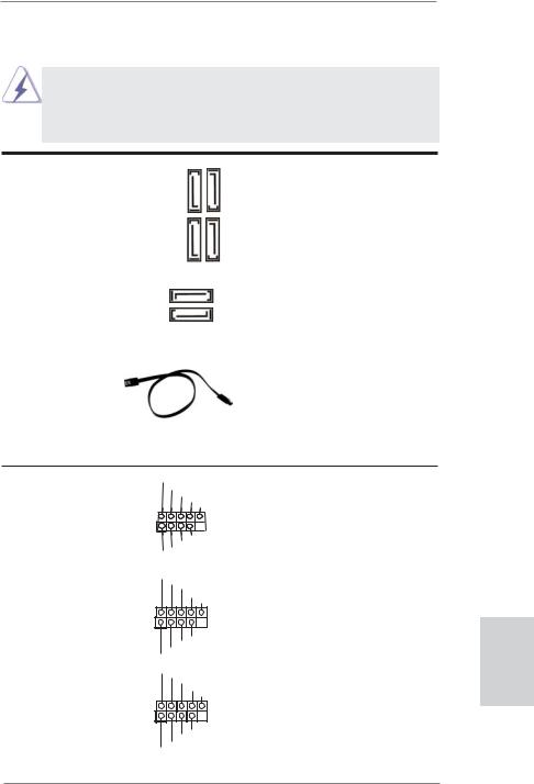
2.9 Onboard Headers and Connectors
Onboard headers and connectors are NOT jumpers. Do NOT place jumper caps over these headers and connectors. Placing jumper caps over the headers and connectors will cause permanent damage of the motherboard!
Serial ATA3 Connectors
(SATA3_1: see p.2, No. 18) (SATA3_2: see p.2, No. 17) (SATA3_3: see p.2, No. 13) (SATA3_4: see p.2, No. 12) (SATA3_5: see p.2, No. 10) (SATA3_6: see p.2, No. 11)
|
SATA3 5 |
SATA3 6 |
|
SATA3 3 |
SATA3 4 |
|
SATA3_2 |
These six Serial ATA3
(SATA3) connectors support SATA data cables for internal storage devices. The current SATA3 interface allows up to
6.0 Gb/s data transfer rate.
|
SATA3_1 |
|
|
Serial ATA (SATA) |
Either end of the SATA data |
|
Data Cable |
cable can be connected to the |
|
(Optional) |
SATA / SATAII / SATA3 hard |
|
disk or the SATA3 connector on |
|
|
this motherboard. |
|
USB 2.0 Headers |
USB_PWR |
|
|
(9-pin USB_6_7) |
P-7 |
|
|
P+7 |
||
|
GND |
||
|
(see p.2 No. 23) |
DUMMY |
|
|
1 |
||
|
GND |
||
|
P+6 |
||
|
P-6 |
||
|
USB_PWR |
||
|
(9-pin USB_8_9) |
USB_PWR |
|
|
P-9 |
||
|
(see p.2 No. 25) |
P+9 |
|
|
GND |
||
|
DUMMY |
||
|
1 |
||
|
GND |
||
|
P+8 |
||
|
P-8 |
||
|
USB_PWR |
||
|
(9-pin USB_10_11) |
USB_PWR |
|
|
P-11 |
||
|
(see p.2 No. 26) |
||
|
P+11 |
||
|
GND |
||
|
DUMMY |
||
|
1 |
||
|
GND |
||
|
P+10 |
||
|
P-10 |
||
|
USB_PWR |
Besides six default USB 2.0 ports on the I/O panel, there are three USB 2.0 headers on this motherboard. Each USB 2.0 header can support two USB 2.0 ports.
23
English
ASRock 970 Pro3 Motherboard

|
Infrared Module Header |
IRTX |
||||||||
|
(5-pin IR1) |
+5VSB |
||||||||
|
DUMMY |
|||||||||
|
(see p.2 No. 27) |
1 |
||||||||
|
GND |
|||||||||
|
IRRX |
This header supports an optional wireless transmitting and receiving infrared module.
|
Consumer Infrared Module Header |
1 |
||||||||
|
(4-pin CIR1) |
GND |
||||||||
|
IRTX |
|||||||||
|
(see p.2 No. 24) |
IRRX |
||||||||
|
ATX+5VSB |
This header can be used to connect the remote controller receiver.
|
Front Panel Audio Header |
GND |
|||||||||||
|
(9-pin HD_AUDIO1) |
PRESENCE# |
|||||||||||
|
MIC_RET |
||||||||||||
|
OUT_RET |
||||||||||||
|
(see p.2 No. 30) |
1 |
|||||||||||
|
OUT2_L |
||||||||||||
|
J_SENSE |
||||||||||||
|
OUT2_R |
||||||||||||
|
MIC2_R |
||||||||||||
|
MIC2_L |
This is an interface for the front panel audio cable that allows convenient connection and control of audio devices.
1.High Definition Audio supports Jack Sensing, but the panel wire on the chassis must support HDA to function correctly. Please follow the instruction in our manual and chassis manual to install your system.
2.If you use AC’97 audio panel, please install it to the front panel audio header as below:
A.Connect Mic_IN (MIC) to MIC2_L.
B.Connect Audio_R (RIN) to OUT2_R and Audio_L (LIN) to OUT2_L.
C.Connect Ground (GND) to Ground (GND).
D.MIC_RET and OUT_RET are for HD audio panel only. You don’t need to connect them for AC’97 audio panel.
E.To activate the front mic.
For Windows® XP / XP 64-bit OS:
Select “Mixer”. Select “Recorder”. Then click “FrontMic”. For Windows® 7 / 7 64-bit / VistaTM / VistaTM 64-bit OS:
Go to the «FrontMic» Tab in the Realtek Control panel. Adjust “Recording Volume”.
|
System Panel Header |
This header accommodates |
|
(9-pin PANEL1) |
several system front panel |
|
(see p.2 No. 22) |
functions. |
English
Connect the power switch, reset switch and system status indicator on the chassis to this header according to the pin assignments below. Note the positive and negative pins before connecting the cables.
24
ASRock 970 Pro3 Motherboard

PWRBTN (Power Switch):
Connect to the power switch on the chassis front panel. You may configure the way to turn off your system using the power switch.
RESET (Reset Switch):
Connect to the reset switch on the chassis front panel. Press the reset switch to restart the computer if the computer freezes and fails to perform a normal restart.
PLED (System Power LED):
Connect to the power status indicator on the chassis front panel. The LED is on when the system is operating. The LED keeps blinking when the sys-tem is in S1 sleep state. The LED is off when the system is in S3/S4 sleep state or powered off (S5).
HDLED (Hard Drive Activity LED):
Connect to the hard drive activity LED on the chassis front panel. The LED is on when the hard drive is reading or writing data.
The front panel design may differ by chassis. A front panel module mainly consists of power switch, reset switch, power LED, hard drive activity LED, speaker and etc. When connecting your chassis front panel module to this header, make sure the wire assignments and the pin assign-ments are matched correctly.
|
Chassis Speaker Header |
1 |
Please connect the chassis |
||
|
(4-pin SPEAKER 1) |
DUMMY |
speaker to this header. |
||
|
SPEAKER |
||||
|
(see p.2 No. 20) |
+5V DUMMY |
|||
Power LED Header
PLED-
|
(see p.2 No. 19) |
PLED+ |
|
PLED+ |
Please connect the chassis power LED to this header to indicate system power status. The LED is on when the system is operating. The LED keeps blinking in S1 state. The LED is off in S3/S4 state or S5 state (power off).
|
Chassis and Power Fan Connectors |
Please connect the fan cables |
|
|
(4-pin CHA_FAN1) |
to the fan connectors and |
|
|
(see p.2 No. 37) |
match the black wire to the |
|
|
ground pin. |
||
|
(3-pin CHA_FAN2) |
||
|
(see p.2 No. 21) |
||
|
(3-pin PWR_FAN1) |
GND |
|
|
+12V |
||
|
(see p.2 No. 9) |
||
|
PWR_FAN_SPEED |
25
English
ASRock 970 Pro3 Motherboard

English
|
CPU Fan Connectors |
FAN_SPEED_CONTROL |
Please connect the CPU fan |
||||||||||
|
(4-pin CPU_FAN1) |
CPU_FAN_SPEED |
cable to the connector and |
||||||||||
|
(see p.2 |
No. 5) |
+12V |
match the black wire to the |
|||||||||
|
GND |
||||||||||||
|
1 |
2 |
3 |
4 |
ground pin. |
||||||||
|
Though this motherboard provides 4-Pin CPU fan (Quiet Fan) support, the 3-Pin |
||||||||||||
|
CPU fan still can work successfully even without the fan speed control function. |
||||||||||||
|
If you plan to connect the 3-Pin CPU fan to the CPU fan connector on this |
||||||||||||
|
motherboard, please connect it to Pin 1-3. |
||||||||||||
|
Pin 1-3 Connected |
||||||||||||
|
3-Pin Fan Installation |
||||||||||||
|
(3-pin CPU_FAN2) |
GND |
|||||||||||
|
(see p.2 |
No. 4) |
+12V |
||||||||||
|
CPU_FAN_SPEED |
||||||||||||
|
ATX Power Connector |
12 |
24 |
Please connect an ATX power |
|||||||||
|
(24-pin ATXPWR1) |
supply to this connector. |
|||||||||||
|
(see p.2 |
No. |
|||||||||||
|
1 |
13 |
|||||||||||
|
Though this motherboard provides 24-pin ATX power connector, |
12 |
24 |
||||||||||
|
it can still work if you adopt a traditional 20-pin ATX power supply. |
||||||||||||
|
To use the 20-pin ATX power supply, please plug your power |
||||||||||||
|
supply along with Pin 1 and Pin 13. |
||||||||||||
|
20-Pin ATX Power Supply Installation |
1 |
13 |
||||||||||
|
ATX 12V Power Connector |
5 |
1 |
Please connect an ATX 12V |
|||||||||
|
power supply to this connector. |
||||||||||||
|
(8-pin ATX12V1) |
||||||||||||
|
(see p.2 |
No. 1) |
8 |
4 |
|||||||||
|
Though this motherboard provides 8-pin ATX 12V power connector, it can still work |
||||||||||||
|
if you adopt a traditional 4-pin ATX 12V power supply. To use the |
5 |
1 |
||||||||||
|
4-pin ATX power supply, please plug your power supply along with |
||||||||||||
|
Pin 1 and Pin 5. |
4-Pin ATX 12V Power Supply Installation |
8 |
4 |
|||||||||

26
ASRock 970 Pro3 Motherboard
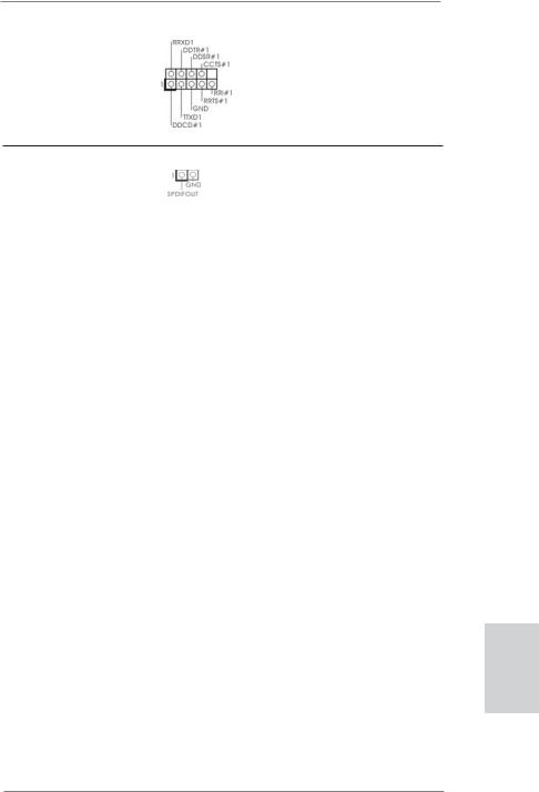
|
Serial port Header |
This COM1 header supports a |
|
(9-pin COM1) |
serial port module. |
|
(see p.2 No.28) |
|
HDMI_SPDIF Header |
HDMI_SPDIF header, providing |
|
(2-pin HDMI_SPDIF1) |
SPDIF audio output to HDMI |
|
(see p.2 No. 29) |
VGA card, allows the system to |
|
connect HDMI Digital TV/ |
|
|
projector/LCD devices. Please |
|
|
connect the HDMI_SPDIF |
|
|
connector of HDMI VGA card to |
|
|
this header. |
English
27
ASRock 970 Pro3 Motherboard

2.10 Driver Installation Guide
To install the drivers to your system, please insert the support CD to your optical drive first. Then, the drivers compatible to your system can be auto-detected and listed on the support CD driver page. Please follow the order from up to bottom side to install those required drivers. Therefore, the drivers you install can work properly.
2.11 Installing Windows® 7 / 7 64-bit / VistaTM / VistaTM 64-bit / XP / XP 64-bit With RAID Functions
If you want to install Windows® 7 / 7 64-bit / VistaTM / VistaTM 64-bit / XP / XP 64bit on your SATA3 HDDs with RAID functions, please refer to the document at the following path in the Support CD for detailed procedures:
.. RAID Installation Guide
2.12 Installing Windows® 7 / 7 64-bit / VistaTM / VistaTM 64-bit / XP / XP 64-bit Without RAID Functions
If you want to install Windows® 7 / 7 64-bit / VistaTM / VistaTM 64-bit / XP / XP 64-bit OS on your SATA3 HDDs without RAID functions, please follow below procedures according to the OS you install.
2.12.1 Installing Windows® XP / XP 64-bit Without RAID Functions
If you want to install Windows® XP / XP 64-bit on your SATA3 HDDs without RAID functions, please follow below steps.
Using SATA3 HDDs without NCQ and Hot Plug functions (IDE mode)
STEP 1: Set up UEFI.
A.Enter UEFI SETUP UTILITY  Advanced screen
  Storage Configuration.
B.Set the “SATA Mode” option to [IDE].
STEP 2: Install Windows® XP / XP 64-bit OS on your system.
English
28
ASRock 970 Pro3 Motherboard

2.12.2 Installing Windows® 7 / 7 64-bit / VistaTM / VistaTM 64-bit Without RAID Functions
If you want to install Windows® 7 / 7 64-bit / VistaTM / VistaTM 64-bit on your SATA3 HDDs without RAID functions, please follow below steps.
Using SATA3 HDDs without NCQ and Hot Plug functions (IDE mode)
STEP 1: Set up UEFI.
A.Enter UEFI SETUP UTILITY  Advanced screen
  Storage Configuration.
B.Set the “SATA Mode” option to [IDE].
STEP 2: Install Windows® 7 / 7 64-bit / VistaTM / VistaTM 64-bit OS on your system.
Using SATA3 HDDs with NCQ and Hot Plug functions (AHCI mode)
STEP 1: Set up UEFI.
A.Enter UEFI SETUP UTILITY  Advanced screen
  Storage Configuration.
B.Set the “SATA Mode” option to [AHCI].
STEP 2: Install Windows® 7 / 7 64-bit / VistaTM / VistaTM 64-bit OS on your system.
2.13 Untied Overclocking Technology
This motherboard supports Untied Overclocking Technology, which means during overclocking, FSB enjoys better margin due to fixed PCI / PCIE buses. Before you enable Untied Overclocking function, please enter “Overclock Mode” option of UEFI setup to set the selection from [Auto] to [Manual]. Therefore, CPU FSB is untied during overclocking, but PCI / PCIE buses are in the fixed mode so that FSB can operate under a more stable overclocking environment.
Please refer to the warning on page 7 for the possible overclocking risk before you apply Untied Overclocking Technology.
English
29
ASRock 970 Pro3 Motherboard

3. BIOS Information
The Flash Memory on the motherboard stores BIOS Setup Utility. When you start up the computer, please press <F2> or <Del> during the Power-On-Self-Test (POST) to enter BIOS Setup utility; otherwise, POST continues with its test routines. If you wish to enter BIOS Setup after POST, please restart the system by pressing <Ctl> + <Alt> + <Delete>, or pressing the reset button on the system chassis. The BIOS Setup program is designed to be user-friendly. It is a menu-driven program, which allows you to scroll through its various sub-menus and to select among the predetermined choices. For the detailed information about BIOS Setup, please refer to the User Manual (PDF file) contained in the Support CD.
4. Software Support CD information
This motherboard supports various Microsoft® Windows® operating systems: 7 / 7 64-bit / VistaTM / VistaTM 64-bit / XP / XP 64-bit. The Support CD that came with the motherboard contains necessary drivers and useful utilities that will enhance motherboard features. To begin using the Support CD, insert the CD into your CD-ROM drive. It will display the Main Menu automatically if “AUTORUN” is enabled in your computer. If the Main Menu does not appear automatically, locate and double-click on the file “ASSETUP.EXE” from the BIN folder in the Support CD to display the menus.
English
30
ASRock 970 Pro3 Motherboard
![]()
1. Einführung
Wir danken Ihnen für den Kauf des ASRock 970 Pro3 Motherboard, ein zuverlässiges Produkt, welches unter den ständigen, strengen Qualitätskontrollen von ASRock gefertigt wurde. Es bietet Ihnen exzellente Leistung und robustes Design, gemäß der Verpflichtung von ASRock zu Qualität und Halbarkeit. Diese Schnellinstallationsanleitung führt in das Motherboard und die schrittweise Installation ein. Details über das Motherboard finden Sie in der Bedienungsanleitung auf der Support-CD.
Da sich Motherboard-Spezifikationen und BIOS-Software verändern können, kann der Inhalt dieses Handbuches ebenfalls jederzeit geändert werden. Für den Fall, dass sich Änderungen an diesem Handbuch ergeben, wird eine neue Version auf der ASRock-Website, ohne weitere Ankündigung, verfügbar sein. Die neuesten Grafikkarten und unterstützten CPUs sind auch auf der ASRock-Website aufgelistet.
ASRock-Website: http://www.asrock.com
Wenn Sie technische Unterstützung zu Ihrem Motherboard oder spezifische Informationen zu Ihrem Modell benötigen, besuchen Sie bitte unsere Webseite:
www.asrock.com/support/index.asp
1.1 Kartoninhalt
ASRock 970 Pro3 Motherboard
(ATX-Formfaktor: 30.5 cm x 20.8 cm; 12.0 Zoll x 8.2 Zoll)
ASRock 970 Pro3 Schnellinstallationsanleitung
ASRock 970 Pro3 Support-CD
Zwei Serial ATA (SATA) -Datenkabel (optional)
Ein I/O Shield
ASRock erinnert…
Zur besseren Leistung unter Windows® 7 / 7, 64 Bit / VistaTM / VistaTM 64 Bit empfehlen wir, die Speicherkonfiguration im BIOS auf den AHCIModus einzustellen. Hinweise zu den BIOS-Einstellungen finden Sie in der Bedienungsanleitung auf der mitgelieferten CD.
Deutsch
31
ASRock 970 Pro3 Motherboard

1.2 Spezifikationen
|
Plattform |
— ATX-Formfaktor: 30.5 cm x 20.8 cm; 12.0 Zoll x 8.2 Zoll |
|
— Alle Feste Kondensatordesign |
|
|
CPU |
— Unterstützung von Socket AM3+-Prozessoren |
|
— Unterstützung von Socket AM3-Prozessoren: AMD |
|
|
PhenomTM II X6 / X4 / X3 / X2 (außer 920 / 940) / Athlon X4 / |
|
|
X3 / X2 / Sempron-Prozessor |
|
|
— Acht-Kern-CPU-bereit |
|
|
— Unterstützt UCC (Unlock CPU Core) (siehe VORSICHT 1) |
|
|
— 4 + 1-Stromphasendesign |
|
|
— Unterstützt CPU bis 140W |
|
|
— Unterstützt Cool ‘n’ QuietTM-Technologie von AMD |
|
|
— FSB 2400 MHz (4.8 GT/s) |
|
|
— Unterstützt Untied-Übertaktungstechnologie |
|
|
(siehe VORSICHT 2) |
|
|
— Unterstützt Hyper-Transport- 3.0 Technologie (HT 3.0) |
|
|
Chipsatz |
— Northbridge: AMD 970 |
|
— Southbridge: AMD SB950 |
|
|
Speicher |
— Unterstützung von Dual-Kanal-Speichertechnologie |
|
(siehe VORSICHT 3) |
|
|
— 4 x Steckplätze für DDR3 |
|
|
— Unterstützt DDR3 2100(OC)1866(OC)/1800(OC)/1600(OC) |
|
|
/1333/1066/800 non-ECC, ungepufferter Speicher |
|
|
(siehe VORSICHT 4) |
|
|
— Max. Kapazität des Systemspeichers: 32GB |
|
|
(siehe VORSICHT 5) |
|
|
Erweiterungs- |
— 2 x PCI-Express-2.0-x16-Steckplätze |
|
Steckplätze |
(PCIE2: x16-Modus; PCIE3: x4-Modus) |
|
— 1 x PCI Express 2.0 x1-Steckplätze |
|
|
— 2 x PCI -Steckplätze |
|
|
— Unterstützt AMD Quad CrossFireXTM und CrossFireXTM |
|
|
Audio |
— 7.1 CH HD Audio mit dem Inhalt Schutz |
|
(Realtek ALC892 Audio Codec) |
|
|
— Premium Blu-ray-Audio-Unterstützung |
|
|
— Unterstützt THX TruStudioTM |
|
|
LAN |
— PCIE x1 Gigabit LAN 10/100/1000 Mb/s |
|
— Realtek RTL8111E |
|
|
— Unterstützt Wake-On-LAN |
|
|
— Unterstützt LAN-Kabelerkennung |
|
|
— Unterstützt energieeffizientes Ethernet 802.3az |
ASRock 970 Pro3 Motherboard

|
— Unterstützt PXE |
|
|
E/A-Anschlüsse |
I/O Panel |
|
an der |
— 1 x PS/2-Mausanschluss |
|
Rückseite |
— 1 x PS/2-Tastaturanschluss |
|
— 6 x Standard-USB 2.0-Anschlüsse |
|
|
— 2 x Standard-USB 3.0-Anschlüsse |
|
|
— 1 x RJ-45 LAN Port mit LED (ACT/LINK LED und SPEED |
|
|
LED) |
|
|
— HD Audiobuchse: Lautsprecher seitlich / Lautsprecher |
|
|
hinten / Mitte/Bass / Audioeingang/ Lautsprecher vorne / |
|
|
Mikrofon (siehe VORSICHT 6) |
|
|
SATA3 |
— 6 x SATA 3-Anschluss mit 6,0 Gb/s, unterstützt RAID- |
|
(RAID 0, RAID 1, RAID 5 und RAID 10), NCQ-, AHCIund |
|
|
„Hot Plugging“-Funktionen |
|
|
USB3.0 |
— 2 x USB 3.0-Ports an der Rückseite durch Etron EJ168A, |
|
unterstützt USB 1.0/2.0/3.0 mit bis zu 5 Gb/s |
|
|
Anschlüsse |
— 6 x SATA3 6,0 GB/s-Anschlüsse |
|
— 1 x Infrarot-Modul-Header |
|
|
— 1 x Consumer Infrarot-Modul-Header |
|
|
— 1 x COM-Anschluss-Header |
|
|
— 1 x HDMI_SPDIF-Anschluss |
|
|
— 1 x Betriebs-LED-Header |
|
|
— 2 x CPUlüfter-Anschluss (1 x 4-pin, 1 x 3-pin) |
|
|
— 2 x Gehäuselüfter-Anschluss (1 x 4-pin, 1 x 3-pin) |
|
|
— 1 x Stromlüfter-Anschluss (3-pin) |
|
|
— 24-pin ATX-Netz-Header |
|
|
— 8-pin anschluss für 12V-ATX-Netzteil |
|
|
— Anschluss für Audio auf der Gehäusevorderseite |
|
|
— 3 x USB 2.0-Anschlüsse (Unterstützung 6 zusätzlicher |
|
|
USB 2.0-Anschlüsse) |
|
|
BIOS |
— 32Mb AMIs Legal BIOS UEFI mit GUI-Unterstützung |
|
— Unterstützung für “Plug and Play” |
|
|
— ACPI 1.1-Weckfunktionen |
|
|
— JumperFree-Modus |
|
|
— SMBIOS 2.3.1 |
|
|
— CPU, VCCM, NB, SB Stromspannung Multianpassung |
|
|
Support-CD |
— Treiber, Dienstprogramme, Antivirussoftware |
|
(Probeversion), CyberLink MediaEspresso 6.5-Testversion, |
|
|
AMD OverDriveTM-Dienstprogramm, AMD Fusion, AMD |
|
|
Fusion Media Explorer, ASRock MAGIX-Multimedia-Suite — |
|
|
OEM |
|
ASRock 970 Pro3 Motherboard

|
Einzigartige |
— ASRock Extreme Tuning Utility (AXTU) |
|
Eigenschaft |
(siehe VORSICHT 7) |
|
— ASRock Sofortstart |
|
|
— ASRock Instant Flash (siehe VORSICHT 8) |
|
|
— ASRock APP Charger (siehe VORSICHT 9) |
|
|
— ASRock SmartView (siehe VORSICHT 10) |
|
|
— ASRock XFast USB (siehe VORSICHT 11) |
|
|
— ASRock XFast LAN (siehe VORSICHT 12) |
|
|
— ASRock XFast RAM (siehe VORSICHT 13) |
|
|
— ASRock Crashless BIOS (siehe VORSICHT 14) |
|
|
— ASRock OMG (Online Management Guard) |
|
|
(siehe VORSICHT 15) |
|
|
— ASRock Internet Flash (siehe VORSICHT 16) |
|
|
— ASRock ein/aus-Wiedergabetechnologie |
|
|
(siehe VORSICHT 17) |
|
|
— Hybrid Booster: |
|
|
— Schrittloser CPU-Frequenz-Kontrolle |
|
|
(siehe VORSICHT 18) |
|
|
— ASRock U-COP (siehe VORSICHT 19) |
|
|
— Boot Failure Guard (B.F.G. – Systemstartfehlerschutz) |
|
|
— Turbo UCC |
|
|
Hardware Monitor |
— CPU-Temperatursensor |
|
— Motherboardtemperaturerkennung |
|
|
— Drehzahlmessung für CPU/Gehäuse/Stromlüfter |
|
|
— CPU-/Gehäuselüftergeräuschdämpfung |
|
|
— Mehrstufige Geschwindigkeitsteuerung für CPU-/ |
|
|
Gehäuselüfter |
|
|
— Spannungsüberwachung: +12V, +5V, +3.3V, Vcore |
|
|
Betriebssysteme |
— Unterstützt Microsoft® Windows® 7 / 7 64-Bit / VistaTM / |
|
VistaTM 64-Bit / XP / XP 64-Bit (siehe VORSICHT 20) |
|
|
Zertifizierungen |
— FCC, CE, WHQL |
—Gemäß Ökodesign-Richtlinie (ErP/EuP) (Stromversorgung gemäß Ökodesign-Richtlinie (ErP/EuP) erforderlich) (siehe VORSICHT 21)
*Für die ausführliche Produktinformation, besuchen Sie bitte unsere Website: http://www.asrock.com
ASRock 970 Pro3 Motherboard

WARNUNG
Beachten Sie bitte, dass Overclocking, einschließlich der Einstellung im BIOS, Anwenden der Untied Overclocking-Technologie oder Verwenden von Overclocking-Werkzeugen von Dritten, mit einem gewissen Risiko behaftet ist. Overclocking kann sich nachteilig auf die Stabilität Ihres Systems auswirken oder sogar Komponenten und Geräte Ihres Systems beschädigen. Es geschieht dann auf eigene Gefahr und auf Ihre Kosten. Wir übernehmen keine Verantwortung für mögliche Schäden, die aufgrund von Overclocking verursacht wurden.
VORSICHT!
1.Die ASRock UCC-Funktion (Unlock CPU Core; zu Deutsch: CPU-Kern freigeben) vereinfacht die AMD-CPU-Aktivierung. Zur Freigabe des zusätzlichen CPU-Kerns müssen Sie lediglich die UEFI-Option „Unlock CPU Core“ (zu Deutsch: CPU-Kern freigeben) umschalten – schon profitieren Sie von einem Leistungsschub. Wenn die UCC-Funktion aktiviert ist, rüstet die DualCoreoder Triple-Core-CPU auf eine Quad-Core-CPU auf – einige CPUs (inklusive Quad-Core) können zudem die L3-Cache-Größe auf bis zu 6 MB anheben; das bedeutet verbesserte CPU-Leistung zu einem geringeren Preis. Bitte beachten Sie, dass die UCC-Funktion nur bei AM3/AM3+-CPUs einsetzbar ist; die Unterstützung besteht jedoch aufgrund möglicher Fehlfunktionen des verborgenen Kerns einiger CPUs auch nicht zwangsläufig bei jeder AM3/AM3+-CPU.
2.Dieses Motherboard unterstützt die Untied-Übertaktungstechnologie. Unter “Entkoppelte Übertaktungstechnologie” auf Seite 29 finden Sie detaillierte Informationen.
3.Dieses Motherboard unterstützt Dual-Kanal-Speichertechnologie. Vor Implementierung der Dual-Kanal-Speichertechnologie müssen Sie die Installationsanleitung für die Speichermodule auf Seite 13 zwecks richtiger Installation gelesen haben.
4.Ob die Speichergeschwindigkeit 2100/1866/1800/1600 MHz unterstützt wird, hängt von der von Ihnen eingesetzten AM3/AM3+-CPU ab. Schauen Sie bitte auf unseren Internetseiten in der Liste mit unterstützten Speichermodulen nach, wenn Sie DDR3 2100/1866/1800/1600-Spei- chermodule einsetzen möchten. AM3+ CPU unterstützt DDR3 1866 ohne Übertaktung (OC Mode).
ASRock-Internetseite: http://www.asrock.com
5.Durch Betriebssystem-Einschränkungen kann die tatsächliche Speichergröße weniger als 4 GB betragen, da unter Windows® 7 / Vista™ / XP etwas Speicher zur Nutzung durch das System reserviert wird. Unter Windows® OS mit 64-Bit-CPU besteht diese Einschränkung nicht. Sie können ASRock XFast RAM zur Nutzung des Speichers, den Windows® nicht verwenden kann, einsetzen.
35
Deutsch
ASRock 970 Pro3 Motherboard

6.Der Mikrofoneingang dieses Motherboards unterstützt Stereound MonoModi. Der Audioausgang dieses Motherboards unterstützt 2-Kanal-, 4-Kanal-, 6-Kanal- und 8-Kanal-Modi. Stellen Sie die richtige Verbindung anhand der Tabelle auf Seite 3 her.
7.ASRock Extreme Tuning Utility (AXTU) ist ein Alles-in-einem- Werkzeug zur Feineinstellung verschiedener Systemfunktionen an einer benutzerfreundlichen Schnittstelle; diese beinhaltet HardwareÜberwachung, Lüftersteuerung, Übertaktung, OC DNA und IES. Über die Hardware-Überwachung können Sie die Hauptsystemdaten einsehen. Die Lüftersteuerung zeigt Ihnen zur Anpassung Lüftergeschwindigkeit und Temperatur an. Bei der Übertaktung können Sie die CPU-Frequenz zur Erzielung optimaler Systemleistung übertakten. OC DNA ermöglicht Ihnen die Speicherung Ihrer OCEinstellungen als Profi l, welches Sie mit Freunden teilen können. Ihre Freunde können das OC-Profi l dann in ihrem System laden und so die gleichen OC-Einstellungen erzielen. Per IES (Intelligent Energy Saver) kann der Spannungsregulator bei Inaktivität der CPU-Kerne die Anzahl an Ausgangsphasen zur Steigerung der Effi zienz reduzieren – ohne die
Rechenleistung zu beeinträchtigen. Hinweise zur Bedienung der ASRock Extreme Tuning Utility (AXTU) fi nden Sie auf unserer Webseite. ASRock-Webseite: http://www.asrock.com
8.ASRock Instant Flash ist ein im Flash-ROM eingebettetes BIOS-Flash- Programm. Mithilfe dieses praktischen BIOS-Aktualisierungswerkzeugs können Sie das System-BIOS aktualisieren, ohne dafür zuerst Betriebssysteme wie MS-DOS oder Windows® aufrufen zu müssen. Mit diesem Programm bekommen Sie durch Drücken der <F6>-Taste während des POST-Vorgangs oder durch Drücken der <F2>-Taste im BIOS-Setup- Menü Zugang zu ASRock Instant Flash. Sie brauchen dieses Werkzeug einfach nur zu starten und die neue BIOS-Datei auf Ihrem USB-Flash- Laufwerk, Diskettenlaufwerk oder der Festplatte zu
speichern, und schon können Sie Ihr BIOS mit nur wenigen Klickvorgängen ohne Bereitstellung einer zusätzlichen Diskette oder eines anderen komplizierten Flash-Programms aktualisieren. Achten Sie darauf, dass das USB-Flash-Laufwerk oder die Festplatte das Dateisystem FAT32/16/12 benutzen muss.
9.Wenn Sie nach einer schnelleren, weniger eingeschränkten Möglichkeit zur Aufladung Ihrer Apple-Geräte (z. B. iPhone/iPad/iPod touch) suchen, bietet ASRock Ihnen eine wunderbare Lösung – den ASRock APP Charger. Installieren Sie einfach den ASRock APP Charger-Treiber; dadurch lädt sich Ihr iPhone wesentlich schneller über einen Computer auf – genaugenommen bis zu 40 % schneller als zuvor. Der ASRock APP Charger ermöglicht Ihnen die schnelle Aufladung mehrerer Apple-Geräte gleichzeitig; der Ladevorgang wird sogar dann fortgesetzt, wenn der PC den Ruhezustand (S1), Suspend to RAM-Modus (S3) oder Tiefschlafmodus (S4) aufruft oder ausgeschaltet wird (S5). Nach der
Installation des APP Charger-Treibers können Sie im Handumdrehen das
ASRock 970 Pro3 Motherboard

großartigste Ladeerlebnis überhaupt genießen.
ASRock-Webseite: http://www.asrock.com/Feature/AppCharger/index. asp
10.SmartView, eine neue Internetbrowserfunktion, ist eine intelligente IEStartseite, die meist besuchte Internetseiten, Ihren Browserverlauf, Facebook-Freunde und Nachrichten in Echtzeit miteinander kombiniert: In einer speziellen Ansicht, die das Internet noch angenehmer und aufregender macht. ASRock-Motherboards werden exklusiv mit der Smart- View-Software geliefert, die auch dafur sorgt, dass Sie immer mit Ihren Freunden in Verbindung bleiben. Die SmartView-Funktionen konnen Sie mit den Windows®-Betriebssystemen 7 / 7, 64 Bit / VistaTM / VistaTM 64 Bit und dem Internet Explorer ab Version 8 nutzen.
ASRock-Website: http://www.asrock.com/Feature/SmartView/index.asp
11.ASRocks XFast USB dient der Steigerung der Leistungsfähigkeit Ihrer USB-Speichergeräte. Die Leistung kann je nach Eigenschaften des Gerätes variieren.
12.ASRock XFast LAN bietet einen schnelleren Internetzugang mit den nachfolgenden Vorteilen. LAN-Anwendungspriorisierung: Hiermit konfigurieren Sie auf ideale Weise Ihre Anwendungspriorität und/oder fügen neue Programme hinzu. Niedrigere Latenzzeit bei Spielen: Nach Einstellung einer höheren Online-Gamepriorität kann hiermit die Latenzzeit bei Spielen herabgesetzt werden. Datenverkehrsgestaltung: Sie können Youtube-Videos in HD anzeigen und gleichzeitig Dateien herunterladen. Echtzeitanalyse Ihrer Daten: Über das Statusfenster können Sie schnell ermitteln, welche Datenströme zur Zeit übertragen werden.
13.ASRock XFast RAM ist eine neue Funktion, die beim ASRock Extreme Tuning Utility (AXTU) integriert ist. Sie ermöglicht die vollständige Nutzung des Speicherplatzes, der unter Windows®-Betriebssystemen mit 32-Bit-CPU nicht verwendet werden kann. ASRock XFast RAM verkürzt die Ladezeit zuvor besuchter Webseiten, was das Surfen im Internet mehr denn je beschleunigt. Auch die Arbeit mit Adobe Photoshop erfolgt fünfmal schneller. Ein weiterer Vorteil von ASRock XFast RAM liegt in der Reduzierung der Häufigkeit des Zugriffs auf SSDs bzw. HDDs zur Verlän gerung deren Lebenszeit.
14.ASRock Crashless BIOS ermöglicht Benutzern die Aktualisierung ihres BIOS, ohne dass diese Fehler fürchten müssen. Falls während der BIOSAktualisierung ein Stromausfall auftritt, setzt ASRock Crashless BIOS die BIOS-Aktualisierung automatisch fort, sobald die Stromversorgung wiederhergestellt ist. Bitte beachten Sie, dass alle BIOS-Dateien zuerst im Stammverzeichnis Ihres USB-Datenträgers platziert werden müssen. Diese Funktion wird nur von USB 2.0-Ports unterstützt.
15.Per OMG können Administratoren eine Internet-Sperrstunde einrichten oder den Internetzugang auf bestimmte Zeiten beschränken. Sie können die Startund Endzeiten festlegen, zu denen anderen Benutzern der Zugriff auf das Internet gewährt werden soll. Damit Benutzer OMG nicht umgehen können, sind Gästekonten ohne Berechtigung zur Modifikation der Systemzeiten erforderlich.
ASRock 970 Pro3 Motherboard

16.Die Internet Flash sucht nach verfügbaren UEFI-Aktualisierungen auf unseren Servern. Mit anderen Worten: Das System erkennt aktuellste UEFI-Firmware auf unseren Servern automatisch und aktualisiert die Geräte-Firmware ohne Zutun von Windows. Bitte beachten Sie, dass diese Funktion nur mit DHCP-konfigurierten Computern möglich ist.
17.Durch die ASRock ein/aus-Wiedergabetechnologie können Sie großartige Klangerlebnisse von portablen Audiogeräten, wie z. B. MP3-Playern oder Mobiltelefonen, an Ihrem PC genießen – selbst wenn der PC ausgeschaltet ist (oder sich im ACPI S5-Modus befindet)! Dieses Motherboard wird zudem mit einem kostenlosen Audiokabel (3,5 mm, Klinke) (optional) geliefert, was eine IT-Umgebung von höchster Benutzerfreundlichkeit gewährleistet.
18.Obwohl dieses Motherboard stufenlose Steuerung bietet, wird Overclocking nicht empfohlen. Frequenzen, die von den empfohlenen CPUBusfrequenzen abweichen, können Instabilität des Systems verursachen oder die CPU beschädigen.
19.Wird eine Überhitzung der CPU registriert, führt das System einen automatischen Shutdown durch. Bevor Sie das System neu starten, prüfen Sie bitte, ob der CPU-Lüfter am Motherboard richtig funktioniert, und stecken Sie bitte den Stromkabelstecker aus und dann wieder ein. Um die Wärmeableitung zu verbessern, bitte nicht vergessen, etwas Wärmeleitpaste zwischen CPU und Kühlkörper zu sprühen.
20.ASRock XFast RAM wird von Microsoft® Windows® XP / XP 64 Bit nicht unterstützt.
21.EuP steht für Energy Using Product und kennzeichnet die ÖkodesignRichtlinie, die von der Europäischen Gemeinschaft zur Festlegung des Energieverbrauchs von vollständigen Systemen in Kraft gesetzt wurde. Gemäß dieser Ökodesign-Richtlinie (EuP) muss der gesamte Netzstromverbrauch von vollständigen Systemen unter 1,00 Watt liegen, wenn sie ausgeschaltet sind. Um dem EuP-Standard zu entsprechen, sind ein EuP-fähiges Motherboard und eine EuP-fähige Stromversorgung erforderlich. Gemäß einer Empfehlung von Intel muss eine EuP-fähige Stromversorgung dem Standard entsprechen, was bedeutet, dass bei einem Stromverbrauch von 100 mA die 5-Volt-Standby-Energieeffizienz höher als 50% sein sollte. Für die Wahl einer EuP-fähigen Stromversorgung empfehlen wir Ihnen, weitere Details beim Hersteller der Stromversorgung abzufragen.
Deutsch
38
ASRock 970 Pro3 Motherboard

1.3 Einstellung der Jumper
Die Abbildung verdeutlicht, wie Jumper gesetzt werden. Werden Pins durch Jumperkappen verdeckt, ist der Jumper “gebrückt”. Werden keine Pins durch Jumperkappen verdeckt, ist der Jumper “offen”. Die Abbildung zeigt einen 3-Pin Jumper dessen Pin1 und Pin2 “gebrückt” sind, bzw. es befindet sich eine Jumper-Kappe auf diesen beiden Pins.
|
Jumper |
Einstellun |
|
|
CMOS löschen |
||
|
(CLRCMOS1, 3-Pin jumper) |
||
|
(siehe S.2, No. 16) |
Default- |
CMOS |
|
Einstellung |
löschen |
Hinweis: CLRCMOS1 erlaubt Ihnen das Löschen der CMOS-Daten. Diese beinhalten das System-Passwort, Datum, Zeit und die verschiedenen BIOS-Para- meter. Um die Systemparameter zu löschen und auf die Werkseinstellung zurückzusetzen, schalten Sie bitte den Computer ab und entfernen das Stromkabel. Benutzen Sie eine Jumperkappe, um die
Pin 2 und Pin 3 an CLRCMOS1 für 5 Sekunden kurzzuschließen. Bitte vergessen Sie nicht, den Jumper wieder zu entfernen, nachdem das CMOS gelöscht wurde. Bitte vergessen Sie nicht, den Jumper wieder zu entfernen, nachdem das CMOS gelöscht wurde. Wenn Sie den CMOSInhalt gleich nach dem Aktualisieren des BIOS löschen müssen, müssen Sie zuerst das System starten und dann wieder ausschalten, bevor Sie den CMOS-Inhalt löschen.
Deutsch
39
ASRock 970 Pro3 Motherboard

Deutsch
1.4 Anschlüsse
Anschlussleisten sind KEINE Jumper. Setzen Sie KEINE Jumperkappen auf die Pins der Anschlussleisten. Wenn Sie die Jumperkappen auf die Anschlüsse setzen, wird das Motherboard permanent beschädigt!
Anschluss
Seriell-ATA3-Anschlüsse
(SATA3_1: siehe S.2 — No. 18) (SATA3_2: siehe S.2 — No. 17) (SATA3_3: siehe S.2 — No. 13) (SATA3_4: siehe S.2 — No. 12) (SATA3_5: siehe S.2 — No. 10) (SATA3_6: siehe S.2 — No. 11)
Beschreibung
|
SATA3 5 |
SATA3 6 |
|
SATA3 3 |
SATA3 4 |
|
SATA3_2 |
Diese sechs Serial ATA3- (SATA3-)Verbínder unterstützten SATA-Datenkabel für interne Massenspeichergeräte. Die aktuelle SATA3Schnittstelle ermöglicht eine Datenübertragungsrate bis
6,0 Gb/s.
SATA3_1
|
Serial ATA- (SATA-) |
SJedes Ende des SATA |
|
Datenkabel |
Datenkabels kann an die |
|
(Option) |
SATA / SATAII / SATA3 |
|
Festplatte oder das SATA3 |
|
|
Verbindungsstück auf dieser |
|
|
Hauptplatine angeschlossen |
|
|
werden. |
|
USB 2.0-Header |
USB_PWR |
|
(9-pol. USB_6_7) |
P-7 |
|
P+7 |
|
|
GND |
|
|
(siehe S.2 — No. 23) |
DUMMY |
|
1 |
|
|
GND |
|
|
P+6 |
|
|
P-6 |
|
|
USB_PWR |
|
|
(9-pol. USB_8_9) |
USB_PWR |
|
P-9 |
|
|
P+9 |
|
|
(siehe S.2 — No. 25) |
GND |
|
DUMMY |
|
|
1 |
|
|
GND |
|
|
P+8 |
|
|
P-8 |
|
|
USB_PWR |
|
|
(9-pol. USB_10_11) |
USB_PWR |
|
(siehe S.2 — No. 26) |
P-11 |
|
P+11 |
|
|
GND |
|
|
DUMMY |
|
|
1 |
|
|
GND |
|
|
P+10 |
|
|
P-10 |
|
|
USB_PWR |
40
Zusätzlich zu den sechs üblichen USB 2.0-Ports an den I/O-Anschlüssen befinden sich drei USB 2.0- Anschlussleisten am Motherboard. Pro USB 2.0- Anschlussleiste werden zwei USB 2.0-Ports unterstützt.
ASRock 970 Pro3 Motherboard
![]()
|
Infrarot-Modul-Header |
IRTX |
Dieser Header unterstützt ein |
||||||||||||
|
(5-pin IR1) |
+5VSB |
optionales, drahtloses Sende- |
||||||||||||
|
DUMMY |
||||||||||||||
|
(siehe S.2 — No. 27) |
und Empfangs-Infrarotmodul. |
|||||||||||||
|
1 |
||||||||||||||
|
GND |
||||||||||||||
|
IRRX |
||||||||||||||
|
Consumer Infrared-Modul-Header |
Dieser Header kann zum |
|||||||||||||
|
(4-pin CIR1) |
1 |
Anschließen Remote- |
||||||||||||
|
GND |
||||||||||||||
|
IRTX |
Empfänger. |
|||||||||||||
|
(siehe S.2 — No. 24) |
ATX+5VSB |
|||||||||||||
|
IRRX |
|
Anschluss für Audio auf |
GND |
|
der Gehäusevorderseite |
PRESENCE# |
|
MIC_RET |
|
|
OUT_RET |
(9-Pin HD_AUDIO1)
OUT2_L
J_SENSE
OUT2_R
MIC2_R
MIC2_L
Dieses Interface zu einem Audio-Panel auf der Vorder seite Ihres Gehäuses, ermöglicht Ihnen eine bequeme Anschlussmöglichkeit und Kontrolle über Audio-Geräte.
1.High Definition Audio unterstützt Jack Sensing (automatische Erkennung falsch angeschlossener Geräte), wobei jedoch die Bildschirmverdrahtung am Gehäuse HDA unterstützen muss, um richtig zu funktionieren.
Beachten Sie bei der Installation im System die Anweisungen in unserem Handbuch und im Gehäusehandbuch.
2.Wenn Sie die AC’97-Audioleiste verwenden, installieren Sie diese wie nachstehend beschrieben an der Front-Audioanschlussleiste:
A.Schließen Sie Mic_IN (MIC) an MIC2_L an.
B.Schließen Sie Audio_R (RIN) an OUT2_R und Audio_L (LIN) an OUT2_L an.
C.Schließen Sie Ground (GND) an Ground (GND) an.
D.MIC_RET und OUT_RET sind nur für den HD-Audioanschluss gedacht. Diese Anschlüsse müssen nicht an die AC’97-Audioleiste angeschlossen werden.
E.So aktivieren Sie das Mikrofon an der Vorderseite.
Bei den Betriebssystemen Windows® XP / XP 64 Bit:
Wählen Sie „Mixer“. Wählen Sie „Recorder“ (Rekorder). Klicken Sie dann auf „FrontMic“ (Vorderes Mikrofon).
Bei den Betriebssystemen Windows® 7 / 7 64 Bit / VistaTM / VistaTM 64 Bit: Wählen Sie im Realtek-Bedienfeld die „FrontMic“ (Vorderes Mikrofon)- Registerkarte. Passen Sie die „Recording Volume“ (Aufnahmelautstärke) an.
|
System Panel-Header |
Dieser Header unterstützt |
|
(9-pin PANEL1) |
mehrere Funktion der |
|
(siehe S.2 — No. 22) |
Systemvorderseite. |
41
Deutsch
ASRock 970 Pro3 Motherboard

Deutsch
Schließen Sie die Ein-/Austaste, die Reset-Taste und die Systemstatusanzeige am Gehäuse an diesen Header an; befolgen Sie dabei die nachstehenden Hinweise zur Pinbelegung. Beachten Sie die positiven und negativen Pins, bevor Sie die Kabel anschließen.
PWRBTN (Ein-/Ausschalter):
Zum Anschließen des Ein-/Ausschalters an der Frontblende des Gehäu ses. Sie können konfigurieren, wie das System mit Hilfe des Ein-/Ausschalters ausgeschaltet werden können soll.
RESET (Reset-Taste):
Zum Anschließen der Reset-Taste an der Frontblende des Gehäuses. Mit der Reset-Taste können Sie den Computer im Falle eines Absturzes neu starten.
PLED (Systembetriebs-LED):
Zum Anschließen der Betriebsstatusanzeige an der Frontblende des Gehäuses. Die LED leuchtet, wenn das System in Betrieb ist. Die LED blinkt, wenn sich das System im Ruhezustand S1 befindet. Die LED schaltet sich aus, wenn sich das System in den Modi S3/S4 befindet oder ausgeschaltet ist (S5).
HDLED (Festplattenaktivitäts-LED):
Zum Anschließen der Festplattenaktivitäts-LED an der Frontblende des Gehäuses. Die LED leuchtet, wenn die Festplatte Daten liest oder schreibt.
Das Design der Frontblende kann je nach Gehäuse variiere. Ein Frontblendenmodul besteht hauptsächlich aus einer Ein-/Austaste, einer Reset-Taste, einer Betriebs-LED, einer Festplattenaktivitäts-LED, Lautsprechern, etc. Stellen Sie beim Anschließen des Frontblendenmoduls Ihres Gehäuses an diesem Header sicher, dass die Kabelund Pinbelegung korrekt übereinstimmen.
|
Gehäuselautsprecher-Header |
Schließen Sie den |
|
(4-pin SPEAKER1) |
Gehäuselautsprecher an |
|
(siehe S.2 — No. 20) |
diesen Header an. |
Betriebs-LED-Header
PLED-
|
(siehe S.2 — No. 19) |
PLED+ |
|
PLED+ |
Bitte schließen Sie die Betriebs-LED des Gehäuses zur Anzeige des Systembetriebsstatus an diesem Header an. Die LED leuchtet, wenn das System in Betrieb ist. Die LED blinkt im S1-Zustand. Im S3-/S4- oder S5-Zustand (ausgeschaltet) leuchtet die LED nicht.
42
ASRock 970 Pro3 Motherboard

|
Gehäuseund Stromlüfteranschlüsse |
Verbinden Sie die Lüfterkabel |
|
|
(4-pin CHA_FAN1) |
mit den Lüfteranschlüssen, |
|
|
(siehe S.2, No. 37) |
wobei der schwarze Draht an |
|
|
den Schutzleiterstift |
||
|
(3-pin CHA_FAN2) |
angeschlossenwird. |
|
|
(siehe S.2 — No. 21) |
||
|
(3-pin PWR_FAN1) |
GND |
|
|
(siehe S.2 — No. 9) |
+12V |
|
|
PWR_FAN_SPEED |
|
CPU-Lüfteranschluss |
FAN_SPEED_CONTROL |
|||
|
(4-pin CPU_FAN1) |
CPU_FAN_SPEED |
|||
|
(siehe S.2 — No. 5) |
+12V |
|||
|
GND |
||||
|
1 |
2 |
3 |
4 |
Verbinden Sie das CPU — Lüfterkabel mit diesem
Anschluss und passen Sie den schwarzen Draht dem Erdungsstift an.
(3-pin CPU_FAN2)
(siehe S.2 — No. 4)
Obwohl dieses Motherboard einen vierpoligen CPU-Lüfteranschluss (Quiet Fan) bietet, können auch CPU-Lüfter mit dreipoligem Anschluss angeschlossen werden; auch ohne Geschwindigkeitsregulierung. Wenn Sie einen dreipoligen CPU-Lüfter an den CPU-Lüferanschluss dieses Motherboards anschließen möchten, verbinden Sie ihn bitte mit den
Pins 1 – 3.
Pins 1–3 anschließen
Lüfter mit dreipoligem Anschluss installieren
GND +12V
CPU_FAN_SPEED
|
ATX-Netz-Header |
12 |
24 |
Verbinden Sie die ATX- |
|||
|
(24-pin ATXPWR1) |
Stromversorgung mit diesem |
|||||
|
(siehe S.2 — No. |
Header. |
|||||
|
1 |
13 |
|||||
|
Obwohl dieses Motherboard einen 24-pol. ATX- |
12 |
24 |
||||
|
Stromanschluss bietet, kann es auch mit einem |
||||||
|
modifizierten traditionellen 20-pol. ATX-Netzteil |
||||||
|
verwendet werden. Um ein 20-pol. ATX-Netzteil zu |
||||||
|
verwenden, stecken Sie den Stecker mit Pin 1 und |
||||||
|
Pin 13 ein. |
Installation eines 20-pol. ATX-Netzteils |
|||||
|
1 |
13 |
|||||
43
Deutsch
ASRock 970 Pro3 Motherboard

ATX 12V Anschluss
5 1
(8-pin ATX12V1)
Bitte schließen Sie an diesen Anschluss die ATX 12V
Stromversorgung an.
Obwohl diese Hauptplatine 8-Pin ATX 12V Stromanschluss zur Verfügung stellt, kann sie noch arbeiten, wenn Sie einen traditionellen 4-Pin ATX 12V Energieversorgung adoptieren. Um die 4-Pin ATX Energieversorgung zu verwenden, stecken Sie bitte Ihre Energieversorgung zusammen mit dem Pin 1 und Pin 5 ein.
|
5 |
1 |
||||
|
Installation der 4-Pin ATX 12V Energieversorgung |
8 |
4 |
|||
|
COM-Anschluss-Header |
Dieser COM-Anschluss- |
||||
|
(9-pin COM1) |
Header wird verwendet, um |
||||
|
(siehe S.2 — No. 28) |
ein COM-Anschlussmodul zu |
||||
|
unterstützen. |
|||||
|
HDMI_SPDIF-Anschluss |
Der HDMI_SPDIF-Anschluss |
||||
|
(2-pin HDMI_SPDIF1) |
stellt einen SPDIF- |
||||
|
(siehe S.2 — No. 29) |
Audioausgang für eine HDMI- |
||||
|
VGA-Karte zur Verfügung und |
|||||
|
ermöglicht den Anschluss von |
|||||
|
HDMI-Digitalgeräten wie |
|||||
|
Fernsehgeräten, Projektoren, |
|||||
|
LCD-Geräten an das System. |
|||||
|
Bitte verbinden Sie den |
|||||
|
HDMI_SPDIF-Anschluss der |
|||||
|
HDMI-VGA-Karte mit diesem |
|||||
|
Anschluss. |
Deutsch
44
ASRock 970 Pro3 Motherboard

2. BIOS-Information
Das Flash Memory dieses Motherboards speichert das Setup-Utility. Drücken Sie <F2> oder <Del> während des POST (Power-On-Self-Test) um ins Setup zu gelangen, ansonsten werden die Testroutinen weiter abgearbeitet. Wenn Sie ins Setup gelangen wollen, nachdem der POST durchgeführt wurde, müssen Sie das System über die Tastenkombination <Ctrl> + <Alt> + <Delete> oder den Reset-Knopf auf der Gehäusevorderseite, neu starten. Natürlich können Sie einen Neustart auch durchführen, indem Sie das System kurz abund danach wieder anschalten.
Das Setup-Programm ist für eine bequeme Bedienung entwickelt worden. Es ist ein menügesteuertes Programm, in dem Sie durch unterschiedliche Untermenüs scrollen und die vorab festgelegten Optionen auswählen können. Für detaillierte Informationen zum BIOS-Setup, siehe bitte das Benutzerhandbuch (PDF Datei) auf der Support CD.
3. Software Support CD information
Dieses Motherboard unterstützt eine Reiche von Microsoft® Windows® Betriebssystemen: 7 / 7 64-Bit / VistaTM / VistaTM 64-Bit / XP / XP 64-Bit. Die Ihrem Motherboard beigefügte Support-CD enthält hilfreiche Software, Treiber und Hilfsprogramme, mit denen Sie die Funktionen Ihres Motherboards verbessern können Legen Sie die Support-CD zunächst in Ihr CD-ROM-Laufwerk ein. Der Willkommensbildschirm mit den Installationsmenüs der CD wird automatisch aufgerufen, wenn Sie die “Autorun”-Funktion Ihres Systems aktiviert haben.
Erscheint der Wilkommensbildschirm nicht, so “doppelklicken” Sie bitte auf das File ASSETUP.EXE im BIN-Verzeichnis der Support-CD, um die Menüs aufzurufen. Das Setup-Programm soll es Ihnen so leicht wie möglich machen. Es ist menügesteuert, d.h. Sie können in den verschiedenen Untermenüs Ihre Auswahl treffen und die Programme werden dann automatisch installiert.
Deutsch
45
ASRock 970 Pro3 Motherboard

Français
1. Introduction
Merci pour votre achat d’une carte mère ASRock 970 Pro3, une carte mère très fiable produite selon les critères de qualité rigoureux de ASRock. Elle offre des performances excellentes et une conception robuste conformément à l’engagement d’ASRock sur la qualité et la fiabilité au long terme.
Ce Guide d’installation rapide présente la carte mère et constitue un guide d’installation pas à pas. Des informations plus détaillées concernant la carte mère pourront être trouvées dans le manuel l’utilisateur qui se trouve sur le CD d’assistance.
Les spécifications de la carte mère et le BIOS ayant pu être mis à jour, le contenu de ce manuel est sujet à des changements sans notification. Au cas où n’importe qu’elle modification intervenait sur ce manuel, la version mise à jour serait disponible sur le site web ASRock sans nouvel avis. Vous trouverez les listes de prise en charge des cartes VGA et CPU également sur le site Web ASRock. Site web ASRock, http://www.asrock.com
Si vous avez besoin de support technique en relation avec cette carte mère, veuillez consulter notre site Web pour de plus amples informations particulières au modèle que vous utilisez. www.asrock.com/support/index.asp
1.1 Contenu du paquet
Carte mère ASRock 970 Pro3
(Facteur de forme ATX: 12.0 pouces x 8.2 pouces, 30.5 cm x 20.8 cm) Guide d’installation rapide ASRock 970 Pro3
CD de soutien ASRock 970 Pro3
Deux câbles de données de série ATA (SATA) (en option) Un I/O Panel Shield
ASRock vous rappelle…
Pour bénéficier des meilleures performances sous Windows® 7 / 7 64 bits / VistaTM / VistaTM 64 bits, il est recommandé de paramétrer l’option BIOS dans Configuration de stockage en mode AHCI. Pour plus de détails sur l’installation BIOS, référez-vous au «Mode d’emploi» sur votre CD de support.
46
ASRock 970 Pro3 Motherboard

1.2 Spécifications
|
Format |
— Facteur de forme ATX: |
|
12.0 pouces x 8.2 pouces, 30.5 cm x 20.8 cm |
|
|
— Accessoires de Carte mère |
|
|
CPU |
— Prise en charge des processeurs sur socket AM3+ |
|
— Prise en charge des processeurs sur socket AM3: |
|
|
Processeur PhenomTM II X6 / X4 / X3 / X2 (sauf 920 / 940) / |
|
|
Athlon II X4 / X3 / X2 / Sempron d’AMD |
|
|
— Prêt pour processeurs Huit-Core |
|
|
— Supporte UCC (Unlock CPU Core) (voir ATTENTION 1) |
|
|
— Conception 4 + 1 Power Phase |
|
|
— Supporte les processeurs jusqu’à 140W |
|
|
— Supporte la technologie Cool ‘n’ QuietTM d’AMD |
|
|
— FSB 2400 MHz (4.8 GT/s) |
|
|
— Prend en charge la technologie Untied Overclocking |
|
|
(voir ATTENTION 2) |
|
|
— Prise en charge de la technologie Hyper Transport 3.0 |
|
|
(HT 3.0) |
|
|
Chipsets |
— Northbridge: AMD 970FX |
|
— Southbridge: AMD SB950 |
|
|
Mémoire |
— Compatible avec la Technologie de Mémoire à Canal |
|
Double (voir ATTENTION 3) |
|
|
— 4 x slots DIMM DDR3 |
|
|
— Supporter DDR3 2100(OC)/1866(OC)/1800(OC)/1600(OC) |
|
|
/1333/1066/800 non-ECC, sans amortissement mémoire |
|
|
(voir ATTENTION 4) |
|
|
— Capacité maxi de mémoire système: 32GB |
|
|
(voir ATTENTION 5) |
|
|
Slot d’extension |
— 2 x slots PCI Express 2.0 x16 |
|
(PCIE2: mode x16; PCIE3: mode x4) |
|
|
— 1 x slot PCI Express 2.0 x1 |
|
|
— 2 x slots PCI |
|
|
— Prend en charge AMD Quad CrossFireXTM et CrossFireXTM |
|
|
Audio |
— 7,1 CH HD Audio avec protection de contenu |
|
(Realtek ALC892 Audio Codec) |
|
|
— Prise en charge de l’audio Premium Blu-ray |
|
|
— Prend en charge THX TruStudioTM |
|
|
LAN |
— PCIE x1 Gigabit LAN 10/100/1000 Mb/s |
|
— Realtek RTL8111E |
|
|
— Supporte du Wake-On-LAN |
ASRock 970 Pro3 Motherboard

|
— Prise en charge de la détection de câble LAN |
|
|
— Prend en charge la norme Energy Efficient Ethernet |
|
|
(Ethernet à efficacité énergétique) 802.3az |
|
|
— Support de PXE |
|
|
Panneau arrière |
I/O Panel |
|
— 1 x port souris PS/2 |
|
|
— 1 x port clavier PS/2 |
|
|
— 6 x ports USB 2.0 par défaut |
|
|
— 2 x ports USB 3.0 par défaut |
|
|
— 1 x port LAN RJ-45 avec LED (ACT/LED CLIGNOTANTE et |
|
|
LED VITESSE) |
|
|
— Prise HD Audio: Haut-parleur latéral / Haut-parleur arrière / |
|
|
Central /Basses / Entrée Ligne / Haut-parleur frontal / |
|
|
Microphone (voir ATTENTION 6) |
|
|
SATA3 |
— 6 x connecteurs 6,0 Gb/s SATA3, prise en charge des |
|
fonctions RAID (RAID 0, RAID 1, RAID 5 et RAID 10), NCQ, |
|
|
AHCI et « Connexion à chaud » |
|
|
USB 3.0 |
— 2 x ports USB3.0 à l’arrière par Etron EJ168A, |
|
prennent en charge USB 1.0/2.0/3.0 jusqu’à 5 Gb/s |
|
|
Connecteurs |
— 6 x connecteurs SATA3, prennent en charge un taux de |
|
transfert de données pouvant aller jusqu’à 6.0Go/s |
|
|
— 1 x En-tête du module infrarouge |
|
|
— 1 x Barrette pour module à infrarouges grand public |
|
|
— 1 x En-tête de port COM |
|
|
— 1 x Connecteur HDMI_SPDIF |
|
|
— 1 x LED di accensione |
|
|
— 2 x Connecteur pour ventilateur de CPU (1 x br. 4, 1 x br. 3) |
|
|
— 2 x Connecteur pour ventilateur de Châssis |
|
|
(1 x br. 4, 1 x br. 3) |
|
|
— 1 x Connecteur pour ventilateur de pouvoir (br. 3) |
|
|
— br. 24 connecteur d’alimentation ATX |
|
|
— br. 8 connecteur d’alimentation 12V ATX |
|
|
— Connecteur audio panneau avant |
|
|
— 3 x En-tête USB 2.0 (prendre en charge 6 ports USB 2.0 |
|
|
supplémentaires) |
|
|
BIOS |
— 32Mb AMI UEFI Legal BIOS avec support GUI |
|
— Support du “Plug and Play” |
|
|
— Compatible pour événements de réveil ACPI 1.1 |
|
|
— Gestion jumperless |
|
|
— Support SMBIOS 2.3.1 |
|
|
— CPU, VCCM, NB, SB Tension Multi-ajustement |
|
ASRock 970 Pro3 Motherboard

|
CD d’assistance |
— Pilotes, utilitaires, logiciel anti-virus (Version d’essai), |
|
CyberLink MediaEspresso 6.5 Trial, Utilitaire AMD |
|
|
OverDriveTM, AMD Fusion, AMD Fusion Media Explorer, |
|
|
Suite multimédia ASRock MAGIX — OEM |
|
|
Caractéristique |
— Utilitaire ASRock Extreme Tuning (AXTU) |
|
Caractéristique |
(voir ATTENTION 7) |
|
unique |
— ASRock l’Instant Boot |
|
— ASRock Instant Flash (voir ATTENTION 8) |
|
|
— Chargeur ASRock APP (voir ATTENTION 9) |
|
|
— ASRock SmartView (voir ATTENTION 10) |
|
|
— ASRock XFast USB (voir ATTENTION 11) |
|
|
— ASRock XFast LAN (voir ATTENTION 12) |
|
|
— ASRock XFast RAM (voir ATTENTION 13) |
|
|
— ASRock Crashless BIOS (voir ATTENTION 14) |
|
|
— ASRock OMG (Online Management Guard) |
|
|
(voir ATTENTION 15) |
|
|
— ASRock Internet Flash (voir ATTENTION 16) |
|
|
— Technologie Lecture Marche/Arrêt ASRock |
|
|
(voir ATTENTION 17) |
|
|
— L’accélérateur hybride: |
|
|
— Contrôle direct de la fréquence CPU |
|
|
(voir ATTENTION 18) |
|
|
— ASRock U-COP (voir ATTENTION 19) |
|
|
— Garde d’échec au démarrage (B.F.G.) |
|
|
— Turbo UCC |
|
|
Surveillance |
— Détection de la température de l’UC |
|
système |
— Mesure de température de la carte mère |
|
— Tachéomètre ventilateur CPU/Châssis/pouvoir |
|
|
— Ventilateur silencieux pour unité centrale/châssis |
|
|
— Commande de ventilateur CPU/châssis à plusieurs vitesses |
|
|
— Monitoring de la tension: +12V, +5V, +3.3V, Vcore |
|
|
OS |
— Microsoft® Windows® 7 / 7 64-bit / VistaTM / VistaTM 64-bit / |
|
XP / XP 64-bit (voir ATTENTION 20) |
|
|
Certifications |
— FCC, CE, WHQL |
|
— Prêt pour ErP/EuP (alimentation Prêt pour ErP/EuP requise) |
|
|
(voir ATTENTION 21) |
*Pour de plus amples informations sur les produits, s’il vous plaît visitez notre site web: http://www.asrock.com
ASRock 970 Pro3 Motherboard

ATTENTION
Il est important que vous réalisiez qu’il y a un certain risque à effectuer l’overclocking, y compris ajuster les réglages du BIOS, appliquer la technologie Untied Overclocking, ou utiliser des outils de tiers pour l’overclocking. L’overclocking peut affecter la stabilité de votre système, ou même causer des dommages aux composants et dispositifs de votre système. Si vous le faites, c’est à vos frais et vos propres risques. Nous ne sommes pas responsables des dommages possibles causés par l’overclocking.
ATTENTION!
1.La fonction ASRock UCC (Unlock CPU Core : Déverrouillage du coeur du processeur) permet de simplifier l’activation des processeurs AMD. Il vous suffit de sélectionner dans le UEFI l’option « Unlock CPU Core »
(Déverrouillage du coeur du processeur), et vous pouvez déverrouiller le coeur du processeur pour profiter instantanément de performances renforcées. Lorsque la fonction UCC est activée, le processeur à double ou à triple coeur sera renforcée de façon à fonctionner comme processeur à quatre coeurs, et pour certains processeurs, notamment les processeurs quad-core, la taille du cache L3 sera aussi augmentée pour passer à 6 Mo, ce qui signifie que vous pourrez améliorer les performances du processeur à plus faible coût. Veuillez noter que la fonction UCC est prise en charge uniquement avec les processeurs AM3/AM3+, et en outre, tous les processeurs AM3/AM3+ ne prennent pas cette fonction en charge car certains coeurs cachés de processeurs risquent de dysfonctionner.
2.Cette carte mère prend en charge la technologie Untied Overclocking. Veuillez lire “La technologie de surcadençage à la volée” à la page 29 pour plus d’informations.
3.Cette carte mère supporte la Technologie de Mémoire à Canal Double. Avant d’intégrer la Technologie de Mémoire à Canal Double, assurezvous de bien lire le guide d’installation des modules mémoire en page 13 pour réaliser une installation correcte.
4.La prise en charge de fréquences de mémoire de 2100/1866/1800/1600MHz dépend du CPU AM3/AM3+ que vous choisissez. Si vous choisissez des barrettes de mémoire DDR3 2100/1866/1800/1600 sur cette carte mère, veuillez vous référer à la liste des mémoires prises en charge sur notre site Web pour connaître barrettes de mémoire compatibles. DDR3 1866 avec mode Non OC est supporté par AM3+ CPU.
Site Web ASRock http://www.asrock.com
5.Du fait des limites du système d’exploitation, la taille mémoire réelle réservée au système pourra être inférieure à 4 Go sous Windows® 7 / VistaTM / XP. Avec Windows® OS avec CPU 64 bits, il n’y a pas ce genre de limitation. Vous pouvez utiliser ASRock XFast RAM pour accéder à la mémoire que Windows® ne peut pas utiliser.
ASRock 970 Pro3 Motherboard
 Loading…