Посмотреть инструкция для Asrock B250 Pro4 бесплатно. Руководство относится к категории материнские платы, 1 человек(а) дали ему среднюю оценку 7.5. Руководство доступно на следующих языках: английский. У вас есть вопрос о Asrock B250 Pro4 или вам нужна помощь? Задайте свой вопрос здесь
Не можете найти ответ на свой вопрос в руководстве? Вы можете найти ответ на свой вопрос ниже, в разделе часто задаваемых вопросов о Asrock B250 Pro4.
Какие сертификаты Asrock B250 Pro4 имеет?
Какая ширина Asrock B250 Pro4?
Какая толщина Asrock B250 Pro4?
Инструкция Asrock B250 Pro4 доступно в русский?
Не нашли свой вопрос? Задайте свой вопрос здесь


Version 1.0
Published November 2016
Copyright©2016 ASRock INC. All rights reserved.
Copyright Notice:
No part of this documentation may be reproduced, transcribed, transmitted, or translated in any language, in any form or by any means, except duplication of documentation by the purchaser for backup purpose, without written consent of ASRock Inc.
Products and corporate names appearing in this documentation may or may not be registered trademarks or copyrights of their respective companies, and are used only for identification or explanation and to the owners’ benefit, without intent to
infringe.
Disclaimer:
Specifications and information contained in this documentation are furnished for informational use only and subject to change without notice, and should not be constructed as a commitment by ASRock. ASRock assumes no responsibility for any errors or omissions that may appear in this documentation.
With respect to the contents of this documentation, ASRock does not provide warranty of any kind, either expressed or implied, including but not limited to the implied warranties or conditions of merchantability or fitness for a particular purpose.
In no event shall ASRock, its directors, officers, employees, or agents be liable for any indirect, special, incidental, or consequential damages (including damages for loss of profits, loss of business, loss of data, interruption of business and the like), even if ASRock has been advised of the possibility of such damages arising from any defect or error in the documentation or product.
This device complies with Part 15 of the FCC Rules. Operation is subject to the following two conditions:
(1)this device may not cause harmful interference, and
(2)this device must accept any interference received, including interference that may cause undesired operation.
CALIFORNIA, USA ONLY
The Lithium battery adopted on this motherboard contains Perchlorate, a toxic substance controlled in Perchlorate Best Management Practices (BMP) regulations passed by the California Legislature. When you discard the Lithium battery in California, USA, please follow the related regulations in advance.
“Perchlorate Material-special handling may apply, see www.dtsc.ca.gov/hazardouswaste/ perchlorate”
ASRock Website: http://www.asrock.com

AUSTRALIA ONLY
Our goods come with guarantees that cannot be excluded under the Australian Consumer Law. You are entitled to a replacement or refund for a major failure and compensation for any other reasonably foreseeable loss or damage caused by our goods. You are also entitled to have the goods repaired or replaced if the goods fail to be of acceptable quality and the failure does not amount to a major failure. If you require assistance please call ASRock Tel
: +886-2-28965588 ext.123 (Standard International call charges apply)
The terms HDMI™ and HDMI High-Definition Multimedia Interface, and the HDMI logo are trademarks or registered trademarks of HDMI Licensing LLC in the United States and other countries.
Contents
|
Chapter 1 Introduction |
1 |
|
|
1.1 |
Package Contents |
1 |
|
1.2 |
Specifications |
2 |
|
1.3 |
Motherboard Layout |
7 |
|
1.4 |
I/O Panel |
9 |
|
Chapter 2 Installation |
11 |
|
|
2.1 |
Installing the CPU |
12 |
|
2.2 |
Installing the CPU Fan and Heatsink |
15 |
|
2.3 |
Installing Memory Modules (DIMM) |
16 |
|
2.4 |
Expansion Slots (PCI and PCI Express Slots) |
18 |
|
2.5 |
Jumpers Setup |
19 |
|
2.6 |
Onboard Headers and Connectors |
20 |
|
2.7 |
CrossFireXTM and Quad CrossFireXTM Operation Guide |
25 |
|
2.7.1 |
Installing Two CrossFireXTM-Ready Graphics Cards |
25 |
|
2.7.2 |
Driver Installation and Setup |
27 |
|
2.8 |
M.2_SSD (NGFF) Module Installation Guide |
28 |
|
Chapter 3 Software and Utilities Operation |
31 |
|
|
3.1 |
Installing Drivers |
31 |
|
3.2 |
A-Tuning |
32 |
|
3.2.1 |
Installing A-Tuning |
32 |
|
3.2.2 |
Using A-Tuning |
32 |
|
3.3 |
ASRock Live Update & APP Shop |
35 |
|
3.3.1 |
UI Overview |
35 |
|
3.3.2 |
Apps |
36 |
|
3.3.3 |
BIOS & Drivers |
39 |
|
3.3.4 |
Setting |
40 |
|
3.4 |
Enabling USB Ports for Windows® 7 Installation |
41 |
|
Chapter 4 UEFI SETUP UTILITY |
44 |
|
|
4.1 |
Introduction |
44 |
|
4.2 |
EZ Mode |
45 |
|
4.3 |
Advanced Mode |
46 |
|
4.3.1 |
UEFI Menu Bar |
46 |
|
4.3.2 |
Navigation Keys |
47 |
|
4.4 |
Main Screen |
48 |
|
4.5 |
OC Tweaker Screen |
49 |
|
4.6 |
Advanced Screen |
56 |
|
4.6.1 |
CPU Configuration |
57 |
|
4.6.2 |
Chipset Configuration |
59 |
|
4.6.3 |
Storage Configuration |
62 |
|
4.6.4 |
Intel® Thunderbolt |
63 |
|
4.6.5 |
Super IO Configuration |
64 |
|
4.6.6 |
ACPI Configuration |
65 |
|
4.6.7 |
USB Configuration |
67 |
|
4.6.8 |
Trusted Computing |
68 |
|
4.7 |
Tools |
69 |
|
4.8 |
Hardware Health Event Monitoring Screen |
72 |
|
4.9 |
Security Screen |
75 |
|
4.10 |
Boot Screen |
76 |
|
4.11 |
Exit Screen |
79 |

B250 Pro4
Chapter 1 Introduction
Thank you for purchasing ASRock B250 Pro4 motherboard, a reliable motherboard produced under ASRock’s consistently stringent quality control. It delivers excellent performance with robust design conforming to ASRock’s commitment to quality and endurance.
In this documentation, Chapter 1 and 2 contains the introduction of the motherboard and step-by-step installation guides. Chapter 3 contains the operation guide of the software and utilities. Chapter 4 contains the configuration guide of the BIOS setup.
Because the motherboard specifications and the BIOS software might be updated, the content of this documentation will be subject to change without notice. In case any modifications of this documentation occur, the updated version will be available on ASRock’s website without further notice. If you require technical support related to this motherboard, please visit our website for specific information about the model you are using. You may find the latest VGA cards and CPU support list on ASRock’s website as well. ASRock website http://www.asrock.com.
1.1 Package Contents
•ASRock B250 Pro4 Motherboard (ATX Form Factor)
•ASRock B250 Pro4 Quick Installation Guide
•ASRock B250 Pro4 Support CD
•2 x Serial ATA (SATA) Data Cables (Optional)
•1 x I/O Panel Shield
•3 x Screws for M.2 Socket (Optional)
English
1

1.2 Specifications
|
Platform |
• |
ATX Form Factor |
|
CPU |
• |
Supports 7th and 6th Generation Intel® CoreTM i7/i5/i3/ |
|
Pentium®/Celeron® Processors (Socket 1151) |
||
|
• |
Digi Power design |
|
|
• 8 Power Phase design |
||
|
• Supports Intel® Turbo Boost 2.0 Technology |
||
|
Chipset |
• |
Intel® B250 |
|
Memory |
• |
Dual Channel DDR4 Memory Technology |
•4 x DDR4 DIMM Slots
•Supports DDR4 2400/2133 non-ECC, un-buffered memory*
*7th Gen Intel® CPU supports DDR4 up to 2400; 6th Gen Intel® CPU supports DDR4 up to 2133.
•Supports ECC UDIMM memory modules (operate in nonECC mode)
•Max. capacity of system memory: 64GB
•Supports Intel® Extreme Memory Profile (XMP) 2.0
•15μ Gold Contact in DIMM Slots
|
Expansion |
• 2 x PCI Express 3.0 x16 Slots (PCIE2: x16 mode; PCIE4: x4 |
|
Slot |
mode)* |
|
* Supports NVMe SSD as boot disks |
|
|
* If PCIE5 slot or PCI slot is occupied, PCIE4 slot will run at x2 |
|
|
mode. |
|
|
• 3 x PCI Express 3.0 x1 Slots (Flexible PCIe) |
|
|
• 1 x PCI Slot |
|
|
• Supports AMD Quad CrossFireXTM and CrossFireXTM |
|
|
• 1 x M.2 Socket (Key E), supports type 2230 WiFi/BT |
|
|
module** |
|
|
** M.2 Socket (Key E) and PCIE3 slot share lanes. If either one |
|
|
of them is in use, the other one will be disabled. |
English
2

B250 Pro4
|
Graphics |
• Intel® HD Graphics Built-in Visuals and the VGA outputs |
|
can be supported only with processors which are GPU |
|
|
integrated. |
•Supports Intel® HD Graphics Built-in Visuals : Intel® Quick Sync Video with AVC, MVC (S3D) and MPEG-2 Full
HW Encode1, Intel® InTruTM 3D, Intel® Clear Video HD Technology, Intel® InsiderTM, Intel® HD Graphics
•Gen9 LP, DX11.3, DX12
•HWAEncode/Decode: VP8, HEVC 8b, VP9, HEVC 10b (For 7th Gen Intel® CPU)
•HWA Encode/Decode: VP8 , HEVC 8b; GPU/SWEncode/ Decode: VP9, HEVC 10b (For 6th Gen Intel® CPU)
•Max. shared memory 1024MB
*The size of maximum shared memory may vary from different operating systems.
•Three graphics output options: D-Sub, DVI-D and HDMI
•Supports Triple Monitor
•Supports HDMI with max. resolution up to 4K x 2K (4096×2160) @ 24Hz / (3840×2160) @ 30Hz
•Supports DVI-D with max. resolution up to 1920×1200 @ 60Hz
•Supports D-Sub with max. resolution up to 1920×1200 @ 60Hz
•Supports Auto Lip Sync, Deep Color (12bpc), xvYCC and HBR (High Bit Rate Audio) with HDMI Port (Compliant HDMI monitor is required)
•Supports HDCP with DVI-D and HDMI Ports
•Supports Full HD 1080p Blu-ray (BD) playback with DVI-D and HDMI Ports
|
Audio |
• 7.1 CH HD Audio with Content Protection (Realtek ALC892 |
|
Audio Codec) |
|
|
* To configure 7.1 CH HD Audio, it is required to use an HD |
|
|
front panel audio module and enable the multi-channel audio |
|
|
feature through the audio driver. |
|
|
• Premium Blu-ray Audio support |
|
|
• Supports Surge Protection (ASRock Full Spike Protection) |
|
|
• ELNA Audio Caps |
English
3

English
|
LAN |
• |
Gigabit LAN 10/100/1000 Mb/s |
|
• Giga PHY Intel® I219V |
||
|
• Supports Wake-On-LAN |
||
|
• Supports Lightning/ESD Protection (ASRock Full Spike |
||
|
Protection) |
||
|
• Supports Energy Efficient Ethernet 802.3az |
||
|
• |
Supports PXE |
|
|
Rear Panel |
• |
2 x Antenna Ports |
|
I/O |
• |
1 x PS/2 Mouse/Keyboard Port |
|
• 1 x D-Sub Port |
||
|
• 1 x DVI-D Port |
||
|
• 1 x HDMI Port |
||
|
• 1 x USB 2.0 Port (Supports ESD Protection (ASRock Full |
||
|
Spike Protection)) |
||
|
• 3 x USB 3.0 Type-A Ports (Supports ESD Protection (ASRock |
||
|
Full Spike Protection)) |
||
|
• 1 x USB 3.0 Type-C Port (Supports ESD Protection (ASRock |
||
|
Full Spike Protection)) |
||
|
• 1 x RJ-45 LAN Port with LED (ACT/LINK LED and SPEED |
||
|
LED) |
||
|
• HD Audio Jacks: Line in / Front Speaker / Microphone |
||
|
Storage |
• |
6 x SATA3 6.0 Gb/s Connectors, support NCQ, AHCI and |
|
Hot Plug* |
*If M2_1 is occupied by a SATA-type M.2 device, SATA3_5 will be disabled.
*If M2_2 is occupied by a SATA-type M.2 device, SATA3_0 will be disabled.
•1 x Ultra M.2 Socket (M2_1), supports type 2230/2242/2260/2280 M.2 SATA3 6.0 Gb/s module and M.2 PCI Express module up to Gen3 x4 (32 Gb/s)**
•1 x M.2 Socket (M2_2), supports type 2230/2242/2260/2280 M.2 SATA3 6.0 Gb/s module and M.2 PCI Express module up to Gen3 x2 (16 Gb/s)**
**Supports Intel® OptaneTM Technology
**Supports NVMe SSD as boot disks
**Supports ASRock U.2 Kit
4
![]()
B250 Pro4
|
Connector |
• 1 x COM Port Header |
•1 x TPM Header
•1 x Chassis Intrusion Header
•1 x Power LED and Speaker Header
•1 x CPU Fan Connector (4-pin)
*The CPU Fan Connector supports the CPU fan of maximum 1A (12W) fan power.
•2 x Chassis Fan Connectors (4-pin) (Smart Fan Speed Control)
•1 x Chassis Optional/Water Pump Fan Connector (4-pin) (Smart Fan Speed Control)
*The Chassis Optional/Water Pump Fan supports the water cooler fan of maximum 1.5A (18W) fan power.
*CHA_FAN2 can auto detect if 3-pin or 4-pin fan is in use.
•1 x 24 pin ATX Power Connector
•1 x 8 pin 12V Power Connector
•1 x Front Panel Audio Connector
•1 x Thunderbolt AIC Connector (5-pin)
•1 x Thunderbolt AIC Connector (10-pin)
*Only one Thunderbolt AIC Card is supported.
•2 x USB 2.0 Headers (Support 4 USB 2.0 ports) (Supports ESD Protection (ASRock Full Spike Protection))
•1 x USB 3.0 Header (Supports 2 USB 3.0 ports) (Supports ESD Protection (ASRock Full Spike Protection))
|
BIOS |
• |
AMI UEFI Legal BIOS with multilingual GUI support |
|
Feature |
• |
ACPI 6.0 Compliant wake up events |
|
• |
SMBIOS 2.7 Support |
|
|
• CPU, GT_CPU, DRAM, VPP, PCH 1.0V, VCCIO, VCCST, |
||
|
VCCSA, VCCPLL Voltage Multi-adjustment |
||
|
Hardware |
• |
CPU / Chassis / Chassis Optional/Water Pump temperature |
|
Monitor |
sensing |
|
|
• CPU / Chassis / Chassis Optional/Water Pump Fan Tachom- |
||
|
eter |
• CPU / Chassis / Chassis Optional/Water Pump Quiet Fan (Auto adjust chassis fan speed by CPU temperature)
English
5
|
• CPU / Chassis / Chassis Optional/Water Pump Fan multi- |
||
|
speed control |
||
|
• |
CASE OPEN detection |
|
|
• Voltage monitoring: +12V, +5V, +3.3V, CPU Vcore, DRAM, |
||
|
VPP, PCH 1.0V, VCCIO, VCCSA, VCCST |
||
|
OS |
• |
Microsoft® Windows® 10 64-bit (For 7th Gen Intel® CPU) |
|
• Microsoft® Windows® 10 64-bit / 8.1 64-bit / 7 32-bit / 7 64- |
||
|
bit (For 6th Gen Intel® CPU) |
||
|
* To install Windows® 7 OS, a modified installation disk with |
||
|
xHCI drivers packed into the ISO file is required. Please refer to |
||
|
page 41 for more detailed instructions. |
||
|
* For the updated Windows® 10 driver, please visit ASRock’s |
||
|
website for details: http://www.asrock.com |
||
|
Certifica- |
• |
FCC, CE, WHQL, RCM, BSMI |
|
tions |
• |
ErP/EuP ready (ErP/EuP ready power supply is required) |
* For detailed product information, please visit our website: http://www.asrock.com
Please realize that there is a certain risk involved with overclocking, including adjusting the setting in the BIOS, applying Untied Overclocking Technology, or using third-party overclocking tools. Overclocking may affect your system’s stability, or even cause damage to the components and devices of your system. It should be done at your own risk and expense. We are not responsible for possible damage caused by overclocking.
English
6
B250 Pro4
1.3 Motherboard Layout
|
1 |
2 |
3 |
4 |
|||||||||||||||
|
US:B2 |
USBT:1 USB30. |
/Mouse |
Keyboard |
PS2 |
CPU_FAN1 |
|||||||||||||
|
5 |
||||||||||||||||||
|
ATX12V1 |
||||||||||||||||||
|
DVI1 |
VGA1 |
|||||||||||||||||
|
HDMI1 |
module) |
module) |
module) |
module) |
||||||||||||||
|
USB2 |
(64A1DDR4bit,288-pin |
(64A2DDR4bit,288-pin |
(64B1DDR4bit,288-pin |
(64B2DDR4bit,288-pin |
ATXPWR1 |
|||||||||||||
|
USB30. |
USB1 USB20. |
|||||||||||||||||
|
USB3 |
3 . US B |
|||||||||||||||||
|
_ TC |
0 |
6 |
||||||||||||||||
|
_1 |
||||||||||||||||||
|
Top: |
||||||||||||||||||
|
RJ-45 |
||||||||||||||||||
|
CHA_FAN2 |
||||||||||||||||||
|
INMIC |
Bottom: |
FRONT |
Center: |
LINE Top: |
M23 |
Ultra M.2 |
43 |
7 |
||||||||||
|
NUT1 |
PCIe Gen3 x4 |
|||||||||||||||||
|
B250 Pro4 |
1 |
USB3 |
||||||||||||||||
|
PCIE1 |
Ct1 |
Ct2 |
Ct3 |
Ct4 |
M2_ |
Front USB 3.0 |
1 |
|||||||||||
|
8 |
||||||||||||||||||
|
PCI Express 3.0 |
4 |
5 |
||||||||||||||||
|
SATA |
SATA |
|||||||||||||||||
|
PCIE2 |
9 |
|||||||||||||||||
|
2 |
3 |
10 |
||||||||||||||||
|
SATA |
SATA |
|||||||||||||||||
|
Intel |
11 |
|||||||||||||||||
|
CMOS |
12 |
|||||||||||||||||
|
Battery |
0 |
1 |
||||||||||||||||
|
B250 |
SATA |
SATA |
||||||||||||||||
|
PCIE3 |
13 |
|||||||||||||||||
|
RoHS |
||||||||||||||||||
|
PCIE4 |
||||||||||||||||||
|
TB1 |
T B2 |
|||||||||||||||||
|
26 |
1 |
|||||||||||||||||
|
1 |
||||||||||||||||||
|
25 |
||||||||||||||||||
|
PCIE5 |
2 |
|||||||||||||||||
|
M2 |
||||||||||||||||||
|
Ct5 |
Ct6 |
Ct7 |
Ct8 |
|||||||||||||||
|
PCI1 |
||||||||||||||||||
|
BIOS |
||||||||||||||||||
|
COM1 |
USB_5_6 |
USB_3_4 |
ROM |
|||||||||||||||
|
CHA_FAN3/W_PUMP |
||||||||||||||||||
|
HD_AUDIO1 |
TPMS1 |
CHA_FAN1 |
SPK_PLED1 |
PLED PWRBTN |
English |
|||||||||||||
|
1 |
CI1 |
CLRMOS1 |
1 |
1 |
PANEL1 |
|||||||||||||
|
1 |
1 |
1 |
1 |
1 |
1 |
|||||||||||||
|
HDLED RESET |
||||||||||||||||||
|
24 |
23 |
22 |
21 |
20 |
19 |
18 |
17 |
16 |
15 |
14 |
7

No. Description
1ATX 12V Power Connector (ATX12V1)
2Chassis Fan Connector (CHA_FAN2)
32 x 288-pin DDR4 DIMM Slots (DDR4_A1, DDR4_B1)
42 x 288-pin DDR4 DIMM Slots (DDR4_A2, DDR4_B2)
5CPU Fan Connector (CPU_FAN1)
6ATX Power Connector (ATXPWR1)
7USB 3.0 Header (USB3_3_4)
8SATA3 Connector (SATA3_5)
9SATA3 Connector (SATA3_4) 10 SATA3 Connector (SATA3_3) 11 SATA3 Connector (SATA3_2) 12 SATA3 Connector (SATA3_1) 13 SATA3 Connector (SATA3_0)
14 System Panel Header (PANEL1)
15 Power LED and Speaker Header (SPK_PLED1)
16 Chassis Fan / Waterpump Fan Connector (CHA_FAN3/W_PUMP) 17 Chassis Fan Connector (CHA_FAN1)
18 USB 2.0 Header (USB_3_4)
19 USB 2.0 Header (USB_5_6)
20 Clear CMOS Jumper (CLRMOS1)
21 Chassis Intrusion Header (CI1)
22 TPM Header (TPMS1)
23 COM Port Header (COM1)
24 Front Panel Audio Header (HD_AUDIO1)
25 Thunderbolt AIC Connector (TB2)
26 Thunderbolt AIC Header (TB1)
English
8
B250 Pro4
1.4 I/O Panel
|
3 |
5 |
|||||||||||||||||||||
|
1 |
2 |
4 |
6 |
|||||||||||||||||||
13 12 11 10 9 8 7
|
No. |
Description |
No. |
Description |
|
1 |
PS/2 Mouse/Keyboard Port |
8 |
USB 3.0 Port (USB_2) |
|
2 |
D-Sub Port |
9 |
USB 3.0 Type-C Port (USB3_TC_1) |
|
3 |
LAN RJ-45 Port* |
10 |
HDMI Port |
|
4 |
USB 2.0 Port (USB_1) |
11 |
DVI-D Port |
|
5 |
Line In (Light Blue)** |
12 |
USB 3.0 Ports (USB3_1_2) |
|
6 |
Front Speaker (Lime)** |
13 |
Antenna Ports |
7Microphone (Pink)**
*There are two LEDs on each LAN port. Please refer to the table below for the LAN port LED indications.
ACT/LINK LED
SPEED LED
|
LAN Port |
||||||
|
Activity / Link LED |
Speed LED |
|||||
|
Status |
Description |
Status |
Description |
|||
|
Off |
No Link |
Off |
10Mbps connection |
|||
|
Blinking |
Data Activity |
Orange |
100Mbps connection |
|||
|
On |
Link |
Green |
1Gbps connection |
|||
English
9
** To configure 7.1 CH HD Audio, it is required to use an HD front panel audio module and enable the multichannel audio feature through the audio driver.
Please set Speaker Configuration to “7.1 Speaker”in the Realtek HD Audio Manager.
Function of the Audio Ports in 7.1-channel Configuration:
|
Port |
Function |
|
|
Light Blue (Rear panel) |
Rear Speaker Out |
|
|
Lime (Rear panel) |
Front Speaker Out |
|
|
Pink (Rear panel) |
Central /Subwoofer Speaker Out |
|
|
Lime (Front panel) |
Side Speaker Out |
English
10

B250 Pro4
Chapter 2 Installation
This is an ATX form factor motherboard. Before you install the motherboard, study the configuration of your chassis to ensure that the motherboard fits into it.
Pre-installation Precautions
Take note of the following precautions before you install motherboard components or change any motherboard settings.
•Make sure to unplug the power cord before installing or removing the motherboard components. Failure to do so may cause physical injuries and damages to motherboard components.
•In order to avoid damage from static electricity to the motherboard’s components, NEVER place your motherboard directly on a carpet. Also remember to use a grounded wrist strap or touch a safety grounded object before you handle the components.
•Hold components by the edges and do not touch the ICs.
•Whenever you uninstall any components, place them on a grounded anti-static pad or in the bag that comes with the components.
•When placing screws to secure the motherboard to the chassis, please do not overtighten the screws! Doing so may damage the motherboard.
English
11
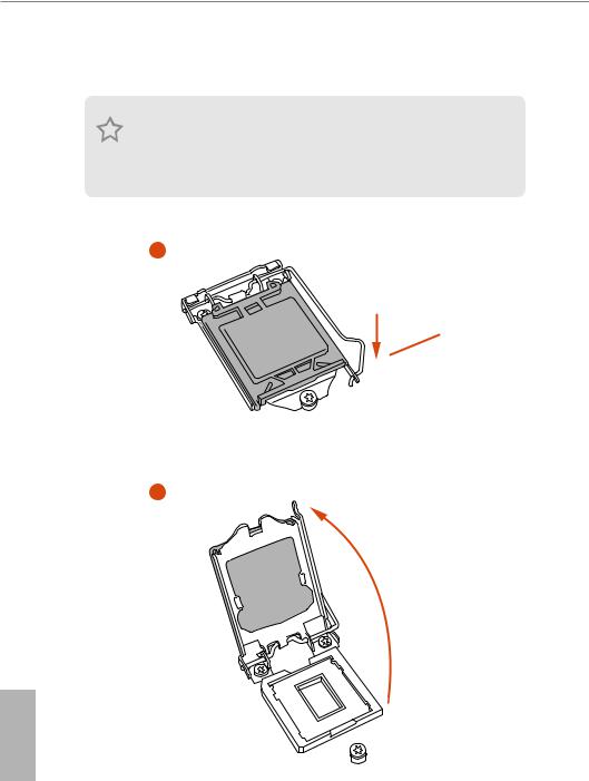
2.1Installing the CPU
1.Before you insert the 1151-Pin CPU into the socket, please check if the PnP cap is on the socket, if the CPU surface is unclean, or if there are any bent pins in the socket. Do not force to insert the CPU into the socket if above situation is found. Otherwise, the CPU will be seriously damaged.
2.Unplug all power cables before installing the CPU.
1
A
 B
B
2
English
12
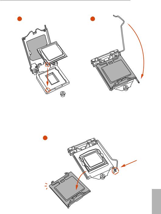
13

Please save and replace the cover if the processor is removed. The cover must be placed if you wish to return the motherboard for after service.
English
14
![]()
B250 Pro4
2.2 Installing the CPU Fan and Heatsink
N _FA PU C
English
15
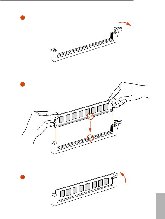
2.3 Installing Memory Modules (DIMM)
This motherboard provides four 288-pin DDR4 (Double Data Rate 4) DIMM slots, and supports Dual Channel Memory Technology.
1.For dual channel configuration, you always need to install identical (the same brand, speed, size and chip-type) DDR4 DIMM pairs.
2.It is unable to activate Dual Channel Memory Technology with only one or three memory module installed.
3.It is not allowed to install a DDR, DDR2 or DDR3 memory module into a DDR4 slot; otherwise, this motherboard and DIMM may be damaged.
Dual Channel Memory Configuration
|
Priority |
DDR4_A1 |
DDR4_A2 |
DDR4_B1 |
DDR4_B2 |
|
1 |
Populated |
Populated |
||
|
2 |
Populated |
Populated |
||
|
3 |
Populated |
Populated |
Populated |
Populated |
The DIMM only fits in one correct orientation. It will cause permanent damage to the motherboard and the DIMM if you force the DIMM into the slot at incorrect orientation.
English
16
17
2.4 Expansion Slots (PCI and PCI Express Slots)
There is I PCI slot and 5 PCI Express slots on the motherboard.
Before installing an expansion card, please make sure that the power supply is switched off or the power cord is unplugged. Please read the documentation of the expansion card and make necessary hardware settings for the card before you start the installation.
PCI slot:
The PCI1 is used to install expansion cards that have 32-bit PCI interface.
PCIe slots:
PCIE1 (PCIe 3.0 x1 slot) is used for PCI Express x1 lane width cards.
PCIE2 (PCIe 3.0 x16 slot) is used for PCI Express x16 lane width graphics cards. PCIE3 (PCIe 3.0 x1 slot) is used for PCI Express x1 lane width cards.
PCIE4 (PCIe 3.0 x16 slot) is used for PCI Express x4 lane width graphics cards. PCIE5 (PCIe 3.0 x1 slot) is used for PCI Express x1 lane width cards.
|
PCIE2 |
PCIE4 |
||
|
PCIe Slot Configurations |
x16 |
N/A |
|
|
Single Graphics Card |
|||
|
Two Graphics Cards in |
x16 |
x4 |
|
|
CrossFireXTM Mode |
|||
For a better thermal environment, please connect a chassis fan to the motherboard’s chassis fan connector (CHA_FAN1, CHA_FAN2 or CHA_FAN3) when using multiple graphics cards.
English
18
B250 Pro4
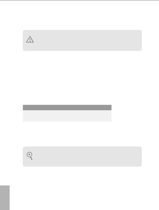
2.5 Jumpers Setup
The illustration shows how jumpers are setup. When the jumper cap is placed on the pins, the jumper is “Short”. If no jumper cap is placed on the pins, the jumper is “Open”. The illustration shows a 3-pin jumper whose pin1 and pin2 are “Short” when a jumper cap is placed on these 2 pins.
|
Clear CMOS Jumper |
|||
|
(CLRMOS1) |
Default |
Clear CMOS |
|
|
(see p.7, No. 20) |
|||
CLRMOS1 allows you to clear the data in CMOS. To clear and reset the system parameters to default setup, please turn off the computer and unplug the power cord from the power supply. After waiting for 15 seconds, use a jumper cap to short pin2 and pin3 on CLRMOS1 for 5 seconds. However, please do not clear the CMOS right after you update the BIOS. If you need to clear the CMOS when you just finish updating the BIOS, you must boot up the system first, and then shut it down before you do the clear-CMOS action. Please be noted that the password, date, time, and user default profile will be cleared only if the CMOS battery is removed.
If you clear the CMOS, the case open may be detected. Please adjust the BIOS option “Clear Status” to clear the record of previous chassis intrusion status.
English
19
2.6 Onboard Headers and Connectors
Onboard headers and connectors are NOT jumpers. Do NOT place jumper caps over these headers and connectors. Placing jumper caps over the headers and connectors will cause permanent damage to the motherboard.
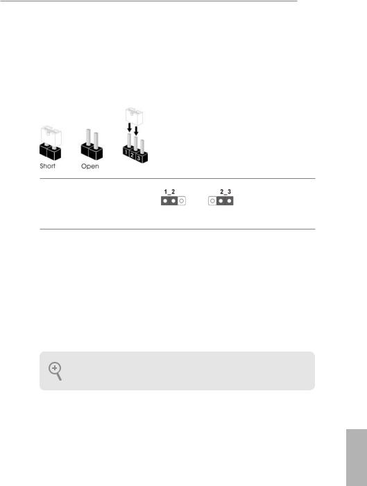
System Panel Header
(9-pin PANEL1)
(see p.7, No. 14)
PLED+ PLED-
PWRBTN#
GND
1
GND RESET#
GND HDLED-
HDLED+
Connect the power switch, reset switch and system status indicator on the chassis to this header according to the pin assignments below. Note the positive and negative pins before connecting the cables.
PWRBTN (Power Switch):
Connect to the power switch on the chassis front panel. You may configure the way to turn off your system using the power switch.
RESET (Reset Switch):
Connect to the reset switch on the chassis front panel. Press the reset switch to restart the computer if the computer freezes and fails to perform a normal restart.
PLED (System Power LED):
Connect to the power status indicator on the chassis front panel. The LED is on when the system is operating. The LED keeps blinking when the system is in S1/S3 sleep state. The LED is off when the system is in S4 sleep state or powered off (S5).
HDLED (Hard Drive Activity LED):
Connect to the hard drive activity LED on the chassis front panel. The LED is on when the hard drive is reading or writing data.
The front panel design may differ by chassis. A front panel module mainly consists of power switch, reset switch, power LED, hard drive activity LED, speaker and etc. When connecting your chassis front panel module to this header, make sure the wire assignments and the pin assignments are matched correctly.
English
20
 Loading…
View a manual of the Asrock B250 Pro4 below. All manuals on ManualsCat.com can be viewed completely free of charge. By using the ‘Select a language’ button, you can choose the language of the manual you want to view.
Page: 1
Version 1.1
Published November 2017
Copyright©2017 ASRock INC. All rights reserved.
Copyright Notice:
No part of this documentation may be reproduced, transcribed, transmitted, or
translated in any language, in any form or by any means, except duplication of
documentation by the purchaser for backup purpose, without written consent of
ASRock Inc.
Products and corporate names appearing in this documentation may or may not
be registered trademarks or copyrights of their respective companies, and are used
only for identification or explanation and to the owners’ benefit, without intent to
infringe.
Disclaimer:
Specifications and information contained in this documentation are furnished for
informational use only and subject to change without notice, and should not be
constructed as a commitment by ASRock. ASRock assumes no responsibility for
any errors or omissions that may appear in this documentation.
With respect to the contents of this documentation, ASRock does not provide
warranty of any kind, either expressed or implied, including but not limited to
the implied warranties or conditions of merchantability or fitness for a particular
purpose.
In no event shall ASRock, its directors, officers, employees, or agents be liable for
any indirect, special, incidental, or consequential damages (including damages for
loss of profits, loss of business, loss of data, interruption of business and the like),
even if ASRock has been advised of the possibility of such damages arising from any
defect or error in the documentation or product.
This device complies with Part 15 of the FCC Rules. Operation is subject to the following
two conditions:
(1) this device may not cause harmful interference, and
(2) this device must accept any interference received, including interference that
may cause undesired operation.
CALIFORNIA, USA ONLY
The Lithium battery adopted on this motherboard contains Perchlorate, a toxic substance
controlled in Perchlorate Best Management Practices (BMP) regulations passed by the
California Legislature. When you discard the Lithium battery in California, USA, please
follow the related regulations in advance.
“Perchlorate Material-special handling may apply, see www.dtsc.ca.gov/hazardouswaste/
perchlorate”
ASRock Website: http://www.asrock.com
Page: 2
AUSTRALIA ONLY
Our goods come with guarantees that cannot be excluded under the Australian Consumer
Law. You are entitled to a replacement or refund for a major failure and compensation for
any other reasonably foreseeable loss or damage caused by our goods. You are also entitled
to have the goods repaired or replaced if the goods fail to be of acceptable quality and the
failure does not amount to a major failure. If you require assistance please call ASRock Tel
: +886-2-28965588 ext.123 (Standard International call charges apply)
The terms HDMI™ and HDMI High-Definition Multimedia Interface, and the HDMI
logo are trademarks or registered trademarks of HDMI Licensing LLC in the United
States and other countries.
Page: 3
Contents
Chapter 1 Introduction 1
1.1 Package Contents 1
1.2 Specifications 2
1.3 Motherboard Layout 7
1.4 I/O Panel 9
Chapter 2 Installation 11
2.1 Installing the CPU 12
2.2 Installing the CPU Fan and Heatsink 15
2.3 Installing Memory Modules (DIMM) 16
2.4 Expansion Slots (PCI and PCI Express Slots) 18
2.5 Jumpers Setup 19
2.6 Onboard Headers and Connectors 20
2.7 CrossFireXTM
and Quad CrossFireXTM
Operation Guide 25
2.7.1 Installing Two CrossFireXTM
-Ready Graphics Cards 25
2.7.2 Driver Installation and Setup 27
2.8 M.2_SSD (NGFF) Module Installation Guide 28
Chapter 3 Software and Utilities Operation 31
3.1 Installing Drivers 31
3.2 A-Tuning 32
3.2.1 Installing A-Tuning 32
3.2.2 Using A-Tuning 32
3.3 ASRock Live Update & APP Shop 35
Page: 4
3.3.1 UI Overview 35
3.3.2 Apps 36
3.3.3 BIOS & Drivers 39
3.3.4 Setting 40
3.4 Enabling USB Ports for Windows® 7 Installation 41
Chapter 4 UEFI SETUP UTILITY 44
4.1 Introduction 44
4.2 EZ Mode 45
4.3 Advanced Mode 46
4.3.1 UEFI Menu Bar 46
4.3.2 Navigation Keys 47
4.4 Main Screen 48
4.5 OC Tweaker Screen 49
4.6 Advanced Screen 56
4.6.1 CPU Configuration 57
4.6.2 Chipset Configuration 59
4.6.3 Storage Configuration 62
4.6.4 Intel® Thunderbolt 63
4.6.5 Super IO Configuration 64
4.6.6 ACPI Configuration 65
4.6.7 USB Configuration 67
4.6.8 Trusted Computing 68
4.7 Tools 69
4.8 Hardware Health Event Monitoring Screen 72
Page: 5
4.9 Security Screen 75
4.10 Boot Screen 76
4.11 Exit Screen 79
Page: 6
1
English
B250 Pro4
Chapter 1 Introduction
Thank you for purchasing ASRock B250 Pro4 motherboard, a reliable motherboard
produced under ASRock’s consistently stringent quality control. It delivers excellent
performance with robust design conforming to ASRock’s commitment to quality
and endurance.
In this documentation, Chapter 1 and 2 contains the introduction of the
motherboard and step-by-step installation guides. Chapter 3 contains the operation
guide of the software and utilities. Chapter 4 contains the configuration guide of
the BIOS setup.
1.1 Package Contents
• ASRock B250 Pro4 Motherboard (ATX Form Factor)
• ASRock B250 Pro4 Quick Installation Guide
• ASRock B250 Pro4 Support CD
• 2 x Serial ATA (SATA) Data Cables (Optional)
• 1 x I/O Panel Shield
• 3 x Screws for M.2 Socket (Optional)
Because the motherboard specifications and the BIOS software might be updated, the
content of this documentation will be subject to change without notice. In case any
modifications of this documentation occur, the updated version will be available on
ASRock’s website without further notice. If you require technical support related to
this motherboard, please visit our website for specific information about the model
you are using. You may find the latest VGA cards and CPU support list on ASRock’s
website as well. ASRock website http://www.asrock.com.
Page: 7
2
English
1.2 Specifications
Platform • ATX Form Factor
CPU • Supports 7th
and 6th
Generation Intel® CoreTM
i7/i5/i3/
Pentium®/Celeron® Processors (Socket 1151)
• Digi Power design
• 8 Power Phase design
• Supports Intel® Turbo Boost 2.0 Technology
Chipset • Intel®
B250
Memory • Dual Channel DDR4 Memory Technology
• 4 x DDR4 DIMM Slots
• Supports DDR4 2400/2133 non-ECC, un-buffered memory*
* 7th
Gen Intel® CPU supports DDR4 up to 2400; 6th
Gen Intel®
CPU supports DDR4 up to 2133.
• Supports ECC UDIMM memory modules (operate in non-
ECC mode)
• Max. capacity of system memory: 64GB
• Supports Intel® Extreme Memory Profile (XMP) 2.0
• 15μ Gold Contact in DIMM Slots
Expansion
Slot
• 2 x PCI Express 3.0 x16 Slots (PCIE2: x16 mode; PCIE4: x4
mode)*
* Supports NVMe SSD as boot disks
* If PCIE5 slot or PCI slot is occupied, PCIE4 slot will run at x2
mode.
• 3 x PCI Express 3.0 x1 Slots (Flexible PCIe)
• 1 x PCI Slot
• Supports AMD Quad CrossFireXTM
and CrossFireXTM
• 1 x M.2 Socket (Key E), supports type 2230 WiFi/BT
module**
** M.2 Socket (Key E) and PCIE3 slot share lanes. If either one
of them is in use, the other one will be disabled.
Page: 8
3
English
B250 Pro4
Graphics • Intel® HD Graphics Built-in Visuals and the VGA outputs
can be supported only with processors which are GPU
integrated.
• Supports Intel® HD Graphics Built-in Visuals : Intel® Quick
Sync Video with AVC, MVC (S3D) and MPEG-2 Full
HW Encode1, Intel® InTruTM
3D, Intel® Clear Video HD
Technology, Intel® InsiderTM
, Intel® HD Graphics
• Gen9 LP, DX11.3, DX12
• HWAEncode/Decode: VP8, HEVC 8b, VP9, HEVC 10b (For
7th
Gen Intel® CPU)
• HWA Encode/Decode: VP8 , HEVC 8b; GPU/SWEncode/
Decode: VP9, HEVC 10b (For 6th
Gen Intel® CPU)
• Max. shared memory 1024MB
* The size of maximum shared memory may vary from different
operating systems.
• Three graphics output options: D-Sub, DVI-D and HDMI
• Supports Triple Monitor
• Supports HDMI with max. resolution up to 4K x 2K
(4096×2160) @ 24Hz / (3840×2160) @ 30Hz
• Supports DVI-D with max. resolution up to 1920×1200 @
60Hz
• Supports D-Sub with max. resolution up to 1920×1200 @
60Hz
• Supports Auto Lip Sync, Deep Color (12bpc), xvYCC and
HBR (High Bit Rate Audio) with HDMI Port
(Compliant HDMI monitor is required)
• Supports HDCP with DVI-D and HDMI Ports
• Supports Full HD 1080p Blu-ray (BD) playback with DVI-D
and HDMI Ports
Audio • 7.1 CH HD Audio with Content Protection (Realtek ALC892
Audio Codec)
* To configure 7.1 CH HD Audio, it is required to use an HD
front panel audio module and enable the multi-channel audio
feature through the audio driver.
• Premium Blu-ray Audio support
• Supports Surge Protection (ASRock Full Spike Protection)
• ELNA Audio Caps
Page: 9
4
English
LAN • Gigabit LAN 10/100/1000 Mb/s
• Giga PHY Intel® I219V
• Supports Wake-On-LAN
• Supports Lightning/ESD Protection (ASRock Full Spike
Protection)
• Supports Energy Efficient Ethernet 802.3az
• Supports PXE
Rear Panel
I/O
• 2 x Antenna Ports
• 1 x PS/2 Mouse/Keyboard Port
• 1 x D-Sub Port
• 1 x DVI-D Port
• 1 x HDMI Port
• 1 x USB 2.0 Port (Supports ESD Protection (ASRock Full
Spike Protection))
• 3 x USB 3.0 Type-A Ports (Supports ESD Protection (ASRock
Full Spike Protection))
• 1 x USB 3.0 Type-C Port (Supports ESD Protection (ASRock
Full Spike Protection))
• 1 x RJ-45 LAN Port with LED (ACT/LINK LED and SPEED
LED)
• HD Audio Jacks: Line in / Front Speaker / Microphone
Storage • 6 x SATA3 6.0 Gb/s Connectors, support NCQ, AHCI and
Hot Plug*
* If M2_1 is occupied by a SATA-type M.2 device, SATA3_5 will
be disabled.
* If M2_2 is occupied by a SATA-type M.2 device, SATA3_0 will
be disabled.
• 1 x Ultra M.2 Socket (M2_1), supports type
2230/2242/2260/2280 M.2 SATA3 6.0 Gb/s module and M.2
PCI Express module up to Gen3 x4 (32 Gb/s)**
• 1 x M.2 Socket (M2_2), supports type 2230/2242/2260/2280
M.2 SATA3 6.0 Gb/s module and M.2 PCI Express module
up to Gen3 x2 (16 Gb/s)**
** Supports Intel® OptaneTM
Technology
** Supports NVMe SSD as boot disks
** Supports ASRock U.2 Kit
Page: 10
5
English
B250 Pro4
Connector • 1 x COM Port Header
• 1 x TPM Header
• 1 x Chassis Intrusion Header
• 1 x Power LED and Speaker Header
• 1 x CPU Fan Connector (4-pin)
* The CPU Fan Connector supports the CPU fan of maximum
1A (12W) fan power.
• 2 x Chassis Fan Connectors (4-pin) (Smart Fan Speed Con-
trol)
• 1 x Chassis Optional/Water Pump Fan Connector (4-pin)
(Smart Fan Speed Control)
* The Chassis Optional/Water Pump Fan supports the water
cooler fan of maximum 1.5A (18W) fan power.
* CHA_FAN2 can auto detect if 3-pin or 4-pin fan is in use.
• 1 x 24 pin ATX Power Connector
• 1 x 8 pin 12V Power Connector
• 1 x Front Panel Audio Connector
• 1 x Thunderbolt AIC Connector (5-pin)
• 1 x Thunderbolt AIC Connector (10-pin)
* Only one Thunderbolt AIC Card is supported.
• 2 x USB 2.0 Headers (Support 4 USB 2.0 ports) (Supports
ESD Protection (ASRock Full Spike Protection))
• 1 x USB 3.0 Header (Supports 2 USB 3.0 ports) (Supports
ESD Protection (ASRock Full Spike Protection))
BIOS
Feature
• AMI UEFI Legal BIOS with multilingual GUI support
• ACPI 6.0 Compliant wake up events
• SMBIOS 2.7 Support
• CPU, GT_CPU, DRAM, VPP, PCH 1.0V, VCCIO, VCCST,
VCCSA, VCCPLL Voltage Multi-adjustment
Hardware
Monitor
• CPU / Chassis / Chassis Optional/Water Pump temperature
sensing
• CPU / Chassis / Chassis Optional/Water Pump Fan Tachom-
eter
• CPU / Chassis / Chassis Optional/Water Pump Quiet Fan
(Auto adjust chassis fan speed by CPU temperature)
Page: 11
6
English
• CPU / Chassis / Chassis Optional/Water Pump Fan multi-
speed control
• CASE OPEN detection
• Voltage monitoring: +12V, +5V, +3.3V, CPU Vcore, DRAM,
VPP, PCH 1.0V, VCCIO, VCCSA, VCCST
OS • Microsoft® Windows® 10 64-bit (For 7th
Gen Intel® CPU)
• Microsoft® Windows® 10 64-bit / 8.1 64-bit / 7 32-bit / 7 64-
bit (For 6th
Gen Intel® CPU)
* To install Windows® 7 OS, a modified installation disk with
xHCI drivers packed into the ISO file is required. Please refer to
page 41 for more detailed instructions.
* For the updated Windows® 10 driver, please visit ASRock’s
website for details: http://www.asrock.com
Certifica-
tions
• FCC, CE, WHQL, RCM, BSMI
• ErP/EuP ready (ErP/EuP ready power supply is required)
Please realize that there is a certain risk involved with overclocking, including
adjusting the setting in the BIOS, applying Untied Overclocking Technology, or using
third-party overclocking tools. Overclocking may affect your system’s stability, or
even cause damage to the components and devices of your system. It should be done
at your own risk and expense. We are not responsible for possible damage caused by
overclocking.
* For detailed product information, please visit our website: http://www.asrock.com
Page: 12
7
English
B250 Pro4
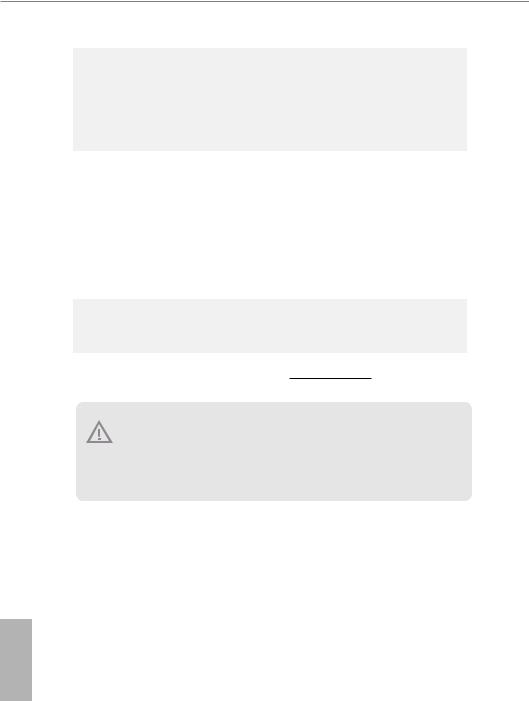
1.3 Motherboard Layout
Intel
B250
DDR4_A2
(64
bit,
288-pin
module)
DDR4_A1
(64
bit,
288-pin
module)
DDR4_B2
(64
bit,
288-pin
module)
DDR4_B1
(64
bit,
288-pin
module)
ATX12V1
USB
3.0
T:
USB_1
B:
USB_2
ATXPWR1
PCIE2
Top:
RJ-45
PCIE4
HDLED RESET
PLED PWRBTN
PANEL1
1
USB_5_6
1
1
SPK_PLED1
COM1
1
1
HD_AUDIO1
B250 Pro4
PCIE1
RoHS
10
8
9
13
14
15
16
17
18
19
22
1 4
3
20
Ultra M.2
PCIe Gen3 x4
PS2
Keyboard
/Mouse
CMOS
Battery
PCIE3
24
12
6
USB3_3_4
1
21
CHA_FAN2
11
USB_3_4
1
23
1
TPMS1
M2_1
Ct3
Ct2
Ct1 Ct4
7
Front USB 3.0
CHA_FAN3/W_PUMP
BIOS
ROM
Top:
LINE
IN
Center:
FRONT
Bottom:
MIC
IN
SATA_4
SATA_5
CHA_FAN1
CI1
1
25
26
PCI Express 3.0
SATA_2
SATA_3
SATA_0
SATA_1
CLRMOS1
1
CPU_FAN1
M2_3
NUT1
M2_2
Ct7
Ct6
Ct5 Ct8
T 1
B
1
HDMI1
DVI1
VGA1
USB
3.0
USB3_TC_1
T B2
1
5
2
PCIE5
PCI1
USB
3.0
USB_2
USB
2.0
USB_1
Page: 13
8
English
No. Description
1 ATX 12V Power Connector (ATX12V1)
2 Chassis Fan Connector (CHA_FAN2)
3 2 x 288-pin DDR4 DIMM Slots (DDR4_A1, DDR4_B1)
4 2 x 288-pin DDR4 DIMM Slots (DDR4_A2, DDR4_B2)
5 CPU Fan Connector (CPU_FAN1)
6 ATX Power Connector (ATXPWR1)
7 USB 3.0 Header (USB3_3_4)
8 SATA3 Connector (SATA3_5)
9 SATA3 Connector (SATA3_4)
10 SATA3 Connector (SATA3_3)
11 SATA3 Connector (SATA3_2)
12 SATA3 Connector (SATA3_1)
13 SATA3 Connector (SATA3_0)
14 System Panel Header (PANEL1)
15 Power LED and Speaker Header (SPK_PLED1)
16 Chassis Fan / Waterpump Fan Connector (CHA_FAN3/W_PUMP)
17 Chassis Fan Connector (CHA_FAN1)
18 USB 2.0 Header (USB_3_4)
19 USB 2.0 Header (USB_5_6)
20 Clear CMOS Jumper (CLRMOS1)
21 Chassis Intrusion Header (CI1)
22 TPM Header (TPMS1)
23 COM Port Header (COM1)
24 Front Panel Audio Header (HD_AUDIO1)
25 Thunderbolt AIC Connector (TB2)
26 Thunderbolt AIC Header (TB1)
Page: 14
9
English
B250 Pro4
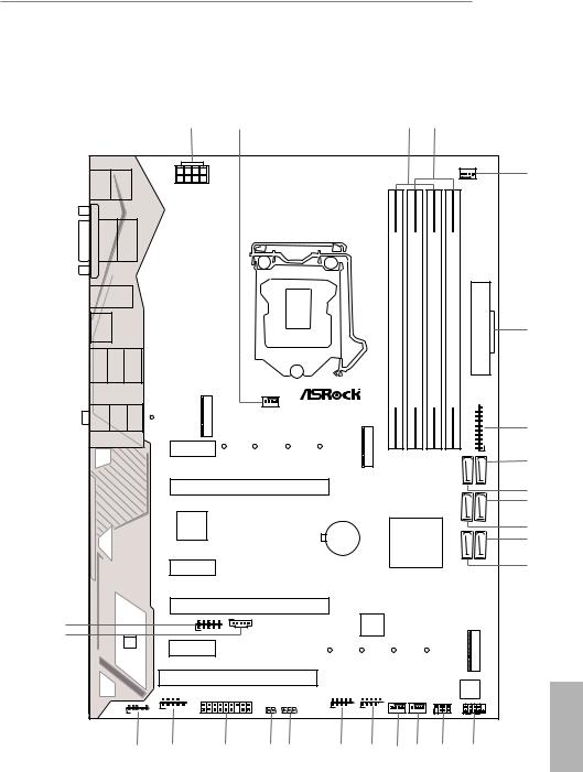
1.4 I/O Panel
1
12 8
9
11 7
6
5
2
10
4
3
13
No. Description No. Description
1 PS/2 Mouse/Keyboard Port 8 USB 3.0 Port (USB_2)
2 D-Sub Port 9 USB 3.0 Type-C Port (USB3_TC_1)
3 LAN RJ-45 Port* 10 HDMI Port
4 USB 2.0 Port (USB_1) 11 DVI-D Port
5 Line In (Light Blue)** 12 USB 3.0 Ports (USB3_1_2)
6 Front Speaker (Lime)** 13 Antenna Ports
7 Microphone (Pink)**
* There are two LEDs on each LAN port. Please refer to the table below for the LAN port LED indications.
Activity / Link LED Speed LED
Status Description Status Description
Off No Link Off 10Mbps connection
Blinking Data Activity Orange 100Mbps connection
On Link Green 1Gbps connection
ACT/LINK LED
SPEED LED
LAN Port
Page: 15
10
English
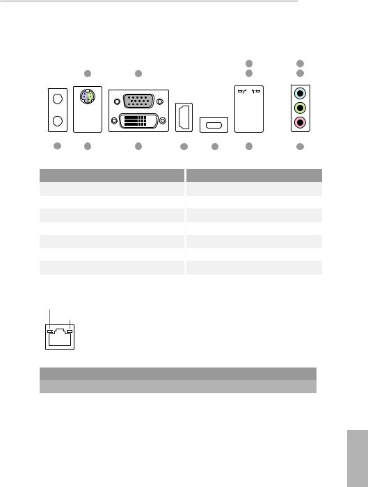
** To configure 7.1 CH HD Audio, it is required to use an HD front panel audio module and enable the multi-
channel audio feature through the audio driver.
Please set Speaker Configuration to “7.1 Speaker”in the Realtek HD Audio Manager.
Function of the Audio Ports in 7.1-channel Configuration:
Port Function
Light Blue (Rear panel) Rear Speaker Out
Lime (Rear panel) Front Speaker Out
Pink (Rear panel) Central /Subwoofer Speaker Out
Lime (Front panel) Side Speaker Out
Page: 16
11
English
B250 Pro4
This is an ATX form factor motherboard. Before you install the motherboard, study
the configuration of your chassis to ensure that the motherboard fits into it.
Pre-installation Precautions
Take note of the following precautions before you install motherboard components
or change any motherboard settings.
• Make sure to unplug the power cord before installing or removing the motherboard
components. Failure to do so may cause physical injuries and damages to motherboard
components.
• In order to avoid damage from static electricity to the motherboard’s components,
NEVER place your motherboard directly on a carpet. Also remember to use a grounded
wrist strap or touch a safety grounded object before you handle the components.
• Hold components by the edges and do not touch the ICs.
• Whenever you uninstall any components, place them on a grounded anti-static pad or
in the bag that comes with the components.
• When placing screws to secure the motherboard to the chassis, please do not over-
tighten the screws! Doing so may damage the motherboard.
Chapter 2 Installation
Page: 17
12
English
2.1 Installing the CPU
1. Before you insert the 1151-Pin CPU into the socket, please check if the PnP cap
is on the socket, if the CPU surface is unclean, or if there are any bent pins in the
socket. Do not force to insert the CPU into the socket if above situation is found.
Otherwise, the CPU will be seriously damaged.
2. Unplug all power cables before installing the CPU.
1
2
A
B
Page: 18
13
English
B250 Pro4
4
5
3
Page: 19
14
English
Please save and replace the cover if the processor is removed. The cover must be
placed if you wish to return the motherboard for after service.
Page: 20
15
English
B250 Pro4
2.2 Installing the CPU Fan and Heatsink
1 2
C
P
U
_
F
A
N
Page: 21
16
English
2.3 Installing Memory Modules (DIMM)
This motherboard provides four 288-pin DDR4 (Double Data Rate 4) DIMM slots,
and supports Dual Channel Memory Technology.
Dual Channel Memory Configuration
The DIMM only fits in one correct orientation. It will cause permanent damage to
the motherboard and the DIMM if you force the DIMM into the slot at incorrect
orientation.
Priority DDR4_A1 DDR4_A2 DDR4_B1 DDR4_B2
1 Populated Populated
2 Populated Populated
3 Populated Populated Populated Populated
1. For dual channel configuration, you always need to install identical (the same
brand, speed, size and chip-type) DDR4 DIMM pairs.
2. It is unable to activate Dual Channel Memory Technology with only one or three
memory module installed.
3. It is not allowed to install a DDR, DDR2 or DDR3 memory module into a DDR4
slot; otherwise, this motherboard and DIMM may be damaged.
Page: 22
17
English
B250 Pro4
1
2
3
Page: 23
18
English
2.4 Expansion Slots (PCI and PCI Express Slots)
There is I PCI slot and 5 PCI Express slots on the motherboard.
PCI slot:
The PCI1 is used to install expansion cards that have 32-bit PCI interface.
PCIe slots:
PCIE1 (PCIe 3.0 x1 slot) is used for PCI Express x1 lane width cards.
PCIE2 (PCIe 3.0 x16 slot) is used for PCI Express x16 lane width graphics cards.
PCIE3 (PCIe 3.0 x1 slot) is used for PCI Express x1 lane width cards.
PCIE4 (PCIe 3.0 x16 slot) is used for PCI Express x4 lane width graphics cards.
PCIE5 (PCIe 3.0 x1 slot) is used for PCI Express x1 lane width cards.
PCIe Slot Configurations
For a better thermal environment, please connect a chassis fan to the motherboard’s
chassis fan connector (CHA_FAN1, CHA_FAN2 or CHA_FAN3) when using mul-
tiple graphics cards.
Before installing an expansion card, please make sure that the power supply is
switched off or the power cord is unplugged. Please read the documentation of the
expansion card and make necessary hardware settings for the card before you start
the installation.
PCIE2 PCIE4
Single Graphics Card x16 N/A
Two Graphics Cards in
CrossFireXTM
Mode
x16 x4
Page: 24
19
English
B250 Pro4
2.5 Jumpers Setup
The illustration shows how jumpers are setup. When the jumper cap is placed on
the pins, the jumper is “Short”. If no jumper cap is placed on the pins, the jumper
is “Open”. The illustration shows a 3-pin jumper whose pin1 and pin2 are “Short”
when a jumper cap is placed on these 2 pins.
Clear CMOS Jumper
(CLRMOS1)
(see p.7, No. 20)
CLRMOS1 allows you to clear the data in CMOS. To clear and reset the system
parameters to default setup, please turn off the computer and unplug the power
cord from the power supply. After waiting for 15 seconds, use a jumper cap to
short pin2 and pin3 on CLRMOS1 for 5 seconds. However, please do not clear the
CMOS right after you update the BIOS. If you need to clear the CMOS when you
just finish updating the BIOS, you must boot up the system first, and then shut it
down before you do the clear-CMOS action. Please be noted that the password,
date, time, and user default profile will be cleared only if the CMOS battery is
removed.
Clear CMOS
Default
If you clear the CMOS, the case open may be detected. Please adjust the BIOS option
“Clear Status” to clear the record of previous chassis intrusion status.
Page: 25
20
English
2.6 Onboard Headers and Connectors
System Panel Header
(9-pin PANEL1)
(see p.7, No. 14)
Connect the power
switch, reset switch and
system status indicator on
the chassis to this header
according to the pin
assignments below. Note
the positive and negative
pins before connecting
the cables.
GND
RESET#
PWRBTN#
PLED-
PLED+
GND
HDLED-
HDLED+
1
GND
PWRBTN (Power Switch):
Connect to the power switch on the chassis front panel. You may configure the way to
turn off your system using the power switch.
RESET (Reset Switch):
Connect to the reset switch on the chassis front panel. Press the reset switch to restart
the computer if the computer freezes and fails to perform a normal restart.
PLED (System Power LED):
Connect to the power status indicator on the chassis front panel. The LED is on when
the system is operating. The LED keeps blinking when the system is in S1/S3 sleep
state. The LED is off when the system is in S4 sleep state or powered off (S5).
HDLED (Hard Drive Activity LED):
Connect to the hard drive activity LED on the chassis front panel. The LED is on
when the hard drive is reading or writing data.
The front panel design may differ by chassis. A front panel module mainly consists
of power switch, reset switch, power LED, hard drive activity LED, speaker and etc.
When connecting your chassis front panel module to this header, make sure the wire
assignments and the pin assignments are matched correctly.
Onboard headers and connectors are NOT jumpers. Do NOT place jumper caps over
these headers and connectors. Placing jumper caps over the headers and connectors
will cause permanent damage to the motherboard.
Page: 26
21
English
B250 Pro4
Power LED and Speaker
Header
(7-pin SPK_PLED1)
(see p.7, No. 15)
Please connect the
chassis power LED and
the chassis speaker to this
header.
Serial ATA3 Connectors
(SATA3_0:
see p.7, No. 13)
(SATA3_1:
see p.7, No. 12)
(SATA3_2:
see p.7, No. 11)
(SATA3_3:
see p.7, No. 10)
(SATA3_4:
see p.7, No. 9)
(SATA3_5:
see p.7, No. 
These six SATA3
connectors support SATA
data cables for internal
storage devices with up to
6.0 Gb/s data transfer rate.
* If M2_1 is occupied by a SATA-
type M.2 device, SATA3_5 will
be disabled.
* If M2_2 is occupied by a SATA-
type M.2 device, SATA3_0 will
be disabled.
USB 2.0 Headers
(9-pin USB_3_4)
(see p.7, No. 18)
(9-pin USB_5_6)
(see p.7, No. 19)
There are two USB
2.0 headers on this
motherboard. Each USB
2.0 header can support
two ports.
USB 3.0 Header
(19-pin USB3_3_4)
(see p.7, No. 7)
Besides four USB 3.0
ports on the I/O panel,
there is one header on this
motherboard. Each USB
3.0 header can support
two ports.
1
+5V
DUMMY
PLED+
PLED+
PLED-
DUMMY
SPEAKER
DUMMY
GND
GND
P+
P-
USB_PWR
P+
P-
USB_PWR
1
SATA_4
SATA_5
SATA_2
SATA_3
SATA_0
SATA_1
1
IntA_PB_D+
Dummy
IntA_PB_D-
GND
IntA_PB_SSTX+
GND
IntA_PB_SSTX-
IntA_PB_SSRX+
IntA_PB_SSRX-
Vbus
Vbus
Vbus
IntA_PA_SSRX-
IntA_PA_SSRX+
GND
IntA_PA_SSTX-
IntA_PA_SSTX+
GND
IntA_PA_D-
IntA_PA_D+
Page: 27
22
English
Front Panel Audio Header
(9-pin HD_AUDIO1)
(see p.7, No. 24)
This header is for
connecting audio devices
to the front audio panel.
Chassis Fan Connectors
(4-pin CHA_FAN1)
(see p.7, No. 17)
(4-pin CHA_FAN2)
(see p.7, No. 2)
Please connect fan cables
to the fan connectors and
match the black wire to
the ground pin.
Chassis Fan / Waterpump
Fan Connector
(4-pin CHA_FAN3/W_
PUMP)
(see p.7, No. 16)
Please connect fan cables
to the fan connectors and
match the black wire to
the ground pin.
J_SENSE
OUT2_L
1
MIC_RET
PRESENCE#
GND
OUT2_R
MIC2_R
MIC2_L
OUT_RET
1. High Definition Audio supports Jack Sensing, but the panel wire on the chassis
must support HDA to function correctly. Please follow the instructions in our
manual and chassis manual to install your system.
2. If you use an AC’97 audio panel, please install it to the front panel audio header by
the steps below:
A. Connect Mic_IN (MIC) to MIC2_L.
B. Connect Audio_R (RIN) to OUT2_R and Audio_L (LIN) to OUT2_L.
C. Connect Ground (GND) to Ground (GND).
D. MIC_RET and OUT_RET are for the HD audio panel only. You don’t need to
connect them for the AC’97 audio panel.
E. To activate the front mic, go to the “FrontMic” Tab in the Realtek Control panel
and adjust “Recording Volume”.
GND
FAN_VOLTAGE
CHA_FAN_SPEED
FAN_SPEED_CONTROL
4 3 2 1
GND
FAN_VOLTAGE
CHA_FAN_SPEED
FAN_SPEED_CONTROL
4 3 2 1
Page: 28
23
English
B250 Pro4
CPU Fan Connector
(4-pin CPU_FAN1)
(see p.7, No. 5)
This motherboard pro-
vides a 4-Pin CPU fan
(Quiet Fan) connector.
If you plan to connect a
3-Pin CPU fan, please
connect it to Pin 1-3.
ATX Power Connector
(24-pin ATXPWR1)
(see p.7, No. 6)
This motherboard pro-
vides a 24-pin ATX power
connector. To use a 20-pin
ATX power supply, please
plug it along Pin 1 and Pin
13.
ATX 12V Power
Connector
(8-pin ATX12V1)
(see p.7, No. 1)
This motherboard pro-
vides an 8-pin ATX 12V
power connector. To use a
4-pin ATX power supply,
please plug it along Pin 1
and Pin 5.
Serial Port Header
(9-pin COM1)
(see p.7, No. 23)
This COM1 header
supports a serial port
module.
Chassis Intrusion Header
(2-pin CI1)
(see p.7, No. 21)
This motherboard supports
CASE OPEN detection feature
that detects if the chassis cove
has been removed. This feature
requires a chassis with chassis
intrusion detection design.
CCTS#1
RRTS#1
DDSR#1
DDTR#1
RRXD1
GND
TTXD1
DDCD#1
1
RRI#1
GND
FAN_VOLTAGE
CPU_FAN_SPEED
FAN_SPEED_CONTROL
1 2 3 4
12
1
24
13
5
1
8
4
1
Signal
GND
Page: 29
24
English
TPM Header
(17-pin TPMS1)
(see p.7, No. 22)
This connector supports Trusted
Platform Module (TPM) system,
which can securely store keys,
digital certificates, passwords,
and data. A TPM system also
helps enhance network security,
protects digital identities, and
ensures platform integrity.
Thunderbolt AIC
Connector
(5-pin TB2)
(see p.7, No. 23)
1 Please connect a Thunderbolt™
add-in card (AIC) to this
connector via the GPIO cable.
Thunderbolt AIC Header
(10-pin TB1)
(see p.7, No. 26)
SLP_S5#
GND
1
SLP_S3#
CIO Plug Event
Force Power
I2C_MASTER_DATA
PA_DPSRC_HPD
I2C_MASTER_CLK
PA_PPS_INT#
GND
Please connect a Thunderbolt™
add-in card (AIC) to this
connector via the GPIO cable.
1
GND
SMB_DATA_MAIN
LAD2
LAD1
GND
S_PWRDWN#
SERIRQ#
GND
PCICLK
PCIRST#
LAD3
+3V
LAD0
+3VSB
GND
FRAME
SMB_CLK_MAIN
Page: 30
25
English
B250 Pro4
2.7 CrossFireXTM
and Quad CrossFireXTM
Operation Guide
This motherboard supports CrossFireXTM
and Quad CrossFireXTM
that allows you
to install up to three identical PCI Express x16 graphics cards.
2.7.1 Installing Two CrossFireXTM
-Ready Graphics Cards
Step 1
Insert one graphics card into PCIE2 slot
and the other graphics card to PCIE4 slot.
Make sure that the cards are properly
seated on the slots.
Step 2
Connect two graphics cards by installing
a CrossFire Bridge on the CrossFire Bridge
Interconnects on the top of the graphics
cards. (The CrossFire Bridge is provided
with the graphics card you purchase, not
bundled with this motherboard. Please
refer to your graphics card vendor for
details.)
1. You should only use identical CrossFireXTM
-ready graphics cards that are AMD
certified.
2. Make sure that your graphics card driver supports AMD CrossFireXTM
technology.
Download the drivers from the AMD’s website: www.amd.com
3. Make sure that your power supply unit (PSU) can provide at least the minimum
power your system requires. It is recommended to use a AMD certified PSU. Please
refer to the AMD’s website for details.
4. If you pair a 12-pipe CrossFireXTM
Edition card with a 16-pipe card, both cards will
operate as 12-pipe cards while in CrossFireXTM
mode.
5. Different CrossFireXTM
cards may require different methods to enable CrossFi-
reXTM
. Please refer to AMD graphics card manuals for detailed installation guide.
CrossFire Bridge
Page: 31
26
English
Step 3
Connect a VGA cable or a DVI cable to the
monitor connector or the DVI connec-
tor of the graphics card that is inserted to
PCIE2 slot.
Page: 32
27
English
B250 Pro4
Step 1
Power on your computer and boot into OS.
Step 2
Remove the AMD drivers if you have any VGA drivers installed in your system.
Step 3
Install the required drivers and CATALYST Control Center then restart your
computer. Please check AMD’s website for details.
2.7.2 Driver Installation and Setup
Step 4
Double-click the AMD Catalyst Control
Center icon in the Windows®
system tray.
Step 5
In the left pane, click Performance and
then AMD CrossFireXTM
. Then select
Enable AMD CrossFireX and click Apply.
Select the GPU number according to your
graphics card and click Apply.
AMD Catalyst Control Center
The Catalyst Uninstaller is an optional download. We recommend using this utility
to uninstall any previously installed Catalyst drivers prior to installation. Please
check AMD’s website for AMD driver updates.
Page: 33
28
English
2.8 M.2_SSD (NGFF) Module Installation Guide
The M.2, also known as the Next Generation Form Factor (NGFF), is a small size and
versatile card edge connector that aims to replace mPCIe and mSATA. The Ultra M.2
Socket (M2_1) supports SATA3 6.0 Gb/s module and M.2 PCI Express module up to Gen3
x4 (32 Gb/s). The M.2 Sockets (M2_2) supports SATA3 6.0 Gb/s module and M.2 PCI
Express module up to Gen3 x2 (16 Gb/s).
* If M2_1 is occupied by a SATA-type M.2 device, SATA3_5 will be disabled.
* If M2_2 is occupied by a SATA-type M.2 device, SATA3_0 will be disabled.
Installing the M.2_SSD (NGFF) Module
Step 1
Prepare a M.2_SSD (NGFF) module
and the screw.
3
2
4
5
B
C
D
E A
1
Step 2
Depending on the PCB type and
length of your M.2_SSD (NGFF)
module, find the corresponding nut
location to be used.
No. 1 2 3 4
Nut Location A B C D
PCB Length 3cm 4.2cm 6cm 8cm
Module Type Type2230 Type 2242 Type2260 Type 2280
Page: 34
29
English
B250 Pro4
B
C
D
E A
Step 3
Move the standoff based on the
module type and length.
The standoff is placed at the nut
location D by default. Skip Step 3
and 4 and go straight to Step 5 if you
are going to use the default nut.
Otherwise, release the standoff by
hand.
B
C
D
E A
Step 4
Peel off the yellow protective film on
the nut to be used. Hand tighten the
standoff into the desired nut location
on the motherboard.
B
C A
A
B
C
D
E
Step 5
Align and gently insert the M.2
(NGFF) SSD module into the M.2
slot. Please be aware that the M.2
(NGFF) SSD module only fits in one
orientation.
NUT1
NUT2
D
E
Step 6
Tighten the screw with a screwdriver
to secure the module into place.
Please do not overtighten the screw
as this might damage the module.
Page: 35
30
English
M.2_SSD (NGFF) Module Support List
For the latest updates of M.2_SSD (NFGG) module support list, please visit our website for
details: http://www.asrock.com
Vendor Size Interface Length P/N
ADATA 128GB SATA3 2280 AXNS381E-128GM-B
ADATA 256GB SATA3 2280 AXNS381E-256GM-B
ADATA 32GB SATA3 2230 AXNS330E-32GM-B
Crucial 120GB SATA3 2280 CT120M500SSD4
Crucial 240GB SATA3 2280 CT240M500SSD4
Intel 80GB SATA3 2280 Intel SSDSCKGW080A401/80G
Intel 256GB PCIe3 x4 2280 SSDPEKKF256G7
Intel 512GB PCIe3 x4 2280 SSDPEKKF512G7
Kingston 120GB SATA3 2280 SM2280S3
Kingston 480GB PCIe2 x4 2280 SH2280S3/480G
OCZ 512GB PCIe3 x4 2280 RVD400 -M2280-512G (NVME)
Plextor 128GB PCIe3 x4 2280 PX-128M8PeG
Plextor 1TB PCIe3 x4 2280 PX-1TM8PeG
Plextor 256GB PCIe3 x4 2280 PX-256M8PeG
Plextor 256GB PCIe 2280 PX-G256M6e
Plextor 512GB PCIe3 x4 2280 PX-512M8PeG
Plextor 512GB PCIe 2280 PX-G512M6e
Samsung 256GB PCIe3 x4 2280 SM951 (MZHPV256HDGL)
Samsung 256GB PCIe3 x4 2280 SM951 (NVME)
Samsung 512GB PCIe3 x4 2280 SM951 (MZHPV512HDGL)
Samsung 512GB PCIe3 x4 2280 SM951 (NVME)
Samsung 512GB PCIe x4 2280 XP941-512G (MZHPU512HCGL)
SanDisk 128GB PCIe 2260 SD6PP4M-128G
SanDisk 256GB PCIe 2260 SD6PP4M-256G
Team 128GB SATA3 2242 TM4PS4128GMC105
Team 128GB SATA3 2280 TM8PS4128GMC105
Team 256GB SATA3 2280 TM8PS4256GMC105
Team 256GB SATA3 2242 TM4PS4256GMC105
Transcend 256GB SATA3 2242 TS256GMTS400
Transcend 512GB SATA3 2260 TS512GMTS600
Transcend 512GB SATA3 2280 TS512GMTS800
V-Color 120GB SATA3 2280 VLM100-120G-2280B-RD
V-Color 240GB SATA3 2280 VLM100-240G-2280B-RD
V-Color 240GB SATA3 2280 VSM100-240G-2280
Page: 36
31
English
B250 Pro4
Chapter 3 Software and Utilities Operation
3.1 Installing Drivers
The Support CD that comes with the motherboard contains necessary drivers and
useful utilities that enhance the motherboard’s features.
Running The Support CD
To begin using the support CD, insert the CD into your CD-ROM drive. The CD
automatically displays the Main Menu if “AUTORUN” is enabled in your computer.
If the Main Menu does not appear automatically, locate and double click on the file
“ASRSETUP.EXE” in the Support CD to display the menu.
Drivers Menu
The drivers compatible to your system will be auto-detected and listed on the
support CD driver page. Please click Install All or follow the order from top to
bottom to install those required drivers. Therefore, the drivers you install can work
properly.
Utilities Menu
The Utilities Menu shows the application software that the motherboard supports.
Click on a specific item then follow the installation wizard to install it.
To improve Windows 7 compatibility, please download and install the following hot
fix provided by Microsoft.
“KB2720599”: http://support.microsoft.com/kb/2720599/en-us
Page: 37
32
English
3.2 A-Tuning
A-Tuning is ASRock’s multi purpose software suite with a new interface, more new
features and improved utilities.
3.2.1 Installing A-Tuning
A-Tuning can be downloaded from ASRock Live Update & APP Shop. After the
installation, you will find the icon “A-Tuning“ on your desktop. Double-click the
“A-Tuning“ icon, A-Tuning main menu will pop up.
3.2.2 Using A-Tuning
There are six sections in A-Tuning main menu: Operation Mode, OC Tweaker,
System Info, FAN-Tastic Tuning and Settings.
Operation Mode
Choose an operation mode for your computer.
Page: 38
33
English
B250 Pro4
OC Tweaker
Configurations for overclocking the system.
System Info
View information about the system.
*The System Browser tab may not appear for certain models.
Page: 39
34
English
FAN-Tastic Tuning
Configure up to five different fan speeds using the graph. The fans will automatically shift
to the next speed level when the assigned temperature is met.
Settings
Configure ASRock A-Tuning. Click to select «Auto run at Windows Startup» if you
want A-Tuning to be launched when you start up the Windows operating system.
Page: 40
35
English
B250 Pro4
3.3 ASRock Live Update & APP Shop
The ASRock Live Update & APP Shop is an online store for purchasing and
downloading software applications for your ASRock computer. You can quickly
and easily install various apps and support utilities. With ASRock APP Shop, you
can optimize your system and keep your motherboard up to date simply with a few
clicks.
Double-click on your desktop to access ASRock Live Update & APP Shop
utility.
*You need to be connected to the Internet to download apps from the ASRock Live Update & APP Shop.
3.3.1 UI Overview
Category Panel: The category panel contains several category tabs or buttons that
when selected the information panel below displays the relative information.
Information Panel: The information panel in the center displays data about the
currently selected category and allows users to perform job-related tasks.
Hot News: The hot news section displays the various latest news. Click on the image
to visit the website of the selected news and know more.
Information Panel
Hot News
Category Panel
Page: 41
36
English
3.3.2 Apps
When the «Apps» tab is selected, you will see all the available apps on screen for you
to download.
Installing an App
Step 1
Find the app you want to install.
The most recommended app appears on the left side of the screen. The other various
apps are shown on the right. Please scroll up and down to see more apps listed.
You can check the price of the app and whether you have already intalled it or not.
— The red icon displays the price or «Free» if the app is free of charge.
— The green «Installed» icon means the app is installed on your computer.
Step 2
Click on the app icon to see more details about the selected app.
Page: 42
37
English
B250 Pro4
Step 3
If you want to install the app, click on the red icon to start downloading.
Step 4
When installation completes, you can find the green «Installed» icon appears on the
upper right corner.
To uninstall it, simply click on the trash can icon .
*The trash icon may not appear for certain apps.
Page: 43
38
English
Upgrading an App
You can only upgrade the apps you have already installed. When there is an
available new version for your app, you will find the mark of «New Version»
appears below the installed app icon.
Step 1
Click on the app icon to see more details.
Step 2
Click on the yellow icon to start upgrading.
Page: 44
39
English
B250 Pro4
3.3.3 BIOS & Drivers
Installing BIOS or Drivers
When the «BIOS & Drivers» tab is selected, you will see a list of recommended or
critical updates for the BIOS or drivers. Please update them all soon.
Step 1
Please check the item information before update. Click on to see more details.
Step 2
Click to select one or more items you want to update.
Step 3
Click Update to start the update process.
Page: 45
40
English
3.3.4 Setting
In the «Setting» page, you can change the language, select the server location, and
determine if you want to automatically run the ASRock Live Update & APP Shop
on Windows startup.
Page: 46
41
English
B250 Pro4
3.4 Enabling USB Ports for Windows® 7 Installation
Intel® new processors have removed removed their support for the Enhanced Host
Controller Interface (EHCI – USB2.0) and only kept the eXtensible Host Controller
Interface (XHCI – USB3.0). Due to that fact that XHCI is not included in the
Windows 7 inbox drivers, users may find it difficult to install Windows 7 operating
system because the USB ports on their motherboard won’t work. In order for the
USB ports to function properly, please create a Windows® 7 installation disk with
the Intel® USB 3.0 eXtensible Host Controller (xHCI) drivers packed into the ISO
file.
Requirements
• A Windows® 7 installation disk or USB drive
• USB 3.0 drivers (included in the ASRock Support CD or website)
• A Windows® PC
• Win7 USB Patcher (included in the ASRock Support CD or website)
Scenarios
You have an ODD and PS/2 ports:
If there is an optical disc drive, PS/2 ports and PS/2 Keyboard or mouse on your computer,
you can skip the instructions below and go ahead to install Windows® 7 OS.
You’ve got nothing:
If you do not have an optical disc drive, please find another computer and follow the
instructions below to create a new ISO file with the “Win7 USB Patcher”. Then use the new
patched Windows® 7 installation USB drive to install Windows® 7 OS.
Page: 47
42
English
Instructions
Step 1
Insert the Windows® 7 installation disk or USB drive to your system.
Step 2
Extract the tool (Win7 USB Patcher) and launch it.
Step 3
Select the “Win7 Folder” from Step1 by clicking the red circle as shown as the picture
below.
Step 4
Select the “USB Driver Folder” by clicking the red circle as shown as the picture below.
If you are using ASRock’s Support CD for the USB 3.0 driver, please select your CD-ROM.
Page: 48
43
English
B250 Pro4
Step 5
Select where to save the ISO file by pressing the red circle as shown as the picture below.
Step 6
If you want to burn the patched image to a CD, please check “Burn Image” and select “Target
Device to Burn”. If not, the patched ISO image will be exported to the destination selected
in Step5. Then Press “Start” to proceed.
Step 7
Now you are able to install Windows® 7 on processors with the new burned CD. Or please
use the patched ISO image to make an OS USB drive to install the OS.
Page: 49
44
English
Chapter 4 UEFI SETUP UTILITY
4.1 Introduction
This section explains how to use the UEFI SETUP UTILITY to configure your
system. You may run the UEFI SETUP UTILITY by pressing <F2> or <Del> right
after you power on the computer, otherwise, the Power-On-Self-Test (POST) will
continue with its test routines. If you wish to enter the UEFI SETUP UTILITY after
POST, restart the system by pressing <Ctl> + <Alt> + <Delete>, or by pressing the
reset button on the system chassis. You may also restart by turning the system off
and then back on.
Because the UEFI software is constantly being updated, the following UEFI setup screens
and descriptions are for reference purpose only, and they may not exactly match what you
see on your screen.
Page: 50
45
English
B250 Pro4
4.2 EZ Mode
The EZ Mode screen appears when you enter the BIOS setup program by default. EZ
mode is a dashboard which contains multiple readings of the system’s current status.
You can check the most crucial information of your system, such as CPU speed,
DRAM frequency, SATA information, fan speed, etc.
Press <F6> or click the «Advanced Mode» button at the upper right corner of the
screen to switch to «Advanced Mode» for more options.
No. Function
1 Help
2 Load UEFI Defaults
3 Save Changes and Exit
4 Discard Changes
5 Change Language
6 Switch to Advanced Mode
Инструкцию для ASRock B250M Pro4 на русском языке, в формате pdf можно скачать с нашего сайта. Наш каталог предоставляем Вам инструкцию производителя фирмы ASRock, которая была взята из открытых источников. Ознакомившись с руководством по эксплуатации от ASRock, Вы на все 100% и правильно сможете воспользоваться всеми функциями устройства.
Для сохранения инструкции «Материнская плата ASRock B250M Pro4» на русском языке на вашем компьютере либо телефоне, нажмите кнопку «Скачать инструкцию». Если активна кнопка «Инструкция онлайн», то Вы можете просмотреть документ (manual), в своём браузере онлайн.
Если у Вас нет возможности скачать инструкцию по эксплуатации либо просмотреть её, Вы можете поделиться ссылкой на эту страницу в социальных сетях и при удобном моменте скачать инструкцию. Либо добавьте эту страницу в закладки Вашего браузера, нажав кнопку «Добавить страницу в закладки браузера».