-
Bookmarks
-
ENGLISH, page 1
-
РУССКИЙ, страница 99
-
FRANÇAIS, page 60
-
ESPAÑOL, página 86
-
DEUTSCH, seite 47
-
ITALIANO, pagina 73
-
PORTUGUÊS, página 112
-
POLSKI, strona 125
-
汉语, 第 164 页
-
日本語, 151ページ
-
조선말/한국어, 138페이지
-
漢語, 第 178 页
Quick Links
Version 1.0
Published May 2020
Copyright©2020 ASRock INC. All rights reserved.
Copyright Notice:
No part of this documentation may be reproduced, transcribed, transmitted, or
translated in any language, in any form or by any means, except duplication of
documentation by the purchaser for backup purpose, without written consent of
ASRock Inc.
Products and corporate names appearing in this documentation may or may not
be registered trademarks or copyrights of their respective companies, and are used
only for identification or explanation and to the owners’ benefit, without intent to
infringe.
Disclaimer:
Specifications and information contained in this documentation are furnished for
informational use only and subject to change without notice, and should not be
constructed as a commitment by ASRock. ASRock assumes no responsibility for
any errors or omissions that may appear in this documentation.
With respect to the contents of this documentation, ASRock does not provide
warranty of any kind, either expressed or implied, including but not limited to
the implied warranties or conditions of merchantability or fitness for a particular
purpose.
In no event shall ASRock, its directors, officers, employees, or agents be liable for
any indirect, special, incidental, or consequential damages (including damages for
loss of profits, loss of business, loss of data, interruption of business and the like),
even if ASRock has been advised of the possibility of such damages arising from any
defect or error in the documentation or product.
This device complies with Part 15 of the FCC Rules. Operation is subject to the following
two conditions:
(1) this device may not cause harmful interference, and
(2) this device must accept any interference received, including interference that
may cause undesired operation.
CALIFORNIA, USA ONLY
The Lithium battery adopted on this motherboard contains Perchlorate, a toxic substance
controlled in Perchlorate Best Management Practices (BMP) regulations passed by the
California Legislature. When you discard the Lithium battery in California, USA, please
follow the related regulations in advance.
«Perchlorate Material-special handling may apply, see www.dtsc.ca.gov/hazardouswaste/
perchlorate»
ASRock Website: http://www.asrock.com
Summary of Contents for ASROCK B550 PRO4
Посмотреть инструкция для Asrock B550 Pro4 бесплатно. Руководство относится к категории материнские платы, 1 человек(а) дали ему среднюю оценку 7.5. Руководство доступно на следующих языках: английский. У вас есть вопрос о Asrock B550 Pro4 или вам нужна помощь? Задайте свой вопрос здесь
Не можете найти ответ на свой вопрос в руководстве? Вы можете найти ответ на свой вопрос ниже, в разделе часто задаваемых вопросов о Asrock B550 Pro4.
Какой вес Asrock B550 Pro4?
Какая высота Asrock B550 Pro4?
Какая ширина Asrock B550 Pro4?
Какая толщина Asrock B550 Pro4?
Инструкция Asrock B550 Pro4 доступно в русский?
Не нашли свой вопрос? Задайте свой вопрос здесь
![]()
Руководство по установке AMD RAID
Руководство по установке AMD BIOS RAID
Руководство по установке AMD BIOS RAID — это инструкция по настройке функций RAID с помощью встроенной утилиты FastBuild BIOS в среде BIOS. После создания дискеты с драйверами SATA нажмите или же чтобы войти в настройки BIOS, чтобы установить параметр в режим RAID, следуя подробным инструкциям «Руководства пользователя» на нашем вспомогательном компакт-диске, затем вы можете начать использовать встроенную утилиту RAID Option ROM для настройки RAID.
Введение в RAID
Термин «RAID» означает «избыточный массив независимых дисков», который представляет собой метод объединения двух или более жестких дисков в один логический блок. Для оптимальной производительности устанавливайте одинаковые диски одной модели и емкости при создании набора RAID.
RAID 0 (разделение данных)
RAID 0 называется чередованием данных, которое оптимизирует два идентичных жестких диска для чтения и записи данных в параллельных чередующихся стеках. Это улучшит доступ к данным и их хранение, поскольку удвоит скорость передачи данных по сравнению с одним диском, в то время как два жестких диска будут выполнять ту же работу, что и один диск, но с постоянной скоростью передачи данных.
 ПРЕДУПРЕЖДЕНИЕ!! Хотя функция RAID 0 может повысить производительность доступа, она не обеспечивает отказоустойчивости. Горячее подключение любых жестких дисков диска RAID 0 приведет к повреждению или потере данных.
RAID 1 (зеркалирование данных)
RAID 1 называется зеркалированием данных, которое копирует и поддерживает идентичный образ данных с одного диска на второй диск. Он обеспечивает защиту данных и повышает отказоустойчивость всей системы, поскольку программное обеспечение управления дисковым массивом направляет все приложения на уцелевший диск, поскольку он содержит полную копию данных на другом диске в случае отказа одного диска.
 RAID 5 (чередование блоков с распределенной четностью)
RAID 5 чередует данные и распределяет информацию о четности по физическим дискам вместе с блоками данных. Такая организация повышает производительность за счет одновременного доступа к нескольким физическим дискам для каждой операции, а также повышает отказоустойчивость за счет предоставления данных четности. В случае сбоя физического диска данные могут быть пересчитаны системой RAID на основе оставшихся данных и информации о четности. RAID 5 эффективно использует жесткие диски и является наиболее универсальным уровнем RAID. Это хорошо работает для file, база данных, приложение и web сервера.

RAID 10 (полосное зеркалирование)
Диски RAID 0 можно зеркально отразить с помощью методов RAID 1, в результате чего получится решение RAID 10 с повышенной производительностью и отказоустойчивостью. Контроллер сочетает в себе производительность чередования данных (RAID 0) и отказоустойчивость зеркалирования дисков (RAID 1). Данные распределяются по нескольким дискам и дублируются на другом наборе дисков.
 Меры предосторожности при конфигурациях RAID
 Меры предосторожности при конфигурациях RAID
- Пожалуйста, используйте два новых диска, если вы создаете массив RAID 0 (чередование) для повышения производительности. Рекомендуется использовать два диска SATA одинакового размера. Если вы используете два диска разного размера, жесткий диск меньшей емкости будет базовым объемом хранилища для каждого диска. Для бывшегоample, если один жесткий диск имеет емкость 80 ГБ, а другой жесткий диск имеет емкость 60 ГБ, максимальная емкость хранилища для диска емкостью 80 ГБ становится 60 ГБ, а общая емкость хранилища для этого набора RAID 0 составляет 120 ГБ.
- Вы можете использовать два новых диска или использовать существующий диск и новый диск для создания массива RAID 1 (зеркалирование) для защиты данных (новый диск должен быть того же размера или больше, чем существующий диск). Если вы используете два диска разного размера, жесткий диск меньшей емкости будет базовым объемом хранилища. Для бывшегоample, если один жесткий диск имеет емкость хранения 80 ГБ, а другой жесткий диск — 60 ГБ, максимальная емкость хранилища для набора RAID 1 составляет 60 ГБ.
- Перед настройкой нового RAID-массива проверьте состояние своих жестких дисков.
ПРЕДУПРЕЖДЕНИЕ!! Прежде чем создавать функции RAID, сделайте резервную копию данных. В процессе создания RAID система спросит, хотите ли вы «Очистить данные диска» или нет. Рекомендуется выбрать «Да», и тогда ваше будущее здание данных будет работать в чистой среде.
Конфигурация UEFI RAID
Настройте массив RAID с помощью утилиты настройки UEFI.
ШАГ 1. Настройте UEFI и создайте массив RAID
A. Во время загрузки системы нажмите или же ключ для входа в утилиту настройки UEFI.
B. Перейдите к расширенной конфигурации хранилища.
C. Установите для параметра «Режим SATA» значение .
Д. Нажмите сохранить, чтобы выйти.
E. (Этот шаг предназначен только для NVMe RAID на чипсетах X399/X570):
Перейдите на AdvancedAMD PBS и установите «Режим NVMe RAID» на . Затем нажмите сохранить, чтобы выйти.

F. Перейдите в BootCSM и установите для параметра «Политика запуска хранилища OpROM» значение .
 or
or
Перейдите в BootCSM и установите для параметра «Запуск CSM» значение .

Ж. Нажмите для сохранения изменений и выхода, а затем снова войдите в программу настройки BIOS.
H. После сохранения ранее измененных настроек через F10 и перезагрузки системы становится доступным подменю «RAIDXpert2 Configuration Utility».

I. Перейдите в раздел «Дополнительно» → «Утилита настройки RAIDXpert2» → «Управление массивами», а затем удалите существующие дисковые массивы перед созданием нового массива.
Даже если вы еще не настроили какой-либо RAID-массив, вам, возможно, придется сначала использовать «Удалить массив».


J. Перейдите в раздел «Дополнительно» → «Утилита настройки RAIDXpert2» → «Управление массивом» → «Создать массив».

Выберите «Уровень RAID», а затем «Выбрать физические диски».

Измените «Выбрать тип носителя» на «SSD» или оставьте «ОБА».

Выберите Проверить всеПрименить изменения

Выберите «Создать массив».

К. Нажмите сохранить, чтобы выйти.
ШАГ 2.1. Скопируйте драйвер RAID на USB-накопитель
Вы можете выбрать ШАГ 2.1 или ШАГ 2.2, чтобы завершить настройку.
A. Пожалуйста, установите DVD-ROM.
B. Во время загрузки системы нажмите или же ключ для входа в утилиту настройки UEFI.
C. Подключите USB-накопитель к одному из USB-портов.
D. Вставьте компакт-диск поддержки в дисковод DVD-ROM.
E. Перейдите к инструменту Easy RAID Installer.
F. Следуйте инструкциям, чтобы завершить процесс копирования драйвера.
ШАГ 2.2: Загрузите драйвер с сайта ASRock webсайт
О. Пожалуйста, загрузите драйвер SATA Floppy Imaged с веб-сайта ASRock. webсайт и разархивируйте file на USB-накопитель.
ШАГ 3: Установка Windows
Вставьте USB-накопитель с установкой Windows 10 fileс. Затем перезапустите систему. Пока эта система загружается, пожалуйста
нажмите F11, чтобы открыть меню загрузки, показанное на этом рисунке.
USB-накопитель должен быть указан как устройство UEFI. Пожалуйста, выберите это для загрузки.
Если в этот момент система перезагрузится, снова откройте меню загрузки F11.

A. В процессе установки Windows, когда появится страница выбора диска, нажмите .

Б. Нажмите чтобы найти драйвер внутри вашего USB-накопителя.
Должны быть загружены три драйвера. Это первое. Использование пакета драйверов SATA/NVMe RAID (версия 9.2.0.127) из
AMD webсайт. Это может выглядеть иначе при использовании пакета драйверов другой версии.

C. Выберите «AMD-RAID Bottom Device» и нажмите .

D. Загрузите второй драйвер.

E. Выберите «AMD-RAID Bottom Device» и нажмите .

F. После загрузки драйвера RAID появится диск RAID. Загрузите третий драйвер.

G. Выберите «AMD-RAID Bottom Device» и нажмите .

H. Выберите нераспределенное пространство и нажмите .

I. Пожалуйста, следуйте инструкциям по установке Windows, чтобы завершить процесс.


J. Перейдите в меню загрузки и установите «Вариант загрузки № 1» на .

Руководство по установке AMD Windows RAID
Использование RAIDXpert2 для создания массива RAID в Windows
- Запустите RAIDXpert2 в меню «Программы» Windows.

- Когда появится экран входа в систему, введите «admin» в поле «Идентификатор входа». Введите «admin» еще раз в поле «Пароль».

- Создайте новое имя пользователя и пароль. Затем войдите в RAIDXpert с новым именем пользователя и паролем.

- Обязательно удалите существующие дисковые массивы перед созданием нового массива.

- Чтобы создать массив, нажмите «Массив» → «Создать».

- Выберите диски для включения в массив RAID.
Выберите тип массива
Введите имя массива и размер массива. Затем нажмите «Создать», чтобы создать массив RAID.
- Проверьте, успешно ли создан массив.

- В разделе «Управление дисками» создайте раздел и инициализируйте диск как GPT.


![]() https://tm.by – ТМ.бай
https://tm.by – ТМ.бай
Документы / Ресурсы

Version 1.0
Published May 2020
Copyright©2020 ASRock INC. All rights reserved.
Copyright Notice:
No part of this documentation may be reproduced, transcribed, transmitted, or translated in any language, in any form or by any means, except duplication of documentation by the purchaser for backup purpose, without written consent of ASRock Inc.
Products and corporate names appearing in this documentation may or may not be registered trademarks or copyrights of their respective companies, and are used only for identification or explanation and to the owners’ benefit, without intent to
infringe.
Disclaimer:
Specifications and information contained in this documentation are furnished for informational use only and subject to change without notice, and should not be constructed as a commitment by ASRock. ASRock assumes no responsibility for any errors or omissions that may appear in this documentation.
With respect to the contents of this documentation, ASRock does not provide warranty of any kind, either expressed or implied, including but not limited to the implied warranties or conditions of merchantability or fitness for a particular purpose.
In no event shall ASRock, its directors, officers, employees, or agents be liable for any indirect, special, incidental, or consequential damages (including damages for loss of profits, loss of business, loss of data, interruption of business and the like), even if ASRock has been advised of the possibility of such damages arising from any defect or error in the documentation or product.
This device complies with Part 15 of the FCC Rules. Operation is subject to the following two conditions:
(1)this device may not cause harmful interference, and
(2)this device must accept any interference received, including interference that may cause undesired operation.
CALIFORNIA, USA ONLY
The Lithium battery adopted on this motherboard contains Perchlorate, a toxic substance controlled in Perchlorate Best Management Practices (BMP) regulations passed by the California Legislature. When you discard the Lithium battery in California, USA, please follow the related regulations in advance.
“Perchlorate Material-special handling may apply, see www.dtsc.ca.gov/hazardouswaste/ perchlorate”
ASRock Website: http://www.asrock.com

AUSTRALIA ONLY
Our goods come with guarantees that cannot be excluded under the Australian Consumer Law. You are entitled to a replacement or refund for a major failure and compensation for any other reasonably foreseeable loss or damage caused by our goods. You are also entitled to have the goods repaired or replaced if the goods fail to be of acceptable quality and the failure does not amount to a major failure. If you require assistance please call ASRock Tel
: +886-2-28965588 ext.123 (Standard International call charges apply)
The terms HDMI® and HDMI High-Definition Multimedia Interface, and the HDMI
logo are trademarks or registered trademarks of HDMI Licensing LLC in the United States and other countries.
Contents
|
Chapter 1 Introduction |
1 |
|
|
1.1 |
Package Contents |
1 |
|
1.2 |
Specifications |
2 |
|
1.3 |
Motherboard Layout |
7 |
|
1.4 |
I/O Panel |
9 |
|
Chapter 2 Installation |
10 |
|
|
2.1 |
Installing the CPU |
11 |
|
2.2 |
Installing the CPU Fan and Heatsink |
13 |
|
2.3 |
Installing Memory Modules (DIMM) |
21 |
|
2.4 |
Expansion Slots (PCI Express Slots) |
24 |
|
2.5 |
Jumpers Setup |
25 |
|
2.6 |
Onboard Headers and Connectors |
26 |
|
2.7 |
Post Status Checker |
31 |
|
2.8 |
CrossFireXTM and Quad CrossFireXTM Operation Guide |
32 |
|
2.8.1 |
Installing Two CrossFireXTM-Ready Graphics Cards |
32 |
|
2.8.2 |
Driver Installation and Setup |
34 |
|
2.9 |
M.2_SSD (NGFF) Module Installation Guide (M2_1) |
35 |
|
2.10 |
M.2 WiFi/BT Module Installation Guide (M2_2) |
38 |
|
2.11 |
M.2_SSD (NGFF) Module Installation Guide (M2_3) |
40 |
|
Chapter 3 Software and Utilities Operation |
43 |
|
|
3.1 |
Installing Drivers |
43 |
|
3.2 |
ASRock Motherboard Utility (A-Tuning) |
44 |
|
3.3 |
ASRock Live Update & APP Shop |
47 |
|
3.3.1 |
UI Overview |
47 |
|
3.3.2 |
Apps |
48 |
|
3.3.3 |
BIOS & Drivers |
51 |
|
3.3.4 |
Setting |
52 |
|
3.4 |
Nahimic Audio |
53 |
|
3.5 |
ASRock Polychrome SYNC |
54 |
|
Chapter 4 UEFI SETUP UTILITY |
57 |
|
|
4.1 |
Introduction |
57 |
|
4.1.1 |
UEFI Menu Bar |
57 |
|
4.1.2 |
Navigation Keys |
58 |
|
4.2 |
Main Screen |
59 |
|
4.3 |
OC Tweaker Screen |
60 |
|
4.4 |
Advanced Screen |
64 |
|
4.4.1 |
CPU Configuration |
65 |
|
4.4.2 |
Onboard Devices Configuration |
66 |
|
4.4.3 |
Storage Configuration |
68 |
|
4.4.4 |
ACPI Configuration |
69 |
|
4.4.5 |
Trusted Computing |
70 |
|
4.4.6 |
AMD CBS |
71 |
|
4.4.7 |
AMD PBS |
72 |
|
4.4.8 |
AMD Overclocking |
73 |
|
4.5 |
Tools |
74 |
|
4.6 |
Hardware Health Event Monitoring Screen |
75 |

B550 Pro4
Chapter 1 Introduction
Thank you for purchasing ASRock B550 Pro4 motherboard, a reliable motherboard produced under ASRock’s consistently stringent quality control. It delivers excellent performance with robust design conforming to ASRock’s commitment to quality and endurance.
In this manual, Chapter 1 and 2 contains the introduction of the motherboard and step-by-step installation guides. Chapter 3 contains the operation guide of the
software and utilities. Chapter 4 contains the configuration guide of the BIOS setup.
Because the motherboard specifications and the BIOS software might be updated, the content of this manual will be subject to change without notice. In case any modifications of this manual occur, the updated version will be available on ASRock’s website without further notice. If you require technical support related to this motherboard, please visit our website for specific information about the model you are using. You may find the latest VGA cards and CPU support list on ASRock’s website as well. ASRock website http://www.asrock.com.
1.1 Package Contents
•ASRock B550 Pro4 Motherboard (ATX Form Factor)
•ASRock B550 Pro4 Quick Installation Guide
•ASRock B550 Pro4 Support CD
•2 x Serial ATA (SATA) Data Cables (Optional)
•3 x Screws for M.2 Sockets (Optional)
•1 x Standoff for M.2 Socket (Optional)
•1 x I/O Panel Shield
English
1

1.2 Specifications
|
Platform |
• |
ATX Form Factor |
|
• |
Solid Capacitor design |
|
|
• |
2oz Copper PCB |
|
|
CPU |
• |
Supports 3rd Gen AMD AM4 Ryzen™ / future AMD Ryzen™ |
|
Processors (3000 and 4000 Series Processors)* |
||
|
* Not compatible with AMD Ryzen™ 5 3400G and Ryzen™ 3 |
||
|
3200G. |
||
|
• |
Digi Power design |
|
|
• 8 Power Phase design |
||
|
Chipset |
• |
AMD B550 |
|
Memory |
• |
Dual Channel DDR4 Memory Technology |
• 4 x DDR4 DIMM Slots
• AMD Ryzen series CPUs (Matisse) support DDR4 4533+(OC) /4466(OC)/4400(OC)/4333(OC)/4266(OC)/4200(OC)/ 4133(OC)/4000(OC)/3866(OC)/3800(OC)/3733(OC)/ 3600(OC)/3466(OC)/3200/2933/2667/2400/2133 ECC & nonECC, un-buffered memory*
• AMD Ryzen series APUs (Renoir) support DDR4 4733+(OC) /4666(OC)/4600(OC)/4533(OC)/4466(OC)/4400(OC)/4333 (OC)/4266(OC)/4200(OC)/4133(OC)/4000(OC)/3866(OC)/ 3800(OC)/3733(OC)/3600(OC)/3466(OC)/3200/2933/2667- /2400/2133 ECC & non-ECC, un-buffered memory*
* Please refer to Memory Support List on ASRock’s website for more information. (http://www.asrock.com/)
* Please refer to page 21 for DDR4 UDIMM maximum frequency support.
• Max. capacity of system memory: 128GB
• Supports Extreme Memory Profile (XMP) memory modules
• 15μ Gold Contact in DIMM Slots
English
2

B550 Pro4
|
Expansion |
AMD Ryzen series CPUs (Matisse) |
|
Slot |
• 2 x PCI Express x16 Slots (PCIE1: Gen4x16 mode; PCIE3: |
|
Gen3 x4 mode)* |
|
|
AMD Ryzen series APUs (Renoir) |
|
|
• 2 x PCI Express x16 Slots (PCIE1: Gen3x16 mode; PCIE3: |
|
|
Gen3 x4 mode)* |
|
|
* Supports NVMe SSD as boot disks |
|
|
• 2 x PCI Express 3.0 x1 Slots |
|
|
• Supports AMD Quad CrossFireXTM and CrossFireXTM |
|
|
• 1 x M.2 Socket (Key E), supports type 2230 WiFi/BT module |
|
|
Graphics |
• Integrated AMD RadeonTM Vega Series Graphics in Ryzen |
|
Series APU* |
|
|
* Actual support may vary by CPU |
|
|
• DirectX 12, Pixel Shader 5.0 |
|
|
• Shared memory default 2GB. Max Shared memory supports |
|
|
up to 16GB. |
|
|
* The Max shared memory 16GB requires 32GB system memory |
|
|
installed. |
|
|
• Dual graphics output: support HDMI and D-Sub ports by |
|
|
independent display controllers |
|
|
• Supports HDMI 2.1 with max. resolution up to 4K x 2K |
|
|
(4096×2160) @ 60Hz |
|
|
• Supports D-Sub with max. resolution up to 1920×1200 @ |
|
|
60Hz |
|
|
• Supports Auto Lip Sync, Deep Color (12bpc), xvYCC and |
|
|
HBR (High Bit Rate Audio) with HDMI 2.1 Port |
|
|
(Compliant HDMI monitor is required) |
|
|
• Supports HDR (High Dynamic Range) with HDMI 2.1 |
|
|
• Supports HDCP 2.3 with HDMI 2.1 Port |
|
|
• Supports 4K Ultra HD (UHD) playback with HDMI 2.1 Port |
|
|
• Supports Microsoft PlayReady® |
English
3

English
|
Audio |
• |
7.1 CH HD Audio with Content Protection (Realtek ALC1200 |
|
Audio Codec) |
||
|
• Premium Blu-ray Audio support |
||
|
• |
Supports Surge Protection |
|
|
• |
PCB Isolate Shielding |
|
|
• Individual PCB Layers for R/L Audio Channel |
||
|
• |
Nahimic Audio |
|
|
LAN |
• |
PCIE x1 Gigabit LAN 10/100/1000 Mb/s |
|
• |
Realtek RTL8111H |
|
|
• Supports Wake-On-LAN |
||
|
• |
Supports Lightning/ESD Protection |
|
|
• Supports Energy Efficient Ethernet 802.3az |
||
|
• |
Supports PXE |
|
|
Rear Panel |
• |
Antenna Bracket |
|
I/O |
• |
1 x PS/2 Mouse/Keyboard Port |
|
• 1 x D-Sub Port |
||
|
• 1 x HDMI Port |
||
|
• 1 x USB 3.2 Gen2 Type-A Port (10 Gb/s) (Supports ESD Pro- |
||
|
tection) |
||
|
• 1 x USB 3.2 Gen2 Type-C Port (10 Gb/s) (Supports ESD Pro- |
||
|
tection) |
||
|
• 4 x USB 3.2 Gen1 Ports (Supports ESD Protection) |
||
|
• 1 x RJ-45 LAN Port with LED (ACT/LINK LED and SPEED |
||
|
LED) |
||
|
• HD Audio Jacks: Line in / Front Speaker / Microphone |
||
|
Storage |
• |
6 x SATA3 6.0 Gb/s Connectors, support RAID (RAID 0, |
|
RAID 1 and RAID 10), NCQ, AHCI and Hot Plug* |
*M2_3 and SATA3_5_6 share lanes. If either one of them is in use, the other one will be disabled.
•1 x Hyper M.2 Socket (M2_1), supports M Key type 2260/2280/22110 M.2 PCI Express module up to Gen4x4 (64 Gb/s) (with Matisse) or Gen3x4 (32 Gb/s) (with Renoir)**
•1 x M.2 Socket (M2_3), supports M Key type 2242/2260/2280 M.2 SATA3 6.0 Gb/s module and M.2 PCI Express module up to Gen3 x2 (16 Gb/s)**
**Supports NVMe SSD as boot disks
**Supports ASRock U.2 Kit
4
![]()
B550 Pro4
|
Connector |
• |
1 x COM Port Header |
|
• 1 x SPI TPM Header |
||
|
• 1 x Power LED and Speaker Header |
||
|
• 2 x RGB LED Headers |
||
|
* Support in total up to 12V/3A, 36W LED Strip |
||
|
• 2 x Addressable LED Headers |
||
|
* Support in total up to 5V/3A, 15W LED Strip |
||
|
• 1 x CPU Fan Connector (4-pin) |
||
|
* The CPU Fan Connector supports the CPU fan of maximum |
||
|
1A (12W) fan power. |
||
|
• 1 x CPU/Water Pump Fan Connector (4-pin) (Smart Fan |
||
|
Speed Control) |
||
|
• 4 x Chassis/Water Pump Fan Connectors (4-pin) (Smart Fan |
||
|
Speed Control) |
||
|
* The Chassis/Water Pump Fan supports the water cooler fan of |
||
|
maximum 2A (24W) fan power. |
||
|
* CPU_FAN2/WP, CHA_FAN1/WP, CHA_FAN2/WP, CHA_ |
||
|
FAN3/WP and CHA_FAN4/WP can auto detect if 3-pin or 4-pin |
||
|
fan is in use. |
||
|
• 1 x 24 pin ATX Power Connector |
||
|
• 1 x 8 pin 12V Power Connector |
||
|
• 1 x 4 pin 12V Power Connector |
||
|
• 1 x Front Panel Audio Connector |
||
|
• 2 x USB 2.0 Headers (Support 4 USB 2.0 ports) (Supports ESD |
||
|
Protection) |
||
|
• 1 x USB 3.2 Gen1 Header (Supports 2 USB 3.2 Gen1 ports) |
||
|
(Supports ESD Protection) |
||
|
BIOS |
• |
AMI UEFI Legal BIOS with GUI support |
|
Feature |
• |
Supports “Plug and Play” |
|
• ACPI 5.1 compliance wake up events |
||
|
• |
Supports jumperfree |
|
|
• |
SMBIOS 2.3 support |
|
|
• CPU, CPU VDDCR_SOC, DRAM, VPPM, 1.05V_PROM_S5, |
||
|
2.5V_PROM, +1.8VSB, VDDP Voltage Multi-adjustment |
English
5
|
Hardware |
• Temperature Sensing: CPU, CPU/Water Pump, Chassis/Wa- |
|
Monitor |
ter Pump Fans |
|
• Fan Tachometer: CPU, CPU/Water Pump, Chassis/Water |
|
|
Pump Fans |
|
|
• Quiet Fan (Auto adjust chassis fan speed by CPU tempera- |
|
|
ture): CPU, CPU/Water Pump, Chassis/Water Pump Fans |
|
|
• Fan Multi-Speed Control: CPU, CPU/Water Pump, Chassis/ |
|
|
Water Pump Fans |
|
|
• Voltage monitoring: +12V, +5V, +3.3V, CPU Vcore, CPU VD- |
|
|
DCR_SOC, DRAM, VPPM, 1.05V_PROM_S5, +1.8V, VDDP |
|
|
OS |
• Microsoft® Windows® 10 64-bit |
|
Certifica- |
• FCC, CE |
|
tions |
• ErP/EuP ready (ErP/EuP ready power supply is required) |
* For detailed product information, please visit our website: http://www.asrock.com
Please realize that there is a certain risk involved with overclocking, including adjusting the setting in the BIOS, applying Untied Overclocking Technology, or using thirdparty overclocking tools. Overclocking may affect your system’s stability, or even cause damage to the components and devices of your system. It should be done at your own risk and expense. We are not responsible for possible damage caused by overclocking.
English
6

B550 Pro4
1.3 Motherboard Layout
|
1 |
2 |
3 |
4 |
5 |
6 |
|
USB: USB3T: US3 32 .B Gen2 1 1 |
/Mous Keyboard PS2 e |
|||
USB 3.2 Gen2
T:USB31_TA_1
B: USB31_TC_1
|
USB 3.2 Gen1 |
Top: |
||||
|
T: USB3_5 |
RJ-45 |
||||
|
B: USB3_6 |
|||||
|
INMI Bottom C : |
FRON Center: T |
LINE Top: |
|||
31
CT1
SUPER
I/O
|
RGB_LED2 |
||
|
1 |
7 |
|
|
CPU_FAN2/WP |
CPU_FAN1 |
ADDR_LED2 |
|
ATX12V1 |
1 |
8 |
|
ATX12V2 |
|
AM4 SOCKET |
288-pinmodule) |
288-pinmodule) |
288-pinmodule) |
288-pinmodule) |
||||||||||||||||||||||
|
bit, |
bit, |
bit, |
bit, |
|||||||||||||||||||||||
|
DDR4A1(64 |
DDR4A2(64 |
DDR4B1(64 |
DDR4B2(64 |
ATXPWR1 |
9 |
|||||||||||||||||||||
|
CHA_FAN3/WP |
SPI_TPM_J1 |
|||||||||||||||||||||||||
|
1 |
||||||||||||||||||||||||||
|
7 8 |
10 |
|||||||||||||||||||||||||
|
PCIE1 |
USB3 |
|||||||||||||||||||||||||
Hyper M.2
CT2 CT3
|
RoHS |
_2 |
|
|
M2 |
||
|
M2_WIFI_CT1 |
||
|
PCIE2 |
PCIE3

 M2_1
M2_1
PCIe Gen4 x4
CT8
AMD
B550
|
SATA3 6 |
SATA3 5 |
|
SATA3 4 |
SATA3 3 |
|
SATA3 2 |
SATA3 1 |
|
CMOS |
3 |
|||||
|
Battery |
||||||
|
CT5 |
CT6 |
CT7 |
M2 |
CT8 |
CPU |
18 |
|
VGA |
||||||
|
DRAM |
||||||
|
AUDIO |
BOOT |
|||||
|
CODEC |
PCIE4
|
COM1 |
CHA_FAN4/WP |
CHA_FAN1/WP SPK_PLED1 |
PANEL1 |
||||
|
HD_AUDIO1 |
RGB_LED1 |
CHA_FAN2/WP USB_1_2 |
USB_3_4 |
PLED PWRBTN |
|||
|
ADDR_LED1 |
CLRMOS1 |
||||||
|
1 |
|||||||
|
1 |
1 |
1 |
1 |
1 |
1 |
1 |
1 |
HDLED RESET
30 29 28 27 26 25 24 23 22 21 20 19
English
7

No. Description
1CPU Fan / Waterpump Fan Connector (CPU_FAN2/WP)
2ATX 12V Power Connector (ATX12V1)
3ATX 12V Power Connector (ATX12V2)
4CPU Fan Connector (CPU_FAN1)
52 x 288-pin DDR4 DIMM Slots (DDR4_A1, DDR4_B1)
62 x 288-pin DDR4 DIMM Slots (DDR4_A2, DDR4_B2)
7RGB LED Header (RGB_LED2)
8Addressable LED Header (ADDR_LED2)
9ATX Power Connector (ATXPWR1)
|
10 |
USB 3.2 Gen1 Header (USB3_7_8) |
||
|
11 |
SPI TPM Header (SPI_TPM_J1) |
||
|
12 |
SATA3 Connector (SATA3_5) |
||
|
13 |
SATA3 Connector (SATA3_6) |
||
|
14 |
SATA3 Connector (SATA3_3) |
||
|
15 |
SATA3 Connector (SATA3_4) |
||
|
16 |
SATA3 Connector (SATA3_1) |
||
|
17 |
SATA3 Connector (SATA3_2) |
||
|
18 |
Post Status Checker (PSC) |
||
|
19 |
System Panel Header (PANEL1) |
||
|
20 |
Power LED and Speaker Header (SPK_PLED1) |
||
|
21 |
Chassis Fan / Waterpump Fan Connector (CHA_FAN1/WP) |
||
|
22 |
Clear CMOS Jumper (CLRCMOS1) |
||
|
23 |
USB 2.0 Header (USB_3_4) |
||
|
24 |
USB 2.0 Header (USB_1_2) |
||
|
25 |
Chassis Fan / Waterpump Fan Connector (CHA_FAN2/WP) |
||
|
26 |
Chassis Fan / Waterpump Fan Connector (CHA_FAN4/WP) |
||
|
27 |
Addressable LED Header (ADDR_LED1) |
||
|
28 |
RGB LED Header (RGB_LED1) |
||
|
29 |
COM Port Header (COM1) |
||
|
30 |
Front Panel Audio Header (HD_AUDIO1) |
||
|
English |
|||
|
31 |
Chassis Fan / Waterpump Fan Connector (CHA_FAN3/WP) |
||
8

B550 Pro4
1.4 I/O Panel
|
5 |
||||
|
1 |
2 |
3 |
4 |
6 |
|
12 |
11 |
10 |
9 |
8 |
7 |
||||||||||||||||||||||
|
No. |
Description |
No. |
Description |
||||||||||||||||||||||||
|
1 |
PS/2 Mouse/Keyboard Port |
7 |
Microphone (Pink)** |
||||||||||||||||||||||||
|
2 |
D-Sub Port |
8 |
USB 3.2 Gen1 Ports (USB3_5_6) |
||||||||||||||||||||||||
|
3 |
USB 3.2 Gen2 Type-A Port (USB31_ |
9 |
USB 3.2 Gen2 Type-C Port (USB31_ |
||||||||||||||||||||||||
|
TA_1) |
TC_1) |
||||||||||||||||||||||||||
|
4 |
LAN RJ-45 Port* |
10 |
Antenna Bracket |
||||||||||||||||||||||||
|
5 |
Line In (Light Blue)** |
11 |
HDMI Port |
||||||||||||||||||||||||
|
6 |
Front Speaker (Lime)** |
12 |
USB 3.2 Gen1 Ports (USB3_1_2) |
||||||||||||||||||||||||
*There are two LEDs on each LAN port. Please refer to the table below for the LAN port LED indications.
ACT/LINK LED SPEED LED
|
LAN Port |
||||||
|
Activity / Link LED |
Speed LED |
|||||
|
Status |
Description |
Status |
Description |
|||
|
Off |
No Link |
Off |
10Mbps connection |
|||
|
Blinking |
Data Activity |
Orange |
100Mbps connection |
|||
|
On |
Link |
Green |
1Gbps connection |
|||
** Function of the Audio Ports in 7.1-channel Configuration:
|
Port |
Function |
|
|
Light Blue (Rear panel) |
Rear Speaker Out |
|
|
Lime (Rear panel) |
Front Speaker Out |
|
|
Pink (Rear panel) |
Central /Subwoofer Speaker Out |
|
|
Lime (Front panel) |
Side Speaker Out |
English
9

Chapter 2 Installation
This is an ATX form factor motherboard. Before you install the motherboard, study the configuration of your chassis to ensure that the motherboard fits into it.
Pre-installation Precautions
Take note of the following precautions before you install motherboard components or change any motherboard settings.
•Make sure to unplug the power cord before installing or removing the motherboard. Failure to do so may cause physical injuries to you and damages to motherboard components.
•In order to avoid damage from static electricity to the motherboard’s components, NEVER place your motherboard directly on a carpet. Also remember to use a grounded wrist strap or touch a safety grounded object before you handle the components.
•Hold components by the edges and do not touch the ICs.
•Whenever you uninstall any components, place them on a grounded anti-static pad or in the bag that comes with the components.
•When placing screws to secure the motherboard to the chassis, please do not overtighten the screws! Doing so may damage the motherboard.
English
10

B550 Pro4
2.1 Installing the CPU
Unplug all power cables before installing the CPU.
1
90o
2
English
11
B550 Pro4
2.2 Installing the CPU Fan and Heatsink
After you install the CPU into this motherboard, it is necessary to install a larger heatsink and cooling fan to dissipate heat. You also need to spray thermal grease between the CPU and the heatsink to improve heat dissipation. Make sure that the CPU and the heatsink are securely fastened and in good contact with each other.
Please turn off the power or remove the power cord before changing a CPU or heatsink.
Installing the CPU Box Cooler SR1
1
2
English
13
![]()
B550 Pro4
Installing the AM4 Box Cooler SR2
1
2
English
15
B550 Pro4
4
*The diagrams shown here are for reference only. The header might be in a different position on your motherboard.
English
17

Installing the AM4 Box Cooler SR3
1
2
English
18

English
|
2 |
||
|
+12V |
ED |
|
|
L |
||
|
_ |
||
|
B |
||
|
RG |
*The diagrams shown here are for reference only. The header might be in a different position on your motherboard.
20

B550 Pro4
2.3 Installing Memory Modules (DIMM)
This motherboard provides four 288-pin DDR4 (Double Data Rate 4) DIMM slots, and supports Dual Channel Memory Technology.
1.For dual channel configuration, you always need to install identical (the same brand, speed, size and chip-type) DDR4 DIMM pairs.
2.It is unable to activate Dual Channel Memory Technology with only one or three memory module installed.
3.It is not allowed to install a DDR, DDR2 or DDR3 memory module into a DDR4 slot; otherwise, this motherboard and DIMM may be damaged.
DDR4 UDIMM Maximum Frequency Support
Ryzen Series CPUs (Matisse):
|
UDIMM Memory Slot |
Frequency |
|||
|
A1 |
A2 |
B1 |
B2 |
(Mhz) |
|
— |
SR |
— |
— |
3200 |
|
— |
DR |
— |
— |
3200 |
|
— |
SR |
— |
SR |
3200 |
|
— |
DR |
— |
DR |
3200 |
|
SR |
SR |
SR |
SR |
2933 |
|
SR/DR |
DR |
SR/DR |
DR |
2667 |
|
SR/DR |
SR/DR |
SR/DR |
SR/DR |
2667 |
English
21

Ryzen Series APUs (Renoir):
|
UDIMM Memory Slot |
Frequency |
|||
|
A1 |
A2 |
B1 |
B2 |
(Mhz) |
|
— |
SR |
— |
— |
3200 |
|
— |
DR |
— |
— |
3200 |
|
— |
SR |
— |
SR |
3200 |
|
— |
DR |
— |
DR |
3200 |
|
SR |
SR |
SR |
SR |
2933 |
|
SR/DR |
DR |
SR/DR |
DR |
2667 |
|
SR/DR |
SR/DR |
SR/DR |
SR/DR |
2667 |
SR: Single rank DIMM, 1Rx4 or 1Rx8 on DIMM module label DR: Dual rank DIMM, 2Rx4 or 2Rx8 on DIMM module label
English
22
Table of Contents for ASROCK PRO4 B550:
-
87 B550M Pro4 Español LAN • PCIE x1 Gigabit LAN 10/100/1000 Mb/s • Realtek RTL8111H • Admite la función Reactivación de LAN • Admite protección contra rayos y descargas electrostáticas (ESD) • Admite Ethernet 802.3az de eciencia energética • Admite PXE E/S en panel posterior • Soporte de antena • 1 x puerto de ratón/teclado PS/2 • 1 x puerto D-Sub • 1 x puerto HDMI • 1 x DisplayPort 1.4 • 1 x
-
131 B550M Pro4 Polski Polski Dioda LED zasilania i złącze główkowe głośnika (7-pinowe SPK_PLED1) (sprawdź s.1, Nr 17) 1 +5V DUMMY PLED+ PLED+ PLED- DUMMY SPEAKER Podłącz to tego złącza główkowego diodę LED zasilania obudowy i głośnik obudowy . Złącza Serial ATA3 (SATA3_1: sprawdź s.1, Nr 11) (SATA3_2: sprawdź s.1, Nr 10) (SATA3_3: sprawdź s.1, Nr 13) (SATA3_4: sprawdź s.1, Nr 12) (SATA3_5: sprawdź s.1, Nr 14) (SATA3_6: sprawdź s.1, Nr 15) SATA3_4 SATA3_3 SATA3_6 SATA3_5 SATA3_1 SATA3_2 Te sześ
-
English 1 B550M Pro4 Motherboard Layout 4 3 8 5 9 11 13 14 1 18 19 16 15 22 17 ATXPWR1 Super I/O CLRCMOS1 1 PCIE1 HD_AUDIO1 1 CPU_FAN2/WP SOCKETAM4 F_U SB3_1_2 1 CHA_FAN1/WP 1 RoHS SPK_PLED1 1 DDR4_A1 (64 bit, 288-pin module) DDR4_A2 (64 bit, 288-pin module) DDR4_B1 (64 bit, 288-pin module) DDR4_B2 (64 bit, 288-pin module) PCIE2 PCIE3 HDLED RESET PLED PWRBTN PANEL1 M2_2 M2_1 AMD Promontory B550 1 USB_3_4 SATA3 _4 SATA3 _3 SATA3 _6 SATA3 _5 23 31 CPU_FAN1 CHA_FAN4/WP 1
-
122 Português Cabeçotes de LED RGB (RGB_LED1 de 4 pinos) (ver p.1, N.º 6) (RGB_LED2 de 4 pinos) (ver p.1, N.º 29) 12V GRB 1 12V G R B 1 Estes dois cabeçotes RGB são usados para conectar o cabo de extensão de LED RGB que permite aos usuários escolher entre vários efeitos de iluminação LED. Atenção: Nunca instale o cabo RGB LED na orientação errada; caso contrário, o cabo pode ser danicado. *Consulte
-
170 简体中文 简体中文 电源 LED 和扬声器接脚 (7 针 SPK_PLED1) (见第 1 页,第 17 个) 1 +5V DUMMY PLED+ PLED+ PLED- DUMMY SPEAKER 请将机箱电源 LED 和机箱扬声 器连接到此接脚。 串行 ATA3 接口 (SATA3_1: 见第 1 页,第 11 个) (SATA3_2: 见第 1 页,第 10 个) (SATA3_3: 见第 1 页,第 13 个) (SATA3_4: 见第 1 页,第 12 个) (SATA3_5: 见第 1 页,第 14 个) (SATA3_6: 见第 1 页,第 15 个) SATA3_4 SATA3_3 SATA3_6 SATA3_5
-
English 24 e DIMM only ts in one correct orientation. It will cause permanent damage to the motherboard and the DIMM if you force the DIMM into the slot at incorrect orientation. 1 2 3
-
141 B550M Pro4 한 국 어 하드웨어 모니터 • 온도 감지 : CPU, CPU/ 워터 펌프 , 섀시 / 워터 펌프 팬 • 팬 타코미터 : CPU, CPU/ 워터 펌프 , 섀시 / 워터 펌프 팬 • 저소음 팬 (CPU 온도에 의한 섀시 팬 속도 자동 조절 ): CPU, CPU/ 워터 펌프 , 섀시 / 워터 펌프 팬 • 팬 다중 속도 제어 : CPU, CPU/ 워터
-
48 Deutsch LAN • PCIE-x1-Gigabit-LAN 10/100/1000 Mb/s • Realtek RTL8111H • Unterstützt Wake-On-LAN • Unterstützt Schutz gegen Blitzschlag/elektrostatische Entladung • Unterstützt energieezientes Ethernet 802.3az • Unterstützt PXE Rückblende, E/A • Antenne-halterung • 1 x PS/2-Maus-/Tastaturanschluss • 1 x D-Sub-Port • 1 x HDMI-Port • 1 x DisplayPort 1.4 • 1 x USB 3.2-Gen2-Typ-A-Port (10 Gb/s) (unterstützt Schutz
-
64 Français Français 1.3 Conguration des cavaliers (jumpers) L’illustration ci-dessous vous renseigne sur la conguration des cavaliers (jumpers). Lorsque le capuchon du cavalier est installé sur les broches, le cavalier est «court-circuité». Si le capuchon du cavalier n’est pas installé sur les broches, le cavalier est «ouvert». Cavalier Clear CMOS (CLRCMOS1) (voir p.1, No. 26) Cavalier (jumper) à 2 broches Cour
-
45 B550M Pro4 Deutsch 1 Einleitung Vielen Dank, dass Sie sich für das B550M Pro4 von ASRock entschieden haben – ein zuverlässiges Motherboard, das konsequent unter der strengen Qualitätskontrolle von ASRock hergestellt wurde. Es liefert ausgezeichnete Leistung mit robustem Design, das ASRock Streben nach Qualität und Beständigkeit erfüllt. Da die technischen Daten des Motherboards sowie die BIOS-Soware aktualisiert werden können, kann der Inhalt dieser Dokumenta
-
English 28 Power LED and Speaker Header (7-pin SPK_PLED1) (see p.1, No. 17) Please connect the chassis power LED and the chassis speaker to this header. Serial ATA3 Connectors (SATA3_1: see p.1, No. 11) (SATA3_2: see p.1, No. 10) (SATA3_3: see p.1, No. 13) (SATA3_4: see p.1, No. 12) (SATA3_5: see p.1, No. 14) (SATA3_6: see p.1, No. 15) ese six SATA3 connectors support SATA data cables for internal storage devices with up to 6.0 Gb/s data transfer rate. * M2_2 and SATA3_5_6 share lanes. If either one of them is in use, the other
-
157 B550M Pro4 日本語 電源 LED とスピーカーヘ ッダ ー (7 ピン SPK_PLED1) (p.1、No. 17 参照) 1 +5V DUMMY PLED+ PLED+ PLED- DUMMY SPEAKER シャーシ電 源 LED とシャーシス ピーカーをこのヘッダーに接続 してくだ さい 。 シリアル A TA3 コネクタ (SATA3_1: p.1、No. 11 参照) (SATA3_2: p.1、No. 10 参照) (SATA3_3: p.1、No. 13 参照) (SATA3_4: p.1、No. 12 参照) (SATA3_5: p.1、No. 14 参照) (SATA3_6: p.1、No.
-
English 38 M.2_SSD (NGFF) Module Support List (M2_1) Vendor Interface P/N ADATA PCIe3 x4 ASX7000NP-128GT-C ADATA PCIe3 x4 ASX8000NP-256GM-C ADATA PCIe3 x4 ASX7000NP-256GT-C ADATA PCIe3 x4 ASX8000NP-512GM-C ADATA PCIe3 x4 ASX7000NP-512GT-C Apacer PCIe3 x4 AP240GZ280 Corsair PCIe3 x4 CSSD-F240GBMP500 Intel PCIe3 x4 SSDPEKKF256G7 Intel PCIe3 x4 SSDPEKKF512G7 Kingston PCIe3 x4 SKC1000/480G Kingston PCIe2 x4 SH2280S3/480G OCZ PCIe3 x4 RVD400-M2280-512G (NVME) PATR IOT PCIe3 x4 PH240GPM280SSDR NVME Plextor PCIe3
-
54 Deutsch (19-polig, F_USB3_3_4) (siehe S. 1, Nr. 18) 1 ID IntA_P_D+ IntA_P_D- GND IntA_P_SSTX+ IntA_P_SSTX- GND IntA_P_SSRX+ Vbus IntA_P_D+ IntA_P_D- GND IntA_P_SSTX+ IntA_P_SSTX- GND IntA_P_SSRX+ IntA_P_SSRX- Vbus IntA_P_SSRX- Audiostileiste Frontblende (9-polig, HD_AUDIO1) (siehe S. 1, Nr. 30) J_SENSE OUT2_L 1 MIC_RET PRESENCE# GND OUT2_R MIC2_R MIC2_L OUT_RET Diese Stileiste dient dem Anschließen von Audiogeräten an der Frontblende. 1. High Denition Audio unterstützt Anschlusserkennung, der Draht am Gehäuse muss dazu jedoch
Questions, Opinions and Exploitation Impressions:
You can ask a question, express your opinion or share our experience of ASROCK PRO4 B550 device using right now.
View a manual of the Asrock B550 Pro4 below. All manuals on ManualsCat.com can be viewed completely free of charge. By using the ‘Select a language’ button, you can choose the language of the manual you want to view.
Page: 1
Version 1.0
Published May 2020
Copyright©2020 ASRock INC. All rights reserved.
Copyright Notice:
No part of this documentation may be reproduced, transcribed, transmitted, or
translated in any language, in any form or by any means, except duplication of
documentation by the purchaser for backup purpose, without written consent of
ASRock Inc.
Products and corporate names appearing in this documentation may or may not
be registered trademarks or copyrights of their respective companies, and are used
only for identification or explanation and to the owners’ benefit, without intent to
infringe.
Disclaimer:
Specifications and information contained in this documentation are furnished for
informational use only and subject to change without notice, and should not be
constructed as a commitment by ASRock. ASRock assumes no responsibility for
any errors or omissions that may appear in this documentation.
With respect to the contents of this documentation, ASRock does not provide
warranty of any kind, either expressed or implied, including but not limited to
the implied warranties or conditions of merchantability or fitness for a particular
purpose.
In no event shall ASRock, its directors, officers, employees, or agents be liable for
any indirect, special, incidental, or consequential damages (including damages for
loss of profits, loss of business, loss of data, interruption of business and the like),
even if ASRock has been advised of the possibility of such damages arising from any
defect or error in the documentation or product.
This device complies with Part 15 of the FCC Rules. Operation is subject to the following
two conditions:
(1) this device may not cause harmful interference, and
(2) this device must accept any interference received, including interference that
may cause undesired operation.
CALIFORNIA, USA ONLY
The Lithium battery adopted on this motherboard contains Perchlorate, a toxic substance
controlled in Perchlorate Best Management Practices (BMP) regulations passed by the
California Legislature. When you discard the Lithium battery in California, USA, please
follow the related regulations in advance.
“Perchlorate Material-special handling may apply, see www.dtsc.ca.gov/hazardouswaste/
perchlorate”
ASRock Website: http://www.asrock.com
Page: 2
AUSTRALIA ONLY
Our goods come with guarantees that cannot be excluded under the Australian Consumer
Law. You are entitled to a replacement or refund for a major failure and compensation for
any other reasonably foreseeable loss or damage caused by our goods. You are also entitled
to have the goods repaired or replaced if the goods fail to be of acceptable quality and the
failure does not amount to a major failure. If you require assistance please call ASRock Tel
: +886-2-28965588 ext.123 (Standard International call charges apply)
The terms HDMI® and HDMI High-Definition Multimedia Interface, and the HDMI
logo are trademarks or registered trademarks of HDMI Licensing LLC in the United
States and other countries.
Page: 3
Contents
Chapter 1 Introduction 1
1.1 Package Contents 1
1.2 Specifications 2
1.3 Motherboard Layout 7
1.4 I/O Panel 9
Chapter 2 Installation 10
2.1 Installing the CPU 11
2.2 Installing the CPU Fan and Heatsink 13
2.3 Installing Memory Modules (DIMM) 21
2.4 Expansion Slots (PCI Express Slots) 24
2.5 Jumpers Setup 25
2.6 Onboard Headers and Connectors 26
2.7 Post Status Checker 31
2.8 CrossFireXTM
and Quad CrossFireXTM
Operation Guide 32
2.8.1 Installing Two CrossFireXTM
-Ready Graphics Cards 32
2.8.2 Driver Installation and Setup 34
2.9 M.2_SSD (NGFF) Module Installation Guide (M2_1) 35
2.10 M.2 WiFi/BT Module Installation Guide (M2_2) 38
2.11 M.2_SSD (NGFF) Module Installation Guide (M2_3) 40
Chapter 3 Software and Utilities Operation 43
3.1 Installing Drivers 43
3.2 ASRock Motherboard Utility (A-Tuning) 44
Page: 4
3.3 ASRock Live Update & APP Shop 47
3.3.1 UI Overview 47
3.3.2 Apps 48
3.3.3 BIOS & Drivers 51
3.3.4 Setting 52
3.4 Nahimic Audio 53
3.5 ASRock Polychrome SYNC 54
Chapter 4 UEFI SETUP UTILITY 57
4.1 Introduction 57
4.1.1 UEFI Menu Bar 57
4.1.2 Navigation Keys 58
4.2 Main Screen 59
4.3 OC Tweaker Screen 60
4.4 Advanced Screen 64
4.4.1 CPU Configuration 65
4.4.2 Onboard Devices Configuration 66
4.4.3 Storage Configuration 68
4.4.4 ACPI Configuration 69
4.4.5 Trusted Computing 70
4.4.6 AMD CBS 71
4.4.7 AMD PBS 72
4.4.8 AMD Overclocking 73
4.5 Tools 74
4.6 Hardware Health Event Monitoring Screen 75
Page: 5
4.7 Security Screen 78
4.8 Boot Screen 79
4.9 Exit Screen 82
Page: 6
B550 Pro4
1
English
Chapter 1 Introduction
Thank you for purchasing ASRock B550 Pro4 motherboard, a reliable motherboard
produced under ASRock’s consistently stringent quality control. It delivers excellent
performance with robust design conforming to ASRock’s commitment to quality
and endurance.
In this manual, Chapter 1 and 2 contains the introduction of the motherboard
and step-by-step installation guides. Chapter 3 contains the operation guide of the
software and utilities. Chapter 4 contains the configuration guide of the BIOS setup.
1.1 Package Contents
• ASRock B550 Pro4 Motherboard (ATX Form Factor)
• ASRock B550 Pro4 Quick Installation Guide
• ASRock B550 Pro4 Support CD
• 2 x Serial ATA (SATA) Data Cables (Optional)
• 3 x Screws for M.2 Sockets (Optional)
• 1 x Standoff for M.2 Socket (Optional)
• 1 x I/O Panel Shield
Because the motherboard specifications and the BIOS software might be updated, the
content of this manual will be subject to change without notice. In case any modifica-
tions of this manual occur, the updated version will be available on ASRock’s website
without further notice. If you require technical support related to this motherboard,
please visit our website for specific information about the model you are using. You
may find the latest VGA cards and CPU support list on ASRock’s website as well.
ASRock website http://www.asrock.com.
Page: 7
English
2
1.2 Specifications
Platform • ATX Form Factor
• Solid Capacitor design
• 2oz Copper PCB
CPU • Supports 3rd
Gen AMD AM4 Ryzen™ / future AMD Ryzen™
Processors (3000 and 4000 Series Processors)*
* Not compatible with AMD Ryzen™ 5 3400G and Ryzen™ 3
3200G.
• Digi Power design
• 8 Power Phase design
Chipset • AMD B550
Memory • Dual Channel DDR4 Memory Technology
• 4 x DDR4 DIMM Slots
• AMD Ryzen series CPUs (Matisse) support DDR4 4533+(OC)
/4466(OC)/4400(OC)/4333(OC)/4266(OC)/4200(OC)/
4133(OC)/4000(OC)/3866(OC)/3800(OC)/3733(OC)/
3600(OC)/3466(OC)/3200/2933/2667/2400/2133 ECC & non-
ECC, un-buffered memory*
• AMD Ryzen series APUs (Renoir) support DDR4 4733+(OC)
/4666(OC)/4600(OC)/4533(OC)/4466(OC)/4400(OC)/4333
(OC)/4266(OC)/4200(OC)/4133(OC)/4000(OC)/3866(OC)/
3800(OC)/3733(OC)/3600(OC)/3466(OC)/3200/2933/2667-
/2400/2133 ECC & non-ECC, un-buffered memory*
* Please refer to Memory Support List on ASRock’s website for
more information. (http://www.asrock.com/)
* Please refer to page 21 for DDR4 UDIMM maximum frequency
support.
• Max. capacity of system memory: 128GB
• Supports Extreme Memory Profile (XMP) memory modules
• 15μ Gold Contact in DIMM Slots
Page: 8
B550 Pro4
3
English
Expansion
Slot
AMD Ryzen series CPUs (Matisse)
• 2 x PCI Express x16 Slots (PCIE1: Gen4x16 mode; PCIE3:
Gen3 x4 mode)*
AMD Ryzen series APUs (Renoir)
• 2 x PCI Express x16 Slots (PCIE1: Gen3x16 mode; PCIE3:
Gen3 x4 mode)*
* Supports NVMe SSD as boot disks
• 2 x PCI Express 3.0 x1 Slots
• Supports AMD Quad CrossFireXTM
and CrossFireXTM
• 1 x M.2 Socket (Key E), supports type 2230 WiFi/BT module
Graphics • Integrated AMD RadeonTM
Vega Series Graphics in Ryzen
Series APU*
* Actual support may vary by CPU
• DirectX 12, Pixel Shader 5.0
• Shared memory default 2GB. Max Shared memory supports
up to 16GB.
* The Max shared memory 16GB requires 32GB system memory
installed.
• Dual graphics output: support HDMI and D-Sub ports by
independent display controllers
• Supports HDMI 2.1 with max. resolution up to 4K x 2K
(4096×2160) @ 60Hz
• Supports D-Sub with max. resolution up to 1920×1200 @
60Hz
• Supports Auto Lip Sync, Deep Color (12bpc), xvYCC and
HBR (High Bit Rate Audio) with HDMI 2.1 Port
(Compliant HDMI monitor is required)
• Supports HDR (High Dynamic Range) with HDMI 2.1
• Supports HDCP 2.3 with HDMI 2.1 Port
• Supports 4K Ultra HD (UHD) playback with HDMI 2.1 Port
• Supports Microsoft PlayReady®
Page: 9
English
4
Audio • 7.1 CH HD Audio with Content Protection (Realtek ALC1200
Audio Codec)
• Premium Blu-ray Audio support
• Supports Surge Protection
• PCB Isolate Shielding
• Individual PCB Layers for R/L Audio Channel
• Nahimic Audio
LAN • PCIE x1 Gigabit LAN 10/100/1000 Mb/s
• Realtek RTL8111H
• Supports Wake-On-LAN
• Supports Lightning/ESD Protection
• Supports Energy Efficient Ethernet 802.3az
• Supports PXE
Rear Panel
I/O
• Antenna Bracket
• 1 x PS/2 Mouse/Keyboard Port
• 1 x D-Sub Port
• 1 x HDMI Port
• 1 x USB 3.2 Gen2 Type-A Port (10 Gb/s) (Supports ESD Pro-
tection)
• 1 x USB 3.2 Gen2 Type-C Port (10 Gb/s) (Supports ESD Pro-
tection)
• 4 x USB 3.2 Gen1 Ports (Supports ESD Protection)
• 1 x RJ-45 LAN Port with LED (ACT/LINK LED and SPEED
LED)
• HD Audio Jacks: Line in / Front Speaker / Microphone
Storage • 6 x SATA3 6.0 Gb/s Connectors, support RAID (RAID 0,
RAID 1 and RAID 10), NCQ, AHCI and Hot Plug*
* M2_3 and SATA3_5_6 share lanes. If either one of them is in
use, the other one will be disabled.
• 1 x Hyper M.2 Socket (M2_1), supports M Key type
2260/2280/22110 M.2 PCI Express module up to Gen4x4 (64
Gb/s) (with Matisse) or Gen3x4 (32 Gb/s) (with Renoir)**
• 1 x M.2 Socket (M2_3), supports M Key type 2242/2260/2280
M.2 SATA3 6.0 Gb/s module and M.2 PCI Express module up
to Gen3 x2 (16 Gb/s)**
** Supports NVMe SSD as boot disks
** Supports ASRock U.2 Kit
Page: 10
B550 Pro4
5
English
Connector • 1 x COM Port Header
• 1 x SPI TPM Header
• 1 x Power LED and Speaker Header
• 2 x RGB LED Headers
* Support in total up to 12V/3A, 36W LED Strip
• 2 x Addressable LED Headers
* Support in total up to 5V/3A, 15W LED Strip
• 1 x CPU Fan Connector (4-pin)
* The CPU Fan Connector supports the CPU fan of maximum
1A (12W) fan power.
• 1 x CPU/Water Pump Fan Connector (4-pin) (Smart Fan
Speed Control)
• 4 x Chassis/Water Pump Fan Connectors (4-pin) (Smart Fan
Speed Control)
* The Chassis/Water Pump Fan supports the water cooler fan of
maximum 2A (24W) fan power.
* CPU_FAN2/WP, CHA_FAN1/WP, CHA_FAN2/WP, CHA_
FAN3/WP and CHA_FAN4/WP can auto detect if 3-pin or 4-pin
fan is in use.
• 1 x 24 pin ATX Power Connector
• 1 x 8 pin 12V Power Connector
• 1 x 4 pin 12V Power Connector
• 1 x Front Panel Audio Connector
• 2 x USB 2.0 Headers (Support 4 USB 2.0 ports) (Supports ESD
Protection)
• 1 x USB 3.2 Gen1 Header (Supports 2 USB 3.2 Gen1 ports)
(Supports ESD Protection)
BIOS
Feature
• AMI UEFI Legal BIOS with GUI support
• Supports “Plug and Play”
• ACPI 5.1 compliance wake up events
• Supports jumperfree
• SMBIOS 2.3 support
• CPU, CPU VDDCR_SOC, DRAM, VPPM, 1.05V_PROM_S5,
2.5V_PROM, +1.8VSB, VDDP Voltage Multi-adjustment
Page: 11
English
6
Hardware
Monitor
• Temperature Sensing: CPU, CPU/Water Pump, Chassis/Wa-
ter Pump Fans
• Fan Tachometer: CPU, CPU/Water Pump, Chassis/Water
Pump Fans
• Quiet Fan (Auto adjust chassis fan speed by CPU tempera-
ture): CPU, CPU/Water Pump, Chassis/Water Pump Fans
• Fan Multi-Speed Control: CPU, CPU/Water Pump, Chassis/
Water Pump Fans
• Voltage monitoring: +12V, +5V, +3.3V, CPU Vcore, CPU VD-
DCR_SOC, DRAM, VPPM, 1.05V_PROM_S5, +1.8V, VDDP
OS • Microsoft® Windows® 10 64-bit
Certifica-
tions
• FCC, CE
• ErP/EuP ready (ErP/EuP ready power supply is required)
* For detailed product information, please visit our website: http://www.asrock.com
Please realize that there is a certain risk involved with overclocking, including adjust-
ing the setting in the BIOS, applying Untied Overclocking Technology, or using third-
party overclocking tools. Overclocking may affect your system’s stability, or even cause
damage to the components and devices of your system. It should be done at your own
risk and expense. We are not responsible for possible damage caused by overclocking.
Page: 12
B550 Pro4
7
English
1.3 Motherboard Layout
DDR4_A2
(64
bit,
288-pin
module)
DDR4_A1
(64
bit,
288-pin
module)
DDR4_B2
(64
bit,
288-pin
module)
DDR4_B1
(64
bit,
288-pin
module)
ATX12V1
ATXPWR1
PCIE3
HDLED RESET
PLED PWRBTN
PANEL1
1
USB_3_4
1 1
SPK_PLED1
1
HD_AUDIO1
PCIE1
RoHS
12
15
19
2
Hyper M.2
PCIe Gen4 x4
CMOS
Battery
PCIE2
14
9
USB3_7_8
10
SATA3_6
SATA3_5
SATA3_4
SATA3_3
CLRMOS1
1
M2_2
M2_WIFI_CT1
M2_3
C 7
C 6
C 5
3
PCIE4
T T T
AUDIO
CODEC
SUPER
I/O
13
20
22
23
24
30 21
6
5
CHA_FAN3/WP
CHA_FAN1/WP
CPU_FAN2/WP
ATX12V2
CPU_FAN1
4
1
18
ADDR_LED1
1
RGB_LED1
1
28
ADDR_LED2
1
RGB_LED2
1 7
8
31
CPU
DRAM
VGA
BOOT
Top:
RJ-45
USB 3.2 Gen1
T: USB3_5
B: USB3_6
PS2
Keyboard
/Mouse
Top:
LINE
IN
Center:
FRONT
Bottom:
MIC
IN
USB 3.2 Gen2
T:USB31_TA_1
B: USB31_TC_1
USB_1_2
1
29
C 8
T
SOCKET
AM4
AMD
B550
HDMI1
VGA1
17
16
SATA3_2
SATA3_1
COM1
1
25
CHA_FAN2/WP
M2_1
C 3
C 2
T T C 8
T
C 1
T
27 26
CHA_FAN4/WP
1
SPI_TPM_J1
11
USB
3.2
Gen1
T:
USB3_1
B:
USB3_2
Page: 13
English
8
No. Description
1 CPU Fan / Waterpump Fan Connector (CPU_FAN2/WP)
2 ATX 12V Power Connector (ATX12V1)
3 ATX 12V Power Connector (ATX12V2)
4 CPU Fan Connector (CPU_FAN1)
5 2 x 288-pin DDR4 DIMM Slots (DDR4_A1, DDR4_B1)
6 2 x 288-pin DDR4 DIMM Slots (DDR4_A2, DDR4_B2)
7 RGB LED Header (RGB_LED2)
8 Addressable LED Header (ADDR_LED2)
9 ATX Power Connector (ATXPWR1)
10 USB 3.2 Gen1 Header (USB3_7_8)
11 SPI TPM Header (SPI_TPM_J1)
12 SATA3 Connector (SATA3_5)
13 SATA3 Connector (SATA3_6)
14 SATA3 Connector (SATA3_3)
15 SATA3 Connector (SATA3_4)
16 SATA3 Connector (SATA3_1)
17 SATA3 Connector (SATA3_2)
18 Post Status Checker (PSC)
19 System Panel Header (PANEL1)
20 Power LED and Speaker Header (SPK_PLED1)
21 Chassis Fan / Waterpump Fan Connector (CHA_FAN1/WP)
22 Clear CMOS Jumper (CLRCMOS1)
23 USB 2.0 Header (USB_3_4)
24 USB 2.0 Header (USB_1_2)
25 Chassis Fan / Waterpump Fan Connector (CHA_FAN2/WP)
26 Chassis Fan / Waterpump Fan Connector (CHA_FAN4/WP)
27 Addressable LED Header (ADDR_LED1)
28 RGB LED Header (RGB_LED1)
29 COM Port Header (COM1)
30 Front Panel Audio Header (HD_AUDIO1)
31 Chassis Fan / Waterpump Fan Connector (CHA_FAN3/WP)
Page: 14
B550 Pro4
9
English
No. Description No. Description
1 PS/2 Mouse/Keyboard Port 7 Microphone (Pink)**
2 D-Sub Port 8 USB 3.2 Gen1 Ports (USB3_5_6)
3
USB 3.2 Gen2 Type-A Port (USB31_
TA_1)
9
USB 3.2 Gen2 Type-C Port (USB31_
TC_1)
4 LAN RJ-45 Port* 10 Antenna Bracket
5 Line In (Light Blue)** 11 HDMI Port
6 Front Speaker (Lime)** 12 USB 3.2 Gen1 Ports (USB3_1_2)
1.4 I/O Panel
* There are two LEDs on each LAN port. Please refer to the table below for the LAN port LED indications.
Activity / Link LED Speed LED
Status Description Status Description
Off No Link Off 10Mbps connection
Blinking Data Activity Orange 100Mbps connection
On Link Green 1Gbps connection
ACT/LINK LED
SPEED LED
LAN Port
** Function of the Audio Ports in 7.1-channel Configuration:
Port Function
Light Blue (Rear panel) Rear Speaker Out
Lime (Rear panel) Front Speaker Out
Pink (Rear panel) Central /Subwoofer Speaker Out
Lime (Front panel) Side Speaker Out
1
12 8
9
4
7
6
5
10
11
2 3
Page: 15
English
10
This is an ATX form factor motherboard. Before you install the motherboard, study
the configuration of your chassis to ensure that the motherboard fits into it.
Pre-installation Precautions
Take note of the following precautions before you install motherboard components
or change any motherboard settings.
• Make sure to unplug the power cord before installing or removing the motherboard.
Failure to do so may cause physical injuries to you and damages to motherboard
components.
• In order to avoid damage from static electricity to the motherboard’s components,
NEVER place your motherboard directly on a carpet. Also remember to use a grounded
wrist strap or touch a safety grounded object before you handle the components.
• Hold components by the edges and do not touch the ICs.
• Whenever you uninstall any components, place them on a grounded anti-static pad or
in the bag that comes with the components.
• When placing screws to secure the motherboard to the chassis, please do not over-
tighten the screws! Doing so may damage the motherboard.
Chapter 2 Installation
Page: 16
B550 Pro4
11
English
2.1 Installing the CPU
Unplug all power cables before installing the CPU.
2
1
90o
Page: 18
B550 Pro4
13
English
2.2 Installing the CPU Fan and Heatsink
After you install the CPU into this motherboard, it is necessary to install a larger
heatsink and cooling fan to dissipate heat. You also need to spray thermal grease
between the CPU and the heatsink to improve heat dissipation. Make sure that the
CPU and the heatsink are securely fastened and in good contact with each other.
Installing the CPU Box Cooler SR1
Please turn off the power or remove the power cord before changing a CPU or heatsink.
1
2
Page: 19
English
14
3
4
C
P
U
_
F
A
N
1
Page: 20
B550 Pro4
15
English
Installing the AM4 Box Cooler SR2
1
2
Page: 22
B550 Pro4
17
English
*The diagrams shown here are for reference only. The header might be in a different
position on your motherboard.
4
C
P
U
_
F
A
N
1
Page: 23
English
18
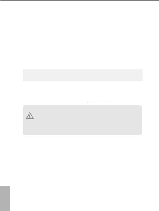
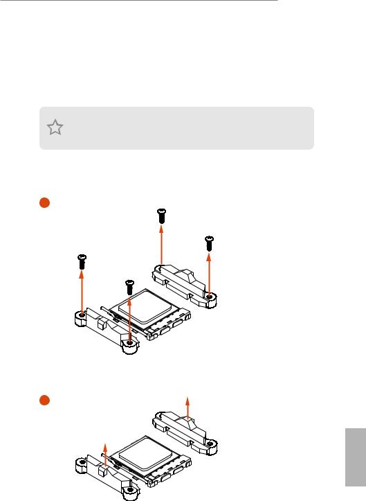
Installing the AM4 Box Cooler SR3
1
2
Page: 24
B550 Pro4
19
English
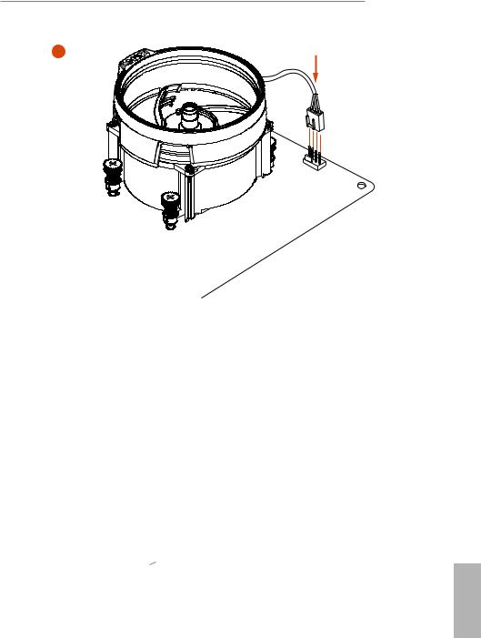
3
4
Page: 25
English
20
5
C
P
U
_
F
A
N
1
*The diagrams shown here are for reference only. The header might be in a different
position on your motherboard.
6
C
P
U
_
F
A
N
1
RGB_LED2
+12V
Page: 26
B550 Pro4
21
English
2.3 Installing Memory Modules (DIMM)
This motherboard provides four 288-pin DDR4 (Double Data Rate 4) DIMM slots,
and supports Dual Channel Memory Technology.
DDR4 UDIMM Maximum Frequency Support
Ryzen Series CPUs (Matisse):
1. For dual channel configuration, you always need to install identical (the same
brand, speed, size and chip-type) DDR4 DIMM pairs.
2. It is unable to activate Dual Channel Memory Technology with only one or three
memory module installed.
3. It is not allowed to install a DDR, DDR2 or DDR3 memory module into a DDR4
slot; otherwise, this motherboard and DIMM may be damaged.
UDIMM Memory Slot Frequency
(Mhz)
A1 A2 B1 B2
— SR — — 3200
— DR — — 3200
— SR — SR 3200
— DR — DR 3200
SR SR SR SR 2933
SR/DR DR SR/DR DR 2667
SR/DR SR/DR SR/DR SR/DR 2667
Page: 27
English
22
SR: Single rank DIMM, 1Rx4 or 1Rx8 on DIMM module label
DR: Dual rank DIMM, 2Rx4 or 2Rx8 on DIMM module label
Ryzen Series APUs (Renoir):
UDIMM Memory Slot Frequency
(Mhz)
A1 A2 B1 B2
— SR — — 3200
— DR — — 3200
— SR — SR 3200
— DR — DR 3200
SR SR SR SR 2933
SR/DR DR SR/DR DR 2667
SR/DR SR/DR SR/DR SR/DR 2667
Page: 28
B550 Pro4
23
English
The DIMM only fits in one correct orientation. It will cause permanent damage to
the motherboard and the DIMM if you force the DIMM into the slot at incorrect
orientation.
1
2
3
Page: 29
English
24
2.4 Expansion Slots (PCI Express Slots)
There are 4 PCI Express slots on the motherboard.
PCIe slots:
PCIE1 (PCIe 4.0 x16 slot) is used for PCI Express x16 lane width graphics cards.
PCIE2 (PCIe 3.0 x1 slot) is used for PCI Express x1 lane width cards.
PCIE3 (PCIe 3.0 x16 slot) is used for PCI Express x4 lane width graphics cards.
PCIE4 (PCIe 3.0 x1 slot) is used for PCI Express x1 lane width cards.
Before installing an expansion card, please make sure that the power supply is
switched off or the power cord is unplugged. Please read the documentation of the
expansion card and make necessary hardware settings for the card before you start
the installation.
PCIE1 PCIE3
Ryzen Series CPUs (Matisse) Gen4x16 Gen3x4
Ryzen Series APUs (Renoir) Gen3x16 Gen3x4
For a better thermal environment, please connect a chassis fan to the motherboard’s
chassis fan connector (CHA_FAN1/WP, CHA_FAN2/WP, CHA_FAN3/WP or
CHA_FAN4/WP) when using multiple graphics cards.
Page: 30
B550 Pro4
25
English
2.5 Jumpers Setup
The illustration shows how jumpers are setup. When the jumper cap is placed on
the pins, the jumper is “Short”. If no jumper cap is placed on the pins, the jumper is
“Open”.
Clear CMOS Jumper
(CLRCMOS1)
(see p.7, No. 22)
CLRCMOS2 allows you to clear the data in CMOS. To clear and reset the system
parameters to default setup, please turn off the computer and unplug the power
cord from the power supply. After waiting for 15 seconds, use a jumper cap to
short the pins on CLRCMOS2 for 5 seconds. However, please do not clear the
CMOS right after you update the BIOS. If you need to clear the CMOS when you
just finish updating the BIOS, you must boot up the system first, and then shut it
down before you do the clear-CMOS action. Please be noted that the password,
date, time, and user default profile will be cleared only if the CMOS battery is
removed. Please remember toremove the jumper cap after clearing the CMOS.
2-pin Jumper
Page: 31
English
26
2.6 Onboard Headers and Connectors
System Panel Header
(9-pin PANEL1)
(see p.7, No. 19)
GND
RESET#
PWRBTN#
PLED-
PLED+
GND
HDLED-
HDLED+
1
GND
Connect the power
switch, reset switch and
system status indicator on
the chassis to this header
according to the pin
assignments below. Note
the positive and negative
pins before connecting
the cables.
PWRBTN (Power Switch):
Connect to the power switch on the chassis front panel. You may configure the way to
turn off your system using the power switch.
RESET (Reset Switch):
Connect to the reset switch on the chassis front panel. Press the reset switch to restart
the computer if the computer freezes and fails to perform a normal restart.
PLED (System Power LED):
Connect to the power status indicator on the chassis front panel. The LED is on when
the system is operating. The LED keeps blinking when the system is in S3 sleep state.
The LED is off when the system is in S4 sleep state or powered off (S5).
HDLED (Hard Drive Activity LED):
Connect to the hard drive activity LED on the chassis front panel. The LED is on when
the hard drive is reading or writing data.
The front panel design may differ by chassis. A front panel module mainly consists
of power switch, reset switch, power LED, hard drive activity LED, speaker and etc.
When connecting your chassis front panel module to this header, make sure the wire
assignments and the pin assignments are matched correctly.
Onboard headers and connectors are NOT jumpers. Do NOT place jumper caps over
these headers and connectors. Placing jumper caps over the headers and connectors
will cause permanent damage to the motherboard.
Page: 32
B550 Pro4
27
English
Power LED and Speaker
Header
(7-pin SPK_PLED1)
(see p.7, No. 20) 1
+5V
DUMMY
PLED+
PLED+
PLED-
DUMMY
SPEAKER
Please connect the
chassis power LED and
the chassis speaker to this
header.
Serial ATA3 Connectors
(SATA3_1:
see p.7, No. 16)
(SATA3_2:
see p.7, No. 17)
(SATA3_3:
see p.7, No. 14)
(SATA3_4:
see p.7, No. 15)
(SATA3_5:
see p.7, No. 12)
(SATA3_6:
see p.7, No. 13)
These six SATA3
connectors support SATA
data cables for internal
storage devices with up to
6.0 Gb/s data transfer rate.
* M2_3 and SATA3_5_6
share lanes. If either one
of them is in use, the other
one will be disabled.
USB 2.0 Headers
(9-pin USB_1_2)
(see p.7, No. 24)
(9-pin USB_3_4)
(see p.7, No. 23)
DUMMY
GND
GND
P+
P-
USB_PWR
P+
P-
USB_PWR
1
There are two headers
on this motherboard.
Each USB 2.0 header can
support two ports.
USB 3.2 Gen1 Header
(19-pin USB3_7_8)
(see p.7, No. 10)
1
IntA_PB_D+
Dummy
IntA_PB_D-
GND
IntA_PB_SSTX+
GND
IntA_PB_SSTX-
IntA_PB_SSRX+
IntA_PB_SSRX-
Vbus
Vbus
Vbus
IntA_PA_SSRX-
IntA_PA_SSRX+
GND
IntA_PA_SSTX-
IntA_PA_SSTX+
GND
IntA_PA_D-
IntA_PA_D+
There is one header on
this motherboard. Each
USB 3.2 Gen1 header can
support two ports.
SATA3_1
SATA3_3
SATA3_5
SATA3_2
SATA3_4
SATA3_6
Page: 33
English
28
1. High Definition Audio supports Jack Sensing, but the panel wire on the chassis must
support HDA to function correctly. Please follow the instructions in our manual and
chassis manual to install your system.
2. If you use an AC’97 audio panel, please install it to the front panel audio header by
the steps below:
A. Connect Mic_IN (MIC) to MIC2_L.
B. Connect Audio_R (RIN) to OUT2_R and Audio_L (LIN) to OUT2_L.
C. Connect Ground (GND) to Ground (GND).
D. MIC_RET and OUT_RET are for the HD audio panel only. You don’t need to
connect them for the AC’97 audio panel.
E. To activate the front mic, go to the “FrontMic” Tab in the Realtek Control panel
and adjust “Recording Volume”.
Front Panel Audio Header
(9-pin HD_AUDIO1)
(see p.7, No. 30)
J_SENSE
OUT2_L
1
MIC_RET
PRESENCE#
GND
OUT2_R
MIC2_R
MIC2_L
OUT_RET
This header is for
connecting audio devices
to the front audio panel.
Chassis Fan / Waterpump
Fan Connectors
(4-pin CHA_FAN1/WP)
(see p.7, No. 21)
(4-pin CHA_FAN2/WP)
(see p.7, No. 25)
(4-pin CHA_FAN3/WP)
(see p.7, No. 31)
(4-pin CHA_FAN4/WP)
(see p.7, No. 26)
GND
FAN_VOLTAGE_CONTROL
FAN_SPEED
FAN_SPEED_CONTROL
FAN_SPEED
FAN_SPEED_CONTROL
FAN_VOLTAGE
GND
4
3
2
1
GND
FAN_VOLTAGE_CONTROL
FAN_SPEED
FAN_SPEED_CONTROL
Please connect fan cables
to the fan connectors and
match the black wire to
the ground pin.
CPU Fan Connector
(4-pin CPU_FAN1)
(see p.7, No. 4)
GND
FAN_VOLTAGE
CPU_FAN_SPEED
FAN_SPEED_CONTROL
1 2 3 4
This motherboard pro-
vides a 4-Pin CPU fan
(Quiet Fan) connector.
If you plan to connect a
3-Pin CPU fan, please
connect it to Pin 1-3.
Page: 34
B550 Pro4
29
English
CPU Fan / Waterpump
Fan Connector
(4-pin CPU_FAN2/WP)
(see p.7, No. 1)
GND
FAN_VOLTAGE
CPU_FAN_SPEED
FAN_SPEED_CONTROL
1 2 3 4
This motherboard pro-
vides a 4-Pin CPU fan
(Quiet Fan) connector.
If you plan to connect a
3-Pin CPU fan, please
connect it to Pin 1-3.
ATX Power Connector
(24-pin ATXPWR1)
(see p.7, No. 9)
12
1
24
13
This motherboard pro-
vides a 24-pin ATX power
connector. To use a 20-pin
ATX power supply, please
plug it along Pin 1 and Pin
13.
ATX 12V Power
Connector
(8-pin ATX12V1)
(see p.7, No. 2)
This motherboard
provides a 8-pin ATX 12V
power connector. To use a
4-pin ATX power supply,
please plug it along Pin 1
and Pin 5.
ATX 12V Power
Connector
(4-pin ATX12V2)
(see p.7, No. 3)
Please connect an ATX
12V power supply to this
connector.
*The power supply plug
fits into this connector in
only one orientation.
Serial Port Header
(9-pin COM1)
(see p.7, No. 29)
CCTS#1
RRTS#1
DDSR#1
DDTR#1
RRXD1
GND
TTXD1
DDCD#1
1
RRI#1
This COM1 header
supports a serial port
module.
4 1
8 5
Page: 35
English
30
SPI TPM Header
(13-pin SPI_TPM_J1)
(see p.7, No. 11)
1
SPI_DQ3
+3.3V
SPI_DQ2
SPI_CS0
TPM_Present
CLK
SPI_MISO
SPI_MOSI
GND
SPI_TPM_CS#
RST#
RSMRST#
TPM_PIRQ
This connector supports SPI
Trusted Platform Module (TPM)
system, which can securely
store keys, digital certificates,
passwords, and data. A TPM
system also helps enhance
network security, protects digital
identities, and ensures platform
integrity.
RGB LED Headers
(4-pin RGB_LED1)
(see p.7, No. 28)
(4-pin RGB_LED2)
(see p.7, No. 7)
12V G R B
1
RGB headers are used to connect
RGB LED extension cables which
allow users to choose from
various LED lighting effects.
Caution: Never install the
RGB LED cable in the wrong
orientation; otherwise, the cable
may be damaged.
*Please refer to page 54 for
further instructions on this
header.
Addressable LED Headers
(3-pin ADDR_LED1)
(see p.7, No. 27)
(3-pin ADDR_LED2)
(see p.7, No. 
12V G R B
1
These headers are used to connect
Addressable LED extension ca-
bles which allow users to choose
from various LED lighting
effects.
Caution: Never install the
Addressable LED cable in the
wrong orientation; otherwise,
the cable may be damaged.
*Please refer to page 55 for
further instructions on this
header.
Page: 36
B550 Pro4
31
English
2.7 Post Status Checker
Post Status Checker (PSC) diagnoses the computer when users power on the
machine. It emits a red light to indicate whether the CPU, memory, VGA or stor-
age is dysfunctional. The lights go off if the four mentioned above are functioning
normally.
Page: 37
English
32
2.8 CrossFireXTM
and Quad CrossFireXTM
Operation Guide
This motherboard supports CrossFireXTM
and Quad CrossFireXTM
that allows you
to install up to two identical PCI Express x16 graphics cards.
2.8.1 Installing Two CrossFireXTM
-Ready Graphics Cards
Step 1
Insert one graphics card into PCIE1 slot
and the other graphics card to PCIE3 slot.
Make sure that the cards are properly
seated on the slots.
Step 2
Connect two graphics cards by installing
a CrossFire Bridge on the CrossFire Bridge
Interconnects on the top of the graphics
cards. (The CrossFire Bridge is provided
with the graphics card you purchase, not
bundled with this motherboard. Please
refer to your graphics card vendor for
details.)
1. You should only use identical CrossFireXTM
-ready graphics cards that are AMD
certified.
2. Make sure that your graphics card driver supports AMD CrossFireXTM
technology.
Download the drivers from the AMD’s website: www.amd.com
3. Make sure that your power supply unit (PSU) can provide at least the minimum
power your system requires. It is recommended to use a AMD certified PSU. Please
refer to the AMD’s website for details.
4. If you pair a 12-pipe CrossFireXTM
Edition card with a 16-pipe card, both cards will
operate as 12-pipe cards while in CrossFireXTM
mode.
5. Different CrossFireXTM
cards may require different methods to enable CrossFi-
reXTM
. Please refer to AMD graphics card manuals for detailed installation guide.
CrossFire Bridge
Page: 38
B550 Pro4
33
English
Step 3
Connect a VGA cable or a DVI cable to the
monitor connector or the DVI connec-
tor of the graphics card that is inserted to
PCIE1 slot.
Page: 39
English
34
Step 1
Power on your computer and boot into OS.
Step 2
Remove the AMD drivers if you have any VGA drivers installed in your system.
Step 3
Install the required drivers and CATALYST Control Center then restart your
computer. Please check AMD’s website for details.
2.8.2 Driver Installation and Setup
Step 4
Double-click the AMD Catalyst Control
Center icon in the Windows®
system tray.
Step 5
In the left pane, click Performance and
then AMD CrossFireXTM
. Then select
Enable AMD CrossFireX and click Apply.
Select the GPU number according to your
graphics card and click Apply.
AMD Catalyst Control Center
The Catalyst Uninstaller is an optional download. We recommend using this utility
to uninstall any previously installed Catalyst drivers prior to installation. Please
check AMD’s website for AMD driver updates.
Page: 40
B550 Pro4
35
English
2.9 M.2_SSD (NGFF) Module Installation Guide (M2_1)
The M.2, also known as the Next Generation Form Factor (NGFF), is a small size and
versatile card edge connector that aims to replace mPCIe and mSATA. The Hyper M.2
Socket supports M Key type 2260/2280/22110 M.2 PCI Express module up to Gen4x4 (64
Gb/s) (with Matisse) or Gen3x4 (32 Gb/s) (with Renoir).
Installing the M.2_SSD (NGFF) Module
Step 1
Prepare a M.2_SSD (NGFF) module
and the screw.
Step 2
Depending on the PCB type and
length of your M.2_SSD (NGFF)
module, find the corresponding nut
location to be used.
No. 1 2 3
Nut Location A B C
PCB Length 6cm 8cm 11cm
Module Type Type 2260 Type2280 Type 22110
1
2
3
A
B
C
Page: 41
English
36
1
1
2
Step 3
Before installing a M.2
(NGFF) SSD module, please
loosen the screws to remove
the M.2 heatsink.
*Please remove the protective
films on the bottom side of
the M.2 heatsink before you
install a M.2 SSD module.
Step 4
Prepare the M.2 standoff that comes
with the package. Then hand tighten
the standoff into the desired nut
location on the motherboard. Align
and gently insert the M.2 (NGFF)
SSD module into the M.2 slot. Please
be aware that the M.2 (NGFF) SSD
module only fits in one orientation.
Step 5
Tighten the screw with a screwdriver
to secure the module into place.
Please do not overtighten the screw
as this might damage the module.
A
B
C
A
B
C 20o
NUT1
NUT2
C
Page: 42
B550 Pro4
37
English
M.2_SSD (NGFF) Module Support List
For the latest updates of M.2_SSD (NFGG) module support list, please visit our website for
details: http://www.asrock.com
Vendor Interface P/N
ADATA PCIe3 x4 ASX7000NP-128GT-C
ADATA PCIe3 x4 ASX8000NP-256GM-C
ADATA PCIe3 x4 ASX7000NP-256GT-C
ADATA PCIe3 x4 ASX8000NP-512GM-C
ADATA PCIe3 x4 ASX7000NP-512GT-C
Apacer PCIe3 x4 AP240GZ280
Corsair PCIe3 x4 CSSD-F240GBMP500
Intel PCIe3 x4 SSDPEKKF256G7
Intel PCIe3 x4 SSDPEKKF512G7
Kingston PCIe3 x4 SKC1000/480G
Kingston PCIe2 x4 SH2280S3/480G
OCZ PCIe3 x4 RVD400 -M2280-512G (NVME)
PATRIOT PCIe3 x4 PH240GPM280SSDR NVME
Plextor PCIe3 x4 PX-128M8PeG
Plextor PCIe3 x4 PX-1TM8PeG
Plextor PCIe3 x4 PX-256M8PeG
Plextor PCIe3 x4 PX-512M8PeG
Plextor PCIe PX-G256M6e
Plextor PCIe PX-G512M6e
Samsung PCIe3 x4 SM961 MZVPW128HEGM (NVM)
Samsung PCIe3 x4 PM961 MZVLW128HEGR (NVME)
Samsung PCIe3 x4 960 EVO (MZ-V6E250) (NVME)
Samsung PCIe3 x4 960 EVO (MZ-V6E250BW) (NVME)
Samsung PCIe3 x4 SM951 (NVME)
Samsung PCIe3 x4 SM951 (MZHPV256HDGL)
Samsung PCIe3 x4 SM951 (MZHPV512HDGL)
Samsung PCIe3 x4 SM951 (NVME)
Samsung PCIe x4 XP941-512G (MZHPU512HCGL)
SanDisk PCIe SD6PP4M-128G
SanDisk PCIe SD6PP4M-256G
TEAM PCIe3 x4 TM8FP2240G0C101
TEAM PCIe3 x4 TM8FP2480GC110
WD PCIe3 x4 WDS256G1X0C-00ENX0 (NVME)
WD PCIe3 x4 WDS512G1X0C-00ENX0 (NVME)
Page: 43
English
38
2.10 M.2 WiFi/BT Module Installation Guide (M2_2)
The M.2, also known as the Next Generation Form Factor (NGFF), is a small size and
versatile card edge connector that aims to replace mPCIe and mSATA. The M.2 Socket (Key
E) supports type 2230 WiFi/BT module.
* The M.2 socket does not support SATA M.2 SSDs.
Installing the WiFi/BT module
Step 1
Prepare a type 2230 WiFi/BT module
and the screw.
PCB Length: 3cm
Module Type: Type2230
A
Step 2
Find the nut location to be used.
Page: 44
B550 Pro4
39
English
A
A 20o
Step 3
Gently insert the WiFi/BT module
into the M.2 slot. Please be aware
that the module only fits in one
orientation.
A
Step 4
Tighten the screw with a screwdriver
to secure the module into place.
Please do not overtighten the screw as
this might damage the module.
Page: 45
English
40
2.11 M.2_SSD (NGFF) Module Installation Guide (M2_3)
The M.2, also known as the Next Generation Form Factor (NGFF), is a small size and
versatile card edge connector that aims to replace mPCIe and mSATA. The M.2 Socket
supports type 2242/2260/2280 M.2 SATA3 6.0 Gb/s module and M.2 PCI Express module
up to Gen3 x2 (16 Gb/s).
* M2_3 and SATA3_5_6 share lanes. If either one of them is in use, the other one will be
disabled.
Installing the M.2_SSD (NGFF) Module
Step 1
Prepare a M.2_SSD (NGFF) module
and the screw.
Step 2
Depending on the PCB type and
length of your M.2_SSD (NGFF)
module, find the corresponding nut
location to be used.
No. 1 2 3
Nut Location A B C
PCB Length 4.2cm 6cm 8cm
Module Type Type 2242 Type2260 Type 2280
1
2
3
A
B
C
Page: 46
B550 Pro4
41
English
Step 3
Move the standoff based on the
module type and length.
The standoff is placed at the nut
location C by default. Skip Step 3
and 4 and go straight to Step 5 if you
are going to use the default nut.
Otherwise, release the standoff by
hand.
Step 4
Peel off the yellow protective film on
the nut to be used. Hand tighten the
standoff into the desired nut location
on the motherboard.
Step 5
Gently insert the M.2 (NGFF) SSD
module into the M.2 slot. Please
be aware that the M.2 (NGFF) SSD
module only fits in one orientation.
A
B
C
A
B
C
A
B
C
A
B
C 20o
Page: 47
English
42
Step 6
Tighten the screw with a screwdriver
to secure the module into place.
Please do not overtighten the screw
as this might damage the module.
M.2_SSD (NGFF) Module Support List
For the latest updates of M.2_SSD (NFGG) module support list, please visit our website for
details: http://www.asrock.com
Vendor Interface P/N
Intel PCIe INTEL 6000P-SSDPEKKF256G7 (nvme)
Intel PCIe INTEL 6000P-SSDPEKKF512G7 (nvme)
Intel PCIe INTEL 600P-SSDPEKKW256G7-256GB (nvme)
Kingston PCIe Kingston SHPM2280P2 / 240G (Gen2 x4)
SanDisk PCIe SanDisk-SD6PP4M-128G(Gen2 x2)
Samsung PCIe Samsung XP941-MZHPU512HCGL(Gen2x4)
NUT1
NUT2
C
Page: 48
B550 Pro4
43
English
Chapter 3 Software and Utilities Operation
3.1 Installing Drivers
The Support CD that comes with the motherboard contains necessary drivers and
useful utilities that enhance the motherboard’s features.
Running The Support CD
To begin using the support CD, insert the CD into your CD-ROM drive. The CD
automatically displays the Main Menu if “AUTORUN” is enabled in your computer.
If the Main Menu does not appear automatically, locate and double click on the file
“ASRSETUP.EXE” in the Support CD to display the menu.
Drivers Menu
The drivers compatible to your system will be auto-detected and listed on the
support CD driver page. Please click Install All or follow the order from top to
bottom to install those required drivers. Therefore, the drivers you install can work
properly.
Utilities Menu
The Utilities Menu shows the application software that the motherboard supports.
Click on a specific item then follow the installation wizard to install it.
Page: 49
English
44
3.2 ASRock Motherboard Utility (A-Tuning)
ASRock Motherboard Utility (A-Tuning) is ASRock’s multi purpose software suite
with a new interface, more new features and improved utilities.
3.2.1 Installing ASRock Motherboard Utility (A-Tuning)
ASRock Motherboard Utility (A-Tuning) can be downloaded from ASRock Live
Update & APP Shop. After the installation, you will find the icon “ASRock Mother-
board Utility (A-Tuning)“ on your desktop. Double-click the “ASRock Motherboard
Utility (A-Tuning)“ icon, ASRock Motherboard Utility (A-Tuning) main menu
will pop up.
3.2.2 Using ASRock Motherboard Utility (A-Tuning)
There are five sections in ASRock Motherboard Utility (A-Tuning) main menu:
Operation Mode, OC Tweaker, System Info, FAN-Tastic Tuning and Settings.
Operation Mode
Choose an operation mode for your computer.
Page: 50
B550 Pro4
45
English
OC Tweaker
Configurations for overclocking the system.
System Info
View information about the system.
*The System Browser tab may not appear for certain models.