-
Драйверы
23
-
Инструкции по эксплуатации
2

Asrock G41M-GS3 инструкция по эксплуатации
(51 страница)
- Языки:Английский
-
Тип:
PDF -
Размер:
981.52 KB
Просмотр

Asrock G41M-GS3 инструкция по эксплуатации
(136 страниц)
-
Тип:
PDF -
Размер:
3.72 MB
Просмотр
На NoDevice можно скачать инструкцию по эксплуатации для Asrock G41M-GS3. Руководство пользователя необходимо для ознакомления с правилами установки и эксплуатации Asrock G41M-GS3. Инструкции по использованию помогут правильно настроить Asrock G41M-GS3, исправить ошибки и выявить неполадки.
- Manuals
- Brands
- ASROCK Manuals
- Motherboard
- G41M-GS3
- User manual
-
Contents
-
Table of Contents
-
Bookmarks
Quick Links
G41M-GS3 / G41M-S3
User Manual
Version 1.0
Published October 2009
Copyright©2009 ASRock INC. All rights reserved.
1 1 1 1 1
Related Manuals for ASROCK G41M-GS3
Summary of Contents for ASROCK G41M-GS3
-
Page 1: User Manual
G41M-GS3 / G41M-S3 User Manual Version 1.0 Published October 2009 Copyright©2009 ASRock INC. All rights reserved. 1 1 1 1 1…
-
Page 2
(including damages for loss of profits, loss of business, loss of data, interruption of business and the like), even if ASRock has been advised of the possibility of such damages arising from any defect or error in the manual or product. -
Page 3: Table Of Contents
2.7 Jumpers Setup …………… 18 2.8 Onboard Headers and Connectors ……..20 2.9 SATAII Hard Disk Setup Guide ……..24 2.10 Serial ATA (SATA) / Serial ATAII (SATAII) Hard Disks Installation …………..25 2.11 Driver Installation Guide ……….25 2.12 Untied Overclocking Technology ……..25…
-
Page 4: Software Support
4 Software Support ……………………………… 51 4.1 Install Operating System ……….51 4.2 Support CD Information ……….51 4.2.1 Running Support CD ……….51 4.2.2 Drivers Menu …………51 4.2.3 Utilities Menu …………51 4.2.4 Contact Information ……….51…
-
Page 5: Introduction
ASRock’s commit- ment to quality and endurance. In this manual, chapter 1 and 2 contain introduction of the motherboard and step-by-step guide to the hardware installation. Chapter 3 and 4 contain the configuration guide to BIOS setup and information of the Support CD.
-
Page 6: Specifications
1 . 2 1 . 2 Specifications Specifications Specifications Specifications Specifications — Micro ATX Form Factor: 9.6-in x 7.6-in, 24.4 cm x 19.3 cm Platform — LGA 775 for Intel Core 2 Extreme / Core 2 Quad / Core ®…
-
Page 7
— 4 x SATAII 3.0 Gb/s connectors (No Support for RAID and Connector “Hot Plug” functions) (see CAUTION — 1 x ATA100 IDE connector (supports 2 x IDE devices) — 1 x Floppy connector — 1 x Print port header…
 -
Page 8
Overclocking may affect your system stability, or even cause damage to the components and devices of your system. It should be done at your own risk and expense. We are not responsible for possible damage caused by overclocking. -
Page 9
USB flash drive or hard drive must use FAT32/16/12 file system. 13. The software name itself – OC DNA literally tells you what it is capable of. OC DNA, an exclusive utility developed by ASRock, provides a conve- nient way for the user to record the OC settings and share with others. -
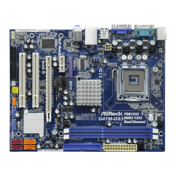
Page 10: Motherboard Layout
USB 2.0 Header (USB4_5, Blue) North Bridge Controller System Panel Header (PANEL1, Orange) CPU Fan Connector (CPU_FAN1) BIOS SPI Chip 2 x 240-pin DDR3 DIMM Slots Chassis Fan Connector (CHA_FAN1) (Dual Channel: DDR3_A1, DDR3_B1; Blue) Floppy Connector (FLOPPY1) ATX Power Connector (ATXPWR1)
-
Page 11: I/O Panel
100Mbps connection Green 1Gbps connection LAN Port * To enable Multi-Streaming function, you need to connect a front panel audio cable to the front panel audio header. Please refer to below steps for the software setting of Multi-Streaming. For Windows ®…
-
Page 12: Installation
Chapter 2 Installation Chapter 2 Installation G41M-GS3 / G41M-S3 is a Micro ATX form factor (9.6″ x 7.6″, 24.4 x 19.3 cm) motherboard. Before you install the motherboard, study the configuration of your chassis to ensure that the motherboard fits into it.
-
Page 13: Cpu Installation
Before you insert the 775-LAND CPU into the socket, please check if the CPU surface is unclean or if there is any bent pin on the socket. Do not force to insert the CPU into the socket if above situation is found.
-
Page 14
PnP cap to assist in removal. 1. It is recommended to use the cap tab to handle and avoid kicking off the PnP cap. 2. This cap must be placed if returning the motherboard for after service. -
Page 15: Installation Of Heatsink And Cpu Fan
CPU and the heatsink to improve heat dissipation. Ensure that the CPU and the heatsink are securely fastened and in good contact with each other. Then connect the CPU fan to the CPU_FAN connector (CPU_FAN1, see page 10, No.
-
Page 16: Installation Of Memory Modules (Dimm)
DIMMs or the system components. Step 1. Unlock a DIMM slot by pressing the retaining clips outward. Step 2. Align a DIMM on the slot such that the notch on the DIMM matches the break on the slot. notch break…
-
Page 17: Expansion Slots (Pci And Pci Express Slots)
2.6 Expansion Slots (PCI and PCI Express Slots) 2.6 Expansion Slots (PCI and PCI Express Slots) There are 2 PCI slots and 2 PCI Express slots on this motherboard. PCI slots: PCI slots are used to install expansion cards that have the 32-bit PCI interface. PCIE slots: PCIE1 (PCIE x1 slot) is used for PCI Express cards with x1 lane width cards, such as Gigabit LAN card, SATA2 card, etc.
-
Page 18: Jumpers Setup
2-pin jumper (see p.10 No.
Note: CLRCMOS1 allows you to clear the data in CMOS. The data in CMOS includes system setup information such as system password, date, time, and system setup parameters. To clear and reset the system parameters to default setup, please turn off the computer and unplug the power cord from the power supply. -
Page 19: Fsb1/Fsb2/Fsb3 Jumper
FSB3: 1-2 Overclocking Setting: When you mount a FSB800 or FSB1066 CPU, and try to overclock to FSB1333 (by BIOS setting) you may face the problem, that DRAM frequency will be overclocked very high. Please use jumper to force NB to be strapped at higher frequency, so the DRAM can work at lower frequency.
-
Page 20: Onboard Headers And Connectors
(33-pin FLOPPY1) FLOPPY1 Pin1 (see p.10 No. 20) the red-striped side to Pin1 Note: Make sure the red-striped side of the cable is plugged into Pin1 side of the connector. Primary IDE connector (Blue) (39-pin IDE1, see p.10 No. 7) IDE1…
-
Page 21
HDA to function correctly. Please follow the instruction in our manual and chassis manual to install your system. 2. If you use AC’97 audio panel, please install it to the front panel audio header as below: A. -
Page 22
Though this motherboard provides 4-Pin CPU fan (Quiet Fan) support, the 3-Pin CPU fan still can work successfully even without the fan speed control function. If you plan to connect the 3-Pin CPU fan to the CPU fan connector on this motherboard, please connect it to Pin 1-3. -
Page 23
(see p.10 No. 6) Though this motherboard provides 24-pin ATX power connector, it can still work if you adopt a traditional 20-pin ATX power supply. To use the 20-pin ATX power supply, please plug your power supply along with Pin 1 and Pin 13. -
Page 24: Sataii Hard Disk Setup Guide
Before installing SATAII hard disk to your computer, please carefully read below SATAII hard disk setup guide. Some default setting of SATAII hard disks may not be at SATAII mode, which operate with the best performance. In order to enable SATAII function, please follow the below instruction with different vendors to correctly adjust your SATAII hard disk to SATAII mode in advance;…
-
Page 25: Installation
STEP 2: Connect the SATA power cable to the SATA / SATAII hard disk. STEP 3: Connect one end of the SATA data cable to the motherboard’s SATAII connector. STEP 4: Connect the other end of the SATA data cable to the SATA / SATAII hard disk. 2 . 1 1 2 .
-
Page 26: Introduction
<Del> during the Power-On-Self-Test (POST) to enter the BIOS SETUP UTILITY, otherwise, POST will continue with its test routines. If you wish to enter the BIOS SETUP UTILITY after POST, restart the system by pressing <Ctl> + <Alt> + <Delete>, or by pressing the reset button on the system chassis.
-
Page 27: Navigation Keys
To jump to the Exit Screen or exit the current screen <ESC> 3.2 Main Screen Main Screen Main Screen Main Screen Main Screen When you enter the BIOS SETUP UTILITY, the Main screen will appear and display the system overview G41M-GS3 BIOS SETUP UTILITY OC Tweaker Advanced H/W Monitor…
-
Page 28
System Date [Fri 10/16/2009] Use [+] or [-] to configure system Time. BIOS Version : G41M-S3 P1.00 Processor Type : Intel (R) Core (TM) 2 Duo CPU E6850 @ 3.00GHz (64bit) Processor Speed : 3148MHz Microcode Update : 6FB/B6 Select Screen… -
Page 29: Oc Tweaker Screen
[400MHz DDR3_800], [533MHz DDR3_1066] or [667MHz DDR3_1333]. The configuration options depend on the CPU and memory module you adopt on this motherboard. Please refer to page 8 for the CPU FSB frequency and its corresponding memory support frequency. DRAM Command Rate Use this item to adjust DRAM Command Rate.
-
Page 30
Exit v02.54 (C) Copyright 1985-2003, American Megatrends, Inc. DRAM tCL This controls the number of DRAM clocks for TCL. Min: 5. Max: 10. The default value is [Auto]. DRAM tRCD This controls the number of DRAM clocks for TRCD. Min: 3. Max: 10. The default value is [Auto]. -
Page 31
Ratio CMOS Setting If the ratio status is unlocked, you will find this item appear to allow you changing the ratio value of this motherboard. If the CPU you adopt supports EIST (Intel (R) SpeedStep(tm) tech.), and you plan to adjust the ratio value, please disable the option “… -
Page 32: Advanced Screen
GLTREF Voltage Use this to select GLTREF Voltage. Configuration options: [Auto], [0.67 x Vtt], [0.65 x Vtt], [0.63 x Vtt] and [0.615 x Vtt]. The default value of this feature is [Auto]. Would you like to save current setting user defaults? In this option, you are allowed to load and save three user defaults according to your own requirements.
-
Page 33: Cpu Configuration
Ratio CMOS Setting If the ratio status is unlocked, you will find this item appear to allow you changing the ratio value of this motherboard. If the CPU you adopt supports EIST (Intel (R) SpeedStep(tm) tech.), and you plan to adjust the ratio value, please disable the option “…
-
Page 34
On-Demand Clock Modulation This provides the On-Demand Clock Modulation duty cycle. It indicates the clock on to clock off interval ratio. For example, if you set this option to [75.0% On], your processor will work normally 75% of the time, and spend the other 25% slacking off. -
Page 35: Chipset Configuration
DRAM CH1 G5 (Clocks2) v02.54 (C) Copyright 1985-2005, American Megatrends, Inc. DRAM CH0 RCOMP ODT This controls the number of DRAM CH0 RCOMP ODT. Min: 1. Max: 63. The default value is [Auto]. DRAM CH0 G0 (Data) This controls the number of DRAM CH0 G0 (Data). Min: 1. Max: 15. The default value is [Auto].
-
Page 36
DRAM CH0 G3 (Control2) This controls the number of DRAM CH0 G3 (Control2). Min: 1. Max: 15. The default value is [Auto]. DRAM CH0 G4 (Clocks1) This controls the number of DRAM CH0 G4 (Clocks1). Min: 1. Max: 15. The default value is [Auto]. -
Page 37
This controls the number of DRAM CH0 CLKSET1 SKEW. The default value is [Auto]. DRAM CH0 CMD SKEW This controls the number of DRAM CH0 CMD SKEW. The default value is [Auto]. DRAM CH0 CTRL0 SKEW This controls the number of DRAM CH0 CTRL0 SKEW. The default value is [Auto]. -
Page 38
DRAM CH1 CMD SKEW This controls the number of DRAM CH1 CMD SKEW. The default value is [Auto]. DRAM CH1 CTRL0 SKEW This controls the number of DRAM CH1 CTRL0 SKEW. The default value is [Auto]. DRAM CH1 CTRL1 SKEW This controls the number of DRAM CH1 CTRL1 SKEW. -
Page 39
DVMT/FIXED Memory You are allowed to adjust the shared memory size in this item if you set DVMT Mode Select as [DVMT Mode]. Configuration options: [128MB], [256MB] and [Maximum DVMT]. The option [Maximum DVMT] only appears when you adopt the memory module with 1024MB or above. -
Page 40
OnBoard Lan This allows you to enable or disable the “OnBoard Lan” feature. -
Page 41: Acpi Configuration
Use this item to enable or disable Ring-In signals to turn on the system from the power-soft-off mode. PCI Devices Power On Use this item to enable or disable PCI devices to turn on the system from the power-soft-off mode. PS/2 Keyboard Power On Use this item to enable or disable PS/2 keyboard to turn on the system from the power-soft-off mode.
-
Page 42: Storage Configuration
It allows you to select between [SATA 1, SATA 2, SATA 3, SATA 4], [SATA 1, SATA 3, IDE 1], [IDE 1, SATA 2, SATA 4] and [PATA Only]. If it is set to [SATA 1, SATA 3, IDE 1], then SATAII_2, SATAII_4 will not work. Likewise, if it is set to [IDE 1, SATA 2, SATA 4], then SATAII_1, SATAII_3 will not work.
-
Page 43
[ARMD]: This is used for IDE ARMD (ATAPI Removable Media Device), such as MO. LBA/Large Mode Use this item to select the LBA/Large mode for a hard disk > 512 MB under DOS and Windows; for Netware and UNIX user, select [Disabled] to disable the LBA/Large mode. -
Page 44: Pcipnp Configuration
Use this item to enable or disable the S.M.A.R.T. (Self-Monitoring, Analysis, and Reporting Technology) feature. Configuration options: [Disabled], [Auto], [Enabled]. 32-Bit Data Transfer Use this item to enable 32-bit access to maximize the IDE hard disk data transfer rate. 3.4.5 3.4.5 PCIPnP Configuration 3.4.5…
-
Page 45: Floppy Configuration
Use this item to enable or disable floppy drive controller. Serial Port Address Use this item to set the address for the onboard serial port or disable it. Configuration options: [Disabled], [3F8 / IRQ4], [2F8 / IRQ3], [3E8 / IRQ4], [2E8 / IRQ3].
-
Page 46: Usb Configuration
Parallel Port Mode Use this item to set the operation mode of the parallel port. The default value is [ECP+EPP]. If this option is set to [ECP+EPP], it will show the EPP version in the following item, “EPP Version”. Configuration options: [Normal], [Bi-Directional], and [ECP+EPP].
-
Page 47: Hardware Health Event Monitoring Screen
Hardware Health Event Monitoring Screen Hardware Health Event Monitoring Screen In this section, it allows you to monitor the status of the hardware on your system, including the parameters of the CPU temperature, motherboard temperature, CPU fan speed, chassis fan speed, and the critical voltage.
-
Page 48: Boot Screen
3.6 Boot Screen Boot Screen Boot Screen Boot Screen Boot Screen In this section, it will display the available devices on your system for you to config- ure the boot settings and the boot priority. BIOS SETUP UTILITY Main OC Tweaker…
-
Page 49: Security Screen
Boot From Onboard LAN Use this item to enable or disable the Boot From Onboard LAN feature. Boot Up Num-Lock If this item is set to [On], it will automatically activate the Numeric Lock function after boot-up. Security Screen Security Screen 3.7 Security Screen…
-
Page 50: Exit Screen
When you select this option, it will pop-out the following message, “Dis- card changes?” Select [OK] to discard all changes. Load BIOS Defaults Load BIOS default values for all the setup questions. F9 key can be used for this operation. Load Performance Setup Default (IDE/SATA) This performance setup default may not be compatible with all system configurations.
-
Page 51: Install Operating System
4 . 2 . 4 4 . 2 . 4 C o n t a c t I n f o r m a t i o n C o n t a c t I n f o r m a t i o n…
 — 1 x ATA100 IDE connector (supports 2 x IDE devices) — 1 x Floppy connector — 1 x Print port header…
 В представленном списке руководства для конкретной модели Материнской платы — ASRock G41M-GS3. Вы можете скачать инструкции к себе на компьютер или просмотреть онлайн на страницах сайта бесплатно или распечатать.
- Инструкции и файлы
- Характеристики
- Основные поломки
- Сервисы по ремонту
В случае если инструкция на русском не полная или нужна дополнительная информация по этому устройству, если вам нужны
дополнительные файлы: драйвера, дополнительное руководство пользователя (производители зачастую для каждого
продукта делают несколько различных документов технической помощи и руководств), свежая версия прошивки, то
вы можете задать вопрос администраторам или всем пользователям сайта, все постараются оперативно отреагировать
на ваш запрос и как можно быстрее помочь. Ваше устройство имеет характеристики:Socket: LGA775, Поддерживаемые процессоры: Intel Core 2 Extreme/Core 2 Quad/Core 2 Duo/Pentium Dual Core/Celeron Dual Core/Celeron, Системная шина: 533 МГц — 1333 МГц, Поддержка Hyper-Threading: есть, Поддержка многоядерных процессоров: есть, Чипсет: Intel G41, полные характеристики смотрите в следующей вкладке.
Для многих товаров, для работы с ASRock G41M-GS3 могут понадобиться различные дополнительные файлы: драйвера, патчи, обновления, программы установки. Вы можете скачать онлайн эти файлы для конкретнй модели ASRock G41M-GS3 или добавить свои для бесплатного скачивания другим посетителями.
Если вы не нашли файлов и документов для этой модели то можете посмотреть интсрукции для похожих товаров и моделей, так как они зачастую отличаются небольшим изменениями и взаимодополняемы.
Обязательно напишите несколько слов о преобретенном вами товаре, чтобы каждый мог ознакомиться с вашим отзывом или вопросом. Проявляйте активность что как можно бльше людей смогли узнать мнение настоящих людей которые уже пользовались ASRock G41M-GS3.
Георгий
2017-11-05 15:14:29
Я только приобрел.
vITALIJUS
2018-02-08 22:38:35
Материнка в ремонте.
Виталий
2018-02-08 22:49:11
Тестирование после ремонта.
Валентин
2019-04-02 12:16:21
Подключается
Anonim
2019-04-13 19:23:11
за свои деньги норм
норм
Алексей Белостоцкий
2019-08-07 09:34:46
Тестирование платы ASRock G41M-GS3 после ремонта.
АЛЕКСЕЙ
2019-08-07 17:23:32
не подключается
Подключается
Подключается
Сергей
2020-01-17 14:12:53
тестирование
СЕРГЕЙ АНАТОЛЬЕВИЧ КОЗЛОВ
2020-01-17 14:13:50
тест
Николай Оснач
2020-01-25 15:53:38
Приобрел
Не читаю бегло на техническом английском, хотел бы по-русски ознакомиться по установке джамперов системной шины на стр. 19 мануала
Настройка частоты системной шины джамперов и на русском интересует
Ваше имя
2020-02-27 16:57:03
Настроить не могу 1333 ddr3
Владас Козловский
2020-08-28 15:16:27
В моей ASRock G41M-GS3 один слот заполнен планкой памяти Patriot Memory PSD32G133381 (2 GB). В рамках установленной Win7 x64 Home Basic этого катастрофически мало.
Совместима ли PSD34G133381 (4 GB) с материнской платой платой ASRock G41M-GS3?
Как должны быть установлены джампики в этом случае?
Заранее благодарю, с уважением,
Владас
Valera
2020-09-15 21:57:45
Норм
Vasiliy
2020-11-12 10:30:20
Понравилась плата: легкая простая, удобная
Основные и самые важные характеристики модели собраны из надежных источников и по характеристикам можно найти похожие модели.
| Процессор | |
| Socket | LGA775 |
| Поддерживаемые процессоры | Intel Core 2 Extreme/Core 2 Quad/Core 2 Duo/Pentium Dual Core/Celeron Dual Core/Celeron |
| Системная шина | 533 МГц — 1333 МГц |
| Поддержка Hyper-Threading | есть |
| Поддержка многоядерных процессоров | есть |
| Чипсет | |
| Чипсет | Intel G41 |
| BIOS | AMI |
| Поддержка SLI/CrossFire | нет |
| Память | |
| Память | DDR3 DIMM, 800 — 1333 МГц |
| Количество слотов памяти | 2 |
| Поддержка двухканального режима | есть |
| Максимальный объем памяти | 8 Гб |
| Дисковые контроллеры | |
| IDE | количество слотов: 1, UltraDMA 100 |
| SATA | количество разъемов SATA 3Gb/s: 4, RAID: нет |
| Слоты расширения | |
| Слоты расширения | 1xPCI-E x16, 1xPCI-E x1, 2xPCI |
| Аудио/видео | |
| Звук | 5.1CH, HDA, на основе Realtek ALC662 |
| Встроенный видеоадаптер | есть, на основе Intel GMA X4500 |
| Сеть | |
| Ethernet | 1000 Мбит/с, на основе Realtek RTL8111DL |
| Подключение | |
| Наличие интерфейсов | 8 USB, 1xCOM, D-Sub, Ethernet, PS/2 (клавиатура), PS/2 (мышь), LPT |
| Разъемы на задней панели | 4 USB, 1xCOM, D-Sub, Ethernet, PS/2 (клавиатура), PS/2 (мышь) |
| Основной разъем питания | 24-pin |
| Разъем питания процессора | 4-pin |
| Дополнительные параметры | |
| Форм-фактор | microATX |
Здесь представлен список самых частых и распространенных поломок и неисправностей у Материнских плат. Если у вас такая поломка то вам повезло, это типовая неисправность для ASRock G41M-GS3 и вы можете задать вопрос о том как ее устранить и вам быстро ответят или же прочитайте в вопросах и ответах ниже.
| Название поломки | Описание поломки | Действие |
|---|---|---|
| Разрыв Печатных Проводников | ||
| Обрыв Конденсаторов Или Резисторов | ||
| Короткое Замыкание В Электрических Цепях | ||
| Разрушение Разъемов И Слотов | ||
| Поломка Процессорного Разъема | ||
| Выгорание Портов | ||
| Микротрещины В Плате | ||
| Выход Из Строя Сетевого Адаптера | ||
| Перегрев Компонентов | ||
| Не Запускается При Включении | При Включении Не Загружается. В Биос Не Входит. Пост Код — А3 | |
| Какой Компонент | Подскажите Марку Траyзистора Q46? | |
| Не Работает Ps/2 | Сначала Отвалилась Клавиатура, А Через Некоторое Время 6 Коротких Гудков И Не Запускается | |
| Подключить Переднюю Панель | Не Могу Подключить Переднюю Панель | |
| Судя По Всему Отвал Биоса | Материнка Стартует Секунд На 5,Кулер Процессора Берет Обороты И Останавливается.и Так-Циклически,Без Остановок.запуск Невозможен.вечером Либо Завтра Буду Пытаться Его Восстановить,Потом Может Дополню | |
| Пропал Звук На Материнке | Пропал Звук На Материнке, Отображается Только Nvidia Hdmi. Переустановка Драйверов С Офсайта Не Помогла. | |
| Биос | При Старте Звук Через Промежетки Времени Примерно В 1-3 Мин Три Сигнала Потом Стартует Винда , Недавно Вообще Написал Cmos Setting Wrong И C7, Жму Del Меняется На B2 Чтоб Воити В Биос Три Сигнала По Одному Через Промеежутки Времени 1-3 Мин И Черный Экра | |
| Asus M2A-Vm Hdmi | Не Запускается Процессор Phenom Ii X4 945 Rev. C3, На Socket-Ам 3, Нет Даже Сигнала, Черный Экран | |
| Не Включается | После Замены Конденсаторов С34 И С35 Не Включается | |
| Черный Экран | Все Уже Перепробовал И Озу Менял И Переставлял И Ластиком Чистил, И Батарейку Вынимал И Измерял, И Видеокарту С Бп На Заведомо Годную Ставил Исход Один, Черный Экран И Speaker Издает 1 Длинный 2 Коротких, Если Я Не Путаю. | |
| Неправильно Отображается Память | При Установленной Памяти 4 Гигабайта В Биосе Отображается 8. Установил Одну Планку 2 Гига — Отображается 4 | |
В нашей базе сейчас зарегестрированно 18 353 сервиса в 513 города России, Беларусии, Казахстана и Украины.

КВАТРОН
⭐
⭐
⭐
⭐
⭐
Адресс:
3-й Хорошевский, пр-д, д.10
Телефон:
74957635656
Сайт:
n/a
Время работы
Будни: с 0900 до 2100
Суббота: с 1000 до 1800
Воскресенье: выходной
КОМПЬЮТЕРНЫЙ СЕРВИС NOTE1ST
⭐
⭐
⭐
⭐
⭐
Адресс:
Cущевский вал, д. 5, стр.12 оф.№Б-30
Телефон:
74955174562
Сайт:
n/a
Время работы
Время работы не указано
РЕМОНТ НОУТБУКОВ
⭐
⭐
⭐
⭐
⭐
Адресс:
Варшавское шоссе 132А
Телефон:
74957259053
Сайт:
n/a
Время работы
Время работы не указано
REMOBI
⭐
⭐
⭐
⭐
⭐
Адресс:
Ленинградский пр., 62А, ТЦ Галерея
Телефон:
74993222524
Сайт:
n/a
Время работы
Ежедневно: с 1000 до 2100
REMOBI
⭐
⭐
⭐
⭐
⭐
Адресс:
ул. 1-я Останкинская, 55, ТЦ ВДНХ
Телефон:
74993222524
Сайт:
n/a
Время работы
Ежедневно: с 1000 до 2100
Очень доволен
хочу
авпваы
Хочу купить
ирлдоьвап ькеьпрлджыкеь дзьакерджь щзрбкежбрь апкыезрбкыеджрбеджр щзапбкерл
Только приобрела,а инструкции нет
Только приобрела,а инструкции нет
Отвалился распрыскиватель
FSB1 / FSB2 / FSB3 Jumper
(FSB1, 3-pin jumper, see p.10 No. 26)
(FSB2, 5-pin jumper, see p.10 No. 26)
(FSB3, 5-pin jumper, see p.10 No. 26)
Standard Setting:
If you adopt below DRAM / CPU configuration on this motherboard, you need to
adjust the jumpers. Please follow the instructions below to set up the jumpers.
Otherwise, the CPU and memory module may not work properly on this
motherboard.
DRAM
DDR3 533
CPU
FSB533
Jumper
FSB1
Settings
FSB2
FSB3
FSB1: 2-3
FSB2: 1-2
FSB3: 2-3
Overclocking Setting:
When you mount a FSB800 or FSB1066 CPU, and try to overclock to FSB1333 (by
BIOS setting) you may face the problem, that DRAM frequency will be overclocked
very high. Please use jumper to force NB to be strapped at higher frequency, so
the DRAM can work at lower frequency.
If you want to overclock the CPU you adopt to FSB1066 on this motherboard, you
need to adjust the jumpers. Please short pin2, pin3 for FSB1 jumper, short pin4, pin5
for FSB2 jumper and pin4, pin5 for FSB3 jumper. Otherwise, the CPU may not work
properly on this motherboard. Please refer to below jumper settings.
If you want to overclock the CPU you adopt to FSB1333 on this motherboard, you
need to adjust the jumpers. Please short pin2, pin3 for FSB1 jumper, short pin3, pin4
for FSB2 jumper and pin4, pin5 for FSB3 jumper. Otherwise, the CPU may not work
properly on this motherboard. Please refer to below jumper settings.
FSB1
FSB2
FSB3
DDR3 1333
FSB1333
FSB1
FSB2
FSB3
FSB1: 1-2
FSB2: 4-5
FSB3: 1-2
FSB1
FSB2
FSB3
FSB1
FSB2
FSB3
Default
1 9
1 9
1 9
1 9
1 9
Посмотреть инструкция для Asrock G41M-GS3 бесплатно. Руководство относится к категории материнские платы, 1 человек(а) дали ему среднюю оценку 7.5. Руководство доступно на следующих языках: английский. У вас есть вопрос о Asrock G41M-GS3 или вам нужна помощь? Задайте свой вопрос здесь
Не можете найти ответ на свой вопрос в руководстве? Вы можете найти ответ на свой вопрос ниже, в разделе часто задаваемых вопросов о Asrock G41M-GS3.
Какие сертификаты Asrock G41M-GS3 имеет?
Какая ширина Asrock G41M-GS3?
Какая толщина Asrock G41M-GS3?
Инструкция Asrock G41M-GS3 доступно в русский?
Не нашли свой вопрос? Задайте свой вопрос здесь