- Manuals
- Brands
- ASROCK Manuals
- Motherboard
- G41M-VS3
Manuals and User Guides for ASROCK G41M-VS3. We have 5 ASROCK G41M-VS3 manuals available for free PDF download: User Manual, Manual, Quick Manual, Brochure
-
Драйверы
19
-
Инструкции по эксплуатации
2

Asrock G41M-VS3 инструкция по эксплуатации
(50 страниц)
- Языки:Английский
-
Тип:
PDF -
Размер:
1.05 MB
Просмотр

Asrock G41M-VS3 инструкция по эксплуатации
(120 страниц)
-
Тип:
PDF -
Размер:
3.5 MB
Просмотр
На NoDevice можно скачать инструкцию по эксплуатации для Asrock G41M-VS3. Руководство пользователя необходимо для ознакомления с правилами установки и эксплуатации Asrock G41M-VS3. Инструкции по использованию помогут правильно настроить Asrock G41M-VS3, исправить ошибки и выявить неполадки.
Посмотреть инструкция для Asrock G41M-VS3 R2.0 бесплатно. Руководство относится к категории материнские платы, 17 человек(а) дали ему среднюю оценку 9. Руководство доступно на следующих языках: английский. У вас есть вопрос о Asrock G41M-VS3 R2.0 или вам нужна помощь? Задайте свой вопрос здесь
Не можете найти ответ на свой вопрос в руководстве? Вы можете найти ответ на свой вопрос ниже, в разделе часто задаваемых вопросов о Asrock G41M-VS3 R2.0.
Какие сертификаты Asrock G41M-VS3 R2.0 имеет?
Какая ширина Asrock G41M-VS3 R2.0?
Какая толщина Asrock G41M-VS3 R2.0?
Инструкция Asrock G41M-VS3 R2.0 доступно в русский?
Не нашли свой вопрос? Задайте свой вопрос здесь
![]()
Copyright Notice:
No part of this installation guide may be reproduced, transcribed, transmitted, or translated in any language, in any form or by any means, except duplication of documentation by the purchaser for backup purpose, without written consent of ASRock Inc.
Products and corporate names appearing in this guide may or may not be registered trademarks or copyrights of their respective companies, and are used only for identification or explanation and to the owners’ benefit, without intent to infringe.
Disclaimer:
Specifications and information contained in this guide are furnished for informational use only and subject to change without notice, and should not be constructed as a commitment by ASRock. ASRock assumes no responsibility for any errors or omissions that may appear in this guide.
With respect to the contents of this guide, ASRock does not provide warranty of any kind, either expressed or implied, including but not limited to the implied warranties or conditions of merchantability or fitness for a particular purpose. In no event shall ASRock, its directors, officers, employees, or agents be liable for any indirect, special, incidental, or consequential damages (including damages for loss of profits, loss of business, loss of data, interruption of business and the like), even if ASRock has been advised of the possibility of such damages arising from any defect or error in the guide or product.
This device complies with Part 15 of the FCC Rules. Operation is subject to the following two conditions:
(1)this device may not cause harmful interference, and
(2)this device must accept any interference received, including interference that may cause undesired operation.
CALIFORNIA, USA ONLY
The Lithium battery adopted on this motherboard contains Perchlorate, a toxic substance controlled in Perchlorate Best Management Practices (BMP) regulations passed by the California Legislature. When you discard the Lithium battery in California, USA, please follow the related regulations in advance.
“Perchlorate Material-special handling may apply, see www.dtsc.ca.gov/hazardouswaste/perchlorate”
ASRock Website: http://www.asrock.com
Published December 2009
Copyright©2009 ASRock INC. All rights reserved.
1
English
ASRock G41M-VGS3 / G41M-VS3 Motherboard

Motherboard Layout
(G41M-VGS3 / G41M-VS3)
|
1 |
PS2_USB_PWR1 Jumper |
14 |
Chassis Speaker Header (SPEAKER1,Purple) |
|
2 |
ATX 12V Connector (ATX12V2) |
15 |
USB 2.0 Header (USB4_5, Blue) |
|
3 |
CPU Fan Connector (CPU_FAN1) |
16 |
Chassis Fan Connector (CHA_FAN1) |
|
4 |
ATX Power Connector (ATXPWR1) |
17 |
USB 2.0 Header (USB6_7, Blue) |
|
5 |
2 x 240-pin DDR3 DIMM Slots |
18 |
Clear CMOS Jumper (CLRCMOS1) |
|
(Dual Channel: DDR3_A1, DDR3_B1; Blue) |
19 |
BIOS SPI Chip |
|
|
6 |
North Bridge Controller |
20 |
PCI Slot (PCI1) |
|
7 |
South Bridge Controller |
21 |
EUP Audio Jumper (EUP_AUDIO1) |
|
8 |
System Panel Header (PANEL1, Orange) |
22 |
EUP LAN Jumper (EUP_LAN1) |
|
9 |
IDE1 Connector (IDE1, Blue) |
23 |
PCI Express x16 Slot (PCIE1) |
|
10 |
Primary SATAII Connector (SATAII_1; Red) |
24 |
Front Panel Audio Header |
|
11 |
Secondary SATAII Connector (SATAII_2; Red) |
(HD_AUDIO1, Lime) |
|
|
12 |
Third SATAII Connector (SATAII_3; Red) |
25 |
Print Port Header (LPT1, Purple) |
|
13 |
Fourth SATAII Connector (SATAII_4; Red) |
26 |
FSB1 Jumper |
ASRock G41M-VGS3 / G41M-VS3 Motherboard
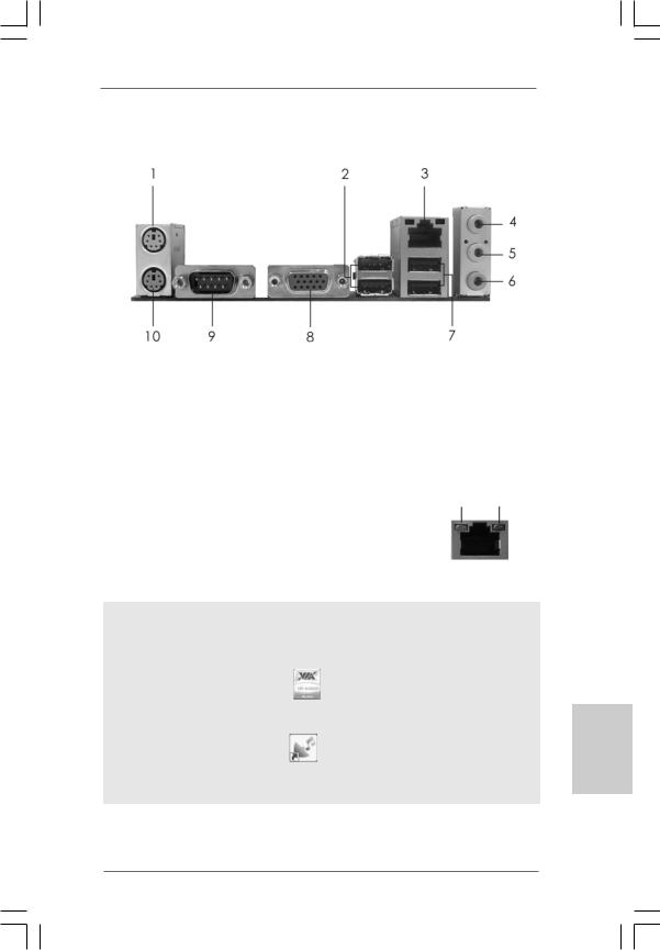
I/O Panel (G41M-VGS3)
|
1 |
PS/2 Mouse Port (Green) |
6 |
Microphone (Pink) |
|
|
2 |
USB 2.0 Ports (USB23) |
7 |
USB 2.0 Ports (USB01) |
|
|
* 3 |
RJ-45 Port |
8 |
VGA Port |
|
|
4 |
Line |
In (Light Blue) |
9 |
COM Port |
|
5 |
Line |
Out (Lime) |
10 |
PS/2 Keyboard Port (Purple) |
LAN Port LED Indications
|
Activity/Link LED |
SPEED LED |
ACT/LINK SPEED |
||||||
|
LED |
LED |
|||||||
|
Status |
Description |
Status |
Description |
|||||
|
Off |
No Activity |
Off |
10Mbps connection |
|||||
|
Blinking |
Data Activity |
Orange |
100Mbps connection |
|||||
|
Green |
1Gbps connection |
LAN Port |
||||||
To enable Multi-Streaming function, you need to connect a front panel audio cable to the front panel audio header. After restarting your computer, you will find “VIA HD Audio Deck” tool on your system. Please follow below instructions according to the OS you install.
|
For Windows® XP / XP 64-bit OS: |
|
|
Please click “VIA HD Audio Deck” icon |
, and click “Speaker”. Then you are allowed to |
select “2 Channel” or “4 Channel”. Click “Power” to save your change.
For Windows® 7 / 7 64-bit / VistaTM / VistaTM 64-bit OS:
|
Please click “VIA HD Audio Deck” icon |
, and click “Advanced Options” on the left side |
on the bottom. In “Advanced Options” screen, select “Independent Headphone”, and click “OK” to save your change.
3
English
ASRock G41M-VGS3 / G41M-VS3 Motherboard
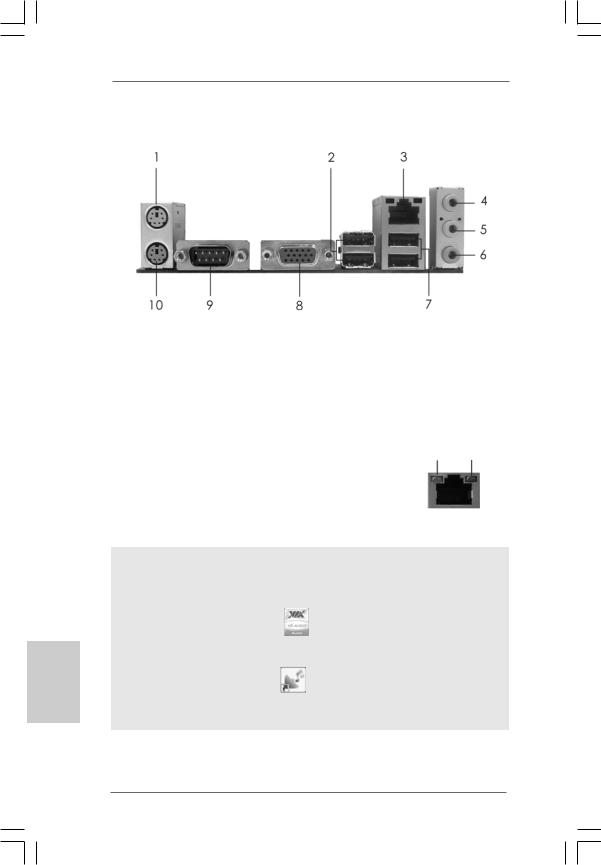
I/O Panel (G41M-VS3)
|
1 |
PS/2 Mouse Port (Green) |
6 |
Microphone (Pink) |
|
|
2 |
USB 2.0 Ports (USB23) |
7 |
USB 2.0 Ports (USB01) |
|
|
* 3 |
RJ-45 Port |
8 |
VGA Port |
|
|
4 |
Line |
In (Light Blue) |
9 |
COM Port |
|
5 |
Line |
Out (Lime) |
10 |
PS/2 Keyboard Port (Purple) |
LAN Port LED Indications
|
Activity/Link LED |
SPEED LED |
ACT/LINK SPEED |
|||||
|
LED |
LED |
||||||
|
Status |
Description |
Status |
Description |
||||
|
Off |
No Activity |
Off |
10Mbps connection |
||||
|
Blinking |
Data Activity |
Green |
100Mbps connection |
||||
LAN Port
To enable Multi-Streaming function, you need to connect a front panel audio cable to the front panel audio header. After restarting your computer, you will find “VIA HD Audio Deck” tool on your system. Please follow below instructions according to the OS you install.
|
For Windows® XP / XP 64-bit OS: |
|
|
Please click “VIA HD Audio Deck” icon |
, and click “Speaker”. Then you are allowed to |
select “2 Channel” or “4 Channel”. Click “Power” to save your change.
For Windows® 7 / 7 64-bit / VistaTM / VistaTM 64-bit OS:
|
Please click “VIA HD Audio Deck” icon |
, and click “Advanced Options” on the left side |
on the bottom. In “Advanced Options” screen, select “Independent Headphone”, and click “OK” to save your change.
ASRock G41M-VGS3 / G41M-VS3 Motherboard
/LINK SPEED ED LED
LAN Port
1. Introduction
Thank you for purchasing ASRock G41M-VGS3 / G41M-VS3 motherboard, a reliable motherboard produced under ASRock’s consistently stringent quality control. It delivers excellent performance with robust design conforming to ASRock’s commitment to quality and endurance.
This Quick Installation Guide contains introduction of the motherboard and step-by- step installation guide. More detailed information of the motherboard can be found in the user manual presented in the Support CD.
Because the motherboard specifications and the BIOS software might be updated, the content of this manual will be subject to change without notice. In case any modifications of this manual occur, the updated version will be available on ASRock website without further notice. You may find the latest VGA cards and CPU support lists on ASRock website as well. ASRock website http://www.asrock.com
If you require technical support related to this motherboard, please visit our website for specific information about the model you are using. www.asrock.com/support/index.asp
1.1 Package Contents
ASRock G41M-VGS3 / G41M-VS3 Motherboard
(Micro ATX Form Factor: 8.9-in x 6.7-in, 22.6 cm x 17.0 cm) ASRock G41M-VGS3 / G41M-VS3 Quick Installation Guide ASRock G41M-VGS3 / G41M-VS3 Support CD
Two Serial ATA (SATA) Data Cables (Optional) One I/O Panel Shield
English
5
ASRock G41M-VGS3 / G41M-VS3 Motherboard

1.2Specifications
|
Platform |
— Micro ATX Form Factor: 8.9-in x 6.7-in, 22.6 cm x 17.0 cm |
|
CPU |
— LGA 775 for Intel® CoreTM 2 Extreme / CoreTM 2 Quad / CoreTM |
|
2 Duo / Pentium® Dual Core / Celeron® Dual Core / Celeron®, |
|
|
supporting Penryn Quad Core Yorkfield and Dual Core |
|
|
Wolfdale processors |
|
|
— Supports FSB1333/1066/800/533 MHz |
|
|
— Supports Hyper-Threading Technology (see CAUTION 1) |
|
|
— Supports Untied Overclocking Technology (see CAUTION 2) |
|
|
— Supports EM64T CPU |
|
|
Chipset |
— Northbridge: Intel® G41 |
|
— Southbridge: Intel® ICH7 |
|
|
Memory |
— Dual Channel DDR3 Memory Technology (see CAUTION 3) |
|
— 2 x DDR3 DIMM slots |
|
|
— Supports DDR3 1333(OC)/1066/800 non-ECC, un-buffered |
|
|
memory (see CAUTION 4) |
|
|
— Max. capacity of system memory: 8GB (see CAUTION 5) |
|
|
Expansion Slot |
— 1 x PCI Express x16 slot |
|
— 1 x PCI slot |
|
|
Graphics |
— Intel® Graphics Media Accelerator X4500 |
|
— Pixel Shader 4.0, DirectX 10 |
|
|
— Max. shared memory 1759MB (see CAUTION 6) |
|
|
— Supports D-Sub with max. resolution up to 2048×1536 @ |
|
|
75Hz |
|
|
Audio |
— 5.1 CH HD Audio (VIA® VT1705 Audio Codec) |
|
LAN |
— G41M-VGS3 |
|
Atheros® PCIE x1 Gigabit LAN AR8131L, |
|
|
speed 10/100/1000 Mb/s |
|
|
— G41M-VS3 |
|
|
Atheros® PCIE x1 LAN AR8132L, speed 10/100 Mb/s |
|
|
— Supports Wake-On-LAN |
|
|
Rear Panel I/O |
I/O Panel |
|
— 1 x PS/2 Mouse Port |
|
|
— 1 x PS/2 Keyboard Port |
|
|
— 1 x Serial Port: COM1 |
|
|
— 1 x VGA Port |
|
|
— 4 x Ready-to-Use USB 2.0 Ports |
|
|
— 1 x RJ-45 LAN Port with LED (ACT/LINK LED and SPEED LED) |
|
|
— HD Audio Jack: Line in / Front Speaker / Microphone |
|
ASRock G41M-VGS3 / G41M-VS3 Motherboard

|
Connector |
— 4 x SATAII 3.0 Gb/s connectors (No Support for RAID and |
|
“Hot Plug” functions) (see CAUTION 7) |
|
|
— 1 x ATA100 IDE connector (supports 2 x IDE devices) |
|
|
— 1 x Print port header |
|
|
— CPU/Chassis FAN connector |
|
|
— 24 pin ATX power connector |
|
|
— 4 pin 12V power connector |
|
|
— Front panel audio connector |
|
|
— 2 x USB 2.0 headers (support 4 USB 2.0 ports) |
|
|
(see CAUTION 8) |
|
|
BIOS Feature |
— 8Mb AMI BIOS |
|
— AMI Legal BIOS |
|
|
— Supports “Plug and Play” |
|
|
— ACPI 1.1 Compliance Wake Up Events |
|
|
— AMBIOS 2.3.1 Support |
|
|
— VCCM, NB, VTT, GTLRef Voltage Multi-adjustment |
|
|
Support CD |
— Drivers, Utilities, AntiVirus Software (Trial Version), |
|
ASRock Software Suite (CyberLink DVD Suite and Creative |
|
|
Sound Blaster X-Fi MB) (OEM and Trial Version) |
|
|
Unique Feature |
— ASRock OC Tuner (see CAUTION 9) |
|
— Intelligent Energy Saver (see CAUTION 10) |
|
|
— Instant Boot |
|
|
— ASRock Instant Flash (see CAUTION 11) |
|
|
— ASRock OC DNA (see CAUTION 12) |
|
|
— Hybrid Booster: |
|
|
— CPU Frequency Stepless Control (see CAUTION 13) |
|
|
— ASRock U-COP (see CAUTION 14) |
|
|
— Boot Failure Guard (B.F.G.) |
|
|
Hardware |
— CPU Temperature Sensing |
|
Monitor |
— Chassis Temperature Sensing |
|
— CPU Fan Tachometer |
|
|
— Chassis Fan Tachometer |
|
|
— CPU Quiet Fan |
|
|
— Voltage Monitoring: +12V, +5V, +3.3V, Vcore |
|
|
OS |
— Microsoft® Windows® 7 / 7 64-bit / VistaTM / VistaTM 64-bit / XP |
|
/ XP 64-bit compliant |
|
|
Certifications |
— FCC, CE |
|
— EuP Ready (EuP ready power supply is required) |
|
|
(see CAUTION 15) |
* For detailed product information, please visit our website: http://www.asrock.com
ASRock G41M-VGS3 / G41M-VS3 Motherboard

WARNING
Please realize that there is a certain risk involved with overclocking, including adjusting the setting in the BIOS, applying Untied Overclocking Technology, or using the thirdparty overclocking tools. Overclocking may affect your system stability, or even cause damage to the components and devices of your system. It should be done at your own risk and expense. We are not responsible for possible damage caused by overclocking.
CAUTION!
1. About the setting of “Hyper Threading Technology”, please check page 33 of “User Manual” in the support CD.
2. This motherboard supports Untied Overclocking Technology. Please read
|
“Untied Overclocking Technology” on page 19 for details. |
||||
|
3. |
This motherboard supports Dual Channel Memory Technology. Before you |
|||
|
implement Dual Channel Memory Technology, make sure to read the |
||||
|
installation guide of memory modules on page 13 for proper installation. |
||||
|
4. |
Please check the table below for the CPU FSB frequency and its |
|||
|
corresponding memory support frequency. |
||||
|
CPU FSB Frequency |
Memory Support Frequency |
|||
|
1333 |
DDR3 800, DDR3 1066, DDR3 1333 |
|||
|
1066 |
DDR3 800, DDR3 1066 |
|||
|
800 |
DDR3 800 |
|||
|
533 |
DDR3 800 |
|||
|
* DDR3 1333 memory modules will operate in overclocking mode. |
||||
|
* When you use a FSB533-CPU on this motherboard, it will run at |
||||
|
DDR3 533 if you adopt a DDR3 800 memory module. |
||||
|
* If you adopt FSB1333-CPU and DDR3 1333 memory module on this |
||||
|
motherboard, you need to adjust the jumper. Please refer to page 16 for |
||||
|
proper jumper settings. |
||||
|
5. |
Due to the operating system limitation, the actual memory size may be |
|||
|
less than 4GB for the reservation for system usage under Windows® 7 / |
||||
|
VistaTM / XP. For Windows® OS with 64-bit CPU, there is no such limitation. |
||||
|
6. |
The maximum shared memory size is defined by the chipset vendor and |
|||
|
is subject to change. Please check Intel® website for the latest information. |
||||
|
7. |
Before installing SATAII hard disk to SATAII connector, please read the “SATAII |
|||
|
Hard Disk Setup Guide” on page 23 of “User Manual” in the support CD to |
||||
|
adjust your SATAII hard disk drive to SATAII mode. You can also connect SATA |
||||
|
hard disk to SATAII connector directly. |
||||
|
8. |
Power Management for USB 2.0 works fine under Microsoft® Windows® 7 |
|||
|
64-bit / 7 / VistaTM 64-bit / VistaTM / XP 64-bit / XP SP1 or SP2. |
||||
|
9. |
It is a user-friendly ASRock overclocking tool which allows you to surveil |
|||
|
your system by hardware monitor function and overclock your hardware |
||||
|
devices to get the best system performance under Windows® environment. |
||||
|
Please visit our website for the operation procedures of ASRock OC |
||||
|
Tuner. ASRock website: http://www.asrock.com |
ASRock G41M-VGS3 / G41M-VS3 Motherboard

10.Featuring an advanced proprietary hardware and software design, Intelligent Energy Saver is a revolutionary technology that delivers unparalleled power savings. In other words, it is able to provide exceptional power saving and improve power efficiency without sacrificing computing performance. Please visit our website for the operation procedures of Intelligent Energy Saver.
ASRock website: http://www.asrock.com
11.ASRock Instant Flash is a BIOS flash utility embedded in Flash ROM. This convenient BIOS update tool allows you to update system BIOS without entering operating systems first like MS-DOS or Windows®. With this utility, you can press <F6> key during the POST or press <F2> key to BIOS setup menu to access ASRock Instant Flash. Just launch this tool and save the new BIOS file to your USB flash drive, floppy disk or hard drive, then you can update your BIOS only in a few clicks without preparing an additional floppy diskette or other complicated flash utility. Please be noted that the USB flash drive or hard drive must use FAT32/16/12 file system.
12.The software name itself – OC DNA literally tells you what it is capable of. OC DNA, an exclusive utility developed by ASRock, provides a convenient way for the user to record the OC settings and share with others. It helps you to save your overclocking record under the operating system and simplifies the complicated recording process of overclocking settings. With OC DNA, you can save your OC settings as a profile and share with your friends! Your friends then can load the OC profile to their own system to get the same OC settings as yours! Please be noticed that the OC profile can only be shared and worked on the same motherboard.
13.Although this motherboard offers stepless control, it is not recommended to perform over-clocking. Frequencies other than the recommended CPU bus frequencies may cause the instability of the system or damage the CPU.
14.While CPU overheat is detected, the system will automatically shutdown. Before you resume the system, please check if the CPU fan on the motherboard functions properly and unplug the power cord, then plug it back again. To improve heat dissipation, remember to spray thermal grease between the CPU and the heatsink when you install the PC system.
15.EuP, stands for Energy Using Product, was a provision regulated by European Union to define the power consumption for the completed system. According to EuP, the total AC power of the completed system shall be under 1.00W in off mode condition. To meet EuP standard, an EuP ready motherboard and an EuP ready power supply are required. According to Intel’s suggestion, the EuP ready power supply must meet the standard of 5v standby power efficiency is higher than 50% under 100 mA current consumption. For EuP ready power supply selection, we recommend you checking with the power supply manufacturer for more details.
ASRock G41M-VGS3 / G41M-VS3 Motherboard
English
2. Installation
Pre-installation Precautions
Take note of the following precautions before you install motherboard components or change any motherboard settings.
1.Unplug the power cord from the wall socket before touching any component. Failure to do so may cause severe damage to the motherboard, peripherals, and/or components.
2.To avoid damaging the motherboard components due to static electricity, NEVER place your motherboard directly on the carpet or the like. Also remember to use a grounded wrist strap or touch a safety grounded object before you handle components.
3.Hold components by the edges and do not touch the ICs.
4.Whenever you uninstall any component, place it on a grounded antstatic pad or in the bag that comes with the component.
5.When placing screws into the screw holes to secure the motherboard to the chassis, please do not over-tighten the screws! Doing so may damage the motherboard.
2.1CPU Installation
For the installation of Intel 775-LAND CPU, please follow the steps below.
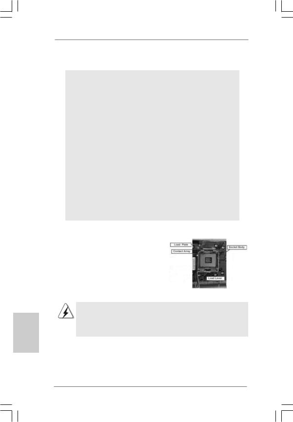
775-Pin Socket Overview
Before you insert the 775-LAND CPU into the socket, please check if the CPU surface is unclean or if there is any bent pin on the socket. Do not force to insert the CPU into the socket if above situation is found. Otherwise, the CPU will be seriously damaged.
10
ASRock G41M-VGS3 / G41M-VS3 Motherboard
![]()
Step 1. Open the socket:
Step 1-1. Disengaging the lever by depressing down and out on the hook to clear retention tab.
Step 1-2. Rotate the load lever to fully open position at approximately 135 degrees.
Step 1-3. Rotate the load plate to fully open position at approximately 100 degrees.
Step 2. Insert the 775-LAND CPU:
Step 2-1. Hold the CPU by the edges where are marked with black lines.
Step 2-2. Orient the CPU with IHS (Integrated Heat Sink) up. Locate Pin1 and the two orientation key notches.
|
Pin1 |
Pin1 |
||
|
alignment key |
|||
|
orientation |
orientation |
alignment key |
|
|
key notch |
key notch |
||
|
775-Pin Socket |
|||
|
775-LAND CPU |
For proper inserting, please ensure to match the two orientation key notches of the CPU with the two alignment keys of the socket.
Step 2-3. Carefully place the CPU into the socket by using a purely vertical motion.
Step 2-4. Verify that the CPU is within the socket and properly mated to the orient keys.
Step 3. Remove PnP Cap (Pick and Place Cap):
Use your left hand index finger and thumb to support the load plate edge, engage PnP cap with right hand thumb and peel the cap from the socket while pressing on center of PnP cap to assist in removal.
11
English
ASRock G41M-VGS3 / G41M-VS3 Motherboard
1.It is recommended to use the cap tab to handle and avoid kicking off the PnP cap.
2.This cap must be placed if returning the motherboard for after service.
Step 4. Close the socket:
Step 4-1. Rotate the load plate onto the IHS. Step 4-2. While pressing down lightly on load
plate, engage the load lever.
Step 4-3. Secure load lever with load plate tab under retention tab of load lever.
2.2Installation of CPU Fan and Heatsink
For proper installation, please kindly refer to the instruction manuals of your CPU fan and heatsink.
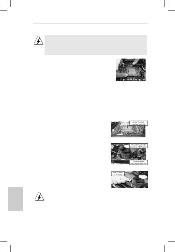
Below is an example to illustrate the installation of the heatsink for 775-LAND CPU. Step 1. Apply thermal interface material onto center
of IHS on the socket surface.
English
|
Step 2. |
Place the heatsink onto the socket. Ensure |
|
fan cables are oriented on side closest to the |
|
|
CPU fan connector on the motherboard |
|
|
(CPU_FAN1, see page 2, No. 3). |
|
|
Step 3. |
Align fasteners with the motherboard |
|
throughholes. |
|
|
Step 4. |
Rotate the fastener clockwise, then press |
|
down on fastener caps with thumb to install |
|
|
and lock. Repeat with remaining fasteners. |
|
|
If you press down the fasteners without rotating them clockwise, |
|
|
the heatsink cannot be secured on the motherboard. |
|
|
Step 5. |
Connect fan header with the CPU fan |
|
connector on the motherboard. |
|
|
Step 6. |
Secure excess cable with tie-wrap to ensure |
|
cable does not interfere with fan operation or |
|
|
contact other components. |
12
ASRock G41M-VGS3 / G41M-VS3 Motherboard
2.3 Installation of Memory Modules (DIMM)
G41M-VGS3 / G41M-VS3 motherboard provides two 240-pin DDR3 (Double Data Rate 3) DIMM slots, and supports Dual Channel Memory Technology. For dual channel configuration, you always need to install two identical (the same brand, speed, size and chip-type) memory modules in the DDR3 DIMM slots to activate Dual Channel Memory Technology. Otherwise, it will operate at single channel mode.
1.It is not allowed to install a DDR or DDR2 memory module into DDR3 slot;otherwise, this motherboard and DIMM may be damaged.
2.If you install only one memory module or two non-identical memory modules, it is unable to activate the Dual Channel Memory Technology.
Installing a DIMM
Please make sure to disconnect power supply before adding or removing DIMMs or the system components.
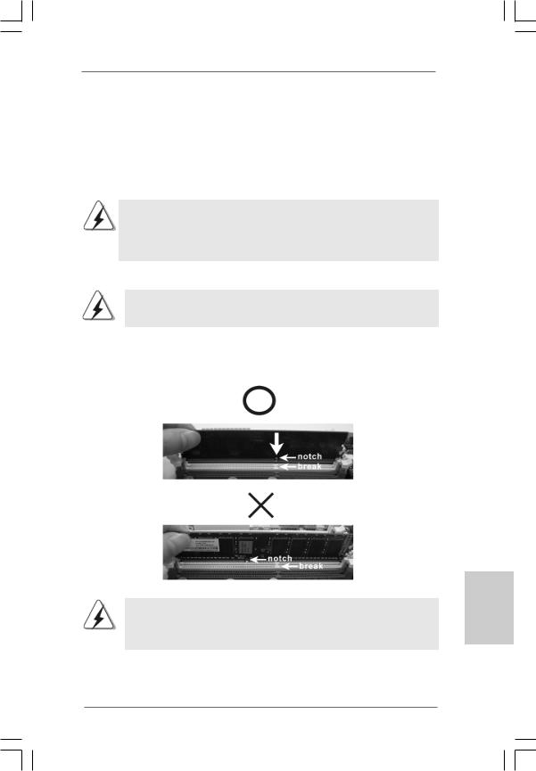
Step 1. Unlock a DIMM slot by pressing the retaining clips outward.
Step 2. Align a DIMM on the slot such that the notch on the DIMM matches the break on the slot.
The DIMM only fits in one correct orientation. It will cause permanent damage to the motherboard and the DIMM if you force the DIMM into the slot at incorrect orientation.
Step 3. Firmly insert the DIMM into the slot until the retaining clips at both ends fully snap back in place and the DIMM is properly seated.
13
English
ASRock G41M-VGS3 / G41M-VS3 Motherboard
2.4 Expansion Slots (PCI and PCI Express Slots)
There are 1 PCI slot and 1 PCI Express slot on this motherboard.
PCI slot: PCI slot is used to install expansion cards that have the 32-bit PCI interface.
PCIE slot:
PCIE1 (PCIE x16 slot) is used for PCI Express cards with x16 lane width graphics cards.
If you install the add-on PCI Express VGA card to PCIE1 (PCIE x16 slot), the onboard VGA will be disabled. If you install the add-on PCI Express VGA card to PCIE1 (PCIE x16 slot) and adjust the BIOS options “Primary Graphics Adapter” to [Onboard] and “Share Memory” to [Auto], then the onboard VGA will be enabled, and the primary screen will be onboard VGA.
Installing an expansion card
Step 1. Before installing the expansion card, please make sure that the power supply is switched off or the power cord is unplugged. Please read the documentation of the expansion card and make necessary hardware settings for the card before you start the installation.
Step 2. Remove the bracket facing the slot that you intend to use. Keep the screws for later use.
Step 3. Align the card connector with the slot and press firmly until the card is completely seated on the slot.
Step 4. Fasten the card to the chassis with screws.
English
14
ASRock G41M-VGS3 / G41M-VS3 Motherboard
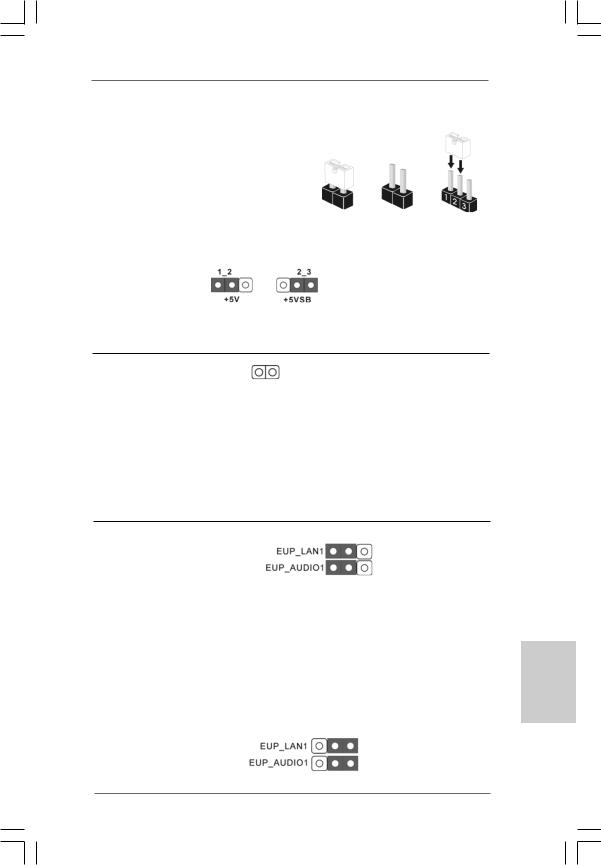
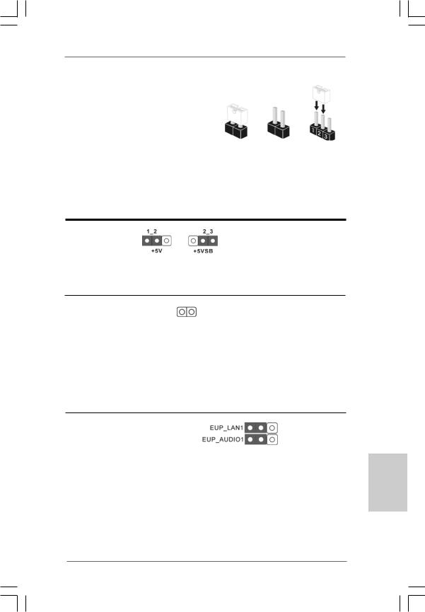
2.5 Jumpers Setup
|
The illustration shows how jumpers are |
||||
|
setup. When the jumper cap is placed on |
||||
|
pins, the jumper is “Short”. If no jumper cap |
||||
|
is placed on pins, the jumper is “Open”. The |
||||
|
illustration shows a 3-pin jumper whose pin1 |
Short |
Open |
||
|
and pin2 are “Short” when jumper cap is |
||||
|
placed on these 2 pins. |
||||
|
Jumper |
Setting |
Description |
||
|
PS2_USB_PWR1 |
Short pin2, pin3 to enable |
|||
|
(see p.2 No. 1) |
+5VSB (standby) for PS/2 |
|||
|
or USB wake up events. |
Note: To select +5VSB, it requires 2 Amp and higher standby current provided by power supply.
Clear CMOS
(CLRCMOS1, 2-pin jumper)
(see p.2 No. 18) 2-pin jumper
Note: CLRCMOS1 allows you to clear the data in CMOS. The data in CMOS includes system setup information such as system password, date, time, and system setup parameters. To clear and reset the system parameters to default setup, please turn off the computer and unplug the power cord from the power supply. After waiting for 15 seconds, use a jumper cap to short 2 pins on CLRCMOS1 for 5 seconds.
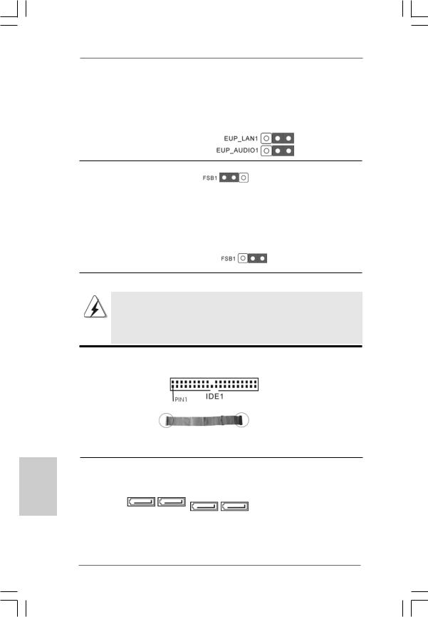
EUP LAN / EUP Audio Jumper
|
(EUP_LAN1, 3-pin jumper, see p.2 No. 22) |
Default (Enable EuP) |
|
(EUP_AUDIO1, 3-pin jumper, see p.2 No. 21) |
Note: EUP_LAN and EUP_AUDIO jumper design decreases the power consumption of this motherboard to meet EuP standard. With an ASRock EuP ready motherboard and a power supply that the 5VSB power efficiency is higher than 50% under 100mA current consumption, your system is able to submit
EuP standard. The default setting (short pin1 and pin2) is EuP enabled. If you want to disable this power saving function, you may short pin2 and pin3. Please be noticed that when EUP_LAN jumper is set to enabled, the Wake-On-LAN function under S3 (Suspend to RAM), S4 (Suspend to Disk), and S5 (Soft Off) will be disabled.
(Disable EuP)
15
English
ASRock G41M-VGS3 / G41M-VS3 Motherboard
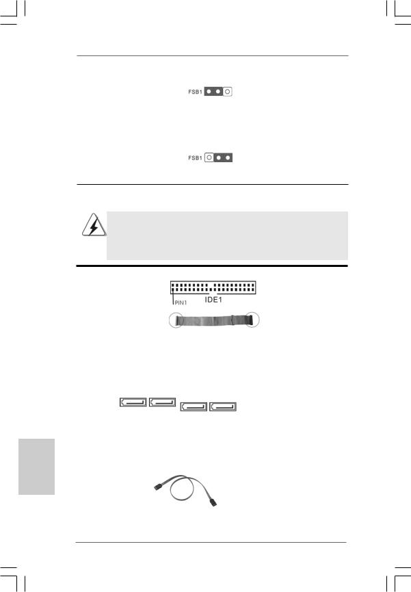
FSB1 Jumper
|
(FSB1, 3-pin jumper, see p.2 No. 26) |
Default |
If you adopt FSB1333-CPU and DDR3 1333 memory module on this motherboard, you need to adjust the jumper. Please short pin2, pin3 for FSB1 jumper. Otherwise, the CPU and memory module may not work properly on this motherboard. Please refer to below jumper setting.
English
2.6 Onboard Headers and Connectors
Onboard headers and connectors are NOT jumpers. Do NOT place jumper caps over these headers and connectors. Placing jumper caps over the headers and connectors will cause permanent damage of the motherboard!
Primary IDE connector (Blue)
(39-pin IDE1, see p.2 No. 9)
|
connect the blue end |
connect the black end |
||
|
to the motherboard |
to the IDE devices |
||
|
80-conductor ATA 66/100 cable |
|||
|
Note: Please refer to the instruction of your IDE device vendor for the details. |
|||
|
Serial ATAII Connectors |
These Serial ATAII (SATAII) |
||
|
(SATAII_1: |
connectors support SATAII |
||
|
see p.2, No. 10) |
or SATA hard disk for internal |
||
|
(SATAII_2: |
SATAII_4 SATAII_3 |
storage devices. The current |
|
|
see p.2, No. 11) |
SATAII_2 SATAII_1 SATAII interface allows up to |
||
|
(SATAII_3: |
3.0 Gb/s data transfer rate. |
||
|
see p.2, No. 12) |
|||
|
(SATAII_4: |
|||
|
see p.2, No. 13) |
|||
|
Serial ATA (SATA) |
Either end of the SATA data cable |
||
|
Data Cable |
can be connected to the SATA / |
||
|
(Optional) |
SATAII hard disk or the SATAII |
||
|
connector on the motherboard. |
16
ASRock G41M-VGS3 / G41M-VS3 Motherboard
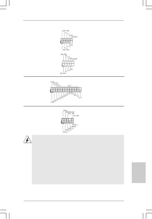
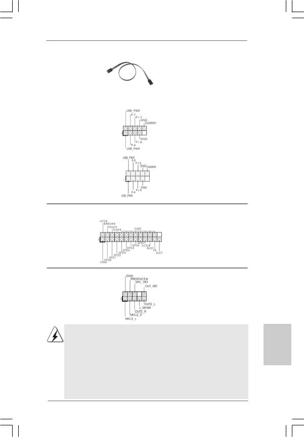
|
USB 2.0 Headers |
Besides four default USB 2.0 |
|
(9-pin USB6_7) |
ports on the I/O panel, there are |
|
(see p.2 No. 17) |
two USB 2.0 headers on this |
|
motherboard. Each USB 2.0 |
|
|
header can support two USB |
|
|
2.0 ports. |
|
|
(9-pin USB4_5) |
|
|
(see p.2 No. 15) |
|
Print Port Header |
This is an interface for print |
|
(25-pin LPT1) |
port cable that allows |
|
(see p.2 No. 25) |
convenient connection of printer |
|
devices. |
|
Front Panel Audio Header |
This is an interface for front |
|
(9-pin HD_AUDIO1) |
panel audio cable that allows |
|
(see p.2 No. 24) |
convenient connection and |
|
control of audio devices. |
1.High Definition Audio supports Jack Sensing, but the panel wire on the chassis must support HDA to function correctly. Please follow the instruction in our manual and chassis manual to install your system.
2.If you use AC’97 audio panel, please install it to the front panel audio header as below:
A.Connect Mic_IN (MIC) to MIC2_L.
B.Connect Audio_R (RIN) to OUT2_R and Audio_L (LIN) to OUT2_L.
C.Connect Ground (GND) to Ground (GND).
D.MIC_RET and OUT_RET are for HD audio panel only. You don’t need to connect them for AC’97 audio panel.
E.Enter BIOS Setup Utility. Enter Advanced Settings, and then select Chipset Configuration. Set the Front Panel Control option from [Auto] to [Enabled].
ASRock G41M-VGS3 / G41M-VS3 Motherboard
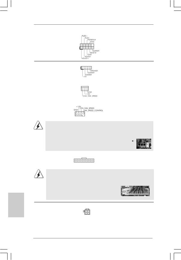
|
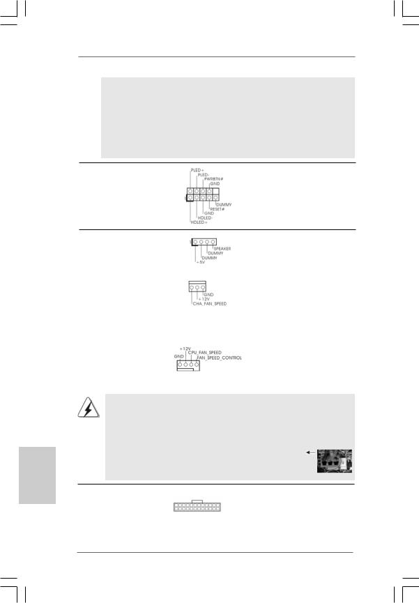
System Panel Header |
This header accommodates |
|
(9-pin PANEL1) |
several system front panel |
|
(see p.2 No. |
functions. |
English
|
Chassis Speaker Header |
Please connect the chassis |
||||
|
(4-pin SPEAKER 1) |
speaker to this header. |
||||
|
(see p.2 No. 14) |
|||||
|
Chassis Fan Connector |
Please connect a chassis fan |
||||
|
(3-pin CHA_FAN1) |
cable to this connector and |
||||
|
(see p.2 No. 16) |
match the black wire to the |
||||
|
ground pin. |
|||||
|
CPU Fan Connector |
Please connect a CPU fan cable |
||||
|
(4-pin CPU_FAN1) |
to this connector and match |
||||
|
(see p.2 No. 3) |
1 |
2 |
3 |
4 |
the black wire to the ground pin. |
Though this motherboard provides 4-Pin CPU fan (Quiet Fan) support, the 3-Pin CPU fan still can work successfully even without the fan speed control function. If you plan to connect the 3-Pin CPU fan to the CPU fan connector on this motherboard, please connect it to Pin 1-3.
|
Pin 1-3 Connected |
||||
|
3-Pin Fan Installation |
||||
|
ATX Power Connector |
24 |
13 |
Please connect an ATX power |
|
|
(24-pin ATXPWR1) |
supply to this connector. |
|||
|
12 |
1 |
|||
|
(see p.2 No. 4) |
||||
Though this motherboard provides 24-pin ATX power connector, it can still work if you adopt a traditional 20-pin ATX power supply. To use the 20-pin ATX power supply, please plug your power supply along with Pin 1 and Pin 13.
|
24 |
13 |
|
20-PinATX Power Supply Installation 12 |
1 |
|
ATX 12V Connector |
Please note that it is necessary |
|
(4-pin ATX12V2) |
to connect a power supply with |
|
(see p.2 No. 2) |
ATX 12V plug to this connector |
|
so that it can provides sufficient |
|
|
power. Failing to do so will cause |
|
|
the failure to power up. |
18
ASRock G41M-VGS3 / G41M-VS3 Motherboard
2.7 Serial ATA (SATA) / Serial ATAII (SATAII) Hard Disks Installation
This motherboard adopts Intel® ICH7 south bridge chipset that supports Serial ATA (SATA) / Serial ATAII (SATAII) hard disks. You may install SATA / SATAII hard disks on this motherboard for internal storage devices. This section will guide you to install the SATA / SATAII hard disks.
STEP 1: Install the SATA / SATAII hard disks into the drive bays of your chassis. STEP 2: Connect the SATA power cable to the SATA / SATAII hard disk.
STEP 3: Connect one end of the SATA data cable to the motherboard’s SATAII connector.
STEP 4: Connect the other end of the SATA data cable to the SATA / SATAII hard disk.
2.8 Driver Installation Guide
To install the drivers to your system, please insert the support CD to your optical drive first. Then, the drivers compatible to your system can be auto-detected and listed on the support CD driver page. Please follow the order from up to bottom side to install those required drivers. Therefore, the drivers you install can work properly.
2.9Untied Overclocking Technology
This motherboard supports Untied Overclocking Technology, which means during n overclocking, FSB enjoys better margin due to fixed PCI / PCIE buses. Before you enable Untied Overclocking function, please enter “Overclock Mode” option of BIOS setup to set the selection from [Auto] to [Manual]. Therefore, CPU FSB is untied during overclocking, but PCI / PCIE buses are in the fixed mode so that FSB can
operate under a more stable overclocking environment.
Please refer to the warning on page 8 for the possible overclocking risk before you apply Untied Overclocking Technology.
13
1
19
English
ASRock G41M-VGS3 / G41M-VS3 Motherboard

3. BIOS Information
The Flash Memory on the motherboard stores BIOS Setup Utility. When you start up the computer, please press <F2> during the Power-On-Self-Test (POST) to enter BIOS Setup utility; otherwise, POST continues with its test routines. If you wish to enter BIOS Setup after POST, please restart the system by pressing <Ctl> + <Alt> + <Delete>, or pressing the reset button on the system chassis. The BIOS Setup program is designed to be user-friendly. It is a menu-driven program, which allows you to scroll through its various sub-menus and to select among the predetermined choices. For the detailed information about BIOS Setup, please refer to the User Manual (PDF file) contained in the Support CD.
4. Software Support CD information
This motherboard supports various Microsoft® Windows® operating systems: 7 / 7 64-bit / VistaTM / VistaTM 64-bit / XP / XP 64-bit. The Support CD that came with the motherboard contains necessary drivers and useful utilities that will enhance motherboard features. To begin using the Support CD, insert the CD into your CDROM drive. It will display the Main Menu automatically if “AUTORUN” is enabled in your computer. If the Main Menu does not appear automatically, locate and doubleclick on the file “ASSETUP.EXE” from the BIN folder in the Support CD to display the menus.
English
20
ASRock G41M-VGS3 / G41M-VS3 Motherboard
![]()
1. Einführung
Wir danken Ihnen für den Kauf des ASRock G41M-VGS3 / G41M-VS3 Motherboard, ein zuverlässiges Produkt, welches unter den ständigen, strengen Qualitätskontrollen von ASRock gefertigt wurde. Es bietet Ihnen exzellente Leistung und robustes Design, gemäß der Verpflichtung von ASRock zu Qualität und Halbarkeit.
Diese Schnellinstallationsanleitung führt in das Motherboard und die schrittweise Installation ein. Details über das Motherboard finden Sie in der Bedienungsanleitung auf der Support-CD.
Da sich Motherboard-Spezifikationen und BIOS-Software verändern können, kann der Inhalt dieses Handbuches ebenfalls jederzeit geändert werden. Für den Fall, dass sich Änderungen an diesem Handbuch ergeben, wird eine neue Version auf der ASRock-Website, ohne weitere Ankündigung, verfügbar sein. Die neuesten Grafikkarten und unterstützten CPUs sind auch auf der ASRock-Website aufgelistet.
ASRock-Website: http://www.asrock.com
Wenn Sie technische Unterstützung zu Ihrem Motherboard oder spezifische Informationen zu Ihrem Modell benötigen, besuchen Sie bitte unsere Webseite:
www.asrock.com/support/index.asp
1.1 Kartoninhalt
ASRock G41M-VGS3 / G41M-VS3 Motherboard
(Micro ATX-Formfaktor: 22.6 cm x 17.0 cm; 8.9 Zoll x 6.7 Zoll) ASRock G41M-VGS3 / G41M-VS3 Schnellinstallationsanleitung ASRock G41M-VGS3 / G41M-VS3_ Support-CD
Zwei Seriell-ATA- (SATA) Datenkabel (Option) Ein I/O Shield
Deutsch
21
ASRock G41M-VGS3 / G41M-VS3 Motherboard

1.2Spezifikationen
|
Plattform |
— Micro ATX-Formfaktor: 22.6 cm x 17.0 cm; 8.9 Zoll x 6.7 Zoll |
|
CPU |
— LGA 775 für Intel® CoreTM 2 Extreme / CoreTM 2 Quad / CoreTM |
|
2 Duo / Pentium® Dual Core / Celeron® Dual Core / Celeron® |
|
|
unterstützt Penryn Quad Core Yorkfield und Dual Core |
|
|
Wolfdale Prozessoren |
|
|
— FSB1333/1066/800/533 MHz |
|
|
— Unterstützt Hyper-Threading-Technologie |
|
|
(siehe VORSICHT 1) |
|
|
— Unterstützt Untied-Übertaktungstechnologie |
|
|
(siehe VORSICHT 2) |
|
|
— Unterstützt EM64T-CPU |
|
|
Chipsatz |
— Northbridge: Intel® G41 |
|
— Southbridge: Intel® ICH7 |
|
|
Speicher |
— Unterstützung von Dual-Kanal-Speichertechnologie |
|
(siehe VORSICHT 3) |
|
|
— 2 x Steckplätze für DDR3 |
|
|
— Unterstützt DDR3 1333(OC)/1066/800 non-ECC, |
|
|
ungepufferter Speicher (siehe VORSICHT 4) |
|
|
— Max. Kapazität des Systemspeichers: 8GB |
|
|
(siehe VORSICHT 5) |
|
|
Erweiterungs- |
— 1 x PCI Express x16-Steckplätze |
|
steckplätze |
— 1 x PCI -Steckplätze |
|
Onboard-VGA |
— Intel® Graphics Media Accelerator X4500 |
|
— Pixel Shader 4.0, DX10 VGA |
|
|
— Maximal gemeinsam genutzter Speicher 1759MB |
|
|
(siehe VORSICHT 6) |
|
|
— Unterstützt D-Sub mit einer maximalen Auflösung von |
|
|
2048 x 1536 bei 75 Hz |
|
|
Audio |
— 5.1 CH HD Audio (VIA® VT1705 Audio Codec) |
|
LAN |
— G41M-VGS3 |
|
Atheros® PCIE x1 Gigabit LAN AR8131L, |
|
|
speed 10/100/1000 Mb/s |
|
|
— G41M-VS3 |
|
|
Atheros® PCIE x1 LAN AR8132L, speed 10/100 Mb/s |
|
|
— Unterstützt Wake-On-LAN |
|
|
E/A-Anschlüsse |
I/O Panel |
|
an der |
— 1 x PS/2 Mouse Port |
|
Rückseite |
— 1 x PS/2 Keyboard Port |
ASRock G41M-VGS3 / G41M-VS3 Motherboard

|
— 1 x Serieller port: COM 1 |
||
|
— 1 x VGA Port |
||
|
— 4 x Ready-to-Use USB 2.0 Ports |
||
|
— 1 x RJ-45 LAN Port mit LED (ACT/LINK LED und SPEED LED) |
||
|
— Audioanschlüsse: Line In / Line Out / Mikrofon |
||
|
Anschlüsse |
— 4 x SATAII-Anschlüsse, unterstützt bis 3.0 Gb/s |
|
|
Datenübertragungsrate (Unterstützt keine “RAID”- und “Hot- |
||
|
Plug”-Funktionen) (siehe VORSICHT 7) |
||
|
— 1 x ATA100 IDE-Anschlüsse (Unterstützt bis 2 IDE-Geräte) |
||
|
— 1 x Druckerport-Anschlussleiste |
||
|
— CPU/Gehäuse-Lüfteranschluss |
||
|
— 24-pin ATX-Netz-Header |
||
|
— 4-pin anschluss für 12V-ATX-Netzteil |
||
|
— Anschluss für Audio auf der Gehäusevorderseite |
||
|
— 2 x USB 2.0 Buchse (unterstützt 4 USB 2.0 Ports) |
||
|
(siehe VORSICHT 8) |
||
|
BIOS |
— 8Mb AMI BIOS |
|
|
— AMI legal BIOS mit Unterstützung für “Plug and Play” |
||
|
— ACPI 1.1-Weckfunktionen |
||
|
— SMBIOS 2.3.1 |
||
|
— VCCM, NB, VTT, GTLRef Stromspannung Multianpassung |
||
|
Support-CD |
— Treiber, Dienstprogramme, Antivirussoftware |
|
|
(Probeversion), ASRock-Software-Suite (CyberLink |
||
|
DVD Suite und Creative Sound Blaster X-Fi MB) (OEMund |
||
|
Testversion) |
||
|
Einzigartige |
— ASRock OC Tuner (siehe VORSICHT 9) |
|
|
Eigenschaft |
— Intelligent Energy Saver (Intelligente Energiesparfunktion) |
|
|
(siehe VORSICHT 10) |
||
|
— Sofortstart |
||
|
— ASRock Instant Flash (siehe VORSICHT 11) |
||
|
— ASRock OC DNA (siehe VORSICHT 12) |
||
|
— Hybrid Booster: |
||
|
— Schrittloser CPU-Frequenz-Kontrolle |
||
|
(siehe VORSICHT 13) |
||
|
— ASRock U-COP (siehe VORSICHT 14) |
||
|
— Boot Failure Guard (B.F.G. – Systemstartfehlerschutz) |
||
|
Hardware Monitor |
— Überwachung der CPU-Temperatur |
|
|
— Motherboardtemperaturerkennung |
||
|
— Drehzahlmessung für CPU-Lüfter |
||
|
— Drehzahlmessung für Gehäuselüfter |
||
|
— CPU-Lüftergeräuschdämpfung |
||
|
— Spannungsüberwachung: +12V, +5V, +3.3V, Vcore |
ASRock G41M-VGS3 / G41M-VS3 Motherboard
Deutsch
Betriebssysteme — Unterstützt Microsoft® Windows® 7 / 7 64-Bit / VistaTM / VistaTM 64-Bit / XP / XP 64-Bit
Zertifizierungen — FCC, CE
—Gemäß Ökodesign-Richtlinie (EuP) (Stromversorgung gemäß Ökodesign-Richtlinie (EuP) erforderlich) (siehe VORSICHT 15)
*Für die ausführliche Produktinformation, besuchen Sie bitte unsere Website: http://www.asrock.com
WARNUNG
Beachten Sie bitte, dass Overclocking, einschließlich der Einstellung im BIOS, Anwenden der Untied Overclocking-Technologie oder Verwenden von Overclocking-Werkzeugen von Dritten, mit einem gewissen Risiko behaftet ist. Overclocking kann sich nachteilig auf die Stabilität Ihres Systems auswirken oder sogar Komponenten und Geräte Ihres Systems beschädigen. Es geschieht dann auf eigene Gefahr und auf Ihre Kosten. Wir übernehmen keine Verantwortung für mögliche Schäden, die aufgrund von Overclocking verursacht wurden.
VORSICHT!
1. Die Einstellung der “Hyper-Threading Technology”, finden Sie auf Seite 33 des auf der Support-CD enthaltenen Benutzerhandbuches beschrieben.
2. Dieses Motherboard unterstützt die Untied-Übertaktungstechnologie. Unter “Entkoppelte Übertaktungstechnologie” auf Seite 19 finden Sie detaillierte Informationen.
3. Dieses Motherboard unterstützt Dual-Kanal-Speichertechnologie. Vor Implementierung der Dual-Kanal-Speichertechnologie müssen Sie die Installationsanleitung für die Speichermodule auf Seite 13 zwecks richtiger Installation gelesen haben.
4. Die unterstützten Arbeitsspeicherfrequenzen und die entsprechende CPU FSB-Frequenz entnehmen Sie bitte der nachstehenden Tabelle.
|
CPU FSB-Frequenz |
Unterstützte Arbeitsspeicherfrequenz |
|
1333 |
DDR3 800, DDR3 1066, DDR3 1333 |
|
1066 |
DDR3 800, DDR3 1066 |
|
800 |
DDR3 800 |
|
533 |
DDR3 800 |
* DDR3 1333 peichermodule werden in Übertakten Modus funktionieren. * Bei Verwendung einer FSB533-CPU auf diesem Motherboard lauft
esmit DDR3 533, wenn Sie ein DDR3 800-Speichermodul verwenden. * Wenn Sie einen FSB1333-CPU und DDR3 1333 Speichermodul
adoptieren auf dieser Hauptplatine adoptieren, müssen Sie die Steckbrücke regulieren. Bitte beziehen Sie sich auf Seite 28 für korrekte Steckbrücke Einstellungen.
24
ASRock G41M-VGS3 / G41M-VS3 Motherboard

5.Durch Betriebssystem-Einschränkungen kann die tatsächliche Speichergröße weniger als 4 GB betragen, da unter Windows® 7 / Vista™ / XP etwas Speicher zur Nutzung durch das System reserviert wird. Unter Windows® OS mit 64-Bit-CPU besteht diese Einschränkung nicht.
6.Die Maximalspeichergröße ist von den Chipshändler definiert und umgetauscht. Bitte überprüfen Sie Intel® website für die neuliche Information.
7.Vor Installation der SATAII-Festplatte an den SATAII-Anschluss lesen Sie bitte “Setup-Anleitung für SATAII-Festplatte” auf Seite 23 der “Bedienungsanleitung” auf der Support-CD, um Ihre SATAII-Festplatte dem SATAII-Modus anzugleichen. Sie können die SATA-Festplatte auch direkt mit dem SATAII-Anschluss verbinden.
8.Das Power Management für USB 2.0 arbeitet unter Microsoft® Windows® 7 64-Bit / 7 / VistaTM 64-Bit / VistaTM / XP 64-Bit / XP SP1 oder SP2 einwandfrei.
9.Es ist ein benutzerfreundlicher ASRock Übertaktenswerkzeug, das erlaubt, dass Sie Ihr System durch den Hardware-Monitor Funktion zu überblicken und Ihre Hardware-Geräte übertakten, um die beste Systemleistung unter der Windows® Umgebung zu erreichen. Besuchen Sie bitte unsere Website für die Operationsverfahren von ASRock OC Tuner. ASRock-Website: http://www.asrock.com
10.Mit einem fortschrittlichen, eigenständigen Hardund Softwaredesign nutzt der Intelligent Energy Saver eine revolutionäre Technologie, die bisher unerreichte Energieeinsparungen ermöglicht. Mit anderen Worten: Sie verbrauchen besonders wenig Energie und erreichen einen hohen Wirkungsgrad, ohne dass dies zu Lasten der Rechenleistung geht. Auf unseren Internetseiten finden Sie einige Erläuterungen zur Funktionsweise des Intelligent Energy Saver.
ASRock-Website: http://www.asrock.com
11.ASRock Instant Flash ist ein im Flash-ROM eingebettetes BIOS-Flash- Programm. Mithilfe dieses praktischen BIOS-Aktualisierungswerkzeugs können Sie das System-BIOS aktualisieren, ohne dafür zuerst Betriebssysteme wie MS-DOS oder Windows® aufrufen zu müssen. Mit diesem Programm bekommen Sie durch Drücken der <F6>-Taste während des POST-Vorgangs oder durch Drücken der <F2>-Taste im BIOS-Setup-Menü Zugang zu ASRock Instant Flash. Sie brauchen dieses Werkzeug einfach nur zu starten und die neue BIOS-Datei auf Ihrem USB-Flash-Laufwerk, Diskettenlaufwerk oder der Festplatte zu speichern, und schon können Sie Ihr BIOS mit nur wenigen Klickvorgängen ohne Bereitstellung einer zusätzlichen Diskette oder eines anderen komplizierten Flash-Programms aktualisieren. Achten Sie darauf, dass das USB-Flash-Laufwerk oder die Festplatte das Dateisystem FAT32/16/12 benutzen muss.
ASRock G41M-VGS3 / G41M-VS3 Motherboard

12.Allein der Name – OC DNA* – beschreibt es wörtlich, was die Software zu leisten vermag. OC DNA ist ein von ASRock exklusiv entwickeltes Dienstprogramm, das Nutzern eine bequeme Möglichkeit bietet, Übertaktungseinstellungen aufzuzeichnen und sie Anderen mitzuteilen. Es hilft Ihnen, Ihre Übertaktungsaufzeichnung im Betriebssystem zu speichern und vereinfacht den komplizierten Aufzeichnungsvorgang von Übertaktungseinstellungen. Mit OC DNA können Sie Ihre Übertaktungseinstellungen als Profil abspeichern und Ihren Freunden zugänglich machen! Ihre Freunde können dann das Übertaktungsprofil auf ihren eigenen Systemen laden, um dieselben Übertaktungseinstellungen. Mit OC DNA können Sie Ihre Übertaktungseinstellungen als Profil abspeichern und Ihren Freunden zugänglich machen! Ihre Freunde können dann das Übertaktungsprofil auf ihren eigenen Systemen laden, um dieselben Übertaktungseinstellungen wie Sie zu erhalten! Beachten Sie bitte, dass das Übertaktungsprofil nur bei einem identischen Motherboard gemeinsam genutzt und funktionsfähig gemacht werden kann. Übertaktungseinstellungen wie Sie zu erhalten! Beachten Sie bitte, dass das Übertaktungsprofil nur bei einem identischen Motherboard gemeinsam genutzt und funktionsfähig gemacht werden kann.
13.Obwohl dieses Motherboard stufenlose Steuerung bietet, wird Overclocking nicht empfohlen. Frequenzen, die von den empfohlenen CPU-Busfrequenzen abweichen, können Instabilität des Systems verursachen oder die CPU beschädigen.
14.Wird eine Überhitzung der CPU registriert, führt das System einen automatischen Shutdown durch. Bevor Sie das System neu starten, prüfen Sie bitte, ob der CPU-Lüfter am Motherboard richtig funktioniert, und stecken Sie bitte den Stromkabelstecker aus und dann wieder ein. Um die Wärmeableitung zu verbessern, bitte nicht vergessen, etwas Wärmeleitpaste zwischen CPU und Kühlkörper zu sprühen.
15.EuP steht für Energy Using Product und kennzeichnet die ÖkodesignRichtlinie, die von der Europäischen Gemeinschaft zur Festlegung des Energieverbrauchs von vollständigen Systemen in Kraft gesetzt wurde. Gemäß dieser Ökodesign-Richtlinie (EuP) muss der gesamte Netzstromverbrauch von vollständigen Systemen unter 1,00 Watt liegen, wenn sie ausgeschaltet sind. Um dem EuP-Standard zu entsprechen, sind ein EuP-fähiges Motherboard und eine EuP-fähige Stromversorgung erforderlich. Gemäß einer Empfehlung von Intel muss eine EuP-fähige Stromversorgung dem Standard entsprechen, was bedeutet, dass bei einem Stromverbrauch von 100 mA die 5-Volt-Standby-Energieeffizienz höher als 50% sein sollte. Für die Wahl einer EuP-fähigen Stromversorgung empfehlen wir Ihnen, weitere Details beim Hersteller der Stromversorgung abzufragen.
ASRock G41M-VGS3 / G41M-VS3 Motherboard
Hinweis:
Jumper
PS2_USB_PWR1
(siehe S.2 — No. 1)
1.3 Einstellung der Jumper
Die Abbildung verdeutlicht, wie Jumper gesetzt werden. Werden Pins durch Jumperkappen verdeckt, ist der Jumper “Gebrückt”. Werden keine Pins durch
Jumperkappen verdeckt, ist der Jumper Gebrückt Offen “Offen”. Die Abbildung zeigt einen 3-Pin
Jumper dessen Pin1 und Pin2 “Gebrückt” sind, bzw. es befindet sich eine JumperKappe auf diesen beiden Pins.
Einstellun Beschreibung
Überbrücken Sie Pin2, Pin3, um +5VSB (Standby) zu setzen und die PS/2 oder USBWeckfunktionen zu aktivieren.
Um +5VSB nutzen zu können, muss das Netzteil auf dieser Leitung 2A oder mehr leisten können.
CMOS löschen
(CLRCMOS1, 2-Pin jumper) (siehe S.2 — No. 18)
2-Pin jumper
Hinweis: Mit CLRCMOS1 können Sie die Daten im CMOS löschen. Die CMOS Daten beinhalten die Systeminformationen wie Systemkennwort, Datum, Zeit und System-Setupeinstellungen. Um die Einstellungen zu löschen und Default-Werte wiederherzustellen, schalten Sie den Computer aus, ziehen Sie den Netzstecker und überbrücken Sie 2-pin von CLRCMOS1 mithilfe des Jumpers für 5 Sekunden.
|
EUP LAN / EUP-Audio-Jumper |
||
|
(EUP_LAN1, 3-pol. Jumper, siehe Seite 2, Nr. 22) |
Standard (EuP aktivieren) |
|
|
(EUP_AUDIO1, 3-pol. Jumper, siehe Seite 2, Nr. 21) |
||
Hinweis: Das Jumper-Design EUP_LAN und EUP_AUDIO verringert den Energieverbrauch dieses Motherboards, um dem Standard der Ökodesign-Richtlinie (EuP) zu entsprechen. Mit einem ASRockMotherboard gemäß der Ökodesign-Richtlinie (EuP) und einer Stromversorgung, deren 5 VSB-Energieeffizienz der Standby-Spannung bei einer Stromaufnahme von 100 mA höher ist als 50%, ist Ihr System befähigt, sich dem Standard der Ökodesign-Richtlinie (EuP) auszusetzen. Die Standardeinstellung ist EuP-aktiviert (Pin 1 und Pin 2
27
Deutsch
ASRock G41M-VGS3 / G41M-VS3 Motherboard
sind geschlossen). Möchten Sie diese Energiesparfunktion deaktivieren, müssen Sie Pin 2 und Pin 3 schließen. Wird der EUP_LAN-Jumper auf aktiviert gesetzt, beachten Sie bitte, dass die Wake-On-LAN-Funktion bei S3 (Suspend-to-RAM), S4 (Suspend-to-Disk) und S5 (Standby) deaktiviert ist.
(EuP deaktivieren)
FSB1-Jumper
|
(FSB1, 3-pol. Jumper, siehe Seite 2, Nr. 26) |
Default-Einstellung |
Wenn Sie die FSB1333-CPU und DDR3 1333 Speicher auf diesem Motherboard übernehmen, müssen Sie Jumper umsetzen. Schliesen Sie Kontaktstift 2, Kontaktstift
3kurz für FSB1-Jumper. Andernfalls wird die CPU und Speicher auf diesem Motherboard eventuell nicht richtig funtionieren. Beachten Sie bitte dienachstehenden Jumper-Einstellungen.
Deutsch
1.4 Integrierte Header und Anschlüsse
Integrierte Header und Anschlüsse sind KEINE Jumper. Setzen Sie
KEINE Jumperkappen auf diese Header und Anschlüsse. Wenn Sie
Jumperkappen auf Header und Anschlüsse setzen, wird das
Motherboard unreparierbar beschädigt!
Primärer IDE-Anschluss (Blauer)
(39-pin IDE1, siehe S.2 — No. 9)
|
Blauer Anschluss |
Schwarzer Anschluss |
|
zum Motherboard |
zur Festplatte |
|
80-adriges ATA 66/100 Kabel |
Hinweis: Details entnehmen Sie bitte den Anweisungen Ihres IDE-Gerätehändlers.
|
Seriell-ATAII-Anschlüsse |
Diese vier Serial ATA |
|
(SATAII_1: |
(SATA II) -Anschlüsse |
|
siehe S.2, Punkt 10) |
unterstützen interne SATA- |
|
(SATAII_2: |
oder SATA II-Festplatten. Die |
|
siehe S.2, Punkt 11) SATAII_4 SATAII_3 |
SATAII_2 SATAII_1 aktuelle SATAII-Schnittstelle |
|
(SATAII_3: |
ermöglicht eine |
|
siehe S.2, Punkt 12) |
Datenübertragungsrate bis |
|
(SATAII_4: |
3,0 Gb/s. |
|
siehe S.2, Punkt 13) |
28
ASRock G41M-VGS3 / G41M-VS3 Motherboard
|
Serial ATA- (SATA-) |
Sie können beide Enden des |
|
Datenkabel |
SATA-Datenkabels entweder |
|
(Option) |
mit der SATA / SATAII- |
|
Festplatte oder |
|
|
dem SATAII-Anschluss am |
|
|
Mainboard verbinden. |
|
|
USB 2.0-Header |
Zusätzlich zu den vier |
|
(9-pol. USB6_7) |
üblichen USB 2.0-Ports an den |
|
(siehe S.2 — No. 17) |
I/O-Anschlüssen befinden sich |
|
zwei USB 2.0-Anschlussleisten |
|
|
am Motherboard. Pro USB 2.0- |
|
|
Anschlussleiste werden zwei |
|
|
(9-pol. USB4_5) |
USB 2.0-Ports unterstützt. |
|
(siehe S.2 — No. 15) |
|
Druckerport-Anschlussleiste |
Dies ist eine Schnittstelle zum |
|
(25-pol. LPT1) |
Anschluss eines Druckerport- |
|
(siehe S.2 — No. 25) |
Kabels, mit dem Sie passende |
|
Drucker auf einfache Weise |
|
|
anschließen können. |
|
Anschluss für Audio auf |
Dieses Interface zu einem |
|
|
der Gehäusevorderseite |
Audio-Panel auf der Vorderseite |
|
|
(9-Pin HD_AUDIO1) |
Ihres Gehäuses, ermöglicht |
|
|
(siehe S.2 — No. 24) |
Ihnen eine bequeme |
|
|
Anschlussmöglichkeit und |
||
|
Kontrolle über Audio-Geräte. |
||
|
1. High Definition Audio unterstützt Jack Sensing (automatische Erkennung |
Deutsch |
|
|
falsch angeschlossener Geräte), wobei jedoch die Bildschirmverdrahtung |
||
|
am Gehäuse HDA unterstützen muss, um richtig zu funktionieren. |
||
|
Beachten Sie bei der Installation im System die Anweisungen in unserem |
||
Handbuch und im Gehäusehandbuch.
2. Wenn Sie die AC’97-Audioleiste verwenden, installieren Sie diese wie nachstehend beschrieben an der Front-Audioanschlussleiste:
A. Schließen Sie Mic_IN (MIC) an MIC2_L an.
B. Schließen Sie Audio_R (RIN) an OUT2_R und Audio_L (LIN) an
OUT2_L an.
29
ASRock G41M-VGS3 / G41M-VS3 Motherboard
Obwohl dieses Motherboard einen vierpoligen CPU-Lüfteranschluss (Quiet Fan) bietet, können auch CPU-Lüfter mit dreipoligem Anschluss angeschlossen werden; auch ohne Geschwindigkeitsregulierung. Wenn Sie einen dreipoligen CPU-Lüfter an den CPU-Lüferanschluss dieses Motherboards anschließen möchten, verbinden Sie ihn bitte mit
den Pins 1 – 3. Pins 1–3 anschließen
Lüfter mit dreipoligem Anschluss installieren
C.Schließen Sie Ground (GND) an Ground (GND) an.
D.MIC_RET und OUT_RET sind nur für den HD-Audioanschluss gedacht. Diese Anschlüsse müssen nicht an die AC’97-Audioleiste angeschlossen werden.
E.Rufen Sie das BIOS-Setup-Dienstprogramm auf. Wechseln Sie zu Erweiterte Einstellungen und wählen Sie Chipset-Konfiguration. Setzen Sie die Option Frontleistenkontrolle von [Automatisch] auf [Aktiviert].
|
System Panel-Header |
Dieser Header unterstützt |
|
(9-pin PANEL1) |
mehrere Funktion der |
|
(siehe S.2 — No. |
Systemvorderseite. |
|
Gehäuselautsprecher-Header |
Schließen Sie den |
|
(4-pin SPEAKER1) |
Gehäuselautsprecher an |
|
(siehe S.2 — No. 14) |
diesen Header an. |
|
Gehäuselüfteranschluss |
Verbinden Sie das |
|
(3-pin CHA_FAN1) |
Gehäuselüfterkabel mit diesem |
|
(siehe S.2 — No. 16) |
Anschluss und passen Sie den |
|
schwarzen Draht dem |
|
|
Erdungsstift an. |
|
|
CPU-Lüfteranschluss |
Verbinden Sie das CPU — |
|
(4-pin CPU_FAN1) |
Lüfterkabel mit diesem |
|
(siehe S.2 — No. 3) |
Anschluss und passen Sie den |
|
1 2 3 4 |
schwarzen Draht dem |
|
Erdungsstift an. |
Deutsch
ATX-Netz-Header
|
24 |
13 |
|
(24-pin ATXPWR1) |
|
|
12 |
1 |
|
(siehe S.2 — No. 4) |
30
Verbinden Sie die ATXStromversorgung mit diesem Header.
ASRock G41M-VGS3 / G41M-VS3 Motherboard
![]()
n
Obwohl dieses Motherboard einen 24-pol. ATX-Stromanschluss bietet, kann es auch mit einem modifizierten traditionellen 20-pol. ATX-Netzteil verwendet werden. Um ein 20-pol. ATX-Netzteil zu verwenden, stecken Sie den Stecker mit
|
Pin 1 und Pin 13 ein. |
24 |
13 |
|
Installation eines 20-pol. ATX-Netzteils 12 |
1 |
|
|
Anschluss für |
Beachten Sie bitte, dass Sie |
|
|
12V-ATX-Netzteil |
eine Stromversorgung mit ATX |
|
|
(4-pol. ATX12V1) |
12-Volt-Stecker mit diesem |
|
|
(siehe S.2 — Nr. 2) |
Anschluss verbinden müssen, |
|
|
damit ausreichend Strom |
geliefert werden kann. Andernfalls reicht der Strom nicht aus, das System zu starten.
Deutsch
31
ASRock G41M-VGS3 / G41M-VS3 Motherboard

2. BIOS-Information
Das Flash Memory dieses Motherboards speichert das Setup-Utility. Drücken Sie <F2> während des POST (Power-On-Self-Test) um ins Setup zu gelangen, ansonsten werden die Testroutinen weiter abgearbeitet. Wenn Sie ins Setup gelangen wollen, nachdem der POST durchgeführt wurde, müssen Sie das System über die Tastenkombination <Ctrl> + <Alt> + <Delete> oder den Reset-Knopf auf der Gehäusevorderseite, neu starten. Natürlich können Sie einen Neustart auch durchführen, indem Sie das System kurz abund danach wieder anschalten.
Das Setup-Programm ist für eine bequeme Bedienung entwickelt worden. Es ist ein menügesteuertes Programm, in dem Sie durch unterschiedliche Untermenüs scrollen und die vorab festgelegten Optionen auswählen können. Für detaillierte Informationen zum BIOS-Setup, siehe bitte das Benutzerhandbuch (PDF Datei) auf der Support CD.
3. Software Support CD information
Dieses Motherboard unterstützt eine Reiche von Microsoft® Windows® Betriebssystemen: 7 / 7 64-Bit / VistaTM / VistaTM 64-Bit / XP / XP 64-Bit. Die Ihrem Motherboard beigefügte Support-CD enthält hilfreiche Software, Treiber und Hilfsprogramme, mit denen Sie die Funktionen Ihres Motherboards verbessern können Legen Sie die Support-CD zunächst in Ihr CD-ROM-Laufwerk ein. Der Willkommensbildschirm mit den Installationsmenüs der CD wird automatisch aufgerufen, wenn Sie die “Autorun”-Funktion Ihres Systems aktiviert haben. Erscheint der Wilkommensbildschirm nicht, so “doppelklicken” Sie bitte auf das File ASSETUP.EXE im BIN-Verzeichnis der Support-CD, um die Menüs aufzurufen.
Das Setup-Programm soll es Ihnen so leicht wie möglich machen. Es ist menügesteuert, d.h. Sie können in den verschiedenen Untermenüs Ihre Auswahl treffen und die Programme werden dann automatisch installiert.
Deutsch
32
ASRock G41M-VGS3 / G41M-VS3 Motherboard

1. Introduction
Merci pour votre achat d’une carte mère ASRock G41M-VGS3 / G41M-VS3, une carte mère très fiable produite selon les critères de qualité rigoureux de ASRock. Elle offre des performances excellentes et une conception robuste conformément à l’engagement d’ASRock sur la qualité et la fiabilité au long terme.
Ce Guide d’installation rapide présente la carte mère et constitue un guide d’installation pas à pas. Des informations plus détaillées concernant la carte mère pourront être trouvées dans le manuel l’utilisateur qui se trouve sur le CD d’assistance.
Les spécifications de la carte mère et le BIOS ayant pu être mis à jour, •le contenu de ce manuel est sujet à des changements sans notification. Au cas où n’importe qu’elle modification intervenait sur ce manuel, la version mise à jour serait disponible sur le site web ASRock sans nouvel avis. Vous trouverez les listes de prise en charge des cartes VGA et CPU également sur le site Web ASRock. Site web ASRock, http://www.asrock.com
Si vous avez besoin de support technique en relation avec cette carte mère, veuillez consulter notre site Web pour de plus amples informations particulières au modèle que vous utilisez. www.asrock.com/support/index.asp
1.1 Contenu du paquet
Carte mère ASRock G41M-VGS3 / G41M-VS3
(Facteur de forme Micro ATX: 8.9 pouces x 6.7 pouces, 22.6 cm x 17.0 cm) Guide d’installation rapide ASRock G41M-VGS3 / G41M-VS3
CD de soutien ASRock G41M-VGS3 / G41M-VS3
Deux câble de données Serial ATA (SATA) (en option) Un écran I/O
Français
33
ASRock G41M-VGS3 / G41M-VS3 Motherboard

Français
1.2 Spécifications
|
Format |
— Facteur de forme Micro ATX: |
||||
|
8.9 pouces x 6.7 pouces, 22.6 cm x 17.0 cm |
|||||
|
CPU |
— LGA 775 pour Intel® CoreTM 2 Extreme / CoreTM 2 Quad / |
||||
|
CoreTM 2 Duo / Pentium® Dual Core / Celeron® Dual Core / |
|||||
|
Celeron® acceptant les processeurs Penryn Quad Core |
|||||
|
Yorkfield et Dual Core Wolfdale |
|||||
|
— FSB1333/1066/800/533MHz CPUs |
|||||
|
— Prise en charge de la technologie Hyper-Threading |
|||||
|
(voir ATTENTION 1) |
|||||
|
— Prend en charge la technologie Untied Overclocking |
|||||
|
(voir ATTENTION 2) |
|||||
|
— Prise en charge de la technologie EM64T par le CPU |
|||||
|
Chipsets |
— Northbridge: Intel® G41 |
||||
|
— Southbridge: Intel® ICH7 |
|||||
|
Mémoire |
— Compatible avec la Technologie de Mémoire à Canal Double |
||||
|
(voir ATTENTION 3) |
|||||
|
— 2 x slots DIMM DDR3 |
|||||
|
— Supporter DDR3 1333(OC)/1066/800 non-ECC, sans |
|||||
|
amortissement mémoire (voir ATTENTION 4) |
|||||
|
— Capacité maxi de mémoire système: 8GB |
|||||
|
(voir ATTENTION 5) |
|||||
|
Slot d’extension |
— 1 x slot PCI Express x16 |
||||
|
— 1 x slot PCI |
|||||
|
VGA sur carte |
— Intel® Graphics Media Accelerator X4500 |
||||
|
— nuanceur de pixels 4.0, VGA DX10 |
|||||
|
— mémoire partagée max 1759MB (voir ATTENTION 6) |
|||||
|
— Prend en charge le D-Sub avec une résolution maximale |
|||||
|
jusqu’à 2048×1536 @ 75Hz |
|||||
|
Audio |
— 5.1 Son haute définition de CH (codec audio VIA® VT1705) |
||||
|
LAN |
— G41M-VGS3 |
||||
|
Atheros® PCIE x1 Gigabit LAN AR8131L, |
|||||
|
Vitesse 10/100/1000 Mb/s |
|||||
|
— G41M-VS3 |
|||||
|
Atheros® PCIE x1 LAN AR8132L, Vitesse 10/100 Mb/s |
|||||
|
— Support du Wake-On-LAN |
|||||
|
Panneau arrière |
I/O Panel |
||||
|
E/S |
— 1 x port souris PS/2 |
||||
|
— 1 x port clavier PS/2 |
|||||
|
— 1 x port série: COM 1 |
|||||
|
34 |
— 1 x port VGA |
||||
ASRock G41M-VGS3 / G41M-VS3 Motherboard

|
— 4 x ports USB 2.0 par défaut |
|
|
— 1 x port LAN RJ-45 avec LED (ACT/LED CLIGNOTANTE et |
|
|
LED VITESSE) |
|
|
— Jack audio: entrée ligne / sortie ligne / microphone |
|
|
Connecteurs |
— 4 x connecteurs SATAII, prennent en charge un taux de |
|
transfert de données pouvant aller jusqu’à 3.0Go/s |
|
|
(Ne supporte pas les fonctions “RAID” et “Hot-Plug” |
|
|
(Connexion à chaud)) (voir ATTENTION 7) |
|
|
— 1 x ATA100 IDE connecteurs |
|
|
(prend en charge jusqu’à 2 périphériques IDE) |
|
|
— 1 x embase de port d’impression |
|
|
— Connecteur pour ventilateur de CPU/Châssis |
|
|
— br. 24 connecteur d’alimentation ATX |
|
|
— br. 4 connecteur d’alimentation 12V ATX |
|
|
— Connecteur audio panneau avant |
|
|
— 2 x en-tête USB 2.0 (accepte 4 ports USB 2.0) |
|
|
(voir ATTENTION 8) |
|
|
BIOS |
— 8Mb BIOS AMI |
|
— BIOS AMI |
|
|
— Support du “Plug and Play” |
|
|
— Compatible pour événements de réveil ACPI 1.1 |
|
|
— Support SMBIOS 2.3.1 |
|
|
— VCCM, NB, VTT, GTLRef Tension Multi-ajustement |
|
|
CD d’assistance |
— Pilotes, utilitaires, logiciel anti-virus (Version d’essai), Suite |
|
logicielle ASRock (CyberLink DVD Suite et Creative Sound |
|
|
Blaster X-Fi MB) (Version OEM et d’essai) |
|
|
Caractéristique |
— Tuner ASRock OC (voir ATTENTION 9) |
|
unique |
— Économiseur d’énergie intelligent (voir ATTENTION 10) |
|
— l’Instant Boot |
|
|
— ASRock Instant Flash (voir ATTENTION 11) |
|
|
— ASRock OC DNA (voir ATTENTION 12) |
|
|
— L’accélérateur hybride: |
|
|
— Contrôle direct de la fréquence CPU |
|
|
(voir ATTENTION 13) |
|
|
— ASRock U-COP (voir ATTENTION 14) |
|
|
— Garde d’échec au démarrage (B.F.G.) |
|
|
Surveillance |
— Contrôle de la température CPU |
|
système |
— Mesure de température de la carte mère |
|
— Tachéomètre ventilateur CPU |
|
|
— Tachéomètre ventilateur châssis |
|
|
— Ventilateur silencieux d’unité centrale |
|
|
— Monitoring de la tension: +12V, +5V, +3.3V, Vcore |
ASRock G41M-VGS3 / G41M-VS3 Motherboard

Français
|
OS |
— Microsoft® Windows® 7 / 7 64-bit / VistaTM / VistaTM 64-bit / |
|
XP / XP 64-bit |
|
|
Certifications |
— FCC, CE |
—Prêt pour EuP (alimentation Prêt pour EuP requise) (voir ATTENTION 15)
*Pour de plus amples informations sur les produits, s’il vous plaît visitez notre site web: http://www.asrock.com
ATTENTION
Il est important que vous réalisiez qu’il y a un certain risque à effectuer l’overclocking, y compris ajuster les réglages du BIOS, appliquer la technologie Untied Overclocking, ou utiliser des outils de tiers pour l’overclocking. L’overclocking peut affecter la stabilité de votre système, ou même causer des dommages aux composants et dispositifs de votre système. Si vous le faites, c’est à vos frais et vos propres risques. Nous ne sommes pas responsables des dommages possibles causés par l’overclocking.
ATTENTION!
1. En ce qui concerne le paramétrage “Hyper-Threading Technology”, veuillez consulter la page 33 du manuel de l’utilisateur sur le CD technique.
2. Cette carte mère prend en charge la technologie Untied Overclocking. Veuillez lire “La technologie de surcadençage à la volée” à la page 19 pour plus d’informations.
3. Cette carte mère supporte la Technologie de Mémoire à Canal Double. Avant d’intégrer la Technologie de Mémoire à Canal Double, assurezvous de bien lire le guide d’installation des modules mémoire en page 13 pour réaliser une installation correcte.
4. Veuillez vérifier dans le tableau ci-dessous pour les fréquences de prise en charge mémoire et les fréquences FSB UC correspondantes.
|
Fréquence FSB UC |
Fréquence de prise en charge mémoire |
|
1333 |
DDR3 800, DDR3 1066, DDR3 1333 |
|
1066 |
DDR3 800, DDR3 1066 |
|
800 |
DDR3 800 |
|
533 |
DDR3 800 |
* DDR3 1333 modules de mémoire fonctionneront en mode overclocking. * Lorsque vous utilisez un processeur a FSB533 sur cette carte mere,le systeme fonctionnera a DDR3 533 si vous utilisez un module memoire
DDR3 800.
*Si vous adopter un CPU FSB1333 et module de mémoire DDR3 1333 sur cette carte mère, vous devez ajuster les cavaliers. S’il vous plaît, vous référer à la page 40 pour une bonne cavaliers.
5.Du fait des limites du système d’exploitation, la taille mémoire réelle réservée au système pourra être inférieure à 4 Go sous Windows® 7 / VistaTM / XP. Avec Windows® OS avec CPU 64 bits, il n’y a pas ce genre de limitation.
36
ASRock G41M-VGS3 / G41M-VS3 Motherboard
 Loading…
View a manual of the Asrock G41M-VS3 below. All manuals on ManualsCat.com can be viewed completely free of charge. By using the ‘Select a language’ button, you can choose the language of the manual you want to view.
Page: 1
1
1
1
1
1
G41M-VGS3 / G41M-VS3
User Manual
Version 1.0
Published December 2009
Copyright©2009 ASRock INC. All rights reserved.
Page: 2
2
2
2
2
2
Copyright Notice:
Copyright Notice:
Copyright Notice:
Copyright Notice:
Copyright Notice:
No part of this manual may be reproduced, transcribed, transmitted, or translated in
any language, in any form or by any means, except duplication of documentation by
the purchaser for backup purpose, without written consent of ASRock Inc.
Products and corporate names appearing in this manual may or may not be regis-
tered trademarks or copyrights of their respective companies, and are used only for
identification or explanation and to the owners’ benefit, without intent to infringe.
Disclaimer:
Disclaimer:
Disclaimer:
Disclaimer:
Disclaimer:
Specifications and information contained in this manual are furnished for informa-
tional use only and subject to change without notice, and should not be constructed
as a commitment by ASRock. ASRock assumes no responsibility for any errors or
omissions that may appear in this manual.
With respect to the contents of this manual, ASRock does not provide warranty of
any kind, either expressed or implied, including but not limited to the implied warran-
ties or conditions of merchantability or fitness for a particular purpose.
In no event shall ASRock, its directors, officers, employees, or agents be liable for
any indirect, special, incidental, or consequential damages (including damages for
loss of profits, loss of business, loss of data, interruption of business and the like),
even if ASRock has been advised of the possibility of such damages arising from any
defect or error in the manual or product.
This device complies with Part 15 of the FCC Rules. Operation is subject to the
following two conditions:
(1) this device may not cause harmful interference, and
(2) this device must accept any interference received, including interference that
may cause undesired operation.
CALIFORNIA, USA ONLY
The Lithium battery adopted on this motherboard contains Perchlorate, a toxic
substance controlled in Perchlorate Best Management Practices (BMP) regulations
passed by the California Legislature. When you discard the Lithium battery in
California, USA, please follow the related regulations in advance.
“Perchlorate Material-special handling may apply, see
www.dtsc.ca.gov/hazardouswaste/perchlorate”
ASRock Website: http://www.asrock.com
Page: 3
3
3
3
3
3
Contents
Contents
Contents
Contents
Contents
1 Introduction
1 Introduction
1 Introduction
1 Introduction
1 Introduction ……………………………………………
……………………………………………
……………………………………………
……………………………………………
…………………………………………… 5
5
5
5
5
1.1 Package Contents …………………………………………………. 5
1.2 Specifications ………………………………………………………. 6
1.3 Motherboard Layout (G41M-VGS3 / G41M-VS3) ……… 10
1.4 I/O Panel (G41M-VGS3) ………………………………………… 11
1.5 I/O Panel (G41M-VS3) …………………………………………… 12
2 Installation
2 Installation
2 Installation
2 Installation
2 Installation………………………………………………
………………………………………………
………………………………………………
………………………………………………
……………………………………………… 13
13
13
13
13
2.1 Screw Holes ……………………………………………………….. 13
2.2 Pre-installation Precautions ……………………………………. 13
2.3 CPU Installation …………………………………………………….. 14
2.4 Installation of Heatsink and CPU fan ……………………….. 16
2.5 Installation of Memory Modules (DIMM) ……………………. 17
2.6 Expansion Slots (PCI and PCI Express Slots) ………………… 18
2.7 Jumpers Setup …………………………………………………….. 19
2.8 Onboard Headers and Connectors ………………………… 20
2.9 SATAII Hard Disk Setup Guide ………………………………… 23
2.10 Serial ATA (SATA) / Serial ATAII (SATAII) Hard Disks
Installation ……………………………………………………………. 24
2.11 Driver Installation Guide ………………………………………. 24
2.12 Untied Overclocking Technology ……………………………. 24
3 BIOS S
3 BIOS S
3 BIOS S
3 BIOS S
3 BIOS SETUP UTILITY
ETUP UTILITY
ETUP UTILITY
ETUP UTILITY
ETUP UTILITY …………………………………….
…………………………………….
…………………………………….
…………………………………….
……………………………………. 25
25
25
25
25
3.1 Introduction ………………………………………………………….. 25
3.1.1 BIOS Menu Bar ……………………………………………. 25
3.1.2 Navigation Keys …………………………………………… 26
3.2 Main Screen…………………………………………………………. 26
3.3 OC Tweaker Screen ……………………………………………… 28
3.4 Advanced Screen ………………………………………………… 31
3.4.1 CPU Configuration ………………………………………… 32
3.4.2 Chipset Configuration …………………………………… 34
3.4.3 ACPI Configuration ……………………………………….. 40
3.4.4 Storage Configuration ………………………………….. 41
3.4.5 PCIPnP Configuration ……………………………………. 43
3.4.6 Super IO Configuration …………………………………. 44
3.4.7 USB Configuration ……………………………………….. 45
3.5 Hardware Health Event Monitoring Screen ……………… 46
3.6 Boot Screen…………………………………………………………. 47
3.6.1 Boot Settings Configuration ……………………………. 47
3.7 Security Screen …………………………………………………… 48
3.8 Exit Screen ………………………………………………………….. 49
Page: 4
4
4
4
4
4
4 Software Support
4 Software Support
4 Software Support
4 Software Support
4 Software Support …………………………………….
…………………………………….
…………………………………….
…………………………………….
……………………………………. 50
50
50
50
50
4.1 Install Operating System ……………………………………….. 50
4.2 Support CD Information …………………………………………. 50
4.2.1 Running Support CD …………………………………….. 50
4.2.2 Drivers Menu ……………………………………………….. 50
4.2.3 Utilities Menu ……………………………………………….. 50
4.2.4 Contact Information ………………………………………. 50
Page: 5
5
5
5
5
5
Chapter 1 Introduction
Chapter 1 Introduction
Chapter 1 Introduction
Chapter 1 Introduction
Chapter 1 Introduction
Thank you for purchasing ASRock G41M-VGS3 / G41M-VS3 motherboard, a reli-
able motherboard produced under ASRock’s consistently stringent quality control. It
delivers excellent performance with robust design conforming to ASRock’s commit-
ment to quality and endurance.
In this manual, chapter 1 and 2 contain introduction of the motherboard and step-by-step
guide to the hardware installation. Chapter 3 and 4 contain the configuration guide to
BIOS setup and information of the Support CD.
Because the motherboard specifications and the BIOS software might be
updated, the content of this manual will be subject to change without
notice. In case any modifications of this manual occur, the updated
version will be available on ASRock website without further notice. You
may find the latest VGA cards and CPU support lists on ASRock website
as well. ASRock website http://www.asrock.com
If you require technical support related to this motherboard, please visit
our website for specific information about the model you are using.
www.asrock.com/support/index.asp
1.1 P
1.1 P
1.1 P
1.1 P
1.1 Pack
ack
ack
ack
ackage Contents
age Contents
age Contents
age Contents
age Contents
ASRock G41M-VGS3 / G41M-VS3 Motherboard
(Micro ATX Form Factor: 8.9-in x 6.7-in, 22.6 cm x 17.0 cm)
ASRock G41M-VGS3 / G41M-VS3 Quick Installation Guide
ASRock G41M-VGS3 / G41M-VS3 Support CD
Two Serial ATA (SATA) Data Cables (Optional)
One I/O Panel Shield
Page: 6
6
6
6
6
6
1.2
1.2
1.2
1.2
1.2 Specifications
Specifications
Specifications
Specifications
Specifications
Platform — Micro ATX Form Factor: 8.9-in x 6.7-in, 22.6 cm x 17.0 cm
CPU — LGA 775 for Intel®
CoreTM
2 Extreme / CoreTM
2 Quad / CoreTM
2 Duo / Pentium®
Dual Core / Celeron®
Dual Core / Celeron®
,
supporting Penryn Quad Core Yorkfield and Dual Core
Wolfdale processors
— Supports FSB1333/1066/800/533 MHz
— Supports Hyper-Threading Technology (see CAUTION 1)
— Supports Untied Overclocking Technology (see CAUTION 2)
— Supports EM64T CPU
Chipset — Northbridge: Intel®
G41
— Southbridge: Intel®
ICH7
Memory — Dual Channel DDR3 Memory Technology (see CAUTION 3)
— 2 x DDR3 DIMM slots
— Supports DDR3 1333(OC)/1066/800 non-ECC, un-buffered
memory (see CAUTION 4)
— Max. capacity of system memory: 8GB (see CAUTION 5)
Expansion Slot — 1 x PCI Express x16 slot
— 1 x PCI slot
Graphics — Intel®
Graphics Media Accelerator X4500
— Pixel Shader 4.0, DirectX 10
— Max. shared memory 1759MB (see CAUTION 6)
— Supports D-Sub with max. resolution up to 2048×1536 @
75Hz
Audio — 5.1 CH HD Audio (VIA®
VT1705 Audio Codec)
LAN — G41M-VGS3
Atheros®
PCIE x1 Gigabit LANAR8131L,
speed 10/100/1000 Mb/s
— G41M-VS3
Atheros®
PCIE x1 LANAR8132L, speed 10/100 Mb/s
— Supports Wake-On-LAN
Rear Panel I/O I/O Panel
— 1 x PS/2 Mouse Port
— 1 x PS/2 Keyboard Port
— 1 x Serial Port: COM1
— 1 x VGA Port
— 4 x Ready-to-Use USB 2.0 Ports
— 1 x RJ-45 LAN Port with LED (ACT/LINK LED and SPEED LED)
— HD Audio Jack: Line in / Front Speaker / Microphone
Page: 7
7
7
7
7
7
Connector — 4 x SATAII 3.0 Gb/s connectors (No Support for RAID and
“Hot Plug” functions) (see CAUTION 7)
— 1 x ATA100 IDE connector (supports 2 x IDE devices)
— 1 x Print port header
— CPU/Chassis FAN connector
— 24 pin ATX power connector
— 4 pin 12V power connector
— Front panel audio connector
— 2 x USB 2.0 headers (support 4 USB 2.0 ports)
(see CAUTION 
BIOS Feature — 8Mb AMI BIOS
— AMI Legal BIOS
— Supports “Plug and Play”
— ACPI 1.1 Compliance Wake Up Events
— AMBIOS 2.3.1 Support
— VCCM, NB, VTT, GTLRef Voltage Multi-adjustment
Support CD — Drivers, Utilities, AntiVirus Software (Trial Version),
ASRock Software Suite (CyberLink DVD Suite and Creative
Sound Blaster X-Fi MB) (OEM and Trial Version)
Unique Feature — ASRock OC Tuner (see CAUTION 9)
— Intelligent Energy Saver (see CAUTION 10)
— Instant Boot
— ASRock Instant Flash (see CAUTION 11)
— ASRock OC DNA (see CAUTION 12)
— Hybrid Booster:
— CPU Frequency Stepless Control (see CAUTION 13)
— ASRock U-COP (see CAUTION 14)
— Boot Failure Guard (B.F.G.)
Hardware — CPU Temperature Sensing
Monitor — Chassis Temperature Sensing
— CPU Fan Tachometer
— Chassis Fan Tachometer
— CPU Quiet Fan
— Voltage Monitoring: +12V, +5V, +3.3V, Vcore
OS — Microsoft®
Windows®
7 / 7 64-bit / VistaTM
/ VistaTM
64-bit / XP
/ XP 64-bit compliant
Certifications — FCC, CE
— EuP Ready (EuP ready power supply is required)
(see CAUTION 15)
* For detailed product information, please visit our website: http://www.asrock.com
Page: 8
8
8
8
8
8
CAUTION!
1. About the setting of “Hyper Threading Technology”, please check page 33.
2. This motherboard supports Untied Overclocking Technology. Please read
“Untied Overclocking Technology” on page 24 for details.
3. This motherboard supports Dual Channel Memory Technology. Before you
implement Dual Channel Memory Technology, make sure to read the
installation guide of memory modules on page 17 for proper installation.
4. Please check the table below for the CPU FSB frequency and its
corresponding memory support frequency.
CPU FSB Frequency Memory Support Frequency
1333 DDR3 800, DDR3 1066, DDR3 1333
1066 DDR3 800, DDR3 1066
800 DDR3 800
533 DDR3 800
* DDR3 1333 memory modules will operate in overclocking mode.
* When you use a FSB533-CPU on this motherboard, it will run at
DDR3 533 if you adopt a DDR3 800 memory module.
* If you adopt FSB1333-CPU and DDR3 1333 memory module on this
motherboard, you need to adjust the jumper. Please refer to page 20 for
proper jumper settings.
5. Due to the operating system limitation, the actual memory size may be
less than 4GB for the reservation for system usage under Windows®
7 /
VistaTM
/ XP. For Windows®
OS with 64-bit CPU, there is no such limitation.
6. The maximum shared memory size is defined by the chipset vendor and
is subject to change. Please check Intel®
website for the latest information.
7. Before installing SATAII hard disk to SATAII connector, please read the “SATAII
Hard Disk Setup Guide” on page 23 to adjust your SATAII hard disk drive to
SATAII mode. You can also connect SATA hard disk to SATAII connector
directly.
8. Power Management for USB 2.0 works fine under Microsoft®
Windows®
7
64-bit / 7 / VistaTM
64-bit / VistaTM
/ XP 64-bit / XP SP1 or SP2.
9. It is a user-friendly ASRock overclocking tool which allows you to surveil
your system by hardware monitor function and overclock your hardware
devices to get the best system performance under Windows®
environment.
Please visit our website for the operation procedures of ASRock OC
Tuner. ASRock website: http://www.asrock.com
WARNING
Please realize that there is a certain risk involved with overclocking, including adjusting
the setting in the BIOS, applying Untied Overclocking Technology, or using the third-
party overclocking tools. Overclocking may affect your system stability, or even
cause damage to the components and devices of your system. It should be done at
your own risk and expense. We are not responsible for possible damage caused by
overclocking.
Page: 9
9
9
9
9
9
10. Featuring an advanced proprietary hardware and software design,
Intelligent Energy Saver is a revolutionary technology that delivers
unparalleled power savings. In other words, it is able to provide excep-
tional power saving and improve power efficiency without sacrificing
computing performance. Please visit our website for the operation pro-
cedures of Intelligent Energy Saver.
ASRock website: http://www.asrock.com
11. ASRock Instant Flash is a BIOS flash utility embedded in Flash ROM.
This convenient BIOS update tool allows you to update system BIOS
without entering operating systems first like MS-DOS or Windows®
. With
this utility, you can press <F6> key during the POST or press <F2> key to
BIOS setup menu to access ASRock Instant Flash. Just launch this tool
and save the new BIOS file to your USB flash drive, floppy disk or hard
drive, then you can update your BIOS only in a few clicks without prepar-
ing an additional floppy diskette or other complicated flash utility. Please
be noted that the USB flash drive or hard drive must use FAT32/16/12 file
system.
12. The software name itself – OC DNA literally tells you what it is capable of.
OC DNA, an exclusive utility developed by ASRock, provides a conve-
nient way for the user to record the OC settings and share with others. It
helps you to save your overclocking record under the operating system
and simplifies the complicated recording process of overclocking settings.
With OC DNA, you can save your OC settings as a profile and share with
your friends! Your friends then can load the OC profile to their own system
to get the same OC settings as yours! Please be noticed that the OC
profile can only be shared and worked on the same motherboard.
13. Although this motherboard offers stepless control, it is not recommended
to perform over-clocking. Frequencies other than the recommended CPU
bus frequencies may cause the instability of the system or damage the
CPU.
14. While CPU overheat is detected, the system will automatically shutdown.
Before you resume the system, please check if the CPU fan on the
motherboard functions properly and unplug the power cord, then plug it
back again. To improve heat dissipation, remember to spray thermal
grease between the CPU and the heatsink when you install the PC system.
15. EuP, stands for Energy Using Product, was a provision regulated by
European Union to define the power consumption for the completed system.
According to EuP, the total AC power of the completed system shall be
under 1.00W in off mode condition. To meet EuP standard, an EuP ready
motherboard and an EuP ready power supply are required. According to
Intel’s suggestion, the EuP ready power supply must meet the standard of
5v standby power efficiency is higher than 50% under 100 mA current
consumption. For EuP ready power supply selection, we recommend you
checking with the power supply manufacturer for more details.
Page: 10
1 0
1 0
1 0
1 0
1 0
1.3 Motherboard L
1.3 Motherboard L
1.3 Motherboard L
1.3 Motherboard L
1.3 Motherboard Layout (G41M-
ayout (G41M-
ayout (G41M-
ayout (G41M-
ayout (G41M-VGS3 / G41M-
VGS3 / G41M-
VGS3 / G41M-
VGS3 / G41M-
VGS3 / G41M-VS3)
VS3)
VS3)
VS3)
VS3)
1 PS2_USB_PWR1 Jumper 14 Chassis Speaker Header (SPEAKER1,Purple)
2 ATX 12V Connector (ATX12V2) 15 USB 2.0 Header (USB4_5, Blue)
3 CPU Fan Connector (CPU_FAN1) 16 Chassis Fan Connector (CHA_FAN1)
4 ATX Power Connector (ATXPWR1) 17 USB 2.0 Header (USB6_7, Blue)
5 2 x 240-pin DDR3 DIMM Slots 18 Clear CMOS Jumper (CLRCMOS1)
(Dual Channel: DDR3_A1, DDR3_B1; Blue) 19 BIOS SPI Chip
6 North Bridge Controller 20 PCI Slot (PCI1)
7 South Bridge Controller 21 EUP Audio Jumper (EUP_AUDIO1)
8 System Panel Header (PANEL1, Orange) 22 EUP LAN Jumper (EUP_LAN1)
9 IDE1 Connector (IDE1, Blue) 23 PCI Express x16 Slot (PCIE1)
10 Primary SATAII Connector (SATAII_1; Red) 24 Front Panel Audio Header
11 Secondary SATAII Connector (SATAII_2; Red) (HD_AUDIO1, Lime)
12 Third SATAII Connector (SATAII_3; Red) 25 Print Port Header (LPT1, Purple)
13 Fourth SATAII Connector (SATAII_4; Red) 26 FSB1 Jumper
1
PS2_USB_PWR1
IDE1
CHA_FAN1
SPEAKER1
1
HD_AUDIO1
Intel
G41
Chipset
CLRCMOS1
PANEL 1
HDLED RESET
PLED PWRBTN
1
8Mb
BIOS
1
AUDIO
CODEC
17.0cm (6.7 in)
22.6cm
(8.9
in)
ATX12V2
Super
IO
1 2 4 5
7
6
8
9
10
12
13
14 11
15
16
17
18
19
3
20
21
Intel
ICH7
FSB800
DDR3_A1
(64
bit,
240-pin
module)
FSB800
DDR3_B1
(64
bit,
240-pin
module)
SATAII_1
SATAII_2
PCIE1
LAN
PHY
USB 2.0
T: USB2
B: USB3
USB 2.0
T: USB0
B: USB1
Top:
RJ-45
PS2
Mouse
PS2
Keyboard
VGA1
Top:
Line
In
Center:
Line
Out
Bottom:
Mic
In
CPU_FAN1
1
USB6_7
PCI1
1
USB4_5
EuP
Ready
FSB1333
DDR3
1333
Dual
Channel
RoHS
CMOS
Battery
1
LPT1
22
COM1
DX10
EUP_LAN
1
EUP_AUDIO1
1
23
SATAII_3
SATAII_4
1
FSB1
24
25
26
Page: 11
1 1
1 1
1 1
1 1
1 1
1.4 I/O P
1.4 I/O P
1.4 I/O P
1.4 I/O P
1.4 I/O Panel (G41M-
anel (G41M-
anel (G41M-
anel (G41M-
anel (G41M-VGS3)
VGS3)
VGS3)
VGS3)
VGS3)
1 PS/2 Mouse Port (Green) 6 Microphone (Pink)
2 USB 2.0 Ports (USB23) 7 USB 2.0 Ports (USB01)
* 3 RJ-45 Port 8 VGAPort
4 Line In (Light Blue) 9 COM Port
5 Line Out (Lime) 10 PS/2 Keyboard Port (Purple)
1 2
4
3
5
6
7
8
9
10
To enable Multi-Streaming function, you need to connect a front panel audio cable to the front
panel audio header. After restarting your computer, you will find “VIA HD Audio Deck” tool on
your system. Please follow below instructions according to the OS you install.
For Windows®
XP / XP 64-bit OS:
Please click “VIA HD Audio Deck” icon , and click “Speaker”. Then you are allowed to
select “2 Channel” or “4 Channel”. Click “Power” to save your change.
For Windows®
7 / 7 64-bit / VistaTM
/ VistaTM
64-bit OS:
Please click “VIA HD Audio Deck” icon , and click “Advanced Options” on the left side
on the bottom. In “Advanced Options” screen, select “Independent Headphone”, and click
“OK” to save your change.
LAN Port LED Indications
Activity/Link LED SPEED LED
Status Description Status Description
Off No Activity Off 10Mbps connection
Blinking Data Activity Orange 100Mbps connection
Green 1Gbps connection
LAN Port
ACT/LINK
LED
SPEED
LED
Page: 12
1 2
1 2
1 2
1 2
1 2
1.5 I/O P
1.5 I/O P
1.5 I/O P
1.5 I/O P
1.5 I/O Panel (G41M-
anel (G41M-
anel (G41M-
anel (G41M-
anel (G41M-VS3)
VS3)
VS3)
VS3)
VS3)
1 PS/2 Mouse Port (Green) 6 Microphone (Pink)
2 USB 2.0 Ports (USB23) 7 USB 2.0 Ports (USB01)
* 3 RJ-45 Port 8 VGA Port
4 Line In (Light Blue) 9 COM Port
5 Line Out (Lime) 10 PS/2 Keyboard Port (Purple)
1 2
4
3
5
6
7
8
9
10
To enable Multi-Streaming function, you need to connect a front panel audio cable to the front
panel audio header. After restarting your computer, you will find “VIA HD Audio Deck” tool on
your system. Please follow below instructions according to the OS you install.
For Windows®
XP / XP 64-bit OS:
Please click “VIA HD Audio Deck” icon , and click “Speaker”. Then you are allowed to
select “2 Channel” or “4 Channel”. Click “Power” to save your change.
For Windows®
7 / 7 64-bit / VistaTM
/ VistaTM
64-bit OS:
Please click “VIA HD Audio Deck” icon , and click “Advanced Options” on the left side
on the bottom. In “Advanced Options” screen, select “Independent Headphone”, and click
“OK” to save your change.
LAN Port LED Indications
Activity/Link LED SPEED LED
Status Description Status Description
Off No Activity Off 10Mbps connection
Blinking Data Activity Green 100Mbps connection
LAN Port
ACT/LINK
LED
SPEED
LED
Page: 13
1 3
1 3
1 3
1 3
1 3
Chapter 2 Installation
Chapter 2 Installation
Chapter 2 Installation
Chapter 2 Installation
Chapter 2 Installation
G41M-VGS3 / G41M-VS3 is a Micro ATX form factor (8.9″ x 6.7″, 22.6 x 17.0 cm)
motherboard. Before you install the motherboard, study the configuration of your
chassis to ensure that the motherboard fits into it.
Make sure to unplug the power cord before installing or removing the
motherboard. Failure to do so may cause physical injuries to you and
damages to motherboard components.
2.1 Screw Holes
2.1 Screw Holes
2.1 Screw Holes
2.1 Screw Holes
2.1 Screw Holes
Place screws into the holes indicated by circles to secure the motherboard to the
chassis.
Do not over-tighten the screws! Doing so may damage the motherboard.
2.2 Pre-installation Precautions
2.2 Pre-installation Precautions
2.2 Pre-installation Precautions
2.2 Pre-installation Precautions
2.2 Pre-installation Precautions
Take note of the following precautions before you install motherboard components
or change any motherboard settings.
1. Unplug the power cord from the wall socket before touching any component.
2. To avoid damaging the motherboard components due to static electricity, NEVER
place your motherboard directly on the carpet or the like. Also remember to use
a grounded wrist strap or touch a safety grounded object before you handle
components.
3. Hold components by the edges and do not touch the ICs.
4. Whenever you uninstall any component, place it on a grounded antistatic pad or
in the bag that comes with the component.
Before you install or remove any component, ensure that the power is
switched off or the power cord is detached from the power supply.
Failure to do so may cause severe damage to the motherboard, peripherals,
and/or components.
Page: 14
1 4
1 4
1 4
1 4
1 4
Lift Lever Up to 90°
CPU Marked Corner
Socket Marked Corner
2.3 CPU Installation
2.3 CPU Installation
2.3 CPU Installation
2.3 CPU Installation
2.3 CPU Installation
For the installation of Intel 775-LAND CPU,
please follow the steps below.
Before you insert the 775-LAND CPU into the socket, please check if
the CPU surface is unclean or if there is any bent pin on the socket.
Do not force to insert the CPU into the socket if above situation is
found. Otherwise, the CPU will be seriously damaged.
Step 1. Open the socket:
Step 1-1. Disengaging the lever by depressing
down and out on the hook to clear
retention tab.
Step 1-2. Rotate the load lever to fully open po-
sition at approximately 135 degrees.
Step 1-3. Rotate the load plate to fully open po-
sition at approximately 100 degrees.
Step 2. Insert the 775-LAND CPU:
Step 2-1. Hold the CPU by the edges where are
marked with black lines.
Step 2-2. Orient the CPU with IHS (Integrated
Heat Sink) up. Locate Pin1 and the two
orientation key notches.
775-Pin Socket Overview
black
line
black
line
775-PinSocket
Pin1
alignment key alignment key
Pin1
orientation
key notch
orientation
key notch
775-LAND CPU
Page: 15
1 5
1 5
1 5
1 5
1 5
For proper inserting, please ensure to match the two orientation key
notches of the CPU with the two alignment keys of the socket.
Step 2-3. Carefully place the CPU into the socket
by using a purely vertical motion.
Step 2-4. Verify that the CPU is within the socket
and properly mated to the orient keys.
Step 3. Remove PnP Cap (Pick and Place Cap):
Use your left hand index finger and thumb to
support the load plate edge, engage PnP cap
with right hand thumb and peel the cap from the
socket while pressing on center of PnP cap to
assist in removal.
1. It is recommended to use the cap tab to handle and avoid kicking
off the PnP cap.
2. This cap must be placed if returning the motherboard for after
service.
Step 4. Close the socket:
Step 4-1. Rotate the load plate onto the IHS.
Step 4-2. While pressing down lightly on load
plate, engage the load lever.
Step 4-3. Secure load lever with load plate tab
under retention tab of load lever.
Page: 16
1 6
1 6
1 6
1 6
1 6
2.4
2.4
2.4
2.4
2.4 Installation of CPU Fan and Heatsink
Installation of CPU Fan and Heatsink
Installation of CPU Fan and Heatsink
Installation of CPU Fan and Heatsink
Installation of CPU Fan and Heatsink
This motherboard is equipped with 775-Pin socket that supports Intel 775-LAND CPU.
Please adopt the type of heatsink and cooling fan compliant with Intel 775-LAND CPU
to dissipate heat. Before you installed the heatsink, you need to spray thermal
interface material between the CPU and the heatsink to improve heat dissipation.
Ensure that the CPU and the heatsink are securely fastened and in good contact with
each other. Then connect the CPU fan to the CPU_FAN connector (CPU_FAN1, see
page 10, No. 3).
For proper installation, please kindly refer to the instruction manuals of
your CPU fan and heatsink.
Below is an example to illustrate the installation of the heatsink for 775-LAND CPU.
Step 1. Apply thermal interface material onto center
of IHS on the socket surface.
Step 2. Place the heatsink onto the socket. Ensure
fan cables are oriented on side closest to the
CPU fan connector on the motherboard
(CPU_FAN1, see page 10, No. 3).
Step 3. Align fasteners with the motherboard
throughholes.
Step 4. Rotate the fastener clockwise, then press
down on fastener caps with thumb to install
and lock. Repeat with remaining fasteners.
If you press down the fasteners without rotating them clockwise,
the heatsink cannot be secured on the motherboard.
Step 5. Connect fan header with the CPU fan
connector on the motherboard.
Step 6. Secure excess cable with tie-wrap to ensure
cable does not interfere with fan operation or
contact other components.
Page: 17
1 7
1 7
1 7
1 7
1 7
notch
break
notch
break
2.5 Installation of Memory Modules (DIMM)
2.5 Installation of Memory Modules (DIMM)
2.5 Installation of Memory Modules (DIMM)
2.5 Installation of Memory Modules (DIMM)
2.5 Installation of Memory Modules (DIMM)
G41M-VGS3 / G41M-VS3 motherboard provides two 240-pin DDR3 (Double Data
Rate 3) DIMM slots, and supports Dual Channel Memory Technology. For dual
channel configuration, you always need to install two identical (the same brand,
speed, size and chip-type) memory modules in the DDR3 DIMM slots to activate
Dual Channel Memory Technology. Otherwise, it will operate at single channel
mode.
1. It is not allowed to install a DDR or DDR2 memory module into
DDR3 slot;otherwise, this motherboard and DIMM may be damaged.
2. If you install only one memory module or two non-identical memory
modules, it is unable to activate the Dual Channel Memory Technology.
Installing a DIMM
Installing a DIMM
Installing a DIMM
Installing a DIMM
Installing a DIMM
Please make sure to disconnect power supply before adding or
removing DIMMs or the system components.
Step 1. Unlock a DIMM slot by pressing the retaining clips outward.
Step 2. Align a DIMM on the slot such that the notch on the DIMM matches the break
on the slot.
The DIMM only fits in one correct orientation. It will cause permanent
damage to the motherboard and the DIMM if you force the DIMM into the
slot at incorrect orientation.
Step 3. Firmly insert the DIMM into the slot until the retaining clips at both ends fully
snap back in place and the DIMM is properly seated.
Page: 18
1 8
1 8
1 8
1 8
1 8
2.6 Expansion Slots (PCI and PCI Express Slots)
2.6 Expansion Slots (PCI and PCI Express Slots)
2.6 Expansion Slots (PCI and PCI Express Slots)
2.6 Expansion Slots (PCI and PCI Express Slots)
2.6 Expansion Slots (PCI and PCI Express Slots)
There are 1 PCI slot and 1 PCI Express slot on this motherboard.
PCI slot: PCI slot is used to install expansion cards that have the 32-bit PCI
interface.
PCIE slot:
PCIE1 (PCIE x16 slot) is used for PCI Express cards with x16 lane
width graphics cards.
If you install the add-on PCI Express VGA card to PCIE1 (PCIE x16 slot),
the onboard VGA will be disabled. If you install the add-on PCI Express
VGA card to PCIE1 (PCIE x16 slot) and adjust the BIOS options “Primary
Graphics Adapter” to [Onboard] and “Share Memory” to [Auto], then the
onboard VGA will be enabled, and the primary screen will be onboard
VGA.
Installing an expansion card
Installing an expansion card
Installing an expansion card
Installing an expansion card
Installing an expansion card
Step 1. Before installing the expansion card, please make sure that the power
supply is switched off or the power cord is unplugged. Please read the
documentation of the expansion card and make necessary hardware
settings for the card before you start the installation.
Step 2. Remove the bracket facing the slot that you intend to use. Keep the screws
for later use.
Step 3. Align the card connector with the slot and press firmly until the card is
completely seated on the slot.
Step 4. Fasten the card to the chassis with screws.
Page: 19
1 9
1 9
1 9
1 9
1 9
2.7 Jumpers Setup
2.7 Jumpers Setup
2.7 Jumpers Setup
2.7 Jumpers Setup
2.7 Jumpers Setup
The illustration shows how jumpers are
setup. When the jumper cap is placed on
pins, the jumper is “Short”. If no jumper cap
is placed on pins, the jumper is “Open”. The
illustration shows a 3-pin jumper whose pin1
and pin2 are “Short” when jumper cap is
placed on these 2 pins.
Jumper Setting Description
PS2_USB_PWR1 Short pin2, pin3 to enable
(see p.10 No. 1) +5VSB (standby) for PS/2
or USB wake up events.
Note: To select +5VSB, it requires 2 Amp and higher standby current provided by
power supply.
Clear CMOS
(CLRCMOS1, 2-pin jumper)
(see p.10 No. 18)
Note: CLRCMOS1 allows you to clear the data in CMOS. The data in CMOS includes
system setup information such as system password, date, time, and system
setup parameters. To clear and reset the system parameters to default setup,
please turn off the computer and unplug the power cord from the power
supply. After waiting for 15 seconds, use a jumper cap to short 2 pins on
CLRCMOS1 for 5 seconds.
+5V
1_2
+5VSB
2_3
2-pin jumper
EUP LAN / EUPAudio Jumper
(EUP_LAN1, 3-pin jumper, see p.10 No. 22)
(EUP_AUDIO1, 3-pin jumper, see p.10 No. 21)
Note: EUP_LAN and EUP_AUDIO jumper design decreases the power consumption
of this motherboard to meet EuP standard. With an ASRock EuP ready
motherboard and a power supply that the 5VSB power efficiency is higher
than 50% under 100mA current consumption, your system is able to submit
EuP standard. The default setting (short pin1 and pin2) is EuP enabled. If you
want to disable this power saving function, you may short pin2 and pin3.
Please be noticed that when EUP_LAN jumper is set to enabled, the
Wake-On-LAN function under S3 (Suspend to RAM), S4 (Suspend to Disk),
and S5 (Soft Off) will be disabled.
EUP_LAN1
EUP_AUDIO1
EUP_LAN1
EUP_AUDIO1
Default (Enable EuP)
(Disable EuP)
Page: 20
2 0
2 0
2 0
2 0
2 0
FSB1 Jumper
(FSB1, 3-pin jumper, see p.10 No. 26)
If you adopt FSB1333-CPU and DDR3 1333 memory module on this motherboard, you
need to adjust the jumper. Please short pin2, pin3 for FSB1 jumper. Otherwise, the
CPU and memory module may not work properly on this motherboard. Please refer to
below jumper setting.
Default
FSB1
FSB1
2.8 Onboard Headers and Connectors
2.8 Onboard Headers and Connectors
2.8 Onboard Headers and Connectors
2.8 Onboard Headers and Connectors
2.8 Onboard Headers and Connectors
Onboard headers and connectors are NOT jumpers. Do NOT place
jumper caps over these headers and connectors. Placing jumper caps
over the headers and connectors will cause permanent damage of the
motherboard!
Primary IDE connector (Blue)
(39-pin IDE1, see p.10 No. 9)
Note: Please refer to the instruction of your IDE device vendor for the details.
Serial ATAII Connectors These Serial ATAII (SATAII)
(SATAII_1: connectors support SATAII
see p.10, No. 10) or SATA hard disk for internal
(SATAII_2: storage devices. The current
see p.10,No. 11) SATAII interface allows up to
(SATAII_3: 3.0 Gb/s data transfer rate.
see p.10, No. 12)
(SATAII_4:
see p.10, No. 13)
Serial ATA (SATA) Either end of the SATA data cable
Data Cable can be connected to the SATA /
(Optional) SATAII hard disk or the SATAII
connector on the motherboard.
connect the black end
to the IDE devices
connect the blue end
to the motherboard
80-conductor ATA 66/100 cable
IDE1
PIN1
SATAII_2 SATAII_1
SATAII_4 SATAII_3
Page: 21
2 1
2 1
2 1
2 1
2 1
1. High Definition Audio supports Jack Sensing, but the panel wire on
the chassis must support HDA to function correctly. Please follow the
instruction in our manual and chassis manual to install your system.
2. If you use AC’97 audio panel, please install it to the front panel audio
header as below:
A. Connect Mic_IN (MIC) to MIC2_L.
B. Connect Audio_R (RIN) to OUT2_R and Audio_L (LIN) to OUT2_L.
C. Connect Ground (GND) to Ground (GND).
D. MIC_RET and OUT_RET are for HD audio panel only. You don’t
need to connect them for AC’97 audio panel.
E. Enter BIOS Setup Utility. Enter Advanced Settings, and then select
Chipset Configuration. Set the Front Panel Control option from
[Auto] to [Enabled].
J_SENSE
OUT2_L
1
MIC_RET
PRESENCE#
GND
OUT2_R
MIC2_R
MIC2_L
OUT_RET
USB 2.0 Headers Besides four default USB 2.0
(9-pin USB6_7) ports on the I/O panel, there are
(see p.10 No. 17) two USB 2.0 headers on this
motherboard. Each USB 2.0
header can support two USB
2.0 ports.
(9-pin USB4_5)
(see p.10 No. 15)
USB_PWR
USB_PWR
P+7
P-7
P+6
P-6
GND
GND
DUMMY
1
USB_PWR
USB_PWR
P+5
P-5
P+4
P-4
GND
GND
DUMMY
1
Print Port Header This is an interface for print
(25-pin LPT1) port cable that allows
(see p.10 No. 25) convenient connection of printer
devices.
1
AFD#
ERROR#
PINIT#
GND
SLIN#
STB#
SPD0
SPD1
SPD2
SPD3
SPD4
SPD5
SPD6
SPD7
ACK#
BUSY
PE
SLCT
Front Panel Audio Header This is an interface for front
(9-pin HD_AUDIO1) panel audio cable that allows
(see p.10 No. 24) convenient connection and
control of audio devices.
Page: 22
2 2
2 2
2 2
2 2
2 2
+5V
DUMMY
DUMMY
SPEAKER
1
GND
PWRBTN#
PLED-
PLED+
DUMMY
RESET#
GND
HDLED+
HDLED-
1
System Panel Header This header accommodates
(9-pin PANEL1) several system front panel
(see p.10 No. functions.
Chassis Speaker Header Please connect the chassis
(4-pin SPEAKER 1) speaker to this header.
(see p.10 No. 14)
Chassis Fan Connector Please connect a chassis fan
(3-pin CHA_FAN1) cable to this connector and
(see p.10 No. 16) match the black wire to the
ground pin.
CPU Fan Connector Please connect a CPU fan cable
(4-pin CPU_FAN1) to this connector and match
(see p.10 No. 3) the black wire to the ground pin.
GND
+12V
CHA_FAN_SPEED
Though this motherboard provides 4-Pin CPU fan (Quiet Fan) support, the 3-Pin
CPU fan still can work successfully even without the fan speed control function.
If you plan to connect the 3-Pin CPU fan to the CPU fan connector on this
motherboard, please connect it to Pin 1-3.
3-Pin Fan Installation
Pin 1-3 Connected
GND
+12V
CPU_FAN_SPEED
FAN_SPEED_CONTROL
1 2 3 4
ATX Power Connector Please connect an ATX power
(24-pin ATXPWR1) supply to this connector.
(see p.10 No. 4)
20-Pin ATX Power Supply Installation
Though this motherboard provides 24-pin ATX power connector, it can still work
if you adopt a traditional 20-pin ATX power supply. To use the 20-pin ATX power
supply, please plug your power supply along with Pin 1 and Pin 13.
24 13
12 1
24 13
12 1
ATX 12V Connector Please note that it is necessary
(4-pin ATX12V2) to connect a power supply with
(see p.10 No. 2) ATX 12V plug to this connector
so that it can provides sufficient
power. Failing to do so will cause
the failure to power up.
Page: 23
2 3
2 3
2 3
2 3
2 3
2.9
2.9
2.9
2.9
2.9 SA
SA
SA
SA
SAT
T
T
T
TAII Hard Disk Setup Guide
AII Hard Disk Setup Guide
AII Hard Disk Setup Guide
AII Hard Disk Setup Guide
AII Hard Disk Setup Guide
Before installing SATAII hard disk to your computer, please carefully read below
SATAII hard disk setup guide. Some default setting of SATAII hard disks may not
be at SATAII mode, which operate with the best performance. In order to enable
SATAII function, please follow the below instruction with different vendors to
correctly adjust your SATAII hard disk to SATAII mode in advance; otherwise, your
SATAII hard disk may fail to run at SATAII mode.
Western Digital
If pin 5 and pin 6 are shorted, SATA 1.5Gb/s will be enabled.
On the other hand, if you want to enable SATAII 3.0Gb/s, please remove the
jumpers from pin 5 and pin 6.
SAMSUNG
If pin 3 and pin 4 are shorted, SATA 1.5Gb/s will be enabled.
On the other hand, if you want to enable SATAII 3.0Gb/s, please remove the
jumpers from pin 3 and pin 4.
HITACHI
Please use the Feature Tool, a DOS-bootable tool, for changing various ATA
features. Please visit HITACHI’s website for details:
http://www.hitachigst.com/hdd/support/download.htm
1
3
5
7
2
4
6
8
1
3
5
7
2
4
6
8
The above examples are just for your reference. For different SATAII hard
disk products of different vendors, the jumper pin setting methods may not
be the same. Please visit the vendors’ website for the updates.
Page: 24
2 4
2 4
2 4
2 4
2 4
2.10
2.10
2.10
2.10
2.10 Serial A
Serial A
Serial A
Serial A
Serial AT
T
T
T
TA (SA
A (SA
A (SA
A (SA
A (SAT
T
T
T
TA) / Serial A
A) / Serial A
A) / Serial A
A) / Serial A
A) / Serial AT
T
T
T
TAII (SA
AII (SA
AII (SA
AII (SA
AII (SAT
T
T
T
TAII) Hard Disks
AII) Hard Disks
AII) Hard Disks
AII) Hard Disks
AII) Hard Disks
Installation
Installation
Installation
Installation
Installation
This motherboard adopts Intel®
ICH7 south bridge chipset that supports Serial ATA
(SATA) / Serial ATAII (SATAII) hard disks. You may install SATA / SATAII hard disks
on this motherboard for internal storage devices. This section will guide you to
install the SATA / SATAII hard disks.
STEP1: Install the SATA / SATAII hard disks into the drive bays of your chassis.
STEP2: Connect the SATA power cable to the SATA / SATAII hard disk.
STEP3: Connect one end of the SATA data cable to the motherboard’s SATAII
connector.
STEP4: Connect the other end of the SATA data cable to the SATA / SATAII hard
disk.
2.11
2.11
2.11
2.11
2.11 Driver Installation Guide
Driver Installation Guide
Driver Installation Guide
Driver Installation Guide
Driver Installation Guide
To install the drivers to your system, please insert the support CD to your optical drive
first. Then, the drivers compatible to your system can be auto-detected and listed on
the support CD driver page. Please follow the order from up to bottom side to install
those required drivers. Therefore, the drivers you install can work properly.
2.12
2.12
2.12
2.12
2.12 Untied Overclocking T
Untied Overclocking T
Untied Overclocking T
Untied Overclocking T
Untied Overclocking Technology
echnology
echnology
echnology
echnology
This motherboard supports Untied Overclocking Technology, which means during
overclocking, FSB enjoys better margin due to fixed PCI / PCIE buses. Before you
enable Untied Overclocking function, please enter “Overclock Mode” option of
BIOS setup to set the selection from [Auto] to [Manual]. Therefore, CPU FSB is
untied during overclocking, but PCI / PCIE buses are in the fixed mode so that FSB
can operate under a more stable overclocking environment.
Please refer to the warning on page 8 for the possible overclocking risk
before you apply Untied Overclocking Technology.
Page: 25
2 5
2 5
2 5
2 5
2 5
Chapter 3 BIOS SETUP UTILITY
Chapter 3 BIOS SETUP UTILITY
Chapter 3 BIOS SETUP UTILITY
Chapter 3 BIOS SETUP UTILITY
Chapter 3 BIOS SETUP UTILITY
3.1 Introduction
3.1 Introduction
3.1 Introduction
3.1 Introduction
3.1 Introduction
This section explains how to use the BIOS SETUP UTILITY to configure your system.
The SPI Memory on the motherboard stores the BIOS SETUP UTILITY. You may run
the BIOS SETUP UTILITY when you start up the computer. Please press <F2> or
<Del> during the Power-On-Self-Test (POST) to enter the BIOS SETUP UTILITY,
otherwise, POST will continue with its test routines.
If you wish to enter the BIOS SETUP UTILITY after POST, restart the system by
pressing <Ctl> + <Alt> + <Delete>, or by pressing the reset button on the system
chassis. You may also restart by turning the system off and then back on.
Because the BIOS software is constantly being updated, the following
BIOS setup screens and descriptions are for reference purpose only,
and they may not exactly match what you see on your screen.
3.1.1
3.1.1
3.1.1
3.1.1
3.1.1 BIOS Menu Bar
BIOS Menu Bar
BIOS Menu Bar
BIOS Menu Bar
BIOS Menu Bar
The top of the screen has a menu bar with the following selections:
Main To set up the system time/date information
OC Tweaker To set up overclocking features
Advanced To set up the advanced BIOS features
H/W Monitor To display current hardware status
Boot To set up the default system device to locate and load the
Operating System
Security To set up the security features
Exit To exit the current screen or the BIOS SETUP UTILITY
Use < > key or < > key to choose among the selections on the menu bar,
and then press <Enter> to get into the sub screen.
Page: 26
2 6
2 6
2 6
2 6
2 6
3.1.2
3.1.2
3.1.2
3.1.2
3.1.2 Navigation Keys
Navigation Keys
Navigation Keys
Navigation Keys
Navigation Keys
Please check the following table for the function description of each navigation
key.
Navigation Key(s) Function Description
/ Moves cursor left or right to select Screens
/ Moves cursor up or down to select items
+ / — To change option for the selected items
<Enter> To bring up the selected screen
<F1> To display the General Help Screen
<F9> To load optimal default values for all the settings
<F10> To save changes and exit the BIOS SETUP UTILITY
<ESC> To jump to the Exit Screen or exit the current screen
3.2
3.2
3.2
3.2
3.2 Main Screen
Main Screen
Main Screen
Main Screen
Main Screen
When you enter the BIOS SETUP UTILITY, the Main screen will appear and display
the system overview
G41M-VGS3
System Time [Hour:Minute:Second]
Use this item to specify the system time.
System Date [Day Month/Date/Year]
Use this item to specify the system date.
BIOS SETUP UTILITY
Main OC Tweaker H/W Monitor Boot Security Exit
Advanced
System Overview
System Time
System Date
[ :00:09]
[Fri 12/18/2009]
Use [Enter], [TAB]
or [SHIFT-TAB] to
select a field.
Use [+] or [-] to
configure system Time.
Select Screen
Select Item
+- Change Field
Tab Select Field
F1 General Help
F9 Load Defaults
F10 Save and Exit
ESC Exit
v02.54 (C) Copyright 1985-2005, American Megatrends, Inc.
14
BIOS Version
Processor Type
Processor Speed
Microcode Update
Cache Size
Total Memory
DDR3_1
DDR3_2
: G41M-VGS3 P1.00
: Intel (R) Core (TM) 2 Duo CPU
E6850 @ 3.00GHz (64bit)
: 3148MHz
: 6FB/B6
: 1024KB
: 1024MB with 128MB shared memory
and 2MB GTT memory
Single-Channel Memory Mode
: 1024MB/400MHz DDR3_800
: None
Page: 27
2 7
2 7
2 7
2 7
2 7
G41M-VS3
System Time [Hour:Minute:Second]
Use this item to specify the system time.
System Date [Day Month/Date/Year]
Use this item to specify the system date.
BIOS SETUP UTILITY
Main OC Tweaker H/W Monitor Boot Security Exit
Advanced
System Overview
System Time
System Date
[ :00:09]
[Fri 12/18/2009]
Use [Enter], [TAB]
or [SHIFT-TAB] to
select a field.
Use [+] or [-] to
configure system Time.
Select Screen
Select Item
+- Change Field
Tab Select Field
F1 General Help
F9 Load Defaults
F10 Save and Exit
ESC Exit
v02.54 (C) Copyright 1985-2005, American Megatrends, Inc.
14
BIOS Version
Processor Type
Processor Speed
Microcode Update
Cache Size
Total Memory
DDR3_1
DDR3_2
: G41M-VS3 P1.00
: Intel (R) Core (TM) 2 Duo CPU
E6850 @ 3.00GHz (64bit)
: 3148MHz
: 6FB/B6
: 1024KB
: 1024MB with 128MB shared memory
and 2MB GTT memory
Single-Channel Memory Mode
: 1024MB/400MHz DDR3_800
: None
Page: 28
2 8
2 8
2 8
2 8
2 8
BIOS SETUP UTILITY
Main Advanced H/W Monitor Boot Security Exit
Select Screen
Select Item
Enter Go to Sub Screen
F1 General Help
F9 Load Defaults
F10 Save and Exit
ESC Exit
v02.54 (C) Copyright 1985-2005, American Megatrends, Inc.
OC Tweaker
OC Tweaker Settings
DRAM Timing Configuration
DRAM Command Rate [Auto]
DRAM Voltage
NB Voltage
VTT Voltage
GTLRef Voltage
[Auto]
[Auto]
[Auto]
[Auto]
DRAM Frequency [Auto]
Ratio CMOS Setting
Intel (R) SpeedStep ™ tech.
Overclock Mode
[9]
[Auto]
[Auto]
9
CPU Frequency (MHz)
PCIE Frequency (MHz)
[133]
[100]
1.60V
1.23V
1.20V
0.63Vtt
Would you like to save current setting as
DRAM Frequency
If [Auto] is selected, the motherboard will detect the memory module(s)
inserted and assigns appropriate frequency automatically. You may select
[400MHz DDR3_800], [533MHz DDR3_1066] or [667MHz DDR3_1333]. The
configuration options depend on the CPU and memory module you adopt on
this motherboard. Please refer to page 8 for the CPU FSB frequency and its
corresponding memory support frequency.
DRAM Command Rate
Use this item to adjust DRAM Command Rate. Configurationoptions: [1N],
[2N] and [Auto].
3.3
3.3
3.3
3.3
3.3 OC T
OC T
OC T
OC T
OC Tweak
weak
weak
weak
weaker Screen
er Screen
er Screen
er Screen
er Screen
In the OC Tweaker screen, you can set up overclocking features.
Page: 29
2 9
2 9
2 9
2 9
2 9
BIOS SETUP UTILITY
DRAM Timing Control
Select Screen
Select Item
+- Change Option
F1 General Help
F9 Load Defaults
F10 Save and Exit
ESC Exit
v02.54 (C) Copyright 1985-2003, American Megatrends, Inc.
OC Tweaker
Select Screen
Select Item
+- Change Option
F1 General Help
F9 Load Defaults
F10 Save and Exit
ESC Exit
DRAM tCL [Auto]
6
6
6
15
44
6
4
3
4
DRAM tRCD
DRAM tRP
DRAM tRAS
DRAM tRFC
DRAM tWR
DRAM tWTR
DRAM tRRD
DRAM tRTP
[Auto]
[Auto]
[Auto]
[Auto]
[Auto]
[Auto]
[Auto]
[Auto]
DRAM tCL
Value
Min = 5
Max = 10
DRAM Timing Configuration
DRAM tCL
This controls the number of DRAM clocks for TCL. Min: 5. Max: 10. The
default value is [Auto].
DRAM tRCD
This controls the number of DRAM clocks for TRCD. Min: 3. Max: 10. The
default value is [Auto].
DRAM tRP
This controls the number of DRAM clocks for TRP. Min: 3. Max: 10. The
default value is [Auto].
DRAM tRAS
This controls the number of DRAM clocks for TRAS. Min: 9. Max: 24. The
default value is [Auto].
DRAM tRFC
This controls the number of DRAM clocks for TRFC. Min: 15. Max: 78. The
default value is [Auto].
DRAM tWR
This controls the number of DRAM clocks for TWR. Min: 3. Max: 15. The
default value is [Auto].
DRAM tWTR
This controls the number of DRAM clocks for TWTR. Min: 2. Max: 15. The
default value is [Auto].
DRAM tRRD
This controls the number of DRAM clocks for TRRD. Min: 2. Max: 15. The
default value is [Auto].
DRAM tRTP
This controls the number of DRAM clocks for TRTP. Min: 2. Max: 13. The
default value is [Auto].
Page: 30
3 0
3 0
3 0
3 0
3 0
Ratio CMOS Setting
If the ratio status is unlocked, you will find this item appear to allow you
changing the ratio value of this motherboard. If the CPU you adopt supports
EIST (Intel (R) SpeedStep(tm) tech.), and you plan to adjust the ratio value,
please disable the option “ Intel (R) SpeedStep(tm) tech.” in advance.
Intel (R) SpeedStep(tm) tech.
Intel (R) SpeedStep(tm) tech. is Intel’s new power saving technology.
Processor can switch between multiple frequency and voltage points to
enable power savings. The default value is [Auto]. Configuration options:
[Auto], [Enabled] and [Disabled]. If you install Windows®
XP and select
[Auto], you need to set the “Power Schemes” as “Portable/Laptop” to en-
able this function. If you install Windows®
VistaTM
and want to enable this
function, please set this item to [Enabled]. This item will be hidden if the
current CPU does not support Intel (R) SpeedStep(tm) tech..
Please note that enabling this function may reduce CPU voltage and lead to system
stability or compatibility issue with some power supplies. Please set this item to
[Disable] if above issue occurs.
Overclock Mode
Use this to select Overclock Mode. The default value is [Auto]. Cnfiguration
options: [Auto], [Manual] and [Optimized].
CPU Frequency (MHz)
Use this option to adjust CPU frequency.
PCIE Frequency (MHz)
Use this option to adjust PCIE frequency.
DRAM Voltage
Use this to select DRAM Voltage. Configuration options: [Auto], [1.30V] to
[2.05V]. The default value of this feature is [Auto].
NB Voltage
Use this to select NB Voltage. Configuration options: [Auto], [1.05V] to
[1.30V]. The default value of this feature is [Auto].
VTT Voltage
Use this to select VTT Voltage. Configuration options: [Auto], [1.10V] to
[1.20V]. The default value of this feature is [Auto].
GLTREF Voltage
Use this to select GLTREF Voltage. Configuration options: [Auto],
[0.67 x Vtt], [0.65 x Vtt], [0.63 x Vtt] and [0.615 x Vtt]. The default value of
this feature is [Auto].
Would you like to save current setting user defaults?
In this option, you are allowed to load and save three user defaults
according to your own requirements.
Page: 31
3 1
3 1
3 1
3 1
3 1
BIOS SETUP UTILITY
Main OC Tweaker H/W Monitor Boot Security Exit
Select Screen
Select Item
Enter Go to Sub Screen
F1 General Help
F9 Load Defaults
F10 Save and Exit
ESC Exit
v02.54 (C) Copyright 1985-2005, American Megatrends, Inc.
Advanced
Advanced Settings
WARNING : Setting wrong values in below sections
may cause system to malfunction.
CPU Configuration
ACPI Configuration
Chipset Configuration
Storage Configuration
PCIPnP Configuration
SuperIO Configuration
USB Configuration
Options for CPU
BIOS Update Utility
ASRock Instant Flash
3.4
3.4
3.4
3.4
3.4 Advanced Screen
Advanced Screen
Advanced Screen
Advanced Screen
Advanced Screen
In this section, you may set the configurations for the following items: CPU
Configuration, Chipset Configuration,ACPI Configuration, Storage Configuration, PCIPnP
Configuration, SuperIO Configuration, and USB Configuration.
Setting wrong values in this section may cause
the system to malfunction.
Page: 32
3 2
3 2
3 2
3 2
3 2
BIOS SETUP UTILITY
CPU Configuration This should be enabled
in order to enable or
disable the “Enhanced
Halt State”.
Select Screen
Select Item
+- Change Option
F1 General Help
F9 Load Defaults
F10 Save and Exit
ESC Exit
v02.54 (C) Copyright 1985-2005, American Megatrends, Inc.
Advanced
Overclock Mode [Auto]
Select Screen
Select Item
+- Change Option
F1 General Help
F9 Load Defaults
F10 Save and Exit
ESC Exit
Enhanced Halt State
Intel (R) Virtualization tech.
Intel (R) SpeedStep ™ tech.
On-Demand Clock Mudulation
CPU Thermal Throttling
No-Execute Memory Protection
CPU Frequency (MHz)
PCIE Frequency (MHz)
[133]
[100]
Boot Failure Guard
Spread Spectrum
[Enabled]
[Auto]
Ratio CMOS Setting [9]
9
[Disabled]
[Enabled]
[Enabled]
[Disabled]
[Disabled]
[Auto]
Overclock Mode
Use this to select Overclock Mode. The default value is [Auto]. Cnfiguration
options: [Auto], [Manual] and [Optimized].
CPU Frequency (MHz)
Use this option to adjust CPU frequency.
PCIE Frequency (MHz)
Use this option to adjust PCIE frequency.
Boot Failure Guard
Enable or disable the feature of Boot Failure Guard.
Spread Spectrum
This item should always be [Auto] for better system stability.
Ratio CMOS Setting
If the ratio status is unlocked, you will find this item appear to allow you
changing the ratio value of this motherboard. If the CPU you adopt supports
EIST (Intel (R) SpeedStep(tm) tech.), and you plan to adjust the ratio value,
please disable the option “ Intel (R) SpeedStep(tm) tech.” in advance.
Enhance Halt State
All processors support the Halt State (C1). The C1 state is supported
through the native processor instructions HLT and MWAIT and requires no
hardware support from the chipset. In the C1 power state, the processor
maintains the context of the system caches.
Intel (R) Virtualization tech.
When this option is set to [Enabled], a VMM (Virtual Machine Architecture)
can utilize the additional hardware capabilities provided by Vanderpool
Technology. This option will be hidden if the installed CPU does not support
Intel (R) Virtualization Technology.
3.4.1
3.4.1
3.4.1
3.4.1
3.4.1 CPU Configuration
CPU Configuration
CPU Configuration
CPU Configuration
CPU Configuration
Page: 33
3 3
3 3
3 3
3 3
3 3
CPU Thermal Throttling
You may select [Enabled] to enable P4 CPU internal thermal control mecha-
nism to keep the CPU from overheated. This option will be hidden if the
current CPU does not support CPU Thermal Throttling.
No-Excute Memory Protection
No-Execution (NX) Memory Protection Technology is an enhancement to
the IA-32 Intel Architecture. An IA-32 processor with “No Execute (NX)
Memory Protection” can prevent data pages from being used by malicious
software to execute code. This option will be hidden if the current CPU
does not support No-Excute Memory Protection.
Hyper Threading Technology
To enable this feature, it requires a computer system with an Intel Pentium®
4 processor that supports Hyper-Threading technology and an operating
system that includes optimization for this technology, such as Microsoft®
Windows®
XP. Set to [Enabled] if using Microsoft®
Windows®
XP, or Linux
kernel version 2.4.18 or higher. This option will be hidden if the installed
CPU does not support Hyper-Threading technology.
Intel (R) SpeedStep(tm) tech.
Intel (R) SpeedStep(tm) tech. is Intel’s new power saving technology.
Processor can switch between multiple frequency and voltage points to
enable power savings. The default value is [Auto]. Configuration options:
[Auto], [Enabled] and [Disabled]. If you install Windows®
XP and select
[Auto], you need to set the “Power Schemes” as “Portable/Laptop” to en-
able this function. If you install Windows®
VistaTM
and want to enable this
function, please set this item to [Enabled]. This item will be hidden if the
current CPU does not support Intel (R) SpeedStep(tm) tech..
On-Demand Clock Modulation
This provides the On-Demand Clock Modulation duty cycle. It indicates the
clock on to clock off interval ratio. For example, if you set this option to
[75.0% On], your processor will work normally 75% of the time, and spend
the other 25% slacking off. Configuration options: [Auto], [Disabled],
[12.5% On], [25.0% On], [37.5% On], [50.0% On], [62.5% On], [75.0% On]
and [87.5% On]. The default value is [Auto].
Please note that enabling this function may reduce CPU voltage and lead to system
stability or compatibility issue with some power supplies. Please set this item to
[Disable] if above issue occurs.
Page: 34
3 4
3 4
3 4
3 4
3 4
DRAM RCOMP and tRD Configuration
BIOS SETUP UTILITY
DRAM RCOMP STRENGTH Settings
Select Screen
Select Item
+- Change Option
F1 General Help
F9 Load Defaults
F10 Save and Exit
ESC Exit
v02.54 (C) Copyright 1985-2005, American Megatrends, Inc.
Advanced
Select Screen
Select Item
+- Change Option
F1 General Help
F9 Load Defaults
F10 Save and Exit
ESC Exit
DRAM CH0 RCOMP ODT
Value
Min = 1
Max = 63
DRAM CH0 RCOMP ODT [Auto]
DRAM CH0 G0 (Data)
DRAM CH0 G1 (Command)
DRAM CH0 G2 (Control1)
DRAM CH0 G3 (Control2)
DRAM CH0 G4 (Clocks1)
DRAM CH0 G5 (Clocks2)
[Auto]
[Auto]
[Auto]
[Auto]
[Auto]
[Auto]
DRAM CH0 RCOMP STRENGTH Info : 54-0-11-6-6-6-6
DRAM CH1 RCOMP ODT
DRAM CH1 G0 (Data)
DRAM CH1 G1 (Command)
DRAM CH1 G2 (Control1)
DRAM CH1 G3 (Control2)
DRAM CH1 G4 (Clocks1)
DRAM CH1 G5 (Clocks2)
[Auto]
[Auto]
[Auto]
[Auto]
[Auto]
[Auto]
[Auto]
DRAM CH1 RCOMP STRENGTH Info : 54-0-8-8-0-8-0
DRAM CH0 RCOMP ODT
This controls the number of DRAM CH0 RCOMP ODT. Min: 1. Max: 63. The
default value is [Auto].
DRAM CH0 G0 (Data)
This controls the number of DRAM CH0 G0 (Data). Min: 1. Max: 15. The
default value is [Auto].
DRAM CH0 G1 (Command)
This controls the number of DRAM CH0 G1 (Command). Min: 1. Max: 15. The
default value is [Auto].
DRAM CH0 G2 (Control1)
This controls the number of DRAM CH0 G2 (Control1). Min: 1. Max: 15. The
default value is [Auto].
3.4.2
3.4.2
3.4.2
3.4.2
3.4.2 Chipset Configuration
Chipset Configuration
Chipset Configuration
Chipset Configuration
Chipset Configuration
BIOS SETUP UTILITY
v02.54 (C) Copyright 1985-2005, American Megatrends, Inc.
Chipset Settings
DRAM RCOMP and tRD Configuration
Fixed Mode Operation
Intelligent Energy Saver
Primary Graphics Adapter
Shared Memory
PAVP Mode
DVMT Mode Select
DVMT/FIXED Memory
Onboard HD Audio
Front Panel
OnBoard Lan
[Enabled]
[Disabled]
[Auto]
[PCI]
[Auto]
[Disabled]
[DVMT Mode]
[Maximum DVMT]
[Enabled]
[Enabled]
Select Screen
Select Item
+ — Change Option
F1 General Help
F10 Save and Exit
ESC Exit
F9 Load Defaults
Advanced
DRAM DLL SKEW Configuration
Page: 35
3 5
3 5
3 5
3 5
3 5
DRAM CH0 G3 (Control2)
This controls the number of DRAM CH0 G3 (Control2). Min: 1. Max: 15. The
default value is [Auto].
DRAM CH0 G4 (Clocks1)
This controls the number of DRAM CH0 G4 (Clocks1). Min: 1. Max: 15. The
default value is [Auto].
DRAM CH0 G5 (Clocks2)
This controls the number of DRAM CH0 G5 (Clocks2). Min: 1. Max: 15. The
default value is [Auto].
DRAM CH1 RCOMP ODT
This controls the number of DRAM CH1 RCOMP ODT. Min: 1. Max: 63. The
default value is [Auto].
DRAM CH1 G0 (Data)
This controls the number of DRAM CH1 G0 (Data). Min: 1. Max: 15. The
default value is [Auto].
DRAM CH1 G1 (Command)
This controls the number of DRAM CH1 G1 (Command). Min: 1. Max: 15. The
default value is [Auto].
DRAM CH1 G2 (Control1)
This controls the number of DRAM CH1 G2 (Control1). Min: 1. Max: 15. The
default value is [Auto].
DRAM CH1 G3 (Control2)
This controls the number of DRAM CH1 G3 (Control2). Min: 1. Max: 15. The
default value is [Auto].
DRAM CH1 G4 (Clocks1)
This controls the number of DRAM CH1 G4 (Clocks1). Min: 1. Max: 15. The
default value is [Auto].
DRAM CH1 G5 (Clocks2)
This controls the number of DRAM CH1 G5 (Clocks2). Min: 1. Max: 15. The
default value is [Auto].
DRAM CH0 tRD
This controls the number of DRAM CH0 tRD. Min: 0. Max: 30. The default
value is [Auto].
DRAM CH1 tRD
This controls the number of DRAM CH1 tRD. Min: 0. Max: 30. The default
value is [Auto].
Page: 36
3 6
3 6
3 6
3 6
3 6
DRAM DLL SKEW Configuration
BIOS SETUP UTILITY
DRAM DLL SKEW Settings
Select Screen
Select Item
+- Change Option
F1 General Help
F9 Load Defaults
F10 Save and Exit
ESC Exit
v02.54 (C) Copyright 1985-2005, American Megatrends, Inc.
Advanced
Select Screen
Select Item
+- Change Option
F1 General Help
F9 Load Defaults
F10 Save and Exit
ESC Exit
DRAM CH0 CLKSET0 SKEW [Auto]
DRAM CH0 CLKSET0 SKEW Info:0-0-0-0-0-0
DRAM CH0 CLKSET1 SKEW [Auto]
DRAM CH0 CLKSET1 SKEW Info:0-0-0-0-0-0
DRAM CH0 CMD SKEW [Auto]
DRAM CH0 CMD SKEW Info :0-0-0-0-0-0-0
DRAM CH0 CTRL0 SKEW [Auto]
DRAM CH0 CTRL0 SKEW Info :0-0-0-0-0-0-0
DRAM CH0 CTRL1 SKEW [Auto]
DRAM CH0 CTRL1 SKEW Info :0-0-0-0-0-0-0
DRAM CH0 CTRL2 SKEW [Auto]
DRAM CH0 CTRL2 SKEW Info :0-0-0-0-0-0-0
DRAM CH0 CTRL3 SKEW [Auto]
DRAM CH0 CTRL3 SKEW Info :0-0-0-0-0-0-0
DRAM CH1 CLKSET0 SKEW Info:1-5-1-1-0-128
DRAM CH0 CLKSET0 SKEW
This controls the number of DRAM CH0 CLKSET0 SKEW. The default value
is [Auto].
DRAM CH0 CLKSET1 SKEW
This controls the number of DRAM CH0 CLKSET1 SKEW. The default value
is [Auto].
DRAM CH0 CMD SKEW
This controls the number of DRAM CH0 CMD SKEW. The default value is
[Auto].
DRAM CH0 CTRL0 SKEW
This controls the number of DRAM CH0 CTRL0 SKEW. The default value is
[Auto].
DRAM CH0 CTRL1 SKEW
This controls the number of DRAM CH0 CTRL1 SKEW. The default value is
[Auto].
DRAM CH0 CTRL2 SKEW
This controls the number of DRAM CH0 CTRL2 SKEW. The default value is
[Auto].
DRAM CH0 CTRL3 SKEW
This controls the number of DRAM CH0 CTRL3 SKEW. The default value is
[Auto].
DRAM CH1 CLKSET0 SKEW
This controls the number of DRAM CH1 CLKSET0 SKEW. The default value
is [Auto].
DRAM CH1 CLKSET1 SKEW
This controls the number of DRAM CH1 CLKSET1 SKEW. The default value
is [Auto].
Page: 37
3 7
3 7
3 7
3 7
3 7
DRAM CH1 CMD SKEW
This controls the number of DRAM CH1 CMD SKEW. The default value is
[Auto].
DRAM CH1 CTRL0 SKEW
This controls the number of DRAM CH1 CTRL0 SKEW. The default value is
[Auto].
DRAM CH1 CTRL1 SKEW
This controls the number of DRAM CH1 CTRL1 SKEW. The default value is
[Auto].
DRAM CH1 CTRL2 SKEW
This controls the number of DRAM CH1 CTRL2 SKEW. The default value is
[Auto].
DRAM CH1 CTRL3 SKEW
This controls the number of DRAM CH1 CTRL3 SKEW. The default value is
[Auto].
Page: 38
3 8
3 8
3 8
3 8
3 8
Flex Mode Operation
This allows you to enable or disable flex mode operation feature. The
default value is [Enabled]. Configuration options: [Enabled] and [Disabled].
Intelligent Energy Saver
Intelligent Energy Saver is a revolutionary technology that delivers
unparalleled power savings. The default value is [Disabled]. Configuration
options: [Enabled] and [Disabled]. If you want to enable this function, please
set this item to [Enabled]. Besides the BIOS option, you can also choose our
Intelligent Energy Saver utility to enable this function.
Primary Graphics Adapter
This allows you to select [Onboard], [PCI] or [PCI Express] as the boot
graphic adapter priority. The default value is [PCI].
Share Memory
This allows you to set share memory feature. The default value is [Auto].
Configuration options: [Auto], [32MB], [64MB], [128MB] and [256MB].
PAVP Mode
Use this option to adjust PAVP mode. Configuration options: [Disabled] and
[Lite]. The default value is [Disabled]. PAVP is the new graphics feature in
Intel®
4 Series Express chipset family to support increased content
protection and robustness requirements for premium content playback (Blu-
ray disc). [Lite] mode is the encryption of compressed video buffer and is
hardware-based 128-bit AES decryption.
DVMT Mode Select
Use this option to adjust DVMT mode. The default value is [DVMT Mode].
DVMT (Dynamic Video Memory Technology) is an architecture that offers
breakthrough performance for the motherboard through efficient memory
utilization. In DVMT mode, the graphics driver allocates memory as needed
for running graphics applications and is cooperatively using this memory
with other system components. This item will not be used under Windows®
VistaTM
OS because the driver will intelligently detect physical memory
available and allocate necessary video memory.
DVMT/FIXED Memory
You are allowed to adjust the shared memory size in this item if you set
DVMT Mode Select as [DVMT Mode]. Configuration options: [128MB], [256MB]
and [Maximum DVMT]. The option [Maximum DVMT] only appears when you
adopt the memory module with 1024MB or above.
Onboard HD Audio
Select [Auto], [Enabled] or [Disabled] for the onboard HD Audio feature. If
you select [Auto], the onboard HD Audio will be disabled when PCI Sound
Card is plugged.
Front Panel
Select [Auto], [Enabled] or [Disabled] for the onboard HDAudio Front Panel.
Page: 39
3 9
3 9
3 9
3 9
3 9
OnBoard Lan
This allows you to enable or disable the “OnBoard Lan” feature.
Page: 40
4 0
4 0
4 0
4 0
4 0
BIOS SETUP UTILITY
ACPI Configuration Select auto-detect or
disable the STR
feature.
Select Screen
Select Item
+- Change Option
F1 General Help
F9 Load Defaults
F10 Save and Exit
ESC Exit
v02.54 (C) Copyright 1985-2005, American Megatrends, Inc.
Advanced
Suspend To RAM
Restore on AC/Power Loss
Ring-In Power On
PCI Devices Power On
PS / 2 Keyboard Power On
RTC Alarm Power On
ACPI HPET Table
[Disabled]
[Power Off]
[Disabled]
[Disabled]
[Disabled]
[Disabled]
[Disabled]
3.4.3
3.4.3
3.4.3
3.4.3
3.4.3 ACPI Configuration
ACPI Configuration
ACPI Configuration
ACPI Configuration
ACPI Configuration
Suspend to RAM
Use this item to select whether to auto-detect or disable the Suspend-to-
RAM feature. Select [Auto] will enable this feature if the OS supports it. If
you set this item to [Disabled], the function “Repost Video on STR Resume”
will be hidden.
Check Ready Bit
Use this item to enable or disable the feature Check Ready Bit.
Restore on AC/Power Loss
This allows you to set the power state after an unexpected AC/Power
loss. If [Power Off] is selected, the AC/Power remains off when the power
recovers. If [Power On] is selected, the AC/Power resumes and the
system starts to boot up when the power recovers.
Ring-In Power On
Use this item to enable or disable Ring-In signals to turn on the system from
the power-soft-off mode.
PCI Devices Power On
Use this item to enable or disable PCI devices to turn on the system from the
power-soft-off mode.
PS/2 Keyboard Power On
Use this item to enable or disable PS/2 keyboard to turn on the system from
the power-soft-off mode.
RTC Alarm Power On
Use this item to enable or disable RTC (Real Time Clock) to power on the
system.
ACPI HPET Table
Use this item to enable or disable ACPI HPET Table. The default value is
[Disabled]. Please set this option to [Enabled] if you plan to use this
motherboard to submit Windows®
VistaTM
certification.
Page: 41
4 1
4 1
4 1
4 1
4 1
BIOS SETUP UTILITY
Storage Configuration Set [Compatible]
when Legacy OS
(MS-DOS, Win NT)
device is used.
Set [Enhanced]
when Native OS
(Win2000 / XP)
is used.
v02.54 (C) Copyright 1985-2005, American Megatrends, Inc.
Advanced
ATA/IDE Configuration [Enhanced]
Select Screen
Select Item
+- Change Option
F1 General Help
F9 Load Defaults
F10 Save and Exit
ESC Exit
Select Screen
Select Item
+- Change Option
F1 General Help
F9 Load Defaults
F10 Save and Exit
ESC Exit
IDE1 Master
IDE1 Slave
SATAII_1
SATAII_2
SATAII_3
SATAII_4
[Hard Disk]
[Not Detected]
[Not Detected]
[Not Detected]
[Not Detected]
[Not Detected]
3.4.4
3.4.4
3.4.4
3.4.4
3.4.4 Storage Configuration
Storage Configuration
Storage Configuration
Storage Configuration
Storage Configuration
ATA/IDE Configuration
Please select [Compatible] when you install legacy OS (Windows®
NT). If
native OS (Windows®
7 / VistaTM
/ XP) is installed, please select [Enhanced].
When [Compatible] is selected
Combined Option
It allows you to select between [SATA 1, SATA 2, SATA 3, SATA 4], [SATA
1, SATA 3, IDE 1], [IDE 1, SATA 2, SATA 4] and [PATA Only]. If it is set to
[SATA 1, SATA 3, IDE 1], then SATAII_2, SATAII_4 will not work. Likewise, if
it is set to [IDE 1, SATA 2, SATA 4], then SATAII_1, SATAII_3 will not work. If
you select [PATA Only], then all SATAII will not work, only IDE will work.
Because Intel®
ICH7 south bridge only supports four IDE devices
under legacy OS (Windows NT), you have to choose [SATA 1, SATA 2,
SATA 3, SATA 4], [SATA 1, SATA 3, IDE 1], or [IDE 1, SATA 2, SATA 4]
when the installed device is used with legacy OS.
[SATA 1, SATA 2, [SATA 1, SATA 3, [IDE 1, SATA 2,
SATA 3, SATA 4] IDE 1] SATA 4]
Master SATAII 1, SATAII 2 SATAII 1 SATAII 2
Slave SATAII 3, SATAII 4 SATAII 3 SATAII 4
Page: 42
4 2
4 2
4 2
4 2
4 2
TYPE
Use this item to configure the type of the IDE device that you specify.
Configuration options: [Not Installed], [Auto], [CD/DVD], and [ARMD].
[Not Installed]: Select [Not Installed] to disable the use of IDE device.
[Auto]: Select [Auto] to automatically detect the hard disk drive.
After selecting the hard disk information into BIOS, use a disk
utility, such as FDISK, to partition and format the new IDE hard
disk drives. This is necessary so that you can write or read
data from the hard disk. Make sure to set the partition of the
Primary IDE hard disk drives to active.
[CD/DVD]: This is used for IDE CD/DVD drives.
[ARMD]: This is used for IDE ARMD (ATAPI Removable Media Device),
such as MO.
LBA/Large Mode
Use this item to select the LBA/Large mode for a hard disk > 512 MB under
DOS and Windows; for Netware and UNIX user, select [Disabled] to
disable the LBA/Large mode.
Block (Multi-Sector Transfer)
The default value of this item is [Auto]. If this feature is enabled, it will
enhance hard disk performance by reading or writing more data during
each transfer.
PIO Mode
Use this item to set the PIO mode to enhance hard disk performance by
optimizing the hard disk timing.
BIOS SETUP UTILITY
Primary IDE Master Select the type
of device connected
to the system.
Select Screen
Select Item
+- Change Option
F1 General Help
F9 Load Defaults
F10 Save and Exit
ESC Exit
v02.54 (C) Copyright 1985-2005, American Megatrends, Inc.
Advanced
Type
LBA/Large Mode
Block (Multi-Sector Transfer)
PIO Mode
DMA Mode
S . M . A . R . T .
32Bit Data Transfer
[Auto]
[Auto]
[Auto]
[Auto]
[Auto]
[Disabled]
[Enabled]
Device
Vendor
Size
LBA Mode
Block Mode
PIO Mode
Async DMA
Ultra DMA
S.M.A.R.T.
:Hard Disk
:ST340014A
:40.0 GB
:Supported
:16Sectors
:4
:MultiWord DMA-2
:Ultra DMA-5
:Supported
Storage Device Configuration
You may set the storage configuration for the device that you specify.
We will use the “Primary IDE Master” as the example in the following
instruction.
Page: 43
4 3
4 3
4 3
4 3
4 3
DMA Mode
DMA capability allows the improved transfer-speed and data-integrity for
compatible IDE devices.
S.M.A.R.T.
Use this item to enable or disable the S.M.A.R.T. (Self-Monitoring, Analysis,
and Reporting Technology) feature. Configuration options: [Disabled], [Auto],
[Enabled].
32-Bit Data Transfer
Use this item to enable 32-bit access to maximize the IDE hard disk data
transfer rate.
3.4.5
3.4.5
3.4.5
3.4.5
3.4.5 PCIPnP Configuration
PCIPnP Configuration
PCIPnP Configuration
PCIPnP Configuration
PCIPnP Configuration
PCI Latency Timer
The default value is 32. It is recommended to keep the default value unless
the installed PCI expansion cards’ specifications require other settings.
PCI IDE BusMaster
Use this item to enable or disable the PCI IDE BusMaster feature.
BIOS SETUP UTILITY
Advanced PCI / PnP Settings Value in units of PCI
clocks for PCI device
latency timer
register.
Select Screen
Select Item
+- Change Option
F1 General Help
F9 Load Defaults
F10 Save and Exit
ESC Exit
v02.54 (C) Copyright 1985-2005, American Megatrends, Inc.
PCI Latency Timer
PCI IDE BusMaster
[32]
[Enabled]
Advanced
Page: 44
4 4
4 4
4 4
4 4
4 4
3.4.6
3.4.6
3.4.6
3.4.6
3.4.6 Super IO Configuration
Super IO Configuration
Super IO Configuration
Super IO Configuration
Super IO Configuration
Serial Port Address
Use this item to set the address for the onboard serial port or disable it.
Configuration options: [Disabled], [3F8 / IRQ4], [2F8 / IRQ3], [3E8 / IRQ4],
[2E8 / IRQ3].
Parallel Port Address
Use this item to set the address for the onboard parallel port or disable it.
Configuration options: [Disabled], [378], and [278].
Parallel Port Mode
Use this item to set the operation mode of the parallel port. The default
value is [ECP+EPP]. If this option is set to [ECP+EPP], it will show the EPP
version in the following item, “EPP Version”. Configuration options:
[Normal], [Bi-Directional], and [ECP+EPP].
EPP Version
Use this item to set the EPP version. Configuration options: [1.9]
and [1.7].
ECP Mode DMA Channel
Use this item to set the ECP mode DMA channel. Configuration
options: [DMA0], [DMA1], and [DMA3].
Parallel Port IRQ
Use this item to set the IRQ for the parallel port. Configuration options:
[IRQ5] and [IRQ7].
BIOS SETUP UTILITY
Configure Super IO Chipset
Select Screen
Select Item
+- Change Option
F1 General Help
F9 Load Defaults
F10 Save and Exit
ESC Exit
v02.54 (C) Copyright 1985-2003, American Megatrends, Inc.
Advanced
Serial Port Address
Parallel Port Address
Parallel Port Mode
EPP Version
ECP Mode DMA Channel
Parallel Port IRQ
[3F8 / IRQ4]
[378]
[ECP + EPP]
[1.9]
[DMA3]
[IRQ7]
Page: 45
4 5
4 5
4 5
4 5
4 5
BIOS SETUP UTILITY
USB Configuration To enable or disable
the onboard USB
controllers.
Select Screen
Select Item
+- Change Option
F1 General Help
F9 Load Defaults
F10 Save and Exit
ESC Exit
v02.54 (C) Copyright 1985-2005, American Megatrends, Inc.
Advanced
USB Controller
USB 2.0 Support
Legacy USB Support
[Enabled]
[Enabled]
[Enabled]
3.4.7
3.4.7
3.4.7
3.4.7
3.4.7 USB Configuration
USB Configuration
USB Configuration
USB Configuration
USB Configuration
USB Controller
Use this item to enable or disable the use of USB controller.
USB 2.0 Support
Use this item to enable or disable the USB 2.0 support.
Legacy USB Support
Use this option to select legacy support for USB devices. There are four
configuration options: [Enabled], [Auto], [Disabled] and [BIOS Setup
Only]. The default value is [Enabled]. Please refer to below descriptions
for the details of these four options:
[Enabled] — Enables support for legacy USB.
[Auto] — Enables legacy support if USB devices are connected.
[Disabled] — USB devices are not allowed to use under legacy OS and
BIOS setup when [Disabled] is selected. If you have USB compatibility
issue, it is recommended to select [Disabled] to enter OS.
[BIOS Setup Only] — USB devices are allowed to use only under BIOS
setup and Windows / Linux OS.
Page: 46
4 6
4 6
4 6
4 6
4 6
3.5
3.5
3.5
3.5
3.5 Hardware Health Event Monitoring Screen
Hardware Health Event Monitoring Screen
Hardware Health Event Monitoring Screen
Hardware Health Event Monitoring Screen
Hardware Health Event Monitoring Screen
In this section, it allows you to monitor the status of the hardware on your system,
including the parameters of the CPU temperature, motherboard temperature, CPU fan
speed, chassis fan speed, and the critical voltage.
BIOS SETUP UTILITY
Hardware Health Event Monitoring
Select Screen
Select Item
F1 General Help
F9 Load Defaults
F10 Save and Exit
ESC Exit
v02.54 (C) Copyright 1985-2003, American Megatrends, Inc.
CPU Temperature
M / B Temperature
CPU Fan Speed
Chassis Fan Speed
Vcore
+ 3.30V
+ 5.00V
+ 12.00V
: 37 C / 98 F
: 3400 RPM
: N / A
: 1.629V
: 3.306V
: 5.067V
: 11.890V
: 31 C / 87 F
Main OC Tweaker Advanced Boot Security Exit
H/W Monitor
Enable/Disable
CPU Quiet Fan
Function.
CPU Quiet Fan [Disabled]
CPU Quiet Fan
This item allows you to identify the temperature of CPU fan. If you set this
option as [Disabled], the CPU fan will operate in full speed. If you set this
option as [Enabled], you will find the items “Target CPU Temperature” and
“Target Fan Speed” appear to allow you adjusting them. The default value
is [Disabled]. You are allowed to enable this function only when you install
4-pin CPU fan.
Target CPU Temperature
The target temperature will be between 45 C/113 F and 65 C/149 F.
The default value is [50 C/122 F].
Target Fan Speed
Use this option to set the target fan speed. You can freely adjust the
target fan speed according to the target CPU temperature that you
choose. The default value is [Fast]. Configuration options: [Fast], [Middle]
and [Slow].
Page: 47
4 7
4 7
4 7
4 7
4 7
3.6
3.6
3.6
3.6
3.6 Boot Screen
Boot Screen
Boot Screen
Boot Screen
Boot Screen
In this section, it will display the available devices on your system for you to config-
ure the boot settings and the boot priority.
3.6.1
3.6.1
3.6.1
3.6.1
3.6.1 Boot Settings Configuration
Boot Settings Configuration
Boot Settings Configuration
Boot Settings Configuration
Boot Settings Configuration
Full Screen Logo
Use this item to enable or disable OEM Logo. The default value is [Enabled].
AddOn ROM Display
Use this option to adjust AddOn ROM Display. If you enable the option
“Full Screen Logo” but you want to see the AddOn ROM information when
the system boots, please select [Enabled]. Configuration options: [Enabled]
and [Disabled]. The default value is [Enabled].
Boot Logo
Use this option to select logo in POST screen. This option only appears
when you enable the option “Full Screen Logo”. Configuration options:
[Auto], [EuP], [Scenery] and [ASRock]. The default value is [Auto].
Currently, the option [Auto] is set to Aircraft.
BIOS SETUP UTILITY
Main OC Tweaker Advanced H/W Monitor Security Exit
Boot Settings Configure Settings
during System Boot.
Select Screen
Select Item
Enter Go to Sub Screen
F1 General Help
F9 Load Defaults
F10 Save and Exit
ESC Exit
v02.54 (C) Copyright 1985-2005, American Megatrends, Inc.
Boot
Boot Settings Configuration
1st Boot Device
2nd Boot Device
3rd Boot Device
Hard Disk Drives
Removable Drives
CD/DVD Drives
[1st Floppy Device]
[HDD: PM — HDS722580VL]
[CD / DVD: 3S — CD — ROM C]
BIOS SETUP UTILITY
Boot Settings Configuration Disabled: Displays
normal POST messages.
Enabled: Displays OEM
Logo instead of POST
messages.
Select Screen
Select Item
+ — Change Option
F1 General Help
F9 Load Defaults
F10 Save and Exit
ESC Exit
v02.54 (C) Copyright 1985-2003, American Megatrends, Inc.
Boot
AddOn ROM Display
Boot Logo
Boot From Onboard LAN
Bootup Num-Lock
[Enabled]
[Auto]
[Disabled]
[On]
Full Screen Logo [Enabled]
Page: 48
4 8
4 8
4 8
4 8
4 8
3.7
3.7
3.7
3.7
3.7 Security Screen
Security Screen
Security Screen
Security Screen
Security Screen
In this section, you may set or change the supervisor/user password for the system.
For the user password, you may also clear it.
BIOS SETUP UTILITY
Main OC Tweaker Advanced H/W Monitor Boot Exit
Install or Change the
password.
Select Screen
Select Item
Enter Change
F1 General Help
F10 Save and Exit
ESC Exit
F9 Load Defaults
v02.54 (C) Copyright 1985-2005, American Megatrends, Inc.
Security
Change Supervisor Password
Change User Password
Security Settings
Supervisor Password : Not Installed
User Password : Not Installed
Boot From Onboard LAN
Use this item to enable or disable the Boot From Onboard LAN feature.
Boot Up Num-Lock
If this item is set to [On], it will automatically activate the Numeric Lock
function after boot-up.
Page: 49
4 9
4 9
4 9
4 9
4 9
BIOS SETUP UTILITY
Main OC Tweaker Advanced H/W Monitor Boot Security
Exit system setup
after saving the
changes.
F10 key can be used
for this operation.
Select Screen
Select Item
Enter Go to Sub Screen
F1 General Help
F10 Save and Exit
ESC Exit
F9 Load Defaults
v02.54 (C) Copyright 1985-2005, American Megatrends, Inc.
Exit
Save Changes and Exit
Discard Changes and Exit
Discard Changes
Load BIOS Defaults
Load Performance Setup Default (IDE/SATA)
Load Power Saving Setup Default
Exit Options
3.8
3.8
3.8
3.8
3.8 Exit Screen
Exit Screen
Exit Screen
Exit Screen
Exit Screen
Save Changes and Exit
When you select this option, it will pop-out the following message, “Save
configuration changes and exit setup?” Select [OK] to save the changes
and exit the BIOS SETUP UTILITY.
Discard Changes and Exit
When you select this option, it will pop-out the following message, “Dis-
card changes and exit setup?” Select [OK] to exit the BIOS SETUP UTILITY
without saving any changes.
Discard Changes
When you select this option, it will pop-out the following message, “Dis-
card changes?” Select [OK] to discard all changes.
Load BIOS Defaults
Load BIOS default values for all the setup questions. F9 key can be used
for this operation.
Load Performance Setup Default (IDE/SATA)
This performance setup default may not be compatible with all system
configurations. If system boot failure occurs after loading, please resume
optimal default settings. F5 key can be used for this operation.
Load Power Saving Setup Default
Load power saving setup default. F6 key can be used for this operation.
Page: 50
5 0
5 0
5 0
5 0
5 0
Chapter 4 Sof
Chapter 4 Sof
Chapter 4 Sof
Chapter 4 Sof
Chapter 4 Software Suppor
tware Suppor
tware Suppor
tware Suppor
tware Support
t
t
t
t
4.1
4.1
4.1
4.1
4.1 Install Operating System
Install Operating System
Install Operating System
Install Operating System
Install Operating System
This motherboard supports various Microsoft®
Windows®
operating systems: 7 /
7 64-bit / VistaTM
/ VistaTM
64-bit / XP / XP 64-bit. Because motherboard settings and
hardware options vary, use the setup procedures in this chapter for general refer-
ence only. Refer to your OS documentation for more information.
4.2
4.2
4.2
4.2
4.2 Support CD Information
Support CD Information
Support CD Information
Support CD Information
Support CD Information
The Support CD that came with the motherboard contains necessary drivers and
useful utilities that enhance the motherboard features.
4.2.1
4.2.1
4.2.1
4.2.1
4.2.1 Running The Support CD
Running The Support CD
Running The Support CD
Running The Support CD
Running The Support CD
To begin using the support CD, insert the CD into your CD-ROM drive. The CD
automatically displays the Main Menu if “AUTORUN” is enabled in your computer.
If the Main Menu did not appear automatically, locate and double click on the
file “ASSETUP.EXE” from the BIN folder in the Support CD to display the menus.
4.2.2
4.2.2
4.2.2
4.2.2
4.2.2 Drivers Menu
Drivers Menu
Drivers Menu
Drivers Menu
Drivers Menu
The Drivers Menu shows the available devices drivers if the system detects
installed devices. Please install the necessary drivers to activate the devices.
4.2.3
4.2.3
4.2.3
4.2.3
4.2.3 Utilities Menu
Utilities Menu
Utilities Menu
Utilities Menu
Utilities Menu
The Utilities Menu shows the applications software that the motherboard
supports. Click on a specific item then follow the installation wizard to install it.
4.2.4
4.2.4
4.2.4
4.2.4
4.2.4 Contact Information
Contact Information
Contact Information
Contact Information
Contact Information
If you need to contact ASRock or want to know more about ASRock, welcome
to visit ASRock’s website at http://www.asrock.com; or you may contact your
dealer for further information.