- Manuals
- Brands
- ASROCK Manuals
- Motherboard
- X570 PHANTOM GAMING 4
- User manual
-
Contents
-
Table of Contents
-
Bookmarks
Quick Links
Related Manuals for ASROCK X570 PHANTOM GAMING 4
Summary of Contents for ASROCK X570 PHANTOM GAMING 4
-
Page 2
(including damages for loss of profits, loss of business, loss of data, interruption of business and the like), even if ASRock has been advised of the possibility of such damages arising from any defect or error in the documentation or product. -
Page 3
If you require assistance please call ASRock Tel : +886-2-28965588 ext.123 (Standard International call charges apply) The terms HDMI®… -
Page 4: Table Of Contents
Contents Chapter 1 Introduction Package Contents Specifications Motherboard Layout I/O Panel Chapter 2 Installation Installing the CPU Installing the CPU Fan and Heatsink Installing Memory Modules (DIMM) Expansion Slots (PCI Express Slots) Jumpers Setup Onboard Headers and Connectors Post Status Checker CrossFireX and Quad CrossFireX Operation Guide…
-
Page 5
ASRock Live Update & APP Shop 3.3.1 UI Overview 3.3.2 Apps 3.3.3 BIOS & Drivers 3.3.4 Setting ASRock Polychrome SYNC Chapter 4 UEFI SETUP UTILITY Introduction 4.1.1 UEFI Menu Bar 4.1.2 Navigation Keys Main Screen OC Tweaker Screen Advanced Screen 4.4.1… -
Page 6
Security Screen Boot Screen Exit Screen… -
Page 7: Chapter 1 Introduction
ASRock’s website without further notice. If you require technical support related to this motherboard, please visit our website for specific information about the model you are using. You may find the latest VGA cards and CPU support list on ASRock’s website as well. ASRock website http://www.asrock.com.
-
Page 8: Specifications
* For Ryzen Series CPUs (Picasso), ECC is only supported with PRO CPUs. * Please refer to Memory Support List on ASRock’s website for more information. (http://www.asrock.com/) * Please refer to page 22 for DDR4 UDIMM maximum frequency support.
-
Page 9
X570 Phantom Gaming 4 AMD Ryzen series CPUs (Pinnacle Ridge) • 2 x PCI Express 3.0 x16 Slots (PCIE1/PCIE3: single at x16 (PCIE1); dual at x16 (PCIE1) / x4 (PCIE3))* AMD Ryzen series CPUs (Picasso) • 2 x PCI Express 3.0 x16 Slots (PCIE1/PCIE3: single at x8 (PCIE1);… -
Page 10
• 1 x Hyper M.2 Socket (M2_3), supports M Key type 2230/2242/2260/2280/22110 M.2 SATA3 6.0 Gb/s module and M.2 PCI Express module up to Gen4x4 (64 Gb/s) (with Matisse) or Gen3x4 (32 Gb/s) (with Pinnacle Ridge and Picasso)* * Supports NVMe SSD as boot disks * Supports ASRock U.2 Kit… -
Page 11
• 1 x Front Panel Audio Connector • 1 x AMD LED Fan USB Header • 1 x Thunderbolt AIC Connector (5-pin) (Supports ASRock Thunderbolt AIC Card only) • 1 x USB 2.0 Header (Supports 2 USB 2.0 ports) (Supports ESD Protection) • 2 x USB 3.2 Gen1 Headers (Support 4 USB 3.2 Gen1 ports) -
Page 12
• ErP/EuP ready (ErP/EuP ready power supply is required) * For detailed product information, please visit our website: http://www.asrock.com Please realize that there is a certain risk involved with overclocking, including adjusting the setting in the BIOS, applying Untied Overclocking Technology, or using third-party overclocking tools. -
Page 13: Motherboard Layout
X570 Phantom Gaming 4 1.3 Motherboard Layout RGB_LED2 CPU_FAN1 CPU_FAN2/WP ATX12V1 USB 3.2 Gen1 T: USB3 B: USB4 USB 3.2 Gen2 T: USB1 B: USB2 USB 3.2 Gen1 Top: T: USB5 RJ-45 B: USB6 SPI_TPM_J1 CHA_FAN3/WP X570 PHANTOM GAMING 4…
-
Page 14
No. Description ATX 12V Power Connector (ATX12V1) CPU Fan Connector (CPU_FAN1) CPU Fan / Waterpump Fan Connector (CPU_FAN2/WP) 2 x 288-pin DDR4 DIMM Slots (DDR4_A1, DDR4_B1) 2 x 288-pin DDR4 DIMM Slots (DDR4_A2, DDR4_B2) RGB LED Header (RGB_LED2) ATX Power Connector (ATXPWR1) USB 3.2 Gen1 Header (USB3_7_8) AMD LED Fan USB Header (USB_1) SPI TPM Header (SPI_TPM_J1) -
Page 15: I/O Panel
X570 Phantom Gaming 4 1.4 I/O Panel No. Description No. Description PS/2 Mouse/Keyboard Port USB 3.2 Gen2 Type-A Port (USB31_1_2) LAN RJ-45 Port* USB 3.2 Gen1 Ports (USB3_3_4) Line In (Light Blue) HDMI Port Front Speaker (Lime) DisplayPort 1.2 Microphone (Pink) USB 3.2 Gen1 Ports (USB3_1_2)
-
Page 16
* There are two LEDs on each LAN port. Please refer to the table below for the LAN port LED indications. ACT/LINK LED SPEED LED LAN Port Activity / Link LED Speed LED Status Description Status Description No Link 10Mbps connection Blinking Data Activity Orange… -
Page 17: Chapter 2 Installation
X570 Phantom Gaming 4 Chapter 2 Installation This is an ATX form factor motherboard. Before you install the motherboard, study the configuration of your chassis to ensure that the motherboard fits into it. Pre-installation Precautions Take note of the following precautions before you install motherboard components or change any motherboard settings.
-
Page 18: Installing The Cpu
2.1 Installing the CPU Unplug all power cables before installing the CPU.
-
Page 19
X570 Phantom Gaming 4… -
Page 20: Installing The Cpu Fan And Heatsink
2.2 Installing the CPU Fan and Heatsink After you install the CPU into this motherboard, it is necessary to install a larger heatsink and cooling fan to dissipate heat. You also need to spray thermal grease between the CPU and the heatsink to improve heat dissipation. Make sure that the CPU and the heatsink are securely fastened and in good contact with each other.
-
Page 21
X570 Phantom Gaming 4… -
Page 22
Installing the AM4 Box Cooler SR2… -
Page 23
X570 Phantom Gaming 4… -
Page 25
X570 Phantom Gaming 4 Installing the AM4 Box Cooler SR3… -
Page 27
X570 Phantom Gaming 4 4-pin FAN cable Please note that this connector is the interface to the LED control board on the SR3, it requires the AMD utility «SR3 Settings Software» to control the LED. *The diagrams shown here are for reference only. The headers might be in a different position on your… -
Page 28: Installing Memory Modules (Dimm)
2.3 Installing Memory Modules (DIMM) This motherboard provides four 288-pin DDR4 (Double Data Rate 4) DIMM slots, and supports Dual Channel Memory Technology. 1. For dual channel configuration, you always need to install identical (the same brand, speed, size and chip-type) DDR4 DIMM pairs. 2.
-
Page 29
X570 Phantom Gaming 4 Ryzen Series CPUs (Picasso): UDIMM/SO-DIMMs Memory Slot # of DIMMs on # of Ranks 1.20V the Channel per DIMM SR: 2933 1 of 1 DR: 2677 SR: 2667 1 of 2 xR-0 DR: 2400 2 of 2… -
Page 30
The DIMM only fits in one correct orientation. It will cause permanent damage to the motherboard and the DIMM if you force the DIMM into the slot at incorrect orientation. -
Page 31: Expansion Slots (Pci Express Slots)
X570 Phantom Gaming 4 2.4 Expansion Slots (PCI Express Slots) There are 4 PCI Express slots on the motherboard. Before installing an expansion card, please make sure that the power supply is switched off or the power cord is unplugged. Please read the documentation of the expansion card and make necessary hardware settings for the card before you start the installation.
-
Page 32: Jumpers Setup
2.5 Jumpers Setup The illustration shows how jumpers are setup. When the jumper cap is placed on the pins, the jumper is “Short”. If no jumper cap is placed on the pins, the jumper is “Open”. Clear CMOS Jumper Short: Clear CMOS (CLRCMOS1) Open: Default 2-pin Jumper…
-
Page 33: Onboard Headers And Connectors
X570 Phantom Gaming 4 2.6 Onboard Headers and Connectors Onboard headers and connectors are NOT jumpers. Do NOT place jumper caps over these headers and connectors. Placing jumper caps over the headers and connectors will cause permanent damage to the motherboard.
-
Page 34
Serial ATA3 Connectors These eight SATA3 (SATA3_5_6: connectors support SATA see p.7, No. 12) data cables for internal (SATA3_7_8: storage devices with up to see p.7, No. 13) 6.0 Gb/s data transfer rate. (SATA3_1_2: see p.7, No. 14) (SATA3_3: see p.7, No. 17) (SATA3_4: see p.7, No. -
Page 35
X570 Phantom Gaming 4 Front Panel Audio Header This header is for PRESENCE# (9-pin HD_AUDIO1) connecting audio devices MIC_RET OUT_RET (see p.7, No. 27) to the front audio panel. OUT2_L J_SENSE OUT2_R MIC2_R MIC2_L 1. High Definition Audio supports Jack Sensing, but the panel wire on the chassis must support HDA to function correctly. -
Page 36
CPU Water Pump Fan This motherboard FAN_SPEED_CONTROL CPU_FAN_SPEED Connector provides a 4-Pin water FAN_VOLTAGE (4-pin CPU_FAN2/WP) cooling CPU fan (see p.7, No. 3) connector. If you plan to connect a 3-Pin CPU water cooler fan, please connect it to Pin 1-3. ATX Power Connector This motherboard pro- (24-pin ATXPWR1) -
Page 37
X570 Phantom Gaming 4 SPI TPM Header This connector supports SPI_DQ3 +3.3V (13-pin SPI_TPM_J1) SPI Trusted Platform Dummy SPI_MOSI (see p.7, No. 10) Module (TPM) system, RST# TPM_PIRQ which can securely store keys, digital certificates, passwords, and data. A SPI_TPM_CS#… -
Page 38
Addressable LED Header This header is used to connect (3-pin ADDR_LED1) Addressable LED extension cable (see p.7, No. 23) DO_ADDR which allows users to choose VOUT from various LED lighting effects. Caution: Never install the Addressable LED cable in the wrong orientation;… -
Page 39: Post Status Checker
X570 Phantom Gaming 4 2.7 Post Status Checker Post Status Checker (PSC) diagnoses the computer when users power on the machine. It emits a red light to indicate whether the CPU, memory, VGA or storage is dysfunctional. The lights go off if the four mentioned above are functioning…
-
Page 40: Tm Operation Guide
2.8 CrossFireX and Quad CrossFireX Operation Guide This motherboard supports CrossFireX and Quad CrossFireX that allows you to install up to three identical PCI Express x16 graphics cards. 1. You should only use identical CrossFireX -ready graphics cards that are AMD certified.
-
Page 41
X570 Phantom Gaming 4 Step 3 Connect a VGA cable or a DVI cable to the monitor connector or the DVI connec- tor of the graphics card that is inserted to PCIE1 slot. -
Page 42: Driver Installation And Setup
2.8.2 Driver Installation and Setup Step 1 Power on your computer and boot into OS. Step 2 Remove the AMD drivers if you have any VGA drivers installed in your system. The Catalyst Uninstaller is an optional download. We recommend using this utility to uninstall any previously installed Catalyst drivers prior to installation.
-
Page 43
X570 Phantom Gaming 4 2.9 M.2_SSD (NGFF) Module Installation Guide (M2_1) The M.2, also known as the Next Generation Form Factor (NGFF), is a small size and versatile card edge connector that aims to replace mPCIe and mSATA. The M.2 Socket (M2_1) supports M Key type 2230/2242/2260/2280/22110 M.2 PCI Express module up to… -
Page 44
Step 3 Move the standoff based on the module type and length. The standoff is placed at the nut location D by default. Skip Step 3 and 4 and go straight to Step 5 if you are going to use the default nut. Otherwise, release the standoff by hand. -
Page 45
X570 Phantom Gaming 4 Step 6 Tighten the screw with a screwdriver to secure the module into place. Please do not overtighten the screw NUT2 NUT1 as this might damage the module. M.2_SSD (NGFF) Module Support List Vendor Interface SanDisk… -
Page 46: Wifi/Bt Module Installation Guide (M2_2)
2.10 M.2 WiFi/BT Module Installation Guide (M2_2) The M.2, also known as the Next Generation Form Factor (NGFF), is a small size and versatile card edge connector that aims to replace mPCIe and mSATA. The M.2 Socket (Key E) supports type 2230 WiFi/BT module. * The M.2 socket does not support SATA M.2 SSDs.
-
Page 47
X570 Phantom Gaming 4 Step 3 Gently insert the WiFi/BT module into the M.2 slot. Please be aware that the module only fits in one orientation. Step 4 Tighten the screw with a screwdriver to secure the module into place. -
Page 48: M.2_Ssd (Ngff) Module Installation Guide (M2_3)
2.11 M.2_SSD (NGFF) Module Installation Guide (M2_3) The M.2, also known as the Next Generation Form Factor (NGFF), is a small size and versatile card edge connector that aims to replace mPCIe and mSATA. The M.2 Socket (M2_3) supports M Key type 2230/2242/2260/2280/22110 M.2 SATA3 6.0 Gb/s module and M.2 PCI Express module up to Gen4x4 (64 Gb/s) (with Matisse) or Gen3x4 (32 Gb/s) (with Pinnacle Ridge and Picasso).
-
Page 49
X570 Phantom Gaming 4 Step 3 Move the standoff based on the module type and length. The standoff is placed at the nut location D by default. Skip Step 3 and 4 and go straight to Step 5 if you are going to use the default nut. -
Page 50
SanDisk SATA Sandisk Z400s-SD8SNAT-128G-1122 SanDisk SATA SanDisk-SD6SN1M-128G Transcend SATA Transcend TS256GMTS800-256GB V-Color SATA V-Color 120G V-Color SATA V-Color 240G SATA WD GREEN WDS240G1G0B-00RC30 For the latest updates of M.2_SSD (NFGG) module support list, please visit our website for details: http://www.asrock.com… -
Page 51: Chapter 3 Software And Utilities Operation
X570 Phantom Gaming 4 Chapter 3 Software and Utilities Operation 3.1 Installing Drivers The Support CD that comes with the motherboard contains necessary drivers and useful utilities that enhance the motherboard’s features. Running The Support CD To begin using the support CD, insert the CD into your CD-ROM drive. The CD automatically displays the Main Menu if “AUTORUN”…
-
Page 52: Phantom Gaming Tuning
3.2 Phantom Gaming Tuning Phantom Gaming Tuning is ASRock’s multi purpose software suite with a new interface, more new features and improved utilities. 3.2.1 Installing Phantom Gaming Tuning Phantom Gaming Tuning can be downloaded from ASRock Live Update & APP Shop.
-
Page 53
X570 Phantom Gaming 4 OC Tweaker Configurations for overclocking the system. System Info View information about the system. *The System Browser tab may not appear for certain models. -
Page 54
Settings Configure ASRock Phantom Gaming Tuning. Click to select «Auto run at Windows Startup» if you want Phantom Gaming Tuning to be launched when you start up the Windows operating system. -
Page 55: Asrock Live Update & App Shop
Double-click on your desktop to access ASRock Live Update & APP Shop utility. *You need to be connected to the Internet to download apps from the ASRock Live Update & APP Shop. 3.3.1 UI Overview Category Panel Hot News…
-
Page 56: Apps
3.3.2 Apps When the «Apps» tab is selected, you will see all the available apps on screen for you to download. Installing an App Step 1 Find the app you want to install. The most recommended app appears on the left side of the screen. The other various apps are shown on the right.
-
Page 57
X570 Phantom Gaming 4 Step 3 If you want to install the app, click on the red icon to start downloading. Step 4 When installation completes, you can find the green «Installed» icon appears on the upper right corner. To uninstall it, simply click on the trash can icon… -
Page 58
Upgrading an App You can only upgrade the apps you have already installed. When there is an available new version for your app, you will find the mark of «New Version» appears below the installed app icon. Step 1 Click on the app icon to see more details. Step 2 Click on the yellow icon to start upgrading. -
Page 59: Bios & Drivers
X570 Phantom Gaming 4 3.3.3 BIOS & Drivers Installing BIOS or Drivers When the «BIOS & Drivers» tab is selected, you will see a list of recommended or critical updates for the BIOS or drivers. Please update them all soon.
-
Page 60: Setting
3.3.4 Setting In the «Setting» page, you can change the language, select the server location, and determine if you want to automatically run the ASRock Live Update & APP Shop on Windows startup.
-
Page 61: Asrock Polychrome Sync
X570 Phantom Gaming 4 3.4 ASRock Polychrome SYNC ASRock Polychrome SYNC is a lighting control utility specifically designed for unique indi- viduals with sophisticated tastes to build their own stylish colorful lighting system. Simply by connecting the LED strip, you can customize various lighting schemes and patterns, including Static, Breathing, Strobe, Cycling, Music, Wave and more.
-
Page 62
ADDR_LED1 DO_ADDR VOUT X570 PHANTOM GAMING 4 1. Never install the RGB LED cable in the wrong orientation; otherwise, the cable may be damaged. 2. Before installing or removing your RGB LED cable, please power off your system and unplug the power cord from the power supply. -
Page 63
ASRock Polychrome SYNC Utility Now you can adjust the RGB LED color through the ASRock RGB LED utility. Download this utility from the ASRock Live Update & APP Shop and start coloring your PC style your way! Drag the tab to customize your preference. -
Page 64: Chapter 4 Uefi Setup Utility
Chapter 4 UEFI SETUP UTILITY 4.1 Introduction This section explains how to use the UEFI SETUP UTILITY to configure your system. You may run the UEFI SETUP UTILITY by pressing <F2> or <Del> right after you power on the computer, otherwise, the Power-On-Self-Test (POST) will continue with its test routines.
-
Page 65: Navigation Keys
X570 Phantom Gaming 4 4.1.2 Navigation Keys Use < > key or < > key to choose among the selections on the menu bar, and use < > key or < > key to move the cursor up or down to select items, then press <Enter>…
-
Page 66: Main Screen
4.2 Main Screen When you enter the UEFI SETUP UTILITY, the Main screen will appear and display the system overview.
-
Page 67: Oc Tweaker Screen
X570 Phantom Gaming 4 4.3 OC Tweaker Screen In the OC Tweaker screen, you can set up overclocking features. Because the UEFI software is constantly being updated, the following UEFI setup screens and descriptions are for reference purpose only, and they may not exactly match what you see on your screen.
-
Page 68
SoC/Uncore OC Voltage Specify the SoC/Uncore voltage (VDD_SOC) in mV to support memory and Infinity Fabric overclocking. VDD_SOC also determines the GPU voltage on processors with integrated graphics. “SoC/Uncore OC Mode” need to be enabled to force this voltage. SMT Mode This item can be used to disable symmetric multithreading. -
Page 69
X570 Phantom Gaming 4 Voltage Configuration Voltage Mode [OC] If this option is selected, there is larger range voltage for overclocking. [Stable] If this option is selected, there is smaller range voltage for stable system. CPU Vcore Voltage Configure the voltage for the CPU Vcore. -
Page 70
VDDP Configure the voltage for the VDDP. PREM VDDCR_SOC Voltage this to select PREM VDDCR_SOC Voltage. The default value is [Auto]. Save User Default Type a profile name and press enter to save your settings as user default. Load User Default Load previously saved user defaults. -
Page 71: Advanced Screen
X570 Phantom Gaming 4 4.4 Advanced Screen In this section, you may set the configurations for the following items: CPU Configuration, Onboard Devices Configuration, Storage Configuration, ACPI Configuration, Super IO Configuration, Trusted Computing , AMD CBS, AMD PBS and AMD Overclocking.
-
Page 72: Cpu Configuration
4.4.1 CPU Configuration PSS Support Use this to enable or disable the generation of ACPI_PPC, _PSS, and _PCT objects. NX Mode Use this to enable or disable NX mode. SVM Mode When this is set to [Enabled], a VMM (Virtual Machine Architecture)can utilize the additional hardware capabilities provided by AMD-V.
-
Page 73: Onboard Devices Configuration
X570 Phantom Gaming 4 4.4.2 Onboard Devices Configuration SR-IOV Support Enable/disable the SR-IOV (Single Root IO Virtualization Support) if the system has SR-IOV capable PCIe devices. UMA Frame buffer Size (Only for processor with integrated graphics) This item allows you to set the size of the UMA frame buffer.
-
Page 74
WAN Radio Configure the WiFi module’s connectivity. BT On/Off Enable/disable the bluetooth. -
Page 75: Storage Configuration
X570 Phantom Gaming 4 4.4.3 Storage Configuration…
-
Page 76: Acpi Configuration
4.4.4 ACPI Configuration Suspend to RAM It is recommended to select auto for ACPI S3 power saving. PS/2 Keyboard S4/S5 Wakeup Support Allow the system to be waked up by a PS/2 Keyboard in S4/S5. PCIE Devices Power On Allow the system to be waked up by a PCIE device and enable wake on LAN. RTC Alarm Power On Allow the system to be waked up by the real time clock alarm.
-
Page 77: Super Io Configuration
X570 Phantom Gaming 4 4.4.5 Super IO Configuration Serial Port Enable or disable the Serial port. Serial Port Address Select the address of the Serial port. PS2 Y-Cable Enable the PS2 Y-Cable or set this option to Auto.
-
Page 78: Trusted Computing
4.4.6 Trusted Computing Security Device Support Enable or disable BIOS support for security device.
-
Page 79: Amd Cbs
X570 Phantom Gaming 4 4.4.7 AMD CBS The AMD CBS menu accesses AMD specific features.
-
Page 80: Amd Pbs
4.4.8 AMD PBS The AMD PBS menu accesses AMD specific features.
-
Page 81: Amd Overclocking
X570 Phantom Gaming 4 4.4.9 AMD Overclocking The AMD Overclocking menu accesses options for configuring CPU frequency and voltage.
-
Page 82: Tools
4.5 Tools RGB LED ASRock Polychrome SYNC allows you to adjust the RGB LED color to your liking. Easy Driver Installer For users that don’t have an optical disk drive to install the drivers from our support CD, Easy Driver Installer is a handy tool in the UEFI that installs the LAN driver to your system via an USB storage device, then downloads and installs the other required drivers automatically.
-
Page 83: Hardware Health Event Monitoring Screen
X570 Phantom Gaming 4 4.6 Hardware Health Event Monitoring Screen This section allows you to monitor the status of the hardware on your system, including the parameters of the CPU temperature, motherboard temperature, fan speed and voltage. Fan Tuning Measure Fan Min Duty Cycle.
-
Page 84
CPU Fan 2 Control Mode Select PWM mode or DC mode for CPU Fan 2 . CPU Fan 2 Setting Select a fan mode for CPU Fan 2, or choose Customize to set 5 CPU temperatures and assign a respective fan speed for each temperature. CPU Fan 2 Temp Source Select a fan temperature source for CPU Fan 2. -
Page 85
X570 Phantom Gaming 4 Chassis Fan 3 Control Mode Select PWM mode or DC mode for Chassis Fan 3 . Chassis Fan 3 Setting Select a fan mode for Chassis Fan 3, or choose Customize to set 5 CPU temperatures and assign a respective fan speed for each temperature. -
Page 86
4.7 Security Screen In this section you may set or change the supervisor/user password for the system. You may also clear the user password. Supervisor Password Set or change the password for the administrator account. Only the administrator has authority to change the settings in the UEFI Setup Utility. Leave it blank and press enter to remove the password. -
Page 87
X570 Phantom Gaming 4 4.8 Boot Screen This section displays the available devices on your system for you to configure the boot settings and the boot priority. Fast Boot Fast Boot minimizes your computer’s boot time. In fast mode you may not boot from an USB storage device. -
Page 88
AddOn ROM Display Enable AddOn ROM Display to see the AddOn ROM messages or configure the AddOn ROM if you’ve enabled Full Screen Logo. Disable for faster boot speed. CSM (Compatibility Support Module) Enable to launch the Compatibility Support Module. Please do not disable unless you’re running a WHCK test. -
Page 89
X570 Phantom Gaming 4 4.9 Exit Screen Save Changes and Exit When you select this option the following message, “Save configuration changes and exit setup?” will pop out. Select [OK] to save changes and exit the UEFI SETUP UTILITY. Discard Changes and Exit When you select this option the following message, “Discard changes and exit… -
Page 90
Contact Information If you need to contact ASRock or want to know more about ASRock, you’re welcome to visit ASRock’s website at http://www.asrock.com; or you may contact your dealer for further information. For technical questions, please submit a support request form at https://event.asrock.com/tsd.asp… -
Page 91
Address: Phone/Fax No: +1-909-590-8308/+1-909-590-1026 hereby declares that the product Product Name : Motherboard X570 Phantom Gaming 4 Model Number : Conforms to the following speci cations: FCC Part 15, Subpart B, Unintentional Radiators Supplementary Information: is device complies with part 15 of the FCC Rules. Operation is subject to the… -
Page 92
EU Declaration of Conformity For the following equipment: Motherboard (Product Name) X570 Phantom Gaming 4 / ASRock (Model Designation / Trade Name) ASRock Incorporation (Manufacturer Name) 2F., No.37, Sec. 2, Jhongyang S. Rd., Beitou District, Taipei City 112, Taiwan (R.O.C.) (Manufacturer Address) EMC —Directive 2014/30/EU (from April 20th, 2016)

Version 1.0
Published May 2019
Copyright©2019 ASRock INC. All rights reserved.
Copyright Notice:
No part of this documentation may be reproduced, transcribed, transmitted, or translated in any language, in any form or by any means, except duplication of documentation by the purchaser for backup purpose, without written consent of ASRock Inc.
Products and corporate names appearing in this documentation may or may not be registered trademarks or copyrights of their respective companies, and are used only for identification or explanation and to the owners’ benefit, without intent to
infringe.
Disclaimer:
Specifications and information contained in this documentation are furnished for informational use only and subject to change without notice, and should not be constructed as a commitment by ASRock. ASRock assumes no responsibility for any errors or omissions that may appear in this documentation.
With respect to the contents of this documentation, ASRock does not provide warranty of any kind, either expressed or implied, including but not limited to the implied warranties or conditions of merchantability or fitness for a particular purpose.
In no event shall ASRock, its directors, officers, employees, or agents be liable for any indirect, special, incidental, or consequential damages (including damages for loss of profits, loss of business, loss of data, interruption of business and the like), even if ASRock has been advised of the possibility of such damages arising from any defect or error in the documentation or product.
This device complies with Part 15 of the FCC Rules. Operation is subject to the following two conditions:
(1)this device may not cause harmful interference, and
(2)this device must accept any interference received, including interference that may cause undesired operation.
CALIFORNIA, USA ONLY
The Lithium battery adopted on this motherboard contains Perchlorate, a toxic substance controlled in Perchlorate Best Management Practices (BMP) regulations passed by the California Legislature. When you discard the Lithium battery in California, USA, please follow the related regulations in advance.
“Perchlorate Material-special handling may apply, see www.dtsc.ca.gov/hazardouswaste/ perchlorate”
ASRock Website: http://www.asrock.com

AUSTRALIA ONLY
Our goods come with guarantees that cannot be excluded under the Australian Consumer Law. You are entitled to a replacement or refund for a major failure and compensation for any other reasonably foreseeable loss or damage caused by our goods. You are also entitled to have the goods repaired or replaced if the goods fail to be of acceptable quality and the failure does not amount to a major failure. If you require assistance please call ASRock Tel : +886-2-28965588 ext.123 (Standard International call charges apply)
The terms HDMI® and HDMI High-Definition Multimedia Interface, and the HDMI logo are trademarks or registered trademarks of HDMI Licensing LLC in the United States and other countries.
Contents
|
Chapter 1 Introduction |
1 |
|
|
1.1 |
Package Contents |
1 |
|
1.2 |
Specifications |
2 |
|
1.3 |
Motherboard Layout |
7 |
|
1.4 |
I/O Panel |
9 |
|
Chapter 2 Installation |
11 |
|
|
2.1 |
Installing the CPU |
12 |
|
2.2 |
Installing the CPU Fan and Heatsink |
14 |
|
2.3 |
Installing Memory Modules (DIMM) |
22 |
|
2.4 |
Expansion Slots (PCI Express Slots) |
25 |
|
2.5 |
Jumpers Setup |
26 |
|
2.6 |
Onboard Headers and Connectors |
27 |
|
2.7 |
Post Status Checker |
33 |
|
2.8 |
CrossFireXTM and Quad CrossFireXTM Operation Guide |
34 |
|
2.8.1 |
Installing Two CrossFireXTM-Ready Graphics Cards |
34 |
|
2.8.2 |
Driver Installation and Setup |
36 |
|
2.9 |
M.2_SSD (NGFF) Module Installation Guide (M2_1) |
37 |
|
2.10 |
M.2 WiFi/BT Module Installation Guide (M2_2) |
40 |
|
2.11 |
M.2_SSD (NGFF) Module Installation Guide (M2_3) |
42 |
|
Chapter 3 Software and Utilities Operation |
45 |
|
|
3.1 |
Installing Drivers |
45 |
|
3.2 |
Phantom Gaming Tuning |
46 |
|
3.3 |
ASRock Live Update & APP Shop |
49 |
|
3.3.1 |
UI Overview |
49 |
|
3.3.2 |
Apps |
50 |
|
3.3.3 |
BIOS & Drivers |
53 |
|
3.3.4 |
Setting |
54 |
|
3.4 |
ASRock Polychrome SYNC |
55 |
|
Chapter 4 UEFI SETUP UTILITY |
58 |
|
|
4.1 |
Introduction |
58 |
|
4.1.1 |
UEFI Menu Bar |
58 |
|
4.1.2 |
Navigation Keys |
59 |
|
4.2 |
Main Screen |
60 |
|
4.3 |
OC Tweaker Screen |
61 |
|
4.4 |
Advanced Screen |
65 |
|
4.4.1 |
CPU Configuration |
66 |
|
4.4.2 |
Onboard Devices Configuration |
67 |
|
4.4.3 |
Storage Configuration |
69 |
|
4.4.4 |
ACPI Configuration |
70 |
|
4.4.5 |
Super IO Configuration |
71 |
|
4.4.6 |
Trusted Computing |
72 |
|
4.4.7 |
AMD CBS |
73 |
|
4.4.8 |
AMD PBS |
74 |
|
4.4.9 |
AMD Overclocking |
75 |
|
4.5 |
Tools |
76 |
|
4.6 |
Hardware Health Event Monitoring Screen |
77 |

X570 Phantom Gaming 4
Chapter 1 Introduction
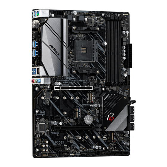
Thank you for purchasing ASRock X570 Phantom Gaming 4 motherboard, a reliable motherboard produced under ASRock’s consistently stringent quality control. It delivers excellent performance with robust design conforming to ASRock’s commitment to quality and endurance.
In this documentation, Chapter 1 and 2 contains the introduction of the motherboard and step-by-step installation guides. Chapter 3 contains the operation guide of the software and utilities. Chapter 4 contains the configuration guide of the BIOS setup.
Because the motherboard specifications and the BIOS software might be updated, the content of this documentation will be subject to change without notice. In case any modifications of this documentation occur, the updated version will be available on ASRock’s website without further notice. If you require technical support related to this motherboard, please visit our website for specific information about the model you are using. You may find the latest VGA cards and CPU support list on ASRock’s website as well. ASRock website http://www.asrock.com.
1.1 Package Contents
•ASRock X570 Phantom Gaming 4 Motherboard (ATX Form Factor)
•ASRock X570 Phantom Gaming 4 Quick Installation Guide
•ASRock X570 Phantom Gaming 4 Support CD
•2 x Serial ATA (SATA) Data Cables (Optional)
•3 x Screws for M.2 Sockets (Optional)
•1 x I/O Panel Shield
English
1

English
1.2 Specifications
|
Platform |
• |
ATX Form Factor |
|
• |
Solid Capacitor design |
|
|
• |
2oz Copper PCB |
|
|
CPU |
• |
Supports AMD AM4 socket RyzenTM 2000 and 3000 series |
|
processors |
||
|
• |
Digi Power design |
|
|
• 10 Power Phase design |
||
|
Chipset |
• |
AMD X570 |
|
Memory |
• |
Dual Channel DDR4 Memory Technology |
•4 x DDR4 DIMM Slots
•AMD Ryzen series CPUs (Matisse) support DDR4 4066+ (OC)/3466(OC)/3200/2933/2667/2400/2133 ECC & nonECC, un-buffered memory*
•AMD Ryzen series CPUs (Pinnacle Ridge) support DDR4 3466+(OC)/3200(OC)/2933/2667/2400/2133 ECC & nonECC, un-buffered memory*
•AMD Ryzen series CPUs (Picasso) support DDR4 3466+ (OC)/3200(OC)/2933/2667/2400/2133 non-ECC, un-buffered memory*
*For Ryzen Series CPUs (Picasso), ECC is only supported with PRO CPUs.
*Please refer to Memory Support List on ASRock’s website for more information. (http://www.asrock.com/)
*Please refer to page 22 for DDR4 UDIMM maximum frequency support.
•Max. capacity of system memory: 64GB
•15μ Gold Contact in DIMM Slots
Expansion AMD Ryzen series CPUs (Matisse)
Slot • 2 x PCI Express 4.0 x16 Slots (PCIE1/PCIE3: single at x16 (PCIE1); dual at x16 (PCIE1) / x4 (PCIE3))*
2

X570 Phantom Gaming 4
AMD Ryzen series CPUs (Pinnacle Ridge)
• 2 x PCI Express 3.0 x16 Slots (PCIE1/PCIE3: single at x16 (PCIE1); dual at x16 (PCIE1) / x4 (PCIE3))*
AMD Ryzen series CPUs (Picasso)
• 2 x PCI Express 3.0 x16 Slots (PCIE1/PCIE3: single at x8 (PCIE1); dual at x8 (PCIE1) / x4 (PCIE3))*
|
* Supports NVMe SSD as boot disks |
|
|
• 2 x PCI Express 4.0 x1 Slots |
|
|
• Supports AMD Quad CrossFireXTM and CrossFireXTM |
|
|
• 1 x M.2 Socket (Key E), supports type 2230 WiFi/BT module |
|
|
• 15μ Gold Contact in VGA PCIe Slot (PCIE1) |
|
|
Graphics |
• Integrated AMD RadeonTM Vega Series Graphics in Ryzen |
|
Series APU* |
|
|
* Actual support may vary by CPU |
|
|
• DirectX 12, Pixel Shader 5.0 |
|
|
• Shared memory default 2GB. Max Shared memory supports |
|
|
up to 16GB. |
|
|
* The Max shared memory 16GB requires 32GB system memory |
|
|
installed. |
|
|
• Dual graphics output: support HDMI and DisplayPort 1.2 |
|
|
ports by independent display controllers |
|
|
• Supports HDMI 1.4 with max. resolution up to 4K x 2K |
|
|
(4096×2160) @ 30Hz |
|
|
• Supports DisplayPort 1.2 with max. resolution up to 4K x 2K |
|
|
(4096×2160) @ 60Hz |
|
|
• Supports Auto Lip Sync, Deep Color (12bpc), xvYCC and |
|
|
HBR (High Bit Rate Audio) with HDMI 1.4 Ports (Compliant |
|
|
HDMI monitor is required) |
|
|
• Supports HDCP 1.4 with HDMI 1.4 and DisplayPort 1.2 |
|
|
Ports |
|
|
• Supports 4K Ultra HD (UHD) playback with HDMI 1.4 and |
|
|
DisplayPort 1.2 Ports |
|
|
• Supports Microsoft PlayReady® |
English
3

English
|
Audio |
• |
7.1 CH HD Audio with Content Protection (Realtek |
|
ALC1200 Audio Codec) |
||
|
• Premium Blu-ray Audio support |
||
|
• |
Supports Surge Protection |
|
|
• |
ELNA Audio Caps |
|
|
• |
PCB Isolate Shielding |
|
|
• Individual PCB Layers for R/L Audio Channel |
||
|
LAN |
• |
Gigabit LAN 10/100/1000 Mb/s |
|
• |
GigaLAN Intel® I211AT |
|
|
• Supports Wake-On-LAN |
||
|
• |
Supports Lightning/ESD Protection |
|
|
• Supports Energy Efficient Ethernet 802.3az |
||
|
• |
Supports PXE |
|
|
Rear Panel |
• |
3 x Antenna Ports (on I/O Panel Shield) |
|
I/O |
• |
1 x PS/2 Mouse/Keyboard Port |
|
• 1 x HDMI Port |
||
|
• 1 x DisplayPort 1.2 |
||
|
• 2 x USB 3.2 Gen2 Type-A Ports (10 Gb/s) (Supports ESD |
||
|
Protection) |
||
|
• 6 x USB 3.2 Gen1 Ports (Supports ESD Protection) |
||
|
• 1 x RJ-45 LAN Port with LED (ACT/LINK LED and SPEED |
||
|
LED) |
||
|
• HD Audio Jacks: Line in / Front Speaker / Microphone |
||
|
Storage |
• |
8 x SATA3 6.0 Gb/s Connectors, support RAID (RAID 0, |
|
RAID 1 and RAID 10), NCQ, AHCI and Hot Plug |
•1 x Hyper M.2 Socket (M2_1), supports M Key type 2230/2242/2260/2280/22110 M.2 PCI Express module up to Gen4x4 (64 Gb/s) (with Matisse) or Gen3x4 (32 Gb/s) (with Pinnacle Ridge and Picasso)*
•1 x Hyper M.2 Socket (M2_3), supports M Key type 2230/2242/2260/2280/22110 M.2 SATA3 6.0 Gb/s module and M.2 PCI Express module up to Gen4x4 (64 Gb/s) (with Matisse) or Gen3x4 (32 Gb/s) (with Pinnacle Ridge and Picasso)*
*Supports NVMe SSD as boot disks
*Supports ASRock U.2 Kit
4
![]()
X570 Phantom Gaming 4
Connector • 1 x COM Port Header
•1 x TPM Header
•1 x SPI TPM Header
•1 x Power LED and Speaker Header
•2 x RGB LED Headers
*Support in total up to 12V/3A, 36W LED Strip
•1 x Addressable LED Header
*Supports in total up to 5V/3A, 15W LED Strip
•1 x CPU Fan Connector (4-pin)
*The CPU Fan Connector supports the CPU fan of maximum 1A (12W) fan power.
•1 x CPU/Water Pump Fan Connector (4-pin) (Smart Fan Speed Control)
*The CPU/Water Pump Fan supports the water cooler fan of maximum 2A (24W) fan power.
•3 x Chassis/Water Pump Fan Connectors (4-pin) (Smart Fan Speed Control)
*The Chassis/Water Pump Fan supports the water cooler fan of maximum 2A (24W) fan power.
*CPU_FAN2/WP, CHA_FAN1/WP, CHA_FAN2/WP and CHA_FAN3/WP can auto detect if 3-pin or 4-pin fan is in use.
•1 x 24 pin ATX Power Connector
•1 x 8 pin 12V Power Connector
•1 x Front Panel Audio Connector
•1 x AMD LED Fan USB Header
•1 x Thunderbolt AIC Connector (5-pin) (Supports ASRock Thunderbolt AIC Card only)
•1 x USB 2.0 Header (Supports 2 USB 2.0 ports) (Supports ESD Protection)
•2 x USB 3.2 Gen1 Headers (Support 4 USB 3.2 Gen1 ports) (Supports ESD Protection)
|
BIOS |
• |
AMI UEFI Legal BIOS with GUI support |
|
Feature |
• |
Supports “Plug and Play” |
|
• ACPI 5.1 compliance wake up events |
||
|
• |
Supports jumperfree |
|
|
• |
SMBIOS 2.3 support |
• CPU, CPU VDDCR_SOC, DRAM, VPPM, PREM VDD_ CLDO, PERM VDDCR_SOC, +1.8V, VDDP, VDDG, CPU Load-Line Calibration, CPU VDDCR_SOC Load-Line Calibration Voltage Multi-adjustment
English
5

|
Hardware |
• Temperature Sensing: CPU, CPU/Water Pump, Chassis, |
|
Monitor |
Chassis/Water Pump Fans |
|
• Fan Tachometer: CPU, CPU/Water Pump, Chassis, Chassis/ |
|
|
Water Pump Fans |
|
|
• Quiet Fan (Auto adjust chassis fan speed by CPU tempera- |
|
|
ture): CPU, CPU/Water Pump, Chassis, Chassis/Water |
|
|
Pump Fans |
|
|
• Fan Multi-Speed Control: CPU, CPU/Water Pump, Chassis, |
|
|
Chassis/Water Pump Fans |
|
|
• Voltage monitoring: +12V, +5V, +3.3V, CPU Vcore, CPU VD- |
|
|
DCR_SOC, DRAM, PREM VDDCR_SOC, +1.8V, VDDP |
|
|
OS |
• Microsoft® Windows® 10 64-bit |
|
Certifica- |
• FCC, CE |
|
tions |
• ErP/EuP ready (ErP/EuP ready power supply is required) |
* For detailed product information, please visit our website: http://www.asrock.com
Please realize that there is a certain risk involved with overclocking, including adjusting the setting in the BIOS, applying Untied Overclocking Technology, or using third-party overclocking tools. Overclocking may affect your system’s stability, or even cause damage to the components and devices of your system. It should be done at your own risk and expense. We are not responsible for possible damage caused by overclocking.
English
6
X570 Phantom Gaming 4
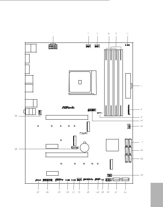
1.3 Motherboard Layout
|
B:USB T:USB USB 2 1 3.2 Gen1 |
/Mouse |
Keyboard PS2 |
1 |
||||||||||||
|
RGB_LED2 |
|||||||||||||||
|
CPU_FAN1 |
CPU_FAN2/WP |
||||||||||||||
|
ATX12V1 |
|||||||||||||||
|
DP1 |
|||||||||||||||
|
HDMI1 |
AM4 SOCKET |
DDR4 A1(64bit,288-pinmodule) |
DDR4 A2(64bit,288-pinmodule) |
DDR4 B1(64bit,288-pinmodule) |
DDR4 B2(64bit,288-pinmodule) |
||||||||||
|
USB 3.2 Gen1 |
|||||||||||||||
|
T: USB3 |
ATXPWR1 |
||||||||||||||
|
B: USB4 |
|||||||||||||||
|
USB 3.2 Gen2 |
|||||||||||||||
|
T: USB1 |
|||||||||||||||
|
B: USB2 |
|||||||||||||||
|
USB 3.2 Gen1 |
Top: |
||||||||||||||
|
T: USB5 |
RJ-45 |
||||||||||||||
|
B: USB6 |
|||||||||||||||
|
SPI_TPM_J1 |
8 |
||||||||||||||
|
CHA_FAN3/WP |
X570 PHANTOM GAMING 4 |
7_ |
|||||||||||||
|
MI Bottom: CI N |
FRONT |
Center: |
LINE Top: IN |
1 |
USB3_ |
||||||||||
|
1 |
|||||||||||||||
|
USB_1 |
|||||||||||||||
|
1 |
|||||||||||||||
|
PCIE1 |
|||||||||||||||
|
M2 1 |
|||||||||||||||
|
CHA_FAN1/WP |
|||||||||||||||
|
2 |
|||||||||||||||
|
RoHS |
M2 |
AMD |
SATA3 5 6 |
||||||||||||
|
PCIE2 |
Premium |
||||||||||||||
|
CMOS |
|||||||||||||||
|
1 |
X570 |
||||||||||||||
|
TB1 |
Battery |
7 8 |
|||||||||||||
|
_ |
|||||||||||||||
|
SATA3 |
|||||||||||||||
|
PCIE3 |
SATA3 1 2 |
||||||||||||||
|
M2 3 |
|||||||||||||||
|
PCIE4 |
SPK_PLED1 |
||||||||||||||
|
1 |
|||||||||||||||
|
COM1 |
CHA_FAN2/WP |
USB3_9_10 |
USB_2_3 |
||||||||||||
|
HD_AUDIO1 |
PLED PWRBTN |
||||||||||||||
|
TPMS1 |
ADDR_LED1 |
CLRCMOS1 |
|||||||||||||
|
1 |
1 |
1 |
1 |
1 |
1 |
||||||||||
|
1 |
1 |
1 |
|||||||||||||
|
RGB_LED1 |
HDLED RESET |
SATA3_3 |
SATA3_4 |
||||||||||||
|
PANEL1 |
English
7

No. Description
1ATX 12V Power Connector (ATX12V1)
2CPU Fan Connector (CPU_FAN1)
3CPU Fan / Waterpump Fan Connector (CPU_FAN2/WP)
42 x 288-pin DDR4 DIMM Slots (DDR4_A1, DDR4_B1)
52 x 288-pin DDR4 DIMM Slots (DDR4_A2, DDR4_B2)
6RGB LED Header (RGB_LED2)
7ATX Power Connector (ATXPWR1)
8USB 3.2 Gen1 Header (USB3_7_8)
9AMD LED Fan USB Header (USB_1)
10SPI TPM Header (SPI_TPM_J1)
11Chassis Fan / Waterpump Fan Connector (CHA_FAN1/WP)
12SATA3 Connector (SATA3_5_6)
13SATA3 Connector (SATA3_7_8)
14SATA3 Connector (SATA3_1_2)
15Power LED and Speaker Header (SPK_PLED1)
16SATA3 Connector (SATA3_4)
17SATA3 Connector (SATA3_3)
18System Panel Header (PANEL1)
19Clear CMOS Jumper (CLRCMOS1)
20USB 2.0 Header (USB_2_3)
21USB 3.2 Gen1 Header (USB3_9_10)
22Chassis Fan / Waterpump Fan Connector (CHA_FAN2/WP)
23Addressable LED Header (ADDR_LED1)
24RGB LED Header (RGB_LED1)
25COM Port Header (COM1)
26TPM Header (TPMS1)
27Front Panel Audio Header (HD_AUDIO1)
28Thunderbolt AIC Header (TB1)
29Chassis Fan / Waterpump Fan Connector (CHA_FAN3/WP)
English
8
X570 Phantom Gaming 4
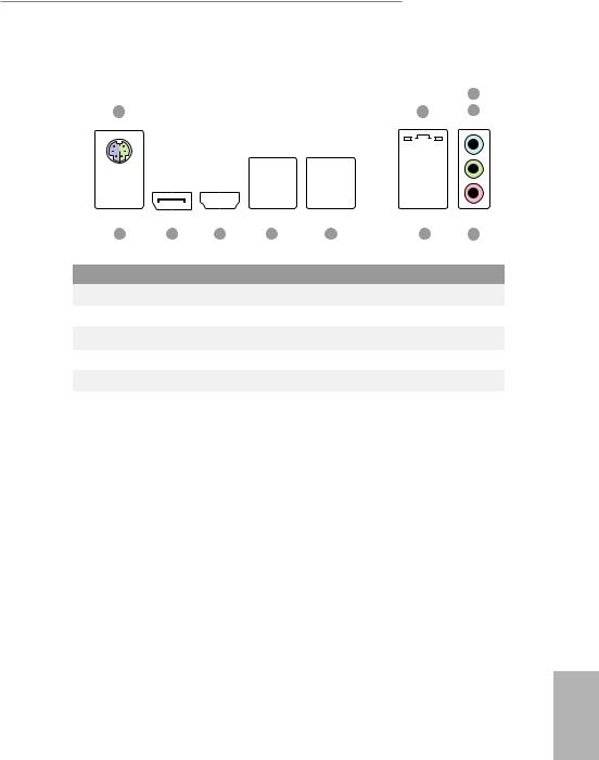
1.4 I/O Panel
|
11 |
10 |
9 |
8 |
7 |
6 |
5 |
|||||||||||||||||||||
|
No. |
Description |
No. |
Description |
||||||||||||||||||||||||
|
1 |
PS/2 Mouse/Keyboard Port |
7 |
USB 3.2 Gen2 Type-A Port (USB31_1_2) |
||||||||||||||||||||||||
|
2 |
LAN RJ-45 Port* |
8 |
USB 3.2 Gen1 Ports (USB3_3_4) |
||||||||||||||||||||||||
|
3 |
Line In (Light Blue) |
9 |
HDMI Port |
||||||||||||||||||||||||
|
4 |
Front Speaker (Lime) |
10 |
DisplayPort 1.2 |
||||||||||||||||||||||||
|
5 |
Microphone (Pink) |
11 |
USB 3.2 Gen1 Ports (USB3_1_2) |
||||||||||||||||||||||||
|
6 |
USB 3.2 Gen1 Ports (USB3_5_6) |
||||||||||||||||||||||||||
English
9

* There are two LEDs on each LAN port. Please refer to the table below for the LAN port LED indications.
ACT/LINK LED
|
SPEED LED |
|||||||||||
|
LAN Port |
|||||||||||
|
Activity / Link LED |
Speed LED |
||||||||||
|
Status |
Description |
Status |
Description |
||||||||
|
Off |
No Link |
Off |
10Mbps connection |
||||||||
|
Blinking |
Data Activity |
Orange |
100Mbps connection |
||||||||
|
On |
Link |
Green |
1Gbps connection |
||||||||
English
10

X570 Phantom Gaming 4
Chapter 2 Installation
This is an ATX form factor motherboard. Before you install the motherboard, study the configuration of your chassis to ensure that the motherboard fits into it.
Pre-installation Precautions
Take note of the following precautions before you install motherboard components or change any motherboard settings.
•Make sure to unplug the power cord before installing or removing the motherboard. Failure to do so may cause physical injuries to you and damages to motherboard components.
•In order to avoid damage from static electricity to the motherboard’s components, NEVER place your motherboard directly on a carpet. Also remember to use a grounded wrist strap or touch a safety grounded object before you handle the components.
•Hold components by the edges and do not touch the ICs.
•Whenever you uninstall any components, place them on a grounded anti-static pad or in the bag that comes with the components.
•When placing screws to secure the motherboard to the chassis, please do not overtighten the screws! Doing so may damage the motherboard.
English
11
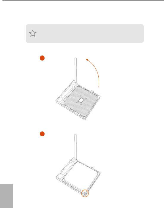
2.1 Installing the CPU
Unplug all power cables before installing the CPU.
1
2
English
12

2.2 Installing the CPU Fan and Heatsink
After you install the CPU into this motherboard, it is necessary to install a larger heatsink and cooling fan to dissipate heat. You also need to spray thermal grease between the CPU and the heatsink to improve heat dissipation. Make sure that the CPU and the heatsink are securely fastened and in good contact with each other.
Please turn off the power or remove the power cord before changing a CPU or heatsink.
Installing the CPU Box Cooler SR1
1
2
English
14

Installing the AM4 Box Cooler SR2
1
2
English
16

X570 Phantom Gaming 4
Installing the AM4 Box Cooler SR3
1
2
English
19

X570 Phantom Gaming 4
5
 4-pin FAN cable
6
|
1 |
||
|
N |
||
|
FA |
||
|
_ |
||
|
PU |
||
|
C |
Please note that this connector is the interface to the LED control board on the SR3, it requires the AMD
|
utility «SR3 Settings Software» to control the LED. |
|
|
*The diagrams shown here are for reference only. The headers might be in a different position on your |
|
|
motherboard. Please refer to page 29 for the orientation of AMD LED Fan USB Header (USB_1). |
21 |
English

English
2.3 Installing Memory Modules (DIMM)
This motherboard provides four 288-pin DDR4 (Double Data Rate 4) DIMM slots, and supports Dual Channel Memory Technology.
1.For dual channel configuration, you always need to install identical (the same brand, speed, size and chip-type) DDR4 DIMM pairs.
2.It is unable to activate Dual Channel Memory Technology with only one or three memory module installed.
3.It is not allowed to install a DDR, DDR2 or DDR3 memory module into a DDR4 slot; otherwise, this motherboard and DIMM may be damaged.
4.We suggest that you install the memory modules on DDR4_A2 and DDR4_B2 first for better DRAM compatibility on 2 DIMMs configuration.
AMD non-XMP Memory Frequency Support
Ryzen Series CPUs (Matisse):
|
UDIMM Memory Slot |
Frequency |
|||
|
A1 |
A2 |
B1 |
B2 |
(Mhz) |
|
— |
SR |
— |
— |
3200 |
|
— |
DR |
— |
— |
3200 |
|
— |
SR |
— |
SR |
3200 |
|
— |
DR |
— |
DR |
3200 |
|
SR |
SR |
SR |
SR |
2933 |
|
SR/DR |
DR |
SR/DR |
DR |
2667 |
|
SR/DR |
SR/DR |
SR/DR |
SR/DR |
2667 |
Ryzen Series CPUs (Pinnacle Ridge):
|
UDIMM Memory Slot |
Frequency |
||||
|
A1 |
A2 |
B1 |
B2 |
(Mhz) |
|
|
— |
SR |
— |
— |
2933 |
|
|
— |
DR |
— |
— |
2933 |
|
|
— |
SR |
— |
SR |
2933 |
|
|
— |
DR |
— |
DR |
2933 |
|
|
SR |
SR |
SR |
SR |
2933 |
|
|
SR/DR |
DR |
SR/DR |
DR |
2667 |
|
|
22 |
SR/DR |
SR/DR |
SR/DR |
SR/DR |
2133-2400 |
Table of Contents for ASROCK X570 PHANTOM GAMING 4:
-
X570 Phantom Gaming 4 129 Polski 1.3 Ustawienia zworek Ta ilustracja pokazuje ustawienia zworek. Po umieszczeniu nasadki zworki na pinach, zworka jest “Zwarta”. Jeśli nasadka zworki nie jest umieszczona na pinach, zworka jest “Otwarta”. Zworka usuwania danych z pamięci CMOS (CLRCMOS1) (sprawdź s.1, Nr 19) Zwarcie: Usunięcie danych z pamięci CMOS Otwarcie: Domyślne CLRCMOS1 umożliwia usunięcie wszystkich danych z pamięci CMOS. Dane w pamięci CMOS obejmują informacje o konguracji systemu, takie jak ha
-
147 X570 Phantom Gaming 4 한 국 어 SPI TPM 헤더 (13 핀 SPI_TPM_J1) (1 페이지 , 10 번 항목 참조 ) 이 커넥터는 키 , 디지털 인 증서 , 암호 및 데이터를 안 전하게 보관할 수 있는 SPI TPM(Trusted Platform Module) 시스템을 지원합니다 . TPM 시 스템은 네트워크 보안을 강화 하고 , 디지털 신원을 보호하며 플랫폼 무결성을 유지합니다 . underbolt AIC 커넥터 (5 핀 TB1) (1
-
171 X570 Phantom Gaming 4 简体中文 CPU 水泵风扇接口 (4 针 CPU_FAN2/WP) (见第 1 页, 第 3 个) 此主板提供 4 针水冷风扇 接口。 如果您打算连接 3 针 CPU 水冷风扇,请将它连接到 针脚 1-3。 ATX 电源接口 (24 针 ATXPWR1) (见第 1 页,第 7 个) 此主板提供 24 针 ATX 电源 接口。 要使用 20 针 ATX 电源,请沿针脚 1 和针脚 13 插接它。 ATX 12V �
-
188 Bahasa Indonesia Konektor • 1 x Header Port COM • 1 x Header TPM • 1 x Header SPI TPM • 1 x Header LED Daya dan Speaker • 2 x Header LED RGB * Mendukung total Strip LED hingga 12V/3A, 36W • 1 x Addressable LED Header * Mendukung total Strip LED hingga 5V/3A, 15W • 1 x Konektor Kipas CPU (4-pin) * Konektor Kipas CPU mendukung kipas CPU dengan daya kipas maksimum 1A (12W). • 1 x Konektor Kipas CPU/Pompa Air (4-pin) (Kontrol Kecepatan Kipas Pintar) * CPU/Kipas Pompa Air mendukung kipas berpen
-
English 14 2.2 Installing the CPU Fan and Heatsink Aer you install the CPU into this motherboard, it is necessary to install a larger heatsink and cooling fan to dissipate heat. You also need to spray thermal grease between the CPU and the heatsink to improve heat dissipation. Make sure that the CPU and the heatsink are securely fastened and in good contact with each other. Installing the CPU Box Cooler SR1 Please turn o the power or remove the power cord before changing a CPU or heatsink.
-
84 Español 1 Introducción Gracias por comprar la placa base ASRock X570 Phantom Gaming 4, una placa base able fabricada según el rigurosísimo control de calidad de ASRock. Ofrece un rendimiento excelente con un diseño resistente de acuerdo con el compromiso de calidad y resistencia de ASRock. 1.1 Contenido del paquete • Placa base ASRock X570 Phantom Gaming 4 (Factor de forma ATX) • Guía de instalación rápida de ASRock X570 Phan
-
51 X570 Phantom Gaming 4 Deutsch 1.3 Jumpereinstellung Die Abbildung zeigt, wie die Jumper eingestellt werden. Wenn die Jumper-Kappe auf den Kontakten angebracht ist, ist der Jumper „kurzgeschlossen“. Wenn keine Jumper-Kappe auf den Kontakten angebracht ist, ist der Jumper „oen“. CMOS-löschen-Jumper (CLRCMOS1) (siehe S. 1, Nr. 19) Kurzgeschlossen: CMOS löschen Oen: Standard CLRCMOS1 ermöglicht Ihnen die Löschung der Daten im CMOS. Die Daten im CMOS beinhaltet Systemeinrichtungsinformationen, wie Systemkennwort, Datum
-
92 Español Conectores Serie ATA3 (SATA3_5_6: consulte la pág.1, nº 12) (SATA3_7_8: consulte la pág. 1, nº 13) (SATA3_1_2: consulte la pág. 1, nº 14) (SATA3_3: consulte la pág. 1, nº 17) (SATA3_4: consulte la pág. 1, nº 16) Estos ocho conectores SATA3 son compatibles con cables de datos SATA para dispositivos de almacenamiento interno con una velocidad de transferencia de datos de hasta 6,0 Gb/s. Base de conexiones USB de ventilador de LED AMD (USB_
-
157 X570 Phantom Gaming 4 日本語 シリアル ATA3 コネクタ (SATA3_5_6: p.1、No. 12 参照) (SATA3_7_8: p.1、No. 13 を参照) (SATA3_1_2: p.1、No. 14 参照) (SATA3_3: p.1、No. 17 参照) (SATA3_4: p.1、No. 16 参照) これら 8 つの SATA3 コネクタは最高 6.0Gb/s のデーター転送速度を サポートし、内部ストレー ジデバイス用の SATA データーケーブルに対 応致します。
-
English 38 A A 20 o Step 3 Gently insert the WiFi/BT module into the M.2 slot. Please be aware that the module only ts in one orientation. A Step 4 Tighten the screw with a screwdriver to secure the module into place. Please do not overtighten the screw as this might damage the module.
-
136 한 국 어 1 개요 ASRock X570 Phantom Gaming 4 마더보드를 구입해 주셔서 감사합니다 . 이 마더보드 는 ASRock 의 일관되고 엄격한 품질관리 하에 생산되어 신뢰성이 우수합니다 . 품질과 내구성에 대한 ASRock 의 기준에 부합하는 우수한 성능과 견고한 설계를 제공합니다 . 1.1 포장 내용물 • ASRock X570 Phantom Gaming 4 마더보드 (ATX 폼 팩터 ) • ASRock X570 Phantom Gaming 4 간편 설치 안내서 • ASRock X570 Phantom Gaming 4 지원 CD • 시리얼
-
62 Français Connecteur • 1 x embase pour port COM • 1 x embase TPM • 1 x embase SPI TPM • 1 x prise DEL d’alimentation et haut-parleur • 2 x embase LED RVB * Prend en charge les rubans LED jusqu’à 12 V/3 A, 36 W au total • 1 x embase LED adressable * Prend en charge les rubans LED jusqu’à 5 V/3 A, 15 W au total • 1 x connecteur pour ventilateur de CPU (4 broches) * Le connecteur pour ventilateur de CPU prend en charge un ventilateur de CPU d’une puissance maximale de 1 A (12 W). • 1 x conn
-
English 19 X570 Phantom Gaming 4 Installing the AM4 Box Cooler SR3 1 2
Questions, Opinions and Exploitation Impressions:
You can ask a question, express your opinion or share our experience of ASROCK X570 PHANTOM GAMING 4 device using right now.
|
Detail Specifications: 1887/1887622-x570_phantom_gaming_4.pdf file (04 Oct 2022) |
Accompanying Data:
ASROCK X570 PHANTOM GAMING 4 Motherboard PDF Manual (Updated: Tuesday 4th of October 2022 04:14:34 AM)
Rating: 4.5 (rated by 47 users)
Compatible devices: B550D4-4L, FM2A88M Pro3 Plus, A780GMH 128M, K7S41GX, B85M-ITX, AD2550RA/U3S3, H77M-ITX, FM2A85M-DG3.
Recommended Documentation:
Text Version of Manual
(Ocr-Read Summary of Contents, UPD: 04 October 2022)
-
188, ASROCK X570 PHANTOM GAMING 4 186 Bahasa Indonesia CPU Seri AMD Ryzen (Pinnacle Ridge) • 2 x PCI Express 3.0 x16 Slot (PCIE1/PCIE3:satu pada x16 (PCIE1); dua pada x16 (PCIE1) / x4 (PCIE3))* CPU seri AMD Ryzen (Picasso) • 2 x PCI Express 3.0 x16 Slot (PCIE1/PCIE3:satu pada x8 (PCIE1); dua pada x8 (PCIE1) / x4 (PCIE3))* * Mendukung SSD NVMe sebagai disk boot • 2 x Slot PCI Express 4.0 x1 • Mendukung AMD Q…
-
50, 48 Deutsch Audio • 7.1-Kanal-HD-Audio mit Inhaltsschutz (Realtek ALC1200- Audiocodec) • Erstklassige Blu-ray-Audiounterstützung • Unterstützt Überspannungsschutz • ELNA-Audiokondensatoren • PCB-isolierte Abschirmung • Individuelle PCB-Layer für rechten/linken Audiokanal LAN • Gigabit LAN 10/100/1000 Mb/s • GigaLAN Intel® I211AT • Unters…
-
99, X570 Phantom Gaming 4 Русский 97 1 Введение Благодарим вас за приобретение надежной материнской платы ASRock X570 Phantom Gaming 4, выпускаемой под постоянным строгим контролем компании ASRock. Эта материнская плата обеспечивае�…
-
105, X570 Phantom Gaming 4 Русский 103 1.3 Установка перемычек Установка перемычек показана на рисунке. При установке перемычки-колпачка на контакты перемычка «замкнута». Если перемычка-колпачок на контакты не установлена, пер…
-
70, 68 Français Connecteur pour ventilateur de pompe à eau du processeur (CPU_FAN2/WP à 4 broches) (voir p.1, No. 3) Cette carte mère est dotée d’un connecteur pour ventilateur de processeur à refroidissement par eau à 4 broches. Si vous envisagez de connecter un ventilateur de refroidisseur d’eau pour processeur à 3 broches, veuillez le brancher sur…
-
184, ASROCK X570 PHANTOM GAMING 4 182 繁體中文 前面板音訊排針 (9-pin HD_AUDIO1) (請參閱第 1 頁,編號 27) 本排針適用於連接音訊 裝置至前面板音訊。 機殼/水冷幫浦風扇 接頭 (4-pin CHA_FAN1/WP) (請參閱第 1 頁, 編號 11) (4-pin CHA_FAN2/WP) (請參閱第 1 頁, 編號 22) (4-pin CHA_FAN3/WP) (請參閱第 1 頁, 編號 29) 本主機…
-
110, Русский 108 Колодка ТРМ (17-контактов, TPMS1) (см. стр. 1, № 26) Этот разъем обеспечивает поддержку системы Trusted Platform Module (TPM), которая способна обеспечить надежное хранение ключей, цифровых сертификатов, пароле�…
-
139, ASROCK X570 PHANTOM GAMING 4 137 X570 Phantom Gaming 4 한 국 어 1.2 규격 플랫폼 • ATX 폼 팩터 • 솔리드 콘덴서 구조 • 2 온스 구리 PCB CPU • AMD AM4 소켓 Ryzen TM 2000 및 3000 시리즈 프로세서 지원 • Digi Power design • 10 개 전원 위상 구조 칩세트 • AMD X570 메모리 • 듀얼 채널 DDR4 메모리 기술 • DDR4 DIMM 슬롯 4 개…
-
90, 88 Español Conector • 1 x Base de conexiones de puerto COM • 1 x Conector TPM • 1 x Conector SPI TPM • 1 x LED de alimentación y base de conexiones para el altavoz • 2 x Cabezales de indicador LED RGB * Admite una tira de LED de hasta 12 V/3 A (36 W) en total • 1 x Base de conexiones de LED direccionable * Admite una tira de LED de hasta 5 V/…
-
84, 82 Italiano Connettore SPI TPM (SPI_TPM_J1 a 13 pin) (vedere pag. 1, n. 10) Questo connettore supporta il sistema SPI Trusted Platform Module (TPM), che può archiviare in modo sicuro chiavi, certicati digitali, password e dati. Un sistema TPM permette anche di potenziare la sicurezza della rete, di proteggere identità digitali e di garantire l’integrità della piattaform…
Recommended Instructions:
8799, TFTV680S, HX1901QV, Christie LW25U, Oce Printing System


-
1AMD RAID Installation Guide 1. AMD BIOS RAID Installation Guide …………………………………………………………………….. 2 1.1 Introduction to RAID ……………………………………………………………………………….. 2 1.2 RAID Configurations Precautions ……………………………………………… …
M3A785GMH/128M 17
-
www.infineon.comPlease note that Cypress is an Infineon Technologies Company.The document following this cover page is marked as “Cypress” document as this is the company that originally developed the product. Please note that Infineon will continue to oer the product to new and existing customers as part of the Infineon product portfolio.Continuity of document contentThe fact that I …
Cypress CYTVII-B-H-8M-176-CPU 79
-
Intel® Desktop Board DP67BA Technical Product Specification June 2012 Order Number: G14709-004 The Intel Desktop Board DP67BA may contain design defects or errors known as errata that may cause the product to deviate from published specifications. Current characterized errata are documented in the Intel Desktop Board DP67BA Specification Update. …
DP67BA 90
-
SMART ARM-based Microcontrollers SAM R21 Xplained Pro USER GUIDEPrefaceThe Atmel® SAM R21 Xplained Pro evaluation kit is a hardware platform toevaluate the ATSAMR21G18A microcontroller.Supported by the Atmel Studio integrated development platform, the kitprovides easy access to the features of the Atmel ATSAMR21G18A andexplains how to integrate the device in a cust …
SAM R21 Xplained Pro 31
Popular Right Now:
Operating Impressions, Questions and Answers:
Посмотреть инструкция для Asrock X570 Phantom Gaming 4 WiFi ax бесплатно. Руководство относится к категории материнские платы, 1 человек(а) дали ему среднюю оценку 7.5. Руководство доступно на следующих языках: английский. У вас есть вопрос о Asrock X570 Phantom Gaming 4 WiFi ax или вам нужна помощь? Задайте свой вопрос здесь
Главная
Не можете найти ответ на свой вопрос в руководстве? Вы можете найти ответ на свой вопрос ниже, в разделе часто задаваемых вопросов о Asrock X570 Phantom Gaming 4 WiFi ax.
Инструкция Asrock X570 Phantom Gaming 4 WiFi ax доступно в русский?
Не нашли свой вопрос? Задайте свой вопрос здесь
View a manual of the Asrock X570 Phantom Gaming 4 WiFi ax below. All manuals on ManualsCat.com can be viewed completely free of charge. By using the ‘Select a language’ button, you can choose the language of the manual you want to view.
Page: 1
Version 1.0
Published June 2019
Copyright©2019 ASRock INC. All rights reserved.
Copyright Notice:
No part of this documentation may be reproduced, transcribed, transmitted, or
translated in any language, in any form or by any means, except duplication of
documentation by the purchaser for backup purpose, without written consent of
ASRock Inc.
Products and corporate names appearing in this documentation may or may not
be registered trademarks or copyrights of their respective companies, and are used
only for identification or explanation and to the owners’ benefit, without intent to
infringe.
Disclaimer:
Specifications and information contained in this documentation are furnished for
informational use only and subject to change without notice, and should not be
constructed as a commitment by ASRock. ASRock assumes no responsibility for
any errors or omissions that may appear in this documentation.
With respect to the contents of this documentation, ASRock does not provide
warranty of any kind, either expressed or implied, including but not limited to
the implied warranties or conditions of merchantability or fitness for a particular
purpose.
In no event shall ASRock, its directors, officers, employees, or agents be liable for
any indirect, special, incidental, or consequential damages (including damages for
loss of profits, loss of business, loss of data, interruption of business and the like),
even if ASRock has been advised of the possibility of such damages arising from any
defect or error in the documentation or product.
This device complies with Part 15 of the FCC Rules. Operation is subject to the following
two conditions:
(1) this device may not cause harmful interference, and
(2) this device must accept any interference received, including interference that
may cause undesired operation.
CALIFORNIA, USA ONLY
The Lithium battery adopted on this motherboard contains Perchlorate, a toxic substance
controlled in Perchlorate Best Management Practices (BMP) regulations passed by the
California Legislature. When you discard the Lithium battery in California, USA, please
follow the related regulations in advance.
“Perchlorate Material-special handling may apply, see www.dtsc.ca.gov/hazardouswaste/
perchlorate”
ASRock Website: http://www.asrock.com
Page: 2
AUSTRALIA ONLY
Our goods come with guarantees that cannot be excluded under the Australian Consumer
Law. You are entitled to a replacement or refund for a major failure and compensation for
any other reasonably foreseeable loss or damage caused by our goods. You are also entitled
to have the goods repaired or replaced if the goods fail to be of acceptable quality and the
failure does not amount to a major failure. If you require assistance please call ASRock Tel
: +886-2-28965588 ext.123 (Standard International call charges apply)
The terms HDMI® and HDMI High-Definition Multimedia Interface, and the
HDMI logo are trademarks or registered trademarks of HDMI Licensing LLC in the
United States and other countries.
Page: 3
CE Warning
This device complies with directive 2014/53/EU issued by the Commision of the European
Community.
This equipment complies with EU radiation exposure limits set forth for an uncontrolled
environment.
This equipment should be installed and operated with minimum distance 20cm between
the radiator & your body.
Operations in the 5.15-5.35GHz band are restricted to indoor usage only.
Radio transmit power per transceiver type
Function Frequency Maximum Output Power (EIRP)
WiFi
2400-2483.5 MHz 18.5 + / -1.5 dbm
5150-5250 MHz 21.5 + / -1.5 dbm
5250-5350 MHz
18.5 + / -1.5 dbm (no TPC)
21.5 + / -1.5 dbm (TPC)
5470-5725 MHz
25.5 + / -1.5 dbm (no TPC)
28.5 + / -1.5 dbm (TPC)
Bluetooth 2400-2483.5 MHz 8.5 + / -1.5 dbm
Page: 4
Contents
Chapter 1 Introduction 1
1.1 Package Contents 1
1.2 Specifications 2
1.3 Motherboard Layout 7
1.4 I/O Panel 9
1.5 WiFi-802.11ax Module and ASRock WiFi 2.4/5 GHz Antenna 10
Chapter 2 Installation 13
2.1 Installing the CPU 14
2.2 Installing the CPU Fan and Heatsink 16
2.3 Installing Memory Modules (DIMM) 24
2.4 Expansion Slots (PCI Express Slots) 27
2.5 Jumpers Setup 28
2.6 Onboard Headers and Connectors 29
2.7 Post Status Checker 35
2.8 CrossFireXTM
and Quad CrossFireXTM
Operation Guide 36
2.8.1 Installing Two CrossFireXTM
-Ready Graphics Cards 36
2.8.2 Driver Installation and Setup 38
2.9 M.2_SSD (NGFF) Module Installation Guide (M2_1) 39
2.10 M.2_SSD (NGFF) Module Installation Guide (M2_3) 42
Chapter 3 Software and Utilities Operation 45
3.1 Installing Drivers 45
3.2 Phantom Gaming Tuning 46
Page: 5
3.3 ASRock Live Update & APP Shop 49
3.3.1 UI Overview 49
3.3.2 Apps 50
3.3.3 BIOS & Drivers 53
3.3.4 Setting 54
3.4 ASRock Polychrome SYNC 55
Chapter 4 UEFI SETUP UTILITY 58
4.1 Introduction 58
4.1.1 UEFI Menu Bar 58
4.1.2 Navigation Keys 59
4.2 Main Screen 60
4.3 OC Tweaker Screen 61
4.4 Advanced Screen 65
4.4.1 CPU Configuration 66
4.4.2 Onboard Devices Configuration 67
4.4.3 Storage Configuration 69
4.4.4 ACPI Configuration 70
4.4.5 Super IO Configuration 71
4.4.6 Trusted Computing 72
4.4.7 AMD CBS 73
4.4.8 AMD PBS 74
4.4.9 AMD Overclocking 75
4.5 Tools 76
4.6 Hardware Health Event Monitoring Screen 77
Page: 6
4.7 Security Screen 80
4.8 Boot Screen 81
4.9 Exit Screen 83
Page: 7
English
1
X570 Phantom Gaming 4 WiFi ax
Chapter 1 Introduction
Thank you for purchasing ASRock X570 Phantom Gaming 4 WiFi ax motherboard,
a reliable motherboard produced under ASRock’s consistently stringent quality
control. It delivers excellent performance with robust design conforming to
ASRock’s commitment to quality and endurance.
In this documentation, Chapter 1 and 2 contains the introduction of the
motherboard and step-by-step installation guides. Chapter 3 contains the operation
guide of the software and utilities. Chapter 4 contains the configuration guide of
the BIOS setup.
1.1 Package Contents
• ASRock X570 Phantom Gaming 4 WiFi ax Motherboard (ATX Form Factor)
• ASRock X570 Phantom Gaming 4 WiFi ax Quick Installation Guide
• ASRock X570 Phantom Gaming 4 WiFi ax Support CD
• 2 x Serial ATA (SATA) Data Cables (Optional)
• 2 x SMA WiFi Antenna Cables
• 1 x ASRock WiFi 2.4/5 GHz Antenna
• 2 x Screws for M.2 Sockets (Optional)
• 1 x I/O Panel Shield
Because the motherboard specifications and the BIOS software might be updated, the
content of this documentation will be subject to change without notice. In case any
modifications of this documentation occur, the updated version will be available on
ASRock’s website without further notice. If you require technical support related to
this motherboard, please visit our website for specific information about the model
you are using. You may find the latest VGA cards and CPU support list on ASRock’s
website as well. ASRock website http://www.asrock.com.
Page: 8
English
2
1.2 Specifications
Platform • ATX Form Factor
• Solid Capacitor design
• 2oz Copper PCB
CPU • Supports AMD AM4 socket RyzenTM
2000 and 3000 series
processors
• Digi Power design
• 10 Power Phase design
Chipset • AMD X570
Memory • Dual Channel DDR4 Memory Technology
• 4 x DDR4 DIMM Slots
• AMD Ryzen series CPUs (Matisse) support DDR4 4066+
(OC)/3466(OC)/3200/2933/2667/2400/2133 ECC & non-
ECC, un-buffered memory*
• AMD Ryzen series CPUs (Pinnacle Ridge) support DDR4
3466+(OC)/3200(OC)/2933/2667/2400/2133 ECC & non-
ECC, un-buffered memory*
• AMD Ryzen series CPUs (Picasso) support DDR4 3466+
(OC)/3200(OC)/2933/2667/2400/2133 non-ECC, un-buffered
memory*
* For Ryzen Series CPUs (Picasso), ECC is only supported with
PRO CPUs.
* Please refer to Memory Support List on ASRock’s website for
more information. (http://www.asrock.com/)
* Please refer to page 24 for DDR4 UDIMM maximum
frequency support.
• Max. capacity of system memory: 128GB
• 15μ Gold Contact in DIMM Slots
Expansion
Slot
AMD Ryzen series CPUs (Matisse)
• 2 x PCI Express 4.0 x16 Slots (PCIE1/PCIE3: single at x16
(PCIE1); dual at x16 (PCIE1) / x4 (PCIE3))*
Page: 9
English
3
X570 Phantom Gaming 4 WiFi ax
AMD Ryzen series CPUs (Pinnacle Ridge)
• 2 x PCI Express 3.0 x16 Slots (PCIE1/PCIE3: single at x16
(PCIE1); dual at x16 (PCIE1) / x4 (PCIE3))*
AMD Ryzen series CPUs (Picasso)
• 2 x PCI Express 3.0 x16 Slots (PCIE1/PCIE3: single at x8
(PCIE1); dual at x8 (PCIE1) / x4 (PCIE3))*
* Supports NVMe SSD as boot disks
• 2 x PCI Express 4.0 x1 Slots
• Supports AMD Quad CrossFireXTM
and CrossFireXTM
• 1 x M.2 Socket (Key E) with the bundled WiFi-802.11ax
module
• 15μ Gold Contact in VGA PCIe Slot (PCIE1)
Graphics • Integrated AMD RadeonTM
Vega Series Graphics in Ryzen
Series APU*
* Actual support may vary by CPU
• DirectX 12, Pixel Shader 5.0
• Shared memory default 2GB. Max Shared memory supports
up to 16GB.
* The Max shared memory 16GB requires 32GB system memory
installed.
• Dual graphics output: support HDMI and DisplayPort 1.2
ports by independent display controllers
• Supports HDMI 2.0 with max. resolution up to 4K x 2K
(4096×2160) @ 30Hz
• Supports DisplayPort 1.2 with max. resolution up to 4K x 2K
(4096×2160) @ 60Hz
• Supports Auto Lip Sync, Deep Color (12bpc), xvYCC and
HBR (High Bit Rate Audio) with HDMI 2.0 Ports (Compliant
HDMI monitor is required)
• Supports HDCP 2.2 with HDMI 2.0 and DisplayPort 1.2
Ports
• Supports 4K Ultra HD (UHD) playback with HDMI 2.0 and
DisplayPort 1.2 Ports
• Supports Microsoft PlayReady®
Page: 10
English
4
Audio • 7.1 CH HD Audio with Content Protection (Realtek
ALC1200 Audio Codec)
• Premium Blu-ray Audio support
• Supports Surge Protection
• ELNA Audio Caps
• PCB Isolate Shielding
• Individual PCB Layers for R/L Audio Channel
LAN • Gigabit LAN 10/100/1000 Mb/s
• GigaLAN Intel® I211AT
• Supports Wake-On-LAN
• Supports Lightning/ESD Protection
• Supports Energy Efficient Ethernet 802.3az
• Supports PXE
Wireless
LAN
• Intel® 802.11ax WiFi Module
• Supports IEEE 802.11a/b/g/n/ax
• Supports Dual-Band (2.4/5 GHz)
• Supports high speed wireless connections up to 2.4Gbps
• 2 antennas to support 2 (Transmit) x 2 (Receive) diversity
technology
• Supports Bluetooth 5.2 + High speed class II
• Supports MU-MIMO
Rear Panel
I/O
• 3 x Antenna Ports (on I/O Panel Shield)
• 1 x PS/2 Mouse/Keyboard Port
• 1 x HDMI Port
• 1 x DisplayPort 1.2
• 2 x USB 3.2 Gen2 Type-A Ports (10 Gb/s) (Supports ESD
Protection)
• 6 x USB 3.2 Gen1 Ports (Supports ESD Protection)
• 1 x RJ-45 LAN Port with LED (ACT/LINK LED and SPEED
LED)
• HD Audio Jacks: Line in / Front Speaker / Microphone
Page: 11
English
5
X570 Phantom Gaming 4 WiFi ax
Storage • 8 x SATA3 6.0 Gb/s Connectors, support RAID (RAID 0,
RAID 1 and RAID 10), NCQ, AHCI and Hot Plug
• 1 x Hyper M.2 Socket (M2_1), supports M Key type
2230/2242/2260/2280/22110 M.2 PCI Express module up to
Gen4x4 (64 Gb/s) (with Matisse) or Gen3x4 (32 Gb/s) (with
Pinnacle Ridge and Picasso)*
• 1 x Hyper M.2 Socket (M2_3), supports M Key type
2230/2242/2260/2280/22110 M.2 SATA3 6.0 Gb/s module
and M.2 PCI Express module up to Gen4x4 (64 Gb/s) (with
Matisse) or Gen3x4 (32 Gb/s) (with Pinnacle Ridge and
Picasso)*
* Supports NVMe SSD as boot disks
* Supports ASRock U.2 Kit
Connector • 1 x COM Port Header
• 1 x TPM Header
• 1 x SPI TPM Header
• 1 x Power LED and Speaker Header
• 2 x RGB LED Headers
* Support in total up to 12V/3A, 36W LED Strip
• 1 x Addressable LED Header
* Supports in total up to 5V/3A, 15W LED Strip
• 1 x CPU Fan Connector (4-pin)
* The CPU Fan Connector supports the CPU fan of maximum
1A (12W) fan power.
• 1 x CPU/Water Pump Fan Connector (4-pin) (Smart Fan
Speed Control)
* The CPU/Water Pump Fan supports the water cooler fan of
maximum 2A (24W) fan power.
• 3 x Chassis/Water Pump Fan Connectors (4-pin) (Smart Fan
Speed Control)
* The Chassis/Water Pump Fan supports the water cooler fan of
maximum 2A (24W) fan power.
* CPU_FAN2/WP, CHA_FAN1/WP, CHA_FAN2/WP and
CHA_FAN3/WP can auto detect if 3-pin or 4-pin fan is in use.
• 1 x 24 pin ATX Power Connector
• 1 x 8 pin 12V Power Connector
• 1 x Front Panel Audio Connector
• 1 x AMD LED Fan USB Header
• 1 x Thunderbolt AIC Connector (5-pin) (Supports ASRock
Thunderbolt AIC Card only)
Page: 12
English
6
• 1 x USB 2.0 Header (Supports 2 USB 2.0 ports) (Supports
ESD Protection)
• 2 x USB 3.2 Gen1 Headers (Support 4 USB 3.2 Gen1 ports)
(Supports ESD Protection)
BIOS
Feature
• AMI UEFI Legal BIOS with GUI support
• Supports “Plug and Play”
• ACPI 5.1 compliance wake up events
• Supports jumperfree
• SMBIOS 2.3 support
• CPU, CPU VDDCR_SOC, DRAM, VPPM, PREM VDD_
CLDO, PERM VDDCR_SOC, +1.8V, VDDP, VDDG, CPU
Load-Line Calibration, CPU VDDCR_SOC Load-Line
Calibration Voltage Multi-adjustment
Hardware
Monitor
• Temperature Sensing: CPU, CPU/Water Pump, Chassis,
Chassis/Water Pump Fans
• Fan Tachometer: CPU, CPU/Water Pump, Chassis, Chassis/
Water Pump Fans
• Quiet Fan (Auto adjust chassis fan speed by CPU tempera-
ture): CPU, CPU/Water Pump, Chassis, Chassis/Water
Pump Fans
• Fan Multi-Speed Control: CPU, CPU/Water Pump, Chassis,
Chassis/Water Pump Fans
• Voltage monitoring: +12V, +5V, +3.3V, CPU Vcore, CPU VD-
DCR_SOC, DRAM, PREM VDDCR_SOC, +1.8V, VDDP
OS • Microsoft® Windows® 10 64-bit
Certifica-
tions
• FCC, CE
• ErP/EuP ready (ErP/EuP ready power supply is required)
Please realize that there is a certain risk involved with overclocking, including
adjusting the setting in the BIOS, applying Untied Overclocking Technology, or using
third-party overclocking tools. Overclocking may affect your system’s stability, or
even cause damage to the components and devices of your system. It should be done
at your own risk and expense. We are not responsible for possible damage caused by
overclocking.
* For detailed product information, please visit our website: http://www.asrock.com
Page: 13
English
7
X570 Phantom Gaming 4 WiFi ax
1.3 Motherboard Layout
DDR4_A2
(64
bit,
288-pin
module)
DDR4_A1
(64
bit,
288-pin
module)
DDR4_B2
(64
bit,
288-pin
module)
DDR4_B1
(64
bit,
288-pin
module)
ATXPWR1
PCIE1
USB 3.2 Gen1
T: USB3
B: USB4
USB 3.2 Gen1
T: USB5
B: USB6
Top:
LINE
IN
Center:
FRONT
Bottom:
MIC
IN
HDLED RESET
PLED PWRBTN
PANEL1
1
1
SPK_PLED1
1
HD_AUDIO1
SATA3_5_6
SATA3_7_8
SATA3_4
8
10
14
12
13
15
16
SATA3_1_2
17
18
19
24
USB_2_3
1
25
1
7
6
20
USB
3.2
Gen1
T:
USB1
B:
USB2
PS2
Keyboard
/Mouse
26
CPU_FAN1
9
1
TPMS1
M2_1
CHA_FAN3/WP
CPU_FAN2/WP
5
4
USB3_7_8
1
22 21
RoHS
PCIE4
Top:
RJ-45
AMD
Premium
X570
SOCKET
AM4
CHA_FAN2/WP
28
29
27
ADDR_LED1
1
3
PCIE2
DP1
2
11
TB1
1
X570 Phantom Gaming 4 WiFi ax
RGB_LED2
1
1
USB_1
ATX12V1
PCIE3
CMOS
Battery
CHA_FAN1/WP
CLRCMOS1
1
23
HDMI1
USB 3.2 Gen2
T: USB1
B: USB2
SPI_TPM_J1
1
SATA3_3
M2_3
M2_2
COM1
1
RGB_LED1
1
USB3_9_10
1
WiFi-802.11ax
Module
Page: 14
English
8
No. Description
1 ATX 12V Power Connector (ATX12V1)
2 CPU Fan Connector (CPU_FAN1)
3 CPU Fan / Waterpump Fan Connector (CPU_FAN2/WP)
4 2 x 288-pin DDR4 DIMM Slots (DDR4_A1, DDR4_B1)
5 2 x 288-pin DDR4 DIMM Slots (DDR4_A2, DDR4_B2)
6 RGB LED Header (RGB_LED2)
7 ATX Power Connector (ATXPWR1)
8 USB 3.2 Gen1 Header (USB3_7_8)
9 AMD LED Fan USB Header (USB_1)
10 SPI TPM Header (SPI_TPM_J1)
11 Chassis Fan / Waterpump Fan Connector (CHA_FAN1/WP)
12 SATA3 Connector (SATA3_5_6)
13 SATA3 Connector (SATA3_7_8)
14 SATA3 Connector (SATA3_1_2)
15 Power LED and Speaker Header (SPK_PLED1)
16 SATA3 Connector (SATA3_4)
17 SATA3 Connector (SATA3_3)
18 System Panel Header (PANEL1)
19 Clear CMOS Jumper (CLRCMOS1)
20 USB 2.0 Header (USB_2_3)
21 USB 3.2 Gen1 Header (USB3_9_10)
22 Chassis Fan / Waterpump Fan Connector (CHA_FAN2/WP)
23 Addressable LED Header (ADDR_LED1)
24 RGB LED Header (RGB_LED1)
25 COM Port Header (COM1)
26 TPM Header (TPMS1)
27 Front Panel Audio Header (HD_AUDIO1)
28 Thunderbolt AIC Header (TB1)
29 Chassis Fan / Waterpump Fan Connector (CHA_FAN3/WP)
Page: 15
English
9
X570 Phantom Gaming 4 WiFi ax
1.4 I/O Panel
No. Description No. Description
1 PS/2 Mouse/Keyboard Port 7 USB 3.2 Gen2 Type-A Port (USB31_1_2)
2 LAN RJ-45 Port* 8 USB 3.2 Gen1 Ports (USB3_3_4)
3 Line In (Light Blue)** 9 HDMI Port
4 Front Speaker (Lime)** 10 DisplayPort 1.2
5 Microphone (Pink)** 11 USB 3.2 Gen1 Ports (USB3_1_2)
6 USB 3.2 Gen1 Ports (USB3_5_6)
1
6
7
10
2
11 9 5
4
3
8
* There are two LEDs on each LAN port. Please refer to the table below for the LAN port LED indications.
Activity / Link LED Speed LED
Status Description Status Description
Off No Link Off 10Mbps connection
Blinking Data Activity Orange 100Mbps connection
On Link Green 1Gbps connection
ACT/LINK LED
SPEED LED
LAN Port
** Function of the Audio Ports in 7.1-channel Configuration:
Port Function
Light Blue (Rear panel) Rear Speaker Out
Lime (Rear panel) Front Speaker Out
Pink (Rear panel) Central /Subwoofer Speaker Out
Lime (Front panel) Side Speaker Out
Page: 16
English
10
1.5 WiFi-802.11ax Module and ASRock WiFi 2.4/5 GHz Antenna
WiFi-802.11ax + BT Module
This motherboard comes with an exclusive WiFi 802.11 a/b/g/n/ax + BT v5.2 module
that offers support for WiFi 802.11 a/b/g/n/ax connectivity standards and Bluetooth
v5.2. WiFi + BT module is an easy-to-use wireless local area network (WLAN) adapter
to support WiFi + BT. Bluetooth v5.2 standard features Smart Ready technology that
adds a whole new class of functionality into the mobile devices. BT 5.2 also includes
Low Energy Technology and ensures extraordinary low power consumption for PCs.
The 2T2R WiFi solution sets a WiFi high speed standard and offers max link rate up
to 2.4Gbps.
* The transmission speed may vary according to the environment.
ASRock WiFi 2.4/5 GHz Antenna
Page: 17
English
11
X570 Phantom Gaming 4 WiFi ax
WiFi Module and WiFi Antenna Installation Guide
Step 1
Prepare the SMA Wi-Fi Antenna Cables
and WiFi 2.4/5 GHz Antenna that comes
with the package.
Step 2
Attach the SMA Wi-Fi Antenna Cables to
the WiFi Module.
Step 3
Insert the RP-SMA Wi-Fi Antenna Con-
nectors to the antenna ports on the I/O
shield.
Step 4
Fasten the screw nuts to secure the
antenna connectors.
Page: 18
English
12
Step 5
Connect the WiFi 2.4/5 GHz
Antenna to the antenna connectors. Turn
the antenna clockwise until it is securely
connected.
Step 6
Set the WiFi 2.4/5 GHz Antenna at 90-de-
gree angle.
*You may need to adjust the direction of
the antenna for a stronger signal.
Page: 19
English
13
X570 Phantom Gaming 4 WiFi ax
This is an ATX form factor motherboard. Before you install the motherboard, study
the configuration of your chassis to ensure that the motherboard fits into it.
Pre-installation Precautions
Take note of the following precautions before you install motherboard components
or change any motherboard settings.
• Make sure to unplug the power cord before installing or removing the motherboard.
Failure to do so may cause physical injuries to you and damages to motherboard
components.
• In order to avoid damage from static electricity to the motherboard’s components,
NEVER place your motherboard directly on a carpet. Also remember to use a grounded
wrist strap or touch a safety grounded object before you handle the components.
• Hold components by the edges and do not touch the ICs.
• Whenever you uninstall any components, place them on a grounded anti-static pad or
in the bag that comes with the components.
• When placing screws to secure the motherboard to the chassis, please do not over-
tighten the screws! Doing so may damage the motherboard.
Chapter 2 Installation
Page: 20
English
14
2.1 Installing the CPU
Unplug all power cables before installing the CPU.
2
1
Page: 21
English
15
X570 Phantom Gaming 4 WiFi ax
3
Page: 22
English
16
2.2 Installing the CPU Fan and Heatsink
After you install the CPU into this motherboard, it is necessary to install a larger
heatsink and cooling fan to dissipate heat. You also need to spray thermal grease
between the CPU and the heatsink to improve heat dissipation. Make sure that the
CPU and the heatsink are securely fastened and in good contact with each other.
Installing the CPU Box Cooler SR1
Please turn off the power or remove the power cord before changing a CPU or heatsink.
1
2
Page: 23
English
17
X570 Phantom Gaming 4 WiFi ax
3
4
C
P
U
_
F
A
N
1
Page: 24
English
18
Installing the AM4 Box Cooler SR2
1
2
Page: 25
English
19
X570 Phantom Gaming 4 WiFi ax
3
Page: 26
English
20
4
C
P
U
_
F
A
N
1
Page: 27
English
21
X570 Phantom Gaming 4 WiFi ax
Installing the AM4 Box Cooler SR3
1
2
Page: 29
English
23
X570 Phantom Gaming 4 WiFi ax
5
C
P
U
_
F
A
N
1
Please note that this connector is the interface to the LED control board on the SR3, it requires the AMD
utility «SR3 Settings Software» to control the LED.
*The diagrams shown here are for reference only. The headers might be in a different position on your
motherboard. Please refer to page 30 for the orientation of AMD LED Fan USB Header (USB_1).
6
4-pin FAN cable
C
P
U
_
F
A
N
1
USB_5
Page: 30
English
24
2.3 Installing Memory Modules (DIMM)
This motherboard provides four 288-pin DDR4 (Double Data Rate 4) DIMM slots,
and supports Dual Channel Memory Technology.
AMD non-XMP Memory Frequency Support
Ryzen Series CPUs (Matisse):
Ryzen Series CPUs (Pinnacle Ridge):
1. For dual channel configuration, you always need to install identical (the same
brand, speed, size and chip-type) DDR4 DIMM pairs.
2. It is unable to activate Dual Channel Memory Technology with only one or three
memory module installed.
3. It is not allowed to install a DDR, DDR2 or DDR3 memory module into a DDR4
slot; otherwise, this motherboard and DIMM may be damaged.
4. We suggest that you install the memory modules on DDR4_A2 and DDR4_B2 first
for better DRAM compatibility on 2 DIMMs configuration.
UDIMM Memory Slot Frequency
(Mhz)
A1 A2 B1 B2
— SR — — 3200
— DR — — 3200
— SR — SR 3200
— DR — DR 3200
SR SR SR SR 2933
SR/DR DR SR/DR DR 2667
SR/DR SR/DR SR/DR SR/DR 2667
UDIMM Memory Slot Frequency
(Mhz)
A1 A2 B1 B2
— SR — — 2933
— DR — — 2933
— SR — SR 2933
— DR — DR 2933
SR SR SR SR 2933
SR/DR DR SR/DR DR 2667
SR/DR SR/DR SR/DR SR/DR 2133-2400
Page: 31
English
25
X570 Phantom Gaming 4 WiFi ax
Ryzen Series CPUs (Picasso):
x=1 or 2
SR: Single rank DIMM, 1Rx4 or 1Rx8 on DIMM module label
DR: Dual rank DIMM, 2Rx4 or 2Rx8 on DIMM module label
UDIMM/SO-DIMMs Memory Slot
# of DIMMs on
the Channel
# of Ranks
per DIMM
1.20V
1 of 1 xR
SR: 2933
DR: 2677
1 of 2 xR-0
SR: 2667
DR: 2400
2 of 2 1R-1R 2133
2 of 2 2R-xR 1866
Page: 32
English
26
The DIMM only fits in one correct orientation. It will cause permanent damage to
the motherboard and the DIMM if you force the DIMM into the slot at incorrect
orientation.
1
2
3
Page: 33
English
27
X570 Phantom Gaming 4 WiFi ax
2.4 Expansion Slots (PCI Express Slots)
There are 4 PCI Express slots on the motherboard.
PCIe slots:
PCIE1 (PCIe 4.0 x16 slot) is used for PCI Express x16 lane width graphics cards.
PCIE2 (PCIe 4.0 x1 slot) is used for PCI Express x1 lane width cards.
PCIE3 (PCIe 4.0 x16 slot) is used for PCI Express x4 lane width graphics cards.
PCIE4 (PCIe 4.0 x1 slot) is used for PCI Express x1 lane width cards.
PCIe Slot Configurations
For a better thermal environment, please connect a chassis fan to the motherboard’s
chassis fan connector (CHA_FAN1/WP, CHA_FAN2/WP or CHA_FAN3/WP)
when using multiple graphics cards.
Before installing an expansion card, please make sure that the power supply is
switched off or the power cord is unplugged. Please read the documentation of the
expansion card and make necessary hardware settings for the card before you start
the installation.
PCIE1 PCIE3
Ryzen Series CPUs (Matisse) Gen4x16 Gen4x4
Ryzen Series CPUs (Pinnacle Ridge) Gen3x16 Gen3x4
Ryzen Series CPUs (Picasso) Gen3x8 Gen3x4
Page: 34
English
28
2.5 Jumpers Setup
The illustration shows how jumpers are setup. When the jumper cap is placed on
the pins, the jumper is “Short”. If no jumper cap is placed on the pins, the jumper is
“Open”.
Clear CMOS Jumper
(CLRCMOS1)
(see p.7, No. 19)
Short: Clear CMOS
Open: Default
CLRCMOS1 allows you to clear the data in CMOS. The data in CMOS includes
system setup information such as system password, date, time, and system setup
parameters. To clear and reset the system parameters to default setup, please
turn off the computer and unplug the power cord, then use a jumper cap to short
the pins on CLRCMOS1 for 3 seconds. Please remember to remove the jumper
cap after clearing the CMOS. If you need to clear the CMOS when you just finish
updating the BIOS, you must boot up the system first, and then shut it down
before you do the clear-CMOS action.
2-pin Jumper
Page: 35
English
29
X570 Phantom Gaming 4 WiFi ax
2.6 Onboard Headers and Connectors
System Panel Header
(9-pin PANEL1)
(see p.7, No. 18)
Connect the power
button, reset button and
system status indicator on
the chassis to this header
according to the pin
assignments below. Note
the positive and negative
pins before connecting
the cables.
Power LED and Speaker
Header
(7-pin SPK_PLED1)
(see p.7, No. 15)
Please connect the
chassis power LED and
the chassis speaker to this
header.
Onboard headers and connectors are NOT jumpers. Do NOT place jumper caps over
these headers and connectors. Placing jumper caps over the headers and connectors
will cause permanent damage to the motherboard.
GND
RESET#
PWRBTN#
PLED-
PLED+
GND
HDLED-
HDLED+
1
GND
PWRBTN (Power Button):
Connect to the power button on the chassis front panel. You may configure the way
to turn off your system using the power button.
RESET (Reset Button):
Connect to the reset button on the chassis front panel. Press the reset button to
restart the computer if the computer freezes and fails to perform a normal restart.
PLED (System Power LED):
Connect to the power status indicator on the chassis front panel. The LED is on when
the system is operating. The LED keeps blinking when the system is in S1/S3 sleep
state. The LED is off when the system is in S4 sleep state or powered off (S5).
HDLED (Hard Drive Activity LED):
Connect to the hard drive activity LED on the chassis front panel. The LED is on
when the hard drive is reading or writing data.
The front panel design may differ by chassis. A front panel module mainly consists
of power button, reset button, power LED, hard drive activity LED, speaker and etc.
When connecting your chassis front panel module to this header, make sure the wire
assignments and the pin assignments are matched correctly.
1
+5V
DUMMY
PLED+
PLED+
PLED-
DUMMY
SPEAKER
Page: 36
English
30
Serial ATA3 Connectors
(SATA3_5_6:
see p.7, No. 12)
(SATA3_7_8:
see p.7, No. 13)
(SATA3_1_2:
see p.7, No. 14)
(SATA3_3:
see p.7, No. 17)
(SATA3_4:
see p.7, No. 16)
These eight SATA3
connectors support SATA
data cables for internal
storage devices with up to
6.0 Gb/s data transfer rate.
AMD LED Fan USB
Header
(4-pin USB_1)
(see p.7, No. 9)
This header is used for
connecting the USB
connector on the AMD
SR3 Heatsink.
USB 2.0 Header
(9-pin USB_2_3)
(see p.7, No. 20)
There is one header on
this motherboard. This
USB 2.0 header can
support two ports.
USB 3.2 Gen1 Headers
(19-pin USB3_7_8)
(see p.7, No. 
(19-pin USB3_9_10)
(see p.7, No. 21)
There are two headers on
this motherboard. Each
USB 3.2 Gen1 header can
support two ports.
SATA3_8
SATA3_7
SATA3_2
SATA3_1
SATA3_4
SATA3_6
SATA3_5
SATA3_3
1
USB_PWR
P- P+
GND
DUMMY
GND
GND
P+
P-
USB_PWR
P+
P-
USB_PWR
1
1
IntA_PB_D+
Dummy
IntA_PB_D-
GND
IntA_PB_SSTX+
GND
IntA_PB_SSTX-
IntA_PB_SSRX+
IntA_PB_SSRX-
Vbus
Vbus
Vbus
IntA_PA_SSRX-
IntA_PA_SSRX+
GND
IntA_PA_SSTX-
IntA_PA_SSTX+
GND
IntA_PA_D-
IntA_PA_D+
1
ID
IntA_P_D+
IntA_P_D-
GND
IntA_P_SSTX+
IntA_P_SSTX-
GND
IntA_P_SSRX+
Vbus
IntA_P_D+
IntA_P_D-
GND
IntA_P_SSTX+
IntA_P_SSTX-
GND
IntA_P_SSRX+
IntA_P_SSRX-
Vbus
IntA_P_SSRX-
Page: 37
English
31
X570 Phantom Gaming 4 WiFi ax
Front Panel Audio Header
(9-pin HD_AUDIO1)
(see p.7, No. 27)
This header is for
connecting audio devices
to the front audio panel.
Chassis Water Pump Fan
Connectors
(4-pin CHA_FAN1/WP)
(see p.7, No. 11)
(4-pin CHA_FAN2/WP)
(see p.7, No. 22)
(4-pin CHA_FAN3/WP)
(see p.7, No. 29)
This motherboard
provides three 4-Pin water
cooling chassis fan
connectors. If you plan to
connect a 3-Pin chassis
water cooler fan, please
connect it to Pin 1-3.
CPU Fan Connector
(4-pin CPU_FAN1)
(see p.7, No. 2)
This motherboard pro-
vides a 4-Pin CPU fan
(Quiet Fan) connector.
If you plan to connect a
3-Pin CPU fan, please
connect it to Pin 1-3.
J_SENSE
OUT2_L
1
MIC_RET
PRESENCE#
GND
OUT2_R
MIC2_R
MIC2_L
OUT_RET
1. High Definition Audio supports Jack Sensing, but the panel wire on the chassis
must support HDA to function correctly. Please follow the instructions in our
manual and chassis manual to install your system.
2. If you use an AC’97 audio panel, please install it to the front panel audio header by
the steps below:
A. Connect Mic_IN (MIC) to MIC2_L.
B. Connect Audio_R (RIN) to OUT2_R and Audio_L (LIN) to OUT2_L.
C. Connect Ground (GND) to Ground (GND).
D. MIC_RET and OUT_RET are for the HD audio panel only. You don’t need to
connect them for the AC’97 audio panel.
E. To activate the front mic, go to the “FrontMic” Tab in the Realtek Control panel
and adjust “Recording Volume”.
1 2 3 4
GND
CHA_FAN_SPEED
FAN_SPEED_CONTROL
FAN_VOLTAGE
GND
FAN_VOLTAGE
CHA_FAN_SPEED
FAN_SPEED_CONTROL
1
2
3
4
GND
FAN_VOLTAGE
CHA_FAN_SPEED
FAN_SPEED_CONTROL 4
3
2
1
GND
+12V
CPU_FAN_SPEED
FAN_SPEED_CONTROL
1 2 3 4
Page: 38
English
32
CPU Water Pump Fan
Connector
(4-pin CPU_FAN2/WP)
(see p.7, No. 3)
This motherboard
provides a 4-Pin water
cooling CPU fan
connector. If you plan
to connect a 3-Pin CPU
water cooler fan, please
connect it to Pin 1-3.
ATX Power Connector
(24-pin ATXPWR1)
(see p.7, No. 7)
This motherboard pro-
vides a 24-pin ATX power
connector. To use a 20-pin
ATX power supply, please
plug it along Pin 1 and Pin
13.
ATX 12V Power
Connector
(8-pin ATX12V1)
(see p.7, No. 1)
This motherboard pro-
vides an 8-pin ATX 12V
power connector. To use a
4-pin ATX power supply,
please plug it along Pin 1
and Pin 5.
*Warning: Please make
sure that the power cable
connected is for the CPU
and not the graphics
card. Do not plug the
PCIe power cable to this
connector.
TPM Header
(17-pin TPMS1)
(see p.7, No. 26)
This connector supports Trusted
Platform Module (TPM) system,
which can securely store keys,
digital certificates, passwords,
and data. A TPM system also
helps enhance network security,
protects digital identities, and
ensures platform integrity.
FAN_VOLTAGE
GND
CPU_FAN_SPEED
FAN_SPEED_CONTROL
1 2 3 4
12
1
24
13
4 1
8 5
1
GND
SMB_DATA_MAIN
LAD2
LAD1
GND
S_PWRDWN#
SERIRQ#
GND
PCICLK
PCIRST#
LAD3
+3V
LAD0
+3VSB
GND
FRAME
SMB_CLK_MAIN
Page: 39
English
33
X570 Phantom Gaming 4 WiFi ax
SPI TPM Header
(13-pin SPI_TPM_J1)
(see p.7, No. 10)
This connector supports
SPI Trusted Platform
Module (TPM) system,
which can securely store
keys, digital certificates,
passwords, and data. A
TPM system also helps
enhance network security,
protects digital identities,
and ensures platform
integrity.
Thunderbolt AIC
Connector
(5-pin TB1)
(see p.7, No. 28)
Please connect a Thunderbolt™
add-in card (AIC) to the
Thunderbolt AIC connector via
the GPIO cable.
* Please install the Thunderbolt™
AIC card to PCIE3 (default
slot).
* For the further information,
please visit www.asrock.com.
RGB LED Headers
(4-pin RGB_LED1)
(see p.7, No. 24)
(4-pin RGB_LED2)
(see p.7, No. 6)
RGB header is used to connect
RGB LED extension cable which
allows users to choose from vari-
ous LED lighting effects.
Caution: Never install the RGB
LED cable in the wrong orienta-
tion; otherwise, the cable may
be damaged.
* Please refer to page 55 for
further instructions on this
header.
1
SPI_DQ3
+3.3V
SPI_DQ2
SPI_CS0
Dummy
CLK
SPI_MISO
SPI_MOSI
GND
SPI_TPM_CS#
RST#
RSMRST#
TPM_PIRQ
12V G R B
1
Page: 40
English
34
Addressable LED Header
(3-pin ADDR_LED1)
(see p.7, No. 23)
This header is used to connect
Addressable LED extension cable
which allows users to choose
from various LED lighting
effects.
Caution: Never install the
Addressable LED cable in the
wrong orientation; otherwise,
the cable may be damaged.
* Please refer to page 56 for
further instructions on this
header.
Serial Port Header
(9-pin COM1)
(see p.7, No. 25)
This COM1 header
supports a serial port
module.
VOUT
DO_ADDR
GND
1
CCTS#1
RRTS#1
DDSR#1
DDTR#1
RRXD1
GND
TTXD1
DDCD#1
1
RRI#1
Page: 41
English
35
X570 Phantom Gaming 4 WiFi ax
2.7 Post Status Checker
Post Status Checker (PSC) diagnoses the computer when users power on the
machine. It emits a red light to indicate whether the CPU, memory, VGA or storage
is dysfunctional. The lights go off if the four mentioned above are functioning
normally.
Page: 42
English
36
2.8 CrossFireXTM
and Quad CrossFireXTM
Operation Guide
This motherboard supports CrossFireXTM
and Quad CrossFireXTM
that allows you
to install up to three identical PCI Express x16 graphics cards.
2.8.1 Installing Two CrossFireXTM
-Ready Graphics Cards
Step 1
Insert one graphics card into PCIE1 slot
and the other graphics card to PCIE3 slot.
Make sure that the cards are properly
seated on the slots.
Step 2
Connect two graphics cards by installing
a CrossFire Bridge on the CrossFire Bridge
Interconnects on the top of the graphics
cards. (The CrossFire Bridge is provided
with the graphics card you purchase, not
bundled with this motherboard. Please
refer to your graphics card vendor for
details.)
1. You should only use identical CrossFireXTM
-ready graphics cards that are AMD
certified.
2. Make sure that your graphics card driver supports AMD CrossFireXTM
technology.
Download the drivers from the AMD’s website: www.amd.com
3. Make sure that your power supply unit (PSU) can provide at least the minimum
power your system requires. It is recommended to use a AMD certified PSU. Please
refer to the AMD’s website for details.
4. If you pair a 12-pipe CrossFireXTM
Edition card with a 16-pipe card, both cards will
operate as 12-pipe cards while in CrossFireXTM
mode.
5. Different CrossFireXTM
cards may require different methods to enable CrossFi-
reXTM
. Please refer to AMD graphics card manuals for detailed installation guide.
CrossFire Bridge
Page: 43
English
37
X570 Phantom Gaming 4 WiFi ax
Step 3
Connect a VGA cable or a DVI cable to the
monitor connector or the DVI connec-
tor of the graphics card that is inserted to
PCIE1 slot.
Page: 44
English
38
Step 1
Power on your computer and boot into OS.
Step 2
Remove the AMD drivers if you have any VGA drivers installed in your system.
Step 3
Install the required drivers and CATALYST Control Center then restart your
computer. Please check AMD’s website for details.
2.8.2 Driver Installation and Setup
Step 4
Double-click the AMD Catalyst Control
Center icon in the Windows®
system tray.
Step 5
In the left pane, click Performance and
then AMD CrossFireXTM
. Then select
Enable AMD CrossFireX and click Apply.
Select the GPU number according to your
graphics card and click Apply.
AMD Catalyst Control Center
The Catalyst Uninstaller is an optional download. We recommend using this utility
to uninstall any previously installed Catalyst drivers prior to installation. Please
check AMD’s website for AMD driver updates.
Page: 45
English
39
X570 Phantom Gaming 4 WiFi ax
2.9 M.2_SSD (NGFF) Module Installation Guide (M2_1)
The M.2, also known as the Next Generation Form Factor (NGFF), is a small size and
versatile card edge connector that aims to replace mPCIe and mSATA. The M.2 Socket
(M2_1) supports M Key type 2230/2242/2260/2280/22110 M.2 PCI Express module up to
Gen4x4 (64 Gb/s) (with Matisse) or Gen3x4 (32 Gb/s) (with Pinnacle Ridge and Picasso).
Installing the M.2_SSD (NGFF) Module
Step 1
Prepare a M.2_SSD (NGFF) module
and the screw.
3
2
4
5
B
C
D
E A
1
Step 2
Depending on the PCB type and
length of your M.2_SSD (NGFF)
module, find the corresponding nut
location to be used.
No. 1 2 3 4 5
Nut Location A B C D E
PCB Length 3cm 4.2cm 6cm 8cm 11cm
Module Type Type2230 Type 2242 Type2260 Type 2280 Type 22110
Page: 46
English
40
Step 3
Move the standoff based on the
module type and length.
The standoff is placed at the nut
location D by default. Skip Step 3
and 4 and go straight to Step 5 if you
are going to use the default nut.
Otherwise, release the standoff by
hand.
Step 4
Peel off the yellow protective film on
the nut to be used. Hand tighten the
standoff into the desired nut location
on the motherboard.
Step 5
Gently insert the M.2 (NGFF) SSD
module into the M.2 slot. Please
be aware that the M.2 (NGFF) SSD
module only fits in one orientation.
B
C
D
E A
B
C
D
E A
A
B
C
D
E
A
B
C
D
E 20o
Page: 47
English
41
X570 Phantom Gaming 4 WiFi ax
Step 6
Tighten the screw with a screwdriver
to secure the module into place.
Please do not overtighten the screw
as this might damage the module.
M.2_SSD (NGFF) Module Support List
For the latest updates of M.2_SSD (NFGG) module support list, please visit our website
for details: http://www.asrock.com
Vendor Interface P/N
SanDisk PCIe SanDisk-SD6PP4M-128G( Gen2 x2)
Intel PCIe INTEL 6000P-SSDPEKKF256G7 (nvme)
Intel PCIe INTEL 6000P-SSDPEKKF512G7 (nvme)
Kingston PCIe Kingston SHPM2280P2 / 240G (Gen2 x4)
Samsung PCIe Samsung XP941-MZHPU512HCGL(Gen2x4)
NUT1
NUT2
D
E
Page: 48
English
42
2.10 M.2_SSD (NGFF) Module Installation Guide (M2_3)
The M.2, also known as the Next Generation Form Factor (NGFF), is a small size and
versatile card edge connector that aims to replace mPCIe and mSATA. The M.2 Socket
(M2_3) supports M Key type 2230/2242/2260/2280/22110 M.2 SATA3 6.0 Gb/s module
and M.2 PCI Express module up to Gen4x4 (64 Gb/s) (with Matisse) or Gen3x4 (32 Gb/s)
(with Pinnacle Ridge and Picasso).
Installing the M.2_SSD (NGFF) Module
Step 1
Prepare a M.2_SSD (NGFF) module
and the screw.
3
2
4
5
B
C
D
E A
1
Step 2
Depending on the PCB type and
length of your M.2_SSD (NGFF)
module, find the corresponding nut
location to be used.
No. 1 2 3 4 5
Nut Location A B C D E
PCB Length 3cm 4.2cm 6cm 8cm 11cm
Module Type Type2230 Type 2242 Type2260 Type 2280 Type 22110
Page: 49
English
43
X570 Phantom Gaming 4 WiFi ax
Step 3
Move the standoff based on the
module type and length.
The standoff is placed at the nut
location D by default. Skip Step 3
and 4 and go straight to Step 5 if you
are going to use the default nut.
Otherwise, release the standoff by
hand.
Step 4
Peel off the yellow protective film on
the nut to be used. Hand tighten the
standoff into the desired nut location
on the motherboard.
Step 5
Gently insert the M.2 (NGFF) SSD
module into the M.2 slot. Please
be aware that the M.2 (NGFF) SSD
module only fits in one orientation.
B
C
D
E A
B
C
D
E A
A
B
C
D
E
A
B
C
D
E 20o
Page: 50
English
44
Step 6
Tighten the screw with a screwdriver
to secure the module into place.
Please do not overtighten the screw
as this might damage the module.
M.2_SSD (NGFF) Module Support List
For the latest updates of M.2_SSD (NFGG) module support list, please visit our website
for details: http://www.asrock.com
Vendor Interface P/N
SanDisk PCIe SanDisk-SD6PP4M-128G( Gen2 x2)
Intel PCIe INTEL 6000P-SSDPEKKF256G7 (nvme)
Intel PCIe INTEL 6000P-SSDPEKKF512G7 (nvme)
Kingston PCIe Kingston SHPM2280P2 / 240G (Gen2 x4)
Samsung PCIe Samsung XP941-MZHPU512HCGL(Gen2x4)
ADATA SATA ADATA — AXNS381E-128GM-B
Crucial SATA Crucial-CT240M500SSD4-240GB
ezlink SATA ezlink P51B-80-120GB
Intel SATA INTEL 540S-SSDSCKKW240H6-240GB
Kingston SATA Kingston SM2280S3G2/120G — Win8.1
Kingston SATA Kingston-RBU-SNS8400S3 / 180GD
LITEON SATA LITEON LJH-256V2G-256GB (2260)
PLEXTOR SATA PLEXTOR PX-128M6G-2260-128GB
PLEXTOR SATA PLEXTOR PX-128M7VG-128GB
SanDisk SATA SanDisk X400-SD8SN8U-128G
SanDisk SATA Sandisk Z400s-SD8SNAT-128G-1122
SanDisk SATA SanDisk-SD6SN1M-128G
Transcend SATA Transcend TS256GMTS800-256GB
V-Color SATA V-Color 120G
V-Color SATA V-Color 240G
WD SATA WD GREEN WDS240G1G0B-00RC30
NUT1
NUT2
D
E