-
Contents
-
Table of Contents
-
Bookmarks
-
ENGLISH, page 1
-
РУССКИЙ, страница 94
-
FRANÇAIS, page 52
-
ESPAÑOL, página 80
-
DEUTSCH, seite 38
-
ITALIANO, pagina 66
-
PORTUGUÊS, página 108
-
POLSKI, strona 122
-
汉语, 第 163 页
-
日本語, 149ページ
-
조선말/한국어, 136페이지
-
漢語, 第 178 页
Quick Links
Version 1.1
Published August 2018
Copyright©2018 ASRock INC. All rights reserved.
Copyright Notice:
No part of this documentation may be reproduced, transcribed, transmitted, or
translated in any language, in any form or by any means, except duplication of
documentation by the purchaser for backup purpose, without written consent of
ASRock Inc.
Products and corporate names appearing in this documentation may or may not
be registered trademarks or copyrights of their respective companies, and are used
only for identification or explanation and to the owners’ benefit, without intent to
infringe.
Disclaimer:
Specifications and information contained in this documentation are furnished for
informational use only and subject to change without notice, and should not be
constructed as a commitment by ASRock. ASRock assumes no responsibility for
any errors or omissions that may appear in this documentation.
With respect to the contents of this documentation, ASRock does not provide
warranty of any kind, either expressed or implied, including but not limited to
the implied warranties or conditions of merchantability or fitness for a particular
purpose.
In no event shall ASRock, its directors, officers, employees, or agents be liable for
any indirect, special, incidental, or consequential damages (including damages for
loss of profits, loss of business, loss of data, interruption of business and the like),
even if ASRock has been advised of the possibility of such damages arising from any
defect or error in the documentation or product.
This device complies with Part 15 of the FCC Rules. Operation is subject to the following
two conditions:
(1) this device may not cause harmful interference, and
(2) this device must accept any interference received, including interference that
may cause undesired operation.
CALIFORNIA, USA ONLY
The Lithium battery adopted on this motherboard contains Perchlorate, a toxic substance
controlled in Perchlorate Best Management Practices (BMP) regulations passed by the
California Legislature. When you discard the Lithium battery in California, USA, please
follow the related regulations in advance.
«Perchlorate Material-special handling may apply, see www.dtsc.ca.gov/hazardouswaste/
perchlorate»
ASRock Website: http://www.asrock.com
Summary of Contents for ASROCK Z390 Extreme4
1 Введение
Благодарим вас за приобретение надежной системной платы ASRock Z390 Extreme4,
выпускаемой под постоянным жестким контролем качества компании ASRock. Эта
материнская плата обеспечивает великолепную производительность и отличается
надежной конструкцией в соответствии с требованиями компании ASRock в
отношении качества и долговечности.
По причине обновления характеристик системной платы и программного обеспечения
BIOS содержимое настоящей документации может быть изменено без предварительного
уведомления. При изменении содержимого настоящего документа его обновленная
версия будет доступна на веб-сайте ASRock без предварительного уведомления. При
необходимости технической поддержки, связанной с материнской платой, посетите веб-
сайт и найдите на нем информацию о модели используемой вами материнской платы. На
веб-сайте ASRock также можно найти самый последний перечень поддерживаемых VGA-
карт и ЦП. Веб-сайт ASRock http://www.asrock.com.
1.1 Комплект поставки
• Материнская плата ASRock Z390 Extreme4 (форм-фактор ATX)
• Краткое руководство по установке платы ASRock Z390 Extreme4
• Компакт-диск с ПО для платы ASRock Z390 Extreme4
• 1 экран панели с портами ввода-вывода
• 4 кабеля передачи данных Serial ATA (SATA) (приобретаются отдельно)
• 1 карта ASRock SLI_HB_Bridge_2S (приобретаются отдельно)
• 3 винта для слота M.2 (приобретаются отдельно)
92
-

-
January 6 2019, 20:33

Инструкция к BIOS ASRock Z390 Extreme4 на русском
Основные пункты меню #BIOS #ASRock #Z390 Extreme4
Clear #CMOS, частота DRAM, скорость процессора, информация SATA, Advanced Turbo, Load Optimized GPU OC Setting, #CPU Ratio, BCLK Frequency, AVX Ratio Offset, Long Duration Maintained, DRAM Configuration, DRAM Clock, Primary Timing, CAS# Latency (tCL), RAS# to CAS# Delay and Row Precharge (tRCDtRP), RAS# Active Time (tRAS), Write Recovery Time (tWR), RAS to RAS Delay (tRRD_S), Read to Precharge (tRTP), #tCKE, tRDRD_dr, Round Trip Timing, #ODT NOM, ASRock Timing Optimization, CPU Load-Line Calibration, #DRAM Voltage, CLK VDD Voltage, CPU C3 State Support, Adjacent Cache Line Prefetch, PCIE Link Speed, RGB LED, Easy RAID Installer, #Intel
Это вольный перевод инструкции с офф. сайта ASRock
Скачать документацию и свежие версии биос вы можете с сайта ASRock https://goo.gl/mp8Gnb
Здравствуйте дорогие друзья, с вами Артём.
Сегодня у меня на обзоре материнская плата под платформу Intel LGA 1151 V2 – ASRock Z390 Extreme 4.
Как уже понятно из названия платы, в её основе лежит чипсет Intel Z390.
Содержание обзора:
Упаковка и комплектация
Порты ввода вывода
PCIe и накопители данных
Дизайн, особенности, коннекторы и расположение основных элементов на плате
Подсистема питания процессора
Разгон процессора и UEFI
Выводы и Видео версия обзора на YouTube
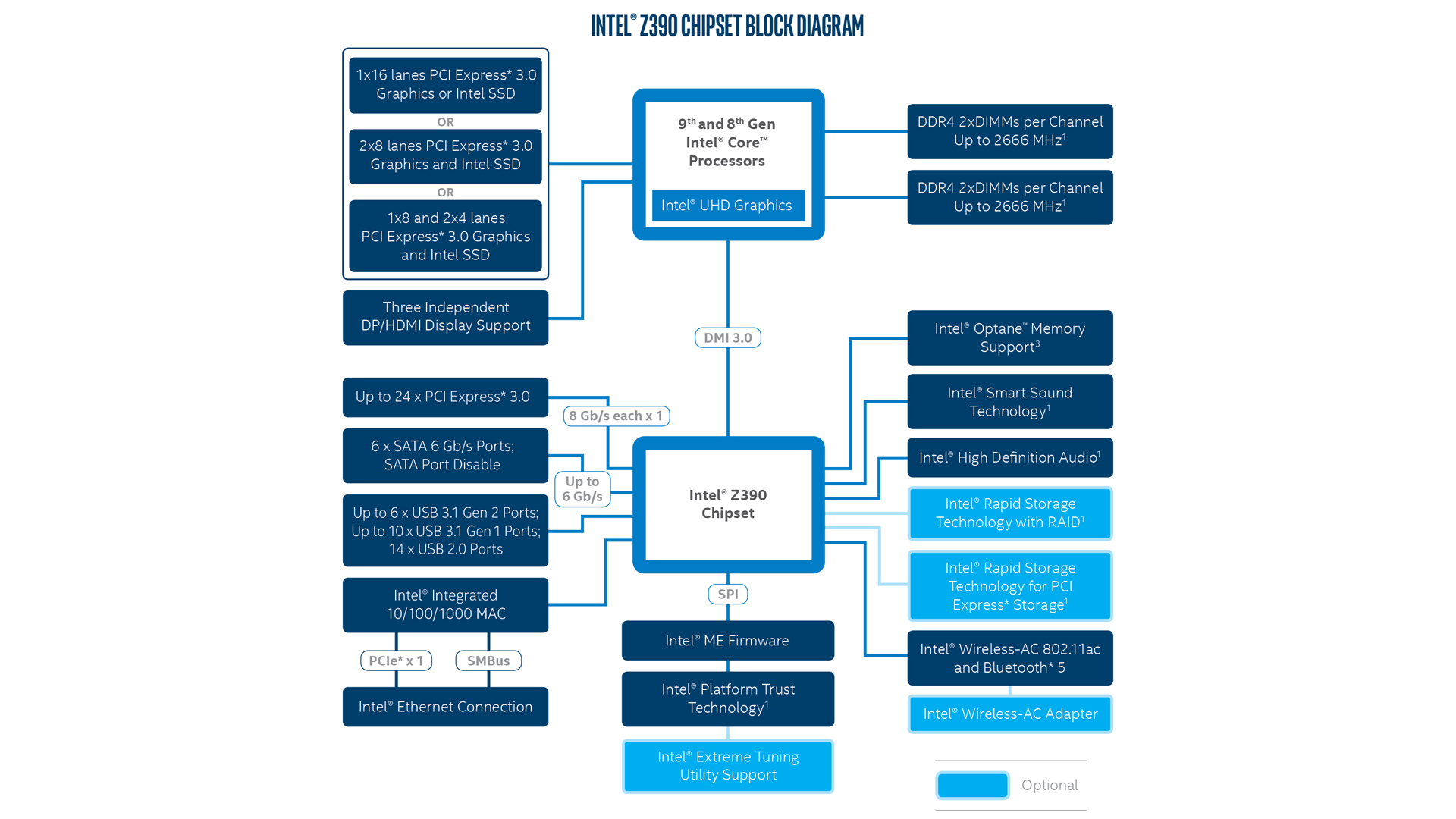
Особенности чипсета Intel Z390
Самое большое отличие чипсета Z390 от Z370 это наличие шести интегрированных портов USB 3.1 Gen 2 (10 Гбит/c).
Ещё появилась интегрированная поддержка беспроводных сетей Wi-Fi и Bluetooth, требуется только установка радио модуля с антенной, но об этом мы поговорим чуть позже.
Кроме этого, в Z390 есть встроенная поддержка протокола SDXC (SDA 3.0), для карт памяти.
Правда непонятно, как это может быть реализовано и использовано на обычных больших десктопах.
Ведь когда мы используем внешние USB картридеры, нужные протоколы, уже реализованы в их корпусах.
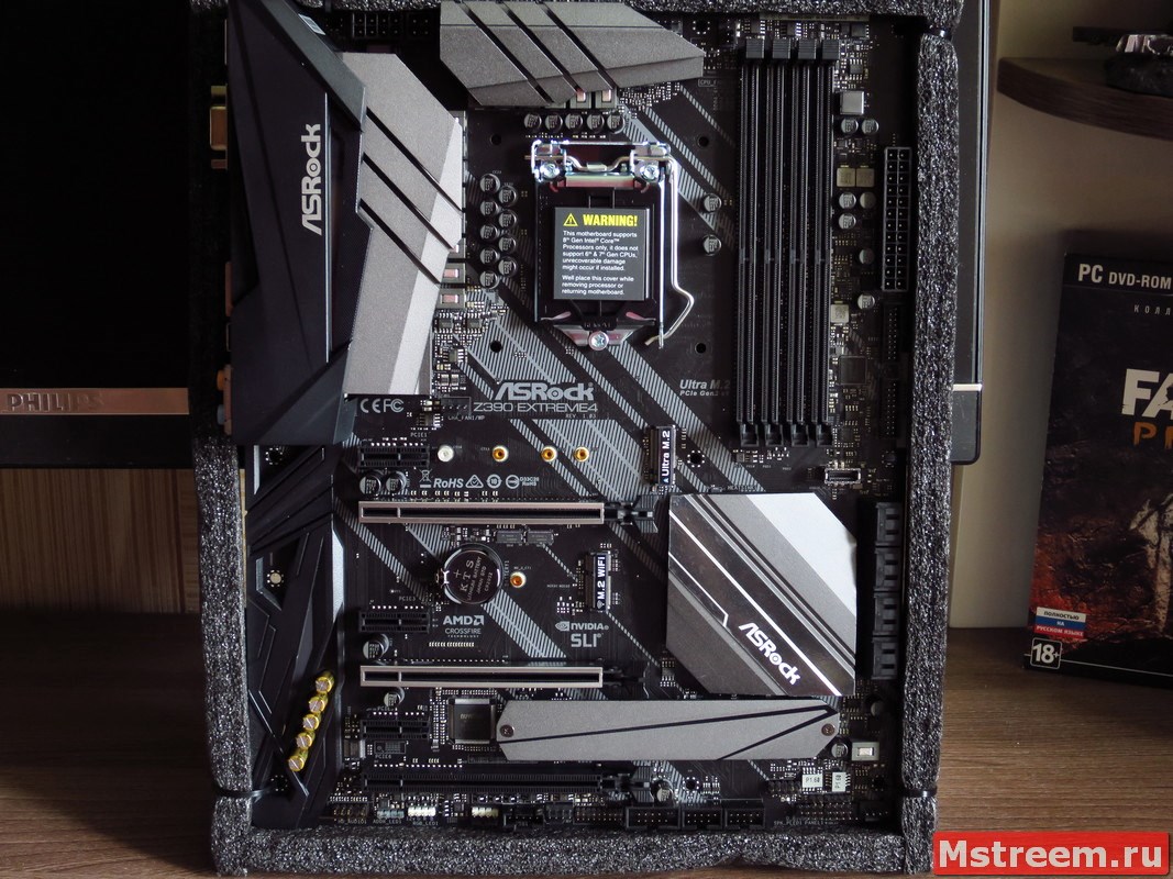
Материнская плата ASRock Z390 Extreme 4 позиционируется как довольно доступное решение на топовом чипсете Intel Z390.
Средняя стоимость материнской платы по данным сервиса Яндекс.Маркет составляет около 13.000 рублей, на момент написания данного обзора.
Материнка унаследовала практически весь основной функционал от своих старших собратьев в линейки материнских плат компании ASRock.
Текстолит имеет стандартные размеры для форм фактора ATX: 30.5 x 24.4 см.
Плата поставляется в большой красочной картонной упаковке, с удобной ручкой для переноски.
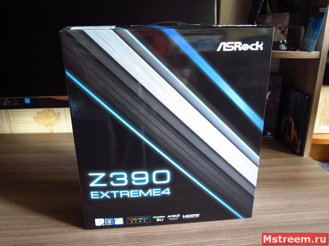
Материнская плата ASRock Z390 Extreme 4
На коробке перечислены все основные возможности и особенности материнской платы.
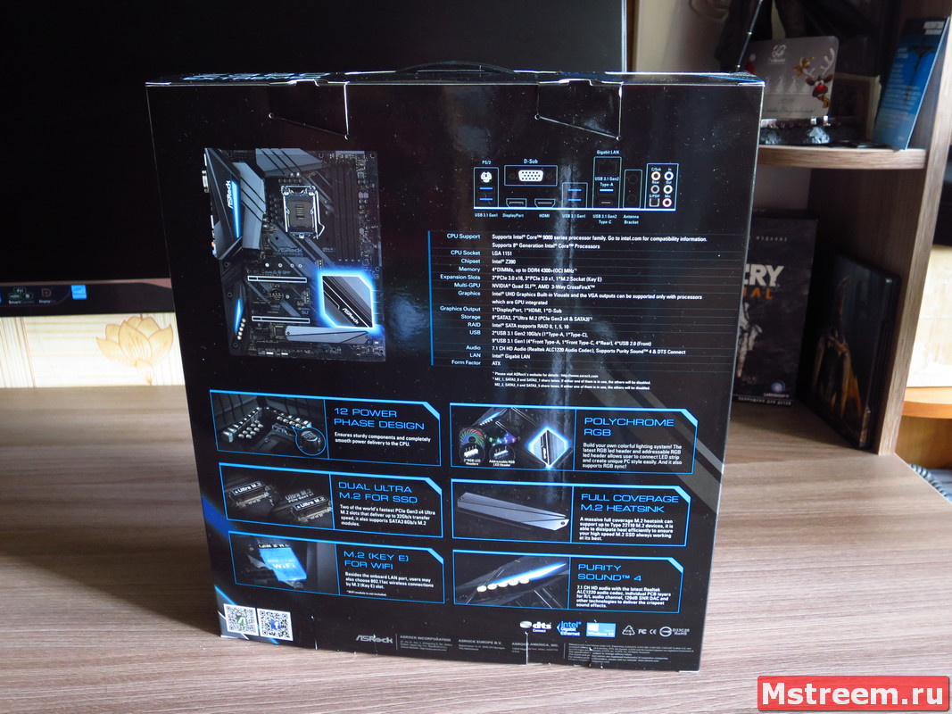
Материнская плата ASRock Z390 Extreme 4
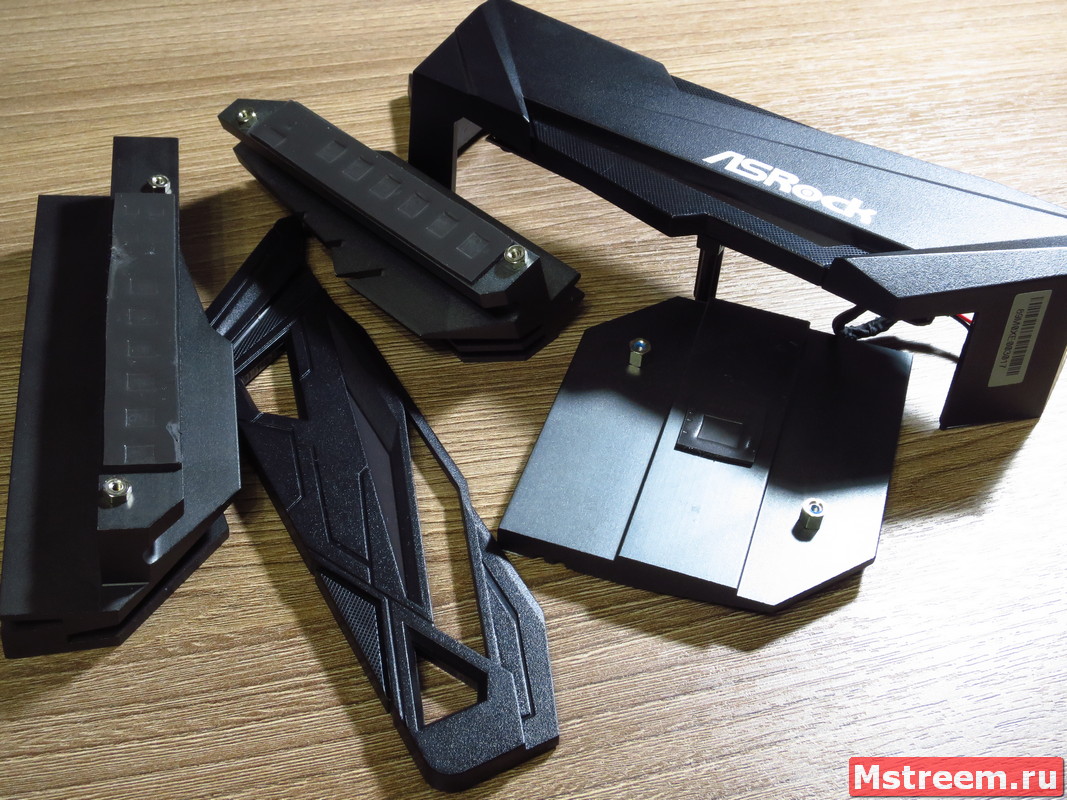
Комплект поставки, кроме самой платы включает:

Комплект поставки материнской плата ASRock Z390 Extreme 4
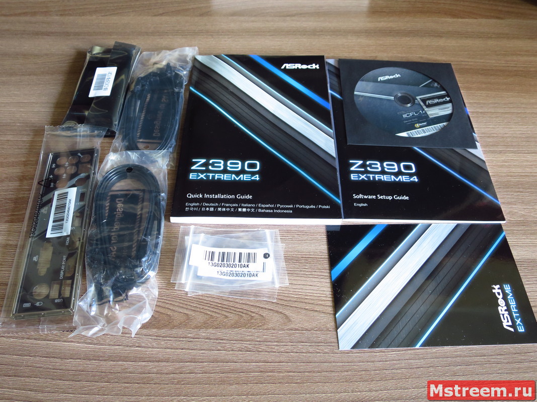
— Планку портов ввода/вывода на корпус.
— 4 SATA3.0 кабеля, для дисковой подсистемы.
— Крепёжные винты для M.2 разъёмов.
— Высокоскоростной мост Nvidia SLI для видеокарт на архитектуре Pascal.
— Диск с программным обеспечением и наклейкой ASRock.
— Руководства пользователя по материнской плате и по программному обеспечению.
— Фирменную открытку ASRock Extreme.
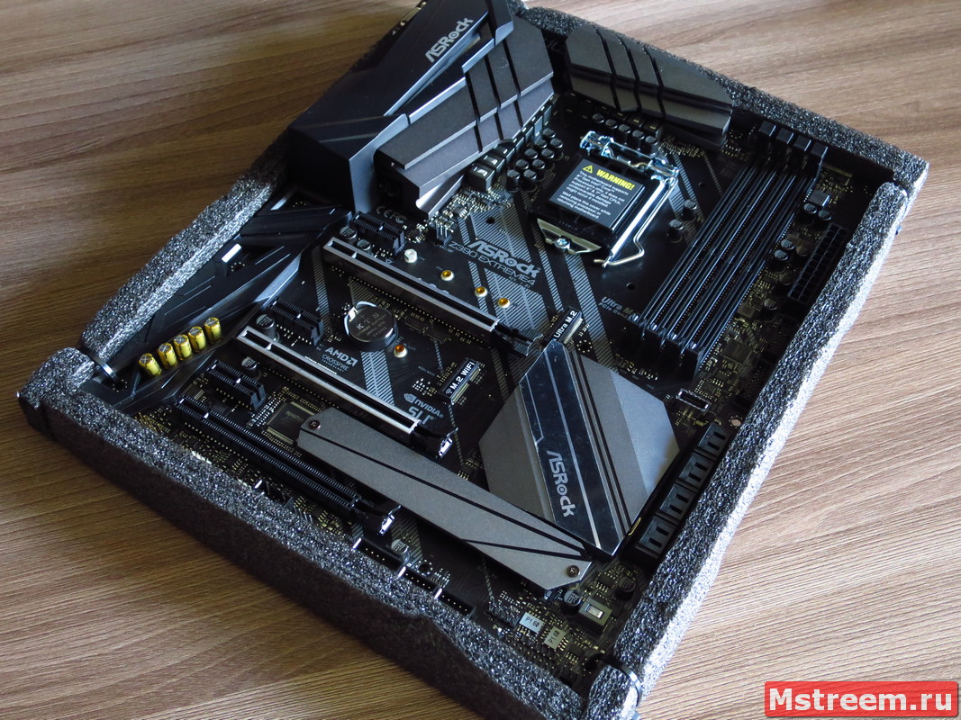
Сама плата находится на дне коробки в антистатическом пакете и надёжно закреплена стяжками на основе из вспененного материала.
Теперь давайте вместе с вами взглянем на плату более подробно.
На интерфейсной панели ввода вывода нам доступны:
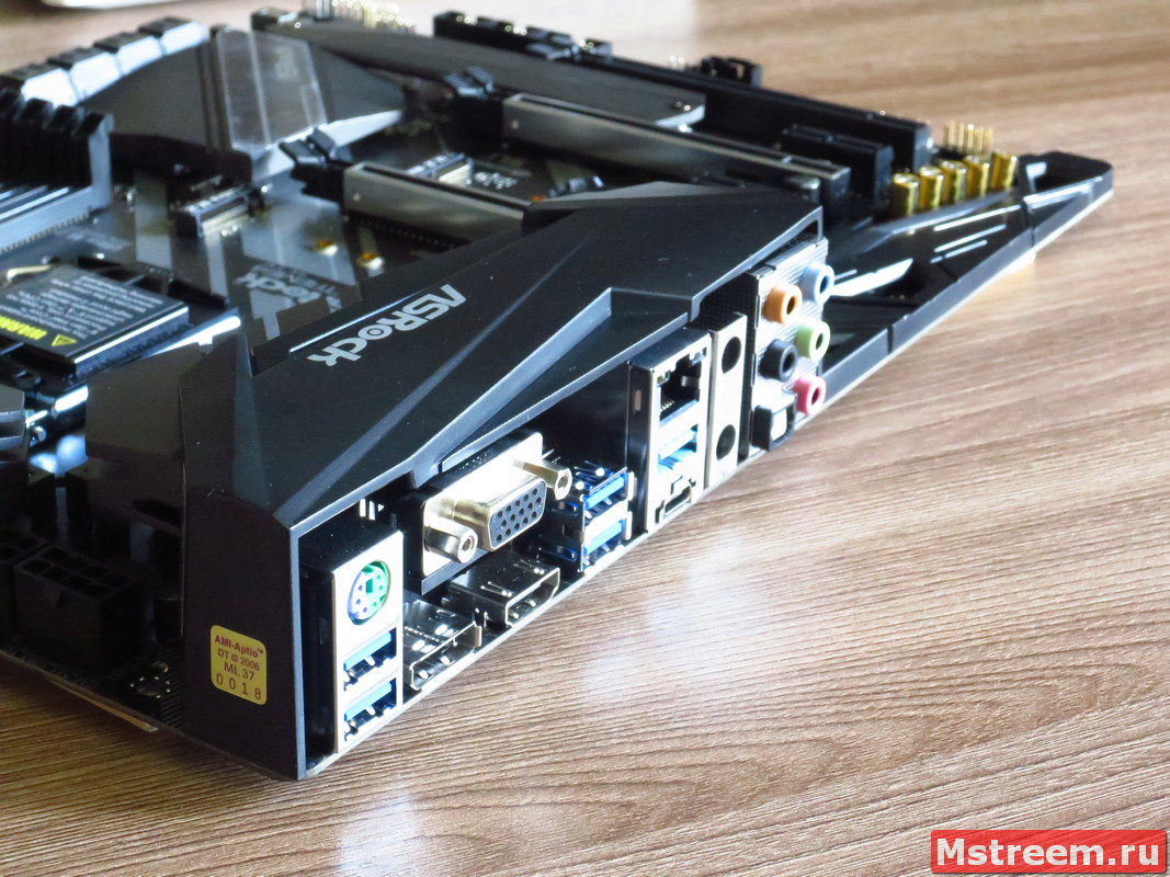
Порты ввода/вывода на материнской плате ASRock Z390 Extreme 4
— Комбинированный разъём для мыши и (или) клавиатуры PS/2.
— 4 порта USB 3.1 Gen 1 (5 Гбит/c).
— 2 порта USB 3.1 Gen 2 (10 Гбит/c), один из которых это USB Type-C.
Также на материнской плате распаяны две колодки под USB 2.0, которые в сумме дают 4 порта USB 2.0.
Кроме этого, на фронтальную панель корпуса, можно подключить ещё 4 порта USB 3.1 Gen 1 (5 Гбит/c) (реализация через контроллер USB хаба ASMedia ASM1074).
Для компьютерных корпусов с поддержкой USB Type C на фронтальной панели, также есть соответствующий порт USB Type C 3.1 Gen 1 (5 Гбит/c) который реализован силами самого чипсета Intel Z390.
— Display Port 1.2/HDMI 1.4 /D-Sub (VGA) для вывода изображения при использовании встроенной графики в процессоры Intel.
— Звуковая подсистема реализована при помощи кодека Realtec ALC1220.
Кроме аналоговых терминалов 3.5-джек также доступен и цифровой оптический SPDIF выход.
— Сетевой контроллер реализован на распространённой микросхеме Intel I219V 10/100/1000 Мб/c.
Как вы видите, на интерфейсной панели есть место под установку антенн для Bluetooth и Wi-Fi сигналов.
Если вы захотите реализовать эти беспроводные интерфейсы, вам нужно докупить отдельный модуль, который устанавливается в разъём M.2 Ключ E.
Можно было бы разместить этот разъём напротив гнёзд под антенны беспроводных интерфейсов.
Однако производитель распаял его именно тут, в центре текстолита платы.
Разъёмы для накопителей данных и PCIe:
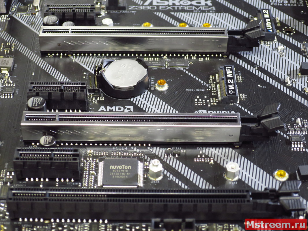
Слоты расширения и коннекторы на материнской плате ASRock Z390 Extreme 4
Порты и разъёмы на материнской плате ASRock Z390 Extreme 4
Для классических SSD и HDD предусмотрены восемь SATA портов (6 Гбит/c) с возможностью создания Raid массивов (Raid 0/1/5/10).
Шесть портов реализованы самим чипсетом Intel Z390.
Ещё два разъёма SATA работают через контроллер ASMedia ASM1061.
P.S. Самые последние два SATA порта под номерами A_1 и A_2 как раз работают через указанный контроллер.
Контроллер ASM1061 подключен к одной линии PCI Express 3.0, так что пропускной способности для двух одновременно используемых SSD в этих портах может не хватить.
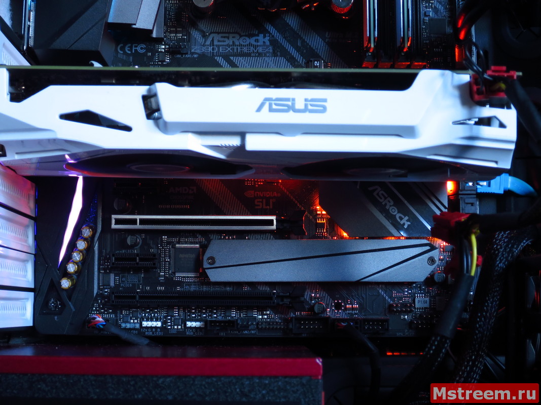
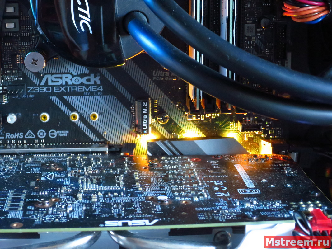
Для установки NVMe и SATA SSD накопителей предусмотрены два разъёма Ultra M.2 (32 Гбит/c).
Один разъём поддерживает накопители типоразмера до 22110, а второй до 2280.
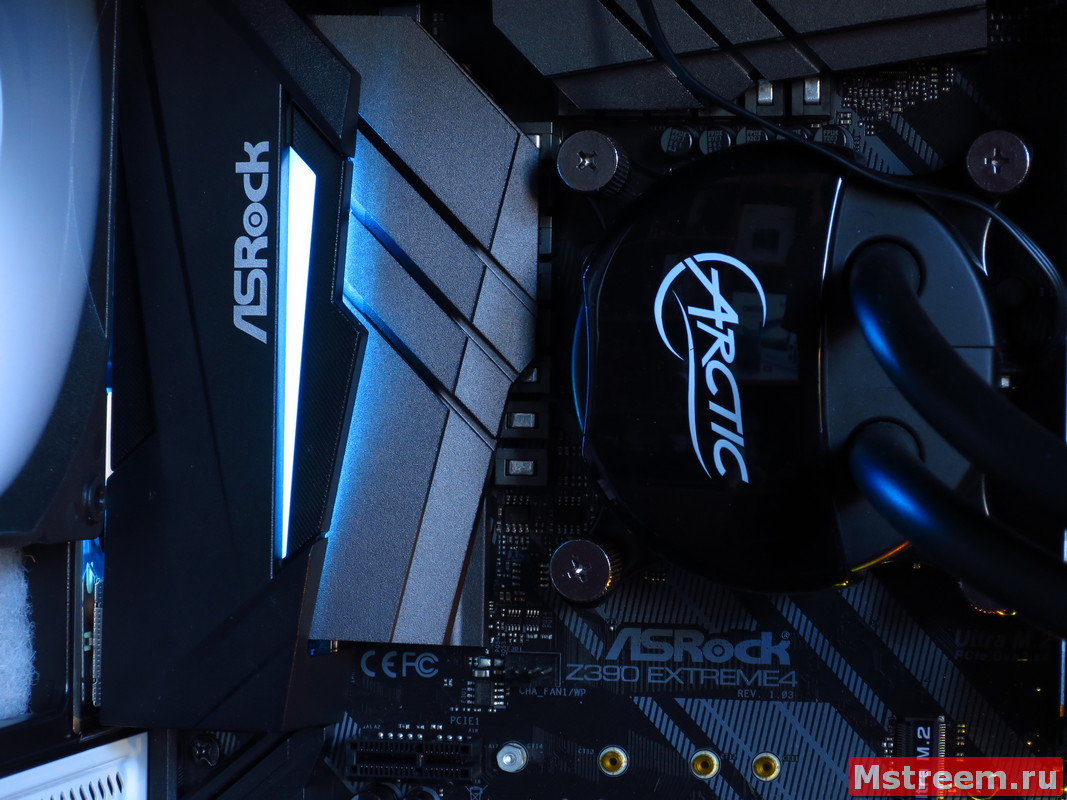
При этом материнская плата уже имеет предустановленный радиатор для охлаждения M.2 накопителя.
Дизайн материнской плате ASRock Z390 Extreme 4
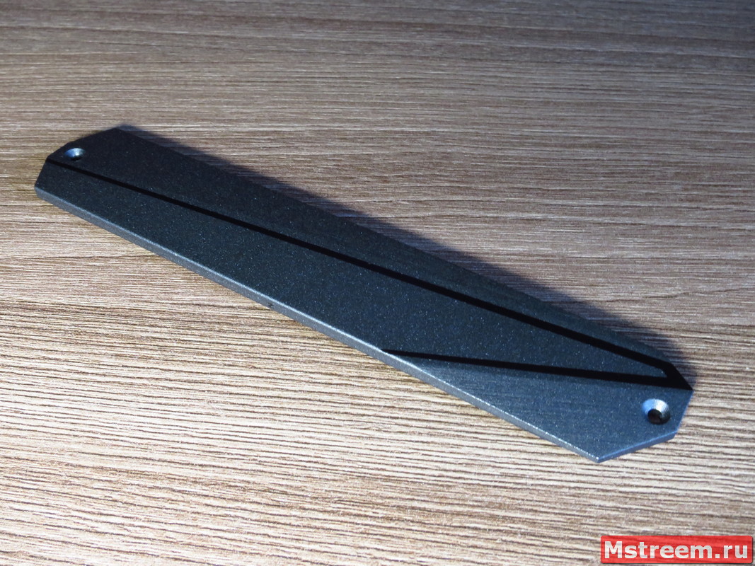
Радиатор охлаждения M.2 SSD. Материнская плата ASRock Z390 Extreme 4
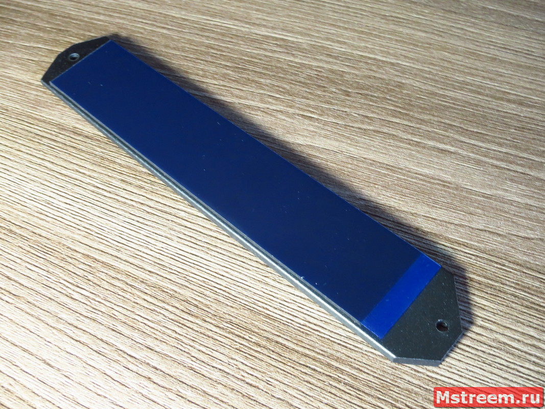
Радиатор охлаждения M.2 SSD. Материнская плата ASRock Z390 Extreme 4
P.S. SATA порты под номерами SATA3_0 и SATA3_1 имеют общие линии PCIe c разъёмом M.2_1.
Порты с номерами SATA3_4 и SATA3_5 имеют общие линии PCIe с разъёмом M.2_2.
Так что если использовать эти SATA порты, то M.2 разъёмы отключатся и соответственно наоборот.
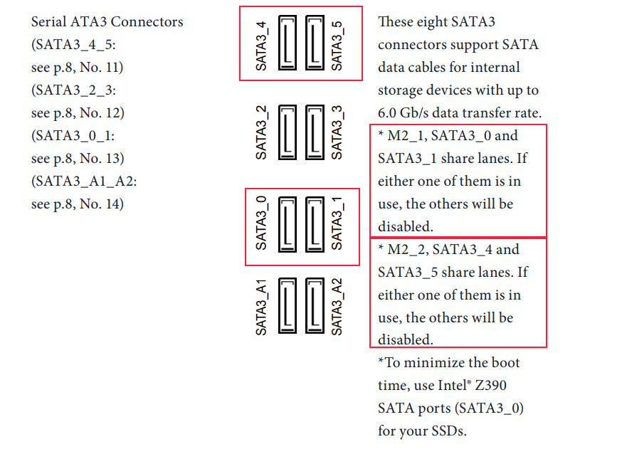
Конфигурация SATA портов и M.2 разъёмов. Материнская плата ASRock Z390 Extreme 4
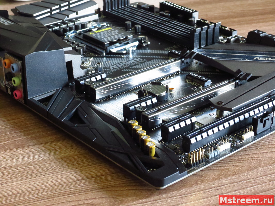
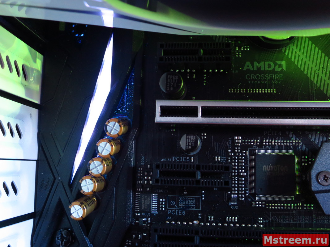
Для подключения карт расширения на чёрном текстолите материнской платы распаяны шесть портов PCI-Express 3.0.
Пластиковая основа двух полноразмерных PCIe x16 дополнительно усилена металлическим корпусом и большим количеством точек пайки.
Корпус третьего разъёма PCIe x16 выполнен из классического пластика.
Конфигурация работы полноразмерных слотов традиционная: x16/x8+x8/x8+x8+x4.
Разделение линий между разъёмами реализовано при помощи мостов (свитчей) Texas Instruments HD3SS3415.

Разделение линий PCI-Express. Материнская плата ASRock Z390 Extreme 4
Также на плате находятся ещё три разъёма PCIe x1, а один из таких разъёмов расположился над верхним PCIe x16.
Сборка компьютера на материнской плате ASRock Z390 Extreme 4
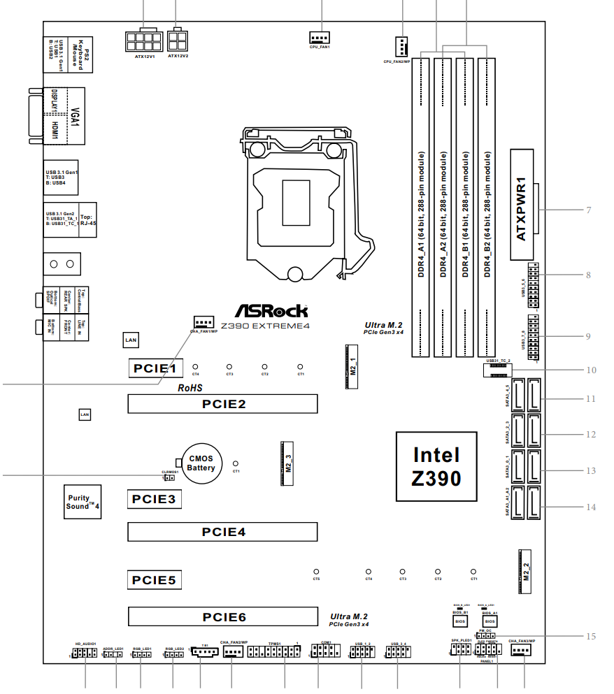
Дизайн, особенности, коннекторы и расположение основных элементов на плате:
Дизайн материнской плате ASRock Z390 Extreme 4
Дизайн материнской плате ASRock Z390 Extreme 4
Дизайн материнской плате ASRock Z390 Extreme 4
Дизайн материнской плате ASRock Z390 Extreme 4
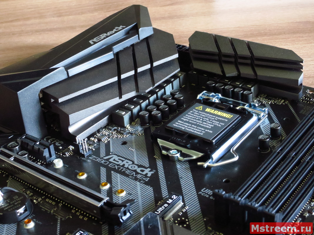
Как я и говорил ещё в начале этого обзора, материнская плата ASRock Z390 Extreme 4 позиционируется производителем как относительное доступное решение на топовом чипсете и даже для процессора с горячим нравом – Core i9 9900K.
Производитель сохранил все основные фишки и особенности присущие более дорогим и старшим решениям в своих линейках плат.
Тем не менее плата лишилась LED индикатора пост кодов, аппаратных кнопок для разгона системы (впрочем, кнопки можно подключить, есть отдельная колодка).
Также в комплекте нет радио части для встроенных контроллеров Wi-Fi и Bluetooth в самом чипсете Z390.
В чипсете встроена только цифровая часть беспроводных интерфейсов, а радио часть выполнена в виде специальной платы.
Всё это работает по протоколу CNVi (Connectivity Integration) и нужно использовать соответствующий модуль, например Intel Wireless-AC 9560.
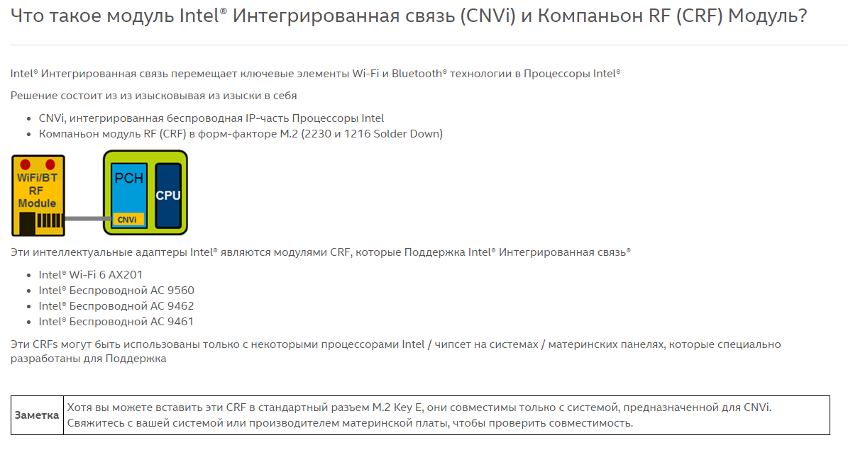
Intel CNVi модуль M.2 Wi-Fi/Bluetooth
В остальном же, как я уже и сказал плата сохранила всё самое лучшее от старших собратьев.
Для подключения корпусных вентиляторов и кулеров предусмотрены пять коннекторов.
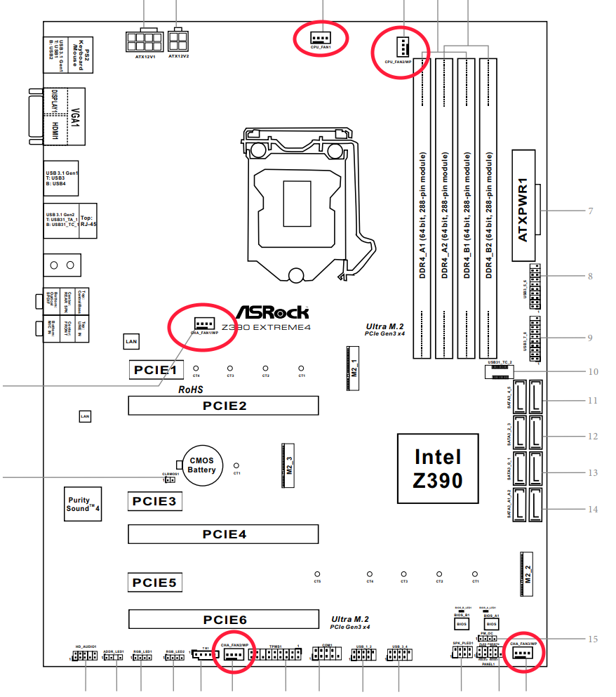
Разъёмы вентиляторов, материнская плата ASRock Z390 Extreme 4
Два расположены в верхней части платы, над разъёмом процессора.
Ещё один коннектор находится в средней части платы и два в самом низу.
Все они на 4-пин (с PWM управлением оборотов) и сразу четыре из пяти разъёмов могут работать с помпами водяного охлаждения (т.е. поддерживается увеличенный ток 2 Ампера – 24 Ватта).
Разъём CPU_FAN1 работает со стандартной мощностью 12 Ватт при токе 1 Ампер.
За управление работой коннекторов для вентиляторов ответственны контроллеры Nuvoton 3947SA.
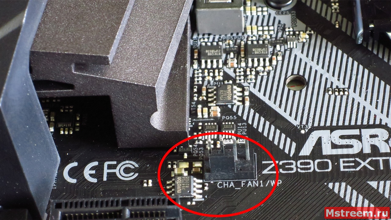
Контроллер вентиляторов. Материнская плата ASRock Z390 Extreme 4
Мультиконтроллер (Super I/O) Nuvoton NCT6791D, распаянный возле нижнего разъёма M.2 отвечает за общий мониторинг системы, а также за формирование базовых разрешительных сигналов необходимых для корректной работы системы.
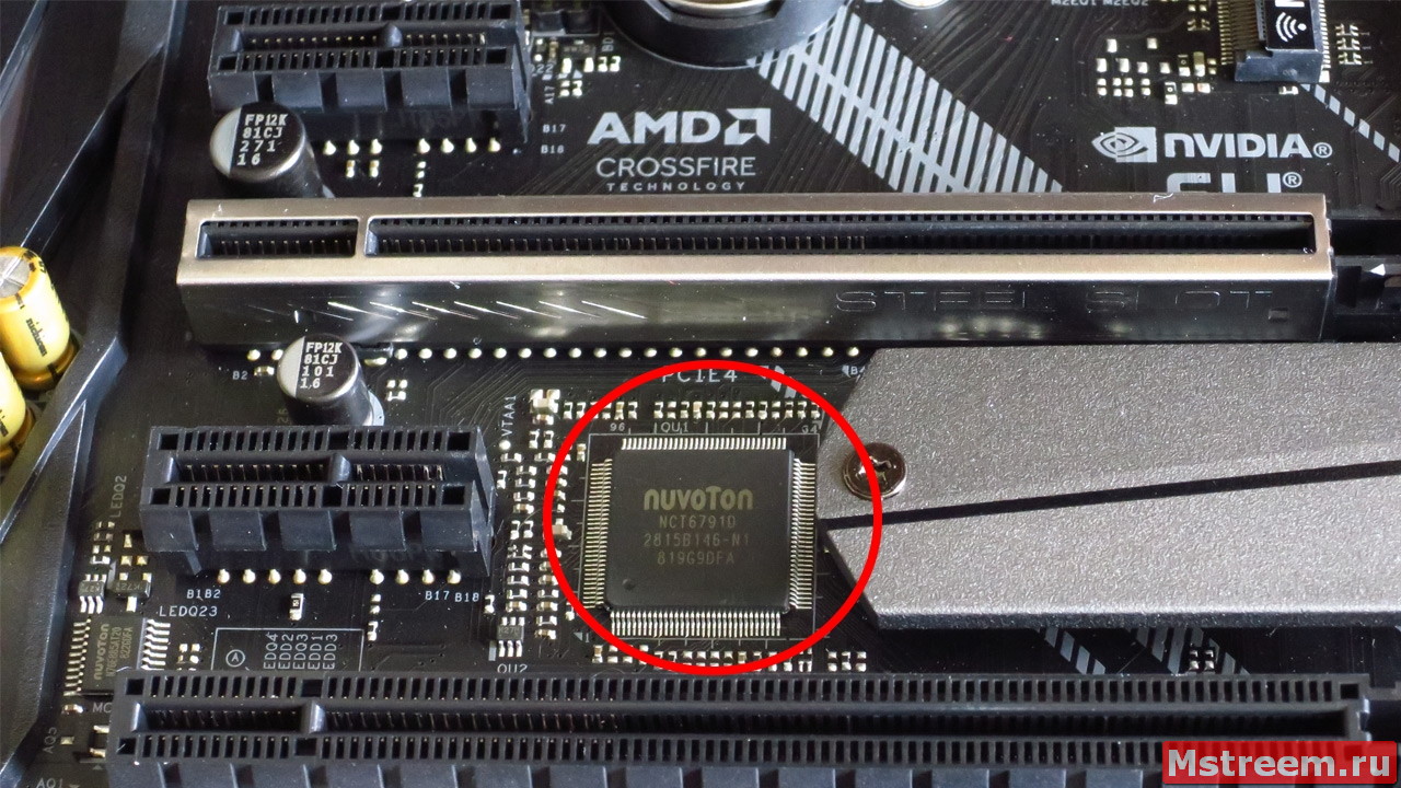
Мультиконтроллер на материнской плате ASRock Z390 Extreme 4
Разумеется, на материнской плате реализована многоцветная RGB подсветка элементов, в том числе и возможность работы со светодиодными адресными лентами.
Светиться будет зона вокруг чипсета, часть со звуковым кодеком и полоска на кожухе интерфейсной панели ввода/вывода.
Подсветка на материнской плате ASRock Z390 Extreme 4
Подсветка на материнской плате ASRock Z390 Extreme 4
Подсветка на материнской плате ASRock Z390 Extreme 4
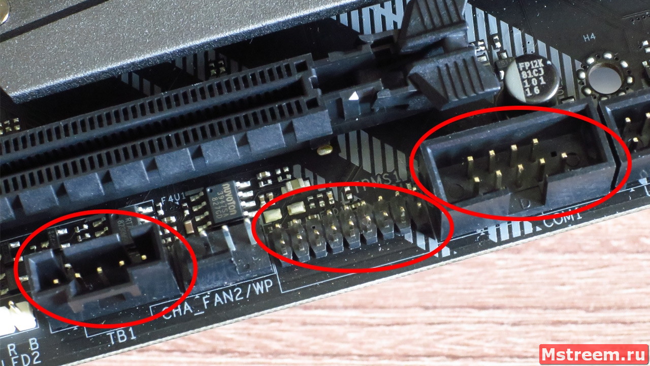
Разъёмы для подключения светодиодных лент находятся в нижней части платы.
За работу светодиодных лент отвечает микроконтроллер Nuvoton N76E885AT20.
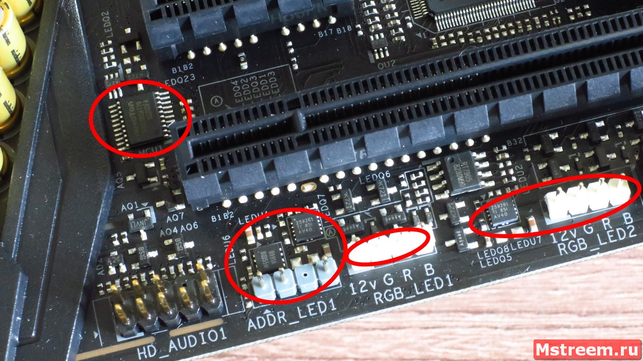
Подсветка на материнской плате ASRock Z390 Extreme 4
Также в обвязке цепи коннекторов RGB применены микросхемы защиты Texas Instruments TPS256261.
Два разъёма, на 4 контакта (RGB_LED1) рассчитаны на использование стандартных лент с напряжением питания в 12 Вольт.
Разъём 3-пин ADDR_LED1 предназначен для работы с адресной светодиодной лентой.
P.S. Будьте внимательны и не подключайте адресную ленту в обычный разъём RGB 12V!
Такие ленты питаются напряжением 5 Вольт и будут повреждены при подключении в стандартный разъём на 12 Вольт!
Управлять всей подсветкой можно через фирменное приложение ASRock Polychrome Sync.
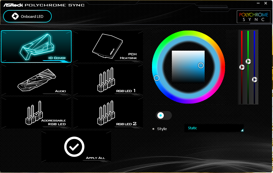
RGB Подсветка ASRock Polychrome Sync
Здесь выбираются различные эффекты подсветки, а также есть возможность управлять подсветкой индивидуально, для каждого элемента материнской платы.
Также в нижней части платы можно увидеть 5-и пиновый коннектор Thunderbolt AIC для подключения отдельной карты расширения с соответствующими портами.
Ещё один коннектор — это так называемый TPM Header, опциональный модуль безопасности и криптографии.
Не остался забыт и старый добрый COM порт (RS232), так что, если требуется его можно без проблем использовать.
Дополнительные колодки на материнской плате ASRock Z390 Extreme 4
Реализован он с помощью микросхемы BSD AZ75232, которая распаяна на обратной стороне текстолита платы.
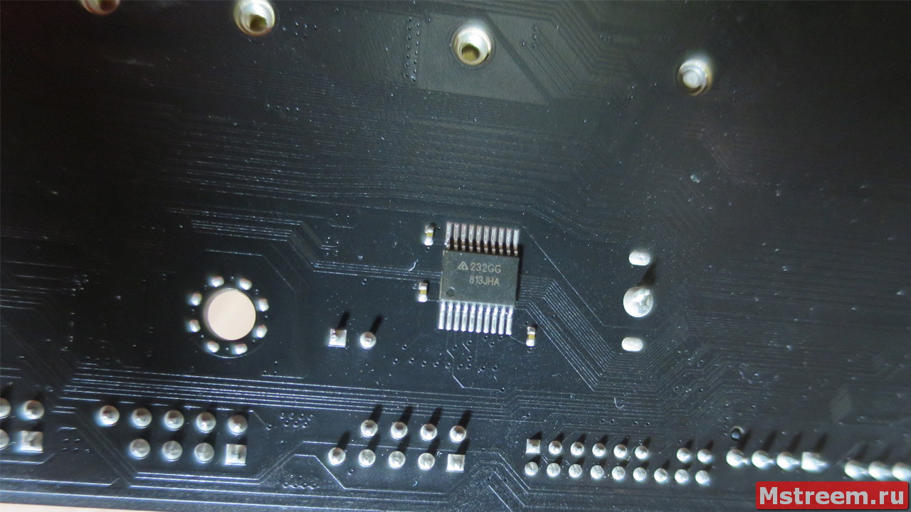
RS-232 на материнской плате ASRock Z390 Extreme 4
Над коннекторами под динамик (speaker) и подключения корпусных кнопок и светодиодов находится ещё один коннектор.
Он 4-ёх пиновый и служит для подключения опциональных кнопок для автоматического разгона системы (Easy OC).
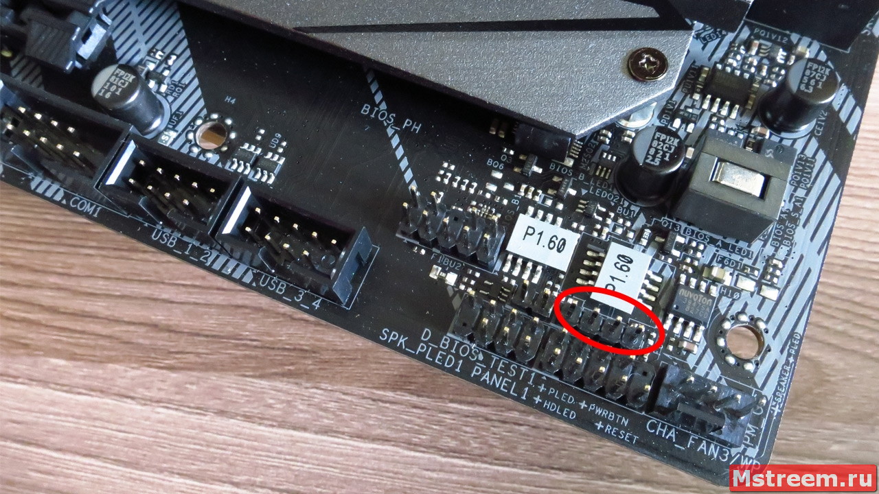
Подключение кнопок Easy OC на материнской плате ASRock Z390 Extreme 4
Напомню, что соответствующих аппаратных кнопок на материнской плате не распаяно.
P.S. Назначение двух штырьков рядом с этим коннектором мне неизвестно.
Также есть ещё одна колодка внешне похожая на USB 2.0, однако это не она, а её назначение также неизвестно.
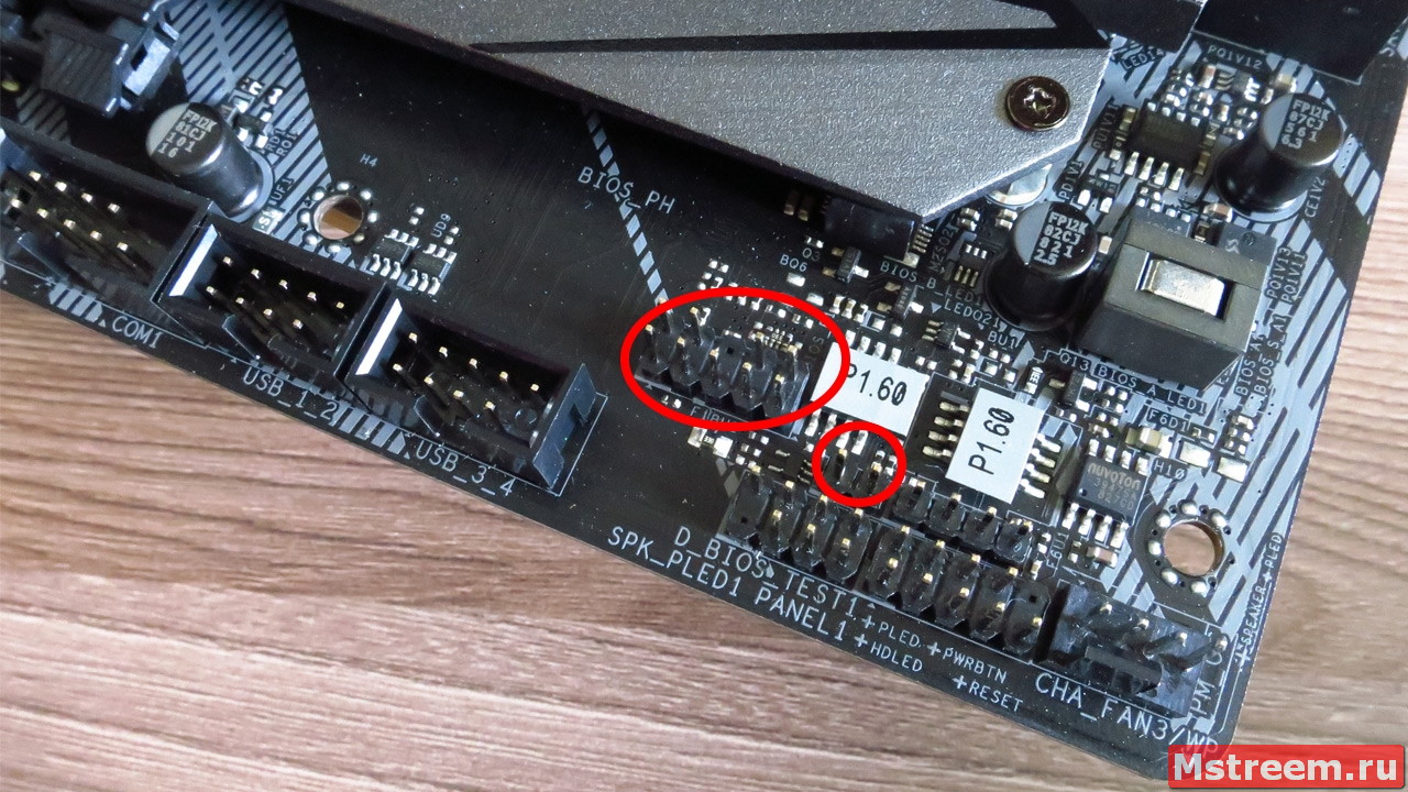
Неизвестные колодки на материнской плате ASRock Z390 Extreme 4
Теперь давайте посмотрим на правую часть материнской платы ASRock Z390 Extreme 4.
Возле слотов оперативной памяти расположены два коннектора на 19-пин, каждый из которых позволяет реализовать по два порта USB 3.1 Gen 1 (5 Гбит/c).
Для удобства хотелось бы, чтобы эти два разъёма были угловыми.
Работа сразу же с четырьмя портами возможна благодаря крупной микросхеме USB хабу ASMedia ASM1074.
А за работу фронтального USB Type-C коннектора отвечает контроллер ASMedia ASM1543.
Между этими двумя контроллерами расположена микросхема флеш памяти, в которой очевидно находится управляющая микропрограмма, это Winboard 25X10CLNIG.
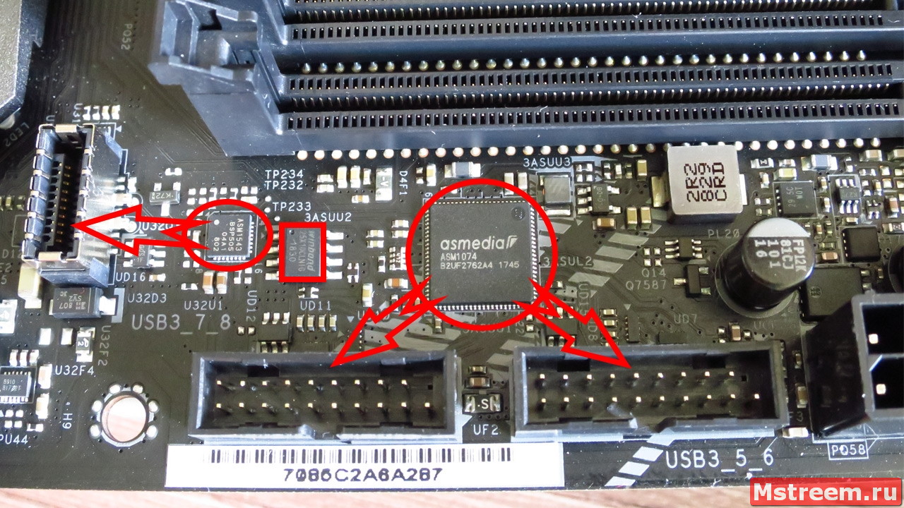
Дополнительные USB порты на материнской плате ASRock Z390 Extreme 4
В обвязке цепи питания оперативной памяти применён однофазный шим контроллер Richtek RT8120, а также N-канальные MOSFET транзисторы Sinopower SM4337.
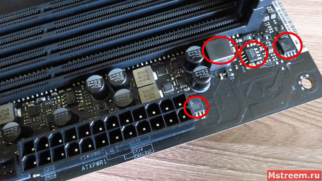
Питание оперативной памяти на материнской плате ASRock Z390 Extreme 4
В качестве конденсаторов используются высококачественные японские Nichicon 12K Black.
Если снять радиатор охлаждения чипсета Intel Z390, то можно увидеть микросхему ASMedia ASM1061, которая реализует работу двух SATA портов.
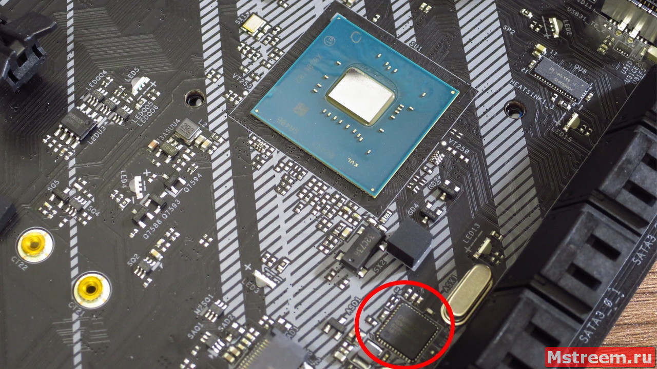
Дополнительные SATA порты на материнской плате ASRock Z390 Extreme 4
P.S. Традиционно радиатор крепится с помощью подпружиненных винтов, а контакт с кристаллом чипсета осуществляется при помощи термопрокладки.
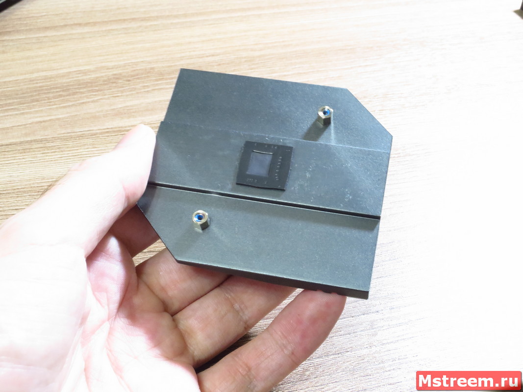
Охлаждение чипсета на материнской плате ASRock Z390 Extreme 4
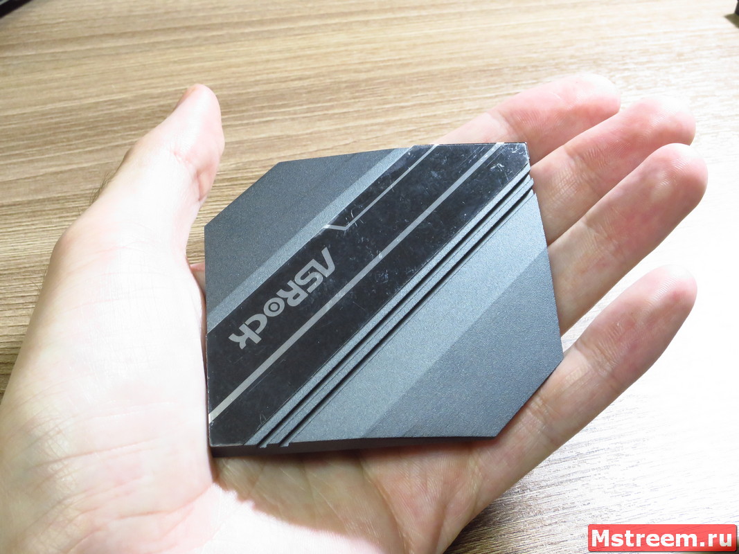
Охлаждение чипсета на материнской плате ASRock Z390 Extreme 4
Теперь давайте снимем пластиковую рамку, которая закрывает всю боковую часть платы и область возле звукового кодека.
Звуковая подсистема основана на кодеке от Realtec ALC1220, а для усилительной части используется операционный усилитель Texas Instruments NE5532.
В обвязке также используются высококачественные японские конденсаторы Nichicon Fine Gold.
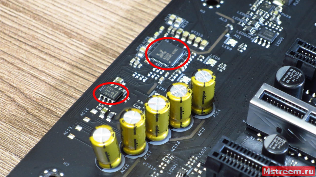
Звуковая подсистема на материнской плате ASRock Z390 Extreme 4
Сам звуковой тракт физически отделён от других слоёв печатной платы, а для левого и правого звуковых каналов используются отдельные слои текстолита.
Всё это в теории позволяет исключить любые паразитные наводки на звуковую подсистему материнской платы.
При использовании фирменного программного обеспечения можно поэкспериментировать со звуком, с помощью эквалайзера и других предустановленных параметров.
Если снять второй пластиковый кожух, обрамляющий интерфейсную панель ввода/вывода, то перед нами открываются микросхемы:
Intel I219V отвечающая за сеть, ASMedia ASM1442K отвечающая за реализацию HDMI, а также Realtec RTD2168, которая позволяет работать с D-sub (VGA) видео разъёмом и ASMedia ASM1543, которая реализует пор USB Type-C.
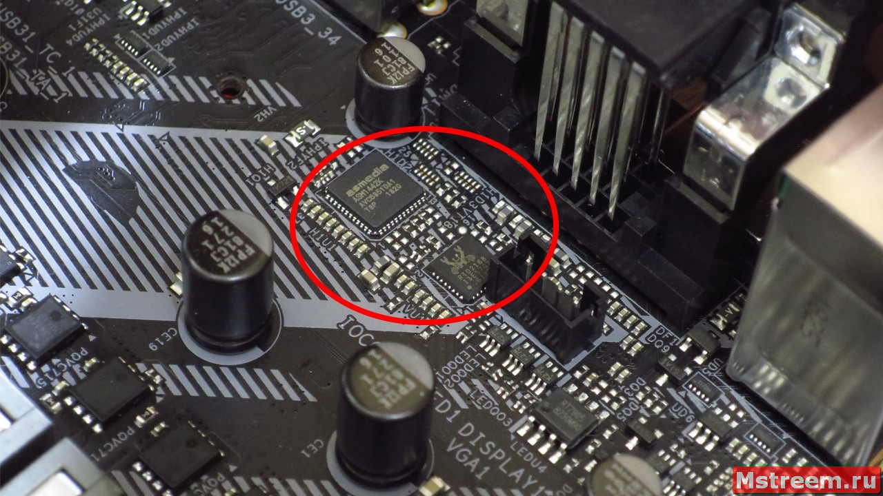
Микроконтроллеры на материнской плате ASRock Z390 Extreme 4
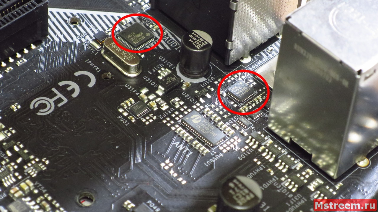
Микроконтроллеры на материнской плате ASRock Z390 Extreme 4
Подсистема питания процессора:
Что же друзья, теперь мы с вами подошли к самому интересному моменту обзора.
Разберём из каких же элементов состоит подсистема питания центрального процессора.
Для подпитки процессора используются два коннектор ATX12V 8+4 пин.

Питание процессора на материнской плате ASRock Z390 Extreme 4
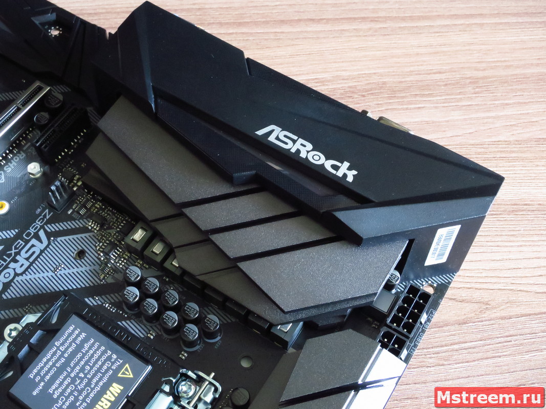
Система охлаждения цепей питания состоит их двух независимых друг от друга довольно крупных радиаторов.
В старших же решениях ASRock, эти радиаторы соедини теплотрубками.
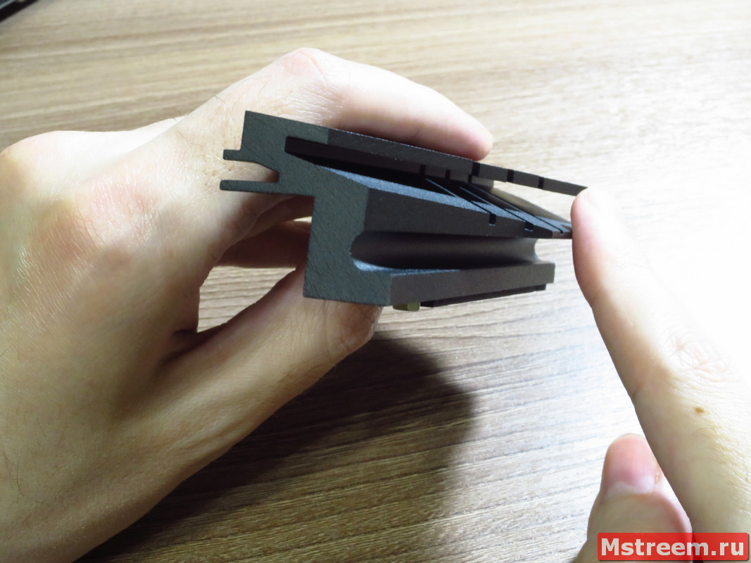
Радиаторы охлаждения цепей питания на материнской плате ASRock Z390 Extreme 4
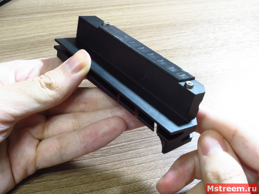
Радиаторы охлаждения цепей питания на материнской плате ASRock Z390 Extreme 4
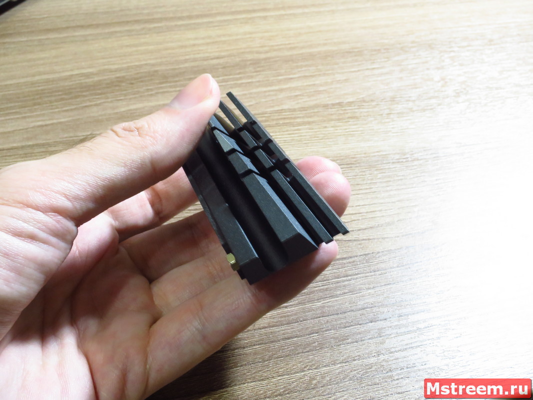
Радиаторы охлаждения цепей питания на материнской плате ASRock Z390 Extreme 4
Радиаторы охлаждения цепей питания на материнской плате ASRock Z390 Extreme 4
Мы обязательно посмотрим, как это скажется на температурах VRM.
Радиаторы крепятся при помощи подпружиненных винтов, а тепло от элементов схемы передаётся посредством термопрокладок.
Сами радиаторы выглядят внушительно и имеют многочисленные каналы и рёбра для более эффективного рассеивания тепла от мощной подсистемы питания.
Процессорный разъём обрамляют целых 14 дросселей, а в качестве силовых элементов используются мощные MOSFET транзисторы Sinopower SM7341EHKP в количестве 12-и штук (каждый рассчитан на ток в 24А).
Подсистема питания центрального процессора на материнской плате ASRock Z390 Extreme 4
Также в схеме используются японские конденсаторы Nichicon 12K Black.
Шим контроллером выступает микросхема производства Sinopower uP9521P, и вот тут начинается самое интересное.
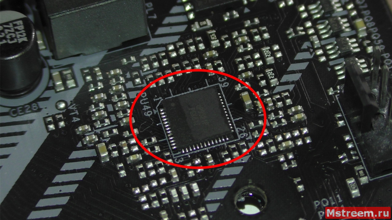
ШИМ контроллер подсистемы питания Sinopower uP9521P. Материнская плата ASRock Z390 Extreme 4
Я нашёл даташит только на обычный Sinopower uP9521 без буквы P, который по документации работает с двумя каналами по схеме 4+3 фазы (либо можно реализовать 4+2).
Контроллер же с буквой P попросту не находится на официальном сайте компании Sinopower.
То есть шим контроллер без буквы P может в сумме управлять максимум семью фазами.
4 фазы для питания CPU (Vcore) и ещё 3 фазы для питания графического ядра процессора (VccGT).
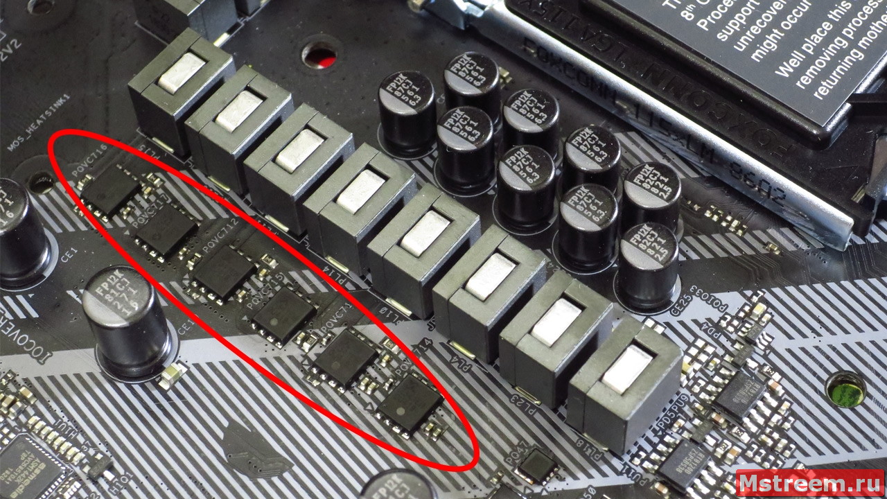
На обратной стороне материнской платы распаяны сразу же семь внешних драйверов UPI Semiconductor – два UP1962 и пять UP1965.
Очевидно, что два драйвера UP1962 управляют двумя фазами питания встроенного графического ядра в процессор Intel.
Таким образом два транзистора Sinopower SM7341EHKP и две катушки отвечают за встроенную графику.
Оставшиеся пять драйверов UP1965 работают с фазами питания центрального процессора.
То есть получается, что шим контроллер Sinopower uP9521p всё-таки работает по схеме 5+2 фазы в двух каналах.
В пяти фазах для процессора используется удвоенное количество элементов на фазу (то есть по две катушки и по два транзистора на 24 Aмпера каждый).
В сумме получается, что на фазы CPU уходит 10 катушек и 10 транзисторов.
Система питания процессора на материнской плате ASRock Z390 Extreme 4
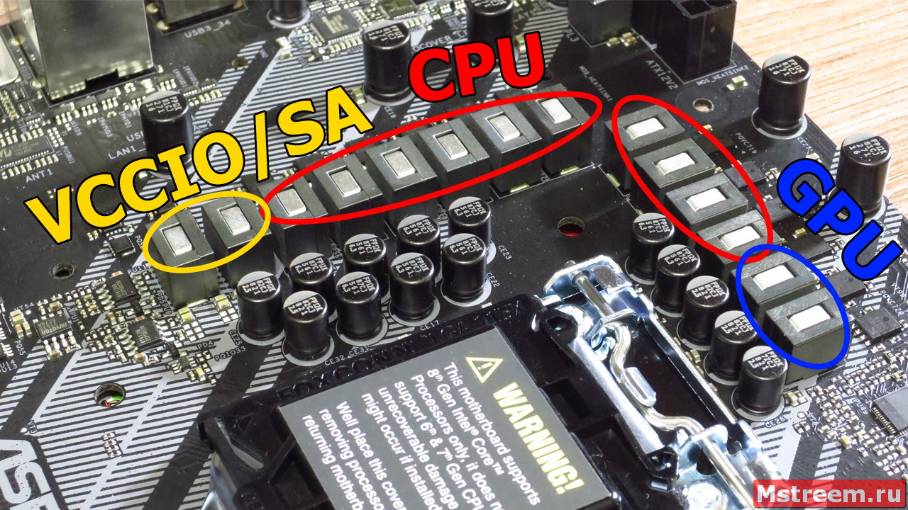
Оставшиеся две фазы отвечают за питание VCCSA и VCCIO (то есть за питание системного агента и контроллера оперативной памяти).
В этой схеме применены два одноканальных однофазных шим контроллера Richtek RT8120 на каждую фазу.
В качестве транзисторов используются четыре транзистора Advanced Power Electronics AP4034GYT, на 15.5 Ампер каждый.

Система питания процессора на материнской плате ASRock Z390 Extreme 4
Таким образом подсистема питания центрального процессора довольно мощная, так что думаю, что она позволит работать даже с топовым Core i9 9900K на 8 ядер, в стоке уж точно.
Теперь давайте посмотрим на температуры цепей питания при разгоне процессора Intel Core i5 8600K.
Увы, к сожалению, у меня в наличии есть только такой процессор.
<Разгон процессора, температуры подсистемы питания и BIOS:
На материнской плате ASRock Z390 Extreme 4 установлен UEFI версии 1.60.
UEFI на материнской плате ASRock Z390 Extreme 4
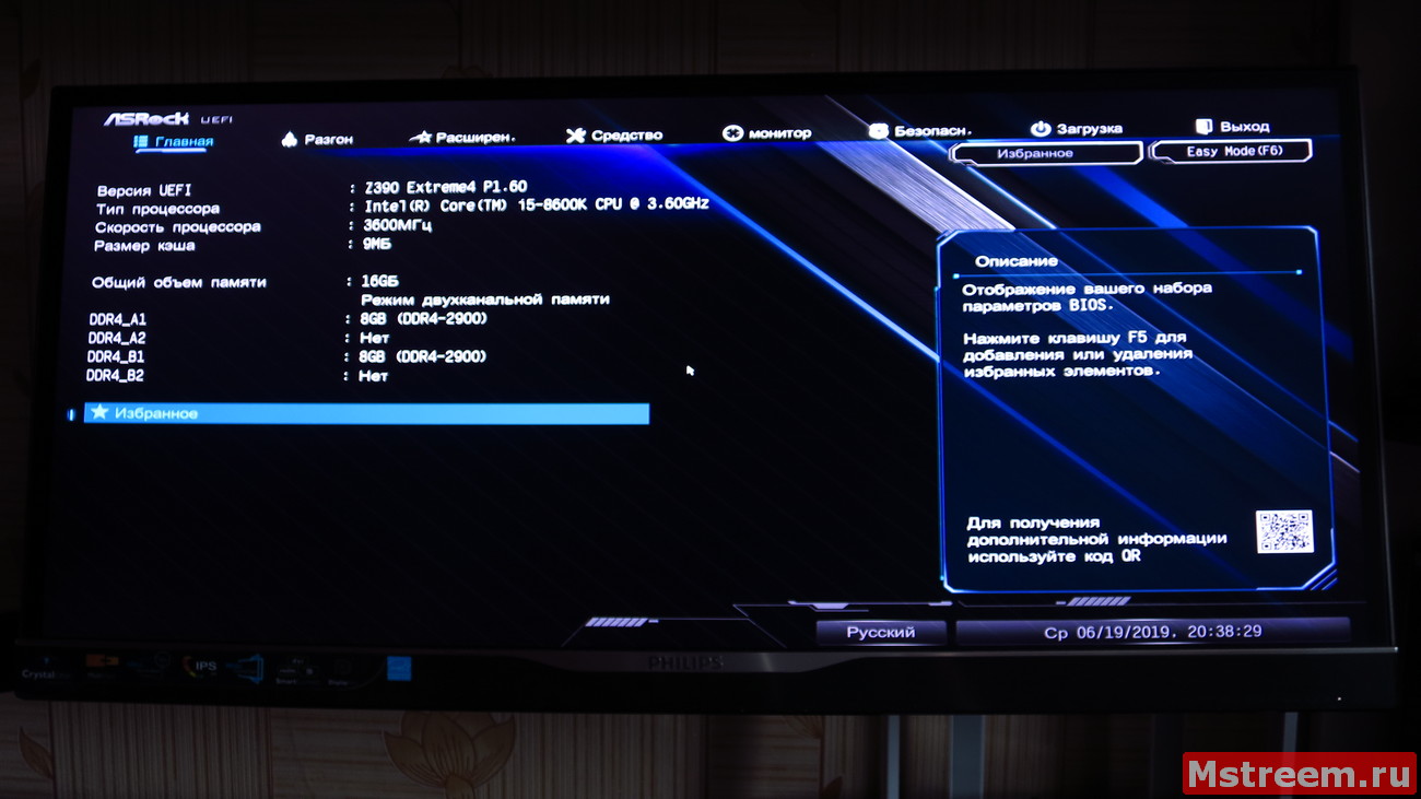
UEFI на материнской плате ASRock Z390 Extreme 4
Существуют куда более свежие версии UEFI прошивки, однако даже версия 1.60 обеспечивает стабильную работу системы и хороший разгонный потенциал.
На UEFI я не буду слишком останавливаться, поскольку он имеет точно такой же внешний и логический вид, как у всех современных материнских плат ASRock.
Единственное отличие — это синяя цветовая гамма, которая олицетворяет Extreme серию материнских плат.
Однако основные возможности я конечно же рассмотрю и покажу.
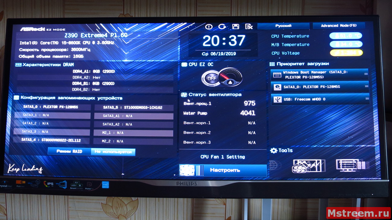
Управление вентиляторами осуществляется в разделе «Монитор».
Тут можно перевести вентиляторный разъём в режим работы с помпой водяной системы охлаждения процессора – W_PUMP.
Регулировать обороты помпы можно при помощи PWM сигналов или при помощи изменения напряжения DC Mode, если помпа трёхпиновая.
Для CPU_FAN1 в качестве источника температуры логично доступен только центральный процессор. Вы можете выбирать температуры и обороты вентиляторов в зависимости от них.
Для остальных вентиляторов в качестве источника температур можно выбирать либо процессор, либо датчик температуры материнской платы.
Также 4 разъёма могут работать с водяными помпами благодаря повышенному току отдачи до 2 Ампер.
Теперь перейдём к настройкам центрального процессора.
Для разгона CPU нужно воспользоваться пунктом «Разгон»-«Конфигурация ЦП».
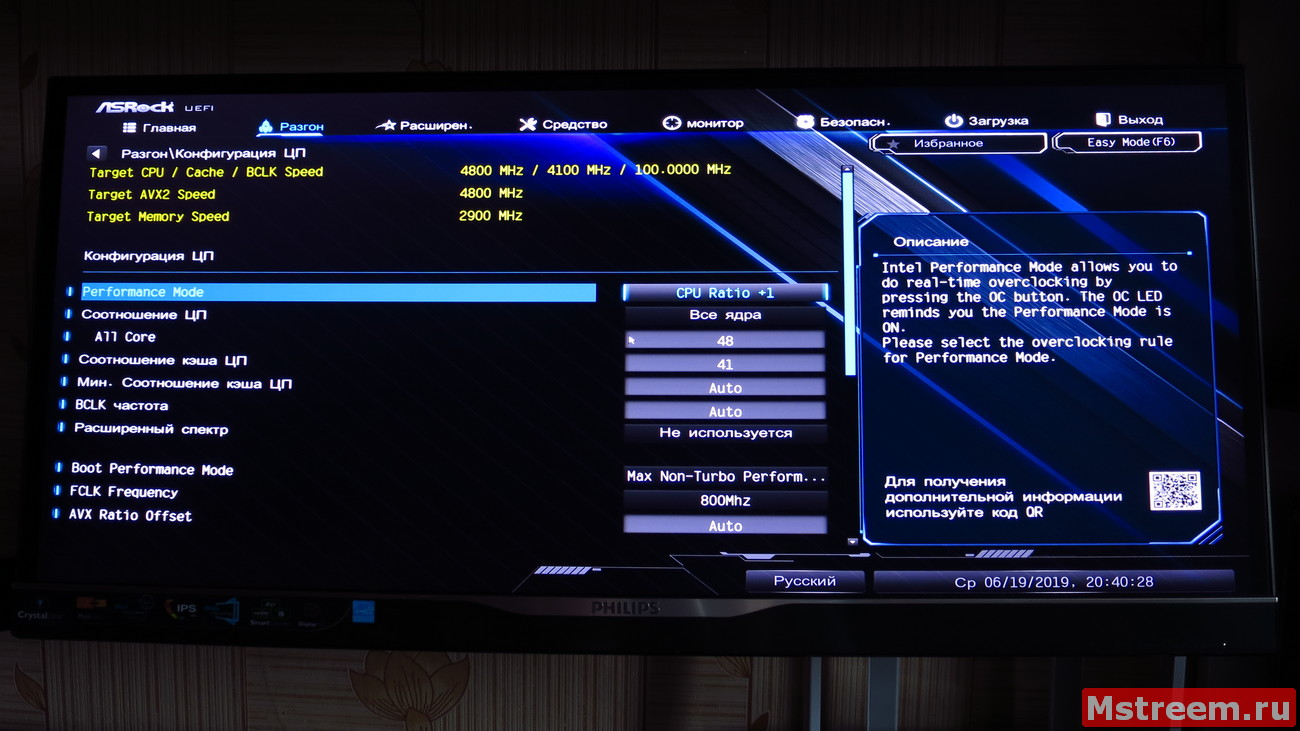
Разгон процессора Intel на материнской плате ASRock Z390 Extreme 4
В этом разделе можно управлять множителями ядер центрального процессора, множителем кеша, частотой BCLK шины, а также опциями энергосбережения и так далее.
P.S. Опция Perfomance Mode отвечает за работу опциональных кнопок (которые подключаются к соответствующей колодки на материнской плате) для разгона системы.
По умолчанию нажатие такой кнопки повысит множитель процессора на единицу.
AVX Ratio Offset отвечает за снижение рабочий частоты процессора при активном выполнении AVX инструкций.
Процессор Intel Core i5 8600K я буду разгонять до частоты 4.8 ГГц, то есть я выставляю множитель 48 для всех ядер процессора, а множитель кеша на 41, что позволит внутренней шине процессора работать на частоте 4.100 МГц.
Всё управление напряжениями происходит в отдельном разделе «Разгон»-«Конфигурация напряжений».
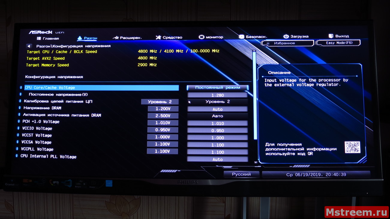
Разгон процессора Intel на материнской плате ASRock Z390 Extreme 4
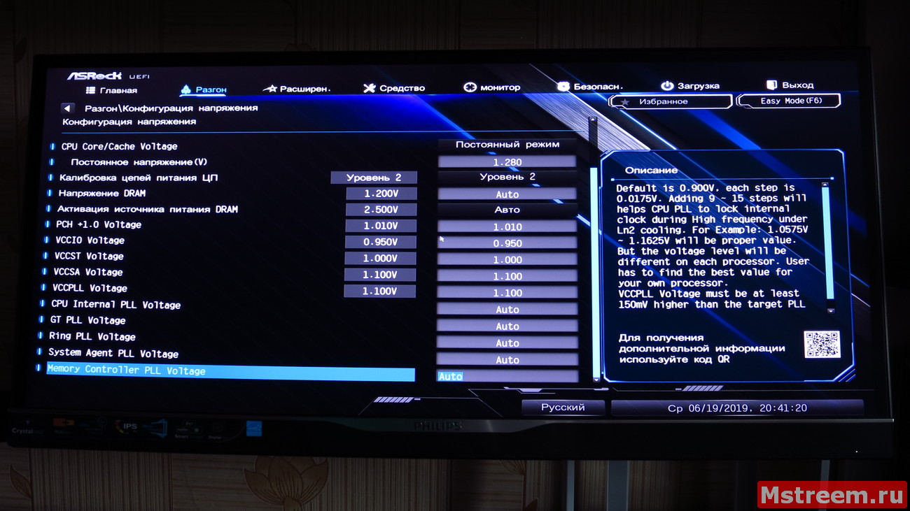
Разгон процессора Intel на материнской плате ASRock Z390 Extreme 4
Для конфигурации питающего напряжения ядер центрального процессора предусмотрены два режима.
Установка со смещением в милливольтах и постоянный режим напряжения.
Я выбираю второй вариант установки напряжения – «Постоянный режим».
Для частоты процессора 4.8 ГГц – я выставляю напряжение процессора в 1.280 Вольта, а уровень калибровки цепей питания на второй уровень.
Также мы можем управлять важными вторичными напряжениями VCCIO/VCCSA/VCCST/VCCPLL/PCH/GTPLL/RingPLL/System Agent PLL и Memory Controller PLL.
Оперативная память GoodRam Iridium (две планки по 8 Гб) со своей базовой частоты 2400 МГц (тайминги 15-15-15-39) была разогнана до частоты 2900 МГц (тайминги 17-17-17-40).
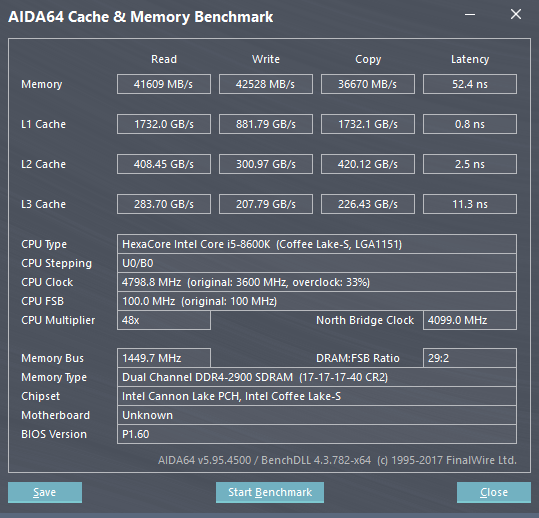
Разгон оперативной памяти и процессора Intel на материнской плате ASRock Z390 Extreme 4
Для удобства пользователя система предоставляет возможность сохранить до пяти профилей со всеми сделанными вами настройками в UEFI (опция доступна на главной странице «Разгон»).
Теперь пришло время сохранить все манипуляции с напряжениями и с множителями процессора.
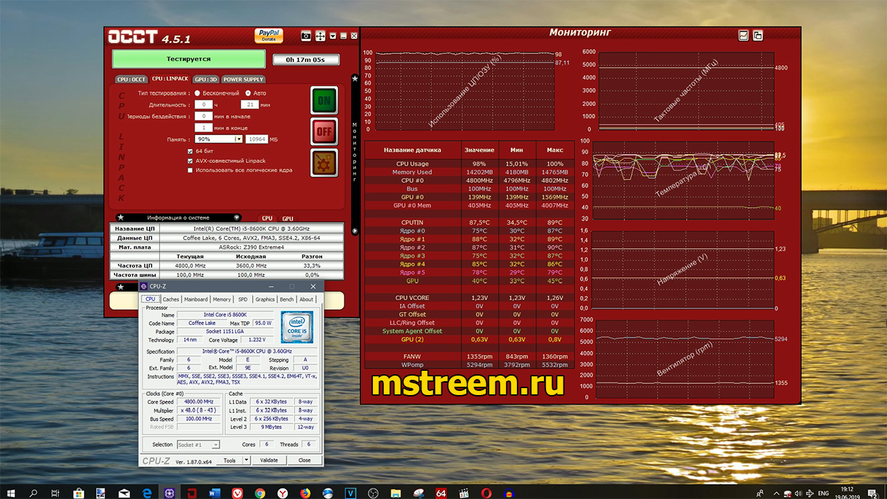
Для прожарки процессора и материнской платы я буду использовать программу OCCT версии 4.5.1 и профиль CPU:Linpack, с включёнными AVX инструкциями.
При этом частота процессора не снижалась при выполнении AVX инструкций, именно так я выставил настройку AVX Ratio Offset.
Сам тест длился 20 минут и 1 минута отводилась для фиксации минимальных температур.
Процессор охлаждался водяной системой охлаждения Arctic Freezer 240
Полная конфигурация тестового компьютера перед вами:
Процессор: Intel Core i5 8600K.
Кулер процессора: Arctic Freezer 240
Материнская плата: ASRock Z390 Extreme 4.
Оперативная память: GoodRam Iridium DDR4 2400 МГц, в разгоне до 2900 МГц (2×8 Гб IR-2400D464L15S/8G).
Видеокарта: Asus Dual GTX 1060 6 Гб (DUAL-GTX1060-O6G).
Накопители: Sata-3 SSD Plextor M5S и Sata-3 HDD Seagate 1 Тб (ST1000DM003).
Корпус: Fractal Design Define R5.
Блок питания: Aerocool Strike-X 800 Ватт.
В операционной системе напряжение процессора при максимальной нагрузке находилось на уровне 1.248-1.232 Вольта, при выставленным в UEFI 1.280 Вольта + «Уровень калибровки 2».
При выставленной калибровке на «Уровень 1» разница в напряжениях будет минимальной.
Разгон Intel Core i5 8600K 4.8 ГГц на материнской плате ASRock Z390 Extreme 4
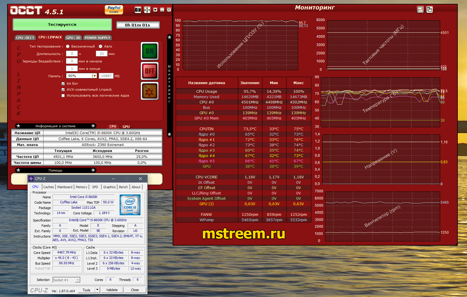
Вот вам наглядный пример:
В BIOS я выставил Vcore на 1.200V и при «Первом» уровне калибровке цепей питания, напряжение в Windows будет отличаться всего на 6 Милливольт, от выставленного в Bios.
Калибровка цепей питания процессора на материнской плате ASRock Z390 Extreme 4
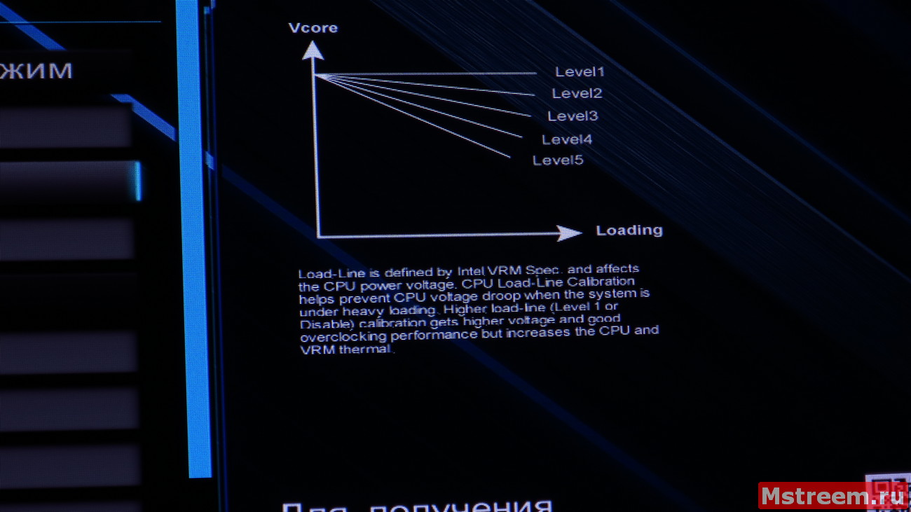
Логика работы калибровки напряжения процессора на материнской плате ASRock Z390 Extreme 4
Питание к центральном процессору подводилось по одному коннектору 8-пин ATX12V.
Второй коннектор на 4-пин я не стал подключать, а вот в случае использования 8-и ядерника я бы его рекомендовал задействовать.
За двадцатиминутный тест, максимальная температура процессора достигала 90-92 градусов по самому горячему ядру. Выше температура уже не росла и быстро стабилизировалась.
На самом деле можно было поэкспериментировать и добиться меньшего питающего напряжения на ядрах процессора при частоте 4.8 ГГц, что конечно же скинет температуры.
Однако я решил максимально нагрузить подсистему питания центрального процессора, чтобы замерить температуру.
Температуру я буду измерять при помощи термопары мультиметра S-Line DT9208.
В обычном состоянии, при включении и замере температуры в комнате, тестер показывает 25-27 градусов Цельсия.
Далее экспериментально я выбрал самое горячее место на цепях питания материнской платы.
Этим местом оказался второй боковой радиатор, именно там была закреплена термопара, (не на его поверхности, а под ним, в максимальной близости у транзисторов и катушек).
Максимальная температура за 20 минут теста составляла диапазон 75-82 градуса Цельсия, а температура в простое около 50 градусов Цельсия.
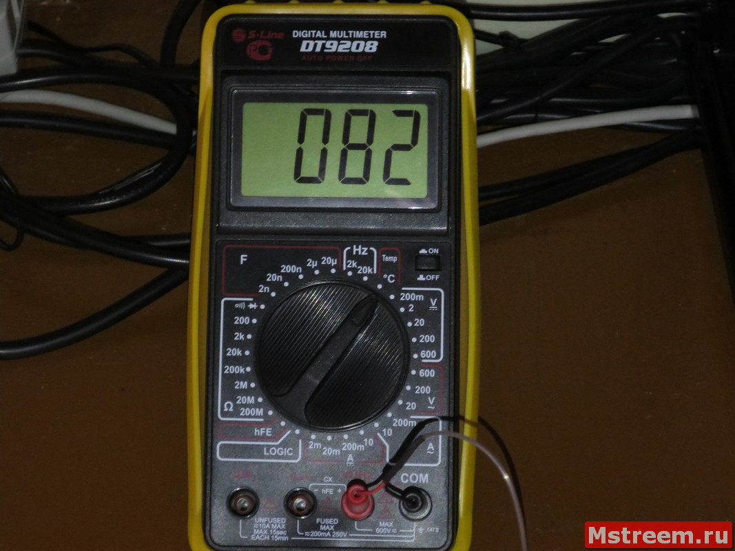
Температура цепей питания процессора (VRM) на материнской плате ASRock Z390 Extreme 4
Напомню, что для охлаждения центрального процессора использовалась водяная система охлаждения, а это значит, что радиаторы дополнительно не обдувались вентиляторами.
Современные цепи питания рассчитаны на температуры около 100-110 градусов Цельсия.
Из всего этого можно сделать вывод, что цепи питания на материнской плате ASRock Z390 Extreme 4 имеют довольно хороший запас прочности.
<Выводы и Заключение:
Материнская плата ASRock Z390 Extreme 4 обладает довольно сбалансированными характеристиками.
Здесь есть и возможность опциональной работы с беспроводными интерфейсами, и пара скоростных портов USB 3.1 Gen 2 (10 Гбит) и возможность использовать два быстрых SSD накопителя M.2.
Хотелось бы побольше USB портов на задней панели, но можно воспользоваться теме же USB хабами, используя быстрые USB 3.1 Gen 2, одни из которых имеет коннектор USB Type C.
Дополнительные разъёмы светодиодных лент, в том числе для работы с адресной RGB светодиодной лентой позволит украсить вашу систему, расположенную в корпусе с прозрачным боковым окном.
Кроме того, подсистема питания позволяет эффективно разгонять шестиядерные процессоры
Также я думаю, что запас эффективности VRM позволит работать и с топовым 9900K на стоковых частотах, уж точно.
За совокупность характеристик и потребительских свойств материнская плата ASRock Z390 Extreme 4 получает заслуженную награду от сайта http://mstreem.ru

Также не забывайте вступать в группу Вконтакте и подписываться на YouTube канал.
YouTube канал Обзоры гаджетов
Вконтакте: Обзоры компьютерного железа, программ и гаджетов
Facebook: Гаджеты, технологии, IT
Удачи Вам,
И до встречи в следующих публикациях и роликах. Пока пока:)
![]() Загрузка…
Загрузка…
![]()
Version 1.1
Published August 2018
Copyright©2018 ASRock INC. All rights reserved.
Copyright Notice:
No part of this documentation may be reproduced, transcribed, transmitted, or translated in any language, in any form or by any means, except duplication of documentation by the purchaser for backup purpose, without written consent of ASRock Inc.
Products and corporate names appearing in this documentation may or may not be registered trademarks or copyrights of their respective companies, and are used only for identification or explanation and to the owners’ benefit, without intent to
infringe.
Disclaimer:
Specifications and information contained in this documentation are furnished for informational use only and subject to change without notice, and should not be constructed as a commitment by ASRock. ASRock assumes no responsibility for any errors or omissions that may appear in this documentation.
With respect to the contents of this documentation, ASRock does not provide warranty of any kind, either expressed or implied, including but not limited to the implied warranties or conditions of merchantability or fitness for a particular purpose.
In no event shall ASRock, its directors, officers, employees, or agents be liable for any indirect, special, incidental, or consequential damages (including damages for loss of profits, loss of business, loss of data, interruption of business and the like), even if ASRock has been advised of the possibility of such damages arising from any defect or error in the documentation or product.
This device complies with Part 15 of the FCC Rules. Operation is subject to the following two conditions:
(1)this device may not cause harmful interference, and
(2)this device must accept any interference received, including interference that may cause undesired operation.
CALIFORNIA, USA ONLY
The Lithium battery adopted on this motherboard contains Perchlorate, a toxic substance controlled in Perchlorate Best Management Practices (BMP) regulations passed by the California Legislature. When you discard the Lithium battery in California, USA, please follow the related regulations in advance.
“Perchlorate Material-special handling may apply, see www.dtsc.ca.gov/hazardouswaste/ perchlorate”
ASRock Website: http://www.asrock.com

AUSTRALIA ONLY
Our goods come with guarantees that cannot be excluded under the Australian Consumer Law. You are entitled to a replacement or refund for a major failure and compensation for any other reasonably foreseeable loss or damage caused by our goods. You are also entitled to have the goods repaired or replaced if the goods fail to be of acceptable quality and the failure does not amount to a major failure. If you require assistance please call ASRock Tel : +886-2-28965588 ext.123 (Standard International call charges apply)
The terms HDMI® and HDMI High-Definition Multimedia Interface, and the HDMI logo are trademarks or registered trademarks of HDMI Licensing LLC in the United States and other countries.
Manufactured under license under U.S. Patent Nos: 5,956,674; 5,974,380; 6,487,535; 7,003,467 & other U.S. and worldwide patents issued & pending. DTS, the Symbol, & DTS and the Symbol together is a registered trademark & DTS Connect, DTS Interactive, DTS Neo:PC are trademarks of DTS, Inc. Product includes software.
© DTS, Inc., All Rights Reserved.
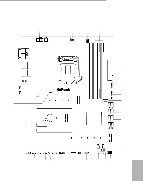
Z390 Extreme4
Motherboard Layout
|
USB: USB1T: US3 2 . BGen1 |
/Mous Keyboard PS2 e |
|||
|
DISPLAY 1 |
||||
|
HDMI1 |
USB 3.1 Gen1
T: USB3
B: USB4
USB 3.1 Gen2
T: USB31_TA_1 Top:
B: USB31_TC_1 RJ-45
|
SPDI Optical Bottom: F |
REARSPK |
Center: |
Central/Bass |
Top: |
|
MI Bottom: CIN |
FRONT |
Center: |
LINE IN |
Top: |
30
LAN
29
Purity
SoundTM 4
ATX12V1 ATX12V2
CPU_FAN2/WP
|
DDR4 A1(64bit,288-pinmodule) |
DDR4 A2(64bit,288-pinmodule) |
DDR4 B1(64bit,288-pinmodule) |
|||||
|
Z390 EXTREME4 |
Ultra M.2 |
||||||
|
CHA_FAN1/WP |
PCIe Gen3 x4 |
||||||
|
LAN |
|||||||
|
PCIE1 |
CT4 |
CT3 |
CT2 |
CT1 |
M2 1 |
||
|
RoHS |
|||||||
|
PCIE2 |
|||||||
|
CMOS |
3 |
Intel |
|||||
|
CLRMOS1 |
Battery |
CT1 |
M2 |
Z390 |
|||
|
1 |
PCIE3
PCIE4
|
(64bit,288-pinmodule) |
ATXPWR1 |
|
DDR4 B2 |
|
|
USB3 5 6 |
|
|
1 |
|
|
USB3 7 8 |
|
|
USB31_TC_2 |
1 |
|
SATA3 4 5 |
|
|
SATA3 2 3 |
|
|
SATA3 0 1 |
|
|
SATA3 A1 A2 |
1
|
PCIE5 |
CT5 |
CT4 |
CT3 |
CT2 |
CT1 |
|
|
BIOS_B_LED1 BIOS_A_LED1 |
||||||
|
PCIE6 |
Ultra M.2 |
BIOS_B1 |
BIOS_A1 |
|||
|
BIOS |
BIOS |
|||||
|
PCIe Gen3 x4 |
PM_OC
|
CHA_FAN2/WP |
TPMS1 |
1 |
COM1 |
USB_1_2 |
USB_3_4 |
SPK_PLED1 |
PLED PWRBTN |
||||||||||||||||||||||||
|
HD_AUDIO1 |
T B1 |
||||||||||||||||||||||||||||||
|
ADDR_LED1 |
RGB_LED1 |
RGB_LED2 1 |
1 |
1 |
|||||||||||||||||||||||||||
|
1 |
1 |
1 |
1 |
1 |
1 |
||||||||||||||||||||||||||
|
HDLED RESET |
PANEL1
|
28 |
27 |
26 |
25 |
24 |
23 |
22 |
21 |
20 |
19 |
18 |
17 |
16 |
7
8
9
10
11
12
13
14
15
English
1

No. Description
18 pin 12V Power Connector (ATX12V1)
24 pin 12V Power Connector (ATX12V2)
3CPU Fan Connector (CPU_FAN1)
4CPU/Water Pump Fan Connector (CPU_FAN2/WP)
52 x 288-pin DDR4 DIMM Slots (DDR4_A1, DDR4_B1)
62 x 288-pin DDR4 DIMM Slots (DDR4_A2, DDR4_B2)
7ATX Power Connector (ATXPWR1)
8USB 3.1 Gen1 Header (USB3_5_6)
9USB 3.1 Gen1 Header (USB3_7_8)
10Front Panel Type C USB 3.1 Gen1 Header (USB31_TC_2)
11SATA3 Connectors (SATA3_4_5)
12SATA3 Connectors (SATA3_2_3)
13SATA3 Connectors (SATA3_0_1)
14SATA3 Connectors (SATA3_A1_A2)
15Performance Mode / Easy OC Header (PM_OC)
16Chassis/Water Pump Fan Connector (CHA_FAN3/WP)
17System Panel Header (PANEL1)
18Power LED and Speaker Header (SPK_PLED1)
19USB 2.0 Header (USB_3_4)
20USB 2.0 Header (USB_1_2)
21COM Port Header (COM1)
22TPM Header (TPMS1)
23Chassis/Water Pump Fan Connector (CHA_FAN2/WP)
24Thunderbolt AIC Connector (TB1)
25RGB LED Header (RGB_LED2)
26RGB LED Header (RGB_LED1)
27Addressable LED Header (ADDR_LED1)
28Front Panel Audio Header (HD_AUDIO1)
29Clear CMOS Jumper (CLRMOS1)
30Chassis/Water Pump Fan Connector (CHA_FAN1/WP)
English
2
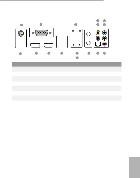
Z390 Extreme4
I/O Panel
|
4 |
6 |
||||||||||||||||||||
|
1 |
2 |
3 |
5 |
7 |
|||||||||||||||||
|
16 |
15 |
14 |
13 |
11 |
10 |
9 |
8 |
||
|
12 |
|||||||||
|
No. |
Description |
No. |
Description |
||||||
|
1 |
PS/2 Mouse/Keyboard Port |
9 |
Optical SPDIF Out Port |
||||||
|
2 |
D-Sub Port |
10 |
Antenna Ports |
||||||
|
3 |
LAN RJ-45 Port* |
11 |
USB 3.1 Gen2 Type-A Port (USB31_TA_1) |
||||||
|
4 |
Central / Bass (Orange) |
12 |
USB 3.1 Gen2 Type-C Port (USB31_TC_1) |
||||||
|
5 |
Rear Speaker (Black) |
13 |
USB 3.1 Gen1 Ports (USB3_34) |
||||||
|
6 |
Line In (Light Blue) |
14 |
HDMI Port |
||||||
|
7 |
Front Speaker (Lime)** |
15 |
DisplayPort 1.2 |
||||||
|
8 |
Microphone (Pink) |
16 |
USB 3.1 Gen1 Port (USB3_12) |
||||||
English
3
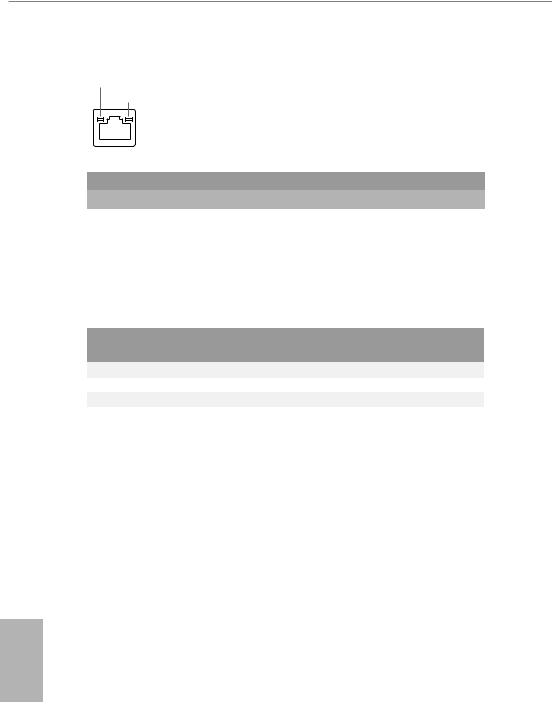
*There are two LEDs on each LAN port. Please refer to the table below for the LAN port LED indications.
ACT/LINK LED SPEED LED
|
LAN Port |
||||||
|
Activity / Link LED |
Speed LED |
|||||
|
Status |
Description |
Status |
Description |
|||
|
Off |
No Link |
Off |
10Mbps connection |
|||
|
Blinking |
Data Activity |
Orange |
100Mbps connection |
|||
|
On |
Link |
Green |
1Gbps connection |
|||
** If you use a 2-channel speaker, please connect the speaker’s plug into “Front Speaker Jack”. See the table below for connection details in accordance with the type of speaker you use.
|
Audio Output |
Front Speaker |
Rear Speaker |
Central / Bass |
Line In |
|
Channels |
(No.7) |
(No. 5) |
(No. 4) |
(No. 6) |
|
2 |
V |
— |
— |
— |
|
4 |
V |
V |
— |
— |
|
6 |
V |
V |
V |
— |
|
8 |
V |
V |
V |
V |
English
4
Z390 Extreme4
Chapter 1 Introduction
Thank you for purchasing ASRock Z390 Extreme4 motherboard, a reliable motherboard produced under ASRock’s consistently stringent quality control. It delivers excellent performance with robust design conforming to ASRock’s commitment to quality and endurance.
Because the motherboard specifications and the BIOS software might be updated, the content of this documentation will be subject to change without notice. In case any modifications of this documentation occur, the updated version will be available on ASRock’s website without further notice. If you require technical support related to this motherboard, please visit our website for specific information about the model you are using. You may find the latest VGA cards and CPU support list on ASRock’s website as well. ASRock website http://www.asrock.com.
1.1 Package Contents
•ASRock Z390 Extreme4 Motherboard (ATX Form Factor)
•ASRock Z390 Extreme4 Quick Installation Guide
•ASRock Z390 Extreme4 Support CD
•1 x I/O Panel Shield
•4 x Serial ATA (SATA) Data Cables (Optional)
•1 x ASRock SLI_HB_Bridge_2S Card (Optional)
•3 x Screws for M.2 Socket (Optional)
English
5

English
1.2 Specifications
|
Platform |
• |
ATX Form Factor |
|
CPU |
• |
Supports 9th and 8th Gen Intel® CoreTM Processors (Socket |
|
1151) |
||
|
• |
Digi Power design |
|
|
• 12 Power Phase design |
||
|
• Supports Intel® Turbo Boost 2.0 Technology |
||
|
• Supports Intel® K-Series unlocked CPUs |
||
|
• Supports ASRock BCLK Full-range Overclocking |
||
|
Chipset |
• |
Intel® Z390 |
|
Memory |
• |
Dual Channel DDR4 Memory Technology |
•4 x DDR4 DIMM Slots
•Supports DDR4 4300+(OC)*/4266(OC)/4133(OC)/4000 (OC)/3866(OC)/3800(OC)/3733(OC)/3600(OC)/3200(OC)/ 2933(OC)/2800(OC)/2666/2400/2133 non-ECC, un-buffered memory
*Please refer to Memory Support List on ASRock’s website for more information. (http://www.asrock.com/)
•Supports ECC UDIMM memory modules (operate in nonECC mode)
•Max. capacity of system memory: 64GB
•Supports Intel® Extreme Memory Profile (XMP) 2.0
•15μ Gold Contact in DIMM Slots
|
Expansion |
• 3 x PCI Express 3.0 x16 Slots (PCIE2/PCIE4/PCIE6: single |
|
Slot |
at x16 (PCIE2); dual at x8 (PCIE2) / x8 (PCIE4); triple at x8 |
|
(PCIE2) / x8 (PCIE4) / x4 (PCIE6))* |
|
|
* Supports NVMe SSD as boot disks |
|
|
• 3 x PCI Express 3.0 x1 Slots (Flexible PCIe) |
|
|
• Supports AMD Quad CrossFireXTM, 3-Way CrossFireXTM |
|
|
and CrossFireXTM |
|
|
• Supports NVIDIA® Quad SLITM and SLITM |
|
|
• 1 x M.2 Socket (Key E), supports type 2230 WiFi/BT module |
|
|
and Intel® CNVi (Integrated WiFi/BT) |
|
|
• 15μ Gold Contact in VGA PCIe Slot (PCIE2) |
6

Z390 Extreme4
|
Graphics |
• |
Intel® UHD Graphics Built-in Visuals and the VGA outputs |
|
can be supported only with processors which are GPU |
||
|
integrated. |
||
|
• Supports Intel® UHD Graphics Built-in Visuals : Intel® |
||
|
Quick Sync Video with AVC, MVC (S3D) and MPEG-2 Full |
||
|
HW Encode1, Intel® InTruTM 3D, Intel® Clear Video HD |
||
|
Technology, Intel® InsiderTM, Intel® UHD Graphics |
||
|
• |
DirectX 12 |
|
|
• HWAEncode/Decode: AVC/H.264, HEVC/H.265 8-bit, |
||
|
HEVC/H.265 10-bit, VP8, VP9 8-bit, VP9 10-bit (Decode |
||
|
only), MPEG2, MJPEG, VC-1 (Decode only) |
||
|
• Three graphics output options: D-Sub, HDMI and |
||
|
DisplayPort 1.2 |
||
|
• |
Supports Triple Monitor |
|
|
• Supports HDMI with max. resolution up to 4K x 2K |
||
|
(4096×2160) @ 30Hz |
||
|
• Supports DisplayPort 1.2 with max. resolution up to 4K x 2K |
||
|
(4096×2304) @ 60Hz |
||
|
• Supports D-Sub with max. resolution up to 1920×1200 @ |
||
|
60Hz |
||
|
• Supports Auto Lip Sync, Deep Color (12bpc), xvYCC and |
||
|
HBR (High Bit Rate Audio) with HDMI Port (Compliant |
||
|
HDMI monitor is required) |
||
|
• Supports HDCP with HDMI and DisplayPort 1.2 Ports |
||
|
• Supports 4K Ultra HD (UHD) playback with HDMI and |
||
|
DisplayPort 1.2 Ports |
||
|
Audio |
• |
7.1 CH HD Audio with Content Protection (Realtek |
|
ALC1220 Audio Codec) |
||
|
• Premium Blu-ray Audio support |
||
|
• |
Supports Surge Protection |
|
|
• Supports Purity SoundTM 4 |
||
|
— Nichicon Fine Gold Series Audio Caps |
||
|
— 120dB SNR DAC with Differential Amplifier |
||
|
— NE5532 Premium Headset Amplifier for Front Panel |
||
|
Audio Connector (Supports up to 600 Ohm headsets) |
||
|
— Pure Power-In |
English
7

English
|
— Direct Drive Technology |
||
|
— PCB Isolate Shielding |
||
|
— Impedance Sensing on Rear Out port |
||
|
— Individual PCB Layers for R/L Audio Channel |
||
|
— RGB LED |
||
|
— 15μ Gold Audio Connector |
||
|
• |
Supports DTS Connect |
|
|
LAN |
• |
Gigabit LAN 10/100/1000 Mb/s |
|
• Giga PHY Intel® I219V |
||
|
• Supports Wake-On-LAN |
||
|
• |
Supports Lightning/ESD Protection |
|
|
• Supports Energy Efficient Ethernet 802.3az |
||
|
• |
Supports PXE |
|
|
Rear Panel |
• |
2 x Antenna Ports |
|
I/O |
• |
1 x PS/2 Mouse/Keyboard Port |
|
• 1 x D-Sub Port |
||
|
• 1 x HDMI Port |
||
|
• 1 x DisplayPort 1.2 |
||
|
• 1 x Optical SPDIF Out Port |
||
|
• 1 x USB 3.1 Gen2 Type-A Port (10 Gb/s) (ReDriver) (Supports |
||
|
ESD Protection) |
||
|
• 1 x USB 3.1 Gen2 Type-C Port (10 Gb/s) (ReDriver) (Supports |
||
|
ESD Protection) |
||
|
• 4 x USB 3.1 Gen1 Ports (Intel® Z390) (Supports ESD |
||
|
Protection) |
||
|
• 1 x RJ-45 LAN Port with LED (ACT/LINK LED and SPEED |
||
|
LED) |
||
|
• HD Audio Jacks: Rear Speaker / Central / Bass / Line in / |
||
|
Front Speaker / Microphone |
||
|
Storage |
• |
6 x SATA3 6.0 Gb/s Connectors, support RAID (RAID 0, |
|
RAID 1, RAID 5, RAID 10, Intel Rapid Storage Technology |
||
|
16), NCQ, AHCI and Hot Plug* |
• 2 x SATA3 6.0 Gb/s Connectors by ASMedia ASM1061, support NCQ, AHCI and Hot Plug
8
![]()
Z390 Extreme4
*M2_1, SATA3_0 and SATA3_1 share lanes. If either one of them is in use, the others will be disabled.
*M2_2, SATA3_4 and SATA3_5 share lanes. If either one of them is in use, the others will be disabled.
•1 x Ultra M.2 Socket (M2_1), supports M Key type 2230/2242/2260/2280 M.2 SATA3 6.0 Gb/s module and M.2 PCI Express module up to Gen3 x4 (32 Gb/s)**
•1 x Ultra M.2 Socket (M2_2), supports M Key type 2230/2242/2260/2280/22110 M.2 SATA3 6.0 Gb/s module and M.2 PCI Express module up to Gen3 x4 (32 Gb/s)**
**Supports Intel® OptaneTM Technology
**Supports NVMe SSD as boot disks
**Supports ASRock U.2 Kit
|
Connector |
• 1 x COM Port Header |
•1 x TPM Header
•1 x Power LED and Speaker Header
•2 x RGB LED Headers
*Support in total up to 12V/3A, 36W LED Strip
•1 x Addressable LED Header
*Supports in total up to 5V/3A, 15W LED Strip
•1 x CPU Fan Connector (4-pin)
*The CPU Fan Connector supports the CPU fan of maximum 1A (12W) fan power.
•1 x CPU/Water Pump Fan Connector (4-pin) (Smart Fan Speed Control)
*The CPU/Water Pump Fan supports the water cooler fan of maximum 2A (24W) fan power.
•3 x Chassis/Water Pump Fan Connectors (4-pin) (Smart Fan Speed Control)
*The Chassis/Water Pump Fan supports the water cooler fan of maximum 2A (24W) fan power.
*CPU_FAN2/WP, CHA_FAN1/WP, CHA_FAN2/WP and CHA_FAN3/WP can auto detect if 3-pin or 4-pin fan is in use.
•1 x 24 pin ATX Power Connector (Hi-Density Power Connector)
•1 x 8 pin 12V Power Connector (Hi-Density Power Connector)
English
9

English
• 1 x 4 pin 12V Power Connector (Hi-Density Power Connector)
• 1 x Front Panel Audio Connector (15μ Gold Audio Connector)
• 1 x Thunderbolt AIC Connector (5-pin)
• 2 x USB 2.0 Headers (Support 4 USB 2.0 ports) (Intel® Z390) (Supports ESD Protection)
• 2 x USB 3.1 Gen1 Headers (Support 4 USB 3.1 Gen1 ports)
|
(ASMedia ASM1074 hub) (Supports ESD Protection) |
||
|
• 1 x Front Panel Type C USB 3.1 Gen1 Header (Intel® Z390) |
||
|
(Supports ESD Protection) |
||
|
• 1 x Performance Mode / Easy OC Header |
||
|
BIOS |
• |
2 x AMI UEFI Legal BIOS with multilingual GUI support (1 |
|
Feature |
x Main BIOS and 1 x Backup BIOS) |
|
|
• Supports Secure Backup UEFI Technology |
||
|
• ACPI 6.0 Compliant wake up events |
||
|
• |
SMBIOS 2.7 Support |
|
|
• CPU Core/Cache, GT, DRAM, PCH 1.0V, VCCIO, VCCST, |
||
|
VCCSA, VCCPLL, CPU Internal PLL, GT PLL, Ring PLL, |
||
|
System Agent PLL, Memory Controller PLL Voltage Multi- |
||
|
adjustment |
||
|
Hardware |
• |
Temperature Sensing: CPU, CPU/Water Pump, Chassis/Wa- |
|
Monitor |
ter Pump Fans |
|
|
• Fan Tachometer: CPU, CPU/Water Pump, Chassis/Water |
||
|
Pump Fans |
||
|
• Quiet Fan (Auto adjust chassis fan speed by CPU tempera- |
||
|
ture): CPU, CPU/Water Pump, Chassis/Water Pump Fans |
||
|
• Fan Multi-Speed Control: CPU, CPU/Water Pump, Chassis/ |
||
|
Water Pump Fans |
||
|
• Voltage monitoring: +12V, +5V, +3.3V, CPU Vcore, DRAM, |
||
|
VPPM, PCH 1.0V, VCCSA, VCCST, VCCIO |
||
|
OS |
• |
Microsoft® Windows® 10 64-bit |
|
Certifica- |
• |
FCC, CE |
|
tions |
• |
ErP/EuP ready (ErP/EuP ready power supply is required) |
10
Z390 Extreme4
* For detailed product information, please visit our website: http://www.asrock.com
Please realize that there is a certain risk involved with overclocking, including adjusting the setting in the BIOS, applying Untied Overclocking Technology, or using third-party overclocking tools. Overclocking may affect your system’s stability, or even cause damage to the components and devices of your system. It should be done at your own risk and expense. We are not responsible for possible damage caused by overclocking.
English
11

Chapter 2 Installation
This is an ATX form factor motherboard. Before you install the motherboard, study the configuration of your chassis to ensure that the motherboard fits into it.
Pre-installation Precautions
Take note of the following precautions before you install motherboard components or change any motherboard settings.
•Make sure to unplug the power cord before installing or removing the motherboard components. Failure to do so may cause physical injuries and damages to motherboard components.
•In order to avoid damage from static electricity to the motherboard’s components, NEVER place your motherboard directly on a carpet. Also remember to use a grounded wrist strap or touch a safety grounded object before you handle the components.
•Hold components by the edges and do not touch the ICs.
•Whenever you uninstall any components, place them on a grounded anti-static pad or in the bag that comes with the components.
•When placing screws to secure the motherboard to the chassis, please do not overtighten the screws! Doing so may damage the motherboard.
English
12
Z390 Extreme4
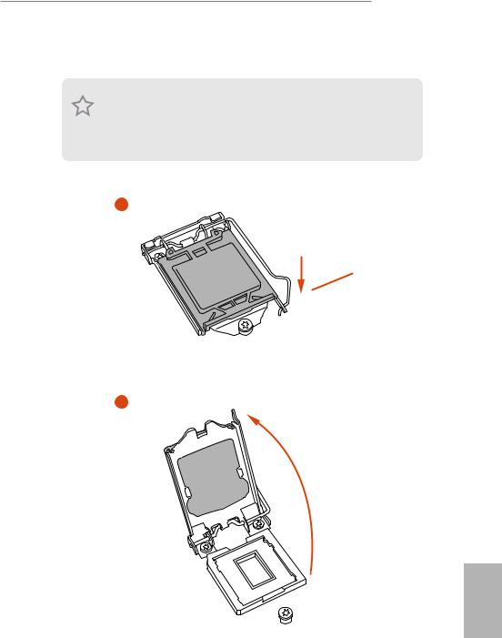
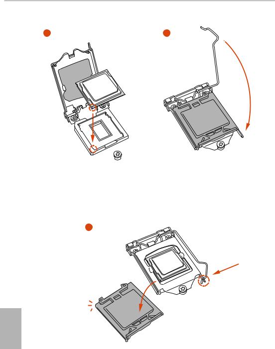
2.1Installing the CPU
1.Before you insert the 1151-Pin CPU into the socket, please check if the PnP cap is on the socket, if the CPU surface is unclean, or if there are any bent pins in the socket. Do not force to insert the CPU into the socket if above situation is found. Otherwise, the CPU will be seriously damaged.
2.Unplug all power cables before installing the CPU.
1
A
 B
B
2
English
13
14

Z390 Extreme4
Please save and replace the cover if the processor is removed. The cover must be placed if you wish to return the motherboard for after service.
English
15

2.2 Installing the CPU Fan and Heatsink
N _FA PU C
English
16
Z390 Extreme4
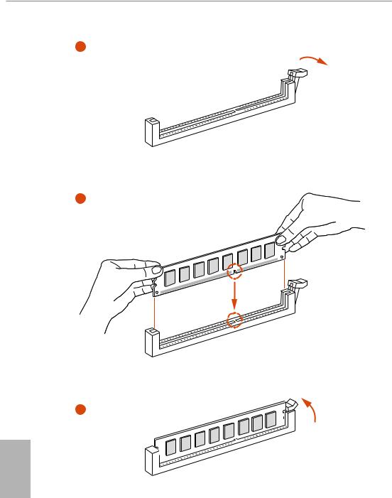
2.3 Installing Memory Modules (DIMM)
This motherboard provides four 288-pin DDR4 (Double Data Rate 4) DIMM slots, and supports Dual Channel Memory Technology.
1.For dual channel configuration, you always need to install identical (the same brand, speed, size and chip-type) DDR4 DIMM pairs.
2.It is unable to activate Dual Channel Memory Technology with only one or three memory module installed.
3.It is not allowed to install a DDR, DDR2 or DDR3 memory module into a DDR4 slot; otherwise, this motherboard and DIMM may be damaged.
Dual Channel Memory Configuration
|
Priority |
DDR4_A1 |
DDR4_A2 |
DDR4_B1 |
DDR4_B2 |
|
1 |
Populated |
Populated |
||
|
2 |
Populated |
Populated |
Populated |
Populated |
The DIMM only fits in one correct orientation. It will cause permanent damage to the motherboard and the DIMM if you force the DIMM into the slot at incorrect orientation.
English
17
18
![]()
Z390 Extreme4
2.4 Expansion Slots (PCI Express Slots)
There are 6 PCI Express slots on the motherboard.
Before installing an expansion card, please make sure that the power supply is switched off or the power cord is unplugged. Please read the documentation of the expansion card and make necessary hardware settings for the card before you start the installation.
PCIe slots:
PCIE1 (PCIe 3.0 x1 slot) is used for PCI Express x1 lane width cards.
PCIE2 (PCIe 3.0 x16 slot) is used for PCI Express x16 lane width graphics cards. PCIE3 (PCIe 3.0 x1 slot) is used for PCI Express x1 lane width cards.
PCIE4 (PCIe 3.0 x16 slot) is used for PCI Express x8 lane width graphics cards. PCIE5 (PCIe 3.0 x1 slot) is used for PCI Express x1 lane width cards.
PCIE6 (PCIe 3.0 x16 slot) is used for PCI Express x4 lane width graphics cards.
PCIe Slot Configurations
|
PCIE2 |
PCIE4 |
PCIE6 |
||
|
Single Graphics Card |
x16 |
N/A |
N/A |
|
|
Two Graphics Cards in |
||||
|
CrossFireXTM or SLITM |
x8 |
x8 |
N/A |
|
|
Mode |
||||
|
Three Graphics Cards in |
x8 |
x8 |
x4 |
|
|
3-Way CrossFireXTM Mode |
||||
For a better thermal environment, please connect a chassis fan to the motherboard’s chassis fan connector (CHA_FAN1/WP, CHA_FAN2/WP or CHA_FAN3/WP) when using multiple graphics cards.
English
19
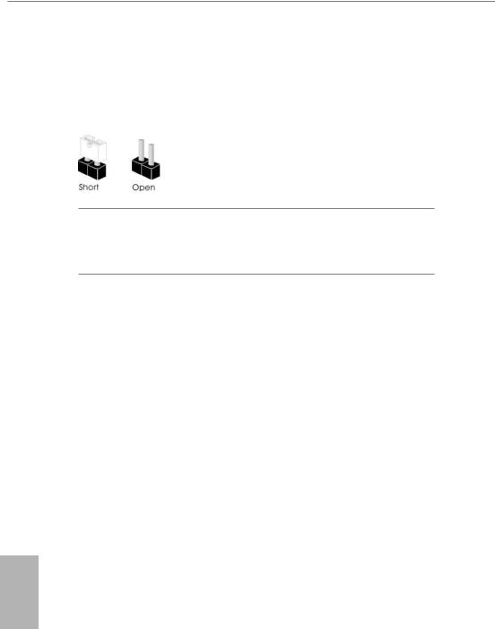
2.5 Jumpers Setup
The illustration shows how jumpers are setup. When the jumper cap is placed on the pins, the jumper is “Short”. If no jumper cap is placed on the pins, the jumper is “Open”.
|
Clear CMOS Jumper |
Short: Clear CMOS |
|
|
(CLRCMOS1) |
2-pin Jumper |
Open: Default |
|
(see p.1, No. 29) |
||
CLRCMOS1 allows you to clear the data in CMOS. The data in CMOS includes system setup information such as system password, date, time, and system setup parameters. To clear and reset the system parameters to default setup, please turn off the computer and unplug the power cord, then use a jumper cap to short the pins on CLRCMOS1 for 3 seconds. Please remember to remove the jumper cap after clearing the CMOS. If you need to clear the CMOS when you just finish updating the BIOS, you must boot up the system first, and then shut it down before you do the clear-CMOS action.
English
20
Z390 Extreme4
2.6 Onboard Headers and Connectors
Onboard headers and connectors are NOT jumpers. Do NOT place jumper caps over these headers and connectors. Placing jumper caps over the headers and connectors will cause permanent damage to the motherboard.
System Panel Header
(9-pin PANEL1)
(see p.1, No. 17)
PLED+ PLED-
PWRBTN#
GND
1
GND RESET#
GND HDLED-
HDLED+
Connect the power button, reset button and system status indicator on the chassis to this header according to the pin assignments below. Note the positive and negative pins before connecting the cables.
PWRBTN (Power Button):
Connect to the power button on the chassis front panel. You may configure the way to turn off your system using the power button.
RESET (Reset Button):
Connect to the reset button on the chassis front panel. Press the reset button to restart the computer if the computer freezes and fails to perform a normal restart.
PLED (System Power LED):
Connect to the power status indicator on the chassis front panel. The LED is on when the system is operating. The LED keeps blinking when the system is in S1/S3 sleep state. The LED is off when the system is in S4 sleep state or powered off (S5).
HDLED (Hard Drive Activity LED):
Connect to the hard drive activity LED on the chassis front panel. The LED is on when the hard drive is reading or writing data.
The front panel design may differ by chassis. A front panel module mainly consists of power button, reset button, power LED, hard drive activity LED, speaker and etc. When connecting your chassis front panel module to this header, make sure the wire assignments and the pin assignments are matched correctly.
English
21
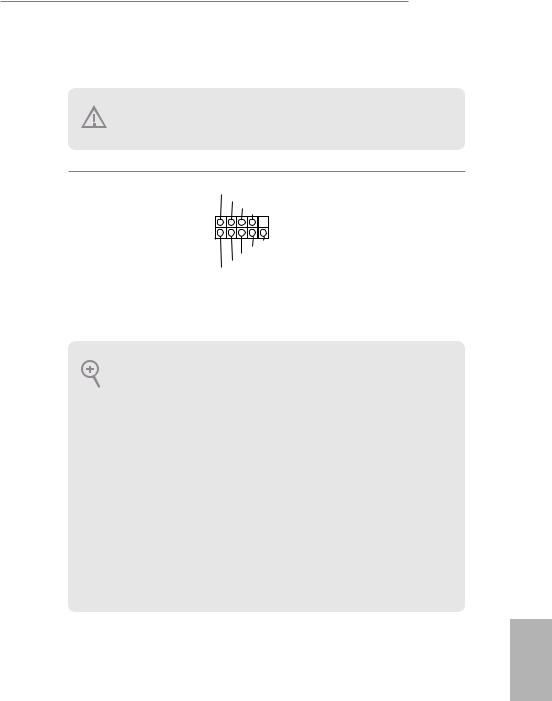
Power LED and Speaker
Header
(7-pin SPK_PLED1)
(see p.1, No. 18)
SPEAKER
DUMMY DUMMY +5V
1
PLED+
PLED+ PLED-
Please connect the chassis power LED and the chassis speaker to this header.
Serial ATA3 Connectors (SATA3_4_5:
see p.1, No. 11) (SATA3_2_3: see p.1, No. 12) (SATA3_0_1: see p.1, No. 13) (SATA3_A1_A2: see p.1, No. 14)
USB 2.0 Headers
(9-pin USB_1_2)
(see p.1, No. 20)
(9-pin USB_3_4)
(see p.1, No. 19)
English
|
4 |
5 |
These eight SATA3 |
|
|
_ |
_ |
connectors support SATA |
|
|
SATA3 |
SATA3 |
||
|
data cables for internal |
|||
|
storage devices with up to |
|||
|
2 |
3 |
6.0 Gb/s data transfer rate. |
|
|
SATA3 |
SATA3 |
* M2_1, SATA3_0 and |
|
|
SATA3_1 share lanes. If |
|||
|
either one of them is in |
|||
|
0 |
1 |
use, the others will be |
|
|
SATA3 |
SATA3 |
disabled. |
|
|
* M2_2, SATA3_4 and |
|||
|
A1 |
A2 |
SATA3_5 share lanes. If |
|
|
either one of them is in |
|||
|
SATA3 |
SATA3 |
use, the others will be |
|
|
disabled. |
|||
|
*To minimize the boot |
|||
|
time, use Intel® Z390 |
|||
|
SATA ports (SATA3_0) |
|||
|
for your SSDs. |
USB_PWR
P- P+ GND DUMMY
1
GND
USBP_—PWRP+
There are two headers on this motherboard. Each USB 2.0 header can support two ports.
22
Z390 Extreme4
USB 3.1 Gen1 Headers
(19-pin USB3_5_6)
(see p.1, No. 
(19-pin USB3_7_8)
(see p.1, No. 9)
Vbus
IntA_PA_SSRX-
IntA_PA_SSRX+
GND
IntA_PA_SSTX-
IntA_PA_SSTX+
GND
IntA_PA_D-
IntA_PA_D+
Vbus
IntA_PB_SSRX-
IntA_PB_SSRX+
GND
IntA_PB_SSTX-
IntA_PB_SSTX+
GND
IntA_PB_D-
IntA_PB_D+
Dummy
1
There are two headers on this motherboard. Each USB 3.1 Gen1 header can support two ports.
|
Front Panel Type C USB |
There is one Front |
|||||||||||||||||||||||||||||||||||||||||
|
3.1 Gen1 Header |
Panel Type C USB 3.1 |
|||||||||||||||||||||||||||||||||||||||||
|
(26-pin USB31_TC_2) |
Gen1 Header on this |
|||||||||||||||||||||||||||||||||||||||||
|
(see p.1, No. 10) |
motherboard. This header |
|||||||||||||||||||||||||||||||||||||||||
|
is used for connecting a |
||||||||||||||||||||||||||||||||||||||||||
|
USB 3.1 Gen1 module for |
||||||||||||||||||||||||||||||||||||||||||
|
additional USB 3.1 Gen1 |
||||||||||||||||||||||||||||||||||||||||||
|
ports. |
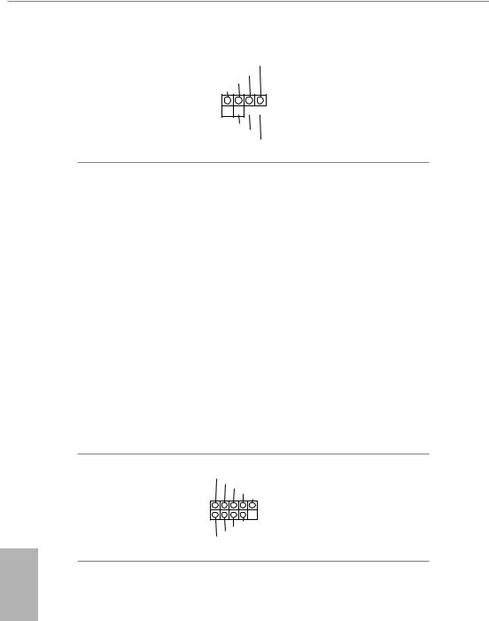
Front Panel Audio Header
(9-pin HD_AUDIO1)
(see p.1, No. 28)
GND PRESENCE#
MIC_RET
OUT_RET
1


OUT2_L J_SENSE
OUT2_R MIC2_R
MIC2_L
This header is for connecting audio devices to the front audio panel.
1.High Definition Audio supports Jack Sensing, but the panel wire on the chassis must support HDA to function correctly. Please follow the instructions in our manual and chassis manual to install your system.
2.If you use an AC’97 audio panel, please install it to the front panel audio header by the steps below:
A.Connect Mic_IN (MIC) to MIC2_L.
B.Connect Audio_R (RIN) to OUT2_R and Audio_L (LIN) to OUT2_L.
C.Connect Ground (GND) to Ground (GND).
D.MIC_RET and OUT_RET are for the HD audio panel only. You don’t need to connect them for the AC’97 audio panel.
E.To activate the front mic, go to the “FrontMic” Tab in the Realtek Control panel and adjust “Recording Volume”.
English
23
English
Chassis/Water Pump Fan
Connectors
(4-pin CHA_FAN1/WP)
(see p.1, No. 30)
(4-pin CHA_FAN2/WP)
(see p.1, No. 23)
GND
FAN_VOLTAGE FAN_SPEED
FAN_SPEED_CONTROL
1 2 3 4
GND
FAN_VOLTAGE FAN_SPEED
FAN_SPEED_CONTROL
1 2 3 4
This motherboard provides three 4-Pin water cooling chassis fan connectors. If you plan to connect a 3-Pin chassis water cooler fan, please connect it to Pin 1-3.
|
(4-pin CHA_FAN3/WP) |
GND |
|||
|
FAN_VOLTAGE |
||||
|
(see p.1, No. 16) |
FAN_SPEED |
|||
|
FAN_SPEED_CONTROL |
||||
|
1 |
2 |
3 |
4 |
|
CPU Fan Connector
(4-pin CPU_FAN1)
(see p.1, No. 3)
FAN_SPEED_CONTROL CPU_FAN_SPEED FAN_VOLTAGE
GND
1 2 3 4
This motherboard provides a 4-Pin CPU fan (Quiet Fan) connector. If you plan to connect a 3-Pin CPU fan, please connect it to Pin 1-3.
CPU/Water Pump Fan
Connector
(4-pin CPU_FAN2/WP)
(see p.1, No. 4)
|
FAN_SPEED_CONTROL |
4 |
|
CPU_FAN_SPEED |
3 |
|
FAN_VOLTAGE |
2 |
|
GND |
1 |
This motherboard provides a 4-Pin water cooling CPU fan connector. If you plan to connect a 3-Pin CPU water cooler fan, please connect it to Pin 1-3.
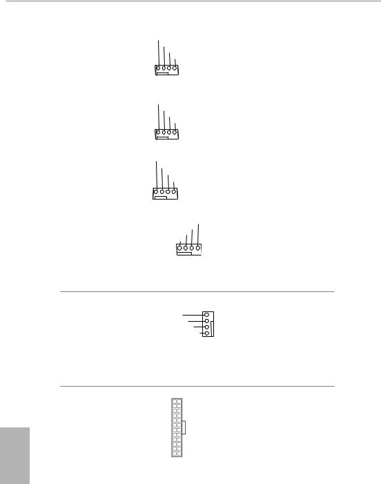
|
ATX Power Connector |
12 |
24 |
This motherboard pro- |
|
(24-pin ATXPWR1) |
vides a 24-pin ATX power |
||
|
(see p.1, No. 7) |
connector. To use a 20-pin |
||
|
ATX power supply, please |
|||
|
plug it along Pin 1 and Pin |
|||
|
1 |
13 |
13. |
24
ATX 12V Power
Connector
(8-pin ATX12V1)
(see p.1, No. 1)
ATX 12V Power
Connector
(4-pin ATX12V2)
(see p.1, No. 2)
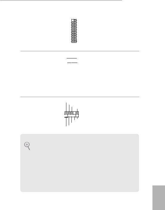
Thunderbolt AIC
Connectors
(5-pin TB1)
(see p.1, No. 24)
Serial Port Header
(9-pin COM1)
(see p.1, No. 21)
TPM Header
(17-pin TPMS1)
(see p.1, No. 22)
RRXD1
DDTR#1
DDSR#1
CCTS#1
1
RRI#1
RRTS#1 GND
TTXD1
DDCD#1
|
GND |
+3VSB |
LAD0 |
+3V |
LAD3 |
PCIRST# |
FRAME |
PCICLK |
|
1 |
|||||||
|
GND |
SERIRQ# S_PWRDWN# |
GND |
LAD1 |
LAD2 |
SMB_DATA_MAIN |
SMB_CLK_MAIN |
DGN |
Z390 Extreme4
This motherboard provides an 8-pin ATX 12V power connector. To use a 4-pin ATX power supply, please plug it along Pin 1 and Pin 5.
Please connect an ATX 12V power supply to this connector.
*The power supply plug fits into this connector in only one orientation.
Please connect a Thunderbolt™ add-in card (AIC) to the Thunderbolt AIC connector via the GPIO cable.
*Please install the Thunderbolt™ AIC card to PCIE6 (default slot).
This COM1 header supports a serial port module.
|
This connector supports Trusted |
||
|
Platform Module (TPM) system, |
||
|
which can securely store keys, |
||
|
digital certificates, passwords, |
||
|
and data. A TPM system also |
||
|
helps enhance network security, |
||
|
protects digital identities, and |
English |
|
|
ensures platform integrity. |
||
25
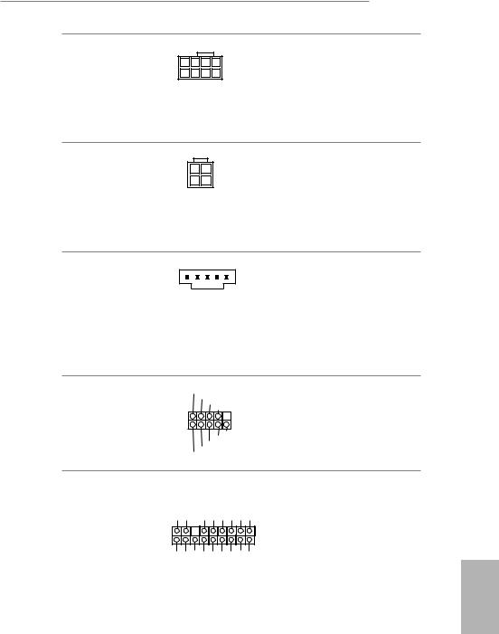
RGB LED Headers
(4-pin RGB_LED1)
(see p.1, No. 26)
(4-pin RGB_LED2)
(see p.1, No. 25)
1 
12V G R B
RGB header is used to connect RGB LED extension cable which allows users to choose from various LED lighting effects.
Caution: Never install the RGB LED cable in the wrong orientation; otherwise, the cable may be damaged.
*Please refer to page 33 for further instructions on this header.
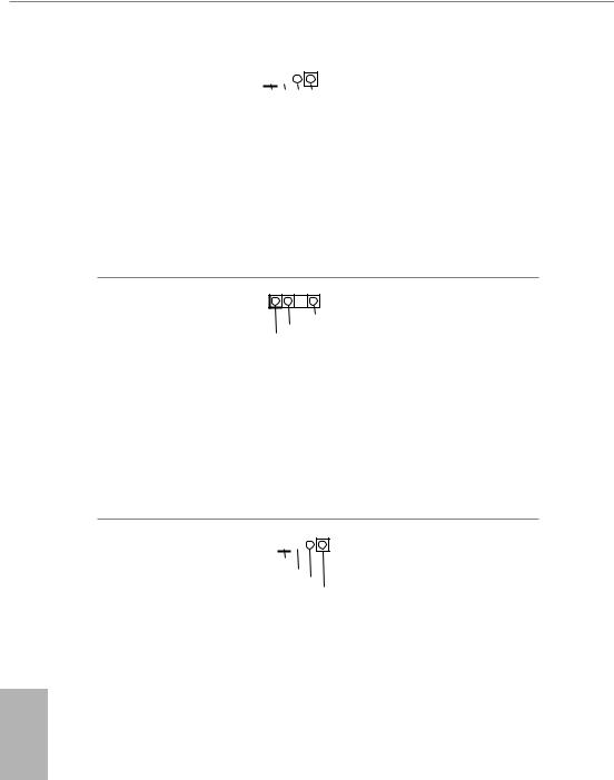
Addressable LED Header
(3-pin ADDR_LED1)
(see p.1, No. 27)
This header is used to connect Addressable LED extension cable which allows users to choose from various LED lighting effects.
Caution: Never install the Addressable LED cable in the wrong orientation; otherwise, the cable may be damaged.
*Please refer to page 34 for further instructions on this header.
Performance Mode / Easy
OC Header
(4-pin PM_OC)
(see p.1, No. 15)
1 
Button+ Button-
OCLED+ OCLED —
Please connect the OC switch and OC LED indicator on the chassis to this header according to the pin assignments. Note the positive and negative pins before connecting the cables.
English
26
Z390 Extreme4
2.7M.2 WiFi/BT Module and Intel® CNVi (Integrated WiFi/BT) Installation Guide
The M.2, also known as the Next Generation Form Factor (NGFF), is a small size and versatile card edge connector that aims to replace mPCIe and mSATA. The M.2 Socket (Key E) supports type 2230 WiFi/BT module and Intel® CNVi (Integrated WiFi/BT).
* The M.2 socket does not support SATA M.2 SSDs.
Before you install Intel® Integrated Connectivity (CNVi) module, be sure to turn off the AC power.
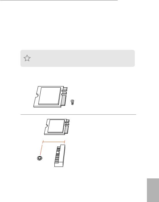
Installing the WiFi/BT module or Intel® CNVi (Integrated WiFi/BT)
Step 1
Prepare a type 2230 WiFi/BT module or Intel® CNVi (Integrated WiFi/BT) and the screw.
Step 2
Find the nut location to be used.
PCB Length: 3cm
Module Type: Type2230
A
English
27
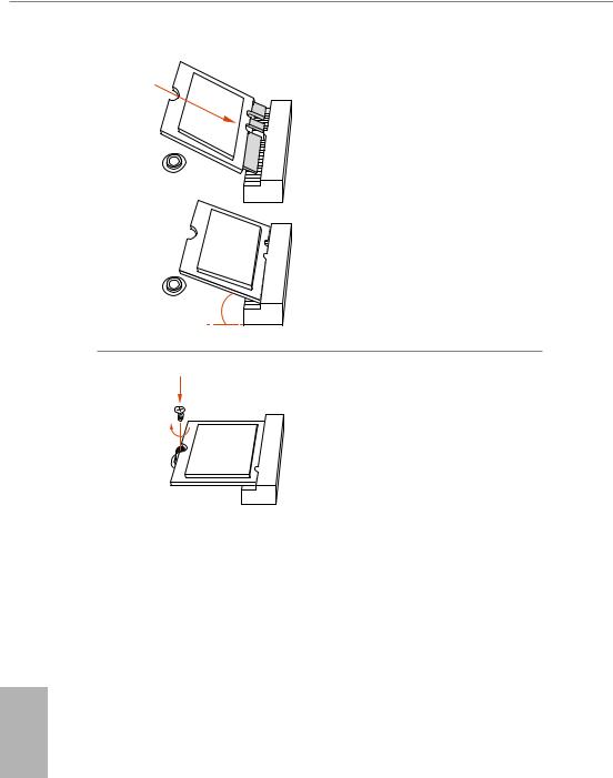
Step 3
Gently insert the WiFi/BT module or Intel® CNVi (Integrated WiFi/ BT) into the M.2 slot. Please be aware that the module only fits in one orientation.
Step 4
Tighten the screw with a screwdriver to secure the module into place. Please do not overtighten the screw as this might damage the module.
English
28
![]()
Z390 Extreme4
2.8M.2_SSD (NGFF) Module Installation Guide (M2_1 and M2_2)
The M.2, also known as the Next Generation Form Factor (NGFF), is a small size and versatile card edge connector that aims to replace mPCIe and mSATA. The Ultra M.2 Sockets (M2_1 and M2_2) support SATA3 6.0 Gb/s module and M.2 PCI Express module up to Gen3 x4 (32 Gb/s).
*M2_1, SATA3_0 and SATA3_1 share lanes. If either one of them is in use, the others will be disabled.
*M2_2, SATA3_4 and SATA3_5 share lanes. If either one of them is in use, the others will be disabled.
Installing the M.2_SSD (NGFF) Module
The following is an example of installing M.2_SSD (NGFF) module into the M2_2.
|
Step 1 |
|||||||
|
Prepare a M.2_SSD (NGFF) module |
|||||||
|
and the screw. |
|||||||
|
5 |
Step 2 |
||||||
|
4 |
|||||||
|
3 |
Depending on the PCB type and |
||||||
|
length of your M.2_SSD (NGFF) |
|||||||
|
module, find the corresponding nut |
|||||||
|
2 |
location to be used. |
||||||
|
1 |
|||||||
|
E |
D |
C |
B |
A |
|||
|
No. |
1 |
2 |
3 |
4 |
5 |
||
|
Nut Location |
A |
B |
C |
D |
E |
||
|
PCB Length |
3cm |
4.2cm |
6cm |
8cm |
11cm |
||
|
Module Type |
Type2230 |
Type 2242 |
Type2260 |
Type 2280 |
Type 22110 |
English
29

1
Step 3
Before installing a M.2 (NGFF) SSD
2
module, please loosen the screws to remove the M.2 heatsink.
1
English
|
Step4 |
|||||
|
Align and gently insert the M.2 |
|||||
|
(NGFF) SSD module into the M.2 |
|||||
|
slot. Please be aware that the M.2 |
|||||
|
(NGFF) SSD module only fits in one |
|||||
|
E |
D |
C |
B |
A |
orientation. |
E D C 20o
Step 5
Tighten the screw with a screwdriver to secure the module into place. Please do not overtighten the screw
E D
as this might damage the module.
30

M.2_SSD (NGFF) Module Support List
|
Vendor |
Interface |
P/N |
|
ADATA |
SATA3 |
AXNS330E-32GM-B |
|
ADATA |
SATA3 |
AXNS381E-128GM-B |
|
ADATA |
SATA3 |
AXNS381E-256GM-B |
|
ADATA |
SATA3 |
ASU800NS38-256GT-C |
|
ADATA |
SATA3 |
ASU800NS38-512GT-C |
|
ADATA |
PCIe3 x4 |
ASX7000NP-128GT-C |
|
ADATA |
PCIe3 x4 |
ASX8000NP-256GM-C |
|
ADATA |
PCIe3 x4 |
ASX7000NP-256GT-C |
|
ADATA |
PCIe3 x4 |
ASX8000NP-512GM-C |
|
ADATA |
PCIe3 x4 |
ASX7000NP-512GT-C |
|
Apacer |
PCIe3 x4 |
AP240GZ280 |
|
Corsair |
PCIe3 x4 |
CSSD-F240GBMP500 |
|
Crucial |
SATA3 |
CT120M500SSD4 |
|
Crucial |
SATA3 |
CT240M500SSD4 |
|
Intel |
SATA3 |
Intel SSDSCKGW080A401/80G |
|
Intel |
PCIe3 x4 |
SSDPEKKF256G7 |
|
Intel |
PCIe3 x4 |
SSDPEKKF512G7 |
|
Kingston |
SATA3 |
SM2280S3 |
|
Kingston |
PCIe3 x4 |
SKC1000/480G |
|
Kingston |
PCIe2 x4 |
SH2280S3/480G |
|
OCZ |
PCIe3 x4 |
RVD400 -M2280-512G (NVME) |
|
PATRIOT |
PCIe3 x4 |
PH240GPM280SSDR NVME |
|
Plextor |
PCIe3 x4 |
PX-128M8PeG |
|
Plextor |
PCIe3 x4 |
PX-1TM8PeG |
|
Plextor |
PCIe3 x4 |
PX-256M8PeG |
|
Plextor |
PCIe3 x4 |
PX-512M8PeG |
|
Plextor |
PCIe |
PX-G256M6e |
|
Plextor |
PCIe |
PX-G512M6e |
|
Samsung |
PCIe3 x4 |
SM961 MZVPW128HEGM (NVM) |
|
Samsung |
PCIe3 x4 |
PM961 MZVLW128HEGR (NVME) |
|
Samsung |
PCIe3 x4 |
960 EVO (MZ-V6E250) (NVME) |
|
Samsung |
PCIe3 x4 |
960 EVO (MZ-V6E250BW) (NVME) |
|
Samsung |
PCIe3 x4 |
SM951 (NVME) |
|
Samsung |
PCIe3 x4 |
SM951 (MZHPV256HDGL) |
|
Samsung |
PCIe3 x4 |
SM951 (MZHPV512HDGL) |
|
Samsung |
PCIe3 x4 |
SM951 (NVME) |
|
Samsung |
PCIe x4 |
XP941-512G (MZHPU512HCGL) |
|
SanDisk |
PCIe |
SD6PP4M-128G |
|
SanDisk |
PCIe |
SD6PP4M-256G |
|
Team |
SATA3 |
TM4PS4128GMC105 |
|
Team |
SATA3 |
TM4PS4256GMC105 |
|
Team |
SATA3 |
TM8PS4128GMC105 |
|
Team |
SATA3 |
TM8PS4256GMC105 |
31

|
TEAM |
PCIe3 x4 |
TM8FP2240G0C101 |
|
TEAM |
PCIe3 x4 |
TM8FP2480GC110 |
|
Transcend |
SATA3 |
TS256GMTS400 |
|
Transcend |
SATA3 |
TS512GMTS600 |
|
Transcend |
SATA3 |
TS512GMTS800 |
|
V-Color |
SATA3 |
VLM100-120G-2280B-RD |
|
V-Color |
SATA3 |
VLM100-240G-2280RGB |
|
V-Color |
SATA3 |
VSM100-240G-2280 |
|
V-Color |
SATA3 |
VLM100-240G-2280B-RD |
|
WD |
SATA3 |
WDS100T1B0B-00AS40 |
|
WD |
SATA3 |
WDS240G1G0B-00RC30 |
|
WD |
PCIe3 x4 |
WDS256G1X0C-00ENX0 (NVME) |
|
WD |
PCIe3 x4 |
WDS512G1X0C-00ENX0 (NVME) |
For the latest updates of M.2_SSD (NFGG) module support list, please visit our website for details: http://www.asrock.com
English
32

Z390 Extreme4
2.9 ASRock Polychrome RGB
ASRock Polychrome RGB is a lighting control utility specifically designed for unique individuals with sophisticated tastes to build their own stylish colorful lighting system. Simply by connecting the LED strip, you can customize various lighting schemes and patterns, including Static, Breathing, Strobe, Cycling, Music, Wave and more.
Connecting the LED Strip
Connect your RGB LED strips to the RGB LED Headers (RGB_LED1, RGB_LED2) on the motherboard.
RGB_LED1
1 
12V G R B
RGB_LED2
1 
12V G R B
1.Never install the RGB LED cable in the wrong orientation; otherwise, the cable may be damaged.
2.Before installing or removing your RGB LED cable, please power off your system and unplug the power cord from the power supply. Failure to do so may cause damages to motherboard components.
1.Please note that the RGB LED strips do not come with the package.
2.The RGB LED header supports standard 5050 RGB LED strip (12V/G/R/B), with a maximum power rating of 3A (12V) and length within 2 meters.
English
33

Connecting the Addressable RGB LED Strip
Connect your Addressable RGB LED strip to the Addressable LED Header (ADDR_LED1) on the motherboard.
ADDR_LED1
1
GND
DO_ADDR
VOUT
1

1.Never install the RGB LED cable in the wrong orientation; otherwise, the cable may be damaged.
2.Before installing or removing your RGB LED cable, please power off your system and unplug the power cord from the power supply. Failure to do so may cause damages to motherboard components.
1.Please note that the RGB LED strips do not come with the package.
2.The RGB LED header supports WS2812B addressable RGB LED strip (5V/Data/ GND), with a maximum power rating of 3A (5V) and length within 2 meters.
English
34

Z390 Extreme4
ASRock Polychrome RGB Utility
Now you can adjust the RGB LED color through the ASRock Polychrome RGB Utility. Download this utility from the ASRock Live Update & APP Shop and start coloring your PC style your way!
Toggle on/off the RGB LED switch
Sync RGB LED effects for all LED regions of the motherboard
Drag the tab to customize your preference.
Select a RGB LED light effect from the drop-down menu.
English
35

1 Einleitung
Vielen Dank, dass Sie sich für das Z390 Extreme4 von ASRock entschieden haben – ein zuverlässiges Motherboard, das konsequent unter der strengen Qualitätskontrolle von ASRock hergestellt wurde. Es liefert ausgezeichnete Leistung mit robustem Design, das ASRock Streben nach Qualität und Beständigkeit erfüllt.
Da die technischen Daten des Motherboards sowie die BIOS-Software aktualisiert werden können, kann der Inhalt dieser Dokumentation ohne Ankündigung geändert werden. Falls diese Dokumentation irgendwelchen Änderungen unterliegt, wird die aktualisierte Version ohne weitere Hinweise auf der ASRock-Webseite zur Verfügung gestellt. Sollten Sie technische Hilfe in Bezug auf dieses Motherboard benötigen, erhalten Sie auf unserer Webseite spezifischen Informationen über das von Ihnen verwendete Modell. Auch finden Sie eine aktuelle Liste unterstützter VGA-Karten und Prozessoren auf der ASRock-Webseite: ASRock-Webseite http://www.asrock.com.
1.1 Lieferumfang
•ASRock Z390 Extreme4-Motherboard (ATX-Formfaktor)
•ASRock Z390 Extreme4–Schnellinstallationsanleitung
•ASRock Z390 Extreme4–Support-CD
•1 x E/A-Blendenabschirmung
•4 x Serial-ATA-(SATA) Datenkabel (optional)
•1 x ASRock SLI_HB_Bridge_2S-Karte (optional)
•3 x Schrauben für M.2-Sockel (optional)
Deutsch
36

Z390 Extreme4
1.2 Technische Daten
|
Plattform |
• |
ATX-Formfaktor |
|
Prozessor |
• |
Unterstützt Intel® CoreTM-Prozessoren (Sockel 1151) der 8ten & |
|
9ten Generation |
||
|
• |
Digi Power design |
|
|
• |
12-Leistungsphasendesign |
|
|
• |
Unterstützt Intel® Turbo Boost 2.0-Technologie |
|
|
• |
Unterstützt CPUs mit freiem Multiplikator der Intel® K-Serie |
|
|
• |
Unterstützt ASRock BCLK-Übertaktung (voller Bereich) |
|
|
Chipsatz |
• |
Intel® Z390 |
|
Speicher |
• |
Dualkanal-DDR4-Speichertechnologie |
|
• |
4 x DDR4-DIMM-Steckplätze |
|
|
• |
Unterstützt DDR4 4300+(OC)*/4266(OC)/4133(OC)/4000 |
|
|
(OC)/3866(OC)/3800(OC)/3733(OC)/3600(OC)/3200(OC) |
||
|
/2933(OC)/2800(OC)/2666/2400/2133 non-ECC, |
||
|
ungepufferter Speicher |
||
|
* Weitere Informationen finden Sie in der |
||
|
Speicherkompatibilitätsliste auf der ASRock-Webseite. |
||
|
(http://www.asrock.com/) |
||
|
• Unterstützt ECC-UDIMM-Speichermodule (Betrieb im non- |
||
|
ECC-Modus) |
||
|
• Systemspeicher, max. Kapazität: 64GB |
||
|
• Unterstützt Intel® Extreme Memory Profile (XMP) 2.0 |
||
|
• |
15-μ-Goldkontakt in DIMM-Steckplätze |
|
|
Erweiter- |
• |
3 x PCI-Express 3.0-x16-Steckplätze (PCIE2/PCIE4/ |
|
ungssteck- |
PCIE6:einzeln bei x16 (PCIE2); doppelt bei x8 (PCIE2) / x8 |
|
|
platz |
(PCIE4); dreifach bei x8 (PCIE2) / x8 (PCIE4) / x4 (PCIE6))* |
|
|
* Unterstützt NVMe-SSD als Bootplatte |
• 3 x PCI-Express 3.0-x1-Steckplätze (Flexible PCIe)
• Unterstützt AMD Quad CrossFireXTM, 3-Wege-CrossFireXTM und CrossFireXTM
• Unterstützt NVIDIA® Quad SLITM und SLITM
• 1 x M.2-Sockel (Key E), unterstützt Typ-2230-Wi-Fi-/-BT- Modul und Intel® CNVi (WLAN/BT integriert)
• 15-μ-Goldkontakt in VGA-PCIe-Steckplatz (PCIE2)
Deutsch
37

Deutsch
|
Grafikkarte |
• |
Integrierte Intel® UHD Graphics-Visualisierung und VGA- |
|
Ausgänge können nur mit Prozessoren unterstützt werden, die |
||
|
GPU-integriert sind. |
||
|
• Unterstützt integrierte Intel® UHD Graphics-Visualisierung: |
||
|
Intel® Quick Sync Video mit AVC, MVC (S3D) und |
||
|
MPEG-2 Full HW Encode1, Intel® InTruTM 3D, Intel® Clear |
||
|
Video HD Technology, Intel® InsiderTM, Intel® UHD Graphics |
||
|
• |
DirectX 12 |
|
|
• HWA encodieren/decodieren: AVC/H.264, HEVC/H.265 |
||
|
8 bit, HEVC/H.265 10 bit, VP8, VP9 8 bit, VP9 10 bit (nur |
||
|
Dekodierung), MPEG2, MJPEG, VC-1 (nur Dekodierung) |
||
|
• Drei Grafikkarten-Ausgangsoptionen: D-Sub, HDMI und |
||
|
DisplayPort 1.2 |
||
|
• |
Unterstützt drei Monitore |
|
|
• Unterstützt HDMI mit maximaler Auflösung von |
||
|
4K x 2K (4096 x 2160) bei 30 Hz |
||
|
• Unterstützt DisplayPort 1.2 mit maximaler Auflösung |
||
|
von 4K x 2K (4096 x 2304) bei 60 Hz |
||
|
• Unterstützt D-Sub mit maximaler Auflösung von |
||
|
1920 x 1200 bei 60 Hz |
||
|
• Unterstützt Auto-Lippensynchronizität, hohe Farbtiefe (12 |
||
|
bpc), xvYCC und HBR (Audio mit hoher Bitrate) mit HDMI |
||
|
-Port (konformer HDMI-Monitor erforderlich) |
||
|
• Unterstützt HDCP mit HDMIund DisplayPort 1.2-Ports |
||
|
• Unterstützt 4K-Ultra-HD- (UHD) Wiedergabe mit HDMI- |
||
|
und DIsplayPort-1.2-Ports |
||
|
Audio |
• |
7.1-Kanal-HD-Audio mit Inhaltsschutz (Realtek ALC1220- |
|
Audiocodec) |
||
|
• |
Erstklassige Blu-ray-Audiounterstützung |
|
|
• |
Unterstützt Überspannungsschutz |
|
|
• Unterstützt Purity SoundTM 4 |
||
|
— Nichicon-Audiokappen der Fine Gold-Serie |
||
|
— 120-dB-SRV-DAC mit Differentialverstärker |
||
|
— NE5532 – erstklassiger Headset-Verstärker für |
Audioanschluss an der Frontblende (unterstützt Headsets mit bis zu 600 Ohm)
— Reiner Stromeingang
38
![]()
Z390 Extreme4
|
— Direct Drive Technology |
||
|
— PCB-isolierte Abschirmung |
||
|
— Impedanzerkennung am vorderen Ausgang |
||
|
— Individuelle PCB-Layer für rechten/linken Audiokanal |
||
|
— RGB-LED |
||
|
— 15-μ-Gold-Audioanschluss |
||
|
• |
Unterstützt DTS Connect |
|
|
LAN |
• |
Gigabit LAN 10/100/1000 Mb/s |
|
• Giga PHY Intel® I219V |
||
|
• |
Unterstützt Wake-On-LAN |
|
|
• Unterstützt Schutz gegen Blitzschlag/elektrostatische Entladung |
||
|
• Unterstützt energieeffizientes Ethernet 802.3az |
||
|
• |
Unterstützt PXE |
|
|
Rückblende, |
• |
2 x Antennenanschluss |
|
E/A |
• |
1 x PS/2-Maus-/Tastaturanschluss |
|
• |
1 x D-Sub-Port |
|
|
• |
1 x HDMI-Port |
|
|
• 1 x DisplayPort 1.2 |
||
|
• 1 x Optischer SPDIF-Ausgang |
||
|
• 1 x USB-3.1-Gen2-Type-A-Port (10 Gb/s) (ReDriver) |
||
|
(unterstützt Schutz gegen elektrostatische Entladung) |
||
|
• 1 x USB-3.1-Gen2-Type-C-Port (10 Gb/s) (ReDriver) |
||
|
(unterstützt Schutz gegen elektrostatische Entladung) |
||
|
• 4 x USB-3.1 Gen1-Ports (Intel® Z390) (unterstützt Schutz gegen |
||
|
elektrostatische Entladung) |
||
|
• 1 x RJ-45-LAN-Port mit LED (Aktivität/Verbindung-LED und |
||
|
Geschwindigkeit-LED) |
||
|
• HD-Audioanschlüsse: Hintere Lautsprecher / Zentral / Bass / |
||
|
Line-in / Vorderer Lautsprecher / Mikrofon |
||
|
Speicher |
• |
6 x SATA-III-6,0-Gb/s-Abschluss, unterstützt RAID (RAID |
|
0, RAID 1, RAID 5, RAID 10, Intel Rapid Storage Technology |
||
|
16), NCQ, AHCI und Hot-Plugging* |
• 2 x SATA-III-6,0-Gb/s-Anschlüsse von ASMedia ASM1061, unterstützt NCQ, AHCI und Hot-Plugging
Deutsch
39

Deutsch
*M2_1, SATA3_0 und SATA3_1 nutzen Lanes gemeinsam. Wenn einer von ihnen benutzt wird, werden die anderen deaktiviert.
*M2_2, SATA3_4 und SATA3_5 nutzen Lanes gemeinsam. Wenn einer von ihnen benutzt wird, werden die anderen deaktiviert.
•1 x Ultra-M.2-Sockel (M2_1), unterstützt M-Key-Typ- 2230/2242/2260/2280-M.2-SATA-III-6,0-Gb/s-Modul und M.2-PCI-Express-Modul bis Gen. 3 x 4 (32 Gb/s)**
•1 x Ultra-M.2-Sockel (M2_2), unterstützt M-Key-Typ- 2230/2242/2260/2280/22110-M.2-SATA-III-6,0-Gb/s-Modul und M.2-PCI-Express-Modul bis Gen. 3 x 4 (32 Gb/s)**
**Unterstützt Intel® OptaneTM-Technologie
**Unterstützt NVMe-SSD als Bootplatte
**Unterstützt ASRock U.2-Kit
|
Anschluss |
• 1 x COM-Anschluss-Stiftleiste |
•1 x TPM-Stiftleiste
•1 x Betrieb-LED- und Lautsprecher-Stiftleiste
•2 x RGB-LED-Stiftleisten
*Unterstützt insgesamt bis zu 12 V/3 A, 36-W-LED-Streifen
•1 x Adressierbare-LED-Stiftleiste
*Unterstützt insgesamt bis zu 5 V/3 A, 15-W-LED-Streifen
•1 x CPU-Lüfteranschluss (4-polig)
*Der CPU-Lüfteranschluss unterstützt einen CPU-Lüfter mit einer maximalen Lüfterleistung von 1 A (12 W).
•1 x Anschluss für CPU-/Wasserpumpenlüfter (4-polig) (intelligente Lüftergeschwindigkeitssteuerung)
*Der CPU-/Wasserpumpenlüfter unterstützt einen Wasserkühlerlüfter mit einer maximalen Lüfterleistung von 2A (24 W).
•3 x Anschlusse für Gehäuse-/Wasserpumpenlüfter (4-polig) (intelligente Lüftergeschwindigkeitssteuerung)
*Der Gehäuse-/Wasserpumpenlüfter unterstützt einen Wasserkühlerlüfter mit einer maximalen Lüfterleistung von 2A (24 W).
*CPU_FAN2/WP, CHA_FAN1/WP, CHA_FAN2/WP und CHA_ FAN3/WP können automatisch erkennen, ob ein 3- oder 4-poliger Lüfter verwendet wird.
•1 x 24-poliger ATX-Netzanschluss (hochdichter Netzanschluss).
•1 x 8-poliger 12-V-Netzanschluss (hochdichter Netzanschluss)
40

Z390 Extreme4
• 1 x 4-poliger 12-V-Netzanschluss (hochdichter Netzanschluss)
• 1 x Audioanschluss an der Frontblende (15μ goldene Audioanschluss)
• 1 x Thunderbolt Erweiterungskartenanschluss (5-polig)
• 2 x USB 2.0-Stiftleisten (unterstützt 4 USB 2.0-Ports) (Intel® Z390) (unterstützt Schutz gegen elektrostatische Entladung)
• 2 x USB 3.1 Gen1-Stiftleiste (unterstützt vier USB 3.1 Gen1-
|
Ports) (ASMedia ASM1074-Hub) (unterstützt Schutz gegen |
||
|
elektrostatische Entladung) |
||
|
• 1 x USB-3.1-Gen1-Type-C-Stiftleiste an der Frontblende (Intel® |
||
|
Z390) (unterstützt Schutz gegen elektrostatische Entladung) |
||
|
• 1 x Leistungsmodus / einfache Übertaktungsstiftleiste |
||
|
BIOS-Funk- |
• |
2 x AMI-UEFI-Legal-BIOS mit Unterstützung mehrsprachiger |
|
tion |
grafischer Benutzerschnittstellen (1 x Haupt-BIOS und 1 x |
|
|
Ausfall-BIOS) |
||
|
• Unterstützt UEFI-Technologie (zuverlässige Sicherung) |
||
|
• ACPI 6.0-konforme Aufweckereignisse |
||
|
• |
SMBIOS 2.7-Unterstützung |
|
|
• CPU-Kern/Cache, GT, DRAM, PCH 1,0 V, VCCIO, VCCST, |
||
|
VCCSA, VCCPLL, CPU intern PLL, GT PLL, Ring-PLL, Sys- |
||
|
temagent-PLL, Speichercontroller-PLL Spannungsmehrfachan- |
||
|
passung |
||
|
Hard- |
• |
Temperaturerkennung: CPU-, CPU-/Wasserpumpen-, Ge- |
|
wareüberwa- |
häuse-/Wasserpumpenlüfter |
|
|
chung |
• |
Lüftertachometer: CPU-, CPU-/Wasserpumpen-, Gehäuse-/ |
|
Wasserpumpenlüfter |
||
|
• Lautloser Lüfter (automatische Anpassung der Gehäuselüfterg- |
||
|
eschwindigkeit durch CPU-Temperatur): CPU-, CPU-/Wasser- |
||
|
pumpen-, Gehäuse-/Wasserpumpenlüfter |
||
|
• |
Mehrfachgeschwindigkeitssteuerung: CPU-, CPU-/Wasser- |
|
|
pumpen-, Gehäuse-/Wasserpumpenlüfter |
||
|
• Spannungsüberwachung: +12 V, +5 V, +3,3 V, CPU Vcore, |
||
|
DRAM, VPPM, PCH 1,0V, VCCSA, VCCST, VCCIO |
||
|
Betriebssys- |
• |
Microsoft® Windows® 10, 64 Bit |
|
tem |
||
|
Zertifizierun- |
• |
FCC, CE |
|
gen |
• |
ErP/EuP ready (ErP/EuP ready-Netzteil erforderlich) |
Deutsch
41

* Detaillierte Produktinformationen finden Sie auf unserer Webseite: http://www.asrock.com
Bitte beachten Sie, dass mit einer Übertaktung, zu der die Anpassung von BIOS-Einstellungen, die Anwendung der Untied Overclocking Technology oder die Nutzung von Übertaktungswerkzeugen von Drittanbietern zählen, bestimmte Risiken verbunden sind. Eine Übertaktung kann sich auf die Stabilität Ihres Systems auswirken und sogar Komponenten und Geräte Ihres Systems beschädigen. Sie sollte auf eigene Gefahr und eigene Kosten durchgeführt werden. Wir übernehmen keine Verantwortung für mögliche Schäden, die durch eine Übertaktung verursacht wurden.
Deutsch
42

Z390 Extreme4
1.3 Jumpereinstellung
Die Abbildung zeigt, wie die Jumper eingestellt werden. Wenn die Jumper-Kappe auf den Kontakten angebracht ist, ist der Jumper „kurzgeschlossen“. Wenn keine Jumper-Kappe auf den Kontakten angebracht ist, ist der Jumper „offen“.
|
CMOS-löschen-Jumper |
Kurzgeschlossen: CMOS löschen |
|
|
(CLRCMOS1) |
2-poliger Jumper |
Offen: Standard |
|
(siehe S. 1, Nr. 29) |
||
CLRCMOS1 ermöglicht Ihnen die Löschung der Daten im CMOS. Die Daten im CMOS beinhaltet Systemeinrichtungsinformationen, wie Systemkennwort, Datum, Zeit und Systemeinrichtungsparameter. Zum Löschen und Rücksetzen der Systemparameter auf die Standardeinrichtung schalten Sie den Computer bitte ab und ziehen das Netzkabel; schließen Sie dann die Kontakte an CLRCMOS1 3 Sekunden mit einer Jumper-Kappe kurz. Bitte denken Sie daran, die Jumper-Kappe nach der CMOS-Löschung zu entfernen. Falls Sie den CMOS direkt nach Abschluss der BIOS-Aktualisierung löschen müssen, starten Sie das System zunächst; fahren Sie es dann vor der CMOS-Löschung herunter.
Deutsch
43

1.4 Integrierte Stiftleisten und Anschlüsse
Integrierte Stiftleisten und Anschlüsse sind KEINE Jumper. Bringen Sie KEINE Jumper-Kappen an diesen Stiftleisten und Anschlüssen an. Durch Anbringen von Jumper-Kappen an diesen Stiftleisten und Anschlüssen können Sie das Motherboard dauerhaft beschädigen.
Systemblende-Stiftleiste
(9-polig, PANEL1)
(siehe S. 1, Nr. 17)
PLED+ PLED-
PWRBTN#
GND
1
GND RESET#
GND HDLED-
HDLED+
Verbinden Sie Ein-/Austaste, Reset-Taste und Systemstatusanzeige am Gehäuse entsprechend der nachstehenden Pinbelegung mit dieser Stiftleiste. Beachten Sie vor Anschließen der Kabel die positiven und negativen Kontakte.
PWRBTN (Ein-/Austaste):
Mit der Ein-/Austaste an der Frontblende des Gehäuses verbinden. Sie können die Abschaltung Ihres
Systems über die Ein-/Austaste konfigurieren.
RESET (Reset-Taste):
Mit der Reset-Taste an der Frontblende des Gehäuses verbinden. Starten Sie den Computer über die
Reset-Taste neu, wenn er abstürzt oder sich nicht normal neu starten lässt.
PLED (Systembetriebs-LED):
Mit der Betriebsstatusanzeige an der Frontblende des Gehäuses verbinden. Die LED leuchtet, wenn das System läuft. Die LED blinkt, wenn sich das System im S1/S3-Ruhezustand befindet. Die LED ist aus, wenn sich das System im S4-Ruhezustand befindet oder ausgeschaltet ist (S5).
HDLED (Festplattenaktivitäts-LED):
Mit der Festplattenaktivitäts-LED an der Frontblende des Gehäuses verbinden. Die LED leuchtet, wenn die Festplatte Daten liest oder schreibt.
Das Design der Frontblende kann je nach Gehäuse variieren. Ein Frontblendenmodul besteht hauptsächlich aus Ein-/Austaste, Reset-Taste, Betrieb-LED, Festplattenaktivität-LED, Lautsprecher etc. Stellen Sie beim Anschließen Ihres Frontblendenmoduls an diese Stiftleiste sicher, dass Kabelund Pinbelegung richtig abgestimmt sind.
Deutsch
44

Betrieb-LED- und Lautsprecher-Stiftleiste (7-polig, SPK_PLED1) (siehe S. 1, Nr. 18)
SPEAKER
DUMMY DUMMY +5V
1
PLED+
PLED+ PLED-
Z390 Extreme4
Bitte verbinden Sie die Be- trieb-LED des Gehäuses und den Gehäuselautsprecher mit dieser Stiftleiste.
|
Serial-ATA-III-Anschlüsse |
4 |
5 |
Diese acht SATA-III-Anschlüsse |
|
|
(SATA3_4_5: |
_ |
_ |
unterstützen SATA-Datenkabel |
|
|
SATA3 |
SATA3 |
|||
|
siehe S. 1, Nr. 11) |
für interne Speichergeräte mit |
|||
|
(SATA3_2_3: |
einer Datenübertragungsgeschw |
|||
|
siehe S. 1, Nr. 12) |
2 |
3 |
indigkeit bis 6,0 Gb/s. |
|
|
(SATA3_0_1: |
SATA3 |
SATA3 |
* M2_1, SATA3_0 und SATA3_1 |
|
|
siehe S. 1, Nr. 13) |
nutzen Lanes gemeinsam. Wenn |
|||
|
(SATA3_A1_A2: |
einer von ihnen benutzt wird, |
|||
|
siehe S. 1, Nr. 14) |
0 |
1 |
werden die anderen deaktiviert. |
|
|
SATA3 |
SATA3 |
* M2_2, SATA3_4 und SATA3_5 |
||
|
nutzen Lanes gemeinsam. Wenn |
||||
|
A1 |
A2 |
einer von ihnen benutzt wird, |
||
|
werden die anderen deaktiviert. |
||||
|
SATA3 |
SATA3 |
*Nutzen Sie zum Minimieren |
||
|
der Startzeit Intel®-Z390-SATA- |
||||
|
Ports (SATA3_0) für Ihre SSDs. |
USB 2.0-Stiftleisten
(9-polig, USB_1_2)
(siehe S. 1, Nr. 20)
(9-polig, USB_3_4)
(siehe S. 1, Nr. 19)
USB_PWR
P- P+ GND DUMMY
1
GND
USBP_—PWRP+
Es gibt zwei Stiftleisten an diesem Motherboard. Jede USB 2.0-Stiftleiste kann zwei Ports unterstützen.
Deutsch
45

Deutsch
USB 3.1 Gen1-Stiftleisten
(19-polig, USB3_5_6)
(siehe S. 1, Nr.
(19-polig, USB3_7_8)
(siehe S. 1, Nr. 9)
Vbus
IntA_PA_SSRX-
IntA_PA_SSRX+
GND
IntA_PA_SSTX-
IntA_PA_SSTX+
GND
IntA_PA_D-
IntA_PA_D+
Vbus
IntA_PB_SSRX-
IntA_PB_SSRX+
GND
IntA_PB_SSTX-
IntA_PB_SSTX+
GND
IntA_PB_D-
IntA_PB_D+
Dummy
1
Es gibt zwei Stiftleisten an diesem Motherboard. Jede USB 3.1 Gen1Stiftleiste kann zwei Ports unterstützen.
|
Type-C-USB-3.1 |
Es gibt eine Type-C-USB-3.1 |
||||||||||
|
Gen1-Stiftleiste für die |
Gen1-Stiftleiste für die |
||||||||||
|
Frontblende |
Frontblende an diesem |
||||||||||
|
(26-polig, USB31_TC_2) |
Motherboard. Diese Stiftleiste |
||||||||||
|
(siehe S. 1, Nr. 10) |
dient dem Anschluss eines |
||||||||||
|
USB-3.1 Gen1-Moduls für |
|||||||||||
|
zusätzliche USB-3.1 Gen1- |
|||||||||||
|
Ports. |
|||||||||||
|
Audiostiftleiste |
PRESENCE# |
Diese Stiftleiste dient |
|||||||||
|
GND |
|||||||||||
|
(Frontblende) |
MIC_RET |
dem Anschließen von |
|||||||||
|
OUT_RET |
|||||||||||
|
(9-polig, HD_AUDIO1) |
Audiogeräten an der |
||||||||||
|
(siehe S. 1, Nr. 28) |
1 |
Frontblende. |
|||||||||
|
OUT2_L |
|||||||||||
|
J_SENSE |
|||||||||||
|
OUT2_R |
|||||||||||
|
MIC2_R |
|||||||||||
|
MIC2_L |
1. High Definition Audio unterstützt Anschlusserkennung, der Draht am Gehäuse muss dazu jedoch HDA unterstützt. Bitte befolgen Sie zum Installieren Ihres Systems die Anweisungen in unserer Anleitung und der Anleitung zum Gehäuse.
2.Bei Nutzung eines AC’97-Audiopanels dieses bitte anhand folgender Schritte an der Audiostiftleiste der Frontblende installieren:
A.Mic_IN (Mikrofon) mit MIC2_L verbinden.
B.Audio_R (RIN) mit OUT2_R und Audio_L (LIN) mit OUT2_L verbinden.
C.Erde (GND) mit Erde (GND) verbinden.
D.MIC_RET und OUT_RET sind nur für das HD-Audiopanel vorgesehen. Sie müssen sie nicht für das AC’97-Audiopanel verbinden.
E.Rufen Sie zum Aktivieren des vorderen Mikrofons das „FrontMic (Vorderes Mikro-
fon)“-Register in der Realtek-Systemsteuerung auf und passen „Recording Volume (Aufnahmelautstärke)“ an.
46

Z390 Extreme4
Gehäuse-/Wasserpump- en-Lüfteranschlusse (4-polig, CHA_FAN1/WP) (siehe S. 1, Nr. 30)
(4-polig, CHA_FAN2/WP) (siehe S. 1, Nr. 23)
GND
FAN_VOLTAGE FAN_SPEED
FAN_SPEED_CONTROL
1 2 3 4
GND
FAN_VOLTAGE FAN_SPEED
FAN_SPEED_CONTROL
1 2 3 4
Dieses Motherboard bietet drei 4-poligen Wasserkühlung-Ge- häuselüfteranschluss. Falls
Sie einen 3-poligen GehäuseWasserkühlerlüfter anschließen möchten, verbinden Sie ihn bitte mit Kontakt 1 bis 3.
|
(4-polig, |
GND |
|||
|
FAN_VOLTAGE |
||||
|
CHA_FAN3/WP) |
FAN_SPEED |
|||
|
(siehe S. 1, Nr. 16) |
FAN_SPEED_CONTROL |
|||
|
1 |
2 |
3 |
4 |
|
CPU-Lüfteranschluss
(4-polig, CPU_FAN1)
(siehe S. 1, Nr. 3)
FAN_SPEED_CONTROL CPU_FAN_SPEED FAN_VOLTAGE
GND
1 2 3 4
Dieses Motherboard bietet einen 4-poligen CPU-Lüfteran- schluss (lautloser Lüfter). Falls Sie einen 3-poligen CPU-Lüfter anschließen möchten, verbinden Sie ihn bitte mit Kontakt 1 bis 3.
|
CPU-/Wasserpumpen- |
||||
|
Lüfteranschluss |
FAN_SPEED_CONTROL |
4 |
||
|
(4-polig, CPU_FAN2/WP) |
CPU_FAN_SPEED |
3 |
||
|
FAN_VOLTAGE |
2 |
|||
|
(siehe S. 1, Nr. 4) |
GND |
1 |
||
Dieses Motherboard bietet einen 4-poligen Was- serkühlung-CPU-Lüfteran-
schluss. Falls Sie einen 3-poligen CPU-Wasserkühlerlüfter anschließen möchten, verbinden Sie ihn bitte mit Kontakt 1 bis 3.
|
ATX-Netzanschluss |
12 |
24 |
Dieses Motherboard bietet |
|
(24-polig, ATXPWR1) |
einen 24-poligen ATX-Net- |
||
|
(siehe S. 1, Nr. 7) |
zanschluss. Bitte schließen Sie |
||
|
es zur Nutzung eines 20-pol- |
|||
|
igen ATX-Netzteils entlang |
|||
|
1 |
13 |
Kontakt 1 und Kontakt 13 an. |
|
Deutsch
47

Deutsch
ATX-12-V-Netzanschluss
(8-polig, ATX12V1)
(siehe S. 1, Nr. 1)
Dieses Motherboard bietet einen 8-poligen ATX-12-V-Net- zanschluss. Bitte schließen Sie es zur Nutzung eines 4-poligen ATX-Netzteils entlang Kontakt 1 und Kontakt 5 an.
|
ATX-12-V-Netzanschluss |
An diesen Anschluss schließen |
|||||||||
|
(4-polig, ATX12V2) |
Sie ein ATX-12 V-Netzteil an. |
|||||||||
|
(siehe S. 1, Nr. 2) |
*Der Netzteilstecker passt nur |
|||||||||
|
in einer Richtung in diesen |
||||||||||
|
Anschluss. |
||||||||||
|
Thunderbolt- |
Bitte verbinden Sie eine |
|||||||||
|
Erweiterungskarten |
Thunderbolt™-Erweiterungskarte |
|||||||||
|
anschlüsse |
über das GPIO-Kabel mit diesem |
|||||||||
|
(5-polig, TB1) |
Thunderbolt-AIC-Anschluss. |
|||||||||
|
(siehe S. 1, Nr. 24) |
*Bitte installieren Sie die |
|||||||||
|
Thunderbolt™-AIC-Karte am |
||||||||||
|
PCIE6 (Standardsteckplatz). |
Serieller-Port-Stiftleiste
(9-polig, COM1)
(siehe S. 1, Nr. 21)
RRXD1
DDTR#1
DDSR#1
CCTS#1
1
RRI#1
RRTS#1 GND
TTXD1
DDCD#1
Diese COM1-Stiftleiste unterstützt ein Modul für serielle Ports.
|
TPM-Stiftleiste |
# |
PCICLK |
Dieser Anschluss unterstützt das |
||||||||||||||||
|
(17-polig, TPMS1) |
GND |
+3VSB |
LAD0 |
+3V |
LAD3 |
PCIRST |
FRAME |
Trusted Platform Module-(TPM) |
|||||||||||
|
(siehe S. 1, Nr. 22) |
1 System, das Schlüssel, digitale |
||||||||||||||||||
|
Zertifikate, Kennwörter und Dat- |
|||||||||||||||||||
|
GND |
SERIRQ# PWRDWNS # |
GND |
LAD1 |
LAD2 |
DATASMBMAIN |
SMBCLK MAIN |
DGN |
en sicher aufbewahren kann. Ein |
|||||||||||
|
Stärkung der Netzwerksicherheit, |
|||||||||||||||||||
|
TPM-System hilft zudem bei der |
schützt digitale Identitäten und gewährleistet die Plattformintegrität.
48
 Loading…