Посмотреть инструкция для Asus H61M-K бесплатно. Руководство относится к категории материнские платы, 6 человек(а) дали ему среднюю оценку 8.6. Руководство доступно на следующих языках: английский. У вас есть вопрос о Asus H61M-K или вам нужна помощь? Задайте свой вопрос здесь
Не можете найти ответ на свой вопрос в руководстве? Вы можете найти ответ на свой вопрос ниже, в разделе часто задаваемых вопросов о Asus H61M-K.
Какая ширина Asus H61M-K?
Какая толщина Asus H61M-K?
Инструкция Asus H61M-K доступно в русский?
Не нашли свой вопрос? Задайте свой вопрос здесь
-
Contents
-
Table of Contents
-
Bookmarks
Quick Links
Related Manuals for Asus H61M-K
Summary of Contents for Asus H61M-K
-
Page 1
H61M-K… -
Page 2
Product warranty or service will not be extended if: (1) the product is repaired, modified or altered, unless such repair, modification of alteration is authorized in writing by ASUS; or (2) the serial number of the product is defaced or missing. -
Page 3: Table Of Contents
Contents Safety information …………………. vi About this guide ………………….vii H61M-K specifications summary …………….ix Package contents …………………. xii Product introduction Special features ……………….. 1-1 1.1.1 Product highlights …………….1-1 1.1.2 ASUS Exclusive Features …………… 1-2 Before you proceed ………………1-4 Motherboard overview ……………..
-
Page 4
Managing and updating your BIOS …………. 2-1 2.1.1 ASUS Update utility ……………. 2-1 2.1.2 ASUS EZ Flash 2 …………….2-2 2.1.3 ASUS CrashFree BIOS 3 utility …………2-3 2.1.4 ASUS BIOS Updater …………… 2-4 BIOS setup program ………………2-6 Main menu ………………..2-10 2.3.1 System Language [English] ………… -
Page 5
2.7.10 Boot Option Priorities …………..2-33 2.7.11 Boot Override …………….2-33 Tools menu ………………..2-33 2.8.1 ASUS EZ Flash 2 Utility …………..2-33 2.8.2 ASUS SPD Information …………..2-33 2.8.3 ASUS O.C. Profile …………….. 2-34 Exit menu ………………..2-35 Appendices Notices …………………… -
Page 6: Safety Information
Safety information Electrical safety • To prevent electrical shock hazard, disconnect the power cable from the electrical outlet before relocating the system. • When adding or removing devices to or from the system, ensure that the power cables for the devices are unplugged before the signal cables are connected. If possible, disconnect all power cables from the existing system before you add a device.
-
Page 7: About This Guide
Refer to the following sources for additional information and for product and software updates. ASUS websites The ASUS website provides updated information on ASUS hardware and software products. Refer to the ASUS contact information. Optional documentation Your product package may include optional documentation, such as warranty flyers, that may have been added by your dealer.
-
Page 8: Conventions Used In This Guide
Conventions used in this guide To ensure that you perform certain tasks properly, take note of the following symbols used throughout this manual. DANGER/WARNING: Information to prevent injury to yourself when trying to complete a task. CAUTION: Information to prevent damage to the components when trying to complete a task IMPORTANT: Instructions that you MUST follow to complete a task.
-
Page 9: H61M-K Specifications Summary
2 x DIMMs, max. 16GB, DDR3 1600 / 1333 / 1066 MHz, non-ECC, un- buffered memory Dual-channel memory architecture Refer to www.asus.com for the latest Memory QVL (Qualified Vendors • List). When you install a total memory of 4GB capacity or more, Windows •…
-
Page 10
H61M-K specifications summary ASUS unique ASUS Anti-Surge Protection features ASUS UEFI BIOS (EZ Mode) ASUS MyLogo 2 ASUS EZ-Flash 2 ASUS Fan Xpert ASUS AI Charger ASUS Crash Free BIOS3 ASUS AI Suite II ASUS Network iControl* ASUS Webstorage • The Network iControl feature does not support Windows XP/Vista ®… -
Page 11
BIOS features 64 Mb Flash ROM, UEFI BIOS, PnP, DMI v2.0, WfM 2.0, ACPI v2.0a, SM BIOS v2.7, SLP 3.0, EUP-ready, Multi-language BIOS, ASUS EZ Flash 2, ASUS CrashFree BIOS 3, F12 PrintScreen function, F3 Shortcut function, and ASUS DRAM SPD (Serial Presence Detect) memory… -
Page 12: Package Contents
SB_PWR USB56 USB78 64Mb BIOS AAFP SPEAKER ASUS H61M-K motherboard 2 x Serial ATA 3 Gb/s cables 1 x I/O Shield User Guide Support DVD • If any of the above items is damaged or missing, contact your retailer. •…
-
Page 13: Product Introduction
Your computer can receive fresh updates for selected applications, even when the system is in sleep mode. This means less time waiting for applications to update and sync with the cloud, leading to a more efficient computing experience. ASUS H61M-K…
-
Page 14: Asus Exclusive Features
ASUS Exclusive Features ASUS UEFI BIOS (EZ Mode) ASUS UEFI BIOS, a UEFI compliant architecture, offers the first mouse-controlled intuitive graphical BIOS interface that goes beyond the traditional keyboard-only BIOS controls, providing you with more flexibility, convenience, and easy to navigate EFI BIOS than the traditional BIOS versions.
-
Page 15: Asus Mylogo2
DVD or a USB flash disk that contains the BIOS file. ASUS EZ Flash 2 ASUS EZ Flash 2 is a user-friendly utility that allows you to update the BIOS without using a bootable floppy disk or an OS-based utility.
-
Page 16: Before You Proceed
ON, in sleep mode, or in soft-off mode. This is a reminder that you should shut down the system and unplug the power cable before removing or plugging in any motherboard component. The illustration below shows the location of the onboard LED. SB_PWR H61M-K Standby Power Powered Off H61M-K Onboard LED Chapter 1: Product introduction…
-
Page 17: Motherboard Overview
Screw holes Place six screws into the holes indicated by circles to secure the motherboard to the chassis. DO NOT overtighten the screws! Doing so can damage the motherboard. Place this side towards the rear of the chassis H61M-K ASUS H61M-K…
-
Page 18: Motherboard Layout
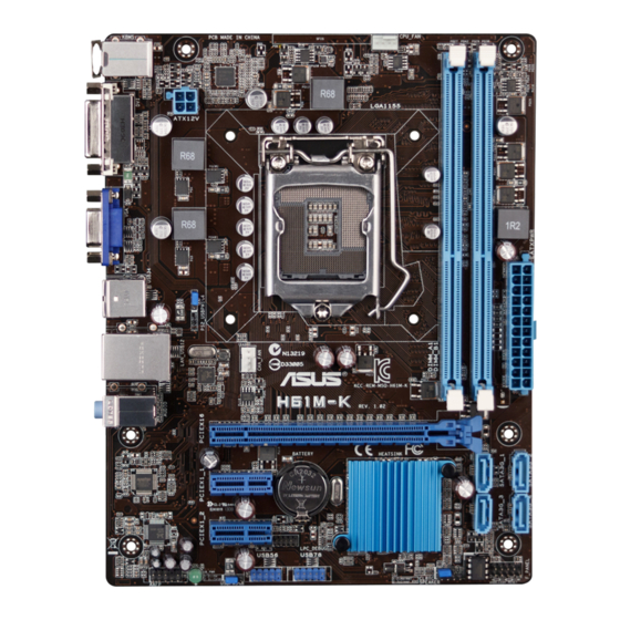
1.3.3 Motherboard layout 17.5cm(6.9in) KBMS CPU_FAN 8876 ATX12V USB34 LAN_USB12 CHA_FAN 8111F H61M-K AUDIO PCIEX16 Super PCIEX1_1 BATTERY Intel ® PCIEX1_2 SB_PWR USB56 USB78 64Mb BIOS AAFP SPEAKER Chapter 1: Product introduction…
-
Page 19: Layout Contents
Contact your retailer immediately if the PnP cap is missing, or if you see any damage to the PnP cap/socket contacts/motherboard components. ASUS will shoulder the cost of repair only if the damage is shipment/ transit-related.
-
Page 20: Cpu Installation
1.4.1 CPU installation The LGA1156 CPU is not compatible with the LGA1155 socket. DO NOT install an LGA1156 CPU on the LGA1155 socket. Chapter 1: Product introduction…
-
Page 21
ASUS H61M-K… -
Page 22: Cpu Heatsink And Fan Assembly Installation
1.4.2 CPU heatsink and fan assembly installation Apply the Thermal Interface Material to the CPU heatsink and CPU before you install the heatsink and fan if necessary. To install the CPU heatsink and fan assembly Chapter 1: Product introduction 1-10…
-
Page 23
To uninstall the CPU heatsink and fan assembly ASUS H61M-K 1-11… -
Page 24: System Memory
DDR2 DIMM socket. DDR3 modules are developed for better performance with less power consumption. The figure illustrates the location of the DDR3 DIMM sockets: Channel Sockets Channel A DIMM_A1 Channel B DIMM_B1 H61M-K H61M-K 240-pin DDR3 DIMM sockets Chapter 1: Product introduction 1-12…
-
Page 25: Memory Configurations
• For system stability, use a more efficient memory cooling system to support a full memory load (2 DIMMs) or overclocking condition. H61M-K Motherboard Qualified Vendors Lists (QVL) DDR3 2666 (O.C.) MHz capability DIMM socket SS/DS Chip support (Optional) Vendors Part No.
-
Page 26
DDR3-2600 MHz capability DIMM socket support Chip Chip (Optional) Vendors Part No. Size SS/DS Timing Voltage Brand 1 DIMM 2 DIMMs 10-12- G.SKILL F3-2600CL10Q-16GBZMD(XMP) 16GB(4x4GB) 1.65V • • 12-31 G.SKILL F3-2600CL11Q-32GBZHD(XMP) 32GB(8GBx4) 11-13-13-35 1.65V • • DDR3-2400 MHz capability DIMM socket support Chip Chip (optional) -
Page 27
1.5V · · G.SKILL F3-14900CL9Q-8GBXL(XMP) 8GB(2GBx4) 9-9-9-24 1.6V · · KINGSTON KHX1866C9D3K4/16GX(XMP) 16GB(4GBx4) 1.65V · · KINGSTON KHX1866C11D3P1K2/8G 8GB(4GBx2) 1.5V · KINGSTON KHX1866C9D3K2/8GX(XMP) 8GB(4GBX2) 1.65V · Team TLD34G1866H9KBK 9-11-9-27 1.5V · Team TLD38G1866HC10SBK 10-11-10-30 1.5V · · ASUS H61M-K 1-15… -
Page 28
DDR3-1800 MHz capability DIMM socket support Chip Chip (Optional) Vendors Part No. Size SS/DS Timing Voltage Brand 1 DIMM 2 DIMMs Kingston KHX18C10T3K4/32X 1.5V • • DDR3-1600 MHz capability DIMM socket support Vendors Part No. Size Chip Brand Chip NO. Timing Voltage (optional) -
Page 29
AD3U1600W4G11-B ADATA F209X8BR6413 · · ADATA AD3U1600C4G11-B · · ADATA AD3U1600W8G11-B ADATA F211X8B0640A · · SanMax SMD-4G68HP-16KZ HYNIX H5TQ2G83BFR PBC · · TEAM TED34G1600HC11BK 11-11-11-28 · · TEAM TLD34G1600HC9BK(XMP) 9-9-24 1.5V · · Team TED38G1600HC11BK 11-11-11-28 · ASUS H61M-K 1-17… -
Page 30
DDR3-1333 MHz capability DIMM socket Chip support(optional) Vendors Part No. Size SS/DS Chip No. Timing Voltage Brand 1DIMM 2DIMMs A-DATA AD3U1333C2G9 A-DATA 3CCD-1509HNA1126L · · A-DATA AX3U1333C2G9-BP · · Apacer 78.A1GC6.9L1 Apacer AM5D5808DEWSBG · · Apacer 78.A1GC6.9L1 Apacer AM5D5808FEQSBG · ·… -
Page 31
1 DIMM: Supports one module inserted into either slot as single-channel memory configuration. • 2 DIMMs: Supports one pair of modules inserted into both the blue slots as one pair of dual-channel memory configuration. Visit the ASUS website at www.asus.com for the latest QVL. ASUS H61M-K 1-19… -
Page 32: Installing A Dimm
1.5.3 Installing a DIMM To remove a DIMM Chapter 1: Product introduction 1-20…
-
Page 33: Expansion Slots
IRQ assignments. Otherwise, conflicts will arise between the two PCI groups, making the system unstable and the card inoperable. 1.6.3 PCI Express 2.0 x1 slot This motherboard supports PCI Express 2.0 x1 network cards, SCSI cards, and other cards that comply with the PCI Express specifications. ASUS H61M-K 1-21…
-
Page 34: Pci Express 3.0/2.0 X16 Slot
1.6.4 PCI Express 3.0/2.0 x16 slot This motherboard has a PCI Express 3.0/2.0 x16 slot that supports PCI Express 3.0/2.0 x16 graphic cards complying with the PCI Express specifications. PCIe 3.0 speed is supported by Intel 3rd generation Core™ processors. ®…
-
Page 35: Clear Rtc Ram
H61M-K Normal Clear RTC (Default) H61M-K Clear RTC RAM To erase the RTC RAM: Turn OFF the computer and unplug the power cord. Move the jumper cap from pins 1-2 (default) to pins 2-3. Keep the cap on pins 2-3 for about 5~10 seconds, then move the cap back to pins 1-2.
-
Page 36: Connectors
Connectors 1.8.1 Rear panel ports PS/2 Mouse port. This port connects to a PS/2 mouse. LAN (RJ-45) port. This port allows Gigabit connection to a Local Area Network (LAN) through a network hub. Refer to the table below for the LAN port LED indications. LAN port LED indications Speed Activity Link…
-
Page 37: Front Panel Audio Connector
H61M-K HD-audio-compliant Legacy AC’97 pin definition compliant definition H61M-K Front panel audio connector • We recommend that you connect a high-definition front panel audio module to this connector to avail of the motherboard’s high-definition audio capability. • If you want to connect a high-definition front panel audio module to this connector, set the Front Panel Type item in the BIOS setup to [HD].
-
Page 38
• If you are uncertain about the minimum power supply requirement for your system, refer to the Recommended Power Supply Wattage Calculator at http://support.asus. com/PowerSupplyCalculator/PSCalculator.aspx?SLanguage=en-us for details. Chapter 1: Product introduction… -
Page 39: Intel H61 Serial Ata 3.0Gb/S Connectors
(Default) USBPW5-8 H61M-K +5VSB (Default) H61M-K USB Device Wake Up • The USB device wake-up feature requires a power supply that can provide 500mA on the +5VSB lead for each USB port; otherwise, the system would not power up. •…
-
Page 40: Cpu And Chassis Fan Connectors
• The two fan connectors support fans of maximum 2A (24 W) fan power. • Both the 4-pin CPU fan and 4-pin chassis fan are supported by the ASUS Fan Xpert feature. USB connectors (10-1 pin USB56, USB78) These connectors are for USB 2.0 ports. Connect the USB module cable to any of these connectors, then install the module to a slot opening at the back of the system chassis.
-
Page 41: System Panel Connector
PIN 1 H61M-K +HD_LED RESET H61M-K System panel connector • System power LED (2-pin +PWR_LED-) This 2-pin connector is for the system power LED. Connect the chassis power LED cable to this connector. The system power LED lights up when you turn on the system power, and blinks when the system is in sleep mode.
-
Page 42: Software Support
The contents of the Support DVD are subject to change at any time without notice. Visit the ASUS website at www.asus.com for updates. To run the Support DVD Place the Support DVD into the optical drive.
-
Page 43: Bios Information
BIOS in the future. Copy the original motherboard BIOS using the ASUS Update utility. 2.1.1 ASUS Update utility The ASUS Update is a utility that allows you to manage, save, and update the motherboard BIOS in Windows environment. ®…
-
Page 44: Asus Ez Flash 2
Follow the onscreen instructions to complete the updating process. 2.1.2 ASUS EZ Flash 2 The ASUS EZ Flash 2 feature allows you to update the BIOS without using an OS-based utility. Before you start using this utility, download the latest BIOS file from the ASUS website at www.asus.com.
-
Page 45: Asus Crashfree Bios 3 Utility
2.1.3 ASUS CrashFree BIOS 3 utility The ASUS CrashFree BIOS 3 is an auto recovery tool that allows you to restore the BIOS file when it fails or gets corrupted during the updating process. You can restore a corrupted BIOS file using the motherboard support DVD or a USB flash drive that contains the updated BIOS file.
-
Page 46: Asus Bios Updater
2.1.4 ASUS BIOS Updater ASUS BIOS Updater allows you to update BIOS in DOS environment. This utility also allows you to copy the current BIOS file that you can use as a backup when the BIOS fails or gets corrupted during the updating process.
-
Page 47: Updating The Bios File
Ensure to load the BIOS default settings to ensure system compatibility and stability. Select the Load Optimized Defaults item under the Exit menu. Refer to section 2.9 Exit menu for details. • Ensure to connect all SATA hard disk drives after updating the BIOS file if you have disconnected them. ASUS H61M-K…
-
Page 48: Bios Setup Program
The BIOS setup screens shown in this section are for reference purposes only, and may not exactly match what you see on your screen. Visit the ASUS website at www.asus.com to download the latest BIOS file for this • motherboard.
-
Page 49
Advanced mode right hand side functions • The boot device options vary depending on the devices you installed to the system. The Boot Menu(F8) button is available only when the boot device is installed to the • system. ASUS H61M-K… -
Page 50: Advanced Mode
The Advanced Mode provides advanced options for experienced end-users to configure the BIOS settings. The figure below shows an example of the Advanced Mode. Refer to the following sections for the detailed configurations. To access the EZ Mode, click Exit, then select ASUS EZ Mode. Back button Menu items…
-
Page 51: Menu Items
You cannot select an item that is not user-configurable. A configurable field is highlighted when selected. To change the value of a field, select it and press <Enter> to display a list of options. ASUS H61M-K…
-
Page 52: Main Menu
Main menu The Main menu screen appears when you enter the Advanced Mode of the BIOS Setup program. The Main menu provides you an overview of the basic system information, and allows you to set the system date, time, language, and security settings. 2.3.1 System Language [English] Allows you to choose the BIOS language version from the options.
-
Page 53: Administrator Password
To clear the user password, follow the same steps as in changing a user password, but press <Enter> when prompted to create/confirm the password. After you clear the password, the User Password item on top of the screen shows Not Installed. ASUS H61M-K 2-11…
-
Page 54: Ai Tweaker Menu
Ai Tweaker menu The Ai Tweaker menu items allow you to configure overclocking-related items. Be cautious when changing the settings of the Ai Tweaker menu items. Incorrect field values can cause the system to malfunction. The configuration options for this section vary depending on the CPU and DIMM model you installed on the motherboard.
-
Page 55: Memory Frequency [Auto]
Allows you to enable or disable the Enhanced Intel SpeedStep Technology (EIST). ® [Disabled] Disables this function. [Enabled] The operating system dynamically adjusts the processor voltage and core frequency which may result in decreased average consumption and decreased average heat production. ASUS H61M-K 2-13…
-
Page 56
Turbo Mode [Enabled] [Enabled] Allows processor cores to run faster than marked frequency in specific conditions. [Disabled] Disables this function. The first three items appear only when you set the Turbo Mode items to [Enabled]. Long Duration Power Limit [Auto] Allows you to limit the turbo ratio’s long duration power. -
Page 57: Advanced Menu
The items shown in submenu may be different due to the CPU you installed. Intel Adaptive Thermal Monitor [Enabled] [Enabled] Enables the overheated CPU to throttle its clock speed to cool down. [Disabled] Disables the CPU thermal monitor function. ASUS H61M-K 2-15…
-
Page 58
Active Processor Cores [All] Allows you to choose the number of CPU cores to activate in each processor package. Configuration options: [All] [1] [2] [3] Limit CPUID Maximum [Disabled] [Enabled] Allows legacy operating systems to boot even without support for CPUs with extended CPUID functions. -
Page 59: Cpu Power Management Configuration
Allows you to disable or enable the CPU C6 report to OS. [Auto] Set this item automatically. [Disabled] Disables this function. [Enabled] Enables the C6 report function. This item should be enabled in order to enable the Enhanced Halt State. ASUS H61M-K 2-17…
-
Page 60: Pch Configuration
2.5.2 PCH Configuration High Precision Timer [Enabled] Allows you to enable or disable the High Precision Event Timer. Configuration options: [Enabled] [Disabled] Intel(R) Rapid Start Technology Intel(R) Rapid Start Technology [Disabled] Allows you to enable or disable the Intel(R) Rapid Start Technology. Configuration options: [Enabled] [Disabled] The following three items appear only when you set the Intel(R) Rapid Start Technology to [Enabled].
-
Page 61: Sata Configuration
Allow you to enable remapping the memory above 4GB. [Disabled] Disables this function. Graphics Configuration Primary Display [Auto] Allows you to decide which graphics controller to use as the primary boot device. Configuration options: [Auto] [iGPU] [PCIE] ASUS H61M-K 2-19…
-
Page 62: Usb Configuration
iGPU Memory [Auto] Allows you to select the amount of system memory allocated to DVMT 5.0 used by the iGPU. Configuration options: [Auto] [32M]~[1024M] Render Standby [Enabled] Allows you to enable the Intel Graphics Render Standby support to reduce the iGPU ®…
-
Page 63: Onboard Devices Configuration
Disables the controller. Realtek PXE OPROM [Disabled] This item appears only when you set the previous item to [Enabled] and allows you to enable or disable the PXE OptionRom of the Realtek LAN controller. Configuration options: [Enabled] [Disabled] ASUS H61M-K 2-21…
-
Page 64: Apm
2.5.7 Restore AC Power Loss [Power Off] [Power On] The system goes into on state after an AC power loss. [Power Off] The system goes into off state after an AC power loss. [Last State] The system goes into either off or on state, whatever the system state was before the AC power loss.
-
Page 65: Monitor Menu
The onboard hardware monitor automatically detects and displays the CPU and chassis fan speeds in rotations per minute (RPM). If the fan is not connected to the motherboard, the field shows N/A. Select Ignore if you do not wish to display the detected speed. ASUS H61M-K 2-23…
-
Page 66: Cpu Voltage, 3.3V Voltage, 5V Voltage, 12V Voltage
2.6.3 CPU Voltage, 3.3V Voltage, 5V Voltage, 12V Voltage The onboard hardware monitor automatically detects the voltage output through the onboard voltage regulators. Select Ignore if you do not want to detect this item. 2.6.4 CPU Q-Fan Control [Enabled] [Disabled] Disables the CPU Q-Fan control feature.
-
Page 67
Use the <+> and <-> keys to adjust the minimum chassis fan duty cycle. The values range from 60% to 100%. When the chassis temperature is under 40ºC, the chassis fan will operate at the minimum duty cycle. ASUS H61M-K 2-25… -
Page 68: Boot Menu
Boot menu The Boot menu items allow you to change the system boot options. Scroll down to display the following items: Chapter 2: Getting started 2-26…
-
Page 69: Fast Boot [Enabled]
Accelerates the boot speed on the next boot after AC power loss. 2.7.2 Full Screen Logo [Enabled] [Enabled] Enables the full screen logo display feature. [Disabled] Disables the full screen logo display feature. Set this item to [Enabled] to use the ASUS MyLogo 2™ feature. ASUS H61M-K 2-27…
-
Page 70: Bootup Numlock State [On]
POST Delay Time [3 sec] This item appears only when you set Full Screen Logo to [Enabled]. This item allows you to select the desired additional POST waiting time to easily enter the BIOS setup. You can only execute the POST delay time during Normal Boot. The values range from 0 to 10 seconds. This feature will only work under normal boot.
-
Page 71: Csm (Compatibility Support Module)
[Both, Legacy OpROM first] [Both, UEFI first] [Legacy OpROM first] [UEFI driver first] [Ignore] Boot from PCIe/PCI Expansion Devices [Legacy OpROM first] Allows you to select the type of PCIe/PCI expansion devices that you want to launch. Configuration options: [Legacy OpROM first] [UEFI driver first] ASUS H61M-K 2-29…
-
Page 72: Secure Boot
2.7.9 Secure Boot Allows you to configure the Windows Secure Boot settings and manage its keys to protect ® the system from unauthorized access and malwares during POST. OS Type [Other OS] Allows you to select your installed operating system. [Windows UEFI mode] Executes the Microsoft Secure Boot check.
-
Page 73
Append KEK from file Allows you to load the additional KEK from a storage device for an additional db and dbx loaded management. The KEK file must be formatted as a UEFI variable structure with time-based authenticated variable. ASUS H61M-K 2-31… -
Page 74
DB Management The db (Authorized Signature database) lists the signers or images of UEFI applications, operating system loaders, and UEFI drivers that you can load on the single computer. Load DB from File Allows you to load the downloaded db from a USB storage device. Copy DB from file Allows you to store the db to a USB storage device. -
Page 75: Boot Option Priorities
<Enter> to display the submenu. 2.8.1 ASUS EZ Flash 2 Utility Allows you to run ASUS EZ Flash 2. Press [Enter] to launch the ASUS EZ Flash 2 screen. For more details, see section 2.1.2 ASUS EZ Flash 2. 2.8.2…
-
Page 76: Asus O.c. Profile
2.8.3 ASUS O.C. Profile This item allows you to store or load multiple BIOS settings. The Setup Profile Status items show Not Installed if no profile is created. Label Allows you to input the label of the setup profile. Save to Profile Allows you to save the current BIOS settings to the BIOS Flash, and create a profile.
-
Page 77: Exit Menu
This option allows you to exit the Setup program without saving your changes. When you select this option or if you press <Esc>, a confirmation window appears. Select Yes to discard changes and exit. ASUS EZ Mode This option allows you to enter the EZ Mode screen. Launch EFI Shell from filesystem device This option allows you to attempt to launch the EFI Shell application (shellx64.efi) from one of…
-
Page 78
Chapter 2: Getting started 2-36… -
Page 79: Appendices
Cet appareil est conforme aux normes CNR exemptes de licence d’Industrie Canada. Le fonctionnement est soumis aux deux conditions suivantes : (1) cet appareil ne doit pas provoquer d’interférences et (2) cet appareil doit accepter toute interférence, y compris celles susceptibles de provoquer un fonctionnement non souhaité de l’appareil. ASUS H61M-K…
-
Page 80: Canadian Department Of Communications Statement
ASUS Recycling/Takeback Services ASUS recycling and takeback programs come from our commitment to the highest standards for protecting our environment. We believe in providing solutions for you to be able to responsibly recycle our products, batteries, other components as well as the packaging materials.
-
Page 81: Asus Contact Information
+1-812-282-3777 +1-510-608-4555 Web site usa.asus.com Technical Support Telephone +1-812-282-2787 Support fax +1-812-284-0883 Online support support.asus.com ASUS COMPUTER GmbH (Germany and Austria) Address Harkort Str. 21-23, D-40880 Ratingen, Germany +49-2102-959911 Web site www.asus.de Online contact www.asus.de/sales Technical Support Telephone +49-1805-010923* Support Fax…
-
Page 82
Appendices…
ASUS H61M-K motherboard
H61M-K
PCIEX16
PCIEX1_1
PCIEX1_2
SPEAKER
CLRTC
USBPW1-4
USBPW5-8
USB78
USB56
AAFP
ATX12V
EATXPWR
CPU_FAN
CHA_FAN
BATTERY
Super
I/O
ALC
887
RTL
8111F
RT
8876
64Mb
BIOS
SB_PWR
LGA1155
Intel
®
H61
DDR3 DIMM_A1 (64bit, 240-pin module)
DDR3 DIMM_B1 (64bit, 240-pin module)
SATA3G_3
SATA3G_1
SATA3G_4
SATA3G_2
AUDIO
KBMS
LAN_USB12
USB34
VGA
DVI
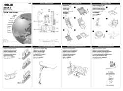
Step 3
Step 7
Step 4
Step 6
Step 1
Step 2
Step 5
Step 7
Step 2
Step 1: Install the CPU
APUを設置する
APU 설치
5
1
2
4
3
A
Installer le APU
Installieren der APU
Installare la APU
Instalar la APU
Установка процессора
APU’yu takın
Step 2: Install the fan
Installer le ventilateur de CPU
Installieren des CPU-Lüfters
Installare la ventola della CPU
Instalar el ventilador de la CPU
Установка вентилятора
CPU fanını takın
CPUファン を設置する
CPU 팬 설치
1
2
4
3
5
Step 3: Install the memory modules
Installer les modules mémoire
Installieren der Speichermodule
Installare i moduli di memoria
Instalar los módulos de memoria
Установка модулей памяти
Bellek modüllerini takın
メモリーモジュールを設置する
메모리 모듈 설치
Step 6: Connect the System Panel
PIN 1
PWR_BTN
PLED+ PLED- PWR GND
HD_LED+ HD_LED-
Ground
HWRST#
(NC)
F_PANEL
+PWR_LED-
+HDD_LED- RESET
Installer les connecteurs système
Installieren des Systemtafelanschlusses
Installare i connettori del pannello del sistema
Instalar conectores del panel del sistema
Установка соединений системной панели
Sistem paneli konnektörlerini takın
システムパネルコネクターを取り付ける
시스템 패널 커넥터 설치
Step 5: Install the PCI expansions cards
Installer une carte d’extension
Installieren der Erweiterungskarte(n)
Installare le schede di espansione
Instalar tarjetas de expansión
Установка карт расширения
Genişletme kartlarını takın
拡張カードを設置する
확장 카드 설치
Step 4: Install the SATA Hard Drives
Installer des périphériques SATA
Installieren der SATA-Geräte
Installare i dispositivi SATA
Instalar dispositivos SATA
Установка SATA устройств
SATA aygıtlarını takın
SATA デバイスを取り付ける
SATA 장치 설치
English
日本語
簡體中文
Deutsh
Français
Español
Русский
한국어
Türkçe
Italiano
Quick Start Guide
First Edition
February 2013
Copyright © 2013 ASUSTeK Computer Inc.
All Rights Reserved
Q8088
H61M-K
Motherboards
*This motherboard supports processors of up to 77W.
**Refer to http://www.asus.com for Intel
®
CPU support list.
-
manualzz.com
- Computers & electronics
- Computer components
- System components
- Motherboards
Инструкции и Руководства для Asus H61M-K.
Мы нашли 2
инструкции доступные для бесплатного скачивания:
Инструкция по началу работы, Руководство пользователя
Asus H61M-K Motherboard Quick Start Guide
Бренд:
Asus
Категория:
Motherboards
Размер:
1 MB
Страниц:
2
Язык(и):
Английский, Эстонский, Французский, Корейский, Польский, Турецкий
Открыть в новой вкладке

Asus H61M-C Specifications
Бренд:
Asus
Категория:
Motherboards
Размер:
3 MB
Страниц:
82
Язык(и):
Английский
Открыть в новой вкладке
На чтение 12 мин Просмотров 5 Опубликовано 11 апреля 2023 Обновлено 11 апреля 2023
Содержание
- Схема подключения разъёмов передней панели компьютера (F_PANEL, F_AUDIO и F_USB)
- КАК ПОДКЛЮЧИТЬ МАТЕРИНСКУЮ ПЛАТУ К ПЕРЕДНЕЙ ПАНЕЛИ КОРПУСА
- Как подключить кнопки к материнской плате asus
- Условные обозначения разъемов кнопок и индикаторов
- Подключаем кнопки корпуса к материнской плате
- Подготовка к подключению
- Подключение интерфейса передней панели
- Особенности подключения на платах Asus и Gigabyte (видео)
Схема подключения разъёмов передней панели компьютера (F_PANEL, F_AUDIO и F_USB)
Автор статьи: Шилин Алексей
Всем привет! В этой статье я наглядно покажу как правильно подключать кнопки (POWER, RESET) и устройства передней панели (F_PANEL, F_AUDIO и F_USB). Дело не хитрое, но стоит Вашего внимания.
В начале пару советов:
Разберу наглядно данное дело на старенькой материнской плате от фирмы Gigabyte модель GA-945GCM-S2C. Сразу скажу — Схемы подключения рисовал исключительно для данной статьи и на конкретном примере, цвета проводов у Вас будут отличаться. Главное понять и смысл подключения и воплотить (проверить) на своём ПК.

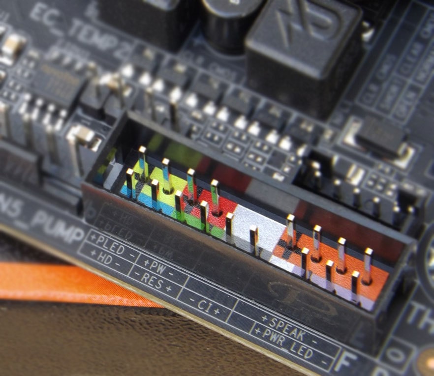
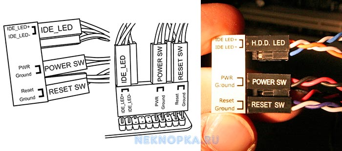
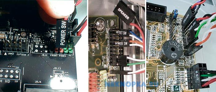
На этой картинке отображены разъёмы материнской платы для подключения коннекторов.
В основном (бывают исключения) под разъёмами мелким шрифтом написаны порядок подключения коннекторов и полярность. В моём случае указано:
PWR_LED (три разъемчика) — индикация включенного компьютера;
+PW- (PWRSW) — кнопка включения питания ПК;
-RES+ (RESET) — кнопка для перезагрузки ПК;
+HD- (IDE_LED, HDD_LED) — светодиод обращения к жесткому диску;
+SPEAK- (SPEAKER) — тот самый сигнал(ы), который издаёт компьютер при включении, если обнаружена ошибка.
Коннекторы выглядят так (см. скрины)

К каждому коннектрору подходят два провода:
В данном случае белые это минус «-» или Ground (земля) , а цветные «+». У коннектора SPEAKER (черный, красный) — чёрный «+», а красный «-«. Чтобы определить полярность коннекторов, достаточно его перевернуть на тыльную сторону — видим на против одного проводка маленький чёрный треугольник — это «+».
Переходим к следующему этапу, подключение передних дополнительных USB — разъёмов и картридера в разъёмы F_USB2 и F_USB1 (разницы нет, но лучше начинать по порядку). Если уже коннектор «спаянный», т.е. все проводки собраны в одну колодку — процесс значительно упрощается.
Просто подключаем этот «большой» коннектор состоящий из: восьми проводков, одного пустого и одного запаянного разъёма (всего десять) таким образом, чтобы ПУСТОЙ разъемчик совпал с ЗАПАЯННЫМ гнездом в коннекторе. (см. скрины)

А, вот если у Вас пучок проводов как на картинке — нарисую наглядную схемку:)

Здесь мы видим: POWER (Питание — 2 шт.), GND (Ground — «земля» 2шт.), D3+ (плюс), D3- (минус) на один порт usb и D2+ (плюс), D2- (минус) на другой порт. Как Вы уже догадались, два коннектора POWER идентичны и их можно менять местами между собой, так же как и GND. Главное не перепутать местами POWER и GND.

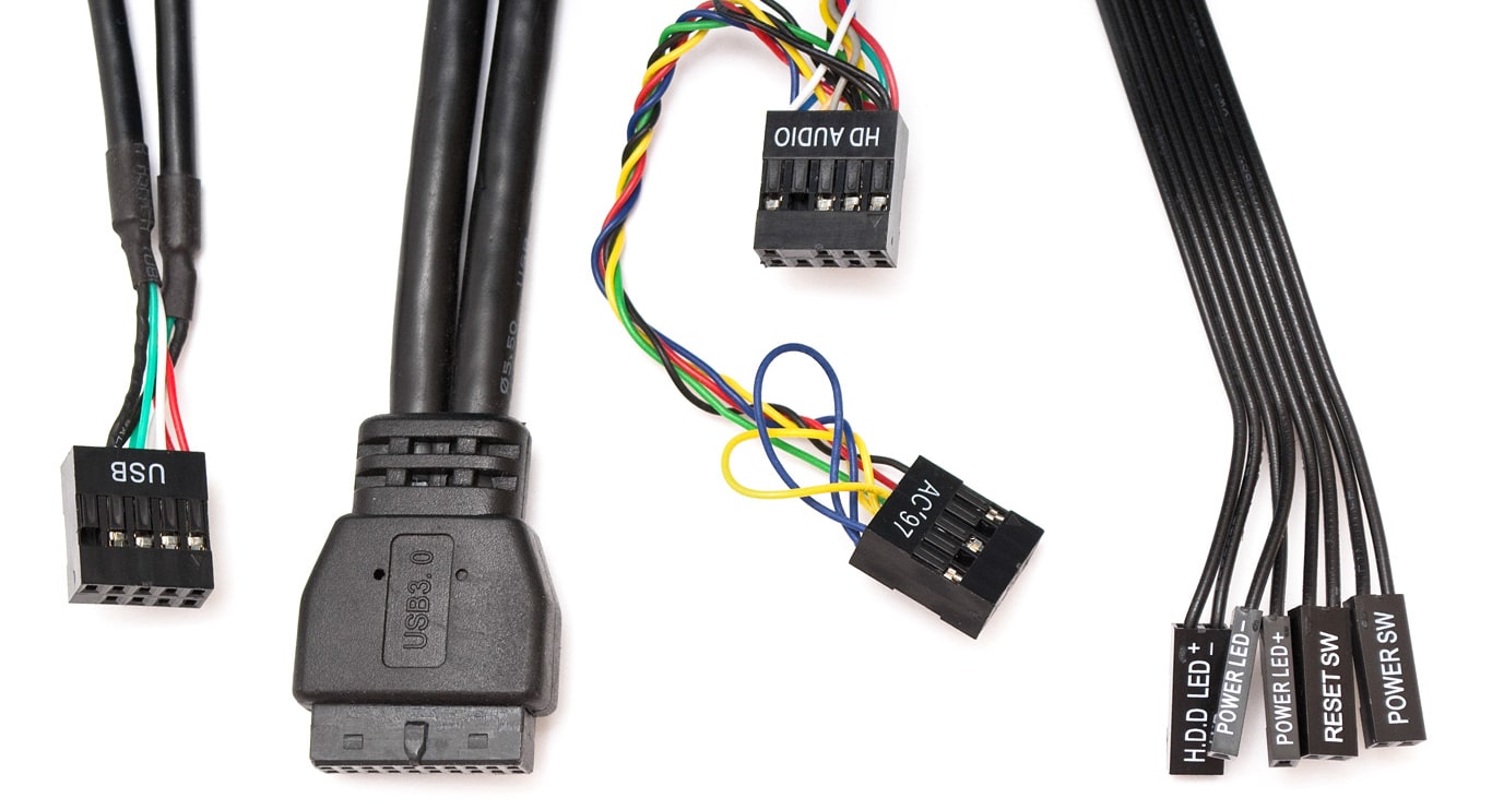
Так теперь осталось разобраться с подключением F_AUDIO разъемов для микрофона и наушников.
Опять же, если Вам повезло и от передней панели идёт большая колодка с 10-ью гнездами, просто вставляем (тут точно не ошибетесь). У меня случай поинтереснее. ) А, именно такие коннекторы: SPK R (выход правого канала на переднюю панель), SPK L (выход левого канала на переднюю панель), MIC (выход микрофона на переднюю панель) и GND.


Вот и всё подключено. Спасибо за внимание, удачи.
Если у Вас отличаются провода, названия коннекторов (колодок) и тд. и тп. не ленитесь, скачайте с официального сайта производителя Вашей материнской платы мануал (руководство) и там 99% найдёте схемы подключения всех F_PANEL, F_AUDIO и F_USB.
Черный экран windows 7 — Узнайте как избавиться от черного экрана Windows 7.
Восстановление windows 7 — Как произвести восстановление системы Windows 7.
Как активировать windows 7 — Как легально активировать windows 7.
Источник
КАК ПОДКЛЮЧИТЬ МАТЕРИНСКУЮ ПЛАТУ К ПЕРЕДНЕЙ ПАНЕЛИ КОРПУСА
Собираете свой первый PC самостоятельно и не знаете как подключить переднюю панель корпуса к материнской плате, то в данной статье мы постараемся максимально просто донести информацию о подключении передней панели, USB портов, вентиляторов (установленных в корпусе) к материнкой плате.
— КАК ПОДКЛЮЧИТЬ МАТЕРИНСКУЮ ПЛАТУ К ПЕРЕДНЕЙ ПАНЕЛИ —
1. Желательно заглянуть в (инструкцию) мануал от материнской платы и посмотреть подключение пинов к материнской плате.
2. Если под рукой его не оказалось или просто лень, можно зайти на сайт производителя и вбить модель материнской платы в поиск – там вы найдете мануал в электронном виде.
3. Если и на это нет времени и желания, просто следуйте указаниям, и у Вас всё получится!
— КОГДА НЕТ МАНУАЛА ПОД РУКОЙ —
(пользуемся указаниями на самой материнке)
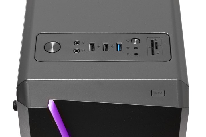
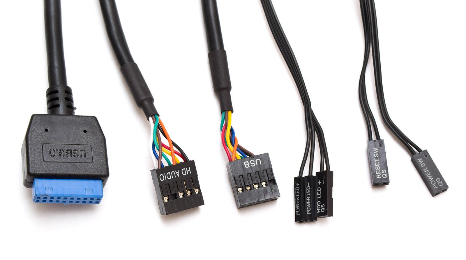
На корпусе есть кнопка включения, кнопка перезагрузки, разъемы USB, «Jack 3.5» для наушников и микрофона , подсветка и предустановленные кулера — всё это нужно подключить к материнской плате. Все кабели имеют свою маркировку (надпись).
Ранее все стандартные провода от корпуса шли ц в е т н ы е , это чуть-чуть упрощало задачу подключения.
Сейчас все кабеля идут чёрного цвета.
На всех материнских платах коннекторы подключения находятся в правом нижнем углу,
каждый разъём подписан, выше или ниже предпологаемого
месторасположения подключения.
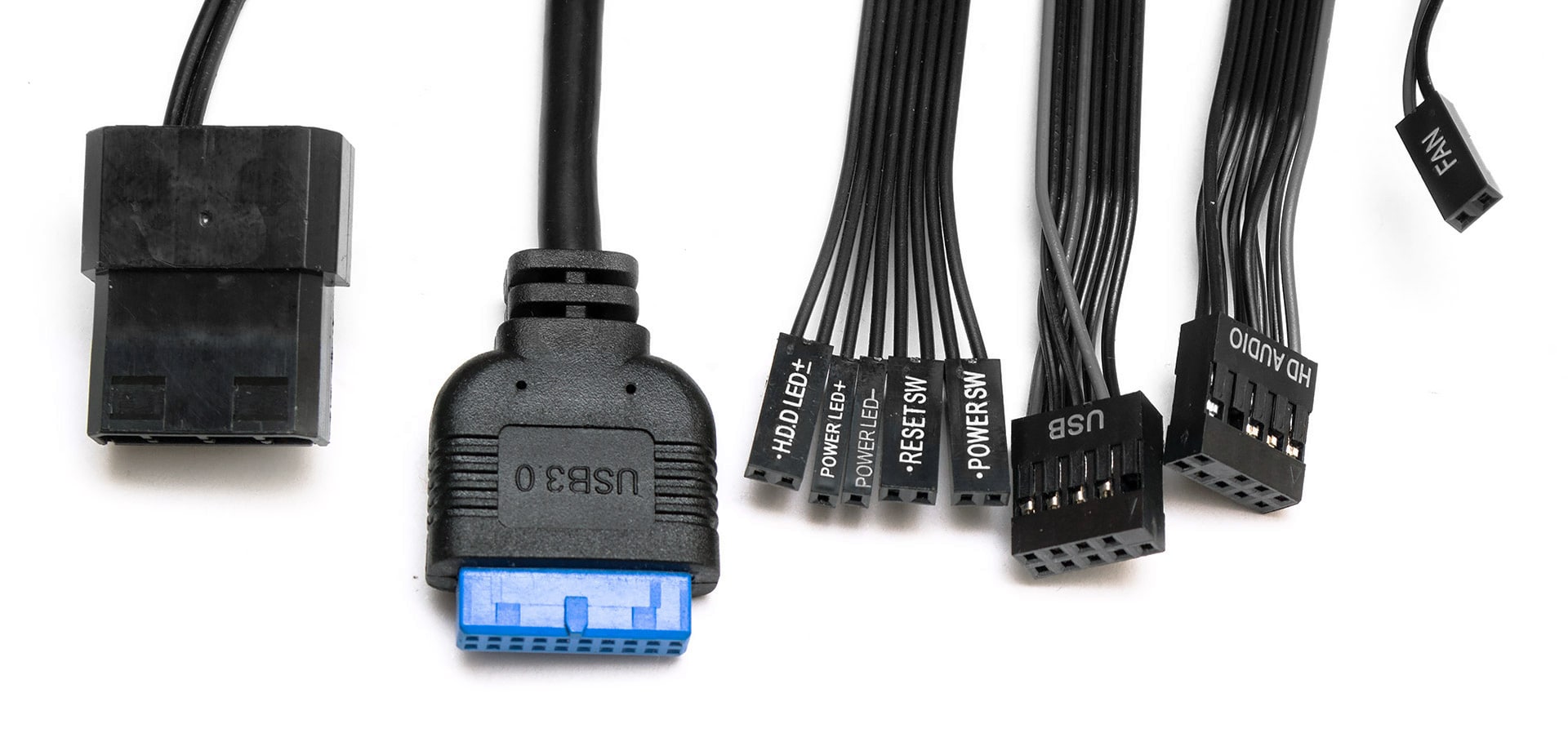
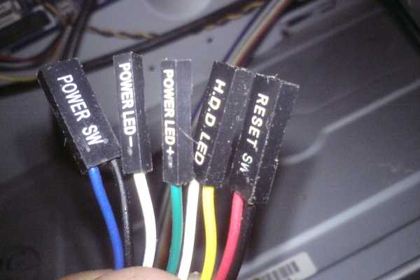
Переходим к самому подключению, берём кабель в руку (я рекомендую следующую последовательность подключения):
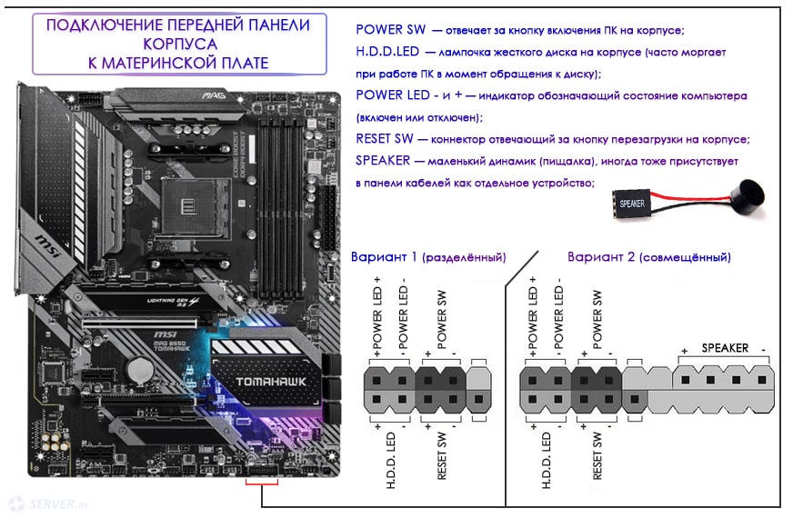
- RESET SW
- H.D.D. LED
- POWER SW
- POWER LED —
- POWER LED +
- SPEAKER — если необходим
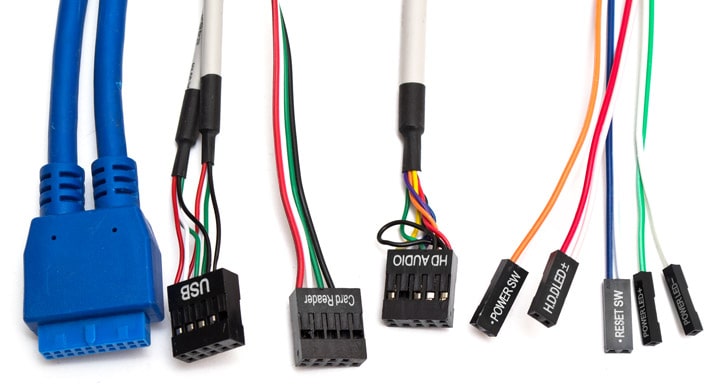
Остаются ещё не подключёнными провода (слева направо): 
- MOLEX — кабель питания, он будет если в корпусе установлены передние кулера (до 3-х штук)
- USB 3.0 и USB — кабель для питания двух разъёмов на передней панели
- HD AUDIO — кабель который позволяет использовать передние разъёмы для наушников и микрафона
- SATA — кабель питания подсветки корпуса
— БОНУСОМ РАЗБЕРЁМ КУДА И ЧТО ПОДКЛЮЧАТЬ —
Product: MSI MAG Z490 TOMAHAWK / БЛОК ПИТАНИЯ 600W
Manufacturer: MSI / Chieftec
Источник
Как подключить кнопки к материнской плате asus
Если Вы не знаете, как подключить переднюю панель корпуса к материнской плате, то в данной статье Вы найдете всю информацию о подключении кнопок питания и перезагрузки компьютера, индикатора обращения к HDD, USB-разъемы и т.д.
КАК ПОДКЛЮЧИТЬ МАТЕРИНСКУЮ ПЛАТУ К ПЕРЕДНЕЙ ПАНЕЛИ
Самый верный способ – подсмотреть подключение в инструкции к материнской плате (мануал). Если под рукой его не оказалось, можно зайти на сайт производителя и вбить модель материнской платы в поиск – там вы найдете мануал в электронном виде. Строго следуйте этим указаниям, и у Вас всё получится. Не стоит переживать, если Вы подключите что-то не так – в худшем случае разъемы и кнопки передней панели корпуса не будут работать, пока Вы их не подключите правильно.
КОГДА НЕТ МАНУАЛА ПОД РУКОЙ
Кнопки включения и перезагрузки, разъемы для флешек и других USB-устройств, наушников и микрофона, расположенные на передней панели корпуса, подключаются к материнской плате проводами с 1-2 контактами (pin). Подключаются они в определенной последовательности к соответствующим разъемам материнской платы. Чаще всего, кабели и разъемы имеют различную маркировку, цвет, надписи.
МАРКИРОВКА КАБЕЛЕЙ И РАЗЪЕМОВ
Существует основные типы кабелей, подключаемых к материнской плате:
- PowerSW (PWR) – кнопка включения, имеет 2 pin, кабель красного, зеленого или белого цвета (реже чёрным или жёлтым)
- ResetSW – кнопка перезагрузки, имеет 2 pin, чаще всего жёлтого цвета
- PowerLED и PowerLED+ – индикатор питания, имеет всего 2 pin либо 3 pin, бывает разных цветов
- H.D.D LED – индикатор загрузки жёсткого диска, также имеет 2 pin. Кстати, этого кабеля может и не быть
USB и звуковые разъемы идут отдельными кабелями, и подключаются в отдельные разъемы материнской платы (JPF1, JPF2 и т.д.).
Ниже мы приведем таблицу, в которой вы найдете самые распространенные варианты подключения наиболее популярных брендов среди материнских плат ASUS, MSI и GYGABYTE
- ASUS H110M-R/C/SI
- MSI A320M PRO-VD Plus
- GYGABYTE Z370 HD3
Самостоятельная сборка персонального компьютера — это не только интересное занятие, сравнимое с игрой в конструктор, но и отличный способ сэкономить приличную сумму (в сервисном центре данная услуга стоит в среднем 10% от стоимости всех комплектующих).
Дополнительной наградой за аккуратность и последовательность действий при выполнении работы станет идеально работающий компьютер и чувство гордости за свои достижения.
Сборка системного блока начинается с подключения к материнской плате основных компонентов ПК (видеокарты, жесткого диска, процессора, блока питания и т.д.).
На этом этапе вопросы возникают крайне редко, поскольку все разъемы и штекеры сделаны таким образом, что перепутать что-то местами или подключить не той стороной просто не получится.
Когда все «железо» скомпоновано, предстоит соединить с материнской платой сам корпус системного блока. На него выведены важные элементы управления и контрольные индикаторы.
Речь идет о кнопках включения питания (Power) и принудительной перезагрузки ПК (Reset), а также об индикаторах питания и работы жесткого диска.
От каждого из перечисленных элементов отходят провода с миниатюрными разъемами. Их необходимо надеть на соответствующие штекеры на материнской плате.
Условные обозначения разъемов кнопок и индикаторов
Чтобы было понятно, за выполнение какой функции отвечает конкретный провод, производители наносят на каждый мини-разъем следующие условные обозначения:
- Power SW (Power Switch) — разъем, который идет от кнопки питания (Power). Нажатием на эту кнопку запускается компьютер;
- Reset SW (Reset Switch) — разъем, идущий от кнопки принудительной перезагрузки компьютера;
- Power Led — коннектор индикатора включения/выключения ПК;
- HDD Led — провод, идущий от индикатора состояния жесткого диска ПК;
- SPEAKER — разъем для подключения системного динамика («пищалки»);
- HD Audio — микрофон и наушники;
- USB — коннектор USB-разъема.
Подключаем кнопки корпуса к материнской плате
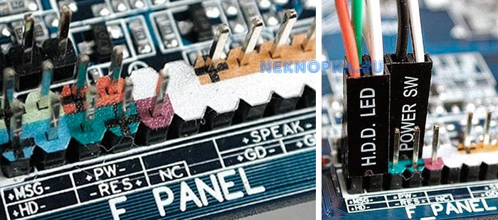
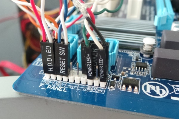
Для правильного подключения кнопок Power и Reset к материнской плате нужно иметь под рукой инструкцию. На схеме платы необходимо найти информацию о месте расположения блока контактов.
В большинстве случаев производители обозначают его как «F_Panel», «Front Panel» или просто «Panel». Если инструкция затерялась, нужно просто внимательно осмотреть материнскую плату и отыскать на ней данную группу разъемов.
- Сначала подключаем к плате разъем кнопки включения питания Power SW (Power Switch). Место для него на материнской плате обозначено как «PWR_BTN». Поскольку это кнопка, а не индикатор, то полярность подключения кнопки питания к материнской плате значения не имеет. Шлейф кнопки питания можно подсоединить любой стороной.
- Далее подключаем кнопку принудительной перезагрузки Reset SW (Reset Switch). Место для данного разъема на материнской плате обозначено как «Reset» или «RESET_SW», оно расположено непосредственно под коннектором кнопки питания. В данном случае полярность также значения не имеет.
- Подключаем индикаторы системного блока к материнской плате
- Ориентируясь на схему из инструкции или условные обозначения, нанесенные на материнскую плату, необходимо подключить коннекторы индикации.
При подключении индикаторов важно соблюдать полярность, поскольку в противном случае они попросту не будут гореть. На самой плате указана полярность символами «+» и «-«.
Она также должна присутствовать и на разъемах. Если ее нет или не видно, то следует воспользоваться подсказкой: белый провод — это минус, цветной — плюс.
Место для коннектора индикатора включения/выключения ПК (Power Led ) на материнской плате обозначено как «PWR_LED» , для подключения разъема HDD Led — «HDD_LED» .
ВИДЕО ИНСТРУКЦИЯ
» alt=»»>
Если после запуска компьютера какой-то из индикаторов не будет работать, достаточно просто переподключите коннектор, развернув его другой стороной.
Аналогичным образом к материнской плате подключаются и другие разъемы, идущие от корпуса системного блока — SPEAKER, HD Audio и USB.
Самостоятельная сборка своего персонального компьютера иногда может затянуться на весьма длительное время. Если с подключением основных устройств к ПК все достаточно просто и понятно, то подключение материнской платы и кнопок или индикации может показаться весьма сложным процессом. Ниже мы рассмотрим все основные нюансы подключения данного узла к материнской плате.
Подготовка к подключению
Предлагаем Вам ознакомиться с перечнем основных подготовительных этапов, которые значительно упростят процедуру подсоединения клавиш запуска и перезагрузки компьютера к его основной плате:
- ознакомление с инструкцией к материнской плате (если у Вас нет печатного варианта документации, то ее можно скачать в электронном формате на официальном сайте производителя);
- необходимо найти провода, которые подключены к коннекторам (эти провода помещены в переднем отсеке системного блока, а на их концах находятся черные пластмассовые соединители);
на материнской плате нужно отыскать посадочное место под коннекторы, которое называется портом и представляет собой набор штырьков – пинов (расположение порта зависит от особенностей самой платы, но его типичное местонахождение – это нижний угол «материнки»).
Подключение интерфейса передней панели
Если Вы внимательно изучили компоновку материнской платы своего компьютера, а также нашли все необходимые соединители и порты, то настало время сопоставить их между собой. Начать эту процедуру следует с коннекторов, которые отвечают за включение и перезагрузку системы. На их корпусах нанесены надписи «POWERSW» и «RESTARTSW» соответственно. Соединяем данные коннекторы со штырьками, возле которых присутствуют следующие обозначения: «PWRBTN»и «RESET».
Далее подключаем индикаторы работы компьютера. Необходимо найти соединитель «PLED –» и воткнуть его в соответствующий пин на плате. Коннектор, который подписан как «PLED +», подключаем рядом с предыдущим.
Индикатор, отображающий работу HDD, имеет разъем с подписью «HDDLED». Его необходимо воткнуть в штепсель «HDLED –».
Особенности подключения на платах Asus и Gigabyte (видео)
В предоставленном видеоролике очень наглядно показан процесс подключения к материнской плате кнопок питания и перезагрузки системы (на примере плат от таких производителей, как ASUS и GIGABYTE).
Источник