Руководства пользователя
Версия T4204
1.97 MB
Motherboard Installation Guide (Traditional Chinese)
Версия C4204
1.83 MB
Motherboard Installation Guide (Simplified Chinese)
Версия QJ4204
1.68 MB
Motherboard Installation Guide (Japanese)
Версия QG4204
1.6 MB
Motherboard Installation Guide (German)
Версия QF4204
1.59 MB
Motherboard Installation Guide (French)
Версия Q4204
43.39 MB
Motherboard Installation Guide (Multiple Languages)
Версия T2727
2.98 MB
P5LD2-VM SE User’s Manual for Traditional Chinese Edtion(t2727)
Версия T2679
2.99 MB
P5LD2-VM SE User»s Manual for Traditional Chinese Edtion(t2679)
Версия C2679
2.79 MB
P5LD2-VM SE User»s Manual for Simplified Chinese Edtion (c2679)
Версия E2679
3.93 MB
P5LD2-VM SE English Edition User’s Manual(E2679)
Версия G2679
1.8 MB
P5LD2-VM SE User’s Manual for German Edtion(G2679)
Версия F2679
6.11 MB
P5LD2-VM SE User’s Manual for French Edtion(F2679)
Версия T2437
2.57 MB
Motherboard DIY Troubleshooting Guide (Traditional Chinese version)
-
Драйверы
15
-
Инструкции по эксплуатации
10
Языки:

ASUS P5LD2-VM SE инструкция по эксплуатации
(90 страниц)
- Языки:Английский
-
Тип:
PDF -
Размер:
3.93 MB -
Описание:
P5LD2-VM SE English Edition User’s Manual(E2679)
Просмотр

ASUS P5LD2-VM SE инструкция по эксплуатации
(40 страниц)
- Языки:Молдавский, Немецкий
-
Тип:
PDF -
Размер:
1.65 MB -
Описание:
Motherboard Installation Guide (German)
Motherboard Installation Guide (German)
Просмотр

ASUS P5LD2-VM SE инструкция по эксплуатации
(90 страниц)
- Языки:Французский
-
Тип:
PDF -
Размер:
6.11 MB -
Описание:
P5LD2-VM SE User’s Manual for French Edtion(F2679)
Просмотр

ASUS P5LD2-VM SE инструкция по эксплуатации
(88 страниц)
- Языки:Китайский
-
Тип:
PDF -
Размер:
2.99 MB -
Описание:
P5LD2-VM SE User»s Manual for Traditional Chinese Edtion(t2679)
Просмотр

ASUS P5LD2-VM SE инструкция по эксплуатации
(44 страницы)
- Языки:Китайский, Молдавский
-
Тип:
PDF -
Размер:
1.88 MB -
Описание:
Motherboard Installation Guide (Simplified Chinese)
Просмотр

ASUS P5LD2-VM SE инструкция по эксплуатации
(44 страницы)
- Языки:Китайский, Молдавский
-
Тип:
PDF -
Размер:
2.02 MB -
Описание:
Motherboard Installation Guide (Traditional Chinese)
Просмотр

ASUS P5LD2-VM SE инструкция по эксплуатации
(8 страниц)
- Языки:Китайский, Молдавский
-
Тип:
PDF -
Размер:
2.67 MB -
Описание:
Motherboard DIY Troubleshooting Guide (Traditional Chinese version)
Просмотр

ASUS P5LD2-VM SE инструкция по эксплуатации
(40 страниц)
- Языки:Молдавский, Японский
-
Тип:
PDF -
Размер:
1.73 MB -
Описание:
Motherboard Installation Guide (Japanese)
Просмотр

ASUS P5LD2-VM SE инструкция по эксплуатации
(40 страниц)
- Языки:Молдавский, Французский
-
Тип:
PDF -
Размер:
1.64 MB -
Описание:
Motherboard Installation Guide (French)
Просмотр

ASUS P5LD2-VM SE инструкция по эксплуатации
(721 страница)
- Языки:Молдавский
-
Тип:
PDF -
Размер:
43.88 MB -
Описание:
Motherboard Installation Guide (Multiple Languages)
Просмотр
На NoDevice можно скачать инструкцию по эксплуатации для ASUS P5LD2-VM SE. Руководство пользователя необходимо для ознакомления с правилами установки и эксплуатации ASUS P5LD2-VM SE. Инструкции по использованию помогут правильно настроить ASUS P5LD2-VM SE, исправить ошибки и выявить неполадки.
- Manuals
- Brands
- Asus Manuals
- Motherboard
- Motherboard P5LD2-VM DH
- User manual
-
Contents
-
Table of Contents
-
Bookmarks
Quick Links
Related Manuals for Asus P5LD2-VM
Summary of Contents for Asus P5LD2-VM
-
Page 1
P5LD2-VM… -
Page 2
Product warranty or service will not be extended if: (1) the product is repaired, modified or altered, unless such repair, modification of alteration is authorized in writing by ASUS; or (2) the serial number of the product is defaced or missing. -
Page 3: Table Of Contents
Welcome! …………….1-2 Package contents …………..1-2 Special features …………..1-2 1.3.1 Product highlights ……….. 1-2 1.3.2 Innovative ASUS features ……..1-4 Before you proceed ………….. 1-5 Motherboard overview …………1-6 1.5.1 Placement direction ……….1-6 1.5.2 Screw holes …………1-6 1.5.3…
-
Page 4
Creating a bootable floppy disk ……2-2 2.1.2 ASUS EZ Flash utility ……….2-3 2.1.3 AFUDOS utility …………2-4 2.1.4 ASUS CrashFree BIOS 2 utility …….. 2-6 2.1.5 ASUS Update utility ……….2-8 BIOS setup program …………2-11 2.2.1 BIOS menu screen ……….2-12 2.2.2… -
Page 5
Running the support CD ……… 3-2 3.2.2 Drivers menu …………3-3 3.2.3 Utilities menu …………3-4 3.2.4 Manuals menu …………3-5 3.2.5 ASUS Contact information ……..3-6 Appendix: CPU features Appendix: CPU features Appendix: CPU features Appendix: CPU features Appendix: CPU features Intel ®… -
Page 6: Notices
Notices Federal Communications Commission Statement Federal Communications Commission Statement Federal Communications Commission Statement Federal Communications Commission Statement Federal Communications Commission Statement This device complies with Part 15 of the FCC Rules. Operation is subject to the following two conditions: • This device may not cause harmful interference, and •…
-
Page 7: Safety Information
Safety information Electrical safety Electrical safety Electrical safety Electrical safety Electrical safety • To prevent electrical shock hazard, disconnect the power cable from the electrical outlet before relocating the system. • When adding or removing devices to or from the system, ensure that the power cables for the devices are unplugged before the signal cables are connected.
-
Page 8: About This Guide
A S U S w e b s i t e s A S U S w e b s i t e s The ASUS website provides updated information on ASUS hardware and software products. Refer to the ASUS contact information.
-
Page 9: Typography
Conventions used in this guide Conventions used in this guide Conventions used in this guide Conventions used in this guide Conventions used in this guide To make sure that you perform certain tasks properly, take note of the following symbols used throughout this manual. D A N G E R / W A R N I N G : D A N G E R / W A R N I N G : D A N G E R / W A R N I N G :…
-
Page 10: P5Ld2-Vm Specifications Summary
P5LD2-VM specifications summary C P U C P U C P U C P U C P U LGA775 socket for Intel ® Pentium ® D/Intel ® Pentium ® or Intel ® Celeron ® processors Compatible with Intel ® PCG 05B/05A and 04B/04A processors Supports Intel ®…
-
Page 11
B I O S f e a t u r e s 4 Mb Flash ROM, AMI BIOS, PnP, WfM2.0, DMI2.0, SM BIOS 2.3, ASUS EZ Flash, CrashFree BIOS2, C.P.R. (CPU Parameter Recall) S p e c i a l f e a t u r e s… -
Page 12
x i i x i i x i i x i i x i i… -
Page 13: Chapter 1: Product Introduction
This chapter describes the motherboard features and the new technologies it supports. Product introduction A S U S P 5 L D 2 — V M A S U S P 5 L D 2 — V M A S U S P 5 L D 2 — V M 1 — 1 1 — 1 1 — 1…
-
Page 14: Welcome
P 5 L D 2 — V M m o t h e r b o a r d ! The motherboard delivers a host of new features and latest technologies, making it another standout in the long line of ASUS quality motherboards! Before you start installing the motherboard, and hardware devices on it, check the items in your package with the list below.
-
Page 15
Intel Intel ® ® ® ® ® 945G chipset 945G chipset Intel Intel Intel 945G chipset 945G chipset 945G chipset The Intel ® 945G graphics memory controller hub (GMCH) and the ICH7 I/O controller hub provide the vital interfaces for the motherboard. The GMCH features the Intel ®… -
Page 16: Innovative Asus Features
ASUS EZ Flash BIOS ASUS EZ Flash BIOS With the ASUS EZ Flash, you can easily update the system BIOS even before loading the operating system. No need to use a DOS-based utility or boot from a floppy disk. See page 2-3 for details.
-
Page 17: Before You Proceed
Before you proceed Take note of the following precautions before you install motherboard components or change any motherboard settings. • Unplug the power cord from the wall socket before touching any component. • Use a grounded wrist strap or touch a safely grounded object or to a metal object, such as the power supply case, before handling components to avoid damaging them due to static electricity •…
-
Page 18: Motherboard Overview
Motherboard overview Before you install the motherboard, study the configuration of your chassis to ensure that the motherboard fits into it. Make sure to unplug the power cord before installing or removing the motherboard. Failure to do so can cause you physical injury and damage motherboard components.
-
Page 19: Motherboard Layout
1.5.3 1.5.3 1.5.3 1.5.3 1.5.3 Motherboard layout Motherboard layout Motherboard layout Motherboard layout Motherboard layout CPU_FAN PS/2KBMS T: Mouse B: Keyboard COM1 ATX12V LGA775 VGA1 F_USB12 LAN_USB34 ® Intel Top:Rear Speaker Out GMCH Center: Side Speaker Out 945G Below: Center/Subwoofer Top:Line In Center:Line Out CHA_FAN…
-
Page 20: Central Processing Unit (Cpu)
Contact your retailer immediately if the PnP cap is missing, or if you see any damage to the PnP cap/socket pins/motherboard components. ASUS will shoulder the cost of repair only if the damage is shipment/ transit-related. •…
-
Page 21
Press the load lever with your thumb (A) and move it to the left (B) until it is released from the retention tab. P n P C a p P n P C a p P n P C a p P n P C a p P n P C a p R e t e n t i o n t a b… -
Page 22
Close the load plate (A), then push the load lever (B) until it snaps into the retention tab. The CPU fits in only one correct orientation. DO NOT force the CPU into the socket to prevent bending the connectors on the socket and damaging the CPU! The motherboard supports Intel ®… -
Page 23: Installling The Cpu Heatsink And Fan
1.6.2 1.6.2 1.6.2 Installling the CPU heatsink and fan Installling the CPU heatsink and fan Installling the CPU heatsink and fan 1.6.2 1.6.2 Installling the CPU heatsink and fan Installling the CPU heatsink and fan The Intel ® Pentium ® 4 LGA775 processor requires a specially designed heatsink and fan assembly to ensure optimum thermal condition and performance.
-
Page 24
Push down two fasteners at a time in a diagonal sequence to secure the heatsink and fan assembly in place. When the fan and heatsink assembly is in place, connect the CPU fan cable to the connector on the motherboard labeled CPU_FAN. CPU_FAN CPU FAN PWM CPU FAN IN… -
Page 25: Uninstalling The Cpu Heatsink And Fan
1.6.3 1.6.3 1.6.3 Uninstalling the CPU heatsink and fan Uninstalling the CPU heatsink and fan Uninstalling the CPU heatsink and fan 1.6.3 1.6.3 Uninstalling the CPU heatsink and fan Uninstalling the CPU heatsink and fan To uninstall the CPU heatsink and fan: Disconnect the CPU fan cable from the connector on the motherboard.
-
Page 26
Remove the heatsink and fan assembly from the motherboard. Rotate each fastener clockwise to reset the orientation. N a r r o w e n d o f t h e g r o o v e N a r r o w e n d o f t h e g r o o v e N a r r o w e n d o f t h e g r o o v e N a r r o w e n d o f t h e g r o o v e N a r r o w e n d o f t h e g r o o v e… -
Page 27: System Memory
System memory 1.7.1 1.7.1 1.7.1 1.7.1 1.7.1 Overview Overview Overview Overview Overview The motherboard comes with four Double Data Rate 2 (DDR2) Dual Inline Memory Modules (DIMM) sockets. A DDR2 module has the same physical dimensions as a DDR DIMM but has a 240-pin footprint compared to the 184-pin DDR DIMM.
-
Page 28: Ddr2 Qualified Vendors List
DDR2 Qualified Vendors List The following table lists the memory modules that have been tested and qualified for use with this motherboard. Visit the ASUS website (www.asus.com) for the latest DDR2 DIMM modules for this motherboard. DDR2 533 Qualified Vendors List…
-
Page 29: Installing A Dimm
1.7.4 1.7.4 1.7.4 1.7.4 1.7.4 Installing a DIMM Installing a DIMM Installing a DIMM Installing a DIMM Installing a DIMM Unplug the power supply before adding or removing DIMMs or other system components. Failure to do so can cause severe damage to both the motherboard and the components.
-
Page 30: Expansion Slots
Expansion slots In the future, you may need to install expansion cards. The following sub-sections describe the slots and the expansion cards that they support. Make sure to unplug the power cord before adding or removing expansion cards. Failure to do so may cause you physical injury and damage motherboard components.
-
Page 31: Interrupt Assignments
1.8.3 1.8.3 1.8.3 1.8.3 1.8.3 Interrupt assignments Interrupt assignments Interrupt assignments Interrupt assignments Interrupt assignments Standard interrupt assignments Standard interrupt assignments Standard interrupt assignments Standard interrupt assignments Standard interrupt assignments I R Q I R Q I R Q S t a n d a r d F u n c t i o n S t a n d a r d F u n c t i o n S t a n d a r d F u n c t i o n I R Q…
-
Page 32: Pci Slots
1.8.4 1.8.4 PCI slots PCI slots 1.8.5 1.8.5 PCI Express x16 PCI Express x16 1.8.4 1.8.4 1.8.4 PCI slots PCI slots PCI slots 1.8.5 1.8.5 1.8.5 PCI Express x16 PCI Express x16 PCI Express x16 The PCI slots support cards such as This motherboard supports one PCI a LAN card, SCSI card, USB card, Express x16 graphics card.
-
Page 33: Clear Rtc Ram
Jumpers 1 . 1 . C l e a r R T C R A M ( C L R T C ) C l e a r R T C R A M ( C L R T C ) C l e a r R T C R A M ( C L R T C ) C l e a r R T C R A M ( C L R T C ) C l e a r R T C R A M ( C L R T C )
-
Page 34: 1.10 Connectors
1.10 Connectors 1.10.1 1.10.1 Rear panel connectors Rear panel connectors 1.10.1 1.10.1 Rear panel connectors 1.10.1 Rear panel connectors Rear panel connectors 1 . 1 . P S / 2 m o u s e p o r t ( g r e e n ) . P S / 2 m o u s e p o r t ( g r e e n ) .
-
Page 35
8 . 8 . M i c r o p h o n e p o r t ( p i n k ) . M i c r o p h o n e p o r t ( p i n k ) . M i c r o p h o n e p o r t ( p i n k ) . -
Page 36: Internal Connectors
1.10.2 1.10.2 Internal connectors 1.10.2 Internal connectors Internal connectors Internal connectors 1.10.2 1.10.2 Internal connectors 1 . 1 . F l o p p y d i s k d r i v e c o n n e c t o r ( 3 4 — 1 p i n F L O P P Y ) F l o p p y d i s k d r i v e c o n n e c t o r ( 3 4 — 1 p i n F L O P P Y ) F l o p p y d i s k d r i v e c o n n e c t o r ( 3 4 — 1 p i n F L O P P Y ) F l o p p y d i s k d r i v e c o n n e c t o r ( 3 4 — 1 p i n F L O P P Y )
-
Page 37: Hard Disk Drives
3 . 3 . I T E I D E c o n n e c t o r ( 4 0 — 1 p i n P R I _ E I D E [ r e d ] ) I T E I D E c o n n e c t o r ( 4 0 — 1 p i n P R I _ E I D E [ r e d ] ) I T E I D E c o n n e c t o r ( 4 0 — 1 p i n P R I _ E I D E [ r e d ] ) I T E I D E c o n n e c t o r ( 4 0 — 1 p i n P R I _ E I D E [ r e d ] )
-
Page 38
5 . 5 . S p e a k e r c o n n e c t o r ( 4 — p i n S P E A K E R ) S p e a k e r c o n n e c t o r ( 4 — p i n S P E A K E R ) S p e a k e r c o n n e c t o r ( 4 — p i n S P E A K E R ) S p e a k e r c o n n e c t o r ( 4 — p i n S P E A K E R ) S p e a k e r c o n n e c t o r ( 4 — p i n S P E A K E R ) -
Page 39
7 . 7 . D i g i t a l A u d i o c o n n e c t o r ( 4 — 1 p i n S P D I F _ O U T ) D i g i t a l A u d i o c o n n e c t o r ( 4 — 1 p i n S P D I F _ O U T ) D i g i t a l A u d i o c o n n e c t o r ( 4 — 1 p i n S P D I F _ O U T ) D i g i t a l A u d i o c o n n e c t o r ( 4 — 1 p i n S P D I F _ O U T ) -
Page 40: Atx Power Connectors
9 . 9 . ATX power connectors ATX power connectors ATX power connectors ATX power connectors ATX power connectors (24-pin EATXPWR (24-pin EATXPWR a n d a n d 4-pin ATX12V) 4-pin ATX12V) (24-pin EATXPWR (24-pin EATXPWR (24-pin EATXPWR a n d a n d a n d 4-pin ATX12V) 4-pin ATX12V)
-
Page 41
1 0 . 1 0 . O p t i c a l d r i v e a u d i o c o n n e c t o r ( 4 — p i n C D ) 1 0 . -
Page 42: Front Panel Audio Connector
1 2 . 1 2 . 1 2 . F r o n t p a n e l a u d i o c o n n e c t o r ( 1 0 — 1 p i n A A F P ) F r o n t p a n e l a u d i o c o n n e c t o r ( 1 0 — 1 p i n A A F P ) F r o n t p a n e l a u d i o c o n n e c t o r ( 1 0 — 1 p i n A A F P ) F r o n t p a n e l a u d i o c o n n e c t o r ( 1 0 — 1 p i n A A F P )
-
Page 43
1 4 . 1 4 . 1 4 . S y s t e m p a n e l c o n n e c t o r ( 1 0 — 1 p i n F _ P A N E L ) 1 4 . -
Page 44
1 — 3 2 1 — 3 2 1 — 3 2 C h a p t e r 1 : P r o d u c t i n t r o d u c t i o n C h a p t e r 1 : P r o d u c t i n t r o d u c t i o n C h a p t e r 1 : P r o d u c t i n t r o d u c t i o n 1 — 3 2… -
Page 45: Chapter 2: Bios Setup
This chapter tells how to change the system settings through the BIOS Setup menus. Detailed descriptions of the BIOS parameters are also provided. BIOS setup A S U S P 5 L D 2 — V M A S U S P 5 L D 2 — V M A S U S P 5 L D 2 — V M 2 — 1 2 — 1…
-
Page 46: Managing And Updating Your Bios
Refer to the corresponding sections for details on these utilities. Save a copy of the original motherboard BIOS file to a bootable floppy disk in case you need to restore the BIOS in the future. Copy the original motherboard BIOS using the ASUS Update or AFUDOS utilities. 2.1.1 2.1.1 2.1.1…
-
Page 47: Asus Ez Flash Utility
ASUS EZ Flash utility ASUS EZ Flash utility The ASUS EZ Flash feature allows you to update the BIOS without having to go through the long process of booting from a floppy disk and using a DOS-based utility. The EZ Flash utility is built-in the BIOS chip so it is accessible by pressing <Alt>…
-
Page 48: Afudos Utility
2.1.3 2.1.3 2.1.3 AFUDOS utility AFUDOS utility AFUDOS utility 2.1.3 2.1.3 AFUDOS utility AFUDOS utility The AFUDOS utility allows you to update the BIOS file in DOS environment using a bootable floppy disk with the updated BIOS file. This utility also allows you to copy the current BIOS file that you can use as backup when the BIOS fails or gets corrupted during the updating process.
-
Page 49
Updating the BIOS file To update the BIOS file using the AFUDOS utility: Visit the ASUS website (www.asus.com) and download the latest BIOS file for the motherboard. Save the BIOS file to a bootable floppy disk. Write the BIOS filename on a piece of paper. You need to type the exact BIOS filename at the DOS prompt. -
Page 50: Asus Crashfree Bios 2 Utility
ASUS CrashFree BIOS 2 utility ASUS CrashFree BIOS 2 utility The ASUS CrashFree BIOS 2 is an auto recovery tool that allows you to restore the BIOS file when it fails or gets corrupted during the updating process. You can update a corrupted BIOS file using the motherboard support CD or the floppy disk that contains the updated BIOS file.
-
Page 51
Restart the system after the utility completes the updating process. The recovered BIOS may not be the latest BIOS version for this motherboard. Visit the ASUS website (www.asus.com) to download the latest BIOS file. A S U S P 5 L D 2 — V M… -
Page 52: Asus Update Utility
ASUS Update utility 2.1.5 2.1.5 ASUS Update utility ASUS Update utility The ASUS Update is a utility that allows you to manage, save, and update the motherboard BIOS in Windows ® environment. The ASUS Update utility allows you to: • Save the current BIOS file •…
-
Page 53
Updating the BIOS through the Internet Updating the BIOS through the Internet Updating the BIOS through the Internet To update the BIOS through the Internet: Launch the ASUS Update utility from the Windows ® desktop by clicking S t a r t… -
Page 54
A S U S U p d a t e A S U S U p d a t e. The ASUS Update main window appears. U p d a t e B I O S f r o m a… -
Page 55: Bios Setup Program
• Visit the ASUS website (www.asus.com) to download the latest BIOS file for this motherboard and . A S U S P 5 L D 2 — V M…
-
Page 56: Bios Menu Screen
2.2.1 2.2.1 2.2.1 BIOS menu screen BIOS menu screen BIOS menu screen 2.2.1 2.2.1 BIOS menu screen BIOS menu screen M e n u i t e m s M e n u i t e m s M e n u i t e m s M e n u i t e m s M e n u i t e m s M e n u b a r…
-
Page 57: Menu Items
For example, selecting M a i n M a i n M a i n shows the Primary IDE Master :[ST320413A] configure system time. Primary IDE Slave :[ASUS CD-S340] Secondary IDE Master :[Not Detected] Secondary IDE Slave :[Not Detected] Main menu items. Third IDE Master…
-
Page 58: Main Menu
Main menu When you enter the BIOS Setup program, the Main menu screen appears, giving you an overview of the basic system information. Refer to section “2.2.1 BIOS menu screen” for information on the menu screen items and how to navigate through them. Use [ENTER], [TAB] System Time [11:51:19]…
-
Page 59: Primary, Third And Fourth Ide Master/Slave
2.3.4 2.3.4 2.3.4 Primary, Third and Fourth IDE Master/Slave Primary, Third and Fourth IDE Master/Slave Primary, Third and Fourth IDE Master/Slave 2.3.4 2.3.4 Primary, Third and Fourth IDE Master/Slave Primary, Third and Fourth IDE Master/Slave While entering Setup, the BIOS automatically detects the presence of IDE devices.
-
Page 60: Ide Configuration
PIO Mode [Auto] PIO Mode [Auto] PIO Mode [Auto] PIO Mode [Auto] PIO Mode [Auto] Selects the PIO mode. Configuration options: [Auto] [0] [1] [2] [3] [4] DMA Mode [Auto] DMA Mode [Auto] DMA Mode [Auto] DMA Mode [Auto] DMA Mode [Auto] Selects the DMA mode.
-
Page 61
Enhanced Mode Support On [S-ATA] The default setting S-ATA allows you to use native OS on Serial ATA and Parallel ATA ports. We recommend that you do not change the default setting for better OS compatibility. In this setting, you may use legacy OS on the Parallel ATA ports o n l y i f o n l y i f o n l y i f… -
Page 62: System Information
2.3.6 2.3.6 2.3.6 System Information System Information System Information 2.3.6 2.3.6 System Information System Information This menu gives you an overview of the general system specifications. The BIOS automatically detects the items in this menu. AMIBIOS Version : 0128 Build Date : 05/11/05 Processor Type : Genuine Intel(R) CPU 3.20GHz…
-
Page 63: Advanced Menu
Advanced menu The Advanced menu items allow you to change the settings for the CPU and other system devices. Take caution when changing the settings of the Advanced menu items. Incorrect field values can cause the system to malfunction. Configure CPU. JumperFree Configuration USB Configuration CPU Configuration…
-
Page 64
A I O v e r c l o c k i n g A I O v e r c l o c k i n g The following item appears only when you set the A I O v e r c l o c k i n g A I O v e r c l o c k i n g A I O v e r c l o c k i n g item to [Manual]. -
Page 65
MCH Chipset Voltage [Auto] MCH Chipset Voltage [Auto] MCH Chipset Voltage [Auto] MCH Chipset Voltage [Auto] MCH Chipset Voltage [Auto] Allows you to select the memory controller hub (MCH) voltage. Configuration options: [Auto] [1.50V] [1.60V] [1.70V] CPU VCore Voltage [Auto] CPU VCore Voltage [Auto] CPU VCore Voltage [Auto] CPU VCore Voltage [Auto]… -
Page 66: Usb Configuration
2.4.2 2.4.2 2.4.2 2.4.2 2.4.2 USB Configuration USB Configuration USB Configuration USB Configuration USB Configuration The items in this menu allows you to change the USB-related features. Select an item then press <Enter> to display the configuration options. USB Configuration Module Version — 2.23.0-F.4 USB Devices Enabled: None USB Function…
-
Page 67: Cpu Configuration
2.4.3 2.4.3 2.4.3 CPU Configuration CPU Configuration CPU Configuration 2.4.3 2.4.3 CPU Configuration CPU Configuration The items in this menu show the CPU-related information that the BIOS automatically detects. Configure Advanced CPU settings Sets the ratio between CPU Core Clock and the Manufacturer: Intel FSB Frequency.
-
Page 68
Execute Disable Function [Disabled] Execute Disable Function [Disabled] Execute Disable Function [Disabled] Execute Disable Function [Disabled] Execute Disable Function [Disabled] Enables or disables the Execute Disable function. This item appears only when you install a processor with the Execute Disable function. Configuration options: [Disabled] [Enabled] Enhanced C1 Control [Auto] Enhanced C1 Control [Auto]… -
Page 69: Chipset
2.4.4 2.4.4 Chipset Chipset 2.4.4 2.4.4 2.4.4 Chipset Chipset Chipset The Chipset menu allows you to change the advanced chipset settings. Select an item then press <Enter> to display the sub-menu. Advanced Chipset Settings Configure DRAM Timing by SPD [Enabled] Booting Graphic Adapter Priori [PCI Express/Int-VG] Internal Graphics Mode Select [Enabled, 8MB]…
-
Page 70: Onboard Devices Configuration
Booting Graphic Adapter Priority [PCI Express/Int-VGA] Booting Graphic Adapter Priority [PCI Express/Int-VGA] Booting Graphic Adapter Priority [PCI Express/Int-VGA] Booting Graphic Adapter Priority [PCI Express/Int-VGA] Booting Graphic Adapter Priority [PCI Express/Int-VGA] Allows selection of the graphics controller to use as primary boot device. Configuration options: [Internal VGA] [PCI Express/Int-VGA] [PCI Express/PCI] [PCI/PCI Express] [PCI/Int-VGA] Internal Graphics Mode Select [Enabled, 8MB]…
-
Page 71
ITE8211F Controller [Enabled] ITE8211F Controller [Enabled] ITE8211F Controller [Enabled] ITE8211F Controller [Enabled] ITE8211F Controller [Enabled] Enables or disables the onboard ITE ® 8211F IDE controller. Configuration options: [Enabled] [Disabled] Detecting Device Time [Quick Mode] Sets the ITE8211F detecting device time. If the devices installed on the ITE IDE connector cannot be detected, set this item to Standard Mode to enable complete detecting process. -
Page 72: Pci Pnp
2.4.6 2.4.6 2.4.6 2.4.6 2.4.6 PCI PnP PCI PnP PCI PnP PCI PnP PCI PnP The PCI PnP menu items allow you to change the advanced settings for PCI/PnP devices. The menu includes setting IRQ and DMA channel resources for either PCI/PnP or legacy ISA devices, and setting the memory size block for legacy ISA devices.
-
Page 73: Power Menu
IRQ-xx assigned to [PCI Device] IRQ-xx assigned to [PCI Device] IRQ-xx assigned to [PCI Device] IRQ-xx assigned to [PCI Device] IRQ-xx assigned to [PCI Device] When set to [PCI Device], the specific IRQ is free for use of PCI/PnP devices. When set to [Reserved], the IRQ is reserved for legacy ISA devices.
-
Page 74: Apm Configuration
2.5.4 2.5.4 APM Configuration APM Configuration 2.5.4 2.5.4 2.5.4 APM Configuration APM Configuration APM Configuration APM Configuration Enabled or disable APM. Power Button Mode [On/Off] Restore on AC Power Loss [Power Off] Power On By RTC Alarm [Disabled] Power On By External Modems [Disabled] Power On By PCI Devices [Disabled]…
-
Page 75
Power On By PCI Devices [Disabled] Power On By PCI Devices [Disabled] Power On By PCI Devices [Disabled] Power On By PCI Devices [Disabled] Power On By PCI Devices [Disabled] When set to [Enabled], this parameter allows you to turn on the system through a PCI LAN or modem card. -
Page 76: Hardware Monitor
CPU Q-Fan Control [Disabled] CPU Q-Fan Control [Disabled] CPU Q-Fan Control [Disabled] Allows you to enable or disable the ASUS Q-Fan feature that smartly adjusts the fan speeds for more efficient system operation. Configuration options: [Disabled] [Enabled] The C P U F A N P R O F I L E M O D E…
-
Page 77
Chassis Fan Speed [xxxxRPM] or [N/A] Chassis Fan Speed [xxxxRPM] or [N/A] Chassis Fan Speed [xxxxRPM] or [N/A] Chassis Fan Speed [xxxxRPM] or [N/A] Chassis Fan Speed [xxxxRPM] or [N/A] The onboard hardware monitor automatically detects and displays the chassis fan speed in rotations per minute (RPM). If the fan is not connected to the chassis, the specific field shows N/A. -
Page 78: Boot Menu
[1st FLOPPY DRIVE] 2nd Boot Device [PM-ST330620A] 3rd Boot Device [PS-ASUS CD-S360] 1st ~ xxth Boot Device [1st Floppy Drive] 1st ~ xxth Boot Device [1st Floppy Drive] 1st ~ xxth Boot Device [1st Floppy Drive] 1st ~ xxth Boot Device [1st Floppy Drive]…
-
Page 79: Boot Settings Configuration
This allows you to enable or disable the full screen logo display feature. Configuration options: [Disabled] [Enabled] Set this item to [Enabled] to use the ASUS MyLogo2™ feature. Add On ROM Display Mode [Force BIOS] Add On ROM Display Mode [Force BIOS]…
-
Page 80: Security
Interrupt 19 Capture [Disabled] Interrupt 19 Capture [Disabled] Interrupt 19 Capture [Disabled] Interrupt 19 Capture [Disabled] Interrupt 19 Capture [Disabled] When set to [Enabled], this function allows the option ROMs to trap Interrupt 19. Configuration options: [Disabled] [Enabled] 2.6.3 2.6.3 2.6.3 Security Security…
-
Page 81
After you have set a supervisor password, the other items appear to allow you to change other security settings. Security Settings Supervisor Password : Not Installed User Password : Not Installed Change Supervisor Password User Access Level [Full Access] Change User Password Clear User Password Password Check [Setup]… -
Page 82: Exit Menu
Password Check [Setup] Password Check [Setup] Password Check [Setup] Password Check [Setup] Password Check [Setup] When set to [Setup], BIOS checks for user password when accessing the Setup utility. When set to [Always], BIOS checks for user password both when accessing Setup and booting the system. Configuration options: [Setup] [Always] Exit menu The Exit menu items allow you to load the optimal or failsafe default values…
-
Page 83
Exit & Discard Changes Exit & Discard Changes Exit & Discard Changes Exit & Discard Changes Exit & Discard Changes Select this option only if you do not want to save the changes that you made to the Setup program. If you made changes to fields other than System Date, System Time, and Password, the BIOS asks for a confirmation before exiting. -
Page 84
2 — 4 0 2 — 4 0 2 — 4 0 C h a p t e r 2 : B I O S s e t u p C h a p t e r 2 : B I O S s e t u p C h a p t e r 2 : B I O S s e t u p 2 — 4 0 2 — 4 0… -
Page 85
This chapter describes the contents of the support CD that comes with the motherboard package. Software support A S U S P 5 L D 2 — V M A S U S P 5 L D 2 — V M A S U S P 5 L D 2 — V M 3 — 1 3 — 1… -
Page 86: Installing An Operating System
The support CD that came with the motherboard package contains the drivers, software applications, and utilities that you can install to avail all motherboard features. The contents of the support CD are subject to change at any time without notice. Visit the ASUS website(www.asus.com) for updates. 3.2.1 3.2.1 3.2.1…
-
Page 87: Drivers Menu
3.2.2 3.2.2 3.2.2 3.2.2 3.2.2 Drivers menu Drivers menu Drivers menu Drivers menu Drivers menu The drivers menu shows the available device drivers if the system detects installed devices. Install the necessary drivers to activate the devices. QFE Update QFE Update QFE Update QFE Update QFE Update…
-
Page 88: Utilities Menu
ASUS Update ASUS Update ASUS Update ASUS Update The ASUS Update utility allows you to update the motherboard BIOS in a Windows ® environment. This utility requires an Internet connection either through a network or an Internet Service Provider (ISP). See page 2-8 for details.
-
Page 89: Manuals Menu
ADOBE Acrobat Reader V5.0 ADOBE Acrobat Reader V5.0 ADOBE Acrobat Reader V5.0 ADOBE Acrobat Reader V5.0 ADOBE Acrobat Reader V5.0 Installs the Adobe ® Acrobat ® Reader V5.0. Microsoft DirectX 9.0c Microsoft DirectX 9.0c Microsoft DirectX 9.0c Microsoft DirectX 9.0c Microsoft DirectX 9.0c Installs the Microsoft ®…
-
Page 90: Asus Contact Information
Click the C o n t a c t C o n t a c t C o n t a c t tab to display the ASUS contact information. You can also find this information on the inside front cover of this user guide.
-
Page 91: Cpu Features
The Appendix describes the CPU features that the motherboard supports. CPU features A S U S P 5 L D 2 — V M A S U S P 5 L D 2 — V M A S U S P 5 L D 2 — V M A S U S P 5 L D 2 — V M A S U S P 5 L D 2 — V M…
-
Page 92: Appendix: Cpu Features
32-bit operating systems. • The motherboard comes with a BIOS file that supports EM64T. You can download the latest BIOS file from the ASUS website (www.asus.com/support/download/) if you need to update the BIOS file. See Chapter 2 for details.
-
Page 93: Using The Eist
A.2.2 A.2.2 A.2.2 A.2.2 A.2.2 Using the EIST Using the EIST Using the EIST Using the EIST Using the EIST To use the EIST feature: Turn on the computer, then enter the BIOS Setup. Advanced Menu Advanced Menu CPU Configuration CPU Configuration Go to the Advanced Menu Advanced Menu…
-
Page 94: Intel Hyper-Threading Technology
® Intel Hyper-Threading Technology • The motherboard supports Intel ® Pentium ® 4 LGA775 processors with Hyper-Threading Technology. • Hyper-Threading Technology is supported under Windows ® XP/2003 Server and Linux 2.4.x (kernel) and later versions only. Under Linux, use the Hyper-Threading compiler to compile the code. If you are using any other operating systems, disable the Hyper-Threading Techonology item in the BIOS to ensure system stability and performance.
В представленном списке руководства для конкретной модели Материнской платы — ASUS P5LD2-VM SE. Вы можете скачать инструкции к себе на компьютер или просмотреть онлайн на страницах сайта бесплатно или распечатать.
- Инструкции и файлы
- Характеристики
- Основные поломки
- Сервисы по ремонту
В случае если инструкция на русском не полная или нужна дополнительная информация по этому устройству, если вам нужны
дополнительные файлы: драйвера, дополнительное руководство пользователя (производители зачастую для каждого
продукта делают несколько различных документов технической помощи и руководств), свежая версия прошивки, то
вы можете задать вопрос администраторам или всем пользователям сайта, все постараются оперативно отреагировать
на ваш запрос и как можно быстрее помочь. Ваше устройство имеет характеристики:Socket: LGA775, Поддерживаемые процессоры: Intel Core 2 Extreme/Core 2 Duo/Pentium D/Pentium 4/Celeron D, Системная шина: 533 МГц — 1066 МГц, Поддержка Hyper-Threading: есть, Поддержка многоядерных процессоров: есть, Чипсет: Intel 945G, полные характеристики смотрите в следующей вкладке.
Для многих товаров, для работы с ASUS P5LD2-VM SE могут понадобиться различные дополнительные файлы: драйвера, патчи, обновления, программы установки. Вы можете скачать онлайн эти файлы для конкретнй модели ASUS P5LD2-VM SE или добавить свои для бесплатного скачивания другим посетителями.
Если вы не нашли файлов и документов для этой модели то можете посмотреть интсрукции для похожих товаров и моделей, так как они зачастую отличаются небольшим изменениями и взаимодополняемы.
Обязательно напишите несколько слов о преобретенном вами товаре, чтобы каждый мог ознакомиться с вашим отзывом или вопросом. Проявляйте активность что как можно бльше людей смогли узнать мнение настоящих людей которые уже пользовались ASUS P5LD2-VM SE.

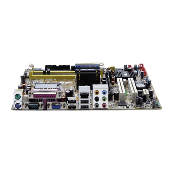
ASUS P5LD2-VM SE
Основные и самые важные характеристики модели собраны из надежных источников и по характеристикам можно найти похожие модели.
| Процессор | |
| Socket | LGA775 |
| Поддерживаемые процессоры | Intel Core 2 Extreme/Core 2 Duo/Pentium D/Pentium 4/Celeron D |
| Системная шина | 533 МГц — 1066 МГц |
| Поддержка Hyper-Threading | есть |
| Поддержка многоядерных процессоров | есть |
| Чипсет | |
| Чипсет | Intel 945G |
| BIOS | AMI |
| Поддержка SLI/CrossFire | нет |
| Память | |
| Память | DDR2 DIMM, 533 — 667 МГц |
| Количество слотов памяти | 2 |
| Поддержка двухканального режима | есть |
| Максимальный объем памяти | 2 Гб |
| Дисковые контроллеры | |
| IDE | количество слотов: 1, UltraDMA 100 |
| SATA | количество разъемов SATA 3Gb/s: 4 |
| Слоты расширения | |
| Слоты расширения | 1xPCI-E x16, 1xPCI-E x1, 2xPCI |
| Аудио/видео | |
| Звук | 7.1CH, HDA, на основе Realtek ALC 882 |
| Встроенный видеоадаптер | есть, на основе Intel GMA 950 |
| Сеть | |
| Ethernet | 1000 Мбит/с |
| Подключение | |
| Наличие интерфейсов | 8 USB, выход S/PDIF, 1xCOM, D-Sub, Ethernet, PS/2 (клавиатура), PS/2 (мышь), LPT |
| Разъемы на задней панели | 4 USB, 1xCOM, D-Sub, Ethernet, PS/2 (клавиатура), PS/2 (мышь), LPT |
| Основной разъем питания | 24-pin |
| Разъем питания процессора | 4-pin |
| Дополнительные параметры | |
| Форм-фактор | microATX |
Здесь представлен список самых частых и распространенных поломок и неисправностей у Материнских плат. Если у вас такая поломка то вам повезло, это типовая неисправность для ASUS P5LD2-VM SE и вы можете задать вопрос о том как ее устранить и вам быстро ответят или же прочитайте в вопросах и ответах ниже.
| Название поломки | Описание поломки | Действие |
|---|---|---|
| Разрыв Печатных Проводников | ||
| Обрыв Конденсаторов Или Резисторов | ||
| Короткое Замыкание В Электрических Цепях | ||
| Разрушение Разъемов И Слотов | ||
| Поломка Процессорного Разъема | ||
| Выгорание Портов | ||
| Микротрещины В Плате | ||
| Выход Из Строя Сетевого Адаптера | ||
| Перегрев Компонентов | ||
| Не Запускается При Включении | При Включении Не Загружается. В Биос Не Входит. Пост Код — А3 | |
| Какой Компонент | Подскажите Марку Траyзистора Q46? | |
| Не Работает Ps/2 | Сначала Отвалилась Клавиатура, А Через Некоторое Время 6 Коротких Гудков И Не Запускается | |
| Подключить Переднюю Панель | Не Могу Подключить Переднюю Панель | |
| Судя По Всему Отвал Биоса | Материнка Стартует Секунд На 5,Кулер Процессора Берет Обороты И Останавливается.и Так-Циклически,Без Остановок.запуск Невозможен.вечером Либо Завтра Буду Пытаться Его Восстановить,Потом Может Дополню | |
| Пропал Звук На Материнке | Пропал Звук На Материнке, Отображается Только Nvidia Hdmi. Переустановка Драйверов С Офсайта Не Помогла. | |
| Биос | При Старте Звук Через Промежетки Времени Примерно В 1-3 Мин Три Сигнала Потом Стартует Винда , Недавно Вообще Написал Cmos Setting Wrong И C7, Жму Del Меняется На B2 Чтоб Воити В Биос Три Сигнала По Одному Через Промеежутки Времени 1-3 Мин И Черный Экра | |
| Asus M2A-Vm Hdmi | Не Запускается Процессор Phenom Ii X4 945 Rev. C3, На Socket-Ам 3, Нет Даже Сигнала, Черный Экран | |
| Не Включается | После Замены Конденсаторов С34 И С35 Не Включается | |
| Черный Экран | Все Уже Перепробовал И Озу Менял И Переставлял И Ластиком Чистил, И Батарейку Вынимал И Измерял, И Видеокарту С Бп На Заведомо Годную Ставил Исход Один, Черный Экран И Speaker Издает 1 Длинный 2 Коротких, Если Я Не Путаю. | |
| Неправильно Отображается Память | При Установленной Памяти 4 Гигабайта В Биосе Отображается 8. Установил Одну Планку 2 Гига — Отображается 4 | |
В нашей базе сейчас зарегестрированно 18 353 сервиса в 513 города России, Беларусии, Казахстана и Украины.

КОМПРАЙЭКСПРЕСС — КОМПЬЮТЕРНЫЙ МАСТЕР-СЕРВИС
⭐
⭐
⭐
⭐
⭐
Адресс:
ул. Краснобогатырская, д. 13
Телефон:
79153203397
Сайт:
n/a
Время работы
Круглосуточно
АМПЕРВОЛЬТ
⭐
⭐
⭐
⭐
⭐
Адресс:
Сокольническая Слободка ул., д.10
Телефон:
74957965532
Сайт:
n/a
Время работы
Время работы не указано
СЕРВИС ЦЕНТР MUSIC-FIX MUSIC-FIX.RU
⭐
⭐
⭐
⭐
⭐
Адресс:
Южнопортовая 7
Телефон:
74993905854
Сайт:
n/a
Время работы
Будни: с 1000 до 2100
Суббота: с 1400 до 1900
Воскресенье: с 1400 до 1900
REMOBI
⭐
⭐
⭐
⭐
⭐
Адресс:
Каширское ш., 26
Телефон:
74993222524
Сайт:
n/a
Время работы
Ежедневно: с 1000 до 2100
СЕРВИС ЦЕНТР SEE-IT
⭐
⭐
⭐
⭐
⭐
Адресс:
Рязанский проспект д 77
Телефон:
74997542054
Сайт:
n/a
Время работы
Круглосуточно
Материнская плата Asus P5B-VM. Дохлая микросхема биос. Видео-отчет
5:47
Очень доволен
хочу
авпваы
Хочу купить
ирлдоьвап ькеьпрлджыкеь дзьакерджь щзрбкежбрь апкыезрбкыеджрбеджр щзапбкерл
Только приобрела,а инструкции нет
Только приобрела,а инструкции нет
Отвалился распрыскиватель
Проблема с изделием? Скачать инструкцию ASUS P5LD2-VM
инструкция по эксплуатации ASUS P5LD2-VM
Diplodocs поможет скачать инструкцию ASUS P5LD2-VM — QUICK START GUIDE .

Введите модель изделия ASUS.
Вы также можете скачать следующие инструкции, относящиеся к данному изделию:

Данное изделие, хотя и относится к торговой марке ASUS, могло быть произведено ASROCK после слияния, приобретения или смены названия.
Фрагмент инструкции: руководство пользователя ASUS P5LD2-VM — QUICK START GUIDE
Подробные указания по применению содержатся в руководстве пользователя.
Источник
Руководство по эксплуатации Asus P5LD2-VM
Руководство по эксплуатации для устройства Asus P5LD2-VM
Устройство: Asus P5LD2-VM
Размер: 4,04 MB
Добавлено: 2013-09-25 14:21:55
Количество страниц: 94
Печатать инструкцию
Как пользоваться?
Наша цель — обеспечить Вам самый быстрый доступ к руководству по эксплуатации устройства Asus P5LD2-VM . Пользуясь просмотром онлайн Вы можете быстро просмотреть содержание и перейти на страницу, на которой найдете решение своей проблемы с Asus P5LD2-VM .
Для Вашего удобства
Если просмотр руководства Asus P5LD2-VM непосредственно на этой странице для Вас неудобен, Вы можете воспользоваться двумя возможными решениями:
- Полноэкранный просмотр -, Чтобы удобно просматривать инструкцию (без скачивания на компьютер) Вы можете использовать режим полноэкранного просмотра. Чтобы запустить просмотр инструкции Asus P5LD2-VM на полном экране, используйте кнопку Полный экран .
- Скачивание на компьютер — Вы можете также скачать инструкцию Asus P5LD2-VM на свой компьютер и сохранить ее в своем архиве. Если ты все же не хотите занимать место на своем устройстве, Вы всегда можете скачать ее из ManualsBase.
Печатная версия
Многие предпочитают читать документы не на экране, а в печатной версии. Опция распечатки инструкции также предусмотрена и Вы можете воспользоваться ею нажав на ссылку, находящуюся выше — Печатать инструкцию . Вам не обязательно печатать всю инструкцию Asus P5LD2-VM а только некоторые страницы. Берегите бумагу.
Резюме
Ниже Вы найдете заявки которые находятся на очередных страницах инструкции для Asus P5LD2-VM . Если Вы хотите быстро просмотреть содержимое страниц, которые находятся на очередных страницах инструкции, Вы воспользоваться ими.
Краткое содержание страницы № 1
Краткое содержание страницы № 2
E1996 E1996 E1996 E1996 E1996 First Edition First Edition First Edition First Edition First Edition May 2005 May 2005 May 2005 May 2005 May 2005 Copyright © 2005 ASUSTeK COMPUTER INC. All Rights Reserved. No part of this manual, including the products and software described in it, may be reproduced, transmitted, transcribed, stored in a retrieval system, or translated into any language in any form or by any means, except documentation kept by the purchaser for backup purposes, without the expres
Краткое содержание страницы № 3
Contents Notices . vi Safety information . vii About this guide . viii Typography . ix P5LD2-VM specifications summary .
Краткое содержание страницы № 4
Contents 1.10 Connectors . 1-22 1.10.1 Rear panel connectors . 1-22 1.10.2 Internal connectors. 1-24 Chapter 2: BIOS setup Chapter 2: BIOS setup Chapter 2: BIOS setup Chapter 2: BIOS setup Chapter 2: BIOS setup 2.1 Managing and updating your BIOS . 2-2 2.1.1 Creating a bootable floppy disk.
Краткое содержание страницы № 5
Contents 2.5 Power menu. 2-29 2.5.1 Suspend Mode . 2-29 2.5.2 ACPI 2.0 Support . 2-29 2.5.3 ACPI APIC Support . 2-29 2.5.4 APM Configuration . 2-30 2.5.5 Hardware Monitor . 2-32 2.6 Boo
Краткое содержание страницы № 6
Notices Federal Communications Commission Statement Federal Communications Commission Statement Federal Communications Commission Statement Federal Communications Commission Statement Federal Communications Commission Statement This device complies with Part 15 of the FCC Rules. Operation is subject to the following two conditions: • This device may not cause harmful interference, and • This device must accept any interference received including interference that may cause undesired operation. T
Краткое содержание страницы № 7
Safety information Electrical safety Electrical safety Electrical safety Electrical safety Electrical safety • To prevent electrical shock hazard, disconnect the power cable from the electrical outlet before relocating the system. • When adding or removing devices to or from the system, ensure that the power cables for the devices are unplugged before the signal cables are connected. If possible, disconnect all power cables from the existing system before you add a device. • Before connecting or
Краткое содержание страницы № 8
About this guide This user guide contains the information you need when installing and configuring the motherboard. How this guide is organized How this guide is organized How this guide is organized How this guide is organized How this guide is organized This manual contains the following parts: • • • • • Chapter 1: Product introduction Chapter 1: Product introduction Chapter 1: Product introduction Chapter 1: Product introduction Chapter 1: Product introduction This chapter describes the featu
Краткое содержание страницы № 9
Conventions used in this guide Conventions used in this guide Conventions used in this guide Conventions used in this guide Conventions used in this guide To make sure that you perform certain tasks properly, take note of the following symbols used throughout this manual. DANGER/WARNING: DANGER/WARNING: DANGER/WARNING: DANGER/WARNING: DANGER/WARNING: Information to prevent injury to yourself when trying to complete a task. CAUTION: CAUTION: CAUTION: CAUTION: CAUTION: Information to prevent damag
Краткое содержание страницы № 10
P5LD2-VM specifications summary ® ® ® ® CPU CPU CPU CPU CPU LGA775 socket for Intel Pentium D/Intel Pentium 4 ® ® or Intel Celeron processors ® Compatible with Intel PCG 05B/05A and 04B/04A processors ® Supports Intel Enhanced Memory 64 Technology (EM64T) ® Supports Enhanced Intel SpeedStep Technology (EIST) ® Supports Intel Hyper-Threading Technology ® Chipset Chipset Chipset Chipset Chipset Northbridge: Intel 945G ® Southbridge: Intel ICH7 Front Side Bus Front Side Bus Front Side Bus Front Sid
Краткое содержание страницы № 11
P5LD2-VM specifications summary BIOS features BIOS features BIOS features BIOS features BIOS features 4 Mb Flash ROM, AMI BIOS, PnP, WfM2.0, DMI2.0, SM BIOS 2.3, ASUS EZ Flash, CrashFree BIOS2, C.P.R. (CPU Parameter Recall) Special features Special features Special features Special features Special features ASUS AI Overclocking ASUS EZ Flash ASUS CrashFree BIOS 2 ASUS MyLogo2™ ASUS CPR (CPU Parameter Recall) Industry standard Industry standard Industry standard Industry standard Industry standar
Краткое содержание страницы № 12
Краткое содержание страницы № 13
Краткое содержание страницы № 14
1.1 Welcome! ® ® ® ® ® Thank you for buying an ASUS Thank you for buying an ASUS Thank you for buying an ASUS P5LD2-VM motherboard! P5LD2-VM motherboard! P5LD2-VM motherboard! Thank you for buying an ASUS Thank you for buying an ASUS P5LD2-VM motherboard! P5LD2-VM motherboard! The motherboard delivers a host of new features and latest technologies, making it another standout in the long line of ASUS quality motherboards! Before you start installing the motherboard, and hardware devices on it, ch
Краткое содержание страницы № 15
® ® ® ® ® Intel Intel 945G chipset 945G chipset Intel Intel Intel 945G chipset 945G chipset 945G chipset ® The Intel 945G graphics memory controller hub (GMCH) and the ICH7 I/O controller hub provide the vital interfaces for the motherboard. The GMCH ® features the Intel Graphics Media Accelerator 900, an integrated graphics engine for enhanced 3D, 2D, and video capabilities. The GMCH provides the interface for a processor in the 775-land package with 533/800/1066 MHz front side bus (FSB), dual
Краткое содержание страницы № 16
8-channel high definition audio 8-channel high definition audio 8-channel high definition audio 8-channel high definition audio 8-channel high definition audio ® The onboard Realtek ALC882 8-channel high-definition audio CODEC provides 192 KHz/ 24-bit audio output, jack-sensing and restasking functions. With the 8-channel audio ports and S/PDIF interfaces, you can connect your computer to home theater decoders to produce crystal-clear digital audio. S/PDIF digital sound ready S/PDIF digita
Краткое содержание страницы № 17
1.4 Before you proceed Take note of the following precautions before you install motherboard components or change any motherboard settings. • Unplug the power cord from the wall socket before touching any component. • Use a grounded wrist strap or touch a safely grounded object or to a metal object, such as the power supply case, before handling components to avoid damaging them due to static electricity • Hold components by the edges to avoid touching the ICs on them. • Whenever you uninstall
Краткое содержание страницы № 18
1.5 Motherboard overview Before you install the motherboard, study the configuration of your chassis to ensure that the motherboard fits into it. Make sure to unplug the power cord before installing or removing the motherboard. Failure to do so can cause you physical injury and damage motherboard components. 1.5.1 1.5.1 Placement direction Placement direction 1.5.1 1.5.1 1.5.1 Placement direction Placement direction Placement direction When installing the motherboard, make sure that you place it
Краткое содержание страницы № 19
1.5.3 1.5.3 Motherboard layout Motherboard layout 1.5.3 1.5.3 1.5.3 Motherboard layout Motherboard layout Motherboard layout CPU_FAN PS/2KBMS T: Mouse B: Keyboard COM1 ATX12V LGA775 VGA1 F_USB12 LAN_USB34 ® Intel Top:Rear Speaker Out Center: GMCH Side Speaker Out Below: 945G Center/Subwoofer Top:Line In Center:Line Out CHA_FAN Below:Mic In PCIEX16 Intel PCI1 82573V Intel FWH ® SB_PWR 4Mb Intel ICH7 PCI2 SATA3 SATA4 CR2032 3V CD Lithium Cell SATA1 SATA2 PCIEX1_1 CMOS Power BUZZ CLRTC AAFP SPDIF_O
Краткое содержание страницы № 20
1.6 Central Processing Unit (CPU) The motherboard comes with a surface mount LGA775 socket designed for ® ® the Intel Pentium 4 processor in the 775-land package. ® ® • Your boxed Intel Pentium 4 LGA775 processor package should come with installation instructions for the CPU, fan and heatsink assembly. If the instructions in this section do not match the CPU documentation, follow the latter. • Upon purchase of the motherboard, make sure that the PnP cap is on the socket and the socket pins are n
Источник
Руководство по эксплуатации Asus Motherboard P5LD2-VM DH
Руководство по эксплуатации для устройства Asus Motherboard P5LD2-VM DH
Устройство: Asus Motherboard P5LD2-VM DH
Размер: 1,93 MB
Добавлено: 2013-05-14 14:33:51
Количество страниц: 98
Печатать инструкцию
Как пользоваться?
Наша цель — обеспечить Вам самый быстрый доступ к руководству по эксплуатации устройства Asus Motherboard P5LD2-VM DH . Пользуясь просмотром онлайн Вы можете быстро просмотреть содержание и перейти на страницу, на которой найдете решение своей проблемы с Asus Motherboard P5LD2-VM DH .
Для Вашего удобства
Если просмотр руководства Asus Motherboard P5LD2-VM DH непосредственно на этой странице для Вас неудобен, Вы можете воспользоваться двумя возможными решениями:
- Полноэкранный просмотр -, Чтобы удобно просматривать инструкцию (без скачивания на компьютер) Вы можете использовать режим полноэкранного просмотра. Чтобы запустить просмотр инструкции Asus Motherboard P5LD2-VM DH на полном экране, используйте кнопку Полный экран .
- Скачивание на компьютер — Вы можете также скачать инструкцию Asus Motherboard P5LD2-VM DH на свой компьютер и сохранить ее в своем архиве. Если ты все же не хотите занимать место на своем устройстве, Вы всегда можете скачать ее из ManualsBase.
Печатная версия
Многие предпочитают читать документы не на экране, а в печатной версии. Опция распечатки инструкции также предусмотрена и Вы можете воспользоваться ею нажав на ссылку, находящуюся выше — Печатать инструкцию . Вам не обязательно печатать всю инструкцию Asus Motherboard P5LD2-VM DH а только некоторые страницы. Берегите бумагу.
Резюме
Ниже Вы найдете заявки которые находятся на очередных страницах инструкции для Asus Motherboard P5LD2-VM DH . Если Вы хотите быстро просмотреть содержимое страниц, которые находятся на очередных страницах инструкции, Вы воспользоваться ими.
Краткое содержание страницы № 1
Краткое содержание страницы № 2
E2464 E2464 E2464 E2464 E2464 First Edition V1 First Edition V1 First Edition V1 First Edition V1 First Edition V1 March 2006 March 2006 March 2006 March 2006 March 2006 Copyright © 2006 ASUSTeK COMPUTER INC. All Rights Reserved. No part of this manual, including the products and software described in it, may be reproduced, transmitted, transcribed, stored in a retrieval system, or translated into any language in any form or by any means, except documentation kept by the purchaser for backup pur
Краткое содержание страницы № 3
Contents Notices . vi Safety information . vii About this guide . viii Typography . ix P5LD2-VM specifications summary .
Краткое содержание страницы № 4
Contents 1.10 Connectors . 1-24 1.10.1 Rear panel connectors . 1-24 1.10.2 Internal connectors. 1-26 Chapter 2: BIOS setup Chapter 2: BIOS setup Chapter 2: BIOS setup Chapter 2: BIOS setup Chapter 2: BIOS setup 2.1 Managing and updating your BIOS . 2-2 2.1.1 Creating a bootable floppy disk.
Краткое содержание страницы № 5
Contents 2.5 Power menu. 2-29 2.5.1 Suspend Mode . 2-29 2.5.2 Repost Video on S3 Resume . 2-29 2.5.3 ACPI 2.0 Support . 2-29 2.5.4 ACPI APIC Support . 2-29 2.5.5 APM Configuration . 2-30 2.5.6 Hardware
Краткое содержание страницы № 6
Notices Federal Communications Commission Statement Federal Communications Commission Statement Federal Communications Commission Statement Federal Communications Commission Statement Federal Communications Commission Statement This device complies with Part 15 of the FCC Rules. Operation is subject to the following two conditions: • This device may not cause harmful interference, and • This device must accept any interference received including interference that may cause undesired operation. T
Краткое содержание страницы № 7
Safety information Electrical safety Electrical safety Electrical safety Electrical safety Electrical safety • To prevent electrical shock hazard, disconnect the power cable from the electrical outlet before relocating the system. • When adding or removing devices to or from the system, ensure that the power cables for the devices are unplugged before the signal cables are connected. If possible, disconnect all power cables from the existing system before you add a device. • Before connecting or
Краткое содержание страницы № 8
About this guide This user guide contains the information you need when installing and configuring the motherboard. How this guide is organized How this guide is organized How this guide is organized How this guide is organized How this guide is organized This manual contains the following parts: • • • • • Chapter 1: Product introduction Chapter 1: Product introduction Chapter 1: Product introduction Chapter 1: Product introduction Chapter 1: Product introduction This chapter describes the featu
Краткое содержание страницы № 9
Conventions used in this guide Conventions used in this guide Conventions used in this guide Conventions used in this guide Conventions used in this guide To make sure that you perform certain tasks properly, take note of the following symbols used throughout this manual. DANGER/WARNING: DANGER/WARNING: DANGER/WARNING: DANGER/WARNING: DANGER/WARNING: Information to prevent injury to yourself when trying to complete a task. CAUTION: CAUTION: CAUTION: CAUTION: CAUTION: Information to prevent damag
Краткое содержание страницы № 10
P5LD2-VM DH specifications summary ® ® ® ® CPU CPU CPU CPU CPU LGA775 socket for Intel Pentium D/Intel Pentium 4 ® ® or Intel Celeron processors ® Compatible with Intel PCG 05B/05A and 04B/04A processors ® Supports Intel Enhanced Memory 64 Technology (EM64T) ® Supports Enhanced Intel SpeedStep Technology (EIST) ® Supports Intel Hyper-Threading Technology ® Chipset Chipset Chipset Chipset Chipset Northbridge: Intel 945G ® Southbridge: Intel ICH7 DH Supports Intel Viiv™ Technology Front Side Bus F
Краткое содержание страницы № 11
P5LD2-VM DH specifications summary BIOS features BIOS features BIOS features BIOS features BIOS features 8 Mb Flash ROM, AMI BIOS, PnP, WfM2.0, DMI2.0, SM BIOS 2.3, ASUS EZ Flash, CrashFree BIOS2, Intel Quick Resume Special features Special features Special features Special features Special features ASUS EZ Flash ASUS CrashFree BIOS 2 ASUS MyLogo™ ASUS CPR (CPU Parameter Recall) Industry standard Industry standard Industry standard Industry standard Industry standard PCI 2.2, USB 2.0 Manageabili
Краткое содержание страницы № 12
Краткое содержание страницы № 13
Краткое содержание страницы № 14
1.1 Welcome! ® ® ® ® ® Thank you for buying an ASUS Thank you for buying an ASUS Thank you for buying an ASUS Thank you for buying an ASUS Thank you for buying an ASUS P5LD2-VM DH motherboard! P5LD2-VM DH motherboard! P5LD2-VM DH motherboard! P5LD2-VM DH motherboard! P5LD2-VM DH motherboard! The motherboard delivers a host of new features and latest technologies, making it another standout in the long line of ASUS quality motherboards! Before you start installing the motherboard, and hardware de
Краткое содержание страницы № 15
Dual-core processors contain two physical CPU cores with dedicated L2 caches to meet demands for more powerful processing. Intel(R)’s 65nm process is the most advanced chip manufacturing technology, delivering breakthrough performance, enhanced media experience, and low power consumption. Intel(R) 65nm dual-core processors utilize the latest package technologies for a thinner, lighter design without compromising performance. ® ® ® ® ® Intel Intel 945G chipset 945G chipset Intel Intel Intel 945G
Краткое содержание страницы № 16
. PCI Express™ interface PCI Express™ interface PCI Express™ interface PCI Express™ interface PCI Express™ interface The motherboard fully supports PCI Express, the latest I/O interconnect technology that speeds up the PCI bus. PCI Express features point-to-point serial interconnections between devices and allows higher clockspeeds by carrying data in packets. This high speed interface is software compatible with existing PCI specifications. See page 1-22 for details. 64-bit CPU support 6
Краткое содержание страницы № 17
1.3.2 1.3.2 1.3.2 1.3.2 1.3.2 Innovative ASUS features Innovative ASUS features Innovative ASUS features Innovative ASUS features Innovative ASUS features CrashFree BIOS 2 CrashFree BIOS 2 CrashFree BIOS 2 CrashFree BIOS 2 CrashFree BIOS 2 This feature allows you to restore the original BIOS data from the support CD in case when the BIOS codes and data are corrupted. This protection eliminates the need to buy a replacement ROM chip. See details on page 2-6. ASUS MyLogo™ ASUS MyLogo™ ASUS MyLogo™
Краткое содержание страницы № 18
1.4 Before you proceed Take note of the following precautions before you install motherboard components or change any motherboard settings. • Unplug the power cord from the wall socket before touching any component. • Use a grounded wrist strap or touch a safely grounded object or a metal object, such as the power supply case, before handling components to avoid damaging them due to static electricity • Hold components by the edges to avoid touching the ICs on them. • Whenever you uninstall any
Краткое содержание страницы № 19
1.5 Motherboard overview Before you install the motherboard, study the configuration of your chassis to ensure that the motherboard fits into it. Make sure to unplug the power cord before installing or removing the motherboard. Failure to do so can cause you physical injury and damage motherboard components. 1.5.1 1.5.1 1.5.1 1.5.1 1.5.1 Placement direction Placement direction Placement direction Placement direction Placement direction When installing the motherboard, make sure that you place it
Краткое содержание страницы № 20
1.5.3 1.5.3 Motherboard layout Motherboard layout 1.5.3 1.5.3 1.5.3 Motherboard layout Motherboard layout Motherboard layout CPU_FAN PS/2KBMS T: Mouse B: Keyboard COM1 ATX12V LGA775 VGA1 F_USB12 LAN_USB34 ® Intel Top:Rear Speaker Out Center: GMCH Side Speaker Out Below: 945G Center/Subwoofer Top:Line In Center:Line Out CHA_FAN Below:Mic In PCIEX16 Intel PCI1 82573V Intel FWH ® SB_PWR 4Mb Intel ICH7 DH PCI2 SATA3 SATA4 CR2032 3V CD Lithium Cell SATA1 SATA2 PCIEX1_1 CMOS Power BUZZ CLRTC AAFP SPDI
Источник
Asus P5E64 WS Professional Motherboard Guida d’installazione
Бренд:
Asus
Категория:
Mixer/food processor accessories
Размер:
43 MB
Страниц:
721
Язык(и):
Болгарский, Чешский, Английский, Испанский, Хорватский, Венгерский, Индонезийский, Итальянский, Корейский, Польский, Португальский, Румынский, Русский, Турецкий, Вьетнамский
Открыть в новой вкладке
- Инструкции и руководства
- Бренды
- ASUS
- P5LD2-VM SE
- Справочник Пользователя
![]()