Посмотреть инструкция для Asus P8Z77-V LE PLUS бесплатно. Руководство относится к категории материнские платы, 1 человек(а) дали ему среднюю оценку 7.5. Руководство доступно на следующих языках: английский. У вас есть вопрос о Asus P8Z77-V LE PLUS или вам нужна помощь? Задайте свой вопрос здесь
Не можете найти ответ на свой вопрос в руководстве? Вы можете найти ответ на свой вопрос ниже, в разделе часто задаваемых вопросов о Asus P8Z77-V LE PLUS.
Какая ширина Asus P8Z77-V LE PLUS?
Какая толщина Asus P8Z77-V LE PLUS?
Инструкция Asus P8Z77-V LE PLUS доступно в русский?
Не нашли свой вопрос? Задайте свой вопрос здесь
-
Contents
-
Table of Contents
-
Bookmarks
Quick Links
Related Manuals for Asus P8Z77-V LE PLUS
Summary of Contents for Asus P8Z77-V LE PLUS
-
Page 1
P8Z77-V LE PLUS… -
Page 2
Product warranty or service will not be extended if: (1) the product is repaired, modified or altered, unless such repair, modification of alteration is authorized in writing by ASUS; or (2) the serial number of the product is defaced or missing. -
Page 3: Table Of Contents
Contents Safety information … vi About this guide … vii P8Z77-V LE PLUS specifications summary … ix Chapter 1: Product introduction Welcome! … 1-1 Package contents … 1-1 Special features … 1-2 1.3.1 Product highlights … 1-2 1.3.2 Dual Intelligent Processors 3 with Smart DIGI+ … 1-4 1.3.3…
-
Page 4
Network Stack … 3-26 Monitor menu … 3-27 Boot menu … 3-30 Tools menu … 3-32 3.8.1 ASUS EZ Flash 2 Utility … 3-32 3.8.2 ASUS O.C. Profile … 3-32 3.8.3 ASUS SPD Information … 3-33 Exit menu … 3-34 3.10… -
Page 5
Contents 4.3.8 Ai Charger+ … 4-16 4.3.9 USB Charger+ … 4-17 4.3.10 USB 3.0 Boost … 4-19 4.3.11 Network iControl … 4-20 4.3.12 USB BIOS Flashback Wizard … 4-24 4.3.13 MyLogo2 … 4-26 4.3.14 Audio configurations … 4-28 Introduction to Intel 4.4.1 System Requirements for Intel technologies … -
Page 6: Safety Information
Safety information Electrical safety • To prevent electrical shock hazard, disconnect the power cable from the electrical outlet before relocating the system. • When adding or removing devices to or from the system, ensure that the power cables for the devices are unplugged before the signal cables are connected. If possible, disconnect all power cables from the existing system before you add a device.
-
Page 7: About This Guide
Where to find more information Refer to the following sources for additional information and for product and software updates. ASUS websites The ASUS website provides updated information on ASUS hardware and software products. Refer to the ASUS contact information. Optional documentation Your product package may include optional documentation, such as warranty flyers, that may have been added by your dealer.
-
Page 8: Conventions Used In This Guide
Conventions used in this guide To ensure that you perform certain tasks properly, take note of the following symbols used throughout this manual. DANGER/WARNING: Information to prevent injury to yourself when trying to complete a task. CAUTION: Information to prevent damage to the components when trying to complete a task.
-
Page 9: P8Z77-V Le Plus Specifications Summary
P8Z77-V LE PLUS specifications summary LGA1155 socket for Intel Core™ i3 / Pentium Supports 22nm / 32nm CPU Supports Intel * The Intel types. ** Refer to www.asus.com for Intel Chipset Intel Z77 Express Chipset ® Memory 4 x DIMMs, max. 32GB, DDR3 2400(O.C.) / 2200(O.C.) / 2133(O.C.) / 1866 (O.C.) / 1600 / 1333 / 1066 MHz, non-ECC, un-buffered memory…
-
Page 10
Intel ® — 10 x USB 2.0 ports (8 ports at mid-board, 2 ports at back panel) ASMedia USB 3.0 controllers — supports ASUS USB 3.0 Boost UASP Mode — 2 x USB 3.0 ports at the back panel (blue) * The USB 3.0 ports only support Windows… -
Page 11
— Auto Tuning, TurboV, GPU Boost, TPU switch ASUS Exclusive Features — ASUS USB 3.0 Boost featuring the latest USB 3.0 UASP standard — ASUS Network iControl featuring instant network bandwidth domination for top network program in use — ASUS USB Charger+ featuring quick-charging function for all smart… -
Page 12
ATX Form Factor, 12”x 9.6” (30.5cm x 24.4cm) * Specifications are subject to change without notice. ACPI 2.0a, Multi-language BIOS, ASUS EZ Flash 2, ASUS CrashFree BIOS 3, F12 PrintScreen Function, F3 Shortcut Function and ASUS DRAM SPD (Serial Presence Detect) Memory information… -
Page 13: Chapter 1: Product Introduction
Thank you for buying an ASUS The motherboard delivers a host of new features and latest technologies, making it another standout in the long line of ASUS quality motherboards! Before you start installing the motherboard, and hardware devices on it, check the items in your package with the list below.
-
Page 14: Special Features
Complete USB 3.0 Integration ASUS facilitates strategic USB 3.0 accessibility for both the front and rear panel — 6 USB 3.0 ports in total. Experience the latest plug & play connectivity at speeds up to 10 times faster than USB 2.0. The P8Z77-V LE PLUS affords greater convenience to high speed connectivity.
-
Page 15: Intel Smart Response Technology
Z77 Express chipset natively supports the next-generation Serial ATA (SATA) ® interface, delivering up to 6.0 Gb/s data transfer. ASUS provides extra SATA 6.0 Gb/s ports with enhanced scalability, faster data retrieval, and double the bandwidth of current bus systems.
-
Page 16: Dual Intelligent Processors 3 With Smart Digi
12.5 power design, ASUS once again leaps to the future of innovation. The Ultimate Turbo Processor Unleash your performance with ASUS’ simple onboard switch or AI Suite II utility. The TPU chip offers precise voltage control and advanced monitoring through Auto Tuning and TurboV functions.
-
Page 17: Asus Exclusive Features
ASUS TurboV Easy, Real-Time O.C. Tunings Feel the adrenaline rush of real-time OC-now a reality with the ASUS TurboV. This easy OC tool allows you to overclock without exiting or rebooting the OS; and its user-friendly interface makes overclock with just a few clicks away. Moreover, the ASUS OC profiles in TurboV provides the best O.C.
-
Page 18: Usb Charger
AI Suite II One-stop Access to Innovative ASUS Features With its user-friendly interface, ASUS AI Suite II consolidates all the exclusive ASUS features into one simple to use software package. It allows you to supervise overclocking, energy management, fan speed control, voltage and sensor readings. This all-in-one software offers diverse and ease to use functions, with no need to switch back and forth between different utilities.
-
Page 19: Asus Quiet Thermal Solutions
ASUS DRAM SPD (Serial Presence Detect) information detecting faulty DIMMs, and helping with difficult POST situations. ASUS EZ-Flash 2 ASUS EZ Flash 2 is a user-friendly utility that allows you to update the BIOS without using a bootable floppy disk or an OS-based utility. ASUS Q-Slot ASUS Q-Slot is designed to speed up and simplify the DIY process to enhance your DIY experience.
-
Page 20: Other Special Features
The motherboard is European Union´s Energy-related Products (ErP) ready, and ErP requires products to meet certain energy efficiency requirements in regards to energy consumptions. This is in line with ASUS vision of creating environment-friendly and energy- efficient products through product design and innovation to reduce carbon footprint of the product and thus mitigate environmental impacts.
-
Page 21: Chapter 2: Hardware Information
• • • • ASUS P8Z77-V LE PLUS Chapter 2 Unplug the power cord from the wall socket before touching any component. Before handling components, use a grounded wrist strap or touch a safely grounded object or a metal object, such as the power supply case, to avoid damaging them due to static electricity.
-
Page 22: Motherboard Overview
SPDIF_OUT AAFP Refer to 2.2.8 Connectors and 2.3.10 Rear panel connection for more information about rear panel connectors and internal connectors. 24.4cm(9.6in) CPU_FAN CHA_FAN2 EPU_LED TPU_LED DIGI+ Lithium Cell P8Z77-V LE PLUS PCIEX16_1 PCI1 PCIEX16_2 PCI2 64Mb 1083 BIOS PCIEX16_3…
-
Page 23: Layout Contents
System panel connector (20-8 pin PANEL) BIOS Flashback button (BIOS_FLBK) USB 2.0 connectors (10-1 pin USB3~10) Serial port connectors (10-1 pin COM1) Front panel audio connector (10-1 pin AAFP) Digital audio connector (4-1 pin SPDIF_OUT) ASUS P8Z77-V LE PLUS Page 2-25 2-27 2-21 2-18…
-
Page 24: Central Processing Unit (Cpu)
Contact your retailer immediately if the PnP cap is missing, or if you see any damage to the PnP cap/socket contacts/motherboard components. ASUS will shoulder the cost of repair only if the damage is shipment/ transit-related.
-
Page 25: System Memory
A DDR3 module is notched differently from a DDR or DDR2 module. DO NOT install a DDR or DDR2 memory module to the DDR3 slot. P8Z77-V LE PLUS P8Z77-V LE PLUS 240-pin DDR3 DIMM sockets Recommended memory configurations We recommend that you install the memory modules from the blue slots for better overclocking capability.
-
Page 26: Memory Configurations
For system stability, use a more efficient memory cooling system to support a full memory load (4 DIMMs) or overclocking condition. Visit the ASUS website for the latest QVL. P8Z77-V LE PLUS Motherboard Qualified Vendors Lists (QVL) DDR3 2400MHz capability Vendors Part No.
-
Page 27
P8Z77-V LE PLUS Motherboard Qualified Vendors Lists (QVL) DDR3 2250MHz capability Vendors Part No. Size Kingston KHX2250C9D3T1K2/4GX(XMP) 4GB(2x 2GB) * The memory modules in 2250MHz and above are supported on Intel by this motherboard; however, the actual frequency support varies depending on the O.C. margin of the installed CPU. -
Page 28
P8Z77-V LE PLUS Motherboard Qualified Vendors Lists (QVL) DDR31866MHz capability Vendors Part No. Size CORSAIR CMT4GX3M2A1866C9(XMP) 4GB(2 x 2GB) DS CORSAIR CMT6GX3MA1866C9(XMP) 6GB(3 x 2GB) DS CORSAIR CMZ8GX3M2A1866C9(XMP) 8GB(2 x 4GB) DS G.SKILL F3-14900CL9D- 8GB(2 x 4GB) DS 8GBXL(XMP) G.SKILL… -
Page 29
P8Z77-V LE PLUS Motherboard Qualified Vendors Lists (QVL) DDR3 1600MHz capability Vendors Paart No. KINGSTON KHX1600C9D3T1BK3/ 12GX(XMP) KINGSTON KHX1600C9AD3/2G KINGSTON KVR1600D3N11/2G-ES KINGSTON KHX1600C7D3K2/4GX(XMP) KINGSTON KHX1600C8D3K2/4GX(XMP) KINGSTON KHX1600C8D3T1K2/4GX(XMP) 4GB(2 x 2GB) DS — KINGSTON KHX1600C9D3K2/4GX(XMP) KINGSTON KHX1600C9D3LK2/4GX(XMP) KINGSTON KHX1600C9D3X2K2/4GX(XMP) 4GB(2 x 2GB) DS -… -
Page 30
P8Z77-V LE PLUS Motherboard Qualified Vendors Lists (QVL) DDR3 1333MHz capability Vendors Part No. Size Crucial CT12864BA1339.8FF Crucial CT25664BA1339.16FF Crucial BL25664BN13 37.16FF (XMP) (3 x 2GB) ELPIDA EBJ10UE8EDF0-DJ-F ELPIDA EBJ21UE8EDF0-DJ-F G.SKILL F3-10600CL8 D-2GBHK(XMP) G.SKILL F3-10600CL 9D-2GBNQ (2 x 1GB) G.SKILL… -
Page 31
P8Z77-V LE PLUS Motherboard Qualified Vendors Lists (QVL) DDR3 1333MHz capability Vendors Part No. Size Micron MT8JTF25664AZ- 1G4D1 Micron MT8JTF25664AZ- 1G4M1 Micron MT16JTF25664AZ- 1G4F1 Micron MT16JTF51264AZ- 1G4D1 NANYA NT4GC64B8HG0NF- AL7F8G73F-DJ2 AL8F8G73F-DJ2 SAMSUNG M378B2873FHS-CH9 SAMSUNG M378B5773DH0-CH9 SAMSUNG M378B5673FH0-CH9 SAMSUNG M378B5273CH0-CH9 SAMSUNG… -
Page 32
P8Z77-V LE PLUS Motherboard Qualified Vendors Lists (QVL) DDR3 1066MHz capability Vendors Part No. Size SS/ Crucial CT12864BA1067.8FF 1GB SS Crucial CT25664BA1067.16FF 2GB DS ELPIDA EBJ10UE8EDF0-AE-F 1GB SS ELPIDA EBJ21UE8EDF0-AE-F 2GB DS KINGSTON KVR1066D3N7/1G 1GB SS (low profile) KINGSTON KVR1066D3N7/2G… -
Page 33: Expansion Slots
PCIe 2.0 x16_3 slot [black] (at x4 mode, compatible with PCIe x1 and x4 devices) PCI Express operating mode VGA configuration PCIe 3.0/2.0 x16_1 Single VGA/PCIe card (Recommend for single VGA) Dual VGA/PCIe card ASUS P8Z77-V LE PLUS P8Z77-V LE PLUS PCIe 3.0/2.0 x16_2 2-13…
-
Page 34: Irq Assignments For This Motherboard
• In single VGA card mode, use the PCIe 3.0/2.0 x16_1 slot (navy blue) for a PCI Express x16 graphics card to get better performance. • In CrossFireX™ or SLI™ mode, use the PCIe 3.0/2.0 x16_1 and PCIe 3.0/2.0 x16_2 slots for PCI Express x16 graphics cards to get better performance.
-
Page 35: Clear Rtc Ram
P8Z77-V LE PLUS (Default) P8Z77-V LE PLUS Clear RTC RAM To erase the RTC RAM Turn OFF the computer and unplug the power cord. Move the jumper cap from pins 1-2 (default) to pins 2-3. Keep the cap on pins 2-3 for about 5–10 seconds, then move the cap back to pins 1-2.
-
Page 36: Onboard Switches
BIOS default settings. A message will appear during POST reminding you that the BIOS has been restored to its default settings. • We recommend that you download and update to the latest BIOS version from the ASUS website at www.asus.com after using the MemOK! function. 2-16 OS environment. ®…
-
Page 37
Turning this switch to Enable will automatically optimize the system for fast, yet stable clock speeds. P8Z77-V LE PLUS P8Z77-V LE PLUS TPU Boost switch • To ensure system performance, turn the switch setting to Enable when the system is powered off. -
Page 38
EPU switch This switch allows you to enable or disable the EPU function. P8Z77-V LE PLUS P8Z77-V LE PLUS EPU Boost switch To ensure system performance, turn the switch setting to Enable when the system is powered off. • The EPU LED near the TPU switch lights when the switch setting is turned to Enable. -
Page 39
P8Z77-V LE PLUS P8Z77-V LE PLUS BIOS Flashback switch Download the USB BIOS Flashback wizard from the ASUS service website (www.asus. com). Save it to a USB portable disk, and place it in the root directory. Plug the USB flash drive into the bottom port of ESATA6G_USB3_12 connector in back I/O. -
Page 40: Onboard Leds
The illustration below shows the location of the onboard LED. P8Z77-V LE PLUS P8Z77-V LE PLUS Onboard LED DRAM LED DRAM LED checks the DRAM in sequence during motherboard booting process. If an error is found, the LED next to the error device will continue lighting until the problem is solved.
-
Page 41
BIOS_FLBK LED The BIOS_FLBK LED lights when the BIOS-FLBK function is enabled. P8Z77-V LE PLUS P8Z77-V LE PLUS BIOS Flashback LED EPU LED The EPU LED lights when the EPU switch is turned to Enable. P8Z77-V LE PLUS P8Z77-V LE PLUS EPU Boost LED TPU LED The TPU LED lights when the TPU switch is turned to Enable. -
Page 42: Internal Connectors
Intel chipset. P8Z77-V LE PLUS P8Z77-V LE PLUS Intel SATA 6.0Gb/s connectors • These connectors are set to [AHCI] by default. If you intend to create a Serial ATA RAID set using these connectors, set the SATA Mode Selection item in the BIOS to [RAID].
-
Page 43
Intel chipset. P8Z77-V LE PLUS P8Z77-V LE PLUS Intel SATA 3.0Gb/s connectors • These connectors are set to [AHCI] by default. If you intend to create a Serial ATA RAID set using these connectors, set the SATA Mode Selection item in the BIOS to [RAID]. -
Page 44: Front Panel Audio Connector
HD Audio or legacy AC`97 audio standard. Connect one end of the front panel audio I/O module cable to this connector. P8Z77-V LE PLUS P8Z77-V LE PLUS Front panel audio connector • We recommend that you connect a high-definition front panel audio module to this connector to avail of the motherboard’s high-definition audio capability.
-
Page 45
S/PDIF Out module cable to this connector, then install the module to a slot opening at the back of the system chassis. P8Z77-V LE PLUS P8Z77-V LE PLUS Digital audio connector The S/PDIF module is purchased separately. CPU and chassis fan connectors (4-pin CPU_FAN, 4-pin CHA_FAN1/2/3) Connect the fan cables to the fan connectors on the motherboard, ensuring that the black wire of each cable matches the ground pin of the connector. -
Page 46
USB 3.0 solution. P8Z77-V LE PLUS P8Z77-V LE PLUS USB3.0 front panel connector • You can connect the ASUS front panel USB 3.0 bracket to this connector to obtain the front panel USB 3.0 solution. • Due to Intel operating system. -
Page 47
The system may become unstable or may not boot up if the power is inadequate. • If you are uncertain about the minimum power supply requirement for your system, refer to the Recommended Power Supply Wattage Calculator at http://support.asus. com/PowerSupplyCalculator/PSCalculator.aspx?SLanguage=en-us for details. ASUS P8Z77-V LE PLUS SATA6G_E1 SATA 6.0 Gb/s connector… -
Page 48: System Panel Connector
System panel connector (20-8 pin PANEL) This connector supports several chassis-mounted functions. P8Z77-V LE PLUS P8Z77-V LE PLUS System panel connector • System power LED (2-pin PLED) This 2-pin connector is for the system power LED. Connect the chassis power LED cable to this connector.
-
Page 49: Building Your Computer System
Intel LGA 1155 CPU DIMM SATA optical disc drive (optional) The tools and components in the table above are not included in the motherboard package. ASUS P8Z77-V LE PLUS Philips (cross) screwdriver Power supply unit Intel LGA1155 compatible CPU Fan…
-
Page 50: Cpu Installation
2.3.2 CPU installation The LGA1156 CPU is incompatible with the LGA1155 socket. DO NOT install a LGA1156 CPU on the LGA1155 socket. 2-30 Chapter 2: Hardware information…
-
Page 51
ASUS P8Z77-V LE PLUS 2-31… -
Page 52: Cpu Heatsink And Fan Assembly Installation
2.3.3 CPU heatsink and fan assembly installation To install the CPU heatsink and fan assembly 2-32 Apply the Thermal Interface Material to the CPU heatsink and CPU before you install the heatsink and fan if necessary. Chapter 2: Hardware information…
-
Page 53
To uninstall the CPU heatsink and fan assembly ASUS P8Z77-V LE PLUS 2-33… -
Page 54: Dimm Installation
2.3.4 DIMM installation To remove a DIMM 2-34 Chapter 2: Hardware information…
-
Page 55: Motherboard Installation
2.3.5 Motherboard installation The diagrams in this section are for reference only. The motherboard layout may vary with models, but the installation steps remain the same. ASUS P8Z77-V LE PLUS 2-35…
-
Page 56
P8Z77-V LE PLUS DO NOT overtighten the screws! Doing so can damage the motherboard. 2-36 Chapter 2: Hardware information… -
Page 57: Atx Power Connection
2.3.6 ATX Power connection ASUS P8Z77-V LE PLUS 2-37…
-
Page 58: Sata Device Connection
2.3.7 SATA device connection 2-38 Chapter 2: Hardware information…
-
Page 59: Front I/O Connector
2.3.8 Front I/O Connector To install the system panel connector To install USB 2.0 Connector To install front panel audio connector AAFP USB 2.0 To install USB 3.0 Connector USB 3.0 ASUS P8Z77-V LE PLUS 2-39…
-
Page 60: Expansion Card Installation
2.3.9 Expansion Card installation To install PCIe x16 cards To install PCIe x1 cards To install PCI cards 2-40 Chapter 2: Hardware information…
-
Page 61: Rear Panel Connection
ASUS P8Z77-V LE PLUS ASMedia USB 3.0 ports 1 and 2, support ASUS USB 3.0 Boost UASP Mode Intel USB 3.0 ports 1 and 2, support ASUS USB 3.0 Boost UASP Mode. Bottom port supports USB BIOS Flashback and USB Charger+…
-
Page 62: Lan Port Led Indications
• This motherboard comes with multiple VGA output that features desktop extension on two monitors. You can connect two monitors to any two of the onboard VGA, DVI-D, HDMI, and DisplayPort ports. • DVI-D cannot be converted to output RGB signal to CRT and is not compatible with DVI-I.
-
Page 63: Audio I/O Connections
2.3.11 Audio I/O connections Audio I/O ports Connect to Headphone and Mic Connect to Stereo Speakers Connect to 2.1 channel Speakers ASUS P8Z77-V LE PLUS 2-43…
-
Page 64
Connect to 4.1 channel Speakers Connect to 5.1 channel Speakers Connect to 7.1 channel Speakers 2-44 Chapter 2: Hardware information… -
Page 65: Starting Up For The First Time
BIOS setting. Pressing the power switch for more than four seconds lets the system enter the soft-off mode regardless of the BIOS setting. ASUS P8Z77-V LE PLUS Description VGA detected Quick boot set to disabled…
-
Page 66
2-46 Chapter 2: Hardware information… -
Page 67: Chapter 3: Bios Setup
Chapter 3: Knowing BIOS The ASUS UEFI BIOS offers a user-friendly interface that goes beyond traditional keyboard-only BIOS controls to enable more flexible and convenient mouse input. Users can easily navigate the UEFI BIOS with the same smoothness as their operating system.
-
Page 68: Ez Mode
Displays the CPU/motherboard temperature, CPU/5V/3.3V/12V voltage output, CPU/chassis/power fan speed UEFI BIOS Utility — EZ Mode P8Z77-V LE PLUS BIOS Version : 0306 CPU Type : Genuine Intel(R) CPU @ 2.90GHz Monday [9/13/2010] Total Memory : 1024 MB (DDR3 1033MHz)
-
Page 69: Advanced Mode
Boot For changing the system boot configuration Tool For configuring options for special functions Exit For selecting the exit options and loading default settings ASUS P8Z77-V LE PLUS Configuration fields Advanced Monitor Boot Enabled/Disabled the Marvell Storage Enabled Controller.
-
Page 70: Menu Items
Menu items The highlighted item on the menu bar displays the specific items for that menu. For example, selecting Main shows the Main menu items. The other items (Ai Tweaker, Advanced, Monitor, Boot, Tool, and Exit) on the menu bar have their respective menu items.
-
Page 71: Main Menu
RTC RAM. The Administrator or User Password items on top of the screen show the default • Not Installed. After you set a password, these items show Installed. ASUS P8Z77-V LE PLUS Advanced Monitor Boot Choose the system default language…
-
Page 72: Administrator Password
Administrator Password If you have set an administrator password, we recommend that you enter the administrator password for accessing the system. Otherwise, you might be able to see or change only selected fields in the BIOS setup program. To set an administrator password: Select the Administrator Password item and press <Enter>.
-
Page 73: Ai Tweaker Menu
Be cautious when changing the settings of the Ai Tweaker menu items. Incorrect field values can cause the system to malfunction. The configuration options for this section vary depending on the CPU and DIMM model you installed on the motherboard. Scroll down to display the following items: ASUS P8Z77-V LE PLUS…
-
Page 74
This item appears only when you set the Ai Overclocking Tuner item to [X.M.P.] and allows you to select the X.M.P. mode supported by your memory module. Configuration options: [Profile #1] [ Profile #2] ASUS MultiCore Enhancement [Enabled] [Enabled] Select this option for maximum performance under XMP/Manual/User define memory frequency mode. -
Page 75
Saving Mode] [Medium Power Saving Mode] [Max Power Saving Mode] OC Tuner OC Tuner automatically overclocks the frequency and voltage of CPU and DRAM for enhancing the system performance. Configuration options: [OK] [Cancel] ASUS P8Z77-V LE PLUS Configuration options: [Auto] [DDR3-800MHz]… -
Page 76: Dram Timing Control
DRAM Timing Control The sub-items in this menu allow you to set the DRAM timing control features. Use the <+> and <-> keys to adjust the value. To restore the default setting, type [auto] using the keyboard and press the <Enter> key. Changing the values in this menu may cause the system to become unstable! If this happens, revert to the default settings.
-
Page 77
DIGI + VRM Duty control adjusts the current and thermal conditions of every component’s phase. Configuration options: [T. Probe] — Select to maintain the VRM thermal balance. [Extreme] — Select to maintain the current VRM balance. ASUS P8Z77-V LE PLUS 3-11… -
Page 78
CPU Current Capability [100%] Allows you to configure the total power range, and extends the overclocking frequency range simultaneously. Configuration options: [100%] [110%] [120%] [130%] [140%] Choose a higher value when overclocking, or under a high CPU loading for extra power support. -
Page 79: Cpu Offset Mode Sign
Allows you to set the DRAM Power Phase Control. Configuration options: [Auto] [Optimized] [Extreme]. [Auto] Allows you to set the Auto mode. [Optimized] Allows you to set the ASUS optimized phase tuning profile. [Extreme] Allows you to set the full phase mode. CPU Voltage [Offset Mode] [Manual Mode] Allows you to set a fixed CPU voltage.
-
Page 80
iGPU Manual Voltage [Auto] This item appears only when you set the iGPU Voltage item to [Manual Mode] and allows you to set a fixed iGPU voltage. The values range from 0.800V to 1.990V with a 0.005V interval. DRAM Voltage [Auto] Allows you to set the DRAM voltage. -
Page 81: Advanced Menu
> System Agent Configuration > USB Configuration > Onboard Devices Configuration > APM > Network Stack Version 2.10.1208. Copyright (C) 2012 American Megatrends, Inc. ASUS P8Z77-V LE PLUS Advanced Monitor Boot CPU Configuration Parameters →←: Select Screen ↑↓: Select Item Enter: Select +/-: Change Opt.
-
Page 82: Cpu Configuration
3.5.1 CPU Configuration The items in this menu show the CPU-related information that the BIOS automatically detects. The items shown in this screen may be different due to the CPU you installed. UEFI BIOS Utility — Advanced Mode Ai Tweaker Main Back Advanced…
-
Page 83: Cpu Power Management Configuration
Allows you to enable or disable the CPU C1E. [Auto] Set this item automatically. [Enabled] Enables the C1E support function. This item should be enabled in order to enable the Enhanced Halt State. [Disabled] Disables this function. ASUS P8Z77-V LE PLUS SpeedStep Technology (EIST). ® 3-17…
-
Page 84: Pch Configuration
CPU C3 Report [Auto] Allows you to disable or enable the CPU C3 report to OS. [Auto] Set this item automatically. [Enabled] Enables the C3 report function. This item should be enabled in order to enable the Enhanced Halt State. [Disabled] Disables this function.
-
Page 85: Intel Smart Connect Technology
S3 entry. Key in the desired value using the numeric keypad. Intel(R) Smart Connect Technology ISCT Configuration [Disabled] Allows you to enable or disable the ISCT configuration. Configuration options: [Enabled] [Disabled] ASUS P8Z77-V LE PLUS 3-19…
-
Page 86: Sata Configuration
3.5.3 SATA Configuration While entering Setup, the BIOS automatically detects the presence of SATA devices. The SATA Port items show Not Present if no SATA device is installed to the corresponding SATA port. UEFI BIOS Utility — Advanced Mode Ai Tweaker Main Back Advanced…
-
Page 87: System Agent Configuration
Allows you to set the PCIE x16_1 link speed. Configuration options: [Auto] [Gen1] [Gen2] [Gen3] PCIE x16_2 [Auto] Allows you to set the PCIE x16_2 link speed. Configuration options: [Auto] [Gen1] [Gen2] [Gen3] ASUS P8Z77-V LE PLUS Advanced Monitor Boot Enable or disable memory remap above…
-
Page 88: Usb Configuration
3.5.5 USB Configuration The items in this menu allow you to change the USB-related features. UEFI BIOS Utility — Advanced Mode Main Ai Tweaker Back Advanced USB Configuration > USB Configuration USB Devices: 1 Keyboard, 1 Mouse, 2 Hubs Legacy USB Support Legacy USB3.0 Support Intel xHCI Mode EHCI Hand-off…
-
Page 89: Onboard Devices Configuration
PCIe X16_3 slot runs at X2 mode with all slots enabled. [X4 mode] PCIe X16_3 slot runs at X4 mode for high performance support. (PCIe X1_1, PCIe X1_2 slots are disabled.) ASUS P8Z77-V LE PLUS Advanced Monitor Boot Enabled/Disabled Azalia HD Audio…
-
Page 90: Serial Port Configuration
Marvell Storage Controller [Enabled] Allows you to enable or disable the Marvell Storage Controller. [Disabled] Disables the Marvell storage controller. [Enabled] Enables the Marvell storage controller. Marvell Storage OPROM [Enabled] Allows you to enable or disable the Marvell Storage OPROM. [Enabled] Enables the Marvell Storage OPROM.
-
Page 91: Apm
RTC alarm time (days). When you set the time to zero, the RTC alarms everyday. Use <+> and <-> keys to adjust the time. — Hour / — Mimute / — Second Allows you to set the RTC alarm time. Use <+> and <-> keys to adjust the time. ASUS P8Z77-V LE PLUS Advanced Monitor Boot…
-
Page 92: Network Stack
3.5.8 Network Stack UEFI BIOS Utility — Advanced Mode Exit Main Ai Tweaker Advanced Monitor Boot Tool Back Advanced Network Stack > Network Stack Disable Link Enable/Disable UEFI network stack Network Stack [Disable Link] Enables or disables the UEFI network stack. Configuration options: [Disable Link] [Enabled] Ipv4 PXE Support [Enabled] This item appears only when you set the Network Stack item to [Enabled].
-
Page 93: Monitor Menu
Monitor menu The Monitor menu displays the system temperature/power status, and allows you to change the fan settings. Scroll down to display the following items: ASUS P8Z77-V LE PLUS 3-27…
-
Page 94
CPU Temperature / MB Temperature [xxx�C/xxx�F] The onboard hardware monitor automatically detects and displays the CPU and motherboard temperatures. Select Ignore if you do not wish to display the detected temperatures. CPU Fan Speed [xxxx RPM] or [Ignore] / [N/A] Chassis Fan 1/2/3 Speed [xxxx RPM] or [Ignore] / [N/A] The onboard hardware monitor automatically detects and displays the CPU and chassis fan speeds in rotations per minute (RPM). -
Page 95
0% to 100%. When the chassis temperature is under 40ºC, the chassis fan will operate at the minimum duty cycle. Anti Surge Support [Enabled] This item allows you to enable or disable the Anti Surge function. Configuration options: [Disabled] [Enabled] ASUS P8Z77-V LE PLUS 3-29… -
Page 96: Boot Menu
[Disabled] Disables the full screen logo display feature. Set this item to [Enabled] to use the ASUS MyLogo 2™ feature. Post Report [5 sec] This item appears only when the Full Screen Logo item is set to [Disabled] and allows you to set the waiting time for the system to display the post report.
-
Page 97: Boot Option Priorities
• To select the boot device during system startup, press <F8> when ASUS Logo appears. • To access Windows OS in Safe Mode, do any of the following: — Press <F5>…
-
Page 98: Tools Menu
> ASUS SPD Information 3.8.1 ASUS EZ Flash 2 Utility Allows you to run ASUS EZ Flash 2. Press [Enter] to launch the ASUS EZ Flash 2 screen. For more details, refer to section 3.10.2 ASUS EZ Flash 2 utility. 3.8.2 ASUS O.C.
-
Page 99: Asus Spd Information
BIOS version. 3.8.3 ASUS SPD Information DIMM Slot # [DIMM_A1] Displays the Serial Presence Detect (SPD) information of the DIMM module installed on the selected slot. Configuration options: [DIMM_A1] [DIMM_A2] [DIMM_B1 [DIMM_B2] ASUS P8Z77-V LE PLUS Key in the profile 3-33…
-
Page 100: Exit Menu
Load Optimized Defaults Save Changes & Reset Discard Changes & Exit ASUS EZ Mode Launch EFI Shell from filesystem device Load Optimized Defaults This option allows you to load the default values for each of the parameters on the Setup menus.
-
Page 101: Updating Bios
BIOS in the future. Copy the original motherboard BIOS using the ASUS Update or BIOS Updater utilities. 3.10.1 ASUS Update utility The ASUS Update is a utility that allows you to manage, save, and update the motherboard BIOS in Windows environment. The ASUS Update utility allows you to: ®…
-
Page 102: Updating The Bios Through The Internet
Updating the BIOS through the Internet To update the BIOS through the Internet: From the ASUS Update screen, select Update BIOS from Internet, and then click Next. Select the ASUS FTP site nearest you to avoid network traffic. If you want to enable the BIOS…
-
Page 103: Updating The Bios Through A Bios File
The screenshots in this section are for reference only. The actual BIOS information vary by models. • Refer to the software manual in the support DVD or visit the ASUS website at www.asus.com for detailed software configuration. ASUS P8Z77-V LE PLUS…
-
Page 104: Asus Ez Flash 2 Utility
3.10.2 ASUS EZ Flash 2 utility The ASUS EZ Flash 2 feature allows you to update the BIOS without having to use a bootable floppy disk or an OS-based utility. Before you start using this utility, download the latest BIOS from the ASUS website at www.asus.com.
-
Page 105: Asus Crashfree Bios 3 Utility
3.10.3 ASUS CrashFree BIOS 3 utility The ASUS CrashFree BIOS 3 utility is an auto recovery tool that allows you to restore the BIOS file when it fails or gets corrupted during the updating process. You can restore a corrupted BIOS file using the motherboard support DVD or a USB flash drive that contains the BIOS file.
-
Page 106: Asus Bios Updater
3.10.4 ASUS BIOS Updater The ASUS BIOS Updater allows you to update BIOS in DOS environment. This utility also allows you to copy the current BIOS file that you can use as a backup when the BIOS fails or gets corrupted during the updating process.
-
Page 107: Updating The Bios File
Select the Load Optimized Defaults item under the Exit BIOS menu. See Chaper 3 of your motherboard user manual for details. • Ensure to connect all SATA hard disk drives after updating the BIOS file if you have disconnected them. ASUS P8Z77-V LE PLUS Update ROM BOARD: Unknown VER:…
-
Page 108
Chapter 3: BIOS setup 3-42… -
Page 109: Chapter 4: Software Support
The contents of the support DVD are subject to change at any time without notice. Visit the ASUS website at www.asus.com for updates. 4.2.1 Running the support DVD Place the support DVD into the optical drive.
-
Page 110: Obtaining The Software Manuals
The software manual files are in Portable Document Format (PDF). Install the Adobe Acrobat Reader from the Utilities menu before opening the files. ® Click the Manual tab. Click ASUS Motherboard Utility Guide from the manual list on the left. The Manual folder of the support DVD appears.
-
Page 111: Software Information
4.3.1 AI Suite II AI Suite II is an all-in-one interface that integrates several ASUS utilities and allows users to launch and operate these utilities simultaneously. Installing AI Suite II To install AI Suite II on your computer Place the support DVD to the optical drive.
-
Page 112: Turbov Evo
After installing AI Suite II from the motherboard support DVD, launch TurboV EVO by clicking Tool > TurboV EVO on the AI Suite II main menu bar. Refer to the software manual in the support DVD or visit the ASUS website at www.asus.com for detailed software configuration.
-
Page 113
Adjust the iGPU Max Frequency and iGPU Voltage. Click Yes to make the change takes effect. GPU Boost Target values Current values Click to restore all start-up settings ASUS P8Z77-V LE PLUS Voltage Adjustment bars Undoes all changes without applying Applies all changes immediately Adjustment bars… -
Page 114: Auto Tuning
The CPU Ratio bars show the status of the CPU cores, which vary with your CPU model. Auto Tuning ASUS TurboV EVO includes two auto tuning modes, providing the most flexible auto-tuning options. • The overclocking result varies with the CPU model and the system configuration.
-
Page 115
Click Stop if you want to cancel the Overclocking process. TurboV automatically adjusts and saves BIOS settings and restarts the system. After re-entering Windows, a message appears indicating auto tuning success. Click OK to exit. ASUS P8Z77-V LE PLUS… -
Page 116: Digi+ Power Control
4.3.3 DIGI+ Power Control DIGI+ PowerControl allows you to adjust the VRM voltage and frequency modulation to enhance reliability and stability. It also provides profile settings to achieve the highest power efficiency, generating less heat to prolong component lifespan, and minimize power loss. After installing AI Suite II from the motherboard support DVD, launch DIGI+ Power Control by clicking Tool >…
-
Page 117
A higher value setting gets higher VRM power consumption delivery. CPU Voltage Frequency Switching frequency will affect the VRM transient response and component thermal. Higher frequency gets quicker transient response. ASUS P8Z77-V LE PLUS Application aids Apply all changes immediately… -
Page 118
Function no. Function description iGPU Load-line Calibration Load-line is defined by Intel VRM specifications, and affects the iGPU voltage. The iGPU working voltage decreases proportionally to integrated graphics loading. A higher value can get a higher iGPU voltage, and a good performance, but decreases the CPU and VRM thermal conditions. -
Page 119
OC Range. DRAM Power Phase Control Select Extreme for full phase mode to increase system performance or select Optimized for ASUS optimized phase tuning profile to increase DRAM power efficiency. • The actual performance boost may vary depending on your CPU specification. -
Page 120: Epu
Select From the Last Reset to show the total CO2 that has been reduced since you click the Clear button • Refer to the software manual in the support DVD or visit the ASUS website at www.asus.com for detailed software configuration. 4-12…
-
Page 121: Fan Xpert
• User: Allows you to configure the CPU fan profile under certain limitations. • Refer to the software manual in the support DVD or visit the ASUS website at www.asus.com for detailed software configuration. ASUS P8Z77-V LE PLUS Click to select a fan profile…
-
Page 122: Probe Ii
Saves your configuration Loads your saved configuration Refer to the software manual in the support DVD or visit the ASUS website at www.asus.com for detailed software configuration. 4-14 Loads the default Applies your…
-
Page 123: Sensor Recorder
To track the recorded contents, set Type/ Date/ Select display items to display the history details. Click on Monitor > Sensor on the AI Suite II main menu bar and a highlight of the system statuses will appear on the right panel. ASUS P8Z77-V LE PLUS 4-15…
-
Page 124: Ai Charger
4.3.8 Ai Charger+ Battery Charging Version 1.1 (BC 1.1), a USB Implementers Forum (USB-IF) certified USB charging function, is designed to make USB charging faster than the standard USB devices. If your USB device supports the BC 1.1 function*, when you connect your USB device to your system, the system automatically detects your USB device and starts a fast USB charging.
-
Page 125: Usb Charger
Click the dropdown box, and select a proper charge mode when your PC is off, in Sleep Mode, or Hibernate Mode. Disable: disables the USB fast-charging function. • ASUS: fast-charges your connected ASUS devices. • Apple: fast-charges your connected Apple devices. •…
-
Page 126
Setting up the charging function When a portable device is connected to the USB port of the PC, the USB Charger+ automatically detects the kind of your device. Charging the device Click to fast-charge your device. Indicates that the portable device is in charging mode Clicking the… -
Page 127: Usb 3.0 Boost
4.3.10 USB 3.0 Boost The ASUS exclusive USB 3.0 Boost provides speed boost for USB 3.0 devices and the up-to-date support of USB Attached SCSI Protocol (UASP). With USB 3.0 Boost, you can accelerate the transfer speed of your USB 3.0 devices with ease.
-
Page 128: Network Icontrol
4.3.11 Network iControl ASUS Network iControl, a one-stop setup network control center that gives you the EZ Start, Quick Connection, and EZ Profile functions, makes it easier for you to manage your network bandwidth. It also allows you to automatically connect to a PPPoE network for a more convenient online experience.
-
Page 129
Click the Options tab, and deselect Prompt for name and password, certificate, etc. Click OK to complete the auto PPPoE connection settings. • You only need to configure the PPPoE connection settings once. • Obtain the necessary information about your PPPoE connection from your network provider. ASUS P8Z77-V LE PLUS 4-21… -
Page 130
Configuring the Quick Connection To configure the auto-PPPoE connection: Click the Quick Connection tab. Tick Automatically connect online anytime option, then select the connection name in the Connection Name dropdown box. Click Apply to enable PPPoE automatic network connection. You can also enable the No Delay TCP function to help improve the network performance. Click to select Connection Name 4-22 Tick to set the auto… -
Page 131
Select a program, and click to edit your network profile ASUS P8Z77-V LE PLUS to create your profile. Click to save, or rename your profile settings Information pane of currently running programs 4-23… -
Page 132: Usb Bios Flashback Wizard
USB BIOS Flashback Wizard This utility allows you to check and save the latest BIOS version to a USB storage device. With ASUS USB BIOS Flashback hardware feature, the system BIOS is conveniently updated without booting your system. Sets the schedule…
-
Page 133
After the download is complete, click OK. After you download the BIOS file to your flash drive, you can update the motherboard’s BIOS. Refer to BIOS_FLBK switch section in 2.2.6 Onboard Switches for details. ASUS P8Z77-V LE PLUS P8Z77-V LE 4-25… -
Page 134: Mylogo2
Power-On-Self-Tests (POST). Personalize your computer from the very beginning! Launching ASUS Update After installing AI Suite II from the motherboard support DVD, launch MyLogo by clicking Update> MyLogo on the AI Suite II main menu bar.
-
Page 135
Click on Flash to start updating the image to the boot logo. Click on Yes to reboot or you can also see the new logo next time you restart your computer. The fullscreen logo application in BIOS utility must be enabled for MyLogo to take effect. ASUS P8Z77-V LE PLUS 4-27… -
Page 136: Audio Configurations
B. Realtek HD Audio Manager for Windows XP Configuration options Control settings window Information button Refer to the software manual in the support DVD or visit the ASUS website at www.asus.com for detailed software configuration. 4-28 proprietary UAJ ® Audio Driver from the support DVD that ®…
-
Page 137: System Requirements For Intel ® 2012 Desktop Responsiveness Technologies
To enable Intel Rapid Start Technology, DRAM size smaller than 8GB is ® required. Ensure to enable the acceleration of Intel creating the partition for the Intel ASUS P8Z77-V LE PLUS 2012 Desktop ® 2012 Desktop ® 2012 Desktop responsiveness, you must ®…
-
Page 138
SSD Capacity Requirements SSD Partition Capacity Requirements Intel Rapid Start ® Intel Smart Response ® Intel Smart Response ® Intel Rapid Start ® Intel Smart Response, ® Intel Rapid Start, ® Intel Smart Connect ® • The SSD used for Intel creating RAID. -
Page 139: Intel ® Smart Response Technology
SSD and HDD at the same time. Maximized mode: WRITE BACK, write to SSD and write back to HDD in a later time. ASUS P8Z77-V LE PLUS Smart Response Technology, setting the SATA Mode BIOS item to Rapid Storage Technology Driver software. ® 4-31…
-
Page 140: Intel ® Rapid Start Technology
Select Disable Acceleration to disable this function, and select Change Mode to switch acceleration mode to Enhanced/ Maximized. • To enable Intel a HDD, and only one SSD can be assigned for caching. • If you want to restore the OS, go to BIOS Option ROM > Acceleration Options and remove the Disks/Volume Acceleration to disable Intel Refer to Chapter 4, section Installing Serial ATA hard disk for the entry of BIOS Option ROM.
-
Page 141
Go to Start > Control Panel > System and Security > System, and check the DRAM size information. The unallocated volume is allocated to the selected disk. ASUS P8Z77-V LE PLUS Smart Response to allow enough capacity for the ® ® 4-33… -
Page 142
To launch the disk partitioning tool, click Start > Programs > Accessories > Command Prompt tool. Type diskpart and press Enter. In the diskpart prompt, type list disk after DISKPART, and press Enter. Select the disk with the unallocated volume by typing select disk x (x = disk number), and press Enter . -
Page 143
Technology. Click the Show hidden icons arrow from the right side of the task bar, and click Intel Technology Manager icon. ASUS P8Z77-V LE PLUS Rapid Start Technology is incomplete if the computer is not rebooted, Rapid Start Technology. ®… -
Page 144: Recovering The Partition
Tick On in the Status field to enable the function, and click Save. Click to enable or disable battery saving mode. This function only applies to notebooks. Click to enable or disable the timer. When enabled, move the scroll bar to the desired time. When the system is idle for more than the time period you set, the system automatically goes into the Intel Default time is 10 minutes.
-
Page 145
In the desktop, click Start, right-click Computer, and click Manage. In the Computer Management window, click Disk Management, right click the shrinked new volume, and select Extend Volume. As the Extend Volume Wizard appears, click Next. ASUS P8Z77-V LE PLUS 4-37… -
Page 146: Intel ® Smart Connect Technology
Click Next after selecting the default selected disk. Extend volume setup is completed. Click Finish to recover the Intel Technology partition. Reboot the system after deleting the partition. Go to Start > Control Panel > Programs > Programs and Features > to remove the Intel Rapid Start Manager for the complete deletion of Intel ®…
-
Page 147: Using The Intel Smart Connect Technology
Click to enable or disable the function When the scroll bar is activated, adjust the waking up time period for Internet data update. ASUS P8Z77-V LE PLUS Smart Connect ® Smart Connect ® Smart Connect Technology. ® Click to view version…
-
Page 148
To disable the updating function, click Disable Updating. Clicking this button automatically disables the configuration in the Advanced tab. To reset to defaults, click Reset All to Defaults. In the Advanced tab, set up the schedule during low power usage time period for power saving. -
Page 149: Raid Configurations
With the RAID 10 configuration you get all the benefits of both RAID 0 and RAID 1 configurations. Use four new hard disk drives or use an existing drive and three new drives for this setup. ASUS P8Z77-V LE PLUS XP Service Pack 3 or Windows ®…
-
Page 150: Installing Serial Ata Hard Disks
4.5.2 Installing Serial ATA hard disks The motherboard supports Serial ATA hard disk drives. For optimal performance, install identical drives of the same model and capacity when creating a disk array. To install the SATA hard disks for a RAID configuration: Install the SATA hard disks into the drive bays.
-
Page 151: Creating A Raid Set
ST3160812AS 9LS0F4HL ST3160812AS 3LS0JYL8 ST3160812AS 9LS0BJ5H Select 2 to 6 disks to use in creating the volume. [ ↑↓ ]-Prev/Next [SPACE]-SelectDisk [ENTER]-Done ASUS P8Z77-V LE PLUS All Rights Reserved. CREATE VOLUME MENU Name: Volume0 RAID Level: RAID0(Stripe) Disks: Select Disks…
-
Page 152
Use the up/down arrow key to select a drive, and then press <Space> to select. A small triangle marks the selected drive. Press <Enter> after completing your selection. Use the up/down arrow key to select the stripe size for the RAID array (for RAID 0, 10 and 5 only),and then press <Enter>. -
Page 153: Deleting A Raid Set
From the utility main menu, select 5. Exit, and then press <Enter>. The following warning message appears: Are you sure you want to exit? (Y/N): Press <Y> to exit or press <N> to return to the utility main menu. ASUS P8Z77-V LE PLUS All Rights Reserved. DELETE VOLUME MENU Drives…
-
Page 154: Creating A Raid Driver Disk
Creating a RAID driver disk A floppy disk with the RAID driver is required when installing a Windows on a hard disk drive that is included in a RAID set. • The motherboard does not provide a floppy drive connector. You have to use a USB floppy disk drive when creating a SATA RAID driver disk.
-
Page 155: Installing The Raid Driver During Windows ® Os Installation
Follow the succeeding screen instructions to complete the installation. Before loading the RAID driver from a USB flash drive, you have to use another computer to copy the RAID driver from the support DVD to the USB flash drive. ASUS P8Z77-V LE PLUS ® 7 or later OS: ®…
-
Page 156: Using A Usb Floppy Disk Drive
4.6.4 Using a USB floppy disk drive Due to OS limitation, Windows install the RAID driver from a floppy disk during the OS installation. To solve this issue, add the USB floppy disk drive’s Vendor ID (VID) and Product ID (PID) to the floppy disk containing the RAID driver.
-
Page 157
= “USBVID_xxxx&PID_xxxx”, “usbstor” [HardwareIds.scsi.iaAHCI_DesktopWorkstationServer] id= “PCIVEN_8086&DEV_1C02&CC_0106”,”iaStor” id= “USBVID_03EE&PID_6901”, “usbstor” [HardwareIds.scsi.iaStor_DesktopWorkstationServer] id= “PCIVEN_8086&DEV_2822&CC_0104”,”iaStor” id= “USBVID_03EE&PID_6901”, “usbstor” Add the same line to both sections. The VID and PID vary with different vendors. Save and exit the file. ASUS P8Z77-V LE PLUS 4-49… -
Page 158
Chapter 4: Software support 4-50… -
Page 159: Chapter 5: Multiple Gpu Technology Support
For Windows 7, go to Control Panel > Programs and Features. Select your current graphics card driver/s. For Windows XP, select Add/Remove. For Windows 7, select Uninstall. Turn off your computer. ASUS P8Z77-V LE PLUS Chapter 5 CrossFireX™ technology that allows you to install ® Multiple GPU technology support certified.
-
Page 160: Installing Two Crossfirex™ Graphics Cards
5.1.3 Installing two CrossFireX™ graphics cards The following pictures are for reference only. The graphics cards and the motherboard layout may vary with models, but the installation steps remain the same. Prepare two CrossFireX-ready graphics cards. Insert the two graphics card into the PCIEX16 slots.
-
Page 161: Installing The Device Drivers
From the Graphics Adapter list, select the graphics card to act as the display GPU. Select Enable CrossFireX. Click Apply, and then click OK to exit the window. ASUS P8Z77-V LE PLUS CrossFireX™ technology ® desktop and select ® CrossFireX™…
-
Page 162: Nvidia ® Sli™ Technology
NVIDIA The motherboard supports the NVIDIA allows you to install multi-graphics processing units (GPU) graphics cards. Follow the installation procedures in this section. 5.2.1 Requirements • In SLI mode, you should have two identical SLI-ready graphics cards that are NVIDIA certified.
-
Page 163: Installing The Device Drivers
You can launch the NVIDIA Control Panel by the following two methods. Right click on the empty space of the Windows and select NVIDIA Control Panel. The NVIDIA Control Panel window appears (See Step B5). ASUS P8Z77-V LE PLUS SLI bridge SLI™ technology ®…
-
Page 164
If you cannot see the NVIDIA Control Panel item in step (A), select Personalize. From the Personalization window, select Display Settings. From the Display Settings dialog box, click Advanced Settings. Chapter 5: Multiple GPU technology support… -
Page 165
Panel. The NVIDIA Control Panel window appears. Enabling SLI settings From the NVIDIA Control Panel window, select Set SLI Configuration. Click Enable SLI and set the display for viewing SLI rendered content. When done, click Apply. ASUS P8Z77-V LE PLUS… -
Page 166: Lucidlogix Virtu Mvp
Installing LucidLogix Virtu MVP To install LucidLogix Virtu MVP: Insert the support DVD in the optical drive. The ASUS Support Wizard appears if your computer has enabled the Autorun feature. Click the Utilites tab, then click LucidLogix Virtu MVP Software.
-
Page 167: Setting Up Your Display
3D gaming performance. i-Mode (VGA output from motherboard) The motherboard’s IO ports and discrete graphic card is for reference only and may vary in different models. ASUS P8Z77-V LE PLUS d-Mode (VGA output from discrete graphics card)
-
Page 168: Configuring Lucidlogix Virtu Mvp
5.3.3 Configuring LucidLogix Virtu MVP Launch the Virtu MVP Control Panel to allow you to configure the main features, adjust the performance settings and select applications for graphical virtualization. To open the control panel, right-click LucidLogix Virtu MVP icon in the notification area and select Open Virtu MVP Control Panel.
-
Page 169
Performance Allows you to turn ON/OFF the Hyperformance or Virtual Vsync function. ® Click to turn Hyperformance® ON or OFF Click to turn Virtual Vsync ON or OFF ASUS P8Z77-V LE PLUS 5-11… -
Page 170
Applications Allows you to select applications for graphic virtualization. Click to select a program to run by discrete card, iGPU, or Hyperformance Click to add, edit, or remove programs See the descriptions of these columns below: • D column allows you to run applications with the discrete graphic card. Select D to enable 3D graphical performance for that application. -
Page 171: Appendices
: (1) cet appareil ne doit pas provoquer d’interférences et (2) cet appareil doit accepter toute interférence, y compris celles susceptibles de provoquer un fonctionnement non souhaité de l’appareil. ASUS P8Z77-V LE PLUS…
-
Page 172: Canadian Department Of Communications Statement
ASUS Recycling/Takeback Services ASUS recycling and takeback programs come from our commitment to the highest standards for protecting our environment. We believe in providing solutions for you to be able to responsibly recycle our products, batteries, other components as well as the packaging materials. Please go to http://csr.asus.com/english/Takeback.htm for the detailed recycling information in different…
-
Page 173: Asus Contact Information
ASUS COMPUTER INTERNATIONAL (America) Address Telephone Web site Technical Support Telephone Support fax Online support ASUS COMPUTER GmbH (Germany and Austria) Address Web site Online contact Technical Support Telephone Support Fax Online support * EUR 0.14/minute from a German fixed landline; EUR 0.42/minute from a mobile phone.
Справочник Пользователя (English)Краткое Руководство По Установке (Magyar)Краткое Руководство По Установке (Corsu)Справочник Пользователя (Français)Справочник Пользователя (中文(zhōngwén))Справочник Пользователя (中文(zhōngwén))Справочник Пользователя (English)Справочник Пользователя (English)
![]()
P8Z77-V LE PLUS
Motherboard

E8001
Second Edition (V2)
December 2012
Copyright © 2012 ASUSTeK COMPUTER INC. All Rights Reserved.
No part of this manual, including the products and software described in it, may be reproduced, transmitted, transcribed, stored in a retrieval system, or translated into any language in any form or by any means, except documentation kept by the purchaser for backup purposes, without the express written permission of ASUSTeK COMPUTER INC. (“ASUS”).
Product warranty or service will not be extended if: (1) the product is repaired, modified or altered, unless such repair, modification of alteration is authorized in writing byASUS; or (2) the serial number of the product is defaced or missing.
ASUS PROVIDES THIS MANUAL “AS IS” WITHOUT WARRANTY OF ANY KIND, EITHER EXPRESS OR IMPLIED, INCLUDING BUT NOT LIMITED TO THE IMPLIED WARRANTIES OR CONDITIONS OF MERCHANTABILITY OR FITNESS FOR A PARTICULAR PURPOSE. IN NO EVENT SHALL ASUS, ITS DIRECTORS, OFFICERS, EMPLOYEES OR AGENTS BE LIABLE FOR ANY INDIRECT, SPECIAL, INCIDENTAL, OR CONSEQUENTIAL DAMAGES (INCLUDING DAMAGES FOR LOSS OF PROFITS, LOSS OF BUSINESS, LOSS OF USE OR DATA, INTERRUPTION OF BUSINESS AND THE LIKE), EVEN IF ASUS HAS BEEN ADVISED OF THE POSSIBILITY OF SUCH DAMAGES ARISING FROM ANY DEFECT OR ERROR IN THIS MANUAL OR PRODUCT.
SPECIFICATIONS AND INFORMATION CONTAINED IN THIS MANUAL ARE FURNISHED FOR INFORMATIONAL USE ONLY, AND ARE SUBJECT TO CHANGE AT ANY TIME WITHOUT NOTICE, AND SHOULD NOT BE CONSTRUED AS A COMMITMENT BY ASUS. ASUS ASSUMES NO RESPONSIBILITY OR LIABILITY FOR ANY ERRORS OR INACCURACIES THAT MAY APPEAR IN THIS MANUAL, INCLUDING THE PRODUCTS AND SOFTWARE DESCRIBED IN IT.
Products and corporate names appearing in this manual may or may not be registered trademarks or copyrights of their respective companies, and are used only for identification or explanation and to the owners’ benefit, without intent to infringe.
Offer to Provide Source Code of Certain Software
This product contains copyrighted software that is licensed under the General Public License (“GPL”), under the Lesser General Public License Version (“LGPL”) and/or other Free Open Source Software Licenses. Such software in this product is distributed without any warranty to the extent permitted by the applicable law. Copies of these licenses are included in this product.
Where the applicable license entitles you to the source code of such software and/or other additional data, you may obtain it for a period of three years after our last shipment of the product, either
(1)for free by downloading it from http://support.asus.com/download
or
(2)for the cost of reproduction and shipment, which is dependent on the preferred carrier and the location where you want to have it shipped to, by sending a request to:
ASUSTeK Computer Inc.
Legal Compliance Dept.
15 Li Te Rd.,
Beitou, Taipei 112
Taiwan
In your request please provide the name, model number and version, as stated in the About Box of the product for which you wish to obtain the corresponding source code and your contact details so that we can coordinate the terms and cost of shipment with you.
The source code will be distributed WITHOUT ANY WARRANTY and licensed under the same license as the corresponding binary/object code.
This offer is valid to anyone in receipt of this information.
ASUSTeK is eager to duly provide complete source code as required under various Free Open Source Software licenses. If however you encounter any problems in obtaining the full corresponding source code we would be much obliged if you give us a notification to the email address gpl@asus.com, stating the product and describing the problem (please DO NOT send large attachments such as source code archives, etc. to this email address).
ii

Contents
|
Safety information………………………………………………………………………………………… |
vi |
|
About this guide…………………………………………………………………………………………… |
vii |
|
P8Z77-V LE PLUS specifications summary……………………………………………………. |
ix |
|
Chapter 1: |
Product introduction |
||
|
1.1 |
Welcome! |
…………………………………………………………………………………………. |
1-1 |
|
1.2 |
Package contents……………………………………………………………………………… |
1-1 |
|
|
1.3 |
Special features………………………………………………………………………………… |
1-2 |
|
|
1.3.1 ………………………………………………………………… |
Product highlights |
1-2 |
|
|
1.3.2 ………………………. |
Dual Intelligent Processors 3 with Smart DIGI+ |
1-4 |
|
|
1.3.3 …………………………………………………….. |
ASUS Exclusive Features |
1-5 |
|
|
1.3.4 ……………………………………………… |
ASUS Quiet Thermal Solutions |
1-7 |
|
|
1.3.5 ……………………………………………………………………… |
ASUS EZ DIY |
1-7 |
|
|
1.3.6 ………………………………………………………….. |
Other special features |
1-8 |
|
Chapter 2: |
Hardware information |
||
|
2.1 |
Before you proceed………………………………………………………………………….. |
2-1 |
|
|
2.2 |
Motherboard overview………………………………………………………………………. |
2-2 |
|
|
2.2.1 |
Motherboard layout……………………………………………………………… |
2-2 |
|
|
2.2.2 |
Central Processing Unit (CPU).…………………………………………….. |
2-4 |
|
|
2.2.3 |
System memory.…………………………………………………………………. |
2-5 |
|
|
2.2.4 |
Expansion slots…………………………………………………………………. |
2-13 |
|
|
2.2.5 |
Jumper.……………………………………………………………………………. |
2-15 |
|
|
2.2.6 |
Onboard switches.…………………………………………………………….. |
2-16 |
|
|
2.2.7 |
Onboard LEDs.…………………………………………………………………. |
2-20 |
|
|
2.2.8 |
Internal connectors…………………………………………………………….. |
2-22 |
|
|
2.3 |
Building your computer system………………………………………………………. |
2-29 |
|
|
2.3.1 |
Additional tools and components to build a PC system…………… |
2-29 |
|
|
2.3.2 |
CPU installation…………………………………………………………………. |
2-30 |
|
|
2.3.3 |
CPU heatsink and fan assembly installation………………………….. |
2-32 |
|
|
2.3.4 |
DIMM installation……………………………………………………………….. |
2-34 |
|
|
2.3.5 |
Motherboard installation……………………………………………………… |
2-35 |
|
|
2.3.6 |
ATX Power connection……………………………………………………….. |
2-37 |
|
|
2.3.7 |
SATA device connection……………………………………………………… |
2-38 |
|
|
2.3.8 |
Front I/O Connector.………………………………………………………….. |
2-39 |
|
|
2.3.9 |
Expansion Card installation…………………………………………………. |
2-40 |
|
|
2.3.10 |
Rear panel connection……………………………………………………….. |
2-41 |
|
|
2.3.11 |
Audio I/O connections………………………………………………………… |
2-43 |
|
|
2.4 |
Starting up for the first time…………………………………………………………….. |
2-45 |
|
|
2.5 |
Turning off the computer…………………………………………………………………. |
2-45 |
iii

Contents
|
Chapter 3: |
BIOS setup |
||
|
3.1 |
Knowing BIOS………………………………………………………………………………….. |
3-1 |
|
|
3.2 |
BIOS setup program…………………………………………………………………………. |
3-1 |
|
|
3.2.1 |
EZ Mode…………………………………………………………………………….. |
3-2 |
|
|
3.2.2 |
Advanced Mode………………………………………………………………….. |
3-3 |
|
|
3.3 |
Main menu……………………………………………………………………………………….. |
3-5 |
|
|
3.4 |
Ai Tweaker menu………………………………………………………………………………. |
3-7 |
|
|
3.5 |
Advanced menu……………………………………………………………………………… |
3-15 |
|
|
3.5.1 |
CPU Configuration…………………………………………………………….. |
3-16 |
|
|
3.5.2 |
PCH Configuration…………………………………………………………….. |
3-18 |
|
|
3.5.3 |
SATAConfiguration……………………………………………………………. |
3-20 |
|
|
3.5.4 |
SystemAgent Configuration………………………………………………… |
3-21 |
|
|
3.5.5 |
USB Configuration.……………………………………………………………. |
3-22 |
|
|
3.5.6 |
Onboard Devices Configuration…………………………………………… |
3-23 |
|
|
3.5.7 |
APM.……………………………………………………………………………….. |
3-25 |
|
|
3.5.8 |
Network Stack…………………………………………………………………… |
3-26 |
|
|
3.6 |
Monitor menu…………………………………………………………………………………. |
3-27 |
|
|
3.7 |
Boot menu……………………………………………………………………………………… |
3-30 |
|
|
3.8 |
Tools menu…………………………………………………………………………………….. |
3-32 |
|
|
3.8.1 |
ASUS EZ Flash 2 Utility.…………………………………………………….. |
3-32 |
|
|
3.8.2 |
ASUS O.C. Profile……………………………………………………………… |
3-32 |
|
|
3.8.3 |
ASUS SPD Information………………………………………………………. |
3-33 |
|
|
3.9 |
Exit menu……………………………………………………………………………………….. |
3-34 |
|
|
3.10 |
Updating BIOS………………………………………………………………………………… |
3-35 |
|
|
3.10.1 |
ASUS Update utility……………………………………………………………. |
3-35 |
|
|
3.10.2 |
ASUS EZ Flash 2 utility………………………………………………………. |
3-38 |
|
|
3.10.3 |
ASUS CrashFree BIOS 3 utility……………………………………………. |
3-39 |
|
|
3.10.4 |
ASUS BIOS Updater………………………………………………………….. |
3-40 |
|
Chapter 4: |
Software support |
||
|
4.1 |
Installing an operating system………………………………………………………….. |
4-1 |
|
|
4.2 |
Support DVD information………………………………………………………………….. |
4-1 |
|
|
4.2.1 |
Running the support DVD…………………………………………………….. |
4-1 |
|
|
4.2.2 |
Obtaining the software manuals…………………………………………….. |
4-2 |
|
|
4.3 |
Software information………………………………………………………………………… |
4-3 |
|
|
4.3.1 |
AI Suite II……………………………………………………………………………. |
4-3 |
|
|
4.3.2 |
TurboV EVO……………………………………………………………………….. |
4-4 |
|
|
4.3.3 |
DIGI+ Power Control……………………………………………………………. |
4-8 |
|
|
4.3.4 |
EPU…………………………………………………………………………………. |
4-12 |
|
|
4.3.5 |
FAN Xpert+………………………………………………………………………. |
4-13 |
|
|
4.3.6 |
Probe II…………………………………………………………………………….. |
4-14 |
|
|
4.3.7 |
Sensor Recorder……………………………………………………………….. |
4-15 |
iv
Contents
|
4.3.8 |
Ai Charger+………………………………………………………………………. |
4-16 |
|
|
4.3.9 |
USB Charger+…………………………………………………………………… |
4-17 |
|
|
4.3.10 |
USB 3.0 Boost…………………………………………………………………… |
4-19 |
|
|
4.3.11 |
Network iControl………………………………………………………………… |
4-20 |
|
|
4.3.12 |
USB BIOS Flashback Wizard………………………………………………. |
4-24 |
|
|
4.3.13 |
MyLogo2.…………………………………………………………………………. |
4-26 |
|
|
4.3.14 |
Audio configurations…………………………………………………………… |
4-28 |
|
|
4.4 |
Introduction to Intel® 2012 Desktop responsiveness technologies……. |
4-29 |
|
|
4.4.1 |
System Requirements for Intel® 2012 Desktop responsiveness |
4-29 |
|
|
technologies……………………………………………………………………… |
|||
|
4.4.2 |
Intel® Smart Response Technology………………………………………. |
4-31 |
|
|
4.4.3 |
Intel® Rapid Start Technology………………………………………………. |
4-32 |
|
|
4.4.4 |
Intel® Smart Connect Technology…………………………………………. |
4-38 |
|
|
4.5 |
RAID configurations……………………………………………………………………….. |
4-41 |
|
|
4.5.1 |
RAID definitions.……………………………………………………………….. |
4-41 |
|
|
4.5.2 |
Installing Serial ATA hard disks.…………………………………………… |
4-42 |
|
|
4.5.3 |
Setting the RAID item in BIOS…………………………………………….. |
4-42 |
|
|
4.5.4 |
Intel® Rapid Storage Technology Option ROM utility………………. |
4-42 |
|
|
4.6 |
Creating a RAID driver disk……………………………………………………………… |
4-46 |
|
|
4.6.1 |
Creating a RAID driver disk without entering the OS………………. |
4-46 |
|
|
4.6.2 |
Creating a RAID driver disk in Windows®………………………………. |
4-46 |
|
|
4.6.3 |
Installing the RAID driver during Windows® OS installation……… |
4-47 |
|
|
4.6.4 |
Using a USB floppy disk drive……………………………………………… |
4-48 |
|
Chapter 5: |
Multiple GPU technology support |
||
|
5.1 |
ATI® CrossFireX™ technology…………………………………………………………… |
5-1 |
|
|
5.1.1 |
Requirements……………………………………………………………………… |
5-1 |
|
|
5.1.2 |
Before you begin…………………………………………………………………. |
5-1 |
|
|
5.1.3 |
Installing two CrossFireX™ graphics cards.……………………………. |
5-2 |
|
|
5.1.4 |
Installing the device drivers…………………………………………………… |
5-3 |
|
|
5.1.5 |
Enabling the ATI® CrossFireX™ technology……………………………. |
5-3 |
|
|
5.2 |
NVIDIA® SLI™ technology…………………………………………………………………. |
5-4 |
|
|
5.2.1 |
Requirements……………………………………………………………………… |
5-4 |
|
|
5.2.2 |
Installing two SLI-ready graphics cards.…………………………………. |
5-4 |
|
|
5.2.3 |
Installing the device drivers…………………………………………………… |
5-5 |
|
|
5.2.4 |
Enabling the NVIDIA® SLI™ technology.………………………………… |
5-5 |
|
|
5.3 |
LucidLogix Virtu MVP……………………………………………………………………….. |
5-8 |
|
|
5.3.1 |
Installing LucidLogix Virtu MVP……………………………………………… |
5-8 |
|
|
5.3.2 |
Setting up your display…………………………………………………………. |
5-9 |
|
|
5.3.3 |
Configuring LucidLogix Virtu MVP……………………………………….. |
5-10 |
|
|
Appendices |
|||
|
Notices………………………………………………………………………………………………………. |
A-1 |
||

Safety information
Electrical safety
•To prevent electrical shock hazard, disconnect the power cable from the electrical outlet before relocating the system.
•When adding or removing devices to or from the system, ensure that the power cables for the devices are unplugged before the signal cables are connected. If possible, disconnect all power cables from the existing system before you add a device.
•Before connecting or removing signal cables from the motherboard, ensure that all power cables are unplugged.
•Seek professional assistance before using an adapter or extension cord. These devices could interrupt the grounding circuit.
•Ensure that your power supply is set to the correct voltage in your area. If you are not sure about the voltage of the electrical outlet you are using, contact your local power company.
•If the power supply is broken, do not try to fix it by yourself. Contact a qualified service technician or your retailer.
Operation safety
•Before installing the motherboard and adding devices on it, carefully read all the manuals that came with the package.
•Before using the product, ensure all cables are correctly connected and the power cables are not damaged. If you detect any damage, contact your dealer immediately.
•To avoid short circuits, keep paper clips, screws, and staples away from connectors, slots, sockets and circuitry.
•Avoid dust, humidity, and temperature extremes. Do not place the product in any area where it may become wet.
•Place the product on a stable surface.
•If you encounter technical problems with the product, contact a qualified service technician or your retailer.
vi

About this guide
Thisuserguidecontainstheinformationyouneedwheninstallingandconfiguringthemotherboard.
How this guide is organized
This guide contains the following parts:
•Chapter 1: Product introduction
This chapter describes the features of the motherboard and the new technology it supports.
•Chapter 2: Hardware information
This chapter lists the hardware setup procedures that you have to perform when installing system components. It includes description of the switches, jumpers, and connectors on the motherboard.
•Chapter 3: BIOS setup
This chapter tells how to change system settings through the BIOS Setup menus. Detailed descriptions of the BIOS parameters are also provided.
•Chapter 4: Software support
This chapter describes the contents of the support DVD that comes with the motherboard package and the software.
•Chapter 5: Multiple GPU technology support
This chapter describes how to install and configure multipleATI® CrossFireX™ and NVIDIA® SLI™ graphics cards.
Where to find more information
Refer to the following sources for additional information and for product and software updates.
1.ASUS websites
The ASUS website provides updated information on ASUS hardware and software products. Refer to the ASUS contact information.
2.Optional documentation
Your product package may include optional documentation, such as warranty flyers, that may have been added by your dealer. These documents are not part of the standard package.
vii

Conventions used in this guide
To ensure that you perform certain tasks properly, take note of the following symbols used throughout this manual.
DANGER/WARNING: Information to prevent injury to yourself when trying to complete a task.
CAUTION: Information to prevent damage to the components when trying to complete a task.
IMPORTANT: Instructions that you MUST follow to complete a task.
NOTE: Tips and additional information to help you complete a task.
Typography
|
Bold text |
Indicates a menu or an item to select. |
|
Italics |
Used to emphasize a word or a phrase. |
|
<Key> |
Keys enclosed in the less-than and greater-than sign means |
|
that you must press the enclosed key. |
|
|
Example: <Enter> means that you must press the Enter or |
|
|
Return key. |
|
|
<Key1> + <Key2> + <Key3> |
If you must press two or more keys simultaneously, the key |
|
names are linked with a plus sign (+). |
|
|
Example: <Ctrl> + <Alt> + <Del> |
viii

P8Z77-V LE PLUS specifications summary
CPU
Chipset
Memory
Graphics
Multi-GPU support
Expansion slots
LGA1155 socket for Intel® 3rd / 2nd Generation Core™ i7 / Core™ i5 / Core™ i3 / Pentium® / Celeron® processors
Supports 22nm / 32nm CPU
Supports Intel® Turbo Boost technology 2.0*
* The Intel® Turbo Boost technology 2.0 support depends on the CPU types.
** Refer to www.asus.com for Intel® CPU support list. Intel® Z77 Express Chipset
4 x DIMMs, max. 32GB, DDR3 2400(O.C.) / 2200(O.C.) / 2133(O.C.) /
1866 (O.C.) / 1600 / 1333 / 1066 MHz, non-ECC, un-buffered memory
Dual-channel memory architecture
Supports Intel® Extreme Memory Profile (XMP)
* Hyper DIMM support is subject to the physical characteristics of individual CPUs. Please refer to the memory QVL for details.
Integrated Graphics Processor — Intel® HD Graphics support Multi-VGA output support: DisplayPort, HDMI, DVI, RGB ports
— Supports DisplayPort 1.1a with max. resolution of 2560 x 1600 @60Hz — Supports HDMI with max. resolution of 1920 x 1200 @60Hz
— Supports DVI with max. resolution of 1920 x 1200 @60Hz — Supports RGB with max. resolution of 2048 x 1536 @75Hz
— Supports Intel® InTruTM 3D / InsiderTM / Quick Sync Video / Clear Video HD Technology / HD Graphics
— Maximum shared memory of 1696MB
Supports NVIDIA® Quad-GPU SLI™ Technology (with 2 PCIe x16 graphics card)
Supports AMD® Quad-GPU CrossFireXTM Technology*
Supports AMD® 3-Way CrossFireXTM Technology*
Supports LucidLogix® Virtu MVP Technology**
* Disable PCIe x1_1 and PCIe x1_2 slots and manually set the PCIe x16_3 to x4 mode in BIOS when configuring CrossFireX™ with dual graphics cards.
** LucidLogix Virtu® MVP supports Windows® 7 operating systems.
2 x PCI Express 3.0* / 2.0 x16 slots (single at x16, or dual at x8 / x8 mode)
1 x PCI Express 2.0 x16 slot [black] (max. at x4 mode, compatible with PCIe x1 and PCIe x4 devices)**
2 x PCI Express 2.0 x1 slots
2 x PCI slots
* PCIe 3.0 speed is supported by Intel® 3rd generation CoreTM processors. ** The PCIe x16_3 slot shares the bandwidth with the PCIe x1_1 and
PCIe x1_2 slots. The default setting is x2 mode. Go to the BIOS setup to change the settings.
(continued on the next page)
ix

P8Z77-V LE PLUS specifications summary
|
Storage |
Intel® Z77 Express Chipset: |
|
|
— 2 x Serial ATA 6.0 Gb/s connectors (gray) with RAID 0, 1, 5, 10 support |
||
|
— 4 x Serial ATA 3.0 Gb/s connectors (blue) with RAID 0, 1, 5, 10 support |
||
|
— |
Supports Intel® Smart Response Technology, Intel® Rapid Start |
|
|
Technology, Intel® Smart Connect Technology* |
||
|
Marvell® PCIe SATA 6.0Gb/s controller**: |
||
|
— 1 x eSATA port at the back I/O (6.0Gb/s ready) |
||
|
— 1 x Serial ATA 6.0Gb/s connectors (navy blue) |
||
|
* Supports on Intel® CoreTM processor family with Windows® 7 operating |
||
|
systems. |
||
|
** These SATA ports are for data storage only. ATAPI devices are not |
||
|
supported. |
||
|
LAN |
Realtek® 8111F Gigabit LAN controller |
|
|
Audio |
Realtek® ALC889 8-channel High Definition Audio CODEC |
|
|
— |
Support 192khz/24bit BD lossless sound |
|
|
— BD Audio Layer Content Protection |
||
|
— |
Supports Jack-Detection, Multi-streaming and Front Panel Jack- |
|
|
— |
Retasking |
|
|
USB |
Optical S/PDIF out ports at back I/O |
|
|
Intel® Z77 Express Chipset — supports ASUS USB 3.0 Boost UASP |
||
|
Mode* |
||
|
— |
2 x USB 3.0 / 2.0 ports at the mid-board for front panel support |
|
|
— |
2 x USB 3.0 / 2.0 ports at the back panel (blue) |
|
|
Intel® Z77 Express Chipset |
||
|
— |
10 x USB 2.0 ports (8 ports at mid-board, 2 ports at back panel) |
|
|
ASMedia USB 3.0 controllers — supports ASUS USB 3.0 Boost UASP |
||
|
Mode |
||
|
— |
2 x USB 3.0 ports at the back panel (blue) |
|
|
* The USB 3.0 ports only support Windows® 7 or later versions. UASP |
||
|
ASUS unique |
standard only supports Windows® 8. |
|
|
ASUS Dual Intelligent Processors 3 — SMART DIGI+ Power Control: |
||
|
features |
SMART DIGI+ |
|
|
— |
Smart DIGI+ Key — quickly delivers a higher VRM frequency, voltage, |
|
|
and current for superior CPU/iGPU/DRAM overclocking performance |
||
|
— |
with one switch. |
|
|
Smart CPU Power Level (Intel® VRD 12.5 Feature Power Design)- |
||
|
provides the best digital power saving conditions. |
||
|
CPU Power |
||
|
— |
Industry leading digital 8-phase power design (6-phase for CPU, 2- |
|
|
— |
phase for iGPU) |
|
|
ASUS CPU power utility |
||
|
DRAM Power |
||
|
— |
Industry leading ditital 2-phase DRAM power design |
|
|
— |
ASUS DRAM power utility |
|
|
ASUS EPU |
||
|
— EPU, EPU Switch |
(continued on the next page)
![]()
P8Z77-V LE PLUS specifications summary
|
ASUS unique |
ASUS TPU |
|
|
features |
— |
Auto Tuning, TurboV, GPU Boost, TPU switch |
|
ASUS Exclusive Features |
||
|
— |
ASUS USB 3.0 Boost featuring the latest USB 3.0 UASP standard |
|
|
— |
ASUS Network iControl featuring instant network bandwidth |
|
|
— |
domination for top network program in use |
|
|
ASUS USB Charger+ featuring quick-charging function for all smart |
||
|
devices |
||
|
— ASUS AI Charger+ |
||
|
— |
ASUS Disk Unlocker featuring 3TB+ HDD support |
|
|
— ASUS MemOK! |
||
|
— ASUS AI Suite II |
||
|
— ASUS Anti Surge Protection |
||
|
— ASUS Low EMI |
||
|
— ASUS ESD |
||
|
— 100% All High-quality Conductive Polymer Capacitors |
||
|
ASUS Quiet Thermal Solution |
||
|
— |
ASUS Fanless Design: Stylish Heat-sink & MOS Heatsink solution |
|
|
— ASUS Fan Xpert+ |
||
|
ASUS EZ DIY |
||
|
— |
ASUS UEFI BIOS EZ Mode featuring friendly graphics user |
|
|
interface |
||
|
— ASUS USB BIOS Flashback with USB BIOS Flashback Wizard for |
||
|
EZ BIOS download scheduling |
||
|
— ASUS CrashFree BIOS 3 |
||
|
— ASUS MyLogo 2 |
||
|
— ASUS EZ Flash 2 |
||
|
ASUS Q-Design |
||
|
— |
ASUS Q-Slot |
|
|
ASUS exclusive |
Precision Tweaker 2 |
|
|
overclocking |
— |
vCore: Adjustable CPU voltage at 0.005V increment |
|
features |
— |
vCCSA: 190-step system agent voltge control |
|
— |
vDRAM Bus: 187-step Memory voltage control |
|
|
— |
vPCH: 190-step Chipset voltage control |
|
|
— |
iGPU: 127-step iGPU voltage control |
|
|
— |
vCPU_PLL: 1-step CPU & PCH PLLvoltage control |
|
|
SFS (Stepless Frequency Selection) |
||
|
— |
BCLK/PCIE frequency tuning from 80MHz up to 300MHz at 0.1MHz |
|
|
increment |
||
|
Overclocking Protection |
||
|
— |
ASUS C.P.R.(CPU Parameter Recall) |
(continued on the next page)
xi

P8Z77-V LE PLUS specifications summary
|
Rear panel I/O |
1 x PS/2 keyboard / mouse combo port |
|
ports |
1 x DisplayPort |
|
1 x Optical S/PDIF output port |
|
|
1 x HDMI port |
|
|
1 x DVI-D port |
|
|
1 x RGB port |
|
|
1 x LAN (RJ-45) port |
|
|
1 x eSATA port |
|
|
4 x USB 3.0/2.0 ports (blue, 1 supports USB BIOS Flashback) |
|
|
2 x USB 2.0/1.1 ports |
|
|
Internal I/O |
8-channel audio I/O ports |
|
1 x USB 3.0/2.0 connector supports additional 2 USB ports (19-pin) |
|
|
connectors |
4 x USB 2.0/1/1 connectors support additional 8 USB ports |
|
3 x SATA 6.0Gb/s connectors (2 x gray, 1 x navy blue) |
|
|
4 x SATA 3.0Gb/s connectors (blue) |
|
|
1 x COM connector |
|
|
1 x CPU Fan connector (4-pin) |
|
|
3 x Chassis Fan connectors (4-pin) |
|
|
1 x Front panel audio connector |
|
|
1 x S/PDIF Out header |
|
|
24-pin EATX Power connector |
|
|
8-pin EATX 12V Power connector |
|
|
1 x System panel connector |
|
|
1 x Clear CMOS jumper |
|
|
1 x MemOK! button |
|
|
1 x USB BIOS Flashback button |
|
|
1 x EPU switch |
|
|
BIOS features |
1 x TPU switch (embeded with GPU switch) |
|
64 Mb Flash ROM, UEFI AMI BIOS, PnP, DMI2.0, WfM2.0, SM BIOS 2.7, |
|
|
ACPI 2.0a, Multi-language BIOS, ASUS EZ Flash 2, ASUS CrashFree |
|
|
BIOS 3, F12 PrintScreen Function, F3 Shortcut Function and ASUS |
|
|
Manageability |
DRAM SPD (Serial Presence Detect) Memory information |
|
WfM 2.0, DMI 2.0, WOL by PME, WOR by PME, PXE |
|
|
Accessories |
2 x Serial ATA 6.0Gb/s cables |
|
2 x Serial ATA 3.0Gb/s cables |
|
|
1 x ASUS SLI™ bridge connector |
|
|
1 x User Manual |
|
|
1 x I/O Shield |
|
|
Support DVD |
1 x Support DVD |
|
Drivers |
|
|
ASUS Utilities |
|
|
ASUS Update |
|
|
Form factor |
Anti-virus software (OEM version) |
|
ATX Form Factor, 12”x 9.6” (30.5cm x 24.4cm) |
* Specifications are subject to change without notice.
xii
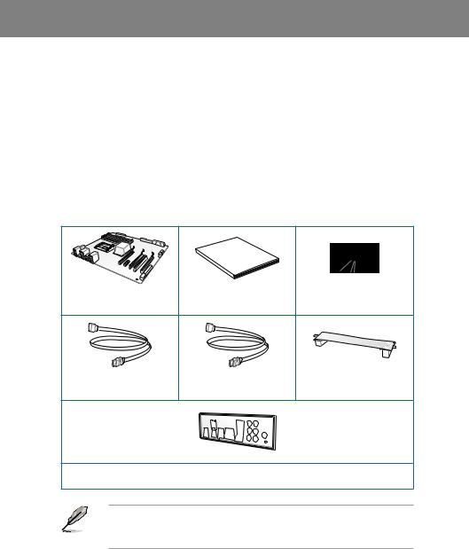
Chapter 1
|
Chapter 1: |
Product introduction |
1.1Welcome!
Thank you for buying an ASUS® P8Z77-V LE PLUS motherboard!
The motherboard delivers a host of new features and latest technologies, making it another standout in the long line of ASUS quality motherboards!
Before you start installing the motherboard, and hardware devices on it, check the items in your package with the list below.
1.2Package contents
Check your motherboard package for the following items.
Chapter 1
Manual
User
|
ASUS P8Z77-V LE PLUS |
User guide |
Support DVD |
|
|
motherboard |
|||
|
2 x Serial ATA 6.0 Gb/s cables |
2 x Serial ATA 3.0 Gb/s cables |
1 x ASUS SLI™ bridge |
|
|
connector |
|||
1 x ASUS I/O Shield
• If any of the above items is damaged or missing, contact your retailer.
• The illustrated items above are for reference only.Actual product specifications may vary with different models.

1 Chapter
1.3Special features
1.3.1Product highlights
LGA1155 socket for Intel® 3rd / 2nd Generation Core™ i7 / Core™ i5 / Core™ i3 / Pentium® / Celeron® Processors
This motherboard supports Intel® 3rd / 2nd generation Core™ i7 / i5 / i3 / Pentium® / Celeron® processors in the LGA1155 package, with iGPU, memory and PCI Express controllers integrated to support onboard graphics output with dedicated chipsets, 2-channel (4 DIMMs) DDR3 memory and 16 PCI Express 3.0/2.0 lanes. This provides great graphics performance. Intel® 3rd / 2nd generation Core™ i7 / i5 / i3 / Pentium® / Celeron® processors are among the most powerful and energy efficient CPUs in the world.
Intel® Z77 Express Chipset
The Intel® Z77 Express Chipset is a single-chipset design to support socket 1155 Intel® 3rd/ 2nd generation Core™ i7 / i5 / i3 / Pentium® / Celeron® processors. It provides improved performance by utilizing serial point-to-point links, allowing increased bandwidth and stability.
Additionally, Z77 chipset provides 4 USB 3.0 ports for 10 times faster data retrieval speed. Moreover, Intel® Z77 Express Chipset can also enable iGPU function, letting users enjoy the latest Intel® integrated graphic performance.
Dual-Channel DDR3 2400(O.C.) / 2200(O.C.) / 2133(O.C.) / 1866(O.C.) / 1600 / 1333 / 1066 Support*
The motherboard supports DDR3 memory that features data transfer rates of DDR3 2400(O.
C.) / 2200(O.C.) / 2133(O.C.) / 1866 / 1600/ 1333 / 1066 MHz to meet the higher bandwidth requirements of the latest 3D graphics, multimedia, and Internet applications. The dualchannel DDR3 architecture enlarges the bandwidth of your system memory to boost system performance.
Complete USB 3.0 Integration
ASUS facilitates strategic USB 3.0 accessibility for both the front and rear panel — 6 USB 3.0 ports in total. Experience the latest plug & play connectivity at speeds up to 10 times faster than USB 2.0. The P8Z77-V LE PLUS affords greater convenience to high speed connectivity.
Quad-GPU SLI™ and Quad-GPU CrossFireX™ Support
Flexible Multi-GPU Solutions, Your Weapon of Choice!
P8Z77-V LE PLUS brings you the multi-GPU choice of either SLI™ or CrossFireX. The motherboard features the most powerful Intel® Z77 platform to optimize PCIe allocation in multiple GPU configurations. Expect a brand-new gaming style you’ve never experienced before!
S/PDIF out connector at the back I/O
This motherboard provides convenient connectivity to external home theater audio systems via the optical S/PDIF (SONY-PHILIPS Digital Interface) out connecor at the back I/O. The S/PDIF transfers digital audio without converting it to analog format and keeps the best signal quality.
|
1-2 |
Chapter 1: Product Introduction |

Intel® Smart Response Technology
SSD Speed with HDD Capacity
Intel® Smart Response Technology boosts overall system performance. It uses an installed fast SSD (min 18.6GB available capacity required) as a cache for frequently accessed data.
Key benefits include reduced load and wait times, and lower power consumption through the elimination of unnecessary hard drive spin. This technology combines SSD performance with hard drive capacity, operating up to 4X faster than a hard drive-only system, and an important part of Green ASUS eco-friendly computing.
*Intel® Smart Response Technology is supported by 3rd / 2nd generation Intel® Core™ processor family on Windows® 7™ operating systems.
**Operating systems must be installed on the HDD to launch Intel® Smart Response Technology. The capacity of the SSD is reserved for caching function.
Intel® Smart Connect Technology
Your computer can receive web updates with fresh content for selected applications, even when the system is in sleep mode. This means less time waiting for applications to update and sync with the cloud, leading to a more efficient computing experience.
Intel® Rapid Start Technology
Allows your computer to quickly resume from a low-power hibernate state in seconds. Saving your system memory to the designed SSD, it provides your computer a faster wake-up response time, while still keeping the energy use low.
Extra SATA 6Gb/s Support
The Intel® Z77 Express chipset natively supports the next-generation Serial ATA (SATA) interface, delivering up to 6.0 Gb/s data transfer. ASUS provides extra SATA 6.0 Gb/s ports with enhanced scalability, faster data retrieval, and double the bandwidth of current bus systems.
PCI Express® 3.0
PCI Express® 3.0 (PCIe 3.0) is the latest PCI Express bus standard with improved encoding schemes that provide twice the performance of the current PCIe 2.0. The total bandwidth for a x16 link reaches a maximum of 32GB/s, double the 16GB/s of PCIe 2.0 (in x16 mode). As such, PCIe 3.0 provides users unprecedented data speeds, combined with the convenience and seamless transition offered by complete backward compatibility with PCIe 1.0 and PCIe 2.0 devices. PCIe 3.0 will become a must-have feature for users who wish to improve and optimize graphic performance, as well as have the latest technology available to them.
* PCIe 3.0 speed is supported by Intel® 3rd generation CoreTM processors.
Gigabit LAN solution
The onboard LAN controller is a highly integrated Gb LAN controller. It is enhanced with an
ACPI management function to provide efficient power management for advanced operating systems.
Chapter 1

1 Chapter
8-channel high definition audio
The onboard 8-channel HD audio (High DefinitionAudio, previously codenamedAzalia) CODEC enables high-quality 192KHz/24-bit audio output and jack-detect feature that automatically detects and identifies what types of peripherals are plugged into the audio I/O jacks and notifies users of inappropriate connection, which means there will be no more confusion of Line-in, Line-out, and Mic jacks.
100% All High-quality Conductive Polymer Capacitors
This motherboard uses all high-quality conductive polymer capacitors for durability, improved lifespan, and enhanced thermal capacity.
1.3.2Dual Intelligent Processors 3 with Smart DIGI+
The world’s first Dual Intelligent Processors fromASUS pioneered twin onboard chips — TPU
(TurboV Processing Unit) and EPU (Energy Processing Unit). Dual Intelligent Processors 3 builds on that foundation with new SMART DIGI+ power control, which includes multiple digital voltage controllers, allowing ultra-precise tuning for the CPU, iGPU and DRAM. It’s upgraded with one-click extreme performance optimization and selectable CPU wattage levels, offering easier power control and better power savings with the user-friendly AI Suite II utility.
Smart DIGI+ Technology
Get incredible performance increases with TPU and the all-new SMART DIGI+.
Up to 85% CPU O.C. Performance Boost
Always at the forefront of digital power design, ASUS propels you into the future standard of power management by SMART DIGI+ Technology, which works with the TPU (TurboV Processing Unit) to give an exceptional increase in CPU overclocking performance. When combined, you can adjust CPU ratios manually in the TPU and enable the all new SMART DIGI+ Key by a single click to see an extreme boost in TPU frequency up to 85%.
CPU Power Wattage cut in half!
SMART DIG+ Technology also includes the Smart CPU Power Level profile, which reduces CPU power consumption to a specific indicated wattage with a single click, creating a cooler and quieter PC. With the support for the next generation Intel® VRD 12.5 power design, ASUS once again leaps to the future of innovation.
TPU
The Ultimate Turbo Processor
Unleash your performance with ASUS’ simple onboard switch or AI Suite II utility. The TPU chip offers precise voltage control and advanced monitoring through Auto Tuning and TurboV functions.Auto tuning offers a user friendly way to automatically optimize the system for fast, yet stable clock speeds, while TurboV enables unlimited freedom to adjust CPU frequencies and ratios for optimized performance in diverse situations.
|
1-4 |
Chapter 1: Product Introduction |

EPU
Energy Efficiency All Around
Tap into the world’s first real-time PC power saving chip through a simple onboard switch or AI Suite II utility. Get total system-wide energy optimization by automatically detecting current
PC loadings and intelligently moderating power consumption. This also reduces fan noise and extends component longevity.
ASUS TurboV
Easy, Real-Time O.C. Tunings
Feel the adrenaline rush of real-time OC-now a reality with the ASUS TurboV. This easy OC tool allows you to overclock without exiting or rebooting the OS; and its user-friendly interface makes overclock with just a few clicks away. Moreover, theASUS OC profiles in TurboV provides the best O.C. settings in different scenarios.
Auto Tuning
Auto Tuning is an intelligent tool that automates overclocking to achieve a total system level up. This tool also provides stability testing. Even O.C. beginners can achieve extreme yet stable overclocking results with Auto Tuning!
GPU Boost
Go to the Limit with iGPU Level Up!
GPU Boost accelerates the integrated GPU for extreme graphics performance. The userfriendly interface facilitates flexible frequency adjustments. It easily delivers stable systemlevel upgrades for every use.
1.3.3ASUS Exclusive Features
USB 3.0 Boost
Faster USB 3.0 Transmission with UASP
New ASUS USB 3.0 Boost technology supports UASP (USB Attached SCSI Protocol), the latest USB 3.0 standard. With USB 3.0 Boost technology, a USB device’s transmission speed is significantly increased up to 170%, adding to an already impressive fast USB 3.0 transfer speed. ASUS software automatically accelerates data speeds for compatible USB 3.0 peripherals without the need for any user interaction.
USB BIOS Flashback
Easy, Worry-free USB BIOS Flashback
A truly revolutionary hardware-based BIOS update solution. USB BIOS Flashback offers the most convenient way to update the BIOS! It allows users to update new UEFI BIOS versions even without hardware such as a CPU or a DRAM installed into the motherboard.
Just plug in a USB flash drive containing the BIOS file, and press the BIOS Flashback button for 3 seconds with the power supply connected. The UEFI BIOS then automatically updates without requiring further interaction. With its new complementary Windows® application, users can regularly check for UEFI BIOS updates, and downloads the latest BIOS automatically. Hassle-free updating for the ultimate convenience!
Chapter 1

1 Chapter
Network iControl
Real-time Network Bandwidth Control
With a single-click on/off button, the application currently in use has its data and network bandwidth prioritized over other programs. Moreover, you can prioritize your favorite software easily by configuring profiles through the intuitive user interface. Within the profile, the programs can be pre-scheduled to run in a specific time period to avoid network congestion and long-waits on downloads. Auto PPPoE network connection provides a one-step setup. Overall, it’s an intuitive network bandwidth control center.
MemOK!
Any Memory is A-OK!
MemOK! quickly ensures memory boot compatibility. This remarkable memory rescue tool requires a mere push of a button to patch memory issues. MemOK! determines fail-safe settings and dramatically improves your system boot success. Get your system up and running in no time!
USB Charger+
3X Faster Charging for All Smart Devices
With a dedicated onboard controller, quick-charge all your smart devices such as iProducts, smartphones, tablets, and more, all up to 3x faster, even when the PC is powered off, in sleep, or hibernation mode.
AI Suite II
One-stop Access to Innovative ASUS Features
With its user-friendly interface, ASUS AI Suite II consolidates all the exclusive ASUS features into one simple to use software package. It allows you to supervise overclocking, energy management, fan speed control, voltage and sensor readings. This all-in-one software offers diverse and ease to use functions, with no need to switch back and forth between different utilities.
ASUS MyLogo2™
This feature allows you to convert your favorite photo into a 256-color boot logo for a more colorful and vivid image on your screen.
Precision Tweaker 2
Allows you to fine-tune the vCore voltage in 0.005V steps and DRAM voltage in 0.00625V steps to achieve the most precise setting for the ultimate overclocking configuration.
C.P.R. (CPU Parameter Recall)
The BIOS C.P.R. feature automatically restores the CPU default settings when the system hangs due to overclocking failure. C.P.R. eliminates the need to open the system chassis and clear the RTC data. Simply shut down and reboot the system, and the BIOS automatically restores the CPU parameters to their default settings.
|
1-6 |
Chapter 1: Product Introduction |

1.3.4ASUS Quiet Thermal Solutions
ASUS Quiet Thermal solution makes system more stable and enhances the overclocking capability.
Fan Xpert+
ASUS Fan Xpert+ intelligently allows you to adjust the CPU fan and chassis fan speeds according to different ambient temperatures caused by different climate conditions in different geographic regions and your PC’s loading. The built-in variety of useful profiles offer flexible controls of fan speed to achieve a quiet and cool environment.
Fanless Design: stylish heatsink solution
The stylish heatsink features a 0-dB thermal solution that offers users a noiseless PC environment. Not only the beautiful shape upgrades the visual enjoyment for motherboard users, but also the heatsink design lowers the temperature of the chipset and power phase area through high efficient heat-exchange. Combined with usability and aesthetics, theASUS stylish heatsink will give users an extremely silent and cooling experience with the elegant appearance!
1.3.5ASUS EZ DIY
ASUS UEFI BIOS (EZ Mode)
Flexible and Easy BIOS Interface
Media-renowned UEFI BIOS offers the first mouse-controlled graphical BIOS designed with selectable modes and native support for hard drives over 2.2 TB. Users can also drag and drop boot priorities with the exclusive EZ Mode, while Advanced Mode offers inticrate settings.
New upgrade! Quick and easy information for enhanced system control
—F12 BIOS snapshot hotkey
—F3 Shortcut for most accessed information
—ASUS DRAM SPD (Serial Presence Detect) information detecting faulty DIMMs, and helping with difficult POST situations.
ASUS EZ-Flash 2
ASUS EZ Flash 2 is a user-friendly utility that allows you to update the BIOS without using a bootable floppy disk or an OS-based utility.
ASUS Q-Slot
ASUS Q-Slot is designed to speed up and simplify the DIY process to enhance your DIY experience.
CrashFree BIOS 3
Simply restore corrupted BIOS data from USB flash disk
The ASUS CrashFree BIOS 3 allows users to restore corrupted BIOS data from a USB flash disk containing the BIOS file. This utility saves users the cost and hassle of buying a replacement BIOS chip.
Chapter 1

1 Chapter
1.3.6Other special features
LucidLogix Virtu MVP
LucidLogix Virtu MVP featuring HyperFormance™ Technology boosts your discrete graphics card up to 30% beyond its original performance. Designed for Intel® processor graphics and Windows® 7 PCs, it perfectly combines the performance of discrete graphic cards with fast computing iGPU. Also, with newly designed Virtual Sync, users can enjoy a smoother gaming experience by eliminating tearing artifacts. LucidLogix Virtu MVP can also dynamically assign tasks to the best available graphics resource, based on power, performance, and system load. This allows users to fully utilize 3x faster video conversion with Intel® Quick Sync Video technology while retaining high-end 3D rendering and gaming performance, provided by both NVIDIA and AMD graphic cards. When the discrete graphic cards are not required, it puts the power use down to zero, making the system more environmentally friendly. For users searching for perfection, LucidLogix Virtu MVP provides great graphical performance, and best flexibility and efficiency.
*LucidLogix Virtu MVP supports Windows® 7 operating system.
**Intel® Quick Sync Video feature is supported by 3rd /2nd generation Intel® Core™ processor family.
DisplayPort 1.1a Support
DisplayPort is a digital display interface standard that delivers up to 10.8 Gbps of bandwidth over standard cables, providing billions of colors and bi-directional communications, thus enabling the fastest refresh rates, and the highest resolution digital display through a single cable. Also, it supports HDCP copy protection for Blu-ray discs. Simply output 3D signals through the connected DisplayPort 1.1a cable with your 3D display, then you can sit back and enjoy a perfect 3D animation experience.
HDMI Support
Enjoy Full HD 1080p Multimedia Home-Theater Entertainment
High Definition Multimedia Surface (HDMI) is a set of digital video standards that delivers mulit-channel audio and uncompressed digital video for full HD 1080p visuals through a single cable. Supporting HDCP copy protection such as HD DVD and blu-ray discs, HDMI provides you with the highest quality home theater experience.
ErP ready
The motherboard is European Union´s Energy-related Products (ErP) ready, and ErP requires products to meet certain energy efficiency requirements in regards to energy consumptions. This is in line with ASUS vision of creating environment-friendly and energyefficient products through product design and innovation to reduce carbon footprint of the product and thus mitigate environmental impacts.
|
1-8 |
Chapter 1: Product Introduction |
![]()
Chapter 2
|
Chapter 2: |
Hardware information |
2.1Before you proceed
Take note of the following precautions before you install motherboard components or change any motherboard settings.
•Unplug the power cord from the wall socket before touching any component.
• Before handling components, use a grounded wrist strap or touch a safely grounded object or a metal object, such as the power supply case, to avoid damaging them due to static electricity.
•Hold components by the edges to avoid touching the ICs on them.
•Whenever you uninstall any component, place it on a grounded antistatic pad or in the bag that came with the component.
•Before you install or remove any component, ensure that the ATX power supply is switched off or the power cord is detached from the power supply. Failure to do so may cause severe damage to the motherboard, peripherals, or components.
Chapter 2

2 Chapter
2.2Motherboard overview
2.2.1Motherboard layout
|
1 |
2 |
3 |
4 |
5 |
1 |
6 |
7 |
8 |
24.4cm(9.6in)
|
EPU |
TPU |
||||||||||||||
|
KB_USB12 |
EPU_LED |
TPU_LED |
CPU_FAN CHA_FAN2 |
||||||||||||
|
EATX12V |
DIGI+ |
||||||||||||||
|
VRM |
|||||||||||||||
|
SPDIFO |
|||||||||||||||
|
_HDMI |
|||||||||||||||
|
_DP |
1 |
||||||||||||||
|
ASM |
|||||||||||||||
|
1442 |
|||||||||||||||
|
VGADVI |
module)pin |
module)pin |
module)pin |
module)pin |
9 |
||||||||||
|
MemOK! |
10 |
||||||||||||||
|
DRAM_LED |
|||||||||||||||
|
— |
— |
— |
— |
||||||||||||
|
LGA1155 |
240 |
240 |
240 |
240 |
|||||||||||
|
USB3_12 |
A1(64bit, |
A2(64bit, |
B1(64bit, |
B2(64bit, |
|||||||||||
|
ESATA6G |
|||||||||||||||
|
_ |
_ |
_ |
_ |
EATXPWR |
2 |
||||||||||
|
DDR3DIMM |
DDR3DIMM |
DDR3DIMM |
DDR3DIMM |
||||||||||||
|
CHA_FAN3 |
|||||||||||||||
|
LAN_USB3_E12 |
30.5cm(12.0in) |
||||||||||||||
|
AUDIO |
|||||||||||||||
|
CHA_FAN1 |
|||||||||||||||
|
USB3_34 |
|||||||||||||||
|
PCIEX1_1 |
Lithium Cell |
||||||||||||||
|
CMOS Power |
|||||||||||||||
|
RTL |
P8Z77-V LE PLUS |
11 |
|||||||||||||
|
8111F |
|||||||||||||||
|
PCIEX16_1 |
|||||||||||||||
|
ASM |
PCIEX1_2 |
Marvell® PCIe SATA |
|||||||||||||
|
1042 |
6.0Gb/s controller |
||||||||||||||
|
Intel® |
12 |
||||||||||||||
|
PCI1 |
Z77 |
||||||||||||||
|
1 2 |
|||||||||||||||
|
13 |
|||||||||||||||
|
SATA6G |
SATA6G |
||||||||||||||
|
Super |
PCIEX16_2 |
ASM |
1 2 |
||||||||||||
|
ASM |
AI 1314 |
SATA3G3 |
SATA3G4 |
14 |
|||||||||||
|
I/O |
|||||||||||||||
|
PCI2 |
1083 |
64Mb |
TPU |
SATA3G |
SATA3G |
||||||||||
|
BIOS |
15 |
||||||||||||||
|
889 |
|||||||||||||||
|
ALC |
|||||||||||||||
|
PCIEX16_3 |
SATA6G_E1 |
SB_PWR |
|||||||||||||
|
FLBK_LED |
|||||||||||||||
|
SPDIF_OUT |
COM1 |
USB910 |
USB78 |
USB56 |
USB34 |
BIOS_FLBK |
CLRTC |
||||||||
|
AAFP |
PANEL |
||||||||||||||
|
23 |
22 |
21 |
20 |
19 |
18 |
17 |
16 |
Refer to 2.2.8 Connectors and 2.3.10 Rear panel connection for more information about rear panel connectors and internal connectors.
|
2-2 |
Chapter 2: Hardware information |

Layout contents
|
Connectors/Jumpers/Slots |
Page |
|
|
1. |
CPU and chassis fan connectors (4-pin CPU_FAN, 4-pin CHA_FAN1/2/3) |
2-25 |
|
2. |
ATX power connectors (24-pin EATXPWR, 8-pin EATX12V) |
2-27 |
|
3. |
EPU LED (EPU_LED) |
2-21 |
|
4. |
EPU switch |
2-18 |
|
5. |
TPU switch |
2-17 |
|
6. |
TPU LED (TPU_LED) |
2-21 |
|
7. |
Intel® CPU socket |
2-4 |
|
8. |
DDR3 DIMM sockets |
2-5 |
|
9. |
DRAM LED |
2-20 |
|
10. |
MemOK! button |
2-16 |
|
11. |
USB 3.0 connector (20-1 pin USB3_34) |
2-26 |
|
12. |
Marvell® Serial ATA 6.0 Gb/s connectors (7-pin SATA 6G_E1 [navy blue]) |
2-27 |
|
13. |
Intel® Z77 Serial ATA 6.0 Gb/s connectors (7-pin SATA6G_1/2 [gray]) |
2-22 |
|
14. |
Intel® Z77 Serial ATA 3.0 Gb/s connectors (7-pin SATA3G_1~4 [blue]) |
2-23 |
|
15. |
Onboard LED (SB_PWR) |
2-20 |
|
16. |
BIOS Flashback LED (FLBK_LED) |
2-21 |
|
17. |
Clear RTC RAM (3-pin CLRTC) |
2-15 |
|
18. |
System panel connector (20-8 pin PANEL) |
2-28 |
|
19. |
BIOS Flashback button (BIOS_FLBK) |
2-19 |
|
20. |
USB 2.0 connectors (10-1 pin USB3~10) |
2-24 |
|
21. |
Serial port connectors (10-1 pin COM1) |
2-26 |
|
22. |
Front panel audio connector (10-1 pin AAFP) |
2-24 |
|
23. |
Digital audio connector (4-1 pin SPDIF_OUT) |
2-25 |
Chapter 2
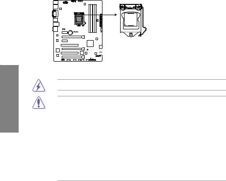
2.2.2Central Processing Unit (CPU)
The motherboard comes with a surface mount LGA1155 socket designed for the Intel® 3rd / 2nd Generation Core™ i7/ i5/ i3/ Pentium® / Celeron® Processors.
2 Chapter
P8Z77-V LE PLUS
P8Z77-V LE PLUS CPU socket LGA1155
Ensure that all power cables are unplugged before installing the CPU.
•The LGA1156 CPU is incompatible with the LGA1155 socket. DO NOT install a LGA1156 CPU on the LGA1155 socket.
•Upon purchase of the motherboard, ensure that the PnP cap is on the socket and the socket contacts are not bent. Contact your retailer immediately if the PnP cap is missing, or if you see any damage to the PnP cap/socket contacts/motherboard components. ASUS will shoulder the cost of repair only if the damage is shipment/ transit-related.
•Keep the cap after installing the motherboard. ASUS will process Return Merchandise
Authorization (RMA) requests only if the motherboard comes with the cap on the
LGA1155 socket.
•The product warranty does not cover damage to the socket contacts resulting from incorrect CPU installation/removal, or misplacement/loss/incorrect removal of the PnP cap.
|
2-4 |
Chapter 2: Hardware information |
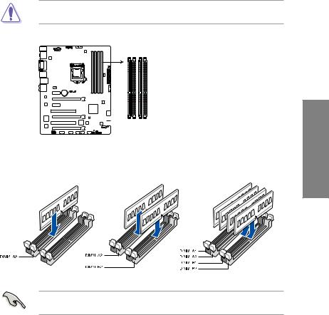
2.2.3System memory
The motherboard comes with four Double Data Rate 3 (DDR3) Dual Inline Memory Modules (DIMM) sockets.
A DDR3 module is notched differently from a DDR or DDR2 module. DO NOT install a DDR or DDR2 memory module to the DDR3 slot.
|
DIMM A1 |
DIMM A2 |
DIMM B1 |
DIMM B2 |
|
P8Z77-V LE PLUS |
P8Z77-V LE PLUS 240-pin DDR3 DIMM sockets
Recommended memory configurations
Chapter 2
We recommend that you install the memory modules from the blue slots for better overclocking capability.
Memory configurations
You may install 1GB, 2GB, 4GB and 8GB unbuffered non ECC DDR3 DIMMs into the DIMM sockets.
• You may install varying memory sizes in ChannelAand Channel B. The system maps the total size of the lower-sized channel for the dual-channel configuration.Any excess memory from the higher-sized channel is then mapped for single-channel operation.
2 Chapter
•According to Intel® CPU spec, DIMM voltage below 1.65V is recommended to protect the CPU.
•Always install DIMMs with the same CAS latency. For optimum compatibility, we recommend that you obtain memory modules from the same vendor.
•Due to the memory address limitation on 32-bit Windows OS, when you install 4GB or more memory on the motherboard, the actual usable memory for the OS can be about 3GB or less. For effective use of memory, we recommend that you do any of the following:
—Use a maximum of 3GB system memory if you are using a 32-bit Windows OS.
—Install a 64-bit Windows OS when you want to install 4GB or more on the motherboard.
For more details, refer to the Microsoft® support site at http://support.microsoft.com/kb/929605/en-us.
•This motherboard does not support DIMMs made up of 512Mb (64MB) chips or less (Memory chip capacity counts in Megabit, 8 Megabit/Mb = 1 Megabyte/MB).
•The default memory operation frequency is dependent on its Serial Presence Detect (SPD), which is the standard way of accessing information from a memory module. Under the default state, some memory modules for overclocking may operate at a lower frequency than the vendor-marked value. To operate at the vendor-marked
or at a higher frequency, refer to section 3.4 Ai Tweaker menu for manual memory frequency adjustment.
•For system stability, use a more efficient memory cooling system to support a full memory load (4 DIMMs) or overclocking condition.
Visit the ASUS website for the latest QVL.
P8Z77-V LE PLUS Motherboard Qualified Vendors Lists (QVL)
DDR3 2400MHz capability
|
Vendors |
Part No. |
Size |
SS/ |
Chip |
Chip |
Timing |
Voltage |
DIMM socket support |
|
|
DS |
Brand |
NO. |
(Optional) |
||||||
|
1 DIMM |
2 DIMMs 4 DIMMs |
||||||||
|
Transcend |
TX2400KLU-4GK (381850)(XMP) |
4GB(2x 2GB) |
SS |
— |
— |
9 |
1.65V |
• |
• |
*The 2400MHz memory modules above are supported on Intel® 3rd generation processors by this motherboard; however, the actual frequency support varied depending on the O.C. margin of the installed CPU.
**Due to Intel 2nd generation processors’ behavior, DDR3 2200 (and above)/2000/1800 MHz memory modules run at DDR3 2133/1866/1600 MHz frequency as default.
|
2-6 |
Chapter 2: Hardware information |

P8Z77-V LE PLUS Motherboard Qualified Vendors Lists (QVL)
DDR3 2250MHz capability
|
Vendors |
Part No. |
Size |
SS/ |
Chip |
Chip |
Timing |
Voltage |
DIMM socket support (Optional) |
||
|
DS |
Brand |
NO. |
1 DIMM |
2 DIMMs |
4 DIMMs |
|||||
|
Kingston |
KHX2250C9D3T1K2/4GX(XMP) |
4GB(2x 2GB) |
DS |
— |
— |
— |
1.65V |
• |
• |
• |
*The memory modules in 2250MHz and above are supported on Intel® 3rd generation processors by this motherboard; however, the actual frequency support varies depending on the O.C. margin of the installed CPU.
**Due to Intel 2nd generation processors’ behavior, DDR3 2200 (and above)/2000/1800 MHz memory modules run at DDR3 2133/1866/1600 MHz frequency as default.
P8Z77-V LE PLUS Motherboard Qualified Vendors Lists (QVL)
DDR3 2200MHz capability
|
Vendors |
Part No. |
Size |
SS/ |
Chip |
Chip |
Timing |
Voltage |
DIMM socket support (Optional) |
|
DS |
Brand |
NO. |
1 DIMM 2 DIMMs 4 DIMMs |
|||||
|
G.SKILL |
F3-17600CL8D-4GBPS(XMP) |
4GB(2x 2GB) |
DS |
— |
— |
8-8-8-24 |
1.65V |
• |
|
KINGMAX |
FLKE85F-B8KJAFEIH(XMP) |
4GB(2x 2GB) |
DS |
— |
— |
— |
1.5V-1.7V |
• |
*The memory modules in 2200MHz and above are supported on Intel® 3rd generation processors by this motherboard; however, the actual frequency support varies depending on the O.C. margin of the installed CPU.
**Due to Intel 2nd generation processors’ behavior, DDR3 2200 (and above)/2000/1800 MHz memory modules run at DDR3 2133/1866/1600 MHz frequency as default.
P8Z77-V LE PLUS Motherboard Qualified Vendors Lists (QVL)
DDR3 2133MHz capability
|
Vendors |
Part No. |
Size |
SS/ |
Chip |
Chip |
Timing |
Voltage |
DIMM socket support (Optional) |
||
|
DS |
Brand |
NO. |
1 DIMM |
2 DIMMs |
4 DIMMs |
|||||
|
A-DATA |
AX3U2133GC2G9B-DG2(XMP) |
2GB |
SS |
— |
— |
9-11-9-27 |
1.55~1.75V |
• |
||
|
CORSAIR |
CMT4GX3M2A2133C9(XMP) |
4GB(2x 2GB) |
DS |
— |
— |
9-10-9-24 |
1.65V |
• |
||
|
CORSAIR |
CMT4GX3M2B2133C9(XMP) |
4GB(2x 2GB) |
DS |
— |
— |
9-10-9-27 |
1.50V |
• |
• |
|
|
GEIL |
GE34GB2133C9DC(XMP) |
2GB |
DS |
— |
— |
9-9-9-28 |
1.65V |
• |
• |
|
|
GEIL |
GU34GB2133C9DC(XMP) |
4GB(2 x 2GB) |
DS |
— |
— |
9-9-9-28 |
1.65V |
• |
• |
• |
|
KINGSTON |
KHX2133C9AD3T1K2/4GX(XMP) |
4GB(2x 2GB ) |
DS |
— |
— |
— |
1.65V |
• |
• |
• |
|
KINGSTON |
KHX2133C9AD3X2K2/4GX(XMP) |
4GB(2 x 2GB) |
DS |
— |
— |
9-11-9-27 |
1.65V |
• |
• |
• |
|
KINGSTON |
KHX2133C9AD3T1K4/8GX(XMP) |
8GB(4 x 2GB) |
DS |
— |
— |
9-11-9-27 |
1.65V |
• |
• |
• |
|
KINGSTON |
KHX2133C9AD3T1FK4/8GX(XMP) |
8GB(4x 2GB) |
DS |
— |
— |
— |
1.65V |
• |
• |
• |
P8Z77-V LE PLUS Motherboard Qualified Vendors Lists (QVL)
DDR3 2000MHz capability
|
Vendors |
Part No. |
Size |
SS/ |
Chip |
Chip |
Timing |
Voltage |
DIMM socket support (Optional) |
||
|
DS |
Brand |
NO. |
1 DIMM |
2 DIMMs |
4 DIMMs |
|||||
|
Apacer |
78.AAGD5.9KD(XMP) |
6GB(3 x 2GB) |
DS |
— |
— |
9-9-9-27 |
1.65V |
• |
• |
• |
|
CORSAIR |
CMZ4GX3M2A2000C10(XMP) |
4GB(2 x 2GB) |
SS |
— |
— |
10-10-10-27 |
1.50V |
• |
• |
• |
|
CORSAIR |
CMT6GX3M3A2000C8(XMP) |
6GB(3 x 2GB) |
DS |
— |
— |
8-9-8-24 |
1.65V |
• |
• |
|
|
G.SKILL |
F3-16000CL9D-4GBFLS(XMP) |
4GB(2 x 2GB) |
DS |
— |
— |
9-9-9-24 |
1.65V |
• |
• |
• |
|
G.SKILL |
F3-16000CL9D-4GBTD(XMP) |
4GB(2 x 2GB) |
DS |
— |
— |
9-9-9-27 |
1.65V |
• |
• |
• |
|
G.SKILL |
F3-16000CL6T-6GBPIS(XMP) |
6GB(3x 2GB ) |
DS |
— |
— |
6-9-6-24 |
1.65V |
• |
• |
|
|
KINGSTON |
KHX2000C9AD3T1K2/ |
4GB(2x 2GB ) |
DS |
— |
— |
— |
1.65V |
• |
• |
• |
|
4GX(XMP) |
||||||||||
|
KINGSTON |
KHX2000C9AD3W1K2/ |
4GB(2x 2GB ) |
DS |
— |
— |
— |
1.65V |
• |
• |
|
|
4GX(XMP) |
||||||||||
|
KINGSTON |
KHX2000C9AD3T1K2/ |
4GB(2 x 2GB) |
DS |
— |
— |
9 |
1.65V |
• |
• |
• |
|
4GX(XMP) |
||||||||||
|
KINGSTON |
KHX2000C9AD3W1K3/ |
6GB(3x 2GB ) |
DS |
— |
— |
— |
1.65V |
• |
• |
|
|
6GX(XMP) |
||||||||||
|
KINGSTON |
KHX2000C9AD3T1K3/ |
6GB(3x 2GB ) |
DS |
— |
— |
— |
1.65V |
• |
• |
|
|
6GX(XMP) |
||||||||||
|
Transcend |
TX2000KLN-8GK(XMP) |
8GB(2 x 4GB) |
DS |
— |
— |
— |
1.6V |
• |
• |
• |
Chapter 2

2 Chapter
P8Z77-V LE PLUS Motherboard Qualified Vendors Lists (QVL)
DDR31866MHz capability
|
Vendors |
Part No. |
Size |
SS/ |
Chip |
Chip |
Timing |
Voltage |
DIMM socket support (Optional) |
||
|
DS |
Brand |
NO. |
1 DIMM |
2 DIMMs |
4 DIMMs |
|||||
|
CORSAIR |
CMT4GX3M2A1866C9(XMP) |
4GB(2 x 2GB) |
DS |
— |
— |
9-9-9-24 |
1.65V |
• |
• |
• |
|
CORSAIR |
CMT6GX3MA1866C9(XMP) |
6GB(3 x 2GB) |
DS |
— |
— |
9-9-9-24 |
1.65V |
• |
• |
|
|
CORSAIR |
CMZ8GX3M2A1866C9(XMP) |
8GB(2 x 4GB) |
DS |
— |
— |
9-10-9-27 |
1.50V |
• |
• |
• |
|
G.SKILL |
F3-14900CL9D- |
8GB(2 x 4GB) |
DS |
— |
— |
9-10-9-28 |
1.5V |
• |
• |
• |
|
8GBXL(XMP) |
||||||||||
|
G.SKILL |
F3-14900CL9Q- |
8GB(2GB x 4) |
DS |
— |
— |
9-9-9-24 |
1.6V |
• |
• |
• |
|
8GBXL(XMP) |
||||||||||
|
KINGSTON |
KHX1866C9D3T1K3/ |
3GB(3 x 1GB) |
SS |
— |
— |
— |
1.65V |
• |
• |
• |
|
3GX(XMP) |
||||||||||
|
KINGSTON |
KHX1866C9D3T1K3/ |
6GB(3 x 2GB) |
DS |
— |
— |
— |
1.65V |
• |
• |
• |
|
6GX(XMP) |
P8Z77-V LE PLUS Motherboard Qualified Vendors Lists (QVL)
DDR3 1600MHz capability
|
Vendors |
Paart No. |
Size |
SS/ |
Chip |
Chip NO. |
Timing |
Voltage |
DIMM socket support |
||
|
DS |
Brand |
(Optional) |
||||||||
|
1 DIMM |
2 DIMMs |
4 DIMMs |
||||||||
|
A-DATA |
AM2U16BC2P1 |
2GB |
SS |
A-DATA |
3CCD-150 |
— |
— |
• |
• |
• |
|
9A EL1126T |
||||||||||
|
A-DATA |
AD31600E001GM(O)U3K |
3GB(3 x 1GB) |
SS |
— |
— |
8-8-8-24 1.65V- |
• |
• |
||
|
1.85V |
||||||||||
|
A-DATA |
AM2U16BC4P2 |
4GB |
DS |
A-DATA |
3CCD-150 |
— |
— |
• |
• |
• |
|
9A EL1126T |
||||||||||
|
A-DATA |
AX3U1600GC4G9-2G(XMP) |
8GB(2 x 4GB) |
DS |
— |
— |
9-9-9-24 1.55V- |
• |
• |
• |
|
|
1.75V |
||||||||||
|
A-DATA |
AX3U1600XC4G79-2X(XMP) |
8GB(2 x 4GB) |
DS |
— |
— |
7-9-7-21 1.55V- |
• |
• |
• |
|
|
1.75V |
||||||||||
|
CORSAIR |
TR3X3G1600C8D(XMP) |
3GB(3 x 1GB) |
SS |
— |
— |
8-8-8-24 |
1.65V |
• |
• |
|
|
CORSAIR |
CMD12GX3M6A1600C8(XMP) |
12GB(6x2GB) |
DS |
— |
— |
8-8-8-24 |
1.65V |
• |
• |
• |
|
CORSAIR |
CMP4GX3M2A1600C8(XMP) |
4GB(2 x 2GB) |
DS |
— |
— |
8-8-8-24 |
1.65V |
• |
• |
• |
|
CORSAIR |
CMP4GX3M2A1600C9(XMP) |
4GB(2 x 2GB) |
DS |
— |
— |
9-9-9-24 |
1.65V |
• |
• |
• |
|
CORSAIR |
CMP4GX3M2C1600C7(XMP) |
4GB(2 x 2GB) |
DS |
— |
— |
7-8-7-20 |
1.65V |
• |
• |
• |
|
CORSAIR |
CMX4GX3M2A1600C9(XMP) |
4GB(2 x 2GB) |
DS |
— |
— |
9-9-9-24 |
1.65V |
• |
• |
|
|
CORSAIR |
CMX4GX3M2A1600C9(XMP) |
4GB(2 x 2GB) |
DS |
— |
— |
9-9-9-24 |
1.65V |
• |
• |
• |
|
CORSAIR |
TR3X6G1600C8 G(XMP) |
6GB(3 x 2GB) |
DS |
— |
— |
8-8-8-24 |
1.65V |
• |
• |
• |
|
CORSAIR |
TR3X6G1600C8D G(XMP) |
6GB(3 x 2GB) |
DS |
— |
— |
8-8-8-24 |
1.65V |
• |
• |
• |
|
CORSAIR |
TR3X6G1600C9 G(XMP) |
6GB(3 x 2GB) |
DS |
— |
— |
9-9-9-24 |
1.65V |
• |
• |
• |
|
CORSAIR |
CMP8GX3M2A1600C9(XMP) |
8GB(2 x 4GB) |
DS |
— |
— |
9-9-9-24 |
1.65V |
• |
• |
• |
|
CORSAIR |
CMZ8GX3M2A1600C7R(XMP) |
8GB(2 x 4GB) |
DS |
— |
— |
7-8-7-20 |
1.50V |
• |
• |
• |
|
CORSAIR |
CMX8GX3M4A1600C9(XMP) |
8GB(4 x 2GB) |
DS |
— |
— |
9-9-9-24 |
1.65V |
• |
• |
• |
|
Crucial |
BL25664BN1608.16FF(XMP) |
6GB(3 x 2GB) |
DS |
— |
— |
— |
— |
• |
• |
• |
|
G.SKILL |
F3-12800CL9D-2GBNQ(XMP) |
2GB(2 x 1GB) |
SS |
— |
— |
9-9-9-24 |
1.5V |
• |
• |
• |
|
G.SKILL |
F3-12800CL7D-4GBRH(XMP) |
4GB(2 x 2GB) |
SS |
— |
— |
7-7-7-24 |
1.6V |
• |
• |
• |
|
G.SKILL |
F3-12800CL7D-4GBRM(XMP) |
4GB(2 x 2GB) |
DS |
— |
— |
7-8-7-24 |
1.6V |
• |
• |
• |
|
G.SKILL |
F3-12800CL8D-4GBRM(XMP) |
4GB(2 x 2GB) |
DS |
— |
— |
8-8-8-24 |
1.60V |
• |
• |
• |
|
G.SKILL |
F3-12800CL9D-4GBECO(XMP) |
4GB(2 x 2GB) |
DS |
— |
— |
9-9-9-24 |
XMP 1.35V |
• |
• |
• |
|
G.SKILL |
F3-12800CL9D-4GBRL(XMP) |
4GB(2 x 2GB) |
DS |
— |
— |
9-9-9-24 |
1.5V |
• |
• |
• |
|
G.SKILL |
F3-12800CL9T-6GBNQ(XMP) |
6GB(3 x 2GB) |
DS |
— |
— |
9-9-9-24 |
1.5V~1.6V |
• |
• |
• |
|
G.SKILL |
F3-12800CL7D-8GBRH(XMP) |
8GB(2 x 4GB) |
DS |
— |
— |
7-8-7-24 |
1.6V |
• |
• |
• |
|
G.SKILL |
F3-12800CL8D-8GBECO(XMP) |
8GB(2 x 4GB) |
DS |
— |
— |
8-8-8-24 |
XMP 1.35V |
• |
• |
• |
|
G.SKILL |
F3-12800CL9D-8GBRL(XMP) |
8GB(2 x 4GB) |
DS |
— |
— |
9-9-9-24 |
1.5V |
• |
• |
• |
|
GEIL |
GET316GB1600C9QC(XMP) |
16GB(4x |
DS |
— |
— |
9-9-9-28 |
1.6V |
• |
• |
• |
|
4GB) |
||||||||||
|
GEIL |
GV34GB1600C8DC(XMP) |
2GB |
DS |
— |
— |
8-8-8-28 |
1.6V |
• |
• |
• |
|
KINGMAX |
FLGD45F-B8MF7 MAEH(XMP) |
1GB |
SS |
— |
— |
7 |
— |
• |
• |
|
|
KINGMAX |
FLGE85F-B8KJ9A FEIS(XMP) |
2GB |
DS |
— |
— |
— |
— |
• |
• |
• |
|
KINGMAX |
FLGE85F-B8MF7 MEEH(XMP) |
2GB |
DS |
— |
— |
7 |
— |
• |
||
|
KINGSTON |
KHX1600C9D3P1K2/4G |
4GB(2 x 2GB) |
SS |
— |
— |
— |
1.5V |
• |
• |
• |
|
KINGSTON |
KHX1600C9D3K3/12GX(XMP) |
12GB(3x4GB) |
DS |
— |
— |
9-9-9-27 |
1.65V |
• |
• |
• |
(continued on the next page)
|
2-8 |
Chapter 2: Hardware information |

P8Z77-V LE PLUS Motherboard Qualified Vendors Lists (QVL)
DDR3 1600MHz capability
|
Vendors |
Paart No. |
Size |
SS/ |
Chip |
Chip NO. |
Timing |
Voltage |
DIMM socket support |
||
|
DS |
Brand |
(Optional) |
||||||||
|
1 DIMM |
2 DIMMs |
4 DIMMs |
||||||||
|
KINGSTON |
KHX1600C9D3T1BK3/ |
12GB(3x4GB) |
DS |
— |
— |
9-9-9-27 |
1.65V |
• |
• |
• |
|
12GX(XMP) |
||||||||||
|
KINGSTON |
KHX1600C9AD3/2G |
2GB |
DS |
— |
— |
— |
1.65V |
• |
• |
• |
|
KINGSTON |
KVR1600D3N11/2G-ES |
2GB |
DS |
KTC |
D1288JPN |
11-11- |
1.35V-1.5V |
• |
• |
• |
|
DPLD9U |
11-28 |
|||||||||
|
KINGSTON |
KHX1600C7D3K2/4GX(XMP) |
4GB(2x 2GB ) |
DS |
— |
— |
— |
1.65V |
• |
• |
• |
|
KINGSTON |
KHX1600C8D3K2/4GX(XMP) |
4GB(2 x 2GB) |
DS |
— |
— |
8 |
1.65V |
• |
• |
• |
|
KINGSTON |
KHX1600C8D3T1K2/4GX(XMP) |
4GB(2 x 2GB) |
DS |
— |
— |
8 |
1.65V |
• |
• |
• |
|
KINGSTON |
KHX1600C9D3K2/4GX(XMP) |
4GB(2 x 2GB) |
DS |
— |
— |
9 |
1.65V |
• |
• |
• |
|
KINGSTON |
KHX1600C9D3LK2/4GX(XMP) |
4GB(2 x 2GB) |
DS |
— |
— |
9 |
XMP 1.35V |
• |
• |
• |
|
KINGSTON |
KHX1600C9D3X2K2/4GX(XMP) |
4GB(2 x 2GB) |
DS |
— |
— |
9-9-9-27 |
1.65V |
• |
• |
• |
|
KINGSTON |
KHX1600C9D3T1K3/6GX(XMP) |
6GB(3x 2GB ) |
DS |
— |
— |
— |
1.65V |
• |
• |
• |
|
KINGSTON |
KHX1600C9D3K3/6GX(XMP) |
6GB(3 x 2GB) |
DS |
— |
— |
9 |
1.65V |
• |
• |
• |
|
KINGSTON |
KHX1600C9D3T1BK3/6GX |
6GB(3 x 2GB) |
DS |
— |
— |
9-9-9-27 |
1.65V |
• |
• |
• |
|
(XMP) |
||||||||||
|
KINGSTON |
KHX1600C9D3K2/8GX(XMP) |
8GB(2 x 4GB) |
DS |
— |
— |
9-9-9-27 |
1.65V |
• |
• |
• |
|
KINGSTON |
KHX1600C9D3P1K2/8G |
8GB(2 x 4GB) |
DS |
— |
— |
— |
1.5V |
• |
• |
• |
|
Super Talent |
WA160UX6G9 |
6GB(3 x 2GB) |
DS |
— |
— |
9 |
— |
• |
• |
|
|
Transcend |
JM1600KLN-8GK |
8GB(4GBx2) |
DS |
Transcend |
TK483 |
— |
— |
• |
• |
• |
|
PCW3 |
||||||||||
|
Asint |
SLZ3128M8-EGJ1D(XMP) |
2GB |
DS |
Asint |
3128M8 |
9-9-9-24 |
1.6V |
• |
• |
• |
|
-GJ1D |
||||||||||
|
Elixir |
M2P2G64CB8HC9N-DG(XMP) |
2GB |
DS |
— |
— |
— |
— |
• |
• |
• |
|
Mushkin |
998659(XMP) |
6GB(3 x 2GB) |
DS |
— |
— |
9-9-9-24 |
1.5~1.6V |
• |
• |
• |
P8Z77-V LE PLUS Motherboard Qualified Vendors Lists (QVL)
DDR3 1333MHz capability
|
Vendors |
Part No. |
Size |
SS/ |
Chip Brand |
Chip NO. |
Timing |
Voltage |
DIMM socket support |
|||
|
DS |
(Optional) |
||||||||||
|
1 DIMM |
2 DIMMs |
4 DIMMs |
|||||||||
|
A-DATA |
AD31333001GOU |
1GB |
SS |
A-Data |
AD30908C8D-151C |
— |
— |
• |
• |
• |
|
|
E0906 |
|||||||||||
|
A-DATA |
AD3U1333C2G9 |
2GB |
SS |
A-DATA |
3CCD-1509HNA1126L |
— |
— |
• |
• |
• |
|
|
A-DATA |
AD63I1B0823EV |
2GB |
SS |
A-Data |
3CCA-1509A |
— |
— |
• |
• |
• |
|
|
A-DATA |
AM2U139C2P1 |
2GB |
SS |
ADATA |
3CCD-1509A EL1127T |
— |
— |
• |
• |
• |
|
|
A-DATA |
AX3U1333C2G9-BP |
2GB |
SS |
— |
— |
— |
— |
• |
• |
• |
|
|
A-DATA |
AD31333G001GOU |
3GB |
SS |
— |
— |
8-8-8-24 1.65- |
• |
• |
• |
||
|
(3 x 1GB) |
1.85V |
||||||||||
|
A-DATA |
AXDU1333GC2 |
4GB |
SS |
— |
— |
9-9-9-24 1.25V- |
• |
• |
• |
||
|
G9-2G(XMP) |
(2 x 2GB) |
1.35V(low |
|||||||||
|
voltage) |
|||||||||||
|
A-DATA |
AD31333G002GMU |
2GB |
DS |
— |
— |
8-8-8-24 1.65- |
• |
• |
|||
|
1.85V |
|||||||||||
|
A-DATA |
AD63I1C1624EV |
4GB |
DS |
A-Data |
3CCA-1509A |
— |
— |
• |
• |
• |
|
|
A-DATA |
AM2U139C4P2 |
4GB |
DS |
ADATA |
3CCD-1509A EL1127T |
— |
— |
• |
• |
• |
|
|
A-DATA |
SU3U1333W8G9-B |
8GB |
DS |
ELPIDA |
J4208BASE-DJ-F |
— |
— |
• |
|||
|
Apacer |
78.A1GC6.9L1 |
2GB |
DS |
Apacer |
AM5D5808DEWSBG |
— |
— |
• |
• |
• |
|
|
Apacer |
78.A1GC6.9L1 |
2GB |
DS |
Apacer |
AM5D5808FEQSBG |
9 |
— |
• |
• |
• |
|
|
Apacer |
AU02GFA33C9NBGC |
2GB |
DS |
Apacer |
AM5D5808APQSBG |
— |
— |
• |
• |
• |
|
|
Apacer |
78.B1GDE.9L10C |
4GB |
DS |
Apacer |
AM5D5908CEHSBG |
— |
— |
• |
• |
• |
|
|
CORSAIR |
CM3X1024-1333C9 |
1GB |
SS |
— |
— |
9-9-9-24 1.60V |
• |
• |
• |
||
|
CORSAIR |
TR3X3G1333C9 G |
3GB |
SS |
— |
— |
9-9-9-24 |
1.50V |
• |
• |
• |
|
|
(3 x 1GB) |
|||||||||||
|
CORSAIR |
TR3X6G1333C9 G |
6GB |
SS |
— |
— |
9-9-9-24 |
1.50V |
• |
• |
||
|
(3x 2GB) |
|||||||||||
|
CORSAIR |
CMD24GX3M6A |
24GB |
DS |
— |
— |
9-9-9-24 |
1.60V |
• |
• |
• |
|
|
1333C9(XMP) |
(6 x 4GB) |
||||||||||
|
CORSAIR |
TW3X4G1333C9D G |
4GB |
DS |
— |
— |
9-9-9-24 |
1.50V |
• |
• |
• |
|
|
(2 x 2GB) |
|||||||||||
|
CORSAIR |
CM3X4GA1333C9N2 |
4GB |
DS |
CORSAIR |
256MBDCJ |
9-9-9-24 |
— |
• |
• |
• |
|
|
GELC0401136 |
|||||||||||
|
CORSAIR |
CMX4GX3M1A1333C9 |
4GB |
DS |
— |
— |
9-9-9-24 1.50V |
• |
• |
• |
||
|
CORSAIR |
CMD8GX3M4A1333C7 |
8GB |
DS |
— |
— |
7-7-7-20 |
1.60V |
• |
• |
• |
|
|
(4 x 2GB) |
|||||||||||
|
(continued on the next page) |
|||||||||||
|
ASUS P8Z77-V LE PLUS |
2-9 |
Chapter 2

2 Chapter
P8Z77-V LE PLUS Motherboard Qualified Vendors Lists (QVL)
DDR3 1333MHz capability
|
Vendors |
Part No. |
Size |
SS/ |
Chip Brand |
Chip NO. |
Timing |
Voltage |
DIMM socket support |
||||
|
DS |
(Optional) |
|||||||||||
|
1 DIMM |
2 DIMMs |
4 DIMMs |
||||||||||
|
Crucial |
CT12864BA1339.8FF |
1GB |
SS |
Micron |
9FF22D9KPT |
9 |
— |
• |
• |
• |
||
|
Crucial |
CT25664BA1339.16FF |
2GB |
DS |
Micron |
9KF27D9KPT |
9 |
— |
• |
• |
• |
||
|
Crucial |
BL25664BN13 |
6GB |
DS |
— |
— |
7-7-7-24 |
1.65V |
• |
• |
• |
||
|
37.16FF (XMP) |
(3 x 2GB) |
|||||||||||
|
ELPIDA |
EBJ10UE8EDF0-DJ-F |
1GB |
SS |
ELPIDA |
J1108EDSE-DJ-F |
— |
1.35V(low |
• |
• |
• |
||
|
voltage) |
||||||||||||
|
ELPIDA |
EBJ21UE8EDF0-DJ-F |
2GB |
DS |
ELPIDA |
J1108EDSE-DJ-F |
— |
1.35V(low |
• |
• |
|||
|
voltage) |
||||||||||||
|
G.SKILL |
F3-10600CL8 |
1GB |
SS |
G.SKILL |
— |
— |
— |
• |
• |
• |
||
|
D-2GBHK(XMP) |
||||||||||||
|
G.SKILL |
F3-10600CL |
2GB |
SS |
— |
— |
9-9-9-24 |
1.5V |
• |
• |
• |
||
|
9D-2GBNQ |
(2 x 1GB) |
|||||||||||
|
G.SKILL |
F3-10666CL7 |
3GB |
SS |
— |
— |
7-7-7-18 |
1.5~1.6V |
• |
• |
• |
||
|
T-3GBPK(XMP) |
(3 x 1GB) |
|||||||||||
|
G.SKILL |
F3-10666CL8D- |
4GB |
DS |
— |
— |
8-8-8- |
XMP |
• |
• |
• |
||
|
4GBECO(XMP) |
(2 x 2GB) |
8-24 |
1.35V |
|||||||||
|
G.SKILL |
F3-10666CL |
6GB |
DS |
— |
— |
7-7-7-18 |
1.5~1.6V |
• |
• |
|||
|
7T-6GBPK(XMP) |
(3 x 2GB) |
|||||||||||
|
G.SKILL |
F3-10666C |
8GB |
DS |
— |
— |
7-7-7-21 |
1.5V |
• |
• |
• |
||
|
L7D-8GBRH(XMP) |
(2 x 4GB) |
|||||||||||
|
GEIL |
GET316GB1333C9QC |
16GB |
DS |
— |
— |
9-9-9-24 |
1.5V |
• |
||||
|
(4 x 4GB) |
||||||||||||
|
GEIL |
GV32GB1333C9DC |
2GB |
DS |
— |
— |
9-9-9-24 |
1.5V |
• |
• |
• |
||
|
(2 x 1GB) |
||||||||||||
|
GEIL |
GG34GB1333C9DC |
4GB |
DS |
GEIL |
GL1L128M88BA12N |
9-9-9-24 |
1.3V(low |
• |
• |
• |
||
|
(2 x 2GB) |
voltage) |
|||||||||||
|
GEIL |
GV34GB1333C9DC |
4GB |
DS |
— |
— |
9-9-9-24 |
1.5V |
• |
• |
• |
||
|
(2 x 2GB) |
||||||||||||
|
GEIL |
GVP34GB1333C7DC |
4GB |
DS |
— |
— |
7-7-7-24 |
1.5V |
• |
• |
• |
||
|
(2 x 2GB) |
||||||||||||
|
Hynix |
HMT112U6TFR8A-H9 |
1GB |
SS |
Hynix |
H5TC1G83TFRH9A |
— |
1.35V(low |
• |
• |
• |
||
|
voltage) |
||||||||||||
|
Hynix |
HMT325U6BFR8C-H9 |
2GB |
SS |
Hynix |
H5TQ2G83BFRH9C |
— |
— |
• |
• |
• |
||
|
Hynix |
HMT125U6TFR8A-H9 |
2GB |
DS |
Hynix |
H5TC1G83TFRH9A |
— |
1.35V(low |
• |
• |
• |
||
|
voltage) |
||||||||||||
|
Hynix |
HMT351U6BFR8C-H9 |
4GB |
DS |
Hynix |
H5TQ2G83BFRH9C |
— |
— |
• |
• |
• |
||
|
KINGMAX |
FLFD45F-B8KL9 NAES |
1GB |
SS |
KINGMAX |
KKB8FNWBFGNX-27A |
— |
— |
• |
• |
• |
||
|
KINGMAX |
FLFE85F-C8KF9 CAES |
2GB |
SS |
KINGMAX |
KFC8FMFXF-DXX-15A |
— |
— |
• |
• |
• |
||
|
KINGMAX |
FLFE85F-C8KL9 NAES |
2GB |
SS |
KINGMAX |
KFC8FNLXF-DXX-15A |
— |
— |
• |
• |
• |
||
|
KINGMAX |
FLFE85F-C8KM9 NAES |
2GB |
SS |
KINGMAX |
KFC8FNMXF-BXX-15A |
— |
— |
• |
• |
• |
||
|
KINGMAX |
FLFE85F-B8KL9 NEES |
2GB |
DS |
KINGMAX |
KKB8FNWBFGNX-26A |
— |
— |
• |
• |
• |
||
|
KINGMAX |
FLFF65F-C8KL9 NEES |
4GB |
DS |
KINGMAX |
KFC8FNLXF-DXX-15A |
— |
— |
• |
• |
• |
||
|
KINGMAX |
FLFF65F-C8KM9 NEES |
4GB |
DS |
KINGMAX |
KFC8FNMXF-BXX-15A |
— |
— |
• |
• |
• |
||
|
KINGSTON |
KVR1333D3 |
1GB |
SS |
ELPIDA |
J1108BDBG-DJ-F |
9 |
1.5V |
• |
• |
• |
||
|
N9/1G(low profile) |
||||||||||||
|
KINGSTON |
KVR1333D3 |
2GB |
SS |
Hynix |
H5TQ2G83AFRH9C |
9 |
— |
• |
• |
• |
||
|
N9/2G(low profile) |
||||||||||||
|
KINGSTON |
KVR1333D3S8N9/2G |
2GB |
SS |
Micron |
IID77 D9LGK |
— |
1.5V |
• |
• |
• |
||
|
KINGSTON |
KVR1333D3S |
2GB |
SS |
ELPIDA |
J2108BCSE-DJ-F |
— |
1.5V |
• |
• |
• |
||
|
8N9/2G-SP(low profile) |
||||||||||||
|
KINGSTON |
KVR1333D3 |
2GB |
DS |
ELPIDA |
J1108BFBG-DJ-F |
9 |
1.5V |
• |
• |
• |
||
|
N9/2G(low profile) |
||||||||||||
|
KINGSTON |
KVR1333D3N9/2G |
2GB |
DS |
KTC |
D1288JPNDPLD9U |
9 |
1.5V |
• |
• |
• |
||
|
KINGSTON |
KVR1333D3N9/2G |
2GB |
DS |
ELPIDA |
J1108BDSE-DJ-F |
9 |
1.5V |
• |
• |
• |
||
|
KINGSTON |
KVR1333D3 |
2GB |
DS |
KTC |
D1288JEMFNGD9U |
— |
1.5V |
• |
• |
• |
||
|
N9/2G-SP(low profile) |
||||||||||||
|
KINGSTON |
KVR1333D3N9/2G- |
2GB |
DS |
KINGSTON |
D1288JPSFPGD9U |
— |
1.5V |
• |
• |
• |
||
|
SP(low profile) |
||||||||||||
|
KINGSTON |
KHX1333C7 |
4GB |
DS |
— |
— |
7 |
1.65V |
• |
• |
• |
||
|
D3K2/4GX(XMP) |
(2 x 2GB) |
|||||||||||
|
KINGSTON |
KHX1333C9D3UK2/ |
4GB |
DS |
— |
— |
9 |
XMP |
• |
||||
|
4GX(XMP) |
(2 x 2GB) |
1.25V |
||||||||||
|
KINGSTON |
KVR1333D |
4GB |
DS |
ELPIDA |
J2108BCSE-DJ-F |
9 |
1.5V |
• |
• |
• |
||
|
3N9/4G(low profile) |
||||||||||||
|
KINGSTON |
KVR1333D |
4GB |
DS |
ELPIDA |
J2108BCSE-DJ-F |
— |
1.5V |
• |
• |
• |
||
|
3N9/4G(low profile) |
||||||||||||
|
KINGSTON |
KVR1333D3N9/4G |
4GB |
DS |
KTC |
D2568JENCNGD9U |
— |
1.5V |
• |
• |
• |
||
|
KINGSTON |
KVR1333D3N9/4G |
4GB |
DS |
Hynix |
H5TQ2G83AFR |
— |
— |
• |
• |
• |
||
|
KINGSTON |
KVR1333D3N9/4G- |
4GB |
DS |
KINGSTON |
D2568JENCPGD9U |
— |
1.5V |
• |
• |
• |
||
|
SP(low profile) |
||||||||||||
|
Micron |
MT4JTF12864AZ- |
1GB |
SS |
Micron |
OJD12D9LGQ |
— |
— |
• |
• |
• |
||
|
1G4D1 |
||||||||||||
|
Micron |
MT8JTF12864AZ- |
1GB |
SS |
Micron |
9FF22D9KPT |
9 |
— |
• |
• |
• |
||
|
1G4F1 |
||||||||||||
|
(continued on the next page) |
||||||||||||
|
2-10 |
Chapter 2: Hardware information |
![]()
P8Z77-V LE PLUS Motherboard Qualified Vendors Lists (QVL)
DDR3 1333MHz capability
|
Vendors |
Part No. |
Size |
SS/ |
Chip Brand |
Chip NO. |
Timing |
Voltage |
DIMM socket support |
||
|
DS |
(Optional) |
|||||||||
|
1 DIMM |
2 DIMMs |
4 DIMMs |
||||||||
|
Micron |
MT8JTF25664AZ- |
2GB |
SS |
Micron |
OJD12D9LGK |
— |
— |
• |
• |
• |
|
1G4D1 |
||||||||||
|
Micron |
MT8JTF25664AZ- |
2GB |
SS |
MICRON |
IJM22 D9PFJ |
— |
— |
• |
• |
• |
|
1G4M1 |
||||||||||
|
Micron |
MT16JTF25664AZ- |
2GB |
DS |
Micron |
9KF27D9KPT |
9 |
— |
• |
• |
• |
|
1G4F1 |
||||||||||
|
Micron |
MT16JTF51264AZ- |
4GB |
DS |
Micron |
OLD22D9LGK |
— |
— |
• |
• |
• |
|
1G4D1 |
||||||||||
|
NANYA |
NT4GC64B8HG0NF- |
4GB |
DS |
NANYA |
NT5CB256M8GN-CG |
— |
— |
• |
• |
• |
|
CG |
||||||||||
|
PSC |
AL7F8G73F-DJ2 |
1GB |
SS |
PSC |
A3P1GF3FGF |
— |
— |
• |
• |
• |
|
PSC |
AL8F8G73F-DJ2 |
2GB |
DS |
PSC |
A3P1GF3FGF |
— |
— |
• |
• |
• |
|
SAMSUNG |
M378B2873FHS-CH9 |
1GB |
SS |
SAMSUNG |
K4B1G0846F |
— |
— |
• |
• |
• |
|
SAMSUNG |
M378B5773DH0-CH9 |
2GB |
SS |
SAMSUNG |
K4B2G0846D |
— |
— |
• |
• |
• |
|
SAMSUNG |
M378B5673FH0-CH9 |
2GB |
DS |
SAMSUNG |
K4B1G0846F |
— |
— |
• |
• |
• |
|
SAMSUNG |
M378B5273CH0-CH9 |
4GB |
DS |
SAMSUNG |
K4B2G0846C |
— |
— |
• |
• |
• |
|
SAMSUNG |
M378B1G73AH0-CH9 |
8GB |
DS |
SAMSUNG |
K4B4G0846A-HCH9 |
— |
— |
• |
• |
|
|
Super Talent |
W1333UA1GH |
1GB |
SS |
Hynix |
H5TQ1G83TFR |
9 |
— |
• |
• |
• |
|
Super Talent |
W1333UX2G8(XMP) |
2GB |
SS |
— |
— |
8 |
— |
• |
• |
|
|
(2x 1GB) |
||||||||||
|
Super Talent |
W1333UB2GS |
2GB |
DS |
SAMSUNG |
K4B1G0846F |
9 |
— |
• |
• |
• |
|
Super Talent |
W1333UB4GS |
4GB |
DS |
SAMSUNG |
K4B2G0846C |
— |
— |
• |
• |
• |
|
Super Talent |
W1333UX6GM |
6GB |
DS |
Micron |
0BF27D9KPT |
9-9-9-24 |
1.5V |
• |
• |
• |
|
(3x 2GB) |
||||||||||
|
Transcend |
JM1333KLN-2G |
2GB |
SS |
Micron |
0YD77D9LGK |
— |
— |
• |
• |
• |
|
Transcend |
JM1333KLN-2G |
2GB |
SS |
Hynix |
H5TQ2G83BZRH9C |
— |
— |
• |
• |
• |
|
Transcend |
JM1333KLU-2G |
2GB |
DS |
Transcend |
TK243PDF3 |
— |
— |
• |
• |
• |
|
Transcend |
TS256MLK64V3U |
2GB |
DS |
Micron |
9GF27D9KPT |
— |
— |
• |
• |
|
|
Century |
PC3-10600 DDR3 |
1GB |
SS |
NANYA |
NT5CB128M8DN-CF |
— |
— |
• |
• |
• |
|
-1333 9-9-9 |
||||||||||
|
Elixir |
M2F2G64CB88D7N-CG |
2GB |
SS |
Elixir |
N2CB2G80DN-CG |
— |
— |
• |
• |
|
|
Elixir |
M2F2G64CB88G7N-CG |
2GB |
SS |
Elixir |
N2CB2G80GN-CG |
— |
— |
• |
• |
|
|
Elixir |
M2F4G64CB8HB5N- |
4GB |
DS |
Elixir |
N2CB2G80BN-CG |
— |
— |
• |
• |
• |
|
CG |
||||||||||
|
Elixir |
M2F4G64CB8HD5N- |
4GB |
DS |
Elixir |
N2CB2G80DN-CG |
— |
— |
• |
• |
|
|
CG |
||||||||||
|
KINGSHARE |
KSRPCD313332G |
2GB |
DS |
PATRIOT |
PM128M8D385-15 |
— |
— |
• |
• |
• |
|
KINGSTEK |
KSTD3PC-10600 |
2GB |
SS |
MICRON |
PE911-125E |
— |
— |
• |
• |
|
|
Kingtiger |
2GB DIMM PC3-10666 |
2GB |
DS |
SAMSUNG |
SEC 904 HCH9 |
— |
— |
• |
• |
• |
|
K4B1G0846D |
||||||||||
|
MARKVI |
BMD32048M |
2GB |
DS |
MARKVI |
M3D1288P-13 |
— |
— |
• |
• |
• |
|
SION |
1333C9-1123 |
SION |
||||||||
|
MARKVI |
BMD34096M |
4GB |
DS |
MARKVI |
M3D2568E-13 |
— |
— |
• |
• |
• |
|
SION |
1333C9-1124 |
SION |
||||||||
|
PATRIOT |
PSD31G13332H |
1GB |
DS |
— |
— |
9 |
— |
• |
||
|
PATRIOT |
PSD31G13332 |
1GB |
DS |
PATRIOT |
PM64M8D38U-15 |
— |
— |
• |
• |
|
|
PATRIOT |
PSD32G13332H |
2GB |
DS |
— |
— |
— |
— |
• |
• |
• |
|
RAMAXEL |
RMR1870ED48 |
2GB |
DS |
ELPIDA |
J1108BDBG-DJ-F |
— |
— |
• |
• |
• |
|
E8F-1333 |
||||||||||
|
RAMAXEL |
RMR1870EC58 |
4GB |
DS |
ELPIDA |
J2108BCSE-DJ-F |
— |
— |
• |
• |
• |
|
E9F-1333 |
||||||||||
|
RiDATA |
C304627CB1AG22Fe |
2GB |
DS |
RiDATA |
N/A |
9 |
— |
• |
• |
• |
|
RiDATA |
E304459CB1AG32Cf |
4GB |
DS |
RiDATA |
N/A |
9 |
— |
• |
• |
• |
|
SILICON |
SP001GBLTU133S01 |
1GB |
SS |
NANYA |
NT5CB128M8AN-CG |
9 |
— |
• |
• |
• |
|
POWER |
||||||||||
|
SILICON |
SP001GBLTU133S02 |
1GB |
SS |
Elixir |
N2CB1680AN-C6 |
9 |
— |
• |
• |
• |
|
POWER |
||||||||||
|
SILICON |
SP002GBLTU133S02 |
2GB |
DS |
Elixir |
N2CB1680AN-C6 |
9 |
— |
• |
• |
• |
|
POWER |
||||||||||
|
TAKEMS |
TMS1GB364D081- |
1GB |
SS |
— |
— |
7-7-7-20 |
1.5V |
• |
• |
|
|
107EY |
||||||||||
|
TAKEMS |
TMS1GB364D081- |
1GB |
SS |
— |
— |
8-8-8-24 |
1.5V |
• |
• |
|
|
138EY |
||||||||||
|
TAKEMS |
TMS2GB364D081- |
2GB |
DS |
— |
— |
7-7-7-20 |
1.5V |
• |
• |
|
|
107EY |
||||||||||
|
TAKEMS |
TMS2GB364D081- |
2GB |
DS |
— |
— |
8-8-8-24 |
1.5V |
• |
• |
|
|
138EY |
||||||||||
|
TAKEMS |
TMS2GB364D082- |
2GB |
DS |
— |
— |
8-8-8-24 |
1.5V |
• |
• |
|
|
138EW |
||||||||||
|
UMAX |
E41302GP0-73BDB |
2GB |
DS |
UMAX |
U2S24D30TP-13 |
— |
— |
• |
• |
• |
|
WINTEC |
3WVS31333-2G-CNR |
2GB |
DS |
AMPO |
AM3420803-13H |
— |
— |
• |
• |
• |
Chapter 2
|
ASUS P8Z77-V LE PLUS |
2-11 |

2 Chapter
P8Z77-V LE PLUS Motherboard Qualified Vendors Lists (QVL)
DDR3 1066MHz capability
|
Vendors |
Part No. |
Size |
SS/ |
Chip |
Chip NO. |
Timing |
Voltage |
DIMM socket support (Optional) |
||
|
DS |
Brand |
1 DIMM |
2 DIMMs |
4 DIMMs |
||||||
|
Crucial |
CT12864BA1067.8FF |
1GB |
SS |
Micron |
9GF22D9KPT |
7 |
— |
• |
• |
• |
|
Crucial |
CT25664BA1067.16FF |
2GB |
DS |
Micron |
9HF22D9KPT |
7 |
— |
• |
• |
• |
|
ELPIDA |
EBJ10UE8EDF0-AE-F |
1GB |
SS |
ELPIDA |
J1108EDSE-DJ-F |
— |
1.35V(low voltage) |
• |
• |
• |
|
ELPIDA |
EBJ21UE8EDF0-AE-F |
2GB |
DS |
ELPIDA |
J1108EDSE-DJ-F |
— |
1.35V(low voltage) |
• |
• |
• |
|
KINGSTON |
KVR1066D3N7/1G |
1GB |
SS |
ELPIDA |
J1108BFSE-DJ-F |
7 |
1.5V |
• |
• |
• |
|
(low profile) |
||||||||||
|
KINGSTON |
KVR1066D3N7/2G |
2GB |
DS |
ELPIDA |
J1108BDSE-DJ-F |
7 |
1.5V |
• |
• |
• |
|
KINGSTON |
KVR1066D3N7/4G |
4GB |
DS |
Hynix |
H5TQ2G83AFR |
7 |
1.5V |
• |
• |
• |
|
Micron |
MT8JTF12864AZ- |
1GB |
SS |
Micron |
9GF22D9KPT |
7 |
— |
• |
• |
• |
|
1G1F1 |
||||||||||
|
Micron |
MT16JTF25664AZ- |
2GB |
DS |
Micron |
9HF22D9KPT |
7 |
— |
• |
• |
• |
|
1G1F1 |
||||||||||
|
Kingtiger |
2GB DIMM PC3-8500 |
2GB |
DS |
Hynix |
H5TQ1G83AFP |
— |
— |
• |
• |
• |
|
G7C |
Side(s): SS — Single-sided DS — Double-sided
DIMM support:
•1 DIMM: Supports one (1) module inserted into any slot as Single-channel memory configuration. We suggest that you install the module into A2 slot.
•2 DIMMs: Supports two (2) modules inserted into either the blue slots or the black slots as one pair of Dual-channel memory configuration. We suggest that you install the modules into slots A2 and B2 for better compatibility.
•4 DIMMs: Supports four (4) modules inserted into both the blue and black slots as two pairs of Dual-channel memory configuration.
•ASUS exclusively provides hyper DIMM support function.
•Hyper DIMM support is subject to the physical characteristics of individual CPUs. Load the X.M.P. or D.O.C.P. settings in the BIOS for the hyper DIMM support.
•Visit the ASUS website for the latest QVL.
|
2-12 |
Chapter 2: Hardware information |

2.2.4Expansion slots
Ensure to unplug the power cord before adding or removing expansion cards. Failure to do so may cause you physical injury and damage motherboard components.
1
P8Z77-V LE PLUS
2
3
4
5
6
7
Slot No. Slot Description
1PCIe 2.0 x1_1 slot
2PCIe 3.0/2.0 x16_1 slot [navy blue] (single at x16 or dual at x8/x8 mode)
3PCIe 2.0 x1_2 slot
4PCI slot 1
5PCIe 3.0/2.0 x16_2 slot [gray] (at x8 mode)
6.PCI slot 2
7.PCIe 2.0 x16_3 slot [black] (at x4 mode, compatible with PCIe x1 and x4 devices)
|
VGA configuration |
PCI Express operating mode |
||
|
PCIe 3.0/2.0 x16_1 |
PCIe 3.0/2.0 x16_2 |
||
|
Single VGA/PCIe card |
x16 |
N/A |
|
|
(Recommend for single VGA) |
|||
|
Dual VGA/PCIe card |
x8 |
x8 |
Chapter 2
|
ASUS P8Z77-V LE PLUS |
2-13 |

2 Chapter
•In single VGA card mode, use the PCIe 3.0/2.0 x16_1 slot (navy blue) for a PCI Express x16 graphics card to get better performance.
•In CrossFireX™ or SLI™ mode, use the PCIe 3.0/2.0 x16_1 and PCIe 3.0/2.0 x16_2 slots for PCI Express x16 graphics cards to get better performance.
•We recommend that you provide sufficient power when running CrossFireX™ or SLI™ mode. Refer to page 2-27 for details.
•Connect a chassis fan to the motherboard connector labeled CHA_FAN1/2/3 when using multiple graphics cards for better thermal environment. See page 2-25 for details.
•The PCIe 3.0 speed is supported by Intel® 3rd generation Core™ processors.
IRQ assignments for this motherboard
|
A |
B |
C |
D |
E |
F |
G |
H |
||
|
Audio Controller |
– |
– |
– |
– |
– |
– |
shared |
– |
|
|
EHCI Controller |
– |
– |
– |
– |
– |
– |
– |
shared |
|
|
XHCI Controller |
shared |
– |
– |
– |
– |
– |
– |
– |
|
|
SATA Controller |
– |
– |
– |
shared |
– |
– |
– |
– |
|
|
PCIE x16_1 |
shared |
– |
– |
– |
– |
– |
– |
– |
|
|
PCIE x16_2 |
shared |
– |
– |
– |
– |
– |
– |
– |
|
|
PCIE x16_3 |
shared |
– |
– |
– |
– |
– |
– |
– |
|
|
PCIE x1_1 |
– |
– |
shared |
– |
– |
– |
– |
– |
|
|
PCIE x1_2 |
– |
– |
– |
shared |
– |
– |
– |
– |
|
|
PCI Slot 1 |
– |
shared |
– |
– |
– |
– |
– |
– |
|
|
PCI Slot 2 |
– |
– |
shared |
– |
– |
– |
– |
– |
|
|
Realtek 8111F (LAN) |
shared |
– |
– |
– |
– |
– |
– |
– |
|
|
Marvell SATA 6Gb/s |
– |
– |
shared |
– |
– |
– |
– |
– |
|
|
Controller |
|||||||||
|
ASM1042 |
– |
– |
– |
shared |
– |
– |
– |
– |
|
2-14 |
Chapter 2: Hardware information |

2.2.5Jumper
Clear RTC RAM (3-pin CLRTC)
This jumper allows you to clear the Real Time Clock (RTC) RAM in CMOS. You can clear the CMOS memory of date, time, and system setup parameters by erasing the CMOS RTC RAM data. The onboard button cell battery powers the RAM data in CMOS, which include system setup information such as system passwords.
P8Z77-V LE PLUS
CLRTC
|
1 |
2 |
2 |
3 |
|
Normal |
Clear RTC |
||
|
(Default) |
P8Z77-V LE PLUS Clear RTC RAM
To erase the RTC RAM
1.Turn OFF the computer and unplug the power cord.
2.Move the jumper cap from pins 1-2 (default) to pins 2-3. Keep the cap on pins 2-3 for about 5–10 seconds, then move the cap back to pins 1-2.
3.Plug the power cord and turn ON the computer.
4.Hold down the <Del> key during the boot process and enter BIOS setup to re-enter data.
Except when clearing the RTC RAM, never remove the cap on CLRTC jumper default position. Removing the cap will cause system boot failure!
•If the steps above do not help, remove the onboard battery and move the jumper again to clear the CMOS RTC RAM data. After clearing the CMOS, reinstall the battery.
•You do not need to clear the RTC when the system hangs due to overclocking. For system failure due to overclocking, use the C.P.R. (CPU Parameter Recall) feature. Shut down and reboot the system so the BIOS can automatically reset parameter settings to default values.
Chapter 2
|
ASUS P8Z77-V LE PLUS |
2-15 |

2.2.6Onboard switches
Onboard switches allow you to fine-tune performance when working on a bare or open-case system. This is ideal for overclockers and gamers who continually change settings to enhance system performance.
1.MemOK! switch
Installing DIMMs that are incompatible with the motherboard may cause system boot failure, and the DRAM_LED near the MemOK! switch lights continuously. Press and hold the MemOK! switch until the DRAM_LED starts blinking to begin automatic memory compatibility tuning for successful boot.
2 Chapter
P8Z77-V LE PLUS
P8Z77-V LE PLUS MemOK! switch
•Refer to section 2.2.7 Onboard LEDs for the exact location of the DRAM_LED.
•The DRAM_LED also lights when the DIMM is not properly installed. Turn off the system and reinstall the DIMM before using the MemOK! function.
•The MemOK! switch does not function under Windows® OS environment.
•During the tuning process, the system loads and tests failsafe memory settings. It takes about 30 seconds for the system to test one set of failsafe settings. If the test fails, the system reboots and test the next set of failsafe settings. The blinking speed of the DRAM_LED increases, indicating different test processes.
•Due to memory tuning requirement, the system automatically reboots when each timing set is tested. If the installed DIMMs still fail to boot after the whole tuning process, the DRAM_LED lights continuously. Replace the DIMMs with ones recommended in the Memory QVL (Qualified Vendors Lists) in this user manual or on the ASUS website at www.asus.com.
•If you turn off the computer and replace DIMMs during the tuning process, the system continues memory tuning after turning on the computer. To stop memory tuning, turn off the computer and unplug the power cord for about 5–10 seconds.
•If your system fail to boot due to BIOS overclocking, press the MemOK! switch to boot and load BIOS default settings. A message will appear during POST reminding you that the BIOS has been restored to its default settings.
•We recommend that you download and update to the latest BIOS version from the ASUS website at www.asus.com after using the MemOK! function.
|
2-16 |
Chapter 2: Hardware information |

2.TPU (GPU Boost) switch
Turning this switch to Enable will automatically optimize the system for fast, yet stable clock speeds.
TPU Boost
P8Z77-V LE PLUS
P8Z77-V LE PLUS TPU Boost switch
• To ensure system performance, turn the switch setting to Enable when the system is powered off.
•When the TPU switch is set to Enable, it can be used as a GPU Boost switch.
•The TPU LED near the TPU switch lights when the switch setting is turned to Enable. Refer to section 2.2.7 Onboard LEDs for the exact location of the TPU LED.
•If you change the switch setting to Enable under the OS environment, the TPU function will be activated after the next system bootup.
•You may use the TurboV and Auto Tuning feature in the TurboV EVO application, adjust the BIOS setup program, or enable the TPU switch at the same time. However, the system will use the last setting you have made.
Chapter 2
|
ASUS P8Z77-V LE PLUS |
2-17 |

2 Chapter
3.EPU switch
This switch allows you to enable or disable the EPU function.
 EPU Boost
P8Z77-V LE PLUS
P8Z77-V LE PLUS EPU Boost switch
To ensure system performance, turn the switch setting to Enable when the system is powered off.
• The EPU LED near the TPU switch lights when the switch setting is turned to Enable.
• If you change the switch setting to Enable under the OS environment, the EPU function will be activated after the next system bootup.
•You may change the EPU settings in the EPU application, change the BIOS settings, and enable the EPU function at the same time. However, the system will use the last setting you have made.
|
2-18 |
Chapter 2: Hardware information |

4.BIOS-FLBK switch
The BIOS Flashback buttton offers the most convenient way to update the BIOS. It allows overclockers to update new BIOS versions without having to enter their existing BIOS or operating system. Just plug in a USB storage and press the BIOS Flashback button for 3 seconds, and the BIOS is automatically flashed using standby power.
Hassle-free updating for the ultimate convenience!
P8Z77-V LE PLUS
BIOS_FLBK
P8Z77-V LE PLUS BIOS Flashback switch
1.Download the USB BIOS Flashback wizard from theASUS service website (www.asus. com). Save it to a USB portable disk, and place it in the root directory.
2.Plug the USB flash drive into the bottom port of ESATA6G_USB3_12 connector in back
I/O.
3.Press the USB BIOS Flashback button for 3 seconds, and the light will begin to flash
(on the third second).
4.The Flashback function is enabled once the light starts to flash.
5.The flashing rate of the light signal accelerates along with the updating speed.
6.BIOS update is complete once the light signal goes out.
Chapter 2
•Do not unplug the portable disk, power off the system or press the CLR_CMOS button while BIOS update is ongoing, otherwise update will be interrupted. In case of interruption, please follow the recommended procedures again to complete BIOS update.
•If the light flashes for five seconds and turns into a stable light, this means that the USB
BIOS Flashback is not operating properly. This may be caused by:
1.Improper installation of the portable disk.
2.Error in file name or incompatibility in file format. If this is the case, please restart the system to turn off the light.
•Updating BIOS may have risks. If the BIOS program is damaged during the process causing the system unable to reboot, please contact the local service station for help.
|
ASUS P8Z77-V LE PLUS |
2-19 |

2.2.7Onboard LEDs
1.Standby Power LED
The motherboard comes with a standby power LED. The green LED lights up to indicate that the system is ON, in sleep mode, or in soft off mode. This is a reminder that you should shut down the system and unplug the power cable before removing or plugging in any motherboard component. The illustration below shows the location of the onboard LED.
2 Chapter
Standby Power Powered Off
P8Z77-V LE PLUS Onboard LED
2.DRAM LED
DRAM LED checks the DRAM in sequence during motherboard booting process. If an error is found, the LED next to the error device will continue lighting until the problem is solved. This user-friendly design provides an intuitive way to locate the root problem within a second.
P8Z77-V LE PLUS
P8Z77-V LE PLUS DRAM LED
|
2-20 |
Chapter 2: Hardware information |
![]()
3.BIOS_FLBK LED
The BIOS_FLBK LED lights when the BIOS-FLBK function is enabled.
P8Z77-V LE PLUS
 FLBK_LED
P8Z77-V LE PLUS BIOS Flashback LED
4.EPU LED
The EPU LED lights when the EPU switch is turned to Enable.
 EPU_LED
P8Z77-V LE PLUS
P8Z77-V LE PLUS EPU Boost LED
5.TPU LED
The TPU LED lights when the TPU switch is turned to Enable.
 TPU_LED
P8Z77-V LE PLUS
P8Z77-V LE PLUS TPU Boost LED
Chapter 2
|
ASUS P8Z77-V LE PLUS |
2-21 |

2.2.8Internal connectors
1.Intel® Z77 Serial ATA 6.0 Gb/s connectors (7-pin SATA6G_1/2 [gray])
These connectors connect to Serial ATA 6.0 Gb/s hard disk drives via Serial ATA 6.0 Gb/s signal cables.
If you installed Serial ATA hard disk drives, you can create a RAID 0, 1, 5, and 10 configuration with the Intel® Rapid Storage Technology through the onboard Intel® Z77 chipset.
2 Chapter
P8Z77-V LE PLUS
|
SATA6G_2 |
SATA6G_1 |
|||||||||||||||||||||||||||||||
|
GND RSATA RXP2 RSATA RXN2 GND RSATA TXN2 RSATA TXP2 GND |
GND RSATA RXP1 RSATA RXN1 GND RSATA TXN1 RSATA TXP1 GND |
|||||||||||||||||||||||||||||||
P8Z77-V LE PLUS Intel SATA 6.0Gb/s connectors
•These connectors are set to [AHCI] by default. If you intend to create a Serial ATA RAID set using these connectors, set the SATA Mode Selection item in the BIOS to [RAID]. Refer to section 3.5.3 SATA Configuration for details.
•Before creating a RAID set, refer to section 4.5 RAID configurations or the manual bundled in the motherboard support DVD.
•When using NCQ, set the SATA Mode Selection in the BIOS to [AHCI]. Refer to section 3.5.3 SATA Configuration for details.
•You must install Windows® XP Service Pack 3 or later versions before using Serial ATA hard disk drives. The Serial ATA RAID feature is available only if you are using Windows® XP SP3 or later versions.
|
2-22 |
Chapter 2: Hardware information |

2.Intel® Z77 Serial ATA 3.0 Gb/s connectors (7-pin SATA3G_1–4 [blue])
These connectors connect to Serial ATA 3.0 Gb/s hard disk drives and optical disc drives via Serial ATA 3.0 Gb/s signal cables.
If you installed Serial ATA hard disk drives, you can create a RAID 0, 1, 5, and 10 configuration with the Intel® Rapid Storage Technology through the onboard Intel® Z77 chipset.
|
SATA3G_2 |
SATA3G_1 |
||||||
|
GND |
RSATA TXP2 |
RSATA TXN2 |
GND |
RSATA RXN2 |
RSATA RXP2 |
GND |
GND RSATA TXP1 RSATA TXN1 GND RSATA RXN1 RSATA RXP1 GND |
|
P8Z77-V LE PLUS |
|||||||
|
SATA3G_4 |
SATA3G_3 |
||||||
|
GND |
RSATA TXP4 |
RSATA TXN4 |
GND |
RSATA RXN4 |
RSATA RXP4 |
GND |
GND RSATA TXP3 RSATA TXN3 GND RSATA RXN3 RSATA RXP3 GND |
P8Z77-V LE PLUS Intel SATA 3.0Gb/s connectors
Chapter 2
•These connectors are set to [AHCI] by default. If you intend to create a Serial ATA RAID set using these connectors, set the SATA Mode Selection item in the BIOS to [RAID]. Refer to section 3.5.3 SATA Configuration for details.
•Before creating a RAID set, refer to section 4.5 RAID configurations or the manual bundled in the motherboard support DVD.
•When using NCQ, set the SATA Mode Selection in the BIOS to [AHCI]. Refer to section 3.5.3 SATA Configuration for details.
•You must install Windows® XP Service Pack 3 or later versions before using Serial ATA hard disk drives. The Serial ATA RAID feature is available only if you are using Windows® XP SP3 or later versions.
|
ASUS P8Z77-V LE PLUS |
2-23 |

2 Chapter
3.USB 2.0 connectors (10-1 pin USB 3 ~ 10)
These connectors are for USB 2.0 ports. Connect the USB module cable to any of these connectors, then install the module to a slot opening at the back of the system chassis.
These USB connectors comply with USB 2.0 specification that supports up to 480 Mbps connection speed.
|
USB910 |
USB78 |
USB56 |
USB34 |
|||||||||
|
P8Z77-V LE PLUS |
USB+5V USBP10USBP10+ |
GND NC |
USB+5V USBP8USBP8+ |
GND NC |
USB+5V USBP6USBP6+ |
GND NC |
USB+5V USBP4USBP4+ |
GND NC |
||||
|
PIN 1 |
USB+5V USB P9USB P9+ |
GND |
PIN 1 |
USB+5V USB P7USB P7+ |
GND |
PIN 1 |
USB+5V USB P5USB P5+ |
GND |
PIN 1 |
USB+5V USB P3USB P3+ |
GND |
|
P8Z77-V LE PLUS USB2.0 connectors
Never connect a 1394 cable to the USB connectors. Doing so will damage the motherboard!
The USB module cable is purchased separately.
4.Front panel audio connector (10-1 pin AAFP)
This connector is for a chassis-mounted front panel audio I/O module that supports either HD Audio or legacy AC`97 audio standard. Connect one end of the front panel audio I/O module cable to this connector.
|
AGND NC SENSE1 RETUR |
SENSE2 RETUR |
AGND NC NC |
NC |
||||||||||||
|
AAFP |
||
|
PORT1L PORT1R PORT2R SENDSENSE PORT2L |
PIN 1 |
|
|
P8Z77-V LE PLUS |
MIC2 MICPWR _outLineR NC _outLineL |
|
|
HD-audio-compliant |
Legacy AC’97 |
|
|
pin definition |
compliant definition |
P8Z77-V LE PLUS Front panel audio connector
•We recommend that you connect a high-definition front panel audio module to this connector to avail of the motherboard’s high-definition audio capability.
•Ifyouwanttoconnectahigh-definitionfrontpanelaudiomoduletothisconnector,setthe Front Panel Type item in the BIOS setup to [HD]; if you want to connect anAC’97 front panel audio module to this connector, set the item to [AC 97]. By default, this connector is set to [HD]. Refer to 3.5.6 Onboard Devices Configuration for details.
|
2-24 |
Chapter 2: Hardware information |

5.Digital audio connector (4-1 pin SPDIF_OUT)
This connector is for an additional Sony/Philips Digital Interface (S/PDIF) port. Connect the S/PDIF Out module cable to this connector, then install the module to a slot opening at the back of the system chassis.
|
+5V |
SPDIFOUT GND |
|
P8Z77-V LE PLUS |
 SPDIF_OUT
P8Z77-V LE PLUS Digital audio connector
The S/PDIF module is purchased separately.
6.CPU and chassis fan connectors (4-pin CPU_FAN, 4-pin CHA_FAN1/2/3)
Connect the fan cables to the fan connectors on the motherboard, ensuring that the black wire of each cable matches the ground pin of the connector.
|
CPU_FAN |
CHA_FAN2 |
|
CPUFAN PWM CPUFAN IN CPUFAN PWR GND |
CHAFAN PWM CHAFAN IN CHAFAN PWR GND |
|
CHA_FAN3 |
|
|
GND |
|
|
CHA FAN PWR |
|
|
CHA FAN IN |
|
|
CHA FAN PWM |
|
|
CHA_FAN1 |
|
|
P8Z77-V LE PLUS |
|
|
CHA FAN PWM CHA FAN IN CHA FAN PWR GND |
P8Z77-V LE PLUS fan connectors
Do not forget to connect the fan cables to the fan connectors. Insufficient air flow inside the system may damage the motherboard components. These are not jumpers! Do not place jumper caps on the fan connectors!
The CPU_FAN connector supports the CPU fan of maximum 1A (12 W) fan power.
Chapter 2
|
ASUS P8Z77-V LE PLUS |
2-25 |

2 Chapter
7.USB 3.0 connector (20-1 pin USB3_34)
These connectors are for the additional USB 3.0 ports, and complies with the USB 3.0 specificaton that supports up to 4.8Gbps connection speed. If the USB 3.0 front panel cable is available from your system chassis, with this USB 3.0 connector, you can have a front panel USB 3.0 solution.
USB3_34
P8Z77-V LE PLUS
P8Z77-V LE PLUS USB3.0 front panel connector
•You can connect the ASUS front panel USB 3.0 bracket to this connector to obtain the front panel USB 3.0 solution.
•Due to Intel® limitations, the USB3_12 and USB3_34 only support Windows® 7 operating system.
8.Serial port connector (10-1 pin COM1)
This connector is for a serial (COM) port. Connect the serial port module cable to this connector, then install the module to a slot opening at the back of the system chassis.
COM1
|
RXD DTR DSR CTS |
|||||||||||||||||||||||||
|
PIN 1 |
DCD TXD GND RTS RI |
||||||||||||||||||||||||
P8Z77-V LE PLUS
P8Z77-V LE PLUS Serial port (COM1) connector
The serial port bracket (COM1) module is purchased separately.
|
2-26 |
Chapter 2: Hardware information |

9.Marvell® Serial ATA 6.0Gb/s connector (7-pin SATA6G_E1 [navy blue])
This connector connects to Serial ATA 6.0 Gb/s hard disk drives via Serial ATA 6.0 Gb/s signal cables.
|
SATA6G_E1 |
||||||||||||||||||||||||||||||||||
|
P8Z77-V LE PLUS |
||||||||||||||||||||||||||||||||||
|
GND RSATA RXP1 RSATA RXN1 GND RSATA TXN1 RSATA TXP1 GND |
||||||||||||||||||||||||||||||||||
|
P8Z77-V LE PLUS Marvell® SATA 6.0 Gb/s connector |
||||
|
• This connector is for data storage only. ATAPI device is not supported. |
2 |
|||
|
• You must install Windows® XP Service Pack 3 or later versions before using Serial ATA |
||||
|
Chapter |
||||
|
hard disk drives. |
||||
|
• When using NCQ, set the Marvell Storage Controller item in the BIOS to [Enabled]. |
||||
|
Refer to section |
3.5.6 Onboard Devices Configuration for details. |
|||
|
10. ATX power connectors (24-pin EATXPWR; 8-pin EATX12V) |
||||
|
These connectors are for ATX power supply plugs. The power supply plugs are designed |
||||
|
tofittheseconnectorsinonlyoneorientation.Findtheproperorientationandpushdown |
||||
|
firmly until the connectors completely fit. |
|
EATX12V |
EATXPWR |
|||
|
DC DC DC DC |
+3 Volts |
GND |
||
|
+12V +12V +12V +12V |
||||
|
+12 |
Volts |
+5 Volts |
||
|
+12 |
Volts |
+5 Volts |
||
|
+5V Standby |
+5 Volts |
|||
|
Power OK |
-5 Volts |
|||
|
PIN 1 |
GND |
GND |
||
|
+5 Volts |
GND |
|||
|
P8Z77-V LE PLUS |
GND GND GND GND |
|||
|
GND |
GND |
|||
|
+5 Volts |
PSON# |
|||
|
GND |
GND |
|||
|
+3 |
Volts |
-12 Volts |
||
|
+3 |
Volts |
+3 Volts |
||
|
PIN 1 |
P8Z77-V LE PLUS ATX power connectors
•For a fully configured system, we recommend that you use a power supply unit (PSU) that complies withATX 12 V Specification 2.0 (or later version) and provides a minimum power of 450 W.
•Do not forget to connect the 4-pin / 8-pin EATX12 V power plug; otherwise, the system will not boot.
•WerecommendthatyouuseaPSUwithhigherpoweroutputwhenconfiguringasystem with more power-consuming devices. The system may become unstable or may not boot up if the power is inadequate.
•If you are uncertain about the minimum power supply requirement for your system, refer to the Recommended Power Supply Wattage Calculator at http://support.asus. com/PowerSupplyCalculator/PSCalculator.aspx?SLanguage=en-us for details.
|
ASUS P8Z77-V LE PLUS |
2-27 |

11.System panel connector (20-8 pin PANEL)
This connector supports several chassis-mounted functions.
P8Z77-V LE PLUS
|
PLED+ |
PLED- |
+5V |
Ground Ground Speaker |
|
PANEL |
|||
|
PIN 1 |
|||
|
IDE_LED+ |
IDE_LED- |
PWR Ground |
Reset Ground |
|
IDE_LED |
PWRSW |
RESET |
* Requires an ATX power supply
|
P8Z77-V LE PLUS System panel connector |
||
|
Chapter |
• |
System power LED (2-pin PLED) |
|
• |
Hard disk drive activity LED (2-pin IDE_LED) |
|
|
This 2-pin connector is for the system power LED. Connect the chassis power LED cable |
||
|
to this connector. The system power LED lights up when you turn on the system power, |
||
|
and blinks when the system is in sleep mode. |
||
|
2 |
This 2-pin connector is for the HDD Activity LED. Connect the HDD Activity LED cable |
|
|
to this connector. The IDE LED lights up or flashes when data is read from or written to |
||
|
the HDD. |
||
|
• |
System warning speaker (4-pin SPEAKER) |
|
|
This 4-pin connector is for the chassis-mounted system warning speaker. The speaker |
||
|
allows you to hear system beeps and warnings. |
||
|
• |
ATX power button/soft-off button (2-pin PWRSW) |
|
|
This connector is for the system power button. Pressing the power button turns the |
||
|
system on. Pressing the power switch for more than four seconds while the system is |
||
|
ON turns the system OFF. |
||
|
• |
Reset button (2-pin RESET) |
|
|
This 2-pin connector is for the chassis-mounted reset button for system reboot without |
||
|
turning off the system power. |
|
2-28 |
Chapter 2: Hardware information |

2.3Building your computer system
2.3.1Additional tools and components to build a PC system
|
1 bag of screws |
Philips (cross) screwdriver |
|
PC chassis |
Power supply unit |
|
Intel LGA 1155 CPU |
Intel LGA1155 compatible CPU Fan |
|
DIMM |
SATA hard disk drive |
|
SATA optical disc drive (optional) |
Graphics card (optional) |
The tools and components in the table above are not included in the motherboard package.
Chapter 2
|
ASUS P8Z77-V LE PLUS |
2-29 |

2 Chapter
2.3.2CPU installation
The LGA1156 CPU is incompatible with the LGA1155 socket. DO NOT install a LGA1156 CPU on the LGA1155 socket.
1
A
B
2
|
2-30 |
Chapter 2: Hardware information |
 Loading…
-
Asus P8Z77-V LE PLUS — page 1
Motherboard P8Z77-V LE PLUS …
-
Asus P8Z77-V LE PLUS — page 2
ii E8001 Second Edition (V2) December 2012 Copyright © 2012 ASUST eK COMPUTER INC. All Rights Reserved. No part of this manual, including the products and software described in it, may be reproduced, transmitted, transcribed, stored in a retrieval system, or translated into any language in any form or by any means, except documentation kept by the …
-
Asus P8Z77-V LE PLUS — page 3
iii Contents Safety information ………………………………………………………………………………………… vi About this guide ………………………………………………………………………………………….. vii P8Z77-V LE PLUS specications summary ………………………………………. …
-
Asus P8Z77-V LE PLUS — page 4
iv Contents Chapter 3: BIOS setup 3.1 Knowing BIOS ………………………………………………………………………………….. 3-1 3.2 BIOS setup program …………………………………………………………………………. 3-1 3.2.1 EZ Mode ……………………………………………………………… …
-
Asus P8Z77-V LE PLUS — page 5
v 4.3.8 Ai Charger+ ……………………………………………………………………… 4-16 4.3.9 USB Charger+ ………………………………………………………………….. 4-17 4.3.10 USB 3.0 Boost ………………………………………………………………….. 4-19 4.3.1 1 Network iControl ………… …
-
Asus P8Z77-V LE PLUS — page 6
vi Safety information Electrical safety • T o prevent electrical shock hazard, disconnect the power cable from the electrical outlet before relocating the system. • When adding or removing devices to or from the system, ensure that the power cables for the devices are unplugged before the signal cables are connected. If possible, disconnect all …
-
Asus P8Z77-V LE PLUS — page 7
vii About this guide Th is u se r gu id e co nt ai ns t he in fo rm at io n yo u ne ed w he n in st al li ng a nd co n gu ri ng t he m ot he rb oa rd. How this guide is organized This guide contains the following parts: • Chapter 1: Product introduction This chapter describes the features of the motherboard and the new technology it supports. …
-
Asus P8Z77-V LE PLUS — page 8
viii Conventions used in this guide T o ensure that you perform certain tasks properly , take note of the following symbols used throughout this manual. T ypography Bold text Indicates a menu or an item to select. Italic s Used to emphasize a word or a phrase. <Key> Keys enclosed in the less-than and greater-than sign means that you must pres …
-
Asus P8Z77-V LE PLUS — page 9
ix P8Z77-V LE PLUS specications summary (continued on the next page) CPU LGA1 155 socket for Intel ® 3 rd / 2 nd Generation Core™ i7 / Core™ i5 / Core™ i3 / Pentium ® / Celeron ® processors Supports 22nm / 32nm CPU Supports Intel ® T urbo Boost technology 2.0* * The Intel ® T urbo Boost technology 2.0 support depends on the CPU types. …
-
Asus P8Z77-V LE PLUS — page 10
x (continued on the next page) P8Z77-V LE PLUS specications summary Storage Intel ® Z77 Express Chipset: — 2 x Serial A T A 6.0 Gb/s connectors (gray) with RAID 0, 1, 5, 10 support — 4 x Serial A T A 3.0 Gb/s connectors (blue) with RAID 0, 1, 5, 10 support — Supports Intel ® Smart Response T echnology , Intel ® Rapid Start T echnology , Intel …
-
Asus P8Z77-V LE PLUS — page 11
xi P8Z77-V LE PLUS specications summary ASUS unique features ASUS TPU — Auto T uning, T urboV , GPU Boost, TPU switch ASUS Exclusive Features — ASUS USB 3.0 Boost featuring the latest USB 3.0 UASP standard — ASUS Network iControl featuring instant network bandwidth domination for top network program in use — ASUS USB Charger+ featuring quick-cha …
-
Asus P8Z77-V LE PLUS — page 12
xii P8Z77-V LE PLUS specications summary Rear panel I/O ports 1 x PS/2 keyboard / mouse combo port 1 x DisplayPort 1 x Optical S/PDIF output port 1 x HDMI port 1 x DVI-D port 1 x RGB port 1 x LAN (RJ-45) port 1 x eSA T A port 4 x USB 3.0/2.0 ports (blue, 1 supports USB BIOS Flashback) 2 x USB 2.0/1.1 ports 8-channel audio I/O ports Internal I/O …
-
Asus P8Z77-V LE PLUS — page 13
ASUS P8Z77-V LE PLUS 1-1 Chapter 1 Chapter 1: Product introduction Chapter 1 1.1 Welcome! Thank you for buying an ASUS ® P8Z77-V LE PLUS motherboard! The motherboard delivers a host of new features and latest technologies, making it another standout in the long line of ASUS quality motherboards! Before you start installing the motherboard, and har …
-
Asus P8Z77-V LE PLUS — page 14
1-2 Chapter 1: Product Introduction Chapter 1 1.3 Special features 1.3.1 Product highlights LGA1 155 socket for Intel ® 3 rd / 2 nd Generation Core™ i7 / Core™ i5 / Core™ i3 / Pentium ® / Celeron ® Processors This motherboard supports Intel ® 3 rd / 2 nd generation Core™ i7 / i5 / i3 / Pentium ® / Celeron ® processors in the LGA1 155 …
-
Asus P8Z77-V LE PLUS — page 15
ASUS P8Z77-V LE PLUS 1-3 Chapter 1 Intel ® Smart Response T echnology SSD Speed with HDD Capacity Intel ® Smart Response T echnology boosts overall system performance. It uses an installed fast SSD (min 18.6GB available capacity required) as a cache for frequently accessed data. Key benets include reduced load and wait times, and lower power c …
-
Asus P8Z77-V LE PLUS — page 16
1-4 Chapter 1: Product Introduction Chapter 1 8-channel high denition audio The onboard 8-channel HD audio (High Denition Audio, previously codenamed Azalia) CODEC enables high-quality 192KHz/24-bit audio output and jack-detect feature that automatically detects and identies what types of peripherals are plugged into the audio I/O jacks an …
-
Asus P8Z77-V LE PLUS — page 17
ASUS P8Z77-V LE PLUS 1-5 Chapter 1 EPU Energy Efciency All Around T ap into the world’s rst real-time PC power saving chip through a simple onboard switch or AI Suite II utility . Get total system-wide energy optimization by automatically detecting current PC loadings and intelligently moderating power consumption. This also reduces fan noi …
-
Asus P8Z77-V LE PLUS — page 18
1-6 Chapter 1: Product Introduction Chapter 1 Network iControl Real-time Network Bandwidth Control With a single-click on/off button, the application currently in use has its data and network bandwidth prioritized over other programs. Moreover , you can prioritize your favorite software easily by conguring proles through the intuitive user in …
-
Asus P8Z77-V LE PLUS — page 19
ASUS P8Z77-V LE PLUS 1-7 Chapter 1 1.3.4 ASUS Quiet Thermal Solutions ASUS Quiet Thermal solution makes system more stable and enhances the overclocking capability . Fan Xpert+ ASUS Fan Xpert+ intelligently allows you to adjust the CPU fan and chassis fan speeds according to different ambient temperatures caused by dif ferent climate conditions in …
-
Asus P8Z77-V LE PLUS — page 20
1-8 Chapter 1: Product Introduction Chapter 1 1.3.6 Other special features LucidLogix Virtu MVP LucidLogix Virtu MVP featuring HyperFormance™ T echnology boosts your discrete graphics card up to 30% beyond its original performance. Designed for Intel ® processor graphics and Windows ® 7 PCs, it perfectly combines the performance of discrete gra …
-
Asus P8Z77-V LE PLUS — page 21
ASUS P8Z77-V LE PLUS 2-1 Chapter 2 2.1 Before you proceed T ake note of the following precautions before you install motherboard components or change any motherboard settings. • Unplug the power cord from the wall socket before touching any component. • Before handling components, use a grounded wrist strap or touch a safely grounded object or …
-
Asus P8Z77-V LE PLUS — page 22
2-2 Chapter 2: Hardware information Chapter 2 2.2.1 Motherboard layout Refer to 2.2.8 Connectors and 2.3.10 Rear panel connection for more information about rear panel connectors and internal connectors. 2.2 Motherboard overview P8Z77-V LE PLUS PCIEX16_1 PCIEX16_2 PCIEX1_2 PCIEX1_1 PCI1 PCI2 PCIEX16_3 USB910 USB78 USB56 USB34 USB3_34 PANEL SPDIF_OU …
-
Asus P8Z77-V LE PLUS — page 23
ASUS P8Z77-V LE PLUS 2-3 Chapter 2 Connectors/Jumpers/Slots Page 1. CPU and chassis fan connectors (4-pin CPU_F AN, 4-pin CHA_F AN1/2/3) 2-25 2. A TX power connectors (24-pin EA TXPWR, 8-pin EA TX12V) 2-27 3. EPU LED (EPU_LED) 2-21 4. EPU switch 2-18 5. TPU switch 2-17 6. TPU LED (TPU_LED) 2-21 7. Intel ® CPU socket 2-4 8. DDR3 DIMM sockets 2-5 9. …
-
Asus P8Z77-V LE PLUS — page 24
2-4 Chapter 2: Hardware information Chapter 2 2.2.2 Central Processing Unit (CPU) The motherboard comes with a surface mount LGA1 155 socket designed for the Intel ® 3 rd / 2 nd Generation Core™ i7/ i5/ i3/ Pentium ® / Celeron ® Processors. • The LGA1 156 CPU is incompatible with the LGA1 155 socket. DO NOT install a LGA1 156 CPU on the LGA1 …
-
Asus P8Z77-V LE PLUS — page 25
ASUS P8Z77-V LE PLUS 2-5 Chapter 2 2.2.3 System memory The motherboard comes with four Double Data Rate 3 (DDR3) Dual Inline Memory Modules (DIMM) sockets. Recommended memory congurations A DDR3 module is notched differently from a DDR or DDR2 module. DO NOT install a DDR or DDR2 memory module to the DDR3 slot. We recommend that you install the …
-
Asus P8Z77-V LE PLUS — page 26
2-6 Chapter 2: Hardware information Chapter 2 Memory congurations Y ou may install 1GB, 2GB, 4GB and 8GB unbuffered non-ECC DDR3 DIMMs into the DIMM sockets. • The default memory operation frequency is dependent on its Serial Presence Detect (SPD), which is the standard way of accessing information from a memory module. Under the default state …
-
Asus P8Z77-V LE PLUS — page 27
ASUS P8Z77-V LE PLUS 2-7 Chapter 2 P8Z77-V LE PLUS Motherboard Qualied V endors Lists (QVL) DDR3 2250MHz capability P8Z77-V LE PLUS Motherboard Qualied V endors Lists (QVL) DDR3 2200MHz capability P8Z77-V LE PLUS Motherboard Qualied V endors Lists (QVL) DDR3 2133MHz capability P8Z77-V LE PLUS Motherboard Qualied V endors Lists (QVL) DDR …
-
Asus P8Z77-V LE PLUS — page 28
2-8 Chapter 2: Hardware information Chapter 2 P8Z77-V LE PLUS Motherboard Qualied V endors Lists (QVL) DDR31866MHz capability P8Z77-V LE PLUS Motherboard Qualied V endors Lists (QVL) DDR3 1600MHz capability V endors Part No. Size SS/ DS Chip Brand Chip NO. Timing V oltage DIMM socket support (Optional) 1 DIMM 2 DIMMs 4 DIMMs CORSAIR CMT4GX3M …
-
Asus P8Z77-V LE PLUS — page 29
ASUS P8Z77-V LE PLUS 2-9 Chapter 2 P8Z77-V LE PLUS Motherboard Qualied V endors Lists (QVL) DDR3 1333MHz capability V endors Paart No. Size S S / DS Chip Brand Chip NO. Timing Voltage DIMM socket support (Optional) 1 DIMM 2 DIMMs 4 DIMMs KINGSTON KHX1600C9D3T1BK3/ 12GX(XMP) 12GB(3x4GB) DS — — 9-9-9-27 1.65V • • • KINGSTON KHX1600C9AD3/2G 2 …
-
Asus P8Z77-V LE PLUS — page 30
2-10 Chapter 2: Hardware information Chapter 2 V endors Part No. Size SS/ DS Chip Brand Chip NO. Timing V oltage DIMM socket support (Optional) 1 DIMM 2 DIMMs 4 DIMMs Crucial CT12864BA1339.8FF 1GB SS Micron 9FF22D9KPT 9 — • • • Crucial CT25664BA1339.16FF 2GB DS Micron 9KF27D9KPT 9 — • • • Crucial BL25664BN13 37.16FF (XMP) 6GB (3 x 2GB) …
-
Asus P8Z77-V LE PLUS — page 31
ASUS P8Z77-V LE PLUS 2-1 1 Chapter 2 V endors Part No. Size SS/ DS Chip Brand Chip NO. Timing V oltage DIMM socket support (Optional) 1 DIMM 2 DIMMs 4 DIMMs Micron MT8JTF25664AZ- 1G4D1 2GB SS Micron OJD12D9LGK — — • • • Micron MT8JTF25664AZ- 1G4M1 2GB SS MICRON IJM22 D9PFJ — — • • • Micron MT16JTF25664AZ- 1G4F1 2GB DS Micron 9KF27D9KPT …
-
Asus P8Z77-V LE PLUS — page 32
2-12 Chapter 2: Hardware information Chapter 2 Side(s): SS — Single-sided DS — Double-sided DIMM support: • 1 DIMM: Supports one (1) module inserted into any slot as Single-channel memory conguration. We suggest that you install the module into A2 slot. • 2 DIMMs: Supports two (2) modules inserted into either the blue slots or the black slot …
-
Asus P8Z77-V LE PLUS — page 33
ASUS P8Z77-V LE PLUS 2-13 Chapter 2 2.2.4 Expansion slots Ensure to unplug the power cord before adding or removing expansion cards. Failure to do so may cause you physical injury and damage motherboard components. P8Z77-V LE PLUS 1 1 2 3 4 5 6 7 Slot No. Slot Description 1 PCIe 2.0 x1_1 slot 2 PCIe 3.0/2.0 x16_1 slot [navy blue] (single at x16 or …
-
Asus P8Z77-V LE PLUS — page 34
2-14 Chapter 2: Hardware information Chapter 2 IRQ assignments for this motherboard A B C D E F G H Audio Controller – – – – – – shared – EHCI Controller – – – – – – – shared XHCI Controller shared – – – – – – – SA T A Controller – – – shared – – – – PCIE x16_1 shared – – – – – – ? …
-
Asus P8Z77-V LE PLUS — page 35
ASUS P8Z77-V LE PLUS 2-15 Chapter 2 2.2.5 Jumper Clear RTC RAM (3-pin CLRTC) This jumper allows you to clear the Real T ime Clock (RTC) RAM in CMOS. Y ou can clear the CMOS memory of date, time, and system setup parameters by erasing the CMOS RTC RAM data. The onboard button cell battery powers the RAM data in CMOS, which include system setup infor …
-
Asus P8Z77-V LE PLUS — page 36
2-16 Chapter 2: Hardware information Chapter 2 2.2.6 Onboard switches Onbo ard sw itches allow you to ne-tu ne per form ance w hen wor king o n a bar e or o pen-cas e syst em. This is id eal fo r ov ercloc kers an d game rs who contin ually c hange setting s to e nhance syst em per formanc e. 1. MemOK! switch Installing DIMMs that are incompatib …
-
Asus P8Z77-V LE PLUS — page 37
ASUS P8Z77-V LE PLUS 2-17 Chapter 2 2. TPU (GPU Boost) switch T urning this switch to Enable will automatically optimize the system for fast, yet stable clock speeds. • T o ensure system performance, turn the switch setting to Enable when the system is powered off. • When the TPU switch is set to Enable , it can be used as a GPU Boost switch. ? …
-
Asus P8Z77-V LE PLUS — page 38
2-18 Chapter 2: Hardware information Chapter 2 3. EPU switch This switch allows you to enable or disable the EPU function. • The EPU LED near the TPU switch lights when the switch setting is turned to Enable . • If you change the switch setting to Enable under the OS environment, the EPU function will be activated after the next system bootup. …
-
Asus P8Z77-V LE PLUS — page 39
ASUS P8Z77-V LE PLUS 2-19 Chapter 2 4. BIOS-FLBK switch The BIOS Flashback buttton offers the most convenient way to update the BIOS. It allows overclockers to update new BIOS versions without having to enter their existing BIOS or operating system. Just plug in a USB storage and press the BIOS Flashback button for 3 seconds, and the BIOS is automa …
-
Asus P8Z77-V LE PLUS — page 40
2-20 Chapter 2: Hardware information Chapter 2 2.2.7 Onboard LEDs 1. Standby Power LED The motherboard comes with a standby power LED. The green LED lights up to indicate that the system is ON, in sleep mode, or in soft-of f mode. This is a remind er that you should shut down the system and unplug the power cable before removing or plugging in any …
-
Asus P8Z77-V LE PLUS — page 41
ASUS P8Z77-V LE PLUS 2-21 Chapter 2 3. BIOS_FLBK LED The BIOS_FLBK LED lights when the BIOS-FLBK function is enabled. 4. EPU LED The EPU LED lights when the EPU switch is turned to Enable . 5. TPU LED The TPU LED lights when the TPU switch is turned to Enable . P8Z77-V LE PLUS BIOS Flashback LED FLBK_LED P8Z77-V LE PLUS P8Z77-V LE PLUS EPU Boost LE …
-
Asus P8Z77-V LE PLUS — page 42
2-22 Chapter 2: Hardware information Chapter 2 2.2.8 Internal connectors 1. Intel ® Z77 Serial A T A 6.0 Gb/s connectors (7-pin SA T A6G_1/2 [gray]) These connectors connect to Serial A T A 6.0 Gb/s hard disk drives via Serial A T A 6.0 Gb/s signal cables. If you installed Serial A T A hard disk drives, you can create a RAID 0, 1, 5, and 10 con …
-
Asus P8Z77-V LE PLUS — page 43
ASUS P8Z77-V LE PLUS 2-23 Chapter 2 2. Intel ® Z77 Serial A T A 3.0 Gb/s connectors (7-pin SA T A3G_1–4 [blue]) These connectors connect to Serial A T A 3.0 Gb/s hard disk drives and optical disc drives via Serial A T A 3.0 Gb/s signal cables. If you installed Serial A T A hard disk drives, you can create a RAID 0, 1, 5, and 10 conguration wi …
-
Asus P8Z77-V LE PLUS — page 44
2-24 Chapter 2: Hardware information Chapter 2 3. USB 2.0 connectors (10-1 pin USB 3 ~ 10) These connectors are for USB 2.0 ports. Connect the USB module cable to any of these connectors, then install the module to a slot opening at the back of the system chassis. These USB connectors comply with USB 2.0 specication that supports up to 480 Mbps …
-
Asus P8Z77-V LE PLUS — page 45
ASUS P8Z77-V LE PLUS 2-25 Chapter 2 5. Digital audio connector (4-1 pin SPDIF_OUT) This connector is for an additional Sony/Philips Digital Interface (S/PDIF) port. Connect the S/PDIF Out module cable to this connector , then install the module to a slot opening at the back of the system chassis. The S/PDIF module is purchased separately . 6. CPU a …
-
Asus P8Z77-V LE PLUS — page 46
2-26 Chapter 2: Hardware information Chapter 2 7. USB 3.0 connector (20-1 pin USB3_34) These connectors are for the additional USB 3.0 ports, and complies with the USB 3.0 specicaton that supports up to 4.8Gbps connection speed. If the USB 3.0 front panel cable is available from your system chassis, with this USB 3.0 connector, you can have a fr …
-
Asus P8Z77-V LE PLUS — page 47
ASUS P8Z77-V LE PLUS 2-27 Chapter 2 9. Marvell ® Serial A T A 6.0Gb/s connector (7-pin SA T A6G_E1 [navy blue]) This connector connects to Serial A T A 6.0 Gb/s hard disk drives via Serial A T A 6.0 Gb/s signal cables. • This connector is for data storage only . A T API device is not supported. • Y ou must install Windows ® XP Service Pack 3 …
-
Asus P8Z77-V LE PLUS — page 48
2-28 Chapter 2: Hardware information Chapter 2 • System power LED (2-pin PLED) This 2-pin connector is for the system power LED. Connect the chassis power LED cable to this connector . The system power LED lights up when you turn on the system power , and blinks when the system is in sleep mode. • Hard disk drive activity LED (2-pin IDE_LED) Th …
-
Asus P8Z77-V LE PLUS — page 49
ASUS P8Z77-V LE PLUS 2-29 Chapter 2 2.3 Building your computer system 2.3.1 Additional tools and components to build a PC system 1 bag of screws Philips (cross) screwdriver PC chassis Power supply unit Intel LGA 1 155 CPU Intel LGA1 155 compatible CPU Fan DIMM SA T A hard disk drive SA T A optical disc drive (optional) Graphics card (optional) The …
-
Asus P8Z77-V LE PLUS — page 50
2-30 Chapter 2: Hardware information Chapter 2 2.3.2 CPU installation A B 1 2 The LGA1 156 CPU is incompatible with the LGA1 155 socket. DO NOT install a LGA1 156 CPU on the LGA1 155 socket. …
-
Asus P8Z77-V LE PLUS — page 51
ASUS P8Z77-V LE PLUS 2-31 Chapter 2 A B C 4 5 3 …
-
Asus P8Z77-V LE PLUS — page 52
2-32 Chapter 2: Hardware information Chapter 2 2.3.3 CPU heatsink and fan assembly installation Apply the Thermal Interface Material to the CPU heatsink and CPU before you install the heatsink and fan if necessary . T o install the CPU heatsink and fan assembly 2 B B A A 1 3 4 …
-
Asus P8Z77-V LE PLUS — page 53
ASUS P8Z77-V LE PLUS 2-33 Chapter 2 T o uninstall the CPU heatsink and fan assembly 2 A B B A 1 …
-
Asus P8Z77-V LE PLUS — page 54
2-34 Chapter 2: Hardware information Chapter 2 1 2 3 T o remove a DIMM 2.3.4 DIMM installation B A A …
-
Asus P8Z77-V LE PLUS — page 55
ASUS P8Z77-V LE PLUS 2-35 Chapter 2 2.3.5 Motherboard installation 2 1 The diagrams in this section are for reference only . The motherboard layout may vary with models, but the installation steps remain the same. …
-
Asus P8Z77-V LE PLUS — page 56
2-36 Chapter 2: Hardware information Chapter 2 DO NOT overtighten the screws! Doing so can damage the motherboard. P8Z77-V LE PLUS 3 …
-
Asus P8Z77-V LE PLUS — page 57
ASUS P8Z77-V LE PLUS 2-37 Chapter 2 2.3.6 A TX Power connection 1 2 OR OR …
-
Asus P8Z77-V LE PLUS — page 58
2-38 Chapter 2: Hardware information Chapter 2 2.3.7 SA T A device connection OR 1 OR 2 …
-
Asus P8Z77-V LE PLUS — page 59
ASUS P8Z77-V LE PLUS 2-39 Chapter 2 2.3.8 Front I/O Connector USB 2.0 AAFP T o install USB 2.0 Connector T o install front panel audio connector USB 3.0 T o install USB 3.0 Connector T o install the system panel connector …
-
Asus P8Z77-V LE PLUS — page 60
2-40 Chapter 2: Hardware information Chapter 2 2.3.9 Expansion Card installation T o install PCIe x16 cards T o install PCIe x1 cards T o install PCI cards …
-
Asus P8Z77-V LE PLUS — page 61
ASUS P8Z77-V LE PLUS 2-41 Chapter 2 2.3.10 Rear panel connection 12 • Due to USB 3.0 controller limitation, USB 3.0 devices can only be used under Windows ® OS environment and after the USB 3.0 driver is installed. • Due to Intel ® limitations, the USB3_12 only support Windows ® 7 operating system. • USB 3.0 devices can be used as data sto …
-
Asus P8Z77-V LE PLUS — page 62
2-42 Chapter 2: Hardware information Chapter 2 ** Audio 2, 4, 6, or 8-channel conguration Port Headset 2-channel 4-channel 6-channel 8-channel Light Blue Line In Line In Line In Line In Lime Line Out Front Speaker Out Front Speaker Out Front Speaker Out Pink Mic In Mic In Mic In Mic In Orange – – Center/Subwoofer Center/Subwoofer Black – R …
-
Asus P8Z77-V LE PLUS — page 63
ASUS P8Z77-V LE PLUS 2-43 Chapter 2 2.3.1 1 Audio I/O connections Audio I/O ports Connect to Headphone and Mic Connect to Stereo Speakers Connect to 2.1 channel Speakers …
-
Asus P8Z77-V LE PLUS — page 64
2-44 Chapter 2: Hardware information Chapter 2 Connect to 4.1 channel Speakers Connect to 7.1 channel Speakers Connect to 5.1 channel Speakers …
-
Asus P8Z77-V LE PLUS — page 65
ASUS P8Z77-V LE PLUS 2-45 Chapter 2 2.4 Starting up for the rst time 1. After making all the connections, replace the system case cover . 2. Be sure that all switches are off. 3. Connect the power cord to the power connector at the back of the system chassis. 4. Connect the power cord to a power outlet that is equipped with a surge protector . 5 …
-
Asus P8Z77-V LE PLUS — page 66
2-46 Chapter 2: Hardware information Chapter 2 …
-
Asus P8Z77-V LE PLUS — page 67
ASUS P8Z77-V LE PLUS 3-1 Chapter 3 Chapter 3: BIOS setup Chapter 3 3.1 Knowing BIOS The ASUS UEFI BIOS offers a user-friendly interface that goes beyond traditional keyboard-only BIOS controls to enable more exible and convenient mouse input. Users can easily navigate the UEFI BIOS with the same smoothness as their operating system. The term “ …
-
Asus P8Z77-V LE PLUS — page 68
3-2 Chapter 3: BIOS setup Chapter 3 3.2.1 EZ Mode By default, the EZ Mode screen appears when you enter the BIOS setup program. The EZ Mode provides you an overview of the basic system information, and allows you to select the display language, system performance mode and boot device priority . T o access the Advanced Mode, click Exit/Advanced Mode …
-
Asus P8Z77-V LE PLUS — page 69
ASUS P8Z77-V LE PLUS 3-3 Chapter 3 3.2.2 Advanced Mode The Advanced Mode provides advanced options for experienced end-users to congure the BIOS settings. The gure below shows an example of the Advanced Mode. Refer to the following sections for the detailed congurations. T o access the Advanced Mode, click Exit , then select Advanced Mode …
-
Asus P8Z77-V LE PLUS — page 70
3-4 Chapter 3: BIOS setup Chapter 3 Menu items The highlighted item on the menu bar displays the specic items for that menu. For example, selecting Main shows the Main menu items. The other items (Ai T weaker, Advanced, Monitor , Boot, T ool, and Exit) on the menu bar have their respective menu items. Back button This button appears when enterin …
-
Asus P8Z77-V LE PLUS — page 71
ASUS P8Z77-V LE PLUS 3-5 Chapter 3 3.3 Main menu The Main menu screen appears when you enter the Advanced Mode of the BIOS Setup program. The Main menu provides you an overview of the basic system information, and allows you to set the system date, time, language, and security settings. Security The Security menu items allow you to change the syste …
-
Asus P8Z77-V LE PLUS — page 72
3-6 Chapter 3: BIOS setup Chapter 3 Administrator Password If you have set an administrator password, we recommend that you enter the administrator password for accessing the system. Otherwise, you might be able to see or change only selected elds in the BIOS setup program. T o set an administrator password: 1. Select the Administrator Password …
-
Asus P8Z77-V LE PLUS — page 73
ASUS P8Z77-V LE PLUS 3-7 Chapter 3 3.4 Ai Tweaker menu The Ai T weaker menu items allow you to congure overclocking-related items. Be cautious when changing the settings of the Ai T weaker menu items. Incorrect eld values can cause the system to malfunction. The conguration options for this section vary depending on the CPU and DIMM model …
-
Asus P8Z77-V LE PLUS — page 74
3-8 Chapter 3: BIOS setup Chapter 3 Ai Overclock T uner [Auto] Allows you to select the CPU overclocking options to achieve the desired CPU internal frequency . Select any of these preset overclocking conguration options: [Auto] Loads the optimal settings for the system. [Manual] Allows you to individually set overclocking parameters. [X.M.P .] …
-
Asus P8Z77-V LE PLUS — page 75
ASUS P8Z77-V LE PLUS 3-9 Chapter 3 3-Core Ratio Limit [Auto] Allows you to set the 3-Core Ratio Limit. Select [Auto] to apply the CPU default T urbo Ratio setting or manually assign a 3-Core Ratio Limit value that is higher than or equal to the 4-Core Ratio Limit. 1-Core/2-Core Ratio Limit must not be set to [Auto]. 4-Core Ratio Limit [Auto] Allows …
-
Asus P8Z77-V LE PLUS — page 76
3-10 Chapter 3: BIOS setup Chapter 3 DRAM Timing Control The sub-items in this menu allow you to set the DRAM timing control features. Use the <+> and <-> keys to adjust the value. T o restore the default setting, type [auto] using the keyboard and press the <Enter> key . Changing the values in this menu may cause the system to be …
-
Asus P8Z77-V LE PLUS — page 77
ASUS P8Z77-V LE PLUS 3-1 1 Chapter 3 DIGI+ Power Control CPU Load-Line Calibration [Auto] Load-line is dened by Intel VRM spec and affects CPU voltage. The CPU working voltage will decrease proportionally to CPU loading. Higher value gets a higher voltage and better overclocking performance, but increases the CPU and VRM thermal. This item allow …
-
Asus P8Z77-V LE PLUS — page 78
3-12 Chapter 3: BIOS setup Chapter 3 CPU Current Capability [100%] Allows you to congure the total power range, and extends the overclocking frequency range simultaneously . Conguration options: [100%] [1 10%] [120%] [130%] [140%] Choose a higher value when overclocking, or under a high CPU loading for extra power support. CPU Power Thermal C …
-
Asus P8Z77-V LE PLUS — page 79
ASUS P8Z77-V LE PLUS 3-13 Chapter 3 DRAM Power Phase Control [Auto] Allows you to set the DRAM Power Phase Control. Conguration options: [Auto] [Optimized] [Extreme]. [Auto] Allows you to set the Auto mode. [Optimized] Allows you to set the ASUS optimized phase tuning prole. [Extreme] Allows you to set the full phase mode. CPU V oltage [Offse …
-
Asus P8Z77-V LE PLUS — page 80
3-14 Chapter 3: BIOS setup Chapter 3 Black Y ellow Pink Red CPU Manual V oltage 0.800V–1.070V 1.075V–1.120V 1.125V–1.170V 1.175V–1.990V CPU Offset V oltage 0.005V–0.055V 0.060V–0.105V 0.1 10V–0.155V 0.160V–0.635V iGPU Manual V oltage 0.800V–1.070V 1.075V–1.120V 1.125V–1.170V 1.175V–1.990V iGPU Offset V oltage 0.005V–0.055V …
-
Asus P8Z77-V LE PLUS — page 81
ASUS P8Z77-V LE PLUS 3-15 Chapter 3 Be cautious when changing the settings of the Advanced menu items. Incorrect eld values can cause the system to malfunction. 3.5 Advanced menu The Advanced menu items allow you to change the settings for the CPU and other system devices. Main Ai T weaker Advanced Monitor Boot T ool Exit CPU Conguration Para …
-
Asus P8Z77-V LE PLUS — page 82
3-16 Chapter 3: BIOS setup Chapter 3 3.5.1 CPU Conguration The items in this menu show the CPU-related information that the BIOS automatically detects. The items shown in this screen may be different due to the CPU you installed. Scroll down to display the following items: Main Ai T weaker Advanced Monitor Boot T ool Exit Version 2.10.1208. Copy …
-
Asus P8Z77-V LE PLUS — page 83
ASUS P8Z77-V LE PLUS 3-17 Chapter 3 Limit CPUID Maximum [Disabled] [Enabled] Allows legacy operating systems to boot even without support for CPUs with extended CPUID functions. [Disabled] Disables this function. Execute Disable Bit [Enabled] [Enabled] Enables the No-Execution Page Protection T echnology . [Disabled] Forces the XD feature ag to …
-
Asus P8Z77-V LE PLUS — page 84
3-18 Chapter 3: BIOS setup Chapter 3 CPU C3 Report [Auto] Allows you to disable or enable the CPU C3 report to OS. [Auto] Set this item automatically . [Enabled] Enables the C3 report function. This item should be enabled in order to enable the Enhanced Halt State. [Disabled] Disables this function. CPU C6 Report [Auto] Allows you to disable or ena …
-
Asus P8Z77-V LE PLUS — page 85
ASUS P8Z77-V LE PLUS 3-19 Chapter 3 Entry After [10 Minutes] This item appears only when you set the Entry on S3 RTC W ake to [Enabled] and allows you to set the RTC wake timer at S3 entry . Conguration options: [Immediately] [1 minute] [2 minutes] [5 minutes] [10 minutes] [15 minutes] [30 minutes] [1 hour] [2 hours] Active Page Threshold Suppor …
-
Asus P8Z77-V LE PLUS — page 86
3-20 Chapter 3: BIOS setup Chapter 3 3.5.3 SA T A Conguration Whil e ente ring Se tup, t he BIOS autom atical ly d etects the pr esence of SA T A dev ices. The S A T A Port items show N ot Pre sent if no SA T A device is in stalled to th e corre spondi ng SA T A port . Main Ai T weaker Advanced Monitor Boot T ool Exit Determines how SA TA contro …
-
Asus P8Z77-V LE PLUS — page 87
ASUS P8Z77-V LE PLUS 3-21 Chapter 3 Hot Plug [Disabled] These items appear only when you set the SA T A mode item to [AHCI] or [RAID], and allow you to enable/disable SA T A Hot Plug Support. Conguration options: [Disabled] [Enabled] 3.5.4 System Agent Conguration Memory Remap Feature [Enabled] [Enabled] Allow you to enable remapping the memo …
-
Asus P8Z77-V LE PLUS — page 88
3-22 Chapter 3: BIOS setup Chapter 3 3.5.5 USB Conguration The items in this menu allow you to change the USB-related features. The USB Devices item shows the auto-detected values. If no USB device is detected, the item shows None . Legacy USB Support [Enabled] [Enabled] Enables the support for USB devices on legacy operating systems (OS). [Disa …
-
Asus P8Z77-V LE PLUS — page 89
ASUS P8Z77-V LE PLUS 3-23 Chapter 3 3.5.6 Onboard Devices Conguration Main Ai T weaker Advanced Monitor Boot T ool Exit Version 2.10.1208. Copyright (C) 2012 American Megatrends, Inc. Enabled/Disabled Azalia HD Audio →← : Select Screen ↑↓ : Select Item Enter: Select +/-: Change Opt. F1: General Help F2: Previous V alues F3: Shortcut F5: …
-
Asus P8Z77-V LE PLUS — page 90
3-24 Chapter 3: BIOS setup Chapter 3 Marvell Storage Controller [Enabled] Allows you to enable or disable the Marvell Storage Controller . [Disabled] Disables the Marvell storage controller . [Enabled] Enables the Marvell storage controller . Marvell Storage OPROM [Enabled] Allows you to enable or disable the Marvell Storage OPROM. [Enabled] Enable …
-
Asus P8Z77-V LE PLUS — page 91
ASUS P8Z77-V LE PLUS 3-25 Chapter 3 Restore AC Power Loss [Power Off] [Power On] The system goes into on state after an AC power loss. [Power Off] The system goes into off state after an AC power loss. [Last State] The system goes into either off or on state, whatever the system state was before the AC power loss. Power On By PS/2 Keyboard [Disable …
-
Asus P8Z77-V LE PLUS — page 92
3-26 Chapter 3: BIOS setup Chapter 3 3.5.8 Network Stack Main Ai T weaker Advanced Monitor Boot T ool Exit Enable/Disable UEFI network stack Back Advanced Network Stack > UEFI BIOS Utility — Advanced Mode Network Stack Disable Link Network Stack [Disable Link] Enables or disables the UEFI network stack. Conguration options: [Disable Link] [E …
-
Asus P8Z77-V LE PLUS — page 93
ASUS P8Z77-V LE PLUS 3-27 Chapter 3 3.6 Monitor menu The Monitor menu displays the system temperature/power status, and allows you to change the fan settings. Scroll down to display the following items: …
-
Asus P8Z77-V LE PLUS — page 94
3-28 Chapter 3: BIOS setup Chapter 3 CPU T emperature / MB T emperature [xxx�C/xxx�F] [xxx�C/xxx�F] The onboard hardware monitor automatically detects and displays the CPU and motherboard temperatures. Select Ignore if you do not wish to display the detected temperatures. CPU Fan Speed [xxxx RPM] or [Ignore] / [N/A] Chassis Fan 1/2/3 Speed …
-
Asus P8Z77-V LE PLUS — page 95
ASUS P8Z77-V LE PLUS 3-29 Chapter 3 CPU Fan Min. Duty Cycle(%) [20] Use the <+> and <-> keys to adjust the minimum CPU fan duty cycle. The values range from 0% to 100%. When the CPU temperature is under 40ºC, the CPU fan will operate at the minimum duty cycle. Chassis1/2/3 Q-Fan Control [Enabled] [Disabled] Disables the Chassis1/2/3 Q- …
-
Asus P8Z77-V LE PLUS — page 96
3-30 Chapter 3: BIOS setup Chapter 3 3.7 Boot menu The Boot menu items allow you to change the system boot options. Bootup NumLock State [On] [On] Sets the power-on state of the NumLock to [On]. [Off] Sets the power-on state of the NumLock to [Of f]. Full Screen Logo [Enabled] [Enabled] Enables the full screen logo display feature. [Disabled] Disab …
-
Asus P8Z77-V LE PLUS — page 97
ASUS P8Z77-V LE PLUS 3-31 Chapter 3 Option ROM Messages [Force BIOS] [Force BIOS] The third-party ROM messages will be forced to display during the boot sequence. [Keep Current] The third-party ROM messages will be displayed only if the third-party manufacturer had set the add-on device to do so. Setup Mode [EZ Mode] [A dv an ce d Mo de ] Sets Adva …
-
Asus P8Z77-V LE PLUS — page 98
3-32 Chapter 3: BIOS setup Chapter 3 3.8 Tools menu The T ools menu items allow you to congure options for special functions. Select an item then press <Enter> to display the submenu. Main Ai T weaker Advanced Monitor Boot T ool Exit Be used to update BIOS UEFI BIOS Utility — Advanced Mode 3.8.1 ASUS EZ Flash 2 Utility Allows you to run AS …
-
Asus P8Z77-V LE PLUS — page 99
ASUS P8Z77-V LE PLUS 3-33 Chapter 3 • DO NOT shut down or reset the system while updating the BIOS to prevent the system boot failure! • We rec ommend that you up date the BIO S le o nly com ing from th e sa me memor y/CPU con guratio n an d BIOS v ersion. Label Allows you to input the label of the setup prole. Save to Prole Allows …
-
Asus P8Z77-V LE PLUS — page 100
3-34 Chapter 3: BIOS setup Chapter 3 3.9 Exit menu The Exit menu items allow you to load the optimal default values for the BIOS items, and save or discard your changes to the BIOS items. Y ou can access the EZ Mode from the Exit menu. Load Optimized Defaults This option allows you to load the default values for each of the parameters on the Setup …
-
Asus P8Z77-V LE PLUS — page 101
ASUS P8Z77-V LE PLUS 3-35 Chapter 3 3.10 Updating BIOS The ASUS website publishes the latest BIOS versions to provide enhancements on system stability , compatibility , or performance. However , BIOS updating is potentially risky . If there is no problem using the current version of BIOS, DO NOT manually update the BIOS . Inappropriate BIOS updatin …
-
Asus P8Z77-V LE PLUS — page 102
3-36 Chapter 3: BIOS setup Chapter 3 Updating the BIOS through the Internet 2. Select the ASUS FTP site nearest you to avoid network trafc. If you want to enable the BIOS downgradable function and auto BIOS backup function, check the checkboxs before the two items on the screen. 4. Y ou can decide whether to change the BIOS boot logo, which is t …
-
Asus P8Z77-V LE PLUS — page 103
ASUS P8Z77-V LE PLUS 3-37 Chapter 3 • The screenshots in this section are for reference only . The actual BIOS information vary by models. • Refer to the software manual in the support DVD or visit the ASUS website at www .asus.com for detailed software conguration. Updating the BIOS through a BIOS le 2. Locate the BIOS le from the Ope …
-
Asus P8Z77-V LE PLUS — page 104
3-38 Chapter 3: BIOS setup Chapter 3 3.10.2 ASUS EZ Flash 2 utility The ASUS EZ Flash 2 feature allows you to update the BIOS without having to use a bootable oppy disk or an OS-based utility . Before you start using this utility , download the latest BIOS from the ASUS website at www .asus.com. T o update the BIOS using EZ Flash 2: 1. Insert th …
-
Asus P8Z77-V LE PLUS — page 105
ASUS P8Z77-V LE PLUS 3-39 Chapter 3 3.10.3 ASUS CrashFree BIOS 3 utility The ASUS CrashFree BIOS 3 utility is an auto recovery tool that allows you to restore the BIOS le when it fails or gets corrupted during the updating process. Y ou can restore a corrupted BIOS le using the motherboard support DVD or a USB ash drive that contains the B …
-
Asus P8Z77-V LE PLUS — page 106
3-40 Chapter 3: BIOS setup Chapter 3 Booting the system in DOS environment 1. Insert the USB ash drive with the latest BIOS le and BIOS Updater to the USB port. 2. Boot your computer . When the ASUS Logo appears, press <F8> to show the BIOS Boot Device Select Menu . Insert the support DVD into the optical drive and select the optical dr …
-
Asus P8Z77-V LE PLUS — page 107
ASUS P8Z77-V LE PLUS 3-41 Chapter 3 4. Select Y es and press <Enter>. When BIOS update is done, press <ESC> to exit BIOS Updater . Restart your computer . DO NOT shut down or reset the system while updating the BIOS to prevent system boot failure! • For BIOS Updater version 1.04 or later , the utility automatically exits to the DOS pr …
-
Asus P8Z77-V LE PLUS — page 108
3-42 Chapter 3: BIOS setup Chapter 3 …
-
Asus P8Z77-V LE PLUS — page 109
ASUS P8Z77-V LE PLUS 4-1 Chapter 4 If Autorun is NOT enabled in your computer , browse the contents of the support DVD to locate the le ASSETUP .EXE from the BIN folder . Double-click the ASSETUP .EXE to run the DVD. 4.1 Installing an operating system This motherboard supports Windows ® XP/ 64-bit XP / 7 / 64-bit 7 operating systems (OS). Alway …
-
Asus P8Z77-V LE PLUS — page 110
4-2 Chapter 4: Software support Chapter 4 4.2.2 Obtaining the software manuals The software manuals are included in the support DVD. Follow the instructions below to get the necessary software manuals. The software manual les are in Portable Document Format (PDF). Install the Adobe ® Acrobat ® Reader from the Utilities menu before opening the …
-
Asus P8Z77-V LE PLUS — page 111
ASUS P8Z77-V LE PLUS 4-3 Chapter 4 4.3 Software information Most of the applications in the support DVD have wizards that will conveniently guide you through the installation. View the online help or readme le that came with the software application for more information. 4.3.1 AI Suite II AI Suite II is an all-in-one interface that integrates se …
-
Asus P8Z77-V LE PLUS — page 112
4-4 Chapter 4: Software support Chapter 4 4.3.2 T urboV EVO ASUS T urboV EVO introduces T urboV that allows you to manually adjust the CPU frequency and related voltages as well as Auto T uning function that offers automatic and easy over lockin g and s ystem level u p. After installing AI Suite II from the motherboard support DVD, launch T urboV E …
-
Asus P8Z77-V LE PLUS — page 113
ASUS P8Z77-V LE PLUS 4-5 Chapter 4 Using Advanced Mode Click on the Advanced Mode tab to adjust the advanced voltage settings. GPU Boost GPU Boost overclocks the integrated iGPU for the best graphics performance. 1. Click on the GPU Boost tab. 2. Adjust the iGPU Max Frequency and iGPU V oltage . 3. Click Y es to make the change takes effect. GPU Bo …
-
Asus P8Z77-V LE PLUS — page 114
4-6 Chapter 4: Software support Chapter 4 Auto T uning ASUS T urboV EVO includes two auto tuning modes, providing the most exible auto-tuning options. • The overclocking result varies with the CPU model and the system conguration. • T o prevent overheating from damaging the motherboard, a better thermal environment is strongly recommended …
-
Asus P8Z77-V LE PLUS — page 115
ASUS P8Z77-V LE PLUS 4-7 Chapter 4 3. T urboV automatically overclocks the CPU, saves BIOS settings and restarts the system. After re-entering Windows, a message appears indicating auto tuning success. Click OK to exit. Using Extreme T uning 1. Click the Auto T uning tab and then click Extreme . 2. Read through the warning messages and click OK to …
-
Asus P8Z77-V LE PLUS — page 116
4-8 Chapter 4: Software support Chapter 4 4.3.3 DIGI+ Power Control DIGI+ PowerControl allows you to adjust the VRM voltage and frequency modulation to enhance reliability and stability . It also provides prole settings to achieve the highest power efciency , generating less heat to prolong component lifespan, and minimize power loss. After i …
-
Asus P8Z77-V LE PLUS — page 117
ASUS P8Z77-V LE PLUS 4-9 Chapter 4 Application aids Apply all changes immediately Undo all changes without applying 1 CPU Power 2 3 6 7 4 5 Application aids Apply all changes immediately Undo all changes without applying 8 9 Function no. Function description 1 CPU Load-line Calibration It allows you to adjust the voltage settings and control the sy …
-
Asus P8Z77-V LE PLUS — page 118
4-10 Chapter 4: Software support Chapter 4 Function no. Function description 4 iGPU Load-line Calibration Load-line is dened by Intel VRM specications, and affects the iGPU voltage. The iGPU working voltage decreases proportionally to integrated graphics loading. A higher value can get a higher iGPU voltage, and a good performance, but decrea …
-
Asus P8Z77-V LE PLUS — page 119
ASUS P8Z77-V LE PLUS 4-1 1 Chapter 4 • The actual performance boost may vary depending on your CPU specication. • Do not remove the thermal module. The thermal conditions must be monitored. DRAM Power Function no. Function description 1 DRAM Current Capability A higher value brings a wider total power range and extends the overclocking frequ …
-
Asus P8Z77-V LE PLUS — page 120
4-12 Chapter 4: Software support Chapter 4 4.3.4 EPU EPU is an energy-efcient tool that satises different computing needs. This utility provides several modes that you can select to save system power . Selecting Auto mode will have the system shift modes automatically according to current system status. Y ou can also customize each mode by co …
-
Asus P8Z77-V LE PLUS — page 121
ASUS P8Z77-V LE PLUS 4-13 Chapter 4 Refer to the software manual in the support DVD or visit the ASUS website at www .asus.com for detailed software conguration. 4.3.5 F AN Xpert+ Fan Xpert+ intelligently allows you to adjust both the CPU and chassis fan speeds according to different ambient temperatures caused by dif ferent climate conditions i …
-
Asus P8Z77-V LE PLUS — page 122
4-14 Chapter 4: Software support Chapter 4 4.3.6 Probe II Probe II is a utility that monitors the computer’s vital components, and detects and alerts you of any problem with these components. Probe II senses fan rotations, CPU temperature, and system voltages, among others. With this utility , you are assured that your computer is always at a hea …
-
Asus P8Z77-V LE PLUS — page 123
ASUS P8Z77-V LE PLUS 4-15 Chapter 4 4.3.7 Sensor Recorder Sensor Recorder monitors the changes in the system voltage, temperature, and fan speed on a timeline. The History Record function allows you to designate specic time spans on record to keep track of the three system statuses for certain purposes. Launching Sensor Recorder After installing …
-
Asus P8Z77-V LE PLUS — page 124
4-16 Chapter 4: Software support Chapter 4 4.3.8 Ai Charger+ Battery Charging V ersion 1.1 (BC 1.1), a USB Implementers Forum (USB-IF) certied USB charging function, is designed to make USB charging faster than the standard USB devices. If your USB device supports the BC 1.1 function*, when you connect your USB device to your system, the system …
-
Asus P8Z77-V LE PLUS — page 125
ASUS P8Z77-V LE PLUS 4-17 Chapter 4 The utility cannot detect the devices connected to your computer if the charging mode is enabled. 4.3.9 USB Charger+ This utility allows you to fast-charge your portable USB devices even if your PC is off, in Sleep Mode, or Hibernate Mode. Launching the USB Charger+ T o launch this utility , open the AI Suite II …
-
Asus P8Z77-V LE PLUS — page 126
4-18 Chapter 4: Software support Chapter 4 Setting up the charging function When a portable device is connected to the USB port of the PC, the USB Charger+ automatically detects the kind of your device. Charging the device Click to fast-charge your device. Disabling the charging function Click to stop charging your device. Click to stop fast-chargi …
-
Asus P8Z77-V LE PLUS — page 127
ASUS P8Z77-V LE PLUS 4-19 Chapter 4 4.3.10 USB 3.0 Boost The ASUS exclusive USB 3.0 Boost provides speed boost for USB 3.0 devices and the up-to-date support of USB Attached SCSI Protocol (UASP). With USB 3.0 Boost, you can accelerate the transfer speed of your USB 3.0 devices with ease. Launching USB 3.0 Boost After installing AI Suite II from the …
-
Asus P8Z77-V LE PLUS — page 128
4-20 Chapter 4: Software support Chapter 4 4.3.1 1 Network iControl • Ensure to install the LAN drivers before using this function. • Network iControl is only supported under Windows 7 and can only support the onboard LAN. ASUS Network iControl, a one-stop setup network control center that gives you the EZ Start, Quick Connection, and EZ Pro …
-
Asus P8Z77-V LE PLUS — page 129
ASUS P8Z77-V LE PLUS 4-21 Chapter 4 Using Quick Connection Conguring the PPPoE connection settings Before enabling the Network iControl’s Quick Connection functions, you must congure the PPPoE connection settings T o congure the PPPoE settings: Right-click in the taskbar , and select Open Network and Sharing Center . . Right-click the PP …
-
Asus P8Z77-V LE PLUS — page 130
4-22 Chapter 4: Software support Chapter 4 Conguring the Quick Connection T o congure the auto-PPPoE connection: Click the Quick Connection tab. T ick Automatically connect online anytime option, then select the connection name in the Connection Name dropdown box. Click Apply to enable PPPoE automatic network connection. Y ou can also enable …
-
Asus P8Z77-V LE PLUS — page 131
ASUS P8Z77-V LE PLUS 4-23 Chapter 4 Using EZ Prole T o use the EZ Prole: EZ Prole allows you to load, edit, and save your own network program priority prole. Click the EZ Prole tab. The running programs are shown in the network program column. Select the network program, and click to create your prole. Click to save the changes an …
-
Asus P8Z77-V LE PLUS — page 132
4-24 Chapter 4: Software support Chapter 4 4.3.12 USB BIOS Flashback Wizard This utility allows you to check and save the latest BIOS version to a USB storage device. With ASUS USB BIOS Flashback hardware feature, the system BIOS is conveniently updated without booting your system. Scheduling the latest BIOS download In the Download Setting eld, …
-
Asus P8Z77-V LE PLUS — page 133
ASUS P8Z77-V LE PLUS 4-25 Chapter 4 After the utility detects a new BIOS rmware, save the BIOS rmware by clicking from the Save to eld, select the USB ashdrive, and click Download . After the download is complete, click OK . 1. 2. P8Z77-V LE After you download the BIOS le to your ash drive, you can update the motherboard’s BIOS. …
-
Asus P8Z77-V LE PLUS — page 134
4-26 Chapter 4: Software support Chapter 4 4.3.13 MyLogo2 This MyLogo utility lets you customize the boot logo. The boot logo is the image that appears on screen during the Power-On-Self-T ests (POST). Personalize your computer from the very beginning! Launching ASUS Update After installing AI Suite II from the motherboard support DVD, launch MyLog …
-
Asus P8Z77-V LE PLUS — page 135
ASUS P8Z77-V LE PLUS 4-27 Chapter 4 3. Click on Auto T une to adjust image size compatibility or adjust the resolution bar. 4. Y ou can click on Booting Preview to preview the boot image. Then click Next. 5. Click on Flash to start updating the image to the boot logo. 6. Click on Y es to reboot or you can also see the new logo next time you restart …
-
Asus P8Z77-V LE PLUS — page 136
4-28 Chapter 4: Software support Chapter 4 4.3.14 Audio congurations The Realtek ® audio CODEC provides 8-channel audio capability to deliver the ultimate audio experience on your computer . The software provides Jack-Detection function, S/PDIF Out support, and interrupt capability . The CODEC also includes the Realtek ® proprietary UAJ ® (Un …
-
Asus P8Z77-V LE PLUS — page 137
ASUS P8Z77-V LE PLUS 4-29 Chapter 4 4.4 Introduction to Intel ® 2012 Desktop responsiveness technologies This document details the overview of the installation and conguration procedures of the Intel ® 2012 Desktop responsiveness technologies. Intel ® 2012 Desktop responsiveness technologies feature the three technologies: Intel ® Smart Resp …
-
Asus P8Z77-V LE PLUS — page 138
4-30 Chapter 4: Software support Chapter 4 SSD Capacity Requirements SSD Partition Capacity Requirements System DRAM 2GB 4GB 8GB Intel ® storage combinations Intel ® Rapid Start 2GB 4GB 8GB Intel ® Smart Response 20GB 20GB 20GB Intel ® Smart Response and Intel ® Rapid Start Separate 20GB and 2GB partition (SSD size > 22GB) Separate 20GB and …
-
Asus P8Z77-V LE PLUS — page 139
ASUS P8Z77-V LE PLUS 4-31 Chapter 4 4.4.2 Intel ® Smart Response T echnology Intel ® Smart Response T echnology boosts overall system performance. It uses an installed fast SSD (min. 20GB available) as a cache for frequently accessed operations, speeding up hard drive/main memory interaction. Key benets are expedited hard drive speeds, reduced …
-
Asus P8Z77-V LE PLUS — page 140
4-32 Chapter 4: Software support Chapter 4 3. Select Disable Acceleration to disable this function, and select Change Mode to switch acceleration mode to Enhanced/ Maximized. • T o enable Intel ® Smart Response T echnology , you need at least one SSD ( 20GB) and a HDD, and only one SSD can be assigned for caching. • If you want to restore the …
-
Asus P8Z77-V LE PLUS — page 141
ASUS P8Z77-V LE PLUS 4-33 Chapter 4 3. Right click the New V olume that you want to shrink from, and select Shrink V olume . 4. If your SSD is not initialized and unformatted: a. Right click the disk that you want to create the partition, and select Initialize . b. Right click the unallocated volume, select New Simple V olume , and follow the remai …
-
Asus P8Z77-V LE PLUS — page 142
4-34 Chapter 4: Software support Chapter 4 6. T o launch the disk partitioning tool, click Start > Programs > Accessories > Command Prompt tool. 7. T ype diskpart and press Enter . 8. In the diskpart prompt, type list disk after DISKP ART , and press Enter . Select the disk with the unallocated volume by typing select disk x (x = disk numb …
-
Asus P8Z77-V LE PLUS — page 143
ASUS P8Z77-V LE PLUS 4-35 Chapter 4 12. T ype set id=84 override , press Enter , and wait for the “shrinking process” until the Disk Management utility identies a new partition called Hibernation Partition . 13. Reboot the system after creating the partition. The partition for Intel ® Rapid Start T echnology is incomplete if the computer is …
-
Asus P8Z77-V LE PLUS — page 144
4-36 Chapter 4: Software support Chapter 4 Recovering the partition This procedure allows you to delete the Intel ® Rapid Start T echnology from your system, and recover the partition you made for the Intel Rapid ® Start T echnology installation. 1. Run the Command Prompt tool. 2. T ype diskpart and press Enter . 3. At the diskpart prompt, type l …
-
Asus P8Z77-V LE PLUS — page 145
ASUS P8Z77-V LE PLUS 4-37 Chapter 4 5. T ype list partition , press Enter , and select the partition where the Intel ® Rapid Start T echnology is installed by typing select partition x (x = number), and press Enter . 6. T ype delete partition override , and press Enter . The diskpart utility deletes the selected partition. 7. In the desktop, click …
-
Asus P8Z77-V LE PLUS — page 146
4-38 Chapter 4: Software support Chapter 4 10. Click Next after selecting the default selected disk. 1 1. Extend volume setup is completed. Click Finish to recover the Intel ® Rapid Start T echnology partition. 12. Reboot the system after deleting the partition. 13. Go to Start > Control Panel > Programs > Programs and Features > to re …
-
Asus P8Z77-V LE PLUS — page 147
ASUS P8Z77-V LE PLUS 4-39 Chapter 4 5. Select all and click Next for Custom Setup . 6. Click Install to proceed the installation. 7. Click Y es to restart your system, and for the newly installed Intel ® Smart Connect T echnology to take effect. Using the Intel ® Smart Connect T echnology • Before the system goes to sleep mode, ensure to keep y …
-
Asus P8Z77-V LE PLUS — page 148
4-40 Chapter 4: Software support Chapter 4 3. T o disable the updating function, click Disable Updating . Clicking this button automatically disables the conguration in the Advanced tab. T o reset to defaults, click Reset All to Defaults . 4. In the Advanced tab, set up the schedule during low power usage time period for power saving. This setti …
-
Asus P8Z77-V LE PLUS — page 149
ASUS P8Z77-V LE PLUS 4-41 Chapter 4 4.5 RAID congurations The motherboard supports the following SA T A RAID solutions: • Intel ® Rapid Storage T echnology with RAID 0, RAID 1, RAID 10 and RAID 5 support. • Y ou must install Windows ® XP Service Pack 3 or Windows ® 64-bit XP / 7 / 64-bit 7 operating systems (OS) before using Serial A T A …
-
Asus P8Z77-V LE PLUS — page 150
4-42 Chapter 4: Software support Chapter 4 4.5.2 Installing Serial A T A hard disks The motherboard supports Serial A T A hard disk drives. For optimal performance, install identical drives of the same model and capacity when creating a disk array . T o install the SA T A hard disks for a RAID conguration: 1. Install the SA T A hard disks into t …
-
Asus P8Z77-V LE PLUS — page 151
ASUS P8Z77-V LE PLUS 4-43 Chapter 4 Creating a RAID set T o create a RAID set: 1. From the utility main menu, select 1. Create RAID V olume and press <Enter>. The following screen appears: 2. Enter a name for the RAID set and press <Enter>. 3. When the RAID Level item is selected, press the up/down arrow key to select a RAID level to cr …
-
Asus P8Z77-V LE PLUS — page 152
4-44 Chapter 4: Software support Chapter 4 5. Use the up/down arrow key to select a drive, and then press <Space> to select. A small triangle marks the selected drive. Press <Enter> after completing your selection. 6. Use the up/down arrow key to select the stripe size for the RAID array (for RAID 0, 10 and 5 only),and then press <En …
-
Asus P8Z77-V LE PLUS — page 153
ASUS P8Z77-V LE PLUS 4-45 Chapter 4 Deleting a RAID set T ake caution when deleting a RAID set. Y ou will lose all data on the hard disk drives when you delete a RAID set. T o delete a RAID set: 1. From the utility main menu, select 2. Delete RAID V olume and press <Enter>. The following screen appears: Exiting the Intel ® Rapid Storage T ec …
-
Asus P8Z77-V LE PLUS — page 154
4-46 Chapter 4: Software support Chapter 4 4.6 Creating a RAID driver disk A oppy disk with the RAID driver is required when installing a Windows ® operating system on a hard disk drive that is included in a RAID set. • The motherboard does not provide a oppy drive connector . Y ou have to use a USB oppy disk drive when creating a SA T …
-
Asus P8Z77-V LE PLUS — page 155
ASUS P8Z77-V LE PLUS 4-47 Chapter 4 4.6.3 Installing the RAID driver during Windows ® OS installation T o install the RAID driver in Windows ® XP: 1. During the OS installation, the system prompts you to press the F6 key to install third- party SCSI or RAID driver . 2. Pre ss <F6 >, a nd the n i nser t t he op py di sk with RA ID dri ver …
-
Asus P8Z77-V LE PLUS — page 156
4-48 Chapter 4: Software support Chapter 4 4.6.4 Using a USB oppy disk drive Due to OS limitation, Windows ® XP may not recognize the USB oppy disk drive when you install the RAID driver from a oppy disk during the OS installation. T o solve this issue, add the USB oppy disk drive’s V endor ID (VID) and Product ID (PID) to the opp …
-
Asus P8Z77-V LE PLUS — page 157
ASUS P8Z77-V LE PLUS 4-49 Chapter 4 8. Find the [HardwareIds.scsi.iaAHCI_DesktopWorkstationServer] and [HardwareIds.scsi.iaStor_DesktopWorkstationServer] sections in the txtsetup.oem le. 9. T ype the following line to the bottom of the two sections: id = “USBVID_xxxx&PID_xxxx”, “usbstor” 10. Save and exit the le. Add the same lin …
-
Asus P8Z77-V LE PLUS — page 158
4-50 Chapter 4: Software support Chapter 4 …
-
Asus P8Z77-V LE PLUS — page 159
ASUS P8Z77-V LE PLUS 5-1 Chapter 5 5.1 ATI ® CrossFireX™ technology The motherboard supports the A TI ® CrossFireX™ technology that allows you to install multi-graphics processing units (GPU) graphics cards. Follow the installation procedures in this section. 5.1.1 Requirements • In Dual CrossFireX mode, you should have two identical CrossF …
-
Asus P8Z77-V LE PLUS — page 160
5-2 Chapter 5: Multiple GPU technology support Chapter 5 5. Connect two independent auxiliary power sources from the power supply to the two graphics cards separately . 6. Connect a VGA or a DVI cable to the graphics card. 4. Align and rmly insert the CrossFireX bridge connector to the goldngers on each graphics card. Ensure that the connecto …
-
Asus P8Z77-V LE PLUS — page 161
ASUS P8Z77-V LE PLUS 5-3 Chapter 5 5.1.4 Installing the device drivers Refer to the documentation that came with your graphics card package to install the device drivers. Ensure that your PCI Express graphics card driver supports the A TI ® CrossFireX™ technology . Download the latest driver from the AMD website (www.amd.com). 5.1.5 Enabling the …
-
Asus P8Z77-V LE PLUS — page 162
5-4 Chapter 5: Multiple GPU technology support Chapter 5 5.2 NVIDIA ® SLI™ technology The motherboard supports the NVIDIA ® SLI™ (Scalable Link Interface) technology that allows you to install multi-graphics processing units (GPU) graphics cards. Follow the installation procedures in this section. 5.2.1 Requirements • In SLI mode, you shoul …
-
Asus P8Z77-V LE PLUS — page 163
ASUS P8Z77-V LE PLUS 5-5 Chapter 5 4. Align and rmly insert the SLI bridge connector to the goldngers on each graphics card. Ensure that the connector is rmly in place. 5. Connect two independent auxiliary power sources from the power supply to the two graphics cards separately . 6. Connect a VGA or a DVI cable to the graphics card. 5.2.3 …
-
Asus P8Z77-V LE PLUS — page 164
5-6 Chapter 5: Multiple GPU technology support Chapter 5 B1. If you cannot see the NVIDIA Control Panel item in step (A), select Personalize . B2. From the Personalization window , select Display Settings . B3. From the Display Settings dialog box, click Advanced Settings . …
-
Asus P8Z77-V LE PLUS — page 165
ASUS P8Z77-V LE PLUS 5-7 Chapter 5 B4. Select the NVIDIA GeForce tab, and then click Start the NVIDIA Control Panel . B5. The NVIDIA Control Panel window appears. Enabling SLI settings From the NVIDIA Control Panel window , select Set SLI Conguration . Click Enable SLI and set the display for viewing SLI rendered content. When done, click Apply …
-
Asus P8Z77-V LE PLUS — page 166
5-8 Chapter 5: Multiple GPU technology support Chapter 5 5.3 LucidLogix Virtu MVP LucidLogix Virtu MVP allows your computer’s VGA output and discrete graphic cards to perform better , respond faster , and process media les smoother within a low power environment. Its GPU virtualization assigns tasks to the best available graphic source while t …
-
Asus P8Z77-V LE PLUS — page 167
ASUS P8Z77-V LE PLUS 5-9 Chapter 5 i-Mode T o use LucidLogix Virtu MVP in i-Mode, the display must be connected to the onboard video output. Ensure to set the Primary Display to iGPU in BIOS to activate i-Mode support. d-Mode T o use LucidLogix Virtu MVP in d-Mode, the display must be connected to the installed graphics card. • Ensure to set the …
-
Asus P8Z77-V LE PLUS — page 168
5-10 Chapter 5: Multiple GPU technology support Chapter 5 5.3.3 Conguring LucidLogix Virtu MVP Launch the Virtu MVP Control Panel to allow you to congure the main features, adjust the performance settings and select applications for graphical virtualization. T o open the control panel, right-click LucidLogix Virtu MVP icon in the noticatio …
-
Asus P8Z77-V LE PLUS — page 169
ASUS P8Z77-V LE PLUS 5-1 1 Chapter 5 Click to turn Hyperformance® ON or OFF Click to turn Virtual Vsync ON or OFF Performance Allows you to turn ON/OFF the Hyperformance ® or Virtual Vsync function. …
-
Asus P8Z77-V LE PLUS — page 170
5-12 Chapter 5: Multiple GPU technology support Chapter 5 See the descriptions of these columns below: D column allows you to run applications with the discrete graphic card. Select D to enable 3D graphical performance for that application. I column allows to run applications with iGPU. Select I for applications with media extensive performance. H …
-
Asus P8Z77-V LE PLUS — page 171
ASUS P8Z77-V LE PLUS A-1 Appendices Appendices Federal Communications Commission Statement This device complies with Part 15 of the FCC Rules. Operation is subject to the following two conditions: • This device may not cause harmful interference. • This device must accept any interference received including interference that may cause undesired …
-
Asus P8Z77-V LE PLUS — page 172
A-2 Appendices Appendices VCCI: Japan Compliance Statement VCCI Class B Statement KC: Korea W arning Statement Canadian Department of Communications Statement This digital apparatus does not exceed the Class B limits for radio noise emissions from digital apparatus set out in the Radio Interference Regulations of the Canadian Department of Communic …
-
Asus P8Z77-V LE PLUS — page 173
ASUS contact information ASUST eK COMPUTER INC. Address 15 Li-T e Road, Peitou, T aipei, T aiwan 1 1259 T elephone +886-2-2894-3447 Fax +886-2-2890-7798 E-mail info@asus.com.tw Web site www .asus.com.tw T echnical Support T elephone +86-21-3842991 1 Online support support.asus.com ASUS COMPUTER INTERNA TIONAL (America) Address 800 Corporate Way , F …
-
Asus P8Z77-V LE PLUS — page 174
EC Declaration of Conformity We, the undersigned, Manufacturer: ASUSTeK COMPUTER INC. Address, City: 4F, No. 150, LI-TE Rd., PEITOU, TAIPEI 112, TAIWAN Country: TAIWAN Authorized representative in Europe: ASUS COMPUTER GmbH Address, City: HARKORT STR. 21-23, 40880 RATINGEN Country: GERMANY declare the following apparatus: Product name : Motherboard …