
Оверклокеры делятся на 2 типа. Одни имеют деньги, а другие интернет  Одни могут позволить себе дорогое железо, которое позволяет им ставить глобальные рекорды, а другие с помощью паяльника и массы свободного времени пытаются выжать из железки все. Как Вы поняли из названия, я принадлежу 2-ой категории любителей разгона, чему несказанно рад. Однако, несомненно, многие оверклокеры из 2-ой половины хотят перейти в 1-ую. Некоторым удаётся. Так что не будем терять ни минуты!
Итак, TUSL2-C (в народе просто «тусла») — топовая материнка для второго и третьего поколения процессоров на 370 сокете. А именно — процессоры семейства Coppermine и Tualatin (0,18 и 0,13 мкм техпроцессы соответственно). Полюбил ее народ конечно же за возможности БИОСа (в те времена просто не за что другое было любить платы). А когда умельцы выложили в сеть специальный BIOS, её полюбили ещё больше. И сейчас почти все результаты на всеми нами известном ресурсе hwbot сделаны с помощью данной материнки. Давайте разбираться, что же в ней такого.
Все картинки кликабельны!
Содержание:
- Описание
- Берём плату в руки
- BIOS. Основные возможности
- i815 BIOS Tweaker
- Заключение и предпосылки ко 2-ой части
Описание
Начнём с технических характеристик:
- Процессор
- Поддерживаются Socket 370 FC-PGA (и FC-PGA2) процессоры Intel Pentium III с частотой шины 100/133 МГц и Intel Celeron с частотой шины 66/100/133МГц
- Чипсет
- Intel 815EP (Intel 82815EP Step B Memory Controller Hub (MCH), Intel 82801BA Enhanced I/O Controller Hub 2 (ICH2), Intel 82802AB Firmware Hub (FWH))
- Системная память
- 3 168-контактных разъёма DIMM PC100/PC133 SDRAM
- Максимальный объём памяти — 512Мбайт
- Поддержка памяти с контролем чётности (ECC) отсутствует.
- AGP
- Слот AGP с поддержкой режима 4x
- Слоты расширения
- 6 32-битных слотов PCI 2.2
- 1 слот CNR (Communication and Networking Riser)
- Порты ввода-вывода
- 1 FDD, 2 порта PS/2, два последовательных и один параллельный.
- Два встроенных порта USB и два дополнительных порта USB
- Интегрированный IDE контроллер
- 2 канала IDE, поддерживающие режимы ATA33/66/100.
- BIOS
- 4-х мегабитный Flash EEPROM
- Award Medallion BIOS v6.0 с поддержкой Enhanced ACPI, DMI, Green, PnP Features и Trend Chip Away Virus
- Разное
- STR (Suspend to RAM)
- Поддержка ASUS iPanel
- Аппаратный мониторинг
- Пробуждение от модема, мыши, клавиатуры, сети, таймера и USB
- Размер
- ATX форм-фактор, 30,5×20,8 см
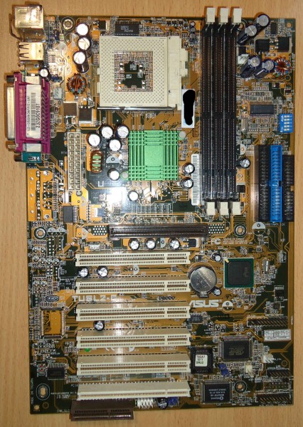
Как видите, на плате имеется всё, что нужно простым смертным и нам, оверклокерам. Самый крутой (на то время) чипсет, 3 посадочных места для SDRAM (правда максимально всего 512мб), AGP 4X(опять же со своими тараканами). Даже лампочка зелёная, отображающая наличие питания есть! Правда, плата не поддерживает процессоры первого поколения на ядре Mendocino. Сей факт немного омрачняет картину, но не на много. Давайте посмотрим на сердечко материнки:

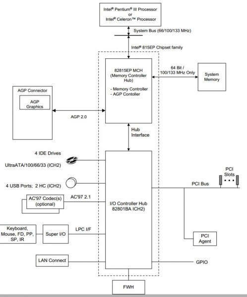
Итак, 815EP. Последователь 815Е. Разница между ними заключается лишь в том, что в 815EP нет встроенного графического контроллера (GMCH-хаба) и контроллера локальной видеопамяти (то есть материнские платы, построенные на базе чипсета 815EP, не имеют интегрированной видеоподсистемы). Вместо него используется MCH-хаб (Memory Controller Hub). В остальном же чипы 815Е и 815EP идентичны. Что к чему и через что подключается, Вы можете увидеть на схеме, представленной ниже:
Достойному чипсету, достойный помощник:

На самом деле ничего интересного и необычного. Южник как южник, нам не сильно интересны его возможности (ну почти).
Ну вот, вроде как с главным внутренним строением разобрались (ну с самым основным, что нас должно интересовать). Давайте теперь рассмотрим вблизи, с чем мы имеем дело. Ах да, покажу ещё, что производители вывели «на зад» материнки. Скудненько, но нам, оверклокерам, должно хватить

Берем плату в руки

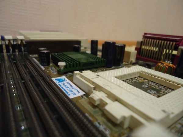
Не знаю как Вы, а я сразу смотрю на околосокетное пространство. RT9238 — данный старичок управлет почти всем важным в одиночку. Подробней как с ним бороться я расскажу во 2 части моего руководства.

Далее мой взгляд падает левее. Сразу же, по 3-м буквам ICS я понимаю, что 94201DF — заветная маркировка генератора тактовой частоты, с помощью которого (не без помощи SetFSB, естественно) мы и будем разгонять камушки. Внимание! Микросхема очень сильно греется (50-60 градусов). Это не есть хорошо. Поэтому, рекомендую установить радиаторы и организовать хоть какой-нибудь маломальский обдув. Поверьте, это пойдёт исключительно на пользу. Помимо генератора, можно заметить маленький HIP6012CB. Он отвечает за питание памяти. Подробней работу с ним, его вольтмод я рассмотрю во 2 части руководства. Внимательные люди также заметят перемычки снизу от 3-х пинового разъема для «вертолета». 3 положения джампера: 3.3 3.4 3.6 В на память (и не только, подробнее во 2 части). Например, мне хватило и 3.6В для разгона памяти до 199МГц. Также есть недокументированный метод поднятия до 3.8В, но это все очень старо и непрактично. Во 2-й статье я расскажу, как можно спокойно подать на память 4В и выше. Правда и там без сюрпризов дело не обойдётся

Так как материнка уже немолодая, крупные силовые элементы на ней очень сильно выделяются. Вот как раз на эти 2 мосфета и пал мой взор. Подробней, что это, для чего оно надо и что мы можем с этим сделать, я расскажу во 2 части, а пока лишь посоветую взгромоздить на них радиаторы, им будет очень приятно.
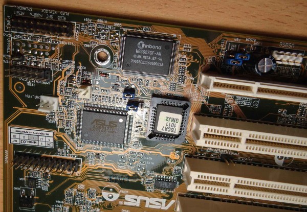
Далее я вижу микросхему BIOS, Winbond LPC I/O (именно она отвечает за клавиатуру с мышкой и ещё пару устройств ввода-вывода), включениевыключениеспикерсветодиоды — ну, вся стандартная лабудня. Помимо этого, видим ещё одну интересную «сороконожку» — чип ASUS AS99127F. Это чип мониторинга, который показывает нам температуры, снимаемые с 2-х датчиков. Они установлены: один — где-то возле процессора (непонятно где, ибо показывает страшные цифры), а второй — где-то на материнке. Помимо температур, нам еще показываются скорости всех «вертолётов», подключённых к 3-м имеющимся на плате 3-pin-ым разъемам. Как Вы понимаете, ни одна из этих «цифирей» нас не интересует, так что сильно акцентировать внимание на этом я не буду.
Ну вот вроде бы и все. Самых интересных «жителей планеты» Asus TUSL2-C мы рассмотрели и даже немного познакомились с ними. Теперь давайте запустим плату и посмотрим, что она нам может предоставить в плане разгона.
BIOS. Основные возможности.
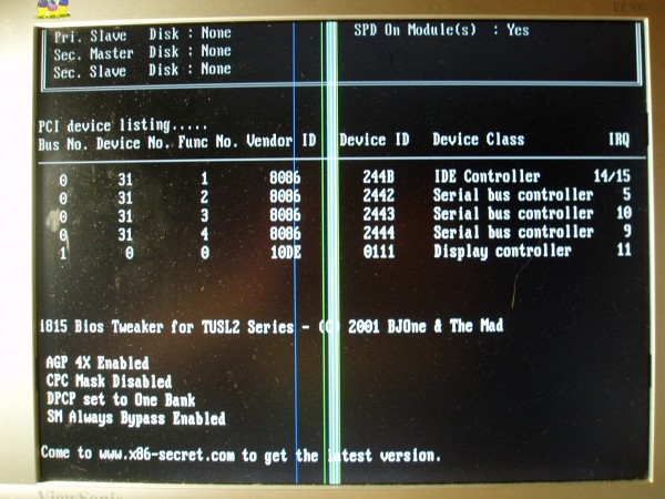
Замечание! Уважаемые, простите меня пожалуйста за не очень качественные фотографии BIOS, другого быстрого способа не нашел, а монитор вот такой, какой есть. Надеюсь на понимание
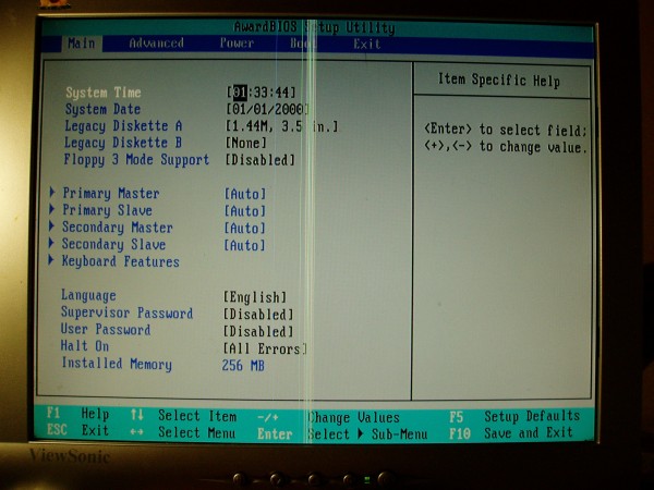
Итак, Вы собрали систему, стартанули, подождали загрузки BIOS’a и вот что самое первое Вы увидите. Оболочка Award Medalion — модификация от Асуса (прикол модификации скорее всего в бOльшем количестве функций, хотя не уверен). Главный экран. Здесь присутствуют:
- Время + дата
- Что-то, связанное с дискетками

- Какие носители информации подключены по IDE
- Язык + пароль + количество установленной RAM
- Самый важный и интересный пункт здесь для нас — это Halt ON
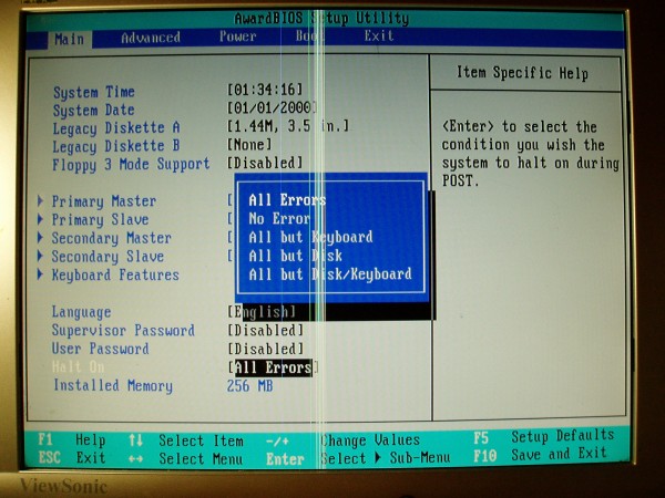
Рекомендую ставить «No Error» ибо если этого не сделать, то при каждой перезагрузке извольте жмакать F1, тем самым как бы говоря БИОСу: «Все спокойно, я оверклокер, мне не важны дата, время, вольтажи и температуры, просто загрузи мне систему, пожалуста». Идем правее.
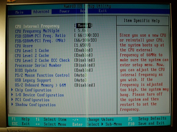
Самый важный для нас пункт меню. Пойдем по порядочку:
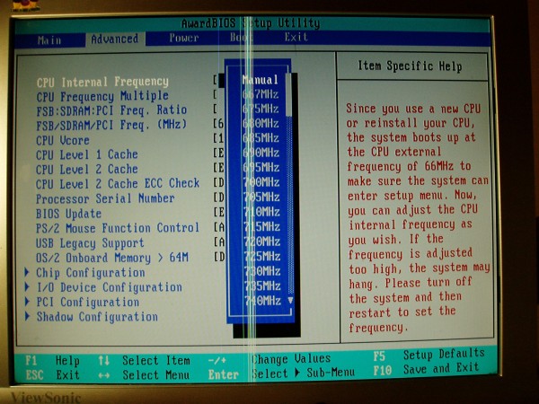
Изменение тактовой частоты процессора. Просто, по-тупому. Безо всяких множителей, вольтажей и прочего. Вот хочешь ты, вместо 666 — 700. Выставил тут, перезагрузил. Запустилось — молодец, ты оверклокер. Нет — изволь сбросить БИОС, почеши голову и посмотри на другие настройки, дабы что-то там подкрутить и попытаться приблизиться к заветной цифре. Вобщем, никогда не пользуйтесь этим меню.
Далее идет множитель. Если Вы хоть что-то знаете о процессорах Intel и их историю, то Вы, наверняка в курсе, что кроме инженерных Туалатинов и Копперов, у всех процессоров заблокированный множитель (это значит что его нельзя изменять). Поэтому мы сразу переходим еще ниже.
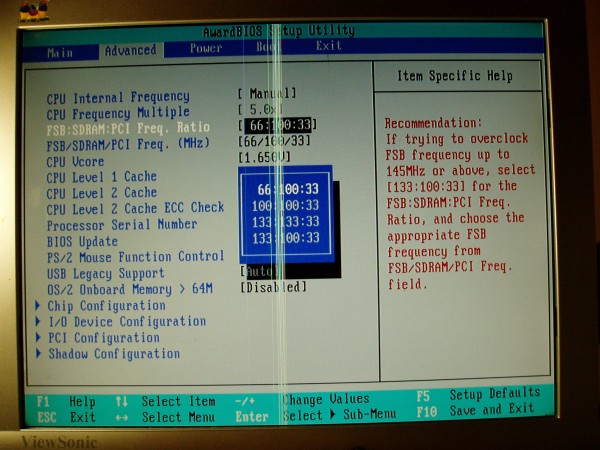
Вот это уже интересный пункт. Делители системной жиныпамятишины PCI. По порядочку — 2:3 1:1 1:1 4:3. Вот тут мы приходим к одной странной проблеме, которую я заметил в тусле. Она плохо разгоняет на множителе, отличном от 1:1. То есть, на делителе 2:3 у меня она не пошла дальше 170 по FSB, а вот при 1:1 взяла почти 200. Так что, из этого делаем вывод, что лучше пытаться разгонять на делителе 1:1 (конечно, исключая слабенькие целики на 66 шине). Клацаем стрелочку вниз.
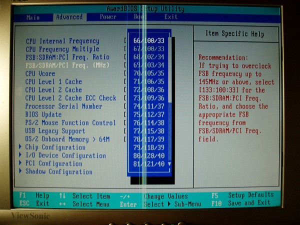
Узнаете повторение пункта, про который я гвоорил чуть выше? Опять же, он нам почти не понадобится, так что идем ниже.
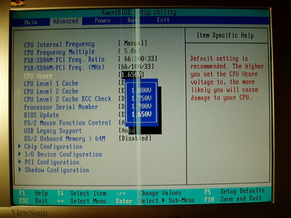
Напряжение на процессора. В зависимости от модели, степпинга, ревизии оно разное. Максимально 1.8В. Даже для туликов (это есть мало и мы с эти будем бороться во 2 части руководства). Для тестов, можно смело ставить 1.8 не боясь и отбирать «золотые» экземплярчики. Идем еще ниже.
- CPU Level 12 Cache — процессорный КЭШ 1 уровня. Про него в гугле почитайте, кому интересно. Когда прочитаете, поймете, что его отключать не надо.
- CPU Level 2 Cache ECC Check — непонятная проверка на непонятно что. Отключаем за ненадобностью.
- Processor Serial Number — туда же.
- BIOS Update — BIOS write protection — защита от записи флешек. По умолчанию — включено.
- PS/2 Mouse Function Control — Auto и пусть сам все с ними определяет (проблем с этим никогда не было)
- USB Legacy Support — Auto и смотрим пункт выше.
- OS/2 Onboard Memory > 64M — по умолчанию выключена и пусть. Если мы про нее ничего не знаем, значит это точно нам не надо и пусть будет как есть.
Заходим в Chip Configuration.
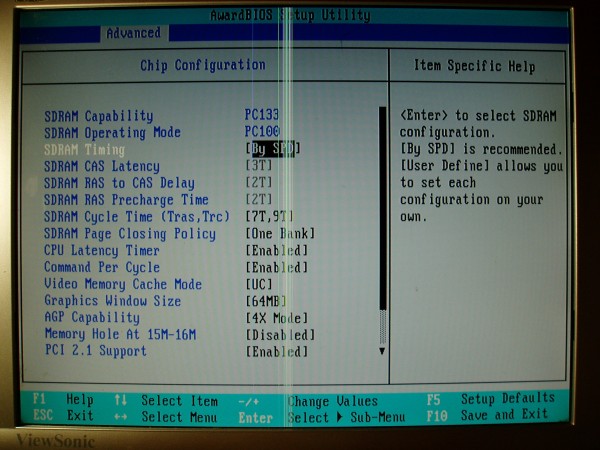
И видим пару интересных пунктов:
- Тайминги — теория хорошо описана тут. На практике рассмотрим во 2 части.
- Page closing policy — контроллер памяти закрывает открытые страницы памяти либо в одном банке (One Bank), либо во всем массиве системной памяти (All Banks). Первое параметр предпочтительнее. Почему, объясню во 2 части.
- CPU Latency Timer — oпределяет время отклика процессора при поступлении запроса по сигналу выборки адреса. Если эта опция включена (Enabled), то цикл работы процессора будет задержан только через 31 такт после поступления запроса, что положительно сказывается на общем быстродействии. При выключении данной опции (Disabled) цикл работы процессора будет прерван немедленно, что негативно сказывается на стабильности системы.
- Command Per Cycle — или Command Rate =1T Это задержка при обмене командами между контроллером памяти чипсета (процессора) и памятью (параметр tCR в диаграмме доступа). Качественные модули памяти способны работать при задержке в 1 такт (1T, 1T Command), если же стабильная работа в этом режиме не обеспечивается, устанавливается задержка в 2 такта (2T, 2T Command), что сказывается на производительности (хотя именно этот режим и предлагается по умолчанию, лекарство от этого умолчания я дам чуть ниже).
Ну а дальше ничего интересного. Кто хочет — может погуглить. Я уже это проделал, почитал и ничего интересного не нашел. Ну вот, вроде бы и все, что нас сильно интересовало. Дальше покажу фотографии остальных окон и буквально пару слов про них.
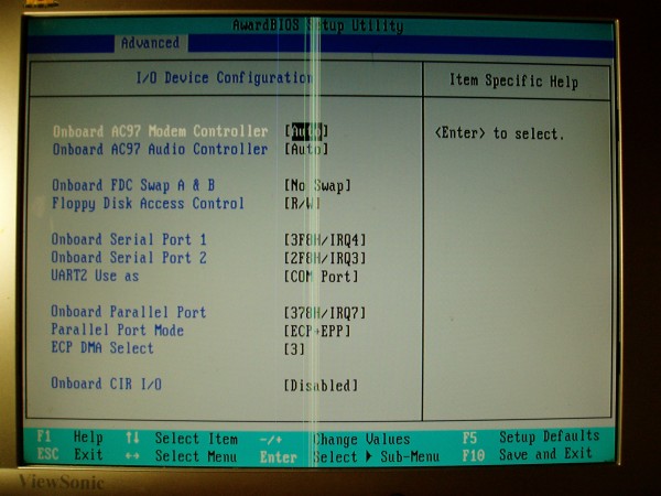
IO девайсы. Тру-оверклокеры все отключают, дабы это дало прибавок к карме. Я же ленивый, поэтому тупо забиваю. Дальше Вы поймете почему.
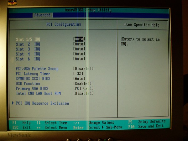
Буга-га. Неправда ли?
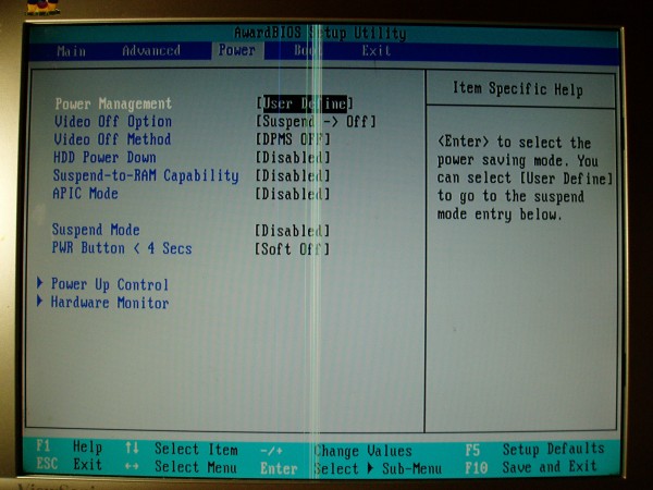
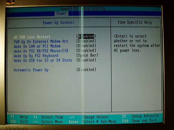
Питание. Тут мы можем даже выбрать, экономить нам на электроэнегрии и стабильности системы или нет.
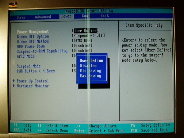
Но, скудненько как-то. Максимальное сохранениеминимальноепользовательские настройкивыключено вообще. Как-то непонятно. Поэтому оставляем в положении User Define или, если не ленивые, отключаем каждый раз. Далее советую все оставлять без изменений, так как по умолчанию, все «типо энергосберегающие» опции выключены и все настроено на нормальную, боевую работу.
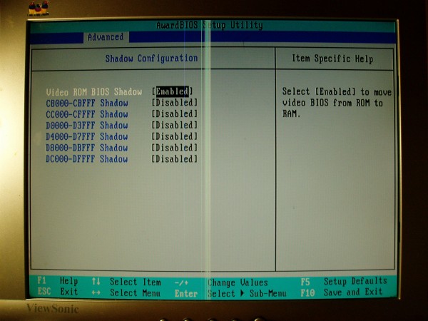
Именно про эту вкладку я Вам и говорил.
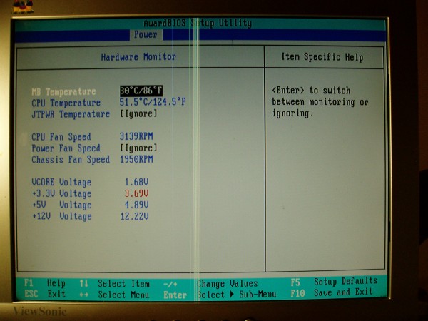
Внимательный читатель вспомнит, что я говорил про фирменный чип от Asus. Поэтому данное окошко открываем только для проверки наличия хоть какого-нибудь куллера на проца, а так же для проверки сделанного вольтмода.
Ну и последний по порядку, но не по значению пункт меню.
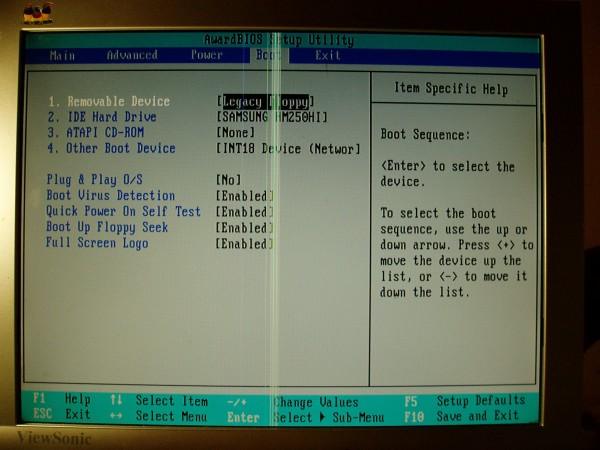
Порядок загрузки, приборы, логотипы. Обратите внимание на Boot Virus Detection. Запомните этот пункт и запомните: он всегда должен быть включен! Почему — чуть ниже. Ну а я же, со своей ленивой стороны, оставляю тут все по умолчанию, так как нам это ничего не надо и пусть будет как есть.
Вот как-то так. Согласитесь, не такой уж и емкий БИОС с одной стороны, а с другой, для нас, оверклокеров, все есть. И даже чуть больше. Поехали дальше.
i815 BIOS Tweaker
Знающие люди помнят, что плюшки, которые предоставлял родной БИОС, не такие уж и крутые. Почти все пункты со звездочкой, как это принято в наше время. Например. При разгоне процессора более чем на 5Мгц, Agp переходил в режим 2х. Для нас сейчас это вообще ничего не значит, мы не PCMark собираемся с 7950GT гонять (ну это пока не собираемся ;-)), а вот тогда, когда эта материнка была на вершине — это было просто убийственно. Так же были большие косяки с работой памяти, работой разгона в целом. Сколько было постов на форумах — сейчас уже просто не счесть. Но, просто поверьте, очень и очень много недовольных было.
И нашлись люди, умные люди, которые с помощью низкоуровневых языков программирования смогли сделать модифицированный БИОС, который исправлял косяки родной версии. И создали они специальный сайт, где выкладывали и рассказывали подробно про все свои модификации. В основном, это были изменения параметров по умолчанию, плюс исправление небольших косяков в виде падения скорости AGP.
А теперь, я отвечю, почему я заострил Ваше внимание на опции Boot Virus Detection. Именно туда защиваются специальные модицикации БИОСа. И если Вы его отключите, то ничего работать не будет (просто Ваш покорный слуга сам нарвался на эти грабли, после «недельного» схема я отошел и принялся дальше писать данное руководство). Итак, если Вы все сделали правильно, то Вы должны лицезреть на своих экранах 2 аспекта модифицированного БИОСа:
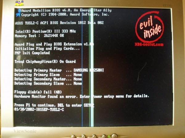
Логотип! Элементарно. Очень красивый и подходящий. Кстати, заметьте, кто-то опять забыл отключить опцию Halt On
Спасибо Вам, BJOne & The Mad за такую штуку. *Кланяется*
- AGP теперь всегда 4Х
- CPC Mask — Command Rate. Увеличение передачи скорости через память, что негативно вклияет на разгон. Поэтому она всегда отключена.
- DPCP — знакомая нам функция Page closing policy. Как видите, всегда One Bank, что положительно сказывается на разгоне.
- SM — дает дополнительные, драгоценные задержки памяти, которые так важны нам, оверклокерам
Еще одна опция, которая есть, но на скрине ее нет — TrasTtc — > 7T9T. По умолчанию было 5Т7Т. Как мы с Вами убедимся во 2 части, это тоже небольшой плюс дает.
Скажу сразу, данный модифицированный БИОС реально работает. Простой пример. Нашел я у себя в городе еще одну туслу. Там стоял простой, родной БИОС. И решил я проверить, на что способна она. Переставил все комплектующие со своей боевой туслы (199 проц и память ходили) и начал разгонять. Дальше 185 я не ушел. Делаем выводы, господа.
Подробней про БИОС, что там и как, скачать все что надо можно тут.
Заключение и предпосылки ко 2 части.
Ну вот вроде бы и все. С платой, основой как внутренней, так и внешней я Вас познакомил. Кто внимательно читал, понимает, что будет во второй части. Для тех, кто смотрел больше просто на картинки, напомню:
- вольтмоды CPU & RAM
- советы по улучшению питания
- как интересные пункты БИОСа влияют на те или иные бенчмарки
- основные фишки для получения максимальной производительности в бенчмарках (SuperPI, WPrime, PiFast, USbench 2011)
- результаты тестов Coppermine & Tualatin процессоров
- предпосылки к 3 части
Дополнительные фотографии материнки и не только тут.
Пожелания и предложения помидоры рекомендации кидать сюда.
Выражаю огромную благодарность Артему Samendk‘y за недюжее терпение и понимание, а также духовному наставнику Antinomy за постоянную мотивацию и огромную базу знаний 
СПАСИБО!
-
Contents
-
Table of Contents
-
Bookmarks
Quick Links
®
TUSL2-C
®
Intel
815EP ATX Motherboard
USER’S MANUAL
Related Manuals for Asus INTEL TUSL2-C
Summary of Contents for Asus INTEL TUSL2-C
-
Page 1
® TUSL2-C ® Intel 815EP ATX Motherboard USER’S MANUAL… -
Page 2
Product warranty or service will not be extended if: (1) the product is repaired, modified or altered, unless such repair, modification of alteration is authorized in writing by ASUS; or (2) the serial number of the product is defaced or missing. -
Page 3: Asus Contact Information
Notebook (Tel): +886-2-2890-7122 (English) Desktop/Server (Tel):+886-2-2890-7123 (English) Fax: +886-2-2893-7775 Email: tsd@asus.com.tw WWW: www.asus.com.tw FTP: ftp.asus.com.tw/pub/ASUS ASUS COMPUTER INTERNATIONAL (America) Marketing Address: 6737 Mowry Avenue, Mowry Business Center, Building 2 Newark, CA 94560, USA Fax: +1-510-608-4555 Email: tmd1@asus.com Technical Support Fax:…
-
Page 4: Table Of Contents
1. INTRODUCTION … 7 1.1 How This Manual Is Organized … 7 1.2 Item Checklist … 7 2. FEATURES … 8 2.1 The ASUS TUSL2-C … 8 2.1.1 Specifications … 8 2.1.2 Optional Components … 10 2.1.3 Performance … 10 2.1.4 Intelligence …
-
Page 5
5.3 TUSL2-C Motherboard Support CD … 80 6. SOFTWARE REFERENCE … 83 6.1 Winbond Smart Manager … 83 6.2 ASUS PC Probe … 87 6.3 Multi-Channel Audio Feature Setup … 92 6.4 ASUS LiveUpdate … 94 6.5 CyberLink PowerPlayer SE … 95 6.6 CyberLink PowerDVD … -
Page 6: Federal Communications Commission Statement
Radio Interference Regulations of the Canadian Department of Communications. This Class B digital apparatus complies with Canadian ICES-003. Cet appareil numérique de la classe B est conforme à la norme NMB-003 du Canada. ASUS TUSL2-C User’s Manual…
-
Page 7: Introduction
(1) Ribbon cable for (1) 5.25” and (2) 3.5” floppy disk drives (1) Bag of spare jumpers (1) Support drivers and utilities (1) This Motherboard User’s Manual (1) ASUS 2-port USB connector set with bracket Special Read2-In-01 SmartCard Reader Optional Item: The Power up your PC using a Smart Card.
-
Page 8: Features
2. FEATURES 2.1 The ASUS TUSL2-C The ASUS TUSL2-C motherboard is carefully designed for the demanding PC user who wants advanced features processed by the fastest processors. 2.1.1 Specifications • Latest Intel Processor Support ® P III Tualatin™ 100/133MHz FSB ®…
-
Page 9
One Touch Management: Supports an optional ASUS iPanel, an easy to access box with system information LED display, front I/O ports, and space reserved for a hard disk drive. With an ASUS iPanel, you can monitor your computer system’s vital components. -
Page 10: Optional Components
• ACPI Ready: ACPI (Advanced Configuration and Power Interface) is also imple- mented on all ASUS smart series motherboards. ACPI provides more Energy Saving Features for operating systems (OS) supporting OS Direct Power Man- agement (OSPM). With these features implemented in the OS, PCs can be ready around the clock, yet satisfy all the energy saving standards.
-
Page 11: Intelligence
Millenium, Windows NT/2000, require much more memory and hard drive space to present enormous user interfaces and run large applications. The onboard hardware ASUS ASIC in conjunction with either the bundled ASUS PC Probe or Intel LDCM will warn the user before the system resources are used up to prevent possible application crashes.
-
Page 12: Tusl2-C Motherboard Components
1 Microphone Connector (on audio model only) Network Features Wake-On-LAN Connector … 20 Wake-On-Ring Connector … 10 Hardware Monitoring System Voltage Monitoring (integrated in ASUS ASIC) … 14 3 Fan Power and Speed Monitoring Connectors Power ATX Power Supply Connector … 1 Special Feature Onboard LED …
-
Page 13
2. FEATURES 2.2.1 Component Locations ASUS TUSL2-C User’s Manual… -
Page 14: Hardware Setup
Line Accelerated Graphics Port (AGP) AAPANEL WOL_CON MODEM C-Media Audio PLED2 AUDIO_EN CNR_SLOT Grayed components are optional at the time of purchase. ASUS TUSL2-C User’s Manual Intel 815EP Chipset PCI1 CR2032 3V Lithium Cell CMOS Power PCI2 ® PCI3 PCI4…
-
Page 15: Layout Contents
Internal Microphone Connector (3 pin) 15) AFPANEL / IR_CON p.36 ASUS iPanel Connector (12-1 pin) 16) SMARTCON p.36 ASUS SmartCard Connector (10-1 pin ) 17) AAPANEL p.37 ASUS iPanel Audio Connector (12-1 pin) 18) ACHA p.37 Chassis Intrusion Connector (2 pin)
-
Page 16
27) SPEAKER (PANEL) 28) MSG.LED (PANEL) 29) SMI (PANEL) 30) PWRSW (PANEL) 31) RESET (PANEL) ASUS TUSL2-C User’s Manual p.38 Wake-On-LAN Connector (3 pin) p.38 Wake-On-Ring Connector (2 pin) p.39 USB Headers (10-1 pin) p.39 SMBus Connector (5-1 pin) p.40 ATX Power Supply Connector (20 pin) p.40 Power Supply Thermal Sensor Connector (2 pin) -
Page 17: Hardware Setup Procedure
The onboard LED when lit acts as a reminder that the system is in suspend or soft-off mode and not pow- ered OFF. ® TUSL2-C TUSL2-C Onboard LED ASUS TUSL2-C User’s Manual PLED2 Standby Powered Power…
-
Page 18
NOTE: In JumperFree™ mode, all dip switches must be set to OFF. Setting Disable (Jumper) Enable (JumperFree) [2-3] (default) ® TUSL2-C TUSL2-C JumperFree™ Mode Setting ASUS TUSL2-C User’s Manual 1. Frequency Selection 2. Frequency Selection 3. Frequency Selection 4. Frequency Selection 5. Frequency Selection. [1-2] Disable… -
Page 19
2. The total current consumed must NOT exceed the power supply capability (+5VSB) whether under normal working conditions or in the sleep mode. Setting USWR01, USWR56 Disable [1-2] (default) Enable [2-3] ® TUSL2-C TUSL2-C USB Device Wake Up ASUS TUSL2-C User’s Manual USBPWR01 Disable Enable (Default) USBPWR56 Disable Enable (Default) -
Page 20
NOTE: This jumper must be set in conjunction with Wake On PS2 KB/PS2 Mouse/CIR in 4.5.1 Power Up Control. Setting Enable Disable ® TUSL2-C TUSL2-C Keyboard Power Setting ASUS TUSL2-C User’s Manual AUDIO_EN [1-2] (default) [2-3] AUDIO_EN Enable Disable (Default) -
Page 21
Using a higher voltage may help when overclocking but may result in the shortening of your computer component’s life. It is highly recommended that you leave this setting on its default. ASUS TUSL2-C User’s Manual 3.30 V 3.40 V 3.60 V… -
Page 22
NOTE: If the processor does not have a locked Frequency Multiple, you must use CPU Core:Bus Freq. Multiple in 4.4 Advanced Menu to set the Frequency Multiple. If the Frequency Multiple is locked, setting the Frequency Multiple in BIOS setup will have no effect. ASUS TUSL2-C User’s Manual 66MHz 100MHz 103MHz… -
Page 23
108.8 133:100 150.0 112.5 133:100 160.0 120.0 For updated processor settings, visit ASUS’s web site (see ASUS CONTACT IN- FORMATION) ASUS TUSL2-C User’s Manual Frequency Selection Switches [O N ] [O N ] [O N ] [O N ] [O N ] [O N ]… -
Page 24: System Memory (Dimm)
NOTE: Make sure the total installed memory does not exceeds 512MB. Otherwise, the system may hang during startup. 3.5.1 General DIMM Notes • ASUS motherboards support SPD (Serial Presence Detect) DIMMs. This is the memory of choice for best performance vs. stability. • BIOS shows SDRAM memory on bootup screen.
-
Page 25: Memory Installation
DIMM slot on the motherboard. You must tell your retailer the correct DIMM type before purchasing. This motherboard supports four clock signals per DIMM. ASUS TUSL2-C User’s Manual 20 Pins 60 Pins…
-
Page 26: Central Processing Unit (Cpu)
CAUTION! Be careful not to scrape the motherboard when mounting a clamp- style processor fan or else damage may occur to the motherboard. ® TUSL2-C TUSL2-C Socket 370 ASUS TUSL2-C User’s Manual Pentium III Gold Arrow Tualatin/ Celeron Gold Arrow…
-
Page 27: Expansion Cards
MIDI enabled, another IRQ will be used, leaving 4 IRQs free. Standard Interrupt Assignments Priority *These IRQs are usually available for ISA or PCI devices. ASUS TUSL2-C User’s Manual Standard Function System Timer Keyboard Controller Programmable Interrupt…
-
Page 28: Communication And Networking Riser (Cnr) Slot
This provides upgradeable network, audio, and/or modem solutions at an incredibly low cost. NOTE: CNRs are not included with this motherboard. ® TUSL2-C TUSL2-C Communication & Networking Riser Connector ASUS TUSL2-C User’s Manual — — — — — —…
-
Page 29: Accelerated Graphics Port (Agp) Slot
3. HARDWARE SETUP 3.7.4 Accelerated Graphics Port (AGP) Slot This motherboard provides an accelerated graphics port (AGP 4X) slot to support AGP graphics cards. ® TUSL2-C TUSL2-C Accelerated Graphics Port (AGP) ASUS TUSL2-C User’s Manual…
-
Page 30: External Connectors
This connection is for a standard keyboard using an PS/2 plug (mini DIN). This connector will not allow standard AT size (large DIN) keyboard plugs. You may use a DIN to mini DIN adapter on standard AT keyboards. PS/2 Keyboard (6-pin Female) ASUS TUSL2 User’s Manual…
-
Page 31
5) Serial Port Connectors (Teal/Turquoise 9-pin COM1, 10-1 pin COM2) Two serial ports are ready for a mouse or other serial devices. See Onboard Serial Port 1/2 in 4.4.2 I/O Device Configuration for settings. COM1 Serial Ports (9-pin Male) ASUS TUSL2 User’s Manual COM2… -
Page 32
(Pin 5 is removed to prevent inserting in the wrong orienta- tion when using ribbon cables with pin 5 plugged). ® TUSL2-C TUSL2-C Floppy Disk Drive Connector ASUS TUSL2 User’s Manual Game/MIDI (15-pin Female) Line Out Line In 1/8″ Stereo Audio Connectors… -
Page 33
UltraDMA/100 IDE devices must use a 40-pin 80-conductor IDE cable for 100MByte/sec transfer rates. ® TUSL2-C TUSL2-C IDE Connectors ASUS TUSL2 User’s Manual NOTE: Orient the red markings (usually zigzag) on the IDE ribbon cable to PIN 1. PIN 1… -
Page 34
NOTE: The “Rotation” signal is to be used only by a specially designed fan with rotation signal. The Rotations per Minute (RPM) can be read directly from the ASUS iPanel or monitored using a utility such as ASUS PC Probe or Intel LDCM. WARNING! The CPU and/or motherboard will overheat if there is no airflow across the CPU and onboard heatsinks. -
Page 35
This connector allows you to attach a chassis mounted microphone to the mother- board instead of having to attach an external microphone onto the ATX connectors. ® TUSL2-C TUSL2-C Internal Microphone Connector ASUS TUSL2 User’s Manual Right Audio Channel AUX (White) Ground Left Audio Channel CD (Black) -
Page 36
I/O ports, status LEDs, and space reserved for a hard disk drive. If you are not using an ASUS iPanel, you can connect an optional wireless transmitting and receiving infrared module to the SIR connector or an optional… -
Page 37
3. HARDWARE SETUP 17) ASUS iPanel Audio Connector (12-1 pins AAPANEL) Connect the audio cable from the optional ASUS iPanel to this for front panel audio control. ® TUSL2-C TUSL2-C Audio Panel Connectors 18) Chassis Intrusion Lead (2-pin ACHA) This lead is for a chassis designed for chassis intrusion detection. After-market toggle switches may also be installed to the chassis panel or on any removable components. -
Page 38
19) Wake-On-LAN Connector (3-pin WOL_CON) This connector supplies a LAN card with a Wake-On-LAN output, such as the ASUS PCI-L101 Ethernet card (see 7. Appendix). The connector powers up the system when a wakeup packet or signal is received through the LAN card. -
Page 39
® TUSL2-C TUSL2-C SMBus Connector ASUS TUSL2 User’s Manual USB56 Ground SMBDATA SMBCLK… -
Page 40
24) Power Supply Thermal Sensor Connector (2-pin JTPWR) If you have a power supply with thermal monitoring, connect its thermal sensor cable to this connector. ® TUSL2-C TUSL2-C Thermal Sensor Connector ASUS TUSL2 User’s Manual +12.0 Volts +5.0 Volts +5V Standby +5.0 Volts Power Good -5.0 Volts… -
Page 41
This 2-pin connector supplies the case-mounted reset switch for rebooting your computer without having to turn off your power switch. This is a preferred method of rebooting to prolong the life of the system’s power supply. ASUS TUSL2 User’s Manual Keyboard Lock Speaker… -
Page 42
3. HARDWARE SETUP (This page was intentionally left blank.) ASUS TUSL2 User’s Manual… -
Page 43: Starting Up The First Time
Long beeps in an endless loop One long beep followed by three short beeps High frequency beeps when system is working ASUS TUSL2-C User’s Manual Meaning No error during POST No DRAM installed or detected Video card not found or video card…
-
Page 44
Shut Down, and then click Shut down the computer? The power supply should turn off after Windows shuts down. NOTE: The message “You can now safely turn off your computer” will not appear when shutting down with ATX power supplies. ASUS TUSL2-C User’s Manual… -
Page 45: Bios Setup
4. In DOS mode, type A:AFLASH <Enter> to run AFLASH. IMPORTANT! If the word “unknown” appears after Flash Memory:, the memory chip is either not programmable or is not supported by the ACPI BIOS and therefore, cannot be programmed by the Flash Memory Writer utility. ASUS TUSL2-C User’s Manual…
-
Page 46: Bios Setup
5. Select 1. Save Current BIOS to File from the Main menu and press <Enter>. The Save Current BIOS To File screen appears. 6. Type a filename and the path, for example, A:XXX-XX.XXX and then press <Enter>. ASUS TUSL2-C User’s Manual…
-
Page 47: Updating Bios Procedures
BIOS revision will solve your problems. Careless updating can result in your motherboard having more problems! 1. Download an updated ASUS BIOS file from the Internet (WWW or FTP) (see ASUS CONTACT INFORMATION on page 3 for details) and save to the boot floppy disk you created earlier.
-
Page 48
BIOS file you saved to the boot disk. If the Flash Memory Writer utility is not able to successfully update a complete BIOS file, the system may not boot. If this happens, call the ASUS service center for support. ASUS TUSL2-C User’s Manual… -
Page 49: Bios Setup Program
POST. NOTE: Because the BIOS software is constantly being updated, the following BIOS screens and descriptions are for reference purposes only and may not re- flect your BIOS screens exactly. ASUS TUSL2-C User’s Manual…
-
Page 50: Bios Menu Bar
Brings up a selection menu for the highlighted field <Home> or <PgUp> Moves the cursor to the first field <End> or <PgDn> Moves the cursor to the last field <F5> Resets the current screen to its Setup Defaults <F10> Saves changes and exits Setup ASUS TUSL2-C User’s Manual…
-
Page 51: General Help
Setup program, note that explanations appear in the Item Specific Help window located to the right of each menu. This window displays the help text for the cur- rently highlighted field. NOTE: The item heading in square brackets represents the default setting for that field. ASUS TUSL2-C User’s Manual…
-
Page 52: Main Menu
This is required to support older Japanese floppy drives. Floppy 3 Mode support will allow reading and writing of 1.2MB (as opposed to 1.44MB) on a 3.5-inch diskette. Configuration options: [Disabled] [Drive A] [Drive B] [Both] ASUS TUSL2-C User’s Manual…
-
Page 53: Primary & Secondary Master/Slave
Primary IDE hard disk drives must have its partition set to active (also possible with FDISK). Other options for the Type field are: [None] — to disable IDE devices ASUS TUSL2-C User’s Manual…
-
Page 54
NOTE: To make changes to this field, the Type field must be set to [User Type HDD] and the Translation Method field must be set to [Manual]. ASUS TUSL2-C User’s Manual… -
Page 55
IDE devices. Set to [Disabled] to suppress Ultra DMA ca- pability. NOTE: To make changes to this field, the Type field must be set to [User Type HDD]. Configuration options: [0] [1] [2] [3] [4] [Disabled] ASUS TUSL2-C User’s Manual… -
Page 56: Keyboard Features
[6/Sec] [8/Sec] [10/Sec] [12/Sec] [15/Sec] [20/Sec] [24/Sec] [30/Sec] Keyboard Auto-Repeat Delay [1/4 Sec] This field sets the time interval for displaying the first and second charac- ters. Configuration options: [1/4 Sec] [1/2 Sec] [3/4 Sec] [1 Sec] ASUS TUSL2-C User’s Manual…
-
Page 57
Disk] [All but Disk/Keyboard] Installed Memory [XXX MB] This display-only field displays the amount of conventional memory detected by the system during bootup. You do not need to make changes to this field. ASUS TUSL2-C User’s Manual Short solder points to Clear CMOS… -
Page 58: Asus Tusl2-C User’s Manual
According to the previous setup field FSB:SDRAM:PCI Freq. Ratio, this field offers 32 sets of Front Side Bus, SDRAM, and PCI bus frequencies for you to choose. Available options when FSB:SDRAM:PCI Freq. Ratio is set to [133:133:33] ASUS TUSL2-C User’s Manual…
-
Page 59
[Auto] OS/2 Onboard Memory > 64M [Disabled] When using OS/2 operating systems with installed DRAM of greater than 64MB, you need to set this option to [Enabled]; otherwise, leave this on [Disabled]. Configuration options: [Disabled] [Enabled] ASUS TUSL2-C User’s Manual… -
Page 60
If your system crashes or hangs due to improper frequency settings, power OFF your system and restart. The system will start up in safe mode running at a bus speed of 66MHz and enter BIOS setup. ASUS TUSL2-C User’s Manual… -
Page 61: Chip Configuration
NOTE: The following 3 fields will only be adjustable when SDRAM Con- figuration is set to [User Define]. SDRAM CAS Latency This controls the latency between the SDRAM read command and the time that the data actually becomes available. ASUS TUSL2-C User’s Manual…
-
Page 62
[4X Mode] even when you are using an AGP 2x video card. When set to [2X Mode], the AGP interface will only provide a peak data throughput of 533MB/s even if you are using an AGP 4x card. Configuration options: [2X Mode] [4X Mode] ASUS TUSL2-C User’s Manual… -
Page 63
Onboard PCI IDE Enable [Both] You can select to enable the primary IDE channel, secondary IDE channel, both, or disable both channels. Configuration options: [Both] [Disabled] SDRAM Data Driving Mode [Normal] Leave on default setting. Configuration options: [Normal] [Strong] ASUS TUSL2-C User’s Manual… -
Page 64: I/O Device Configuration
Onboard Serial Port 2 [2F8H/IRQ3] These fields allow you to set the addresses for the onboard serial connec- tors. Serial Port 1 and Serial Port 2 must have different addresses. Con- figuration options: [3F8H/IRQ4] [2F8H/IRQ3] [3E8H/IRQ4] [2E8H/ IRQ10] [Disabled] ASUS TUSL2-C User’s Manual…
-
Page 65
ECP mode. This selection is available only if you select [ECP] or [ECP+EPP] in Parallel Port Mode above. Configuration options: [1] [3] Onboard CIR I/O [Disabled] This field sets the address of the onboard Consumer IR connector. Con- figuration options: [Disabled] [2E0-2E8H] [3E0-3E8H] ASUS TUSL2-C User’s Manual… -
Page 66: Pci Configuration
BIOS, the Symbios SCSI card will not function. Con- figuration options: [Auto] [Disabled] USB Function [Enabled] This motherboard supports Universal Serial Bus (USB) devices. Set to [En- abled] if you want to use USB devices. Configuration options: [Disabled] [Enabled] ASUS TUSL2-C User’s Manual…
-
Page 67
IRQ XX Reserved [No] These fields indicate whether or not the displayed IRQ for each field is being used by a specified device. The default value indicates that the dis- played IRQ is not used. Configuration options: [No] [Yes] ASUS TUSL2-C User’s Manual… -
Page 68: Shadow Configuration
ROMs on them, you will need to know which addresses the ROMs use to shadow them specifically. Shadowing a ROM reduces the memory available between 640K and 1024K by the amount used for this purpose. Configuration options: [Disabled] [Enabled] ASUS TUSL2-C User’s Manual…
-
Page 69: Power Menu
Windows 3.x and Windows 95, you need to install Windows with the APM feature. For Windows 98 and later, APM is automatically installed. A battery and power cord icon labeled “Power Management” will appear in the “Control Panel.” Choose “Advanced” in the Power Management Properties dialog box. ASUS TUSL2-C User’s Manual…
-
Page 70
4 seconds will place the system in sleep mode. Regardless of the setting, holding the ATX switch for more than 4 seconds will power off the system. Configuration options: [Soft off] [Suspend] ASUS TUSL2-C User’s Manual… -
Page 71: Power Up Control
Con- figuration options: [Disabled] [Enabled] IMPORTANT: This feature requires an optional network interface card with Wake- On-LAN and an ATX power supply with at least 720mA +5V standby power. ASUS TUSL2-C User’s Manual…
-
Page 72
[By Date]. NOTE: Auto- matic Power Up will not work if the system is powered down by operating systems, such as Windows 98, which have ACPI support enabled. Con- figuration options: [Disabled] [Everyday] [By Date] ASUS TUSL2-C User’s Manual… -
Page 73: Hardware Monitor
NOTE: If any of the monitored items is out of range, an error message will appear: “Hardware Monitor found an error. Enter Power setup menu for details”. You will then be prompted to “Press F1 to continue, DEL to enter SETUP”. ASUS TUSL2-C User’s Manual…
-
Page 74: Boot Menu
Pressing [Enter] will show the product IDs of all your con- nected ATAPI CD-ROM drives. Other Boot Device Select [INT18 Device (Network)] Configuration options: [Disabled] [SCSI Boot Device] [INT18 Device (Net- work)] [LANDesk (R) Service Agent] ASUS TUSL2-C User’s Manual…
-
Page 75
When enabled, the BIOS will seek the floppy disk drive to determine whether the drive has 40 or 80 tracks. Configuration options: [Disabled] [Enabled] Full Screen Logo [Enabled] When enabled, the personalized boot logo is functional. Configuration options: [Enabled] [Disabled] ASUS TUSL2-C User’s Manual… -
Page 76: Exit Menu
This option should only be used if you do not want to save the changes you have made to the Setup program. If you have made changes to fields other than system date, system time, and password, the system will ask for con- firmation before exiting. ASUS TUSL2-C User’s Manual…
-
Page 77: Load Setup Defaults
This option saves your selections without exiting the Setup program. You can then return to other menus and make changes. After selecting this op- tion, all selections are saved and a confirmation is requested. Select [Yes] to save any changes to the non-volatile RAM. ASUS TUSL2-C User’s Manual…
-
Page 78
4. BIOS SETUP (This page was intentionally left blank.) ASUS TUSL2-C User’s Manual… -
Page 79: Software Setup
NOTE: Because there are various motherboard settings, options, and expansion cards, the following can only be used as a general reference and may not be an exact reflection of your system. ASUS TUSL2-C User’s Manual…
-
Page 80: Tusl2-C Motherboard Support Cd
Intel LDCM Client Setup: Installs software to monitor the Client system. The LANDesk Client Manager must be installed to use the hardware manager features. • ASUS BIOS Flash Utility for LDCM: Installs a utility that can remotely flash a client PC’s BIOS when used in conjunction with Intel LDCM Administrator. •…
-
Page 81
Cyberlink Video and Audio Applications: Installs Cyberlink PowerPlayer SE, PowerDVD Trial, and Cyberlink VideoLive Mail. • ASUS Screen Saver: Installs ASUS screen saver on the PC. • Show Motherboard Information: Allows you to view information about your motherboard, such as product name, BIOS version, and CPU. -
Page 82
5. SOFTWARE SETUP (This page was intentionally left blank.) ASUS TUSL2-C User’s Manual… -
Page 83: Software Reference
Advanced BIOS menu select the I/O Device Configuration sub-menu, go to UART2 and select Smart Card Read, save and exit. Finish booting up. Insert the ASUS Support CD and click on the selection: Winbond Smart Manager Application.
-
Page 84
Smart card system software base components support various types of smart card applications; all system components are compatible with Windows 98, ME and 2000. However, the Windbond Smart Manager application is readily compatible only with Windows 98 and ME. ASUS TUSL2-C User’s Manual… -
Page 85
Click OK. The card reader detects the smart card ID. Smart Manager registers the smart card for security capability and prompts to click OK. The card’s security status is displayed in the main program window. ASUS TUSL2-C User’s Manual… -
Page 86
PC or decode encrypted files. Test each new smart card to ensure that it is completely compatible with the card reader; the Read2- In-01 Smart Card Reader is designed only to read cards with the standard PC/SC mini-chip configuration. ASUS TUSL2-C User’s Manual… -
Page 87: Asus Pc Probe
ASUS Utility, and then click Probe Vx.xx. The PC Probe icon will appear on the taskbar’s system tray indicating that ASUS PC Probe is running. Clicking the icon will allow you to see the status of your PC. ASUS TUSL2-C User’s Manual…
-
Page 88: Using Asus Pc Probe
6. SOFTWARE REFERENCE 6.2.2 Using ASUS PC Probe Monitoring Monitor Summary Shows a summary of the items being monitored. Temperature Monitor Shows the PC’s temperature. Temperature Warning threshold adjustment (Move the slider up to increase the threshold level or down to decrease…
-
Page 89
Lets you record the current monitoring activity of a certain component of your PC for future reference. Information Hard Drives Shows the used and free space of the PC’s hard disk drives and the file allocation table or file system used. ASUS TUSL2-C User’s Manual… -
Page 90
Shows information pertinent to the PC, such as CPU type, CPU speed, and in- ternal/external frequencies, and memory size. Utility Lets you run programs outside of the ASUS Probe modules. To run a program, click Execute Program. ASUS TUSL2-C User’s Manual… -
Page 91: Asus Pc Probe Task Bar Icon
6. SOFTWARE REFERENCE 6.2.3 ASUS PC Probe Task Bar Icon Right-clicking the PC Probe icon will bring up a menu to open or exit ASUS PC Probe and pause or resume all system monitoring. When the ASUS PC Probe senses…
-
Page 92: Multi-Channel Audio Feature Setup
1. The Audio Demo program offers an easy way to test and tune your new speaker system. Activate the Multi-Channel Audio Demo program from the PCI Audio Applications group on the Main Program menu using the Windows Start button: ASUS TUSL2-C User’s Manual…
-
Page 93
Light Blue Line In Pink Mic In Note: See 7 in Section 3, Motherboard settings for the Bass/Center Jumper settings to fine tune the output signals. ASUS TUSL2-C User’s Manual Line Out 4-Speaker 6-Speaker Line Out/ Line Out/ Front Spkr Out… -
Page 94: Asus Liveupdate
6. SOFTWARE REFERENCE 6.4 ASUS LiveUpdate ASUS LiveUpdate is a utility that allows you to update your motherboard’s BIOS and drivers. The use of this utility requires that you are properly con- nected to the Internet through an Internet Service Provider (ISP).
-
Page 95: Cyberlink Powerplayer Se
Stop Backward Scan Backstep Frame Previous Stop Configuration i-Power! CD Mode Shuffle Karaoke Next angle Capture frame ASUS TUSL2-C User’s Manual Eject Help Power Off Forward Scan Step Frame Next Play Increase Volume Mute Decrease Volume Next audio stream Next subtitle…
-
Page 96: Cyberlink Powerdvd
6.6.1 Starting CyberLink PowerDVD To start CyberLink PowerDVD, click the Windows Start button, point to Programs, and then CyberLink PowerDVD, and then click PowerDVD. 6.6.2 CyberLink PowerDVD User Interface Main Display ASUS TUSL2-C User’s Manual Control Full Screen / CD/File Control…
-
Page 97: Cyberlink Videolive Mail
VLM 3 supports all the hardware devices that are compliant with Video for Win- dows standard. Video for Windows is a well-accepted and well-tested standard. Thus, users do not have to worry about compatibility issues. ASUS TUSL2-C User’s Manual…
-
Page 98: Cyberlink Videolive Mail User Interface
Next when ready. 7. Configuration done. Click Finish to complete the environmental setting proce- dure. 6.7.2 CyberLink VideoLive Mail User Interface Snapshot to File Video Configuration ASUS TUSL2-C User’s Manual Start Playback Stop Recording / Playback Start Recording Pause Exit…
-
Page 99: Appendix
BIOS file into the EEPROM. Bit (Binary Digit) Represents the smallest unit of data used by the computer. A bit can have one of two values: 0 or 1. ASUS TUSL2-C User’s Manual Bandwidth Data Transfer Rate 33MHz…
-
Page 100
IDE devices integrate the drive control circuitry directly on the drive itself, elimi- nating the need for a separate adapter card (in the case for SCSI devices). UltraDMA/ 33 IDE devices can achieve up to 33MB/Sec transfer. ASUS TUSL2-C User’s Manual… -
Page 101
Developed by Rambus, Inc., this type of memory can deliver up to 1.6GB of data per second. RDRAM is the first interface standard that can be directly implemented on high performance VLSI components such as, CMOS DRAMs, memory control- lers, and graphics/video ICs. ASUS TUSL2-C User’s Manual… -
Page 102
USB 2.0 provides twice the transfer rate compared to USB 1.0 and competes with the 1394 standard. Wake-On-LAN Computer will automatically wake-up upon receiving a wake-up packet through a Network interface when it is under power soft-off, suspend or sleep mode. ASUS TUSL2-C User’s Manual… -
Page 103: Index
Using 96 CyberLink PowerPlayer SE Using 95 CyberLink VideoLive Mail Using 97 Cylinders 54 Discard Changes 77 ASUS TUSL2-C User’s Manual INDEX ECP DMA Select 65 Exit Discarding Changes 76 Exit Saving Changes 76 Expansion Cards AGP Pro 29 Assigning IRQs 27…
-
Page 104
Using 96 PowerPlayer SE Using 95 Procedure CPU Installation 26 Procedures ASUS TUSL2-C User’s Manual INDEX Updating BIOS 46 PWR Button < 4 Secs 70 PWR Up On Modem Act 71 Quick Power On Self Test 75 Removable Device 74… -
Page 105
-12 73 -5 73 VCORE 73 Wake On LAN 71 Wake On PS2 KB/PS2 Mouse/CIR 72 Wake On USB for STR State 72 Wake Up By Keyboard 72 Windbond Smart Manager 83 Modes 86 Using 85 ASUS TUSL2-C User’s Manual INDEX… -
Page 106
NOTES ASUS TUSL2-C User’s Manual…
-
Asus TUSL2-C — page 1
® TUSL2-C Intel ® 815EP A TX Motherboard USER ’ S MANUAL …
-
Asus TUSL2-C — page 2
2 ASUS TUSL2-C User’ s Manual USER’S NOTICE Product Name: ASUS TUSL2-C Manual Revision: 1.04 E769 Release Date: May 2001 No part of this manual, including the products and software described in it, may be repro- duced, transmitted, transcribed, stored in a retrieval system, or translated into any language in any form or by any means, except …
-
Asus TUSL2-C — page 3
ASUS TUSL2-C User’ s Manual 3 ASUS CONT ACT INFORMA TION ASUST eK COMPUTER INC. (Asia-Pacific) Marketing Address: 150 Li-T e Road, Peitou, T aipei, T aiwan 1 12 T elephone: +886-2-2894-3447 Fax: +886-2-2894-3449 Email: info@asus.com.tw T echnical Support MB/Others (T el): +886-2-2890-7121 (English) Notebook (T el): +886-2-2890-7122 (English) Desk …
-
Asus TUSL2-C — page 4
4 ASUS TUSL2-C User’ s Manual CONTENTS 1. INTRODUCTION ………………………………………………………………….. 7 1.1 How This Manual Is Or ganized ………………………………………….. 7 1.2 Item Checklist ………………………………………………………………….. 7 2. FEA TURES ………….. …
-
Asus TUSL2-C — page 5
ASUS TUSL2-C User’ s Manual 5 CONTENTS 4.4 Advanced Menu ……………………………………………………………… 58 4.4.1 Chip Configuration ……………………………………………….. 61 4.4.2 I/O Device Configuration ………………………………………. 64 4.4.3 PCI Configuration ……………………. …
-
Asus TUSL2-C — page 6
6 ASUS TUSL2-C User’ s Manual FCC & DOC COMPLIANCE Federal Communications Commission Statement This device complies with FCC Rules Part 15. Operation is subject to the following two conditions: • This device may not cause harmful interference, and • This device must accept any interference received, including interference that may cause u …
-
Asus TUSL2-C — page 7
ASUS TUSL2-C User ’ s Manual 7 1.1 How This Manual Is Organized This manual is divided into the following sections: 1. INTRODUCTION Manual information and checklist 2. FEA TURES Production information and specifications 3. HARDW ARE SETUP Instructions on setting up the motherboard. 4. BIOS SETUP Instructions on setting up the BIOS 5. SOFTW ARE SE …
-
Asus TUSL2-C — page 8
8 ASUS TUSL2-C User ’ s Manual 2.1 The ASUS TUSL2-C The ASUS TUSL2-C motherboard is carefully designed for the demanding PC user who wants advanced features processed by the fastest processors. 2.1.1 Specifications • Latest Intel Processor Support P III ® T ualatin ™ 100/133MHz FSB FC-PGA2 P III ® Coppermine ™ 100/133MHz FSB FC-PGA Celero …
-
Asus TUSL2-C — page 9
ASUS TUSL2-C User ’ s Manual 9 2. FEA TURES 2. FEA TURES Specifications • Around-the-Clock Intrusion Detection: Chassis intrusion circuitry can log chassis open events into LDCM. The onboard battery supports detection even when normal power is removed and through a new design, battery drain is even lower than the R TC used for keeping time! • …
-
Asus TUSL2-C — page 10
10 ASUS TUSL2-C User ’ s Manual 2. FEA TURES Performance 2. FEA TURES 2.1.2 Optional Components The following onboard components are optional at the time of purchase: • Onboard Audio: C-Media Audio Chip CMI8738 supporting the latest PCI 6 channel and HR TF 3D Audio sound circuitry . A software package helps setup the multi-channel PC sound syst …
-
Asus TUSL2-C — page 11
ASUS TUSL2-C User ’ s Manual 11 2. FEA TURES 2. FEA TURES Intelligence 2.1.4 Intelligence • Fan Status Monitoring and Alarm: T o prevent system overheat and system damage, the CPU, power supply , and system fans can be monitored for RPM and failure. All the fans are set for its normal RPM range and alarm thresholds. • T emperature Monitoring …
-
Asus TUSL2-C — page 12
12 ASUS TUSL2-C User ’ s Manual .. (Bottom) 22 Location Processor Support Socket 370 for Pentium III/Celeron (FC-PGA/2) Processors .. 2 Feature Setting DIP Switches …………………………………………… 6 Chipsets Intel 815EP Chipset ………………………………………………………… 3 Intel I/O Controlle …
-
Asus TUSL2-C — page 13
ASUS TUSL2-C User ’ s Manual 13 2. FEA TURES 2. FEA TURES Component Location 2.2.1 Component Locations 23 4 5 13 8 14 21 11 23 24 25 26 27 7 6 12 18 17 10 16 9 22 1 15 20 19 …
-
Asus TUSL2-C — page 14
14 ASUS TUSL2-C User ’ s Manual 3. HARDW ARE SETUP 3.1 TUSL2-C Motherboard Layout PS/2KBMS T : Mouse B: Ke yboard PWR_F AN GAME_AUDIO Mic In Line Out Line In PCI1 PCI2 PCI4 PCI3 P ANEL IDELED FLOPPY SECONDARY IDE PRIMARY IDE TUSL2-C CHA_F AN CD AUX ® PLED2 Accelerated Graphics Port (AGP) CR2032 3V Lithium Cell CMOS Power DIMM1 (64/72 bit, 168-pi …
-
Asus TUSL2-C — page 15
ASUS TUSL2-C User ’ s Manual 15 3. HARDW ARE SETUP 3.2 Layout Contents Motherboard Settings 1) JEN p.18 JumperFree ™ Mode (Enable/Disable) 2) USWR01 p.19 USB Device W ake Up (Enable/Disable) USWR56 3) AUDIO_EN p.20 Onboard CMI8738 PCI 6 ch. Audio (Enable/Disable) 4) KBPWR p.20 Keyboard Power Up (Enable/Disable) 5) VIO p.21 V oltage I/O Setting …
-
Asus TUSL2-C — page 16
ASUS TUSL2-C User ’ s Manual 3. HARDW ARE SETUP 16 Layout Contents 3. H/W SETUP 19) WOL_CON p.38 W ake-On-LAN Connector (3 pin) 20) WOR_CON p.38 W ake-On-Ring Connector (2 pin) 21) USB56 p.39 USB Headers (10-1 pin) 22) SMB p.39 SMBus Connector ( 5-1 pin) 23) A TXPWR p.40 A TX Power Supply Connector (20 pin) 24) JTPWR p.40 Power Supply Thermal Sen …
-
Asus TUSL2-C — page 17
ASUS TUSL2-C User ’ s Manual 17 3. HARDW ARE SETUP Motherboard Settings 3. H/W SETUP 3.3 Hardware Setup Procedure Before using the computer , it is necessary to complete the following steps: • Check Motherboard Settings • Install Memory Modules • Install the Central Pr ocessing Unit (CPU) • Install Expansion Cards • Connect Ribbon Cable …
-
Asus TUSL2-C — page 18
ASUS TUSL2-C User ’ s Manual 3. HARDW ARE SETUP 18 Motherboard Settings 3. H/W SETUP Motherboard Featur e Settings The motherboard ’ s onboard functions are either adjusted through jumpers or DIP switches. When using DIP switches, the white block represents the switch position. The example below shows all the switches in the OFF position. TUSL2 …
-
Asus TUSL2-C — page 19
ASUS TUSL2-C User ’ s Manual 19 3. HARDW ARE SETUP Motherboard Settings 3. H/W SETUP 2) USB Device W ake Up (USWR01, USWR56) These jumpers disable or enable the USB device wake up function. Set these jumpers to Enable to wake up the computer with USB device s. This feature requires an A TX power supply that can supply at least 2A on the +5VSB lea …
-
Asus TUSL2-C — page 20
ASUS TUSL2-C User ’ s Manual 3. HARDW ARE SETUP 20 Motherboard Settings 3. H/W SETUP 3) Onboard CMI8738 PCI Audio Setting (AUDIO_EN) (available on audio model only) The onboard CMI8738 PCI 6 channel Audio chip may be enabled or disabled using these jumpers. Disable the onboard audio Codec if using a PCI audio card on any of the expansion slots or …
-
Asus TUSL2-C — page 21
ASUS TUSL2-C User ’ s Manual 21 3. HARDW ARE SETUP Motherboard Settings 3. H/W SETUP 5) V oltage I/O Setting (VIO) This jumper sets the voltage supplied to the DRAM, chipset, AGP , and PCI. The default setting of 3.40V should be used unless processor overclocking requires a higher voltage. Setting VIO 3.30 V [1-2] 3.40 V [2-3] (default) 3.60 V [3 …
-
Asus TUSL2-C — page 22
ASUS TUSL2-C User ’ s Manual 3. HARDW ARE SETUP 22 Motherboard Settings 3. H/W SETUP 6) CPU External Frequency Setting (DSW) This option tells the clock generator what frequency to send to the CPU, DRAM, AGP , and the PCI bus. This permitss the selection of the CPU ’ s External frequency . IMPORT ANT : 1. In JumperFree mode, all dip switches mu …
-
Asus TUSL2-C — page 23
ASUS TUSL2-C User ’ s Manual 23 3. HARDW ARE SETUP Motherboard Settings 3. H/W SETUP External Frequency T able The following table is for use by experienced motherboard installers only . Overclock- ing can result in system instability or even shortening the life of the processor . CPU:DRAM CPU SDRAM Frequency Selection Switches Ratio (MHz) (MHz) …
-
Asus TUSL2-C — page 24
ASUS TUSL2-C User ’ s Manual 3. HARDW ARE SETUP 24 System Memory 3. H/W SETUP 3.5 System Memory (DIMM) NOTE: No hardware or BIOS setup is required after adding or removing memory . This motherboard uses only Dual Inline Memory Modules (DIMMs). Sockets are available for 3.3V olt (power level) unbuf fered Synchronous Dynamic Random Ac- cess Memory …
-
Asus TUSL2-C — page 25
ASUS TUSL2-C User ’ s Manual 25 3. HARDW ARE SETUP System Memory 3. H/W SETUP 3.5.2 Memory Installation W ARNING! Make sure that you unplug your power supply when adding or removing memory modules or other system components. Failure to do so may cause severe damage to both your motherboard and expansion cards (see 3.3 Hardware Setup Procedure for …
-
Asus TUSL2-C — page 26
ASUS TUSL2-C User ’ s Manual 3. HARDW ARE SETUP 26 CPU 3. H/W SETUP 3.6 Central Processing Unit (CPU) The motherboard provides a ZIF Socket 370. The CPU that came with the mother- board should have a fan attached to it to prevent overheating. If this is not the case, then purchase a fan before you turn on your system. W ARNING! Be sure that there …
-
Asus TUSL2-C — page 27
ASUS TUSL2-C User ’ s Manual 27 3. HARDW ARE SETUP Expansion Cards 3. H/W SETUP 3.7 Expansion Cards W ARNING ! Unplug your power supply when adding or removing expansion cards or other system components. Failure to do so may cause severe damage to both your motherboard and expansion cards (see 3.3 Hardware Setup Proce- dure for more information). …
-
Asus TUSL2-C — page 28
28 ASUS TUSL2-C User ’ s Manual 3. HARDW ARE SETUP Expansion Cards 3. H/W SETUP Interrupt Request T able for this Motherboard Interrupt requests are shared as shown by the following table: ABC DE FG H PCI slot 1 ————— shared —— PCI slot 2 —————— used — PCI slot 3 ——————— shared PCI slot 4 ———— sha …
-
Asus TUSL2-C — page 29
ASUS TUSL2-C User ’ s Manual 29 3. HARDW ARE SETUP Expansion Cards 3. H/W SETUP 3.7.4 Accelerated Graphics Port (AGP) Slot This motherboard provides an accelerated graphics port (AGP 4X) slot to support AGP graphics cards. TUSL2-C ® TUSL2-C Accelerated Graphics Port (AGP) …
-
Asus TUSL2-C — page 30
30 ASUS TUSL2 User ’ s Manual Connectors 3. H/W SETUP 3. HARDW ARE SETUP 3.8 External Connectors W ARNING! Some pins are used for connectors or power sources. These are clearly distinguished from jumpers in the Motherboard Layout. Placing jumper caps over these connector pins will cause damage to your motherboard. IMPORT ANT : Ribbon cables shoul …
-
Asus TUSL2-C — page 31
ASUS TUSL2 User ’ s Manual 31 3. HARDW ARE SETUP Connectors 3. H/W SETUP 5) Serial Port Connectors (T eal/T urquoise 9-pin COM1, 10-1 pin COM2) T wo serial ports are ready for a mouse or other serial devices. See Onboard Serial Port 1/2 in 4.4.2 I/O Device Configuration for settings. Parallel Port (25-pin Female) COM2 COM1 Serial Ports (9-pin Mal …
-
Asus TUSL2-C — page 32
32 ASUS TUSL2 User ’ s Manual Connectors 3. H/W SETUP 3. HARDW ARE SETUP 6) Game/MIDI Connector (Gold 15-pin GAME_AUDIO) (optional) Y ou may connect game joysticks or game pads to this connector for playing games. Connect MIDI devices for playing or editing professional audio. Game/MIDI (15-pin Female) 7) Audio Port Connectors (Three 1/8 ” GAME …
-
Asus TUSL2-C — page 33
ASUS TUSL2 User ’ s Manual 33 3. HARDW ARE SETUP Connectors 3. H/W SETUP DMA Channels 3. H/W SETUP 9) Primary (Blue) / Secondary IDE Connectors (T wo 40-1pin IDE) These connectors support the provided IDE hard disk ribbon cable. Connect the cable ’ s blue connector to the motherboard ’ s primary (recommended) or second- ary IDE connector , an …
-
Asus TUSL2-C — page 34
34 ASUS TUSL2 User ’ s Manual Connectors 3. H/W SETUP 3. HARDW ARE SETUP 10) IDE Activity LED (2-pin IDELED) This connector supplies power to the cabinet ’ s IDE activity LED. Read and write activity by devices connected to the Primary or Secondary IDE connectors will cause the LED to light up. 1 1) Power Supply (PWR_F AN), CPU (CPU_F AN), Chas …
-
Asus TUSL2-C — page 35
ASUS TUSL2 User ’ s Manual 35 3. HARDW ARE SETUP Connectors 3. H/W SETUP 12) Internal Audio Connectors ( 4 -pin CD1, AUX, VIDEO, MODEM) These connectors allow you to receive stereo audio input from such sound sources as a CD-ROM, TV tuner , or MPEG card. The MODEM connector allows the onboard audio to interface with a voice modem card with a simi …
-
Asus TUSL2-C — page 36
36 ASUS TUSL2 User ’ s Manual Connectors 3. H/W SETUP 3. HARDW ARE SETUP 15) ASUS iPanel Connector (12 — 1 p i n AFP ANEL) This connector allows you to attach an optional ASUS iPanel, an easy to access drive bay with front I/O ports, status LEDs, and space reserved for a hard disk drive. If you are not using an ASUS iPanel, you can connect an opt …
-
Asus TUSL2-C — page 37
ASUS TUSL2 User ’ s Manual 37 3. HARDW ARE SETUP Connectors 3. H/W SETUP 18) Chassis Intrusion Lead (2-pin ACHA) This lead is for a chassis designed for chassis intrusion detection. After -market toggle switches may also be installed to the chassis panel or on any removable components. T wo wires should be available from the chassis to connect to …
-
Asus TUSL2-C — page 38
38 ASUS TUSL2 User ’ s Manual Connectors 3. H/W SETUP 3. HARDW ARE SETUP 19) W ake-On-LAN Connector ( 3 -pin WOL_CON) This connector supplies a LAN card with a W ake-On-LAN output, such as the ASUS PCI-L101 Ethernet card (see 7. Appendix ). The connector powers up the system when a wakeup packet or signal is received through the LAN card. IMPORT …
-
Asus TUSL2-C — page 39
ASUS TUSL2 User ’ s Manual 39 3. HARDW ARE SETUP Connectors 3. H/W SETUP 21) USB Headers (10-1-pin USB56) If the USB ports on the back panels are inadequate, one USB header is available for two additional USB ports. Connect the 10-1 pin ribbon cable from the provided 2-port USB connector set to the two midboard 10-1 pin USB header and mount the U …
-
Asus TUSL2-C — page 40
40 ASUS TUSL2 User ’ s Manual Connectors 3. H/W SETUP 3. HARDW ARE SETUP 23) A TX Power Supply Connector (20-pin block A TXPWR) This connector attaches to an A TX power supply . The plug from the power supply will only insert in one orientation because of the dif ferent hole sizes. Find the proper orientation and push down firmly making sure that …
-
Asus TUSL2-C — page 41
ASUS TUSL2 User ’ s Manual 41 3. HARDW ARE SETUP Connectors 3. H/W SETUP The following is for items 25 – 31 25) System Power LED Lead (3-1 pin PWRLED) This 3-1 pin connector supplies the system power LED, which lights when the system is powered on and blinks when it is in sleep mode. 26) Keyboard Lock Switch Lead (2-pin KEYLOCK) This 2-pin conn …
-
Asus TUSL2-C — page 42
42 ASUS TUSL2 User ’ s Manual Connectors 3. H/W SETUP 3. HARDW ARE SETUP (This page was intentionally left blank.) …
-
Asus TUSL2-C — page 43
ASUS TUSL2-C User ’ s Manual 43 3. HARDW ARE SETUP Powering Up 3. H/W SETUP 3.9 Starting Up the First T ime 1. After all connections are made, close the system case cover . 2. Be sure that all switches are off (in some systems, marked with ), and the power input voltage is set to comply with the standard used in your country (220V -240V or 1 10-1 …
-
Asus TUSL2-C — page 44
ASUS TUSL2-C User ’ s Manual 44 3. HARDW ARE SETUP Powering Up 3. H/W SETUP 7. During power-on, hold down <Delete> to enter BIOS setup. Follow the instructions in 4. BIOS SETUP . * Powering Off your computer: Y ou must first exit or shut down your operating system before switching of f the power switch. For A TX power supplies, you can pres …
-
Asus TUSL2-C — page 45
ASUS TUSL2-C User ’ s Manual 45 4. BIOS SETUP Updating BIOS 4.1 Managing and Updating Y our BIOS 4.1.1 Upon First Use of the Computer System It is recommended that you save a copy of the original motherboard BIOS along with a Flash Memory W riter utility (AFLASH.EXE) to a bootable floppy disk in case you need to reinstall the BIOS later . AFLASH. …
-
Asus TUSL2-C — page 46
ASUS TUSL2-C User ’ s Manual 46 4. BIOS SETUP 4. BIOS SETUP Updating BIOS 5. Select 1. Save Current BIOS to File from the Main menu and press <Enter>. The Save Current BIOS T o File screen appears. 6. T ype a filename and the path, for example, A:XXX-XX.XXX and then press <Enter>. …
-
Asus TUSL2-C — page 47
ASUS TUSL2-C User ’ s Manual 47 4. BIOS SETUP 4. BIOS SETUP Updating BIOS 4.1.2 Updating BIOS Procedures 1. Download an updated ASUS BIOS file from the Internet (WWW or FTP) (see ASUS CONT ACT INFORMA TION on page 3 for details) and save to the boot floppy disk you created earlier . 2. Boot from the floppy disk. 3. At the “ A: ” prompt, type …
-
Asus TUSL2-C — page 48
ASUS TUSL2-C User ’ s Manual 48 4. BIOS SETUP 4. BIOS SETUP Updating BIOS 7. The utility starts to program the new BIOS information into the Flash ROM. The boot block is updated automatically only when necessary . This minimizes the possibilities of boot problems in case of update failures. When the programming is done, Flashed Successfully appea …
-
Asus TUSL2-C — page 49
ASUS TUSL2-C User ’ s Manual 49 4. BIOS SETUP 4. BIOS SETUP 4.2 BIOS Setup Program This motherboard supports a programmable EEPROM that can be updated using the provided utility as described in 4.1 Managing and Updating Y our BIOS . The utility is used if you are installing a motherboard, reconfiguring your system, or prompted to “ Run Setup ? …
-
Asus TUSL2-C — page 50
ASUS TUSL2-C User ’ s Manual 50 4. BIOS SETUP 4. BIOS SETUP 4.2.1 BIOS Menu Bar The top of the screen has a menu bar with the following selections: MAIN Use this menu to make changes to the basic system configuration. ADV ANCED Use this menu to enable and make changes to the advanced features. POWER Use this menu to configure and enable Power Man …
-
Asus TUSL2-C — page 51
ASUS TUSL2-C User ’ s Manual 51 4. BIOS SETUP 4. BIOS SETUP General Help In addition to the Item Specific Help window , the BIOS setup program also pro- vides a General Help screen. This screen can be called up from any menu by sim- ply pressing <F1> or the <Alt> + <H> combination. The General Help screen lists the legend keys w …
-
Asus TUSL2-C — page 52
ASUS TUSL2-C User ’ s Manual 52 4. BIOS SETUP 4. BIOS SETUP System Time [XX:XX:XX] Sets your system to the time that you specify (usually the current time). The format is hour , minute, second. V alid values for hour , minute and sec- ond are Hour: (00 to 23), Minute: (00 to 59), Second: (00 to 59) . Use the <T ab> or <Shift> + <T …
-
Asus TUSL2-C — page 53
ASUS TUSL2-C User ’ s Manual 53 4. BIOS SETUP 4. BIOS SETUP NOTE: Before attempting to configure a hard disk drive, make sure you have the configuration information supplied by the manufacturer of the drive. Incorrect settings may cause your system to not recognize the in- stalled hard disk. T o allow the BIOS to detect the drive type automati- c …
-
Asus TUSL2-C — page 54
ASUS TUSL2-C User ’ s Manual 54 4. BIOS SETUP 4. BIOS SETUP IMPORT ANT : If your hard disk was already formatted on an older previous system, incorrect parameters may be detected. Y ou will need to enter the correct parameters manually or use low-level format if you do not need the data stored on the hard disk. If the parameters listed dif fer fr …
-
Asus TUSL2-C — page 55
ASUS TUSL2-C User ’ s Manual 55 4. BIOS SETUP 4. BIOS SETUP Master/Slave Drives Head This field configures the number of read/write heads. Refer to your drive documentation to determine the correct value to enter into this field. NOTE: T o make changes to this field, the T ype field must be set to [User T ype HDD] and the T ranslation Method fiel …
-
Asus TUSL2-C — page 56
ASUS TUSL2-C User ’ s Manual 56 4. BIOS SETUP 4. BIOS SETUP Other options for “ Type: ” are: [CD-ROM] — for IDE CD-ROM drives [LS-120] — for LS-120 compatible floppy disk drives [ZIP-100] — for ZIP-100 compatible disk drives [MO] — for IDE magneto optical disk drives [Other ATAPI Device] — for IDE devices not listed here After using the legen …
-
Asus TUSL2-C — page 57
ASUS TUSL2-C User ’ s Manual 57 4. BIOS SETUP 4. BIOS SETUP Main Menu Halt On [All Errors] This field determines which types of errors will cause the system to halt. Configuration options: [All Errors] [No Error] [All but Keyboard] [All but Disk] [All but Disk/Keyboard] Installed Memory [XXX MB] This display-only field displays the amount of conv …
-
Asus TUSL2-C — page 58
ASUS TUSL2-C User ’ s Manual 58 4. BIOS SETUP 4. BIOS SETUP 4.4 Advanced Menu Advanced Menu CPU Internal Frequency In JumperFree ™ Mode, this field allows you to select the internal frequency of your CPU. Select [Manual] if you want to make changes to the subse- quent 2 fields. Note that selecting a frequency higher than the CPU manu- facturer …
-
Asus TUSL2-C — page 59
ASUS TUSL2-C User ’ s Manual 59 4. BIOS SETUP 4. BIOS SETUP Advanced Menu CPU Vcore In JumperFree mode, t his field displays the core voltage supplied to the CPU. If you want to set it manually , always refer to the CPU documentation. The picture shown here provides only an example of possible Vcore ranges. NOTE: This function is not available to …
-
Asus TUSL2-C — page 60
ASUS TUSL2-C User ’ s Manual 60 4. BIOS SETUP 4. BIOS SETUP JumperFree Notes Notes for JumperFree Mode CPU Upgrade/Reinstallation T o ensure that your system can enter BIOS setup after the processor has been changed or reinstalled, your system will start up running at a bus speed of 66MHz and a fail-safe CPU internal frequency (4x66MHz). It will …
-
Asus TUSL2-C — page 61
ASUS TUSL2-C User ’ s Manual 61 4. BIOS SETUP 4. BIOS SETUP Chip Configuration 4.4.1 Chip Configuration (Scroll down to see more items as shown.) SDRAM Capability This field displays the capability of the memory modules — either PC100 or PC133. SDRAM Operating Mode This field displays the current SDRAM operating mode (PC100 or PC133) according …
-
Asus TUSL2-C — page 62
ASUS TUSL2-C User ’ s Manual 62 4. BIOS SETUP 4. BIOS SETUP Chip Configuration SDRAM RAS to CAS Delay This controls the latency between the SDRAM active command and the read/write command. SDRAM RAS Precharge Time This controls the idle clocks after issuing a prechar ge command to the SDRAM. SDRAM Cycle Time (Tras, Trc) [7T, 9T] This feature cont …
-
Asus TUSL2-C — page 63
ASUS TUSL2-C User ’ s Manual 63 4. BIOS SETUP 4. BIOS SETUP Chip Configuration Memory Hole At 15M-16M [Disabled] This field allows you to reserve an address space for ISA devices that re- quire it. Configuration options: [Disabled] [Enabled] PCI 2.1 Support [Enabled] This function allows you to enable or disable PCI 2.1 features including passive …
-
Asus TUSL2-C — page 64
ASUS TUSL2-C User ’ s Manual 64 4. BIOS SETUP 4. BIOS SETUP Onboard AC97 Modem Controller [Auto] Onboard AC97 Audio Controller [Auto] [Auto] allows the motherboard ’ s BIOS to detect whether you are using any modem/audio device. If a modem/audio device is detected, the onboard modem/audio controller will be enabled; if no modem/audio device is …
-
Asus TUSL2-C — page 65
ASUS TUSL2-C User ’ s Manual 65 4. BIOS SETUP 4. BIOS SETUP I/O Device Config UART2 Use as [Com Port] When Ir is enabled, this field activates the onboard standard infrared feature and sets the second serial UAR T to support the infrared module connector on the motherboard. If your system already has a second serial port connected to the onboard …
-
Asus TUSL2-C — page 66
ASUS TUSL2-C User ’ s Manual 66 4. BIOS SETUP 4. BIOS SETUP Slot 1/5, Slot 2, Slot 3, Slot 4, Slot 6 IRQ [Auto] These fields set how IRQ use is determined for each PCI slot. The default setting for each field is [Auto], which utilizes auto-routing to determine IRQ use. Configuration options: [Auto] [NA] [3] [4] [5] [7] [9] [10] [1 1] [12] [14] [1 …
-
Asus TUSL2-C — page 67
ASUS TUSL2-C User ’ s Manual 67 4. BIOS SETUP 4. BIOS SETUP PCI Configuration IRQ XX Reserved [No] These fields indicate whether or not the displayed IRQ for each field is being used by a specified device. The default value indicates that the dis- played IRQ is not used. Configuration options: [No] [Y es] PCI/PNP IRQ Resource Exclusion Primary VG …
-
Asus TUSL2-C — page 68
ASUS TUSL2-C User ’ s Manual 68 4. BIOS SETUP 4. BIOS SETUP Shadow Configuration Video ROM BIOS Shadow [Enabled] This field allows you to change the video BIOS location from ROM to RAM. Relocating to RAM enhances system performance, as information access is faster than the ROM. Configuration options: [Disabled] [Enabled] C8000-DFFFF Shadow [Disab …
-
Asus TUSL2-C — page 69
ASUS TUSL2-C User ’ s Manual 69 4. BIOS SETUP 4. BIOS SETUP Power Menu 4.5 Power Menu The Power menu allows you to reduce power consumption. This feature turns off the video display and shuts down the hard disk after a period of inactivity . Power Management [User Define] This option must be enabled to use any of the automatic power saving featur …
-
Asus TUSL2-C — page 70
ASUS TUSL2-C User ’ s Manual 70 4. BIOS SETUP 4. BIOS SETUP Power Menu Video Off Option [Suspend -> Off ] This field determines when to activate the video of f feature for monitor power management. Configuration options: [Always On] [Suspend -> Of f] Video Off Method [DPMS OFF] This field defines the video off features. The DPMS (Display Po …
-
Asus TUSL2-C — page 71
ASUS TUSL2-C User ’ s Manual 71 4. BIOS SETUP 4. BIOS SETUP Power Up Control AC PWR Loss Restart [Disabled] This allows you to set whether you want your system to reboot after the power has been interrupted. [Disabled] leaves your system off and [En- abled] reboots your system. [Previous State] sets your system back to the state it is before the …
-
Asus TUSL2-C — page 72
ASUS TUSL2-C User ’ s Manual 72 4. BIOS SETUP 4. BIOS SETUP Power Up Control Wake On PS2 KB/PS2 Mouse/CIR [Disabled] Set this field to [Enabled] if you wish to use your PS2 keyboard, PS2 mouse, or consumer IR device to power up your computer . This feature requires an A TX power supply that can supply at least 300mA on the +5VSB lead. The default …
-
Asus TUSL2-C — page 73
ASUS TUSL2-C User ’ s Manual 73 4. BIOS SETUP 4. BIOS SETUP Hardware Monitor 4.5.2 Hardware Monitor MB Temperature [xxxC/xxxF] CPU Temperature [xxxC/xxxF] JTPWR Temperature [Ignore] The onboard hardware monitor is able to detect the MB (motherboard) and CPU temperatures. Set to [Ignore] only if necessary . CPU Fan Speed [xxxxRPM] Power Fan Speed …
-
Asus TUSL2-C — page 74
ASUS TUSL2-C User ’ s Manual 74 4. BIOS SETUP 4. BIOS SETUP Boot Menu Boot Sequence The Boot menu allows you to select among the four possible types of boot devices listed using the up and down arrow keys. By using the <+> or <Space> key , you can promote devices and by using the <-> key , you can demote devices. Promotion or de …
-
Asus TUSL2-C — page 75
ASUS TUSL2-C User ’ s Manual 75 4. BIOS SETUP 4. BIOS SETUP Boot Menu Plug & Play O/S [No] This field allows you to use a Plug-and-Play (PnP) operating system to configure the PCI bus slots instead of using the BIOS. When [Y es] is se- lected, interrupts may be reassigned by the OS. When a non-PnP OS is installed or you want to prevent reassi …
-
Asus TUSL2-C — page 76
ASUS TUSL2-C User ’ s Manual 76 4. BIOS SETUP 4. BIOS SETUP Exit Menu Exit Saving Changes Once you are finished making your selections, choose this option from the Exit menu to ensure the values you selected are saved to the CMOS RAM. The CMOS RAM is sustained by an onboard backup battery and stays on even when the PC is turned off. Once this opt …
-
Asus TUSL2-C — page 77
ASUS TUSL2-C User ’ s Manual 77 4. BIOS SETUP 4. BIOS SETUP Exit Menu Load Setup Defaults This option allows you to load the default values for each of the parameters on the Setup menus. When this option is selected or if <F5> is pressed, a confirmation is requested. Select [Y es] to load default values. Y ou can now select Exit Saving Chan …
-
Asus TUSL2-C — page 78
ASUS TUSL2-C User ’ s Manual 78 4. BIOS SETUP 4. BIOS SETUP (This page was intentionally left blank.) …
-
Asus TUSL2-C — page 79
79 ASUS TUSL2-C User ’ s Manual 5. S/W SETUP Windows 98 5. SOFTW ARE SETUP 5.1 Install Operating System Y ou should always use the latest operating system and updates when using new hardware to ensure full compliancy . Y ou may use any version of W indows 98/2000/ Millenium, but for W indows 95, you must use OSR 2.0 or later . For W indows NT 4.0 …
-
Asus TUSL2-C — page 80
80 5. SOFTW ARE SETUP ASUS TUSL2-C User ’ s Manual 5. S/W SETUP Windows 98 5.3 TUSL2-C Motherboard Support CD NOTE: The support CD contents are subject to change at any time without notice. T o begin using your support CD disc, just insert it into your CD-ROM drive and the support CD installation menu should appear . If the menu does not appear , …
-
Asus TUSL2-C — page 81
81 5. SOFTW ARE SETUP ASUS TUSL2-C User ’ s Manual 5. S/W SETUP Windows 98 • PC-Cillin 2000Vx.xx: Installs the PC-Cillin virus protection software. V iew the online help for more information. • Adobe Acrobat Reader Vx.x: Installs the Adobe Acrobat Reader software nec- essary to view user ’ s manuals saved in PDF format. Updated or other lan …
-
Asus TUSL2-C — page 82
82 5. SOFTW ARE SETUP ASUS TUSL2-C User ’ s Manual 5. S/W SETUP Windows 98 /g p (This page was intentionally left blank.) …
-
Asus TUSL2-C — page 83
ASUS TUSL2-C User ’ s Manual 83 6. SOFTW ARE REFERENCE 6. S/W REFERENCE 6.1 Winbond Smart Manager The W inbond Smart Manager is a clever utility that helps secure the PC with a Read2-IN-01 Smart Car d Reader ( see page 7 ) and a smart card containing a mini-chip insert, like a GSM cell phone SIM car d . Once a smart card reader is configured, set …
-
Asus TUSL2-C — page 84
ASUS TUSL2-C User ’ s Manual 84 6. SOFTW ARE REFERENCE 6. S/W REFERENCE The auto-installer implements all of the drivers, base components and displays the W inbond Smart Manager program groups. Restart . W indows should auto-detect the smart car d r eader and install its system drivers. Smart Manager NOTE : Do not install system components or W i …
-
Asus TUSL2-C — page 85
ASUS TUSL2-C User ’ s Manual 85 6. SOFTW ARE REFERENCE 6. S/W REFERENCE 6.1.2 Starting to Use Smart Manager After installing the software, start W indbond Smart Manager for the first time: select the Pr ograms menu from the Start bar and select the Windbond program group. When you click the program application, an icon is created for the Logon Sm …
-
Asus TUSL2-C — page 86
ASUS TUSL2-C User ’ s Manual 86 6. SOFTW ARE REFERENCE 6. S/W REFERENCE PC Probe 6.1.3 Smart Manager Modes Return to the W indbond Smart Manager icon on the bottom right hand corner of the W indows screen. Select the Logon Card Check Mode to choose the security mode. Three basic modes are available: 1. Disable Check renders the Smart Manager secu …
-
Asus TUSL2-C — page 87
ASUS TUSL2-C User ’ s Manual 87 6. SOFTW ARE REFERENCE 6. S/W REFERENCE PC Probe 6.2 ASUS PC Probe ASUS PC Probe is a convenient utility to continuously monitor your com- puter system ’ s vital components, such as fan rotations, V oltages, and tem- peratures. It also has a utility that lets you review useful information about your computer , su …
-
Asus TUSL2-C — page 88
ASUS TUSL2-C User ’ s Manual 88 6. SOFTW ARE REFERENCE 6. S/W REFERENCE PC Probe PC Probe 6.2.2 Using ASUS PC Probe Monitoring Monitor Summary Shows a summary of the items being monitored. T emperatur e Monitor Shows the PC ’ s temperature. T emperature Warning threshold adjustment (Move the slider up to increase the threshold level or down to …
-
Asus TUSL2-C — page 89
ASUS TUSL2-C User ’ s Manual 89 6. SOFTW ARE REFERENCE 6. S/W REFERENCE PC Probe Information Settings Lets you set threshold levels and polling intervals or refresh times of the PC ’ s tem- perature, fan rotation, and voltages. History Lets you record the current monitoring activity of a certain component of your PC for future reference. Hard D …
-
Asus TUSL2-C — page 90
ASUS TUSL2-C User ’ s Manual 90 6. SOFTW ARE REFERENCE 6. S/W REFERENCE Device Summary Shows a summary of devices in your PC. DMI Explorer Shows information pertinent to the PC, such as CPU type, CPU speed, and in- ternal/external frequencies, and memory size. Utility Lets you run programs outside of the ASUS Probe modules. T o run a program, cli …
-
Asus TUSL2-C — page 91
ASUS TUSL2-C User ’ s Manual 91 6. SOFTW ARE REFERENCE 6. S/W REFERENCE 6.2.3 ASUS PC Probe T ask Bar Icon When the ASUS PC Probe senses a problem with your PC, portions of the ASUS PC Probe icon changes to red, the PC speaker beeps, and the ASUS PC Probe monitor is displayed. Right-clicking the PC Probe icon will bring up a menu to open or exit …
-
Asus TUSL2-C — page 92
ASUS TUSL2-C User ’ s Manual 92 6. SOFTW ARE REFERENCE 6. S/W REFERENCE 6.3.2 The C-Media Audio Demo Program 1. The Audio Demo program of fers an easy way to test and tune your new speaker system. Activate the Multi-Channel Audio Demo program from the PCI Audio Applications group on the Main Program menu using the W indows Star t button : LiveUpd …
-
Asus TUSL2-C — page 93
ASUS TUSL2-C User ’ s Manual 93 6. SOFTW ARE REFERENCE 6. S/W REFERENCE 2. The PCI Multi-Channel Audio Demo has several Demos to help fine tune your PC speaker system. The Help menu features several pages of instructions and hardware diagrams to help configure and test the system. T o activate the Speaker Channel Configuration Menu , point your m …
-
Asus TUSL2-C — page 94
ASUS TUSL2-C User ’ s Manual 94 6. SOFTW ARE REFERENCE 6. S/W REFERENCE 6.4 ASUS LiveUpdate ASUS LiveUpdate is a utility that allows you to update your motherboard ’ s BIOS and drivers. The use of this utility requires that you are properly con- nected to the Internet through an I nternet S ervice P rovider (ISP). 1. Start ASUS Update. Launch t …
-
Asus TUSL2-C — page 95
ASUS TUSL2-C User ’ s Manual 95 6. SOFTW ARE REFERENCE 6. S/W REFERENCE 6.5 CyberLink PowerPlayer SE CyberLink PowerPlayer SE is an intelligent software player that can automatically detect and playback all kinds of video/audio files, CD and MP3 files as well. This is the only software you need for all types of video and audio files. No need to w …
-
Asus TUSL2-C — page 96
ASUS TUSL2-C User ’ s Manual 96 6. SOFTW ARE REFERENCE 6. S/W REFERENCE 6.6 CyberLink PowerDVD CyberLink PowerDVD is the flagship of CyberLink ’ s complete range of video and audio software products. It features unrivaled functions allowing users to view high quality video and media-rich DVD contents on the personal computer . W ith the i- Powe …
-
Asus TUSL2-C — page 97
ASUS TUSL2-C User ’ s Manual 97 6. SOFTW ARE REFERENCE 6. S/W REFERENCE 6.7 CyberLink V ideoLive Mail CyberLink ’ s V ideoLive Mail Plus V er 3.0 (a.k.a. VLM 3) is a convenient and excel- lent way to create professional quality video mails from PC video/audio input de- vices and to send the mails to any recipients via VLM 3 ’ s built-in e-mai …
-
Asus TUSL2-C — page 98
ASUS TUSL2-C User ’ s Manual 98 6. SOFTW ARE REFERENCE 6. S/W REFERENCE 6.7.2 CyberLink VideoLive Mail User Interface 6.7.1 Starting V ideoLive Mail T o start V ideoLive Mail , click the W indows Start button, point to Pr ograms , and then CyberLink VideoLive Mail , and then click V ideoLive Mail x.x . VLM 3 ’ s Setup W izard will start and gui …
-
Asus TUSL2-C — page 99
ASUS TUSL2-C User ’ s Manual 99 7 . APPENDIX Glossary 7. APPENDIX 7.1 Glossary 1394 1394 is the IEEE designation for the high performance serial bus at 12.5, 25 or 50MBytes/sec speeds. This serial bus defines both a back plane physical layer and a point-to-point cable-connected virtual bus. The primary application of the cable ver- sion is the in …
-
Asus TUSL2-C — page 100
ASUS TUSL2-C User ’ s Manual 100 7. APPENDIX 7. APPENDIX Glossary Boot Boot means to start the computer operating system by loading it into system memory . When the manual instructs you to “ boot ” your system (or computer), it means to turn ON your computer . “ Reboot ” means to restart your computer . When using W in- dows 95 or later , …
-
Asus TUSL2-C — page 101
ASUS TUSL2-C User ’ s Manual 101 7 . APPENDIX Glossary 7. APPENDIX LPT Port (Line Printer Port) Logical device name reserved by DOS for the computer parallel ports. Each LPT port is configured to use a dif ferent IRQ and address assignment. MMX A set of 57 new instructions based on a technique called Single Instruction, Multiple Data (SIMD), whic …
-
Asus TUSL2-C — page 102
ASUS TUSL2-C User ’ s Manual 102 7. APPENDIX 7. APPENDIX Glossary ROM (Read Only Memory) ROM is nonvolatile memory used to store permanent programs (called firmware) used in certain computer components. Flash ROM (or EEPROM) can be repro- grammed with new programs (or BIOS). SCSI (Small Computer System Interface) High speed multi-threaded I/O int …
-
Asus TUSL2-C — page 103
ASUS TUSL2-C User ’ s Manual 103 INDEX A AC PWR Loss Restart 71 Accelerated Graphics Port 29 AGP 29 AGP Slots 29 ASUS PC Probe Using 87 A T API CD-ROM 74 Automatic Power Up 72 B BIOS Beep Code 43 BIOS Beep Codes 43 Boot Sequence 74 Boot Up Floppy Seek 75 Boot Up NumLock Status 56 Boot V irus Detection 75 C C-Media Audio Setup 92 Central Processin …
-
Asus TUSL2-C — page 104
104 ASUS TUSL2-C User ’ s Manual INDEX Legacy Diskette B 52 LiveUpdate 94 Using 94 Load Setup Defaults 77 M Maximum LBA Capacity 55 MB T emperature 73 Memory Installation 25 Multi-Channel Audio 92 Using 92 Multi-Sector T ransfers 55 O Onboard CIR I/O 65 Onboard FDC Swap A & B 64 Onboard Parallel Port 65 Onboard PCI IDE Enable 63 Onboard Seria …
-
Asus TUSL2-C — page 105
ASUS TUSL2-C User ’ s Manual 105 INDEX U UAR T2 Use Standard Infrared 64 Ultra DMA Mode 55 Updating Y our BIOS 45 USB Function 66 USB Legacy Support 59 Using LiveUpdate 94 Multi-Channel Audio 92 PC Probe 87 PowerPlayer SE 95 Smart Manager 85 V VCORE V oltage 73 VGA BIOS Sequence 67 V ideo Off Method 70 V ideo Off Option 70 V ideo ROM BIOS Shadow …
-
Asus TUSL2-C — page 106
106 ASUS TUSL2-C User ’ s Manual NOTES …
AsusTEK Computer TUSL2-C Материнская плата
Производитель:
Модель:
TUSL2-C
Дата:
2001
Категория:
Группа:
Описание:
Информация
Specifications
Latest Intel Processor Support
P III® TualatinTM
100/133MHz FSB
FC-PGA2
P III®
CoppermineTM 100/133MHz FSB
FC-PGA
CeleronTM
66/100MHz FSB
FC-PGA
North Bridge System Chipset: The Intel®
815EP chipset supports a 66/100/
133 Front Side Bus (FSB), up to 512MB of PC100/PC133 SDRAM,
and AGP
4X mode, which can transport twice the amount of data
compared to the current
AGP standard.
South Bridge System Chipset: The Intel I/O Controller Hub 2
(ICH2) features
support for UltraDMA/100, which allows burst mode data
transfer rates of up to
100MB/sec; two USB controllers for a total of 4 USB ports;
and six channel
AC97 CODEC support.
Intel® Accelerated Hub Architecture: Features a dedicated
high speed hub
link between the ICH2 and GMCH with a bandwidth of 266MB/sec
– twice the
maximum bandwidth of the PCI bus.
PC100/PC133 Memory Support: Equipped with three Dual Inline
Memory
Module (DIMM) sockets to support PC100/PC133-compliant SDRAMs
(available in 64, 128, 256, 512MB densities) up to 512MB.
AGP Slot: Comes with an Accelerated Graphics Port slot that
supports AGP
cards for high performance, component level interconnect
targeted at 3D graphical
applications supporting 133MHz 4X mode. Backward compatible
to support
AGP 2X.
UltraDMA33/66/100 Support: Comes with an onboard PCI Bus
Master IDE
controller with two connectors that support four IDE devices
on two channels.
Supports UltraDMA/100, UltraDMA/66, UltraDMA/33, PIO Modes 3
& 4 and
Bus Master IDE DMA Mode 2, and Enhanced IDE devices, such as
DVD-ROM,
CD-ROM, CD-R/RW, LS-120, and Tape Backup drives.
SmartCard Reader Support: Onboard header connects directly
to a Smart
Card reader for security and Smart Card memory chip editing.
Wake-Up Support: Supports Wake-On-LAN and Wake-On-Ring, Keyboard
Wake-Up, and BIOS Wake-Up.
JumperFreeTM Mode: Allows processor settings and easy
overclocking of frequency and Vcore voltage all through BIOS
setup when JumperFreeTM mode is
enabled. Easy-to-use DIP switches instead of jumpers are
included to allow
manual adjustment of the processor’s external frequency.
FEATURES
Around-the-Clock Intrusion Detection: Chassis intrusion
circuitry can log
chassis open events into LDCM. The onboard battery supports
detection even
when normal power is removed and through a new design,
battery drain is even
lower than the RTC used for keeping time!
PC Health Monitoring: Provides an easy way to examine and
manage system
status information, such as CPU and systerm voltages,
temperatures, and fan
status through the onboard hardware ASUS ASIC and the
bundled ASUS PC
Probe or Intel LDCM software.
CNR Support: A Communication and Networking Riser (CNR) slot
provides
an interface to support very affordable multichannel audio,
V.90 analog Modem,
Home PNA, 10/100 Ethernet networking, and USB hub.
PCI Expansion Slots: Provides six 32-bit PCI (PCI 2.2
compliant) expansion
slots. All PCI slots can support Bus Master PCI cards, such
as SCSI or LAN
cards. (PCI supports up to 133MB/s maximum throughput.)
Low Pin Count (LPC) Multi-I/O: Provides two high-speed UART
compatible
serial ports and one parallel port with EPP and ECP
capabilities. UART2 can
also be directed from COM2 to the Infrared Module for
wireless connections.
Enhanced ACPI & Anti-Boot Virus Protection: Programmable
BIOS (Flash
EEPROM), offering enhanced ACPI for Windows 98/2000/Millenium
compatibility, built-in firmware-based virus protection, and
autodetection of most
devices for virtually automatic setup.
Smart BIOS: The firmware hub gives a new easy-to-use
interface which provides more control and protection over
the Motherboard. Provides Vcore and CPU/
SDRAM frequency adjustments, boot block write protection,
and HD/SCSI/MO/
ZIP/CD/Floppy boot selection. Hardware random number
generator supports new
security software for data protection and secured Internet
transactions.
Concurrent PCI: Concurrent PCI allows multiple PCI transfers
from PCI master busses to the memory and processor.
Onboard LED: The onboard LED will light up when there is
standby power to
the Motherboard. This acts as a reminder to the user to turn
OFF the power
before plugging and unplugging devices so as not to damage
the Motherboard,
peripherals, and/or components.
One Touch Management: Supports an optional ASUS iPanel, an
easy to access
box with system information LED display, front I/O ports,
and space reserved
for a Hard disk drive. With an ASUS iPanel, you can Monitor
your computer
system’s vital components.
SMBus: Features the System Management Bus interface, which
is used to physi-
cally transport commands and information between SMBus devices.
показать больше
Руководство пользователя
Hасто́льная кни́га тип:
Руководство пользователя

Страницы:
106
Размер:
3.17 Mbytes (3324173 Bytes)
Язык:
english
Пересмотр:
1.04 E769
Hасто́льная кни́га ID:
Дата:
2001 05 01
Качество:
Электронный документ, ни сканирование, очень хорошо читается.
Дата загрузки:
2017 10 22
MD5:
630c95e0a1cd3c64ca90fdd6d0a9df49
Загрузчик:
cybercarlo
Загрузки:
435
Информация
1. INTRODUCTION
…
7
1.1 How This Manual Is Organized
… 7
1.2 Item Checklist
…
7
2. FEATURES
…
8
2.1 The ASUS TUSL2-C
…
8
2.1.1 Specifications
…
8
2.1.2 Optional Components
… 10
2.1.3 Performance
…
10
2.1.4 Intelligence
…
11
2.2 TUSL2-C Motherboard Components
… 12
3.HARDWARE3.13.23.33.43.53.63.73.83.9SETUP
…
14
TUSL2-C Motherboard Layout
… 14
Layout Contents
…
15
Hardware Setup Procedure
… 17
Motherboard Settings
…
17
System Memory (DIMM)
… 24
3.5.1 General DIMM Notes
… 24
3.5.2 Memory Installation
… 25
Central Processing Unit (CPU)
… 26
Expansion Cards
…
27
3.7.1 Expansion Card Installation Procedure
… 27
3.7.2 Assigning IRQs for Expansion Cards
… 27
3.7.3 Communication and Networking Riser (CNR) Slot … 28
3.7.4 Accelerated Graphics Port (AGP) Slot
… 29
External Connectors
…
30
Starting Up the First Time
… 43
4. BIOS SETUP
…
45
4.1 Managing and Updating Your BIOS
… 45
4.1.1 Upon First Use of the Computer System
… 45
4.1.2 Updating BIOS Procedures
… 46
4.2 BIOS Setup Program
…
49
4.2.1 BIOS Menu Bar
… 50
4.2.2 Legend Bar
…
50
4.3 Main Menu
…
52
4.3.1 Primary & Secondary Master/Slave
… 53
4.3.2 Keyboard Features
… 56
4.44.54.64.7Advanced Menu
…
58
4.4.1 Chip Configuration
… 61
4.4.2 I/O Device Configuration
… 64
4.4.3 PCI Configuration
… 66
4.4.4 Shadow Configuration
… 68
Power Menu
…
69
4.5.1 Power Up Control
… 71
4.5.2 Hardware Monitor
… 73
Boot Menu
…
74
Exit Menu
…
76
5. SOFTWARE SETUP
…
79
5.1 Install Operating System
… 79
5.2 Start Windows
…
79
5.3 TUSL2-C Motherboard Support CD
… 80
6. SOFTWARE REFERENCE
… 83
6.1 Winbond Smart Manager
… 83
6.2 ASUS PC Probe
…
87
6.3 Multi-Channel Audio Feature Setup
… 92
6.4 ASUS LiveUpdate
…
94
6.5 CyberLink PowerPlayer SE
… 95
6.6 CyberLink PowerDVD
… 96
6.7 CyberLink VideoLive Mail
… 97
7. APPENDIX
…
99
7.1 Glossary
…
99
INDEX
…
103
показать больше
| Автор | Сообщение | ||
|---|---|---|---|
|
|||
|
Member Статус: Не в сети |
Скачать советую отсюда -> http://www.x86-secret.com/popups/articl … .php?id=16 версия биоса твикнутая, поэтому при разгоне AGP не будет понижаться до 2х |
| Реклама | |
|
Партнер |
|
u16 |
|
|
|
Trade Цитата: Алилуйа! Нашел в чем дело оказывается твикерство включается после того как в БИОСе активизируешь опцию » Trend ChipAway » и ВСЁ! Походу надо читать надо внимательнее
Послушай, перерыл весь биос, но такой опции не вижу.Скажи, где именно искать??Что за БИОС у тебя?А то 1011tctwk залил, а включить 4х не могу. |
|
IMPOST |
|
|
Member Статус: Не в сети |
u16 |
|
lordik |
|
|
Junior Статус: Не в сети |
Привет всем. |
|
Zmuric |
|
|
Member Статус: Не в сети |
Ставь на 133 mhz, тогда pci and agp будет по дефолту а камень 100% встанет на |
|
Korvin |
|
|
Member Статус: Не в сети |
А ещё лучше — сюда загляни |
|
lordik |
|
|
Junior Статус: Не в сети |
Korvin
Zmuric |
|
burkash |
|
|
Advanced member Статус: Не в сети |
lordik |
|
Nick Bober |
|
|
|
Помогите разобраться.
Проблема:
Так какой Vcore правильный? Последний раз редактировалось Nick Bober 08.04.2003 15:23, всего редактировалось 1 раз. |

|
Sub |
|
|
Member Статус: Не в сети |
Nick Bober |
|
Jukl |
|
|
|
Pl-ss, подскажите, возможно ли на TUSL 2-C изменить делитель частоты системная шина/PCI и AGP. Если слышали об этом — ткните носом где об этом написано. |
|
Sub |
|
|
Member Статус: Не в сети |
Jukl |
|
dtn.Spawn |
|
|
|
Проблема с мониторингом температуры на ASUS TUSL-2C. Хочу разгнать, для этого неплохо было бы следить за температурой, а проб бред какой-то показывает. Хотелось бы узнать почему так происходит.
Почему такой разброс температуры процессора? Датчик на материнке дает нормальные показатели — там он хоть показывает разные значения. Т.е. на холодную показания меньше, потом постепенно увеличивается. На процессоре же температура всегда одна и таже. Я даже лог писал, она ни разу ни на градус не изменилась. Помимо этого главного вопроса еще есть такие: |
|
gluck |
|
|
Junior Статус: Не в сети |
То что у тя проц завёлся на 132 это ещё не значит что он работает на ней стабильно… попробуй потесть «глубоко» |
|
Sub |
|
|
Member Статус: Не в сети |
dtn.Spawn Цитата: проб бред какой-то показывает Почему же бред? По-моему, нечто среднее между Bios и MotherBoardMonitor. Цитата: Почему такой разброс температуры процессора? Я думаю что алгоритм расчета температуры разный.
1. Напряжения в пределах нормы.
А вообще-то максимально, что я ставил на Celeron 1,0А — 1,825В, 1666МГц и Volcano 7+ на 6000rpm.
3. А вот насчет 132 и 133Мгц я ситуацию не очень понял. Скорее должно быть наоборот.
А вообще-то 1200 Celeron и не должны так разгоняться — тебе и так повезло!
З.Ы. Если разгоняется для игр, то неплохо бы докупить памяти до 512Mb и видяху поприличнее — для начала. |
|
dtn.Spawn |
|
|
|
Чем комп на глючность тестить? CPUBurn’ом? |
|
gluck |
|
|
Junior Статус: Не в сети |
Тесть «cpu stability test» . В максимальном приоритете он хорошё разогревает проц и тестит на ошибки. Там можно и сертификат стабильности себе сделать. |
|
dtn.Spawn |
|
|
|
Так а с температурой что делать? Скачал SpeedFAN, он тоже не ту температуру показывает. Либо биос врет, хотя мне кажется, что врут проги. |
|
dtn.Spawn |
|
|
|
А как долго гонять стабилити тест? Короче проц погнался, только на материнке пришлось переставить диппереключатели на частоту 133. Тогда он гониться до 1600 на 133 шине, но вот на 100 потом не работает. И именно также, как не работает на 133, когда диппереключатели стоят на 100. Два гудка мать выдает. С разгоном вроде на 1.6 вольта даже пошел, винда загрузилась. Тестить не тестил. Все ок. Кроме температуры… Кто именно по ней теперь что посоветует? |
—
| Вы не можете начинать темы Вы не можете отвечать на сообщения Вы не можете редактировать свои сообщения Вы не можете удалять свои сообщения Вы не можете добавлять вложения |