Руководства пользователя
- Руководства пользователя
- Декларация соответствия
Версия J11891
6.24 MB
TUF Z270 MARK 1 User’s Manual( Japanese)
Версия G12290
3.04 MB
TUF Z270 MARK 1 BIOS Manual(German)
Версия G11891
7.57 MB
TUF Z270 MARK 1 User’s Manual(German)
Версия F12290
3.05 MB
TUF Z270 MARK 1 BIOS Manual(French)
Версия E12290
8.63 MB
TUF Z270 MARK 1 BIOS_EM(English)
Версия Q11891
1.22 MB
TUF Z270 MARK 1 QUICK START GUIDE
Версия —
342.45 KB
DJ170_Windows_7_Setup_Guide
Версия —
1.22 MB
DT170_Windows_7_Setup_Guide
Версия —
460.3 KB
DG170_Windows_7_Setup_Guide
Версия —
1.2 MB
DE170_Windows_7_Setup_Guide
Версия —
1.2 MB
DC170_Windows_7_Setup_Guide
Версия T11891
9.33 MB
TUF Z270 MARK 1 User’s manual ( Traditional Chinese )
Версия E11891
10.38 MB
TUF Z270 MARK 1 User’s manual ( ENGLISH )
Версия C11891
9.37 MB
TUF Z270 MARK 1 User’s manual ( Simplified Chinese )
- Manuals
- Brands
- Asus Manuals
- Motherboard
- TUF Z270 Mark 1
- User manual
-
Contents
-
Table of Contents
-
Bookmarks
Quick Links
Related Manuals for Asus TUF Z270 Mark 1
Summary of Contents for Asus TUF Z270 Mark 1
-
Page 1
TUF Z270 MARK 1… -
Page 2
Product warranty or service will not be extended if: (1) the product is repaired, modified or altered, unless such repair, modification of alteration is authorized in writing by ASUS; or (2) the serial number of the product is defaced or missing. -
Page 3: Table Of Contents
Contents Safety information …………………. vi About this guide ………………….vii TUF Z270 MARK 1 specifications summary …………ix Package contents ………………… xiv Installation tools and components …………….xv Chapter 1: Product Introduction Motherboard overview …………….1-1 1.1.1 Before you proceed …………..1-1 1.1.2…
-
Page 4
3.6.12 USB Configuration …………..3-20 Monitor menu ………………. 3-21 Boot menu ………………..3-21 Tool menu ………………..3-23 3.9.1 ASUS EZ Flash 3 Utility …………3-23 3.9.2 Secure Erase …………….3-24 3.9.3 ASUS Overclocking Profile …………3-25 3.9.4 ASUS SPD Information …………. 3-25 3.9.5… -
Page 5
Rapid Storage Technology in UEFI BIOS ……4-2 ® 4.1.4 Intel Rapid Storage Technology Option ROM utility ….4-6 ® Creating a RAID driver disk …………..4-10 4.2.1 Creating a RAID driver disk in Windows ……… 4-10 ® Appendix Notices ……………………A-1 ASUS contact information ………………A-5… -
Page 6: Safety Information
Safety information Electrical safety • To prevent electrical shock hazard, disconnect the power cable from the electrical outlet before relocating the system. • When adding or removing devices to or from the system, ensure that the power cables for the devices are unplugged before the signal cables are connected. If possible, disconnect all power cables from the existing system before you add a device.
-
Page 7: About This Guide
Refer to the following sources for additional information and for product and software updates. ASUS website The ASUS website (www.asus.com) provides updated information on ASUS hardware and software products. Optional documentation Your product package may include optional documentation, such as warranty flyers, that may have been added by your dealer.
-
Page 8: Conventions Used In This Guide
Conventions used in this guide To ensure that you perform certain tasks properly, take note of the following symbols used throughout this manual. DANGER/WARNING: Information to prevent injury to yourself when trying to complete a task. CAUTION: Information to prevent damage to the components when trying to complete a task.
-
Page 9: Tuf Z270 Mark 1 Specifications Summary
Supports 14nm CPU Supports Intel Turbo Boost Technology 2.0* ® * The support of these features depends on the CPU types. ** Refer to www.asus.com for the complete CPU support list. Intel Z270 Chipset Chipset ® 4 x DIMM, max. 64GB DDR4 3866(O.C.) / 3733(O.C.) / 3600(O.C.) / 3466(O.C.) / 3400(O.C.) / 3333(O.C.) / 3300(O.C.) / 3200(O.C.)
-
Page 10
Optane memory ® ® modules, ensure that you have updated your motherboard drivers and BIOS to the latest version from the ASUS support website. *** These functions will work depending on the CPU installed. S1220A 8-Channel High Definition Audio CODEC Realtek ®… -
Page 11
— EPU — AURA Lighting Control and AURA Lighting Effects synchronization with compatible ASUS ROG devices. — ASUS UEFI BIOS EZ Mode featuring friendly graphics user interface — Turbo LAN to experience smooth online gaming with lower pings and less lags… -
Page 12
1 x Assistant Fan connectors (4-pin) 1 x Front panel audio connector (AAFP) 1 x S/PDIF out header 1 x Thunderbolt header (5-pin) for ASUS ThunderboltEX series support 1 x TPM connector 1 x 24-pin EATX Power connector… -
Page 13
TUF Z270 MARK 1 specifications summary 128 Mb Flash ROM, UEFI AMI BIOS, PnP, DMI3.0, WfM2.0, SM BIOS 3.0, ACPI 6.0, Multi-language BIOS, ASUS EZ Flash 3, BIOS Features CrashFree BIOS 3, F11 EZ Tuning Wizard, F6 Qfan Control, F3 My… -
Page 14: Package Contents
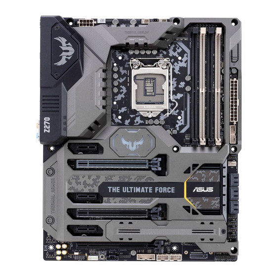
Package contents Check your motherboard package for the following items: ASUS TUF Z270 MARK 1 Technical documentations, Support DVD motherboard certification and warranty card 4 x Serial ATA 6.0 Gb/s cables 1 x SLI HB BRIDGE(2-WAY-M) 1 x ASUS Q-Shield…
-
Page 15: Installation Tools And Components
Installation tools and components Graphics card (optional) Phillips (cross) screwdriver PC chassis Power supply unit Intel LGA1151 CPU Intel LGA1151 compatible CPU Fan ® ® DIMM SATA hard disk drive SATA optical disc drive (optional) The tools and components in the table above are not included in the motherboard package.
-
Page 17: Chapter 1: Product Introduction
Chapter 1: Product Introduction Product Introduction Motherboard overview 1.1.1 Before you proceed Take note of the following precautions before you install motherboard components or change any motherboard settings. • Unplug the power cord from the wall socket before touching any component. • Before handling components, use a grounded wrist strap or touch a safely grounded object or a metal object, such as the power supply case, to avoid damaging them due to static electricity. • Hold components by the edges to avoid touching the ICs on them. • Whenever you uninstall any component, place it on a grounded antistatic pad or in the bag that came with the component. • Before you install or remove any component, ensure that the ATX power supply is switched off or the power cord is detached from the power supply. Failure to do so may cause severe damage to the motherboard, peripherals, or components. ASUS TUF Z270 MARK 1…
-
Page 18: Motherboard Layout
1.1.2 Motherboard layout Refer to 1.1.9 Internal connectors and 2.3.1 Rear I/O connection for more information about rear panel connectors and internal connectors. Chapter 1: Product Introduction…
-
Page 19: Layout Contents
7. USB 3.0 connector (20-1 pin USB3_34; USB3_56) 1-16 8. Intel Serial ATA 6 Gb/s connectors (7-pin SATA6G_12; SATA 6G_34; 1-14 ® SATA 6G_56) 9. System panel connector (20-3 pin PANEL) 1-20 10. M.2 sockets (M.2_1; M.2_2) 1-22 11. Clear RTC RAM jumper (2-pin CLRTC) 1-11 12. USB 2.0 connectors (10-1 pin USB1314; USB1112) 1-17 13. TPM connector (14-1 pin TPM) 1-21 14. Thunderbolt header (5-pin TB_HEADER) 1-17 15. Power-on button 16. Front panel audio connector (10-1 pin AAFP) 1-15 17. CPU Over Voltage jumper (3-pin CPU_OV) 1-12 ASUS TUF Z270 MARK 1…
-
Page 20: Central Processing Unit (Cpu)
1.1.3 Central Processing Unit (CPU) The motherboard comes with a surface mount LGA1151 socket designed for the 7th & 6th Generation Intel Core™ i7 / Intel Core™ i5 / Intel Core™ i3, Pentium , and Celeron ® ® ® ® ® processors. • Ensure that all power cables are unplugged before installing the CPU. • Upon purchase of the motherboard, ensure that the PnP cap is on the socket and the socket contacts are not bent. Contact your retailer immediately if the PnP cap is missing, or if you see any damage to the PnP cap/socket contacts/motherboard components. ASUS will shoulder the cost of repair only if the damage is shipment/ transit-related. • Keep the cap after installing the motherboard. ASUS will process Return Merchandise Authorization (RMA) requests only if the motherboard comes with the cap on the LGA1151 socket. • The product warranty does not cover damage to the socket contacts resulting from incorrect CPU installation/removal, or misplacement/loss/incorrect removal of the PnP cap. Chapter 1: Product Introduction…
-
Page 21: System Memory
1.1.4 System memory The motherboard comes with four DDR4 (Double Data Rate 4) Quad Inline Memory Modules (DIMM) slots. A DDR4 module is notched differently from a DDR, DDR2, or DDR3 module. DO NOT install a DDR, DDR2, or DDR3 memory module to the DDR4 slot. Recommended memory configurations ASUS TUF Z270 MARK 1…
-
Page 22: Memory Configurations
Memory configurations You may install 4 GB, 8 GB, and 16 GB unbuffered and non-ECC DDR4 DIMMs into the DIMM sockets. • Due to the memory address limitation on 32-bit Windows OS, when you install 4 GB ® or more memory on the motherboard, the actual usable memory for the OS can be about 3 GB or less. For effective use of memory, we recommend that you do any of the following: a) Use a maximum of 3GB system memory if you are using a 32-bit Windows OS. ® b) Install a 64-bit Windows OS when you want to install 4 GB or more on the ® motherboard. c) For more details, refer to the Microsoft ® support site at http://support.microsoft. com/kb/929605/en-us. • You may install varying memory sizes in Channel A and Channel B. The system maps the total size of the lower-sized channel for the dual-channel configuration. Any excess memory from the higher-sized channel is then mapped for single-channel operation. • The default memory operation frequency is dependent on its Serial Presence Detect (SPD), which is the standard way of accessing information from a memory module. Under the default state, some memory modules for overclocking may operate at a lower frequency than the vendor-marked value. • For system stability, use a more efficient memory cooling system to support a full memory load (4 DIMMs) or overclocking condition. • Always install the DIMMS with the same CAS Latency. For an optimum compatibility, we recommend that you install memory modules of the same version or data code (D/C) from the same vendor. Check with the vendor to get the correct memory modules.
-
Page 23: Expansion Slots
1.1.5 Expansion slots Unplug the power cord before adding or removing expansion cards. Failure to do so may cause you physical injury and damage motherboard components. Slot No. Slot Description PCIE 3.0/2.0 x1_1 slot PCIE 3.0/2.0 x16_1 slot PCIE 3.0/2.0 x1_2 slot PCIE 3.0/2.0 x16_2 slot PCIE 3.0/2.0 x1_3 slot PCIE 3.0/2.0 x16_3 slot ASUS TUF Z270 MARK 1…
-
Page 24: Irq Assignments For This Motherboard
PCI Express 3.0 operating mode VGA configuration PCIe 3.0/2.0 x16_1 PCIe 3.0/2.0 x16_2 PCIe 3.0/2.0 x16_3 x16 (single VGA Single VGA/PCIe card recommended) Dual VGA/PCIe card • We recommend that you provide sufficient power when running CrossFireX™ or SLI ® mode. • Connect chassis fans to the motherboard chassis fan connectors when using multiple graphics cards for better thermal environment. IRQ assignments for this motherboard PCIe X16_1 shared PCIe X16_2 shared PCIe X16_3 shared PCIe X1_1 shared PCIe X1_2 shared PCIe X1_3…
-
Page 25: Onboard Buttons And Switches
1.1.6 Onboard buttons and switches Onboard buttons and switches allow you to fine-tune performance when working on a bare or open-case system. This is ideal for overclockers and gamers who continually change settings to enhance system performance. Power-on button The motherboard comes with a power-on button that allows you to power up or wake up the system. The LED near the PCH also lights up when the system is plugged to a power source indicating that you should shut down the system and unplug the power cable before removing or installing any motherboard component. ASUS TUF Z270 MARK 1…
-
Page 26
MemOK! button lights continuously, press the MemOK! button until the DRAM_LED starts blinking. System will begin automatic memory compatibility tuning and reboot for successful boot. • Refer to section 1.1.8 Onboard LEDs for the exact location of the DRAM_LED. • The DRAM_LED also lights up when the DIMM is not properly installed. Turn off the system and reinstall the DIMM before using the MemOK! function. • The MemOK! button does not function under Windows OS environment. ® • During the tuning process, the system loads and tests failsafe memory settings. It takes about 30 seconds for the system to test one set of failsafe settings. If the test fails, the system reboots and tests the next set of failsafe settings. The blinking speed of the DRAM_LED increases, indicating different test processes. • Due to memory tuning requirement, the system automatically reboots when each timing set is tested. If the installed DIMMs still fail to boot after the whole tuning process, the DRAM_LED lights continuously. Replace the DIMMs with ones recommended in the Memory QVL (Qualified Vendors Lists) at www.asus.com. • If you turn off the computer and replace DIMMs during the tuning process, the system continues memory tuning after turning on the computer. To stop memory tuning, turn off the computer and unplug the power cord for about 5–10 seconds. • If your system fails to boot up due to BIOS overclocking, press the MemOK! button to boot and load the BIOS default settings. A message will appear during POST reminding you that the BIOS has been restored to its default settings. • We recommend that you download and update to the latest BIOS version from www.asus.com after using the MemOK! function. 1-10 Chapter 1: Product Introduction… -
Page 27: Jumpers
1.1.7 Jumpers Clear RTC RAM jumper (2-pin CLRTC) This jumper allows you to clear the Real Time Clock (RTC) RAM in CMOS. You can clear the CMOS memory of date, time, and system setup parameters by erasing the CMOS RTC RAM data. The onboard button cell battery powers the RAM data in CMOS, which include system setup information such as system passwords. To erase the RTC RAM: Turn OFF the computer and unplug the power cord. Short-circuit pin 1-2 with a metal object or jumper cap for about 5-10 seconds. Plug the power cord and turn ON the computer. Hold down the <Delete> key during the boot process and enter BIOS setup to re-enter data. Except when clearing the RTC RAM, never place a metal object or jumper cap on the CLRTC jumper. Placing a metal object or jumper cap will cause system boot failure! • If the steps above do not help, remove the onboard battery and place a metal object or jumper cap again to clear the CMOS RTC RAM data. After the CMOS clearance, reinstall the battery. • You do not need to clear the RTC when the system hangs due to overclocking. For system failure due to overclocking, use the C.P.R. (CPU Parameter Recall) feature. Shut down and reboot the system so the BIOS can automatically reset parameter settings to default values. • Due to the chipset behavior, AC power off is required to enable C.P.R. function. You must turn off and turn on the power supply or unplug and plug the power cord before rebooting the system. ASUS TUF Z270 MARK 1 1-11…
-
Page 28
CPU Over Voltage jumper (3-pin CPU_OV) The CPU Over Voltage jumper allows you to set a higher CPU voltage for a flexible overclocking system, depending on the type of the installed CPU. To gain more CPU voltage setting, insert the jumper to pins 2-3. To go back to its default CPU voltage setting, insert the jumper to pins 1-2. 1-12 Chapter 1: Product Introduction… -
Page 29: Onboard Leds
1.1.8 Onboard LEDs POST State LEDs The POST State LEDs provide the status of these key components during POST (Power-On Self-Test): CPU, memory modules, VGA card, and hard disk drives. If an error is found, the critical component’s LED stays lit up until the problem is solved. Standby Power LED The motherboard comes with a standby power LED. The LED lights up to indicate that the system is ON, in sleep mode, or in soft-off mode. This is a reminder that you should shut down the system and unplug the power cable before removing or plugging in any motherboard component. The illustration below shows the location of the onboard LED. ASUS TUF Z270 MARK 1 1-13…
-
Page 30: Internal Connectors
1.1.9 Internal connectors Intel Serial ATA 6 Gb/s connectors (7-pin SATA6G_12; SATA 6G_34; ® SATA 6G_56) These connectors connect to Serial ATA 6 Gb/s hard disk drives via Serial ATA 6 Gb/s signal cables. If you installed Serial ATA hard disk drives, you can create a RAID 0, 1, 5, and 10 configuration with the Intel Rapid Storage Technology through the onboard Intel ® ® Z270 chipset. • These connectors are set to [AHCI Mode] by default. If you intend to create a Serial ATA RAID set using these connectors, set the SATA Mode item in the BIOS to [Intel RST Premium With Intel Optane System Acceleration (RAID)]. • Before creating a RAID set, refer to the manual bundled in the motherboard support DVD. 1-14 Chapter 1: Product Introduction…
-
Page 31
Front panel audio connector (10-1 pin AAFP) This connector is for a chassis-mounted front panel audio I/O module that supports HD Audio. Connect one end of the front panel audio I/O module cable to this connector. We recommend that you connect a high-definition front panel audio module to this connector to avail of the motherboard’s high-definition audio capability. ASUS TUF Z270 MARK 1 1-15… -
Page 32
USB 3.0 connector (20-1 pin USB3_34; USB3_56) This connector allows you to connect a USB 3.0 module for additional USB 3.0 front or rear panel ports. With an installed USB 3.0 module, you can enjoy all the benefits of USB 3.0 including faster data transfer speeds of up to 5 Gb/s, faster charging time for USB-chargeable devices, optimized power efficiency, and backward compatibility with USB 2.0. The USB 3.0 module is purchased separately. • Ensure to install the related driver to fully use the USB 3.0 ports under Windows ® • The plugged USB 3.0 device may run on xHCI or EHCI mode depending on the operating system’s setting. 1-16 Chapter 1: Product Introduction… -
Page 33
Thunderbolt header (5-pin TB_HEADER) This connector is for the add-on Thunderbolt I/O card that supports Intel’s Thunderbolt Technology, allowing you to connect up to six Thunderbolt-enabled devices and a DisplayPort-enabled display in a daisy-chain configuration. The add-on Thunderbolt I/O card and Thunderbolt cables are purchased separately. USB 2.0 connectors (10-1 pin USB1314; USB1112) These connectors are for USB 2.0 ports. Connect the USB module cable to these connectors, then install the module to a slot opening at the back of the system chassis. This USB connector complies with USB 2.0 specification that supports up to 480 Mb/s connection speed. DO NOT connect a 1394 cable to the USB connectors. Doing so will damage the motherboard! The USB 2.0 module is purchased separately. ASUS TUF Z270 MARK 1 1-17… -
Page 34
CPU, water pump, high amp, CPU optional, assistant fan, extension, and chassis fan connectors (4-pin CPU_FAN; 4-pin W_PUMP+; 4-pin CPU_OPT; 5-pin EXT_ FAN; 4-pin H_AMP_FAN; 4-pin CHA_FAN1-5; 4-pin ASST_FAN) Connect the fan cables to the fan connectors on the motherboard. • DO NOT forget to connect the fan cables to the fan connectors. Insufficient air flow inside the system may damage the motherboard components. These are not jumpers! Do not place jumper caps on the fan connectors! • Ensure that the CPU FAN cable is securely installed to the CPU fan connector. • The CPU_FAN connector supports the CPU fan of maximum 1A (12 W) fan power. • The CPU_FAN, CHA_FAN and ASST_FAN connectors support the TUF Thermal Radar 2+ feature. -
Page 35
ATX power connectors (24-pin EATXPWR; 8-pin EATX12V) These connectors are for ATX power supply plugs. The power supply plugs are designed to fit these connectors in only one orientation. Find the proper orientation and push down firmly until the connectors completely fit. • For a fully configured system, we recommend that you use a power supply unit (PSU) that complies with ATX 12 V Specification 2.0 (or later version) and provides a minimum power of 350 W. • DO NOT forget to connect the 8-pin EATX12V power plug. Otherwise, the system will not boot. • We recommend that you use a PSU with a higher power output when configuring a system with more power-consuming devices. The system may become unstable or may not boot up if the power is inadequate. • If you want to use two or more high-end PCI Express x16 cards, use a PSU with 1000W power or above to ensure the system stability. ASUS TUF Z270 MARK 1 1-19… -
Page 36: System Panel Connector
System panel connector (20-3 pin PANEL) This connector supports several chassis-mounted functions. • System power LED (2-pin or 3-1 pin PLED) The 2-pin or 3-1 pin connector is for the system power LED. Connect the chassis power LED cable to this connector. The system power LED lights up when you turn on the system power, and blinks when the system is in sleep mode. • Hard disk drive activity LED (2-pin HDD_LED) This 2-pin connector is for the HDD Activity LED. Connect the HDD Activity LED cable to this connector. The HDD LED lights up or flashes when data is read from or written to the HDD. • System warning speaker (4-pin SPEAKER) This 4-pin connector is for the chassis-mounted system warning speaker. The speaker allows you to hear system beeps and warnings. • ATX power button/soft-off button (2-pin PWRSW) This connector is for the system power button. Pressing the power button turns the system on or puts the system in sleep or soft-off mode depending on the operating system settings. Pressing the power switch for more than four seconds while the system is ON turns the system OFF. • Reset button (2-pin RESET) This 2-pin connector is for the chassis-mounted reset button for system reboot without turning off the system power. • Chassis intrusion connector (2-pin CHASSIS) This connector is for a chassis-mounted intrusion detection sensor or switch. Connect one end of the chassis intrusion sensor or switch cable to this connector. The chassis intrusion sensor or switch sends a high-level signal to this connector when a chassis component is removed or replaced. The signal is then generated as a chassis intrusion event. 1-20 Chapter 1: Product Introduction…
-
Page 37
TPM connector (14-1 pin TPM) This connector supports a Trusted Platform Module (TPM) system, which securely stores keys, digital certificates, passwords and data. A TPM system also helps enhance network security, protect digital identities, and ensures platform integrity. The TPM module is purchased separately. Thermal sensor connectors (2-pin T_SENSOR1-3) These connectors are for the thermistor cable that monitors the temperature of the devices and the critical components inside the motherboard. Connect the thermistor cable and place the sensor on the device or the motherboard’s component to detect its temperature. ASUS TUF Z270 MARK 1 1-21… -
Page 38
11. M.2 sockets (M.2_1; M.2_2) These sockets allow you to install M.2 SSD modules. • M.2_1 socket supports PCIe 3.0 x4 and SATA mode M Key design and type 2242 / 2260 / 2280 / 22110 PCIe and SATA storage devices. • M.2_2 socket supports PCIe 3.0 x4 M Key design and type 2242 / 2260 / 2280 PCIe storage devices. • These sockets support IRST (Intel Rapid Storage Technology). ® The M.2 SSD module is purchased separately. 1-22 Chapter 1: Product Introduction… -
Page 39: Chapter 2: Basic Installation
2.1.1 IO Cover installation The ASUS TUF Z270 MARK 1 motherboard package can be installed with a 40 mm assistant fan for additional cooling solution and better airflow. To install the 40 mm assistant fan: Locate and remove the screw on the back I/O (A) then remove the back I/O fan cover lid (B).
-
Page 40
Align and insert the cover lid and the assistant fan assembly into the IO Cover and secure it with the screw that you removed in step 1. Ensure to tuck the fan cable inside the cable corner slot. Connect the fan cable connector to the assistant fan (ASST_FAN) header on the motherboard. -
Page 41: Motherboard Installation
2.1.2 Motherboard installation Install the ASUS Q-Shield to the chassis rear I/O panel. Place the motherboard into the chassis, ensuring that its rear I/O ports are aligned to the chassis’ rear I/O panel. ASUS TUF Z270 MARK 1…
-
Page 42
Place nine screws into the holes indicated by circles to secure the motherboard to the chassis. DO NOT overtighten the screws! Doing so can damage the motherboard. Chapter 2: Basic Installation… -
Page 43: Cpu Installation
Ensure that you install the correct CPU designed for LGA1151 socket only. DO NOT install a CPU designed for LGA1155 and LGA1156 sockets on the LGA1151 socket. Top of CPU Bottom of CPU Bottom of CPU ASUS TUF Z270 MARK 1…
-
Page 44
Always firmly hold both sides of the CPU Installation Tool when installing, removing, or picking up the CPU Installation Tool. • ASUS will not cover damages resulting from incorrect CPU installation/removal, incorrect CPU orientation/placement, or other damages resulting from negligence by the user. -
Page 45: Cpu Heatsink And Fan Assembly Installation
2.1.4 CPU heatsink and fan assembly installation Apply the Thermal Interface Material to the CPU heatsink and CPU before you install the heatsink and fan, if necessary. To install the CPU heatsink and fan assembly ASUS TUF Z270 MARK 1…
-
Page 46
To uninstall the CPU heatsink and fan assembly Chapter 2: Basic Installation… -
Page 47: Dimm Installation
2.1.5 DIMM installation To remove a DIMM ASUS TUF Z270 MARK 1…
-
Page 48: Atx Power Connection
2.1.6 ATX power connection Ensure to connect the 8-pin power plug. 2.1.7 SATA device connection Chapter 2: Basic Installation 2-10…
-
Page 49: Front I/O Connector
2.1.8 Front I/O connector To install ASUS Q-Connector To install USB 2.0 connector To install front panel audio connector AAFP USB 2.0 To install USB 3.0 connector USB 3.0 ASUS TUF Z270 MARK 1 2-11…
-
Page 50: Expansion Card Installation
2.1.9 Expansion Card installation To install PCIe x16 cards To install PCIe x1 cards Chapter 2: Basic Installation 2-12…
-
Page 51: M.2 Installation
2.1.10 M.2 installation Supported M.2 type varies per motherboard. ASUS TUF Z270 MARK 1 2-13…
-
Page 52: Bios Update Utility
• Updating BIOS may have risks. If the BIOS program is damaged during the process and results to the system’s failure to boot up, please contact your local ASUS Service Center. Chapter 2: Basic Installation…
-
Page 53: Motherboard Rear And Audio Connections
We strongly recommend that you connect your devices to ports with matching data transfer rate. Please connect your USB 3.0 devices to USB 3.0 ports and your USB 3.1 devices to USB 3.1 ports for faster and better performance for your devices. ASUS TUF Z270 MARK 1 2-15…
-
Page 54
* LAN ports LED indications Activity Link LED Speed LED Status Description Status Description ACT/LINK SPEED No link 10 Mbps connection Orange Linked Orange 100 Mbps connection Orange (Blinking) Data activity Green 1 Gbps connection Orange (Blinking Ready to wake up LAN port then steady) from S5 mode… -
Page 55: Audio I/O Connections
2.3.2 Audio I/O connections Audio I/O ports Connect to Headphone and Mic Connect to Stereo Speakers Connect to 2 Speakers ASUS TUF Z270 MARK 1 2-17…
-
Page 56
Connect to 4 Speakers Connect to 6 Speakers Connect to 8 Speakers Chapter 2: Basic Installation 2-18… -
Page 57: Starting Up For The First Time
While the system is ON, press the power button for less than four seconds to put the system on sleep mode or soft-off mode, depending on the BIOS setting. Press the power switch for more than four seconds to let the system enter the soft-off mode regardless of the BIOS setting. ASUS TUF Z270 MARK 1 2-19…
-
Page 58
Chapter 2: Basic Installation 2-20… -
Page 59: Chapter 3: Bios Setup
BIOS Setup Knowing BIOS The new ASUS UEFI BIOS is a Unified Extensible Interface that complies with UEFI architecture, offering a user-friendly interface that goes beyond the traditional keyboard- only BIOS controls to enable a more flexible and convenient mouse input. You can easily navigate the new UEFI BIOS with the same smoothness as your operating system.
-
Page 60: Bios Setup Program
BIOS setup program Use the BIOS Setup to update the BIOS or configure its parameters. The BIOS screen include navigation keys and brief onscreen help to guide you in using the BIOS Setup program. Entering BIOS at startup To enter BIOS Setup at startup, press <Delete> during the Power-On Self Test (POST). If you do not press <Delete>, POST continues with its routines.
-
Page 61: Ez Mode
Click to go to Advanced mode Loads optimized Search on the FAQ default settings Click to display boot devices Selects the boot device priority The boot device options vary depending on the devices you installed to the system. ASUS TUF Z270 MARK 1…
-
Page 62: Advanced Mode
3.2.2 Advanced Mode The Advanced Mode provides advanced options for experienced end-users to configure the BIOS settings. The figure below shows an example of the Advanced Mode. Refer to the following sections for the detailed configurations. To switch from EZ Mode to Advanced Mode, click Advanced Mode(F7) or press the <F7> hotkey.
-
Page 63: Menu Bar
This button above the menu bar allows you to view and tweak the overclocking settings of your system. It also allows you to change the motherboard’s SATA mode from AHCI to RAID mode. Refer to section 3.2.4 EZ Tuning Wizard for more information. ASUS TUF Z270 MARK 1…
-
Page 64: Hot Keys
Move your mouse over this button to show a QR code, scan this QR code on your mobile device to connect to the BIOS FAQ web page of the ASUS support website. You can also scan the following QR code: Hot keys This button above the menu bar contains the navigation keys for the BIOS setup program.
-
Page 65: Qfan Control
PWM Mode Select a profile to Click to apply the fan setting apply to your fans Click to undo the Click to go back to main menu changes Select to manually configure your fans ASUS TUF Z270 MARK 1…
-
Page 66
Configuring fans manually Select Manual from the list of profiles to manually configure your fans’ operating speed. Speed points Select to manually configure your fans To configure your fans: Select the fan that you want to configure and to view its current status. Click and drag the speed points to adjust the fans’… -
Page 67: Ez Tuning Wizard
To start OC Tuning: Press <F11> on your keyboard or click from the BIOS screen to open EZ Tuning Wizard screen. Click OC then click Next. Select a PC scenario Daily Computing or Gaming/Media Editing, then click Next. ASUS TUF Z270 MARK 1…
-
Page 68: Creating Raid
Select a Main Cooling System BOX cooler, Tower cooler, Water cooler, or I’m not sure, then click Next. After selecting the Main Cooling System, click Next then click Yes to start the OC Tuning. Creating RAID To create RAID: Press <F11> on your keyboard or click from the BIOS screen to open EZ Tuning Wizard screen.
-
Page 69
After selecting the type of RAID, click Next then click Yes to continue the RAID setup. After the RAID setup is done, click Yes to exit the setup then click OK to reset your system. ASUS TUF Z270 MARK 1 3-11… -
Page 70: My Favorites
My Favorites My Favorites is your personal space where you can easily save and access your favorite BIOS items. My Favorites comes with several performance, power saving, and fast boot related items by default. You can personalize this screen by adding or removing items. Chapter 3: BIOS Setup 3-12…
-
Page 71
Configuration items such as Memory SPD Information, system time and date. Click Exit (ESC) or press <Esc> key to close Setup Tree Map screen. Go to My Favorites menu to view the saved BIOS items. ASUS TUF Z270 MARK 1 3-13… -
Page 72: Main Menu
Main menu The Main menu screen appears when you enter the Advanced Mode of the BIOS Setup program. The Main menu provides you an overview of the basic system information, and allows you to set the system date, time, language, and security settings. Security The Security menu items allow you to change the system security settings.
-
Page 73: Dram Frequency
[Keep Current Settings] Keep the current settings without changing anything. [TPU I] Applies air cooling overclocking conditions. [TPU II] Applies water cooling overclocking conditions. Ensure to use water cooling device before selecting [TPU II]. ASUS TUF Z270 MARK 1 3-15…
-
Page 74: Advanced Menu
Internal CPU Power Management The subitems in this menu allow you to set the CPU ratio and features. Intel(R) SpeedStep(tm) Allows the operating system to dynamically adjust the processor voltage and cores frequency to decrease the average power consumption and decrease average heat production.
-
Page 75: Platform Misc Configuration
Serial ATA features that increases storage performance on random workloads by allowing the drive to internally optimize the order of commands. [RAID] Set to [RAID] when you want to create a RAID configuration from the SATA hard disk drives. ASUS TUF Z270 MARK 1 3-17…
-
Page 76: Pch-Fw Configuration
SMART Self Test SMART (Self-Monitoring, Analysis and Reporting Technology) is a monitoring system that shows a warning message during POST (Power-on Self Test) when an error occurs in the hard disks. Configuration options: [On] [Off] SATA6G_1(Gray) — SATA6G_6(Gray) SATA6G_1(Gray) — SATA6G_6(Gray) This item allows you to enable or disable the selected SATA port.
-
Page 77: Onboard Devices Configuration
This item allows you to turn the RGB LED lighting on or off. Configuration options: [On] [Off] Intel LAN Controller This item allows you to enable or disable the Intel LAN controllers. Configuration options: [Disabled] [Enabled] ASUS TUF Z270 MARK 1 3-19…
-
Page 78: Apm Configuration
3.6.9 APM Configuration The items in this menu allow you to set system wake and sleep settings. ErP Ready [Disabled] This item allows you to switch off some power at S4+S5 or S5 to get the system ready for ErP requirement. When set to [Enabled], all other PME options are switched off. Configuration options: [Disabled] [Enable(S4+S5)] [Enable(S5)] 3.6.10 Network Stack Configuration…
-
Page 79: Monitor Menu
Setup Mode [Advanced Mode] This item allows you to go to Advanced Mode of the BIOS after POST. [EZ Mode] This item allows you to go to EZ Mode of the BIOS after POST. ASUS TUF Z270 MARK 1 3-21…
-
Page 80: Secure Boot
CSM (Compatibility Support Module) This item allows you to configure the CSM (Compatibility Support Module) items to fully support the various VGA, bootable devices and add-on devices for better compatibility. Launch CSM [Auto] The system automatically detects the bootable devices and the add- on devices.
-
Page 81: Tool Menu
3.9.1 ASUS EZ Flash 3 Utility This item allows you to run ASUS EZ Flash 3. When you press <Enter>, a confirmation message appears. Use the left/right arrow key to select between [Yes] or [No], then press <Enter> to confirm your choice.
-
Page 82: Secure Erase
To launch Secure Erase, click Tool > Secure Erase on the Advanced mode menu. Check the ASUS support site for a full list of SSDs tested with Secure Erase. The drive may become unstable if you run Secure Erase on an incompatible SSD.
-
Page 83: Asus Overclocking Profile
This item displays the information and recommended configuration for the PCIE slots that the graphics card is installed in your system. This feature is only supported on selected ASUS graphics cards. Bus Interface This item allows you to select the bus interface.
-
Page 84: Exit Menu
3.10 Exit menu The Exit menu items allow you to load the optimal default values for the BIOS items, and save or discard your changes to the BIOS items. You can access the EZ Mode from the Exit menu. Load Optimized Defaults This option allows you to load the default values for each of the parameters on the Setup menus.
-
Page 85: Updating Bios
® ASUS EZ Flash 3: Updates the BIOS using a USB flash drive. ASUS CrashFree BIOS 3: Restores the BIOS using the motherboard support DVD or a USB flash drive when the BIOS file fails or gets corrupted. 3.11.1…
-
Page 86: Asus Ez Flash 3
3.11.2 ASUS EZ Flash 3 ASUS EZ Flash 3 allows you to download and update to the latest BIOS through the Internet without having to use a bootable floppy disk or an OS-based utility. Updating through the Internet varies per region and Internet conditions. Check your local Internet connection before updating through the Internet.
-
Page 87
To update the BIOS by Internet: Enter the Advanced Mode of the BIOS setup program. Go to the Tool menu to select ASUS EZ Flash Utility and press <Enter>. Select by Internet. Press the Left/Right arrow keys to select an Internet connection method, and then press <Enter>. -
Page 88: Asus Crashfree Bios 3
The BIOS file in the motherboard support DVD may be older than the BIOS file published on the ASUS official website. If you want to use the newer BIOS file, download the file at https://www.asus.com/support/ and save it to a USB flash drive.
-
Page 89: Chapter 4: Raid Support
With the RAID 10 configuration you get all the benefits of both RAID 0 and RAID 1 configurations. Use four new hard disk drives or use an existing drive and three new drives for this setup. ASUS TUF Z270 MARK 1…
-
Page 90: Installing Serial Ata Hard Disks
4.1.2 Installing Serial ATA hard disks The motherboard supports Serial ATA hard disk drives. For optimal performance, install identical drives of the same model and capacity when creating a disk array. To install the SATA hard disks for a RAID configuration: Install the SATA hard disks into the drive bays.
-
Page 91
When the RAID Level item is selected, press <Enter> to select the RAID level to create, and then press <Enter>. Under Select Disks, press <Enter> and select X for the disks you want to include in the RAID set. ASUS TUF Z270 MARK 1… -
Page 92
When the Strip Size item is selected, press <Enter> to select strip size for the RAID array (for RAID 0, 10 and 5 only), and then press <Enter>. The available strip size values range from 4 KB to 128 KB. The following are typical values: RAID 0: 128 KB RAID 10: 64 KB RAID 5: 64 KB… -
Page 93
<Enter>. The following screen appears: When the Delete item is selected, press <Enter>, then select Yes to delete the RAID volume and return to the Intel Rapid Storage Technology menu, or select No to ® cancel. ASUS TUF Z270 MARK 1… -
Page 94: Intel ® Rapid Storage Technology Option Rom Utility
4.1.4 Intel Rapid Storage Technology Option ROM utility ® To enter the Intel Rapid Storage Technology Option ROM utility: ® Turn on the system. During POST, press <Ctrl> + <I> to display the utility main menu. RAID Volumes: None defined. Physical Devices: Port Device Model…
-
Page 95
Size Status ST3160812AS 9LS0HJA4 149.0GB Non-RAID Disk ST3160812AS 9LS0F4HL 149.0GB Non-RAID Disk ST3160812AS 3LS0JYL8 149.0GB Non-RAID Disk ST3160812AS 9LS0BJ5H 149.0GB Non-RAID Disk Select 2 to 6 to use in creating the volume. [↑↓]-Prev/Next [SPACE]-SelectDisk [ENTER]-Done ASUS TUF Z270 MARK 1… -
Page 96
Use the up/down arrow key to select a drive, and then press <Space> to select. A small triangle marks the selected drive. Press <Enter> after completing your selection. Use the up/down arrow key to select the strip size for the RAID array (for RAID 0, 10 and 5 only), and then press <Enter>. -
Page 97
(This does not apply to Recovery volumes) Are you sure you want to delete “Volume0”? (Y/N): Press <Y> to delete the RAID set and return to the utility main menu, or press <N> to return to the DELETE VOLUME menu. ASUS TUF Z270 MARK 1… -
Page 98: Creating A Raid Driver Disk
Exiting the Intel Rapid Storage Technology Option ROM utility ® To exit the utility: From the utility main menu, select 6. Exit, then press <Enter>. The following warning message appears: [CONFIRM EXIT] Are you sure you want to exit? (Y/N): Press <Y>…
-
Page 99: Appendix
Consult the dealer or an experienced radio/TV technician for help. The use of shielded cables for connection of the monitor to the graphics card is required to assure compliance with FCC regulations. Changes or modifications to this unit not expressly approved by the party responsible for compliance could void the user’s authority to operate this equipment. ASUS TUF Z270 MARK 1…
-
Page 100: Canadian Department Of Communications Statement
IC: Canadian Compliance Statement Complies with the Canadian ICES-003 Class B specifications. This device complies with RSS 210 of Industry Canada. This Class B device meets all the requirements of the Canadian interference-causing equipment regulations. This device complies with Industry Canada license exempt RSS standard(s). Operation is subject to the following two conditions: (1) this device may not cause interference, and (2) this device must accept any interference, including interference that may cause undesired operation of the device.
-
Page 101
ASUS Recycling/Takeback Services ASUS recycling and takeback programs come from our commitment to the highest standards for protecting our environment. We believe in providing solutions for you to be able to responsibly recycle our products, batteries, other components as well as the packaging materials. -
Page 102
доступний на: www.asus.com/support Cijeli tekst EU izjave o sukladnosti dostupan je na: www.asus.com/support Türkçe AsusTek Computer Inc., bu aygıtın temel gereksinimlerle ve ilişkili Čeština Společnost ASUSTeK Computer Inc. tímto prohlašuje, že toto Yönergelerin diğer ilgili koşullarıyla uyumlu olduğunu beyan eder. -
Page 103: Asus Contact Information
+1-510-739-3777 +1-510-608-4555 Web site http://www.asus.com/us/ Technical Support Support fax +1-812-284-0883 Telephone +1-812-282-2787 Online support http://qr.asus.com/techserv ASUS COMPUTER GmbH (Germany and Austria) Address Harkort Str. 21-23, 40880 Ratingen, Germany +49-2102-959931 Web site http://www.asus.com/de Online contact http://eu-rma.asus.com/sales Technical Support Telephone +49-2102-5789555 Support Fax…
-
Page 104: Declaration Of Conformity
800 Corporate Way, Fremont Phone/Fax No: (510)739-3777/(510)608-4555 hereby declares that the product Product Name : Motherboard Model Number : TUF Z270 MARK 1 Conforms to the following specifications: FCC Part 15, Subpart B, Unintentional Radiators Supplementary Information: This device complies with part 15 of the FCC Rules. Operation is subject to the…
Инструкцию для ASUS TUF Z270 MARK 1 на русском языке, в формате pdf можно скачать с нашего сайта. Наш каталог предоставляем Вам инструкцию производителя фирмы ASUS, которая была взята из открытых источников. Ознакомившись с руководством по эксплуатации от ASUS, Вы на все 100% и правильно сможете воспользоваться всеми функциями устройства.
Для сохранения инструкции «Материнская плата ASUS TUF Z270 MARK 1» на русском языке на вашем компьютере либо телефоне, нажмите кнопку «Скачать инструкцию». Если активна кнопка «Инструкция онлайн», то Вы можете просмотреть документ (manual), в своём браузере онлайн.
Если у Вас нет возможности скачать инструкцию по эксплуатации либо просмотреть её, Вы можете поделиться ссылкой на эту страницу в социальных сетях и при удобном моменте скачать инструкцию. Либо добавьте эту страницу в закладки Вашего браузера, нажав кнопку «Добавить страницу в закладки браузера».
![]()
TUF Z270 MARK 1
Motherboard

E11891
First Edition
October 2016
Copyright© 2016 ASUSTeK COMPUTER INC. All Rights Reserved.
No part of this manual, including the products and software described in it, may be reproduced, transmitted, transcribed, stored in a retrieval system, or translated into any language in any form or by any means, except documentation kept by the purchaser for backup purposes, without the express written permission of ASUSTeK COMPUTER INC. (“ASUS”).
Product warranty or service will not be extended if: (1) the product is repaired, modified or altered, unless such repair, modification of alteration is authorized in writing by ASUS; or (2) the serial number of the product is defaced or missing.
ASUS PROVIDES THIS MANUAL “AS IS” WITHOUT WARRANTY OF ANY KIND, EITHER EXPRESS OR IMPLIED, INCLUDING BUT NOT LIMITED TO THE IMPLIED WARRANTIES OR CONDITIONS OF MERCHANTABILITY OR FITNESS FOR A PARTICULAR PURPOSE. IN NO EVENT SHALL ASUS, ITS DIRECTORS, OFFICERS, EMPLOYEES OR AGENTS BE LIABLE FOR ANY INDIRECT, SPECIAL, INCIDENTAL, OR CONSEQUENTIAL DAMAGES (INCLUDING DAMAGES FOR LOSS OF PROFITS, LOSS OF BUSINESS, LOSS OF USE OR DATA, INTERRUPTION OF BUSINESS AND THE LIKE), EVEN IF ASUS HAS BEEN ADVISED OF THE POSSIBILITY OF SUCH DAMAGES ARISING FROM ANY DEFECT OR ERROR IN THIS MANUAL OR PRODUCT.
SPECIFICATIONS AND INFORMATION CONTAINED IN THIS MANUAL ARE FURNISHED FOR INFORMATIONAL USE ONLY, AND ARE SUBJECT TO CHANGE AT ANY TIME WITHOUT NOTICE, AND SHOULD NOT BE CONSTRUED AS A COMMITMENT BY ASUS. ASUS ASSUMES NO RESPONSIBILITY OR LIABILITY FOR ANY ERRORS OR INACCURACIES THAT MAY APPEAR IN THIS MANUAL, INCLUDING THE PRODUCTS AND SOFTWARE DESCRIBED IN IT.
Products and corporate names appearing in this manual may or may not be registered trademarks or copyrights of their respective companies, and are used only for identification or explanation and to the owners’ benefit, without intent to infringe.
Offer to Provide Source Code of Certain Software
This product contains copyrighted software that is licensed under the General Public License (“GPL”), under the Lesser General Public License Version (“LGPL”) and/or other Free Open Source Software Licenses. Such software in this product is distributed without any warranty to the extent permitted by the applicable law. Copies of these licenses are included in this product.
Where the applicable license entitles you to the source code of such software and/or other additional data, you may obtain it for a period of three years after our last shipment of the product, either
(1)for free by downloading it from https://www.asus.com/support/
or
(2)for the cost of reproduction and shipment, which is dependent on the preferred carrier and the location where you want to have it shipped to, by sending a request to:
ASUSTeK Computer Inc.
Legal Compliance Dept.
15 Li Te Rd.,
Beitou, Taipei 112
Taiwan
In your request please provide the name, model number and version, as stated in the About Box of the product for which you wish to obtain the corresponding source code and your contact details so that we can coordinate the terms and cost of shipment with you.
The source code will be distributed WITHOUT ANY WARRANTY and licensed under the same license as the corresponding binary/object code.
This offer is valid to anyone in receipt of this information.
ASUSTeK is eager to duly provide complete source code as required under various Free Open Source Software licenses. If however you encounter any problems in obtaining the full corresponding source code we would be much obliged if you give us a notification to the email address gpl@asus.com, stating the product and describing the problem (please DO NOT send large attachments such as source code archives, etc. to this email address).
ii

Contents
|
Safety information………………………………………………………………………………………… |
vi |
|
About this guide…………………………………………………………………………………………… |
vii |
|
TUF Z270 MARK 1 specifications summary……………………………………………………. |
ix |
|
Package contents……………………………………………………………………………………….. |
xiv |
|
Installation tools and components………………………………………………………………… |
xv |
|
Chapter 1: |
Product Introduction |
||
|
1.1 |
Motherboard overview……………………………………………………………………. |
1-1 |
|
|
1.1.1 |
Before you proceed…………………………………………………………… |
1-1 |
|
|
1.1.2 |
Motherboard layout……………………………………………………………. |
1-2 |
|
|
1.1.3 |
Central Processing Unit (CPU)……………………………………………. |
1-4 |
|
|
1.1.4 |
System memory………………………………………………………………… |
1-5 |
|
|
1.1.5 |
Expansion slots…………………………………………………………………. |
1-7 |
|
|
1.1.6 |
Onboard buttons and switches……………………………………………. |
1-9 |
|
|
1.1.7 |
Jumpers…………………………………………………………………………. |
1-11 |
|
|
1.1.8 |
Onboard LEDs………………………………………………………………… |
1-13 |
|
|
1.1.9 |
Internal connectors………………………………………………………….. |
1-14 |
|
Chapter 2: |
Basic Installation |
||
|
2.1 |
Building your PC system………………………………………………………………… |
2-1 |
|
|
2.1.1 |
IO Cover installation………………………………………………………….. |
2-1 |
|
|
2.1.2 |
Motherboard installation…………………………………………………….. |
2-3 |
|
|
2.1.3 |
CPU installation………………………………………………………………… |
2-5 |
|
|
2.1.4 |
CPU heatsink and fan assembly installation………………………….. |
2-7 |
|
|
2.1.5 |
DIMM installation………………………………………………………………. |
2-9 |
|
|
2.1.6 |
ATX power connection……………………………………………………… |
2-10 |
|
|
2.1.7 |
SATA device connection…………………………………………………… |
2-10 |
|
|
2.1.8 |
Front I/O connector………………………………………………………….. |
2-11 |
|
|
2.1.9 |
Expansion Card installation………………………………………………. |
2-12 |
|
|
2.1.10 |
M.2 installation………………………………………………………………… |
2-13 |
|
|
2.2 |
BIOS update utility………………………………………………………………………… |
2-14 |
|
|
2.3 |
Motherboard rear and audio connections………………………………………. |
2-15 |
|
|
2.3.1 |
Rear I/O connection…………………………………………………………. |
2-15 |
|
|
2.3.2 |
Audio I/O connections………………………………………………………. |
2-17 |
|
|
2.4 |
Starting up for the first time………………………………………………………….. |
2-19 |
|
|
2.5 |
Turning off the computer………………………………………………………………. |
2-19 |
iii

|
Chapter 3: |
BIOS Setup |
||
|
3.1 |
Knowing BIOS………………………………………………………………………………… |
3-1 |
|
|
3.2 |
BIOS setup program……………………………………………………………………….. |
3-2 |
|
|
3.2.1 |
EZ Mode………………………………………………………………………….. |
3-3 |
|
|
3.2.2 |
Advanced Mode………………………………………………………………… |
3-4 |
|
|
3.2.3 |
QFan Control……………………………………………………………………. |
3-7 |
|
|
3.2.4 |
EZ Tuning Wizard……………………………………………………………… |
3-9 |
|
|
3.3 |
My Favorites…………………………………………………………………………………. |
3-12 |
|
|
3.4 |
Main menu……………………………………………………………………………………. |
3-14 |
|
|
3.5 |
Ai Tweaker menu………………………………………………………………………….. |
3-14 |
|
|
3.6 |
Advanced menu……………………………………………………………………………. |
3-16 |
|
|
3.6.1 |
CPU Configuration…………………………………………………………… |
3-16 |
|
|
3.6.2 |
Platform Misc Configuration………………………………………………. |
3-17 |
|
|
3.6.3 |
System Agent (SA) Configuration………………………………………. |
3-17 |
|
|
3.6.4 |
PCH Configuration…………………………………………………………… |
3-17 |
|
|
3.6.5 |
PCH Storage Configuration………………………………………………. |
3-17 |
|
|
3.6.6 |
PCH-FW Configuration…………………………………………………….. |
3-18 |
|
|
3.6.7 |
Thunderbolt(TM) Configuration………………………………………….. |
3-18 |
|
|
3.6.8 |
Onboard Devices Configuration…………………………………………. |
3-19 |
|
|
3.6.9 |
APM Configuration…………………………………………………………… |
3-20 |
|
|
3.6.10 |
Network Stack Configuration…………………………………………….. |
3-20 |
|
|
3.6.11 |
HDD/SSD SMART Information………………………………………….. |
3-20 |
|
|
3.6.12 |
USB Configuration…………………………………………………………… |
3-20 |
|
|
3.7 |
Monitor menu……………………………………………………………………………….. |
3-21 |
|
|
3.8 |
Boot menu……………………………………………………………………………………. |
3-21 |
|
|
3.9 |
Tool menu…………………………………………………………………………………….. |
3-23 |
|
|
3.9.1 |
ASUS EZ Flash 3 Utility……………………………………………………. |
3-23 |
|
|
3.9.2 |
Secure Erase………………………………………………………………….. |
3-24 |
|
|
3.9.3 |
ASUS Overclocking Profile……………………………………………….. |
3-25 |
|
|
3.9.4 |
ASUS SPD Information…………………………………………………….. |
3-25 |
|
|
3.9.5 |
Graphics Card Information………………………………………………… |
3-25 |
|
|
3.10 |
Exit menu……………………………………………………………………………………… |
3-26 |
|
|
3.11 |
Updating BIOS……………………………………………………………………………… |
3-27 |
|
|
3.11.1 |
EZ Update………………………………………………………………………. |
3-27 |
|
|
3.11.2 |
ASUS EZ Flash 3…………………………………………………………….. |
3-28 |
|
|
3.11.3 |
ASUS CrashFree BIOS 3…………………………………………………. |
3-30 |
iv

|
Chapter 4: |
RAID Support |
||
|
4.1 |
RAID configurations……………………………………………………………………….. |
4-1 |
|
|
4.1.1 |
RAID definitions………………………………………………………………… |
4-1 |
|
|
4.1.2 |
Installing Serial ATA hard disks…………………………………………… |
4-2 |
|
|
4.1.3 |
Intel® Rapid Storage Technology in UEFI BIOS…………………….. |
4-2 |
|
|
4.1.4 |
Intel® Rapid Storage Technology Option ROM utility………………. |
4-6 |
|
|
4.2 |
Creating a RAID driver disk…………………………………………………………… |
4-10 |
|
|
4.2.1 |
Creating a RAID driver disk in Windows® …………………………… |
4-10 |
|
|
Appendix |
|||
|
Notices |
……………………………………………………………………………………………………… |
A-1 |
|
|
ASUS contact information………………………………………………………………………….. |
A-5 |
v

Safety information
Electrical safety
•To prevent electrical shock hazard, disconnect the power cable from the electrical outlet before relocating the system.
•When adding or removing devices to or from the system, ensure that the power cables for the devices are unplugged before the signal cables are connected. If possible, disconnect all power cables from the existing system before you add a device.
•Before connecting or removing signal cables from the motherboard, ensure that all power cables are unplugged.
•Seek professional assistance before using an adapter or extension cord. These devices could interrupt the grounding circuit.
•Ensure that your power supply is set to the correct voltage in your area. If you are not sure about the voltage of the electrical outlet you are using, contact your local power company.
•If the power supply is broken, do not try to fix it by yourself. Contact a qualified service technician or your retailer.
Operation safety
•Before installing the motherboard and adding devices on it, carefully read all the manuals that came with the package.
•Before using the product, ensure all cables are correctly connected and the power cables are not damaged. If you detect any damage, contact your dealer immediately.
•To avoid short circuits, keep paper clips, screws, and staples away from connectors, slots, sockets and circuitry.
•Avoid dust, humidity, and temperature extremes. Do not place the product in any area where it may become wet.
•Place the product on a stable surface.
•If you encounter technical problems with the product, contact a qualified service technician or your retailer.
vi

About this guide
This user guide contains the information you need when installing and configuring the motherboard.
How this guide is organized
This guide contains the following parts:
1.Chapter 1: Product Introduction
This chapter describes the features of the motherboard and the new technology it supports. It includes description of the switches, jumpers, and connectors on the motherboard.
2.Chapter 2: Basic Installation
This chapter lists the hardware setup procedures that you have to perform when installing system components.
3.Chapter 3: BIOS Setup
This chapter tells how to change system settings through the BIOS Setup menus. Detailed descriptions of the BIOS parameters are also provided.
4.Chapter 4: RAID Support
This chapter describes the RAID configurations.
Where to find more information
Refer to the following sources for additional information and for product and software updates.
1.ASUS website
The ASUS website (www.asus.com) provides updated information on ASUS hardware and software products.
2.Optional documentation
Your product package may include optional documentation, such as warranty flyers, that may have been added by your dealer. These documents are not part of the standard package.
vii

Conventions used in this guide
To ensure that you perform certain tasks properly, take note of the following symbols used throughout this manual.
DANGER/WARNING: Information to prevent injury to yourself when trying to complete a task.
CAUTION: Information to prevent damage to the components when trying to complete a task.
IMPORTANT: Instructions that you MUST follow to complete a task.
NOTE: Tips and additional information to help you complete a task.
Typography
|
Bold text |
Indicates a menu or an item to select. |
|
Italics |
Used to emphasize a word or a phrase. |
|
<Key> |
Keys enclosed in the less-than and greater-than sign |
|
means that you must press the enclosed key. |
|
|
Example: <Enter> means that you must press the Enter or |
|
|
Return key. |
|
|
<Key1> + <Key2> + <Key3> |
If you must press two or more keys simultaneously, the key |
|
names are linked with a plus sign (+). |
viii

TUF Z270 MARK 1 specifications summary
|
LGA1151 socket for 7th & 6th Generation Intel® Core™ i7 / i5 / i3 / |
||
|
Pentium® /Celeron® Processors |
||
|
CPU |
Supports 14nm CPU |
|
|
Supports Intel® Turbo Boost Technology 2.0* |
||
|
* The support of these features depends on the CPU types. |
||
|
** Refer to www.asus.com for the complete CPU support list. |
||
|
Chipset |
Intel® Z270 Chipset |
|
|
4 x DIMM, max. 64GB DDR4 3866(O.C.) / 3733(O.C.) / 3600(O.C.) / |
||
|
3466(O.C.) / 3400(O.C.) / 3333(O.C.) / 3300(O.C.) / 3200(O.C.) |
||
|
/ 3000(O.C.) / 2800(O.C.) / 2666(O.C.) / 2400(O.C.) / 2133 MHz |
||
|
Non-ECC, Un-buffered Memory |
||
|
Dual channel memory architecture |
||
|
Memory |
Supports Intel® Extreme Memory Profile (XMP)* |
|
|
* Hyper DIMM support is subject to the physical characteristics of |
||
|
individual CPUs. Please refer to Memory QVL (Qualified Vendors List) |
||
|
for details. |
||
|
** Refer to www.asus.com for the complete Memory QVL (Qualified |
||
|
Vendors List). |
||
|
2 x PCI Express 3.0/2.0 x16 slots (single at x16 or dual at x8/x8 |
||
|
mode) |
||
|
Expansion slots |
1 x PCI Express 3.0/2.0 x16 slot (max. at x4 mode, compatible with |
|
|
PCIe x1, x2 and x4 devices) |
||
|
3 x PCI Express 3.0/2.0 x1 slots |
||
|
Integrated Graphics ProcessorIntel® HD Graphics support |
||
|
Multi-VGA output support: DisplayPort/HDMI port |
||
|
Supports DisplayPort 1.2* with max. resolution 4096 x 2304@60Hz |
||
|
VGA |
Supports HDMI 1.4b with max. resolution 4096 x 2160@24Hz |
|
|
Supports Intel® InTru™ 3D/Quick Sync Video/Clear Video HD |
||
|
Technology/Insider™ |
||
|
Maximum shared memory of 1024MB |
||
|
* DP 1.2 Multi-Stream Transport compliant, supports DP 1.2 monitor |
||
|
daisy chain up to 3 displays |
||
|
Multi-GPU support |
Supports NVIDIA® 2-Way/Quad-GPU SLI® Technology |
|
|
Supports AMD® 3-Way/Quad-GPU CrossFireX™ Technology |
||
|
Gigabit Intel LAN connection802.3az Energy Efficient Ethernet |
||
|
(EEE) appliance |
||
|
Intel® I219-V Gigabit LAN — Dual interconnect between the integrated |
||
|
LAN |
Media Access Controller (MAC) and physical layer (PHY) |
|
|
Intel® I211 Gigabit LAN controller |
||
|
TUF LANGuard |
||
|
ASUS Turbo LAN Utility |
||
|
(continued on the next page) |
ix

TUF Z270 MARK 1 specifications summary
Intel® Z270 Chipset with RAID 0, 1, 5, 10 and Intel Rapid Storage Technology 15 support
—1 x M.2_1 Socket 3 with M Key, type 2242/2260/2280/22110 storage devices support (both SATA & PCIE 3.0 x4 mode)*
—1 x Vertical M.2_2 Socket 3 with M Key, type 2242/2260/2280 storage devices support (PCIE 3.0 x4 mode)
—6 x SATA 6.0 Gb/s ports
—Ready for Intel® Optane Memory**
—Supports Intel® Smart Response Technology***
*The M.2_1 socket shares SATA_1 port when use M.2 SATA mode device. Adjust BIOS settings to use a SATA device.
**Intel® Optane Technology is only supported when using 7th Generation Intel® Processors. Before using Intel® Optane memory modules, ensure that you have updated your motherboard drivers and BIOS to the latest version from the ASUS support website.
***These functions will work depending on the CPU installed.
Realtek® S1220A 8-Channel High Definition Audio CODEC
—Power pre-regulator reduces power input noise to ensure consistent performance
—Separate layer for left and right track, ensuring both sound deliver equal quality
—Impedance sense for front and rear headphone outputs
—Audio shielding ensures precise analog/digital separation and greatly reduced multi-lateral interference
—Internal audio Amplifier to enhance the highest quality sound for headphone and speakers
—Unique de-pop circuit to reduce start-up popping noise to audio outputs
—Premium Japan-made audio capacitors provides warm, natural, and immersive sound with exceptional clarity and fidelity
—High quality 120dB SNR stereo playback output (Line-out@back) & 113dB SNR recording input (Line-in) support
—Supports up to 32-Bit/192kHz playback*
—DTS® HeadphoneX
—DTS® Connect
—Supports jack-detection, multi-streaming, front panel jackretasking (MIC)
—Optical S/PDIF out port at back I/O
*Due to limitations in HDA bandwidth, 32-Bit/192kHz is not supported for 8-Channel audio
Intel® Z270 Chipset
—6 x USB 3.0/2.0 ports (4 ports @mid-board, 2 port @back panel, blue)
—8 x USB 2.0/1.1 ports (4 ports @mid-board, 4 port @back panel, black)
ASMedia® USB 3.1 controller supports 3A power output
—1 x USB 3.1/3.0/2.0 port @back panel (teal blue, Type A)
—1 x USB 3.1/3.0/2.0 port @back panel (Type C)
(continued on the next page)
x
![]()
TUF Z270 MARK 1 specifications summary
|
“Ultimate COOL!” Thermal Solution |
||
|
— TUF Thermal Armor |
||
|
— TUF Thermal Radar 2+ |
||
|
— TUF ICe |
||
|
“We Got Your Back!” Shape Force |
||
|
— TUF Fortifier |
||
|
— ASUS SafeSlot |
||
|
“TUF ENGINE!” Power Design |
||
|
Exclusive TUF Features |
— 8+4 Digital Phase Power Design |
|
|
— TUF Components (10K Ti-Cap, TUF Chokes & MOSFET; certified |
||
|
by military-standard) |
||
|
— ASUS DIGI+ Power Control Utility |
||
|
“Safe & Stable!” Guardian Angel |
||
|
— TUF Detective 2 |
||
|
— TUF ESD Guards 2 |
||
|
— TUF LANGuard |
||
|
— MemOK! |
||
|
— USB BIOS Flashback with USB BIOS Flashback Wizard for EZ |
||
|
BIOS download scheduling |
||
|
— TPU with fast tuning |
||
|
— EPU |
||
|
— AURA Lighting Control and AURA Lighting Effects synchronization |
||
|
with compatible ASUS ROG devices. |
||
|
— ASUS UEFI BIOS EZ Mode featuring friendly graphics user |
||
|
interface |
||
|
— Turbo LAN to experience smooth online gaming with lower pings |
||
|
and less lags |
||
|
ASUS Features |
— AI Suite 3 |
|
|
— ASUS Q-Connector |
||
|
— ASUS Q-Shield |
||
|
— ASUS Q-LED (CPU, DRAM, VGA, Boot Device LED) |
||
|
— ASUS Q-Slot |
||
|
— ASUS Q-DIMM |
||
|
— ASUS O.C. Profile |
||
|
— ASUS CrashFree BIOS 3 |
||
|
— EZ Update |
||
|
— ASUS EZ Flash 3 |
||
|
— Multi-language BIOS |
||
|
(continued on the next page) |
xi

TUF Z270 MARK 1 specifications summary
|
1 x DisplayPort |
||
|
1 x HDMI port |
||
|
1 x TUF Detective USB port |
||
|
1 x USB BIOS Flashback Button |
||
|
1 x Optical S/PDIF out |
||
|
Back Panel I/O Ports |
2 x LAN (RJ45) ports |
|
|
1 x USB 3.1/3.0/2.0 port (teal blue, Type A) |
||
|
1 x USB 3.1/3.0/2.0 port (Type C) |
||
|
2 x USB 3.0/2.0 ports |
||
|
4 x USB 2.0/1.1 ports (black, one supports USB BIOS Flashback) |
||
|
8-channel Audio I/O ports |
||
|
2 x USB 3.0/2.0 connectors support additional 4 USB ports (19-pin) |
||
|
2 x USB 2.0/1/1 connectors support additional 4 USB ports |
||
|
1 x M.2_1 Socket 3 (for M Key, type 2242/2260/2280/22110 |
||
|
devices) |
||
|
1 x Vertical M.2_2 Socket 3 (for M Key, type 2242/2260/2280 |
||
|
devices) |
||
|
6 x SATA 6.0Gb/s connectors |
||
|
1 x CPU Fan connector (4-pin) for both 3-pin(DC mode) and |
||
|
4-pin(PWM mode) CPU coolers control with auto detection |
||
|
support |
||
|
1 x CPU OPT Fan connector (4-pin) |
||
|
1 x W_Pump+ header (4-pin) |
||
|
5 x Chassis Fan connectors (4-pin) for both 3-pin(DC mode) and |
||
|
4-pin(PWM mode) coolers control |
||
|
Internal I/O connectors |
1 x H_AMP_FAN (4-pin) for both 3-pin(DC mode) and 4-pin(PWM |
|
|
mode) control |
||
|
1 x Assistant Fan connectors (4-pin) |
||
|
1 x Front panel audio connector (AAFP) |
||
|
1 x S/PDIF out header |
||
|
1 x Thunderbolt header (5-pin) for ASUS ThunderboltEX series |
||
|
support |
||
|
1 x TPM connector |
||
|
1 x 24-pin EATX Power connector |
||
|
1 x 8-pin EATX 12V Power connector |
||
|
1 x System Panel(Q-Connector) |
||
|
1 x MemOK! button |
||
|
1 x Clear CMOS jumper |
||
|
3 x T_Sensor (Thermal Sensor) headers |
||
|
1 x 5-pin EXT_FAN(Extension Fan) connector |
||
|
(continued on the next page) |
xii

TUF Z270 MARK 1 specifications summary
|
128 Mb Flash ROM, UEFI AMI BIOS, PnP, DMI3.0, WfM2.0, SM |
||
|
BIOS 3.0, ACPI 6.0, Multi-language BIOS, ASUS EZ Flash 3, |
||
|
BIOS Features |
CrashFree BIOS 3, F11 EZ Tuning Wizard, F6 Qfan Control, F3 My |
|
|
Favorites, Last Modified log, F12 PrintScreen and ASUS DRAM |
||
|
SPD (Serial Presence Detect) memory information |
||
|
Manageability |
WfM 2.0, DMI 3.0, WOL by PME, PXE |
|
|
Drivers |
||
|
Support DVD contents |
ASUS Utilities |
|
|
EZ Update |
||
|
Anti-virus software (OEM version) |
||
|
Windows® 10 64-bit |
||
|
Operating System |
Windows® 8.1 64-bit* |
|
|
Windows® 7* |
||
|
Support |
||
|
* Windows® 8.1 64-bit and Windows® 7 32/64-bit are only supported when |
||
|
using 6th Generation Intel® Processors |
||
|
Form factor |
ATX Form Factor, 12”x 9.6” (30.5 cm x 24.4 cm) |
Specifications are subject to change without notice.
xiii

Package contents
Check your motherboard package for the following items:
|
Manual |
|||
|
User |
|||
|
ASUS TUF Z270 MARK 1 |
Technical documentations, |
Support DVD |
|
|
motherboard |
certification and warranty card |
||
|
4 x Serial ATA 6.0 Gb/s cables |
1 x SLI HB BRIDGE(2-WAY-M) |
1 x ASUS Q-Shield |
|
1 x Q-connector |
1 x CPU Installation Tool |
1 x M.2 screw package |
2 x PCIe x16 slot covers
1 x Vertical M.2 bracket set 1 x TUF Inside sticker 3 x PCIe x1 slot covers
•If any of the above items is damaged or missing, contact your retailer.
•The illustrated items above are for reference only. Actual product specifications may vary with different models.
xiv
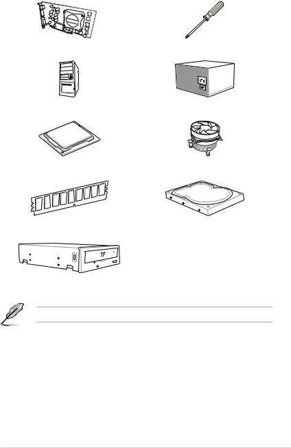
Installation tools and components
|
Graphics card (optional) |
Phillips (cross) screwdriver |
|
PC chassis |
Power supply unit |
|
Intel® LGA1151 CPU |
Intel® LGA1151 compatible CPU Fan |
|
DIMM |
SATA hard disk drive |
SATA optical disc drive (optional)
The tools and components in the table above are not included in the motherboard package.
xv

xvi

1.1Motherboard overview
1.1.1Before you proceed
Take note of the following precautions before you install motherboard components or change any motherboard settings.
•Unplug the power cord from the wall socket before touching any component.
•Before handling components, use a grounded wrist strap or touch a safely grounded object or a metal object, such as the power supply case, to avoid damaging them due to static electricity.
•Hold components by the edges to avoid touching the ICs on them.
•Whenever you uninstall any component, place it on a grounded antistatic pad or in the bag that came with the component.
•Before you install or remove any component, ensure that the ATX power supply is switched off or the power cord is detached from the power supply. Failure to do so may cause severe damage to the motherboard, peripherals, or components.
Chapter 1

1.1.2Motherboard layout
1 Chapter
Refer to 1.1.9 Internal connectors and 2.3.1 Rear I/O connection for more information about rear panel connectors and internal connectors.
|
1-2 |
Chapter 1: Product Introduction |

Layout contents
|
Connectors/Jumpers/Buttons and switches/Slots |
Page |
|
|
1. |
ATX power connectors (24-pin EATXPWR; 8-pin EATX12V) |
1-19 |
|
2. |
CPU, water pump, high amp, CPU optional, assistant fan, extension, |
1-18 |
|
and chassis fan connectors (4-pin CPU_FAN; 4-pin W_PUMP+; 4-pin |
||
|
CPU_OPT; 5-pin EXT_FAN; 4-pin H_AMP_FAN; 4-pin CHA_FAN1-5; |
||
|
4-pin ASST_FAN) |
||
|
3. |
LGA1151 CPU socket |
1-4 |
|
4. |
DDR4 DIMM slots |
1-5 |
|
5. |
MemOK! button |
1-10 |
|
6. |
Thermal sensor connectors (2-pin T_SENSOR1-3) |
1-21 |
|
7. |
USB 3.0 connector (20-1 pin USB3_34; USB3_56) |
1-16 |
|
8. |
Intel® Serial ATA 6 Gb/s connectors (7-pin SATA6G_12; SATA 6G_34; |
1-14 |
|
SATA 6G_56) |
||
|
9. |
System panel connector (20-3 pin PANEL) |
1-20 |
|
10. |
M.2 sockets (M.2_1; M.2_2) |
1-22 |
|
11. |
Clear RTC RAM jumper (2-pin CLRTC) |
1-11 |
|
12. |
USB 2.0 connectors (10-1 pin USB1314; USB1112) |
1-17 |
|
13. |
TPM connector (14-1 pin TPM) |
1-21 |
|
14. |
Thunderbolt header (5-pin TB_HEADER) |
1-17 |
|
15. |
Power-on button |
1-9 |
|
16. |
Front panel audio connector (10-1 pin AAFP) |
1-15 |
|
17. |
CPU Over Voltage jumper (3-pin CPU_OV) |
1-12 |
Chapter 1

1.1.3Central Processing Unit (CPU)
The motherboard comes with a surface mount LGA1151 socket designed for the 7th & 6th Generation Intel® Core™ i7 / Intel® Core™ i5 / Intel® Core™ i3, Pentium®, and Celeron® processors.
1 Chapter
•Ensure that all power cables are unplugged before installing the CPU.
•Upon purchase of the motherboard, ensure that the PnP cap is on the socket and the socket contacts are not bent. Contact your retailer immediately if the PnP cap is missing, or if you see any damage to the PnP cap/socket contacts/motherboard components. ASUS will shoulder the cost of repair only if the damage is shipment/ transit-related.
•Keep the cap after installing the motherboard. ASUS will process Return Merchandise Authorization (RMA) requests only if the motherboard comes with the cap on the LGA1151 socket.
•The product warranty does not cover damage to the socket contacts resulting from incorrect CPU installation/removal, or misplacement/loss/incorrect removal of the PnP cap.
|
1-4 |
Chapter 1: Product Introduction |
![]()
1.1.4System memory
The motherboard comes with four DDR4 (Double Data Rate 4) Quad Inline Memory Modules (DIMM) slots.
A DDR4 module is notched differently from a DDR, DDR2, or DDR3 module. DO NOT install a DDR, DDR2, or DDR3 memory module to the DDR4 slot.
Recommended memory configurations
Chapter 1

1 Chapter
Memory configurations
You may install 4 GB, 8 GB, and 16 GB unbuffered and non ECC DDR4 DIMMs into the DIMM sockets.
• Due to the memory address limitation on 32-bit Windows® OS, when you install 4 GB or more memory on the motherboard, the actual usable memory for the OS can be about 3 GB or less. For effective use of memory, we recommend that you do any of the following:
a)Use a maximum of 3GB system memory if you are using a 32-bit Windows® OS.
b)Install a 64-bit Windows® OS when you want to install 4 GB or more on the motherboard.
c)For more details, refer to the Microsoft® support site at http://support.microsoft. com/kb/929605/en-us.
•You may install varying memory sizes in Channel A and Channel B. The system maps the total size of the lower-sized channel for the dual-channel configuration. Any excess memory from the higher-sized channel is then mapped for single-channel operation.
• The default memory operation frequency is dependent on its Serial Presence Detect (SPD), which is the standard way of accessing information from a memory module. Under the default state, some memory modules for overclocking may operate at a lower frequency than the vendor-marked value.
•For system stability, use a more efficient memory cooling system to support a full memory load (4 DIMMs) or overclocking condition.
•Always install the DIMMS with the same CAS Latency. For an optimum compatibility, we recommend that you install memory modules of the same version or data code (D/C) from the same vendor. Check with the vendor to get the correct memory modules.
|
1-6 |
Chapter 1: Product Introduction |

1.1.5Expansion slots
Unplug the power cord before adding or removing expansion cards. Failure to do so may cause you physical injury and damage motherboard components.
Chapter 1
Slot No. Slot Description
1PCIE 3.0/2.0 x1_1 slot
2PCIE 3.0/2.0 x16_1 slot
3PCIE 3.0/2.0 x1_2 slot 4 PCIE 3.0/2.0 x16_2 slot 5 PCIE 3.0/2.0 x1_3 slot
6PCIE 3.0/2.0 x16_3 slot

1 Chapter
|
PCI Express 3.0 operating mode |
||||
|
VGA configuration |
||||
|
PCIe 3.0/2.0 x16_1 |
PCIe 3.0/2.0 x16_2 |
PCIe 3.0/2.0 x16_3 |
||
|
Single VGA/PCIe card |
x16 (single VGA |
N/A |
x4 |
|
|
recommended) |
||||
|
Dual VGA/PCIe card |
x8 |
x8 |
x4 |
•We recommend that you provide sufficient power when running CrossFireX™ or SLI® mode.
•Connect chassis fans to the motherboard chassis fan connectors when using multiple graphics cards for better thermal environment.
IRQ assignments for this motherboard
|
A |
B |
C |
D |
E |
F |
G |
H |
|
|
PCIe X16_1 |
shared |
|||||||
|
PCIe X16_2 |
shared |
|||||||
|
PCIe X16_3 |
shared |
|||||||
|
PCIe X1_1 |
shared |
|||||||
|
PCIe X1_2 |
shared |
|||||||
|
PCIe X1_3 |
shared |
|||||||
|
SMBUS Controller |
shared |
|||||||
|
SATA Controller |
shared |
|||||||
|
Intel LAN (I211) |
shared |
|||||||
|
Intel Lan (I219V) |
shared |
|||||||
|
ASMedia USB |
shared |
|||||||
|
Controller (2142) |
||||||||
|
Intel xHCI |
shared |
|||||||
|
HD Audio |
shared |
|
1-8 |
Chapter 1: Product Introduction |

1.1.6Onboard buttons and switches
Onboard buttons and switches allow you to fine-tune performance when working on a bare or open-case system. This is ideal for overclockers and gamers who continually change settings to enhance system performance.
|
1 |
||||||||||||||||||||||||||||||||||||||||||||||
|
1. |
Power-on button |
Chapter |
||||||||||||||||||||||||||||||||||||||||||||
|
The motherboard comes with a power-on button that allows you to power up or wake |
||||||||||||||||||||||||||||||||||||||||||||||
|
up the system. The LED near the PCH also lights up when the system is plugged to a |
||||||||||||||||||||||||||||||||||||||||||||||
|
power source indicating that you should shut down the system and unplug the power |
||||||||||||||||||||||||||||||||||||||||||||||
|
cable before removing or installing any motherboard component. |
||||||||||||||||||||||||||||||||||||||||||||||

|
2. MemOK! button |
||
|
Installing DIMMs that are not compatible with the motherboard may cause system boot |
||
|
failure. If the system fails to boot during POST stage and the DRAM_LED near the |
||
|
1Chapter |
MemOK! button lights continuously, press the MemOK! button until the DRAM_LED |
|
|
starts blinking. System will begin automatic memory compatibility tuning and reboot for |
||
|
successful boot. |
||
•Refer to section 1.1.8 Onboard LEDs for the exact location of the DRAM_LED.
•The DRAM_LED also lights up when the DIMM is not properly installed. Turn off the system and reinstall the DIMM before using the MemOK! function.
•The MemOK! button does not function under Windows® OS environment.
•During the tuning process, the system loads and tests failsafe memory settings. It takes about 30 seconds for the system to test one set of failsafe settings. If the test fails, the system reboots and tests the next set of failsafe settings. The blinking speed of the DRAM_LED increases, indicating different test processes.
•Due to memory tuning requirement, the system automatically reboots when each timing set is tested. If the installed DIMMs still fail to boot after the whole tuning process, the DRAM_LED lights continuously. Replace the DIMMs with ones recommended in the Memory QVL (Qualified Vendors Lists) at www.asus.com.
•If you turn off the computer and replace DIMMs during the tuning process, the system continues memory tuning after turning on the computer. To stop memory tuning, turn off the computer and unplug the power cord for about 5–10 seconds.
•If your system fails to boot up due to BIOS overclocking, press the MemOK! button to boot and load the BIOS default settings. A message will appear during POST reminding you that the BIOS has been restored to its default settings.
•We recommend that you download and update to the latest BIOS version from www.asus.com after using the MemOK! function.
|
1-10 |
Chapter 1: Product Introduction |
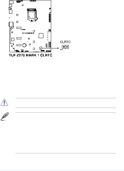
1.1.7Jumpers
|
1. Clear RTC RAM jumper (2-pin CLRTC) |
|||||||||||||||||||||||||||||||||||||||||
|
This jumper allows you to clear the Real Time Clock (RTC) RAM in CMOS. You can |
|||||||||||||||||||||||||||||||||||||||||
|
clear the CMOS memory of date, time, and system setup parameters by erasing the |
1 |
||||||||||||||||||||||||||||||||||||||||
|
CMOS RTC RAM data. The onboard button cell battery powers the RAM data in |
|||||||||||||||||||||||||||||||||||||||||
|
Chapter |
|||||||||||||||||||||||||||||||||||||||||
|
CMOS, which include system setup information such as system passwords. |
|||||||||||||||||||||||||||||||||||||||||
To erase the RTC RAM:
1.Turn OFF the computer and unplug the power cord.
2.Short-circuit pin 1-2 with a metal object or jumper cap for about 5-10 seconds.
3.Plug the power cord and turn ON the computer.
4.Hold down the <Delete> key during the boot process and enter BIOS setup to re-enter data.
Except when clearing the RTC RAM, never place a metal object or jumper cap on the
CLRTC jumper. Placing a metal object or jumper cap will cause system boot failure!
•If the steps above do not help, remove the onboard battery and place a metal object or jumper cap again to clear the CMOS RTC RAM data. After the CMOS clearance, reinstall the battery.
•You do not need to clear the RTC when the system hangs due to overclocking. For system failure due to overclocking, use the C.P.R. (CPU Parameter Recall) feature. Shut down and reboot the system so the BIOS can automatically reset parameter settings to default values.
•Due to the chipset behavior, AC power off is required to enable C.P.R. function. You must turn off and turn on the power supply or unplug and plug the power cord before rebooting the system.
|
ASUS TUF Z270 MARK 1 |
1-11 |

|
2. |
CPU Over Voltage jumper (3-pin CPU_OV) |
|
The CPU Over Voltage jumper allows you to set a higher CPU voltage for a flexible |
|
|
overclocking system, depending on the type of the installed CPU. To gain more CPU |
|
|
1 Chapter |
voltage setting, insert the jumper to pins 2-3. To go back to its default CPU voltage |
|
setting, insert the jumper to pins 1-2. |
|
|
1-12 |
Chapter 1: Product Introduction |

1.1.8Onboard LEDs
|
1. |
POST State LEDs |
|
|
The POST State LEDs provide the status of these key components during POST |
||
|
(Power-On Self-Test): CPU, memory modules, VGA card, and hard disk drives. If an |
1 |
|
|
error is found, the critical component’s LED stays lit up until the problem is solved. |
||
|
Chapter |
||
2.Standby Power LED
The motherboard comes with a standby power LED. The LED lights up to indicate that the system is ON, in sleep mode, or in soft-off mode. This is a reminder that you should shut down the system and unplug the power cable before removing or plugging in any motherboard component. The illustration below shows the location of the onboard LED.
|
ASUS TUF Z270 MARK 1 |
1-13 |

|
1.1.9 |
Internal connectors |
|||||||||||||||||||||||||||||||||||||||||||||||
|
1. Intel® Serial ATA 6 Gb/s connectors (7-pin SATA6G_12; SATA 6G_34; |
||||||||||||||||||||||||||||||||||||||||||||||||
|
SATA 6G_56) |
||||||||||||||||||||||||||||||||||||||||||||||||
|
Chapter |
These connectors connect to Serial ATA 6 Gb/s hard disk drives via Serial ATA 6 Gb/s |
|||||||||||||||||||||||||||||||||||||||||||||||
|
Z270 chipset. |
||||||||||||||||||||||||||||||||||||||||||||||||
|
signal cables. |
||||||||||||||||||||||||||||||||||||||||||||||||
|
If you installed Serial ATA hard disk drives, you can create a RAID 0, 1, 5, and 10 |
||||||||||||||||||||||||||||||||||||||||||||||||
|
configuration with the Intel® Rapid Storage Technology through the onboard Intel® |
||||||||||||||||||||||||||||||||||||||||||||||||
|
1 |
||||||||||||||||||||||||||||||||||||||||||||||||
These connectors are set to [AHCI Mode] by default. If you intend to create a Serial ATA RAID set using these connectors, set the SATA Mode item in the BIOS to [Intel RST Premium With Intel Optane System Acceleration (RAID)].
Before creating a RAID set, refer to the manual bundled in the motherboard support DVD.
|
1-14 |
Chapter 1: Product Introduction |
![]()
2.Front panel audio connector (10-1 pin AAFP)
This connector is for a chassis-mounted front panel audio I/O module that supports HD Audio. Connect one end of the front panel audio I/O module cable to this connector.
Chapter 1
We recommend that you connect a high-definition front panel audio module to this connector to avail of the motherboard’s high-definition audio capability.
|
ASUS TUF Z270 MARK 1 |
1-15 |

|
3. |
USB 3.0 connector (20-1 pin USB3_34; USB3_56) |
|||||||||||||||||||||||||||||||||||||||||||||||||||||||||||||||||
|
This connector allows you to connect a USB 3.0 module for additional USB 3.0 front |
||||||||||||||||||||||||||||||||||||||||||||||||||||||||||||||||||
|
or rear panel ports. With an installed USB 3.0 module, you can enjoy all the benefits of |
||||||||||||||||||||||||||||||||||||||||||||||||||||||||||||||||||
|
1Chapter |
USB 3.0 including faster data transfer speeds of up to 5 Gb/s, faster charging time for |
|||||||||||||||||||||||||||||||||||||||||||||||||||||||||||||||||
|
USB-chargeable devices, optimized power efficiency, and backward compatibility with |
||||||||||||||||||||||||||||||||||||||||||||||||||||||||||||||||||
|
USB 2.0. |
||||||||||||||||||||||||||||||||||||||||||||||||||||||||||||||||||
The USB 3.0 module is purchased separately.
•Ensure to install the related driver to fully use the USB 3.0 ports under Windows® 7.
•The plugged USB 3.0 device may run on xHCI or EHCI mode depending on the operating system’s setting.
|
1-16 |
Chapter 1: Product Introduction |
 Loading…
E11891
First Edition
October 2016
Copyright© 2016 ASUSTeK COMPUTER INC. All Rights Reserved.
No part of this manual, including the products and software described in it, may be reproduced,
transmitted, transcribed, stored in a retrieval system, or translated into any language in any form or by any
means, except documentation kept by the purchaser for backup purposes, without the express written
permission of ASUSTeK COMPUTER INC. («ASUS»).
Product warranty or service will not be extended if: (1) the product is repaired, modified or altered, unless
such repair, modification of alteration is authorized in writing by ASUS; or (2) the serial number of the
product is defaced or missing.
ASUS PROVIDES THIS MANUAL «AS IS» WITHOUT WARRANTY OF ANY KIND, EITHER EXPRESS
OR IMPLIED, INCLUDING BUT NOT LIMITED TO THE IMPLIED WARRANTIES OR CONDITIONS OF
MERCHANTABILITY OR FITNESS FOR A PARTICULAR PURPOSE. IN NO EVENT SHALL ASUS, ITS
DIRECTORS, OFFICERS, EMPLOYEES OR AGENTS BE LIABLE FOR ANY INDIRECT, SPECIAL,
INCIDENTAL, OR CONSEQUENTIAL DAMAGES (INCLUDING DAMAGES FOR LOSS OF PROFITS,
LOSS OF BUSINESS, LOSS OF USE OR DATA, INTERRUPTION OF BUSINESS AND THE LIKE),
EVEN IF ASUS HAS BEEN ADVISED OF THE POSSIBILITY OF SUCH DAMAGES ARISING FROM ANY
DEFECT OR ERROR IN THIS MANUAL OR PRODUCT.
SPECIFICATIONS AND INFORMATION CONTAINED IN THIS MANUAL ARE FURNISHED FOR
INFORMATIONAL USE ONLY, AND ARE SUBJECT TO CHANGE AT ANY TIME WITHOUT NOTICE,
AND SHOULD NOT BE CONSTRUED AS A COMMITMENT BY ASUS. ASUS ASSUMES NO
RESPONSIBILITY OR LIABILITY FOR ANY ERRORS OR INACCURACIES THAT MAY APPEAR IN THIS
MANUAL, INCLUDING THE PRODUCTS AND SOFTWARE DESCRIBED IN IT.
Products and corporate names appearing in this manual may or may not be registered trademarks or
copyrights of their respective companies, and are used only for identification or explanation and to the
owners’ benefit, without intent to infringe.
Offer to Provide Source Code of Certain Software
This product contains copyrighted software that is licensed under the General Public License («GPL»),
under the Lesser General Public License Version («LGPL») and/or other Free Open Source Software
Licenses. Such software in this product is distributed without any warranty to the extent permitted by the
applicable law. Copies of these licenses are included in this product.
Where the applicable license entitles you to the source code of such software and/or other additional data,
you may obtain it for a period of three years after our last shipment of the product, either
(1) for free by downloading it from https://www.asus.com/support/
or
(2) for the cost of reproduction and shipment, which is dependent on the preferred carrier and the location
where you want to have it shipped to, by sending a request to:
ASUSTeK Computer Inc.
Legal Compliance Dept.
15 Li Te Rd.,
Beitou, Taipei 112
Taiwan
In your request please provide the name, model number and version, as stated in the About Box of the
product for which you wish to obtain the corresponding source code and your contact details so that we
can coordinate the terms and cost of shipment with you.
The source code will be distributed WITHOUT ANY WARRANTY and licensed under the same license as
the corresponding binary/object code.
This offer is valid to anyone in receipt of this information.
ASUSTeK is eager to duly provide complete source code as required under various Free Open Source
Software licenses. If however you encounter any problems in obtaining the full corresponding source
code we would be much obliged if you give us a notification to the email address gpl@asus.com, stating
the product and describing the problem (please DO NOT send large attachments such as source code
archives, etc. to this email address).
ii
|
Detail Specifications: 1035/1035034-tuf_z270_mark_1.pdf file (20 Nov 2022) |
Accompanying Data:
Asus TUF Z270 Mark 1 Motherboard, Motherboards PDF Operation & User’s Manual (Updated: Sunday 20th of November 2022 06:44:50 AM)
Rating: 4.3 (rated by 45 users)
Compatible devices: INTEL CUW(E)-FX, B85M-D Plus, P4B266-C, P4T-E, NCCH-DR, Republic Of Gamers ROG STRIX B550-I GAMING, M4N78-AM V2, H81-M2.
Recommended Documentation:
Text Version of Operation & User’s Manual
(Ocr-Read Summary of Contents, UPD: 20 November 2022)
Recommended Instructions:
XL-ICA-311, EasySteamPlus 10 GN 1/1, WF18, 5117, 2011 Colorado, UMC5200AA


-
March 2012 Doc ID 022592 Rev 1 1/29UM1499User manualEVALSP320SCPU evaluation board for SPEAr320SIntroductionThis document applies to revision 2.0 SPEAr320S CPU evaluation boards.This board can be used to evaluate SPEAr320S microprocessors; the evaluation board kit comprises one board, one serial cable interface, and one power supply.CPU board features■ SPEAr320S embedded MPU� …
EVALSP320SCPU 29
-
A13-OLinuXino and A13-OLinuXino-WIFIOpen-source single-boardAndroid 4.0 mini-computerUSER’S MANUALRevision F, March 2013Designed by OLIMEX Ltd, 2012All boards produced by Olimex LTD are ROHS compliantElcodis.com electronic components distributor …
A13-OLinuXino 37
-
User’s GuideTPS62869EVM-118 Evaluation ModuleABSTRACTThis user’s guide describes the characteristics, operation, and use of TI’s evaluation module (EVM) for the TPS628691, TPS628692, TPS628681, TPS628682 devices. The TPS62869EVM-118 (BSR118) facilitates the evaluation of the TPS62869 family of 6-A, step-down converter with DCS-Control™in a small 1.5-mm …
TPS62869EVM-118 15