- Инструкции и руководства
- Бренды
- ASUS
- Z97-A
- Справочник Пользователя
![]()
-
Драйверы
36
-
Инструкции по эксплуатации
6
Языки:

ASUS Z97-A инструкция по эксплуатации
(28 страниц)
- Языки:Русский
-
Тип:
PDF -
Размер:
1.27 MB -
Описание:
Z97 Series Exclusion Feature Manual (Russian)
Z97 Series Exclusion Feature Manual (Russian)
Просмотр

ASUS Z97-A инструкция по эксплуатации
(28 страниц)
- Языки:Японский
-
Тип:
PDF -
Размер:
2.46 MB -
Описание:
Z97 Series Exclusive Features User’s Manual (Japanese)
Z97 Series Exclusive Features User’s Manual (Japanese)
Просмотр

ASUS Z97-A инструкция по эксплуатации
(28 страниц)
- Языки:Немецкий
-
Тип:
PDF -
Размер:
2.75 MB -
Описание:
Z97 Series Exclusive Features user’s manual(German)
Z97 Series Exclusive Features user’s manual(German)
Просмотр

ASUS Z97-A инструкция по эксплуатации
(121 страница)
- Языки:Французский
-
Тип:
PDF -
Размер:
6.7 MB -
Описание:
Z97-A user’s manual(French)
Z97-A user’s manual(French)
Просмотр

ASUS Z97-A инструкция по эксплуатации
(114 страниц)
- Языки:Немецкий
-
Тип:
PDF -
Размер:
5.78 MB -
Описание:
Z97-A user’s manual(German)
Z97-A user’s manual(German)
Просмотр

ASUS Z97-A инструкция по эксплуатации
(116 страниц)
- Языки:Японский
-
Тип:
PDF -
Размер:
6.08 MB -
Описание:
Z97-A User’s Manual (Japanese)
Z97-A User’s Manual (Japanese)
Просмотр
На NoDevice можно скачать инструкцию по эксплуатации для ASUS Z97-A. Руководство пользователя необходимо для ознакомления с правилами установки и эксплуатации ASUS Z97-A. Инструкции по использованию помогут правильно настроить ASUS Z97-A, исправить ошибки и выявить неполадки.
Посмотреть инструкция для Asus Z97-A бесплатно. Руководство относится к категории материнские платы, 4 человек(а) дали ему среднюю оценку 8.7. Руководство доступно на следующих языках: английский. У вас есть вопрос о Asus Z97-A или вам нужна помощь? Задайте свой вопрос здесь
Не можете найти ответ на свой вопрос в руководстве? Вы можете найти ответ на свой вопрос ниже, в разделе часто задаваемых вопросов о Asus Z97-A.
Какая толщина Asus Z97-A?
Инструкция Asus Z97-A доступно в русский?
Не нашли свой вопрос? Задайте свой вопрос здесь
- Manuals
- Brands
- Asus Manuals
- Motherboard
- Z97-A/USB 3.1
- User manual
-
Contents
-
Table of Contents
-
Bookmarks
Quick Links
Related Manuals for Asus Z97-A/USB 3.1
Summary of Contents for Asus Z97-A/USB 3.1
-
Page 1
Z97-A/ USB 3.1… -
Page 2
Product warranty or service will not be extended if: (1) the product is repaired, modified or altered, unless such repair, modification of alteration is authorized in writing by ASUS; or (2) the serial number of the product is defaced or missing. -
Page 3: Table Of Contents
Contents Safety information …………………. iv About this guide ………………….iv Package contents ………………….. vi Z97-A/USB 3.1 specifications summary …………..vi Chapter 1: Product Introduction Before you proceed ………………. 1-1 Motherboard overview …………….1-1 Central Processing Unit (CPU) …………..1-4 System memory ………………1-7 Expansion slots ………………
-
Page 4: Safety Information
Safety information Electrical safety • To prevent electrical shock hazard, disconnect the power cable from the electrical outlet before relocating the system. • When adding or removing devices to or from the system, ensure that the power cables for the devices are unplugged before the signal cables are connected. If possible, disconnect all power cables from the existing system before you add a device.
-
Page 5: Conventions Used In This Guide
Refer to the following sources for additional information and for product and software updates. ASUS websites The ASUS website provides updated information on ASUS hardware and software products. Refer to the ASUS contact information. Optional documentation Your product package may include optional documentation, such as warranty flyers, that may have been added by your dealer.
-
Page 6: Package Contents
Package contents Check your motherboard package for the following items: ASUS Z97-A/USB 3.1 Motherboard Motherboard 3 x Serial ATA 6.0 Gb/s cables Cables 1 x ASUS SLI bridge connector Accessories 2-in-1 Q-connector Support DVD Application DVD User Guide Documentation If any of the above items is damaged or missing, contact your retailer.
-
Page 7
— Supports jack-detection, multi-streaming and front panel jack-retasking (MIC) — Optical S/PDIF out port at rear I/O ASMedia USB 3.1 controller — supports ASUS USB 3.1 Boost ® — 2 x USB 3.1/3.0/2.0 ports at rear panel (teal blue) Intel Z97 Express Chipset — supports ASUS USB 3.0 Boost… -
Page 8
Z97-A/USB 3.1 specifications summary DIGI+ Power Control — CPU Power — Industry-leading digital 8-phase power design — ASUS CPU power utility — Auto Tuning, TPU, GPU Boost, 2-level TPU switch — EPU, EPU switch Fan Xpert 3 — Featuring Fan Auto Tuning function and multiple thermistors selection for… -
Page 9
— O.C. Tuner Features — CrashFree BIOS 3 — EZ Flash 2 ASUS Q-Design — ASUS Q-LED (CPU, DRAM, VGA, Boot Device LED) — ASUS Q-Slot — ASUS Q-DIMM — ASUS Q-Connector 5X Protection featuring all-round protection provides the best quality, reliability, and durability USB 3.1 Boost… -
Page 10
Front panel audio connector (AAFP) 64 Mb Flash ROM, UEFI AMI BIOS, PnP, DMI 2.7, WfM 2.0, SM BIOS 2.8, ACPI 5.0, Multi-language BIOS, ASUS EZ Flash 2, ASUS CrashFree BIOS 3, My BIOS features Favorites, Quick Note, Last Modified log, F12 PrintScreen, F3 Shortcut function, and ASUS DRAM SPD (Serial Presence Detect) memory information WfM 2.0, DMI 2.7, WOL by PME, PXE… -
Page 11: Chapter 1: Product Introduction
1.2.2 Screw holes Place nine screws into the holes indicated by circles to secure the motherboard to the chassis. Do not overtighten the screws! Doing so can damage the motherboard. ASUS Z97-A/USB 3.1…
-
Page 12: Motherboard Layout
Place this side towards the rear of the chassis 1.2.3 Motherboard layout Chapter 1: Product introduction…
-
Page 13: Layout Contents
TPM connector (20-1 pin TPM) 1-32 Power-on button 1-42 Thunderbolt header (5-pin TB_HEADER) 1-35 Serial port connector (10-1 pin COM) 1-27 Front panel audio connector (10-1 pin AAFP) 1-30 Digital audio connector (4-1 pin SPDIF_OUT) 1-30 M.2 Socket 3 1-31 ASUS Z97-A/USB 3.1…
-
Page 14: Central Processing Unit (Cpu)
Contact your retailer immediately if the PnP cap is missing, or if you see any damage to the PnP cap/socket contacts/motherboard components. ASUS will shoulder the cost of repair only if the damage is shipment/ transit-related.
-
Page 15: Installing The Cpu
1.3.1 Installing the CPU ASUS Z97-A/USB 3.1…
-
Page 16: Cpu Heatsink And Fan Assembly Installation
1.3.2 CPU heatsink and fan assembly installation Apply the Thermal Interface Material to the CPU heatsink and CPU before you install the heatsink and fan, if necessary. To install the CPU heatsink and fan assembly Chapter 1: Product introduction…
-
Page 17: System Memory
(DIMM) sockets. A DDR3 module is notched differently from a DDR or DDR2 module. DO NOT install a DDR or DDR2 memory module to the DDR3 slot. According to Intel CPU spec, DIMM voltage below 1.65 V is recommended to protect the ® CPU. ASUS Z97-A/USB 3.1…
-
Page 18: Recommended Memory Configurations
The stability and compatibility of the memory modules depend on the CPU’s capabilities and other installed devices. • For system stability, use a more efficient memory cooling system to support a full memory load (4 DIMMs). • Visit the ASUS website at: www.asus.com for the latest QVL. Chapter 1: Product introduction…
-
Page 19
Z97-A/USB 3.1 Motherboard Qualified Vendors Lists (QVL) DDR3 3200 (O.C.) MHz capability Vendors Part No. Size SS/DS Chip Chip Timing Voltage DIMM socket Brand support (Optional) AVEXIR AVD3UH32001304G-4CI(XMP) 16GB (4x4GB) 13-15-15-35 1.65V • • • G.SKILL F3-3200C12Q-16GTXDG(XMP) 16GB (4x4GB) 12-15-15-35 1.65V… -
Page 20
DDR3 2800 (O.C.) MHz capability Vendors Part No. Size SS/DS Chip Chip Timing Voltage DIMM socket Brand support (Optional) AVEXIR AVD3UH28001208G- 32GB (4x8GB) 12-14-14-35 1.65V • • • 4BZ1(XMP) A-DATA AX3U2800W 16GB (4x4GB) 12-14-14-36 1.65V • • • 4G12(XMP) A-DATA AX3U2800W 32GB (4x8GB) 12-14-14-36… -
Page 21
• • • 64GBZHD(XMP) G.SKILL F3-19200CL10Q- 32GB (4x8GB) 10-12-12-31 1.65 • • 32GBZHD(XMP) G.SKILL F3-19200CL11Q- 16GB (4x4GB) 11-11-11-31 1.65 • • • 16GBZHD(XMP) G.SKILL F3-19200CL9D-4GBPIS(XMP) 4G (2x2GB) 9-11-9-28 1.65 • • (continued on the next page) ASUS Z97-A/USB 3.1 1-11… -
Page 22
DDR3 2400 (O.C.) MHz capability Vendors Part No. Size SS/DS Chip Chip Timing Voltage DIMM socket Brand support (Optional) G.SKILL F3-19200CL9Q- 16GB (4x4GB) 9-11-11-31 1.65 • • • 16GBZMD(XMP) G.SKILL F3-2400C11Q-32GXM(XMP) 32GB (4x8GB) 11-13-13-31 1.65 • • • GEIL GOC316GB24 16GB (4x4GB) 10-11-11-30 1.65… -
Page 23
32GB (4x8GB) 9-10-9-27 • • • (Ver3.24)(XMP) CORSAIR CMD8GX3M2A1866C9 8GB (2x4GB) • • • (Ver4.13)(XMP) CORSAIR CMD8GX3M2A1866C9 8GB (2x4GB) 9-10-9-27 • • (Ver5.12)(XMP) CORSAIR CMD8GX3M2A1866C9 8GB (2x4GB) 9-10-9-27 • • (Ver8.16)(XMP) (continued on the next page) ASUS Z97-A/USB 3.1 1-13… -
Page 24
DDR3 1866 (O.C.) MHz capability Vendors Part No. Size SS/DS Chip Chip Timing Voltage DIMM socket Brand support (Optional) CORSAIR CMT32GX3M4X1866C9(Ver3.23) 32GB 9-10-9-27 • • • (XMP) (4x8GB) CORSAIR CMY16GX3M2A1866C9 (Ver 16GB 9-10-9-27 • • • 4.21)(XMP) (2x8GB) CORSAIR CMY8GX3M2A1866C9 (Ver3.24) 9-10-9-27 •… -
Page 25
(2x8GB) (XMP) CORSAIR CML8GX3M2A16 9-9-9- 24 • • • 00C9 (Ver7.12) (2x4GB) (XMP) CORSAIR CMV8GX3M1A1 11-11-11-30 • • • 600C11 CORSAIR CMX8GX3M2 9-9-9-24 1.65 • • • A1600C9 (Ver3.19) (2x4GB) (XMP) (continued on the next page) ASUS Z97-A/USB 3.1 1-15… -
Page 26
DDR3 1600 MHz capability Vendors Part No. Size SS/DS Chip Chip NO. Timing Voltage DIMM socket Brand support (Optional) CORSAIR CMZ16GX3M2A1 16GB 10-10- • • • 600C10 (Ver.3.24) (2x8GB) 10-27 (XMP ) CORSAIR CMZ16GX3M 16GB 9-9-9-24 • • • 4A1600C9(XMP) (4x4GB) CORSAIR CMZ16GX3M4X1600C9… -
Page 27
Transcend TS1GLK64W6H SAMSUNG K4B4G08 11-11-11-28-1 • • • Transcend TS512MLK64W6H SAMSUNG K4B4G08 11-11-11-28-2 • • • UMAX 84E44G93UM- UMAX U2S96D3 1600-11-11-11-28 • • • 16BPSYW 0TP-16 UMAX 84E48G93UM- UMAX U2S96D3 1600-11-11-11-28 • • • 16BPSYW 0TP-16 ASUS Z97-A/USB 3.1 1-17… -
Page 28
DDR3 1333 MHz capability Vendors Part No. Size SS/DS Chip Brand Chip NO. Timing Voltage DIMM socket support (Optional) AE32G1339U1-U 23EY4587 • • • MB3H AE34G1339U2-U 23EY4587 • • • MB3H Apacer 78.B1GDE.9L10C Apacer AM5D5908 • • • CEHSBG ASint SLA302G08-EDJ1C ASint 302G08-DJ1C… -
Page 29: Dimm Installation
9-9-9-24 • • • Silicon Power SP004GBLTU133V02 S-POWER 20YT3NG 9-9-9-24 • • • UMAX 84E44G93UM-13BPSYW UMAX U2S96D3 1333-9- • • • 0TP-13 9-9-24 UMAX 84E48G93UM-13BPSYW UMAX U2S96D3 1333-9- • • • 0TP-13 9-9-24 1.4.3 DIMM installation ASUS Z97-A/USB 3.1 1-19…
-
Page 30: Expansion Slots
To remove a DIMM Expansion slots In the future, you may need to install expansion cards. The following sub-sections describe the slots and the expansion cards that they support. Unplug the power cord before adding or removing expansion cards. Failure to do so may cause you physical injury and damage motherboard components.
-
Page 31: Configuring An Expansion Card
This motherboard supports PCI Express x16 network cards, SCSI cards, and other cards that comply with the PCI Express specifications. Slot No. Expansion slot PCIe 2.0 x1_1 slot PCIe 3.0/2.0 x16_1 slot PCI_1 slot PCIe 2.0 x1_2 slot PCIe 3.0/2.0 x16_2 slot PCI_2 slot PCIe 2.0 x16_3 slot ASUS Z97-A/USB 3.1 1-21…
-
Page 32
PCI Express 3.0 operating mode VGA configuration PCIe 3.0/2.0 x16_1 PCIe 3.0/2.0 x16_2 x16 (single VGA Single VGA/PCIe card recommended) Dual VGA/PCIe card • We recommend that you provide sufficient power when running CrossFireX™ or SLI™ mode. • Connect a chassis fan to the motherboard connector labeled CHA_FAN1-4 when using multiple graphics cards for better thermal environment. -
Page 33: Jumpers
• Due to chipset behavior, AC power off is required to enable C.P.R. function. You must turn off and on the power supply or unplug and plug the power cord before rebooting the system. ASUS Z97-A/USB 3.1 1-23…
-
Page 34
CPU Over Voltage jumper (3-pin CPU_OV) The CPU Over Voltage jumper allows you to set a higher CPU voltage for a flexible overclocking system, depending on the type of the installed CPU. To gain more CPU voltage setting, insert the jumper to pins 2-3. To go back to its default CPU voltage setting, insert the jumper to pins 1-2. -
Page 35: Connectors
(Support USB 3.1 Boost) PS/2 keyboard/mouse port Optical S/PDIF Out port LAN port* Audio I/O ports** HDMI port * and **: Refer to the tables on the next page for LAN port LEDs and audio port definitions. ASUS Z97-A/USB 3.1 1-25…
-
Page 36
• The plugged USB 3.0 device may run on xHCI or EHCI mode, depending on the operating system’s setting. • USB 3.0 devices can only be used for data storage. • We strongly recommend that you connect USB 3.0 devices to USB 3.0 ports for faster and better performance from your USB 3.0 devices. -
Page 37: Internal Connectors
This connector connects to Serial ATA 6.0 Gb/s hard disk drives via Serial ATA 6.0 Gb/s signal cables. When using hot-plug and NCQ, set the SATA Mode Selection item in the BIOS to [AHCI]. See section 2.6.3 PCH Storage Configuration for details. ASUS Z97-A/USB 3.1 1-27…
-
Page 38
Ensure that the CPU fan cable is securely installed to the CPU fan connector. • The CPU_FAN connector supports the CPU fan of maximum 1A (12 W) fan power. • The CPU_FAN connector and CHA_FAN connectors support the ASUS FAN Xpert 3 feature. 1-28 Chapter 1: Product introduction… -
Page 39
1000W power or above to ensure the system stability. • If you are uncertain about the minimum power supply requirement for your system, refer to the Recommended Power Supply Wattage Calculator at http://support.asus. com/PowerSupplyCalculator/PSCalculator.aspx?SLanguage=en-us for details. ASUS Z97-A/USB 3.1 1-29… -
Page 40
Front panel audio connector (10-1 pin AAFP) This connector is for a chassis-mounted front panel audio I/O module that supports either HD Audio or legacy AC`97 audio standard. Connect one end of the front panel audio I/O module cable to this connector. •… -
Page 41
The M.2 (NGFF) SSD module is purchased separately. • The M.2 socket 3 is set as disabled. Refer to section 2.6.7 Onboard Devices Configuration and set the item PCI Express Slot and M.2 Bandwidth to [M.2 Mode] to enable this function. ASUS Z97-A/USB 3.1 1-31… -
Page 42
USB 2.0 connectors (10-1 pin USB910, USB1112, USB1314) These connectors are for USB 2.0 ports. Connect the USB module cable to any of these connectors, then install the module to a slot opening at the back of the system chassis. These USB connectors comply with USB 2.0 specifications and supports up to 480 Mb/s connection speed. -
Page 43: System Panel Connector
Pressing the power switch for more than four seconds while the system is ON turns the system OFF. • Reset button (2-pin RESET) This 2-pin connector is for the chassis-mounted reset button for system reboot without turning off the system power. ASUS Z97-A/USB 3.1 1-33…
-
Page 44
USB 3.0 connector (20-1 pin USB3_12) This connector allows you to connect a USB 3.0 module for additional USB 3.0 front or rear panel ports. With an installed USB 3.0 module, you can enjoy all the benefits of USB 3.0 including faster data transfer speeds of up to 5 Gb/s, faster charging time for USB-chargeable devices, optimized power efficiency, and backward compatibility with USB 2.0. -
Page 45
The add-on Thunderbolt I/O card and Thunderbolt cables are purchased separately. T_Sensor connector (2-pin T_SENSOR1) This connector is for the thermistor cable that allows you to monitor the temperature of your motherboard’s critical components and connected devices. The thermistor cable is purchased separately. ASUS Z97-A/USB 3.1 1-35… -
Page 46: Onboard Leds
Onboard LEDs Standby Power LED The motherboard comes with a standby power LED that lights up to indicate that the system is ON, in sleep mode, or in soft-off mode. This is a reminder that you should shut down the system and unplug the power cable before removing or plugging any motherboard components.
-
Page 47
TPU LEDs (TPU_LED) The TPU LEDs light up when you set the TPU switch to TPU_I mode or TPU_II mode. EPU LED (OLED2) The EPU LED lights up when the EPU switch is enabled. ASUS Z97-A/USB 3.1 1-37… -
Page 48
EZ XMP LED (XLED1) This LED lights up when you enable the EZ XMP switch. 1-38 Chapter 1: Product introduction… -
Page 49: Onboard Buttons And Switches
• You may change the EPU settings in the software application or BIOS setup program and enable the EPU function at the same time. However, the system will use the last setting you have made. ASUS Z97-A/USB 3.1 1-39…
-
Page 50
BIOS default settings. A message will appear during POST reminding you that the BIOS has been restored to its default settings. • We recommend that you download and update to the latest BIOS version from www.asus.com after using the MemOK! function. 1-40 Chapter 1: Product introduction… -
Page 51
You may use the 5-Way Optimization and TPU feature in the AI Suite 3 application, adjust the BIOS setup program or enable the TPU switch at the same time. However, the system will use the last setting you have made. ASUS Z97-A/USB 3.1 1-41… -
Page 52
Power-on button The motherboard comes with a power-on button that allows you to power up or wake up the system. The button also lights up when the system is plugged to a power source indicating that you should shut down the system and unplug the power cable before removing or installing any motherboard component. -
Page 53: Software Support
Place the Support DVD into the optical drive. If Autorun is enabled in your computer, the DVD automatically displays the lists of the unique features of your ASUS motherboard. Click the Drivers, Utilities, AHCI/RAID Driver, Manual, Contact, or Specials tabs to display their respective menus.
-
Page 54
1-44 Chapter 1: Product introduction… -
Page 55: Chapter 2: Bios Information
DVD and a USB flash disk drive. Save a copy of the original motherboard BIOS file to a USB flash disk in case you need to restore the BIOS in the future. Copy the original motherboard BIOS using the ASUS Update utility.
-
Page 56: Asus Ez Flash 2
Service Provider). 2.1.2 ASUS EZ Flash 2 The ASUS EZ Flash 2 feature allows you to update the BIOS without using an OS-based utility. Before you start using this utility, download the latest BIOS file from the ASUS website at http://www.asus.com.
-
Page 57: Asus Crashfree Bios 3 Utility
2.1.3 ASUS CrashFree BIOS 3 utility The ASUS CrashFree BIOS 3 is an auto recovery tool that allows you to restore the BIOS file when it fails or gets corrupted during the updating process. You can restore a corrupted BIOS file using the motherboard support DVD or a USB flash drive that contains the updated BIOS file.
-
Page 58: Recovering The Bios
BIOS file to the USB port. The utility automatically checks the devices for the BIOS file. When found, the utility reads the BIOS file and automatically enters ASUS EZ Flash 2 utility. The system requires you to enter BIOS Setup to recover BIOS settings.
-
Page 59
(optical drive) to Drive D (USB flash drive). Welcome to FreeDOS (http://www.freedos.org)! C:/> d: D:/> Updating the BIOS file To update the BIOS file: On the FreeDOS prompt, type bupdater /pc /g and press <Enter>. D:/> bupdater /pc /g ASUS Z97-A/USB 3.1… -
Page 60
On the BIOS Updater screen, press <Tab> to switch from Files panel to Drives panel then select D:. ASUSTeK BIOS Updater for DOS V1.30 [2015/01/01] Current ROM Update ROM BOARD: Z97-A/USB 3.1 BOARD: Unknown VER: 0305 (H :00 B :00) -
Page 61: Bios Setup Program
The BIOS setup screens shown in this section are for reference only. Some screen displays may not be the same as what you see on your screen. • Visit the ASUS website at www.asus.com to download the latest BIOS file for this motherboard. •…
-
Page 62
2.2.1 EZ Mode By default, the EZ Mode screen appears when you enter the BIOS setup program. The EZ Mode provides you an overview of the basic system information, and allows you to select the display language, system performance mode and boot device priority. To access the Advanced Mode, click Exit/Advanced Mode, then select Advanced Mode or press <F7>… -
Page 63: Advanced Mode
Language Q-Fan control EZ Tuning Wizard Quick Note Menu bar Last modified settings Sub-menu item General help Configuration fields Scroll bar Menu items Goes back to EZ Mode Displays the CPU/motherboard temperature, CPU and memory voltage output ASUS Z97-A/USB 3.1…
-
Page 64: Menu Bar
Menu bar The menu bar on top of the screen has the following main items: For saving the frequently-used system settings and configuration My Favorites For changing the basic system configuration Main For changing the overclocking settings Ai Tweaker For changing the advanced system settings Advanced For displaying the system temperature, power status, and changing the Monitor…
-
Page 65: Hot Keys
A configurable field is highlighted when selected. To change the value of a field, select it and press <Enter> to display a list of options. Last Modified button This button shows the items that you last modified and saved in BIOS Setup. ASUS Z97-A/USB 3.1 2-11…
-
Page 66: Qfan Control
2.2.3 QFan Control The QFan Control allows you to set a fan profile or manually configure the operating speed of your CPU and chassis fans. Click to select a fan to be Click to activate Click to activate DC Mode configured PWM Mode Click to apply the fan setting…
-
Page 67: Ez Tuning Wizard
Select the CPU fan type (Box cooler, Tower cooler, or Water cooler) that you installed then click Next. If you are not sure of the CPU fan type, click I’m not sure. The system automatically detects the CPU fan type. Click Next then click Yes to confirm auto-tuning. ASUS Z97-A/USB 3.1 2-13…
-
Page 68: Creating Raid
Creating RAID To create RAID: Press <F11> on your keyboard or click from the BIOS screen to open EZ Tuning Wizard screen. Click RAID then click Next. • Ensure that your HDDs have no existing RAID volumes. • Ensure to connect your HDDs to Intel SATA connectors.
-
Page 69: My Favorites
BIOS screen to open Setup Tree Map screen. On the Setup Tree Map screen, select the BIOS items that you want to save in MyFavorites screen. Main menu panel Selected shortcut items Submenu panel ASUS Z97-A/USB 3.1 2-15…
-
Page 70: Main Menu
Select an item from main menu panel, then click the submenu that you want to save as favorite from the submenu panel and click You cannot add the following items to My Favorite items: • Items with submenu options • User-managed items such as language and boot order •…
-
Page 71: Administrator Password
To clear the user password, follow the same steps as in changing a user password, but press <Enter> when prompted to create/confirm the password. After you clear the password, the User Password item on top of the screen shows Not Installed. ASUS Z97-A/USB 3.1 2-17…
-
Page 72: Ai Tweaker Menu
Ai Tweaker menu The Ai Tweaker menu items allow you to configure overclocking-related items. Be cautious when changing the settings of the Ai Tweaker menu items. Incorrect field values can cause the system to malfunction. The configuration options for this section vary depending on the CPU and DIMM model you installed on the motherboard.
-
Page 73
2.5.2 ASUS MultiCore Enhancement [Auto] [Auto] This item allows you to maximize the oveclocking performance optimized by ASUS core ratio settings. [Disabled] This item allows you to set to default core ratio settings. 2.5.3 CPU Core Ratio [Sync All Cores] This item allows you to set the CPU core ratio limit per core or synchronize automatically to all cores. -
Page 74
2-Core Ratio Limit [Auto] Select [Auto] to apply the CPU default Turbo Ratio setting or manually assign a 2-Core Limit value that must be higher than or equal to the 3-Core Ratio Limit. If you assign a value for 2-Core Ratio Limit, do not set the 1-Core Ratio Limit to [Auto]. 3-Core Ratio Limit [Auto] Select [Auto] to apply the CPU default Turbo Ratio setting or manually assign a 3-Core Limit value that must be higher than or equal to the 4-Core… -
Page 75: Dram Timing Control
[Keep Current Settings]. 2.5.12 EPU Power Saving Mode [Disabled] The ASUS EPU (Energy Processing Unit) sets the CPU in its minimum power consumption settings. Enable this item to set lower CPU VCCIN and Vcore voltages and achieve the best energy saving condition.
-
Page 76
DRAM RAS# to CAS# Delay [Auto] Configuration options: [Auto] [1] – [31] DRAM RAS# PRE Time [Auto] Configuration options: [Auto] [1] – [31] DRAM RAS# ACT Time [Auto] Configuration options: [Auto] [1] – [63] DRAM Command Rate [Auto] Configuration options: [Auto] [1] – [2] Secondary Timings DRAM RAS# to RAS# Delay [Auto] Configuration options: [Auto] [1] –… -
Page 77
Configuration options: [Auto] [1] — [15] DRAM IO-L (CHB_R1D0) [Auto] Configuration options: [Auto] [1] — [15] DRAM IO-L (CHB_R1D1) [Auto] Configuration options: [Auto] [1] — [15] Third Timings tRDRD [Auto] Configuration options: [Auto] [1] — [7] ASUS Z97-A/USB 3.1 2-23… -
Page 78
tRDRD_dr [Auto] Configuration options: [Auto] [1] — [15] tRDRD_dd [Auto] Configuration options: [Auto] [1] — [15] tWRRD [Auto] Configuration options: [Auto] [1] — [63] tWRRD_dr [Auto] Configuration options: [Auto] [1] — [15] tWRRD_dd [Auto] Configuration options: [Auto] [1] — [15] tWRWR [Auto] Configuration options: [Auto] [1] — [7] tWRWR_dr [Auto]… -
Page 79
Scrambler Setting [Optimized (ASUS)] This item allows you to set the optimized mode to enhance system stability. Configuration options: [Optimized (ASUS] [Default (MRC)] MCH Full Check [Auto] Enable this item to enhance the stability of your system. Disable this item to enhance the DRAM overclocking capability. -
Page 80
CPU VRM Switching Frequency [Auto] This item affects the VRM transient response speed and the component thermal production. Select [Manual] to configure a higher frequency for a quicker transient response speed. Configuration options: [Auto] [Manual] DO NOT remove the thermal module. The thermal conditions should be monitored. The following item appears only when you set the CPU VRM Switching Frequency to [Manual]. -
Page 81
Decrease the switching frequency to reduce the power consumption or increase the switching frequency to enhance voltage stability. When this item is set to [+] or [-], the Frequency Tuning Offset appears that allows you to set its value from 0% to 6%. ASUS Z97-A/USB 3.1 2-27… -
Page 82
CPU Internal Power Fault Control Thermal Feedback [Auto] This item allows your system to take precautionary actions to protect the CPU when the thermal condition of the external regulator exceeds the threshold. Configuration options: [Auto] [Disabled] [Enabled] CPU Integrated VR Fault Management [Auto] Disable this item to prevent tripping the Fully Integrated Voltage Regulator when doing over-voltage. -
Page 83
CPU Core Voltage Override [Auto] This item allows you to set the CPU Core Voltage override. Use the <+> or <-> keys to adjust the value, The values range from 0.001V to 1.920 V with a 0.001 V interval. ASUS Z97-A/USB 3.1 2-29… -
Page 84
The following items appear only when you set the CPU Core Voltage to [Offset Mode]. Offset Mode Sign [+] To offset the voltage by a positive value. [–] To offset the voltage by a negative value. CPU Core Voltage Offset Use the <+>… -
Page 85
You can use the <+> or <-> keys to adjust the value. The values range from 0.001 V to 0.999 V with a 0.001 V interval. 2.5.20 CPU Analog I/O Voltage Offset Mode Sign [+] To offset the voltage by a positive value. [–] To offset the voltage by a negative value. ASUS Z97-A/USB 3.1 2-31… -
Page 86
CPU Analog I/O Voltage Offset [Auto] This item allows you to set the amount of voltage fed to the analog portion of the I/O on the CPU. By default, this item takes the standard value of the installed CPU. Increase the amount of voltage to enhance the overclocking capability. -
Page 87
BCLK DN is equal to the falling edge of the BCLK D+. You can use the <+> or <-> keys to adjust the value. The values range from 0.1 V to 1.9 V with a 0.00625 V interval. ASUS Z97-A/USB 3.1 2-33… -
Page 88: Advanced Menu
2.5.31 Clock Crossing Reset Voltage [Auto] This item allows you to increase the value of the clock crossing reset voltage when the rising edge of the BCLK DN is equal to the falling edge of the BCLK D+. You can use the <+> or <->…
-
Page 89: Cpu Configuration
This item allows you to select the CPU performance state during system boot before the operating system takes control. The CPU runs at a selected performance ratio based on CPU configuration. Configuration options: [Max Non-Turbo Performance] [Max Battery] [Turbo Performance] ASUS Z97-A/USB 3.1 2-35…
-
Page 90: Cpu Power Management Configuration
Dynamic Storage Accelerator [Disabled] This item allows you to accelerate the performance of the SSDs (Solid-State Drives) by dynamically adjusting the power management during heavy multitasking. Configuration options: [Enabled] [Disabled] CPU Power Management Configuration This item allows you to manage and configure the CPU’s power. Enhanced Intel SpeedStep Technology [Enabled] This item allows your system to adjust the CPU’s voltage and cores frequency, resulting in decreased power consumption and heat production.
-
Page 91: Pch Configuration
Active Page Threshold size. When set to zero (0), it will go to Auto mode and checks if the partition size is enough at S3 entry. Ensure that the caching partition size is larger than the total memory size. ASUS Z97-A/USB 3.1 2-37…
-
Page 92: Intel Smart Connect Technology
Hybrid Hard Disk Support [Disabled] This item allows you to enable or disable the hybrid hard disk support for a faster resume time. Configuration options: [Enabled] [Disabled] Intel Smart Connect Technology This item allows the system to support Intel Smart Connect Technology, that periodically refreshes selected applications when the system is in sleep mode.
-
Page 93: System Agent Configuration
CPU Graphics Multi-Monitor [Disabled] This item allows you to empower both integrated and discrete graphics devices for the multi-monitor output. The CPU graphics shared system memory size is fixed at 64 MB. Configuration options: [Disabled] [Enabled] ASUS Z97-A/USB 3.1 2-39…
-
Page 94: Dmi Configuration
DMI Configuration This item allows you to control various DMI (direct media interface) to run at PCI-E 2.0 speed. DMI Gen 2 [Auto] Set this item to [Enabled] to run DMI at PCI-E 2.0 speed. Configuration options: [Enabled] [Disabled] NB PCI-E Configuration This item allows you to configure the NB PCI Express settings.
-
Page 95: Platform Misc Configuration
PCH — PCI Express options DMI Link ASPM Control [Disabled] This item allows you to control the Active State Power Management on both NB (NorthBridge) side and SB (SouthBridge) side of the DMI Link. Configuration options: [Disabled] [Enabled] ASUS Z97-A/USB 3.1 2-41…
-
Page 96: Onboard Devices Configuration
ASPM to take effect. Configuration options: [Disabled] [L0s] [L1] [L0sL1] PEG ASPM Support [Disabled] This item allows you to select the ASPM state for energy-saving conditions, or use the ASUS optimized energy saving profile. Configuration options: [Disabled] [L0s] [L1] [L0sL1] [Auto] 2.6.7…
-
Page 97
The following item appears only when you set the Intel LAN Controller to [Enabled]. Intel PXE OPROM [Disabled] This item allows you to enable or disable the PXE OptionRom of the Intel ® controller. Configuration options: [Enabled] [Disabled] ASUS Z97-A/USB 3.1 2-43… -
Page 98: Serial Port Configuration
Serial Port Configuration The items in this menu allow you to configure your motherboard’s serial ports. Serial Port [Enabled] This item allows you to enable or disable the serial ports. Configuration options: [Disabled] [Enabled] Change Settings [IO=3F8h, IRQ=4] This item allows you to select an optimal setting for Super IO device. Configuration options: [IO=3F8h;…
-
Page 99: Network Stack Configuration
X to set up the RAID. Strip Size: [32KB] This item allows you to strip the size of your RAID setup. Configuration options: [4KB] [8KB] [16KB] [32KB] [64KB] [128KB] Capacity (MB): [0] This item allows you to set the RAID capacity. ASUS Z97-A/USB 3.1 2-45…
-
Page 100: Monitor Menu
Monitor menu The Monitor menu displays the system temperature/power status, and allows you to change the fan settings. Scroll down to display the other BIOS items. 2.7.1 Qfan Tuning Click this item to automatically detect the lowest speed and configure the minimum duty cycle for each fan.
-
Page 101
20% to 100%. When the CPU temperature reaches the upper limit, the CPU fan operates at the maximum duty cycle. CPU Middle Temperature [25] Use the <+> or <-> keys to set the value for CPU Middle Temperature. The range of the values depends on the CPU installed. ASUS Z97-A/USB 3.1 2-47… -
Page 102
CPU Fan Middle Duty Cycle(%) [20] Use the <+> or <-> keys to adjust the CPU fan middle duty cycle. The values range from 20% to 100%. When the CPU temperature reaches the upper limit, the CPU fan operates at the maximum duty cycle. CPU Lower Temperature [20] Use the <+>… -
Page 103
This item allows you to enable or disable the OVP (Over Voltage Protection) and UVP (Under Voltage Protection) functions. This causes the system to automatically shut down when the voltage exceeds the safe range that protects the motherboard’s components. Configuration options: [Disabled] [Enabled] ASUS Z97-A/USB 3.1 2-49… -
Page 104: Boot Menu
Boot menu The Boot menu items allow you to change the system boot options. 2.8.1 Fast Boot [Enabled] [Disabled] This item allows your system to go back to its normal boot speed. [Enabled] This item allows your system to accelerate the boot speed. The following items appear only when you set the Fast Boot to [Enabled].
-
Page 105
This item allows you to select a desired additional POST waiting time to easily enter the BIOS Setup. You can only execute the POST delay time during normal boot. The values range from 0 to 10 seconds. This feature only works when set under normal boot. ASUS Z97-A/USB 3.1 2-51… -
Page 106
Option ROM Messages [Enabled] [Enabled] The third-party ROM messages will be displayed during POST. [Disabled] Disables the ROM messages and displays only the ASUS logo during POST. 2.8.7 Interrupt 19 Capture [Disabled] This item allows you to trap Interrupt 19 by the option ROMs. -
Page 107: Secure Boot
This item appears only when you load the default Secure Boot keys. This item allows you to clear all default Secure Boot keys. Save Secure Boot Keys This item allows you to save the PK (Platform Keys) to a USB storage device. ASUS Z97-A/USB 3.1 2-53…
-
Page 108
PK Management The Platform Key (PK) locks and secures the firmware from any permissible changes. The system verifies the PK before your system enters the OS. Delete PK This item allows you to delete the PK from your system. Once the PK is deleted, all the system’s Secure Boot keys will not be active. -
Page 109: Boot Option Priorities
8 not ® ® supported). • To select the boot device during system startup, press <F8> when ASUS Logo appears. 2.8.13 Boot Override These item displays the available devices. The number of device items that appear on the screen depends on the number of devices installed in the system. Click an item to start booting from the selected device.
-
Page 110: Tool Menu
2.9.2 ASUS EZ Flash 2 Utility This item allows you to run ASUS EZ Flash 2. When you press <Enter>, a confirmation message appears. Use the left/right arrow key to select between [Yes] or [No], then press <Enter> to confirm your choice.
-
Page 111: Exit Menu
2.9.4 ASUS DRAM SPD Information This item allows you to view the DRAM SPD information. 2.10 Exit menu The Exit menu items allow you to load the optimal default values for the BIOS items, and save or discard your changes to the BIOS items. You can access the EZ Mode from the Exit menu.
-
Page 112
2-58 Chapter 2: BIOS information… -
Page 113: Appendices
Consult the dealer or an experienced radio/TV technician for help. The use of shielded cables for connection of the monitor to the graphics card is required to assure compliance with FCC regulations. Changes or modifications to this unit not expressly approved by the party responsible for compliance could void the user’s authority to operate this equipment. ASUS Z97-A/USB 3.1…
-
Page 114: Canadian Department Of Communications Statement
IC: Canadian Compliance Statement Complies with the Canadian ICES-003 Class B specifications. This device complies with RSS 210 of Industry Canada. This Class B device meets all the requirements of the Canadian interference-causing equipment regulations. This device complies with Industry Canada license exempt RSS standard(s). Operation is subject to the following two conditions: (1) this device may not cause interference, and (2) this device must accept any interference, including interference that may cause undesired operation of the device.
-
Page 115
ASUS Recycling/Takeback Services ASUS recycling and takeback programs come from our commitment to the highest standards for protecting our environment. We believe in providing solutions for you to be able to responsibly recycle our products, batteries, other components as well as the packaging materials. -
Page 116
Slovenščina AsusTek Inc. tukaj izjavlja, da je ta naprava skladna s di conformità CE. temeljnimi zahtevami in drugimi relevantnimi določili direktiv CE. Za več Компания ASUS заявляет, что это устройство соответствует основным informacij glejte Izjavo CE o skladnosti. требованиям и другим соответствующим условиям европейских… -
Page 117: Asus Contact Information
+1-510-739-3777 +1-510-608-4555 Web site http://www.asus.com/us/ Technical Support Support fax +1-812-284-0883 Telephone +1-812-282-2787 Online support http://www.service.asus.com/ ASUS COMPUTER GmbH (Germany and Austria) Address Harkort Str. 21-23, D-40880 Ratingen, Germany +49-2102-959911 Web site http://www.asus.com/de Online contact http://eu-rma.asus.com/sales Technical Support Telephone +49-1805-010923* Support Fax…
-
Page 118
Appendices…
![]()

E9060
First Edition
April 2014
Copyright © 2014 ASUSTeK COMPUTER INC. All Rights Reserved.
No part of this manual, including the products and software described in it, may be reproduced, transmitted, transcribed, stored in a retrieval system, or translated into any language in any form or by any means, except documentation kept by the purchaser for backup purposes, without the express written permission of ASUSTeK COMPUTER INC. (“ASUS”).
Product warranty or service will not be extended if: (1) the product is repaired, modified or altered, unless such repair, modification of alteration is authorized in writing by ASUS; or (2) the serial number of the product is defaced or missing.
ASUS PROVIDES THIS MANUAL “AS IS” WITHOUT WARRANTY OF ANY KIND, EITHER EXPRESS OR IMPLIED, INCLUDING BUT NOT LIMITED TO THE IMPLIED WARRANTIES OR CONDITIONS OF MERCHANTABILITY OR FITNESS FOR A PARTICULAR PURPOSE. IN NO EVENT SHALL ASUS, ITS DIRECTORS, OFFICERS, EMPLOYEES OR AGENTS BE LIABLE FOR ANY INDIRECT, SPECIAL, INCIDENTAL, OR CONSEQUENTIAL DAMAGES (INCLUDING DAMAGES FOR LOSS OF PROFITS, LOSS OF BUSINESS, LOSS OF USE OR DATA, INTERRUPTION OF BUSINESS AND THE LIKE), EVEN IF ASUS HAS BEEN ADVISED OF THE POSSIBILITY OF SUCH DAMAGES ARISING FROM ANY DEFECT OR ERROR IN THIS MANUAL OR PRODUCT.
SPECIFICATIONS AND INFORMATION CONTAINED IN THIS MANUAL ARE FURNISHED FOR INFORMATIONAL USE ONLY, AND ARE SUBJECT TO CHANGE AT ANY TIME WITHOUT NOTICE, AND SHOULD NOT BE CONSTRUED AS A COMMITMENT BY ASUS. ASUS ASSUMES NO RESPONSIBILITY OR LIABILITY FOR ANY ERRORS OR INACCURACIES THAT MAY APPEAR IN THIS MANUAL, INCLUDING THE PRODUCTS AND SOFTWARE DESCRIBED IN IT.
Products and corporate names appearing in this manual may or may not be registered trademarks or copyrights of their respective companies, and are used only for identification or explanation and to the owners’ benefit, without intent to infringe.
Offer to Provide Source Code of Certain Software
This product contains copyrighted software that is licensed under the General Public License (“GPL”), under the Lesser General Public License Version (“LGPL”) and/or other Free Open Source Software Licenses. Such software in this product is distributed without any warranty to the extent permitted by the applicable law. Copies of these licenses are included in this product.
Where the applicable license entitles you to the source code of such software and/or other additional data, you may obtain it for a period of three years after our last shipment of the product, either
(1)for free by downloading it from http://support.asus.com/download
or
(2)for the cost of reproduction and shipment, which is dependent on the preferred carrier and the location where you want to have it shipped to, by sending a request to:
ASUSTeK Computer Inc.
Legal Compliance Dept.
15 Li Te Rd.,
Beitou, Taipei 112
Taiwan
In your request please provide the name, model number and version, as stated in the About Box of the product for which you wish to obtain the corresponding source code and your contact details so that we can coordinate the terms and cost of shipment with you.
The source code will be distributed WITHOUT ANY WARRANTY and licensed under the same license as the corresponding binary/object code.
This offer is valid to anyone in receipt of this information.
ASUSTeK is eager to duly provide complete source code as required under various Free Open Source Software licenses. If however you encounter any problems in obtaining the full corresponding source code we would be much obliged if you give us a notification to the email address gpl@asus.com, stating the product and describing the problem (please DO NOT send large attachments such as source code archives, etc. to this email address).
ii

Contents
|
Safety information………………………………………………………………………………………… |
iv |
|
About this guide……………………………………………………………………………………………. |
iv |
|
Package contents…………………………………………………………………………………………. |
vi |
|
Z97-A specifications summary………………………………………………………………………. |
vi |
|
Chapter 1: |
Product Introduction |
||
|
1.1 |
Before you proceed………………………………………………………………………… |
1-1 |
|
|
1.2 |
Motherboard overview……………………………………………………………………. |
1-1 |
|
|
1.3 |
Central Processing Unit (CPU)………………………………………………………… |
1-4 |
|
|
1.4 |
System memory……………………………………………………………………………… |
1-7 |
|
|
1.5 |
Expansion slots……………………………………………………………………………. |
1-20 |
|
|
1.6 |
Jumpers |
……………………………………………………………………………………….. |
1-23 |
|
1.7 |
Connectors…………………………………………………………………………………… |
1-25 |
|
|
1.8 |
Onboard ……………………………………………………………………………….LEDs |
1-36 |
|
|
1.9 |
Onboard ………………………………………………………buttons and switches |
1-38 |
|
|
1.10 |
Software …………………………………………………………………………..support |
1-42 |
|
Chapter 2: |
BIOS information |
||
|
2.1 |
Managing and updating your BIOS………………………………………………….. |
2-1 |
|
|
2.2 |
BIOS setup program……………………………………………………………………….. |
2-7 |
|
|
2.3 |
My Favorites…………………………………………………………………………………. |
2-15 |
|
|
2.4 |
Main menu |
……………………………………………………………………………………. |
2-16 |
|
2.5 |
Ai Tweaker …………………………………………………………………………..menu |
2-18 |
|
|
2.6 |
Advanced menu……………………………………………………………………………. |
2-34 |
|
|
2.7 |
Monitor menu……………………………………………………………………………….. |
2-45 |
|
|
2.8 |
Boot menu……………………………………………………………………………………. |
2-49 |
|
|
2.9 |
Tool menu…………………………………………………………………………………….. |
2-55 |
|
|
2.10 |
Exit menu……………………………………………………………………………………… |
2-56 |
|
|
Appendices |
|||
|
Notices |
……………………………………………………………………………………………………… |
A-1 |
|
|
ASUS contact information………………………………………………………………………….. |
A-4 |
iii

Safety information
Electrical safety
•To prevent electrical shock hazard, disconnect the power cable from the electrical outlet before relocating the system.
•When adding or removing devices to or from the system, ensure that the power cables for the devices are unplugged before the signal cables are connected. If possible, disconnect all power cables from the existing system before you add a device.
•Before connecting or removing signal cables from the motherboard, ensure that all power cables are unplugged.
•Seek professional assistance before using an adapter or extension cord. These devices could interrupt the grounding circuit.
•Ensure that your power supply is set to the correct voltage in your area. If you are not sure about the voltage of the electrical outlet you are using, contact your local power company.
•If the power supply is broken, do not try to fix it by yourself. Contact a qualified service technician or your retailer.
Operation safety
•Before installing the motherboard and adding components, carefully read all the manuals that came with the package.
•Before using the product, ensure all cables are correctly connected and the power cables are not damaged. If you detect any damage, contact your dealer immediately.
•To avoid short circuits, keep paper clips, screws, and staples away from connectors, slots, sockets and circuitry.
•Avoid dust, humidity, and temperature extremes. Do not place the product in any area where it may be exposed to moisture.
•Place the product on a stable surface.
•If you encounter technical problems with the product, contact a qualified service technician or your retailer.
About this guide
This user guide contains the information you need when installing and configuring the motherboard.
How this guide is organized
This guide contains the following parts:
•Chapter 1: Product introduction
This chapter describes the features of the motherboard and the new technology it supports. It includes descriptions of the switches, jumpers, and connectors on the motherboard.
•Chapter 2: BIOS information
This chapter discusses changing system settings through the BIOS Setup menus. Detailed descriptions for the BIOS parameters are also provided.
iv
Where to find more information
Refer to the following sources for additional information and for product and software updates.
1.ASUS websites
The ASUS website provides updated information on ASUS hardware and software products. Refer to the ASUS contact information.
2.Optional documentation
Your product package may include optional documentation, such as warranty flyers, that may have been added by your dealer. These documents are not part of the standard package.
Conventions used in this guide
To ensure that you perform certain tasks properly, take note of the following symbols used throughout this manual.
DANGER/WARNING: Information to prevent injury to yourself when completing a task.
CAUTION: Information to prevent damage to the components when completing a task
IMPORTANT: Instructions that you MUST follow to complete a task.
NOTE: Tips and additional information to help you complete a task.
Typography
|
Bold text |
Indicates a menu or an item to select. |
|
Italics |
Used to emphasize a word or a phrase. |
|
<Key> |
Keys enclosed in the less-than and greater-than sign |
|
means that you must press the enclosed key. |
|
|
Example: <Enter> means that you must press the Enter or |
|
|
Return key. |
|
|
<Key1> + <Key2> + <Key3> |
If you must press two or more keys simultaneously, the key |
|
names are linked with a plus sign (+). |
v

Package contents
Check your motherboard package for the following items:
|
Motherboard |
ASUS Z97-A Motherboard |
|
|
Cables |
3 x Serial ATA 6.0 Gb/s cables |
|
|
Accessories |
1 x ASUS SLI bridge connector |
|
|
2-in-1 Q-connector |
||
|
Application DVD |
Support DVD |
|
|
Documentation |
User Guide |
|
If any of the above items is damaged or missing, contact your retailer.
Z97-A specifications summary
|
LGA1150 socket for the 4th Generation and the New 4th Generation Intel® Core™ |
||
|
i7/Intel® Core™ i5/ Intel® Core™ i3, Pentium® and Celeron® processors |
||
|
CPU |
Supports 22nm CPU |
|
|
Supports Intel® Turbo Boost Technology 2.0* |
||
|
* The Intel® Turbo Boost Technology 2.0 support depends on the CPU types. |
||
|
Chipset |
Intel® Z97 Express Chipset |
|
|
4 x DIMM, maximum 32 GB, DDR3 3200 (O.C.)* / 3100 (O.C.)* / 3000 (O.C.)* |
||
|
/ 2933 (O.C.)* / 2800 (O.C.)* / 2666 (O.C.)* / 2600 (O.C.)* / 2400 (O.C.)* / 2133 |
||
|
(O.C.)* / 2000 (O.C.)* / 1866 (O.C.)* / 1800 (O.C.)* / 1600 / 1333 MHz, non-ECC, |
||
|
un-buffered memory |
||
|
Memory |
Dual-channel memory architecture |
|
|
Supports Intel® Extreme Memory Profile (XMP) |
||
|
* Hyper DIMM support is subject to the physical characteristics of individual CPUs. |
||
|
Please refer to Memory QVL (Qualified Vendors List) for details. |
||
|
2 x PCI Express 3.0 / 2.0 x16 slots (single at x16 or dual at x8/x8 mode) |
||
|
1 x PCI Express 2.0 x16 slot (max. at x2 mode) |
||
|
Expansion |
2 x PCI Express 2.0 x1 slots* |
|
|
slots |
2 x PCI slots |
|
|
* The PCIe x1_1/2 slots share bandwidth with M.2 Socket 3. The M.2 Socket 3 is disabled |
||
|
by default |
||
|
Integrated graphics processor — Intel® HD Graphics support |
||
|
Multi-VGA output support: DisplayPort / HDMI / DVI-D / VGA ports |
||
|
— Supports DisplayPort 1.2* with max resolution of 4096 x 2160 @ 24 Hz / |
||
|
3840 x 2160 @ 60 Hz |
||
|
VGA |
— Supports HDMI with max. resolution of 4096 x 2160 @ 24 Hz or |
|
|
2560 x 1600 @ 60 Hz |
||
|
— Supports DVI-D with max. resolution of 1920 x 1200 @ 60 Hz |
||
|
— Supports RGB with max. resolution of 1920 x 1200 @ 60 Hz |
||
|
— Supports up to three displays simultaneously |
||
|
(continued on the next page) |
vi

Z97-A specifications summary
|
— Supports Intel® InTru™ 3D, Quick Sync Video, Intel® Clear Video HD Technology, |
|||
|
and Intel® Insider™ |
|||
|
VGA |
— Maximum shared memory of 512 MB |
||
|
* DisplayPort 1.2 Multi-Stream Transport compliant, supports DP 1.2 monitor daisy-chain |
|||
|
up to 3 displays. |
|||
|
Multi-GPU |
Supports AMD® Quad-GPU CrossFireX™ Technology |
||
|
Support |
Supports NVIDIA® Quad-GPU SLI™ Technology (with 2 PCIe x16 graphics cards) |
||
|
Intel® Z97 Express Chipset with RAID 0, 1, 5, 10 and Intel® Rapid Storage |
|||
|
Technology 13 support |
|||
|
— |
1 x SATA Express port* (one at mid-board [black], compatible with 2 x SATA 6.0 |
||
|
Gb/s ports) |
|||
|
— 4 x Serial ATA 6.0 Gb/s connectors (gray) |
|||
|
Storage |
— |
Supports Intel® Smart Response Technology, Intel® Rapid Start Technology, and |
|
|
Intel® Smart Connect Technology** |
|||
|
— |
1 x M.2 Socket 3 with M Key, type 2260/2280 storage devices support (PCIE |
||
|
mode only) |
|||
|
* The SATA Express port shares bandwidth with M.2 Socket. |
|||
|
** These functions work depending on the type of CPU installed. |
|||
|
Gigabit Intel® LAN connection — 802.3az Energy Efficient Ethernet (EEE) appliance |
|||
|
LAN |
Intel® I218-V Gigabit LAN — Dual interconnect between the integrated MAC (Media |
||
|
Access Controller) and physical layer (PHY) |
|||
|
Realtek® ALC892 8-channel High Definition Audio CODEC featuring Crystal |
|||
|
Sound 2 |
|||
|
— Separate layer for left and right track, ensuring both sound deliver quality |
|||
|
— Top notch audio sensation delivers according to the audio configuration |
|||
|
— Audio shielding ensures precision analog/digital separation and greatly reduced |
|||
|
multi-lateral interference |
|||
|
— |
Audio Amplifier to enhance the highest quality sound for headphone and |
||
|
Audio |
speakers |
||
|
— EMI protection cover to prevent electrical noise to affect the amplifier quality |
|||
|
— |
Premium Japan made audio capacitors provides warm, natural, and immersive |
||
|
sound with exceptional clarity and fidelity |
|||
|
— Absolute Pitch 192 khz/24-bit true BD lossless sound |
|||
|
— |
DTS UltraPC II |
||
|
— |
DTS Connect |
||
|
— Supports jack-detection, multi-streaming and front panel jack-retasking (MIC) |
|||
|
— Optical S/PDIF out port at rear I/O |
|||
|
Intel® Z97 Express Chipset — supports ASUS USB 3.0 Boost |
|||
|
USB |
— |
6 x USB 3.0 / 2.0 ports (2 ports at mid-board, 4 ports at rear panel [blue]) |
|
|
— 8 x USB 2.0 / 1.1 ports (6 ports at mid-board, 2 ports at rear panel) |
|||
|
High Performance |
|||
|
ASUS |
5-Way Optimization by Dual Intelligent Processors 5 |
||
|
— |
Whole system optimization with a single click! 5-Way Optimization tuning key |
||
|
Exclusive |
|||
|
Features |
perfectly consolidates TPU, EPU, DIGI+ Power Control, Fan Xpert 3, and Turbo |
||
|
APP together, providing better CPU performance, efficient power saving, precise |
|||
|
digital power control, whole system cooling and even tailor your own app usages. |
|||
|
(continued on the next page) |
vii

Z97-A specifications summary
|
DIGI+ Power Control |
|||
|
— |
CPU Power |
||
|
— Industry-leading digital 8-phase power design |
|||
|
— |
ASUS CPU power utility |
||
|
TPU |
|||
|
— |
Auto Tuning, TPU, GPU Boost, 2-level TPU switch |
||
|
EPU |
|||
|
— |
EPU, EPU switch |
||
|
Fan Xpert 3 |
|||
|
— Featuring Fan Auto Tuning function and multiple thermistors selection for |
|||
|
optimized system cooling control |
|||
|
Turbo App |
|||
|
— Featuring automatic system performance tuning, network priority, and audio |
|||
|
scene configuration for selected applications. |
|||
|
UEFI BIOS |
|||
|
— |
Most advanced options with fast response time |
||
|
M.2 & SATA Express Onboard |
|||
|
— The latest transfer technologies with up to 10 Gb/s data transfer speeds |
|||
|
Special Memory O.C. Design |
|||
|
— Superb memory O.C. capability under full load by minimizing the coupling |
|||
|
noise and signal reflection effect |
|||
|
ASUS |
Thunderbolt Ready (Optional) |
||
|
Exclusive |
— Blistering-fast 20 Gb/s data transfers upgrade with ThunderboltEX II series |
||
|
Features |
|||
|
Interactive Home Cloud |
|||
|
Remote GO! |
|||
|
— |
Remote GO! Function: Cloud GO!, Remote Desktop, Remote Keyboard & |
||
|
Mouse, File Transfer |
|||
|
— |
Wi-Fi GO! & NFC Remote app for portable smart phone, tablet devices |
||
|
supporting Android™ 4.0 and iOS® 7 systems. |
|||
|
Media Streamer |
|||
|
— |
Pipe music or movies from your PC to a smart TV, your entertainment goes |
||
|
wherever you go! |
|||
|
— |
Media Streamer app for portable smartphone/tablet, supporting Android™ 4.0 |
||
|
and iOS® 7 systems. |
|||
|
NFC EXPRESS 2 support (Optional) |
|||
|
— |
NFC receiver ans 2-port USB 3.0 hub |
||
|
— |
NFC one-touch features: Video-to-go, Photo Express, Remote Desktop, Quick |
||
|
Launch, Windows® 8 Login, and Bluetooth Pairing |
* The NFC Express 2 is purchased separately.
Gaming Scenario
Turbo APP
—Perform each application with tailored performance, network priority, and audio configuration
Turbo LAN
— Experience smooth online gaming with lower pings and less lags
(continued on the next page)
viii

Z97-A specifications summary
|
Crystal Sound 2 |
|||
|
— Feel the sound power with different usage scenarios |
|||
|
Steam support |
|||
|
— |
Compatible with the most fun gaming platform under Windows® system |
||
|
EZ DIY |
|||
|
Push Notice |
|||
|
ASUS |
— Monitor your PC status with smart devices in real time |
||
|
UEFI BIOS EZ Mode featuring friendly graphics user interface |
|||
|
Exclusive |
|||
|
— |
O.C. Tuner |
||
|
Features |
|||
|
— |
CrashFree BIOS 3 |
||
|
— |
EZ Flash 2 |
||
|
ASUS Q-Design |
|||
|
— |
ASUS Q-LED (CPU, DRAM, VGA, Boot Device LED) |
||
|
— |
ASUS Q-Slot |
||
|
— ASUS Q-DIMM |
|||
|
— |
ASUS Q-Connector |
||
|
5X Protection featuring all-round protection provides the best quality, reliability, |
|||
|
and durability |
|||
|
USB 3.0 Boost |
|||
|
ASUS Special |
Ai Charger |
||
|
Disk Unlocker |
|||
|
Features |
|||
|
AI Suite 3 |
|||
|
MemOK! |
|||
|
EZ XMP |
|||
|
ASUS Quiet |
Quiet Thermal Design |
||
|
— |
ASUS Fan Xpert 3 |
||
|
Thermal |
|||
|
Solution |
— |
ASUS Fanless Design: Heatsink solution |
|
|
Precision Tweaker 2: |
|||
|
— |
vCore: Adjustable CPU Core voltage at 0.001 V increment |
||
|
— |
iGPU: Adjustable CPU Graphics voltage at 0.001 V increment |
||
|
— vCCIO: Adjustable Analog and Digital I/O voltage at 0.001 V increment |
|||
|
ASUS |
— |
vCCIN: Adjustable CPU Input voltage at 0.01 V increment |
|
|
— |
vCCSA: Adjustable CPU System Agent voltage at 0.001 V increment |
||
|
Exclusive |
|||
|
— |
vDRAM Bus: 144-step Memory voltage control |
||
|
Overclocking |
|||
|
Features |
— |
vPCH: 88-step Chipset voltage control |
|
|
SFS (Stepless Frequency Selection) |
|||
|
— |
BCLK/PCIE frequency tuning from 80 MHz up to 300 MHz at 0.1 MHz |
||
|
increment |
|||
|
Overclocking Protection: |
|||
|
— |
ASUS C.P.R. (CPU Parameter Recall) |
||
|
1 x PS/2 keyboard/mouse combo port |
|||
|
Rear panel I/O |
1 x DisplayPort |
||
|
ports |
1 x HDMI port |
||
|
1 x DVI-D port |
|||
|
(continued on the next page) |
ix

Z97-A specifications summary
|
1 x VGA port |
|||
|
1 x Optical S/PDIF out port |
|||
|
Rear panel I/O |
1 x Intel® LAN (RJ45) port |
||
|
ports |
4 x USB 3.0/2.0 ports |
||
|
2 x USB 2.0/1.1 ports |
|||
|
8-channel audio I/O ports |
|||
|
1 x 19-pin USB 3.0/2.0 connector, supports additional 2 USB 3.0 / 2.0 ports |
|||
|
3 x USB 2.0/1.1 connectors, support additional 6 USB 2.0 / 1.1 ports |
|||
|
1 x M.2 Socket 3 (for M Key, type 2260/2280 storage devices) |
|||
|
1 x SATA Express connector (black) |
|||
|
4 x SATA 6.0 Gb/s connectors (gray) |
|||
|
1 x 4-pin CPU fan connector for both 3-pin (DC mode) and 4-pin (PWM mode) |
|||
|
CPU coolers control with auto-detection |
|||
|
1 x 4-pin CPU OPT fan connector |
|||
|
4 x 4-pin Chassis fan connectors for both 3-pin (DC mode) and 4-pin (PWM |
|||
|
mode) coolers control |
|||
|
1 x S/PDIF out header |
|||
|
1 x 5-pin Thunderbolt header for ASUS ThunderboltEX series support |
|||
|
Internal I/O |
1 x TPM connector |
||
|
connectors |
1 x Serial (COM) port |
||
|
1 x MemOK! button |
|||
|
1 x Clear CMOS jumper |
|||
|
1 x DirectKey (DRCT) connector |
|||
|
1 x TPU switch (with advanced two-stage adjustments) |
|||
|
1 x EPU switch |
|||
|
1 x EZ XMP switch |
|||
|
1 x Power-on button |
|||
|
24-pin EATX Power connector |
|||
|
8-pin EATX 12 V Power connector |
|||
|
System Panel (Q-Connector) |
|||
|
Front panel audio connector (AAFP) |
|||
|
64 Mb Flash ROM, UEFI AMI BIOS, PnP, DMI 2.7, WfM 2.0, SM BIOS 2.7, ACPI |
|||
|
BIOS features |
5.0, Multi-language BIOS, ASUS EZ Flash 2, ASUS CrashFree BIOS 3, My |
||
|
Favorites, Quick Note, Last Modified log, F12 PrintScreen, F3 Shortcut function, |
|||
|
and ASUS DRAM SPD (Serial Presence Detect) memory information |
|||
|
Manageability |
WfM 2.0, DMI 2.7, WOL by PME, PXE |
||
|
Drivers |
|||
|
Support DVD |
ASUS utilities |
||
|
EZ Update |
|||
|
Anti-virus software (OEM version) |
|||
|
Operating |
Windows® 8.1/Windows® 8 |
||
|
system support |
Windows® 7 |
||
|
Form factor |
ATX form factor: 12 in. x 9.6 in. (30.5 cm x 22.4 cm) |
||
Specifications are subject to change without notice.
x
![]()
1.1Before you proceed
Take note of the following precautions before you install motherboard components or change any motherboard settings.
• Unplug the power cord from the wall socket before touching any component.
•Before handling components, use a grounded wrist strap or touch a safely grounded object or a metal object, such as the power supply case, to avoid damaging them due to static electricity.
•Hold components by the edges to avoid touching the ICs on them.
•Whenever you uninstall any component, place it on a grounded antistatic pad or in the bag that came with the component.
•Before you install or remove any component, ensure that the ATX power supply is switched off or the power cord is detached from the power supply. Failure to do so may cause severe damage to the motherboard, peripherals, or components.
1.2Motherboard overview
Before you install the motherboard, study the configuration of your chassis to ensure that the motherboard fits.
Unplug the power cord before installing or removing the motherboard. Failure to do so can cause you physical injury and damage to motherboard components.
1.2.1Placement direction
When installing the motherboard, place it into the chassis in the correct orientation. The edge with external ports goes to the rear part of the chassis.
1.2.2Screw holes
Place six screws into the holes indicated by circles to secure the motherboard to the chassis.
Do not overtighten the screws! Doing so can damage the motherboard.
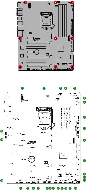
Place this side towards the rear of the chassis
1.2.3Motherboard layout
|
1-2 |
Chapter 1: Product introduction |

1.2.4Layout contents
|
Connectors/Jumpers/Slots/LED |
Page |
|
|
1. |
ATX power connectors (24-pin EATXPWR, 8-pin EATX12V) |
1-29 |
|
2. |
Intel® LGA1150 CPU socket |
1-4 |
|
3. |
CPU and chassis fan connectors (4-pin CPU_FAN, 4-pin CPU_OPT; |
1-28 |
|
CHA_FAN1, CHA_FAN2, CHA_FAN3, CHA_FAN4) |
||
|
4. |
DDR3 DIMM slots |
1-7 |
|
5. |
CPU Over Voltage jumper (3-pin CPU_OV) |
1-24 |
|
6. |
MemOK! button |
1-39 |
|
7. |
EZ XMP switch |
1-41 |
|
8. |
USB 3.0 connector (20-1 pin USB3_12) |
1-34 |
|
9. |
Intel® Z97 Serial ATA 6.0 Gb/s connector (7-pin SATA6G_1, SATA6G_2, |
1-27 |
|
SATA6G_34, SATA6G_56, SATA Express |
||
|
10. |
EPU switch |
1-38 |
|
11. |
TPU switch |
1-40 |
|
12. |
DirectKey connector (2-pin DRCT) |
1-31 |
|
13. |
System panel connector (20-8 pin PANEL) |
1-33 |
|
14. |
USB 2.0 connectors (10-1 pin USB910, USB1112, USB1314) |
1-32 |
|
15. |
T Sensor connector (2-pin T_SENSOR1) |
1-35 |
|
16. |
Clear RTC RAM (3-pin CLRTC) |
1-23 |
|
17. |
TPM connector (20-1 pin TPM) |
1-32 |
|
18. |
Power-on button |
1-41 |
|
19. |
Thunderbolt header (5-pin TB_HEADER) |
1-35 |
|
20. |
Serial port connector (10-1 pin COM) |
1-27 |
|
21. |
Front panel audio connector (10-1 pin AAFP) |
1-30 |
|
22. |
Digital audio connector (4-1 pin SPDIF_OUT) |
1-30 |
|
23. |
M.2 Socket 3 |
1-31 |

1.3Central Processing Unit (CPU)
The motherboard comes with a surface mount LGA1150 socket designed for the 4th Generation and New 4th Generation Intel® Core™ i7 / Intel® Core™ i5 / Intel® Core™ i3, Pentium®, and Celeron® processors.
Ensure that you install the correct CPU designed for LGA1150 socket only. DO NOT install a CPU designed for LGA1155 and LGA1156 sockets on the LGA1150 socket.
• Ensure that all power cables are unplugged before installing the CPU.
•Upon purchase of the motherboard, ensure that the PnP cap is on the socket and the socket contacts are not bent. Contact your retailer immediately if the PnP cap is missing, or if you see any damage to the PnP cap/socket contacts/motherboard components. ASUS will shoulder the cost of repair only if the damage is shipment/ transit-related.
•Keep the cap after installing the motherboard. ASUS will process Return Merchandise Authorization (RMA) requests only if the motherboard comes with the cap on the LGA1150 socket.
•The product warranty does not cover damage to the socket contacts resulting from incorrect CPU installation/removal, or misplacement/loss/incorrect removal of the PnP cap.
Unplug all power cables before installing the CPU.
|
1-4 |
Chapter 1: Product introduction |
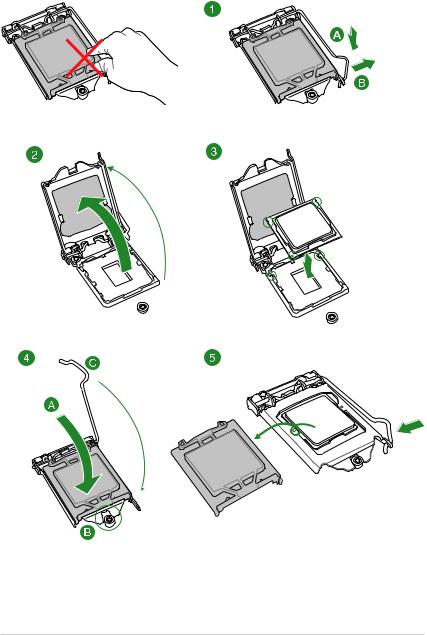
1.3.1Installing the CPU

1.3.2CPU heatsink and fan assembly installation
Apply the Thermal Interface Material to the CPU heatsink and CPU before you install the heatsink and fan, if necessary.
To install the CPU heatsink and fan assembly
|
1-6 |
Chapter 1: Product introduction |
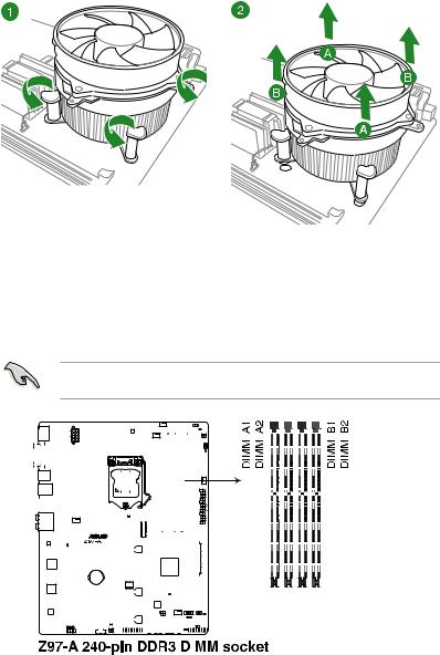
To uninstall the CPU heatsink and fan assembly
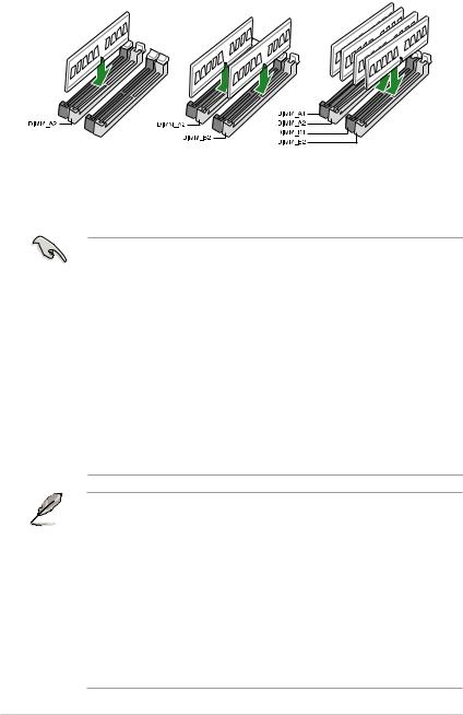
1.4System memory
1.4.1Overview
This motherboard comes with four Double Data Rate 3 (DDR3) Dual Inline Memory Module (DIMM) sockets. A DDR3 module is notched differently from a DDR or DDR2 module. DO NOT install a DDR or DDR2 memory module to the DDR3 slot.
According to Intel® CPU spec, DIMM voltage below 1.65 V is recommended to protect the CPU.
Recommended memory configurations
1.4.2Memory configurations
You may install 1 GB, 2 GB, 4 GB, and 8 GB unbuffered non-ECC DDR3 DIMMs into the DIMM sockets. You can refer to the recommended memory population below.
• You may install varying memory sizes in Channel A and Channel B. The system maps the total size of the lower-sized channel for the dual-channel configuration. Any excess memory from the higher-sized channel is then mapped for single-channel operation.
•Always install DIMMs with the same CAS latency. For optimal compatibility, we recommend that you install memory modules of the same version or date code (D/C) from the same vendor. Check with the retailer to get the correct memory modules.
•Due to the memory address limitation on 32-bit Windows® OS, when you install 4GB or more memory on the motherboard, the actual usable memory for the OS can be about 3GB or less. For effective use of memory, we recommend that you do any of the following:
—Use a maximum of 3 GB system memory if you are using a 32-bit Windows® OS.
—Install a 64-bit Windows® OS if you want to install 4GB or more on the motherboard.
•This motherboard does not support DIMMs made up of 512 Mb (64 MB) chips or less.
• The default memory operation frequency is dependent on its Serial Presence Detect (SPD), which is the standard way of accessing information from a memory module. Under the default state, some memory modules for overclocking may operate at a lower frequency than the vendor-marked value. To operate at the vendor-marked or at a higher frequency, refer to section 2.5 Ai Tweaker menu for manual memory frequency adjustment.
•Memory modules with memory frequency higher than 2133MHz and their corresponding timing or the loaded XMP profile is not the JEDEC memory standard. The stability and compatibility of the memory modules depend on the CPU’s capabilities and other installed devices.
•For system stability, use a more efficient memory cooling system to support a full memory load (4 DIMMs).
•Visit the ASUS website at: www.asus.com for the latest QVL.
|
1-8 |
Chapter 1: Product introduction |

Z97-A Motherboard Qualified Vendors Lists (QVL)
DDR3 3200 (O.C.) MHz capability
|
Vendors |
Part No. |
Size |
SS/DS |
Chip |
Chip |
Timing |
Voltage |
DIMM socket |
||
|
Brand |
NO. |
support (Optional) |
||||||||
|
1 |
2 |
4 |
||||||||
|
AVEXIR |
AVD3UH32001304G-4CI(XMP) |
16GB (4x4GB) |
SS |
— |
— |
13-15-15-35 |
1.65V |
• |
• |
• |
|
G.SKILL |
F3-3200C12Q-16GTXDG(XMP) |
16GB (4x4GB) |
SS |
— |
— |
12-15-15-35 |
1.65V |
• |
• |
• |
DDR3 3100 (O.C.) MHz capability
|
Vendors |
Part No. |
Size |
SS/DS |
Chip |
Chip |
Timing |
Voltage |
DIMM socket support |
||
|
Brand |
NO. |
(Optional) |
||||||||
|
1 |
2 |
4 |
||||||||
|
AVEXIR |
AVD3UH31001204G-4CI(XMP) |
16GB (4x4GB) |
SS |
— |
— |
12-14-14-35 |
1.65V |
• |
• |
• |
|
A-DATA |
AX3U3100W4G12-DMV(XMP) |
8GB (2x4GB) |
SS |
— |
— |
12-14-14-36 |
1.65V |
• |
• |
• |
DDR3 3000 (O.C.) MHz capability
|
Vendors |
Part No. |
Size |
SS/DS |
Chip |
Chip |
Timing |
Voltage |
DIMM socket |
||
|
Brand |
NO. |
support (Optional) |
||||||||
|
1 |
2 |
4 |
||||||||
|
AVEXIR |
AVD3UH30001204G-4BZ1(XMP) |
16GB (4x4GB) |
SS |
— |
— |
12-14-14-35 1.65V |
• |
• |
• |
|
|
G.SKILL |
F3-3000C12Q-16GTXDG(XMP) |
16GB (4x4GB) |
SS |
— |
— |
12-14-14-35 |
1.65V |
• |
• |
• |
|
G.SKILL |
F3-3000C12D-8GTXDG(XMP) |
8GB (2x4GB) |
SS |
12-14-14-35 |
1.65V |
• |
• |
• |
||
|
CORSAIR |
CMY8GX3M2A3000C12R(XMP) |
8GB (2x4GB) |
SS |
12-14-14-36 |
1.65V |
• |
• |
DDR3 2933 (O.C.) MHz capability
|
Vendors |
Part No. |
Size |
SS/DS Chip |
Chip |
Timing |
Voltage |
DIMM socket |
||
|
Brand |
NO. |
support |
|||||||
|
(Optional) |
|||||||||
|
1 |
2 |
4 |
|||||||
|
AVEXIR |
AVD3UH29331204G-4CI(XMP) |
16GB (4x4GB) |
SS |
12-14-14-35 |
1.65V |
• |
• |
• |
|
|
GEIL |
GPW38GB2933C12ADC(XMP) |
8GB (2x4GB) |
SS |
12-14-14-36 |
1.65V |
• |
• |
• |
|
|
APACER |
78.BAGHB.AFL0C(XMP) |
8GB (2x4GB) |
SS |
12-14-14-35 |
1.65V |
• |
• |
• |
|
|
A_DATA |
AX3U2933W4G12(XMP) |
16GB (4x4GB) |
SS |
12-14-14-36 |
1.65V |
• |
• |
• |
|
|
G.SKILL |
F3-2933C12D-8GTXDG(XMP) |
8GB (2x4GB) |
SS |
12-14-14-35 |
1.65V |
• |
• |
• |
|
|
G.SKILL |
F3-2933C12Q-16GTXDG(XMP) |
16GB (4x4GB) |
SS |
12-14-14-35 |
1.65V |
• |
• |
• |
|
|
CORSAIR |
CMY16GX3M4A2933C12R(XMP) |
16GB(4 x 4GB) |
SS |
12-14-14-36 |
1.65V |
• |
• |
• |

DDR3 2800 (O.C.) MHz capability
|
Vendors |
Part No. |
Size |
SS/DS |
Chip |
Chip |
Timing |
Voltage |
DIMM socket |
||
|
Brand |
NO. |
support |
||||||||
|
(Optional) |
||||||||||
|
1 |
2 |
4 |
||||||||
|
AVEXIR |
AVD3UH28001208G- |
32GB (4x8GB) |
DS |
— |
— |
12-14-14-35 |
1.65V |
• |
• |
• |
|
4BZ1(XMP) |
||||||||||
|
A_DATA |
AX3U2800W |
16GB (4x4GB) |
SS |
— |
— |
12-14-14-36 |
1.65V |
• |
• |
• |
|
4G12(XMP) |
||||||||||
|
A_DATA |
AX3U2800W |
32GB (4x8GB) |
DS |
— |
— |
12-14-14-36 |
1.65V |
• |
• |
|
|
8G12(XMP) |
||||||||||
|
G.SKILL |
F3-2800C12Q- |
32GB (4x8GB) |
DS |
— |
— |
12-13-13-35 |
1.65V |
• |
• |
• |
|
32GTXD(XMP) |
||||||||||
|
G.SKILL |
F3-2800C12Q- |
32GB (4x8GB) |
DS |
— |
— |
12-14-14-35 |
1.65V |
• |
• |
• |
|
32GTXDG(XMP) |
||||||||||
|
G.SKILL |
F3-2800C11Q- |
16GB (4x4GB) |
DS |
— |
— |
11-13-13-35 |
1.65V |
• |
• |
• |
|
16GTXD(XMP) |
||||||||||
|
G.SKILL |
F3-2800C11D- |
8GB (2x4GB) |
DS |
— |
— |
11-13-13-35 |
1.65V |
• |
• |
• |
|
8GTXD(XMP) |
||||||||||
|
G.SKILL |
F3-2800C11D- |
8GB (2x4GB) |
DS |
— |
— |
11-14-14-35 |
1.65V |
• |
• |
• |
|
8GTXDG(XMP) |
||||||||||
|
G.SKILL |
F3-2800C11Q- |
16GB (4x4GB) |
DS |
— |
— |
11-14-14-35 |
1.65V |
• |
• |
• |
|
16GTXDG(XMP) |
||||||||||
|
G.SKILL |
F3-2800C10D- |
8GB (2x4GB) |
DS |
— |
— |
10-12-12-35 |
1.65V |
• |
• |
• |
|
8GTXD(XMP) |
||||||||||
|
G.SKILL |
F3-2800C12Q- |
16GB (4x4GB) |
DS |
— |
— |
12-14-14-35 |
1.65V |
• |
• |
• |
|
16GTXDG(XMP) |
||||||||||
|
G.SKILL |
F3-2800C11D- |
16GB (2x8GB) |
DS |
— |
— |
11-14-14-35 |
1.65V |
• |
• |
• |
|
16GTXDG(XMP) |
||||||||||
|
G.SKILL |
F3-2800C11Q- |
32GB (4x8GB) |
DS |
— |
— |
11-14-14-35 |
1.65V |
• |
• |
• |
|
32GTXDG(XMP) |
||||||||||
|
G.SKILL |
F3-2800C11D- |
16GB (2x 8GB ) |
DS |
— |
— |
11-13-13-35 |
1.65V |
• |
• |
• |
|
16GTXD(XMP) |
||||||||||
|
G.SKILL |
F3-2800C11Q- |
32GB (4x8GB) |
DS |
— |
— |
11-13-13-35 |
1.65V |
• |
• |
• |
|
32GTXD(XMP) |
||||||||||
|
G.SKILL |
F3-2800C12D- |
16GB (2x8GB) |
DS |
— |
— |
12-14-14-35 |
1.65V |
• |
• |
• |
|
16GTXD(XMP) |
||||||||||
|
APACER |
78.BAGH5. |
8GB (2x4GB) |
DS |
— |
— |
12-14-14-35 |
1.65V |
• |
• |
|
|
AFD0C(XMP) |
||||||||||
|
APACER |
78.CAGH6. |
16GB (2x8GB) |
DS |
— |
— |
12-14-14-35 |
1.65V |
• |
• |
|
|
AFD0C(XMP) |
||||||||||
|
CORSAIR |
CMD16GX3M4A |
16GB (4x4GB) |
DS |
— |
— |
11-14-14-35 |
1.65V |
• |
• |
• |
|
2800C11(XMP) |
||||||||||
|
CORSAIR |
CMD16GX3M4A |
16GB (4x4GB) |
DS |
— |
— |
12-14-14-36 |
1.65V |
• |
• |
• |
|
2800C12(XMP) |
||||||||||
|
CORSAIR |
CMY16GX3M4A |
16GB (4x4GB) |
SS |
— |
— |
12-14-14-36 |
1.65V |
• |
• |
• |
|
2800C12R(XMP) |
||||||||||
|
KINGSTON |
KHX28C12T2K2/8X |
8GB (2x4GB) |
SS |
12-14-14-32 |
1.65V |
• |
• |
• |
||
|
Team |
TXD38G2800HC |
32GB (4x8GB) |
DS |
— |
— |
11-14-14-35 |
1.65V |
• |
• |
• |
|
12DBK(XMP) |
|
1-10 |
Chapter 1: Product introduction |
![]()
DDR3 2666 (O.C.) MHz capability
|
Vendors |
Part No. |
Size |
SS/DS |
Chip |
Chip |
Timing |
Voltage |
DIMM socket |
||
|
Brand |
NO. |
support |
||||||||
|
(Optional) |
||||||||||
|
1 |
2 |
4 |
||||||||
|
Apacer |
78.BAGFF.AFC0C(XMP) |
8GB (2x4GB) |
DS |
— |
— |
12-13-13-35 |
— |
• |
• |
• |
|
Apacer |
78.BAGFR.AFD0C(XMP) |
8GB (2x4GB) |
DS |
— |
— |
12-13-13-35 |
— |
• |
• |
• |
|
Apacer |
78.CAGFF.AFD0C(XMP) |
16GB (2x8GB) |
DS |
— |
— |
12-13-13-35 |
— |
• |
• |
• |
|
CORSAIR |
CMD16GX3M4A2666C11 |
16GB (4x4GB) |
DS |
— |
— |
11-13-13-35 |
1.65 |
• |
• |
• |
|
(Ver5.12)(XMP) |
||||||||||
|
G.SKILL |
F3-2666CL10Q- |
16GB (4x4GB) |
DS |
— |
— |
10-12-12-31 |
1.65 |
• |
• |
• |
|
16GBZHD(XMP) |
||||||||||
|
GEIL |
GOC332GB2666C11 |
32GB (4x8GB) |
DS |
— |
— |
11-13-13-32 |
1.65 |
• |
• |
• |
|
QC(XMP) |
||||||||||
|
KINGSTON |
KHX26C11T2K2/8X(XMP) |
8GB (2x4GB) |
SS |
— |
— |
2666-11-13-13-32 |
1.65 |
• |
• |
DDR3 2500 (O.C.)* MHz capability
|
Vendors |
Part No. |
Size |
SS/DS |
Chip |
Chip |
Timing |
Voltage |
DIMM socket |
||
|
Brand |
NO. |
support (Optional) |
||||||||
|
1 |
2 |
4 |
||||||||
|
G.SKILL |
F3-20000CL10Q-16GBZHD(XMP) |
16GB (4x4GB) |
DS |
— |
— |
10-11-11-31 |
1.65 |
• |
• |
• |
*The above QVL is for the DDR3 2500 MHz memory module. Due to CPU behavior, DDR3 2500 MHz memory module will run at DDR3 2400 MHz frequency.
DDR3 2400 (O.C.) MHz capability
|
Vendors |
Part No. |
Size |
SS/DS |
Chip |
Chip |
Timing |
Voltage |
DIMM socket |
||
|
Brand |
NO. |
support |
||||||||
|
(Optional) |
||||||||||
|
1 |
2 |
4 |
||||||||
|
A-DATA |
AX3U2400W4G11-DMV(XMP) |
8GB (2x4GB) |
SS |
— |
— |
11-13-13-35 |
1.65 |
• |
• |
• |
|
A-DATA |
AX3U2400W8G11-DMV(XMP) |
16GB (2x8GB) |
DS |
— |
— |
11-13-13-35 |
1.65 |
• |
• |
• |
|
Apacer |
78.BAGFL.AFD0C(XMP) |
8GB (2x4GB) |
DS |
— |
— |
11-12-12-30 |
— |
• |
• |
• |
|
Apacer |
783BAGF3.AFD0C(XMP) |
8GB (2x4GB) |
DS |
— |
— |
11-11-11-30 |
— |
• |
• |
• |
|
CORSAIR |
CMD16GX3M2A2400C10 |
16GB (2x8GB) |
DS |
— |
— |
10-12-12-31 |
1.65 |
• |
• |
• |
|
(Ver4.21)(XMP) |
||||||||||
|
CORSAIR |
CMD32GX3M4A2400C10 |
32GB (4x8GB) |
DS |
— |
— |
10-12-12-31 |
1.65 |
• |
• |
|
|
(Ver5.29)(XMP) |
||||||||||
|
CORSAIR |
CMY16GX3M2A 2400C10A |
16GB (8x2GB) |
DS |
— |
— |
10-12-12-31 |
1.65 |
• |
• |
• |
|
(Ver4.21)(XMP) |
||||||||||
|
CORSAIR |
CMY16GX3M2A 2400C10R |
16GB (2x8GB) |
DS |
— |
— |
10-12-12-31 |
1.65 |
• |
• |
• |
|
(Ver4.21)(XMP) |
||||||||||
|
CORSAIR |
CMZ16GX3M2A2400C10 |
16GB (2x8GB) |
DS |
— |
— |
10-12-12-31 |
1.65 |
• |
• |
• |
|
(Ver4.21) |
||||||||||
|
G.SKILL |
F3-19200CL10Q2- |
64GB (8x8GB) |
DS |
— |
— |
10-12-12-31 |
1.65 |
• |
• |
• |
|
64GBZHD(XMP) |
||||||||||
|
G.SKILL |
F3-19200CL10Q- |
32GB (4x8GB) |
DS |
— |
— |
10-12-12-31 |
1.65 |
• |
• |
|
|
32GBZHD(XMP) |
||||||||||
|
G.SKILL |
F3-19200CL11Q- |
16GB (4x4GB) |
DS |
— |
— |
11-11-11-31 |
1.65 |
• |
• |
• |
|
16GBZHD(XMP) |
||||||||||
|
G.SKILL |
F3-19200CL9D-4GBPIS(XMP) |
4G (2x2GB) |
DS |
— |
— |
9-11-9-28 |
1.65 |
• |
• |
(continued on the next page)

DDR3 2400 (O.C.) MHz capability
|
Vendors |
Part No. |
Size |
SS/DS |
Chip |
Chip |
Timing |
Voltage |
DIMM socket |
||
|
Brand |
NO. |
support |
||||||||
|
(Optional) |
||||||||||
|
1 |
2 |
4 |
||||||||
|
G.SKILL |
F3-19200CL9Q- |
16GB (4x4GB) |
DS |
— |
— |
9-11-11-31 |
1.65 |
• |
• |
• |
|
16GBZMD(XMP) |
||||||||||
|
G.SKILL |
F3-2400C11Q-32GXM(XMP) |
32GB (4x8GB) |
DS |
— |
— |
11-13-13-31 |
1.65 |
• |
• |
• |
|
GEIL |
GOC316GB24 |
16GB (4x4GB) |
DS |
— |
— |
10-11-11-30 |
1.65 |
• |
• |
• |
|
00C10QC(XMP) |
||||||||||
|
GEIL |
GOC316GB24 |
16GB (4x4GB) |
DS |
— |
— |
11-11-11-30 |
1.65 |
• |
• |
• |
|
00C11QC(XMP) |
||||||||||
|
Kingston |
KHX2400C11D |
8GB (4x2GB) |
SS |
— |
— |
11-13-11-30 |
1.65 |
• |
• |
• |
|
3K4/8GX(XMP) |
||||||||||
|
KINGSTON |
KHX24C11K4/16X(XMP) |
16GB (4x4GB) |
DS |
— |
— |
11-13-13-30 |
1.65 |
• |
• |
• |
|
KINGSTON |
KHX24C11T2K2/8X(XMP) |
8GB (2x4GB) |
DS |
— |
— |
— |
1.65 |
• |
• |
• |
|
KINGSTON |
KHX24C11T3K2/16X(XMP) |
16GB (2x8GB) |
DS |
— |
— |
2400-11-13-13-32 |
1.65 |
• |
• |
|
|
KINGSTON |
KHX24C11T3K4(XMP) |
16GB (4x4GB) |
DS |
— |
— |
2400-11-13-13-30 |
1.65 |
• |
• |
• |
|
KINGSTON |
KHX24C11T3K4/32X(XMP) |
32GB (4x8GB) |
DS |
— |
— |
9-9-9-24 |
1.65 |
• |
• |
• |
|
Mushkin |
997122R(XMP) |
16GB (2x8GB) |
DS |
— |
— |
2400-10-12-12-28 |
1.65 |
• |
• |
• |
|
Silicon |
SP004GXLYU240NSA(XMP) |
4GB |
SS |
— |
— |
2400-11-13-13-32 |
— |
• |
• |
• |
|
Power |
||||||||||
|
Transcend |
TX2400KLN-8GK(XMP) |
8GB (2x4GB) |
DS |
— |
— |
2400-11-12-11-29 |
1.6 |
• |
• |
• |
DDR3 2200 (O.C.) MHz capability
|
Vendors |
Part No. |
Size |
SS/DS |
Chip |
Chip |
Timing |
Voltage |
DIMM socket |
||
|
Brand |
NO. |
support (Optional) |
||||||||
|
1 |
2 |
4 |
||||||||
|
G.SKILL |
F3-17600CL7D-4GBFLS(XMP) |
4G (2x2GB) |
DS |
— |
— |
7-10-10-28 |
1.65 |
• |
• |
|
|
GEIL |
GET34GB2200C9DC(XMP) |
4GB (2x2GB) |
DS |
— |
— |
9-10-9-28 |
1.65 |
• |
• |
• |
|
GEIL |
GET38GB2200C9ADC(XMP) |
8GB (2x4GB) |
DS |
— |
— |
9-11-9-28 |
1.65 |
• |
• |
DDR3 2133 (O.C.) MHz capability
|
Vendors |
Part No. |
Size |
SS/DS |
Chip |
Chip |
Timing |
Voltage |
DIMM socket |
||
|
Brand |
NO. |
support |
||||||||
|
(Optional) |
||||||||||
|
1 |
2 |
4 |
||||||||
|
A-DATA |
AX3U2133W4G10-DR(XMP) |
8GB (2x4GB) |
SS |
— |
— |
10-11-11-30 |
1.65 |
• |
• |
• |
|
A-DATA |
AX3U2133W8G10-DR(XMP) |
16GB (2x8GB) |
DS |
— |
— |
10-11-11-30 |
1.65 |
• |
• |
• |
|
Apacer |
78.BAGE4.AFD0C(XMP) |
8GB (2x4GB) |
DS |
— |
— |
9-9-9-24 |
— |
• |
• |
• |
|
Apacer |
AHU04GFB33CAQ3R(XMP) |
4GB |
DS |
— |
— |
11-13-13-31 |
— |
• |
• |
• |
|
CORSAIR |
CMD16GX3M2A2133C9 (Ver4.21) |
16GB (2x8GB) |
DS |
— |
— |
9-11-11-31 |
1.65 |
• |
• |
• |
|
(XMP) |
||||||||||
|
CORSAIR |
CMD32GX3M4A2133C9 (Ver4.21) |
32GB (4x8GB) |
DS |
— |
— |
9-11-11-31 |
1.65 |
• |
• |
• |
|
(XMP) |
||||||||||
|
CORSAIR |
CMD8GX3M2A2133C9 (Ver1.5) |
8GB (2x4GB) |
DS |
— |
— |
9-11-10-27 |
1.5 |
• |
• |
|
|
(XMP) |
||||||||||
|
CORSAIR |
CMD8GX3M2B2133C9 (Ver5.12) |
8GB (2x4GB) |
DS |
— |
— |
9-11-11-31 |
1.65 |
• |
• |
• |
|
(XMP) |
(continued on the next page)
|
1-12 |
Chapter 1: Product introduction |

DDR3 2133 (O.C.) MHz capability
|
Vendors |
Part No. |
Size |
SS/DS |
Chip |
Chip |
Timing |
Voltage |
DIMM socket |
||
|
Brand |
NO. |
support |
||||||||
|
(Optional) |
||||||||||
|
1 |
2 |
4 |
||||||||
|
CORSAIR |
CMY8GX3M2A2133C11R |
8GB (2x4GB) |
DS |
— |
— |
11-11-11-27 |
1.5 |
• |
• |
• |
|
(Ver4.21)(XMP) |
||||||||||
|
CORSAIR |
CMZ8GX3M2A2133C11R |
8GB (2x4GB) |
DS |
— |
— |
11-11-11-27 |
1.5 |
• |
• |
• |
|
(Ver4.21)(XMP) |
||||||||||
|
G.SKILL |
F3-17000CL11Q2- |
64GB (8x8GB) |
DS |
— |
— |
11-11-11-30 |
1.5 |
• |
• |
• |
|
64GBZLD(XMP) |
||||||||||
|
G.SKILL |
F3-17000CL9Q- |
16GB (4x4GB) |
DS |
— |
— |
9-11-10-28 |
1.65 |
• |
• |
• |
|
16GBZH(XMP) |
||||||||||
|
G.SKILL |
F3-2133C10Q-32GSR(XMP) |
32GB (4x8GB) |
DS |
— |
— |
10-12-12-31 |
1.5 |
• |
• |
• |
|
G.SKILL |
F3-2133C11Q-32GZL(XMP) |
32GB (4x8GB) |
DS |
— |
— |
11-11-11-31 |
1.5 |
• |
• |
• |
|
KINGSTON |
KHX2133C11D3 |
16GB (4x4GB) |
DS |
— |
— |
11-12-11-30 |
1.65 |
• |
• |
• |
|
K4/16GX(XMP) |
||||||||||
|
KINGSTON |
KHX21C11T3FK |
64GB (8x8GB) |
DS |
— |
— |
9-9-9-24 |
1.5 |
• |
• |
• |
|
8/64X(XMP) |
||||||||||
|
Silicon |
SP004GXLYU213NSA(XMP) |
4GB |
SS |
— |
— |
2133-11-12- |
— |
• |
• |
• |
|
Power |
11-30 |
|||||||||
|
Silicon |
SP008GXLYU213NSA(XMP) |
8GB |
DS |
— |
— |
2133-11-12- |
— |
• |
• |
• |
|
Power |
11-30 |
|||||||||
|
Transcend |
TX2133KLH-16GK(XMP) |
16GB (2x8GB) |
DS |
— |
— |
2133-10-11- |
1.6 |
• |
• |
• |
|
10-27 |
||||||||||
|
Transcend |
TX2133KLN-8GK(XMP) |
8GB (2x4GB) |
DS |
— |
— |
2133-10-11- |
1.6 |
• |
• |
• |
|
10-27 |
DDR3 2000 (O.C.) MHz capability
|
Vendors |
Part No. |
Size |
SS/DS |
Chip |
Chip NO. |
Timing |
Voltage |
DIMM socket |
||
|
Brand |
support |
|||||||||
|
(Optional) |
||||||||||
|
1 |
2 |
4 |
||||||||
|
AEXEA |
AXA3ES4GK2000LG28V(XMP) |
4GB (2x2GB) |
DS |
— |
— |
— |
1.65 |
• |
• |
• |
|
Asint |
SLA302G08-ML2HB(XMP) |
4GB |
DS |
Hynix |
H5TQ2G83 |
9-9-9-27 |
— |
• |
• |
• |
|
BFRH9C |
||||||||||
|
GEIL |
GUP34GB2000C9DC(XMP) |
4GB (2x2GB) |
DS |
— |
— |
9-9-9-28 |
1.65 |
• |
• |
• |
DDR3 1866 (O.C.) MHz capability
|
Vendors |
Part No. |
Size |
SS/DS |
Chip |
Chip |
Timing |
Voltage |
DIMM socket support |
||
|
Brand |
NO. |
(Optional) |
||||||||
|
1 |
2 |
4 |
||||||||
|
CORSAIR |
CMD16GX3M2A1866C9 |
16GB (2x8GB) |
DS |
— |
— |
1866 9-9-9-27 |
1.5 |
• |
• |
|
|
(Ver5.29)(XMP) |
||||||||||
|
CORSAIR |
CMD16GX3M4A1866C9 |
16GB (4x4GB) |
DS |
— |
— |
9-10-9-27 |
1.5 |
• |
• |
• |
|
(Ver4.13)(XMP) |
||||||||||
|
CORSAIR |
CMD16GX3M4A1866C9 |
16GB (4x4GB) |
DS |
— |
— |
9-10-9-27 |
1.5 |
• |
• |
• |
|
(Ver8.16)(XMP) |
||||||||||
|
CORSAIR |
CMD32GX3M4A1866C9 |
32GB (4x8GB) |
DS |
— |
— |
9-10-9-27 |
1.5 |
• |
• |
• |
|
(Ver3.24)(XMP) |
||||||||||
|
CORSAIR |
CMD8GX3M2A1866C9 |
8GB (2x4GB) |
DS |
— |
— |
— |
1.5 |
• |
• |
• |
|
(Ver4.13)(XMP) |
||||||||||
|
CORSAIR |
CMD8GX3M2A1866C9 |
8GB (2x4GB) |
DS |
— |
— |
9-10-9-27 |
1.5 |
• |
• |
|
|
(Ver5.12)(XMP) |
||||||||||
|
CORSAIR |
CMD8GX3M2A1866C9 |
8GB (2x4GB) |
DS |
— |
— |
9-10-9-27 |
1.5 |
• |
• |
|
|
(Ver8.16)(XMP) |
(continued on the next page)

DDR3 1866 (O.C.) MHz capability
|
Vendors |
Part No. |
Size |
SS/DS |
Chip |
Chip |
Timing |
Voltage |
DIMM socket |
||
|
Brand |
NO. |
support (Optional) |
||||||||
|
1 |
2 |
4 |
||||||||
|
CORSAIR |
CMT32GX3M4X1866C9(Ver3.23) |
32GB |
DS |
— |
— |
9-10-9-27 |
1.5 |
• |
• |
• |
|
(XMP) |
(4x8GB) |
|||||||||
|
CORSAIR |
CMY16GX3M2A1866C9 (Ver |
16GB |
DS |
— |
— |
9-10-9-27 |
1.5 |
• |
• |
• |
|
4.21)(XMP) |
(2x8GB) |
|||||||||
|
CORSAIR |
CMY8GX3M2A1866C9 (Ver3.24) |
8GB |
DS |
— |
— |
9-10-9-27 |
1.5 |
• |
• |
• |
|
(XMP) |
(2x4GB) |
|||||||||
|
CORSAIR |
CMZ16GX3M2A1866C10 |
16GB |
DS |
— |
— |
10-11-10-30 |
1.5 |
• |
• |
• |
|
(Ver5.29)(XMP) |
(2x8GB) |
|||||||||
|
CORSAIR |
CMZ16GX3M2A1866C9(XMP) |
16GB |
DS |
— |
— |
1866-9-10-9-27 |
1.5 |
• |
• |
• |
|
(2x8GB) |
||||||||||
|
CORSAIR |
CMZ32GX3M4X1866C10 |
32GB |
DS |
— |
— |
10-11-10-27 |
1.5 |
• |
• |
• |
|
(Ver3.23)(XMP) |
(4x8GB) |
|||||||||
|
CORSAIR |
CMZ32GX3M4X1866C10(Ver3.23) |
32GB |
DS |
— |
— |
10-11-10-27 |
1.5 |
• |
• |
• |
|
(XMP) |
(4x8GB) |
|||||||||
|
CORSAIR |
CMZ8GX3M2A1866C9 (Ver8.16) |
8GB |
DS |
— |
— |
9-10-9-27 |
1.5 |
• |
• |
• |
|
(XMP) |
(2x4GB) |
|||||||||
|
CORSAIR |
CMZ8GX3M2A1866C9(XMP) |
8GB |
DS |
— |
— |
9-10-9-27 |
1.5 |
• |
• |
|
|
(2x4GB) |
||||||||||
|
CORSAIR |
CMZ8GX3M2A1866C9G |
8GB |
DS |
— |
— |
1866 9-10-9-27 |
1.5 |
• |
• |
• |
|
(Ver5.12)(XMP) |
(2x4GB) |
|||||||||
|
Cricial |
BLE8G3D1869DE1T |
16GB |
DS |
— |
— |
1866-9-9-9-27 |
1.5 |
• |
• |
• |
|
X0.16FED(XMP) |
(2x8GB) |
|||||||||
|
Crucial |
BLE4G3D1869DE1X |
4GB |
DS |
— |
— |
9-9-9-27 |
1.5 |
• |
• |
• |
|
T0.16FMD(XMP) |
||||||||||
|
G.SKILL |
F3-14900CL10Q-32GBZL(XMP) |
32GB |
DS |
— |
— |
10-11-10-30 |
1.5 |
• |
• |
• |
|
(4x8GB) |
||||||||||
|
G.SKILL |
F3-14900CL9D-8GBSR(XMP) |
8GB |
DS |
— |
— |
9-10-9-28 |
1.5 |
• |
• |
• |
|
(2x4GB) |
||||||||||
|
G.SKILL |
F3-14900CL9Q-16GBXL(XMP) |
16GB |
DS |
— |
— |
9-10-9-28 |
1.5 |
• |
• |
• |
|
(4x4GB) |
||||||||||
|
G.SKILL |
F3-14900CL9Q-16GBZL(XMP) |
16GB |
DS |
— |
— |
9-10-9-28 |
1.5 |
• |
• |
• |
|
(4x4GB) |
||||||||||
|
G.SKILL |
F3-14900CL9Q-16GBZL(XMP) |
16GB |
DS |
— |
— |
9-10-9-28 |
1.5 |
• |
• |
• |
|
(4x4GB) |
||||||||||
|
G.SKILL |
F3-1866C10Q2-64GZM(XMP) |
64GB |
DS |
— |
— |
10-11-10-30 |
1.5 |
• |
• |
• |
|
(2x8GB) |
||||||||||
|
G.SKILL |
F3-1866C10Q2-64GZM(XMP) |
64GB |
DS |
— |
— |
10-11-10-30 |
1.5 |
• |
• |
• |
|
(2x8GB) |
||||||||||
|
G.SKILL |
F3-1866C9Q-32GXM(XMP) |
32GB |
DS |
— |
— |
9-10-9-28 |
1.5 |
• |
• |
• |
|
(4x8GB) |
||||||||||
|
GEIL |
GEEL316GB1866C9DC(XMP) |
16GB |
DS |
— |
— |
1866-9-10-9-28 |
1.65 |
• |
• |
• |
|
(2x8GB) |
||||||||||
|
KINGSTON |
KHX1866C9D3K2/8GX(XMP) |
8GB |
DS |
— |
— |
— |
1.65 |
• |
• |
• |
|
(2x4GB) |
||||||||||
|
Silicon |
SP004GXLYU186NSA(XMP) |
4GB |
SS |
— |
— |
1866-9-11-9-27 |
— |
• |
• |
• |
|
Power |
||||||||||
|
Silicon |
SP008GXLYU186NSA(XMP) |
8GB |
DS |
— |
— |
1866-9-11-9-27 |
— |
• |
• |
• |
|
Power |
|
1-14 |
Chapter 1: Product introduction |

DDR3 1600 MHz capability
|
Vendors |
Part No. |
Size |
SS/DS |
Chip |
Chip NO. |
Timing |
Voltage |
DIMM socket |
||
|
Brand |
support (Optional) |
|||||||||
|
1 |
2 |
4 |
||||||||
|
A-DATA |
AD3U1600W4G11 |
4GB |
SS |
A-DATA |
3WCD-1211A |
11-11-11-28 |
— |
• |
• |
• |
|
A-DATA |
AD3U1600W8G11 |
8GB |
DS |
A-DATA |
3WCD-1211A |
11-11-11-28 |
— |
• |
• |
• |
|
A-DATA |
ADDU1600W |
4GB |
SS |
A-DATA |
DWND-1211A |
9-9-9-24 |
— |
• |
• |
• |
|
4G11-B |
||||||||||
|
A-DATA |
ADDU1600W |
8GB |
DS |
ELPIDA |
J4208EBBG-GN-F |
9-9-9-24 |
— |
• |
• |
• |
|
8G11-B |
||||||||||
|
A-DATA |
AX3U1600W4G9- |
8GB |
SS |
— |
— |
9-9-9-24 |
1.5 |
• |
• |
• |
|
DB(XMP) |
(2x4GB) |
|||||||||
|
A-DATA |
AX3U1600W8G9- |
16GB |
DS |
— |
— |
9-9-9-24 |
1.5 |
• |
• |
• |
|
DB(XMP) |
(2x8GB) |
|||||||||
|
AMD |
AE32G1609U1-U |
2GB |
SS |
AMD |
23EY4587MB6H |
— |
1.5 |
• |
• |
• |
|
AMD |
AE34G1609U2-U |
4GB |
DS |
AMD |
23EY4587MB6H |
— |
1.5 |
• |
• |
• |
|
AMD |
AP38G1608U |
8GB |
DS |
— |
— |
9-9-9-28 |
1.65 |
• |
• |
• |
|
2K(XMP) |
(2x4GB) |
|||||||||
|
Apacer |
78.B1GE3.9L10C |
4GB |
DS |
Apacer |
AM5D5908DEQSCK |
— |
1.65 |
• |
• |
• |
|
Apacer |
78.B1GET.9K00C |
4GB |
SS |
Apacer |
AM5D6008BQQSCK |
11-11-11-28 |
— |
• |
• |
• |
|
Apacer |
78.C1GET.9K10C |
8GB |
DS |
Apacer |
AM5D6008BQQSCK |
11-11-11-31 |
— |
• |
• |
• |
|
Apacer |
AHU04GFA60C9 |
4GB |
DS |
— |
— |
11-11-11-28 |
— |
• |
• |
• |
|
Q3R(XMP) |
||||||||||
|
Apacer |
AHU08GFA60CB |
8GB |
DS |
— |
— |
9-9-9-24 |
— |
• |
• |
|
|
T3R(XMP) |
||||||||||
|
Asint |
SLA302G08-EGG |
4GB |
DS |
Asint |
302G08-GG1C |
9-9-9-27 |
— |
• |
• |
• |
|
1C(XMP) |
||||||||||
|
Asint |
SLA302G08-EGJ |
4GB |
DS |
Asint |
302G08-GJ1C |
9-9-9-27 |
— |
• |
• |
• |
|
1C(XMP) |
||||||||||
|
Asint |
SLA302G08- |
4GB |
DS |
ASint |
302G08-GN1C |
— |
— |
• |
• |
• |
|
EGN 1C |
||||||||||
|
Asint |
SLA304G08- |
4GB |
SS |
Asint |
304G08-GN1B |
9-11-11-28 |
— |
• |
• |
• |
|
ENG1B |
||||||||||
|
Asint |
SLB304G08-EGJ |
8GB |
DS |
— |
— |
9-9-9-27 |
— |
• |
• |
• |
|
1B(XMP) |
||||||||||
|
Asint |
SLB304G08-EG |
8GB |
DS |
ASint |
304G08-GN1B |
— |
— |
• |
• |
• |
|
N1B |
||||||||||
|
Asint |
SLZ302G08-EG |
2GB |
SS |
ASint |
302G08-GN1C |
— |
— |
• |
• |
• |
|
N1C |
||||||||||
|
AVEXIR |
AVD3U16000904G |
8GB |
DS |
— |
— |
11-11-11-28 |
1.5 |
• |
• |
• |
|
-2CW(XMP) |
(2x4GB) |
|||||||||
|
CORSAIR |
CMD16GX3M2A16 |
16GB |
DS |
— |
— |
9-9-9-24 |
1.5 |
• |
• |
|
|
00C9 (Ver8.21) |
(2x8GB) |
|||||||||
|
(XMP) |
||||||||||
|
CORSAIR |
CMD8GX3M2A160 |
8GB |
DS |
— |
— |
1600 8-8- |
1.5 |
• |
• |
• |
|
0C8 (Ver5.12) |
(2x4GB) |
8-24 |
||||||||
|
(XMP) |
||||||||||
|
CORSAIR |
CMD8GX3M2A160 |
8GB |
DS |
— |
— |
9-9-9-24 |
1.5 |
• |
• |
• |
|
0C9 (Ver2.12) |
(2x4GB) |
|||||||||
|
(XMP) |
||||||||||
|
CORSAIR |
CML16GX3M2A1 |
16GB |
DS |
— |
— |
10-10-10-27 |
1.5 |
• |
• |
• |
|
600C10 (Ver2.21) |
(2x8GB) |
|||||||||
|
(XMP) |
||||||||||
|
CORSAIR |
CML8GX3M2A16 |
8GB |
DS |
— |
— |
9-9-9- 24 |
1.5 |
• |
• |
• |
|
00C9 (Ver7.12) |
(2x4GB) |
|||||||||
|
(XMP) |
||||||||||
|
CORSAIR |
CMV8GX3M1A1 |
8GB |
DS |
— |
— |
11-11-11-30 |
— |
• |
• |
• |
|
600C11 |
||||||||||
|
CORSAIR |
CMX8GX3M2 |
8GB |
SS |
— |
— |
9-9-9-24 |
1.65 |
• |
• |
• |
|
A1600C9 (Ver3.19) |
(2x4GB) |
|||||||||
|
(XMP) |
(continued on the next page)

DDR3 1600 MHz capability
|
Vendors |
Part No. |
Size |
SS/DS |
Chip |
Chip NO. |
Timing |
Voltage |
DIMM socket |
||
|
Brand |
support (Optional) |
|||||||||
|
1 |
2 |
4 |
||||||||
|
CORSAIR |
CMZ16GX3M2A1 |
16GB |
DS |
— |
— |
10-10- |
1.5 |
• |
• |
• |
|
600C10 (Ver.3.24) |
(2x8GB) |
10-27 |
||||||||
|
(XMP ) |
||||||||||
|
CORSAIR |
CMZ16GX3M |
16GB |
DS |
— |
— |
9-9-9-24 |
1.5 |
• |
• |
• |
|
4A1600C9(XMP) |
(4x4GB) |
|||||||||
|
CORSAIR |
CMZ16GX3M4X1600C9 |
16GB |
DS |
— |
— |
1600-9-9- |
1.5 |
• |
• |
• |
|
(Ver8.16)(XMP) |
(4x4GB) |
9-24 |
||||||||
|
CORSAIR |
CMZ32GX3M |
32GB |
DS |
— |
— |
10-10- |
1.5 |
• |
• |
• |
|
4X1600C10 (Ver2.2) |
(4x8GB) |
10-27 |
||||||||
|
(XMP) |
||||||||||
|
CORSAIR |
CMZ4GX3M1A1600C9 |
4GB |
DS |
— |
— |
9-9-9-24 |
1.5 |
• |
• |
|
|
(Ver8.16)(XMP) |
(1x4GB) |
|||||||||
|
CORSAIR |
CMZ8GX3M1A1600C10 |
8GB |
DS |
— |
— |
10-10- |
1.5 |
• |
• |
|
|
(Ver3.23)(XMP) |
(1x8GB) |
10-27 |
||||||||
|
CORSAIR |
CMZ8GX3M1A1600C10 |
8GB |
DS |
— |
— |
10-10- |
1.5 |
• |
• |
|
|
(Ver8.21)(XMP) |
(1x8GB) |
10-27 |
||||||||
|
CORSAIR |
CMZ8GX3M2A |
8GB |
DS |
— |
— |
8-8-8-24 |
1.5 |
• |
• |
• |
|
1600C8(XMP) |
(2x4GB) |
|||||||||
|
Crucial |
BLS4G3D1609 |
4GB |
DS |
— |
— |
1600-9-9- |
1.5 |
• |
• |
• |
|
DS1S00.16FMR(XMP) |
9-24 |
|||||||||
|
Crucial |
BLT4G3D1608 |
4GB |
DS |
— |
— |
8-8-8-24 |
1.5 |
• |
• |
• |
|
DT1TX0.16FM(XMP) |
||||||||||
|
Elixir |
M2X2G64CB88G7N- |
2GB |
SS |
Elixir |
N2CB G80GN- |
9-9-9-28 |
— |
• |
• |
• |
|
DG(XMP) |
DG |
|||||||||
|
Elixir |
M2X4G64CB8HG5N- |
4GB |
DS |
Elixir |
N2CB |
9-9-9-28 |
— |
• |
• |
• |
|
DG(XMP) |
2G80GN-DG |
|||||||||
|
G.SKILL |
F3-12800CL9D- |
8GB |
DS |
— |
— |
9-9-9-24 |
1.25 |
• |
• |
• |
|
8GBSR2(XMP) |
(2x4GB) |
|||||||||
|
G.SKILL |
F3-12800CL9Q- |
16GB |
DS |
— |
— |
9-9-9-24 |
1.5 |
• |
• |
• |
|
16GBXL(XMP) |
(4x4GB) |
|||||||||
|
G.Skill |
F3-12800CL9Q- |
16GB |
DS |
— |
— |
9-9-9-24 |
1.5 |
• |
• |
• |
|
16GBZL(XMP) |
(4x4GB) |
|||||||||
|
G.SKILL |
F3-1600C9Q- |
32GB |
DS |
— |
— |
— |
1.5 |
• |
• |
• |
|
32GXM(XMP) |
(4x8GB) |
|||||||||
|
GEIL |
GUP34GB1600 |
4GB |
DS |
— |
— |
7-7-7-24 |
1.6 |
• |
• |
• |
|
C7DC(XMP) |
(2x2GB) |
|||||||||
|
KINGMAX |
FLGE85F- |
2GB |
SS |
KINGMAX |
N/A |
9-9-9-28 |
— |
• |
• |
• |
|
C8KL9A(XMP) |
||||||||||
|
KINGMAX |
FLGF65F- |
4GB |
DS |
KINGMAX |
N/A |
9-9-9-28 |
— |
• |
• |
• |
|
C8KL9A(XMP) |
||||||||||
|
KINGSTON |
KHX16009CD3 |
8GB |
DS |
— |
— |
9-9-9-27 |
1.65 |
• |
• |
• |
|
K2/8GX(XMP) |
(2x4GB) |
|||||||||
|
KINGSTON |
KHX1600C9D3 |
4GB |
SS |
— |
— |
9-9-9-27 |
1.65 |
• |
• |
• |
|
B1/4G(XMP) |
||||||||||
|
KINGSTON |
KHX1600C9D3 |
12GB |
DS |
— |
— |
9 |
1.65 |
• |
• |
|
|
K3/12GX(XMP) |
(3x4GB) |
|||||||||
|
KINGSTON |
KHX1600C9D3 |
6GB |
DS |
— |
— |
9 |
1.65 |
• |
• |
• |
|
K3/6GX(XMP) |
(3x2GB) |
|||||||||
|
KINGSTON |
KHX1600C9D3 |
6GB |
DS |
— |
— |
9 |
1.65 |
• |
• |
• |
|
K3/6GX(XMP) |
(3x2GB) |
|||||||||
|
KINGSTON |
KHX1600C9D3K |
16GB |
DS |
— |
— |
9-9-9-24 |
1.65 |
• |
• |
• |
|
4/16GX(XMP) |
(4x4GB) |
|||||||||
|
KINGSTON |
KHX1600C9D3K |
24GB |
DS |
— |
— |
9 |
1.65 |
• |
• |
• |
|
6/24GX(XMP) |
(6x4GB) |
|||||||||
|
KINGSTON |
KHX1600C9D3L |
8GB |
DS |
— |
— |
9-9-9-24 |
1.35 |
• |
• |
• |
|
K2/8GX(XMP) |
(2x4GB) |
|||||||||
|
KINGSTON |
KHX1600C9D3P1K2/8G |
8GB |
DS |
— |
— |
9 |
1.5 |
• |
• |
• |
|
(2x4GB) |
(continued on the next page)
|
1-16 |
Chapter 1: Product introduction |

DDR3 1600 MHz capability
|
Vendors |
Part No. |
Size |
SS/DS |
Chip |
Chip NO. |
Timing |
Voltage |
DIMM socket |
||
|
Brand |
support |
|||||||||
|
(Optional) |
||||||||||
|
1 |
2 |
4 |
||||||||
|
KINGSTON |
KHX16C10 |
16GB |
DS |
— |
— |
— |
1.5 |
• |
• |
• |
|
B1K2/16X(XMP) |
(2x8GB) |
|||||||||
|
KINGSTON |
KHX16C9K2/16 |
16GB |
DS |
— |
— |
1333-9-9-9-24 |
1.5 |
• |
• |
• |
|
(2x8GB) |
||||||||||
|
KINGSTON |
KHX16C9P1K2/16 |
16GB |
DS |
— |
— |
— |
1.5 |
• |
• |
• |
|
(2x8GB) |
||||||||||
|
KINGSTON |
KVR16N11/4 |
4GB |
DS |
KINGSTON |
D2568JP |
11-11-11-28-1 |
— |
• |
• |
• |
|
UCPGGBU |
||||||||||
|
KINGSTON |
KVR16N11/4 |
4G |
DS |
Hynix |
H5TQ2G8 |
— |
1.5 |
• |
• |
• |
|
3CFRPBC |
||||||||||
|
Micron |
MT16JTF1G64AZ- |
8GB |
DS |
Micron |
D9QBJ |
— |
— |
• |
• |
• |
|
1G6E1 |
||||||||||
|
Micron |
MT8JTF51264AZ- |
4GB |
SS |
Micron |
D9QBJ |
— |
— |
• |
• |
• |
|
1G6E1 |
||||||||||
|
MICRON |
MT8KTF25664AZ- |
2GB |
SS |
MICRON |
D9PFJ |
— |
— |
• |
• |
• |
|
1G6M1 |
||||||||||
|
Patriot |
PV316G16 |
16GB |
SS |
— |
— |
1600-9-9-9-24 |
1.5 |
• |
• |
• |
|
0C9K(XMP) |
(2x4GB) |
|||||||||
|
Patriot |
PV316G16 |
16GB |
SS |
— |
— |
1600-9-9-9-24 |
1.5 |
• |
• |
• |
|
0C9K(XMP) |
(2x8GB) |
|||||||||
|
SanMax |
SMD-4G28N1P- |
4GB |
SS |
ELPIDA |
J4208BBB |
1600 |
— |
• |
• |
• |
|
16KM |
G-GN-F |
|||||||||
|
SanMax |
SMD-4G68HP- |
4GB |
DS |
Hynix |
H5TQ2G8 |
— |
1.5 |
• |
• |
• |
|
16KZ |
3BFRPBC |
|||||||||
|
SanMax |
SMD-4G68NG- |
4GB |
DS |
ELPIDA |
J2108BDB |
— |
— |
• |
• |
• |
|
16KK |
G-GN-F |
|||||||||
|
SanMax |
SMD-8G28NP- |
8GB |
DS |
ELPIDA |
J4208BBB |
1600 |
— |
• |
• |
• |
|
16KM |
G-GN-F |
|||||||||
|
Silicon Power |
SP002GBLT |
2GB |
SS |
S-POWER |
20YT5NG |
9-11-11-28 |
1.5 |
• |
• |
• |
|
U160V02(XMP) |
||||||||||
|
Silicon Power |
SP004GBLT |
4GB |
DS |
S-POWER |
20YT5NG |
9-9-9-24 |
1.5 |
• |
• |
• |
|
U160V02(XMP) |
||||||||||
|
Silicon Power |
SP004GXLY |
4GB |
SS |
— |
— |
1600-9-9-9-27 |
— |
• |
• |
• |
|
U160NSA(XMP) |
||||||||||
|
Silicon Power |
SP008GXLY |
8GB |
DS |
— |
— |
1600-9-9-9-27 |
— |
• |
• |
• |
|
U160NSA(XMP) |
||||||||||
|
Team |
TED34GM16 |
4GB |
DS |
Hynix |
H5TC2G8 |
11-11-11-28 |
1.5 |
• |
• |
• |
|
00C11BK |
3EFR |
|||||||||
|
Team |
TED38GM16 |
8GB |
DS |
Hynix |
H5TQ4G |
11-11-11-28 |
1.5 |
• |
• |
• |
|
00C11BK |
83AFR |
|||||||||
|
Team |
TLD34G1600 |
8GB |
DS |
— |
— |
9-9-9-24 |
1.5 |
• |
• |
• |
|
HC9BK(XMP) |
(2x4GB) |
|||||||||
|
Team |
TLD38G1600 |
16GB |
DS |
— |
— |
9-9-9-24 |
1.5 |
• |
• |
• |
|
HC9BK(XMP) |
(2x8GB) |
|||||||||
|
Team |
TXD34096M1 |
4GB |
DS |
Hynix |
H5TC2G |
9-9-9-24 |
1.5 |
• |
• |
• |
|
600HC9-D(XMP) |
83BFRH9A |
|||||||||
|
Transcend |
TS1GLK64V6 |
8GB |
DS |
SAMSUNG |
K4B4G0 |
— |
— |
• |
• |
• |
|
H(620945) |
846B |
|||||||||
|
Transcend |
TS1GLK64W6H |
8GB |
DS |
SAMSUNG |
K4B4G08 |
11-11-11-28-1 |
— |
• |
• |
• |
|
46B |
||||||||||
|
Transcend |
TS512MLK64W6H |
4GB |
SS |
SAMSUNG |
K4B4G08 |
11-11-11-28-2 |
— |
• |
• |
• |
|
46B |
||||||||||
|
UMAX |
84E44G93UM- |
4GB |
SS |
UMAX |
U2S96D3 |
1600-11-11-11-28 |
— |
• |
• |
• |
|
16BPSYW |
0TP-16 |
|||||||||
|
UMAX |
84E48G93UM- |
8GB |
DS |
UMAX |
U2S96D3 |
1600-11-11-11-28 |
— |
• |
• |
• |
|
16BPSYW |
0TP-16 |

DDR3 1333 MHz capability
|
Vendors |
Part No. |
Size |
SS/DS |
Chip Brand |
Chip NO. |
Timing |
Voltage |
DIMM socket |
||
|
support (Optional) |
||||||||||
|
1 |
2 |
4 |
||||||||
|
AMD |
AE32G1339U1-U |
2GB |
SS |
AMD |
23EY4587 |
— |
1.5 |
• |
• |
• |
|
MB3H |
||||||||||
|
AMD |
AE34G1339U2-U |
4GB |
DS |
AMD |
23EY4587 |
— |
1.5 |
• |
• |
• |
|
MB3H |
||||||||||
|
Apacer |
78.B1GDE.9L10C |
4GB |
DS |
Apacer |
AM5D5908 |
9 |
— |
• |
• |
• |
|
CEHSBG |
||||||||||
|
Asint |
SLA302G08-EDJ1C |
2GB |
SS |
ASint |
302G08-DJ1C |
— |
— |
• |
• |
• |
|
Asint |
SLA304G08-EDJ1B |
4GB |
SS |
Asint |
304G08-DJ1B |
9-10- |
— |
• |
• |
• |
|
10-26 |
||||||||||
|
Asint |
SLB304G08-EDJ1B |
8GB |
DS |
Asint |
304G08-DJ1B |
9-9-9-24 |
— |
• |
• |
• |
|
BUFFALO |
D3U1333-1G |
1GB |
SS |
Elpida |
J1108BFBG- |
— |
— |
• |
• |
• |
|
DJ-F |
||||||||||
|
BUFFALO |
D3U1333-2G |
2GB |
DS |
Elpida |
J1108BFBG- |
— |
• |
• |
• |
|
|
DJ-F |
||||||||||
|
BUFFALO |
D3U1333-4G |
4GB |
DS |
NANYA |
NT5CB256M |
— |
• |
• |
• |
|
|
8BN-CG |
||||||||||
|
CORSAIR |
CMV8GX3M1A1 333C9 |
8GB |
DS |
— |
— |
9-9-9-24 |
— |
• |
• |
• |
|
CORSAIR |
CMV8GX3M2A1 333C9 |
8GB |
DS |
— |
N/A |
9-9-9-24 |
— |
• |
• |
• |
|
(2x4GB) |
||||||||||
|
CORSAIR |
CMX4GX3M1A13 33C9 |
4GB |
DS |
— |
— |
9-9-9-24 |
1.5 |
• |
• |
|
|
(Ver2.12) |
(1x4GB) |
|||||||||
|
CORSAIR |
CMX4GX3M1A13 33C9 |
4GB |
DS |
— |
— |
9-9-9-24 |
1.5 |
• |
• |
|
|
(Ver5.11) |
(1x4GB) |
|||||||||
|
CORSAIR |
CMX8GX3M1A13 33C9 |
8GB |
DS |
— |
— |
9-9-9-24 |
1.5 |
• |
• |
|
|
(Ver2.2) |
||||||||||
|
CORSAIR |
CMX8GX3M2A1 |
8GB |
DS |
— |
— |
9-9-9-24 |
1.5 |
• |
• |
• |
|
333C9(XMP) |
(2x4GB) |
|||||||||
|
G.SKILL |
F3-10666CL9D-8GBXL |
8GB |
DS |
— |
— |
9-9-9-24 |
1.5 |
• |
• |
• |
|
(2x4GB) |
||||||||||
|
GEIL |
GG34GB1333C9DC |
4GB |
DS |
GEIL |
GL1L128M88 |
9-9-9-24 |
1.3 |
• |
• |
• |
|
(2x2GB) |
BA15B |
|||||||||
|
GEIL |
GVP34GB1333C9DC |
4GB |
DS |
— |
— |
9-9-9-24 |
1.5 |
• |
• |
• |
|
(2x2GB) |
||||||||||
|
GEIL |
GVP38GB1333C9DC |
8GB |
DS |
— |
— |
9-9-9-24 |
1.5 |
• |
• |
• |
|
(2x4GB) |
||||||||||
|
INNODISK |
M3UN-2GHJBC09 |
2GB |
SS |
Hynix |
H5TQ2G83C |
9-9-9-24 |
— |
• |
• |
• |
|
FRH9C |
||||||||||
|
INNODISK |
M3UN-4GHJAC09 |
4GB |
DS |
Hynix |
H5TQ2G83C |
9-9-9-24 |
— |
• |
• |
• |
|
FRH9C |
||||||||||
|
KINGMAX |
FLFE85F-C8KL9 |
2GB |
SS |
KINGMAX |
KFC8FNLBF- |
— |
— |
• |
• |
• |
|
GXX-12A |
||||||||||
|
KINGMAX |
FLFE85F-C8KL9 |
2GB |
SS |
KINGMAX |
KFC8FNLXF- |
— |
— |
• |
• |
• |
|
DXX-15A |
||||||||||
|
KINGMAX |
FLFF65F-C8KL9 |
4GB |
DS |
KINGMAX |
KFC8FNLXF- |
— |
— |
• |
• |
• |
|
DXX-15A |
||||||||||
|
KINGSTON |
KVR1333D3E9S/4G |
4GB |
DS |
Elpida |
J2108ECSE- |
9 |
1.5 |
• |
• |
• |
|
DJ-F |
||||||||||
|
KINGSTON |
KVR1333D3N9H/4G |
4GB |
DS |
ELPIDA |
J2108BDBG- |
— |
1.5 |
• |
• |
• |
|
GN-F |
||||||||||
|
KINGSTON |
KVR13N9S8H/4 |
4GB |
SS |
ELPIDA |
J4208BBBG- |
— |
1.5 |
• |
• |
• |
|
GN-F |
|
1-18 |
Chapter 1: Product introduction |
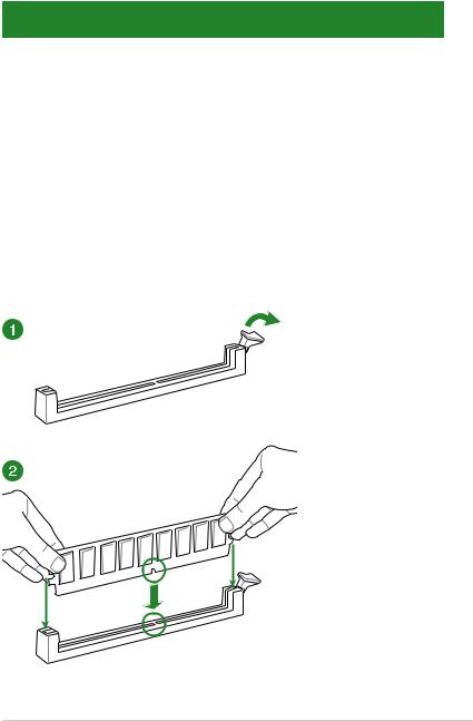
DDR3 1333 MHz capability
|
Vendors |
Part No. |
Size |
SS/DS |
Chip Brand |
Chip NO. |
Timing |
Voltage |
DIMM socket |
||
|
support (Optional) |
||||||||||
|
1 |
2 |
4 |
||||||||
|
Mach Xtreme |
MXD3U133316GQ |
16GB |
DS |
— |
— |
— |
— |
• |
• |
• |
|
(4x4GB) |
||||||||||
|
Mach Xtreme |
MXD3V13332GS |
2GB |
SS |
Mach |
C2S46D3 |
— |
— |
• |
• |
• |
|
Xtreme |
0-D313 |
|||||||||
|
MICRON |
MT8JTF25664AZ-1G4M1 |
2GB |
SS |
MICRON |
D9PFJ |
— |
— |
• |
• |
• |
|
Patriot |
PSD32G13332 |
2GB |
DS |
Prtriot |
PM128M8D |
9 |
— |
• |
• |
|
|
3BU-15 |
||||||||||
|
RiDATA |
C304627CB1AG22Fe |
2GB |
DS |
RiDATA |
C304627CB |
9 |
— |
• |
• |
• |
|
1AG22Fe |
||||||||||
|
RiDATA |
E304459CB1AG32Cf |
4GB |
DS |
RiDATA |
E304459CB |
9 |
— |
• |
• |
• |
|
1AG32Cf |
||||||||||
|
Silicon Power |
SP001GBLTU133S02 |
1GB |
SS |
S-POWER |
10YT3E5 |
9 |
— |
• |
• |
• |
|
Silicon Power |
SP002GBLTU133V02 |
2GB |
SS |
S-POWER |
20YT3NG |
9-9-9-24 |
— |
• |
• |
• |
|
Silicon Power |
SP004GBLTU133V02 |
4GB |
DS |
S-POWER |
20YT3NG |
9-9-9-24 |
— |
• |
• |
• |
|
UMAX |
84E44G93UM-13BPSYW |
4GB |
SS |
UMAX |
U2S96D3 |
1333-9- |
— |
• |
• |
• |
|
0TP-13 |
9-9-24 |
|||||||||
|
UMAX |
84E48G93UM-13BPSYW |
8GB |
DS |
UMAX |
U2S96D3 |
1333-9- |
— |
• |
• |
• |
|
0TP-13 |
9-9-24 |
1.4.3DIMM installation
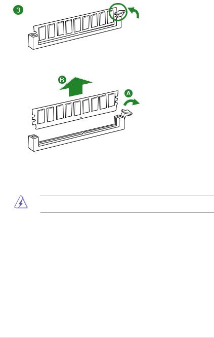
To remove a DIMM
1.5Expansion slots
In the future, you may need to install expansion cards. The following sub sections describe the slots and the expansion cards that they support.
Unplug the power cord before adding or removing expansion cards. Failure to do so may cause you physical injury and damage motherboard components.
1.5.1Installing an expansion card
To install an expansion card:
1.Before installing the expansion card, read the documentation that came with it and make the necessary hardware settings for the card.
2.Remove the system unit cover (if your motherboard is already installed in a chassis).
3.Remove the bracket opposite the slot that you intend to use. Keep the screw for later use.
4.Align the card connector with the slot and press firmly until the card is completely seated on the slot.
5.Secure the card to the chassis with the screw you removed earlier.
6.Replace the system cover.
|
1-20 |
Chapter 1: Product introduction |
![]()
1.5.2Configuring an expansion card
After installing the expansion card, configure it by adjusting the software settings:
1.Turn on the system and change the necessary BIOS settings, if any. See Chapter 2 for information on BIOS setup.
2.Assign an IRQ to the card.
3.Install the software drivers for the expansion card.
When using PCI cards on shared slots, ensure that the drivers support “Share IRQ” or that the cards do not need IRQ assignments. Otherwise, conflicts arise between the two PCI groups, making the system unstable and the card inoperable.
1.5.3PCI slots
The PCI slot supports cards such as a LAN card, SCSI card, USB card, and other cards that comply with PCI specifications.
1.5.4PCI Express 2.0 x1 slots
This motherboard supports PCI Express x1 network cards, SCSI cards, and other cards that comply with the PCI Express specifications.
1.5.5PCI Express 3.0 / 2.0 x16 slots
This motherboard supports PCI Express x16 network cards, SCSI cards, and other cards that comply with the PCI Express specifications.
Slot No. Expansion slot
PCIe 2.0 x1_1 slot
PCIe 3.0/2.0 x16_1 slot
PCI_1 slot
PCIe 2.0 x1_2 slot
PCIe 3.0/2.0 x16_2 slot
PCI_2 slot
PCIe 2.0 x16_3 slot

|
PCI Express 3.0 operating mode |
||||
|
VGA configuration |
PCIe 3.0/2.0 x16_1 |
PCIe 3.0/2.0 x16_2 |
||
|
Single VGA/PCIe card |
x16 (single VGA |
N/A |
||
|
recommended) |
||||
|
Dual VGA/PCIe card |
x8 |
x8 |
||
• We recommend that you provide sufficient power when running CrossFireX™ or SLI™ mode.
•Connect a chassis fan to the motherboard connector labeled CHA_FAN1-4 when using multiple graphics cards for better thermal environment.
IRQ assignments for this motherboard
|
A |
B |
C |
D |
E |
F |
G |
H |
||
|
I.G.D. |
Shared |
– |
– |
– |
– |
– |
– |
– |
|
|
HD Audio 1 Controller |
Shared |
– |
– |
– |
– |
– |
– |
||
|
HD Audio 2 Controller |
– |
– |
– |
– |
– |
Shared |
– |
||
|
EHCI 1 Controller |
– |
– |
– |
– |
– |
– |
– |
Shared |
|
|
EHCI 2 Controller |
Shared |
– |
– |
– |
– |
– |
– |
– |
|
|
XHCI Controller |
– |
– |
– |
– |
– |
Shared |
– |
– |
|
|
SATA Controller |
– |
– |
– |
Shared |
– |
– |
– |
– |
|
|
PCIE x16_1 |
Shared |
– |
– |
– |
– |
– |
– |
– |
|
|
PCIE x16_2 |
Shared |
– |
– |
– |
– |
– |
– |
||
|
PCIE x1_1 |
– |
Shared |
– |
– |
– |
– |
– |
||
|
PCIE x1_2 |
– |
– |
Shared |
– |
– |
– |
– |
||
|
Intel LAN |
– |
– |
– |
– |
Shared |
– |
– |
– |
|
|
PCI Slot 1 |
– |
– |
– |
Shared |
– |
– |
– |
– |
|
|
PCI Slot 2 |
Shared |
– |
– |
– |
– |
– |
– |
– |
|
1-22 |
Chapter 1: Product introduction |

1.6Jumpers
1.Clear RTC RAM (3-pin CLRTC)
This jumper allows you to clear the Real Time Clock (RTC) RAM in CMOS. You can clear the CMOS memory of date, time, and system setup parameters by erasing the CMOS RTC RAM data. The onboard button cell battery powers the RAM data in CMOS, which include system setup information such as system passwords.
To erase the RTC RAM:
1.Turn OFF the computer and unplug the power cord.
2.Move the jumper cap from pins 1-2 (default) to pins 2-3. Keep the cap on pins 2-3 for about 5-10 seconds, then move the cap back to pins 1-2.
3.Plug the power cord and turn ON the computer.
4.Hold down the <Del> key during the boot process and enter BIOS setup to reenter data.
Except when clearing the RTC RAM, never remove the cap on CLRTC jumper default position. Removing the cap will cause system boot failure!
• If the steps above do not help, remove the onboard battery and move the jumper again to clear the CMOS RTC RAM data. After clearing the CMOS, reinstall the battery.
•You do not need to clear the RTC when thae system hangs due to overclocking. For system failure due to overclocking, use the CPU Parameter Recall (C.P.R.) feature. Shut down and reboot the system, then the BIOS automatically resets parameter settings to default values.
•Due to chipset behavior, AC power off is required to enable C.P.R. function. You must turn off and on the power supply or unplug and plug the power cord before rebooting the system.

2.CPU Over Voltage jumper (3-pin CPU_OV)
The CPU Over Voltage jumper allows you to set a higher CPU voltage for a flexible overclocking system, depending on the type of the installed CPU. To gain more CPU voltage setting, insert the jumper to pins 2-3. To go back to its default CPU voltage setting, insert the jumper to pins 1-2.
|
1-24 |
Chapter 1: Product introduction |

1.7Connectors
1.7.1Rear panel connectors
Rear panel connectors
|
1. |
DisplayPort |
7. |
DVI-D port |
|
2. |
VGA port |
8. |
USB 3.0 ports 56 |
|
3. |
USB 2.0 ports 7-8 |
9. |
USB 3.0 ports 34 |
|
4. |
PS/2 keyboard/mouse port |
10. |
Optical S/PDIF Out port |
|
5. |
LAN port* |
11. |
Audio I/O ports** |
|
6. |
HDMI port |
||
* and **: Refer to the tables on the next page for LAN port LEDs and audio port definitions.
 Loading…