- Manuals
- Brands
- Gigabyte Manuals
- Motherboard
- B550 AORUS MASTER
- User manual
-
Contents
-
Table of Contents
-
Bookmarks
Quick Links
B550 AORUS MASTER
User’s Manual
Rev. 1001
12ME-B55AMST-1001R
For more product details, please visit GIGABYTE’s website.
To reduce the impacts on global warming, the packaging materials of this product
are recyclable and reusable. GIGABYTE works with you to protect the environment.
Related Manuals for Gigabyte B550 AORUS MASTER
Summary of Contents for Gigabyte B550 AORUS MASTER
-
Page 1
B550 AORUS MASTER User’s Manual Rev. 1001 12ME-B55AMST-1001R For more product details, please visit GIGABYTE’s website. To reduce the impacts on global warming, the packaging materials of this product are recyclable and reusable. GIGABYTE works with you to protect the environment. -
Page 2
GIGABYTE’s prior written permission. Documentation Classifications In order to assist in the use of this product, GIGABYTE provides the following types of documentations: „ For quick set-up of the product, read the Quick Installation Guide included with the product. -
Page 3: Table Of Contents
Table of Contents B550 AORUS MASTER Motherboard Layout …………..4 B550 AORUS MASTER Motherboard Block Diagram ………….5 Chapter 1 Hardware Installation ………………6 Installation Precautions ………………6 Product Specifications ………………7 Installing the CPU ………………11 Installing the Memory ………………11 Installing an Expansion Card …………….. 12 Back Panel Connectors ………………
-
Page 4: B550 Aorus Master Motherboard Layout
B550 AORUS MASTER Motherboard Layout ATX_12V2 CPU_OPT D_LED2 LED_C2 ATX_12V1 NOISE_ CPU_FAN USB20 SENSOR SYS_FAN1 M2_WIFI DB_PORT (Note) Socket AM4 USB_HDMI USB 2.0 Hub U32G2_1 QFLED QFLASH_PLUS U32G2_2 U32G2C U32G2_LAN LED_CPU AUDIO M_BIOS B_BIOS Realtek ® 2.5GbE LAN PCIEX16 CPU DRAM…
-
Page 5: B550 Aorus Master Motherboard Block Diagram
B550 AORUS MASTER Motherboard Block Diagram PCI Express 4.0/3.0 Bus CPU CLK+/- (100~500 MHz) Switch DDR4 3200/2933/2667/2400/2133 MHz 1 M.2 Socket 3 (M2A_CPU) AMD Socket 2 M.2 Socket 3 AM4 CPU (M2B_CPU/ HDMI Dual BIOS M2C_CPU) 4 USB 3.2 Gen 2 Type A ®…
-
Page 6: Chapter 1 Hardware Installation
Chapter 1 Hardware Installation Installation Precautions The motherboard contains numerous delicate electronic circuits and components which can become damaged as a result of electrostatic discharge (ESD). Prior to installation, carefully read the user’s manual and follow these procedures: • Prior to installation, make sure the chassis is suitable for the motherboard. •…
-
Page 7: Product Specifications
Support for non-ECC Un-buffered DIMM 1Rx8/2Rx8/1Rx16 memory modules Š Support for Extreme Memory Profile (XMP) memory modules Š (Go to GIGABYTE’s website for the latest supported memory speeds and memory modules.) Onboard Integrated in the New Generation AMD Ryzen with Radeon Graphics processors: ™…
-
Page 8
Storage Interface Š 1 x M.2 connector (M2A_CPU), integrated in the CPU, supporting Socket 3, M key, type 2242/2280/22110 SSDs: 3rd Generation AMD Ryzen processors support SATA and PCIe 4.0 x4/x2 ™ SSDs New Generation AMD Ryzen with Radeon Graphics processors support ™… -
Page 9
Back Panel 2 x SMA antenna connectors (2T2R) Š Connectors 1 x HDMI port Š 6 x USB 2.0/1.1 ports Š 5 x USB 3.2 Gen 2 Type-A ports (red) Š 1 x USB Type-C port, with USB 3.2 Gen 2 support ™… -
Page 10
System Form Factor ATX Form Factor; 30.5cm x 24.4cm Š * GIGABYTE reserves the right to make any changes to the product specifications and product-related information without prior notice. Please visit the SupportUtility List Please visit GIGABYTE’s website for support lists of CPU, memory page on GIGABYTE’s website to modules, SSDs, and M.2 devices. -
Page 11: Installing The Cpu
• Make sure that the motherboard supports the memory. It is recommended that memory of the same capacity, brand, speed, and chips be used. (Go to GIGABYTE’s website for the latest supported memory speeds and memory modules.) • Always turn off the computer and unplug the power cord from the power outlet before installing the memory to prevent hardware damage.
-
Page 12: Installing An Expansion Card
Recommanded Dual Channel Memory Configuration: DDR4_A1 DDR4_A2 DDR4_B1 DDR4_B2 2 Modules DS/SS DS/SS 4 Modules DS/SS DS/SS DS/SS DS/SS (SS=Single-Sided, DS=Double-Sided, «- -«=No Memory) Due to CPU limitations, read the following guidelines before installing the memory in Dual Channel mode. Dual Channel mode cannot be enabled if only one memory module is installed.
-
Page 13
Mic In/Side Speaker Out The Mic in jack. (Note 1) For new Generation AMD Ryzen with Radeon Graphics processors only. ™ ™ (Note 2) To enable the Q-Flash Plus function please visit the «Unique Features» webpage of GIGABYTE’s website. — 13 -… -
Page 14
If you want to install a Side Speaker, you need to retask either the Line in or Mic in jack to be Side Speaker out through the audio driver. Please visit GIGABYTE’s website for details on configuring the audio software. — 14 -… -
Page 15: Internal Connectors
Internal Connectors 8 10 ATX_12V1/ATX_12V2 SATA3 0/1/2/3/4/5 M2A_CPU/M2B_CPU/M2C_CPU CPU_FAN F_PANEL SYS_FAN1/2/3/4 F_AUDIO SYS_FAN5_PUMP/SYS_FAN6_PUMP F_U32 CPU_OPT F_USB1/F_USB2 EC_TEMP1/EC_TEMP2 D_LED1/D_LED2 CLR_CMOS LED_CPU LED_C1/LED_C2 CPU/DRAM/VGA/BOOT NOISE_SENSOR Read the following guidelines before connecting external devices: • First make sure your devices are compliant with the connectors you wish to connect. •…
-
Page 16
1/2) ATX_12V1/ATX_12V2/ATX (2×2, 2×4, 12V Power Connectors and 2×12 Main Power Connector) With the use of the power connector, the power supply can supply enough stable power to all the components on the motherboard. Before connecting the power connector, first make sure the power supply is turned off and all devices are properly installed. -
Page 17
3/4) CPU_FAN/SYS_FAN1/2/3/4 (Fan Headers) All fan headers on this motherboard are 4-pin. Most fan headers possess a foolproof insertion design. When connecting a fan cable, be sure to connect it in the correct orientation (the black connector wire is the ground wire). The speed control function requires the use of a fan with fan speed control design. For optimum heat dissipation, it is recommended that a system fan be installed inside the chassis. -
Page 18
LED strip. For how to turn on/off the lights of the LED strip please visit the «Unique Features» webpage of GIGABYTE’s website. Before installing the devices, be sure to turn off the devices and your computer. Unplug the power cord from the power outlet to prevent damage to the devices. -
Page 19
Cable For more information on the noise detection function, please visit the «Unique Features» webpage of GIGABYTE’s website. Before connecting the cable to the header, make sure to remove the jumper cap; re-place the jumper cap if the header is not in use. -
Page 20
S B_ 12) SATA3 0/1/2/3/4/5 (SATA 6Gb/s Connectors) F_USB3 F The SATA connectors conform to SATA 6Gb/s standard and are compatible with SATA 3Gb/s and SATA 1.5Gb/s standard. Each SATA connector supports a single SATA device. The SATA connectors support RAID 0, RAID 1, and RAID 10. -
Page 21
14) F_PANEL (Front Panel Header) Connect the power switch, reset switch, speaker, chassis intrusion switch/sensor and system status indicator on the chassis to this header according to the pin assignments below. Note the positive and negative pins before connecting the cables. •… -
Page 22
16) F_U32 (USB 3.2 Gen 1 Header) The header conforms to USB 3.2 Gen 1 and USB 2.0 specification and can provide two USB ports. For purchasing the optional 3.5″ front panel that provides two USB 3.2 Gen 1 ports, please contact the local dealer. -
Page 23
B S S 19) CLR_CMOS (Clear CMOS Jumper) Use this jumper to clear the BIOS configuration and reset the CMOS values to factory defaults. To clear the CMOS values, use a metal object like a screwdriver to touch the two pins for a few seconds. F_USB3 F Open: Normal Short: Clear CMOS Values… -
Page 24: Chapter 2 Bios Setup
To access the BIOS Setup program, press the <Delete> key during the POST when the power is turned on. To upgrade the BIOS, use either the GIGABYTE Q-Flash or @BIOS utility. Q-Flash allows the user to quickly and easily upgrade or back up BIOS without entering the operating system.
-
Page 25: The Main Menu
The Main Menu System Setup Menus Time Configuration Items Hardware Information Option Description Current Settings Quick Access Bar allows you to quickly move to the General Help, Easy Mode, Smart Fan 5, or Q-Flash screen. Advanced Mode Function Keys <f><g> Move the selection bar to select a setup menu <h><i>…
-
Page 26: Favorites (F11)
Favorites (F11) Set your frequently used options as your favorites and use the <F11> key to quickly switch to the page where all of your favorite options are located. To add or remove a favorite option, go to its original page and press <Insert>…
-
Page 27: Tweaker
Tweaker Whether the system will work stably with the overclock/overvoltage settings you made is dependent on your overall system configurations. Incorrectly doing overclock/overvoltage may result in damage to CPU, chipset, or memory and reduce the useful life of these components. This page is for advanced users only and we recommend you not to alter the default settings to prevent system instability or other unexpected results.
-
Page 28
ƒ Advanced CPU Settings & Core Performance Boost (Note 1) Allows you to determine whether to enable the Core Performance Boost (CPB) technology, a CPU performance-boost technology. (Default: Auto) & SVM Mode Virtualization enhanced by Virtualization Technology will allow a platform to run multiple operating systems and applications in independent partitions. -
Page 29
ƒ Advanced Memory Settings ƒ Memory Subtimings d Standard Timing Control, Advanced Timing Control, CAD Bus Setup Timing, CAD Bus Drive Strength, Data Bus Configuration These sections provide memory timing settings. Note: Your system may become unstable or fail to boot after you make changes on the memory timings. -
Page 30: Settings
Settings ƒ Platform Power & AC BACK Determines the state of the system after the return of power from an AC power loss. The system returns to its last known awake state upon the return of the AC power. Memory Always On The system is turned on upon the return of the AC power.
-
Page 31
ƒ IO Ports & Initial Display Output Specifies the first initiation of the monitor display from the installed PCI Express graphics card or the onboard graphics. IGD Video Sets the onboard graphics as the first display. (Note) PCIe 1 Slot Sets the graphics card on the PCIEX16 slot as the first display. -
Page 32
ƒ USB Configuration & Legacy USB Support Allows USB keyboard/mouse to be used in MS-DOS. (Default: Enabled) & XHCI Hand-off Determines whether to enable XHCI Hand-off feature for an operating system without XHCI Hand-off support. (Default: Enabled) & USB Mass Storage Driver Support Enables or disables support for USB storage devices. -
Page 33
& PXE boot wait time Allows you to configure how long to wait before you can press <Esc> to abort the PXE boot. This item is configurable only when Network Stack is enabled. (Default: 0) & Media detect count Allows you to set the number of times to check the presence of media. This item is configurable only when Network Stack is enabled. -
Page 34
& CPU Vcore/CPU VDDP/CPU VDD18/DDRVtt A/B/DRAM Channel A/B Voltage/PM_CLDO12/ +3.3V/+5V/CHIPSET Core/+12V/VCORE SOC Displays the current system voltages. ƒ Smart Fan 5 & Monitor Allows you to select a target to monitor and to make further adjustment. (Default: CPU FAN) & Fan Speed Control Allows you to determine whether to enable the fan speed control function and adjust the fan speed. -
Page 35: System Info
System Info. This section provides information on your motherboard model and BIOS version. You can also select the default language used by the BIOS and manually set the system time. & System Language Selects the default language used by the BIOS. &…
-
Page 36: Boot
System (Default) & Full Screen LOGO Show Allows you to determine whether to display the GIGABYTE Logo at system startup. Disabled skips the GIGABYTE Logo when the system starts up. (Default: Enabled) & Fast Boot Enables or disables Fast Boot to shorten the OS boot process. Ultra Fast provides the fastest bootup speed.
-
Page 37
& VGA Support Allows you to select which type of operating system to boot. Enables legacy option ROM only. Auto EFI Driver Enables EFI option ROM. (Default) This item is configurable only when Fast Boot is set to Enabled or Ultra Fast. &… -
Page 38
& User Password Allows you to configure a user password. Press <Enter> on this item, type the password, and then press <Enter>. You will be requested to confirm the password. Type the password again and press <Enter>. You must enter the administrator password (or user password) at system startup and when entering BIOS Setup. -
Page 39: Save & Exit
Save & Exit & Save & Exit Setup Press <Enter> on this item and select Yes. This saves the changes to the CMOS and exits the BIOS Setup program. Select No or press <Esc> to return to the BIOS Setup Main Menu. &…
-
Page 40: Chapter 3 Appendix
Chapter 3 Appendix Configuring a RAID Set RAID Levels RAID 0 RAID 1 RAID 10 Minimum Number of ≥2 Hard Drives Number of hard drives * Size of the smallest drive (Number of hard drives/2) * Array Capacity Size of the smallest drive Size of the smallest drive Fault Tolerance Before you begin, please prepare the following items:…
-
Page 41
4. Select AMD-RAID Bottom Device first and click Next to load the driver. Then select AMD-RAID Controller and click Next to load the driver. Finally, continue the OS installation. Please visit GIGABYTE’s website for details on configuring a RAID array. — 41 -… -
Page 42: Drivers Installation
You can click the Xpress Install button and «Xpress Install» will install all of the selected drivers. Or click the arrow icon to individually install the drivers you need. Please visit GIGABYTE’s website for more software information. Please visit GIGABYTE’s website for more troubleshooting information. — 42 -…
-
Page 43: Debug Led Codes
Debug LED Codes Regular Boot Code Description PEI Core is started. Pre-memory CPU initialization is started. 12~14 Reserved. Pre-memory North-Bridge initialization is started. 16~18 Reserved. Pre-memory South-Bridge initialization is started. 1A~2A Reserved. 2B~2F Memory initialization. Memory installed. 32~36 CPU PEI initialization. 37~3A IOH PEI initialization.
-
Page 44
Code Description PCI Bus initialization is started. PCI Bus hot plug initialization. PCI Bus enumeration for detecting how many resources are requested. Check PCI device requested resources. Assign PCI device resources. Console Output devices connect (ex. Monitor is lighted). Console input devices connect (ex. PS2/USB keyboard/mouse are activated). Super IO initialization. -
Page 45
Code Description USB device hot plug-in. PCI device hot plug. Clean-up of NVRAM. Reconfigure NVRAM settings. B8~BF Reserved. C0~CF Reserved. S3 Resume Code Description S3 Resume is stared (called from DXE IPL). Fill boot script data for S3 resume. Initializes VGA for S3 resume. OS S3 wake vector call. -
Page 46
Code Description PCH initialization error. Some of the Architectural Protocols are not available. PCI resource allocation error. Out of Resources. No Space for Legacy Option ROM initialization. No Console Output Devices are found. No Console Input Devices are found. It is an invalid password. D9~DA Can’t load Boot Option. -
Page 47: Regulatory Notices
Supplier’s Declaration of Conformity 47 CFR § 2.1077 Compliance Information Product Name: Motherboard Trade Name: GIGABYTE Model Number: B550 AORUS MASTER Responsible Party – U.S. Contact Information: G.B.T. Inc. Address: 17358 Railroad street, City Of Industry, CA91748 Tel.: 1-626-854-9338 Internet contact information: https://www.gigabyte.com FCC Compliance Statement: This device complies with Part 15 of the FCC Rules, Subpart B, Unintentional Radiators.
-
Page 48
European Commission Delegated Directive (EU) 2015/863 Statement Este producto que llevan la marca CE cumplen con las siguientes GIGABYTE products have not intended to add and safe from hazardous Directivas de la Unión Europea: Directiva EMC 2014/30/EU, Directiva substances (Cd, Pb, Hg, Cr+6, PBDE, PBB, DEHP, BBP, DBP and DIBP). -
Page 49
European Community Directive RED Directive Compliance Statement: This equipment is suitable for home and office use in all the European Community Member States and EFTA Member States. The low band 5.15 -5.35 GHz is for indoor use only for the countries listed in the table below: Wireless module country approvals: Wireless module model name: AX200NGW… -
Page 50
— 50 -… -
Page 51
— 51 -… -
Page 52: Contact Us
Contact Us GIGA-BYTE TECHNOLOGY CO., LTD. Address: No.6, Baoqiang Rd., Xindian Dist., New Taipei City 231, Taiwan TEL: +886-2-8912-4000, FAX: +886-2-8912-4005 Tech. and Non-Tech. Support (Sales/Marketing) : https://esupport.gigabyte.com WEB address (English): https://www.gigabyte.com WEB address (Chinese): https://www.gigabyte.com/tw GIGABYTE eSupport • To submit a technical or non-technical (Sales/Marketing) question, please link to: https://esupport.gigabyte.com…
- Manuals
- Brands
- Gigabyte Manuals
- Motherboard
- B550 AORUS MASTER
Manuals and User Guides for Gigabyte B550 AORUS MASTER. We have 1 Gigabyte B550 AORUS MASTER manual available for free PDF download: User Manual
![]()
B550AORUSMASTER
User’s Manual
Rev. 1001
12ME-B55AMST-1001R
For more product details, please visit GIGABYTE’s website.
To reduce the impacts on global warming, the packaging materials of this product are recyclable and reusable. GIGABYTE works with you to protect the environment.

Copyright
© 2020 GIGA-BYTE TECHNOLOGY CO., LTD. All rights reserved.
The trademarks mentioned in this manual are legally registered to their respective owners.
Disclaimer
Information in this manual is protected by copyright laws and is the property of GIGABYTE.
Changes to the specifications and features in this manual may be made by GIGABYTE without prior notice.
No part of this manual may be reproduced, copied, translated, transmitted, or published in any form or by any means without GIGABYTE’s prior written permission.
Documentation Classifications
In order to assist in the use of this product, GIGABYTE provides the following types of
documentations:
For quick set-up of the product, read the Quick Installation Guide included with the product.For detailed product information, carefully read the User’s Manual.
For product-related information, check on our website at: https://www.gigabyte.com
Identifying Your Motherboard Revision
The revision number on your motherboard looks like this: «REV: X.X.» For example, «REV: 1.0» means the revision of the motherboard is 1.0. Check your motherboard revision before updating motherboard BIOS, drivers, or when looking for technical information.
Example:

Table of Contents
|
B550 AORUS MASTER Motherboard Layout………………………………………………………… |
4 |
|
|
B550 AORUS MASTER Motherboard Block Diagram…………………………………………….. |
5 |
|
|
Chapter 1 Hardware Installation………………………………………………………………………….. |
6 |
|
|
1-1 |
Installation Precautions…………………………………………………………………………. |
6 |
|
1-2 |
Product Specifications………………………………………………………………………….. |
7 |
|
1-3 |
Installing the CPU………………………………………………………………………………. |
11 |
|
1-4 |
Installing the Memory………………………………………………………………………….. |
11 |
|
1-5 Installing an Expansion Card……………………………………………………………….. |
12 |
|
|
1-6 |
Back Panel Connectors………………………………………………………………………. |
12 |
|
1-7 |
Internal Connectors……………………………………………………………………………. |
15 |
|
Chapter 2 BIOS Setup……………………………………………………………………………………… |
24 |
|
|
2-1 |
Startup Screen…………………………………………………………………………………… |
24 |
|
2-2 |
The Main Menu………………………………………………………………………………….. |
25 |
|
2-3 |
Favorites (F11)…………………………………………………………………………………… |
26 |
|
2-4 |
Tweaker……………………………………………………………………………………………. |
27 |
|
2-5 |
Settings…………………………………………………………………………………………….. |
30 |
|
2-6 |
System Info……………………………………………………………………………………….. |
35 |
|
2-7 |
Boot…………………………………………………………………………………………………. |
36 |
|
2-8 |
Save & Exit……………………………………………………………………………………….. |
39 |
|
Chapter 3 Appendix…………………………………………………………………………………………. |
40 |
|
|
3-1 Configuring a RAID Set………………………………………………………………………. |
40 |
|
|
3-2 |
Drivers Installation……………………………………………………………………………… |
42 |
|
3-3 |
Debug LED Codes……………………………………………………………………………… |
43 |
|
Regulatory Notices………………………………………………………………………………………. |
47 |
|
|
Contact Us………………………………………………………………………………………………….. |
52 |
— 3 —

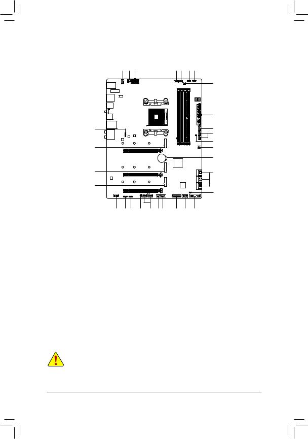
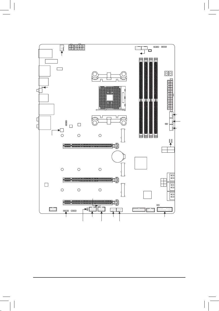
B550 AORUS MASTER Motherboard Layout
|
ATX_12V2 |
CPU_OPT |
D_LED2 LED_C2 |
|
|
USB20 |
ATX_12V1 |
CPU_FAN |
NOISE_ |
|
SYS_FAN1 |
SENSOR |
||
|
M2_WIFI |
|||
|
USB_HDMI USB 2.0 Hub |
Socket AM4 |
DB_PORT (Note) |
|
U32G2_1

 QFLED
QFLED
QFLASH_PLUS
U32G2_2
U32G2C
U32G2_LAN
LED_CPU
AUDIO
|
B_BIOS |
M_BIOS |
||
|
Realtek® |
110 |
80 |
42 |
|
2.5GbE LAN |
|||
|
PCIEX16 |
|
B550 AORUS MASTER |
||||
|
M2A CPU |
A1 |
A2 |
B1 |
B2 |
|
DDR4_ |
DDR4_ |
DDR4_ |
DDR4_ |
BAT
|
ATX |
||
|
EC TEMP1 |
FAN4 SYS FAN5 PUMP |
SYS FAN2 |
|
SYS_ |
||
|
CPU DRAM |
||
|
VGA BOOT |
CODEC
|
110 |
80 |
42 |
|
|
PCIEX4_2 |
USB 2.0 Hub |
||
|
F_AUDIO |
LED_C1 |
||
|
D_LED1 |
F_USB2 |
||
|
Box Contents |
EC_TEMP2 |
F_USB1 |
|
|
M2C_CPU |
iTE® |
|
Super I/O |
|
|
F_U32 |
TPM |
|
SYS_FAN3 |
|
|
SYS_FAN6_PUMP |
4 2 0 SATA3 5 3 1
 CLR_CMOS
F_PANEL
|
55 |
B550 AORUS MASTER motherboard |
55 |
One antenna |
|
55 |
Motherboard driver disc |
55 |
Four SATA cables |
|
55 |
User’s Manual |
55 |
Two thermistor cables |
|
55 |
Quick Installation Guide |
55 |
One noise detection cable |
|
55 |
One RGB LED strip extension cable |
55 |
Two Velcro cable ties |
|
55 |
One addressable LED strip adapter cable |
55 |
One G Connector |
*The box contents above are for reference only and the actual items shall depend on the product package you obtain. The box contents are subject to change without notice.
(Note) For debug code information, please refer to Chapter 3. — 4 —

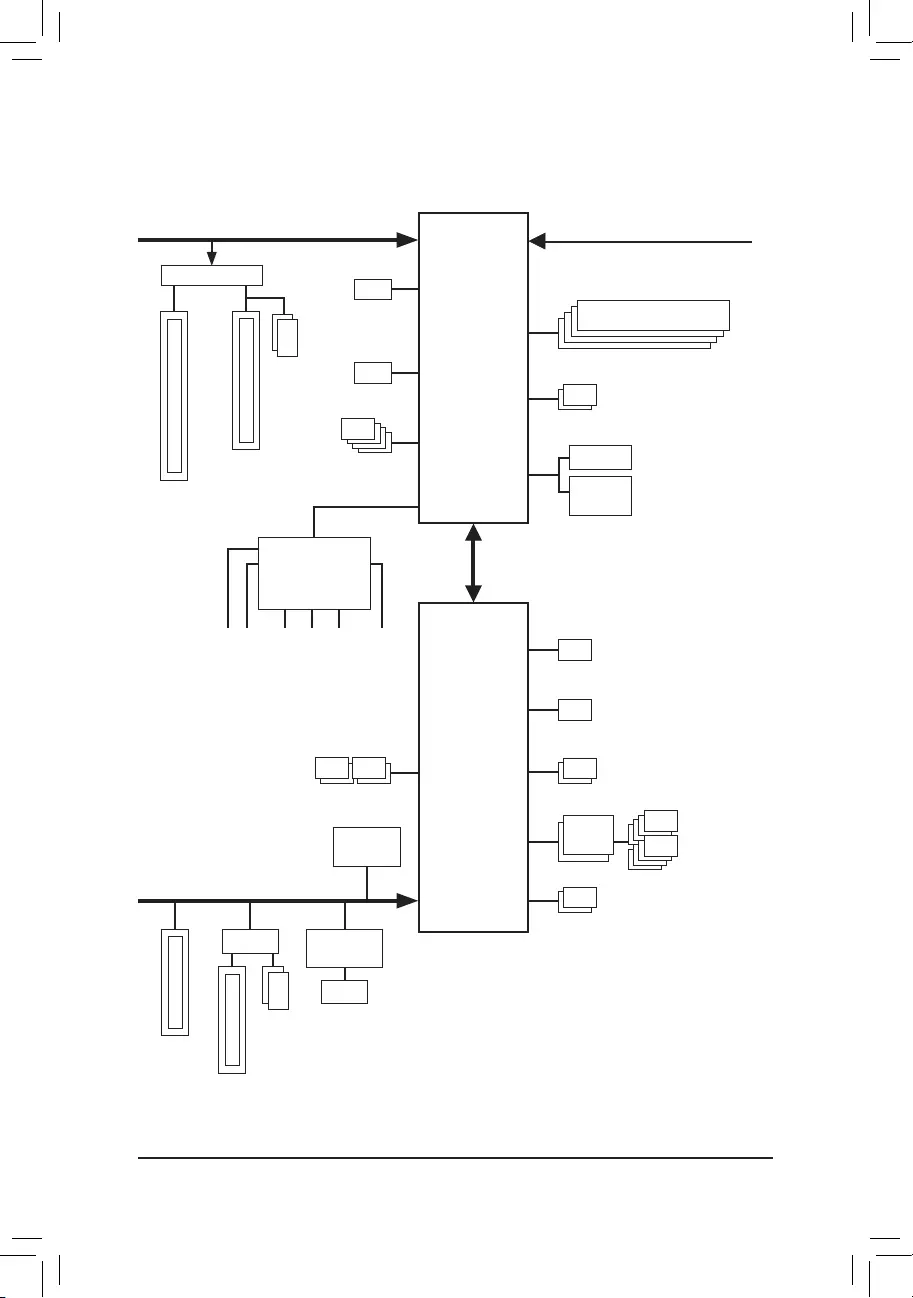
B550 AORUS MASTER Motherboard Block Diagram
|
PCI Express 4.0/3.0 Bus |
|||||||||||||||||||||||||||||
|
x16 |
|||||||||||||||||||||||||||||
|
Switch |
|||||||||||||||||||||||||||||
|
1 M.2 Socket 3 |
|||||||||||||||||||||||||||||
|
ExpressPCI1x16 |
ExpressPCI1x8 |
(M2A_CPU) |
|||||||||||||||||||||||||||
|
2 M.2 Socket 3 |
|||||||||||||||||||||||||||||
|
or |
(M2B_CPU/ |
||||||||||||||||||||||||||||
|
HDMI |
|||||||||||||||||||||||||||||
|
M2C_CPU) |
|||||||||||||||||||||||||||||
|
4 USB 3.2 Gen 2 |
|||||||||||||||||||||||||||||
|
Type A |
|||||||||||||||||||||||||||||
|
CODEC |
|||||||||||||||||||||||||||||
CPU CLK+/- (100~500 MHz)
DDR4 3200/2933/2667/2400/2133 MHz
|
AMD Socket |
||||||||||||||||
|
AM4 CPU |
SPI |
Dual BIOS |
||||||||||||||
|
Bus |
||||||||||||||||
|
LPC |
TPM |
|||||||||||||||
|
Bus |
iTE® |
|||||||||||||||
|
Super I/O |
||||||||||||||||
|
PCIe 3.0 x4 |
||||||||||||||||
|
SpeakerRearOut Center/Subwoofer |
MIC Line Out Line In |
S/PDIFOut |
|
SpeakerOut |
4 SATA 6Gb/s 

(SATA3 0~3) 


|
M.2 WIFI |
|||||||||||||||||||
|
Module |
|||||||||||||||||||
|
PCI Express 3.0 Bus |
x1 |
||||||||||||||||||
|
x4 |
x1 |
||||||||||||||||||
|
Switch |
Realtek® |
||||||||||||||||||
|
x4 |
2.5GbE LAN |
||||||||||||||||||
|
or |
|||||||||||||||||||
|
Express |
RJ45 |
||||||||||||||||||
|
LAN |
|||||||||||||||||||
|
2 SATA 6Gb/s |
|||||||||||||||||||
|
1 x PCI |
(SATA3 4/5) |
||||||||||||||||||
|
1 USB Type-C™, |
|||||||||||||||||
|
USB 3.2 Gen 2 |
|||||||||||||||||
|
1 USB 3.2 Gen 2 |
|||||||||||||||||
|
AMD B550 |
Type A |
||||||||||||||||
|
2 USB 3.2 Gen 1 |
|||||||||||||||||
|
USB 2.0 |
8 USB 2.0/1.1 |
||||||||||||||||
|
Hub |
|||||||||||||||||
|
2 USB 2.0/1.1 |
|||||||||||||||||
— 5 —

Chapter 1 Hardware Installation
1-1 Installation Precautions
The motherboard contains numerous delicate electronic circuits and components which can become damaged as a result of electrostatic discharge (ESD). Prior to installation, carefully read the user’s manual and follow these procedures:
•• Prior to installation, make sure the chassis is suitable for the motherboard.
•• Prior to installation, do not remove or break motherboard S/N (Serial Number) sticker or warranty sticker provided by your dealer. These stickers are required for warranty validation.
•• Always remove the AC power by unplugging the power cord from the power outlet before installing or removing the motherboard or other hardware components.
•• When connecting hardware components to the internal connectors on the motherboard, make sure they are connected tightly and securely.
•• When handling the motherboard, avoid touching any metal leads or connectors.
•• It is best to wear an electrostatic discharge (ESD) wrist strap when handling electronic components such as a motherboard, CPU or memory. If you do not have an ESD wrist strap, keep your hands dry and first touch a metal object to eliminate static electricity.
•• Prior to installing the motherboard, please have it on top of an antistatic pad or within an electrostatic shielding container.
•• Before connecting or unplugging the power supply cable from the motherboard, make sure the power supply has been turned off.
•• Before turning on the power, make sure the power supply voltage has been set according to the local voltage standard.
•• Before using the product, please verify that all cables and power connectors of your hardware components are connected.
•• To prevent damage to the motherboard, do not allow screws to come in contact with the motherboard circuit or its components.
•• Make sure there are no leftover screws or metal components placed on the motherboard or within the computer casing.
•• Do not place the computer system on an uneven surface.
•• Do not place the computer system in a high-temperature or wet environment.
•• Turning on the computer power during the installation process can lead to damage to system components as well as physical harm to the user.
•• If you are uncertain about any installation steps or have a problem related to the use of the product, please consult a certified computer technician.
•• If you use an adapter, extension power cable, or power strip, ensure to consult with its installation and/or grounding instructions.
— 6 —

1-2 Product Specifications
|
CPU |
AMD Socket AM4, support for: |
||
|
3rd Generation AMD Ryzen™ processors/ |
|||
|
New Generation AMD Ryzen™ with Radeon™ Graphics processors |
|||
|
(Go to GIGABYTE’s website for the latest CPU support list.) |
|||
|
Chipset |
AMD B550 |
||
|
Memory |
4 x DDR4 DIMM sockets supporting up to 128 GB (32 GB single DIMM capacity) |
||
|
of system memory |
|||
|
Support for DDR4 3200/2933/2667/2400/2133 MHz memory modules |
|||
|
Dual channel memory architecture |
|||
|
Support for ECC Un-buffered DIMM 1Rx8/2Rx8 memory modules |
|||
|
Support for non-ECC Un-buffered DIMM 1Rx8/2Rx8/1Rx16 memory modules |
|||
|
Support for Extreme Memory Profile (XMP) memory modules |
|||
|
(Go to GIGABYTE’s website for the latest supported memory speeds and memory |
|||
|
modules.) |
|||
|
Onboard |
Integrated in the New Generation AMD Ryzen™ with Radeon™ Graphics processors: |
||
|
Graphics |
— 1 x HDMI port, supporting a maximum resolution of 4096×2160@60 Hz |
||
|
* |
Support for HDMI 2.1 version, HDCP 2.3, and HDR. |
||
|
Maximum shared memory of 16 GB |
|||
|
Audio |
Realtek® ALC1220-VB codec |
||
|
* |
The back panel line out jack supports DSD audio. |
||
|
Support for DTS:X® Ultra |
|||
|
High Definition Audio |
|||
|
2/4/5.1/7.1-channel |
|||
|
Support for S/PDIF Out |
|||
|
LAN |
Realtek® 2.5GbE LAN chip (2.5 Gbit/1 Gbit/100 Mbit) |
||
|
Wireless |
Intel® Wi-Fi 6 AX200 |
||
|
Communication |
— WIFI a, b, g, n, ac with wave 2 features, ax, supporting 2.4/5 GHz Dual-Band |
||
|
Module |
— BLUETOOTH 5 |
||
|
— Support for 11ax 160MHz wireless standard and up to 2.4 Gbps data rate |
|||
|
* |
Actual data rate may vary depending on environment and equipment. |
||
|
Expansion Slots |
1 x PCI Express x16 slot (PCIEX16), integrated in the CPU: |
||
|
— 3rd Generation AMD Ryzen™ processors support PCIe 4.0 x16 mode |
|||
|
— New Generation AMD Ryzen™ with Radeon™ Graphics processors support |
|||
|
PCIe 3.0 x16 mode |
|||
|
* |
For optimum performance, if only one PCI Express graphics card is to be installed, |
||
|
be sure to install it in the PCIEX16 slot. |
|||
|
* |
The PCIEX16 slot shares bandwidth with the M2B_CPU and M2C_CPU connectors. |
||
|
The PCIEX16 slot operates at up to x8 mode when a device is installed in the |
|||
|
M2B_CPU or M2C_CPU connector. |
2 x PCI Express x16 slots (PCIEX4_1/PCIEX4_2), integrated in the Chipset:
—Supporting PCIe 3.0 x4 mode
*The PCIEX4_2 slot shares bandwidth with the SATA3 4, 5 connectors. The PCIEX4_2 slot operates at up to x2 mode when a device is installed in the SATA3 4 or SATA3 5 connector.
— 7 —
Storage Interface 1 x M.2 connector (M2A_CPU), integrated in the CPU, supporting Socket 3, M key, type 2242/2280/22110 SSDs:
—3rd Generation AMD Ryzen™ processors support SATA and PCIe 4.0 x4/x2 SSDs
—New Generation AMD Ryzen™ with Radeon™ Graphics processors support SATA and PCIe 3.0 x4/x2 SSDs
2 x M.2 connectors (M2B_CPU/M2C_CPU), integrated in the CPU, supporting Socket 3, M key, type 2242/2280/22110 SSDs:
—3rd Generation AMD Ryzen™ processors support PCIe 4.0 x4/x2 SSDs
—New Generation AMD Ryzen™ with Radeon™ Graphics processors support PCIe 3.0 x4/x2 SSDs
6 x SATA 6Gb/s connectors, integrated in the Chipset:
|
— Support for RAID 0, RAID 1, and RAID 10 |
|||
|
USB |
CPU: |
||
|
— 4 x USB 3.2 Gen 2 Type-A ports (red) on the back panel |
|||
|
Chipset: |
|||
|
— 1 x USB Type-C™ port on the back panel, with USB 3.2 Gen 2 support |
|||
|
— 1 x USB 3.2 |
Gen 2 Type-A port (red) on the back panel |
||
|
— 2 x USB 3.2 |
Gen 1 ports available through the internal USB header |
—2 x USB 2.0/1.1 ports on the back panelChipset+2 USB 2.0 Hubs:
—8 x USB 2.0/1.1 ports (4 ports on the back panel, 4 ports available through the internal USB headers)
|
Internal |
1 x 24-pin ATX main power connector |
|
Connectors |
1 x 8-pin ATX 12V power connector |
|
1 x 4-pin ATX 12V power connector |
|
|
1 x CPU fan header |
|
|
1 x water cooling CPU fan header |
|
|
4 x system fan headers |
|
|
2 x system fan/water cooling pump headers |
|
|
2 x addressable LED strip headers |
|
|
2 x RGB LED strip headers |
|
|
1 x CPU cooler LED strip/RGB LED strip header |
|
|
3 x M.2 Socket 3 connectors |
|
|
6 x SATA 6Gb/s connectors |
|
|
1 x front panel header |
|
|
1 x front panel audio header |
|
|
1 x USB 3.2 Gen 1 header |
|
|
2 x USB 2.0/1.1 headers |
|
|
1 x noise detection header |
|
|
1 x Trusted Platform Module (TPM) header (2×6 pin, for the GC-TPM2.0_S |
|
|
module only) |
|
|
1 x Clear CMOS jumper |
|
|
2 x temperature sensor headers |
— 8 —
|
Back Panel |
2 x SMA antenna connectors (2T2R) |
||
|
Connectors |
1 x HDMI port |
||
|
6 x USB 2.0/1.1 ports |
|||
|
5 x USB 3.2 Gen 2 Type-A ports (red) |
|||
|
1 x USB Type-C™ port, with USB 3.2 Gen 2 support |
|||
|
1 x Q-Flash Plus button |
|||
|
1 x RJ-45 port |
|||
|
1 x optical S/PDIF Out connector |
|||
|
5 x audio jacks |
|||
|
I/O Controller |
iTE® I/O Controller Chip |
||
|
Hardware |
Voltage detection |
||
|
Monitor |
Temperature detection |
||
|
Fan speed detection |
|||
|
Water cooling flow rate detection |
|||
|
Overheating warning |
|||
|
Fan fail warning |
|||
|
Fan speed control |
|||
|
* Whether the fan (pump) speed control function is supported will depend on the fan |
|||
|
(pump) you install. |
|||
|
Noise detection |
|||
|
BIOS |
2 x 256 Mbit flash |
||
|
Use of licensed AMI UEFI BIOS |
|||
|
Support for DualBIOS™ |
|||
|
PnP 1.0a, DMI 2.7, WfM 2.0, SM BIOS 2.7, ACPI 5.0 |
|||
|
Unique Features |
Support for APP Center |
||
|
* Available applications in APP Center may vary by motherboard model. Supported |
|||
|
functionsofeachapplicationmayalsovarydependingonmotherboardspecifications. |
|||
|
— |
@BIOS |
||
|
— |
EasyTune |
||
|
— |
Fast Boot |
||
|
— |
Game Boost |
||
|
— |
ON/OFF Charge |
||
|
— |
RGB Fusion |
||
|
— |
Smart Backup |
||
|
— |
System Information Viewer |
||
|
Support for Q-Flash Plus |
|||
|
Support for Q-Flash |
|||
|
Support for Xpress Install |
— 9 —

|
Bundled |
Norton® Internet Security (OEM version) |
|
|
Software |
XSplit Gamecaster + Broadcaster (12 months license) |
|
|
Realtek® 8125 Gaming LAN Bandwidth Control Utility |
||
|
Operating |
Support for Windows 10 64-bit |
|
|
System |
||
|
Form Factor |
ATX Form Factor; 30.5cm x 24.4cm |
*GIGABYTE reserves the right to make any changes to the product specifications and product-related information without prior notice.
Please visit GIGABYTE’s website for support lists of CPU, memory modules, SSDs, and M.2 devices.
— 10 —
Please visit the SupportUtility List page on GIGABYTE’s website to download the latest version of apps.
![]()
|
1-3 |
Installing the CPU |
|
|
Read the following guidelines before you begin to install the CPU: |
||
|
•• |
Make sure that the motherboard supports the CPU. |
|
|
(Go to GIGABYTE’s website for the latest CPU support list.) |
||
|
•• |
Always turn off the computer and unplug the power cord from the power outlet before installing the |
|
|
CPU to prevent hardware damage. |
||
|
•• |
Locate the pin one of the CPU. The CPU cannot be inserted if oriented incorrectly. |
|
|
•• |
Apply an even and thin layer of thermal grease on the surface of the CPU. |
|
|
•• |
Do not turn on the computer if the CPU cooler is not installed, otherwise overheating and damage |
|
|
of the CPU may occur. |
||
|
•• |
Set the CPU host frequency in accordance with the CPU specifications. It is not recommended |
|
|
that the system bus frequency be set beyond hardware specifications since it does not meet the |
||
|
standard requirements for the peripherals. If you wish to set the frequency beyond the standard |
||
|
specifications, please do so according to your hardware specifications including the CPU, graphics |
||
|
card, memory, hard drive, etc. |
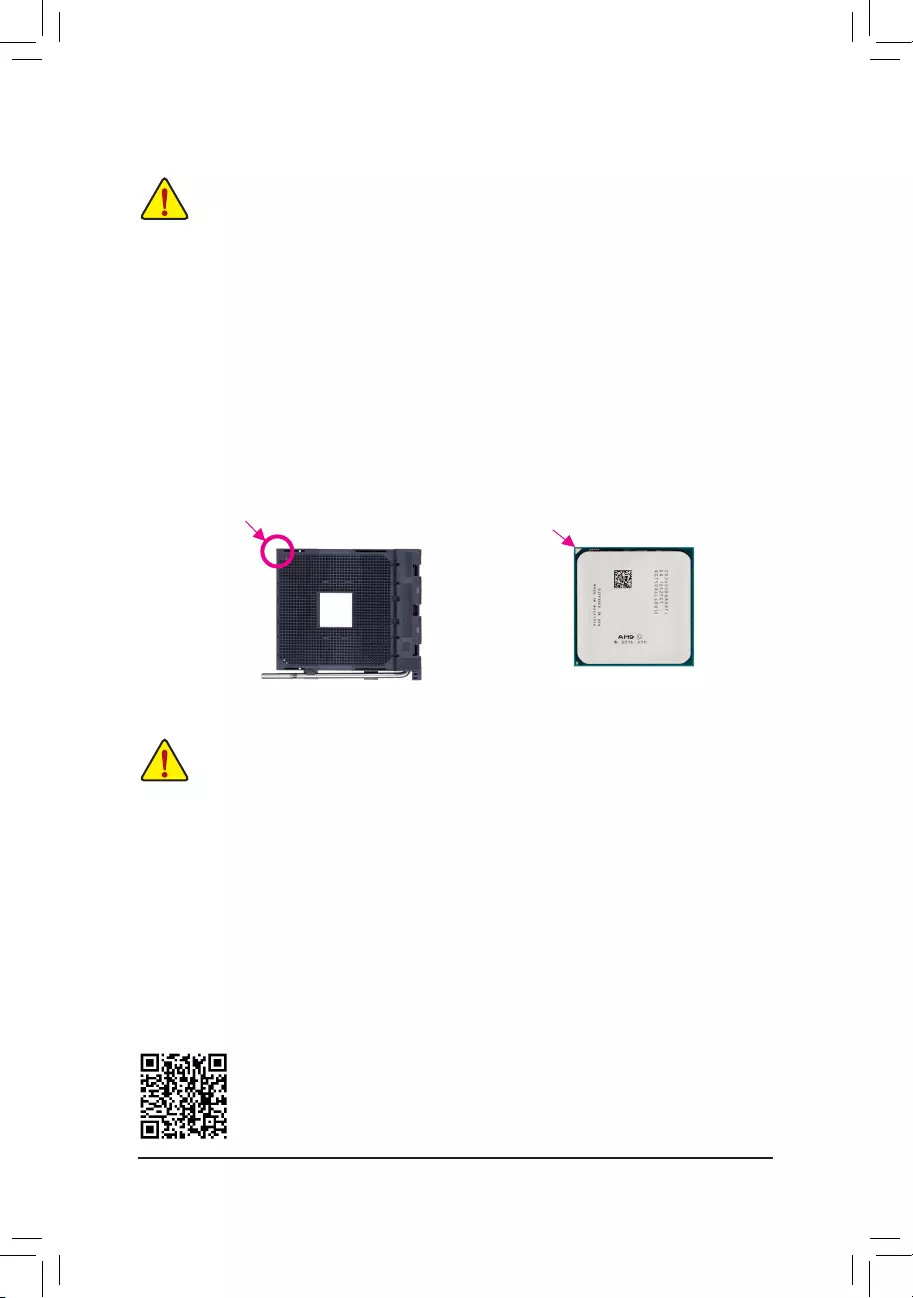
Installing the CPU
Locate the pin one (denoted by a small triangle) of the CPU socket and the CPU.
|
A Small Triangle |
A Small Triangle |
|||
|
Marking Denotes Pin |
AM4 Socket |
AM4 CPU |
||
|
Marking Denotes CPU |
||||
|
One of the Socket |
||||
|
Pin One |
||||
1-4 Installing the Memory
Read the following guidelines before you begin to install the memory:
•• Make sure that the motherboard supports the memory. It is recommended that memory of the same capacity, brand, speed, and chips be used.
(Go to GIGABYTE’s website for the latest supported memory speeds and memory modules.)
•• Always turn off the computer and unplug the power cord from the power outlet before installing the memory to prevent hardware damage.
•• Memory modules have a foolproof design. A memory module can be installed in only one direction. If you are unable to insert the memory, switch the direction.
Dual Channel Memory Configuration
This motherboard provides four memory sockets and supports Dual Channel Technology. After the memory is installed, the BIOS will automatically detect the specifications and capacity of the memory. Enabling Dual
Channel memory mode will double the original memory bandwidth.
The four memory sockets are divided into two channels and each channel has two memory sockets as following:
Channel A: DDR4_A1, DDR4_A2Channel B: DDR4_B1, DDR4_B2
Please visit GIGABYTE’s website for details on hardware installation.
— 11 —
Recommanded Dual Channel Memory Configuration:
|
DDR4_A1 |
DDR4_A2 |
DDR4_B1 |
DDR4_B2 |
|
|
2 Modules |
— — |
DS/SS |
— — |
DS/SS |
|
4 Modules |
DS/SS |
DS/SS |
DS/SS |
DS/SS |
(SS=Single-Sided, DS=Double-Sided, «- -«=No Memory)
Due to CPU limitations, read the following guidelines before installing the memory in Dual Channel mode.
1.Dual Channel mode cannot be enabled if only one memory module is installed.
2.When enabling Dual Channel mode with two or four memory modules, it is recommended that memory of the same capacity, brand, speed, and chips be used.
1-5 Installing an Expansion Card
Read the following guidelines before you begin to install an expansion card:
•• Make sure the motherboard supports the expansion card. Carefully read the manual that came with your expansion card.
•• Always turn off the computer and unplug the power cord from the power outlet before installing an expansion card to prevent hardware damage.
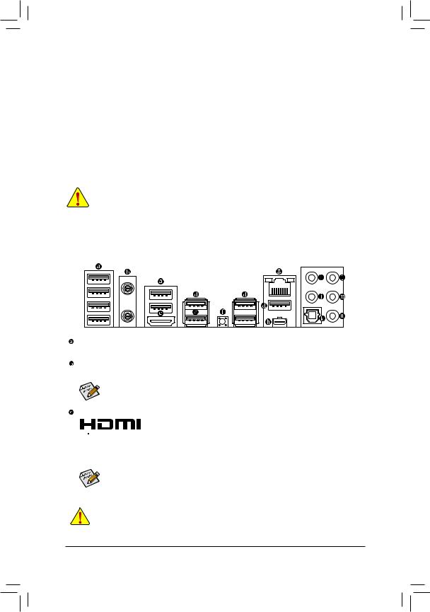
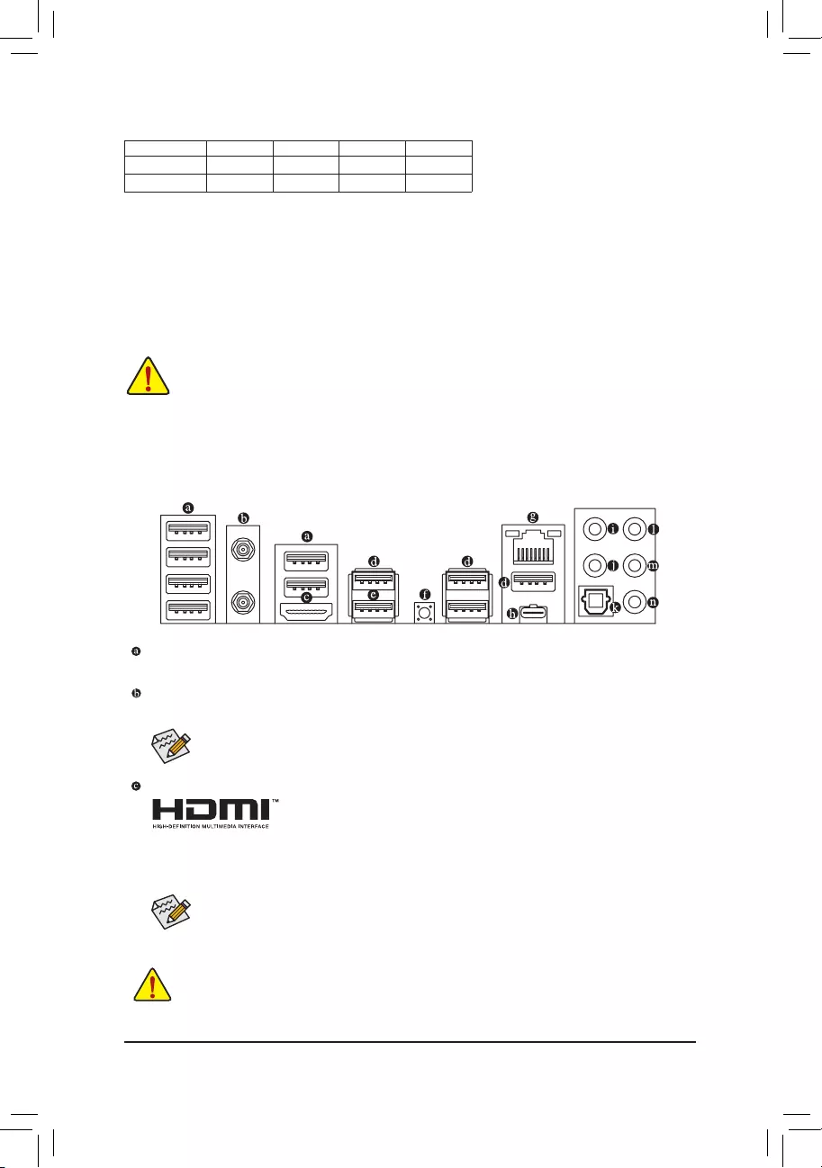
1-6 Back Panel Connectors
USB 2.0/1.1 Port
The USB port supports the USB 2.0/1.1 specification. Use this port for USB devices.
SMA Antenna Connectors (2T2R)
Use this connector to connect an antenna.
Tighten the antennas to the antenna connectors and then aim the antennas correctly for better signal reception.
HDMI Port (Note 1)
 The HDMI port is HDCP 2.3 compliant and supports Dolby TrueHD and DTS HD


 Master Audio formats. It also supports up to 192KHz/24bit 7.1-channel LPCM audio output. You can use this port to connect your HDMI-supported monitor. The maximum supported resolution is 4096×2160@60 Hz, but the actual resolutions supported are dependent on the monitor being used.
After installing the HDMI device, make sure to set the default sound playback device to HDMI. (The item name may differ depending on your operating system.)
•• When removing the cable connected to a back panel connector, first remove the cable from your device and then remove it from the motherboard.
•• When removing the cable, pull it straight out from the connector. Do not rock it side to side to prevent an electrical short inside the cable connector.
— 12 —

USB 3.2 Gen 2 Port
The USB 3.2 Gen 2 port supports the USB 3.2 Gen 2 specification and is compatible to the USB 3.2 Gen 1 and USB 2.0 specification. Use this port for USB devices.
USB 3.2 Gen 2 Port (Q-Flash Plus Port)
The USB 3.2 Gen 2 port supports the USB 3.2 Gen 2 specification and is compatible to the USB 3.2 Gen 1 and USB 2.0 specification. Use this port for USB devices. Before using Q-Flash Plus(Note 2), make sure to insert the USB flash drive into this port first.
Q-Flash Plus Button (Note 2)
Q-Flash Plus allows you to update the BIOS when your system is off (S5 shutdown state). Save the latest
BIOS on a USB thumb drive and plug it into the Q-Flash Plus port, and then you can now flash the BIOS automatically by simply pressing the Q-Flash Plus button. The QFLED will flash when the BIOS matching and flashing activities start and will stop flashing when the main BIOS flashing is complete.
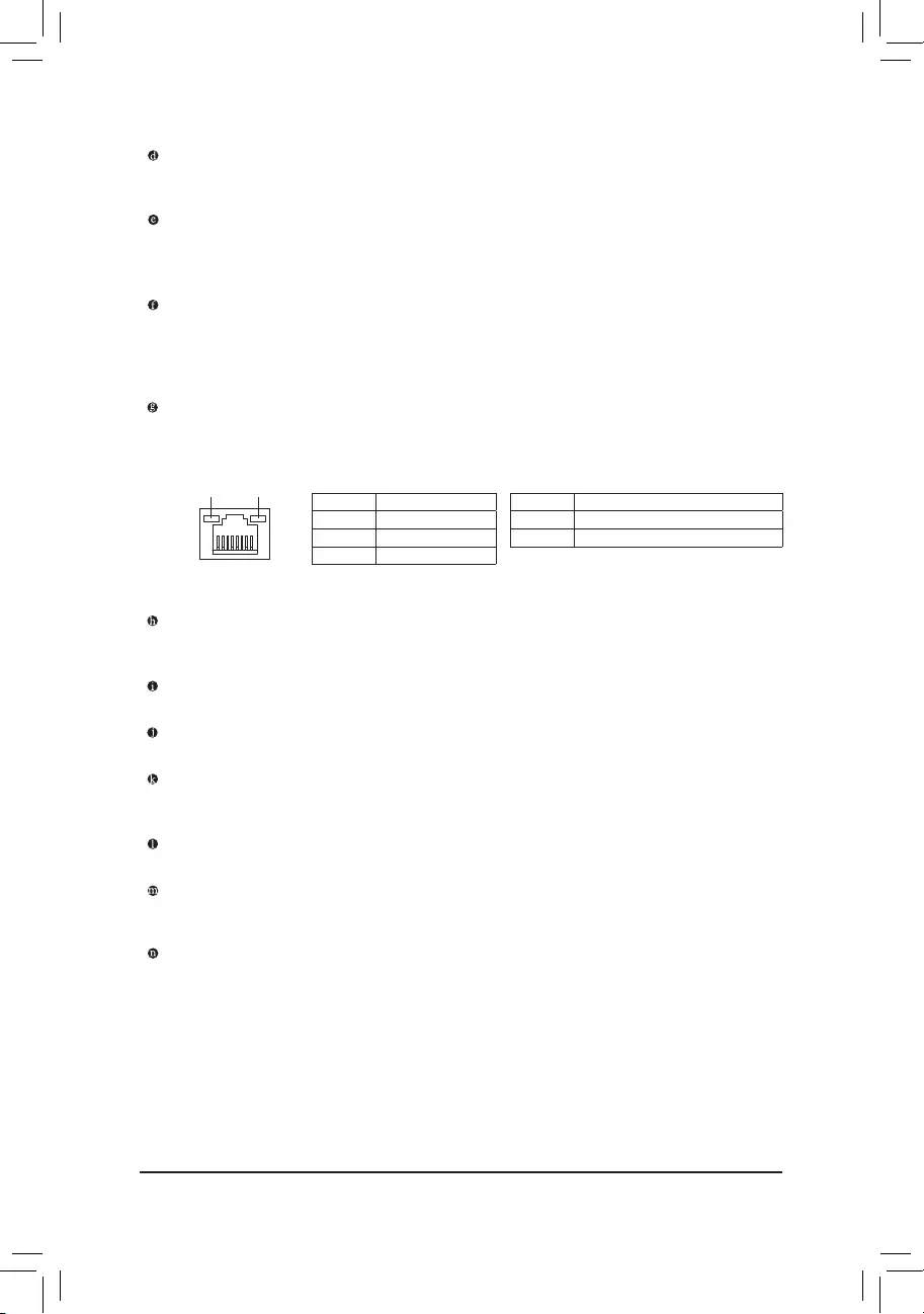
RJ-45 LAN Port
The Gigabit Ethernet LAN port provides Internet connection at up to 2.5 Gbps data rate. The following describes the states of the LAN port LEDs.
|
Connection/ |
Activity LED |
Connection/Speed LED: |
Activity LED: |
|||||||||||
|
Speed LED |
||||||||||||||
|
State |
Description |
State |
Description |
|||||||||||
|
Orange |
2.5 Gbps data rate |
Blinking |
Data transmission or receiving is occurring |
|||||||||||
|
Green |
1 Gbps data rate |
Off |
No data transmission or receiving is occurring |
|||||||||||
|
Off |
100 Mbps data rate |
|||||||||||||
|
LAN Port |
||||||||||||||
USB Type-C™ Port
The reversible USB port supports the USB 3.2 Gen 2 specification and is compatible to the USB 3.2 Gen 1 and USB 2.0 specification. Use this port for USB devices.
Center/Subwoofer Speaker Out
Use this audio jack to connect center/subwoofer speakers.
Rear Speaker Out
Use this audio jack to connect rear speakers.
Optical S/PDIF Out Connector
This connector provides digital audio out to an external audio system that supports digital optical audio. Before using this feature, ensure that your audio system provides an optical digital audio in connector.
Line In/Side Speaker Out
The line in jack. Use this audio jack for line in devices such as an optical drive, walkman, etc.
Line Out/Front Speaker Out
The line out jack. This jack supports audio amplifying function. For better sound quality, it is recommended that you connect your headphone/speaker to this jack (actual effects may vary by the device being used).
Mic In/Side Speaker Out
The Mic in jack.
(Note 1) For new Generation AMD Ryzen™ with Radeon™ Graphics processors only.
(Note 2) To enable the Q-Flash Plus function please visit the «Unique Features» webpage of GIGABYTE’s website.
— 13 —
Audio Jack Configurations:
|
Jack |
Headphone/ |
4-channel |
5.1-channel |
7.1-channel |
|
|
2-channel |
|||||
|
Center/Subwoofer Speaker |
a |
a |
|||
|
Out |
|||||
|
Rear Speaker Out |
a |
a |
a |
||
|
Line In/Side Speaker Out |
a |
||||
|
Line Out/Front Speaker Out |
a |
a |
a |
a |
|
|
Mic In/Side Speaker Out |
a |

 If you want to install a Side Speaker, you need to retask either the Line in or Mic in jack to be Side Speaker out through the audio driver.
Please visit GIGABYTE’s website for details on configuring the audio software.
— 14 —
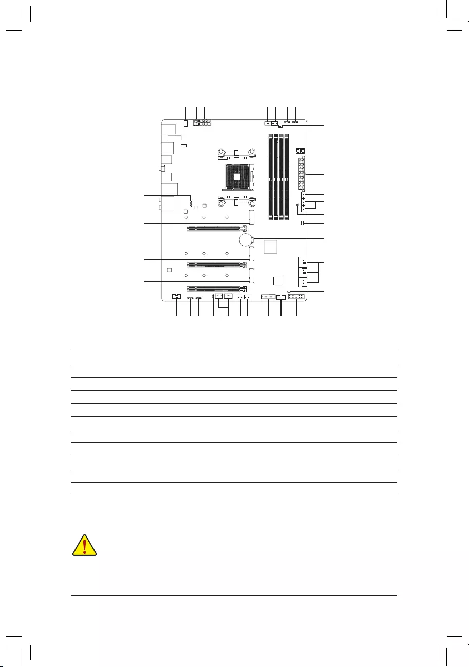
1-7 Internal Connectors
|
4 |
1 |
1 |
6 |
3 |
8 |
10 |
11
|
2 |
|||||||||
|
9 |
5 |
||||||||
|
4 |
|||||||||
|
7 |
|||||||||
|
13 |
21 |
||||||||
|
20 |
|||||||||
|
13 |
12 |
||||||||
|
13 |
|||||||||
|
19 |
|||||||||
|
15 |
8 |
10 |
7 |
17 |
4 |
5 |
16 |
18 |
14 |
|
1) |
ATX_12V1/ATX_12V2 |
12) |
SATA3 0/1/2/3/4/5 |
|
2) |
ATX |
13) |
M2A_CPU/M2B_CPU/M2C_CPU |
|
3) |
CPU_FAN |
14) |
F_PANEL |
|
4) |
SYS_FAN1/2/3/4 |
15) |
F_AUDIO |
|
5) |
SYS_FAN5_PUMP/SYS_FAN6_PUMP |
16) |
F_U32 |
|
6) |
CPU_OPT |
17) |
F_USB1/F_USB2 |
|
7) |
EC_TEMP1/EC_TEMP2 |
18) |
TPM |
|
|
D_LED1/D_LED2 |
19) |
CLR_CMOS |
|
9) |
LED_CPU |
20) |
BAT |
|
10) |
LED_C1/LED_C2 |
21) |
CPU/DRAM/VGA/BOOT |
|
11) |
NOISE_SENSOR |
Read the following guidelines before connecting external devices:
•• First make sure your devices are compliant with the connectors you wish to connect.
•• Before installing the devices, be sure to turn off the devices and your computer. Unplug the power cord from the power outlet to prevent damage to the devices.
•• After installing the device and before turning on the computer, make sure the device cable has been securely attached to the connector on the motherboard.
— 15 —
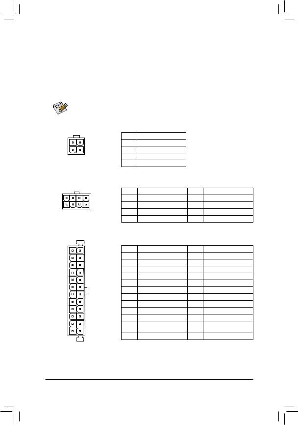
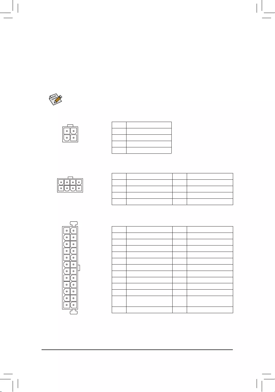
1/2) ATX_12V1/ATX_12V2/ATX (2×2, 2×4, 12V Power Connectors and 2×12 Main Power
Connector)
With the use of the power connector, the power supply can supply enough stable power to all the components on the motherboard. Before connecting the power connector, first make sure the power supply is turned off and all devices are properly installed. The power connector possesses a foolproof design. Connect the power supply cable to the power connector in the correct orientation.
The 12V power connector mainly supplies power to the CPU. If the 12V power connector is not connected, the computer will not start.
To meet expansion requirements, it is recommended that a power supply that can withstand high power consumption be used (500W or greater). If a power supply is used that does not provide the required power, the result can lead to an unstable or unbootable system.
|
ATX_12V1: |
|||||
|
Pin No. |
Definition |
||||
|
3 |
4 |
1 |
GND |
||
|
1 |
2 |
2 |
GND |
||
|
ATX_12V1 |
3 |
+12V |
|||
|
4 |
+12V |
||||
|
ATX_12V2: |
|||||
|
Pin No. |
Definition |
Pin No. |
Definition |
||
|
5 |
8 |
1 |
GND (Only for 2×4-pin 12V) |
5 |
+12V (Only for 2×4-pin 12V) |
|
1 |
4 |
2 |
GND (Only for 2×4-pin 12V) |
6 |
+12V (Only for 2×4-pin 12V) |
|
ATX_12V2 |
3 |
GND |
7 |
+12V |
|
|
4 |
GND |
8 |
+12V |
||
|
ATX: |
|||||
|
12 |
24 |
Pin No. |
Definition |
Pin No. |
Definition |
|
1 |
3.3V |
13 |
3.3V |
||
|
2 |
3.3V |
14 |
-12V |
||
|
3 |
GND |
15 |
GND |
||
|
4 |
+5V |
16 |
PS_ON (soft On/Off) |
||
|
5 |
GND |
17 |
GND |
||
|
6 |
+5V |
18 |
GND |
||
|
7 |
GND |
19 |
GND |
||
|
8 |
Power Good |
20 |
NC |
||
|
9 |
5VSB (stand by +5V) |
21 |
+5V |
||
|
10 |
+12V |
22 |
+5V |
||
|
11 |
+12V (Only for 2×12-pin |
23 |
+5V (Only for 2×12-pin ATX) |
||
|
1 |
13 |
12 |
ATX) |
24 |
GND (Only for 2×12-pin ATX) |
|
3.3V (Only for 2×12-pin ATX) |
ATX
— 16 —
 Loading…

To reduce the impacts on global warming, the packaging materials of this product
are recyclable and reusable. GIGABYTE works with you to protect the environment.
For more product details, please visit GIGABYTE’s website.
B550 AORUS MASTER
User’s Manual
Rev. 1001
12ME-B55AMST-1001R
Copyright
© 2020 GIGA-BYTE TECHNOLOGY CO., LTD. All rights reserved.
The trademarks mentioned in this manual are legally registered to their respective owners.
Disclaimer
Information in this manual is protected by copyright laws and is the property of GIGABYTE.
Changes to the specications and features in this manual may be made by GIGABYTE
without prior notice.
No part of this manual may be reproduced, copied, translated, transmitted, or published in any
form or by any means without GIGABYTE’s prior written permission.
Documentation Classications
In order to assist in the use of this product, GIGABYTE provides the following types of
documentations:
For quick set-up of the product, read the Quick Installation Guide included with the product.
For detailed product information, carefully read the User’s Manual.
For product-related information, check on our website at: https://www.gigabyte.com
Identifying Your Motherboard Revision
The revision number on your motherboard looks like this: «REV: X.X.» For example, «REV:
1.0″ means the revision of the motherboard is 1.0. Check your motherboard revision before
updating motherboard BIOS, drivers, or when looking for technical information.
Example:

— 3 —
Table of Contents
B550 AORUS MASTER Motherboard Layout ………………………………………………………..4
B550 AORUS MASTER Motherboard Block Diagram …………………………………………….. 5
Chapter 1 Hardware Installation ………………………………………………………………………….6
1-1 Installation Precautions ………………………………………………………………………… 6
1-2 Product Specications ………………………………………………………………………….. 7
1-3 Installing the CPU ……………………………………………………………………………… 11
1-4 Installing the Memory …………………………………………………………………………. 11
1-5 Installing an Expansion Card ………………………………………………………………. 12
1-6 Back Panel Connectors ………………………………………………………………………. 12
1-7 Internal Connectors ……………………………………………………………………………. 15
Chapter 2 BIOS Setup ……………………………………………………………………………………..24
2-1 Startup Screen ………………………………………………………………………………….. 24
2-2 The Main Menu …………………………………………………………………………………. 25
2-3 Favorites (F11) ………………………………………………………………………………….. 26
2-4 Tweaker ……………………………………………………………………………………………. 27
2-5 Settings ……………………………………………………………………………………………. 30
2-6 System Info. ……………………………………………………………………………………… 35
2-7 Boot …………………………………………………………………………………………………. 36
2-8 Save & Exit ……………………………………………………………………………………….. 39
Chapter 3 Appendix …………………………………………………………………………………………40
3-1 Conguring a RAID Set ………………………………………………………………………. 40
3-2 Drivers Installation ……………………………………………………………………………… 42
3-3 Debug LED Codes …………………………………………………………………………….. 43
Regulatory Notices ………………………………………………………………………………………. 47
Contact Us …………………………………………………………………………………………………. 52
— 4 —
B550 AORUS MASTER Motherboard Layout
Box Contents
5B550 AORUS MASTER motherboard 5One antenna
5Motherboard driver disc 5Four SATA cables
5User’s Manual 5Two thermistor cables
5Quick Installation Guide 5One noise detection cable
5One RGB LED strip extension cable 5Two Velcro cable ties
5One addressable LED strip adapter cable 5One G Connector
* The box contents above are for reference only and the actual items shall depend on the product package you obtain.
The box contents are subject to change without notice.
CPU DRAM
VGA BOOT
USB 2.0 Hub
USB20
USB_HDMI
U32G2C
U32G2_1
U32G2_2
QFLASH_PLUS
QFLED
U32G2_LAN
ATX
DB_PORT (Note)
AUDIO
DDR4_A1
DDR4_A2
DDR4_B1
DDR4_B2
ATX_12V2
ATX_12V1
AMD B550
CLR_CMOS
M_BIOS
B_BIOS
PCIEX4_1
PCIEX4_2
PCIEX16
SYS_FAN5_PUMPSYS_FAN4
SYS_FAN2
EC_TEMP1
CODEC
B550 AORUS MASTER
F_PANEL
F_USB1EC_TEMP2 SYS_FAN6_PUMP
F_USB2 SYS_FAN3
USB 2.0 Hub
D_LED2
LED_C1
LED_C2
D_LED1
F_AUDIO F_U32
SYS_FAN1
LED_CPU
M2_WIFI
CPU_OPT
iTE®
Super I/O
M2A_CPU
4280110
M2B_CPU
4280110
M2C_CPU
4280110
SATA3
420
531
BAT
Realtek®
2.5GbE LAN
TPM
Socket AM4
CPU_FAN NOISE_
SENSOR
(Note) For debug code information, please refer to Chapter 3.
x1
— 5 —
B550 AORUS MASTER Motherboard Block Diagram
AMD Socket
AM4 CPU
CPU CLK+/- (100~500 MHz)
PCI Express 4.0/3.0 Bus
PCIe 3.0 x4
LAN
RJ45
M.2 WIFI
Module
Realtek®
2.5GbE LAN
4 SATA 6Gb/s
(SATA3 0~3)
PCI Express 3.0 Bus
Center/Subwoofer
Speaker Out
Line Out
MIC
Line In
S/PDIF Out
Rear Speaker Out
CODEC
8 USB 2.0/1.1
2 USB 3.2 Gen 1
2 USB 2.0/1.1
1 USB Type-C™,
USB 3.2 Gen 2
1 USB 3.2 Gen 2
Type A
4 USB 3.2 Gen 2
Type A
AMD B550
x4x4 x1
HDMI
Switch
1 x PCI Express x4
1 x PCI Express x4
2 SATA 6Gb/s
(SATA3 4/5)
or
USB 2.0
Hub
1 M.2 Socket 3
(M2A_CPU)
LPC
Bus
TPM
iTE®
Super I/O
SPI
Bus Dual BIOS
Switch
x16
1 PCI Express x16
1 PCI Express x8
or
2 M.2 Socket 3
(M2B_CPU/
M2C_CPU)
DDR4 3200/2933/2667/2400/2133 MHz

Chapter 1 Hardware Installation
1-1 Installation Precautions
The motherboard contains numerous delicate electronic circuits and components which can become
damaged as a result of electrostatic discharge (ESD). Prior to installation, carefully read the user’s
manual and follow these procedures:
•Prior to installation, make sure the chassis is suitable for the motherboard.
•Prior to installation, do not remove or break motherboard S/N (Serial Number) sticker or
warranty sticker provided by your dealer. These stickers are required for warranty validation.
•Always remove the AC power by unplugging the power cord from the power outlet before
installing or removing the motherboard or other hardware components.
•When connecting hardware components to the internal connectors on the motherboard, make
sure they are connected tightly and securely.
•When handling the motherboard, avoid touching any metal leads or connectors.
•It is best to wear an electrostatic discharge (ESD) wrist strap when handling electronic
components such as a motherboard, CPU or memory. If you do not have an ESD wrist strap,
keep your hands dry and rst touch a metal object to eliminate static electricity.
•Prior to installing the motherboard, please have it on top of an antistatic pad or within an
electrostatic shielding container.
•Before connecting or unplugging the power supply cable from the motherboard, make sure
the power supply has been turned off.
•Before turning on the power, make sure the power supply voltage has been set according to
the local voltage standard.
•Before using the product, please verify that all cables and power connectors of your hardware
components are connected.
•To prevent damage to the motherboard, do not allow screws to come in contact with the
motherboard circuit or its components.
•Make sure there are no leftover screws or metal components placed on the motherboard or
within the computer casing.
•Do not place the computer system on an uneven surface.
•Do not place the computer system in a high-temperature or wet environment.
•Turning on the computer power during the installation process can lead to damage to system
components as well as physical harm to the user.
•If you are uncertain about any installation steps or have a problem related to the use of the
product, please consult a certied computer technician.
•If you use an adapter, extension power cable, or power strip, ensure to consult with its installation
and/or grounding instructions.
— 6 —
1-2 Product Specications
CPU AMD Socket AM4, support for:
3rd Generation AMD Ryzen™ processors/
New Generation AMD Ryzen™ with Radeon™ Graphics processors
(Go to GIGABYTE’s website for the latest CPU support list.)
Chipset AMD B550
Memory 4 x DDR4 DIMM sockets supporting up to 128 GB (32 GB single DIMM capacity)
of system memory
Support for DDR4 3200/2933/2667/2400/2133 MHz memory modules
Dual channel memory architecture
Support for ECC Un-buffered DIMM 1Rx8/2Rx8 memory modules
Support for non-ECC Un-buffered DIMM 1Rx8/2Rx8/1Rx16 memory modules
Support for Extreme Memory Prole (XMP) memory modules
(Go to GIGABYTE’s website for the latest supported memory speeds and memory
modules.)
Onboard
Graphics
Integrated in the New Generation AMD Ryzen™ with Radeon™ Graphics processors:
— 1 x HDMI port, supporting a maximum resolution of 4096×2160@60 Hz
* Support for HDMI 2.1 version, HDCP 2.3, and HDR.
Maximum shared memory of 16 GB
Audio Realtek® ALC1220-VB codec
* The back panel line out jack supports DSD audio.
Support for DTS:X® Ultra
High Denition Audio
2/4/5.1/7.1-channel
Support for S/PDIF Out
LAN Realtek® 2.5GbE LAN chip (2.5 Gbit/1 Gbit/100 Mbit)
Wireless
Communication
Module
Intel® Wi-Fi 6 AX200
— WIFI a, b, g, n, ac with wave 2 features, ax, supporting 2.4/5 GHz Dual-Band
— BLUETOOTH 5
— Support for 11ax 160MHz wireless standard and up to 2.4 Gbps data rate
* Actual data rate may vary depending on environment and equipment.
Expansion Slots 1 x PCI Express x16 slot (PCIEX16), integrated in the CPU:
— 3rd Generation AMD Ryzen™ processors support PCIe 4.0 x16 mode
— New Generation AMD Ryzen™ with Radeon™ Graphics processors support
PCIe 3.0 x16 mode
* For optimum performance, if only one PCI Express graphics card is to be installed,
be sure to install it in the PCIEX16 slot.
* The PCIEX16 slot shares bandwidth with the M2B_CPU and M2C_CPU connectors.
The PCIEX16 slot operates at up to x8 mode when a device is installed in the
M2B_CPU or M2C_CPU connector.
2 x PCI Express x16 slots (PCIEX4_1/PCIEX4_2), integrated in the Chipset:
— Supporting PCIe 3.0 x4 mode
* The PCIEX4_2 slot shares bandwidth with the SATA3 4, 5 connectors. The PCIEX4_2
slot operates at up to x2 mode when a device is installed in the SATA3 4 or SATA3 5
connector.
— 7 —
Storage Interface 1 x M.2 connector (M2A_CPU), integrated in the CPU, supporting Socket 3,
M key, type 2242/2280/22110 SSDs:
— 3rd Generation AMD Ryzen™ processors support SATA and PCIe 4.0 x4/x2
SSDs
— New Generation AMD Ryzen™ with Radeon™ Graphics processors support
SATA and PCIe 3.0 x4/x2 SSDs
2 x M.2 connectors (M2B_CPU/M2C_CPU), integrated in the CPU, supporting
Socket 3, M key, type 2242/2280/22110 SSDs:
— 3rd Generation AMD Ryzen™ processors support PCIe 4.0 x4/x2 SSDs
— New Generation AMD Ryzen™ with Radeon™ Graphics processors support
PCIe 3.0 x4/x2 SSDs
6 x SATA 6Gb/s connectors, integrated in the Chipset:
— Support for RAID 0, RAID 1, and RAID 10
USB CPU:
— 4 x USB 3.2 Gen 2 Type-A ports (red) on the back panel
Chipset:
— 1 x USB Type-C™ port on the back panel, with USB 3.2 Gen 2 support
— 1 x USB 3.2 Gen 2 Type-A port (red) on the back panel
— 2 x USB 3.2 Gen 1 ports available through the internal USB header
— 2 x USB 2.0/1.1 ports on the back panel
Chipset+2 USB 2.0 Hubs:
— 8 x USB 2.0/1.1 ports (4 ports on the back panel, 4 ports available through
the internal USB headers)
Internal
Connectors
1 x 24-pin ATX main power connector
1 x 8-pin ATX 12V power connector
1 x 4-pin ATX 12V power connector
1 x CPU fan header
1 x water cooling CPU fan header
4 x system fan headers
2 x system fan/water cooling pump headers
2 x addressable LED strip headers
2 x RGB LED strip headers
1 x CPU cooler LED strip/RGB LED strip header
3 x M.2 Socket 3 connectors
6 x SATA 6Gb/s connectors
1 x front panel header
1 x front panel audio header
1 x USB 3.2 Gen 1 header
2 x USB 2.0/1.1 headers
1 x noise detection header
1 x Trusted Platform Module (TPM) header (2×6 pin, for the GC-TPM2.0_S
module only)
1 x Clear CMOS jumper
2 x temperature sensor headers
— 8 —
Back Panel
Connectors
2 x SMA antenna connectors (2T2R)
1 x HDMI port
6 x USB 2.0/1.1 ports
5 x USB 3.2 Gen 2 Type-A ports (red)
1 x USB Type-C™ port, with USB 3.2 Gen 2 support
1 x Q-Flash Plus button
1 x RJ-45 port
1 x optical S/PDIF Out connector
5 x audio jacks
I/O Controller iTE® I/O Controller Chip
Hardware
Monitor
Voltage detection
Temperature detection
Fan speed detection
Water cooling ow rate detection
Overheating warning
Fan fail warning
Fan speed control
* Whether the fan (pump) speed control function is supported will depend on the fan
(pump) you install.
Noise detection
BIOS 2 x 256 Mbit ash
Use of licensed AMI UEFI BIOS
Support for DualBIOS™
PnP 1.0a, DMI 2.7, WfM 2.0, SM BIOS 2.7, ACPI 5.0
Unique Features Support for APP Center
* Available applications in APP Center may vary by motherboard model. Supported
functions of each application may also vary depending on motherboard specications.
— @BIOS
— EasyTune
— Fast Boot
— Game Boost
— ON/OFF Charge
— RGB Fusion
— Smart Backup
— System Information Viewer
Support for Q-Flash Plus
Support for Q-Flash
Support for Xpress Install
— 9 —
Bundled
Software
Norton® Internet Security (OEM version)
XSplit Gamecaster + Broadcaster (12 months license)
Realtek® 8125 Gaming LAN Bandwidth Control Utility
Operating
System Support for Windows 10 64-bit
Form Factor ATX Form Factor; 30.5cm x 24.4cm
* GIGABYTE reserves the right to make any changes to the product specications and product-related information without
prior notice.
Please visit GIGABYTE’s website
for support lists of CPU, memory
modules, SSDs, and M.2 devices.
Please visit the SupportUtility List
page on GIGABYTE’s website to
download the latest version of apps.
— 10 —
Please visit GIGABYTE’s website for details on hardware installation.
Dual Channel Memory Conguration
This motherboard provides four memory sockets and supports Dual Channel Technology. After the memory
is installed, the BIOS will automatically detect the specications and capacity of the memory. Enabling Dual
Channel memory mode will double the original memory bandwidth.
The four memory sockets are divided into two channels and each channel has two memory sockets as following:
Channel A: DDR4_A1, DDR4_A2
Channel B: DDR4_B1, DDR4_B2
1-3 Installing the CPU
Read the following guidelines before you begin to install the CPU:
•Make sure that the motherboard supports the CPU.
(Go to GIGABYTE’s website for the latest CPU support list.)
•Always turn off the computer and unplug the power cord from the power outlet before installing the
CPU to prevent hardware damage.
•Locate the pin one of the CPU. The CPU cannot be inserted if oriented incorrectly.
•Apply an even and thin layer of thermal grease on the surface of the CPU.
•Do not turn on the computer if the CPU cooler is not installed, otherwise overheating and damage
of the CPU may occur.
•Set the CPU host frequency in accordance with the CPU specications. It is not recommended
that the system bus frequency be set beyond hardware specications since it does not meet the
standard requirements for the peripherals. If you wish to set the frequency beyond the standard
specications, please do so according to your hardware specications including the CPU, graphics
card, memory, hard drive, etc.
Installing the CPU
Locate the pin one (denoted by a small triangle) of the CPU socket and the CPU.
AM4 Socket
A Small Triangle
Marking Denotes Pin
One of the Socket AM4 CPU
A Small Triangle
Marking Denotes CPU
Pin One
1-4 Installing the Memory
Read the following guidelines before you begin to install the memory:
•Make sure that the motherboard supports the memory. It is recommended that memory of the same
capacity, brand, speed, and chips be used.
(Go to GIGABYTE’s website for the latest supported memory speeds and memory modules.)
•Always turn off the computer and unplug the power cord from the power outlet before installing the
memory to prevent hardware damage.
•Memory modules have a foolproof design. A memory module can be installed in only one direction.
If you are unable to insert the memory, switch the direction.
— 11 —
Due to CPU limitations, read the following guidelines before installing the memory in Dual Channel mode.
1. Dual Channel mode cannot be enabled if only one memory module is installed.
2. When enabling Dual Channel mode with two or four memory modules, it is recommended that memory
of the same capacity, brand, speed, and chips be used.
1-5 Installing an Expansion Card
Read the following guidelines before you begin to install an expansion card:
•Make sure the motherboard supports the expansion card. Carefully read the manual that came
with your expansion card.
•Always turn off the computer and unplug the power cord from the power outlet before installing an
expansion card to prevent hardware damage.
Recommanded Dual Channel Memory Conguration:
DDR4_A1 DDR4_A2 DDR4_B1 DDR4_B2
2 Modules — — DS/SS — — DS/SS
4 Modules DS/SS DS/SS DS/SS DS/SS
(SS=Single-Sided, DS=Double-Sided, «- -«=No Memory)
1-6 Back Panel Connectors
USB 2.0/1.1 Port
The USB port supports the USB 2.0/1.1 specication. Use this port for USB devices.
SMA Antenna Connectors (2T2R)
Use this connector to connect an antenna.
HDMI Port (Note 1)
The HDMI port is HDCP 2.3 compliant and supports Dolby TrueHD and DTS HD
Master Audio formats. It also supports up to 192KHz/24bit 7.1-channel LPCM
audio output. You can use this port to connect your HDMI-supported monitor. The maximum supported
resolution is 4096×2160@60 Hz, but the actual resolutions supported are dependent on the monitor being
used.
After installing the HDMI device, make sure to set the default sound playback device to HDMI.
(The item name may differ depending on your operating system.)
Tighten the antennas to the antenna connectors and then aim the antennas correctly for better
signal reception.
•When removing the cable connected to a back panel connector, rst remove the cable from your
device and then remove it from the motherboard.
•When removing the cable, pull it straight out from the connector. Do not rock it side to side to
prevent an electrical short inside the cable connector.
— 12 —
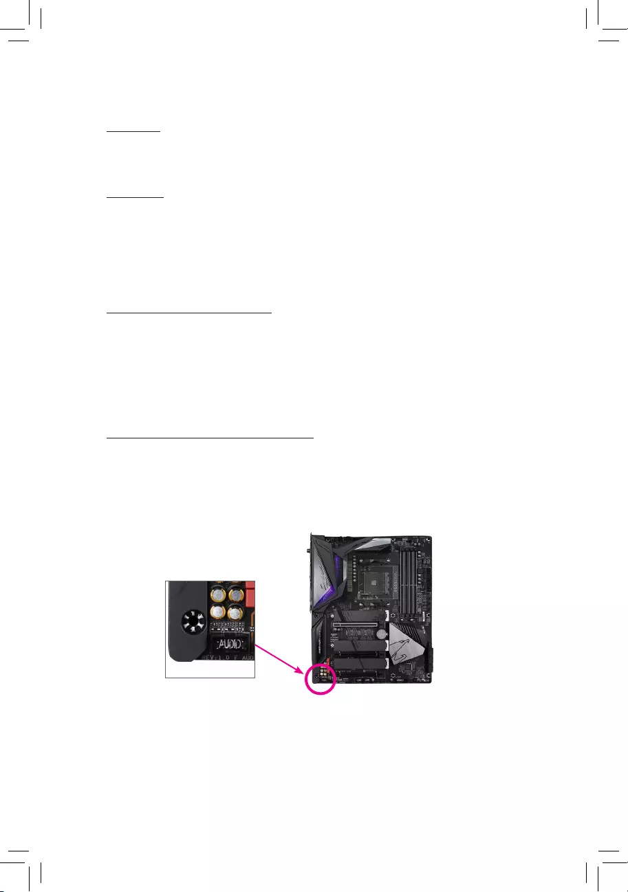
USB 3.2 Gen 2 Port
The USB 3.2 Gen 2 port supports the USB 3.2 Gen 2 specication and is compatible to the USB 3.2 Gen 1
and USB 2.0 specication. Use this port for USB devices.
USB 3.2 Gen 2 Port (Q-Flash Plus Port)
The USB 3.2 Gen 2 port supports the USB 3.2 Gen 2 specication and is compatible to the USB 3.2 Gen 1
and USB 2.0 specication. Use this port for USB devices. Before using Q-Flash Plus (Note 2), make sure to
insert the USB ash drive into this port rst.
Q-Flash Plus Button (Note 2)
Q-Flash Plus allows you to update the BIOS when your system is off (S5 shutdown state). Save the latest
BIOS on a USB thumb drive and plug it into the Q-Flash Plus port, and then you can now ash the BIOS
automatically by simply pressing the Q-Flash Plus button. The QFLED will ash when the BIOS matching
and ashing activities start and will stop ashing when the main BIOS ashing is complete.
RJ-45 LAN Port
The Gigabit Ethernet LAN port provides Internet connection at up to 2.5 Gbps data rate. The following
describes the states of the LAN port LEDs.
USB Type-C™ Port
The reversible USB port supports the USB 3.2 Gen 2 specication and is compatible to the USB 3.2 Gen 1
and USB 2.0 specication. Use this port for USB devices.
Center/Subwoofer Speaker Out
Use this audio jack to connect center/subwoofer speakers.
Rear Speaker Out
Use this audio jack to connect rear speakers.
Optical S/PDIF Out Connector
This connector provides digital audio out to an external audio system that supports digital optical audio.
Before using this feature, ensure that your audio system provides an optical digital audio in connector.
Line In/Side Speaker Out
The line in jack. Use this audio jack for line in devices such as an optical drive, walkman, etc.
Line Out/Front Speaker Out
The line out jack. This jack supports audio amplifying function. For better sound quality, it is recommended
that you connect your headphone/speaker to this jack (actual effects may vary by the device being used).
Mic In/Side Speaker Out
The Mic in jack.
(Note 1) For new Generation AMD Ryzen™ with Radeon™ Graphics processors only.
(Note 2) To enable the Q-Flash Plus function please visit the «Unique Features» webpage of GIGABYTE’s
website.
Connection/
Speed LED Activity LED
LAN Port
Connection/Speed LED:
State Description
Orange 2.5 Gbps data rate
Green 1 Gbps data rate
Off 100 Mbps data rate
Activity LED:
State Description
Blinking Data transmission or receiving is occurring
Off No data transmission or receiving is occurring
— 13 —
Please visit GIGABYTE’s website for details on conguring the audio software.
If you want to install a Side Speaker, you need to retask either the Line in or Mic in jack to be
Side Speaker out through the audio driver.
Audio Jack Congurations:
Jack Headphone/
2-channel 4-channel 5.1-channel 7.1-channel
Center/Subwoofer Speaker
Out a a
Rear Speaker Out a a a
Line In/Side Speaker Out a
Line Out/Front Speaker Out a a a a
Mic In/Side Speaker Out a
— 14 —
1-7 Internal Connectors
Read the following guidelines before connecting external devices:
•First make sure your devices are compliant with the connectors you wish to connect.
•Before installing the devices, be sure to turn off the devices and your computer. Unplug the power
cord from the power outlet to prevent damage to the devices.
•After installing the device and before turning on the computer, make sure the device cable has
been securely attached to the connector on the motherboard.
1) ATX_12V1/ATX_12V2
2) ATX
3) CPU_FAN
4) SYS_FAN1/2/3/4
5) SYS_FAN5_PUMP/SYS_FAN6_PUMP
6) CPU_OPT
7) EC_TEMP1/EC_TEMP2
 D_LED1/D_LED2
9) LED_CPU
10) LED_C1/LED_C2
11) NOISE_SENSOR
12) SATA3 0/1/2/3/4/5
13) M2A_CPU/M2B_CPU/M2C_CPU
14) F_PANEL
15) F_ AUDIO
16) F_U32
17) F_USB1/F_USB2
18) TPM
19) CLR_CMOS
20) BAT
21) CPU/DRAM/VGA/BOOT
1454
21
20
2
11
7
12
5
4
17 1816815
1 1
4
710
19
13
13
9
13
3 8 106
— 15 —
131
2412
ATX
1/2) ATX_12V1/ATX_12V2/ATX (2×2, 2×4, 12V Power Connectors and 2×12 Main Power
Connector)
With the use of the power connector, the power supply can supply enough stable power to all the components
on the motherboard. Before connecting the power connector, rst make sure the power supply is turned
off and all devices are properly installed. The power connector possesses a foolproof design. Connect the
power supply cable to the power connector in the correct orientation.
The 12V power connector mainly supplies power to the CPU. If the 12V power connector is not connected,
the computer will not start.
To meet expansion requirements, it is recommended that a power supply that can withstand high
power consumption be used (500W or greater). If a power supply is used that does not provide the
required power, the result can lead to an unstable or unbootable system.
ATX:
Pin No. Denition Pin No. Denition
1 3.3V 13 3.3V
2 3.3V 14 -12V
3 GND 15 GND
4 +5V 16 PS_ON (soft On/Off)
5 GND 17 GND
6 +5V 18 GND
7 GND 19 GND
8 Power Good 20 NC
9 5VSB (stand by +5V) 21 +5V
10 +12V 22 +5V
11 +12V (Only for 2×12-pin
ATX)
23 +5V (Only for 2×12-pin ATX)
12 3.3V (Only for 2×12-pin ATX) 24 GND (Only for 2×12-pin ATX)
ATX_12V2:
Pin No. Denition Pin No. Denition
1 GND (Only for 2×4-pin 12V) 5 +12V (Only for 2×4-pin 12V)
2 GND (Only for 2×4-pin 12V) 6 +12V (Only for 2×4-pin 12V)
3 GND 7 +12V
4 GND 8 +12V
ATX_12V2
41
85
ATX_12V1:
Pin No. Denition
1 GND
2 GND
3 +12V
4 +12V
ATX_12V1
1
3
2
4
— 16 —
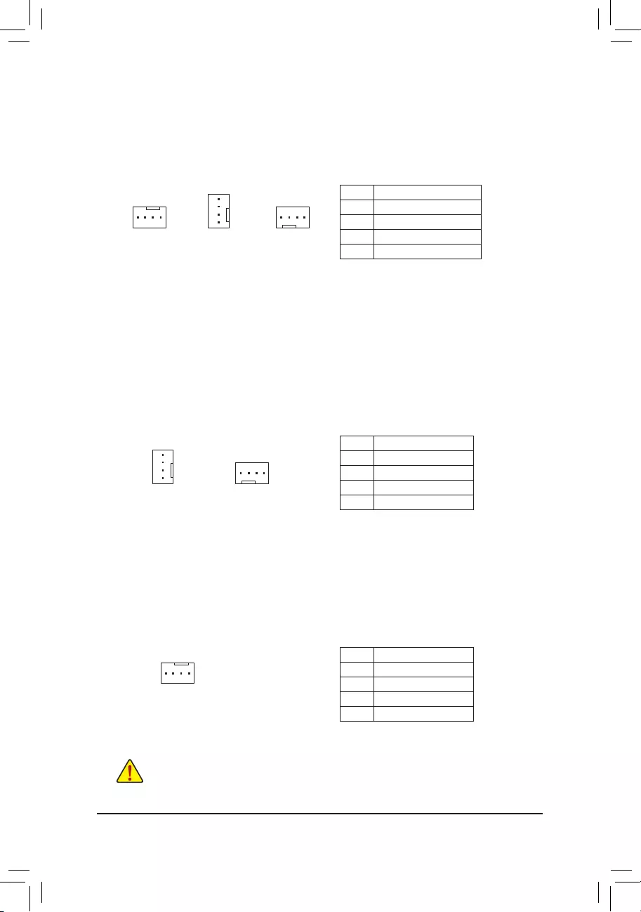
5) SYS_FAN5_PUMP/SYS_FAN6_PUMP (System Fan/Water Cooling Pump Headers)
The fan/pump headers are 4-pin. Most fan headers possess a foolproof insertion design. When connecting
a fan cable, be sure to connect it in the correct orientation (the black connector wire is the ground wire). The
speed control function requires the use of a fan with fan speed control design. For optimum heat dissipation,
it is recommended that a system fan be installed inside the chassis. The header also provides speed control
for a water cooling pump, refer to Chapter 2, «BIOS Setup,» «SettingsSmart Fan 5,» for more information.
6) CPU_OPT (Water Cooling CPU Fan Header)
The fan header is 4-pin and possesses a foolproof insertion design. Most fan headers possess a foolproof
insertion design. When connecting a fan cable, be sure to connect it in the correct orientation (the black
connector wire is the ground wire). The speed control function requires the use of a fan with fan speed control
design.
1
Pin No. Denition
1 GND
2 Voltage Speed Control
3 Sense
4 PWM Speed Control
Pin No. Denition
1 GND
2 Voltage Speed Control
3 Sense
4 PWM Speed Control
3/4) CPU_FAN/SYS_FAN1/2/3/4 (Fan Headers)
All fan headers on this motherboard are 4-pin. Most fan headers possess a foolproof insertion design.
When connecting a fan cable, be sure to connect it in the correct orientation (the black connector wire is
the ground wire). The speed control function requires the use of a fan with fan speed control design. For
optimum heat dissipation, it is recommended that a system fan be installed inside the chassis.
•Be sure to connect fan cables to the fan headers to prevent your CPU and system from
overheating. Overheating may result in damage to the CPU or the system may hang.
•These fan headers are not conguration jumper blocks. Do not place a jumper cap on the headers.
CPU_FAN SYS_FAN3SYS_FAN1/SYS_FAN2/
SYS_FAN4
1
1
SYS_FAN6_PUMP
1
1
SYS_FAN5_PUMP
1
Pin No. Denition
1 GND
2 Voltage Speed Control
3 Sense
4 PWM Speed Control
— 17 —
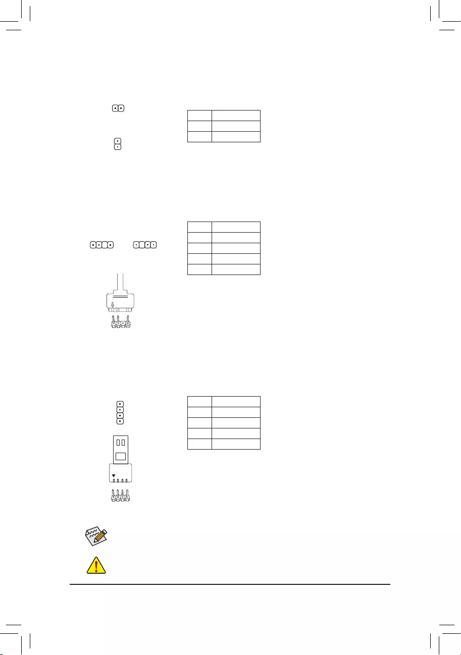
D_LED1/D_LED2 (Addressable LED Strip Headers)
The headers can be used to connect a standard 5050 addressable LED strip, with maximum power rating
of 5A (5V) and maximum number of 1000 LEDs.
Pin No. Denition
1 V (5V)
2 Data
3 No Pin
4 GND
Connect one end of the included addressable LED strip adapter cable
to this header and the other end to your addressable LED strip. The
power pin (marked with a triangle on the plug) of the LED strip must
be connected to Pin 1 of the addressable LED strip header. Incorrect
connection may lead to the damage of the LED strip.
7) EC_TEMP1/EC_TEMP2 (Temperature Sensor Headers)
Connect the thermistor cables to the headers for temperature detection.
Pin No. Denition
1 SENSOR IN
2 GND
1
1
EC_TEMP1
EC_TEMP2
Before installing the devices, be sure to turn off the devices and your computer. Unplug the power
cord from the power outlet to prevent damage to the devices.
9) LED_CPU (CPU Cooler LED Strip/RGB LED Strip Header)
The header can be used to connect a CPU cooler LED strip or a standard 5050 RGB LED strip (12V/G/R/B),
with maximum power rating of 2A (12V) and maximum length of 2m.
Pin No. Denition
1 12V
2 G
3 R
4 B
Connect the CPU cooler LED strip/RGB LED strip to the header. The
power pin (marked with a triangle on the plug) of the LED strip must
be connected to Pin 1 (12V) of this header. Incorrect connection may
lead to the damage of the LED strip.
For how to turn on/off the lights of the LED strip please visit the «Unique Features» webpage of
GIGABYTE’s website.
RGB LED
Strip
1
12V
1
1 1
F_USB30 F_U
B_
F_ F_
_
B
BS_
B
SB_
B
_S
S_
_
B
_U
_
B
S
123
123
123
123
1
1
1
1
BSS
S
_S
SSU
1 2 3 4 5
S3 BSSS
U
__ 3
F_USB3F
S _
S _
S _
SF
B_
B_
F
_0
S
S
_0F
_F
_
_
__B
U
S _S
_ SF_
B
USB0_B
B_
B_
F_USB3
F_USB303
_
_3U
S_
F_USB30 F_U
B_
F_ F_
_
B
BS_
B
SB_
B
_S
S_
_
B
_U
_
B
S
123
123
123
123
1
1
1
1
BSS
S
_S
SSU
1 2 3 4 5
S3 BSSS
U
__ 3
F_USB3F
S _
S _
S _
SF
B_
B_
F
_0
S
S
_0F
_F
_
_
__B
U
S _S
_ SF_
B
USB0_B
B_
B_
F_USB3
F_USB303
_
_3U
S_
D_LED1 D_LED2
Addressable LED
Strip Adapter Cable
1
— 18 —
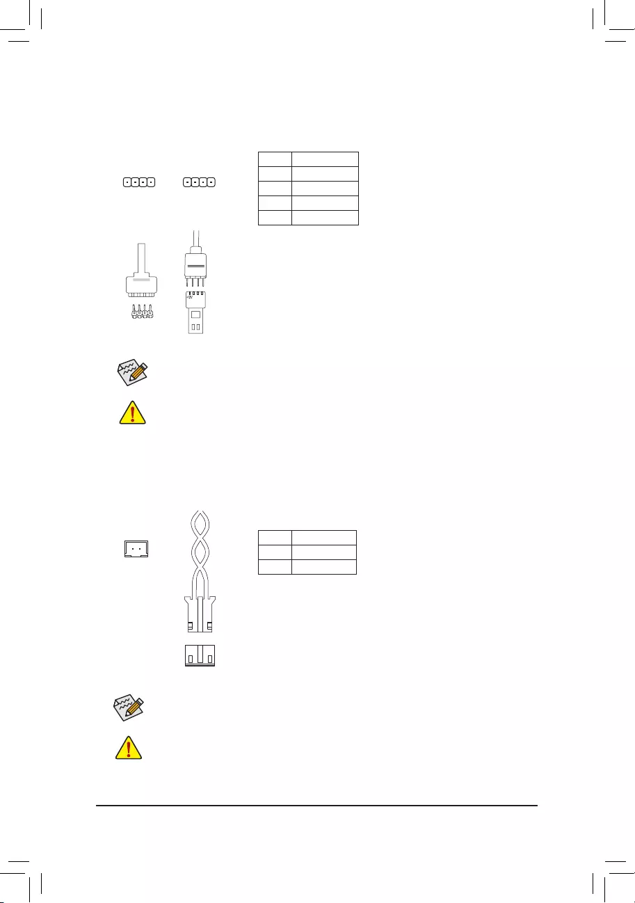
Before installing the devices, be sure to turn off the devices and your computer. Unplug the power
cord from the power outlet to prevent damage to the devices.
10) LED_C1/LED_C2 (RGB LED Strip Headers)
The headers can be used to connect a standard 5050 RGB LED strip (12V/G/R/B), with maximum power
rating of 2A (12V) and maximum length of 2m.
Pin No. Denition
1 12V
2 G
3 R
4 B
1
Connect one end of the RGB LED strip extension cable to the header
and the other end to your RGB LED strip. The black wire (marked with
a triangle on the plug) of the extension cable must be connected to
Pin 1 (12V) of this header. The 12V pin (marked with an arrow) on the
other end of the extension cable must be lined up with the 12V of the
LED strip. Be careful with the connection orientation of the LED strip;
incorrect connection may lead to the damage of the LED strip.
For how to turn on/off the lights of the LED strip please visit the «Unique Features» webpage of
GIGABYTE’s website.
LED_C2
1
LED_C1
12VRGB
12V
1
RGB LED
Strip
BG12VR
11) NOISE_SENSOR (Noise Detection Header)
This header can be used to connect a noise detection cable to detect the noise inside the case.
Pin No. Denition
1 Noise Detection
2 GND
Before connecting the cable to the header, make sure to remove the jumper cap; re-place the
jumper cap if the header is not in use.
For more information on the noise detection function, please visit the «Unique Features» webpage
of GIGABYTE’s website.
1
Noise Detection
Cable
1
— 19 —
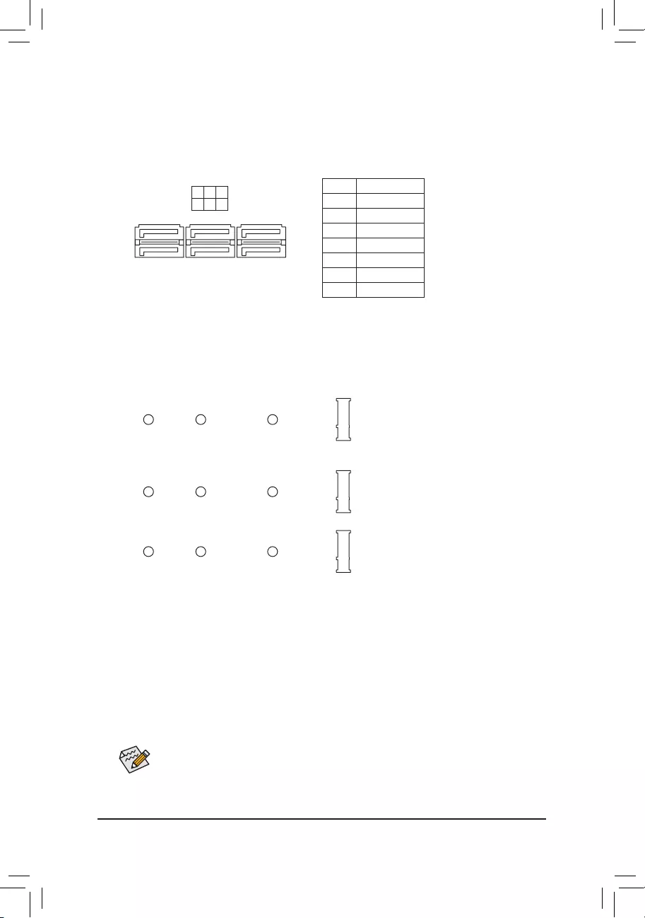
13) M2A_CPU/M2B_CPU/M2C_CPU (M.2 Socket 3 Connectors)
The M.2 connectors support M.2 SATA SSDs or M.2 PCIe SSDs and support RAID conguration. Please
note that an M.2 PCIe SSD cannot be used to create a RAID set either with an M.2 SATA SSD or a SATA
hard drive. Refer to Chapter 3, «Conguring a RAID Set,» for instructions on conguring a RAID array.
Follow the steps below to correctly install an M.2 SSD in the M.2 connector.
Step 1:
Locate the M.2 connector where you will install the M.2 SSD, use a screwdriver to unfasten the screw on
the heatsink and then remove the heatsink. Remove the protective lm from the thermal pad on the M.2
connector.
Step 2:
Locate the proper mounting hole based on the length of your M.2 SSD drive. If needed, move the standoff
to the desired mounting hole. Insert the M.2 SSD into the M.2 connector at an angle.
Step 3:
Press the M.2 SSD down and then secure it with the screw. Replace the heatsink and secure it to the original
hole. Make sure to remove the protective lm from the bottom of the heatsink before replacing the heatsink.
Select the proper hole for the M.2 SSD to be installed and refasten the screw and standoff.
12) SATA3 0/1/2/3/4/5 (SATA 6Gb/s Connectors)
The SATA connectors conform to SATA 6Gb/s standard and are compatible with SATA 3Gb/s and SATA
1.5Gb/s standard. Each SATA connector supports a single SATA device. The SATA connectors support
RAID 0, RAID 1, and RAID 10. Refer to Chapter 3, «Conguring a RAID Set,» for instructions on conguring
a RAID array.
Pin No. Denition
1 GND
2 TXP
3 TXN
4 GND
5 RXN
6 RXP
7 GND
1
1
SATA3 4 2 0
5 3 1
7
7
F_USB30 F_U
B_
F_ F_
_
B
BS_
B
SB_
B
_S
S_
_
B
_U
_
B
S
123
123
123
123
1
1
1
1
BSS
S
_S
SSU
1 2 3 4 5
S3 BSSS
U
__ 3
F_USB3F
S _
S _
S _
SF
B_
B_
F
_0
S
S
_0F
_F
_
_
__B
U
S _S
_ SF_
B
USB0_B
B_
B_
F_USB3
F_USB303
_
_3U
S_
80110 60 42
M2A_CPU
F_USB30 F_U
B_
F_ F_
_
B
BS_
B
SB_
B
_S
S_
_
B
_U
_
B
S
123
123
123
123
1
1
1
1
BSS
S
_S
SSU
1 2 3 4 5
S3 BSSS
U
__ 3
F_USB3F
S _
S _
S _
SF
B_
B_
F
_0
S
S
_0F
_F
_
_
__B
U
S _S
_ SF_
B
USB0_B
B_
B_
F_USB3
F_USB303
_
_3U
S_
80110 60 42
M2B_CPU (Note)
F_USB30 F_U
B_
F_ F_
_
B
BS_
B
SB_
B
_S
S_
_
B
_U
_
B
S
123
123
123
123
1
1
1
1
BSS
S
_S
SSU
1 2 3 4 5
S3 BSSS
U
__ 3
F_USB3F
S _
S _
S _
SF
B_
B_
F
_0
S
S
_0F
_F
_
_
__B
U
S _S
_ SF_
B
USB0_B
B_
B_
F_USB3
F_USB303
_
_3U
S_
80110 60 42
M2C_CPU (Note)
(Note) The PCIEX16 slot shares bandwidth with the M2B_CPU and M2C_CPU connectors. The PCIEX16
slot operates at up to x8 mode when a device is installed in the M2B_CPU or M2C_CPU connector.
— 20 —
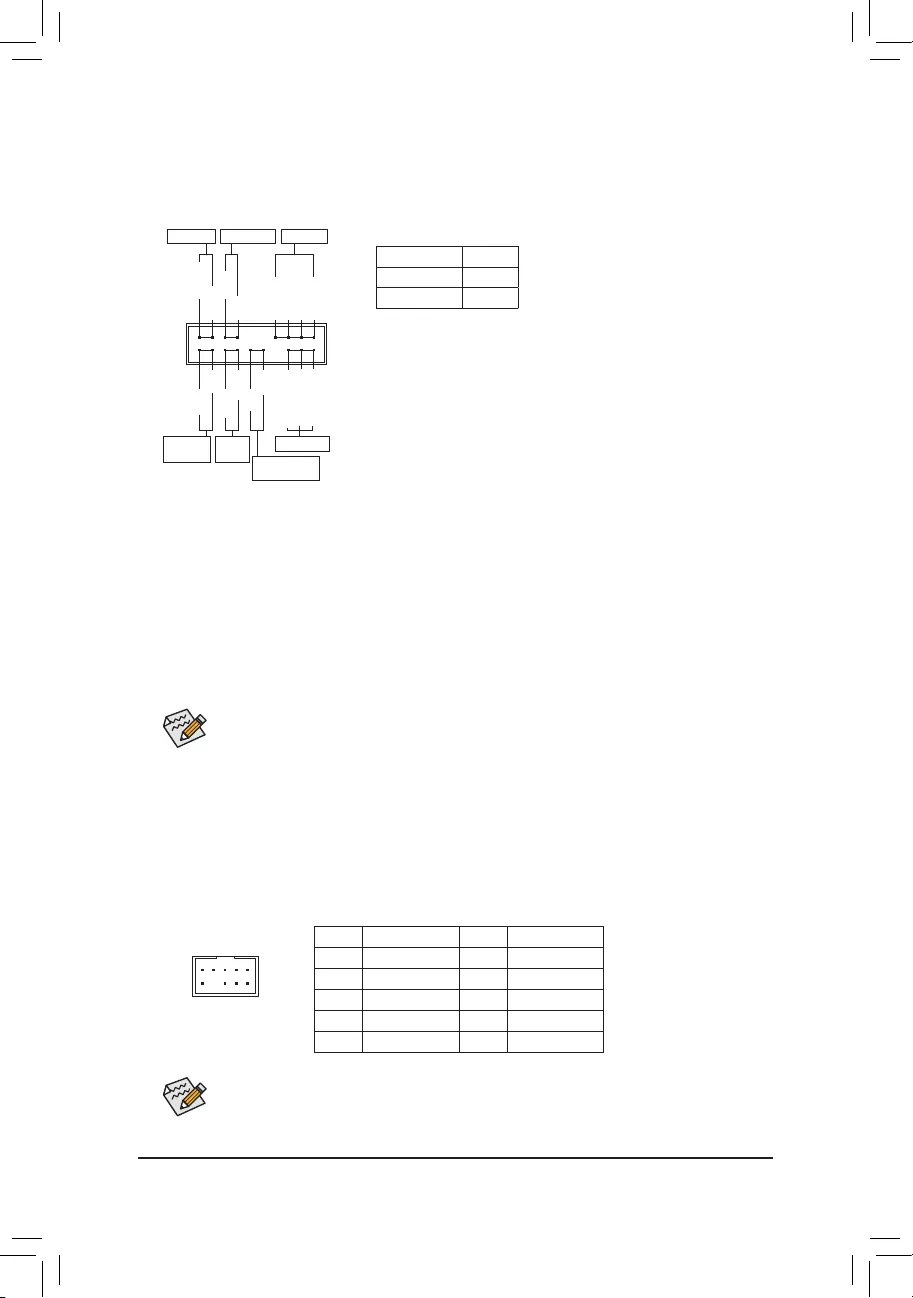
Some chassis provide a front panel audio module that has separated connectors on each wire
instead of a single plug. For information about connecting the front panel audio module that has
different wire assignments, please contact the chassis manufacturer.
14) F_PANEL (Front Panel Header)
Connect the power switch, reset switch, speaker, chassis intrusion switch/sensor and system status indicator
on the chassis to this header according to the pin assignments below. Note the positive and negative pins
before connecting the cables.
15) F_AUDIO (Front Panel Audio Header)
The front panel audio header supports High Denition audio (HD). You may connect your chassis front
panel audio module to this header. Make sure the wire assignments of the module connector match the
pin assignments of the motherboard header. Incorrect connection between the module connector and the
motherboard header will make the device unable to work or even damage it.
F_USB30 F_U
B_
F_ F_
_
B
BS_
B
SB_
B
_S
S_
_
B
_U
_
B
S
123
123
123
123
1
1
1
1
BSS
S
_S
SSU
1 2 3 4 5
S3 BSSS
U
__ 3
F_USB3F
S _
S _
S _
SF
B_
B_
F
_0
S
S
_0F
_F
_
_
__B
U
S _S
_ SF_
B
USB0_B
B_
B_
F_USB3
F_USB303
_
_3U
S_
91
10 2
Pin No. Denition Pin No. Denition
1 MIC2_L 6 Sense
2 GND 7 FAUDIO_JD
3 MIC2_R 8 No Pin
4 NC 9 LINE2_L
5 LINE2_R 10 Sense
The front panel design may differ by chassis. A front panel module mainly consists of power switch,
reset switch, power LED, hard drive activity LED, speaker and etc. When connecting your chassis
front panel module to this header, make sure the wire assignments and the pin assignments are
matched correctly.
System Status LED
S0 On
S3/S4/S5 Off
•PW (Power Switch):
Connects to the power switch on the chassis front panel. You may
congure the way to turn off your system using the power switch
(refer to Chapter 2, «BIOS Setup,» «SettingsPlatform Power,» for more
information).
•SPEAK (Speaker):
Connects to the speaker on the chassis front panel. The system reports
system startup status by issuing a beep code. One single short beep
will be heard if no problem is detected at system startup.
•PLED/PWR_LED (Power LED):
Connects to the power status indicator
on the chassis front panel. The LED is on
when the system is operating. The LED is
off when the system is in S3/S4 sleep state
or powered off (S5).
•HD (Hard Drive Activity LED):
Connects to the hard drive activity LED on the chassis front panel. The LED is on when the hard drive
is reading or writing data.
•RES (Reset Switch):
Connects to the reset switch on the chassis front panel. Press the reset switch to restart the computer
if the computer freezes and fails to perform a normal restart.
•CI (Chassis Intrusion Header):
Connects to the chassis intrusion switch/sensor on the chassis that can detect if the chassis cover has
been removed. This function requires a chassis with a chassis intrusion switch/sensor.
•NC: No connection.
NC
NC
Power LED
1
2
19
20
CI-
CI+
PWR_LED-
PWR_LED+
PLED-
PW-
SPEAK+
SPEAK-
PLED+
PW+
Power LED
HD-
RES+
HD+
RES-
Hard Drive
Activity LED
Reset
Switch Chassis Intrusion
Header
Power Switch Speaker
PWR_LED-
— 21 —
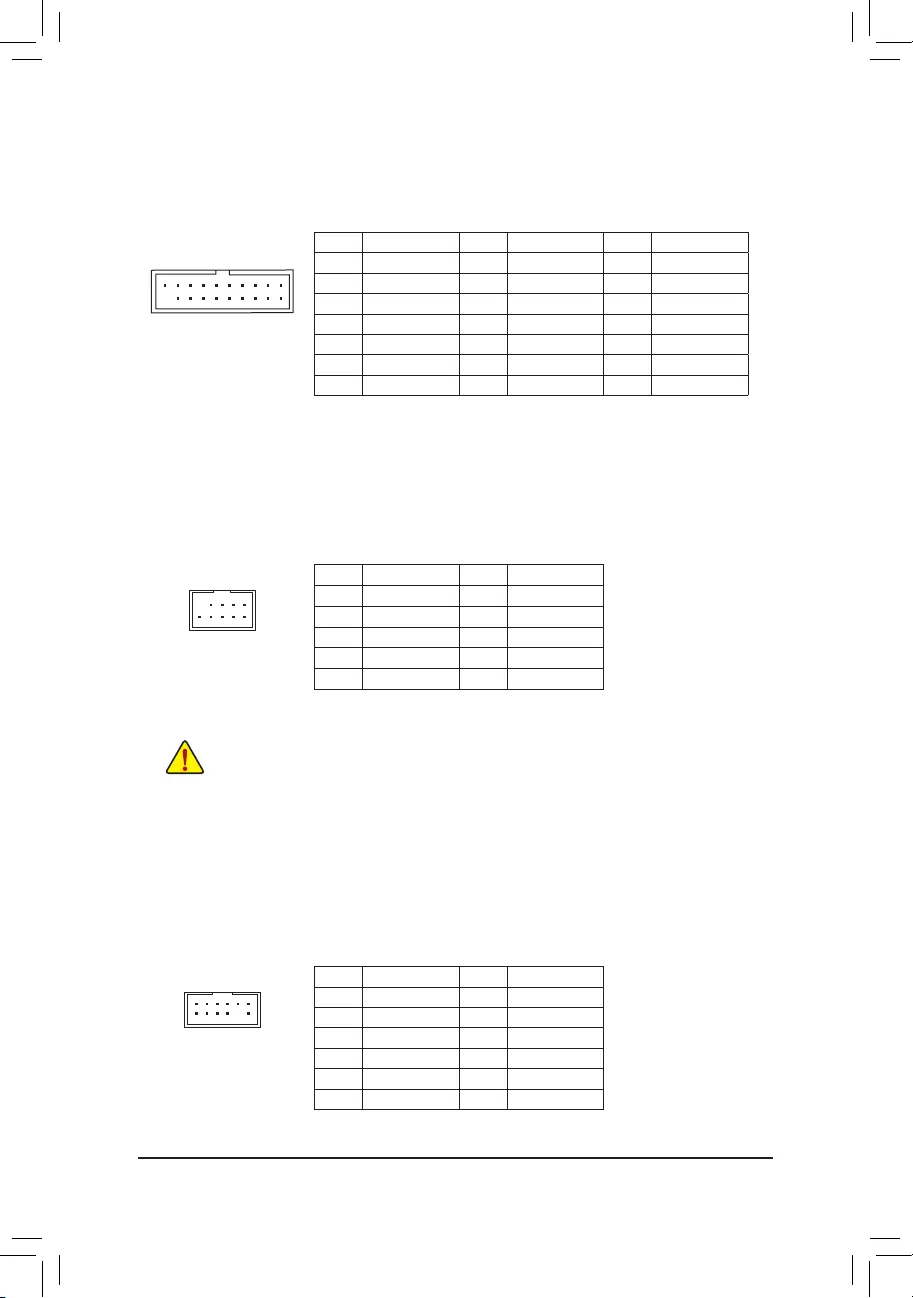
Pin No. Denition Pin No. Denition Pin No. Denition
1 VBUS 8 D1- 15 SSTX2-
2 SSRX1- 9 D1+ 16 GND
3 SSRX1+ 10 NC 17 SSRX2+
4 GND 11 D2+ 18 SSRX2-
5 SSTX1- 12 D2- 19 VBUS
6SSTX1+ 13 GND 20 No Pin
7 GND 14 SSTX2+
16) F_U32 (USB 3.2 Gen 1 Header)
The header conforms to USB 3.2 Gen 1 and USB 2.0 specication and can provide two USB ports. For
purchasing the optional 3.5″ front panel that provides two USB 3.2 Gen 1 ports, please contact the local
dealer.
F_USB30 F_U
B_
F_ F_
_
B
BS_
B
SB_
B
_S
S_
_
B
_U
_
B
S
123
123
123
123
1
1
1
1
BSS
S
_S
SSU
1 2 3 4 5
S3 BSSS
U
__ 3
F_USB3F
S _
S _
S _
SF
B_
B_
F
_0
S
S
_0F
_F
_
_
__B
U
S _S
_ SF_
B
USB0_B
B_
B_
F_USB3
F_USB303
_
_3U
S_
11
1 10
20
17) F_USB1/F_USB2 (USB 2.0/1.1 Headers)
The headers conform to USB 2.0/1.1 specication. Each USB header can provide two USB ports via an
optional USB bracket. For purchasing the optional USB bracket, please contact the local dealer.
Pin No. Denition Pin No. Denition
1 Power (5V) 6 USB DY+
2 Power (5V) 7 GND
3 USB DX- 8 GND
4 USB DY— 9 No Pin
5 USB DX+ 10 NC
•Do not plug the IEEE 1394 bracket (2×5-pin) cable into the USB 2.0/1.1 header.
•Prior to installing the USB bracket, be sure to turn off your computer and unplug the power cord
from the power outlet to prevent damage to the USB bracket.
10
9
2
1
18) TPM (Trusted Platform Module Header)
You may connect a TPM (Trusted Platform Module) to this header.
Pin No. Denition Pin No. Denition
1LAD0 7LAD3
2VCC3 8GND
3LAD1 9LFRAME
4No Pin 10 NC
5LAD2 11 SERIRQ
6LCLK 12 LRESET
F_USB30 F_U
B_
F_ F_
_
B
BS_
B
SB_
B
_S
S_
_
B
_U
_
B
S
123
123
123
123
1
1
1
1
BSS
S
_S
SSU
1 2 3 4 5
S3 BSSS
U
__ 3
F_USB3F
S _
S _
S _
SF
B_
B_
F
_0
S
S
_0F
_F
_
_
__B
U
S _S
_ SF_
B
USB0_B
B_
B_
F_USB3
F_USB303
_
_3U
S_
12
11
2
1
— 22 —
19) CLR_CMOS (Clear CMOS Jumper)
Use this jumper to clear the BIOS conguration and reset the CMOS values to factory defaults. To clear
the CMOS values, use a metal object like a screwdriver to touch the two pins for a few seconds.
•Always turn off your computer and unplug the power cord from the power outlet before clearing
the CMOS values.
•After system restart, go to BIOS Setup to load factory defaults (select Load Optimized Defaults) or
manually congure the BIOS settings (refer to Chapter 2, «BIOS Setup,» for BIOS congurations).
Open: Normal
Short: Clear CMOS Values
20) BAT (Battery)
The battery provides power to keep the values (such as BIOS congurations, date, and time information)
in the CMOS when the computer is turned off. Replace the battery when the battery voltage drops to a low
level, or the CMOS values may not be accurate or may be lost.
You may clear the CMOS values by removing the battery:
1. Turn off your computer and unplug the power cord.
2. Gently remove the battery from the battery holder and wait for one minute. (Or use a metal
object like a screwdriver to touch the positive and negative terminals of the battery holder,
making them short for 5 seconds.)
3. Replace the battery.
4. Plug in the power cord and restart your computer.
•Always turn off your computer and unplug the power cord before replacing the battery.
•Replace the battery with an equivalent one. Damage to your devices may occur if the battery is
replaced with an incorrect model.
•Contact the place of purchase or local dealer if you are not able to replace the battery by yourself
or uncertain about the battery model.
•When installing the battery, note the orientation of the positive side (+) and the negative side (-)
of the battery (the positive side should face up).
•Used batteries must be handled in accordance with local environmental regulations.
— 23 —
21) CPU/DRAM/VGA/BOOT (Status LEDs)
The status LEDs show whether the CPU, memory, graphics card, and operating system are working
properly after system power-on. If the CPU/DRAM/VGA LED is on, that means the corresponding device
is not working normally; if the BOOT LED is on, that means you haven’t entered the operating system yet.
CPU: CPU status LED
DRAM: Memory status LED
VGA: Graphics card status LED
BOOT: Operating system status LED
F_USB30 F_U
B_
F_ F_
_
B
BS_
B
SB_
B
_S
S_
_
B
_U
_
B
S
123
123
123
123
1
1
1
1
BSS
S
_S
SSU
1 2 3 4 5
S3 BSSS
U
__ 3
F_USB3F
S _
S _
S _
SF
B_
B_
F
_0
S
S
_0F
_F
_
_
__B
U
S _S
_ SF_
B
USB0_B
B_
B_
F_USB3
F_USB303
_
_3U
S_
CPU DRAM
VGA BOOT
BIOS (Basic Input and Output System) records hardware parameters of the system in the CMOS on the
motherboard. Its major functions include conducting the Power-On Self-Test (POST) during system startup,
saving system parameters and loading operating system, etc. BIOS includes a BIOS Setup program that allows
the user to modify basic system conguration settings or to activate certain system features.
When the power is turned off, the battery on the motherboard supplies the necessary power to the CMOS to
keep the conguration values in the CMOS.
To access the BIOS Setup program, press the <Delete> key during the POST when the power is turned on.
To upgrade the BIOS, use either the GIGABYTE Q-Flash or @BIOS utility.
•Q-Flash allows the user to quickly and easily upgrade or back up BIOS without entering the operating system.
•@BIOS is a Windows-based utility that searches and downloads the latest version of BIOS from the Internet
and updates the BIOS.
Chapter 2 BIOS Setup
•Because BIOS ashing is potentially risky, if you do not encounter problems using the current version of BIOS,
it is recommended that you not ash the BIOS. To ash the BIOS, do it with caution. Inadequate BIOS ashing
may result in system malfunction.
•It is recommended that you not alter the default settings (unless you need to) to prevent system instability or other
unexpected results. Inadequately altering the settings may result in system’s failure to boot. If this occurs, try to
clear the CMOS values and reset the board to default values. (Refer to the «Load Optimized Defaults» section in
this chapter or introductions of the battery/clear CMOS jumper in Chapter 1 for how to clear the CMOS values.)
2-1 Startup Screen
The following startup Logo screen will appear when the computer boots.
Function Keys
•When the system is not stable as usual, select the Load Optimized Defaults item to set your system to its defaults.
•The BIOS Setup menus described in this chapter are for reference only and may differ by BIOS version.
There are two different BIOS modes as follows and you can use the <F2> key to switch between the two modes.
Easy Mode allows users to quickly view their current system information or to make adjustments for optimum
performance. In Easy Mode, you can use your mouse to move through conguration items. The Advanced Mode
provides detailed BIOS settings. You can press the arrow keys on your keyboard to move among the items
and press <Enter> to accept or enter a sub-menu. Or you can use your mouse to select the item you want.
— 24 —
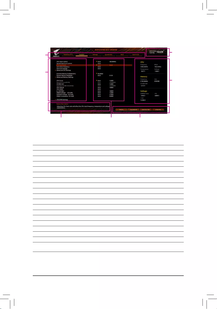
2-2 The Main Menu
Advanced Mode Function Keys
<f><g> Move the selection bar to select a setup menu
<h><i>Move the selection bar to select an conguration item on a menu
<Enter>/Double Click Execute command or enter a menu
<+>/<Page Up> Increase the numeric value or make changes
<—>/<Page Down> Decrease the numeric value or make changes
<F1> Show descriptions of the function keys
<F2> Switch to Easy Mode
<F3> Save the current BIOS settings to a prole
<F4> Load the BIOS settings from a prole created before
<F5> Restore the previous BIOS settings for the current submenus
<F6> Display the Smart Fan 5 screen
<F7> Load the Optimized BIOS default settings for the current submenus
<F8> Access the Q-Flash utility
<F10> Save all the changes and exit the BIOS Setup program
<F11> Switch to the Favorites submenu
<F12> Capture the current screen as an image and save it to your USB drive
<Insert> Add or remove a favorite option
<Ctrl>+<S> Display information on the installed memory
<Esc> Main Menu: Exit the BIOS Setup program
Submenus: Exit current submenu
Hardware
Information
Option Description Current Settings
Setup Menus
Conguration
Items
System
Time
Quick Access Bar allows you to quickly move to
the General Help, Easy Mode, Smart Fan 5, or
Q-Flash screen.
— 25 —
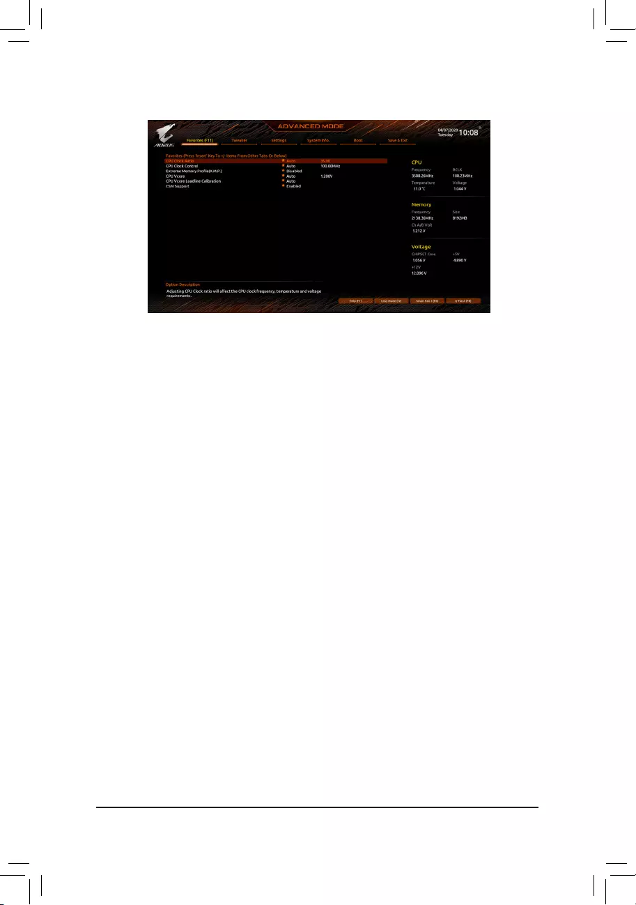
2-3 Favorites (F11)
Set your frequently used options as your favorites and use the <F11> key to quickly switch to the page where
all of your favorite options are located. To add or remove a favorite option, go to its original page and press
<Insert> on the option. The option is marked with a star sign if set as a «favorite.»
— 26 —
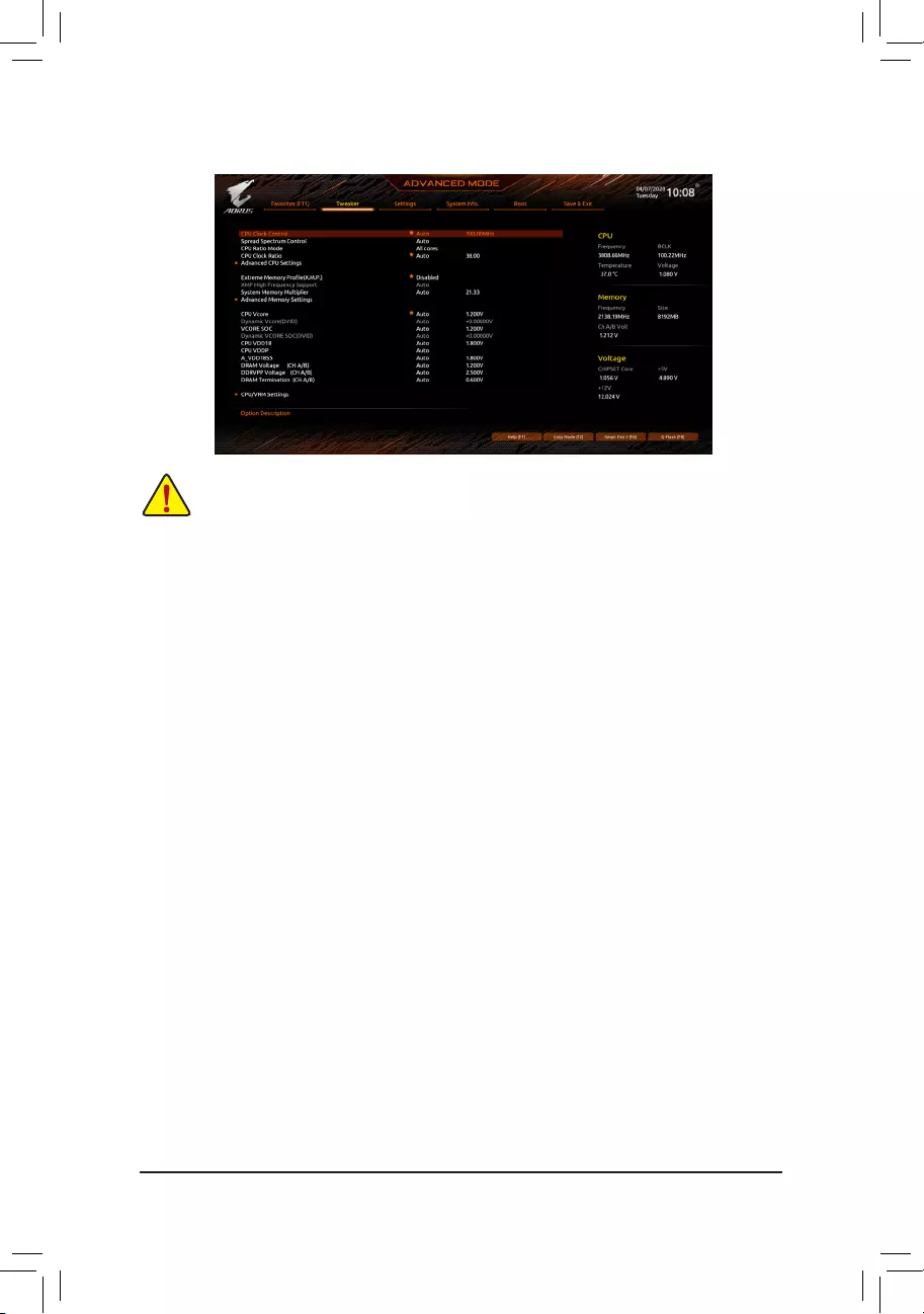
2-4 Tweaker
Whether the system will work stably with the overclock/overvoltage settings you made is dependent on your overall
system congurations. Incorrectly doing overclock/overvoltage may result in damage to CPU, chipset, or memory
and reduce the useful life of these components. This page is for advanced users only and we recommend you not to
alter the default settings to prevent system instability or other unexpected results. (Inadequately altering the settings
may result in system’s failure to boot. If this occurs, clear the CMOS values and reset the board to default values.)
&CPU Clock Control
Allows you to manually set the CPU base clock in 1 MHz increments. (Default: Auto)
Important: It is highly recommended that the CPU frequency be set in accordance with the CPU
specications.
&Spread Spectrum Control
Enables or disables CPU/PCIe Spread Spectrum. (Default: Auto)
&CPU Ratio Mode (Note)
Allows you to set the core ratio for all CPU cores or individual cores. (Default: All cores)
&CCD0 CCX0/1 Ratio (Note)
Allows you to manually set the core ratio for the CPU CCX0, 1 cores. This item is congurable only when
CPU Ratio Mode is set to Per CCX. (Default: Auto)
&CPU Clock Ratio
Allows you to alter the clock ratio for the installed CPU. The adjustable range is dependent on the CPU
being installed.
&GFX Clock Frequency (Note)
Allows you to alter the frequency for the GPU. After you alter the GFX Clock Frequency settings, make
sure to adjust the GFX Core Voltage settings. (Default: Auto)
NOTE: The adjustable range is dependent on the CPU being installed. Auto lets the BIOS automatically
congure this setting.
&GFX Core Voltage (Note)
Allows you to alter the voltage for the GPU. (Default: Auto)
NOTE: The adjustable range is dependent on the CPU being installed. Auto lets the BIOS automatically
congure this setting.
(Note) This item is present only when you install a CPU that supports this feature.
— 27 —

Advanced CPU Settings
&Core Performance Boost (Note 1)
Allows you to determine whether to enable the Core Performance Boost (CPB) technology, a CPU
performance-boost technology. (Default: Auto)
&SVM Mode
Virtualization enhanced by Virtualization Technology will allow a platform to run multiple operating systems
and applications in independent partitions. With virtualization, one computer system can function as multiple
virtual systems. (Default: Disabled)
&AMD Cool&Quiet function
Enabled Lets the AMD Cool’n’Quiet driver dynamically adjust the CPU clock and VID to
reduce heat output from your computer and its power consumption. (Default)
Disabled Disables this function.
&PPC Adjustment (Note 1)
Allows you to x the PState of the CPU. (Default: PState 0)
&Global C-state Control (Note 1)
Allows you to determine whether to let the CPU enter C states. When enabled, the CPU core frequency
will be reduced during system halt state to decrease power consumption. (Default: Auto)
&Power Supply Idle Control (Note 1)
Enables or disables Package C6 State.
Typical Current Idle Disables this function.
Low Current Idle Enables this function.
Auto Lets the BIOS automatically congure this setting. (Default)
&CCD Control (Note 1)
Sets the number of CCDs to be used. (Default: Auto)
&Downcore Control
Allows you to select the number of CPU cores to enable (the number of CPU cores may vary by CPU).
(Default: Auto)
&SMT Mode
Allows you to enable or disable the CPU Simultaneous Multi-Threading technology. (Default: Auto)
&CPPC (Note 1)
Enables or disables the CPPC feature. (Default: Auto)
&CPPC Preferred Cores (Note 1)
Enables or disables the CPPC Preferred Cores feature. (Default: Auto)
&Extreme Memory Prole (X.M.P.) (Note 2)
Allows the BIOS to read the SPD data on XMP memory module(s) to enhance memory performance when
enabled.
Disabled Disables this function. (Default)
Prole1 Uses Prole 1 settings.
Prole2 (Note 2) Uses Prole 2 settings.
&XMP High Frequency Support (Note 2)
Allows you to select the compatibility level for high-frequency memory. This item is congurable only when
Extreme Memory Prole (X.M.P.) is set to Prole1 or Prole2. (Default: Auto)
&System Memory Multiplier
Allows you to set the system memory multiplier. Auto sets memory multiplier according to memory SPD
data. (Default: Auto)
(Note 1) This item is present only when you install a CPU that supports this feature.
(Note 2) This item is present only when you install a CPU and a memory module that support this feature.
— 28 —

Advanced Memory Settings
Memory Subtimings
d Standard Timing Control, Advanced Timing Control, CAD Bus Setup Timing, CAD Bus
Drive Strength, Data Bus Conguration
These sections provide memory timing settings. Note: Your system may become unstable or fail to boot
after you make changes on the memory timings. If this occurs, please reset the board to default values by
loading optimized defaults or clearing the CMOS values.
SPD Info
Displays information on the installed memory.
& CPU Vcore/Dynamic Vcore(DVID)/VCORE SOC/Dynamic VCORE SOC(DVID)/CPU VDD18/
CPU VDDP/A_VDD18S5/DRAM Voltage (CH A/B)/DDRVPP Voltage (CH A/B)/DRAM
Termination (CH A/B)
These items allow you to adjust the CPU Vcore and memory voltages.
CPU/VRM Settings
This submenu allows you to congure Load-Line Calibration level, over-voltage protection level, over-current
protection level, and PWM phases.
— 29 —
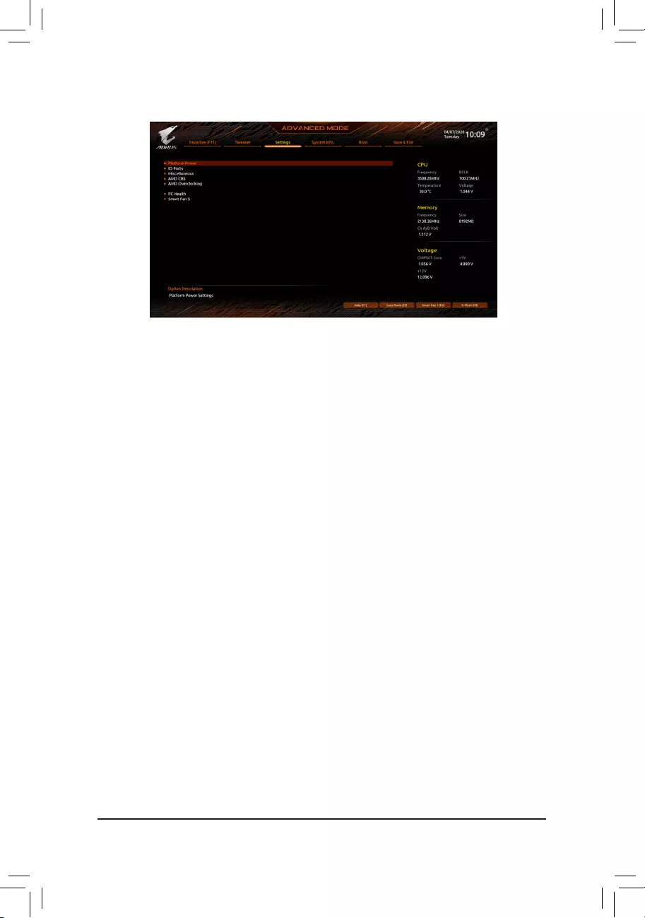
2-5 Settings
Platform Power
&AC BACK
Determines the state of the system after the return of power from an AC power loss.
Memory The system returns to its last known awake state upon the return of the AC power.
Always On The system is turned on upon the return of the AC power.
Always Off The system stays off upon the return of the AC power. (Default)
&ErP
Determines whether to let the system consume least power in S5 (shutdown) state. (Default: Disabled)
Note: When this item is set to Enabled, the Resume by Alarm function becomes unavailable.
&Soft-Off by PWR-BTTN
Congures the way to turn off the computer in MS-DOS mode using the power button.
Instant-Off Press the power button and then the system will be turned off instantly. (Default)
Delay 4 Sec. Press and hold the power button for 4 seconds to turn off the system. If the power
button is pressed for less than 4 seconds, the system will enter suspend mode.
&Power Loading
Enables or disables dummy load. When the power supply is at low load, a self-protection will activate causing
it to shutdown or fail. If this occurs, please set to Enabled. Auto lets the BIOS automatically congure this
setting. (Default: Auto)
&Resume by Alarm
Determines whether to power on the system at a desired time. (Default: Disabled)
If enabled, set the date and time as following:
Wake up day: Turn on the system at a specic time on each day or on a specic day in a month.
Wake up hour/minute/second: Set the time at which the system will be powered on automatically.
Note: When using this function, avoid inadequate shutdown from the operating system or removal of the
AC power, or the settings may not be effective.
&Wake on LAN
Enables or disables the wake on LAN function. (Default: Enabled)
&High Precision Event Timer
Enables or disables High Precision Event Timer (HPET) in the operating system. (Default: Enabled)
&CEC 2019 Ready
Allows you to select whether to allow the system to adjust power consumption when it is in shutdown, idle,
or standby state in order to comply with the CEC (California Energy Commission) 2019 Standards. (Default:
Disabled)
— 30 —

IO Ports
&Initial Display Output
Species the rst initiation of the monitor display from the installed PCI Express graphics card or the onboard
graphics.
IGD Video (Note) Sets the onboard graphics as the rst display.
PCIe 1 Slot Sets the graphics card on the PCIEX16 slot as the rst display. (Default)
PCIe 2 Slot Sets the graphics card on the PCIEX4_1 slot as the rst display.
PCIe 3 Slot Sets the graphics card on the PCIEX4_2 slot as the rst display.
&Integrated Graphics (Note)
Enables or disables the onboard graphics function.
Auto The BIOS will automatically enable or disable the onboard graphics depending
on the graphics card being installed. (Default)
Forces Enables the onboard graphics.
Disabled Disables the onboard graphics.
&UMA Mode (Note)
Specify the UMA mode.
Auto Lets the BIOS automatically congure this setting. (Default)
UMA Specied Sets the UMA Frame Buffer Size.
UMA Auto Sets the display resolution.
UMA Game Optimized Adjusts the frame buffer size based on the total system memory size.
This item is congurable only when Integrated Graphics is set to Forces.
&UMA Frame Buffer Size (Note)
Frame buffer size is the total amount of system memory allocated solely for the onboard graphics controller.
MS-DOS, for example, will use only this memory for display. Options are: Auto (default), 64M~2G.
This item is congurable only when UMA Mode is set to UMA Specied.
&Display Resolution (Note)
Allows you to set the display resolution. Options are: Auto (default), 1920×1080 and below, 2560×1600,
3840×2160.
This item is congurable only when UMA Mode is set to UMA Auto.
&HD Audio Controller
Enables or disables the onboard audio function. (Default: Enabled)
If you wish to install a 3rd party add-in audio card instead of using the onboard audio, set this item to
Disabled.
&PCIEX16 Bifurcation
Allows you to determine how the bandwidth of the PCIEX16 slot is divided. Options: Auto, PCIE 2×8,
PCIE 1×8/2×4, PCIE 2×4/1×8, PCIE 4×4. (Default: Auto)
&Above 4G Decoding
Enables or disables 64-bit capable devices to be decoded in above 4 GB address space (only if your system
supports 64-bit PCI decoding). Set to Enabled if more than one advanced graphics card are installed and
their drivers are not able to be launched when entering the operating system (because of the limited 4 GB
memory address space). (Default: Disabled)
&Onboard LAN Controller
Enables or disables the onboard LAN function. (Default: Enabled)
If you wish to install a 3rd party add-in network card instead of using the onboard LAN, set this item to
Disabled.
(Note) This item is present only when you install a CPU that supports this feature.
— 31 —

USB Conguration
&Legacy USB Support
Allows USB keyboard/mouse to be used in MS-DOS. (Default: Enabled)
&XHCI Hand-off
Determines whether to enable XHCI Hand-off feature for an operating system without XHCI Hand-off
support. (Default: Enabled)
&USB Mass Storage Driver Support
Enables or disables support for USB storage devices. (Default: Enabled)
&Port 60/64 Emulation
Enables or disables emulation of I/O ports 64h and 60h. This should be enabled for full legacy support
for USB keyboards/mice in MS-DOS or in operating system that does not natively support USB devices.
(Default: Disabled)
&Mass Storage Devices
Displays a list of connected USB mass storage devices. This item appears only when a USB storage device
is installed.
NVMe Conguration
Displays information on your M.2 NVME PCIe SSD if installed.
SATA Conguration
&SATA Mode
Enables or disables RAID for the SATA controllers integrated in the Chipset or congures the SATA controllers
to AHCI mode.
RAID Enables RAID for the SATA controller.
AHCI Congures the SATA controllers to AHCI mode. Advanced Host Controller Interface
(AHCI) is an interface specication that allows the storage driver to enable advanced
Serial ATA features such as Native Command Queuing and hot plug. (Default)
&NVMe RAID mode
Allows you to determine whether to use your M.2 NVMe PCIe SSDs to congure RAID. (Default: Disabled)
&Chipset SATA Port Enable
Enables or disables the integrated SATA controllers. (Default: Enabled)
&Chipset SATA Port 0/1/2/3/4/5
Displays the information of the connected SATA device(s).
Network Stack Conguration
&Network Stack
Disables or enables booting from the network to install a GPT format OS, such as installing the OS from
the Windows Deployment Services server. (Default: Disabled)
&IPv4 PXE Support
Enables or disables IPv4 PXE Support. This item is congurable only when Network Stack is enabled.
&IPv4 HTTP Support
Enables or disables HTTP boot support for IPv4. This item is congurable only when Network Stack is
enabled.
&IPv6 PXE Support
Enables or disables IPv6 PXE Support. This item is congurable only when Network Stack is enabled.
&IPv6 HTTP Support
Enables or disables HTTP boot support for IPv6. This item is congurable only when Network Stack is
enabled.
— 32 —

&PXE boot wait time
Allows you to congure how long to wait before you can press <Esc> to abort the PXE boot. This item is
congurable only when Network Stack is enabled. (Default: 0)
&Media detect count
Allows you to set the number of times to check the presence of media. This item is congurable only when
Network Stack is enabled. (Default: 1)
Realtek PCIe 2.5GBE Family Controller
This sub-menu provides information on LAN conguration and related conguration options.
Miscellaneous
&LEDs in System Power On State
Allows you to enable or disable motherboard LED lighting when the system is on.
Off Disables the selected lighting mode when the system is on.
On Enables the selected lighting mode when the system is on. (Default)
&LEDs in Sleep, Hibernation, and Soft Off States
Allows you to set the lighting mode of the motherboard LEDs in system S3/S4/S5 state.
This item is congurable when LEDs in System Power On State is set to On.
Off Disables the selected lighting mode when the system enters S3/S4/S5 state. (Default)
On Enables the selected lighting mode when the system enters S3/S4/S5 state.
&PCIe Slot Conguration
Allows you to set the operation mode of the PCI Express slots to Gen 1, Gen 2, Gen 3, or Gen 4 (Note). Actual
operation mode is subject to the hardware specication of each slot. Auto lets the BIOS automatically
congure this setting. (Default: Auto)
&3DMark01 Enhancement
Allows you to determine whether to enhance some legacy benchmark performance. (Default: Disabled)
&IOMMU
Enables or disables AMD IOMMU support. (Default: Auto)
&AMD CPU fTPM
Enables or disables the TPM 2.0 function integrated in the AMD CPU. (Default: Disabled)
Trusted Computing
Enables or disables Trusted Platform Module (TPM).
AMD CBS
This sub-menu provides AMD CBS-related conguration options.
PC Health
&Reset Case Open Status
Disabled Keeps or clears the record of previous chassis intrusion status. (Default)
Enabled Clears the record of previous chassis intrusion status and the Case Open eld will
show «No» at next boot.
&Case Open
Displays the detection status of the chassis intrusion detection device attached to the motherboard CI
header. If the system chassis cover is removed, this eld will show «Yes», otherwise it will show «No». To
clear the chassis intrusion status record, set Reset Case Open Status to Enabled, save the settings to
the CMOS, and then restart your system.
(Note) This item is present only when you install a CPU that supports this feature.
— 33 —

& CPU Vcore/CPU VDDP/CPU VDD18/DDRVtt A/B/DRAM Channel A/B Voltage/PM_CLDO12/
+3.3V/+5V/CHIPSET Core/+12V/VCORE SOC
Displays the current system voltages.
Smart Fan 5
&Monitor
Allows you to select a target to monitor and to make further adjustment. (Default: CPU FAN)
&Fan Speed Control
Allows you to determine whether to enable the fan speed control function and adjust the fan speed.
Normal Allows the fan to run at different speeds according to the temperature. You can adjust
the fan speed with System Information Viewer based on your system requirements.
(Default)
Silent Allows the fan to run at slow speeds.
Manual Allows you to control the fan speed in the curve graph.
Full Speed Allows the fan to run at full speeds.
&Fan Control Use Temperature Input
Allows you to select the reference temperature for fan speed control.
&Temperature Interval
Allows you to select the temperature interval for fan speed change.
&Fan/Pump Control mode
Auto Lets the BIOS automatically detect the type of fan/pump installed and sets the optimal
control mode. (Default)
Voltage Voltage mode is recommended for a 3-pin fan/pump.
PWM PWM mode is recommended for a 4-pin fan/pump.
&Fan/Pump Stop
Enables or disables the fan/pump stop function. You can set the temperature limit using the temperature
curve. The fan or pump stops operation when the temperature is lower than the limit. (Default: Disabled)
&Temperature
Displays the current temperature of the selected target area.
&Fan Speed
Displays current fan/pump speeds.
&Flow Rate
Displays the ow rate of your water cooling system.
&Temperature Warning Control
Sets the warning threshold for temperature. When temperature exceeds the threshold, BIOS will emit
warning sound. Options are: Disabled (default), 60oC/140oF, 70oC/158oF, 80oC/176oF, 90oC/194oF.
&Fan/Pump Fail Warning
Allows the system to emit warning sound if the fan/pump is not connected or fails. Check the fan/pump
condition or fan/pump connection when this occurs. (Default: Disabled)
— 34 —
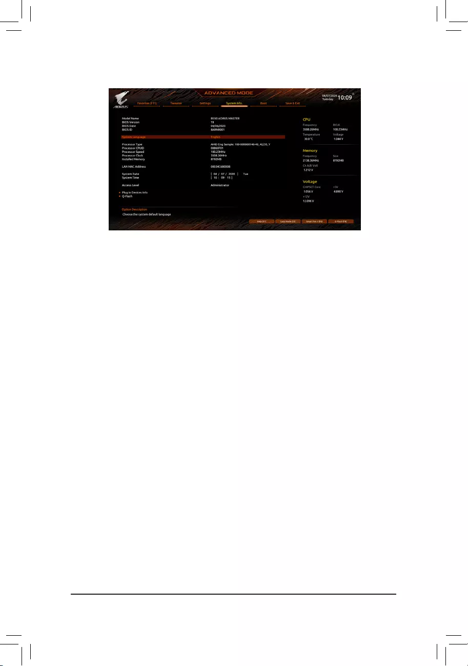
2-6 System Info.
This section provides information on your motherboard model and BIOS version. You can also select the default
language used by the BIOS and manually set the system time.
&System Language
Selects the default language used by the BIOS.
&System Date
Sets the system date. The date format is week (read-only), month, date, and year. Use <Enter> to switch
between the Month, Date, and Year elds and use the <Page Up> or <Page Down> key to set the desired
value.
&System Time
Sets the system time. The time format is hour, minute, and second. For example, 1 p.m. is 13:00:00. Use
<Enter> to switch between the Hour, Minute, and Second elds and use the <Page Up> or <Page Down>
key to set the desired value.
&Access Level
Displays the current access level depending on the type of password protection used. (If no password is
set, the default will display as Administrator.) The Administrator level allows you to make changes to all
BIOS settings; the User level only allows you to make changes to certain BIOS settings but not all.
Plug in Devices Info
Displays information on your SATA, PCI Express, and M.2 devices if installed.
Q-Flash
Allows you to access the Q-Flash utility to update the BIOS or back up the current BIOS conguration.
— 35 —
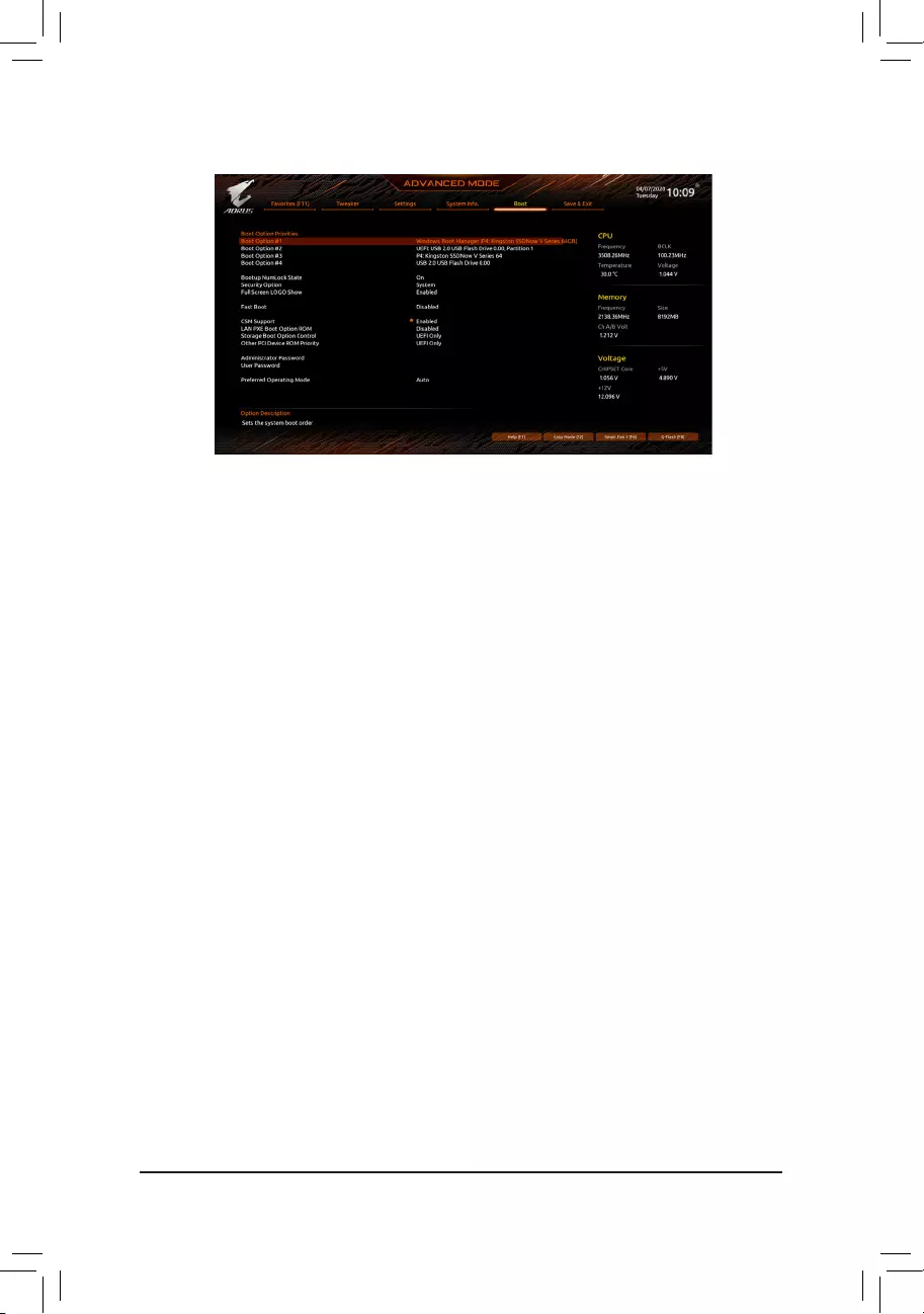
2-7 Boot
&Boot Option Priorities
Species the overall boot order from the available devices. Removable storage devices that support GPT
format will be prexed with «UEFI:» string on the boot device list. To boot from an operating system that
supports GPT partitioning, select the device prexed with «UEFI:» string.
Or if you want to install an operating system that supports GPT partitioning such as Windows 10 64-bit,
select the optical drive that contains the Windows 10 64-bit installation disc and is prexed with «UEFI:»
string.
&Bootup NumLock State
Enables or disables Numlock feature on the numeric keypad of the keyboard after the POST. (Default: On)
&Security Option
Species whether a password is required every time the system boots, or only when you enter BIOS Setup.
After conguring this item, set the password(s) under the Administrator Password/User Password item.
Setup A password is only required for entering the BIOS Setup program.
System A password is required for booting the system and for entering the BIOS Setup program.
(Default)
&Full Screen LOGO Show
Allows you to determine whether to display the GIGABYTE Logo at system startup. Disabled skips the
GIGABYTE Logo when the system starts up. (Default: Enabled)
&Fast Boot
Enables or disables Fast Boot to shorten the OS boot process. Ultra Fast provides the fastest bootup
speed. (Default: Disabled)
&SATA Support
Last Boot SATA Devices Only Except for the previous boot drive, all SATA devices are disabled
before the OS boot process completes. (Default)
All SATA Devices All SATA devices are functional in the operating system and during the POST.
This item is congurable only when Fast Boot is set to Enabled or Ultra Fast.
&NVMe Support
Allows you to enable or disable NVMe device(s). (Default: Enabled)
This item is congurable only when Fast Boot is set to Enabled or Ultra Fast.
— 36 —

&VGA Support
Allows you to select which type of operating system to boot.
Auto Enables legacy option ROM only.
EFI Driver Enables EFI option ROM. (Default)
This item is congurable only when Fast Boot is set to Enabled or Ultra Fast.
&USB Support
Disabled All USB devices are disabled before the OS boot process completes.
Full Initial All USB devices are functional in the operating system and during the POST.
(Default)
Partial Initial Part of the USB devices are disabled before the OS boot process completes.
This item is congurable only when Fast Boot is set to Enabled. This function is disabled when Fast Boot
is set to Ultra Fast.
&NetWork Stack Driver Support
Disabled Disables booting from the network. (Default)
Enabled Enables booting from the network.
This item is congurable only when Fast Boot is set to Enabled or Ultra Fast.
&CSM Support
Enables or disables UEFI CSM (Compatibility Support Module) to support a legacy PC boot process.
Disabled Disables UEFI CSM and supports UEFI BIOS boot process only.
Enabled Enables UEFI CSM. (Default)
&LAN PXE Boot Option ROM
Allows you to select whether to enable the legacy option ROM for the LAN controller. (Default: Disabled)
This item is congurable only when CSM Support is set to Enabled.
&Storage Boot Option Control
Allows you to select whether to enable the UEFI or legacy option ROM for the storage device controller.
Disabled Disables option ROM.
UEFI Only Enables UEFI option ROM only. (Default)
Legacy Only Enables legacy option ROM only.
This item is congurable only when CSM Support is set to Enabled.
&Other PCI Device ROM Priority
Allows you to select whether to enable the UEFI or Legacy option ROM for the PCI device controller other
than the LAN, storage device, and graphics controllers.
Disabled Disables option ROM.
UEFI Only Enables UEFI option ROM only. (Default)
Legacy Only Enables legacy option ROM only.
This item is congurable only when CSM Support is set to Enabled.
&Administrator Password
Allows you to congure an administrator password. Press <Enter> on this item, type the password, and
then press <Enter>. You will be requested to conrm the password. Type the password again and press
<Enter>. You must enter the administrator password (or user password) at system startup and when entering
BIOS Setup. Differing from the user password, the administrator password allows you to make changes to
all BIOS settings.
— 37 —

&User Password
Allows you to congure a user password. Press <Enter> on this item, type the password, and then press
<Enter>. You will be requested to conrm the password. Type the password again and press <Enter>.
You must enter the administrator password (or user password) at system startup and when entering BIOS
Setup. However, the user password only allows you to make changes to certain BIOS settings but not all.
To cancel the password, press <Enter> on the password item and when requested for the password, enter
the correct one rst. When prompted for a new password, press <Enter> without entering any password.
Press <Enter> again when prompted to conrm.
NOTE: Before setting the User Password, be sure to set the Administrator Password rst.
Secure Boot
Allows you to enable or disable Secure Boot and congure related settings. This item is congurable only
when CSM Support is set to Disabled.
&Preferred Operating Mode
Allows you to select whether to enter Easy mode or Advanced mode after entering BIOS Setup. Auto
enters the BIOS mode where it was last time. (Default: Auto)
— 38 —
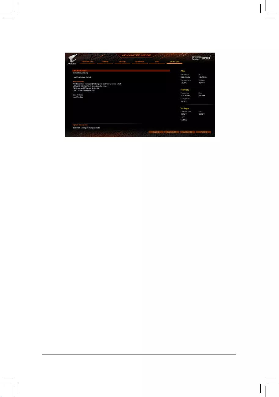
2-8 Save & Exit
&Save & Exit Setup
Press <Enter> on this item and select Yes. This saves the changes to the CMOS and exits the BIOS Setup
program. Select No or press <Esc> to return to the BIOS Setup Main Menu.
&Exit Without Saving
Press <Enter> on this item and select Yes. This exits the BIOS Setup without saving the changes made
in BIOS Setup to the CMOS. Select No or press <Esc> to return to the BIOS Setup Main Menu.
&Load Optimized Defaults
Press <Enter> on this item and select Yes to load the optimal BIOS default settings. The BIOS defaults
settings help the system to operate in optimum state. Always load the Optimized defaults after updating
the BIOS or after clearing the CMOS values.
&Boot Override
Allows you to select a device to boot immediately. Press <Enter> on the device you select and select Yes
to conrm. Your system will restart automatically and boot from that device.
&Save Proles
This function allows you to save the current BIOS settings to a prole. You can create up to 8 proles and
save as Setup Prole 1~ Setup Prole 8. Press <Enter> to complete. Or you can select Select File in
HDD/FDD/USB to save the prole to your storage device.
&Load Proles
If your system becomes unstable and you have loaded the BIOS default settings, you can use this function
to load the BIOS settings from a prole created before, without the hassles of reconguring the BIOS
settings. First select the prole you wish to load and then press <Enter> to complete. You can select Select
File in HDD/FDD/USB to input the prole previously created from your storage device or load the prole
automatically created by the BIOS, such as reverting the BIOS settings to the last settings that worked
properly (last known good record).
— 39 —
Chapter 3 Appendix
3-1 Conguring a RAID Set
(Note) An M.2 PCIe SSD cannot be used to set up a RAID set either with an M.2 SATA SSD or a SATA hard drive.
C. UEFI RAID Conguration
Steps:
1. In BIOS Setup, go to Boot and set CSM Support to Disabled. Save the changes and exit BIOS Setup.
2. After the system reboot, enter BIOS Setup again. Then enter the SettingsIO PortsRAIDXpert2
Conguration Utility sub-menu.
3. On the RAIDXpert2 Conguration Utility screen, press <Enter> on Array Management to enter the Create
Array screen. Then, select a RAID level. RAID levels supported include RAID 0, RAID 1, and RAID 10 (the
selections available depend on the number of the hard drives being installed). Next, press <Enter> on Select
Physical Disks to enter the Select Physical Disks screen.
4. On the Select Physical Disks screen, select the hard drives to be included in the RAID array and set them
to Enabled. Next, use the down arrow key to move to Apply Changes and press <Enter>. Then return
to the previous screen and set the Select CacheTagSize, Read Cache Policy and Write Cache Policy.
5. Move to Create Array and press <Enter> to begin.
6. After completing, you’ll be brought back to the Array Management screen. Under Manage Array Properties
you can see the new RAID volume and information on RAID level, array name, array capacity, etc.
Before you begin, please prepare the following items:
•At least two SATA hard drives or SSDs. (Note) (To ensure optimal performance, it is recommended that you use
two hard drives with identical model and capacity).
•Windows setup disc.
•Motherboard driver disc.
•A USB thumb drive.
Conguring the Onboard SATA Controller
A. Installing SATA hard drive(s) in your computer
Install the hard drives/SSDs in the SATA/M.2 connectors on the motherboard. Then connect the power connectors
from your power supply to the hard drives.
B. Conguring SATA controller mode in BIOS Setup
Make sure to congure the SATA controller mode correctly in system BIOS Setup.
Steps:
Turn on your computer and press <Delete> to enter BIOS Setup during the POST (Power-On Self-Test). Under
SettingsIO Ports, set SATA CongurationSATA Mode to RAID. Then save the settings and restart your
computer. (If you want to use NVMe PCIe SSDs to congure RAID, make sure to set NVMe RAID mode to
Enabled.)
RAID Levels
RAID 0 RAID 1 RAID 10
Minimum Number of
Hard Drives ≥2 2 4
Array Capacity Number of hard drives *
Size of the smallest drive
Size of the smallest drive (Number of hard drives/2) *
Size of the smallest drive
Fault Tolerance No Yes Yes
The BIOS Setup menus described in this section may differ from the exact settings for your
motherboard. The actual BIOS Setup menu options you will see shall depend on the motherboard
you have and the BIOS version.
— 40 —
Please visit GIGABYTE’s website for details on conguring a RAID array.
Install the RAID driver and operating system
With the correct BIOS settings, you are ready to install the operating system.
Installing the Operating System
As some operating systems already include RAID driver, you do not need to install separate RAID driver during
the Windows installation process. After the operating system is installed, we recommend that you install all
required drivers from the motherboard driver disc using «Xpress Install» to ensure system performance and
compatibility. If the operating system to be installed requires that you provide additional RAID driver during the
OS installation process, please refer to the steps below:
1. Copy the Hw10 folder under the BootDrv folder in the driver disc to your USB thumb drive.
2. Boot from the Windows setup disc and perform standard OS installation steps. When the screen requesting
you to load the driver appears, select Browse.
3. Insert the USB thumb drive and then browse to the location of the driver. The location of the drivers is as
follows:
Hw10RAIDx64
4. Select AMD-RAID Bottom Device rst and click Next to load the driver. Then select AMD-RAID Controller
and click Next to load the driver. Finally, continue the OS installation.
— 41 —
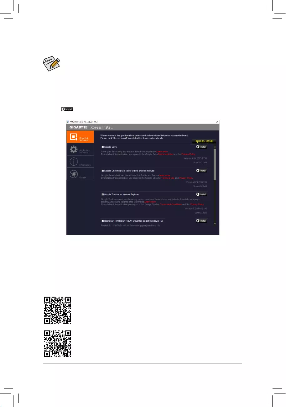
•Before installing the drivers, rst install the operating system.
•After installing the operating system, insert the motherboard driver disc into your optical drive. Click
on the message «Tap to choose what happens with this disc» on the top-right corner of the screen
and select «Run Run.exe.» (Or go to My Computer, double-click the optical drive and execute the
Run.exe program.)
«Xpress Install» will automatically scan your system and then list all of the drivers that are recommended to
install. You can click the Xpress Install button and «Xpress Install» will install all of the selected drivers. Or click
the arrow icon to individually install the drivers you need.
Please visit GIGABYTE’s website for more software information.
3-2 Drivers Installation
Please visit GIGABYTE’s website for more troubleshooting information.
— 42 —

3-3 Debug LED Codes
Code Description
10 PEI Core is started.
11 Pre-memory CPU initialization is started.
12~14 Reserved.
15 Pre-memory North-Bridge initialization is started.
16~18 Reserved.
19 Pre-memory South-Bridge initialization is started.
1A~2A Reserved.
2B~2F Memory initialization.
31 Memory installed.
32~36 CPU PEI initialization.
37~3A IOH PEI initialization.
3B~3E PCH PEI initialization.
3F~4F Reserved.
60 DXE Core is started.
61 NVRAM initialization.
62 Installation of the PCH runtime services.
63~67 CPU DXE initialization is started.
68 PCI host bridge initialization is started.
69 IOH DXE initialization.
6A IOH SMM initialization.
6B~6F Reserved.
70 PCH DXE initialization.
71 PCH SMM initialization.
72 PCH devices initialization.
73~77 PCH DXE initialization (PCH module specic).
78 ACPI Core initialization.
79 CSM initialization is started.
7A~7F Reserved for AMI use.
80~8F Reserved for OEM use (OEM DXE initialization codes).
90 Phase transfer to BDS (Boot Device Selection) from DXE.
91 Issue event to connect drivers.
Regular Boot
— 43 —
Code Description
92 PCI Bus initialization is started.
93 PCI Bus hot plug initialization.
94 PCI Bus enumeration for detecting how many resources are requested.
95 Check PCI device requested resources.
96 Assign PCI device resources.
97 Console Output devices connect (ex. Monitor is lighted).
98 Console input devices connect (ex. PS2/USB keyboard/mouse are activated).
99 Super IO initialization.
9A USB initialization is started.
9B Issue reset during USB initialization process.
9C Detect and install all currently connected USB devices.
9D Activated all currently connected USB devices.
9E~9F Reserved.
A0 IDE initialization is started.
A1 Issue reset during IDE initialization process.
A2 Detect and install all currently connected IDE devices.
A3 Activated all currently connected IDE devices.
A4 SCSI initialization is started.
A5 Issue reset during SCSI initialization process.
A6 Detect and install all currently connected SCSI devices.
A7 Activated all currently connected SCSI devices.
A8 Verify password if needed.
A9 BIOS Setup is started.
AA Reserved.
AB Wait user command in BIOS Setup.
AC Reserved.
AD Issue Ready To Boot event for OS Boot.
AE Boot to Legacy OS.
AF Exit Boot Services.
B0 Runtime AP installation begins.
B1 Runtime AP installation ends.
B2 Legacy Option ROM initialization.
B3 System reset if needed.
— 44 —
Code Description
B4 USB device hot plug-in.
B5 PCI device hot plug.
B6 Clean-up of NVRAM.
B7 Recongure NVRAM settings.
B8~BF Reserved.
C0~CF Reserved.
Code Description
E0 S3 Resume is stared (called from DXE IPL).
E1 Fill boot script data for S3 resume.
E2 Initializes VGA for S3 resume.
E3 OS S3 wake vector call.
S3 Resume
Code Description
F0 Recovery mode will be triggered due to invalid rmware volume detection.
F1 Recovery mode will be triggered by user decision.
F2 Recovery is started.
F3 Recovery rmware image is found.
F4 Recovery rmware image is loaded.
F5~F7 Reserved for future AMI progress codes.
Recovery
Code Description
50~55 Memory initialization error occurs.
56 Invalid CPU type or speed.
57 CPU mismatch.
58 CPU self test failed or possible CPU cache error.
59 CPU micro-code is not found or micro-code update is failed.
5A Internal CPU error.
5B Reset PPI is failed.
5C~5F Reserved.
D0 CPU initialization error.
D1 IOH initialization error.
Error
— 45 —
Code Description
D2 PCH initialization error.
D3 Some of the Architectural Protocols are not available.
D4 PCI resource allocation error. Out of Resources.
D5 No Space for Legacy Option ROM initialization.
D6 No Console Output Devices are found.
D7 No Console Input Devices are found.
D8 It is an invalid password.
D9~DA Can’t load Boot Option.
DB Flash update is failed.
DC Reset protocol is failed.
DE~DF Reserved.
E8 S3 resume is failed.
E9 S3 Resume PPI is not found.
EA S3 Resume Boot Script is invalid.
EB S3 OS Wake call is failed.
EC~EF Reserved.
F8 Recovery PPI is invalid.
<F9> Recovery capsule is not found.
FA Invalid recovery capsule.
FB~FF Reserved.
— 46 —

Regulatory Notices
CAUTION:
The manufacturer is not responsible for any interference caused by unauthorized modications and/or use of unauthorized antennas. Such
changes and/or modications not expressly approved by the party responsible for compliance of this device could void the user’s authority to
operate the equipment.
RF exposure statement / Antenna Use
Further RF exposure reduction can be achieved if the product can be kept as far as possible from the user body or set the device to lower output
power if such function is available.
•Do not touch or move antenna while the unit is transmitting or receiving.
•Do not hold any component containing the radio such that the antenna is very close or touching any exposed parts of the body, especially the
face or eyes, while transmitting.
•Do not operate the radio or attempt to transmit data unless the antenna is connected; this behavior may cause damage to the radio.
United States of America, Federal Communications Commission Statement
Supplier’s Declaration of Conformity
47 CFR § 2.1077 Compliance Information
Product Name: Motherboard
Trade Name: GIGABYTE
Model Number: B550 AORUS MASTER
Responsible Party – U.S. Contact Information: G.B.T. Inc.
Address: 17358 Railroad street, City Of Industry, CA91748
Tel.: 1-626-854-9338
Internet contact information: https://www.gigabyte.com
FCC Compliance Statement:
This device complies with Part 15 of the FCC Rules, Subpart B, Unintentional Radiators.
Operation is subject to the following two conditions: (1) This device may not cause harmful interference, and (2) this
device must accept any interference received, including interference that may cause undesired operation.
This equipment has been tested and found to comply with the limits for
a Class B digital device, pursuant to Part 15 of the FCC Rules. These
limits are designed to provide reasonable protection against harmful
interference in a residential installation. This equipment generates,
uses and can radiate radio frequency energy and, if not installed
and used in accordance with manufacturer’s instructions, may cause
harmful interference to radio communications. However, there is no
guarantee that interference will not occur in a particular installation. If
this equipment does cause harmful interference to radio or television
reception, which can be determined by turning the equipment off and
on, the user is encouraged to try to correct the interference by one or
more of the following measures:
•Reorient or relocate the receiving antenna.
•Increase the separation between the equipment and receiver.
•Connect the equipment to an outlet on a circuit different from that to
which the receiver is connected.
•Consult the dealer or an experienced radio/TV technician for help.
Notice for 5GHz
Operations in the 5.15-5.25GHz band are restricted to indoor usage
only. (For 5GHz only)
Canadian Department of Communications Statement
This digital apparatus does not exceed the Class B limits for radio
noise emissions from digital apparatus set out in the Radio Interference
Regulations of the Canadian Department of Communications. This class
B digital apparatus complies with Canadian ICES-003.
Avis de conformité à la réglementation d’Industrie Canada
Cet appareil numérique de la classe B est conforme à la norme NMB-
003 du Canada.
Canada-Industry Canada (IC) Regulatory statement
This device complies with Canadian RSS-210.
This device complies with Industry Canada license-exempt RSS
standard(s). Operation is subject to the following two conditions: (1)
this device may not cause interference, and (2) this device must accept
any interference, including interference that may cause undesired
operation of the device.
Cet appareil se conforme aux normesCanada d’Industrie de RSS
permis-exempt. L’utilisation est assujetti aux deux conditions suivantes:
(1) cet appareil ne peut pas causer d’interférences, et (2) cet appareil
doit accepter des interférences, y compris des interférences qui peuvent
causer desopérations non désirées de l’appareil.
Caution: When using IEEE 802.11a wireless LAN, this product is
restricted to indoor use due to its operation in the 5.15-to 5.25-GHz
frequency range. Industry Canada requires this product to be used
indoors for the frequency range of 5.15 GHz to 5.25 GHz to reduce the
potential for harmful interference to co-channel mobile satellite systems.
High power radar is allocated as the primary user of the 5.25-to 5.35-GHz
and 5.65 to 5.85-GHz bands. These radar stations can cause interference
with and/or damage to this device. The maximum allowed antenna gain
for use with this device is 6dBi in order to comply with the E.I.R.P limit for
the 5.25-to 5.35 and 5.725 to 5.85 GHz frequency range in point-to-point
operation. To comply with RF exposure requirements all antennas should
be located at a minimum distance of 20cm, or the minimum separation
distance allowed by the module approval, from the body of all persons.
Attention: l’utilisation d’un réseau sans l IEEE802.11a est restreinte
à une utilisation en intérieur à cause du fonctionnement dansla bande
de fréquence 5.15-5.25 GHz. Industry Canada requiert que ce produit
soit utilisé à l’intérieur des bâtiments pour la bande de fréquence 5.15-
5.25 GHz an de réduire les possibilités d’interférences nuisibles aux
canaux co-existants des systèmes de transmission satellites. Les radars
de puissances ont fait l’objet d’une allocation primaire de fréquences
dans les bandes 5.25-5.35 GHz et 5.65-5.85 GHz. Ces stations radar
peuvent créer des interférences avec ce produit et/ou lui être nuisible.
Le gain d’antenne maximum permissible pour une utilisation avec ce
produit est de 6 dBi an d’être conforme aux limites de puissance
isotropique rayonnée équivalente (P.I.R.E.) applicable dans les bandes
5.25-5.35 GHz et 5.725-5.85 GHz en fonctionnement point-à-point. Pour
se conformer aux conditions d’exposition de RF toutes les antennes
devraient être localisées à une distance minimum de 20 cm, ou la
distance de séparation minimum permise par l’approbation du module,
du corps de toutes les personnes.»
— 47 —
Radiation Exposure Statement:
Under Industry Canada regulations, this radio transmitter may only
operate using an antenna of a type and maximum (or lesser) gain
approved for the transmitter by Industry Canada. To reduce potential
radio interference to other users, the antenna type and its gain should
be so chosen that the equivalent isotopically radiated power (e.i.r.p.) is
not more than that necessary for successful communication.
Selon les règlements de Canada d’Industrie, cet émetteur de radio
peut seulement fonctionner en utilisant une antenne du typeet de gain
maximum (ou moindre) que le gainapprouvé pour l’émetteur par Canada
d’Industrie. Pour réduire lesinterférencesradio potentiellesavec les autres
utilisateurs, le type d’antenne et son gain devraient êtrechoisis de façon
à ce que la puissance isotrope rayonnée équivalente(P.I.R.E.)ne soit pas
supérieure à celle qui estnécessaire pour une communication réussie.
European Union (EU) CE Declaration of Conformity
This device complies with the following directives: Electromagnetic
Compatibility Directive 2014/30/EU, Radio Equipment Directive (RED)
2014/53/EU, Low-voltage Directive 2014/35/EU, RoHS directive (recast)
2011/65/EU & the 2015/863 Statement.
This product has been tested and found to comply with all essential
requirements of the Directives
European Union (EU) RoHS (recast) Directive 2011/65/EU & the
European Commission Delegated Directive (EU) 2015/863 Statement
GIGABYTE products have not intended to add and safe from hazardous
substances (Cd, Pb, Hg, Cr+6, PBDE, PBB, DEHP, BBP, DBP and DIBP).
The parts and components have been carefully selected to meet RoHS
requirement. Moreover, we at GIGABYTE are continuing our efforts to
develop products that do not use internationally banned toxic chemicals.
European Union (EU) Community Waste Electrical & Electronic
Equipment (WEEE) Directive Statement
GIGABYTE will fulll the national laws as interpreted from the 2012/19/
EU WEEE (Waste Electrical and Electronic Equipment) (recast) directive.
The WEEE Directive species the treatment, collection, recycling and
disposal of electric and electronic devices and their components. Under
the Directive, used equipment must be marked, collected separately,
and disposed of properly.
WEEE Symbol Statement
The symbol shown below is on the product or on its
packaging, which indicates that this product must not be
disposed of with other waste. Instead, the device should
be taken to the waste collection centers for activation of
the treatment, collection, recycling and disposal procedure.
For more information about where you can drop off your waste equipment
for recycling, please contact your local government ofce, your household
waste disposal service or where you purchased the product for details
of environmentally safe recycling.
End of Life Directives-Recycling
The symbol shown below is on the product or on its
packaging, which indicates that this product must not be
disposed of with other waste. Instead, the device should
be taken to the waste collection centers for activation of the
treatment, collection, recycling and disposal procedure.
Déclaration de Conformité aux Directives de l’Union européenne
(UE)
Cet appareil portant la marque CE est conforme aux directives de
l’UE suivantes: directive Compatibilité Electromagnétique 2014/30/
UE, directive RED (équipements radioélectriques) 2014/53/UE,
directive Basse Tension 2014/35/UE et directive RoHS II 2011/65/UE.
La conformité à ces directives est évaluée sur la base des normes
européennes harmonisées applicables.
European Union (EU) CE-Konformitätserklärung
Dieses Produkte mit CE-Kennzeichnung erfüllen folgenden EU-
Richtlinien: EMV-Richtlinie 2014/30/EU, Richtlinie RED (Funkanlagen)
2014/53/EU, Niederspannungsrichtlinie 2014/30/EU und RoHS-Richtlinie
2011/65/EU erfüllt. Die Konformität mit diesen Richtlinien wird unter
Verwendung der entsprechenden Standards zurEuropäischen
Normierung beurteilt.
CE declaração de conformidade
Este produto com a marcação CE estão em conformidade com das
seguintes Diretivas UE: Diretiva de equipamentos de rádio 2014/53/EU,
Diretiva Baixa Tensão 2014/35/EU; Diretiva CEM 2014/30/EU; Diretiva
RSP 2011/65/UE. A conformidade com estas diretivas é vericada
utilizando as normas europeias harmonizadas.
CE Declaración de conformidad
Este producto que llevan la marca CE cumplen con las siguientes
Directivas de la Unión Europea: Directiva EMC 2014/30/EU, Directiva
de equipos radioeléctricos 2014/53/EU, Directiva de bajo voltaje
2014/35/EU, Directiva RoHS (recast) 2011/65/EU. El cumplimiento de
estas directivas se evalúa mediante las normas europeas armonizadas.
Dichiarazione di conformità CE
Questo prodotto è conforme alle seguenti direttive: Direttiva
sulla compatibilità elettromagnetica 2014/30/UE, Direttiva sulle
apparecchiature radio (RED) 2014/53/UE, Direttiva sulla bassa tensione
2014/35/UE, Direttiva RoHS (rifusione) 2011/65/UE. Questo prodotto è
stato testato e trovato conforme a tutti i requisiti essenziali delle Direttive.
Contact point for EU based customers
G.B.T. Technology Trading GmbH
Am Stadtrand 63, 22047 Hamburg, Germany
tel: +49-40-25 33 040
— 48 —
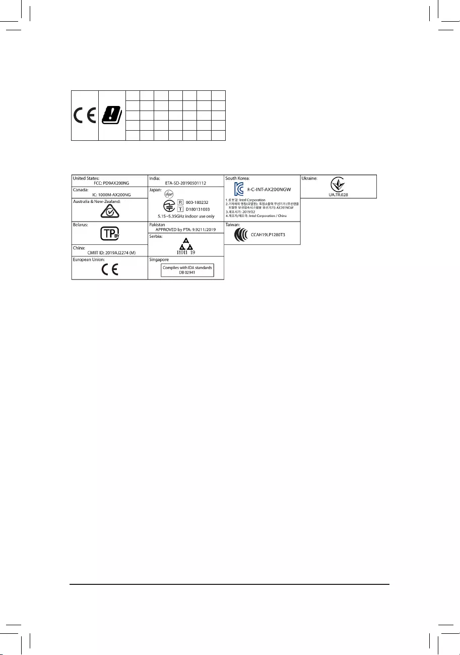
Korea Wireless Statement:
5.15 — 5.35 GHz 대역에서의 작동은 실내로。
Japan Wireless Statement:
5.15 GHz帯 ~ 5.35 GHz帯: 屋内のみの使用。
Taiwan NCC Wireless Statements / 無線設備警告聲明:
低功率電波輻射性電機管理辦法
第十二條: 經型式認證合格之低功率射頻電機,非經許可,公司、商號或使用者均不得擅自變更頻率、加大功率或變更原設
計之特性及功能。
第十四條: 低功率射頻電機之使用不得影響飛航安全及干擾合法通信;經發現有干擾現象時,應立即停用,並改善至無干擾
時方得繼續使用。前項合法通信,指依電信法規定作業之無線電通信。低功率射頻電機須忍受合法通信或工業、
科學及醫療用電波輻射性電機設備之干擾。
在5.25-5.35秭赫頻帶內操作之無線資訊傳輸設備,限於室內使用。
European Community Directive RED Directive Compliance Statement:
This equipment is suitable for home and ofce use in all the European Community Member States and EFTA Member States.
The low band 5.15 -5.35 GHz is for indoor use only for the countries listed in the table below:
AT BE BG CH CY CZ DE
DK EE EL ES FI FR HR
HU IE IS IT LI LT LU
LV MT NL PL PT RO SE
SI SK TR UK
Wireless module country approvals:
Wireless module model name: AX200NGW
Wireless module manufacturer: Intel® Corporation
— 49 —

— 50 —

— 51 —
Contact Us
GIGA-BYTE TECHNOLOGY CO., LTD.
Address: No.6, Baoqiang Rd., Xindian Dist., New Taipei City 231, Taiwan
TEL: +886-2-8912-4000, FAX: +886-2-8912-4005
Tech. and Non—Tech. Support (Sales/Marketing) : https://esupport.gigabyte.com
WEB address (English): https://www.gigabyte.com
WEB address (Chinese): https://www.gigabyte.com/tw
•GIGABYTE eSupport
To submit a technical or non-technical (Sales/Marketing) question, please link to:
https://esupport.gigabyte.com
— 52 —
|
Detail Specifications: 2251/2251099-b550_aorus_master.pdf file (06 Apr 2023) |
Accompanying Data:
Gigabyte B550 AORUS MASTER Motherboard PDF Operation & User’s Manual (Updated: Thursday 6th of April 2023 04:56:22 PM)
Rating: 4.7 (rated by 73 users)
Compatible devices: GA-34SGCM-S2, GA-H67A-D3H-B3 rev. 1.0, GA-6VXC7-4X-P, GA-MA790XT-UD4P, 6CX7 Series, G1.Assassin, GA-8SIML, GA-970A-DS3.
Recommended Documentation:
Text Version of Operation & User’s Manual
(Ocr-Read Summary of Contents, UPD: 06 April 2023)
-
52, Gigabyte B550 AORUS MASTER Contact Us GIGA-BYTE TECHNOLOGY CO., LTD. Address: No.6, Baoqiang Rd., Xindian Dist., New Taipei City 231, Taiwan TEL: +886-2-8912-4000, FAX: +886-2-8912-4005 Tech. and Non-Tech. Support (Sales/Marketing) : https://esupport.gigabyte.com WEB address (English): https://www.gigabyte.com WEB address (Chinese): https://www.gigabyte.com/tw • GIGABYTE eSupport To submit a techni…
-
44, Code Description 92 PCI Bus initialization is started. 93 PCI Bus hot plug initialization. 94 PCI Bus enumeration for detecting how many resources are requested. 95 Check PCI device requested resources. 96 Assign PCI device resources. 97 Console Output devices connect (ex. Monitor is lighted). 98 Console input devices connect (ex. PS2/USB keyboard/mouse are ac…
-
16, Gigabyte B550 AORUS MASTER DEBUG PORT G.QBOFM 131 2412 ATX 1/2) ATX_12V1/ATX_12V2/ATX (2×2, 2×4, 12V Power Connectors and 2×12 Main Power Connector) With the use of the power connector, the power supply can supply enough stable power to all the components on the motherboard. Before connecting the power connector, rst make sure the power supply is turned off and all devices are properly inst…
-
30, 2-5 Settings Platform Power & AC BACK Determines the state of the system after the return of power from an AC power loss. Memory The system returns to its last known awake state upon the return of the AC power. Always On The system is turned on upon the return of the AC power. Always Off The system stays off upon the return of the AC power. (Default) &…
-
8, Storage Interface 1 x M.2 connector (M2A_CPU), integrated in the CPU, supporting Socket 3, M key, type 2242/2280/22110 SSDs: — 3rd Generation AMD Ryzen ™ processors support SATA and PCIe 4.0 x4/x2 SSDs — New Generation AMD Ryzen ™ with Radeon ™ Graphics processors support SATA and PCIe 3.0 x4/x2 SSDs 2 x M.2 connectors (M2B_CPU/M2C_CPU), integrated in the CPU, su…
-
31, IO Ports & Initial Display Output Species the rst initiation of the monitor display from the installed PCI Express graphics card or the onboard graphics. IGD Video (Note) Sets the onboard graphics as the rst display. PCIe 1 Slot Sets the graphics card on the PCIEX16 slot as the rst display. (Default) PCIe 2 Slot …
-
11, Please visit GIGABYTE’s website for details on hardware installation. Dual Channel Memory Conguration This motherboard provides four memory sockets and supports Dual Channel Technology. After the memory is installed, the BIOS will automatically detect the specications and capacity of the memory. Enabling Dual Channel memory mode will double the o…
-
36, Gigabyte B550 AORUS MASTER 2-7 Boot & Boot Option Priorities Species the overall boot order from the available devices. Removable storage devices that support GPT format will be prexed with «UEFI:» string on the boot device list. To boot from an operating system that supports GPT partitioning, select the device prexed with «UEFI:» string. Or if you want to ins…
-
12, Due to CPU limitations, read the following guidelines before installing the memory in Dual Channel mode. 1. Dual Channel mode cannot be enabled if only one memory module is installed. 2. When enabling Dual Channel mode with two or four memory modules, it is recommended that memory of the same capacity, brand, speed, and chips be used. 1-5 Installing an Expansion…
-
6, Chapter 1 Hardware Installation 1-1 Installation Precautions The motherboard contains numerous delicate electronic circuits and components which can become damaged as a result of electrostatic discharge (ESD). Prior to installation, carefully read the user’s manual and follow these procedures: • Prior to installation, make sure the chassis is suitable for the m…
Recommended Instructions:
4500c, 4401, Eternus DX600 S3, 600cx


-
Telit Technical DocumentationWE310F5-I/PQuick Setup Guide1. Connect the micro-USB UART1 port to your system.2. Change the toggle switch position to Program.3. Download and unzip the Telit_Wifi_Image_Tool. For download information, see Resource Links.4. Open the Telit_Wifi_Image_Tool folder.5. Open the Telit_Wifi_Image_Tool application.6. Clic …
WE310F5-I 2
-
March 2019 UM2408 Rev 1 1/451UM2408User manualSTM32H7 Nucleo-144 boards (MB1363)IntroductionThe STM32H7 Nucleo-144 boards based on the MB1363 reference board (NUCLEO-H745ZI-Q, NUCLEO-H755ZI-Q) provide an affordable and flexible way for users to try out new concepts and build prototypes, by choosing from the various combinations of performance and power consumption features prov …
NUCLEO-H745ZI-Q 45
-
IQuick StartQuick StartThank you for purchasing the MSI® Z270I GAMING PRO CARBON AC motherboard. This Quick Start section provides demonstration diagrams about how to install your computer. Some of the installations also provide video demonstrations. Please link to the URL to watch it with the web browser on your phone or tablet. You may have even link to the URL by scanning the Q …
Z270I GAMING PRO CARBON AC 156