-
Contents
-
Table of Contents
-
Bookmarks
Quick Links
Operating Manual
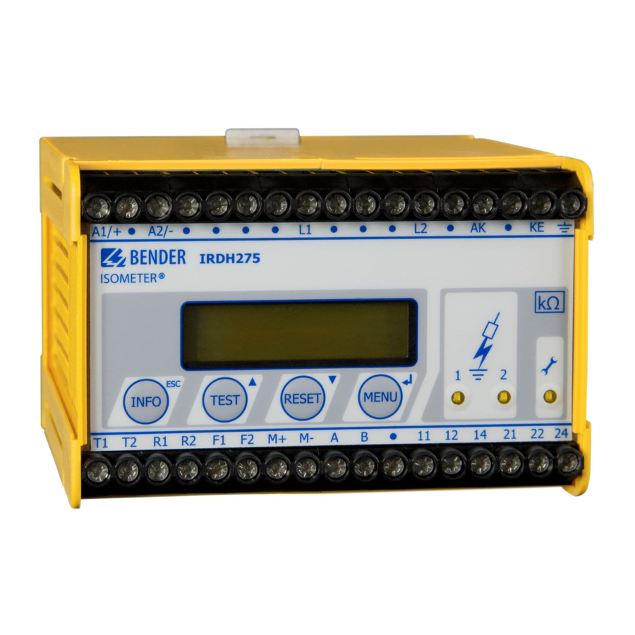
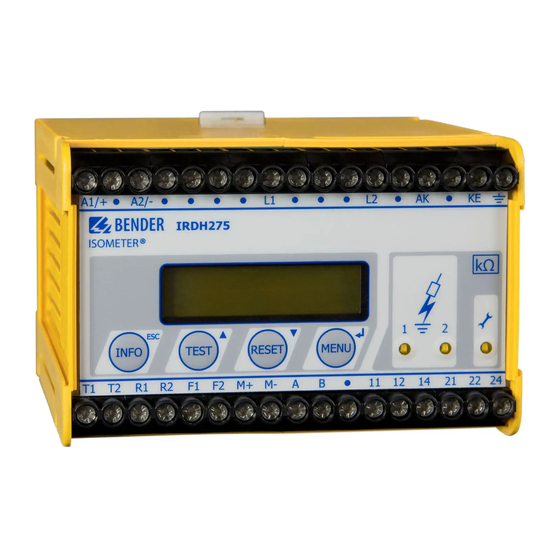
A-ISOMETER® IRDH275
IRDH275B
Insulation monitoring device for
IT AC systems with galvanically connected
rectifiers and converters
and for IT DC systems
Software version IRDH275: D160 V1.4
Software version IRDH275B: D159 V1.4
Power in electrical safety
TGH1361en/11.2009
Related Manuals for Bender A-ISOMETER IRDH275
Summary of Contents for Bender A-ISOMETER IRDH275
-
Page 1: Operating Manual
Operating Manual A-ISOMETER® IRDH275 IRDH275B Insulation monitoring device for IT AC systems with galvanically connected rectifiers and converters and for IT DC systems Software version IRDH275: D160 V1.4 Software version IRDH275B: D159 V1.4 Power in electrical safety TGH1361en/11.2009…
-
Page 2
Dipl.-Ing. W. Bender GmbH & Co. KG Londorfer Str. 65 • 35305 Grünberg • Germany Postfach 1161 • 35301 Grünberg • Germany Tel.: +49 6401-807-0 Fax: +49 6401-807-259 © Dipl.-Ing. W. Bender GmbH & Co. KG E-mail: info@bender-de.com All rights reserved. -
Page 3: Table Of Contents
Table of Contents 1. Safety information ……………… 7 Use for the intended purpose …………….7 Warranty and liability ………………… 7 1.2.1 Personnel ……………………8 1.2.2 About the operating manual …………….8 1.2.3 Hazards when handling the A-ISOMETER® IRDH275 ……..8 1.2.4 Inspection, transport and storage …………..
-
Page 4
Table of Contents 5. Operation and setting …………….31 Operating features and displays IRDH275(B) ……….31 5.1.1 Display in the standard mode …………….32 5.1.2 Display in the menu mode …………….. 32 5.1.3 Function keys ………………….33 Menu structure and menu mode ……….. 36 5.2.1 Diagram menu structure ……………… -
Page 5
Table of Contents Menu LANGUAGE …………….49 5.8.1 Setting the national language …………….49 5.8.2 Diagram Language ………………..49 Menu SERVICE ………………….50 5.10 Parameterization via Internet …………….50 6. Serial interfaces ………………51 RS485 interface with IsoData protocol (IRDH275) ……..51 RS485 interface with BMS protocol (IRDH275B) ……… -
Page 7: Safety Information
IT systems Any other use, or any use which goes beyond the foregoing, is deemed to be use other than for the intended purpose. The BENDER companies shall not be liable for any losses or damage arising therefrom.
-
Page 8: Personnel
1.2.2 About the operating manual This operating manual has been compiled with the greatest possible care. Nevertheless, errors and mistakes cannot be entirely ruled out. The BENDER companies assume no liability whatsoever for any injury to persons or dam- age to property which may be sustained as a result of faults or errors in this operating manual.
-
Page 9: Inspection, Transport And Storage
Inspect the dispatch packaging and equipment packaging for damage, and compare the contents of the package with the delivery documents. In the event of damage in transit, please inform the BENDER company immediate- The devices must only be stored in areas protected from dust, damp and spray or dripping water, and in which the specified storage temperatures are maintained.
-
Page 10: Directions For Installation
Safety information 1.4 Directions for installation Only one insulation monitoring device may be used in each intercon- nected IT system. When insulation or voltage test are to be carried out, the device shall be isolated from the system for the test period. The terminals and KE shall be connected by a separate wire to the pro- tective conductor (PE).
-
Page 11: Function
Memory with real-time clock to store all alarm messages with date and time stamp. BMS interface (BMS protocol) for data exchange with other Bender devices (RS485 electrically isolated). Internal disconnection of the A-ISOMETER from the IT system to be monitored (using a control signal;…
-
Page 12: Product Description
Suitable coupling devices are available to extend the nominal voltage range The IRDH275B can be used in combination with a control and indicating de- vice, e.g. PRC1470 version 2 or higher, on the BMS (BMS = Bender Measur- ing Device Interface) bus.
-
Page 13
0…400 µA or 0/4…20 mA (IRDH275B) at M+/M- are galvanically isolated. measuring principle «adaptive measuring pulse», a measuring principle developed by BENDER (European Patent: EP 0 654 673 B1). Self test A self test can be carried out manually using the TEST button or automatical- ly. -
Page 14
Device error x 2. Switch the supply voltage off and on error 3. Contact BENDER If the on/off switching of the supply voltage is not possible for technical reasons, a RESET of the process control can be carried out by pressing the «ESC“, «RESET“… -
Page 15: Additional Functions Irdh275B
Function 2.5 Additional functions IRDH275B Current output for external measuring instrument The current output of IRDH275B provides 0(4)…20 mA. The current output is galvanically isolated from the device electronics and the RS485 interface. The ISO SETUP menu, on page 43, allows to switch over between 0…20 mA and 4…20 mA.
-
Page 16
Function sulation monitoring is started. With this function, selective disconnection of an IRDH275 in interconnected IT systems can be carried out via auxiliary contacts of the respective coupling switch. One coupling switch each in a line-type or ring-type arrangement can deactivate a subsequent IRDH275. -
Page 17
Function ISOnet Function (COM SETUP) Select «ISOnet=ON» from the COM SETUP menu to activate this function. This function is a type of scanning function. The BMS Master activated via the ISOnet function controls the ISOnet slave devices via the BMS bus. Once an A-ISOMETER®… -
Page 18
Function TGH1361en/11.2009… -
Page 19: Commissioning Flow Chart (Threepart)
3. Commissioning flow chart (threepart) Due to limitations of space, the three-part flow chart begins on the next page. TGH1361en/11.2009…
-
Page 20
Commissioning of the A-ISOMETER® (1) Is the system to be monitored an The IRDH275 is not suitable for this unearthed system (IT system)? application( contact BENDER). U n is too high for direct Is the maximum nominal voltage connection. A coupling device… -
Page 21
Commissioning flow chart (threepart) Commissioning of the A-ISOMETER® (2) Connect the supply voltage U S The A-ISOMETER carries out a self test. The display indicates the insulation value after finishing Connect the voltage U n of the the measurement. IT system to be monitored Only IRDH275B: set the clock Shall the basic setting… -
Page 22
Commissioning flow chart (threepart) Commissioning of the A-ISOMETER® (3) In order to check the proper connection, a functional test using a suitable resistance is to be carried out. Size of the resistance: 50% of the preset response value Alarm 2. Check the connecting leads ! Do both alarm LEDs light up? Is voltage Un applied to the… -
Page 23: Connection
4. Connection 4.1 Wiring Connect the terminals A1/+ and A2/- to the supply voltage U in accordance with IEC 60364-4-43. The connections to the supply voltage shall be provid- ed with protective devices to afford protection in the event of a short circuit (a 6 A fuse is recommended).
-
Page 24
Connection 3 AC — System AC — System 3/N AC — System DC — System A1/+ A2/- IRDH275(B) T1 T2 R1 R2 F1 F2 M+ M- A B 11 12 14 21 22 24 TGH1361en/11.2009… -
Page 25
Connection Legend to wiring diagram: 1 Supply voltage U (see nameplate) via 6 A fuse 2, 3 Connection to the 3AC system to be monitored: connect terminals L1, L2 to neutral conductor N or terminals L1, L2 to conductor L1, L2 4 Connection to the AC system to be monitored: connect terminals L1, L2 to conductor L1, L2 5 Connection to the DC system to be monitored:… -
Page 26: Wiring Diagrams With Coupling Devices
Connection 4.2 Wiring diagrams with coupling devices Please observe the settings in the «ISO ADVANCED AGH“ menu ! Adapt the settings to the coupling device to be used. 4.2.1 Connection with AGH150W-4 Connected to the A-ISOMETER® this coupling device extends the nominal voltage range to DC 1760 V in DC systems.
-
Page 27: Connection With Agh520S
Connection 4.2.2 Connection with AGH520S Connected to the A-ISOMETER® this coupling device extends the nominal voltage range to AC 7200 V in pure AC systems. In case of 3 AC systems, Pin 2 of AGH520S is to be connected to L1, in case of 3/N/AC systems, Pin 2 is to be connected to the N-conductor.
-
Page 28: Connection With Agh204S-4
Connection 4.2.3 Connection with AGH204S-4 This coupling device extends the nominal voltage range of A-ISOMETERs® used in AC systems including rectifiers. AK160 AK80 IRDH275 AGH204S-4 = 3AC 0..1650 V (DC max. 1000 V) 1 without rectifiers = 3AC 0..1300 V (max. AC voltage; max. DC voltage 2 with rectifiers after rectifiers in intermediate circuits of frequency con- verters:1840 V)
-
Page 29
Connection In case of current-controlled intermediate circuits of frequency converters, higher DC voltages are to be expected. The given voltage values for AC/DC systems take into account values found by previous experience (factor 1.414 between DC voltage and AC voltage). The maximum DC voltage in case of insulation faults in the DC part of the IT system, for example converter intermediate circuit, is DC 1840 V. -
Page 30
Connection TGH1361en/11.2009… -
Page 31: Operation And Setting
5. Operation and setting 5.1 Operating features and displays IRDH275(B) A-ISOMETER® IRDH275 * * * I T — S Y S T E M * * * * R = 0 8 6 k W INFO TEST RESET MENU 1 INFO key: to query standard information / ESC key: back (menu function), confirmation parameter change 2 TEST button: to call up the self test/ Up key: parameter change, moving up in the menu…
-
Page 32: Display In The Standard Mode
Operation and setting 5.1.1 Display in the standard mode I n s u l a t i o n F a u l t R s = 0 1 1 k 1 Indication of the insulation resistance in kΩ 2 Additional information about the insulation resistance: «+»…
-
Page 33: Function Keys
Setup status (for details refer to the table of the status numbers on page 68) COM-Setup (IRDH275 bus address) Please have the details above on hand if you have a problem and if you con- tact BENDER for technical questions. Activating the TEST button starts the A-ISOMETER® self test. TEST…
-
Page 34
Operation and setting For controlling the menu system, the arrow keys, the ENTER key and the ESC key are used: Arrow up key: Moving up in the menu, increasing a parameter TEST Arrow down key: Moving down in the menu, reducing a parameter RESET ENTER key Selecting a menu item or sub menu item, confirming or storing a… -
Page 35
Operation and setting TGH1361en/11.2009… -
Page 36: Menu Structure And Menu Mode
Operation and setting 5.2 Menu structure and menu mode Switchover to the menu mode After pressing the MENU key, you can change from the standard mode to the menu mode. From the menu mode you can link to the different sub menus. Navigation within the menu Select the desired menu item using the UP/DOWN keys.
-
Page 37: Diagram Menu Structure
Operation and setting 5.2.1 Diagram menu structure *** IT-SYSTEM *** MENU R >010 MW 1. EXIT 2. HISTORY INFO 3. ISO SETUP 4. ISO ADVANCED 5. COM SETUP 6. PASSWORD 7. LANGUAGE 8. SERVICE HISTORY INFO ISO SETUP ISO ADVANCED COM SETUP PASSWORD LANGUAGE…
-
Page 38: Menu History Info (Irdh275B)
Operation and setting 5.3 Menu HISTORY INFO (IRDH275B) 99 events with date and time stamp can be stored in the memory database. The database is designed as a ring memory, i.e. the eldest entry is overwrit- ten. Data is written into a non-volatile memory and therefore provides pro- tection against voltage failure.
-
Page 39: Diagram History Info (Irdh275B)
Operation and setting 5.3.1 Diagram HISTORY INFO (IRDH275B) *** IT-SYSTEM *** R >010 MW 1. EXIT 2. HISTORY INFO 3. ISO SETUP 4. ISO ADVANCED 5. COM SETUP 6. PASSWORD 7. LANGUAGE 8. SERVICE Nr.: 01 #Nr: 08 Power on Nr.: 01 #Nr: 08 Clear all: off Nr.: 01 #Nr: 08…
-
Page 40: Menu Iso Setup: Setting Of The Basic A-Isometer® Functions
Operation and setting 5.4 Menu ISO SETUP: Setting of the basic A-ISOMETER® functions All alarm functions such as Alarm 1 and Alarm 2 (prewarning and main alarm), the operating principle of the alarm relays K1 and K2 (N.O = N/O operation, N.C = N/C operation), the fault storage behaviour and a selection of two current output ranges are set in this menu.
-
Page 41
Operation and setting Diagram ISO SETUP *** IT-SYSTEM *** R >010 MW 1. EXIT 2. HISTORY INFO 3. ISO SETUP 4. ISO ADVANCED 5. COM SETUP 6. PASSWORD 7. LANGUAGE 8. SERVICE 1. Exit 2. Alarm1: 100 KW Alarm1 : 100 KW 3. -
Page 42: Memory Setting (On/Off)
Operation and setting During the automatic self test, the alarm relays are not switched over. When a device fault occurs at the A-ISOMETER®, the relay K2 will au- tomatically be activated as a device fault relay. 5.4.3 Memory setting (on/off) Memory: on = Fault memory is activated The device must be reset with the RESET button after…
-
Page 43: Menu Iso Advanced: Setting Of The Extended Functions
Operation and setting 5.5 Menu ISO ADVANCED: Setting of the extended functions 5.5.1 External coupling devices (AGH: no) Basic setting «no», when no coupling device is used (factory setting). AGH: 204 AK80 Terminal AK of the IRDH275 is connected to terminal AK80 of the AGH204S-4.
-
Page 44: Adaptation To The System Leakage Capacitance (Cemax : 150 Μf)
Operation and setting 5.5.2 Adaptation to the system leakage capacitance (Cemax: 150 µ This menu allows to adapt the A-ISOMETER® to the maximum system leak- age capacitance (max. 500 µF). Please note that the basic measuring time will be increased to approximately 10 seconds when the setting is C = 500 µF.
-
Page 45: Diagram Iso Advanced
Operation and setting 5.5.8 Diagram ISO ADVANCED *** IT-SYSTEM *** R >010 MW 1. EXIT 2. HISTORY INFO 3. ISO SETUP 4. ISO ADVANCED 5. COM SETUP 6. PASSWORD 7. LANGUAGE 8. SERVICE 150 AK160 204 AK160 520S 204 AK80 1.
-
Page 46: Menu Com Setup: Setting The Bms Interface
Operation and setting 5.6 Menu COM SETUP: Setting the BMS interface 5.6.1 Bus address „Addr:“ (IRDH275B) This menu item is used to set the BMS bus address of the IRDH275. Since there are several A-ISOMETERs in one system, take care that the bus address is not assigned twice.
-
Page 47: Diagram Com Setup (Irdh275B)
Operation and setting 5.6.4 Diagram COM SETUP (IRDH275B) *** IT-SYSTEM *** R >010 MW 1. EXIT 2. HISTORY INFO 3. ISO SETUP 4. ISO ADVANCED 5. COM SETUP 6. PASSWORD 7. LANGUAGE 8. SERVICE 1. Exit 2. Addr: 003 Addr : 003 3.
-
Page 48: Menu Password
Operation and setting 5.7 Menu PASSWORD 5.7.1 Activating and setting the password This menu can be used to activate a «Password» query. This protects the A- ISOMETER® against unauthorized settings and modifications. The desired password (menu item 2. Password: xxx) can be set with the UP/DOWN keys and confirmed with the ENTER key.
-
Page 49: Menu Language
Operation and setting 5.8 Menu LANGUAGE 5.8.1 Setting the national language The menu item «Language» allows fault messages of the A-ISOMETER® to be set to different languages. There is the choice of German and English. The device menu is not influenced by the language selection. 5.8.2 Diagram Language *** IT-SYSTEM *** R >010 M…
-
Page 50: Menu Service
Operation and setting 5.9 Menu SERVICE This menu item is provided for the BENDER service personnel and is pro- tected by a password against erroneous settings. It is intended to provide fast fault clearance by qualified experts in the event of a device error.
-
Page 51: Serial Interfaces
6. Serial interfaces The A-ISOMETERs® IRDH275 and IRDH275B have differently designed se- rial interfaces. -RS485 and IsoData protocol IRDH275 -galvanically isolated -ASCII, unidirectional -RS485 and BMS protocol IRDH275B -galvanically isolated -ASCII, bidirectional 6.1 RS485 interface with IsoData protocol (IRDH275) Data transmission is continuously carried out and can neither be interrupted by the data slave station nor be influenced in any other way.
-
Page 52
Serial interfaces Start US= Unit separator Response value Measuring value Alarm1 e.g. 60 kW e.g. 128 kW = No alarm Response value = Alarm1 Alarm2 e.g. 120 kW = Alarm2 = Alarm1/2 = K1 off, K2 off = AC fault = K1 on, K2 off = DC- fault = K1 off, K2 on… -
Page 53: Rs485 Interface With Bms Protocol (Irdh275B)
Serial interfaces 6.2 RS485 interface with BMS protocol (IRDH275B) The RS485 interface galvanically isolated from the device electronics and cur- rent output serves as a physical transmission medium for the BMS protocol. If several IRDH275B or other bus-capable devices are interconnected in a network via the BMS bus, the BMS bus must be terminated at both ends with a 120 Ω…
-
Page 54: Topology Rs485 Network (Irdh275B)
(e.g. J-Y(St)Y 2 x 0.6), screen on one side connected to earth (PE). Connection to the terminals A and B. The number of bus nodes is restricted to 32 devices. When more devices are to be connected, Bender recommends to use an RS485 repeater DI1. TGH1361en/11.2009…
-
Page 55: Bms Protocol (Irdh275B)
Serial interfaces 6.4 BMS protocol (IRDH275B) This protocol is an essential part of the Bender Measuring Device Interface. Data transmission generally makes use of ASCII characters. Interface data are: Baud rate:9600 baud transmission:1 start bit, 7 data bits, 1 parity bit, 1 stop bit (1, 7, E, 1)
-
Page 56: Bms Slave
Serial interfaces 6.4.2 BMS Slave All IRDH275B are factory set to slave mode (address 3). In a BMS network, one address must be selected from the address range 2…30 for each slave. There may be no gaps of more than five subsequent addresses, so that all slaves can be scanned by the Master.
-
Page 57: Commissioning Of An Rs485 Network With Bms Protocol
Serial interfaces The following table gives an overview about essential alarm messages and the assignment of the messages indicated on the display or operator panels, e.g. PRC1470. Message Meaning Channel Insulation Fault Insulation resistance < setting Alarm 1 Insulation Fault Insulation resistance <…
-
Page 58
Serial interfaces BMS-bus address ranges Addresses* Device Meaning There is no device with address 0 ! Information sent to address 0 applies to all devices connected to the interface (broadcast) 1 PRC1470 Control and indicating device IRDH275B/ 1…30 Insulation monitoring device 375B/575 1…30 FTC470… -
Page 59: Technical Data Irdh275(B)
7. Technical data IRDH275(B) 7.1 Data in tabular form The values marked with * are absolute values Insulation coordination acc. to IEC 60664-1 Rated voltage ……………………..AC 800 V Rated impulse voltage/pollution degree………………8 kV / 3 Voltage ranges IRDH275..: Nominal voltage range U …………….1AC / 3 (N) AC 0…793 V* Nominal frequency f (for f<50 Hz see characteristic curve on page 64) ……
-
Page 60
Technical data IRDH275(B) …………….≤ DC 1200 V Permissible extraneous DC voltage U …………….≤ 500 μF Permissible system leakage capacitance C Factory setting ……………………..150 μF Displays Display, illuminated………………….two-line display Characters (number of characters) ………………..2 x 16 Ω… -
Page 61: General Data
Technical data IRDH275(B) General data EMC immunity ……………………. acc. to EN 61326 EMC emission ……………………acc. to EN 61326 Shock resistance IEC 60068-2-27 (device in operation) …………15 g / 11 ms Bumping IEC 60068-2-29 (during transport)…………….. 40 g / 6 ms Vibration resistance IEC 60068-2-6 (device in operation)……….1 g / 10…150 Hz Vibration resistance IEC 60068-2-6 (during transport) ……….2 g / 10…150 Hz Ambient temperature (during operation) …………….-10 °C…+55 °C…
-
Page 62: Standards And Approvals
Technical data IRDH275(B) 7.2 Standards and approvals The A-ISOMETER® was designed under consideration of the following standards: — DIN EN 61557-8 (VDE 0413-8):1998-05 — EN 61557-8:1997-03 — IEC 61557-8:1997-02 — EN 61326 — DIN EN 60664-1 (VDE 0110-1):2003-11 — DIN EN 60664-3 (VDE 0110-3):2003-09 — ASTM F1669M-96(2002) — ASTM F1207M-96(2002) TGH1361en/11.2009…
-
Page 63: Characteristic Curves
Technical data IRDH275(B) 7.3 Characteristic curves A-ISOMETER® response times in relation to system leakage capacitances of: = 1…500 µF, U = 0…793 V / 50 Hz 1000 ≤ Ω 10 M ≥ Ω 1000 [μF] TGH1361en/11.2009…
-
Page 64
Technical data IRDH275(B) Max. AC voltage between the IT system and earth in the frequency range <50 Hz 10000 AGH520S AGH204S-4 1000 IRDH275 [Hz] TGH1361en/11.2009… -
Page 65
Technical data IRDH275(B) Current output 0…400 μA (only IRDH275) [ kW] [ mA] 400 mA x 120 kW — 120 kW = Insulation fault in kΩ I = Current output in mA TGH1361en/11.2009… -
Page 66
Technical data IRDH275(B) Current output 0…20 mA (IRDH275B) [kW] 10 000 1000 I [mA] 20 mA x 120 kW — 120 kW = Insulation fault in kΩ = Current output in mA TGH1361en/11.2009… -
Page 67
Technical data IRDH275(B) Current output 4…20 mA (IRDH275B) [kW] 10 000 1000 I [mA] 16 mA x 120 kW — 120 kW I — 4 mA = Insulation fault in kΩ = Current output in mA TGH1361en/11.2009… -
Page 68
Technical data IRDH275(B) Status number TGH1361en/11.2009… -
Page 69
Technical data IRDH275(B) Dimension diagram enclosure IRDH275(B) ø 4,5 mm DIN rail mounting according to IEC 60715 Screw mounting by means of a plug-in trapezoidal support Order No.: 990056 (Option W) TGH1361en/11.2009… -
Page 70: Ordering Details
Technical data IRDH275(B) 7.4 Ordering details 7.4.1 A-ISOMETER® Nominal voltage Supply voltage Type Art.-No. 3(N)AC 0…793 V AC 88…264 V IRDH275-435 B 9106 5100 DC 0…650 V DC 77…286 V IRDH275W-435 „ „ B 9106 5100W IRDH275B-435 „ „ B 9106 5101 IRDH275BW-435 „…
-
Page 71: Coupling Devices
Technical data IRDH275(B) 7.4.2 Coupling devices Nominal voltage Art. No. Type range U AGH204S-4 AC 0…1650 V B 914 013 AGH520S AC 0…7200 V B 913 033 AGH150W-4 DC 0…1760 V B 9801 8006 7.4.3 Measuring instruments Type Measuring range Dimensions Art.
-
Page 72
Technical data IRDH275(B) TGH1361en/11.2009… -
Page 73
Alarm messages Display in the menu mode Approvals Display in the standard mode Automatic self test Explanations of symbols and warnings Bender Measuring Device Interface External coupling devices BMS bus External RESET button — correct arrangement External TEST button — wrong arrangement… -
Page 74
INDEX Setting the response values Alarm 1 and Alarm 2 Measuring instruments Setting the system leakage capacitance Memory database Standards Menu Status number — COM SETUP — HISTORY INFO — ISO ADVANCED — ISO SETUP Technical data IRDH275 — LANGUAGE Terminating resistor — PASSWORD TEST button… -
Page 76
Dipl.-Ing. W. Bender GmbH & Co. KG Londorfer Str. 65 • 35305 Grünberg • Germany Postfach 1161 • 35301 Grünberg • Germany Tel.: +49 6401-807-0 Fax: +49 6401-807-259 E-Mail: info@bender-de.com Web: http://www.bender-de.com…
A -ISOMETЕR® IRDH575

Контроль изоляции в изолированных от земли (IT) сетях переменного, постоянного тока, смешанного типа.
Система поиска повреждений изоляции.
РУКОВОДСТВО ПО ЭКСПЛУАТАЦИИ TGH1 364/03.2003
![]()


![]()
Оглавление
| 1. Указания по безопасности
1.1 Назначение 1.2 Гарантия и ответственность 1.2.1 Персонал 1.2.2 О руководстве по эксплуатации 1.2.3 Опасности при работе с прибором IRDH 575 1.2.4 Контроль, транспортировка и складирование 1.2.5 Примечания 1.3 Символы и указания 1.4 Указания по монтажу
2.1 Общие характеристики 2.2 Функции прибора А-ISOMETЕR
2.5.1 Часы реального времени 2.5.2 Поиск повреждений изоляции 2.5.3 Информационная сеть 2.5.4 Функциональный вход F1 / F 2 2.5.5 Автотестирование (самодиагностика)
EDS – общая информация
4.1 Схема подключения
5.1.2 Дисплей в режиме «Menu» |
7 7 7 8 8 8 8 9 9 10 11 11 11 12 12 12 13 13 13 14 15 28 29 29 |
![]()
| 5.1.3 Клавиши управления
5.2 Структура меню 5.2.1 Схема структуры меню 5.3 Меню HISTORY INFO (регистрация информации) 5.3.1 Схема HISTORY INFO
Настройка основных функций прибора A-ISOMETER 5.4.1 Уставки Alarm1 и Alarm2
5.4.3 Принцип работы сигнальных реле 5.4.4 Настройка памяти 5.4.5 Выходной ток 5.5 Меню ISO ADVANCED: настройка расширенных функций 5.5.1 Внешние адаптеры (AGH:no=заводская установка) 5.5.2 Подстройка по емкости относительно земли (Семаx :150мкф=заводская установка)
(Measure: AMP=заводская установка)
(Аutotest:24 h=заводская установка) 5.5.5 Часы реального времени (Clock) 5.5.6 Дата (Date) 5.5.7 Проверка (Test) 5.5.8 Схема ISO ADVANCED
5.6.1 EDS auto (on/off/pos/1cycle) 5.6.2 Схема EDS-SETUP 5.6.3 Система DC / 1AC / 3AC 5.6.4 макс. пульс тока 1 / 2,5 / 10 /25 / 50 мА
5.7.1 EDS – Монитор 5.7.2 EDS — Тест 5.7.3 EDS Reset 5.7.4 Схема EDS ADVANCED 5.7.5 Указания к пунктам меню Relay, Memory и n-peak 5.7.6 Relay 5.7.7 Memory 5.7.8 CT-Setup 5.7.9 n-peak 5.8 Mеню Com Setup: настройка BMS-интерфейса 5.8.1 Адрес шины (Addr: ) 5.8.2 ISO-монитор 5.8.3 схема Com Setup 5.9 Mеню PASSWORD (пароль) |
29
31 32 33 34 35 35 35 37 38 39 39 39 39 39 40 41 41 42 43 43 45 45 45 45 46 47 47 47 47 48 49 49 49 50 51 |
![]()
| 5.9.1 Установка пароля и его активизация
5.9.2 Схема PASSWORD 5.10 Mеню Language (язык) 5.10.1 Выбор языка 5.10.2 Схема Language (язык) 5.11 Mеню SERVICE 6.2 Топология 6.2.1 Правильное подключение 6.2.2 Неправильное подключение 6.2.3 Проводка 6.3 Интерфейс измерительного прибора фирмы «Bender GmbH» (BMS) 6.3.1 BMS- Master 6.3.2 BMS-Slave 6.3.3 Режим работы с приборами EDS47х 6.3.4 Пуск сети BMS 7.2 Нормы и стандарты 7.3 Характеристики 7.4 Данные для заказа 7.4.1 Стандартное исполнение 7.4.2 Измерительный инструмент 7.4.3 Шильдик прибора |
51
51 52 52 52 53 55 55 55 55 57 57 59 61 67 68 82 82 82 83 |
![]()
У![]() казания по безопасности
казания по безопасности

- Указания по безопасности
- Назначение
Прибор A-ISOMETER® предназначен:
- Для контроля сопротивления изоляции в IT-сетях, а также
- Для обнаружения повреждений изоляции с помощью дополнительных приборов, подключаемых посредством RS485-интерфейса..
Недопустимо другое применение прибора, не соответствующее вышеуказанному назначению.
За ущерб, возможный вследствие применения прибора не по назначению, фирма BENDER GmbH ответственности не несет.
Применение согласно назначению означает также:
- Соблюдение всех указаний данного руководства по эксплуатации и
- Соблюдение режимов обслуживания и контроля прибора
Взаимоотношения между производителем и потребителем основаны на «Общих условиях продажи и поставки продукции» нашего предприятия, предоставляемых в распоряжение покупателя прибора самое позднее в момент заключения контракта о покупке.
1.2 Гарантия и ответственность
Гарантийные претензии за понесённый материальный или человеческий ущерб не принимаются в тех случаях, если ущерб имел место вследствие следующих причин:
- применение прибора A-ISOMETER® не по назначению.
- неправильные монтаж и пуск в эксплуатацию, эксплуатация и техническое обслуживание прибора A-ISOMETER®.
- несоблюдение требований Руководства по эксплуатации по транспортировке, пуску в эксплуатацию, последующей эксплуатации и техническому обслуживанию прибора A-ISOMETER®.
- несанкционированные конструктивные изменения
прибора A-ISOMETER®.
- эксплуатация прибора в условиях, не соответствующих техническим требованиям.
- ненадлежащим образом проведенные ремонтные работы и применение запасных частей, не рекомендованных изготовителем.
- аварии, вызванные воздействием инородных тел и экстремальным внешним воздействием.
- монтаж и установка прибора в комбинации с другими приборами, не рекомендованной изготовителем.
Данное Руководство по эксплуатации, особенно в части безопасности, является обязательным для исполнения для всего персонала, работающего с прибором
A-ISOMETER®. Кроме того, также обязательным является соблюдение всех предписаний и норм безопасности, действующих на объекте, на котором применен данный прибор.
У![]() казания по безопасности
казания по безопасности
1.2.1 Персонал
С прибором A-ISOMETER® имеет право работать только персонал, имеющий соответствующую квалификацию.
Квалифицированным считается персонал, имеющий навыки монтажа, пуска в эксплуатацию и обслуживания прибора и прошедший специальное обучение.
Персонал должен быть ознакомлен с указаниями по безопасности и соответствующими предупреждениями данного Руководства по эксплуатации.
1.2.2 О руководстве по эксплуатации
Данное руководство создавалось с особой тщательностью. Тем не менее, невозможно абсолютно исключить разного рода ошибки и неточности. Фирма BENDER GmbH не берет на себя ответственность за возможный людской или материальный ущерб, вызванный ошибками или неточностями данного руководства по эксплуатации.
1.2.3 Опасности при работе с прибором IRDH575
Прибор A-ISOMETER® IRDH575 изготовлен по последнему слову техники и в соответствии с современными общепринятыми нормами безопасности.
Тем не менее, при эксплуатации прибора возможно возникновение ситуаций, опасных для здоровья или жизни пользователя или третьего лица, или наносящих вред самому прибору или его техническим параметрам.
A-ISOMETER® следует использовать только
- для применения по назначению
- в безупречном по условиям безопасности техническом состоянии.
Неисправности, которые могут ухудшить условия безопасности, должны быть немедленно устранены.
Изменения конструкции прибора или применение запасных частей и устройств, не от изготовителя или не рекомендованных изготовителем к применению, могут явиться причиной возгораний, электротравм.
Некомпетентный персонал не должен иметь доступа к прибору A-ISOMETER®.
Таблички и плакаты с инструкциями по эксплуатации должны быть хорошо видимы и легко читаемы. Повреждённые или нечитаемые надписи должны быть немедленно заменены.
1.2.4 Контроль, транспортировка и складирование
Необходимо проверять тару и упаковку приборов на предмет повреждения и сравнивать содержание поставки с сопроводительной накладной. В случае установления факта повреждения приборов при транспортировке следует незамедлительно уведомить фирму W. BENDER GmbH.
Хранить приборы допустимо только в помещении при заданной температуре и обеспечивающем защиту приборов от пыли, влаги, брызг и капель воды.
У![]() казания по безопасности
казания по безопасности
1.2.5 Примечания
На правильное подключение к источнику питания!
Перед проведением испытания изоляции и напряжения приборы A-ISOMETER® должны быть отключены от сети.
Перед пуском в эксплуатацию для проверки правильности подключения прибора необходимо провести тест прибора на работоспособность.
Необходимо проверить, соответствуют ли первоначальные заводские настройки прибора параметрам сети.
Дети и посторонние лица не должны иметь доступа к прибору
A-ISOMETER®.
Цифровой мультиметр Gardner Bender GDT-311

ФУНКЦИИ СЧЕТЧИКА

ФУНКЦИИ (Рисунок 1)
- Цифровой дисплей на 2000 отсчетов
- 14 позиции
- Вольт переменного тока
- Вольт постоянного тока 1
- Сопротивление
- Выбор выключенного набора
- Индикатор низкого заряда батареи
- Общий входной разъем
- Положительный входной разъем
ФУНКЦИИ СЧЕТЧИКА
| Тип счетчика: | Вручную |
| Функции: | 3 |
| Диапазоны: | 12 |
| Количество дисплеев: | 2000 |
| Входное сопротивление: | 10 Мег Ом |
| Диапазоны переменного напряжения: | 200/500 (2.5% + 5 цифр) |
| Диапазоны постоянного напряжения | 200м / 2000м / 20/200/600 ± (1.2% + 2 градуса) |
| Диапазоны сопротивления: | 200/2000 / 20к / 200к / 2000к ± (1.5% + 2 ед.) |
| Условия эксплуатации Использование в помещении | |
| Рабочая температура: | 0 ° C — 40 ° C |
| Температура хранения: | -10 ° С — 50 ° С |
| Относительная влажность: | 0% — 75% относительной влажности (0 ° C — 31 ° C) 0% — 50% относительной влажности (31 ° C — 40 ° C) |
| Высота над уровнем моря: | До 2000m |
| Степень защиты от проникновения: | IP40 |
| Степень загрязнения: | 2 |
| Элементы питания: | 9 вольт |
| Срок службы батареи: | 100 часов с угольно-цинковыми элементами, 200 часов с щелочными элементами в нормальных условиях. |
| Индикация превышения диапазона: | Три младшие значащие цифры остаются пустыми, а число «1» отображается слева, когда вход превышает допустимый диапазон. |
| Индикация полярности: | Отображается отрицательно, подразумевается положительное |
| Размер (ДхШхВ): | 5.51 «х» х 2.83 1.26 « |
| Вес: | Приблизительно 110 г (без батарей) |
| Тип тестового провода: | ETL, cETL, CE, CAT III 600 В, 1 А  |
| Агентские разрешения: | ETL, CE, CAT III 600 В |
Примечание: погрешность указана на один год при 23 ° C ± 3 ° C rah <70%.
ПРОЧИТАЙТЕ Вначале: ВАЖНАЯ ИНФОРМАЦИЯ ПО БЕЗОПАСНОСТИ

![]() Перед использованием мультиметра внимательно прочтите это руководство оператора. Это руководство предназначено для предоставления основной информации об этом измерителе и для описания общих процедур тестирования, которые могут быть выполнены с этим устройством. Многие типы приборов, механизмов и других электрических цепей не рассматриваются в этом руководстве и должны выполняться опытными специалистами по обслуживанию.
Перед использованием мультиметра внимательно прочтите это руководство оператора. Это руководство предназначено для предоставления основной информации об этом измерителе и для описания общих процедур тестирования, которые могут быть выполнены с этим устройством. Многие типы приборов, механизмов и других электрических цепей не рассматриваются в этом руководстве и должны выполняться опытными специалистами по обслуживанию.
Маркировка « ![]() »На оборудовании означает« Осторожно », опасность поражения электрическим током.
»На оборудовании означает« Осторожно », опасность поражения электрическим током.
Маркировка « ![]() »На оборудовании означает« Осторожно », опасность опасности.
»На оборудовании означает« Осторожно », опасность опасности.
Маркировка « ![]() ”На оборудовании обозначает клемму функционального заземления.
”На оборудовании обозначает клемму функционального заземления.
Маркировка « ![]() »На оборудовании представляет Оборудование, защищенное ДВОЙНОЙ ИЗОЛЯЦИЕЙ или УСИЛЕННОЙ ИЗОЛЯЦИЕЙ.
»На оборудовании представляет Оборудование, защищенное ДВОЙНОЙ ИЗОЛЯЦИЕЙ или УСИЛЕННОЙ ИЗОЛЯЦИЕЙ.
Будьте предельно осторожны при использовании этого мультиметра. Неправильное использование этого глюкометра может привести к серьезному материальному ущербу, серьезным травмам или смерти. Следуйте всем инструкциям и предложениям, содержащимся в данном руководстве оператора, а также соблюдайте обычные меры предосторожности при работе с электричеством. Не используйте этот глюкометр, если вы не знакомы с электрическими цепями и надлежащими процедурами тестирования.
МЕРЫ БЕЗОПАСНОСТИ
- Это руководство по эксплуатации содержит предупреждения и правила безопасности, которые должен соблюдать пользователь, чтобы обеспечить безопасную работу прибора и сохранить его в безопасном состоянии.
- Перед использованием прибора прочтите и усвойте инструкции, содержащиеся в данном руководстве.
- Держите руководство под рукой, чтобы при необходимости можно было быстро найти его.
- Прибор следует использовать только по прямому назначению.
- Поймите и соблюдайте все инструкции по технике безопасности, содержащиеся в руководстве.
- Очень важно соблюдать все инструкции по технике безопасности.
- Несоблюдение инструкций по технике безопасности может привести к травмам или повреждению прибора.
Символ ![]() Указание на приборе означает, что пользователь должен обратиться к соответствующим частям в руководстве для безопасной эксплуатации прибора. Обязательно прочтите инструкции везде, где в руководстве есть символ.
Указание на приборе означает, что пользователь должен обратиться к соответствующим частям в руководстве для безопасной эксплуатации прибора. Обязательно прочтите инструкции везде, где в руководстве есть символ.
![]() ОПАСНО!
ОПАСНО!
- Никогда не производите измерения в цепи, в которой объемtagе существует более 1000 В.
- Не превышайте рейтинг CAT измерительного устройства.
- Не пытайтесь проводить измерения в присутствии легковоспламеняющихся газов.
- Использование прибора может вызвать искрение, которое может привести к взрыву.
- Никогда не используйте инструмент, если его поверхность или ваша рука влажные.
- Не превышайте максимально допустимый вход любого диапазона измерения.
- Никогда не открывайте крышку батарейного отсека во время измерения.
- Прибор следует использовать только по назначению или в условиях. Использование не по назначению может привести к повреждению прибора или серьезным травмам.
![]() ПРЕДУПРЕЖДЕНИЕ
ПРЕДУПРЕЖДЕНИЕ
- Никогда не пытайтесь выполнить какие-либо измерения, если отмечены какие-либо аномальные условия, такие как сломанный корпус, треснувшие измерительные провода и оголенные металлические части.
- Не поворачивайте переключатель выбора функций при подключенных измерительных проводах, подключенных к проверяемой цепи.
- Не устанавливайте запасные части и не вносите никаких изменений в прибор.
- Верните прибор своему дистрибьютору для ремонта или повторной калибровки.
- Не пытайтесь заменить батарейки, если поверхность инструмента мокрая.
- Всегда выключайте прибор, прежде чем открывать крышку батарейного отсека для замены батарейки.
![]() ВНИМАНИЕ!
ВНИМАНИЕ!
- Перед началом измерения установите переключатель функций в соответствующее положение.
- Плотно вставьте тестовый провод
- Отсоедините щупы от прибора для измерения тока.
- Не подвергайте инструмент воздействию прямых солнечных лучей, высоких температур, влажности или капель росы.
- Обязательно выключите прибор после использования.
Если прибор не будет использоваться в течение длительного времени, поместите его на хранение после извлечения батарей. - Используйте только мягкую ткань dampс водой или нейтральным моющим средством для очистки счетчика. Не используйте абразивные материалы, растворители или агрессивные химикаты. Дайте полностью высохнуть перед использованием.
ИНСТРУКЦИЯ ПО ЭКСПЛУАТАЦИИ НАСТРОЙКИ ДИСКА

НАПРЯЖЕНИЕ ПЕРЕМЕННОГО ТОКА
Есть два диапазона измерения переменного напряжения.tage: 200 В и 500 В. Для более точных измерений при напряжении ниже 200 В используйте настройку 200 Вольт.
- Подключите черный измерительный провод к клемме «COM», а красный измерительный провод — к входной клемме «V /».
- Установите переключатель функции / диапазона в соответствующий диапазон переменного напряжения. С переменным током Voltagе, полярность измерительных проводов не имеет значения. ПРИМЕЧАНИЕ. Лучше всего сначала прикоснуться к заземлению или нейтрали одним из измерительных проводов, а затем прикоснуться вторым измерительным проводом к горячему проводу.
- Прикоснитесь тестовыми проводами к тестируемой цепи.
- Считайте отображаемое значение измерения.
- Типичное напряжение переменного токаtagИзмерения включают стенные розетки, розетки для электроприборов, двигатели, осветительные приборы и выключатели.
НАПРЯЖЕНИЕ ПОСТОЯННОГО ТОКА
Есть пять диапазонов измерения постоянного напряжения.tage: 200 м В, 2000 м В, 20 В, 200 В и 600 В. Для более точных измерений используйте наименьший возможный диапазон, не превышая значение.
- Подключите черный измерительный провод к клемме «COM», а красный измерительный провод — к входной клемме «V /».
- Установите переключатель функции / диапазона в соответствующий диапазон постоянного напряжения.
- Прикоснитесь тестовыми проводами к тестируемой цепи. Коснитесь черным (общим) измерительным проводом первым отрицательным источником постоянного тока, а красным (положительным) измерительным проводом — вторым «живым» источником.
- Считайте отображаемое значение измерения. Если провода перевернуты, на дисплее появится индикатор «».
- Типичный постоянный ток VoltagК измерениям относятся автомобильные аккумуляторы, автомобильные выключатели и бытовые аккумуляторы.
СОПРОТИВЛЕНИЕ
Существует пять диапазонов измерения сопротивления 200, 2000, 20 кОм, 200 кОм и 2000 кОм. Для более точных измерений используйте наименьший возможный диапазон, не превышая значение.![]() ВНИМАНИЕ! При измерении сопротивления всегда убедитесь, что питание отключено.
ВНИМАНИЕ! При измерении сопротивления всегда убедитесь, что питание отключено.
- Подключите черный измерительный провод к «
 »И красный измерительный провод к входной клемме« V / ».
 - Установите переключатель функции / диапазона в соответствующий диапазон сопротивления (Ом).
- Коснитесь измерительными выводами резистора или обесточенного компонента, который необходимо измерить. Используйте диапазон 2000K при проверке значений сопротивления в электронных компонентах, таких как резисторы и потенциометр. Если значение компонента попадает в диапазон другой настройки, сбросьте переключатель функции / диапазона на эту настройку для более точного считывания.
- Считайте отображаемое значение измерения. При измерении сопротивления полярность измерительных проводов не имеет значения.
- Типичные измерения сопротивления / целостности включают резисторы, потенциометр, переключатели, удлинители и предохранители.
ЗАМЕНА БАТАРЕИ
Примечание: Когда аккумулятор разряженtage падает ниже рабочего объемаtagе, знак «![]() ”Появится на ЖК-дисплее, указывая на необходимость замены батареек. Внимание: При замене батареи полностью отключите измерительные провода от цепи. Перед извлечением батареек выключите глюкометр.
”Появится на ЖК-дисплее, указывая на необходимость замены батареек. Внимание: При замене батареи полностью отключите измерительные провода от цепи. Перед извлечением батареек выключите глюкометр.
- Открутите винты на задней крышке тестера и осторожно отделите заднюю крышку от передней.
- Снимите аккумулятор с контактов, соблюдая полярность клемм аккумулятора и контактов.
- Замените новую батарею на 9 В.
Примечание: Не используйте в этом устройстве перезаряжаемые или литиевые батареи. - Осторожно установите заднюю крышку и затяните винты. Не затягивайте винты слишком сильно, так как это может повредить резьбу на корпусе тестера.
Гарантия на один год, ограниченная только ремонтом или заменой; нет гарантии товарной пригодности или пригодности для определенной цели. Гарантия на то, что продукт не имеет дефектов материалов и изготовления, в течение его нормального срока службы. Ни при каких обстоятельствах компания Gardner Bender не несет ответственности за случайный или косвенный ущерб.
800.624.4320 · Милуоки, Висконсин 53209 · gardnerbender.com

Документы / Ресурсы
Рекомендации

Гарднер Бендер
Hide thumbs
Also See for ISOMETER IRDH275:
- Manual (184 pages)
-
Contents
-
Table of Contents
-
Bookmarks
Quick Links
Manual
ISOMETER®IRDH275
IRDH275B
Insulation monitoring device for IT AC systems
with galvanically connected rectifiers and converters
and for IT DC systems
Software version IRDH275: D160 V1.8
IRDH275_D00122_02_M_XXEN/10.2016
Related Manuals for Bender ISOMETER IRDH275
Summary of Contents for Bender ISOMETER IRDH275
-
Page 1
Manual ISOMETER®IRDH275 IRDH275B Insulation monitoring device for IT AC systems with galvanically connected rectifiers and converters and for IT DC systems Software version IRDH275: D160 V1.8 IRDH275_D00122_02_M_XXEN/10.2016… -
Page 2
Postfach 1161 • 35301 Gruenberg • Germany Tel.: +49 6401 807-0 Fax: +49 6401 807-259 Email: info@bender.de Web: http://www.bender.de © Bender GmbH & Co. KG All rights reserved. Reprinting only with permission of the publisher. Subject to change! Photos: Bender archives and bendersystembau archives. -
Page 3: Table Of Contents
Table of Contents 1. Important information ………………7 How to use this manual …………….. 7 Technical support: service and support ……….. 8 1.2.1 First level support ………………… 8 1.2.2 Repair service ………………… 8 1.2.3 Field service ………………….9 Training courses ………………… 10 Delivery conditions ………………
-
Page 4
Table of Contents 4. Connection ………………… 29 Wiring …………………… 29 Wiring diagrams with coupling devices ……….32 4.2.1 Connection with AGH150W-4 …………..32 4.2.2 Connection with AGH520S ……………. 33 4.2.3 Connection with AGH204S-4 …………..34 5. Commissioning flow chart (threepart) …………37 6. -
Page 5
Table of Contents 6.5.7 Specifying the starting time of the automatic self test (Test) (IRDH275B) ………………….. 56 6.5.8 Diagram ISO ADVANCED …………….57 Menu COM SETUP: Setting the BMS interface ……..58 6.6.1 Bus address „Addr:“ (IRDH275B) …………. 58 6.6.2 ISOnet function (IRDH275B) …………..58 6.6.3 ISO monitor (IRDH275B) ……………. -
Page 6
Table of Contents 8. Technical data IRDH275(B) …………….73 Data in tabular form ………………73 Standards, approvals and certifications ……….77 Characteristic curves ………………78 Ordering details ………………… 85 8.4.1 ISOMETER® ………………….. 85 8.4.2 Coupling devices ………………. 86 8.4.3 Measuring instruments …………….86 INDEX …………………… -
Page 7: Important Information
1. Important information 1.1 How to use this manual This manual is intended for qualified personnel working in electrical engineering and electronics! Always keep this manual within easy reach for future reference. To make it easier for you to understand and revisit certain sections in this man- ual, we have used symbols to identify important instructions and information.
-
Page 8: Technical Support: Service And Support
Important information This manual has been compiled with great care. It might nevertheless contain errors and mistakes. Bender cannot accept any liability for injury to persons or damage to property resulting from errors or mistakes in this manual. 1.2 Technical support: service and support For commissioning and troubleshooting Bender offers you: 1.2.1…
-
Page 9: Field Service
Please send the devices for repair to the following address: Bender GmbH, Repair-Service, Londorfer Str. 65, 35305 Grünberg 1.2.3 Field service On-site service for all Bender products • Commissioning, configuring, maintenance, troubleshooting of Bender products • Analysis of the electrical installation in the building (power quality test, EMC test, thermography) •…
-
Page 10: Training Courses
ZVEI (Zentralverband Elektrotechnik- und Elektronikindustrie e. V.) (German Electrical and Electron- ic Manufacturer’s Association) also applies. Sale and delivery conditions can be obtained from Bender in printed or elec- tronic format. 1.5 Inspection, transport and storage Inspect the dispatch and equipment packaging for damage, and compare the contents of the package with the delivery documents.
-
Page 11: Warranty And Liability
Important information 1.6 Warranty and liability Warranty and liability claims in the event of injury to persons or damage to property are excluded if they can be attributed to one or more of the follow- ing causes: • Improper use of the device. •…
-
Page 12: Disposal
13 August 2005 must be taken back by the manufacturer and disposed of properly. For more information on the disposal of Bender devices, refer to our homepage at www.bender-de.com -> Service & support.
-
Page 13: Safety Instructions
2. Safety instructions 2.1 General safety instructions Part of the device documentation in addition to this manual is the enclosed «Safety instructions for Bender products». 2.2 Work activities on electrical installations Only qualified personnel are permitted to carry out the work necessary to install, commission and run a device or system.
-
Page 14: Device-Specific Safety Information
Safety instructions 2.3 Device-specific safety information Children and unauthorised persons must not have access to or contact with the ISOMETER®. WARNING Make sure that the operating voltage is correct! Prior to insulation and voltage tests, the ISOMETER® must be disconnected from the IT system for the duration of the test. In order to check the correct connection of the device, a CAUTION functional test has to be carried out before starting the…
-
Page 15
Safety instructions When using ISOMETER®s in IT systems, make sure that only one active ISOMETER® is connected in each interconnected system. If IT systems are interconnected via coupling switches, make sure that ISOMETER®s not currently used are disconnected from the IT system and deactivated. IT systems coupled via diodes or capacitances may also influence the insulation monitoring process so that a central control of the different ISOMETER®s is required. -
Page 16: Intended Use
IT systems Any other use, or any use which goes beyond the foregoing, is deemed to be use other than for the intended purpose. The Bender companies shall not be liable for any losses or damage arising therefrom.
-
Page 17: Directions For Installation
Safety instructions 2.5 Directions for installation Risk of property damage due to unprofessional installation! If more than one insulation monitoring device is connected to a conductively connected system, the system can be damaged. If several devices are connected, the device does CAUTION not function and does not signal insulation faults.
-
Page 18
Safety instructions The devices, variant -4.. are delivered with the following factory setting: Alarm 1 / Alarm 2 = 40 kΩ / 10 kΩ ISO SETUP: (response values) Operating principle K1/K2 = N/O operation ISO SETUP: Memory = off ISO SETUP: System leakage capacitance = 150 μF ISO ADVANCED:… -
Page 19: Function
Memory with real-time clock to store all alarm messages with date and time stamp. • BMS interface (BMS protocol) for data exchange with other Bender devices (RS485 electrically isolated). • Internal disconnection of the ISOMETER from the IT system to be moni- tored (using a control signal;…
-
Page 20: Product Description
Suitable coupling devices are available to extend the nominal voltage range U The IRDH275B can be used in combination with a control and indicating de- vice, e.g. PRC1470 version 2 or higher, on the BMS (BMS = Bender Measuring Device Interface) bus.
-
Page 21
0…400 μA or 0/4…20 mA (IRDH275B) at M+/M- are galvanically isolated. measuring principle «adaptive measuring pulse», a measuring principle developed by Bender (European Patent: EP 0 654 673 B1). Self test A self test can be carried out manually using the TEST button or automatically. -
Page 22
Function When a device error or connection fault is found, the message «!Error!» ap- pears on the display, the device fault LED lights up, the relay K2 (21-22-24) switches and the respective fault message (see table) is indicated. If such a de- vice fault occurs, a self test is started again every minute. -
Page 23
Press TEST button 2. Switch the supply voltage off and on 3. Contact Bender If the on/off switching of the supply voltage is not possible for technical reasons, a RESET of the process control can be carried out by pressing the «ESC“, «RESET“ and «MENU“ key. -
Page 24: Additional Functions Irdh275B
Function 3.5 Additional functions IRDH275B Current output for external measuring instrument The current output of IRDH275B provides 0(4)…20 mA. The current output is galvanically isolated from the device electronics and the RS485 interface. The ISO SETUP menu, on page 50, allows to switch over between 0…20 mA and 4…20 mA.
-
Page 25
Function Function input F1/F2 for connection or disconnection of IT systems being monitored ® The ISOMETER can be disconnected from the IT system and set to STANDBY mode with the function input F1/F2. If the input F1/F2 is bridged, the connec- tions L1/L2 are switched off via internal coupling relays, the measuring func- tion is stopped and the message «STANDBY»… -
Page 26
Function IRDH275_D00122_02_M_XXEN/10.2016… -
Page 27
Function ISOnet Function (COM SETUP) Select «ISOnet=ON» from the COM SETUP menu to activate this function. This function is a type of scanning function. The BMS Master activated via the ISOnet function controls the ISOnet slave devices via the BMS bus. Once an ®… -
Page 28
Function IRDH275_D00122_02_M_XXEN/10.2016… -
Page 29: Connection
4. Connection Only qualified personnel are permitted to carry out the work necessary to install, commission and run a device or system. Risk of electrocution due to electric shock! Touching live parts of the system carries the risk of: • An electric shock •…
-
Page 30
Connection ® Only one ISOMETER may be connected to an external TEST or RESET button. A galvanic parallel connection of several TEST and RESET inputs for collective ® testing of ISOMETER s is not permitted. External coupling devices connected via the terminal AK cannot be switched off via the internal coupling relays. -
Page 31
Connection Legend to wiring diagram: Supply voltage U (see nameplate) via 6 A fuse For UL and CSA applications, the use of 5 A fuses is mandatory 2, 3 Connection to the 3AC system to be monitored: connect terminals L1, L2 to neutral conductor N or terminals L1, L2 to conductor L1, L2 Connection to the AC system to be monitored: connect terminals L1, L2 to conductor L1, L2… -
Page 32: Wiring Diagrams With Coupling Devices
Connection 4.2 Wiring diagrams with coupling devices Please observe the settings in the «ISO ADVANCED AGH“ menu ! Adapt the settings to the coupling device to be used. 4.2.1 Connection with AGH150W-4 ® Connected to the ISOMETER this coupling device extends the nominal volt- age range to DC 1760 V in DC systems.
-
Page 33: Connection With Agh520S
4.2.2 Connection with AGH520S ® Connected to the ISOMETER this coupling device extends the nominal volt- age range to AC 7200 V in pure AC systems. In case of 3 AC systems, Pin 2 of AGH520S is to be connected to L1, in case of 3/N/AC systems, Pin 2 is to be connected to the N-conductor.
-
Page 34: Connection With Agh204S-4
Connection 4.2.3 Connection with AGH204S-4 ® This coupling device extends the nominal voltage range of ISOMETER s used in AC systems including rectifiers. 1 without rectifiers = 3AC 0….1650 V (DC max. 1000 V) = 3AC 0….1300 V (max. AC voltage; max. DC vol- with rectifiers tage after rectifiers in intermediate circuits of fre- quency converters:1840 V)
-
Page 35
Connection The maximum DC voltage is the voltage permitted to occur in the AC part of an IT system to PE when the IRDH275 is coupled with AGH204S-4 in this part of the system. This voltage is dependent on the level of the nominal voltage, the type of rectification 6 pulse, 12 pulse,…), the type of converter intermedi- ate circuit (current…… -
Page 36
Connection IRDH275_D00122_02_M_XXEN/10.2016… -
Page 37: Commissioning Flow Chart (Threepart)
5. Commissioning flow chart (threepart) The encircled figures in the flow chart correspond to the figures in the legend to the wiring diagram. Commissioning of the ISOMETER® (1) IRDH275_D00122_02_M_XXEN/10.2016…
-
Page 38
Commissioning flow chart (threepart) Commissioning of the ISOMETER® (2) IRDH275_D00122_02_M_XXEN/10.2016… -
Page 39
Commissioning flow chart (threepart) Commissioning of the ISOMETER® (3) In order to check the proper connection, a functional test using a resistance that is suitable for the mains voltage is to be carried out. Size of the resistance: 50% of the present response value Alarm2. -
Page 40
Commissioning flow chart (threepart) IRDH275_D00122_02_M_XXEN/10.2016… -
Page 41: Operation And Setting
6. Operation and setting 6.1 Operating features and displays IRDH275(B) INFO key: to query standard information / ESC key: back (menu function), confirmation parameter change TEST button: to call up the self test / Up key: parameter change, moving up in the menu RESET button: to delete insulation fault alarms Down key: parameter change, moving down in the menu MENU key: to activate the menu system /…
-
Page 42: Display In The Standard Mode
Operation and setting 6.1.1 Display in the standard mode Indication of the insulation resistance in kΩ Additional information about the insulation resistance: «+» = insulation fault at L+ «–» = insulation fault at L– «s» = new measurement has started = polarity of the measuring pulse = valid bus communication signals = new entry in the memory data base…
-
Page 43: Display In The Menu Mode
• Setup status (for details refer to the table of the status numbers on page 83) • COM-Setup (IRDH275 bus address) Please have the details above on hand if you have a problem and if you con- tact Bender for technical questions. IRDH275_D00122_02_M_XXEN/10.2016…
-
Page 44
Operation and setting Activating the TEST button starts the ® ISOMETER self test. Pressing the RESET button resets insula- ® tion fault alarms stored in the ISOMETER The memory function is only available af- ter activating the fault memory in the ISO SETUP menu or after bridging the ®… -
Page 45: Menu Structure And Menu Mode
Operation and setting ENTER key Selecting a menu item or sub menu item, confirming or stor- ing a parameter change and going back to the associated sub menu item or going to the next input area. ESC key: Returning from a sub menu to the previous menu. If you do not quit the menu, the device automatically returns to the standard mode again after approximately five minutes.
-
Page 46
Operation and setting Navigation within the menu Select the desired menu item using the UP/DOWN keys. The selected menu item is indicated by a flashing cursor. Press the ENTER key to open the associ- ated sub menu. Use the UP/DOWN keys again to select the desired parameters. Move the cur- sor to the edit field by pressing the ENTER key. -
Page 47: Diagram Menu Structure
Operation and setting 6.2.1 Diagram menu structure IRDH275_D00122_02_M_XXEN/10.2016…
-
Page 48: Menu History Info (Irdh275B)
Operation and setting 6.3 Menu HISTORY INFO (IRDH275B) 99 events with date and time stamp can be stored in the memory database. The database is designed as a ring memory, i.e. the eldest entry is overwritten. Data is written into a non-volatile memory and therefore provides protection against voltage failure.
-
Page 49: Diagram History Info (Irdh275B)
Operation and setting 6.3.1 Diagram HISTORY INFO (IRDH275B) IRDH275_D00122_02_M_XXEN/10.2016…
-
Page 50: Menu Iso Setup: Setting Of The Basic Isometer® Functions
Operation and setting 6.4 Menu ISO SETUP: Setting of the basic ISOMETER® functions All alarm functions such as Alarm 1 and Alarm 2 (prewarning and main alarm), the operating principle of the alarm relays K1 and K2 (N.O = N/O operation, N.C = N/C operation), the fault storage behaviour and a selection of two cur- rent output ranges are set in this menu.
-
Page 51
Operation and setting K1: N.C Test = N/C operation contacts 11-12-14, with relay test (the alarm relay is energized during normal operation) K1: N.O Test = N/O operation contacts 11-12-14, with relay test (the alarm relay is deenergized during normal operation) K1: N.C = N/C operation contacts 11-12-14, without relay test (the alarm relay is energized during normal operation) -
Page 52
Operation and setting Diagram ISO SETUP IRDH275_D00122_02_M_XXEN/10.2016… -
Page 53: Memory Setting (On/Off)
Operation and setting During the automatic self test, the alarm relays are not switched over. When a device fault occurs at the ISOMETER®, the relay K2 will automatically be activated as a device fault relay. 6.4.3 Memory setting (on/off) Memory: on = Fault memory is activated The device must be reset with the RESET button after clearing the fault.
-
Page 54: Menu Iso Advanced: Setting Of The Extended Functions
Operation and setting 6.5 Menu ISO ADVANCED: Setting of the extended functions 6.5.1 External coupling devices (AGH: no) Basic setting «no», when no coupling device is used (factory setting). AGH: 204 AK80 Terminal AK of the IRDH275 is connected to terminal AK80 of the AGH204S-4.
-
Page 55: Adaptation To The System Leakage Capacitance
Operation and setting 6.5.2 Adaptation to the system leakage capacitance (Cemax: 150 μF) ® This menu allows to adapt the ISOMETER to the maximum system leakage ca- pacitance (max. 500 μF). Please note that the basic measuring time will be in- creased to approximately 10 seconds when the setting is C = 500 μF.
-
Page 56: Specifying The Starting Time Of The Automatic Self Test (Test) (Irdh275B)
Operation and setting 6.5.7 Specifying the starting time of the automatic self test (Test) (IRDH275B) If the 24h self test is activated in the ISO ADVANCED menu, it is possible to set the time (hour) when the self test is to be carried out by means of the «TEST: 12:00″…
-
Page 57: Diagram Iso Advanced
Operation and setting 6.5.8 Diagram ISO ADVANCED IRDH275_D00122_02_M_XXEN/10.2016…
-
Page 58: Menu Com Setup: Setting The Bms Interface
Operation and setting 6.6 Menu COM SETUP: Setting the BMS interface 6.6.1 Bus address „Addr:“ (IRDH275B) This menu item is used to set the BMS bus address of the IRDH275. Since there are several ISOMETERs in one system, take care that the bus address is not as- signed twice.
-
Page 59: Iso Monitor (Irdh275B)
Operation and setting 6.6.3 ISO monitor (IRDH275B) This function allows to query the current measured value as well as the mes- sages of all bus-capable ISOMETERs existing in the BMS network. After select- ing the bus address, the entire information stored by the selected device is indicated on the display.
-
Page 60: Diagram Com Setup (Irdh275B)
Operation and setting 6.6.4 Diagram COM SETUP (IRDH275B) IRDH275_D00122_02_M_XXEN/10.2016…
-
Page 61: Menu Password
Operation and setting 6.7 Menu PASSWORD 6.7.1 Activating and setting the password This menu can be used to activate a «Password» query. This protects the ® ISOMETER against unauthorized settings and modifications. The desired password (menu item 2. Password: xxx) can be set with the UP/DOWN keys and confirmed with the ENTER key.
-
Page 62: Diagram Password
Operation and setting 6.7.2 Diagram PASSWORD IRDH275_D00122_02_M_XXEN/10.2016…
-
Page 63: Menu Language
Operation and setting 6.8 Menu LANGUAGE 6.8.1 Setting the national language ® The menu item «Language» allows fault messages of the ISOMETER to be set to different languages. There is the choice of German and English. The device menu is not influenced by the language selection. 6.8.2 Diagram Language IRDH275_D00122_02_M_XXEN/10.2016…
-
Page 64: Menu Service
Operation and setting 6.9 Menu SERVICE This menu item is provided for the Bender service personnel and is protected by a password against erroneous settings. It is intended to provide fast fault clearance by qualified experts in the event of a device error.
-
Page 65: Serial Interfaces
7. Serial interfaces ® The ISOMETER s IRDH275 and IRDH275B have differently designed serial in- terfaces. — RS485 and IsoData protocol IRDH275 — galvanically isolated — ASCII, unidirectional — RS485 and BMS protocol IRDH275B — galvanically isolated — ASCII, bidirectional 7.1 RS485 interface with IsoData protocol (IRDH275) Data transmission is continuously carried out and can neither be interrupted by the data slave station nor be influenced in any other way.
-
Page 66
Serial interfaces IRDH275_D00122_02_M_XXEN/10.2016… -
Page 67: Rs485 Interface With Bms Protocol (Irdh275B)
Serial interfaces 7.2 RS485 interface with BMS protocol (IRDH275B) The RS485 interface galvanically isolated from the device electronics and cur- rent output serves as a physical transmission medium for the BMS protocol. If several IRDH275B or other bus-capable devices are interconnected in a net- work via the BMS bus, the BMS bus must be terminated at both ends with a 120 Ω…
-
Page 68: Topology Rs485 Network (Irdh275B)
(e.g. J-Y(St)Y 2 x 0.6), screen on one side connected to earth (PE). Connection to the terminals A and B. The number of bus nodes is restricted to 32 devices. When more devices are to be connected, Bender recommends to use an RS485 repeater DI1. IRDH275_D00122_02_M_XXEN/10.2016…
-
Page 69: Bms Protocol (Irdh275B)
Serial interfaces 7.4 BMS protocol (IRDH275B) This protocol is an essential part of the Bender Measuring Device Interface. Data transmission generally makes use of ASCII characters. Interface data are: • Baud rate: 9600 baud • transmission: 1 start bit, 7 data bits, 1 parity bit, 1 stop bit (1, 7, E, 1) •…
-
Page 70: Bms Slave
Serial interfaces Faults may be caused when: • addresses are assigned twice • a second master exists on the BMS bus • interference signals occur on the bus lines • a defective device is connected to the bus • terminating resistors are not activated 7.4.2 BMS Slave All IRDH275B are factory set to slave mode (address 3).
-
Page 71: Commissioning Of An Rs485 Network With Bms Protocol
Serial interfaces The following table gives an overview about essential alarm messages and the assignment of the messages indicated on the display or operator panels, e.g. PRC1470. Channel Message Meaning Insulation Fault Insulation resistance < setting Alarm 1 Insulation Fault Insulation resistance <…
-
Page 72
Serial interfaces BMS-bus address ranges Addresses* Device Meaning There is no device with address 0 ! Information sent to address 0 applies to all devices connected to the interface (broadcast) 1 PRC1470 Control and indicating device 1…30 IRDH275B/ Insulation monitoring device 375B/575 1…30 COM460 Protocol converter… -
Page 73: Technical Data Irdh275(B)
8. Technical data IRDH275(B) 8.1 Data in tabular form The values marked with * are absolute values Insulation coordination acc. to IEC 60664-1 Rated voltage…………………………AC 800 V Rated impulse voltage/pollution degree………………….8 kV / 3 Voltage ranges IRDH275..: Nominal voltage range U ………………..1AC / 3 (N) AC 0…793 V* Nominal frequency f (for f <…
-
Page 74
Technical data IRDH275(B) Measuring circuit Measuring voltage U ……………………….≤ 50 V Measuring current I max. (at R = 0 Ω)…………………. ≤ 280 μA Internal DC resistance R ……………………..≥ 180 kΩ Internal impedance Z at50 Hz……………………. ≥ 180 kΩ Permissible extraneous DC voltage U ……………….. -
Page 75
Technical data IRDH275(B) Switching components Switching components……….2 changeover contacts: K1 (Alarm 1), K2 (Alarm 2, device fault) Operating principle K1, K2 (Alarm 1, Alarm 2)…………….N/O or N/C operation Factory setting (Alarm 1/Alarm 2)………………….N/O operation Electrical endurance………………….12 000 switching operations Contact class ………………………. -
Page 76
Technical data IRDH275(B) Software version IRDH275B …………………….. D159 V1.8 Weight approx…………………………. 510 g Option „W“ Shock resistance IEC 60068-2-27 (Device in operation) …………….30 g / 11 ms Bumping IEC 60068-2-29 (during transport)………………..40 g / 6 ms Vibration resistance IEC 60068-2-6 …………………1.6 mm / 10…25 Hz ………………………….. -
Page 77: Standards, Approvals And Certifications
Technical data IRDH275(B) 8.2 Standards, approvals and certifications ® The ISOMETER was designed under consideration of the following standards: — DIN EN 61557-8 (VDE 0413-8) — IEC 61557-8:2007 + Corrigendum — IEC 61326-2-4 — DIN EN 60664-1 (VDE 0110-1) — DIN EN 60664-3 (VDE 0110-3) — ASTM F1669M-96(2007) — ASTM F1207M-96(2007) IRDH275_D00122_02_M_XXEN/10.2016…
-
Page 78: Characteristic Curves
Technical data IRDH275(B) 8.3 Characteristic curves ® ISOMETER response times in relation to system leakage capacitances of: = 1…500 μF, U = 0…793 V / 50 Hz 1000 ≤ Ω 10 M ≥ Ω 1000 [μF] IRDH275_D00122_02_M_XXEN/10.2016…
-
Page 79
Technical data IRDH275(B) Max. AC voltage between the IT system and earth in the frequency range <50 Hz IRDH275_D00122_02_M_XXEN/10.2016… -
Page 80
Technical data IRDH275(B) Current output 0…400 μA (only IRDH275) =Insulation fault in kΩ I =Current output in mA IRDH275_D00122_02_M_XXEN/10.2016… -
Page 81
Technical data IRDH275(B) Current output 0…20 mA (IRDH275B) =Insulation fault in kΩ I =Current output in mA IRDH275_D00122_02_M_XXEN/10.2016… -
Page 82
Technical data IRDH275(B) Current output 4…20 mA (IRDH275B) =Insulation fault in kΩ I =Current output in mA IRDH275_D00122_02_M_XXEN/10.2016… -
Page 83
Technical data IRDH275(B) Status number IRDH275_D00122_02_M_XXEN/10.2016… -
Page 84
Technical data IRDH275(B) Dimension diagram enclosure IRDH275(B) • DIN rail mounting according to IEC 60715 • Screw mounting by means of a plug-in trapezoidal support Order No.: 990056 (Option W) IRDH275_D00122_02_M_XXEN/10.2016… -
Page 85: Ordering Details
Technical data IRDH275(B) 8.4 Ordering details 8.4.1 ISOMETER® Nominal Supply Type Art.-No. voltage voltage IRDH275-435 3(N)AC 0…793 V AC 88…264 V B91065100 DC 0…650 V DC 77…286 V IRDH275W-435 „ „ B91065100W IRDH275B-435 „ „ B91065101 IRDH275BW-435 „ „ B91065101W IRDH275-427 AC 19,2…55 V B91065104…
-
Page 86: Coupling Devices
Technical data IRDH275(B) Option «W» Devices with ending «W» provide improved shock and vibration resistance. A special varnish of the electronics provides higher resistance against mechan- ical stress and moisture. This makes the devices suitable for use in ships, on rolling stock and in seismic environment.
-
Page 87: Index
Directions for installation 19 Approvals 77 Display in the menu mode 43 Automatic self test 55 Display in the standard mode 42 Bender Measuring Device Interface 69 Explanations of symbols and warnings 19 BMS bus External coupling devices 54 — correct arrangement 68…
-
Page 88
Intended use 16 Interconnected systems 24 Self test, ISOMETER 41 ISO monitor (IRDH275B) 59 Service 8 IsoData protocol 65 Setting the bus address for IRDH275B 58 Setting the date (IRDH275B) 55 Setting the language of the fault message Measuring instruments 86 Memory database 48 Setting the operating principle of the alarm Menu… -
Page 89
IRDH275_D00122_02_M_XXEN/10.2016… -
Page 92
Bender GmbH & Co. KG Londorfer Str. 65 • 35305 Gruenberg • Germany Postfach 1161 • 35301 Gruenberg • Germany Tel.: +49 6401 807-0 Fax: +49 6401 807-259 Email: info@bender.de Web: http://www.bender.de Photos: Bender archives and bendersystembau archives.