- Manuals
- Brands
- biosystems Manuals
- Laboratory Equipment
- A15
Manuals and User Guides for biosystems A15. We have 1 biosystems A15 manual available for free PDF download: Service Manual
- Manuals
- Brands
- biosystems Manuals
- Laboratory Equipment
- A15
- Service manual
-
Contents
-
Table of Contents
-
Bookmarks
Quick Links
A15
SERVICE MANUAL
ENGLISH
Related Manuals for biosystems A15

Summary of Contents for biosystems A15
-
Page 1
SERVICE MANUAL ENGLISH… -
Page 3
SERVICE MANUAL English TESE00005-11-ING July — 2009… -
Page 5: Table Of Contents
TABLE OF CONTENTS 1. INTRODUCTION …………….8 1.1. GENERAL DESCRIPTION OF THE ANALYZER …………..8 1.1.1. Operating arm ……………………….9 1.1.2. Dispensing system……………………..9 1.1.3. Reactions rotor and reading ………………….10 1.1.4. Electronic system……………………..11 1.1.5. Application program ……………………… 11 1.2. FUNCTIONING OF THE ANALYSER …………….11 1.3.
-
Page 6
Service manual 4.2.4. Adjustment of the positioning of the rotor ………………65 4.2.4.1. Centering of the rotor with regard to the dispensing point …………65 4.2.4.2. Centering of the rotor with regard to the optical system …………. 65 4.2.5 . Adjustment of the positioning of the filter wheel …………….66 4.2.6. -
Page 7
5.1.1.4. Removing the upper casing ………………….. 96 5.1.1.5. Removing the spring protector ………………..98 5.1.2. Operating arm ……………………….98 5.1.2.1. Fully removing the operating arm ………………… 98 5.1.2.2. Changing the arm hose ………………….99 5.1.2.3. Changing the X motor ………………….. 100 5.1.2.4. -
Page 8: Introduction
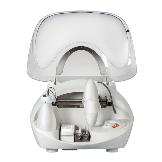
The instrument is controlled on-line in real time from an external dedicated PC. In each of the elements of the A15 analyser, BioSystems has used leading edge tech nology to obtain optimum ana- lytical performance, as well as taking into account eco no my, robustness, easy use and maintenance. A three-axis Cartesian operating arm prepares the reactions.
-
Page 9: Operating Arm
The A15 analyser has a tray with 4 free positions for racks of reag e nts or samples. Each reagents rack can carry up to 10 reagents in 20 ml or 50 ml bottles. Each samples rack can contain up to 24 tubes of samples. The samples can be patients, calibrators or controls.
-
Page 10: Reactions Rotor And Reading
Service manual 1.1.3. Reactions rotor and reading The preparations are dispensed in an optical quality methacrylate reactions rotor thermos tated at 37ºC. The optical absorbance readings are taken directly on this rotor. Each reaction can be read for 10 minutes. The readings are taken as they are programmed in each measurement procedure.
-
Page 11: Electronic System
1.2. FUNCTIONING OF THE ANALYSER The A15 analyser is an automatic random access analyser specially designed for performing biochemical and turbi- dimetric clinical analyses. The analyser performs patient-by-patient analyses and enables the continual introduction of samples. The analyser is controlled from a dedicated PC that is permanently com muni cated to the instrument.
-
Page 12: Transport And Reshipment Of The Analyzer
Service manual for the measurement procedures it is to carry out. The user may choose between performing the blanks and the calibra tors or not. If they are not performed, the analyser uses the last available memorised data. The controls can also be activated or not.
-
Page 14: Mechanical Elements
Service manual 2. MECHANICAL ELEMENTS 2.1. Instrument breakdown The physical structure of the analyzer can be broken down as follows: -Operating arm -X guide -Y guide -X carriage -Y carriage -Needle unit -Dispensing system -Thermostated probe -Dispensing pump -Tubes and containers -Container level control sensors -Racks tray with integrated washing station -Waste pump…
-
Page 15: Guide
2.2.1.1. X Guide. UPPER X TOOTHED AXIS LOWER X AXIS X START PHOTOSENSOR BEARING X AXIS X MOTOR X START PHOTOSENSOR TAB AXIS SUPPORTS This consists of two supports (7) that hold the steel axes (1 and 2) on which the X carriage moves. The photosensor (3) indicates the start position of the X carriage movement.
-
Page 16: Carriage
Service manual 2.2.1.2. X Carriage X CARRIAGE BODY UPPER X AXIS — RACK LOWER X AXIS X MOTOR Z MOTOR ENCODER XYZ INTERCONNECTION PCB BEARINGS The X carriage body (1) moves along the two axes (2, 3). The upper axis (2) acts as a rack. The X motor (4) is fitted with a pinion that moves the carriage.
-
Page 18: Needle Unit
Service manual 2.2.1.4. Needle unit Z GUIDE RACK Z MOTOR ENCODER TRANSMISSION AXIS RETURN SPRING THERMOSTATATION PIPE CONTROL PCB Y CARRIAGE The Z guide (1) supports the thermostatation pipe (7) and the control PCB (8) where the heating elements are located, together with the thermistor signal amplifier and level detection and the Z axis start photosensor.
-
Page 19: Dispensing System
2.2.2. Dispensing system The dispensing pump dispenses the preparations through the thermostated needle. The needle is washed internally and exter nally at the washing station. The racks tray makes it possible to position the samples to be analyzed and the required re a gents. The level of the distilled water and waste containers is controlled by the analyzer by capacity. 2.2.2.1.
-
Page 20
Service manual… -
Page 21: Tubes And Containers
(14) 3-CHANNEL ELECTROVALVE (15) ELECTROVALVE NUT The plastic body (1) joins the different elements that make up the pump. The transparent methacrylate fluidic chamber (2) makes it possible to observe the flow of liquid through the pump. The support (4) fastens the seal (3). The ceramic piston (5) dispenses by displacing a certain volume of liquid in the chamber.
-
Page 22: Container Level Control Sensors
Service manual 2.2.2.4. Container level control sensors. LEVEL DETECTION SHEETING SIGNAL CONNECTOR The analyzer has a capacitance system to control the level of the distilled water and waste containers. For this, there is an emission plane (1) under the bottles where a signal is injected through the connector (2). The base supporting the bottles is above this.
-
Page 23: Racks Tray With Integrated Washing Station
2.2.2.5. Racks tray with integrated washing station. TRAY WASHING STATION LEVEL DETECTION SHEETING WASTE PVC PIPE The plastic injection tray (1) is part of the base of the instrument. The washing station (2) is installed on the right. The plate (3) detects the level of the dispensing needle. The PVC tube (4) connects the washing station drain to the waste extraction pump.
-
Page 24: Reaction Rotor With Integrated Optical System
Service manual 2.2.3. Reaction rotor with integrated optical system. The reactions rotor is thermostated at 37ºC. The optical system, made up of a lighting system and a photometric system takes the readings directly on the rotor reaction wells. The lighting system has a halogen lamp, a filter drum for the selection of the wavelength form the appropriate beam of light.
-
Page 25
The dispensing system dispenses the reagents and the samples in the methacrylate rotor (1). The optical system measures the absorbance directly on the rotor wells. The aluminium heating canal (2) surrounds the rotor and keeps it at 37ºC. The canal is thermally insulated from the exterior by means of the moulded expanded polystyrene insula- tion (3). -
Page 26: Lighting System
Service manual 2.2.3.2. Lighting system BODY LAMP HOLDER HALOGEN LAMP LAMP HOLDER FASTENING FILTER WHEEL FILTER HOLDER FILTER HOLDER NUT MATCHED INTERFERENTIAL FILTERS WHEEL AXLE (10) HOME PHOTODETECTOR (11) FILTER MOTOR (12) DIAPHRAGM (13) FILTER WHEEL WINDOW COVER (14) FILTER WHEEL (15)
-
Page 27: Electronics Cover
The aluminium body (1) is the structure that supports all the elements of the lighting system. The lamp holder (2), fastened to the body by means of the fastening system (4), keeps the halogen lamp (3) in position without the need for adjustments.
-
Page 28: Main Cover Hinges
Service manual 2.2.5. Main cover hinges HYDRO-PNEUMATIC SPRING ARTICULATED STEEL STRUCTURE COVER OPEN PHOTOSENSOR (on right-hand hinge only) The two hinges enabling the raising of the main cover of the analyzer consist of an articulated steel structure (2) operated by a hydro-pneumatic spring (1). The right-hand hinge includes a photosensor (3) to detect whether or not the cover of the analyzer is open or closed.
-
Page 29: Base
2.2.6. Base LOWER PLASTIC CASING BASE WASHING STATION AND RACK TRAY ARM UNIT ELECTRONICS BOX DISPENSING PUMP REACTION ROTOR AND INTEGRATED OPTICAL SYSTEM BOTTLE LEVEL DETECTION PLATE LEVEL DETECTION PLATE (10) PUMP AND MICROPROCESSOR INTERCONNECTION BOARD (11) MAIN COVER HINGES (12) FRONT INDICATOR (13)
-
Page 30: Casings
Service manual 2.2.7. Casings FRONT CASING UPPER CASING MAIN COVER LOWER CASING ARM HOUSING ROTOR COVER RETURN SPRING COVER The front casing (1) is fastened to the upper casing (2) and the upper casing is fastened to the lower casing (4). The top cover (3) is transparent and lets users see the analyser in operation with the cover closed.
-
Page 31: Electronic System
3. ELECTRONIC SYSTEM Description of the electronics of the A15 analyzer. CPU Board (CIIM00026) Power supply board and source (SP150 & CIIM00015) Needle Board (CIIM00017) Photometry Board (CIIM00027) XYZ carriage interconnection board (CIIM00018) Rotor interconnection board (CIIM00029) Fluid interconnection board (CIIM00028)
-
Page 32
Service manual Connector Function Pins Not available Connection to communications board 1 — V DC (CIIM00036) 2 — GND 3 — Tx0 4 — GND 5 — Rx0 6 — GND 7 — GND 8 — Tx1 9 — GND 10 — Rx1 Connection to XYZ interconnection 1 — V DC… -
Page 33
Connector Function Pins Connection to rotor intercon- 1 — coil 2 motor filters nection board (motor and 2 — coil 2 motor filters Peltier signals) 3 — coil 1 motor filters 4 — coil 1 rotor motor 5 — coil 1 motor filters 6 — coil 1 rotor motor 7 — Peltier 8 — coil 2 rotor motor… -
Page 34
Service manual Analogical circuitry: The waste and system liquid sensors function through U6, U5 and U4, which generate and detect the signal responsible for detecting the waste and system liquid. These signals are sent and received through the fluid interconnection board (connected to the CPU board by J9). -
Page 36: Power Supply Board (Ciim00015)
Service manual 3.2 Power Supply Board (CIIM00015) This is made up of 2 different switched regulators and 1 voltage line that enable distribution of the power supply in accordance with the requirement of each subsystem. Connector Function Pins 24 V input 1 — 24V 3 — (GND) Output voltage of 6 V for lamp…
-
Page 38: Needle Board (Ciim00017)
Service manual 3.3 Needle Board (CIIM00017) This board conditions the thermistor signal associated with the thermostatation of the needle, the preamplification of the level detection signal and the Z home. It receives, from the needle unit, the thermostatation elements, the ther- mistor and the level signal detected by the needle itself.
-
Page 40: Photometry Board (Ciim00027)
Service manual 3.4 Photometry Board (CIIM00027) This board also has the heart of the absorbance measuring system for the samples to be analyzed. It is made up of a photosensor and an associated analogical-digital conversion circuitry (DDC112). Connector Function Pins Photometric board connection CIIM00029) 1 — 12 V 2 — GND…
-
Page 41: Xyz Interconnection Board (Ciim00018)
3.5 XYZ Interconnection Board (CIIM00018) This board interconnects the CP1 board with the X carriage. It distributes the X and Y motor signals and transmits the home signals of the X and Y movements. It also sends the encoder signal to the CPU board. Connector Function Pins…
-
Page 42: Communications Board (Ciim00036)
Service manual 3.6 Communications Board (CIIM00036) This enables communication with the exterior of the analyzer through a USB channel or a RS232 channel. It also includes an auxiliary RS232 channel for monitoring the functions of the analyzer during its execution. Connector Function Pins…
-
Page 43: Rotor Interconnection Board (Ciim00029)
3.7 Rotor interconnection board (CIIM00029) This interconnects the rotor with the CPU board. Connector Function Pins Rotor motor connection Power connection with board CIIM00026 1 — Coil 2 rotor motor 2 — Coil 2 rotor motor 3 — Coil 1 rotor motor 4 — Coil 1 motor filters 5 — Coil 1 rotor motor 6 — Coil 1 motor filters…
-
Page 44
Service manual Connector Function Pins Rotor cover sensor connection 1 — Cable 1 2 — Cable 2 Thermistor connection 1 — Cable 1 2 — Cable 2 1 — Front LED, red Front LED connection 2 — Front LED, black 3 — Front LED, green 1 — Photo sensor, yellow Connection Home motor filters… -
Page 45: Pump Interconnection Board (Ciim00028)
3.9 Pump interconnection board (CIIM00028) The pump interconnection board interconnects the CPU board with the dispensing pump, the waste pump, the electrovalve, the bottle level sensor and the instrument cover. List of LED diodes Connector Function Pins Waste sensor 1 — Waste sensor Connection signal with board CIIM00026 1 — Waste sensor 2 — System liquid sensor…
-
Page 46
Service manual… -
Page 47: Component Relation
3.10 Component relation Component Reference Home detector TCST1300 3 way electrovalve LVM115-6A-2U-1 from SMC Cover magnet Neodimio D4x5 Lamp 6V 10W Gilway L6402 Pump motor NMB23ML-C343V-1 Rotor motor NMB17PMKD18V Washing system motor SP600-EC-LC-L Filter wheel motor NMB23ML-C343V-1 X motor NMB23ML-C343V-1 Y motor NMB17PMKD18V Z motor…
-
Page 48
Filter 1=000 Integration Time= 20ms ( 40) Reference Time= 0ms ( 0) Firmware initialization Filter 2=340 Integration Time=205ms (400) Reference Time= Firmware Version: A15 User V3.12 0ms ( 0) Serial Number: 831050311 Filter 3=405 Integration Time= 51ms (100) Reference Time=… -
Page 49
155 126 112 108 106 110 121 146 S: Level Scales 161 128 113 110 106 112 121 151 A: Last A15 Stress Results 160 132 112 111 106 113 121 151 L: Actual Sensitivity of Level Detection 167 133 115 112 108 114 124 156… -
Page 50
Service manual L: Actual Sensibility of Level Detection 149 128 111 111 107 113 119 145 154 126 113 110 108 111 119 144 N: Activate additional information of level detection (only 155 128 115 111 110 113 124 145 internal use) 161 130 114 112 110 115 125 148 K: Deactivate the power supply… -
Page 51: Interconnection Between Boards
3.12 Interconnection between boards The following diagrams show the connections between the boards and the different elements that make up the analyzer.
-
Page 52
Service manual… -
Page 54
Service manual… -
Page 56
Service manual… -
Page 57: Schematic Liquid Circuit
3.13 Schematic liquid circuit…
-
Page 58: Service Program
4.1 Initialising the analyser To initialise the analyser in service mode, first launch the A15 Service application. The program first of all re- quests a user or technician ID to be used in the program. Depending on the type of user identified, access to the different parts of the program will be allowed or denied.
-
Page 59
Once the user has been identified correctly, the service program starts to initialise the analyser. This screen appears when the analyser has finished the previous operations done to enter the SERVICE mode. If the complete hardware of the analyzer is in correct conditions, the result “Hardware initiated correctly» displays. If any hardware element presents an operational problem, it will appear “Hardware not initiated completely”… -
Page 60: Adjustments
Service manual 4.2. ADJUSTMENTS These make it possible to make different parameter adjustments required for the correct functioning of the analyzer. All the values to be adjusted have certain limited ranges, indicated by the service program. These values are also given in an appendix at the back of this manual. If, after varying any of the parameters within its permitted range, the analyzer is not tuned up, it indicates that the corresponding system is broken and in need of repair.
-
Page 61: Adjustment Of The Rotor Thermostation System
is as close as possible to 37ºC. To make this adjustment, the analyzer must be initialised. The liquid to be dis- pensed is taken from the system liquid container or from the bottle of reagent selected by the technician. The technician must measure the temperature of the dispensed liquid with a thermometer calibrated at 37ºC.
-
Page 62: Adjustment Of The Positioning Of The Operating Arm
Service manual 4.2.3. Adjustment of the positioning of the operating arm This screen makes it possible to adjust the horizontal positioning (X, Y) of the arm. The arm housing must be removed to see the position of the needle. Before making the adjustments, visually check the verticality of the needle.
-
Page 63
There are two tools to carry out the adjustment process: one to adjust the reagent rack and the other for the pediatric rack. In order to carry out this XYZ rack adjustment, you may use the screen or keyboard buttons. Movements using keyboard: X axis movements: right and left cursor button Y axis movements: up and down cursor button… -
Page 64
Service manual 3. Activate the option Adjust with the tool 4. Select the number of rack to start the adjustment process. By default, it starts with number 1. 5. Place the rack in the selected position, place the tool in the well 1 of the rack with and press Start. 6. -
Page 65: Adjustment Of The Positioning Of The Rotor
Adjustment of Z-axis of tubes When the adjustment of the tray of pediatric racks is selected, it appears another adjustment: the Z relation between pediatric and tube. In order to carry out this adjustment, follow the following steps: 1. Place a diameter 15 rack in position 2 of the tray, with a tube in rack position 1. 2.
-
Page 66: Adjustment Of The Positioning Of The Filter Wheel
Service manual made through these wells at the wavelength selected by the technician. Once the readings have ended, the program shows a graph of the light intensity measured on the rotor steps. On this graph, the program indica- tes at which points the optical readings are made on each of the 3 wells when the analysis is made, with the coordinate of the reading point of the first well currently programd in the analyzer.
-
Page 67: Adjustment Of The Level Control Scales
4.2.6. Adjustment of the level control scales This screen makes it possible to set the level control scales with the empty waste and distilled water containers (0% capacity) and when they are full (100% capacity). The maximum capacity of the containers is approximately 3L.
-
Page 68: Adjustment Of The Level Detection Sensitivity
Service manual 4.2.7. Adjustment of the level detection sensitivity This screen allows fitting the sensitivity of the capa city level detection system of the probe. In order to make the adjustment, first of all you have to select the typs of racks: metal filled racks (grey color) or plastic racks (black color).
-
Page 69: Initialization Test
— Dispensing pump — Rotor — Filter wheel All the motor tests can be performed without the covers and housing of the analyzer. After the verifications, the operating arm always returns to its resting position. To test the motor of the dispensing pump, the arm is positioned over the washing station.
-
Page 70: Loss Step Test
Service manual 4.3.1.3. Loss step test This test makes it possible to check if a motor misses steps when performing a certain sequence of movements. The test can be carried out with the speed and acceleration used in the normal functioning of the analyzer or with these magnitudes increased by 10% to check the functioning safety margin.
-
Page 71: Maximum Z Verification Test
4.3.1.6 Maximum Z verification test This test checks that the needle does not collide with the bottles on the rack tray. Select the rack type (reagent, paediatric, 30 mm or 15 mm), the position of the rack on the tray and the position of the bottle or well on the rack. Press the Start button to move to the selected position and check if the needle collides with the bottle or well or if there is space between the needle and the bottle.
-
Page 72: Functioning Test
Service manual To carry out these tests, the dispensing system should be primed. The following is a description of the different tests that can be performed. 4.3.2.1. Functioning test This test makes it possible to manually switch the selected device. 4.3.2.2.
-
Page 73: Needle Thermostatation System Test
4.3.5. Needle thermostatation system test This screen makes it possible to check that the dispensing temperature of the reactions is around 37ºC. To make this adjustment, the analyzer must be initialised. The technician must measure the temperature of the dispen- sed liquid with a thermometer calibrated at 37ºC.
-
Page 74: Needle Rotor Thermostatation System Test
Service manual 4.3.6. Needle rotor thermostatation system test This screen makes it possible to check that the temperature of the rotor reactions is 37ºC. To make this test, the analyzer must be initialised. The methacrylate rotor can be automatically filled with distilled water by pressing the corresponding button.
-
Page 75
wells of the count numbers obtained with each filter. The screen shows the corresponding alarms in the case of anomaly. It is also possible to access a screen where it is possible to manually vary the integration times to check their effect on the count numbers. And another screen where it is possible to assign calculated in- tegration times as reference integration times for each filter. -
Page 76: Darkness Counts
Service manual 4.3.7.2. Darkness counts The program shows the current integration times for each filter. On running the test, the analyzer positions the covered filter and measures the darkness counts with each of the integration times. Each time an optical reading is taken, the analyzer subtracts these darkness counts from the count numbers measured to obtain the light intensity.
-
Page 77: Stability
4.3.7.4. Stability This test takes absorbance readings during 30 minute with the filter wheel in fixed position. The technician can choose the rotor well on which he wishes to take the readings and fill it with the liquid he desires. He can choose which wavelength he wishes to use.
-
Page 78: Absorbance Measurement
Service manual 4.3.7.6. Absorbance measurement This test enables individual absorbance readings. The technician can choose the rotor well on which he wishes to take the readings and fill it with the liquid he desires. He can choose which wavelength he wishes to use. The screen shows the count number obtained, the absorbance with regard to the corresponding base line, the value of the base line.
-
Page 79: Level Control Scales Test
4.3.8. Level control scales test This screen makes it possible to check the functioning of the level control scales of the waste and distilled water containers. The technician must select which scales he wishes to check and place a certain amount of liquid in the corresponding container.
-
Page 80: Pc-Analyzer Communications Channel Test
Service manual 4.3.10. PC-Analyzer communications channel test On pressing the Test button, the computer attempts to establish communication with the analyzer. The program tells the technician if it has been possible or not. The technician can select Automatic Configuration or Manual Configuration. In the case of the latter, he can define the Port and the Speed.
-
Page 81: Photometry Tool
can be cancelled at any time. Once the test has been launched, the screen provides regular information about the current status of the pro- cess. If an error occurs during the process, the test ends and the screen displays a message indicating the element causing the error.
-
Page 82: Utilities
Service manual 4.4. UTILITIES The program contains various technical utilities. These utilities are also accessible from the user program. 4.4.1. Disassembly of the dispensing needle On clicking on the Disassemble Needle button, the operating arm positions itself over the rack tray. The program alerts the technician to remove any object positioned under the arm.
-
Page 83: Fluid System Supply
top fitting. If, while handling the needle, the carriage rises due to the pressure made by the technician, press the Lower Needle button for the needle to descend once again. Once the needle has been reassembled on the analyzer, press the Park button for the needle to rise. It performs the self-centering test and the arm finally returns to its parked position.
-
Page 84: Cleaning Of The Dispensing System
Service manual 4.4.3. Cleaning of the dispensing system On pressing the Wash button, the analyzer washes the dispensing system internally and externally. To perform this operation, the operating arm is moved to the washing station. The technician can choose between perfor- ming the wash with distilled water or wash solution.
-
Page 85: Configuration Of The Filter Wheel
the luminosity of the photometric system. The lamp must be changed with the analyzer in sleeping mode. If the analyzer is on standby mode, the program shuts it down automatically. The lamp must never be touched with fingers. Once the new lamp has been installed and the covers of the optic and rotor put back, access the change lamp utility and press the Test button.
-
Page 86: Read/Load Adjustments And Cycles
Service manual 4.4.7 Read/load adjustments and cycles From this screen, it is possible to read the current adjustments that the analyser is using by pressing the button Read Adjustments. It is allowed to save these adjustments in a file. The technician selects the name and location of this file. Also from this same screen and with the button Load Adjustments, the technician is allowed to select an ad- justment file and to load it in the analyzer.
-
Page 87: Change The Rotor Type
The programme automatically saves a copy of the adjustments and cycles read in a file. This file is located in the following folder: c:Program filesA15 ServiceAdjustments When a physical element of the analyser has to be changed, e.g. the Z axis belt, the counter must be reset to zero for it to correspond to the number of cycles actually stored in the analyser.
-
Page 88: Register
Service manual 4.5. REGISTER This enables the management of past adjustments, tests, incidences, repairs and maintenance of the instrument. 4.5.1. Introducing the analyzer serial number The technician can enter the analyzer serial number so that it appears on printed service reports. If an ente- red serial number is changed, the service records are reinitiated.
-
Page 89: Service Reports
4.5.2. Service Reports The program can display and print various service reports. The printed reports contain the analyzer serial number and the name of the current technician. Reports are stored organised by: Adjustments, Tests, Utilities, Monitor and Summary of actions and tasks carried out.
-
Page 90: Users
Service manual 4.5.4. Users Two types of user can be created with different access levels: · SAT. This user has full access to the programme. This user has permission to create and/or delete other users. · User. This user has restricted access to the programme. This user can only perform the tests and run the utilities.
-
Page 91: User’s Program
To activate the option of level of access to the analyser, the first time you should enter as administrator, whose values are: Name of user: admin access key: A15 with this screen, the application with the operation by passwords is configured. The first time that the program is activated, it forces the user to change the initial password.
-
Page 92: Reagent Consumption
Service manual • Operator, is the user with a lower level of access to the application. He can only do working sessions, reports of current and historical results, and validate quality control results. In the screens of programming of techniques and contaminations, he can look up programming values, but he can not modify any parameter.
-
Page 93
FilesA15Reagents and the contents of the file shows similar this: REAGENT CONTROL CONSUME REPORT Initial Date: 02/11/2004 Final Date: 02/12/2004 Test Blank Prep. Calibrator Pre Control Prep. Patient Prep. Total Prep. Vol. R1 (uL) Vol. R2 (uL) glucose 1332… -
Page 94: Maintenance And Cleaning
Service manual 5. MAINTENANCE AND CLEANING First of all, this chapter gives a step-by-step description of the different operations required for both the preventive maintenance and repair of the analyzer. The following are basic recommendations for the preventive maintenance of the instrument.
-
Page 95: Removing The Main Cover
5.1.1.3. Removing the main cover a) Open the analyzer cover. b) Remove the two bottom screws that hold the cover to each hinge. c) Pull the cover upwards.
-
Page 96: Removing The Upper Casing
Service manual 5.1.1.4. Removing the upper casing a) Remove the front housing. b) Remove the main cover. c) Remove the screws as shown in the following figures. d) Remove the casing by pulling it upwards.
-
Page 98: Removing The Spring Protector
Service manual 5.1.1.5. Removing the spring protector a) Remove the three screws at the rear b) Pull the protector upwards. 5.1.2. Operating arm 5.1.2.1. Fully removing the operating arm a) Remove all the analyzer housing.
-
Page 99: Changing The Arm Hose
b) Disconnect the connector (1) that goes to the board that goes to the needle unit and cut all the flanges required. c) Disconnect the Teflon dispensing pipe (2). d) Remove the cover that covers the X carriage interconnection board (3). Cut the flanges that hold the flat bands and disconnect them from the board.
-
Page 100: Changing The X Motor
Service manual 5.1.2.3. Changing the X motor a) Remove all the analyzer housing. b) Unscrew the studs (1). c) Remove the rack (2) and let the arm rest on its front part. d) Remove the cover and the interconnection board (3). e) Remove the screws (4) and remove the motor.
-
Page 102: Changing The Y Motor
Service manual 5.1.2.4. Changing the Y motor a) Remove all the casings from the analyser except for that of the needle unit. b) Connect the motor cable (1). c) Remove the motor by removing the screws (2). d) Change the motor (with pulley). e) Remove the fastening plate (3).
-
Page 103: Changing The Y Motor Belt
d) Remove the motor axle by unscrewing the stud. e) Fit the axle to the new motor. f) Refit the motor but without tightening the studs (1). g) Fit the X motor and the interconnection board (3). h) Adjust the axis (4) so that the encoder is centred on the photosensor (5) and tighten the studs (1). 5.1.2.6.
-
Page 104: Dispensing System
Service manual 5.1.3. Dispensing system 5.1.3.1. Changing the thermostated pipe. a) Remove the arm casing. b) It is recommendable to remove the needle before handling the unit to prevent it from being damaged. c) Disconnect the electrical connector (1) and the Teflon pipe (2) and remove the flanges (3). d) Remove the protective cover (4).
-
Page 105: Changing The Dispensing Pump Seal
5.1.3.2. Changing the dispensing pump seal a) Remove the fluidic chamber (1). b) Remove the washer (2). c) Replace the seal (3). d) Refit the washer (2). d) Refit the fluidic chamber on the pump by tightening the four screws gradually.
-
Page 106: Changing The Dispensing Pump Motor
Service manual 5.1.3.3. Changing the dispensing pump motor a) Remove the dispensing pump by first of all unscrewing the nuts (1) and then the bolts (2) from the base. b) Remove the motor by removing the screws (3). c) Unscrew the body (4). d) Loosen the Allen bolt and remove the endless screw and the axial bearing (5).
-
Page 107: Changing The Dispensing Electrovalve
5.1.3.4. Changing the dispensing electrovalve a) Disconnect the connectors (1) and the electrical connector. b) Remove the screws (2) that hold the electrovalve in position. c) Fit the new electrovalve. Do not tighten the screws to excess so as not to deform the plastic body of the electrovalve and damage its leakproof quality.
-
Page 108: Reactions Rotor And Reading
Service manual 5.1.4. Reactions rotor and reading 5.1.4.1. Changing the rotor temperature probe a) Remove the upper casing. b) Disconnect the electrical hose from the interconnection board. c) Remove the thermal insulation from the temperature probe. d) Unscrew the probe (2). e) Clean the thermal silicone form the housing and put fresh thermal silicone on the end of the new probe.
-
Page 109: Fully Removing The Rotor
5.1.4.2. Fully removing the rotor a) Remove the upper casing. b) Disconnect the electrical hoses and the lampholder (1). c) remove the rotor from the base by removing the 3 leg screws. 5.1.4.3. Changing the rotor Peltier cells a) Remove the complete rotor. b) Remove the bolt (1) and the insulation (2) and the temperature probe (3).
-
Page 110: Changing The Rotor Cover Detector
Service manual 5.1.4.4. Changing the rotor cover detector a) Remove the rotor completely and remove the insulation. b) Unscrew the stud (1) and remove the sensor (2). c) Unsolder the sensor and then solder again. d) Refit the sensor. 5.1.4.5. Changing the rotor start photosensor a) Remove the rotor completely and remove the insulation.
-
Page 111: Changing The Rotor Motor
5.1.4.6. Changing the rotor motor a) Remove the rotor completely. Remove the insulation. b) Remove the rotor covers. c) Remove the nuts (1). d) Remove the motor from below. Disconnect the hose. e) Fit the new motor on the unit. f) Perform the miss test on the rotor motor and the rotor positioning test in the service program to check that the gap between gears is correct and that the system functions correctly.
-
Page 112: Changing The Lamp
Service manual 5.1.4.8. Changing the lamp The analyzer is fitted with a 6 V 10 W halogen lamp with an estimated average lifetime of 2,000 hours. It is recom- mended that you change the lamp every year even though its lifetime has not run out. When the lamp needs to be changed, access the Change lamp utility of the user programme and follow the steps indicated by the programme itself.
-
Page 113: Changing An Optical Filter
it 180º around its longitudinal axis. The programme itself requires the user to place the lamp in the two possible positions and check in which of the two maximum light intensity is obtained in the optical system. 5.1.4.9. Changing an optical filter a) Access the Filter Wheel Configuration screen of the user or service programme.
-
Page 114: Changing The Filter Wheel Motor
Service manual 5.1.4.12. Changing the filter wheel motor To change the filter wheel motor, proceed as indicated in the section titled Changing the filter wheel. 5.1.5. Electronic Systems 5.1.5.1. Changing the X, Y and encoder start photosensor a) Remove the upper casing. b) Disconnect all the connectors (1).
-
Page 115: Changing The Microprocessor Board
5.1.5.2. Changing the microprocessor board a) Fold down the back cover of the electronics. b) Disconnect all the hoses from the board. c) Remove the bolts (1). d) When installing the new board, reconnect all the connectors carefully. 5.1.5.3. Changing the power supply board a) Fold down the back cover of the electronics.
-
Page 116: Changing The Main Power Supply Source
Service manual 5.1.5.4. Changing the main power supply source a) Fold down the back cover of the electronics. b) Remove the input and output connectors by unscrewing the bolts (1). c) Remove the 3 bolts (2) that hold the source in position. d) Remove the source.
-
Page 117: Changing The Front Indicator
a) Remove the screws from the photometric system support cover. b) Slightly move the support cover towards the centre of the rotor and remove it from its housing. c) Disconnect the flat band from the photometric system board. d) Change the board. e) Refit the support cover in place ensuring that the flat band is not folded.
-
Page 118: Changing The Firmware Program
Service manual b) Disconnect the hose from the rotor interconnection board. c) Pull the fastening ring (1) down. d) Pull the LED (2) up to remove it. 5.1.5.7. Changing the firmware program The firmware of the analyzer resides in a permanent flash memory. The change of this program can be made through the computer without the need for changing the memory chip.
-
Page 119: Care And Cleaning
It is recommended that the following maintenance actions are performed annually or every 2,000 working hours. Operating arm Check the state and tension of the belt. Replace the elements in an unsatisfactory state. Make the adjustments and tests related to the service program. Dispensing system.
-
Page 120: Cleaning The Dispensing System
Service manual To remove them and refit them, the corresponding instructions given in the Maintenance chapter must be carefully followed. Avoid touching the useful area of these elements with fingers. The filters and the photodiode must be held by the sides. Do not touch the lamp bulb. To handle the lamp, use the wrapping, cutting it at the terminal end and squeezing it until they come out.
-
Page 121: A I. Technical Specifications
A I. TECHNICAL SPECIFICATIONS PLEASE NOTE The manufacturer accepts no liability for damage caused by incorrect use of the apparatus. GENERAL SPECIFICATIONS Automatic random and continual access analyzer aimed at giving results per patient, with direct photometric reading over a reactions rotor. Preparation cycle time 24 s (up to 150 prep/h) Warm-up time…
-
Page 122
Service manual DISPENSING PUMP Ceramic piston with PTFE-graphite seal Piston diameter 8 mm Displacement 25 mm Dispensing volume 3 µL — 1250 µL Resolution 0.126 µL Fuzziness <1% up to 3 µL Dispensing speed max. 880 µL/s Programmable reagent volume 10 µL -440 µL Programmable sample volume 3 µL — 40 µL… -
Page 123
VGA Monitor, minimum resolution of 640×480 Mouse RS-232 serial channel or USB connector The insulation level of the communications channel of the A15 analyzer is reinforced (the insulation of the communi- cations channel of the computer must also be reinforced) POWER REQUIREMENTS… -
Page 124
Service manual MAXIMUM SIZE OF ANALYZER With the lid closed: Width: 840 mm. Depth: 670 mm. Height: 615 mm. With the lid open: Width: 840 mm. Depth: 670 mm. Height: 1,025 mm. The manufacturer reserves the right to modify any technical specification without prior notice. -
Page 125: A Ii. Adjustment Margins Tables
A II. ADJUSTMENT Level detection sensitivity Paediatric rack [45,90] MARGINS TABLES 13/15mm tube sample rack [45,90] Reagent rack [25,45] Main voltage measurement points Positioning of the dispensing point CIIM0015 Power supply board Dispensing rotor [90,120] TP1 — 6V [5.6-5.8] V Fine rotor X [35,200] TP2 — 12V…
-
Page 126: A Iii. List Of Consumables, Accessories And Spares
If any of the components of the analyzer deteriorate of if any of the perishable materials are required, always use original BioSystems material. The following table shows lists of components that may be required. To purchase said components, please contact your usual distributor and order each element using its corresponding code. This will simplify work and minimise errors.
-
Page 127
List of spares exclusive to the technical support service. CODE DESCRIPTION (Ordered by code) CODE DESCRIPTION (Ordered by description) CA13308 CD-ROM with Service programme MO13358 A15 fan and Service manual AC13365 Arm hose VA10355 Mains connector CA13393 Base cover ZO10407… -
Page 128: A Iv. List Of Required Tools
Service manual A IV. LIST OF REQUIRED TOOLS Set of metric Allen keys. Loctite 243 screwfastener or similar Mechanical grease ELESA NT1 (for ceramic pump only) (AC13079). Heat silicone or similar Soldering iron Screwdrivers or two 3 mm Allen keys. Loctite 245 or similar (for ceramic pump only).
-
Page 129
Change in the versions of user program Date version Changes 04 /04/06 3.2.1 First release version 20/07/06 3.2.2 New button in the tools menu, reset the historical base line Fix the options of the initial and final wash. Delete the menu to choose the parameter of initial and final wash. -
Page 130
Service manual Compatibilities table User A25 3.2.1 3.2.2 3.3.0 3.3.1 3.3.2 4.0.0 4.1 firmware 2.90 2.92 3.10 3.12 3.14 3.20 3.24 3.28 3.50 3.61 It is advisable to always install the last existing version of firmware. -
Page 131
BIOSYSTEMS, S.A. Costa Brava, 30, 08030 Barcelona — Spain Tel: 34-93 311 00 00 Fax: 34-93 346 77 99 e-mail: biosystems @biosystems.es http://www.biosystems-sa.com…
|
Detail Specifications: 1469/1469602-a15.pdf file (10 Nov 2022) |
Accompanying Data:
biosystems A15 Laboratory Equipment PDF Service Manual (Updated: Thursday 10th of November 2022 11:50:27 PM)
Rating: 4.1 (rated by 42 users)
Compatible devices: AEROSPRAY 7122, Multitron, ETS-LINDGREN SuiteSentry, INT883, Mega Star 600, Atomic LS EFI 2950, VisGuard 2 Extractive, UVCC200 80W.
Recommended Documentation:
Text Version of Service Manual
(Ocr-Read Summary of Contents, UPD: 10 November 2022)
-
48, Service manual 48 The labeled connector COM2 is the auxiliar connector. This connector is used to communicate with a second serial port in the computer. The function of this cable is to mo- nitor the internal states of the analyser. To show all this information, the user should execute the program: windows HyperTerminal and congure with the following parameters: Prog…
-
91, biosystems A15 91 4.7 User’s program In this section, the service options in the user program will be described. These options are intended to con- gure the user’s access level. Each section explains how to manage and create different levels of access to the user program of the analyser. When the program is installed for the rst time, there is not a created user and access to t…
-
93, 93 c:Program FilesA15Reagents and the contents of the le shows similar this: REAGENT CONTROL CONSUME REPORT Initial Date: 02/11/2004 Final Date: 02/12/2004 Test Blank Prep. Calibrator Pre Control Prep. Patient Prep. Total Prep. Vol. R1 (uL) Vol. R2 (uL) glucose 1 0 0 5 6 1332 0 alt 1 0 0 3 4 888 0 bilir…
-
104, biosystems A15 Service manual 104 5.1.3. Dispensing system 5.1.3.1. Changing the thermostated pipe. a) Remove the arm casing. b) It is recommendable to remove the needle before handling the unit to prevent it from being damaged. c) Disconnect the electrical connector (1) and the Teon pipe (2) and remove the anges (3). d) Remove the protective cover (4). e) Remove the …
-
99, biosystems A15 99 b) Disconnect the connector (1) that goes to the board that goes to the needle unit and cut all the anges required. c) Disconnect the Teon dispensing pipe (2). d) Remove the cover that covers the X carriage interconnection board (3). Cut the anges that hold the at bands and disconnect them from the board. e) Unscrew the four studs that fasten t…
-
103, biosystems A15 103 d) Remove the motor axle by unscrewing the stud. e) Fit the axle to the new motor. f) Ret the motor but without tightening the studs (1). g) Fit the X motor and the interconnection board (3). h) Adjust the axis (4) so that the encoder is centred on the photosensor (5) and tighten the studs (1). 5.1.2.6. Changing the Y motor belt a) Loosen the Y motor (see section).…
-
23, 23 2.2.2.5. Racks tray with integrated washing station. (1) TRAY (2) WASHING STATION (3) LEVEL DETECTION SHEETING (4) WASTE PVC PIPE The plastic injection tray (1) is part of the base of the instrument. The washing station (2) is installed on the right. The plate (3) detects the level of the dispensing needle. The PVC tube (4) connects the washing station dra…
-
89, 89 4.5.2. Service Reports The program can display and print various service reports. The printed reports contain the analyzer serial number and the name of the current technician. Reports are stored organised by: Adjustments, Tests, Utilities, Monitor and Summary of actions and tasks carried out. In all cases, it is possible to select the actions carried …
-
109, 109 1 2 5.1.4.2. Fully removing the rotor a) Remove the upper casing. b) Disconnect the electrical hoses and the lampholder (1). c) remove the rotor from the base by removing the 3 leg screws. 5.1.4.3. Changing the rotor Peltier cells a) Remove the complete rotor. b) Remove the bolt (1) and the insulation (2) and the temperature probe (3). b) Remove the fan (4) and the corre…
Recommended Instructions:
PEXSATA22, The Home Center, CRA 210, AX411 Access Point


-
NucleoCounter® NC-202™ Instrument User Guide P/N 991-2020 Revision 1.1 November 2019 ChemoMetec A/S Gydevang 43 · DK-3450 Allerød · Denmark Telephone: (+45) 48 13 10 20 Website: www.chemometec.com E-mail: [email protected] …
NucleoCounter NC-202 28
-
Filling of the rackSwitch the motor on and homogenize the sample by gliding the „ball-bea-ring head“ over the bags, using the handle.Remove spills of extraction buffer immediately fi rst with a soft cloth wetted with water, then wipe dry — in particular when buffer entered the ball-bearing head. Occasionally grease the two gliding axes (5) and the nipple (6) at th …
HOMEX 6 2
-
TURBOTURBO -TWIST-TWISTTMTMUV SterilizerUV Sterilizer12 Month Limited WarrantyWHAT THE WARRANTY COVERS:Central Aquatics (Company) warrants this product (see Exclusions below) to the original purchaser against defective material and workmanship that occurs during normal use for 12 months from the date of original purchase. Company will, at Company’s option, either repair or replace produ …
TurboTwist Series 6
-
Operation and Instruction Manual REV C Koehler Instrument Company, Inc. 1595 Sycamore Avenue • Bohemia, New York 11716-1796 • USA Toll Free: 1-800-878-9070 (US only) • Tel: +1 631 589 3800 • Fax: +1 631 589 3815 http://www.koehlerinstrument.com • e-mail: [email protected] Petroleum Testing & Analysis Instrumentation • Custom Design & Manufacturing …
K430X2 24
Additional Information:
Popular Right Now:
Operating Impressions, Questions and Answers:
-
Описание -
Характеристики -
Производитель -
Доставка, оплата -
Ввод в эксплуатацию
Описание BioSystems A-15
Система для клинической химии и турбидиметрии A-15 является той основой, на базе которой ваша лаборатория будет двигаться к прогрессу и большей эффективности. В том же направлении, в каком эволюционировала жизнь, А-15, благодаря своим возможностям и простоте в использовании, адаптирует Вашу рутинную работу в прогрессивном направлении.
Преимущества BioSystems A-15
- А-15 означает изменение в работе лаборатории, эволюция к простой и эффективной автоматизации;
- А-15 может и должен работать в каждой лаборатории. Интеллектуальная система Анализатора Random Access надежная и производительная;
- А-15 делает возможным расширение лаборатории, увеличению панели тестов по клинической химии и турбидиметрии и пропускной способности. А-15 минимизирует объем потребляемых реагентов на тест, потребление воды, ежедневное обслуживание, расходные материалы. Все это оптимизирует оперативные расходы лаборатории система для клинической химии, оптимизирующая ресурсы лаборатории.
Характеристики BioSystems A-15
- Сенсорный дисплей: Нет
- Принтер: Внешний
- Подключение к ЛИС: Да
- Производительность, тестов/час: 150
- Тип анализатора: Автоматический
- Тип реагентов к анализатору: Открытая система
- Максимальное количество проб на борту: 24
- Максимальное количество реагентов на борту: 10
- Наличие модуля электролитов ISE: Нет
- Встроенный считыватель штрих-кодов: Да
- Использование в ветеринарии: Нет
Испанская компания BioSystems S.A. была основана в 1981 году в городе Барселона и по прошествии уже более чем 30-ти лет присутствия на рынке лабораторной диагностики обрела широкую известность как разработчик и производитель высококачественных реагентов и оборудования для проведения биохимических, турбидиметрических, аутоиммунных и прочих лабораторных исследований в области in-vitro диагностики.
|
Хранилище файлов |
Правила добавления:
Внимание !!!
Перед тем как загрузить файл, убедитесь, что его нет в «Хранилище файлов» для этого воспользуйтесь поиском.
При добавлении файлов в поле «Название материала» указываем марку аппарата, так как на шильдике или по паспорту.
В поле «Краткое описание» пишем что-это: схема; сервис мануал; руководство по эксплуатации и т.д. Также напишите формат материала, какой программой он сделан.
За сохранность и работоспособность файлов(ссылок) загруженных на сторонние файловые хостинги, Администрация сайта ответственности не несет.
Для загрузки файлов в «Хранилище» воспользуйтесь архиватором WinRAR или 7-Zip, максимальный объем загружаемого файла должен быть не более 15Mb.
Администрация сайта оставляет за собой право удалять и редактировать файлы.
Для скачивания с 4Shared.com необходимо зарегистрироваться и создать аккаунт на 4shared.com или пользоваться другим способом скачивания которые там же предлагаются.
BioSystems A-15 (service manual)
Гостям запрещено просматривать данную страницу, пожалуйста войдите на сайт как пользователь.
[
Регистрация
|
Вход
]
Вопросы по ремонту медицинской техники | Теоретические основы медицинского приборостроения | Информационный раздел | Информация о сайте | Хранилище файлов | Сертификаты и регистрационные удостоверения | Навигатор по сайту |
Написать администратору