Overview
Before moving into each topic we would like to give our new users a taste of with Bizagi Modeler.
To do so, we will take you through a step by step guide to diagram a common process: the Purchase Request.
Before you start
It is necessary to have Bizagi Modeler installed before starting this guide.
What you need to do
This is a guide on how to use the tool to model and document your processes. We encourage you to review in detail each step and to click the links in each section for more information.
Understand your process: Purchase Request
When modeling a process it is important to understand the steps it goes through, the routing, the inputs and outputs.
The Purchase Request process formalizes the acquisition of goods and services. Although the process can change substantially from one company to another, it is a good place to start modeling the company processes.

|
|
|
The Purchase request process begins with the identification of products or services needed by the applicant. According to the price of the request, it needs approval from their boss. The boss may approve the request, request changes, or reject it.
If the request is approved, the process evaluates if the boss has the level of authority to approve the amount. If the boss does not, the request is escalated to his/her boss, and so on.
Once the request has been approved, quotations are requested by the Purchasing department, to have the appropriate number of potential suppliers. Quotations are selected according to the delivery date, price, and quality.
The Purchasing department selects a supplier and generates a Purchase Order that is sent to the selected supplier and saved in the company´s ERP.
Process Modeling
To model the Purchase Request process, open Bizagi Modeler desktop application. The first thing you see in a new model is a diagram with an empty pool:

As a good practice, the pool has the same name as the process, to change the name of any element double-click it, press F2, or right-click it and select from the display menu.

Now before adding shapes to the diagram, identify the main roles (or resources) related to the process.
In this case, there are 3 participants: the applicant, the boss, and the purchasing department. Each participant is represented by a lane. Therefore, you should add 3 lanes in the pool with their respective names.
To add any element to the diagram you can drag a drop them from the Palette on the left. Drag and drop the lanes in the pool and name them as explained before.


Then, add the shapes to the diagram.
All processes must have a Start event from which the process begins. Drag and drop the Start event into the lane of the participant that starts the process, in this case, the Applicant:

The next step is the first task: . To create the task you have two options:
•Drag and drop the task shape and connect the start event to it.


•Use the Pie Menu displayed from the start event, with this option the task is automatically connected to the start event:


Repeat this to create the task.

At this point, the phase of the process is finished and it is necessary to include its milestone. To do so drag and drop the milestone shape and rename it.

To start diagramming the phase create its milestone just like the phase.

Continue adding the required shapes until your diagram is complete.
To connect two elements in a sequence flow, using the Pie Menu, drag the corresponding shape to the second element. They will be automatically connected.

The following image displays the basic diagram of the process.

Transform elements
Once you have diagrammed the basics of the process, some adjustments are needed to reflect the reality of the process.
•The Notification Tasks consist of emails automatically sent based on a decision by the Immediate Supervisor (Boss). Therefore these tasks must be changed to Script tasks.
•The Task must be transformed to a Sub-process where several activities take place to select a supplier.
•The Task is also a Sub-process where the purchase order is sent to the Supplier and created in the ERP system.
To do these adjustments it is not necessary to introduce another element to the process, but to change the existing elements. For example to change the task, right-click it. In the display menu go to and select . Repeat this for the other two Notification tasks.

For the and tasks follow the same procedure, right-click the tasks and select .

Sub-process
Now is necessary to define the tasks that take place within each sub-process. To do so right-click the sub-process and select .

Bizagi asks if you want to create a new process for the sub-process or if you want to assign one to it. As we haven’t created any other process, a new process is needed, hence choose this option.

With this, a new diagram is created for you to model the sub-process. Repeat this for the sub-process.

In these two new diagrams, model the two sub-processes the same way we did with the process. Then rename the diagrams the same way an element is renamed.


In the sub-process, the services task might fail, because of this it is necessary to create an attached event to manage this error.
To do so right-click the task, go to and select . Then connect it to the following task.

Once you have modeled these two sub-processes you have finished modeling your first process.
The next step is to document it.
Process Documentation
Documenting a process is one of the most important steps when creating a model in Bizagi Modeler. This is where all relevant information for the process is included in the model so any user can understand it. You can include information at process level as well as detailed information at an element level in your diagram.
To add information at the process level right-click outside of the boundaries of the pool and select .
This enables the window at the right of the screen, where you can include: name, description, version, and author of the process.
You can also open this window by pressing the key.

With the displayed, select any element, and their respective properties will be shown.
Thereby, you can enter detailed information about each step of your flow (each element).
Task Documentation
In tasks documentation, you can also include Resources that are related to each role of the RACI Model.

A resource is a Business Entity or Role that controls or is responsible for a task. To define the resources of the model click the option in the tab.
, or any resource. In the model create the resources of the 3 main participants of the process: Applicant, Boss and Purchasing department.

Select and enter the name, description, and type (role or entity) of the resource.

Once the resource is created you can associate it to any task role.

Now document all the tasks of the model.
Create as many resources as necessary, however, it is not necessary to have resources in all roles of a task. For example, in a script task, as it is an automatic task, there may be no roles or just a performer.
Gateway Documentation
In the gateway’s properties, when alternative paths are available, documentation is included as conditional expressions for each decision branch representing a path.
You may define the condition for each path either in the Gateway itself, or in each of its decision branches.
To define the conditions of the gateway, on its properties window, go to the tab. In the , for each of the outbound paths there is a corresponding row identified by the branch name. In the model the gateway has 4 outbound paths: No, Changes are required, Requires another approval and Yes.

You may either define a conditional expression for the selected path or designate it as the Default path (the path that is chosen if no other conditions are met in other out coming flows). Note the visual representation of a default path is a small oblique line crossing the decision branch.

Once you have documented the basic properties of all the elements of the model. You can extend your documentation to include any type of information that you find relevant for your processes, through extended attributes.
Next steps
The Enterprise plan journey for the Bizagi Modeler services is to: create a model, which has been explained in this guide, save the model to the cloud, collaborate with your pairs or others to improve your model and finally publish the process to the end users.

There are also additional features that are useful for you:
•Compare your model with our It can be downloaded from the Bizagi Xchange web page.
•Publish your complete documentation. You can choose between multiple formats.
•Exchange your model. You can exchange your model in multiple formats.
•Simulate the process flow with Bizagi Modeler simulation tool (Only for Bizagi Modeler paid plans).
Remember that Bizagi Modeler offers advance features exclusive for certain paid plans. In the following article, you can overview the most relevant features available in each plan and choose the appropriate one for you.

- Bizagi Modeler — это бесплатное приложение для моделирования процессов в BPMN с возможностью совместной работы. Отлично подходит, когда ваше предприятие и сотрудники уже полюбили BPMN, но еще не готовы инвестировать деньги в средства моделирования.
В этой статье расскажу как это начать использовать приложение, какие имеются плюсы использования Bizagi Modeler для совместной работы.
1. Установка
Качаем Bizagi modeler по ссылке и устанавливаем.
При первом запуске ПО попросит регистрацию, она обязательная. Из-за блокировок РКН страничка регистрации не всегда открывается, и бывает что зарегистрироваться не получается. Чтобы избежать регистрации найдите файл BizagiModeler.exe.config. По-умолчанию он лежит в директории C:Program Files (x86)BizagiBizagi ModelerModeler

Откройте файл блокнотом и впишите строчку
Для тех, кто торопится
Я разработал бесплатный облачный сервис для рисования и обсуждения диаграмм с коллегами. Он очень экономит время и делает обсуждение удобным. Bizagi больше не нужен! Регистрируйтесь!
Для тех, кто торопится
Я разработал бесплатный облачный сервис для рисования и обсуждения диаграмм с коллегами. Он очень экономит время и делает обсуждение удобным. Bizagi больше не нужен! Регистрируйтесь!
<add key=»IsRegistrationDisabled» value=»true»/>

Теперь приложение не будет требовать регистрации.
2. Общая папка и первая модель
Создайте общую папку на сервере или в яндекс-диске. В этой папке мы будем хранить файлы модели. Выдайте права коллегам на чтения или запись по инструкции. Убедитесь, что все коллеги имеют доступ до папки.
Откройте Bizagi Modeler, моделируйте процесс и сохраняйте файл как общий в созданную папку:

3. Работа с конкретным файлом
Теперь, когда вы открываете такой файл в Bizagi Modeler, вы видите такую штуку:

Модели в Bizagi Modeler редактируются по очереди: чтобы взять модель в работу, нужно сделать Check Out. Все коллеги в этом случае увидят, что файл у вас. Прав редактировать файл не будет, пока вы не сделаете Check In.

Почему Bizagi Modeler
Комментарии
В режиме редактирования можно оставлять комментарии к элементам схемы. Комментариям можно указывать разные категории и фильтровать по этим категориям.

Этих возможностей достаточно, чтобы обсуждать модели.
В одном файле все процессы и дрилл даун
Файл в приложении позволяет хранить много моделей внутри себя и делать по ним поиск.

Когда один процесс у вас встроен в другой, правило Check-in — Check-out не распространяется. Вы можете редактировать модели независимо друг от друга, даже если они в одном файле и встроены друг в друга.

Правильная и хорошая верификация
Bizagi Modeler проверяет ваши схемы на соответствие стандарту, что защищает вас от глупых ошибок:

Свои значки
Вы можете создать свои значки для палитры, что поможет отобразить свою специфику.

Создание своего элемента в Bizagi Modeler
Еще десяток фишек
В частности симуляция, вложение файлов, выгрузка регламентов и картинок и т.д. Подробнее по ссылке:
http://help.bizagi.com/process-modeler/en/
В итоге
Bizagi Modeler предоставляет удобное средства для организации совместной работы с моделями процессов в BPMN. За удобства приходится платить необходимостью ставить Desktop-приложение. С учётом бесплатности, Bizagi Modeler это отличный способ начать работать с BPMN моделями совместно.
Если вы нашли ошибку, пожалуйста, выделите фрагмент текста и нажмите Ctrl+Enter.
ТэгиИнструменты и практические советы
Вам так же понравится
 Эту статью я написал в продолжение статьи о BPM-системах. И здесь я хочу рассказать о принципах работы BPMS на примере конкретной системы — Bizagi. Я постараюсь пояснить, как происходит процесс моделирования, разработки и исполнения бизнес-процесса в этой системе на практическом примере.
Bizagi: Model. Build. Run
Bizagi — это BPM-система, разработанная одноименной компанией, и направленная на моделирование, исполнение, автоматизацию и анализ бизнес-процессов. Система Bizagi включает 3 модуля для полноценной настройки процессов:
- Modeler — полнофункциональная среда моделирования процессов в нотации BPMN;
- Studio — среда разработки бизнес-процессов;
- Engine — среда исполнения процессов, которая доступна пользователям в любом браузере с любого устройства.
Рассмотрим каждый из этих модулей подробнее.
Modeler
 Modeler — это дизайнер бизнес-процесса, где моделируется последовательность действий и событий. Важно понимать, что созданный в Modeler бизнес-процесс — это только картинка, графическое отображение моделируемого процесса, но еще не сам автоматизированный алгоритм действий.
Непосредственно сами ответственные за бизнес-процесс, роли и бизнес-правила назначаются на следующем этапе программирования и не зависят от того, какой дизайн вы смоделировали на этом этапе. Дизайн бизнес-процесса нужен просто для того, чтобы согласовать схему работы с пользователями.
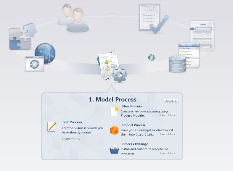
Вы можете использовать один из трех способов моделирования бизнес-процесса:
- New Process — создать свой новый бизнес-процесс;
- Import Process — импортировать бизнес-процесс;
- Process Xchange — выбрать готовую модель из базы бизнес-процессов, предложенной компанией Bizagi. Выбрав шаблон, вы можете доработать его под реалии своего бизнеса. Все представленные модели написаны на английском языке.
Созданный в Modeler бизнес-процесс вы можете редактировать, сохранить, экспортировать в различных форматах (pdf, html).
Моделирование бизнес-процесса производится в формате BPMN 2.0. Этот формат несколько отличается от известного многим BPMN 2.0, я с этим столкнулся на практике. Некоторых возможностей, которые подразумеваются в BPMN 2.0 и в некоторых других программах, созданных для работы исключительно с моделированием, в формате Bizagi вы не найдете. Например, здесь нет так называемой “внешней сущности”. Зато в Bizagi имеются собственные разработки, которых нет в других системах, например, Mailstone — промежуточный этап.
Созданные в Modeler карты бизнес-процессов можно как “расшаривать” на портале Bizagi, так и использовать коллаборатив, то есть несколько сотрудников могут выполнять совместную работу, что очень удобно.
Мodeler имеет русскоязычный вариант интерфейса, в отличие от двух других модулей.
Еще раз напомню, что Modeler предназначен только для моделирования бизнес-процессов. То есть если вам необходим только дизайн бизнес-процесса, этого модуля вам будет достаточно. Если же вам необходимо не только моделировать, но и разрабатывать и исполнять бизнес-процессы, вам понадобится модуль Studio, в котором есть свой моделер бизнес-процессов.
Studio

Смоделированная карта бизнес-процесса должна заработать. Пользователь должен входить в систему и взаимодействовать с различными формами. Studio позволяет разработать интерфейс и формы, с которыми будет работать человек. Ниже мы подробнее рассмотрим все аспекты разработки бизнес-процесса в Bizagi Studio.
Хочу отметить, что Modeler и Studio бесплатны. В базовый пакет Studio включены до 20 тестовых пользователей.
Engine

Engine — это среда исполнения, которая позволяет пользователям заходить в систему и работать в ней, выполняя определенные бизнес-процессы.
Лицензии Engine платные. Бесплатен только тестовый режим.
В Engine предусмотрено два вида лицензии:
- постоянная лицензия;
- лицензия на год.
При этом компаниям, в которых работает до 50 пользователей, предоставляется скидка 50% — это так называемый Starter kit, направленный на поддержку малого и среднего бизнеса. Если на предприятии работает более 50 пользователей, придется оплачивать полную стоимость лицензий.
Engine предполагает пошаговое исполнение разработанного бизнес-процесса с учетом всех прописанных в Studio условий.
Без модуля Engine вы не сможете полноценно работать в системе и исполнять прописанные бизнес-процессы.
Как работает Bizagi
Что мы делаем в Bizagi, если нам необходимо автоматизировать какой-либо бизнес-процесс? Рассмотрим алгоритм действий на примере согласования заявки на расход денежных средств. В статье про BPM-системы мы видели, как этот бизнес-процесс был реализован на реальном проекте посредством учетной системы, сейчас мы посмотрим, как это правильно организовать в системе BPM.
1. Моделирование
Моделирование бизнес-процесса происходит путем перетаскивания графических элементов, предложенных в Bizagi, в рабочую зону.
Выше я писал, что интерфейс Studio, представлен на английском языке, но в самой карте бизнес-процесса мы можем использовать русский язык.
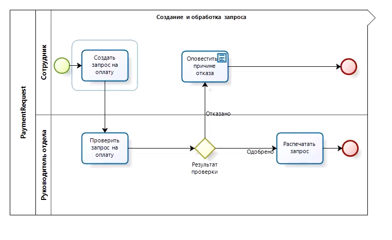
Мы моделируем схему бизнес-процесса Payment Request: определяем начало процесса, события, оповещения, бизнес-правила и конец бизнес-процесса.
Задача заключается в контроле оплаты счетов. Последовательность действий данного бизнес-процесса выглядит так:
1. Сотрудник, которому поступает счет на оплату, должен создать запрос на оплату.
2. Руководитель должен проверить запрос и выбрать один из вариантов действия:
- Отказать;
- Одобрить.
3. При первом варианте Сотрудник получает уведомление об отказе руководителя. На этом бизнес-процесс заканчивается.
3. Во втором случае Руководитель должен Распечатать, подписать запрос и отправить его в бухгалтерию, на этом бизнес-процесс заканчивается.
Графическая карта бизнес-процесса выглядит так:
2. Разработка структуры данных
После того, как бизнес-процесс смоделирован, мы приступаем к разработке структуры данных. На данном этапе мы прописываем, в каких формах, каких полях хранятся те или иные данные и указываем их связи.
В нашем примере мы должны разработать три сущности (Entity):
- Запрос на оплату счета;
- Контрагент (поставщик, которому необходимо оплатить счет);
- Причина отказа.
Для каждой из этих сущностей необходимо прописать атрибуты (поля), которые будут доступны для заполнения. Атрибуты делятся на:
- Предустановленные (их очень много) — атрибуты, которые предлагает сама система;
- Пользовательские — те, которые пользователь создает вручную.
На скриншоте видно, какие атрибуты прописаны для каждой сущности.
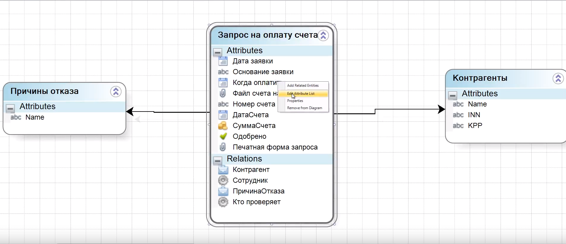
Также необходимо указать связи между этими сущностями. Мы прописываем, что сущности Причины отказа и Контрагенты входят в сущность Запрос на оплату счета.
3. Создание форм (пользовательского интерфейса)
После того, как мы разработали структуру данных, нам необходимо решить, как пользователь заходит в систему, как взаимодействует с ней. И вот здесь нам необходимо создать пользовательский интерфейс.
Когда мы смоделировали бизнес-процесс, мы входим в него и видим, что каждый из этих квадратиков на схеме, обозначающих этапы, — это форма, которую необходимо разработать.
Форма — это то, с чем впоследствии будет работать пользователь.
Хочу обратить ваше внимание на то, что разрабатываются только те формы, над которыми работает пользователь. Если какой-то из этапов предполагает автоматическое действие (например, оповещение Сотрудника об отказе в оплате), для него форму разрабатывать не нужно.
В нашем примере необходимо разработать 3 формы:
- Создания запроса на оплату;
- Проверка запроса на оплату;
- Формирования печатной формы.
Эти формы используют одни и те же данные. Основа в каждой из этих форм одна — запрос на оплату счета. Но каждая следующая форма имеет более расширенный функционал, чем предыдущая. Например, в форме Проверки запроса есть вся информация из формы создания запроса + статус заявки (Одобрено или нет). А следующая форма имеет по сравнению с предыдущей еще и возможность печати запроса. При необходимости ненужные поля из предыдущих форм можно скрыть.
Здесь важно понимать, что это все-таки не одна, а три разных формы. И каждая из них создается заново либо копируется с предыдущей формы, после чего в нее вносятся необходимые изменения.
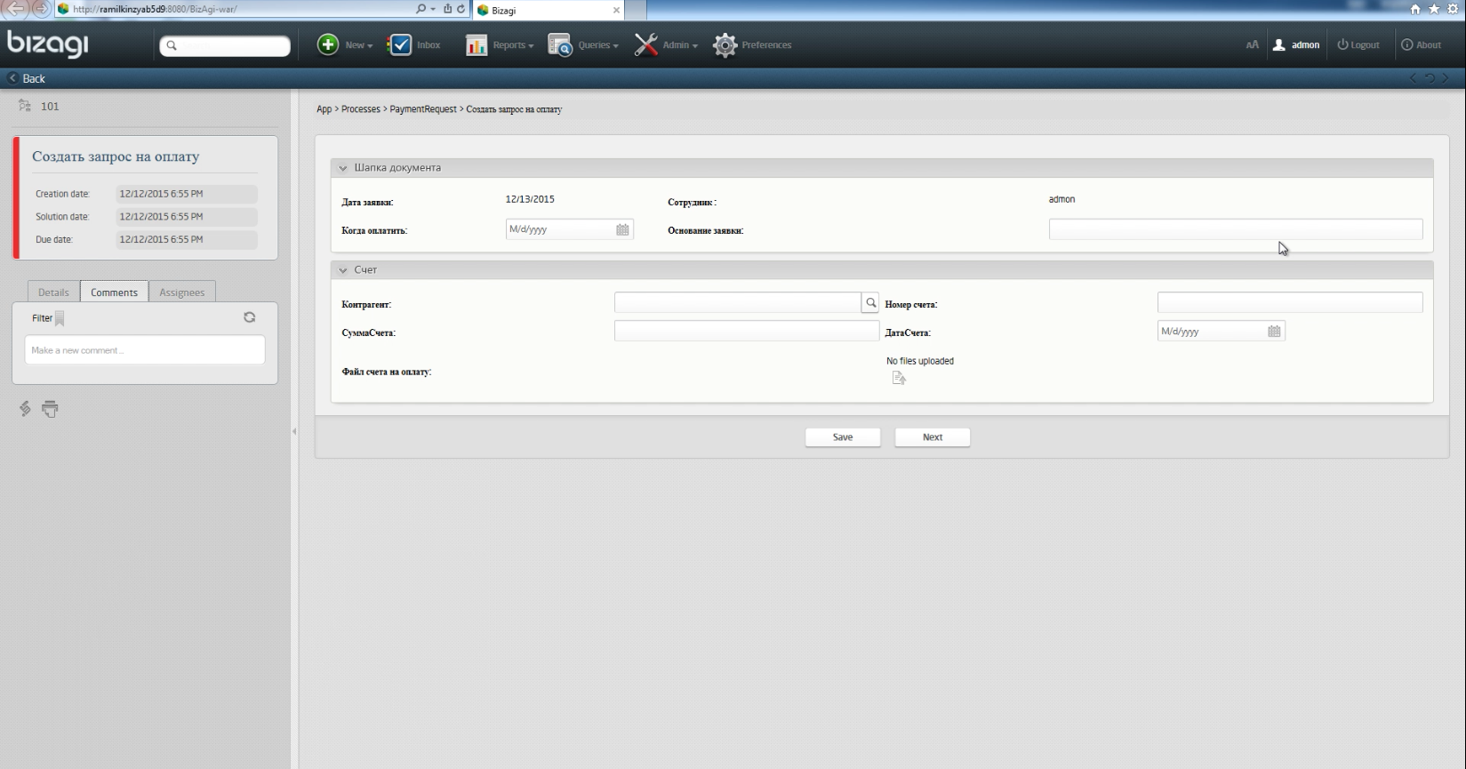
Теперь рассмотрим сам процесс создания формы (например, Создания запроса на оплату).
Форма создается посредством выбора и перетаскивания в активное окно необходимых полей. Для выбора предлагаются поля (атрибуты), которые мы назначили конкретным формам на предыдущем этапе.
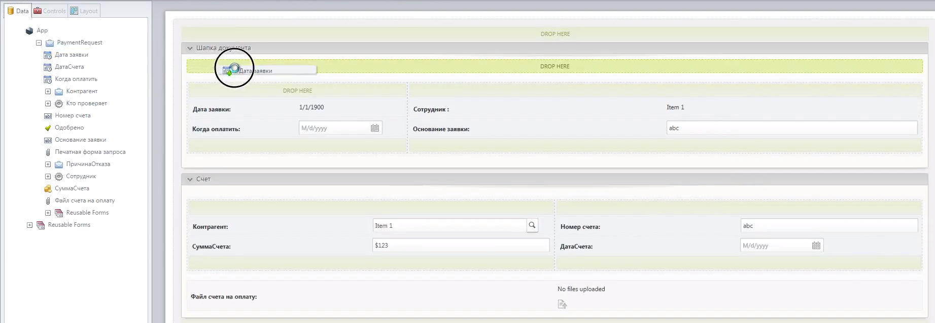
Форма создания запроса в итоге будет выглядеть так:
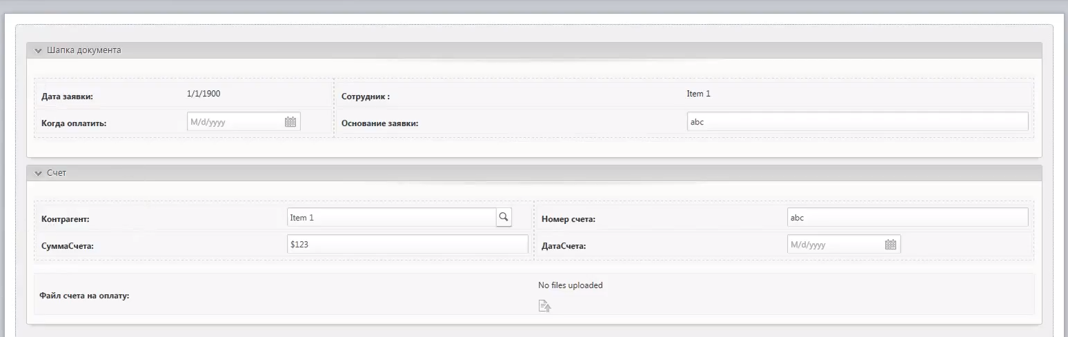
Здесь мы видим поля:
- Срок оплаты;
- Сумма счета;
- Номер счета;
- Контрагент;
- Присоединенный файл (возможно прикрепить счет на оплату).
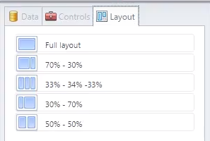
Также для более удобного использования форм можно воспользоваться Layot (варианты расположения частей формы).
Макет формы можно разделить:
- на три равные части (33%-34%-33%);
- на две равные (50%-50%) части;
- на две неравные (70%-30%, 30%-70%) части;
- оставить макет неделимым (Full layout).
На этапе создания форм можно настроить видимость полей и функции редактирования для разных пользователей.
Например, у следующего этапа Проверки запроса есть своя форма, в которой руководителю видны поля, созданные сотрудником на предыдущем этапе, но руководитель эти поля редактировать не может. Зато ему доступны собственные поля, которые не видны сотруднику: поле Одобрено с вариантами Yes/No.
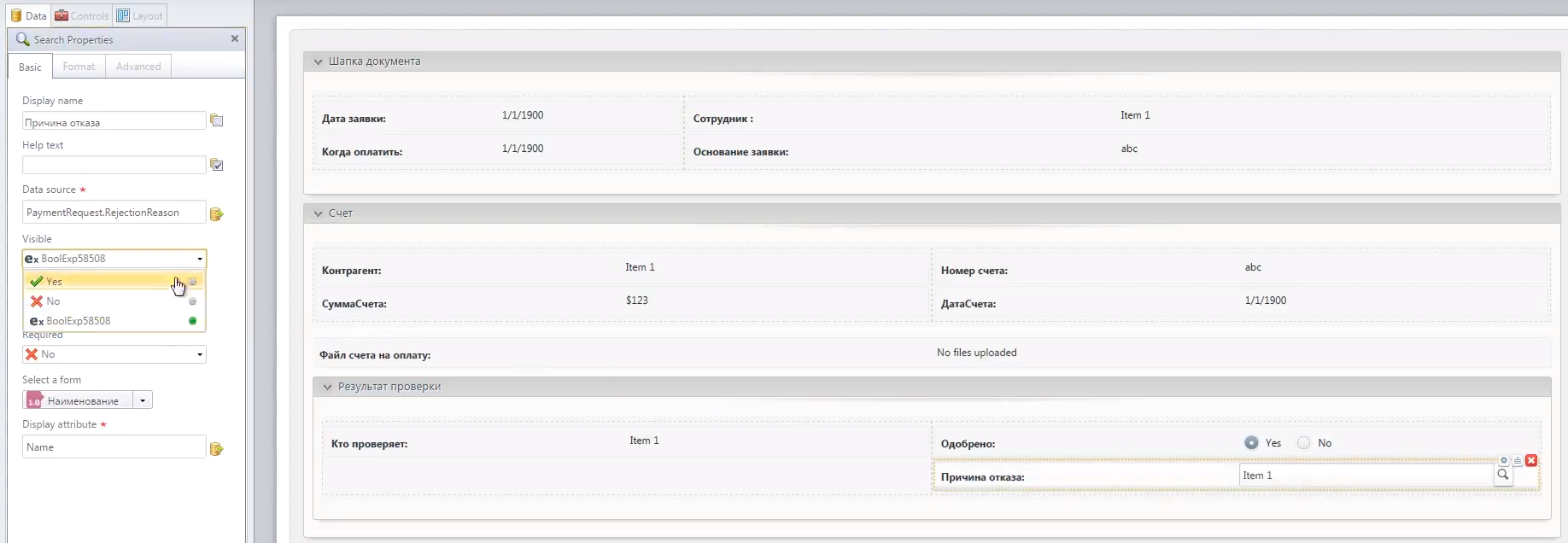
Поле Причина отказа становится видным для руководителя, только если в поле Одобрено он выбрал вариант No. То есть видимость полей можно настроить не только в формате Видно-Не видно, но и в зависимости от каких либо условий. Это условие выглядит так
PaymentRequestApproved is equal to false
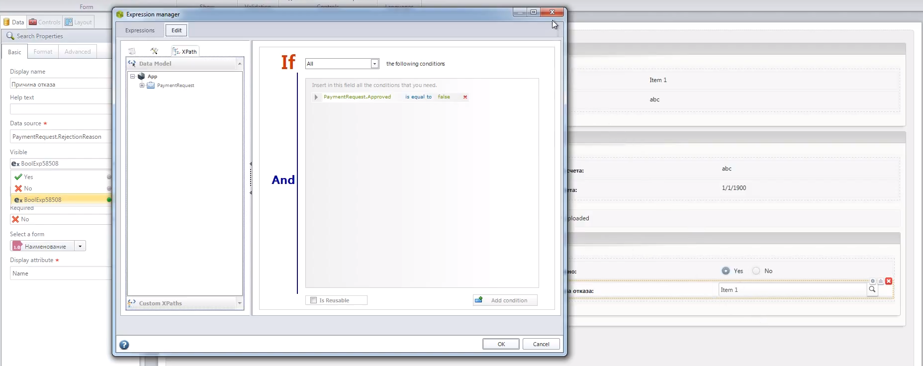
Если Руководитель установил вариант Yes, становится доступной функция распечатать запрос на оплату. Для него уже никакие функции недоступны, кроме Generate template.
4. Определение бизнес-правил
Далее необходимо разработать бизнес-правила, чтобы система автоматически делала некоторые вещи на основании каких-либо данных.
В Bizagi предусмотрено три этапа установки бизнес-правил:
- Define Expressions — предполагает обработку условий
- Activity Actions (Events) — предполагает обработку событий
- Perfomance — предполагает обработку пользователей, работающих на том или ином этапе бизнес-процесса.
Define Expressions
На этапе Define Expressions идет определение вариантов поведения системы при тех или иных условиях. В нашем случае это результат проверки запроса, два варианта (две стрелки), которые ведут от Результата проверки. При нажатии на стрелку, ведущую к следующему этапу, открывается форма, в которых заполняются условия перехода на тот или иной этап.
Если по результатам проверки руководитель отказывает, то процесс переходит в стадию Оповестить о причине отказа.
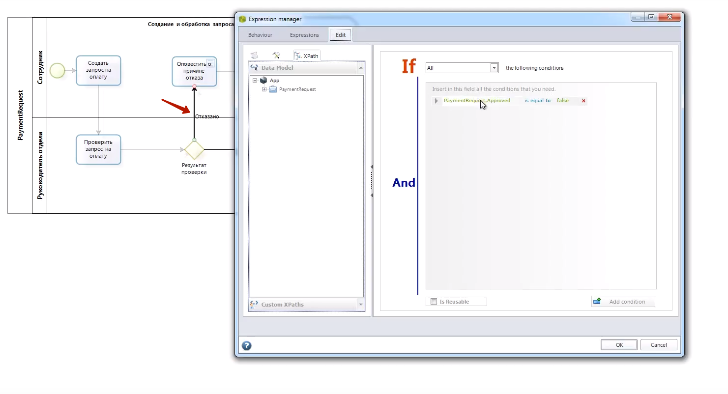
Если по результатам проверки Руководитель одобрил запрос, процесс переходит на этап Распечатать счет.
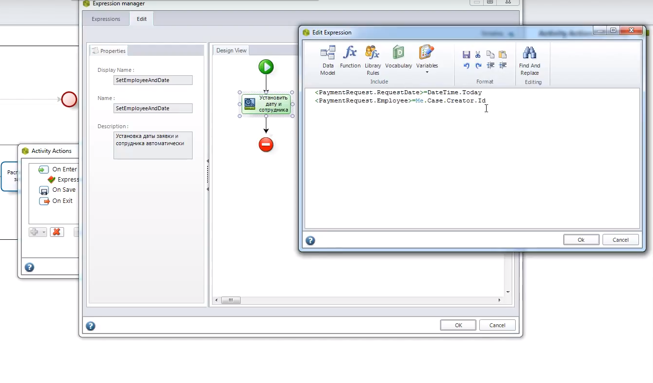
Activity Actions
На этапе Activity Actions мы можем прописать предопределенные поля. Предопределенные поля могут заполняться в трех случаях (на выбор):
- при открытии формы;
- при сохранении;
- при выходе из формы.
Например, на этапе Создания запроса на оплату, мы можем указать, что при открытии формы у нас есть два предопределенных поля:
- Дата — здесь мы указываем, что дата запроса автоматически заполняется текущей датой <PaymentRequest.RequestDate>=DateTime.Today
- Автор (сотрудник) — здесь прописываем, что тот, кто инициировал документ, автоматически становится его автором <PaymentRequest.Employee>=Me.Case.Creator.Id
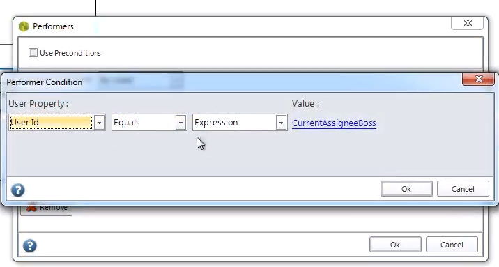
Perfomance
Следующий шаг — это Perfomance. Здесь мы прописываем, кто на каком этапе работает с бизнес-процессом, отвечает за его выполнение.
- На этапе Создания сделки работает сотрудник, создавший эту сделку. User Id Equal Case Creator
- На этапе Проверки запроса работает Руководитель того, кто создал документ. User Id Equals CurrentAssigneeBoss
5. Описание правил оповещения
После того, как мы прописали, как работают бизнес-правила, мы описываем правила оповещения.
Сотрудник не может постоянно находиться в одной системе, у него есть текущие дела и работа в других программах. Как он будет получать информацию об изменениях по бизнес-процессу, которые требуют его участия? Это настраивается с помощью Notification. В BPMN 2.0 есть такое понятие, как notification, и здесь мы можем оповещение привязать к системе.
Оповещения бывают двух видов:
- автоматические (в самой системе есть свой email-сервер) — например, при переходе с одной стадии в другую;
- создаваемые вручную — например, когда пользователь сам хочет отправить сообщение для какого-либо уточнения, но без изменения этапа заявки.
Использовать можно оба вида оповещений одновременно.
В нашем бизнес-процессе при смене этапа (Одобрен или Не одобрен запрос на оплату), Сотруднику отправляется сообщение о том, что счет одобрен или требует уточнения.
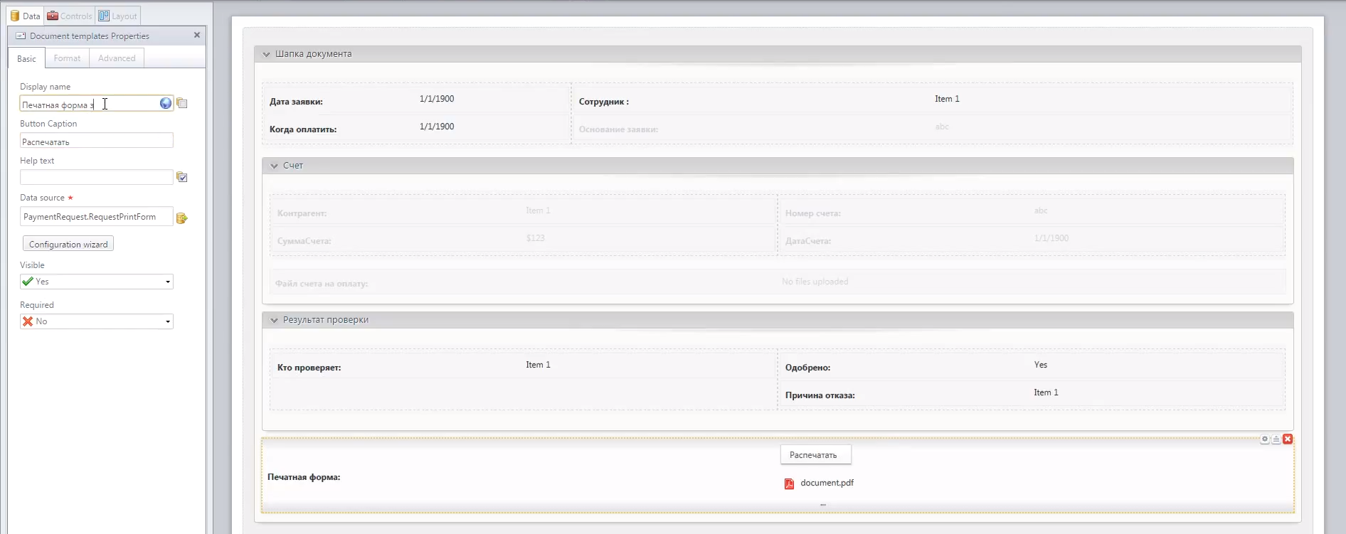
6. Создание печатной формы
В нашем примере сотрудник, кроме электронного документа, хочет получить еще и печатную форму. То есть, если руководитель одобрил запрос на оплату, то он распечатывает, подписывает документ и отдает секретарю для дальнейшей передачи в бухгалтерию. Документ сохраняется не только в системе, но и в печатной форме.
В системе можно создавать, так называемый, document templates. Для печатной формы запроса можно использовать word, excel или простой текст. Мы создали форму, которую должен распечатать тот, на ком заканчивается процесс, и поставить свою подпись. В этой печатной форме видна вся основная информация по запросу:
- Дата создания;
- Пользователь;
- Номер счета;
- Дата счета;
- Сумма счета;
- Основание;
- Подпись ответственного лица.
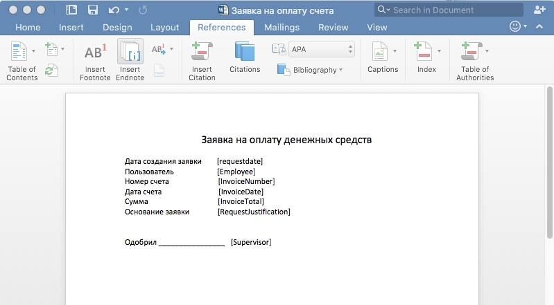
При получении такой формы бухгалтерия сразу может идентифицировать счет, который необходимо оплатить.
Исполнение бизнес-процесса
После того, как мы разработали бизнес-процесс в системе Bizagi, необходимо создать пользователей, указать их структуру, после чего эти пользователи смогут работать в системе.
Рассмотрим, как происходит исполнение созданного нами бизнес-процесса:
Пользователь выбирает бизнес-процесс из тех, что предложены в системе. В данном случае это бизнес-процесс Request Payment. Открывается форма создания запроса.
1. Пользователь заполняет необходимые поля (поле Дата и Автор заполнены автоматически). Пользователь прикрепляет счет на оплату.
2. Руководитель получает оповещение о том, что необходимо Проверить запрос.
3. Руководитель входит в форму запроса, где видит форму проверки запроса с доступными действиями — выбрать, одобрен или не одобрен запрос.
Если руководитель выбрал Yes:
4. Появляется кнопка Generate document для распечатки запроса. Руководитель выводит печатную форму и подписывает ее.
5. Сотрудник, инициировавший запрос, получает уведомление об одобрении счета
Если руководитель выбрал No:
4. Сотрудник, инициировавший запрос, получает уведомление об отказе в оплате счета.
Бизнес-процесс исполнен.
Еще несколько слов о Bizagi
В Bizagi вы всегда сможете посмотреть аналитику по исполнению бизнес-процессов.
В системе предусмотрена интеграция: возможно “снаружи” подключаться к Bizagi, либо из самой Bizagi подключаться к другим программам посредством API. Она использует web-сервисы и SOAP.
Необходимо также напомнить, что система имеет локализацию — варианты на разных языках. Есть в Bizagi Modeler и русский перевод. Сразу скажу, что этот перевод, к сожалению, не всегда правильный. К тому же, вся документация Bizagi представлена только на английском. Поэтому я предпочитаю работать с системой на английском языке.
В заключение хочется отметить, что создание бизнес-процесса — долгая и трудоемкая работа, так как мы пишем практически новое приложение, для которого разрабатываем с нуля структуры данных и формы.

Bizagi Process ModelerUser Guide

2 Copyright © 2013 — Bizagi
Table of Contents
0
Part I Welcome to Bizagi Process Modeler 6
………………………………………………………………………………………………………………….. 61 Overview
………………………………………………………………………………………………………………….. 72 Standards support
………………………………………………………………………………………………………………….. 73 Multi language support
………………………………………………………………………………………………………………….. 94 Training and support
………………………………………………………………………………………………………………….. 105 Related Products
Part II Getting Started 12
………………………………………………………………………………………………………………….. 121 Instal l Bizagi Process Modeler
………………………………………………………………………………………………………………….. 182 System Requirements
………………………………………………………………………………………………………………….. 193 Register to join the community
………………………………………………………………………………………………………………….. 204 Process Modeler fi le types
………………………………………………………………………………………………………………….. 215 User Interface explained
………………………………………………………………………………………………………………………………………. 22Toolbar
………………………………………………………………………………………………………………………………………. 23Ribbon
……………………………………………………………………………………………………………………………………… 36Maxim izing the w orkspace
………………………………………………………………………………………………………………………………………. 37Palette
……………………………………………………………………………………………………………………………………… 37Activit ies
……………………………………………………………………………………………………………………………………… 40Events
……………………………………………………………………………………………………………………………………… 45Gatew ays
……………………………………………………………………………………………………………………………………… 47Data
……………………………………………………………………………………………………………………………………… 47Ar tifacts
……………………………………………………………………………………………………………………………………… 48Sw im lanes
……………………………………………………………………………………………………………………………………… 48Connectors
………………………………………………………………………………………………………………………………………. 48Elem ent proper ties
………………………………………………………………………………………………………………………………………. 49View options
……………………………………………………………………………………………………………………………………… 52Presentation m ode and Presentation actions
………………………………………………………………………………………………………………………………………. 60The Pie Menu
Part III Modeling a Process 62
………………………………………………………………………………………………………………….. 621 Creating a process
………………………………………………………………………………………………………………….. 682 Video example: Creating a process
………………………………………………………………………………………………………………….. 683 Editing a process
………………………………………………………………………………………………………………….. 764 Sub-processes
………………………………………………………………………………………………………………………………………. 80Conver ting to reusable sub-process
………………………………………………………………………………………………………………………………………. 83Sub-process types
………………………………………………………………………………………………………………….. 855 Improving look and feel
………………………………………………………………………………………………………………….. 916 Colors, sizes and shading
………………………………………………………………………………………………………………….. 1057 Printing large diagrams

3Copyright © 2013 — Bizagi
Part IV Documenting a process 111
………………………………………………………………………………………………………………….. 1111 Documenting each element
………………………………………………………………………………………………………………………………………. 113Us ing Rich Text Form at
………………………………………………………………………………………………………………………………………. 120Spelling review
………………………………………………………………………………………………………………….. 1222 Defining Gateway conditions
………………………………………………………………………………………………………………….. 1243 Defining Resources
………………………………………………………………………………………………………………….. 1274 Extending your documentation
………………………………………………………………………………………………………………………………………. 129Extended Attr ibutes type
………………………………………………………………………………………………………………………………………. 131Exam ple: Add a Table Extended Attr ibute
………………………………………………………………………………………………………………………………………. 134Managing Extended Attr ibutes
………………………………………………………………………………………………………………………………………. 134Shar ing Extended Attr ibutes betw een elem ents
………………………………………………………………………………………………………………………………………. 136Expor ting and Im por ting Attr ibutes betw een Models
………………………………………………………………………………………………………………….. 1385 Video example: Documenting your process
………………………………………………………………………………………………………………….. 1386 Using Arti facts
………………………………………………………………………………………………………………….. 1467 Company logo
Part V Generating Documentation 150
………………………………………………………………………………………………………………….. 1501 Publish or Export
………………………………………………………………………………………………………………….. 1512 Publishing in Word
………………………………………………………………………………………………………………………………………. 160Docum ent Tem plate
………………………………………………………………………………………………………………….. 1623 Publishing in PDF
………………………………………………………………………………………………………………….. 1684 Publishing to Web
………………………………………………………………………………………………………………….. 1815 Publishing to Wiki
………………………………………………………………………………………………………………….. 1916 Publishing to Sharepoint
………………………………………………………………………………………………………………….. 2017 Exporting to XPDL
………………………………………………………………………………………………………………….. 2038 Exporting diagrams as Image
………………………………………………………………………………………………………………….. 2069 Exporting to Visio
………………………………………………………………………………………………………………….. 20810 Documentation Portal
………………………………………………………………………………………………………………………………………. 213Creating a Docum entation Por tal (s tep by s tep)
Part VI Importing diagrams 233
………………………………………………………………………………………………………………….. 2331 Import diagram from Visio
………………………………………………………………………………………………………………….. 2382 Import diagram from XPDL
Part VII Simulation 243
………………………………………………………………………………………………………………….. 2431 What is simulation
………………………………………………………………………………………………………………….. 2432 Simulation in Bizagi
………………………………………………………………………………………………………………………………………. 248Sim ulation levels
……………………………………………………………………………………………………………………………………… 251Level 1 — Process Validation
……………………………………………………………………………………………………………………………………… 262Level 2 — Throughput t im e analys is
……………………………………………………………………………………………………………………………………… 273Level 3 — Resource analys is
……………………………………………………………………………………………………………………………………… 292Level 4 — Calendar analys is
………………………………………………………………………………………………………………………………………. 300Scenar ios
………………………………………………………………………………………………………………….. 3033 What If analysis

4 Copyright © 2013 — Bizagi
………………………………………………………………………………………………………………………………………. 305What if analys is exam ple
Part VIII Team Collaboration 312
………………………………………………………………………………………………………………….. 3121 Collaborative process modeling
………………………………………………………………………………………………………………….. 3152 Example of collaboration
………………………………………………………………………………………………………………….. 3203 Video example: Collaboration explained
………………………………………………………………………………………………………………….. 3204 Collaboration levels
………………………………………………………………………………………………………………….. 3225 Offl ine collaboration
………………………………………………………………………………………………………………….. 3256 Confl icts resolution
………………………………………………………………………………………………………………….. 3297 Using Categories
………………………………………………………………………………………………………………….. 3338 User profi les
………………………………………………………………………………………………………………….. 3359 Saving as non-collaborative fi le
………………………………………………………………………………………………………………….. 33610 Force unlock
Part IX Process Execution 340
………………………………………………………………………………………………………………….. 3461 Guidance for automation
………………………………………………………………………………………………………………….. 3502 Video: Bizagi BPM Quicktour
Part X Advanced topics 352
………………………………………………………………………………………………………………….. 3521 Interaction between processes
………………………………………………………………………………………………………………………………………. 356Exam ple: Interaction betw een processes
………………………………………………………………………………………………………………………………………. 359Message Flow connection rules
………………………………………………………………………………………………………………………………………. 360Alignm ent features betw een processes
………………………………………………………………………………………………………………….. 3642 Long lasting transactions
Part XI FAQ 371
………………………………………………………………………………………………………………….. 3711 General FAQs
………………………………………………………………………………………………………………….. 3732 Diagramming and documenting FAQs
………………………………………………………………………………………………………………….. 3783 Sharing documentation FAQs
………………………………………………………………………………………………………………….. 3794 Troubleshooting FAQs
Part XII Process Templates 388
Index 0

Part IWelcome to Bizagi Process Modeler
Copyright © 2013 — Bizagi

6 Copyright © 2013 — Bizagi
1 Welcome to Bizagi Process Modeler
Please refer to the topics on the left or search, to find what you are looking for.
1.1 Overview
About Bizagi Process ModelerBizagi is a business process modeling and documentation tool. The modeler enables you to visually
diagram, model and document business processes in industry-standard BPMN (Business Process
Model Notation). BPMN is a worldwide accepted format for process modeling.
You are able to publish high quality documentation in Word, PDF, Sharepoint or Wiki. Processes can
be easily imported from and exported to Visio or XML, and other tools. The modeler’s Intellisense
(smart code completion) coupled with its unique look and feel allows you to quickly and easily map and
document, without the delay of validation routines.
All processes are saved with a .bpm file extension. Each file is referred to as a model and may contain
one or more diagrams.
A model can refer to a whole organization, a department or a specific process depending on your
needs. Multiple diagrams are positioned as individual sheets (tabs) within your model. You are able
to navigate between diagrams in your model by selecting the associated sheet tab located at the
bottom of the model.
About Process ModelingProcess modeling is a method to analyze, design and diagram a business process flow. Modeling a
process in an iterative, clear, transparent and straightforward way will enable you to understand,

7Copyright © 2013 — Bizagi
analyze and make a positive change to the business process.
1.2 Standards support
Support for BPMN 2.0Business Process Model and Notation, or BPMN, is a graphical notation created to provide a unified
language of worldwide acceptance. It is used to specify business processes, defined by the Object
Management Group (OMG). Bizagi is an active voting member within the OMG.
Bizagi Process Modeler supports the current version, BPMN 2.0.
For more information, see http://www.omg.org/spec/BPMN/2.0
Support for XPDL 2.2The XML Process Definition Language, or XPDL, is a standard format to interchange business process
definitions between different workflow products.
XPDL provides a file format that supports every aspect of the BPMN process definition notation,
including graphical descriptions of the diagram, as well as executable properties used at run time. This
format is standardized by the Workflow Management Coalition (WfMC).
Bizagi Process Modeler supports the current version, XPDL 2.2.
For more information, see http://www.wfmc.org/xpdl.html
1.3 Multilanguage support
The Bizagi Process Modeler is multilingual, and the user interface supports the following languages:
English
Spanish
German
French
Portuguese
Russian
Chinese
Dutch
Italian
Japanese
Install Bizagi Process Modeler in your preferred languageAt the start of the Bizagi Process Modeler installation, you will be prompted to select the language of
your preference. Once selected, all text will be displayed in the chosen language throughout
installation and use of the product.

8 Copyright © 2013 — Bizagi
You can change the language at any time
Once the Bizagi Process Modeler is installed you are able to change the displayed language at any
time. Select a language from the Language drop-down list, located in the upper right corner of the
modeler. For the change to take effect, please restart the Bizagi Process Modeler.

9Copyright © 2013 — Bizagi
1.4 Training and support
The Bizagi Process Modeler offers several types of support to help you with process modeling and
documentation. These are located on the Help tab.
Video Tutorials Learn how to use the Bizagi Process Modeler through short and explanatory videos and discover new
features.
Please refer to our Video Tutorials site
Online training and supportDiscover how to capture and transform a process to benefit your business. We offer self-paced
training courses online free of charge.
Please refer to our e-learning web site
Support Forums We offer free support forms where your questions are answered promptly.
Also, opinions and ideas can be shared with our community that is growing by the day.
To access our support forums you will need to register.
Please refer to our Forums site
Free Process Central Access, download and use our collection of templates containing the best practices of many common
processes used within organizations.
Bizagi process templates are ready to use and executable processes that you can use to boost
ance in your organization. Feel free to customize them to your particular needs.
Again, we welcome your opinion and suggestions, which can be made, once registered.
Please refer to our Process Central
HelpOnline help contains the knowledge you will need to diagram, document and produce your processes.
Feel free to browse through all the documentation. We welcome any of your comments via the
Feedback option.
The user guide can also be downloaded, for offline use, by selecting the Download Help option which
saves the file as a PDF document.

10 Copyright © 2013 — Bizagi
1.5 Related Products
Once you are finished modeling your processes, Bizagi offers the Bizagi BPM Suite to automate your
processes and transform them into an executable system.
Bizagi BPM Suite allows you to enter all the necessary information for process execution: standard
time, costs, user interfaces, business rules, etc. This information is stored as a model in a database and
used at runtime for process execution through a work portal for end users.
With the Bizagi Process Modeler and Bizagi BPM Suite, you have two complementary products that
make up the Bizagi BPM Solution:
Please click for more information about our BPM Suite

Part IIGetting Started
Copyright © 2013 — Bizagi

12 Copyright © 2013 — Bizagi
2 Getting Started
The following chapters will get you started with your Model.
2.1 Install Bizagi Process Modeler
Bizagi Process Modeler is a freeware application that you can download from the internet and use in
a desktop or portable computer.
To install Bizagi Process Modeler run the installer, located on our web portal in Downloads under the
Products menu.
Once loaded, select the language for installation from the drop-down list.
Click the Next button to allow the installation wizard to guide you through the process.

13Copyright © 2013 — Bizagi
To continue, you will need to read the terms of the license agreement.
If you accept the terms, select the I accept the term of the license agreement option and click the Next
button to continue the installation.
Otherwise, select the I do not accept the terms of the agreement option and click the Next button, and
the tool will not install.

14 Copyright © 2013 — Bizagi
Type in your details and then click the Next button.

15Copyright © 2013 — Bizagi
Select the folder where the Bizagi Process Modeler will be installed.
The default folder shown can be changed by clicking the Browse icon, selecting a new folder, and then
clicking the Next button.

16 Copyright © 2013 — Bizagi
Click the Install button to start the installation process.

17Copyright © 2013 — Bizagi
When the installation process is finished, click the Finish button.
A shortcut will be created on your desktop to allow easy access to the application.

18 Copyright © 2013 — Bizagi
2.2 System Requirements
The following are the minimum requirements to install the Bizagi Process Modeler
Operating SystemWindows 8
Windows 7
Windows Vista
Windows Server 2008 R2 / 2008
Windows Server 2003
Note
Windows XP Professional SP3 is supported.
However, consider that support for Windows XP ends on April 8th of 2014 (as Microsoft has officially
announced support for this operating system ends on this date).
SoftwareMicrosoft .NET Framework 4.0 full
Click to download

19Copyright © 2013 — Bizagi
HardwareProcessor: 1 gigahertz (GHz). 32-bit (x86) or 64-bit (x64)
Memory: 1 gigabyte (GB) RAM (32-bit) or 2 GB RAM (64-bit)
Hard drive: 50 MB available hard disk space
Display: 800 x 600 or higher resolution
To view documentationInternet Explorer 9 o 10, Chrome or Mozilla Firefox.
Microsoft Word 2013, 2010, 2007, 2003
Microsoft Visio 2010, 2007, 2003
Microsoft Office Sharepoint Server 2010/2007 and Sharepoint Services 3.0
MediaWiki 1.14 to 1.20 Please see further Wiki requirements
2.3 Register to join the community
When you first open the Bizagi Process Modeler it will prompt you to register.
Although optional, we highly recommend you register in order to obtain the following benefits:
Free Online support
Expert advice
Free documentation
Access to forums
If you are not already a registered user please Register NOW

20 Copyright © 2013 — Bizagi
We respect your privacy. Please review our Privacy policy
2.4 Process Modeler file types
Bizagi Process Modeler has two main file types, differentiated by the file extension:
.bpm, the file format used to save a Bizagi Process Modeler file.
.bpmc, the file format used to save diagrams for Team Collaboration Mode.
Team Collaboration allows for collaborative process improvement and execution. Teams can
participate simultaneously in the definition of a process, thereby enhancing business performance.
Click this link Team Collaboration for further information.
To save a model click Save or Save As on the File tab in the upper left corner or click the disk image
on the Toolbar.

21Copyright © 2013 — Bizagi
2.5 User Interface explained
Bizagi Process Modeler has a very simple, easy and intuitive interface.
It has five main elements; namely, Toolbar, Ribbon, Palette, Element Properties and View.

22 Copyright © 2013 — Bizagi
2.5.1 Toolbar
The Toolbar contains quick access commands to a subset of any menu within the Bizagi Process
Modeler.
The default commands can be customized at anytime.
To adjust the Toolbar click on the drop-down list on the right and select Customize Quick Access
Toolbar which will allow you to add or remove any item.

23Copyright © 2013 — Bizagi
Select a menu option from the drop-down menu and click the Add or Remove buttons to alter to your
preference.
2.5.2 Ribbon
The Ribbon contains the main controls to manage each Process Model. These are organized into
different tabs, and are described below.
Home tab

24 Copyright © 2013 — Bizagi
MENU
OPTIONSUB OPTION DESCRIPTION
Clipboard
PasteInsert the current contents of the clipboard into the
diagram.
CutRemove the selection from the diagram and put it on the
clipboard.
CopyCopy the selection from the diagram and put it on the
clipboard.
Model
Diagrams Open the diagram browser.
Run WorkflowTurn your Process into a running applications. Visit
www.bizagi.com
Online Courses Provide access to E-Learning sites.
ResourcesAdd, edit or remove resources. These are the roles,
systems or people that execute activities.
Validate Check for errors on the active diagram.
Info Show the diagram information.
Team
CollaborationShare Model
Share the model, allowing users to collaborate on the
Process.
Formatting
Font Change the font face.
Font Size Change the font size.
Grow Font Increase the font size.
Shrink Font Decrease the font size.
Editing
Bold Make the selected text bold.
Italic Italicize the selected text.
Underline Underline the selected text.
Strikethrough Draw a line through the middle of the selected text.
Font Color Change the color of the text.
Shading Color the background behind the selected text.
Text alignment Change the color of the text.
Clear Formatting Remove custom formatting, leaving only the plain text.
Find Find text in the model.

25Copyright © 2013 — Bizagi
MENU
OPTIONSUB OPTION DESCRIPTION
Select Select elements in the diagram.
ClearClear formatting from selected elements or delete
selected elements
Review SpellingOpen the spell-check feature to proof text entered in the
process and documentation.
View more information about the Spelling review option.
Discover Bizagi Suite Learn more about Bizagi’s BPM Suite
Format tab
MENU
OPTION
SUB OPTION SUB OPTION
Layout
AlignAlign selected elements. It is possible to align them to
the top, bottom, left and right of the diagram.
Align Horizontal Align the selected items horizontally.
Align Vertical Align the selected items vertically.
Distribute horizontallyDistributes selected elements with even horizontal spaces
between them.
Distribute verticallyDistributes selected elements with even vertical spaces
between them.
Formatting
Font Change the font face.
Font Size Change the font size.
Grow Font Increase the font size.
Shrink Font Decrease the font size.
Bold Make the selected text bold.

26 Copyright © 2013 — Bizagi
Italic Italicize the selected text.
Underline Underline the selected text.
Strikethrough Draw a line through the middle of the selected text.
Font Color Change the color of the text.
Shading Color the background behind the selected text.
Text alignment Align text: center, left and right.
Clear Formatting Remove custom formatting, leaving only the plain text.
View Tab
MENU OPTION SUB OPTION DESCRIPTION
View Lock Locks/ unlocks the diagram for editing (read-only).
Zoom
Zoom In Enlarge the view of the model.
Zoom Out Reduce the view of the model.
ScaleApply a preset zoom level for quick enlargement or
reduction of the diagram (100% default).
100% Show the model at at actual size.
Fit to DiagramScale the page so that the entire diagram fills the viewing
area.
Zoom to selectionScale the page so that only the selected elements of the
diagram fill the viewing area.
PanDisplay a view of the page at a smaller magnification in
order to browse through the diagram.

27Copyright © 2013 — Bizagi
Show/Hide
GridDisplay grid lines for visual reference to aid alignment of
a diagram’s elements.
Black and whiteChange the color mode of the diagram to black and
white.
Presentation actionsHighlight the diagram elements that contain actions in
presentation mode.
Gradient fill
Fill elements with a background color that gradually
changes from one color to another across the surface of
the element.
ShadowsAttach a drop shadow to the element. Shadows are
attached to the bottom-right corner of the element.
Spelling mistakes Highlight the spelling mistakes found in text.
Alignment
Align to gridAutomatically aligns an element to the nearest
intersection of lines in the grid.
Smart alignAutomatically aligns diagram elements to the grid in
relation to one another.
Publish Tab
MENU OPTION SUB OPTION DESCRIPTION
Publish
WordGenerate a Word file of the model and all its
documentation.
PDFGenerate a PDF file of the model and all its
documentation.
WebGenerate a Web file of the model and all its
documentation for web browsing.
SharePoint Export and publishes the model to SharePoint.

28 Copyright © 2013 — Bizagi
Wiki Export and publishes the model to Wiki.
Export / Import Tab
MENU
OPTION
SUB OPTION DESCRIPTION
Export
Image Export the active diagrams as an image.
Visio Export the model as a Visio file.
XPDL Export the model as a XPDL file.
Attributes Save the extended attributes as a XML file.
Import
Visio Create a new diagram based on a Visio file.
XPDL Create a new diagram based on a XPDL file.
Attributes Import extended attributes from a XML file.
Tools tab
MENU OPTION SUB OPTION DESCRIPTION
Tools AttachmentsShow all the attachments in the model: the element to
which the attachment relates and the corresponding file

29Copyright © 2013 — Bizagi
name.
Element CountShow the count of diagram elements by type. The table
displays a list of Processes by name, and the number of
Events, Gateways, Sub-processes and Tasks.
Custom ArtifactsShow the Custom Artifacts Types Manager to create,
edit, delete, export and import custom artifacts.
User ProfileDefine a user profile by which to identify a team member
within a collaborative working model.
Help tab
MENU
OPTION
SUB OPTION DESCRIPTION
Help
Help Displays this User Guide.
Video Tutorials Register Guides you to Bizagi’s video tutorials.
Support Forums Access to the online support forums.
Process CentralAccess to the Bizagi’s Process Central process templates
and discussion forums.
Community
Register Bizagi Process Modeler community registration.
Feedback
Directs you to the Feedback & Questions page to convey
comments, questions, suggestions, and ideas for
improvements.
Tell a FriendA link that enables you to share Bizagi Process Modeler
with clients, colleagues and friends.
AboutRelease Notes Information on the current release.
About Information about Bizagi Process Modeler.
File — Open

30 Copyright © 2013 — Bizagi
MENU
OPTION
SUB OPTION DESCRIPTION
Open Open Model Opens an existing Bizagi Diagram Model.
ImportVisio Creates new diagrams based on a Visio file.
XPDL Creates new diagrams based on an XPDL file.
File — Recent

31Copyright © 2013 — Bizagi
MENU
OPTION
SUB OPTION DESCRIPTION
Recent Recent ModelsQuick access to the latest Bizagi Diagram Models that
have been used.
File — New
MENU
OPTION
SUB OPTION DESCRIPTION
Create ModelBlank Model Creates a new blank model.
Collaboration Model Creates a new blank model in Collaboration Mode. This

32 Copyright © 2013 — Bizagi
mode allows multiple team members to contribute
together to the definition, design and documentation of
a model.
File — Print
MENU OPTION SUB OPTION DESCRIPTION
PrintSelects a printer, number of copies and other printing
options in order to print your diagram.
Quick PrintImmediately prints the active diagram to the default
printer.
Print PreviewOnscreen preview of the diagram in print layout mode,
allowing layout modifications prior to printing.
File — Save & Send

33Copyright © 2013 — Bizagi
MENU OPTION SUB OPTION DESCRIPTION
Send Using E-
Send as
Attachment
Send a copy of the model as an attachment in an e-mail
message
Send as Image Send the model as images in an e-mail message.
Send as XPDL Send the model as an XPDL file in an e-mail message.
Publish
WordGenerate a Word file of the model and all its
documentation.
PDFGenerate a PDF file of the model and all its
documentation.
WebGenerate a Web file of the model and all its
documentation for web browsing.
SharePoint Export and publish the model to SharePoint.
Wiki Export and publish the model to Wiki.
Export to others
formats
Image Export the active diagrams as an image.
Visio Export the model as a Visio file.
XPDL Export the model as an XPDL file.
Attributes Save the extended attributes as an XML file.
Save as
Model File Save the model as a Bizagi Diagram Model file (.bpm).
Team
Collaboration
Save the model as a Bizagi Collaboration Model to a
shared location.
Other Versions
(Model v 1.6)
Export the model to the 1.6 version of Bizagi Modeler
(.bpm).

34 Copyright © 2013 — Bizagi
File — Options
MENU OPTION SUB OPTION DESCRIPTION
General
StyleCustomizes the background color of Bizagi Process
Modeler.
ModeHide or show elements on the drawing palette.
Core will enable only the most common BPMN
elements. Extended will enable all BPMN elements.
Language Change the Bizagi Process Modeler language.
BPMN element
options
Font Define the default font for all diagram elements.
Configure default sizesLaunch the wizard that sets the element’s default
sizes

35Copyright © 2013 — Bizagi
Warn element type
changes
Displays a warning message when an element
changes type. Unintentional change of type may
result in data loss.
MENU
OPTION
SUB OPTION DESCRIPTION
Documentation
Company LogoAllow customization of a user-defined logo, once the
model’s documentation is ready for generation.
Extended attributes Import and export the extended attributes.
Custom Artifacts Create or edit custom artifacts.
Word TemplatesSelect a Word template (.dot file) to generate Word
documentation.

36 Copyright © 2013 — Bizagi
2.5.2.1 Maximizing the workspace
Bizagi allows the Ribbon to be shown or hidden from view.
If you need more room to work, collapse the Ribbon to maximize your workspace and allow the
diagram to fill a larger area of canvas.
For diagrams having a large vertical size (i.e., diagrams containing more than one Pool or many Lanes),
you may choose to rather dock the properties window to the right of the screen (as opposed to the
default location at the bottom of the screen).

37Copyright © 2013 — Bizagi
To relocate and dock the Element properties window, drag and drop it to the desired position. The
location icon highlights to indicate that the window may be dropped in the target position:
2.5.3 Palette
The Palette contains the BPMN graphical elements used to define a process model.
These BPMN graphical elements are described in the following sections:
Activities
Events
Gateways
Data
Artifacts
Swimlanes
Connectors
2.5.3.1 Activities
Activities represent work or tasks carried out by members of the organization. They stand for manual
or automatic tasks performed by an external system or user. Activities can be atomic or non-atomic
(compound) and they are classified into tasks and sub-processes.
Tasks

38 Copyright © 2013 — Bizagi
ELEMENT DESCRIPTION NOTATION
Task
Is an atomic Activity within a Process flow. It is used when
the work in the Process cannot be broken down to a finer
level of detail.
User Task
Is a typical workflow Task where a person performs the
Task with the assistance of a software application.
Service Task
Is a Task that uses some sort of service that could be a
Web service or an automated application.
Receive Task
Is a Task designed to wait for a message to arrive from
an external participant (relative to the Process).
Send Task
Is a Task designed to send a message to an external
participant (relative to the Process).
Script Task
Is a Task that is executed by a Business Process Engine.
The modeler defines a script in a language that the
engine can interpret.
Manual Task
Is a Task that is expected to be performed without the aid
of any business process execution or any application.
Business Rule
Task
Offers a mechanism for the Process to provide input to a
Business Rule Engine and get the output of calculations
that the engine might provide.
Multi-Instance
Loop
Tasks may be repeated sequentially, behaving like a
loop. The Multi-instance Loop iterates a predetermined
number of times. The iterations occur sequentially or in
parallel (simultaneously).
Standard Loop
Tasks may be repeated sequentially, behaving like a loop.
This feature defines a looping behavior based on a
boolean condition. The Activity will loop as long as the
boolean condition is true.

39Copyright © 2013 — Bizagi
Sub-processA sub-process is a compound Activity that is included within a Process. Compound means that it can be
broken down into lower levels, that is, it includes shapes and elements within it.
ELEMENT DESCRIPTION NOTATION
Sub-process
Is an Activity which internal details have been
modeled using activities, gateways, Events, and
sequence flows. The elements has a thin border.
Reusable Sub-
process
Identifies a point in the Process where a predefined
Process is used. A reusable Sub-process is called a
Call Activity in BPMN. The element has a thick
border.
Event Sub-process
A Sub-process is defined as an Event Sub-process
when it is triggered by an Event. An Event Sub-
Process is not part of the normal flow of its parent
Process — there are no incoming or outgoing
Sequence Flows.
Transaction
Is a Sub-process whose behavior is controlled
through a transaction protocol. It includes the three
basic outcomes of a transaction: Successful
Completion, Failed Completion and Cancel
Intermediate Event.
Ad-Hoc Sub-
process
Is a group of activities that has no REQUIRED
sequence relationships. A set of activities can be
defined, but the sequence and number of
performances for the activities is determined by the
resources of the activities.
Standard loop
Sub-processes may be repeated sequentially,
behaving like a loop.
This feature defines a looping behavior based on a
boolean condition. The activity will loop as long as
the boolean condition is true.
Multi-Instance
loop
Sub-processes may be repeated sequentially,
behaving like a loop.
The Multi-instance Loop iterates a predetermined
number of times. The iterations occur sequentially or
in parallel (simultaneously).

40 Copyright © 2013 — Bizagi
2.5.3.2 Events
An Event is something that happens during the course of the Process, affecting the Process flow and
normally has a trigger or result.
To make an event a throw or a catch event, right click on it and select Is Throw. This option will enable
or disable its behavior (applies for certain events described below) .
Start Events
ELEMENT DESCRIPTION NOTATION
Start Event
Indicates where a particular Process starts. It does
not have any particular behavior.
Message Start Event
Is used when a message arrives from a participant
and triggers the start of the Process.
Timer Start Event Is used when the start of a Process occurs on a
specific date or cycle time (e.g., every Friday)
Conditional Start
Event
This type of Event triggers the start of a Process
when a condition becomes true.
Signal Start Event
The start of the Process is triggered by the arrival of
a signal that has been broadcast from another
Process.
Note that the signal is not a message; messages
have specific targets, signals do not.
Parallel Multiple
Start Event
Indicates that there are multiple triggers required to
start the Process. ALL triggers must be triggered
before the Process is instantiated.
Multiple Start Event
This means that there are multiple ways of triggering
the Process. Only one of them is required.

41Copyright © 2013 — Bizagi
Intermediate events
ELEMENT DESCRIPTION NOTATION
Intermediate Event
Indicates where something happens somewhere
between the start and end of a Process. It will affect
the flow of the Process, but will not start or (directly)
terminate the Process.
Message Event
Indicates that a message can be sent or received.
If a Process is waiting for a message and it is caught
the Process will continue its flow.
A catch Message Event waits for a message to arrive
and once the message has been received, the
Process will continue. The Event marker in this
instance will be filled.
A throw Message Event sends a message to an
external participant. The unfilled Event marker is
allocated to the throw message.
Timer Event
Indicates a delay within the Process. This type of
Event can be used within the sequential flow
indicating a waiting time between activities.
Escalation Event
The Event indicates an escalation through the
Process.
Compensation Event
Enables the handling of compensations. When used
within the sequential flow of a Process they indicate
that compensation is necessary.
Conditional Event
This Event is triggered when a condition becomes
true.
Link Event
This Event is used to connect two sections of the
Process.
Link Events can be used to create looping situations
or to avoid long Sequence Flow lines.
If there are two link events on a process (one catch
and one throw) the Modeler will understand they are
linked together. If there is one catch and two throw,
the Modeler will understand both throws are

42 Copyright © 2013 — Bizagi
received by the catch. If there are several catch and
throw events the name of the ‘pairs’ must match for
the Modeler to understand which throw belongs to
which catch.
Signal Event
These Events are used to send or receive signals
within or across the Process. A signal is similar to a
signal flare that is shot into the sky for anyone who
might be interested to notice and then react.
If the Event is used to catch the signal, the signal
Event marker will be filled. Alternatively, the unfilled
Event marker is allocated to the throw message.
Multiple Event
This means that there are multiple triggers assigned
to the Event.
When used to catch the trigger, only one of the
assigned triggers is required and the Event marker
will be unfilled.
Parallel multiple
Event
This means that there are multiple triggers assigned
to the Event. Unlike the normal Multiple Intermediate
Event, ALL of the assigned triggers are required for
the Event to be triggered.
Intermediate Events Attached to an Activity Boundary
ELEMENT DESCRIPTION NOTATION
Message Event
If a message Event is attached to the boundary of an
activity, it will change the normal flow into an
exception flow when a message is received.
If the Event interrupts the activity to which it is
attached, the boundary of the Event is solid, if not it
is dashed.
Timer Event
If a Timer Event is attached to the boundary of an
activity, it will change the normal flow into an
exception flow when a cycle time is completed or a
specific time-date is reached.

43Copyright © 2013 — Bizagi
If the Event interrupts the Activity to which it is
attached, the boundary of the Event is solid, if not it
is dashed.
Escalation Event
If attached to the boundary of an Activity, the
Intermediate Event catches an Escalation.
If the Event interrupts the Activity to which it is
attached, the boundary of the Event is solid, if not it
is dashed.
Error Event
A catch Intermediate Error Event can only be
attached to the boundary of an Activity.
It reacts to (catches) a named Error, or to any Error
if a name is not specified.
An Error Event always interrupts the Activity to which
it is attached, i.e., there is not a non-interrupting
version of this Event. Thus the boundary of the Event
is always solid.
Cancel Event
This Event is used within a Transaction Sub-Process
and must be attached to the boundary of one.
It shall be triggered if a Cancel End Event is reached
within the Transaction Sub-Process. It also shall be
triggered if a Transaction Protocol Cancel Message
has been received while the transaction is being
performed.
A Cancel Event always interrupts the Activity to which
it is attached, i.e., there is not a non-interrupting
version of this Event. Thus the boundary of the Event
is always solid.
Compensation Event
When attached to the boundary of an Activity, this
Event is used to catch the Compensation Event.
When it occurs, the compensation activity will be
performed.

44 Copyright © 2013 — Bizagi
Interrupting a non-interrupting aspect of other
Events does not apply in the case of a Compensation
Event, thus the boundary of the Event is always solid.
Conditional Event
If a Conditional Event is attached to the boundary of
an Activity, it will change the normal flow into an
exception flow when a business condition is fulfilled.
If the Event interrupts the Activity to which it is
attached, the boundary of the Event is solid, if not it
is dashed.
Signal Event
If a Signal Event is attached to the boundary of an
Activity, it will change the normal flow into an
exception flow when a signal is received.
If the Event interrupts the Activity to which it is
attached, the boundary of the Event is solid, if not it
is dashed.
Multiple Event
When attached to the boundary of an Activity, it will
change the normal flow into an exception flow when
one of the assigned triggers is caught.
If the Event interrupts the Activity to which it is
attached, the boundary of the Event is solid, if not it
is dashed.
Parallel multiple
Event
Unlike the Multiple Event, when attached to the
boundary of an Activity, it will change the normal
flow into an exception flow when ALL of the assigned
triggers are caught.
If the Event interrupts the Activity to which it is
attached, the boundary of the Event is solid, if not it
is dashed.
End Events
ELEMENT DESCRIPTION NOTATION

45Copyright © 2013 — Bizagi
End Event
Indicates when the Process ends.
Message End
Indicates that a message is sent when the flow has
ended.
Escalation End Indicates that an Escalation is necessary when the
flow ends.
Error End
Indicates that a named Error should be generated.
All currently active threads of the Process are
terminated. The Error will be caught by a Catch Error
Intermediate Event.
Cancel End
Is used within a Transaction Sub-Process. It indicates
that the Transaction should be canceled and an
alternative flow can be performed.
Compensation End
Handles compensations. If an activity is identified,
and it was successfully completed, the activity will be
compensated.
Signal End
Indicates that a signal is sent when the flow has
ended.
Multiple End
This means that there are multiple consequences of
ending the flow. All of them will occur.
Terminate End
Ends the Process and all its activities immediately.
2.5.3.3 Gateways
Gateways are used to control the divergence and convergence of sequence flows. They determine
ramifications, bifurcations, combinations and merges in the Process. The term “Gateway” implies that
there is a gating mechanism that either allows or disallows passage through the Gateway.
ELEMENT DESCRIPTION NOTATION

46 Copyright © 2013 — Bizagi
Exclusive Gateway
As Divergence: It is used to create alternative paths
within the Process, but only one is chosen.
As Convergence: It is used to merge alternative
paths.
Event Based Gateway
Represents a branching point in the Process where
the alternative paths that follow the Gateway are
based on Events that occur.
When the first Event is triggered, the path that
follows that Event will be used. All the remaining
paths will no longer be valid.
Exclusive Event
Based Gateway
Is a variation of the Event based gateway and it is
only used to instantiate Processes. One the Events of
the Gateway configuration must be triggered in
order to create a Process instance. It must have NO
incoming transitions.
Parallel Event Based
Gateway
Unlike the the exclusive Event based Gateway, ALL
the Events of the Gateway configuration must be
triggered in order to create a Process instance. It
must have NO incoming transitions.
Parallel Gateway
As Divergence: is used to create alternative paths
without checking any conditions.
As Convergence: is used to merge alternative paths,
the gateways waits for all incoming flows before it
continues.
Complex Gateway
As Divergence: is used to control complex decision
points in the Process. It creates alternative paths
within the Process using expressions.
As Convergence: Allow continuing to the next point
of the Process when a business condition becomes
true.
Inclusive Gateway
As Divergence: represents a branching point where
alternatives are based on conditional expressions.
The TRUE evaluation of one condition does not
exclude the evaluation of the other conditions. All
evaluations of a TRUE condition will be traversed by

47Copyright © 2013 — Bizagi
a token.
As Convergence: is used to merge a combination of
alternative and parallel paths.
2.5.3.4 Data
ELEMENT DESCRIPTION NOTATION
Data Objects
Provides information about how documents, data
and other objects are used and updated during the
Process.
Data Store
Provides a mechanism for activities to retrieve or
update stored information that will exist beyond the
scope of the Process.
2.5.3.5 Arti facts
Please click for further information about Artifacts
ELEMENT DESCRIPTION NOTATION
GroupIs an Artifact that provides a visual mechanism to
group elements of a diagram informally.
AnnotationIs a mechanism for a modeler to provide additional
information for the reader of a BPMN Diagram.
ImageEnables an image stored on your computer to be
inserted into the diagram.
HeaderDisplays the diagram properties (author, version,
description), and it is updated automatically with the
information contained in those properties.
Formatted TextThis Artifact enables rich text to be inserted into the
diagram to provide additional information.
Custom Artifacts
Helps to define and use your own Artifacts. Artifacts
provide the capability of showing additional
information about the Process that is not directly
related to the flow.

48 Copyright © 2013 — Bizagi
2.5.3.6 Swimlanes
ELEMENT DESCRIPTION NOTATION
Pool
A Pool is a container of a single Process (contains
the sequence flows between activities).
A Process is fully contained within the Pool. There is
always at least one Pool.
Lane
Is a sub-partition within the Process. Lanes are used
to differentiate elements as internal roles, position,
department, etc. They represent functional areas
that may be responsible for tasks.
Milestone
Is a sub-partition within the Process. It can indicate
different stages during the Process.
2.5.3.7 Connectors
ELEMENT DESCRIPTION NOTATION
Sequence Flow
A Sequence Flow is used to show the order that
Activities will be performed in the Process.
Association
Its used to associate information and Artifacts with
Flow Objects. It also shows the activities used to
compensate for an activity.
Message Flow
Is used to show the flow of messages between two
entities that are prepared to send and receive
them.
2.5.4 Element properties
Element Properties are used to document the process. Each element has its own properties and
depending on the type of element, tabs are displayed with additional information and functionality.

49Copyright © 2013 — Bizagi
The four available tabs are:
Basic: contains the basic information including the name, description and important BPMN
information.
Extended: creates as many elements as required to provide all necessary information to provide for
comprehensive documentation. For further information, refer to Extended Attributes
Advanced: applies specific BPMN attributes to each shape.
Presentation Action: defines what will be displayed in Presentation Mode. For further information
refer to Presentation Actions
2.5.5 View options
On the bottom right corner of the Bizagi Process Modeler are view options that help you to navigate
through your process as is shown in the image below.
This menu can be also found on the View tab of the Ribbon.

50 Copyright © 2013 — Bizagi
Zoom 100%Zooms the model to normal size (100%).
Fit diagramZooms the page so the entire diagram fits in the window.

51Copyright © 2013 — Bizagi
Zoom to selectionZooms the page so the selected elements fit the window

52 Copyright © 2013 — Bizagi
PanShows the pan window which can be used to navigate through the diagram.
2.5.5.1 Presentation mode and Presentation actions
Bizagi allows you to demonstrate your models through the Presentation Mode where a full display
view, in read-only mode is used, similar to the Full screen view in Microsoft products.

53Copyright © 2013 — Bizagi
In Presentation Mode you can access the main characteristics of your processes, all the documentation
you have included and also add Presentation Actions.
Presentation actions are on-click behaviors that can be defined for each diagram element. Behaviors
are additional information that you can add to each element in order to make the process presentation
more complete, for example you can open a URL, a file, an image or display text.
Presentation Mode and Presentation Actions exampleTo illustrate the Presentation mode and actions, our example prresumes that we have finished our
Purchase Request Process and now have to present it to the Purchase Department Manager.
Apart from showing him the process flow and its content we also wish to show the following items in
the presentation:
An associated image of a Purchase Request creation
The Policies for requesting and evaluating quotations
The text contained in the Rejection notification by clicking on the Notify Rejection element.
The following steps illustrate how we created of Presentation actions and the Presentation Actions
Mode.
Include Presentation Actions
1. We need to activate the presentation actions in order to have them displayed in the Presentation
Mode.

54 Copyright © 2013 — Bizagi
On the Home tab, in the Show/Hide group,we select the Presentation Actions checkbox.
2. To include Presentation actions, we need to select the required diagram element.
We right-click on the Create Purchase Request activity and select Properties from the dislay menu.

55Copyright © 2013 — Bizagi
3. On the Presentation Action tab we select Open an image from On Click drop-down list.

56 Copyright © 2013 — Bizagi
4. We click the icon located on the right hand side and upload the Create Purchase Request image.

57Copyright © 2013 — Bizagi
5. Thereafter we follow the same steps to add the Policies file on the Quotations diagram element. But
instead of selecting Open image, we select Open a file.
6. Finally, we add a Show text action for the last item. For this action we type the text needed to be
displayed.

58 Copyright © 2013 — Bizagi
Use Presentation Mode
1. We then click the Presentation Mode button located in the bottom right hand corner of the screen.
Presentation Mode opens a new window, where all processes are read-only. We can browse through
all the documentation including the presentation actions.

59Copyright © 2013 — Bizagi
2. The presentation actions included are displayed as small icons on the side of the element.
Click on an element to display the associated action.

60 Copyright © 2013 — Bizagi
2.5.6 The Pie Menu
The Bizagi Process Modeler has a drag-and-drop feature that allows you to easily diagram your
processes.
The Pie Menu will display as soon as you click on a diagram element that is already in the Process.
Click on the element and drag it to the desired position.
For further information refer to Creating a process

Part IIIModeling a Process
Copyright © 2013 — Bizagi

62 Copyright © 2013 — Bizagi
3 Modeling a Process
Modeling a Process is an iterative and straightforward task to represent business conditions in a flow
diagram, using symbols and shapes.
3.1 Creating a process
You can find the contents of this article in the video: Creating a Process
To explain how you can easily diagram your processes, we will use a Purchase Request Process.
The following are the steps to be carried out in the Process:
A Purchase Request is created
The employee’s Immediate Supervisor (Boss) approves, rejects or changes the request
Quotations are obtained in order to select a Supplier
A Purchase Order is created
The Administrative Manager approves, rejects or modifies the Order
The Purchase Order is sent to the Supplier
The Purchase Order is created in the ERP
As soon as you open the Modeler a Pool will be ready for you to start diagramming.
1. Name your pool. It is usually the name of the process you are about to diagram.
To change the name of the Pool double-click on it, press F2, or right-click on it, and then select Edit
text from the display menu.

63Copyright © 2013 — Bizagi
2. Add a Lane to include participants in your process.
Drag and drop a lane, for each participant, from the Palette.
In our example, we will select three lanes: One for the Immediate Supervisor (Boss), one for the
Requester and one for the Purchase Department.

64 Copyright © 2013 — Bizagi
3. Include a start point in your process.
Drag and drop a Start event from the Palette

65Copyright © 2013 — Bizagi
4. Continue diagramming your process using the Pie Menu. Select the next element and drag and drop
where you wish to locate it.

66 Copyright © 2013 — Bizagi
5. In order to connect two diagram elements in a sequence flow, select an object from the Pie Menu
and drag it to the second diagram element. They will automatically connected.

67Copyright © 2013 — Bizagi
6. Continue selecting the required shapes until your diagram is complete.
7. To resize the pool, select and drag the appropriate corner of the border.
The following image displays the basic diagram of the Purchase Request process.
This first exercise is meant to show you how to diagram with the drag-and-drop functionality. However,
to better describe the process and meet the required standard, some diagram elements need to be
changed. Please refer to the section Editing a process to continue with this exercise.

68 Copyright © 2013 — Bizagi
3.2 Video example: Creating a process
This video shows how to create a process in the Bizagi Process Modeler
3.3 Editing a process
Once you have diagrammed your process, you may need to change diagram elements, add additional
connections or add more elements to improve and complete it.
We will continue using the Purchase Request Process example, mentioned in the previous section, to
show you how to make these changes easily.
Moving elementsIf you need to move a diagram element from one place to another click on it and drag it to the new
position.
Deleting elementsIf you need to delete a diagram element click on it and press the Delete button.
Change/ Transform elementsThe following image shows the initial Purchase Request process we designed. However, we need to
make some adjustments.
Change the Notification Tasks to Script Tasks, since they are emails automatically sent based on a
decision by the Immediate Supervisor (Boss).

69Copyright © 2013 — Bizagi
The Quotation Task is actually a Sub-process where several activities take place in order to be able
to select a supplier.
The Purchase order Task is also a Sub-process where the Purchase Order is sent to the Supplier and
created in the ERP system.
The modeler allows you to change elements within the same category. You do not need to introduce
another element to the Process, but merely change the existing element.
1. To change the Notification Task to a Script Task, right-click on the diagram element and select Task
Type from the display menu.
Choose the appropriate Task type from the drop-down list, note that once you change the task type
you will lose any information, entered into extended attributes, that has not been shared. You
will only receive a warning message if you select the Warn element type changes checkbox (located in
the Show/ Hide group under the View tab).

70 Copyright © 2013 — Bizagi
2. Follow the same procedure for the other two Notifications Tasks. The following image shows your
progress up to this point.
3. To transform the Quotations Task to a Sub-process, right-click on the Task and select Transform to
sub process from the display menu. Do the same for the Purchase Order Task.

71Copyright © 2013 — Bizagi
When you change an element type, any extended attributes information entered will be lost if it
hasn’t been shared.
To avoid this, select the Warn element type changes to be alerted before changing an element to a
different type, as shown in the image below.
Please click for further information about sharing extended attributes
Adding elements If you need to include a new element, keep in mind you may at anytime use: either the pie menu, or the
Palette elements found at the left hand.

72 Copyright © 2013 — Bizagi
In case you want to include a new element in between of 2 existing ones (which are already connected),
Bizagi will provide an option for modeling agility so that just include the new element and avoid the
need to add further connectors or to delete existing ones.
1. To include a new element between 2 existing ones, drag it from the Palette and into the connector
itself.
Note that the connector will highlight to indicate where the new element can be dropped for Bizagi to
attach it automatically.

73Copyright © 2013 — Bizagi
2. Finally, name your element.
Notice that it will be automatically connected, and it will also create the additional connector to the
other element.

74 Copyright © 2013 — Bizagi
Adding MilestonesMilestones are Sub-partitions of a Process used as reference points. They help the readers understand
the different stages that make up the Process.
We will include three Milestones to determine the state of each activity within the Process.
1. To include a Milestone drag it from the Palette and place it in the Process. Drag and drop two more
Milestones.

75Copyright © 2013 — Bizagi
2. Drag and drop the diagram elements that belong to the Milestone.
3. Finally rename each Milestone by clicking on it, pressing the F2 key, and entering a name.

76 Copyright © 2013 — Bizagi
3.4 Sub-processes
A sub-process is a compound activity that is included within a process. Compound means that it can be
broken down into lower levels, that is each level includes shapes and elements within it.
In the previous section we defined a task called “Quotations”, if you have not already created it as a
sub-process (as we now realize that this task contains many activities) we need to transform the
diagram element and define the sub-process flow.
1. To transform the Task, (in this case Quotations), to a sub-process element, right-click on it and
select Transform to sub-process from the display menu.

77Copyright © 2013 — Bizagi
2. Once the Task has been converted to a sub-process it is necessary to define its related diagram.
Right-click on the sub process element and select the Edit subprocess from the display menu.
3. This will automatically open a new diagram page to include the sub process information.
On this page you can diagram the associated sub-process, just the way we diagrammed the first
process. Just drag and drop the elements as needed and place them where appropriate.

78 Copyright © 2013 — Bizagi
Change the sub-process typeBPMN defines several types of sub-process that respond to particular business needs. By default sub-
processes are created as embedded but you can change the sub-process type anytime.
Once you have created a sub-process element in the diagram right-click on the element and select one
of the following options:
Is transaction
Is ad-hoc
Is Event sub-process
Sub process type -> Reusable sub process

79Copyright © 2013 — Bizagi
Additionally you can define the Loop Type of your process from these three options:
None
Multi-instance, the multi-instance attribute of sub processes allows the creation of a desired number
of activity instances.
Standard, this feature defines a looping behavior based on a boolean condition. The sub-process
will loop as long as the boolean condition is true.
For each loop type there are specific advanced options to configure the process’s behavior.
Advanced properties are located in the Advanced tab from the shapes Properties.
By default sub-processes are created as embedded. In BPMN this type of sub-processes have no
pools or lanes. Embedded sub-processes do not allow you to add any pools or lanes to ensure
conformity with the BPMN standard.
If you need to include pools and lanes you can use Reusable sub-processes that according to the
BPMN standard can include pools and lanes. These type of sub-processes are predefined activities.

80 Copyright © 2013 — Bizagi
That is, they are independent and thus are created individually. Then, they can be related to the sub-
process shape. In BPMN this type of sub-process is called a «Call Activity», in Bizagi Process Modeler
we call them Reusable.
3.4.1 Converting to reusable sub-process
You can convert a default sub-process to a Reusable Sub-process, or Call Activity (in BPMN).
1. Right-click on the Sub-process to convert, choose the Sub-process type option and then click onReusable process.
The diagram element’s border will change to indicate it is now a reusable Sub-process.
If you have already diagrammed the Sub-process you will receive a message alerting to this fact. Click
the Yes button to convert it and keep all the lower level diagram elements.

81Copyright © 2013 — Bizagi
Note: It is important to clarify that a reusable Sub-process calls a separately modeled process.
There are two different ways of creating a call to a reusable sub-process. The Edit Sub-process option
opens an empty diagram workspace and relates it to the shape. Alternatively, you can manually relate
the shape to a predefined diagram.
Let us assume that the Quotations Sub-process is reusable and has not yet been diagrammed .
To create a call for the Sub-process not yet model (i.e., create the detail in a new diagram), use the
Edit Sub-process option by right-clicking the shape:
2. To reference an existing diagram (assuming Quotations detail was created in the previous step),
relate the diagram in the Sub-process properties.

82 Copyright © 2013 — Bizagi
To do this, right-click on the Request Quotations reusable Sub-process element and select Properties
from the display menu.

83Copyright © 2013 — Bizagi
3. The Element Properties add-on window will display. On the Basic tab, in the Process drop-down list,
select the predefined created Diagram.
3.4.2 Sub-process types

84 Copyright © 2013 — Bizagi
ELEMENT DESCRIPTION NOTATION
Sub-process
Is an activity whose internal details have been
modeled using activities, gateways, events and
sequence flows. The element has a thin border.
Reusable Sub-
process
Identifies a point in the process where a pre-
defined process is used. A reusable sub process is
called a Call Activity in BPMN. The element has a
thick border.
Event Sub-
process
A Sub-process is defined as an Event Sub-process
when it is triggered by an event. An Event Sub-
Process is not part of the normal flow of its parent
Process—there are no incoming or outgoing
Sequence Flows.
Transaction
Is a Sub-process whose behavior is controlled
through a transaction protocol. It includes the
three basic outcomes of a transaction: Successful
Completion, Failed Completion and Cancel
Intermediate Event.
Ad-Hoc sub-
process
Is a group of activities that has no REQUIRED
sequence relationships. A set of activities can be
defined, but the sequence and number of
performances for the activities is determined by
the resources of the activities.
Standard loop
Sub-processes may be repeated sequentially,
behaving like a loop. This feature defines a looping
behavior based on a boolean condition. The
activity will loop as long as the boolean condition
is true.
Multi-Instance
loop
Sub-processes may be repeated sequentially,
behaving like a loop. The Multi-instance Loop
iterates a predetermined number of times. The
iterations occur sequentially or in parallel
(simultaneously).

85Copyright © 2013 — Bizagi
3.5 Improving look and feel
This article presents tips and tricks that will aid in improving the look and feel of your diagrams.
Diagramming and naming recommendations It is important that Processes are uniformly described, for the sake of being more easily understood by
users.
Therefore, special care must be taken in the naming and layout of all diagram elements.
The following are best practice recommendations that will make processes more readable and
organized.
All words should be capitalized to aid readability.
Always name Tasks using an infinitive verb, to denote an action being executed e.g.: Create request,
Authorize request, Deliver package.
Name Processes and Sub-processes indicating their main purpose.
Always attempt to lay out the Process model in a left to right direction, as it is an intuitive design
choice for left-to-right readers.
Name Sequence Flows that follow after a decision Gateway. For example, if a gateway is called
«Request authorized?» then the sequence flows are named «Yes» and «No» respectively.
Name non-decision Gateways as well. For example, a Process that contains three parallel Gateways
can be named «Parallel1», «Parallel2», «Parallel3» respectively. This will allow you to easily distinguish
one from another in generated documents.
Move and resize text You can move and resize text in the following elements: Sequence Flows, Events, Sub-processes and
Gateways.
To move any of the mentioned text, select and drag-and-drop it where you desire.
To resize the text, select the text and drag the border of the frame.

86 Copyright © 2013 — Bizagi
Reset text positionWhen the text of an element has been repositioned, you can revert it back to its original position by
selecting the Reset text position option on either the element, or the text itself.
In the following image the Changes required caption was moved too far away from the Sequence Flow it
references.
To revert to its original position, right-click the Sequence Flow and select Reset text position.
Note that this option is available at the text (caption) as well:

87Copyright © 2013 — Bizagi
Fit to text In the course of modeling your diagrams, you may come across a situation where the element is much
bigger than the text within it and you need to make it fit the text. A similar situation may arise where
the horizontal space of the element is smaller than the text within it, causing the text outside the object
boundary to be cut off. You can manually drag one of the element’s corners to size or make use of
Bizagi’s Fit to text design shortcut.
To automatically resize the object to fit the text, use the Fit to text option.
Reset to original sizeWhen the size of an element has been changed (either enlarged or shrunk), it can be reverted to its
original size by selecting the Reset size option on the element.
In the following image, the Notify Rejection element was enlarged.
To revert to its original size, right-click the element and select Reset size.

88 Copyright © 2013 — Bizagi
Using the gridWe recommend always showing the grid to facilitate the alignment of elements.
If you select the Align to Grid option, the modeler will auto-align elements to the grid. Essentially, once
the element is dropped, it snaps to the nearest intersection of lines in the grid.
To utilize this option, in the Show/Hide group of the Home or View tab, check both the Show Grid and
Align to Grid boxes.
Aligning elementsAlign all elements both vertically and horizontally, to present a structured layout of your Process.
Bizagi offers a functionality called Smart Align whereby the sequence flows will be automatically aligned
to each other. To utilize this functionality select Smart Align in the Show/Hide group on the View tab.
The following image shows the process without Smart Align selected.

89Copyright © 2013 — Bizagi
The following image shows the process with Smart Align selected.

90 Copyright © 2013 — Bizagi
Rather than align all Sequence Flows of a diagram, you can also align selected diagram elements to
each other.
Click each elements for alignment while holding down the Shift key. In the Layout group of the Format
tab, click Align Horizontal or Align Vertical according to your design requirement.

91Copyright © 2013 — Bizagi
Connecting sequence flowsTo connect a Sequence Flow, drag the red circle (which coincidentally is the arrow head) onto the
diagram element you want to connect to.
Hover the pointer over the element until the green circle appears indicating that it will connect
correctly.
3.6 Colors, sizes and shading
Bizagi allows you to customize the appearance of your diagrams.
You can modify the text formatting of elements such as size, color and type of fonts. In addition
shading can be added to elements including Pools.
You may choose to predefine default settings for the font style, font size and shape colors, or directly
customize these visual options in each diagram.

92 Copyright © 2013 — Bizagi
Set default settingsTo define the font and color options you want to use by default (for new elements), go to the Main
Options found in the File Tab.
Set default Font and Font sizeIn the File Tab, select Options.
In the BPMN element options section of the new window, select the default font face and size from the
drop-down lists.

93Copyright © 2013 — Bizagi
Click Ok to save the settings and return to the diagram.
Element captions created from this point onwards will use the default font and size.

94 Copyright © 2013 — Bizagi
Note that you may also restore this setting to Bizagi’s default text style and size (Segoe UI, size  by
by
clicking on the Restore option.
Set default size for elementsIn the File Tab, select Options.
In the new window, click Configure default sizes.
To alter the size of an element, you can either do so with the mouse (drag one of the element’s corners
to size), or directly enter the pixels dimensions in the Width and Height fields at the bottom left of the
screen.

95Copyright © 2013 — Bizagi
Click Ok to return to the diagram.
Elements, from this point onwards, will be created with the default size
The default setting will apply to both the Palette and Pie Menu components.

96 Copyright © 2013 — Bizagi
Restore to defaultsTo restore the altered font size (revert to Bizagi Process Modeler’s default, namely Segoe UI, size 8),
use the Restore option in the Options window.

97Copyright © 2013 — Bizagi
Similarly, to restore the element’s size to Bizagi Process Modeler’s default, use Restore all to default
values option.

98 Copyright © 2013 — Bizagi
Customize existing diagramsTo customize a diagram, select the desired format in the Formatting group of the Home or Format
tab.
Text formattingSelect the diagram element, then choose the desired format from the Formatting group. The examples
below show how to change the font style, italicize text and make the text bold.
To change the font face, click the arrow next to the Font combobox, then select the style from the

99Copyright © 2013 — Bizagi
drop-down list. Click the Italic or Underline icon to italicize and bold text respectively.
To change the font color, expand the Font Color drop-down list and select the color of your choice.
For alignment, expand the Align drop-down list and select from Left, Center or Right align.

100 Copyright © 2013 — Bizagi
Shading of elementsIt is possible to change the background color of your diagram, as well as for all elements (this includes
shapes, connectors, Pools, Lanes, or Milestones).
To do this, select the element you wish to customize.
Click the arrow next to Shading to select the Change option. Expand the Change drop-down and select
the appropriate color from the background color palette.

101Copyright © 2013 — Bizagi
Bizagi uses gradient fill by default for these background colors, however you may alter this setting.
For more information about disabling the gradient fill, refer to the sections below.
Restore to default settingsTo clear all formatting and revert to the default style, select the diagram you want to restore and click
on the Clear Formatting icon.
Click on the arrow next to Shading and select the Restore option to revert to the original color.

102 Copyright © 2013 — Bizagi
Disabling Gradient-fill To disable gradient fill in element colors, go to the View tab and locate the Show group.
In this group, you may disable or enable the Gradient option so that the color of the elements (i.e,
Gateways, Tasks, Events and Sub-processes) are not shown/published/printed with a gradient fill.

103Copyright © 2013 — Bizagi
Disabling ShadowsTo disable shadows-styled elements, go to the View tab and locate the Show group.
Under this group, you may disable or enable the Shadows option so that elements such as Gateways,
Tasks, Events and Sub-processes do not show/publish/print the drop shadows.

104 Copyright © 2013 — Bizagi

105Copyright © 2013 — Bizagi
3.7 Printing large diagrams
You can print large diagrams by customizing the print settings of the diagram. You can set the paper
size, scales, margins, number of pages, among other things.
To illustrate how to print large diagrams we will use the Personal Loans Request process that you can
find in our free Process Central. This is a complex process where the length makes it a perfect example
for using customized print settings.
It is necessary to change the Printing default settings by following the steps described below.
1. On the File tab, in the Print option, select Print Preview.
The diagram is displayed over several pages. Thus the default settings are not suitable for immediate
printing.

106 Copyright © 2013 — Bizagi
2. In the Page Setup group, click the arrow below Size and select the desired size option. Choose the
paper size, which you will use to print the diagram on, from the list of available sizes.

107Copyright © 2013 — Bizagi
3. In the Page Setup group, click the arrow below Orientation and select either Portrait (vertical) or
Landscape (horizontal).
In this case, since the diagram is long but not too wide we opt for the landscape orientation.
4. On the Page Setup tab, click the arrow below Margins and select the desired Margin from the drop-
down list. We select Narrow margins, in this case, to give the process as much space in each sheet as
possible. You may choose your own customized margins.

108 Copyright © 2013 — Bizagi
5. On the Page Setup tab, click the arrow below Scale and change the diagram scale. The top option
sets a percentage of the normal size of the diagram. Choose the percentage that best fits your
diagram. At the bottom, select the number of pages to fit your diagram on.
As you change the print settings, the diagram will be adjusted and the print preview displayed.

109Copyright © 2013 — Bizagi

Part IVDocumenting a process
Copyright © 2013 — Bizagi

111Copyright © 2013 — Bizagi
4 Documenting a process
Bizagi Process Modeler allows you to document in addition to modeling your processes. You can
include information at process level as well as detailed information at an element (element) level in
your diagram. We recommend the inclusion of all relevant information to make the document readable
and easily understood.
Once your process diagram and documentation is complete, you can publish the documentation in
your preferred format.
For further information please refer to Publish or Export process documentation.
4.1 Documenting each element
Document at process levelThe information included at process level describes the overall process.
By default you can include the following information: Name of the process, description, the version and
the author.
Right-click outside of the boundaries of the pool and select Diagram Properties.
This will enable the Diagram properties add-on window at the bottom of the screen, where you can
include the relevant information.
We recommend to include extended information such as the scope, goal, process owner, important

112 Copyright © 2013 — Bizagi
definitions and any annex. To learn how to include additional information please refer to Extending
your documentation.
Such information may be included with rich-text formatting.
To learn more about this option, refer to Using rich-text formatting.
Document activities and elementsThe information included in each element gives you the possibility to enter detailed information about
each step of your flow.
By default you can include the Name of the element and a complete description. In Activities you can
also include Resources.
1. Right-click on the element you wish to document and select Properties from the display menu.
2. This will enable the Element properties add-on window at the bottom of the screen, where you can
include the relevant information.

113Copyright © 2013 — Bizagi
Insert all relevant information focusing on being as clear, thorough and informative as possible. This is
essential to ensure the document is readable and the process easily understood for successful
execution.
We also advise to include the supplementary information for Activities and Intermediate Events, such as
duration, business rules that resources must comply with and any documentation or forms that are
used.
If you are automating your process we recommend to include the forms that will be displayed to
performers.
To learn how to include additional information please refer to Extending your documentation.
To learn more about process automation please refer to Process Execution.
4.1.1 Using Rich Text Format
While documenting your processes, you may use rich format for the entered text in both descriptions
and extended documentation.
This is, the possibility of having your texts use different font colors, color shading, and styles such as:
bold, italic, underlined, as well as other formatting possibilities such as: indentation and bullets, use of
tables, links and images, amongst others.
This applies for the information contained in descriptions and extended attributes such as Textareas
and Textboxes.
Rich format in descriptionsTo define rich text formatting for your elements descriptions, use the Expand icon located at the right
hand.

114 Copyright © 2013 — Bizagi
This option will open an edition-mode window, in which you may make full use of the rich formatting
options:

115Copyright © 2013 — Bizagi
Rich format in extended documentationTo define rich text formatting for your detail in extended attributes (Textareas, Textboxes), use the
Expand icon.
This icon appears right above the information, when hovering over the extended attribute name.

116 Copyright © 2013 — Bizagi
When clicking on this option, Bizagi will show an edition-mode window, in which you may make full use
of the rich formatting options:

117Copyright © 2013 — Bizagi
Rich formattingYou may include rich text format to your documentation using the following options:
TAB / GROUP DESCRIPTION
Home / Clipboard Handle content by using standard clipboard possibilities: Copy, Cut, Paste
and Paste special
Home / Font Modify: fonts, font size, emphasis (bold, italic,underlined, strikethrough, etc)
and other formatting options such as upper or lower case, and shading
color.
Home / Paragraph Define: alignment, indentation, bullets and numbering, spacing and color fill
options.
Home / Editing Use: Find and replace options to quickly locate your texts.
Insert / Illustrations Include pictures.
Insert / Links Include hyperlinks to Web pages, or to other places in the content.
Insert / Symbol Include symbols from the standard set of characters.

118 Copyright © 2013 — Bizagi
Tables / Table Allows: creating a table with the desired number of rows and columns,
giving quick format, borders and shading to the table, and its rows and
columns.
Tables / Rows and
columns
Handle table modifications by inserting or deleting rows and columns.
Tables / Merge Quickly use powerful options to merge or split cells, or split a table into two
of them.
Tables / Cell size Define the cell size and property for specific cells.
Tables / Alignment Define alignment and margins involved in cells.
Information with rich text format is published in the generated PDF or Word document:
Information with rich text format published in Web:

119Copyright © 2013 — Bizagi
Information with rich text format shown in Presentation mode:
For more information about the generated Web, PDF or Word, and Web documentation, refer to
Generating Documentation.

120 Copyright © 2013 — Bizagi
4.1.2 Spelling review
Bizagi offers a proofing option to check for spelling mistakes while documenting the processes.
To use this feature, locate the Spelling option in the ribbon, at the Home tab.
You may choose a predefined language to be used as the default spelling dictionary directly from its
drop-down options:
Available language dictionaries are:
German (Germany)
English (UK)
English (USA)
Spanish (Spain)
French (France)
Italian (Italy)
Dutch (Nederlands).
Portuguese (Brazil)
Russian (Russia)
To launch the spelling review, click directly on the Spelling option

121Copyright © 2013 — Bizagi
Proofing options are described in the table below.
SPELLING REVIEW OPTION DESCRIPTION
Ignore Ignores the current word and continues proofing the rest of
the information.
Add to Dictionary Adds the current word as a valid word to the given Dictionary.
In this way, the spelling review will not prompt again to correct
these entries.
Reset Dictionary Resets the Dictionary (deletes added entries).
Change Changes the current word for the chosen suggestion.
Change All Changes all occurrences of the current word for the chosen
suggestion.

122 Copyright © 2013 — Bizagi
4.2 Defining Gateway conditions
Gateways represent a branching point in the Process, from which more than one path will be possible
(divergence).
When alternative paths are available from a Gateways (especially for Exclusive or Inclusive types),
documentation is included as conditional expressions for each decision branch representing a path.
In Bizagi, you may define the condition for the path either in the Gateway itself, or in each of its
decision branches (or sequence flow).
Defining conditions in the gatewayTo define the conditions to be met for the given path, open the Gateway properties and locate the
Advanced tab.
For each of the outbound paths at the Gateway (i.e, .each decision branch), you will find a
corresponding row in the Gates table, identified by the branch name (caption).
You may either define a conditional expression for the selected path, or designate it as the Default
path.
Note the visual representation of a default path is a small oblique line crossing the decision branch.
Defining conditions for each sequence flowTo define the conditions which must be met for each path in a Gateway, right-click on the sequence
flow representing the path.

123Copyright © 2013 — Bizagi
In the options displayed you may easily set that this sequence flow is to be taken as the default path by
clicking on Is Default (marking this property)
The Edit condition option provides quick access to the expression editor to create a condition for this

124 Copyright © 2013 — Bizagi
path.
4.3 Defining Resources
A Resource is a Business Entity (e.g. a company, company division, a customer) or a Business Role (e.g.
a buyer, a seller, a credit analyst), which controls or is responsible for a business process or a business
activity.
Resources are part of the basic Element properties provided by default. In each shape they are
identified as Performers, since they are the ones taht actually perform the task. They can be defined for
the whole Pool and for each Activity (Task or Sub-process).
To define, edit or remove Process Performers click on the Performers icon located on the Home tab.
This will display the Performers pop-up window.

125Copyright © 2013 — Bizagi
Click the Add button to create a new Resource.
Click the Edit button to edit.
Click the Delete button to delete.

126 Copyright © 2013 — Bizagi
Enter the name, description and type (Role or Entity) of the Resource.
Once a Resource has been created, you will be able to select it on any activity.

127Copyright © 2013 — Bizagi
4.4 Extending your documentation
With Bizagi Process Modeler you can extend your documentation to include any type of information
that you find relevant for your processes, through extended attributes.
Extended attributes are used to customize your documentation by adding to the basic attributes which
is the default option.
You can include extended attributes in each element of the process.
Once you have created an extended attribute, it will be available for all elements of the same type.
Include Extended AttributesIn order to better explain how you can easily include extended attributes, we will add a Duration
attribute to all Tasks in our Purchase Request process.
As Duration is an integer numeric data type, we will use a Number attribute.
1. Select and right-click on the Task where you want to create the extended attribute, then select
Properties from the display menu.
Select the Extended Attributes tab on the Element properties in the newly displayed add-on window.

128 Copyright © 2013 — Bizagi
2. Click the Add New Extended Attribute link. Provide a name and description, then select Number as
the attribute’s Type.

129Copyright © 2013 — Bizagi
3. Some types have special information that you can add. For Number-type extended attributes you
can add a valid range. In this case we define a duration range of 0 to 500 minutes.
Notice this is the creation of the Extended Attribute only. We have defined a name, its description and
a range. Now, we are able to enter the Duration for each Task.
Use Extended Attributes
Once you have created one Extended Attribute it will be available for all the elements of the same type
in the Model.
On the Extended tab of the Element properties add-on window, enter the information for each element
of the same type as shown in the image below.
4.4.1 Extended Attributes type
Bizagi offers a wide variety of Extended Attribute types. Select and create as many attributes as
required from the following list:
Text Area: stores approximately 32,000 characters, and is used to display long texts with line breaks.

130 Copyright © 2013 — Bizagi
Text Box: stores approximately 32,000 characters, and is used to display short texts, without line
breaks.
Number: stores numbers.
You must define a minimum and maximum range.
Date: stores dates.
Image: stores images with the following extensions: JPG, bmp, PNG and GIF
Single Selection Options (Combo): allows you to define several options to choose from, but only
allows selection of one entry from the drop-down list.
You must define the desired options for selection.
Single Selection Options (Radio): allows you to define several options to choose from, but you can
only check one radio button at any one time.
You must define the desired options for selection.
Multiple Selection Options: allows you to define several options to choose from, and allows
selection of one or more of the check boxes displayed.
You must define the desired options for selection.
Embedded File: allows the modeler to attach a file to be available within the Model. The file is
copied to the model’s folder.
When published this file type and the Linked file will be displayed in the same way.
Linked File: allows you to include a link or path to a file. The model stores a link to the file, not the
file itself.
When including this extended attribute the user must select check/uncheck for the option Relative
path.
Relative path option allows you to include your link either as a relative or absolute path.
Relative paths change depending upon what page the links are located on.
For example, if the file is stored in your computer you would share: C:MyDesktopPurchaseRequest
FileUplodadedInThisExample
If you check on Relative path, then the url will be stored as: PurchaseRequest
FileUplodadedInThisExample.
This way you can share your folder and the file can be opened anywhere.
An absolute path refers to a fixed location including the domain name. You typically use absolute
paths to linked to elements that have a fixed reference location no matter by which means you
access them.
We recommend absolute paths (Relative Path not checked) when the files are on your network.
For example: \MynetworkSharedModelsPurchaseRequestFileUplodadedInThisExample
URL: stores a URL to link an internet resource.
Table: allows you to build a table, including any of the attributes mentioned above.
Click here for an example of a Table Extended Attribute

131Copyright © 2013 — Bizagi
4.4.2 Example: Add a Table Extended Attribute
We are going to include an Extended Attribute where we can document the Performers of each task,
subject to certain conditions.
The performers of the Purchase Request Process are allocated according to purchase amount. This
means that given a certain amount, the purchase will have to be approved and managed differently.
For example the process is different when buying 50 computers to that of purchasing some office
supplies like paper, pens and pencils.
To document this we will use a Table extended attribute where we can define the description of the
performer (name) and a column that will define the amount.
1. Right-click on any Task, select Properties from the display menu and select the Extended Attributes
tab.
Click on the Add New Extended Attribute link.
2. Enter a name and description and select Table as the type
3. Include the columns of the table for the extended attribute.
For this example we will need two columns: the position of the performer and a description.
To add a column use the button.
On the right side of the window enter the name of the column, give a description and select the type.
Since the first column of the table is the name of the performer, we have to define the type of the
attribute as a text box.

132 Copyright © 2013 — Bizagi
4. The second column is the condition to be evaluated, which is the amount of the purchase.
We are going to consider only three options:
Under 1,000 dollars
Between 1,001 and 5,000 dollars
Above 5,001 dollars
Thus this attribute can be defined as a Single Selection Option (combo), this way the modeler will allow
you to choose from one of the above options.
Create the new attribute by clicking on the Add button and select the Single Option (Combo)
type.

133Copyright © 2013 — Bizagi
5. Add the multiple conditions for the modeler to choose from, then click the OK button.
Once you have created this attribute it will be available for all the elements of the same type in
the Model.
Click the Add button located on the bottom of the Element properties window to add records to the
task.

134 Copyright © 2013 — Bizagi
4.4.3 Managing Extended Attributes
You can edit, remove or change the position of your Extended Attributes.
To manage Extended Attributes, select it in the Performers list. A menu will be displayed on the right.
The Edit button allows you to change the type, name and description of your attribute.
The Remove button deletes the attribute. Note, once deleted you can not undo the action.
The Up and Down buttons change the position of the attribute. This defines the order in which they
are generated in your documentation.
The Share button allows you to share the attributes with elements that have different shapes.
4.4.4 Sharing Extended Attributes between elements
Once you have created an Extended Attribute it will be available for all the elements of the same type in
the Model.
It is very common to need an Extended Attribute on several elements of different types.

135Copyright © 2013 — Bizagi
You can share Attributes following the instructions below.
1. Select the diagram element, where the Extended Attribute was previously created, to open its
properties, and select the Extended tab.
Click on the name of the Attribute that you want to share, and click on the share button .
2. Select the structures, among which, you wish to share the Extended Attribute with. In this case we will
share the Performers attribute with the Lane, Manual Task and User Task. After selection, click the OK
button.

136 Copyright © 2013 — Bizagi
4.4.5 Exporting and Importing Attributes between Models
It is possible to share the Extended Attributes that you created in one model and use then in other
models. This allows you to maintain a uniform standard in your documented processes by always
utilizing the information in the same manner.
To do this you will need to export a file from the Bizagi Process Modeler to a chosen folder, where the
extended attributes will be saved. Then import the file to the model where you want those attributes to
be used.
Export Extended AttributesIn the Model where you have defined and created the Extended Attributes you want to reuse, on the
Export/Import tab, in the Export group, select Export Attributes.
Specify the folder where the file will be saved. This folder must have have read and write permissions.
Give your file a valid name and click the Save button.

137Copyright © 2013 — Bizagi
Import Extended AttributesOnce you have saved the Extended Attributes in a file, you can import it to any Model.
On the Export/Import tab, in the Import group, select Export Attributes.
Select the newly created Extended Attributes file. A message will display that you need to read carefully.
If you have some Extended Attributes in the Model into where you are importing, and YOU DON’T
WANT TO OVERWRITE THEM, then click the YES button. Doing so will append the imported Extended
Attributes to the existing Extended Attributes. If you click the NO button, ALL YOUR PREVIOUS
EXTENDED ATTRIBUTES WILL BE REPLACED.

138 Copyright © 2013 — Bizagi
4.5 Video example: Documenting your process
This video shows how to document your processes with Bizagi Process Modeler
4.6 Using Artifacts
Artifacts provide modelers with the capability of showing additional information about the process that
is not directly related to the flow.
Artifacts are found in the Palette. There are five types provided by default, and a user-defined Custom
Artifact.

139Copyright © 2013 — Bizagi
ELEMENT DESCRIPTION NOTATION
GroupAn artifact that provides a visual mechanism to group elements of a
diagram informally. The Group can be used for documentation or
analysis purposes, without impacting process flow.
AnnotationIs a mechanism for a modeler to provide additional information for
the reader of a BPMN Diagram.
To include line breaks in the text use CTRL+ENTER
ImageEnables images stored on your computer to be inserted in the
diagram.
Header Shows the diagram’s properties.
Formatted TextThis artifact enables you to insert a rich text area into the diagram
to provide additional information.

140 Copyright © 2013 — Bizagi
Custom ArtifactA user defined artifact. Artifacts provide the capability of showing
additional information about the process that is not directly related
to the flow.
To include an Artifact select it from the Palette and drag and drop it onto the diagram.
To connect an artifact with an element use the Association Connector.
Some artifacts can be placed on the diagrams using the Pie Menu as shown in the image below.
Click on the element, select the Artifact and then drag and drop it appropriately.

141Copyright © 2013 — Bizagi
Custom Artifacts
You can create your own Artifacts using the Custom Artifact button found in the Palette.
You can attached any stored image onto a Custom Artifact. Browse and select the desired image and
name it. Click the OK button .
Your newly created Custom Artifact will now display in the Custom Artifact group on the Palette.
To include your new Artifact in the diagram, drag and drop the Custom Artifact from the Palette.

142 Copyright © 2013 — Bizagi
Manage Custom ArtifactsTo add, edit or delete Custom Artifacts select Custom Artifacts, located in the Tools group on the Tools
tab.
A new window containing all Custom Artifacts will display for the current Model.
The command buttons located at the bottom of the screen will allow you to manage your Artifacts. The
command buttons are New, Edit, Delete, Export and Import.

143Copyright © 2013 — Bizagi
Exporting and Importing Artifacts between Models
You can share the Custom Artifacts you have created to use them in other models. First you need to
export a file (.bca file extension) to a folder of your choice. Thereafter import the file to the model
where you wish to use the artifacts.
Export Custom ArtifactsIn the Model where you have created the Custom Artifact, select Custom Artifacts, located in the Tools
group on the Tools tab.
Select the Artifact that you wish to share and click the Export button .
Choose the a folder where the file is to reside, name your file and click the Save button. Ensure the
export folder has read and write permissions.

144 Copyright © 2013 — Bizagi
Import Custom ArtifactsOnce you have saved the artifact in a file, you can import it to any Model.
Open the Model where you wish to import the Artifact and select Custom Artifacts, located in the Tools
group on the Tools tab.
Click the Import button.

145Copyright © 2013 — Bizagi
Select the exported file name and click the Open button.
Now your attribute is available to use in the diagram.

146 Copyright © 2013 — Bizagi
4.7 Company logo
Based on feedback from the Bizagi user community there is now an option to remove the Bizagi logo
from the documentation and use your own company logo.
The Bizagi Process Modeler, with its full functionality, is and will stay freeware. If you must remove our
Bizagi logo and thus, remove our marketing mechanism, you will be asked for a small contribution that
will be used to further improve this freeware and benefit the whole community.
To remove the Bizagi logo from your documentation please follow these simple steps:
1. Download the latest Bizagi Process Modeler version (http://www.bizagi.com/index.php?
option=com_content&view=article&id=95&Itemid=107)
2. On the File Tab, select Options and then choose the Documentation option.
3. Click the Configure logo used for documentation link.
4. Click the Buy Now link to purchase the activation KEY. This will take you to the secure Bizagi Online
Shop.

147Copyright © 2013 — Bizagi
5. You will receive a confirmation email with the activation KEY, once your purchase is finalized.
6. Enter the key in the same link window and click the Activate button.
7. A message will display informing of successful validation. Click the OK button.
8. In the last window you will be able to determine the logo you wish to use:

148 Copyright © 2013 — Bizagi
No logo
Keep the Bizagi Process Modeler logo
Use a customized logo
For the customized logo, select Custom Logo and open the folder image to browse and select your
user-defined logo.
9. Click the Close button to finish your configuration.
Important information
You need to buy an Activation Key for each installation (computer) of Bizagi Process Modeler.
For example, if you have the Bizagi Process Modeler installed in 5 PCs, and you need to activate
the logo configuration option in all PCs, then you need to buy 5 Activation Keys.
Just modify the quantity in the shopping cart. You will receive a single Activation Key, which is
valid for the 5 PCs.
The contribution is a one-off payment. The Activation Key will not expire and the logo
configuration option will remain enabled, even if you make updates or upgrades to a new version
of Bizagi Process Modeler.
You will pay on a secure online platform and will receive your Activation Key via email.

Part VGenerating Documentation
Copyright © 2013 — Bizagi

150 Copyright © 2013 — Bizagi
5 Generating Documentation
You can publish your complete documentation in any of the following formats and share with your
organization.
Microsoft Word
Mediawiki
Web file (opened through a browser)
Microsoft Sharepoint
You can export your process diagrams to other Modeling tools or export your customized attributes
and reuse them in other Bizagi Process Models.
Microsoft Visio: export your diagrams to Visio 2003, 2007 and 2010
Image files: export your diagrams to png, bpm, svg or jpg format
XPDL: export your diagram to XPDL 2.1
Attributes: export your customized Extended Attributes and use them in other Bizagi Process Models,
to maintain a standard in your documented processes.
5.1 Publish or Export
Publish your complete documentationYou can publish your complete documentation in any of the following formats and share with your
organization.
Microsoft Word
Mediawiki
Web file (opened through a browser)
Microsoft Sharepoint
Publish All Model and Quick publishFor Word and PDF publishing you can publish all your documentation with just one click.
Publish All Model publishes all the elements in your Model (including all diagrams) with all the
documentation you have defined for each one.
Quick Publish remembers the last time you published and will generate your documentation without
going through the publish wizard. If you have not published before, you will need to go through all
the steps of the publish wizard.

151Copyright © 2013 — Bizagi
Export your diagramsUse this option to export your process diagrams to other Modeling tools or to export your
customized attributes and reuse them in other Bizagi Process Models.
Microsoft Visio: export your diagrams to Visio 2003, 2007 and 2010
Image files: export your diagrams to png, bpm, svg or jpg format
XPDL: export your diagram to XPDL 2.1
Attributes: export your customized Extended Attributes and use them in other Bizagi Process Models,
to maintain a standard in your documented processes.
Click here for more information about Exporting Extended Attributes
5.2 Publishing in Word
You can publish your completed documentation and share it with your organization in Word format.
Customize the output information for inclusion in your document by selecting the diagrams and the
elements to be included.
Bizagi provides an intuitive wizard to help you through the steps to generate your documentation.
1. On the Publish tab, in the Publish group, click Word.

152 Copyright © 2013 — Bizagi
2. Select the diagrams that you wish to publish. Select individually by using the button or select
all by using the button.
When all the diagrams you wish to publish are selected, click the Next button.

153Copyright © 2013 — Bizagi
3. Choose the order in which you wish to publish your diagrams by using the buttons on the right hand
side. Once finished, click the Next button.

154 Copyright © 2013 — Bizagi
4. For each diagram select the elements that you wish to publish in the documentation.
You can select all elements across all diagrams using the button.

155Copyright © 2013 — Bizagi
You can individually select elements from each diagram using the button.

156 Copyright © 2013 — Bizagi
5. For each diagram select the order in which you wish the elements to be exported.
By default elements are organized according to the sequence of the process flow .
To move an element from its default position, select the element and click the button until you
find the desired position.

157Copyright © 2013 — Bizagi
Click the button to order the elements automatically.
When you are satisfied with the order of the elements for each diagram, click the Next button.
6. Select the template you wish to use for your export documentation.
By default the Modeler offers two templates: Bizagi Template with Bizagi’s format (fonts, water marks)
and the Modeler Template with a standard format.
You can create your own user-defined template as well. Please refer to Document Template to learn
how to customize and use your user-defined template. After selecting the template click the Next
button.

158 Copyright © 2013 — Bizagi
7. Specify the appropriate folder in which to publish your process. This folder should have Read and
Write permissions.
By default, the Diagram’s model will be published in a Landscape orientation (only this page).
You may change this setting in this step as well.
Click the Finish button to generate your documentation.

159Copyright © 2013 — Bizagi
8. The Word document will be opened as soon as the documentation is generated with the default
program installed locally to handle .doc files (MS Word, Apache Open Office Writer, etc).

160 Copyright © 2013 — Bizagi
5.2.1 Document Template
Bizagi Process Modeler has two predefined templates for the user to choose from to generate Word
documentation.
BizagiTemplate: this template contains Bizagi’s logo, water marks and styles.
ModelerTemplate: this template has no water marks and uses standard fonts.
You can design and define your own template in Microsoft Office Word to be used when you generate
your Word documentation.
To customize your own template, take the following steps:
1. Use one of the default Templates and amend it as you wish to establish your own documentation
template.
2. Modify your own template.
You may include water marks, new images or modify the styles.
Make sure keep the following styles (you may re-define them):
bizTitle: Used for the document’s title.
bizSubtitle: Used for the document’s subtitle.
Normal / ModelerNormal: Used for general text (i.e, in descriptions). It is used as the default/normal
style.
bizHeading1: Used by the documentation’s title (taken from the file name). Seen in items numbered
as «n».
bizHeading2: Used by the Processes or Sub-Processes chapters. Seen in items numbered as «n.m».
bizHeading3: Used by the Process Elements section. Seen in items numbered as «n.m.o».
bizHeading4: Used by each of the elements. Seen in items numbered as «n.m.o.p».
To modify default styles of the table of contents, modify the TOC1, TOC2, and TOC3 styles.
3. Save the Microsoft Word Document as a Word Template (.dot) in the path where the Modeler was
installed. By default this path is:

161Copyright © 2013 — Bizagi
C:Program FilesBizAgiBizagi Process ModelerTemplates
4. When you generate your documentation in Microsoft Office Word, the wizard will allow you to
choose your template from the list.

162 Copyright © 2013 — Bizagi
5.3 Publishing in PDF
You can publish your completed documentation and share it with your organization in PDF format.
Customize the output information for inclusion in your document by selecting the diagrams and the
elements to be included.
Make sure you have Acrobat Reader installed when you generate this documentation.
Bizagi provides an intuitive wizard to help you through the steps to generate your documentation.
1. On the Publish tab, in the Publish group, click PDF.
2. Select the Diagrams that you wish to publish. Select individually by using the button or select
all by using the button.
When all the diagrams you wish to publish are selected, click the Next button..

163Copyright © 2013 — Bizagi
3. Choose the order in which you wish to publish your diagrams using the buttons on the right hand
side. Once finished, click the Next button.

164 Copyright © 2013 — Bizagi
4. For each diagram select the elements that you wish to publish in the documentation.
You can select all elements across all diagrams using the button.

165Copyright © 2013 — Bizagi
You can also individually select elements from each diagram using the button.

166 Copyright © 2013 — Bizagi
5. For each diagram select the order in which the elements should be exported.
By default elements are organized according to the sequence of the process flow .
To move an element from its default position, select the element and click the button until you
find the desired position.

167Copyright © 2013 — Bizagi
Click the button to order the elements automatically..
When you are satisfied with the order of the elements for each diagram, click the Next button.
6. Specify the appropriate folder in which to publish your process. This folder should have Read and
Write permissions.
By default, the Diagram’s model will be published in a Landscape orientation (only this page).
You may change this setting in this step as well.
Click the Finish button to generate your documentation.

168 Copyright © 2013 — Bizagi
7. The PDF document will be opened as soon as the documentation is generated.
5.4 Publishing to Web
You can publish your completed documentation and share it with your organization in Web format.
Customize the output information for inclusion in your document by selecting the diagrams and the
elements to be included.
You may view the Web documentation from a browser. To review the supported browsers, refer to
the system requirements.
Bizagi provides an intuitive wizard to help you through the steps to generate your documentation.
1. On the Publish tab, in the Publish group, click Web.

169Copyright © 2013 — Bizagi
2. Select individually by using the button or select all by using the button.
When all the diagrams you wish to publish are selected, click the Next button.

170 Copyright © 2013 — Bizagi
3. Choose the order in which you wish to publish your diagrams by using the buttons on the right hand
side. Once finished, click the Next button.

171Copyright © 2013 — Bizagi
4. For each diagram select the elements that you wish to publish in the documentation.
You can select all elements across all diagrams by using the button.

172 Copyright © 2013 — Bizagi
You can also individually select elements from each diagram using the button.

173Copyright © 2013 — Bizagi
5. For each diagram select the order in which you wish the elements to be exported.
By default elements are organized according to the sequence of the process flow .
To move an element from its default position, select the element and click the button until you
find the desired position.

174 Copyright © 2013 — Bizagi
Click the button to order the elements automatically.
When you are satisfied with the order of the elements for each diagram, click the Next button.
6. Specify the appropriate folder in which to publish your process. This folder should have Read and
Write permissions.

175Copyright © 2013 — Bizagi
Once the process has been published on the Web, you will be able to view your diagram
documentation.
WEB OUTPUTGenerated documentation will show your selected processes in an initial Home page.
The description is displayed when the mouse is hovered over each process.

176 Copyright © 2013 — Bizagi
At any time, you may go into the Full screen mode (specially useful to present or view wide diagrams)
by clicking on the Full screen icon located at the top right corner:
Exit full screen mode by pressing the Escape key (ESC) or clicking on the Full screen icon again.
Further documentation included will be displayed when clicking over each element.

177Copyright © 2013 — Bizagi
Click on your process to see the detailed information.
You will be able to see the documentation of any diagram element by clicking on it.
To exit from the details popup, close it or click anywhere else in the diagram.

178 Copyright © 2013 — Bizagi
To perform quick searches on the Process Elements, you may use the search field.
Notice that while searching on the Home page, you will be by default searching over all of your
processes:
To search only in a given process, you may quickly first click on that process:

179Copyright © 2013 — Bizagi
In addition to this, at any time as well, you may use the pan option for quick navigation in the diagram,
or use zoom options which appear at the bottom part of the diagram when hovering the mouse in that
zone:

180 Copyright © 2013 — Bizagi
To go into detail of a Sub-process diagram o to display any of the presentation actions, you may click
on the small icons which appear at the top right corner of shapes, whenever the mouse is hovered on
them:
Presentation actions configured for an element are those same which are set for the presentation
mode:

181Copyright © 2013 — Bizagi
5.5 Publishing to Wiki
Generate your complete process documentation to Wiki format and share it throughout your
organization.
Customize the output information that you want to include in your document by selecting the diagrams
and the elements that will be contained in it.
Make sure you have MediaWiki installed in your server and a user with publishing rights, when you
generate this documentation.
Please review the versions support
Bizagi provides an intuitive wizard to helps you through the steps to generate your documentation.
1. Go to the Publish tab and select Wiki.

182 Copyright © 2013 — Bizagi
2. Select the Diagrams that you wish to publish. Select individually by using the button or you
can select them all by using the button.
When all the diagrams you wish to publish are selected, click on Next.

183Copyright © 2013 — Bizagi
3. Choose the order in which you wish to publish your Diagrams by using the buttons on the right hand
side. When you are finished, click on Next.

184 Copyright © 2013 — Bizagi
4. For each Diagram select the elements that you wish to publish in the documentation.
You can select all elements of all diagrams using the button.

185Copyright © 2013 — Bizagi
You can also choose specific elements from each diagram by using the button.

186 Copyright © 2013 — Bizagi
5. For each diagram select the order in which you wish the elements to be exported.
By default elements are organized according to the sequence of the process flow .
To move an element from its default position, select the element and click on the button until
you find the position you want.

187Copyright © 2013 — Bizagi
Click on the button and they will be ordered automatically.
When you are satisfied with the order of the elements for each diagram, click on Next.
6. The following Information about the Wiki Server will be requested:
Server: URL of your Wiki Server
User and Password: User credentials to access your server. The user must have writing permissions.
NameSpace: To help you differentiate thees process articles from others that are already published
in your wiki, Bizagi allows you to enter a word that will be set before all the created pages.
Category: To help you organize your documentation we recommend that you include a category to
group the pages created in your wiki.
Click on Finish to publish the documentation on the selected server.

188 Copyright © 2013 — Bizagi
Wiki OutputOnce the process has been published on your Wiki, you will be able to see the description of your
diagrams.

189Copyright © 2013 — Bizagi
Click on your process to see the detailed information and elements.
You will be able to see the documentation of any shape by clicking on it.

190 Copyright © 2013 — Bizagi
To perform quick searches on the elements of your process, use the contents table. This will allow you
to quickly see the information of the shapes including basic and extended attributes.
Wiki version supportWe support the following MediaWiki combinations with PHP
Wiki 1.14.x with PHP 5.2.17
Wiki 1.15.x with PHP 5.2.17 and 5.3.10
Wiki 1.16.x with PHP 5.2.17 and 5.3.10
Wiki 1.17.0 with PHP 5.2.17 and 5.3.10
Versions 1.17.1, 1.17.2 y 1.17.3 are not supported

191Copyright © 2013 — Bizagi
Wiki 1.18 with PHP 5.2.17 and 5.3.10
Wiki 1.19 with PHP 5.3
Wiki 1.20 with PHP 5.3
5.6 Publishing to Sharepoint
You can publish your completed documentation and share it with your organization in the SharePoint
format.
Customize the output information for inclusion in your document by selecting the diagrams and the
elements to be included.
Make sure you have SharePoint installed when you generate this documentation. Bizagi supports
SharePoint Services 3.0.
Bizagi provides an intuitive wizard to help you through the steps to generate your documentation.
1. On the Publish tab, in the Publish group, click Sharepoint.
2. Select the Diagrams that you wish to publish. Select individually by using the button or select
all by using the button.

192 Copyright © 2013 — Bizagi
When all the diagrams you wish to publish are selected, click the Next button.
3. Choose the order in which you wish to publish your diagrams by using the buttons on the right hand
side. Once finished, click the Next button.

193Copyright © 2013 — Bizagi
4. For each diagram select the elements that you wish to publish in the documentation.
Select all elements across all diagrams by using the button.

194 Copyright © 2013 — Bizagi
You can also individually select elements from each diagram using the button.

195Copyright © 2013 — Bizagi
5. For each diagram select the order in which you wish the elements to be exported.
By default elements are organized according to the sequence of the process flow .
To move an element from its default position, select the element and click the button until you
find the desired position.

196 Copyright © 2013 — Bizagi
Click on the button to order the elements automatically.
When you are satisfied with the order of the elements for each diagram, click the Next button.
6. The SharePoint Server Information will be required.
The SharePoint site must already be created. You need to provide the location and user credentials to
access it. Then click the Next button.

197Copyright © 2013 — Bizagi
7. Specify the appropriate folder in which to publish your process. This folder must have Read and
Write permissions. Click the Finish button.

198 Copyright © 2013 — Bizagi
Once the process has been published on SharePoint, you will be able to view your diagram
documentation.
SharePoint Output

199Copyright © 2013 — Bizagi
The legend displayed when the mouse is hovered over each process is defined in the Diagram
properties.
All other documentation included will be displayed when clicking over each element.
There are two views available, Mosaic (the default view) and Cover Flow.

200 Copyright © 2013 — Bizagi
Click on your process to see the detailed information.
You will be able to see the documentation of any diagram element by clicking on it.
To perform quick searches on the Process Elements, use the search field.

201Copyright © 2013 — Bizagi
To go back to the general view, click the Home button.
5.7 Exporting to XPDL
The XML Process Definition Language (XPDL) is a format standardized by the Workflow management
Coalition (WfMC) to interchange business process definitions between different workflow products. The
XPDL format can store all aspects of a BPMN diagram, such as attributes, resources, etc. Also some
graphical information is held, for example the coordinates of the elements positions.
Bizagi offers the possibility to share your diagrams with others modeling tools that use BPMN notation.

202 Copyright © 2013 — Bizagi
You can export your diagrams to XPDL using the BPMN 2.0 notation shapes.
For more information about the currently supported XPDL version, refer to Supported standards.
To export your diagrams, follow the steps below:
1. On the Export/Import tab, in the Export group, click XPDL.
2. Specify the appropriate folder to save your XPDL file, this folder need Read and Write permissions.

203Copyright © 2013 — Bizagi
3. After export to XPDL format, you will be able use it in any program that supports this format.
4. You can also import a diagram in XPDL format into the Bizagi Process Modeler.
Click to learn more about importing a diagram from XPDL
5.8 Exporting diagrams as Image
Bizagi Process Modeler allows you to export your diagrams as images, to be opened with any graphic
editor, in the following formats: PNG, bpm, SVG or JPG.
To export your diagrams as images follow these steps.
1. On the Export/Import tab, in the Export group, click Image.

204 Copyright © 2013 — Bizagi
2. Select one of the image formats; namely, PNG, bpm, SVG or JPG. Specify the appropriate folder to
save your image. This folder need Read and Write permissions.

205Copyright © 2013 — Bizagi
3. Click the Save button. Once the diagram has been exported, you will be able to see it in any
graphical editor.

206 Copyright © 2013 — Bizagi
5.9 Exporting to Visio
Bizagi Process Modeler allows you to export your diagrams to Microsoft Visio using the BPMN 2.0
notation shapes.
Bizagi supports Visio 2003, 2007 and 2010.
Make sure you have Microsoft Visio installed when you export your diagrams.
To export your diagrams, follow the steps below:
1. On the Export/Import tab, in the Export group, click Visio.
2. Specify the appropriate folder to save your Visio file, this folder need Read and Write permissions.
Click the Save button.

207Copyright © 2013 — Bizagi
Once the process has been exported to Visio, you will be able to edit and manage the diagram using
the Visio BPMN stencil.

208 Copyright © 2013 — Bizagi
5.10 Documentation Portal
A Documentation portal is a shared repository where people within an organization can access the
company’s processes and related documentation.
The following articles will illustrate how to organize your company’s processes using Bizagi Process
Modeler. With a simple click users can navigate between various levels of detail, from a global view to
the most detailed information of the organization´s processes.
The Documentation Portal can be hosted in a Web portal, using the Publish to Web feature.
It can also be hosted in SharePoint or Wiki. The following example will illustrate the Web portal.
Click here to see a sample Web output of the Documentation Portal

209Copyright © 2013 — Bizagi
How to create a documentation portal
1. Define the structure of processesA defined structure establishes the hierarchy of organizational areas and clarifies how different
processes of the business are classified and interrelated. In addition to the global structure, it is
necessary to define the information to be published and the way in which it will be presented.
Classification and hierarchy of processes
Processes are classified into a hierarchy of categories. Each category represents a company, area, sub-
area, process or any other grouping you define.
For example, in a completely flat organizational structure, if you classify your processes according to
areas it will result in 2 levels. The first will represent areas and the second the processes.
The first level will have as many categories as areas in the organization (each area represents a
category in level 1). The second level will have as many categories as processes in the organization
(each process represents a category in level 2).

210 Copyright © 2013 — Bizagi
The structure and number of levels depends on the layout of each organization and its particular
preferences. As shown, some organizations classify their processes according to areas and sub-areas
(Human resources, Sales, Marketing etc). Process-oriented organizations tend to follow mapping
structure of the ISO 9000 standards and so classify their processes according to pérational function
within the business (strategic processes, operative processes and support processes).
Defining the most suitable structure is essential to provide users an intuitive and logical navigation
through the processes of your organization.
Information of each element
The information to be presented must be planned in advance. For each level define what information
should be displayed and how it will be accessed by final users.
The correct implementation of this step will facilitate understanding of processes within your
organization and ensure proper communication between them.
2. Create the Portal Once the general structure of processes has been defined, you can proceed to organize it in the Bizagi
Process Modeler. The key is to translate the structure previously defined into an interface that allows
users to easily navigate through the processes information.
In the Documentation Portal each category is represented by a page (or tab). On each page you can
define the information for display and the user interface.
Create the Main page
The main page is an overview of the processes areas within the organization. From here viewers can
access company-related information and any of the pages in level 1.

211Copyright © 2013 — Bizagi
Icons to access level 1 pages are included as reusable sub-processes. This way it is possible to link
each icon to the corresponding page.
Additional information can be added by using Artifacts. Aside from improving the look and feel of the
page these elements allow you including links to other sites, pictures and documents.
Create category pages
Recall that a level is composed of categories, where each category is displayed by means of a page;
consequently a level comprises as many as there are categories.
Each category page is created in the same way as the main page, apart from the user interface and
information it displays. Use the reusable sub-process to represent the categories and incorporate
artifacts to include additional information and improve the look and feel.

212 Copyright © 2013 — Bizagi
Information of elements
Once the pages have been designed, it is necessary to configure the information that each Artifact will
display upon selection.
To customize the information, make use of Extended attributes. These attributes can include links to
another sites, images and documents, to name a few.
Link the menus
Once all the levels have been built, link the categories with their associated level. Associate the diagram
(page) from the properties of the corresponding sub-process that represents the category..

213Copyright © 2013 — Bizagi
3. Publish the portal to Web formatOnce the portal has been built in the Bizagi´s Process Modeler, the final step is to publish it. Use the
Web Publish option to define the diagrams and information to be published.
Click here to see a sample Web output of the Documentation Portal
}
5.10.1 Creating a Documentation Portal (step by step)
In the following example we will build a documentation portal step by step.
Let us suppose that the ABC Company has diagramed and documented the following processes:
Recruitment and selection
Expenses report
Help Desk
Travel Request
Access Management
Vacation Leave Request
Accounts payable
Purchase request
In order for processes to communicate and share all their related documentation, the ABC Company
has opted to build a documentation portal. All business processes are diagramed in the Bizagi Process
Modeler and stored in a single .bpm file.

214 Copyright © 2013 — Bizagi
Click here to see the Web output of this Portal
Download here the complete Documentation portal in .bpm format
1. Defining the structure of processes
Classification and hierarchy of processes
The ABC Company concluded that the easiest and most convenient way to classify its processes would
be according to the area in which they are performed. Based on this, the following classification was
established:
Area Process
Human Resources Recruitment and selection
Travel Request
Vacation Leave Request
Financial Expenses report
Accounts payable
Purchases Purchase request
IT Help Desk
Access Management
Note this gives a two-level classification; the first denotes the functional areas and the second the
business processes.
The first level comprise of has four categories (each area represents a category of level 1). The second
level contains eight categories (each process represents a category of level 2).
Level 0 is used to represent the highest level of hierarchy, in this case, the global view of the company.
Information of each element
In this step we have to define what information has to be displayed at which level. The ABC Company
wants different levels of information sharing:

215Copyright © 2013 — Bizagi
Level 0: Company Level
FAQ: Frequently asked questions about the company
Manuals: Documentation on how to use the portal
Contact information: Details of the company contact person if required.
Help: Links to company resources.
Level 1: Areas Level
Area description: A brief overview of the area and its functions.
FAQ: Frequently asked questions about the area
Manuals: Documentation setting out the structure and responsibilities of the area.
Contact information: Details of the contact person for the area, if needed.
Help: Links to area resources.
Level 2: Processes Level
This level will only contain the information of processes.
2. Creating the Portal in Bizagi´s Process Modeler Now that the ABC Company has structured its processes, we can proceed to build the Portal in the
Bizagi´s Process Modeler.
Creating the main page
The first step is to create the page associated with the Level 0 global view (Main page). On this page,
the ABC Company wants to show the different functional areas and some general information on the
organization:
Company logo
FAQ
Manuals
Contact information
Help
The main page should look like this:

216 Copyright © 2013 — Bizagi
Follow the next steps to create the page:
1. Create a new diagram and name it Main page.
2. Remove the Pool shape and include the categories of Level 1, in this case, four sub-processes. Give
each the name of the area it represents.

217Copyright © 2013 — Bizagi
3. Use image artifacts to insert the company logo and add icons to represent the FAQs, Manuals,
Contact us and Help.
4. Customize the appearance of the page using the different options and elements that Bizagi offers
such as modifying shapes colors, using making use of grouping, changing font types etc.

218 Copyright © 2013 — Bizagi
Creating category pages
The next step is to create the level´s pages. In our example, we have two levels. As the lowest level is
composed of the processes already diagramed, we only have to create the pages associated with level
1.
As level 1 is comprises four categories, we create four pages, one for each category: Human
Resources, Financial, Purchases and IT. On each page the ABC Company wants to display the processes
associated with the category (area) and the following general information about the area:
Area description
Company logo
FAQ
Manuals
Contact information
Help

219Copyright © 2013 — Bizagi
In the section bellow we ilustrate how to create the page related to the Human resources category. The
remaining three pages are built in the same way.
1. Create a new diagram and name it as the category. Human Resources.
It may help to include numbers or codes to more easily identify to which level the diagram belongs.
2. Right-click the diagram and open its properties. Enter a description of the area.

220 Copyright © 2013 — Bizagi
3. Remove the Pool shape and include three sub-processes to reflect categories of Level 2. Give each
the name of the process it represents.
4. Use image artifacts to insert the company logo and include icons to represent the FAQs, Manuals,
Contact us and Help.

221Copyright © 2013 — Bizagi
5. Add a Header artifact to include information related to the area. Note the header information is the
included in the diagram properties.
6. Customize the appearance of the menu using the different options and elements that Bizagi offers
such as modifying shapes colors, using making use of grouping, changing font types etc.

222 Copyright © 2013 — Bizagi
Information of elements
Once the structure of the pages has been configured we can continue to define each page element will
displayed upon selection.
Sinve we used artifacts (Faqs, Manuals, Contact and Help) we can customize the properties of these
objects to show the information required.
For instance, when viewers select the Manuals element in the main page, three different manuals must
display. To do that we create a table type extended attribute.
Do the following to customize the information displayed in this artifact:
1. Right-click the artifact and select properties.

223Copyright © 2013 — Bizagi
2. In the Extended tab click Add new extended attribute
3. Assign the attribute name and description and select Table as the type.

224 Copyright © 2013 — Bizagi
4. Define the columns to be displayed in the table. Click the (…) icon in the columns field and set the
necessary ones.
5. Next add the information to be displayed, in this case, the instruction manuals.

225Copyright © 2013 — Bizagi
6. Repeat this procedure for all elements on all pages.
Linking the pages
Once all pages have been created, the next step is to link them taking into account their interrelations
and hierarchy. As we saw, categories are represented by sub-processes. In order to connect them,
these sub-processes have to be converted into reusable sub-processes. This way we can easily select
the related diagram (page) from the sub-process properties.
Bellow we will connect the Main page with the functional areas pages.
1. Right-click a category (in this example an area) and convert the shape into a reusable sub-process
as shown below.
The shape borders will widen.

226 Copyright © 2013 — Bizagi
2. Right-click the category again and open its properties. From the Process field select the diagram to
be linked.
In this way, when users click the shape in the Work Portal the associated diagram will open.
Repeat this procedure to link all the diagrams to pages in the Portal.
3. Publish the portal to web formatOnce built, the Documentation Portal can be exported to the Web as a HTML file to share with other
users within the organization.
To publish your Portal, do the following:
1. On the Publish tab, in the Publish group, click Web.

227Copyright © 2013 — Bizagi
2. Select diagrams individually by clicking the button or select all with the button.
When all the diagrams you wish to publish are selected, click the Next button.
3. Choose the order in which you wish to publish your diagrams by using the ordering buttons on the
right-hand side. Once finished, click the Next button.

228 Copyright © 2013 — Bizagi
4. For each diagram select the elements that you wish to publish in the documentation and click Next.

229Copyright © 2013 — Bizagi
5. Specify the appropriate folder in which to publish your process. This folder should have Read and
Write permissions.

230 Copyright © 2013 — Bizagi
Once the process has been published on the Web, you will be able to view your Documentation Portal.
Click here to see the Web output of this Portal

231Copyright © 2013 — Bizagi
Download here the complete Documentation portal in .bpm format

Part VIImporting diagrams
Copyright © 2013 — Bizagi

233Copyright © 2013 — Bizagi
6 Importing diagrams
Bizagi Process Modeler allows you to import diagrams from:
Microsoft Office Visio or
XPDL format files.
Importing existing models will enhance agility and continuous process improvement efforts.
You can also import the Extended Attributes that you created in a previous model and use then in your
current model.
We highly recommend using the same Extended Attributes within all your models. This allows you to
maintain a uniform standard for all your documented processes.
Click here for more information about Extended Attributes
Click here for more information about Importing Extended Attributes
Why do you need to import?Process diagramming requires a lot of dedication. Organizations often devote a significant amount of
time and resources to it, and may use several diagramming tools.
If this is the case and you have existing diagrammed Processes, all that valuable work will not be
wasted. You can import your diagrams to the Bizagi Process Model and seamlessly continue to
diagram and document.
6.1 Import diagram from Visio
Microsoft Office Visio is a very common tool for diagramming processes. Bizagi Process Modeler
allows you to import such processes to enable editing and manipulation.
To import diagrams from Visio, follow the steps below:
1. On the Export/Import tab, in the Import group, click Visio.

234 Copyright © 2013 — Bizagi
2. Select the stencil used in Visio to diagram the process.
If you click on the Mapping option, you will see the similarity between each of the elements used in the
Visio Stencil and those of the Bizagi Process Modeler.

235Copyright © 2013 — Bizagi
3. Click the OK button and upload the Visio file to be imported.

236 Copyright © 2013 — Bizagi
4. You will be able to modify the process in the Bizagi Process Modeler after import.
Supported Stencils
The stencils that are currently supported are those shown below:
For each stencil, you may review which elements are supported and how are they mapped in Bizagi:

237Copyright © 2013 — Bizagi
You will need to ensure that your Visio model uses one of this stencils instead of “EPC Diagram
shapes”.

238 Copyright © 2013 — Bizagi
6.2 Import diagram from XPDL
The XML Process Definition Language (XPDL) is a format standardized by the Workflow management
Coalition (WfMC) to interchange business process definitions between different workflow products. The
XPDL format can store all aspects of a BPMN diagram, such as attributes, resources, etc. Also, some
graphical information is held, for example position coordinates of the elements.
Using XPDL in Bizagi offers the possibility to share your diagrams with other modeling tools that use
BPMN notation. You can import your diagrams to XPDL using the BPMN 2.0 notation shapes.
For more information about the currently supported XPDL version, refer to Supported standards.
To import your diagrams follow the steps below.
1. On the Export/Import tab, in the Import group, click XPDL.

239Copyright © 2013 — Bizagi
2. Browse and select the XPDL file and click the Open button.

240 Copyright © 2013 — Bizagi
3. The XPDL file load and you can edit it in the Bizagi Process Modeler. It will appear as if the diagram
was created directly in the Bizagi Process Modeler.

241Copyright © 2013 — Bizagi

Part VIISimulation
Copyright © 2013 — Bizagi

243Copyright © 2013 — Bizagi
7 Simulation
Simulation is a tool to evaluate the performance of a model, under different configurations and over long
periods of real time, to reduce the chances of failure to meet specifications, to eliminate unforeseen
bottlenecks, to prevent under or over-utilization of resources (including people and money), and to optimize
system performance. 1
Simulation requires a clear objective to get maximum value for effort. This objective strongly influences
the level of detail in the required data.
Bizagi Simulation follows BPSim (Business Process Simulation) standard that allows enhancement of
business process models captured in BPMN to support rigorous methods of analysis.
7.1 What is simulation
Experiment definitionRandomness is simulated by the use of probabilities for sequence flows and token routing and also by
using statistical distributions to reflect variability in process times of activities etc. To make sure results
are valid, the simulation needs be run for long enough to yield random behavior without chance
(consider the scenario of tossing a coin or rolling a dice multiple times). Provision should be made to
compare results from the same scenario, but different run lengths or replications.The required run
length to yield usable outcomes depends on the process model structure, amount of variability and the
objective; consequently, a single recommended run length cannot be provided. A replication shares the
same scenario configuration and runs for the same length of time, but uses an alternative random
stream.
ComparisonSimulation is well known for providing what-if analysis capabilities; a single simulation run can provide
valuable insight on the performance of a particular scenario. The simulation of multiple scenarios and
the possibility to compare key outcomes, adds further value and support to decision makers.
1. Introduction to modeling and simulation. State University of New York at Binghamton.
7.2 Simulation in Bizagi
To create an ideal scenario for a Bizagi simulation procedure, it is best to start with a complete
process model; if your diagram is not complete, the outcomes may be unreliable.
We recommend following the four levels of simulation one after another. Each subsequent level
incorporates additional information that adds more complexity, providing a coherent analysis of your
processes. Levels are not interdependent, you may start at any level if you hold the required process
data .
By default the Simulation mode will start at Level one, the first time a Simulation is run for the process
model. It is best practice to start simulation at level one, and progress one level at a time. However. it
is possible to move between levels at any time.
Certain options will be available in the context menu of the ribbon according to the level selected. For

244 Copyright © 2013 — Bizagi
more information about these options, please refer to examples for each level.
For each simulation level follow these steps:
Collect process data for the simulation.
Add the data to the relevant shapes in the diagram.
Interpret and present the outcomes.
1. To simulate your process model, click the Simulation View button on the ribbon. Doing so will
display your process in read-only simulation mode.
2. The shapes that require information will be highlighted according to the simulation level in scope.
Note Bizagi will retain the level you are currently running once you save the model returning to the
Process Model view.

245Copyright © 2013 — Bizagi
3. Select each highlighted shape in turn and enter the information.
4. Once all the data has been added, click Run to launch the Process Simulation window.

246 Copyright © 2013 — Bizagi
5. Click Start to run the simulation. When you run a simulation, it will show an animated view of the
process in execution and the the flow of tokens between the activities.
You may click the Stop button at any time to end the simulation.

247Copyright © 2013 — Bizagi
6. Once the simulation has run, the outcomes will display.
Click Results to view the outcomes.
7. Click the Export to Excel button, located at the bottom left, to transfer the Results chart to Excel.
8. Process to the next level of simulation and repeat step 2-8.

248 Copyright © 2013 — Bizagi
9. To return to the Process Model view, click Close Simulation View.
Save your model for Bizagi to retain the current simulation level, returning to the Process Model view.
For information about how to manage scenarios, please refer to Scenarios
Note: The simulation engine does not support the pattern modeled in Transactional Process, Change
Management and Ad Hoc, from our Process Central.
7.2.1 Simulation levels
Bizagi Simulation comprises of four levels. Each subsequent level incorporates additional information
exhibiting more complexity than the preceding one, thereby providing a detailed analysis of your
processes. Levels are not interdependent, , you may start at any level if you hold the required process
data .
Level 1 — Process Validation: The first and most basic simulation level to evaluate the
structure of the process diagram.

249Copyright © 2013 — Bizagi
Data: It requires estimated percentage splits of sequence flows to provide a basis for routing. It also
needs the value of the trigger counter contained in the Start Event shape.
Results: The outcomes show all paths activated during the execution and whether all tokens actually
finished. Additionally, it evaluates how many tokens passed through each Sequence Flow, Activity and
End Event.
Level 2 – Time Analysis: Second level of simulation to measure the end-to-end process
time.
Data: Apart from the data entered in Process Validation, estimated timings (service times) of each
activity and the interval time between token generation is required. This data can either be constant or
samples from statistical distributions1.
Results: The results show process throughput times for tokens, presented as minimum, maximum,
mean and sum (total of all processing times). Similar results can be presented for individual key
activities.
Level 3 – Resource Analysis: Predicts how the process will perform with different
levels of resources. This level of detail provides a reliable estimate of how the process will perform in
operation.
Data: In addition to the data entered in Time Analysis, this level includes the definition of resources
(and/or roles): how many are available and where they are used. Due to the inclusion of resources, the
activity times should be adjusted to represent the actual work time; delay due to unavailability of staff
will be explicitly indicated.
Results: The structure of the results is similar to Time Analysis. Also, the time spent, the time spent
busy or idle for each type of resource is presented.
This level assume an unlimited number of resources.
Level 4 – Calendar Analysis: Includes calendar information that reflects the process
performance over dynamic periods of time, such as shifts, days schedules or weeks.
By default Bizagi includes a chosen calendar that works 24/7. If no calendars are defined, Bizagi will
assume that the defined Resources will always be available.
Data: Apart from the data entered in Resource Analysis, it includes the definition of resource
calendars.

250 Copyright © 2013 — Bizagi
Results: The structure of the results is similar to Resource Analysis.
EXAMPLE
To better illustrate each of the simulation levels let us consider an Emergency attendance process. In
this process a call center receives a report of an emergency. Upon receiving the call, a call center agent
enters details on the person affected, the symptoms and the physical address where the emergency
occurred.
On receipt of the report, a qualified nurse classifies the emergency according to its severity.
Green: Low severity. The patient can be easily stabilized.
Yellow: Medium severity. The patient requires special attention but can be stabilized at the place of
emergency.
Red: High severity. The patient must be collected and taken to the nearest hospital.
According to the priority assigned, the Emergency attendance department presents a different level of
response.
Green: This triage is assisted by a quick response vehicle (i.e. a motorcycle) carrying two people: a
paramedic and a doctor.
Yellow: This triage is assisted by a basic ambulance having a doctor, nurse and a paramedic on
board.
Red: This triage is assisted by a fully equipped ambulance holding two doctors, a nurse and a
paramedic.
If the emergency is green or yellow, the process finishes once the response team arrives at the at the
place of emergency.
If the emergency is red, the fully equipped ambulance transfers the patient to the nearest hospital.
During the transfer a nurse carries out the necessary paperwork to ensure quick admittance.
When the patient arrives at the hospital with the necessary paperwork, the receptionist will be able to
admit the patient quickly and provide medical assistance immediately.

251Copyright © 2013 — Bizagi
This process must be carefully analyzed in order to reduce the time between receiving the request and
providing medical assistance (at the place of emergency or the hospital). Here, time is life. Bizagi
Simulation will help us to make clear decisions to best design the business process and reduce the
emergency wait time.
1. Refer to BPSim specification to review statistical distributions supported and their explanation.
7.2.1.1 Level 1 — Process Validation
OverviewThe first level of the simulation validates the Process Model, making sure the process passes through
all the sequence flows, and behaves as expected.
Resources, processing times and costs are not included in this level. Such parameters will be included
later in subsequent levels.
When validating a Process Model the simulation results will show if:
Gateways are synchronized.
Messages are synchronized.
Decisions probabilities are correctly assigned.
Routing behaves as expected.
All tokens have ended.
Bizagi offers real-time animation of simulations to easily identify problems. The Results report will show
the behavior during execution

252 Copyright © 2013 — Bizagi
Defining the input data required for this levelIn the Process Validation level you will note that only Start Events and Gateways are enabled for
editing. For this level you need to define:
Max.arrival count: Define the number of token instances the process will generate (or trigger).
We recommend defining a large enough number (at least 1000) to allow the execution to stabilize and
present reliable outcomes.
Select the Start Event of the process and click the Gear icon on the pie menu. Enter the Max.arrival
count in the pop-up window.
Note:
The simulation will finish when one of these options happens first: sceario’s duration is reached, max
arrival count is reached.
When you define a scenario duration, (in the scenario´s configuration) the simulation will finish once
this duration is reached, disregarding the Max arrival count.
The same applies the other way around: once the max arrival count is reached the simulation will
finish disregarding the scenario’s duration.
Gateways routing: Inclusive and exclusive Gateways have activation probabilities. Probabilities are
values between 0 and 100%.

253Copyright © 2013 — Bizagi
Select the Gateway and click the scroll arrow icons ( ) to set the probabilities.
If you do not define probabilities for the paths, they will be equally distributed.
Running the simulationOnce the required data for this level have been defined, click the Run button to execute the simulation.

254 Copyright © 2013 — Bizagi
In the new window, click Start to run the simulation.
When running a simulation, the following analysis data will display:

255Copyright © 2013 — Bizagi
Number of completed tokens.
Number of token instances created.
Number of instances that activate each shape.
Number of finished instances.
ResultsWhen the simulation is finished, view the results by selecting the Results option.
For this first level, the results of the simulated outcome will contain the following information:

256 Copyright © 2013 — Bizagi
Name: Identifies the specific BPM shape for which the results are displayed.
Type: Identifies the element type of the BPM shape.
Tokens completed: Indicates how many tokens were processed (instances) during the execution of
the simulation.
You can transfer the results report to Excel by clicking the Export to Excel button.
Example: Validating the Emergency attendance processWe wish to validate the process flow of the Emergency attendance process:

257Copyright © 2013 — Bizagi
Define the required input data for this level, namely the max.arrival count and the probabilities for all
decision Gateways
1. In this example we will generate 1000 token instances. Click the Start Event and then the Gear icon.
Set the control’s value to a 1000.

258 Copyright © 2013 — Bizagi
2. Define the probabilities for all outgoing paths of the Gateway. Suppose the emergency department
has estimated, based on historical data, that the probabilities for the different sequence flows are:
Green: 20%
Yellow: 30%
Red: 50%
Define each probability for the Gateway named Triage type.

259Copyright © 2013 — Bizagi
3. Parallel Gateways always activate all outgoing sequence flows; therefore, it is not necessary to
define probabilities for this Gateway.
4. Click the Run button.
Now, click Start to run the simulation. Note how the number of completed events are displayed in
execution.
When the simulation is complete, select Results.

260 Copyright © 2013 — Bizagi
Analyzing the results The results obtained are:
Analyzing the results we conclude that something is wrong. The number of tokens (1000) created at the
Start Event of the process differs to the sum of tokens completed at the End Events (1006+311+186).

261Copyright © 2013 — Bizagi
Can you identify what is wrong in the flow?
If you watch the diagram carefully, you will see there is no point of convergence, that is, no shape has
been defined to synchronize the paths that exit the Parallel Gateway.
It is necessary to merge the outgoing flows into a single flow before the token continues to the next
activity. To do this, include a Parallel Gateway (as a convergence element) to synchronize them.
Once the change is done, Run the simulation again. Looking at the new results we can see that all is
working as expected: The number of tokens created (1000) is equal to the sum of tokens completed
(483+315+202). In addition, each token is passed correctly to the triage based on the probabilities
defined.

262 Copyright © 2013 — Bizagi
7.2.1.2 Level 2 — Throughput time analysis
OverviewThe second level of the simulation is useful in measuring end-to-end process time.
Here, resources are not included; Bizagi assumes an infinite capacity to avoid delays in the process
flow. This is the best case scenario under the given flow and processing times.
Defining the input data required for this levelIn addition to the information specified in the previous level, the following must be defined in the
throughput Time Analysis:
Arrival interval time: Defines the time interval between token instances generation. Instances
will be created until the max.arrival count is reached. This applies to Start Events, Activities that start
processes or Timer Events.
Select the Start Event of the process and click the Gear icon on the pie menu. Set the value for the
control.

263Copyright © 2013 — Bizagi
One option is to define the arrival interval time as a constant by entering a value. The time units for
this value are defined in the scenario´s configuration.
In the following image tokens instances are generated every 5 minutes.
Alternatively, define a statistical distribution. Click the advanced icon alongside the field to view and
select a distribution.

264 Copyright © 2013 — Bizagi
Once selected, you will be able to set the parameters of the distribution.
In the following image the time between generation of tokens instances is exponentially distributed with
mean equals to 5 minutes. Tokens will be generated until 100 are reached.
Processing times: Defines the amount of time an Activity or Event needs to process a token. That
is, it defines a service time period from the moment a token arrives at an Activity or Event until it is

265Copyright © 2013 — Bizagi
executed.
Click the Activity or Event. Select the Clock on the pie menu, and enter a processing period in the Time
Control.
You have the option of defining the processing time as a constant by entering values in the
corresponding units.
Alternatively, define a statistical distribution. Click the advanced icon alongside the field to view and
select a distribution.

266 Copyright © 2013 — Bizagi
Once selected, you will be able to set the parameters of the distribution.
In the following image the processing time of a token in a specific activity is normally distributed with
mean 5 minutes and standard deviation of 3 minutes.
Running the simulationOnce the required data for this level have been defined, click the Run button to execute the simulation.

267Copyright © 2013 — Bizagi
In the new window, click Start to run the simulation.
When running a simulation, the following analysis data will display.
Number of tokens completed.

268 Copyright © 2013 — Bizagi
Average time per activity.
Total processing time per activity
ResultsWhen the simulation is complete, select Results to view the outcome.
For the Time Analysis level, the results of the simulated outcome will contain the following information:
Name: Identifies the specific BPM shape for which the results are displayed.
Type: Identifies the element type of the BPM shape.
Tokens completed: Indicates how many tokens were processed (instances).
Tokens started: Indicates how many tokens arrived at the shape.
Minimum time: Indicates the minimum processing time of the shape.

269Copyright © 2013 — Bizagi
Maximum time: Indicates the maximum processing time of the shape.
Average time: Indicates the average processing time of the shape.
Total time: Indicates the total time employed to process the shape.
You can transfer the results report to Excel by clicking the Export to Excel button.
Example: Performing a time analysis for the Emergency
attendance processIn order to provide a general insight into processing times, the emergency response department has
decided to perform a time analysis.
For this analysis the following assumptions have been made:
Necessary resources to perform activities have infinite capacity.
The expected time between reports is 5 minutes.
The simulation will evaluate a period of 1 week.
The estimated processing times for each of the activities are fixed as shown in the next table:
Activity Processing time (min)
Receive emergency report 4
Classify Triage 5
Manage patient entry 11
Pick up patient 20
Arrive at patient place QAV 7

270 Copyright © 2013 — Bizagi
Arrive at patient place BA 10
Authorize entry 4
1. Define trigger times. To do so, click the Start Event and then the Gear icon on the pie menu.
For this example, the expected time between reports is 5 minutes, so set the time to this value. Note
the value entered is in minutes.
For more information about units please refer to Scenarios.
2. Define the Activities’ processing times.
Click the Activity, select Clock on the pie menu and set a value for the Time control.
In the following image the processing time for the first activity is set to 4 minutes.

271Copyright © 2013 — Bizagi
3. Once all the processing times have been defined, run the simulation. Click the Run button.
Note the simulation shows analysis findings for each shape in real time as it executes, such as average
time, total processing time and the number of completed tokens.
4. When the simulation is finished, select Results to view the outcome.

272 Copyright © 2013 — Bizagi
Analyzing the resultsAs we mentioned before, the results on this level give us a general insight into the cycle time of the
process. For this specific case we are able to identify the expected time a person has to wait from the
moment the emergency is reported until medical attention is received.

273Copyright © 2013 — Bizagi
Based on the results, we can conclude:
A patient waits at least 16 minutes before receiving medical attention.
A patient waits no more than 33 minutes for medical attention.
The expected time a patient waits to receive medical attention is 25,06 minutes.
7.2.1.3 Level 3 — Resource analysis
Overview
This analysis shows the potential effect of resource constrains on process performance. Remember
that a Resource is defined as a person, equipment, or space necessary for the execution of a specific
task.
In the previous level, Time Analysis, we assumed infinite resource capacity, that is, activities are able to
process infinite quantity of tokens at the same time. However this assumption is not practical at all. In
real terms there are always resources constraints.
The most common issue arising from introducing resources constraints is that tokens need to wait to
be processed at a given moment. This results in bottlenecks and increase in cycle time, thereby
reducing the capacity of the process.
Money is another resource directly or indirectly involved in a process. Consequently, this level also
allows you to analyze your business operation in terms of costs.
The purpose of this analysis is to identify and minimize the impact of these constraints in terms of cycle
time and costs.
The resource analysis results will allow you to evaluate the following performance measures:
Sub- or over-utilization of resources.
Total resources costs.
Total activity costs.
Delays (time an activity waits for a resource).
A more accurate expected cycle time.
Defining the input Data required for this levelBy default the Performers defined in the process documentation are defined as resources. In the
Resources Analysis level you need to define the following parameters:
Resources: Remember that a resource is a person, equipment or space necessary for the execution
of a specific task.
To define a Resource click the Resources option found in the ribbon.

274 Copyright © 2013 — Bizagi
A new window will display the available resources.
To add a new resource, click Add resource.
Select Add performer.

275Copyright © 2013 — Bizagi
Enter the name, description and type of the new resource. Click OK.
Availability and costs of resources:To define availability and costs of resources, select the Resources option found in the Ribbon. The
availability of Resources determines how many resources of a given type you have as a whole (not for
a particular activity).

276 Copyright © 2013 — Bizagi
A new window will display the available resources. In the Availability tab, enter the value for each
Resources available.
To define the costs of Resources, proceed to the Costs tab.
You can define the fixed and per hour costs for each Resource. The cost units are defined in the
scenario’s configuration.

277Copyright © 2013 — Bizagi
Resources requirements: Tasks require resources to be performed. Once you have defined the
process’ resources, you have to define how many are required in order to perform a task.
To define the Resources requirements for a task, click the task and select the Resource icon in the pie
menu.

278 Copyright © 2013 — Bizagi
Select the desired resources from the list available in the Resource window.
You can select one or more resources. The AND/OR selection mode is available in order to define if all
the selected resources are required by the task at the same time or only one at a time.
For each resource selected you must define how many of them are used in the task.
Activity costs: The cost of performing an activity, that is, how much an activity costs once executed.
To define the cost of performing an activity, select the Activity and click Cost on the pie menu.

279Copyright © 2013 — Bizagi
Set a fixed cost amount. The cost units are defined in the scenario’s configuration..
Running the simulationOnce the required data has been entered, click the Run button to execute the simulation.

280 Copyright © 2013 — Bizagi
In the new window, click Start to run the simulation.

281Copyright © 2013 — Bizagi
When running a simulation, the following analysis data will display.
Resource usage status.
Number of tokens completed.
Average time per activity.
Total processing time per activity
Average waiting time per activity.

282 Copyright © 2013 — Bizagi
ResultsWhen the simulation is complete, select Results to view the outcome.
For the Resource Analysis level, the results of the simulated outcome will contain the following
information for Process and Resources:
For Process and activities

283Copyright © 2013 — Bizagi
Name: Identifies the specific BPM shape for which the results are displayed.
Type: Identifies the element type of the BPM shape.
Tokens completed: Indicates how many tokens were processed for each specific BPM shape.
Tokens started: Indicates how many tokens arrived at the shape.
Minimum time: Indicates the minimum processing time at the shape.
Maximum time: Indicates the maximum processing time at the shape.
Average time: Indicates the average processing time at the shape.
Minimum time waiting resource: Indicates the minimum time a task had to wait for a resource.
Maximum time waiting resource: Indicates the maximum time a task had to wait for a resource.
Average time waiting resource: Indicates the average time a task had to wait for a resource.
Standard deviation: Indicates the standard deviation of the average time a task had to wait for a
resource.
Total fixed cost: Indicates the total cost of performing a task during execution of the simulation.
For Resources

284 Copyright © 2013 — Bizagi
Usage: Indicates the percentage of time the resource was busy.
Total fixed cost: Indicates the fixed component cost of using the resource.
Total unit cost: Indicates the variable component cost of using the resource.
Example: Performing a resource analysis for the Emergency
attendance processIn order to analyze the impact of resources constraints in the Emergency attendance process, the
emergency department has decided to perform a resource analysis.
For this analysis the following assumptions have been made:
The expected time between reports is 5 minutes.
The simulation will evaluate a period of 1 week.
Resources can be shared between activities.
The following tables respectively show:
The resources involved in this process, the current available quantity and the related costs.
Resource Quantity Fixed Cost (US) Unit Cost (US)
Call center agent 2 3 0
Nurse 2 5 0
Fully equipped
ambulance
4 30 0,4

285Copyright © 2013 — Bizagi
Basic ambulance 2 25 0,3
Quick attention vehicle 2 18 0,22
Receptionist 2 3 0
The necessary quantity of resources for each activity.
Activity Resource Quantity
Receive emergency report Call center agent 1
Classify Triage Nurse 1
Manage patient entry Nurse 1
Pick up patient Fully equipped ambulance 1
Arrive at patient place QAV Basic ambulance 1
Arrive at patient place BA Quick attention vehicle 1
Authorize entry Receptionist 1
The cost associated with the performance of each activity.
Activity Cost (US dollars)
Receive emergency report 2
Classify Triage 1
Manage patient entry 1
Pick up patient 0
Arrive at patient place QAV 0
Arrive at patient place BA 0
Authorize entry 1
The estimated processing times for each of the activities
Activity Processing time (min)
Receive emergency report 4
Classify Triage 5

286 Copyright © 2013 — Bizagi
Manage patient entry 11
Pick up patient 20
Arrive at patient place QAV 7
Arrive at patient place BA 10
Authorize entry 4
Define the required input data for this level: Resources, requirements and costs.
1. Define the resources involved in the process. Create the necessary resources from the Resources
option.
2. For each resource define the available quantity, fixed cost and unit cost.

287Copyright © 2013 — Bizagi
3. Define the resources requirements for each activity. Click the activities and then the Resources icon.
Set the resource and number of instances to perform the activity.
For example, here we are defining that the second activity requires a nurse in order to be performed.
4. Finally, define the cost of performing each activity. Click the activity, select Cost and enter the
corresponding cost.
Here we are defining the the cost of performing the Manage patient entry activity is 1 dollar. This cost
is related to paperwork and calls.

288 Copyright © 2013 — Bizagi
5. Click Run, then select Start in the new window to execute the simulation. Note the number of
completed Events are displayed. When the simulation is finished, select Results to view the outcome.

289Copyright © 2013 — Bizagi
Analyzing the resultsAs we mentioned before, the results of a resource analysis give us a general insight into the cycle time
of the process. Consequently, we can identify how the cycle time is affected.
First we analyze the process results.

290 Copyright © 2013 — Bizagi
Compared with the best case scenario achieved in the previous level, the inclusion of resources
constraints has significantly increased the cycle times.
The minimum time remains at 16 minutes but the maximum increased to 657 minutes and now the
average is 204,91 minutes. The previous results only had an average waiting time of 25,06 minutes.
As is evident, the processing times for each activity have changed. Now, they reflects delays. The
highest average processing times are recorded at Classify triage and Manage patient. The average
waiting times confirm there is a problem in those activities. Possibly, resources used in them are not
enough.
Now lets analyze the resources results.
The usage of the resources indicates some sub and over-utilization.
For this case we confirm our hypothesis about a possible problem of resources capacity.
The nurse who performs the Classify triage and Manage patient reception has a usage of 99,91%.
This means she is utilized at full capacity and tokens have to wait until she becomes available. The
emergency department should consider increasing the number of triage nurses to reduce service
and waiting times, and thereby reducing the cycle time.
We’ll see if the situation gets better including a new nurse in the available resources. Now we would
have three nurses.
Click Run to simulate the new scenario.
Analyze the new results:

291Copyright © 2013 — Bizagi
Introducing another resource brings us closer to the best case scenario with no process delays. The
minimum time remains at 16 minutes, the maximum now becomes 35 minutes and the average 25,26
The results also show waiting times close to 0 in the activities where they exist. The current resources
are sufficient to avoid critical delays.
The above can be confirmed from the resources results.
Usages are acceptable. Nurses now have a utilization of 69,88%.
From the resources cost perspective, there was a total cost of 84.163 US. The new cost of 86.986 US
includes the additional nurse. The increase of 2.823 US offsets the benefit in reducing the average
waiting time to 179,5 minutes.
There may be other ways to reduce the cost even further and to improve resource utilization, but for
now we can accept the state of affairs.

292 Copyright © 2013 — Bizagi
7.2.1.4 Level 4 — Calendar analysis
OverviewIn addition to the resources constrains discussed in the previous level, we should also consider the
effect of resources availability over time to obtain a better understanding of true process performance.
In real scenarios, processes are subjected to ever changing conditions in the availability of resources.
Holidays, weekends, shifts and breaks restrict and define the true performance of a process.
This level predicts how a process will perform during dynamic periods of time, such as shifts, days
schedules or weeks.
At the end of this level you will obtain more accurate information on:
Sub- or over-utilization of resources.
Total resources costs.
Total activity costs.
Delays (time an activity waits for a resource).
Expected cycle time.
Defining the input data required for this levelAdditional to the information required in the previous level, the following must be defined in the
Calendar Analysis:
Calendars: A Calendar defines resource capacity over certain periods of times. They define the
schedules, shifts, holidays and other time constraints to reflect the process in real life.
To create a Calendar click the Calendars option. Click Add calendar.

293Copyright © 2013 — Bizagi
Defining a Calendar is done in the same way as Outlook. Thus, you can configure time shifts or longer
periods of time.
In the Calendar configuration you find the following options:

294 Copyright © 2013 — Bizagi
Name: Defines the name of the calendar. It should be short and clear in order to allow identifing the
period of time it represents. For example night shift, cooffe break, lunch hour etc.
Start Time: Defines the starting time of the calendar.
Duration: Defines the total duration of the calendar.
Recurrence Pattern: Defines the frequency with which a Calendar will be repeated. It can be daily,
weekly, monthly or yearly.
Range of recurrence: Defines the period of time for which the calendar applies.
Start of recurrence: Defines start date of the period of time for which the calendar applies.
End of recurrence Defines the end date of the period of time in which the calendar applies. It can
also be defined in terms of number of recurrences.
Click OK to save the changes.
Calendars assignment:Additionally in this level, you have to define the availability of resources for each defined calendar.
To define the calendars assignment click the Resources option
For each Resource (row) you must define the availability for each calendar (column).
Keep in mind that if you leave a Calendar blank, Bizagi will assume the availability value of a resource is
the one defined in the Default Calendar.
This calendar includes the same resources availability defined in Level 3 (Resources Analysis).

295Copyright © 2013 — Bizagi
Running the simulationOnce the required data for this level have been defined, click the Run button to execute the simulation.
In the new window, click Start to run the simulation.

296 Copyright © 2013 — Bizagi
When running a simulation, the following analysis data will display.
Status of resource usage
Number of tokens completed
Average time per activity
Total processing time for each activity
Average waiting time for each activity
ResultsWhen the simulation is complete, select Results to view the outcome. For a calendar analysis , the
results of the simulated outcome will contain the following information:
Resources (All resources)
Tab for each Resource
Name: Identifies the specific BPM shape for which the results are displayed.
Type: Identifies the element type of the BPM shape.
Tokens completed: Indicates how many tokens were processed (instances).
Tokens started: Indicates how many tokens arrived at the shape.
Minimum time: Indicates the minimum processing time of the shape.
Maximum time: Indicates the maximum processing time of the shape.
Average time: Indicates the average processing time of the shape.

297Copyright © 2013 — Bizagi
Total time: Indicates the total time employed to process the shape.
Min. time waiting: Indicates the minimum waiting time for the shape.
Max. time waiting: Indicates the maximum waiting time for the shape.
Avg. time waiting: Indicates the average waiting time for the shape.
Standard deviation waiting: Indicates the standard deviation of the waiting time for the shape.
Total time waiting: Indicates the total waiting time for the shape.
Total fixed cost: Indicates the total fixed cost for the shape.
Example: Performing a calendar analysis for the Emergency
attendance processIn order to analyze the impact of calendars in the Emergency attendance process, the Emergency
department has decided to perform a Calendar analysis.
The shifts for the process will be as follow:
Resource Morning shift (6:00 am — 2:00 pm) Day shift (2:00
pm — 10:00 pm)
Night shift
(10:00 pm — 6:00
am)
Call center agent 2 2 1
Nurse 3 3 3
Fully equipped ambulance 4 4 4
Basic ambulance 2 1 2
Quick attention vehicle 1 2 1
Receptionist 2 1 1
1. Create the three calendars (working shifts).
Click the Calendars and add a new Calendar.
We are going to create the Night shift. In the Calendar configuration options enter the following
information:
Name: Type Night Shift
Start Time: This calendar starts at 10:00 pm (see table above) so this is the start time
Duration: This calendar starts at 10:00 pm and finishes at 6:00 am so the calendar duration is 8
hours.
Recurrence Pattern: This calendar is repeated everyday so select Daily and type 1 in the alongside
field.
Start of recurrence: This calendar applies always so the start date is the same start date of the
simulation.
End of recurrence This calendar applies always so it has no end date.

298 Copyright © 2013 — Bizagi
Repeat the procedure for the morning and day shift calendars.
2. Through the Resources option, set the availability of resource for each calendar created previously.
3. Click the Run button. When the simulation is finished, select Results to view the outcome.

299Copyright © 2013 — Bizagi
Analyzing the resultsRecall that incorporating ever changing conditions in the resource availability gives us a better
understanding of true process performance.
The results of the calender analysis will reflect this change. Let us analyze them.
First we examine the process results:
The average time a patient waits for assistance suffered a little increase from 25,06 minutes to 25,48
minutes. This is not significant.
The increase from 35 to 39 minutes in the maximum time can be explained by the existing waiting

300 Copyright © 2013 — Bizagi
times in some of the activities of the process that were not present in the previous level.
The Arrive at patient place BA task has a maximum waiting time of 20 min. It could be critical for a
patient, however the average waiting time is 0,74 min. It is clear that high waiting times in this task
are rare.
Despite the presence of waiting times, they are not regarded critical.
The resources usage results will highlight any critical capacity problems.
The highest usage is for the Nurse. Remember that this resource performs two activities in the
process: Classify triage and Manage patient entry.
From the Process results we can conclude that the usage of nurses is not at full capacity since the
waiting times of the associated activities are not significant.
Assigning shifts and resources did not overtly affect the process in general; therefore, we can
conclude that the allocation is adequate for our purpose.
7.2.2 Scenarios
Bizagi Simulation allows you to create multiple scenarios for your process model, to analyze different
combinations of data input and observe many possible outcomes. Scenarios are completely
independent from one another, from the definition of the scenario itself to the data included in each
shape of the model.
When you are in Simulation View, the model will display a default scenario created by Bizagi. All
information entered belongs to that specific scenario. The name of the process scenario being
simulated is displayed above the model:

301Copyright © 2013 — Bizagi
Click the Properties button in the ribbon to manage the scenario.

302 Copyright © 2013 — Bizagi
For each scenario provide the following information:
Name: The name of the scenario. It should be clear and descriptive to easily identify the simulation
conditions.
Description: A detailed description of the new assumptions and changes made to the process.
Author: The person or group that created the scenario.
Version: The version number of the scenario.
Start: Date on which the simulation starts.
Duration: Period of time during which the process will be simulated.
Base Time units: The units in which time metrics and results will be displayed.
Base currency unit: The units in which cost metrics and results will be displayed.
Replication: Number of simulations for the given scenario.
Seed: Value of the seed used to generate random numbers.
Note:
We recommend using 30 replications to make sure the simulation reaches a stable state.
For the replications to take place, keep in mind that you should run the What-If analysis which
provides direct results (instead of using the graphical simulation with Real-time display at the Run
option). Notice that you may select only 1 scenario, to run the 30 replications.
Note:
The simulation will execute according to the duration defined disregarding the max arrival count.
If the max arrival count is reached and the duration is not, the resources will remain idle and the
results may not reflect the reality.
If no duration is defined, the default duration is 30 days.
Create scenariosTo create a new what-if scenario, select the What if option (found in the Simulation group on the
ribbon) and select Manage scenarios.
Click New. Two actions are available:
Duplicate selected scenario: Creates a copy of the current scenario with the same parameters
configurations (number of resources, processing time, calendars etc).
Blank scenario: Creates a scenario with blank simulation parameters.

303Copyright © 2013 — Bizagi
Edit the new scenario to add specific information to your activities.
7.3 What If analysis
What if analysis is a powerful tool for improvement that evaluates how strategic, tactical or operational
changes may impact the business . Through different scenarios you will be able to perform a true-to-
life analysis of your processes without putting your business operation at risk.

304 Copyright © 2013 — Bizagi
Bizagi allows you to easily carry out what-if analyses on your processes to evaluate, understand and
predict the effects of your decisions over given performance measures. You will be able to perform
What if analysis in any of the simulation levels.
You will be able to answer questions like:
How would the processing time of a case decrease if the number of available resources is doubled?
What would be the cost/benefit rate of reducing the process time in a specified activity?
What would be the effect of altering the working shift configuration in the operational cost and
service level?
The reports generated in What if analysis will display the results of all scenarios to be easily
compared.
Note:
We recommend using 30 replications to make sure the simulation reaches a stable state.
For the replications to take place, keep in mind that you should run the What-If analysis which
provides direct results (instead of using the graphical simulation with Real-time display at the Run
option). Notice that you may select only 1 scenario, and in this example we used 100 replications.
Using What if analysisTo perform a what-if analysis, first create the desired scenarios and then run the simulation, selecting
the scenarios for comparison.
Compare scenariosWhen each scenario with its relevant data has been created, click What if and mark the scenarios you
wish to compare. Thereafter, run the simulation to generate the reports.

305Copyright © 2013 — Bizagi
The Report will compare the scenarios, including all information for the selected analysis level. For
readability, disparities are highlighted in color.
We recommend comparing two scenarios at a time; with many scenarios the results evaluation may
become too complex.
7.3.1 What if analysis example
Based on the calender analysis example, we will reduce the number of resources for all shifts and see if
the processing times are affected.
To do this, we will create an additional scenario by duplicating the original one:

306 Copyright © 2013 — Bizagi
In Scenario 1 the resources availability is:
Resource Morning shift (6:00 am — 2:00 pm) Day shift (2:00
pm — 10:00 pm)
Night shift
(10:00 pm — 6:00
am)
Call center agent 2 2 1
Nurse 3 3 3
Fully equipped ambulance 4 4 4
Basic ambulance 2 1 2
Quick attention vehicle 1 2 1
Receptionist 2 1 1
In Scenario 2 the resources availability will be altered as follows:
We reduced Nurse, Fully equipped ambulance and Receptionist. We increased basic ambulance and

307Copyright © 2013 — Bizagi
quick attention vehicle.
Resource Morning shift (6:00 am — 2:00 pm) Day shift (2:00
pm — 10:00 pm)
Night shift
(10:00 pm — 6:00
am)
Call center agent 2 2 1
Nurse 2 2 2
Fully equipped ambulance 2 2 2
Basic ambulance 2 2 2
Quick attention vehicle 2 2 2
Receptionist 1 1 1
We run the what-if analysis including both scenarios.
Mark the scenarios and click Start.

308 Copyright © 2013 — Bizagi
As soon as the analysis is complete, the Results will display.
Color is used to emphasis differences between scenarios. Values that differ are highlighted in red.
The resources results show that the usage of resources increased, especially for the Nurse, now at full
capacity. This gives us an idea that there will be delays and patients will be held waiting. The positive
result is that costs are reduced.

309Copyright © 2013 — Bizagi
Analyzing the outcomes we note that:
The completed tokens have been reduced. This means we are tending to less patients with this new
resources distribution.
Waiting time has increased in several activities:

310 Copyright © 2013 — Bizagi
In the whole, this new scenario is not beneficial. The hospital cannot afford such high waiting times
since it offers a health care service.
We recommend reverting the resources availability for Nurse and Ambulance to their original values,
and changing the availability of other activities. Run the simulation again and examine the results.

Part VIIITeam Collaboration
Copyright © 2013 — Bizagi

312 Copyright © 2013 — Bizagi
8 Team Collaboration
Team Collaboration is a feature that allows teams to participate simultaneously in the definition of a
process, aiding innovation and delivering efficiency across organizations.
Multiple users work simultaneously on a model during the process’s design phase, achieving greater
participation of team members and, ensuring the best quality in a process’s definition.
Bizagi’s collaboration features allow users to change and improve a process’s flow, run online team
discussions and enter comments in real time, visible to all participants.
8.1 Collaborative process modeling
Collaborative process modeling requires a Model to be stored in a location where you, and your team,
can access it. This means you need a network connection in order to be able to access the shared
model.
You can save your collaboration process models on your computer, in a file server or using cloud
(online) storage storage service.
To enable collaboration, select Share Process on the Team Collaboration group and select a shared
location.
Once the model is saved Bizagi Process Modeler creates a file with a .bpmc extension, along with a
new folder. The folder contains special files to make collaboration work, PLEASE DO NOT
MANIPULATE THIS FOLDER.
Allocate appropriate permissions to your team, so that they can access the new folder and the files
within. Anyone with access to the location, where the collaboration model is saved (the .bpmc file), can

313Copyright © 2013 — Bizagi
access the Model.
Sharing a model in a File ServerYour collaboration models can be saved on your company’s file server. After sharing a model give
your team the permissions to the file and folder through Windows’ Sharing options.
Right-click the folder and the .bpmc file and click the arrow next to Share with. Select Specific people to
add the necessary people. The invitees will have access to the model.
Sharing a model in a Online Storage ServiceIf you have Internet access at your company, you can also share your models via Online Storage
Services such as Dropbox or Sugarsync.
To share a model in an Online Storage Service, follow the steps below:
1. Download and install the Online Storage Service software on your computer, in this example we will
use Dropbox.
2. A Dropbox folder will be created on your computer. Any files placed in this folder can be shared
with other users of Dropbox.

314 Copyright © 2013 — Bizagi
3. Login to Dropbox. Create an account if you do not already have one.
4. Save your new folder, containing your Share Model, and all the files within to the Dropbox folder.
Right-click on the folder where you stored the collaboration file and select the option Invite to folder.
A window will be displayed. Enter the email addresses of the people you wish to share the model with
and click on Share folder. This will allow your team access to the model.
Sharing a model in your computer

315Copyright © 2013 — Bizagi
If you do not have company access to a File Server or Internet, you can share your models on your own
computer. As soon as you share a model, give your team the permissions to the file and folder
through Windows’ Sharing options.
Right-click the folder and the .bpmc file and select the arrow next to Share with. Select Specific people
to add the necessary people. The team members added will have access to the model.
8.2 Example of collaboration
You can find the contents of this article in the video: Collaboration Explained
To illustrate how to perform collaboration within a process we will use the following example:
Assume that Andrea works in the administrative department of her company. She has been working on
the Travel Request process, which involves employee activities to manage a request for a flight ticket, a
currency advance and a hotel reservation.
She needs to share her model to collaborate with Mark on her team, allowing him to review the model
and suggest any improvements.
1. To share her model, she clicks on the Share Process button, located in the Team collaboration group
on the Home tab. She saves the model in a shared location (using the wizard), where Mark can access
it.

316 Copyright © 2013 — Bizagi
Upon her sharing the model, Bizagi creates a new model with a .bpmc extension, the ‘c’ denotes
collaboration.
Click here for more information about Bizagi Process Modeler extensions.
2. She grants Mark privileges to access the location where the model is shared.
Once Mark is given permission, he opens the .bpmc file.
3. Andrea and Mark can now both open the model and work concurrently on it. They can communicate
with each other by entering messages in the Comments window found on the right of the screen.
Messages are displayed in real-time; hence, as soon as either party types a comment and clicks the
Enter button, the comment will be instantaneously displayed.

317Copyright © 2013 — Bizagi
They can also leave their comments for later review by team members. Comments in Bizagi Process
Modeler work very similarly to Twitter.
4. Andrea asks Mark to help her with the Expenses report diagram. They can both view the Expense
report diagram simultaneously and thereafter discuss it.
Mark reviews the diagram. He comments, at the Diagram level, that all the activities of the
Administrative Manager are missing and stipulates that he will make the changes.
5. By default all diagrams are read-only. To change or update a diagram it is necessary to click Edit
Diagram, located in the Team Collaboration group on the Home tab.
In the given example, this feature enables Mark to perform any changes on the diagram; however, for
Andrea and other users the diagram will be locked.

318 Copyright © 2013 — Bizagi
6. Once Mark has completed his changes he clicks on the Release Diagram button, located in the Team
Collaboration group on the Home tab.
7. Andrea receives a notification informing her there has been a change in the Expense report diagram.
8. Andrea reviews the model and note the last activity should have some additional changes.

319Copyright © 2013 — Bizagi
Consequently, she adds an Element comment for Mark’s perusal.
9. Mark reviews Andrea’s latest comment. Either Mark or Andrew can make the change. Whoever
makes the change will lock the diagram, using the Edit Diagram feature, enforcing single-user editing
only.
There is an Info button available for everyone to track the editing history. The History window displays
the date-time and user details of each addition.

320 Copyright © 2013 — Bizagi
8.3 Video example: Collaboration explained
This video shows how to collaborate with your team with the Bizagi Process Modeler
8.4 Collaboration levels
Collaboration comments can be made at three different levels: model, diagram and element, so that
team members can comment on the context in each level.
Model comments: comments posted within the Model apply to all the diagrams, i.e. are visible from
any diagram. These comments are found in the Diagrams tab.

321Copyright © 2013 — Bizagi
Diagram comments: comments posted within a diagram only apply to that diagram.
Element comments: comments posted within a selected diagram element only apply to that element
within a diagram.

322 Copyright © 2013 — Bizagi
8.5 Offline collaboration
You, or your team, can also work offline within a collaboration model. Offline collaboration allows
modification even if there is no access to a network connection. Offline collaboration is only possible
when the collaboration model files (.bpmc file and folder) are available in offline mode through an
Online Storage Service or if your network folder is always available offline.
You can lock the process for editing before or after you log off the network. However we recommend
that you lock the diagram for edit BEFORE you disconnect or log off from the network to avoid
conflicts.
Click here to learn more about Conflicts resolution.
An example of an offline collaboration being needed is where you may be on a business trip and plan
to work whilst on the airplane.
1. Before you leave your office click the Edit Diagram button, in the Team Collaboration group on the
Home tab, to lock the diagram for editing.
(Since the diagram is in edit mode you alone are able to make the changes, which can be done whilst
on the plane.)

323Copyright © 2013 — Bizagi
2. Once the changes are made, click the Release diagram button, in the Team Collaboration group on
the Home tab. The diagram will automatically synchronize when next you connect to the network. Once
synchronized your team will be able to view all changes.

324 Copyright © 2013 — Bizagi
NOTE:
In order for offline collaboration to work you need to use:
An Online Storage Service, for example: Dropbox which creates local copies of all files on your
computer; or
If you are using a file server, the shared folder must be made available offline.

325Copyright © 2013 — Bizagi
8.6 Conflicts resolution
Collaboration allows multiple users to work together on a model which is saved in a shared folder.
Team members can perform changes to a model at the same time, some being online and others
being offline. When offline users come back online, and diagrams are synchronized, conflicts in the
changes can occur. Conflicts will occur if changes are made by more than one person to the process
flow or to the documentation of any element in the same diagram.
The following example illustrates how conflicts can occur:
You have shared a model thought Dropbox with another team member but you need to travel abroad
whilst they work on the model. During the flight you decide to work on a diagram and make some
changes offline. However at the same time your team member is also working on the same diagram
whilst being online.
When you next connect to the network your model will automatically synchronize. Consequently, your
changes will now conflict with your colleague’s.
Bizagi has a tool that allows you to resolve these conflicts.
Process flow conflictsLet us assume that you and your team member work in the Administrative department of your
company and you are collaborating via Dropbox on the Purchase Request process. You changed a
diagram offline and your team member, whilst being online, also made some changes to the model.
As you come back online and synchronize the model, a new window will be displayed to warn that
there is a conflict.
There will be two diagrams, one in blue and one in red. The blue one will be your diagram i.e.; being
the person who synchronized.

326 Copyright © 2013 — Bizagi
The left pane shows the conflicting versions. You can switch between the diagrams to analyze which
version to keep, just as in Word or Excel.
The person synchronizing (you in this case) must decide how to handle the conflict.
You can revert to your colleague’s online version or retain your own offline version. Note, you can
always create a copy of the diagram that was not kept, by selecting the option Save a copy. Doing so
will allow you you to implement the changes in the discarded version.
Attribute conflictsAgain, let us assume that you and your team member work in the Administrative department of your
company and you are collaborating via Dropbox on the Purchase Request process. As in the previous

327Copyright © 2013 — Bizagi
example you both made changes offline and online respectively, but this time to the attribute
information for the same diagram element. For example, the description of the Create Purchase
Request task.

328 Copyright © 2013 — Bizagi
When you are next able to connect to the network and synchronize your model, a message will display
to warn that there is a conflict.
Two diagrams will be displayed: one with your changes and another with your team member’s
conflicting version. As the person synchronizing, you need to decide whether to retain your own, offline,
version or revert to your colleague’s online version.

329Copyright © 2013 — Bizagi
8.7 Using Categories
Categories classify comments, that have been made in the Comments Window, according to their
priority, relevance or topic. For example you can classify your comments to distinguish between urgent
changes, issues to evaluate, etc.
Defining and assigning categories enables you to filter comments and so focus on the most important
information.
To define categories follow the steps below:
Create and assign filters to comments1. Select Filter by in the Comments Window.

330 Copyright © 2013 — Bizagi
2. Select Edit Categories.
3. Select the category you wish to define and then click the Rename button. Name it and click OK
button.

331Copyright © 2013 — Bizagi
4. Click the category icon located on the right hand side of the comment and select the desired
category.
Filter comments by categoryComments can be filtered if you associate the relevant comments to category tags. To tag your
comment, click the Filter by option and select the category.

332 Copyright © 2013 — Bizagi
Remove filters and clear categoriesTo remove a filter click the red button located on the right-hand side of the category.
To clear an associate category tag select the category icon, located on the right-hand side of the
comment; thereafter, select the Clear option from the drop-down list.

333Copyright © 2013 — Bizagi
8.8 User profiles
When a model is in collaboration mode, the user profile identifies the team member. Your profile can
be configured to include a personalized user name (nickname) and a picture.
User profiles are defined locally to each computer. A local user profile is created and stored on the
first computer the user logs into. If you use Bizagi Process Modeler on multiple computers you will
need to define a user profile on each one.
You can customize your user profile by following the steps below:
1. On the Tools tab, in the Tools group, click User Profile.

334 Copyright © 2013 — Bizagi
2. The User Profile window will be displayed. Click the Change Image button to load an image for the
display picture.
3. Enter your Nickname and Name and click the OK button.

335Copyright © 2013 — Bizagi
4. After updating your user profile all your comments will show your picture and nickname.
8.9 Saving as non-collaborative file
Collaborative process models are saved with a .bpmc extension (the ‘c’ denotes collaboration), in
comparison to non-collaborating models that use a .bpm extension. Click here for more information
about Bizagi Process Modeler extensions.
When you have finished collaborating, that is, your process design is finished, you can save your model
as a .bpm file again in the location where all your processes are stored.
1. Click Save As on the File tab.

336 Copyright © 2013 — Bizagi
2. Specify the save location and select Bizagi Diagram Model (*.bpm) from the Save as type drop-
down list.
8.10 Force unlock
By default all diagrams are read-only. To change or update a diagram it is necessary to click Edit
Diagram on the Home tab. This will enable you to perform any changes on the diagram, and for
everyone else, the diagram will be locked.
Doing so avoid inconsistencies, as single-user editing prohibits conflicting updates on shared data,
which is important to maintain integrity. However, you may override this feature by forcing an unlock at
which point the Bizagi Process Modeler will warn you that conflicts may occur.

337Copyright © 2013 — Bizagi
A locked diagram is evident by a display message stating that the model is read only.
Click the More info link.
A window will display showing the users currently editing the model.
If you click the Unlock diagram button the following warning message will be shown.

338 Copyright © 2013 — Bizagi
Click the Yes button. This will unlock the diagram and you will be able to make the necessary changes.

Part IXProcess Execution
Copyright © 2013 — Bizagi

340 Copyright © 2013 — Bizagi
9 Process Execution
Bizagi offers two complementary products: BPMN Process Modeler and Bizagi BPM Suite.
To model and execute your processes you need both tools on your Computer or laptop.
Use the free Modeler to diagram and document your process. Once your process is complete you can
then press the Run button to export the process to Bizagi BPM Suite, where a wizard will guide you
through all the necessary steps to automate the process, and turn it into an executable application
(workflow).
Manage the complete process life cycle:
Bizagi Process Modeler: Diagram and documentation module available as Freeware
Bizagi Studio: Construction module available in the Bizagi BPM Suite
Bizagi BPM Server: Execution and control module available in the Bizagi BPM Suite
With the Bizagi Process Modeler you start mapping and documenting the process flowchart.
Use our Bizagi Studio to enter all the necessary information for process execution: standard time,
costs, user interfaces, business rules, etc. This model is stored in a database and used for process
execution by the Bizagi BPM Server.
Bizagi BPM Suite allows you to enter all the necessary information for process execution: standard time,
costs, user interfaces, business rules, etc. This information is stored as a model in a database and used
at runtime for process execution through a work portal for end users.
Click here for more information about process automation
To start your process automation, follow the steps below:
1. Download Bizagi BPM Suite from www.bizagi.com and follow the instructions to install it.

341Copyright © 2013 — Bizagi
2. Open your process in the Bizagi Process Modeler and select Run Workflow on the Home tab.

342 Copyright © 2013 — Bizagi
3. Mark the diagrams to export and click the Next button.

343Copyright © 2013 — Bizagi
4. Edit the diagram’s name, if necessary, and click the Next button.
5. Choose the New option in the project list and click the Next button.

344 Copyright © 2013 — Bizagi
If you already have a project in Bizagi Studio, you can opt to create this new process there.
6. Enter the project name and click the Next button. The project will be created and are able to start
the automation in Bizagi Suite.

345Copyright © 2013 — Bizagi
7. In Bizagi Studio a wizard will guide you step by step through the automation process and will have
your processes up and running in no time.

346 Copyright © 2013 — Bizagi
9.1 Guidance for automation
Bizagi Studio is the construction environment that transforms processes designed with Bizagi Process
Modeler into applications without the need for programming.
Bizagi offers a set of tools that enables you to graphically define the model associated with a business
process (flowchart, business rules, user interface, etc.). This model is stored into a database, then is
interpreted and executed in production by Bizagi BPM Server without having to use intermediate code.
Bizagi Studio is available for free download from our site www.bizagi.com.
To model processes that are executable in Bizagi Studio, you need to consider the following.
ActivitiesActivities represent work or tasks carried out by members of the organization. Bizagi Studio only
supports some of the types of activities. You can define your tasks as User Task, Service Task, Receive
Task, Send Task, Script Task or Manual Task.
Events
Start EventsThe start event indicates the start of the process. Bizagi Studio supports several start events:
Start Event (it does not have any particular behavior)
Message Start Event
Timer Start Event
Signal Start Event

347Copyright © 2013 — Bizagi
Intermediate EventsIntermediate events indicate where something happens somewhere between the start and the end of a
Process. Bizagi Studio allows you to include five types of intermediate event in your processes.
Intermediate Event
Message Intermediate Event
Timer Intermediate Event
Link Intermediate Event
Signal Intermediate Event

348 Copyright © 2013 — Bizagi
When you include a message or a signal event in the diagrams, you must indicate if the event is used
to Throw or to Catch.
Click here for more information about how to communicate between processes.
End EventsEnd events indicate when a process ends. Bizagi Studio supports the following end events.
Message End Event
Error End Event
Cancel End Event
Signal End Event

349Copyright © 2013 — Bizagi
Multiple Pools and Lanes Multiple pools are not supported by the Bizagi BPM Suite. The processes that can be executed in Bizagi
Studio must contain only one pool.
You can include several lanes to define and differentiate elements in the process: for example roles
and departments.
Connectors
To execute your model, you can use Sequence Flow Connectors to connect the different
elements in the process.

350 Copyright © 2013 — Bizagi
You can also include the association connector to link artifacts to an element.
Sub-process Bizagi Studio supports four types of sub-processes, each sub-process has a special behavior:
Embedded: When you define a Sub-process as Embedded, which is the default Sub-process, it will
be dependent on the parent Process and consequently have visibility of the parent’s global data.
Reusable: A Reusable Sub-process is defined when an activity within a Process calls another
predefined Process. The Process that is called is not dependent on the parent.
Multiple: A multiple Sub-process is instantiated several times. It could be executed in Parallel or in
Sequence.
Transactional: The transactional Process is a Sub-process which behavior is controlled through a
transaction protocol.
Click here for more information about transactional sub processes.
Execution
Once you have completed the process modeling you can run it on the Bizagi BPM Suite.
9.2 Video: Bizagi BPM Quicktour
Watch a 5 minutes quicktour and learn about Bizagi BPM Suite — Process execution

Part XAdvanced topics
Copyright © 2013 — Bizagi

352 Copyright © 2013 — Bizagi
10 Advanced topics
10.1 Interaction between processes
More than one pool in a diagram represents interaction between separated business entities or
performers.
Many business processes require interaction between each other to be correctly performed and
accomplished. In BPMN these interactions are defined as a sequence of activities that represent
message exchange patterns between the entities involved.
In BPMN this behavior is know as Collaboration.
Understanding interaction between processesBPMN defines Pools as Process performers (Entity or Role) that contain the Sequence Flows between
activities.
There is always at least one Pool for each diagram even if it is not diagrammed.
More than one pool in a diagram represents interaction between separate business entities or
performers.
As the activities within Pools are considered auto-contained processes, the sequence flow must not
cross the pools’ boundaries. The interaction between Pools is shown through Message Flows,
represented as dotted lines.

353Copyright © 2013 — Bizagi
Modeling Collaborative processesCollaboration enables communication between two or more processes by sending and receiving
messages containing actionable information. In Bizagi, collaboration is carried out through the throw
and catch shapes which are configured in each process. The shapes that allow Collaboration in Bizagi
are:
ELEMENT DESCRIPTION NOTATION

354 Copyright © 2013 — Bizagi
Message Start
Event
Used when a message arrives from a participant and triggers
the start of the process.
Message event
Indicates that a message can be sent or received.
If a Process is waiting for a message and it is caught the
Process will continue its flow.
A catch Message Event waits for a message to arrive and once
the message has been received, the Process will continue. The
Event marker in this instance will be filled.
A throw Message Event sends a message to an external
participant. The unfilled Event marker is allocated to the throw
message.
Message end
Indicates that a message is sent when the process is ended.
Signal Start Event
The start of the Process is triggered by the arrival of a signal
that has been broadcast from another Process.
Note that the signal is not a message; messages have specific
targets, signals do not.
Signal event
These Events are used to send or receive signals within or
across the Process. A signal is similar to a signal flare that is
shot into the sky for anyone who might be interested to notice
and then react.
If the Event is used to catch the signal, the signal Event marker
will be filled. Alternatively, the unfilled Event marker is
allocated to the throw message.
Signal end
It indicates that a signal is sent when the process is complete.
When you drag and drop an Intermediate Event into a process, you can convert it to another type of
event.
For example to convert an Intermediate Event to a Message Event, follow these two steps:
1. Convert the event type from Intermediate Event into Message. Right-click on it, select Event Type and
choose Message.

355Copyright © 2013 — Bizagi
2. If you have a catch message (the event marker that is NOT filled) and you need a throw message
(the event marker that IS filled).
Right-click on the shape and select Is Throw, in order to convert the message into a throw message.
In the collaboration diagram, the messages will appear as follows:

356 Copyright © 2013 — Bizagi
10.1.1 Example: Interaction between processes
In this example a company decided to diagram the Purchase Process interacting with the process
performed by your suppliers.
The two processes are independent but information flows constantly via messages (phone calls, emails,
etc.).
Each company needs information from the other to successfully complete the process.
The following is the diagram shows the Purchase Process example.

357Copyright © 2013 — Bizagi
The Purchase department sends a Purchase Order to the Supplier.
Then, when the products are delivered, an invoice is sent to the purchase department by the Supplier.
Those interactions between processes can be represented with messages. To inset a message, click on
the Message line option in the Connectors palette.

358 Copyright © 2013 — Bizagi
By doing the same for the send and receive invoice activities, the diagram showing collaboration will be
finished.

359Copyright © 2013 — Bizagi
10.1.2 Message Flow connection rules
The following table has been extracted from the BPMN 2.0 standard where the rules to connect
objects through message flows is defined.
«The arrow symbol indicates that the object listed in the row can connect to the object listed in the
column. (…) Only those objects that can have incoming and/or outgoing Message Flows are shown in
the table. Thus, Lane, Gateway, Data Object, Group, and Text Annotation are not listed in the table.»
Business Process Model and Notation, v2.0 page 44

360 Copyright © 2013 — Bizagi
10.1.3 Alignment features between processes
When modeling interaction between Processes, Bizagi provides smart-align options for both the new
Pools and Message Flows between them.
New Pools alignment
Recall that as soon as you open the Modeler a Pool will be ready for you to start diagramming.
When including a new Pool into a diagram, using smart alignment will line up the Pools to each other
(left vertically alignment).
To use this feature, make sure you drag the new Pool to the existing Pool’s left start point (vertically
near).
Bizagi will highlight both Pools to indicate that you may drop the new one at this location and allow
auto-alignment.

361Copyright © 2013 — Bizagi
Message Flows alignment
When using Message Flows to model the interaction between Processes, smart alignment will show
flows emanating from a straight line parallel or vertical to the element.
To use this feature, ensure your Task or Event being connected to the Message Flow is placed close
enough to allow for a straight line.

362 Copyright © 2013 — Bizagi
In this way, Bizagi will automatically align the Task or Event.

363Copyright © 2013 — Bizagi
Note that this feature applies for Message Flows connected to Tasks or Events, and at least to one of
their two endpoints (e.g Message Flows with the following related elements: Task-Task, Event-Event,
Task-Event, Pool-Task, Pool-Event).

364 Copyright © 2013 — Bizagi
10.2 Long lasting transactions
Bizagi´s Modeler is a powerful tool that allows you to model your business process from the simplest
to the most complex process.
A transactional process is an example of a complex model that can be modeled by Bizagi Process
Modeler.
Transactional processes are used to coordinate multiple activities that need to be completed
successfully. If any of them are not successful it is necessary to return to the initial state (a state before
the activities where ever performed). BPMN uses the following diagram element to represent a
Transactional Sub-process:
The long lasting transactional BPMN models have three possible outcomes:
The first outcome is when all activities in the process are successfully performed, the process

365Copyright © 2013 — Bizagi
continues with the normal flow.
The second outcome is when a failure occurs, and it is necessary to reverse all activities that have
already been completed within the process. This is achieved through the execution of compensation
activities. Each activity that needs compensation has one task associated to it. Compensation is
executed when it is necessary to return to the initial state of something and is only performed when
an activity has successfully ended.
The last outcome occurs when an unexpected error is presented, the transactional sub process
activities are interrupted without any compensation and the process continues with the intermediate
error event.
To model a transactional process it is necessary to attach the Error and Cancel events to the sub
process. In any of these two events occur the process will have a flow to continue:
Transactional exampleTo demonstrate this type of process we are going to use the a travel request.
When a travel request is made, it is necessary to make reservations for travel, hotel and car hire. If any
one of them cannot be successfully completed, then the whole trip is not possible. The reservations
that were made successfully, must be compensated.
The following images illustrate these three possible outcomes:

366 Copyright © 2013 — Bizagi

367Copyright © 2013 — Bizagi
The complete process looks like this.
To Model the activities of the Sub-Process include the required activities. In this case we will include
three activities, Book Car, Book Hotel and Book Flight.

368 Copyright © 2013 — Bizagi
Include a compensation event for each activity. This way, if any activity fails, the completed activities can
be compensated.

369Copyright © 2013 — Bizagi
Now your Process is complete: The parent Process contains the sequence flows that will allow the
Process to take action if the Sub-process fails to complete successfully. The Sub-process contains
actions that will compensate any reservation that has already been performed correctly.

Part XIFAQ
Copyright © 2013 — Bizagi

371Copyright © 2013 — Bizagi
11 FAQ
General FAQsWhat is the price of Bizagi Process Modeler?
Is Bizagi Process Modeler open source?
How do I install Bizagi Process Modeler on my Mac?
Can I install Bizagi Process Modeler on a multi-user setup?
What kind of files does the Modeler handle?
What is the BPMN version supported by Bizagi Process Modeler?
How do I know if my diagram has modeling errors?
Diagramming and documenting FAQsCan I work on diagrams that were not designed in Bizagi Process Modeler?
Can I import and export extended attributes using XPDL language?
My model includes several sub-processes. How can I import all the diagrams in a new model?
How can I diagram the communication between processes?
How can I diagram a large process?
Can I remove or change the Bizagi logo from my diagrams?
How should I manage fonts in my documentation?
How can I include special characters to support my language?
How can i disable the message that shows up when changing element types?
Sharing documentation FAQsCan I use the Modeler with several people to work simultaneously on the same diagram?
How can I share my process diagrams and documentation with colleagues?
How can I present my processes in a business meeting?
Why is my sub-processes’ information not being included when I publish?
Troubleshooting FAQsWhy can’t I use pools, lanes and milestones in a sub-process?
Why can´t I see all the figures in the palette?
Why is the Modeler included in the BPM Suite different from the Bizagi Process Modeler?
Why do I get an activation message of ActiveX every time I export my models to web?
I get the error Exception from HRESULT: 0x80010001 (RPC_E_CALL_REJECTED) when exporting to
Word
Why can’t I open my .bpm models shared in SharePoint directly with Bizagi Process Modeler?
After publishing the web output to SharePoint 2010, the default page will not open. What can I do?
Why can´t I publish to my MediaWiki?
11.1 General FAQs
What is the price of Bizagi Process Modeler?Bizagi Process Modeler is available at no cost as a free download. It is not a trial version or community
edition, the entire product is available for free.

372 Copyright © 2013 — Bizagi
Is Bizagi Process Modeler open source?No, Bizagi Process Modeler is a freeware, but not open source. We do not have a developer version.
How do I install Bizagi Process Modeler on my Mac?Mac OS is not currently supported.
However you can execute our Modeler using a Windows virtual machine on your Mac.
We recommend installing VMware’s emulation software that will enable to run windows applications.
http://www.vmware.com/products/fusion/
Can I install Bizagi Process Modeler on a multi-user setup?Bizagi Process Modeler can be installed in a Server (as per the requisites) in order to be accessed by
multiple users.
For this setup, there are third-party technologies which will allow them access, such as Terminal
Services.
What kind of files does the Modeler handle? Bizagi Process Modeler has two main file types, differentiated by the file extension:
.bpm, the file format used to save a Bizagi Process Modeler file.
.bpmc, the file format used to save diagrams for Team Collaboration Mode.
Team Collaboration is used to provide collaboration within your work team for the definition of your
process diagrams and documentation.
Click this link Team Collaboration for further information.
The .bpm in the 1.6 version is used to save a model that will be imported to our Bizagi BPM Suite
to be automated and turned into a running application (workflow).
If you want to have interoperability (import, export) with other BPM tools, then you should use the
standard XPDL language or Microsoft Visio.
For more information please refer to Exporting and Importing.
What is the BPMN version supported by Bizagi Process Modeler?Bizagi Process Modeler supports the current version, BPMN 2.0.
For more information about BPMN 2.0, see http://www.omg.org/spec/BPMN/2.0

373Copyright © 2013 — Bizagi
How do I know if my diagram has modeling errors?Bizagi includes a button that validates the element’s location. and connections. On the Home tab, in the
Model group, click on Validate to start error checking.
Select the error description in the Diagram Validation add-on window in order to correct it.
Bizagi Process modeler does not validate the notation and the logic used in your diagram. However we
offer several types of support to help you through your process modeling and documentation. For
more information please refer to Training and Support.
11.2 Diagramming and documenting FAQs
Can I work on diagrams that were not designed in Bizagi Process Modeler?Yes. Bizagi Process Modeler allows you to import diagrams from Microsoft Office Visio or XPDL format
files. Importing existing models will enhance agility and allow for continuous process improvement
efforts.

374 Copyright © 2013 — Bizagi
For more information please refer to Exporting to XPDL or Exporting to Visio
Can I import and export extended attributes using XPDL language?Yes, it is possible to import and export the extended attributes using XPDL.
Keep in mind that you can import/export paired-up attributes (i.e., name, value). Hence, tables are not
imported or exported.
It is not possible to import or export milestones, artifacts (include data objects) and embedded files as
these elements are not defined by XPDL language.
In addition, presentation actions are not exported because they are an unique feature of the Bizagi
Process Modeler.
My model includes several Sub-processes. How can I import all the diagrams in
a new model?It is possible to import as many diagrams as you want. However, if you are importing the diagrams
from XPDL format you must import them one by one (XDPL files only save information about one
process).
If any Process includes a reusable Sub-process, you must include both diagrams and create the
relationship between them. However, if the Sub-process is embedded, the parent process will
automatically import it.
If you use Visio, all Processes and Sub-processes, within a Visio file, are imported to Bizagi in a single
step.
How can I diagram the communication between processes?In BPMN the communication between Processes is defined as a sequence of activities that represents
message exchange.
These messages flows are represented by a dotted arrow called Message flow connector. As the
connections are made between pools, it is incorrect to connect a message flow to an activity within a
process.
A Pool has many connection points, you can locate the points by dragging the start or end connection
along the border. Whenever a connection is available it will highlight to a green point.

375Copyright © 2013 — Bizagi
How can I diagram a large process?The current design space is limited to a maximum of 6000×6000 pixels.
If your diagram is bigger than this allocated size, we recommend dividing the diagram into sub-
processes. This allows for a large and complex model to be more readable and easily understood.
Can I remove or change the Bizagi logo from my diagrams?Due to popular demand from the Bizagi user community, we now offer the option to replace the Bizagi
logo with your own company logo.
For more information please refer to Company Logo
How should I manage fonts in my documentation? Since the 2.4 release, Bizagi supports rich-text formatting in Descriptions and any extended attributes
information contained in Text boxes or Text areas.
We recommend to keep in mind the following considerations on how Bizagi uses formatting options
for both the application and documentation:
1. Bizagi Process Modeler in its application, uses Segoe UI with size 8 as the default font.
Even though you may change font, font size and font style for information where rich-text formatting is
available (text in description, Text box and Text area extended attributes), you may not change this for
other information such as the one in Name, Start quantity, etc.
2. There is no option to customize the font used for the actual labels and captions such as «Name»,
«Description», «Performers».

376 Copyright © 2013 — Bizagi
3. You may change the default font and font size for the visual labels in BPMN elements (when
modeling the Process). This is a whole different setting which is configured in the general options of
the application.
When changing this setting, it will apply for brand new elements from that moment on. It does not
currently provide an option to apply the change for existing elements, due to the fact that this would
most likely not adjust to the position of elements already modeled.
Keep in mind that the default font setting is stored per User (it will apply for the given user’s work in a
particular installation), and therefore you may want to review that existing models continue to work with
the previous font and font size.
4. When launching the Presentation mode, the same default setting applies in labels and captions
(Segoe UI size 8). This will be off course overridden by any other explicit format entered for the text
inside descriptions and Text box or Text area extended attributes. A similar concept applies when
publishing to Web, MediaWiki or PDF.
5. When publishing to Word, you may use a custom template of your choice. If you do, this template
will contain implicitly the font and styles to be used for the Word output. Yet again, this applies for
information other than that contained inside descriptions, and text or textarea extended attributes
(given that the text with defined rich-text format will override it).
How can I include special characters to support my language?You can include special characters or alter the descriptive text using the ALT keys directly in the Name
Attribute (or other Attributes) on the Basic tab of the Element properties add-on window.
How can i disable the message that shows up when changing element types?

377Copyright © 2013 — Bizagi
When you change an element type, any extended attributes information entered will be lost if it hasn’t
been shared.
That is why Bizagi Process Modeler warns you before changing types.
You can turn on or off this warning by marking the Warn element type changes checkbox (located at
the application general Options).
Please click for further information about sharing extended attributes

378 Copyright © 2013 — Bizagi
11.3 Sharing documentation FAQs
Can I use the Modeler with several people to work simultaneously on the same
diagram?Yes. The Team Collaboration functionality allows teams to collaborate by working simultaneously on a
model during the process design phase. This achieves greater participation of team members and
helps ensure the best quality in process definition.
For more information please refer to Team Collaboration
How can I share my process diagrams and documentation with colleagues?You can share your models in different ways depending on your needs:
1. Share you models among team members and work together simultaneously during the process
design phase with the Team Collaboration feature.
For more information please refer to Team Collaboration
2. You can generate and publish your completed process documentation to Word, PDF, SharePoint,
Web and MediaWiki.
For more information please refer to Generating Documentation
3. You can share processes and export to either Visio or XPDL. Your business process can also be
exported as images to PNG, bpm, SVG or JPG format files.
For more information please refer to Publish or Export
4. Display the process in presentation mode with a full read-only screen view. For more information
please refer to Presentation Mode.
How can I present my processes in a business meeting?Bizagi allows you to display your models in Presentation Mode where a full display view, read-only
mode, is used (similar to the Full screen view in Microsoft products).
In Presentation Mode you can access the main features of your processes and the documentation you
have included. Additionally, you can define Presentation Actions to allow for a more interactive and
understandable presentation.
For more information please refer to Presentation Mode
Why is my sub-processes’ information not being included when I publish?By default sub-processes are created as embedded. When you publish your documentation,
embedded sub-processes are shown as tasks belonging to the parent process.
Therefore to include your sub-processes to you published documentation you would need to go into
the second configuration window in the Publish wizard, where you can include each BPMN element per
process.
In the following image, we illustrate how you can include the sub-process and its BPMN elements.

379Copyright © 2013 — Bizagi
11.4 Troubleshooting FAQs
Why can’t I use pools, lanes and milestones in a Sub-process?According to BPMN, a Sub-process should not have pools or lanes as they are dependent on the
parent process and subsequently have visibility to the parent’s global data.
In order to make use of pools, lanes and milestones diagram elements in a Sub-process, change your
default Sub-process to a reusable Sub-process. Reusable Sub-processes allow all of these elements.
Note, in BPMN reusable sub-processes are called «Call Activities».
For more information please refer to Converting to reusable sub-process
Why can’t I see all the figures in the palette?The Palette includes two views: a Core view that displays basic BPMN element; and an Extended view
that displays the complete element list.

380 Copyright © 2013 — Bizagi
Note, the Extended Palette has a drop-down arrow next to each item.
Why is the Modeler included in the BPM Suite different from the Bizagi Process
Modeler?Bizagi offers two complementary products: Bizagi Process Modeler and Bizagi BPM Suite.
Each one has a specific objective. The Process Modeler is used to diagram and document processes,
and the BPM Suite is focused on taking the next step in automating/executing the models.
Bizagi Process Modeler’s purpose is oriented towards complete documentation of models in a .bpm
file. Whereas the BPM Suite will present ways to achieve effective implementation, through an assisted

381Copyright © 2013 — Bizagi
process wizard, with the minimum amount of programming.
Why do I get an activation message of ActiveX every time I export my models
to web?Internet Explorer validates the execution of ActiveX for security purposes. However you can enable
ActiveX to run the active content in the files, both for a model published in a local intranet location or
on your local computer.
To adjust Internet Explorer’s security settings for ActiveX control behavior, follow the next steps:
1. Select Internet Options on the Tools tab of your browser.
2. Select the Advanced tab. In the Security options, select the option Allow active content to run in fileson My Computer.

382 Copyright © 2013 — Bizagi
3. Click the Custom level button. Check the Enable radio buttons for all Active X control and plug-ins in
Settings.
If the site is on your local intranet or from a trusted source you can make this change permanently.
Internet Explorer includes five predefined zones: Internet, Local Intranet, Trusted Sites, Restricted Sites,
and My Computer. You can set the security options that you want for each zone, and then add or
remove Web sites from the zones, depending on your level of trust in a Web site.

383Copyright © 2013 — Bizagi
I get the error Exception from HRESULT: 0x80010001 (RPC_E_CALL_REJECTED)
when exporting to WordIf you are getting this error when exporting to Word we recommend to check the following:
1. Check if your current Word installation has any issues by going to your control panel and repairing
the installation.
2. Review if Word has add-ins, which may be affecting word instances being opened by a remote call.
This means that you can check in your Word options, in the Add-ins tab, if un-marking your COM add-
ins solves this problem.

384 Copyright © 2013 — Bizagi
Why can’t I open my .bpm models shared in SharePoint direcly with Bizagi
Process Modeler?To avoid this situation you need to create a MIME type for the the .bpm file extension in the
Sharepoint IIS Manager.
1. Log into your server through Remote Desktop Connection
2. Click Start, Programs, Administrative Tools, and select Internet Information Services (IIS) Manager
3. Under the IIS header, there is an icon MIME Types. Double-click the MIME Types icon to open the
feature

385Copyright © 2013 — Bizagi
After publishing the web output to SharePoint 2010, the default page will not
open. What can I do?When you publish a web output to SharePoint, sometimes the default file will not open the web
browser, but instead it prompts to choose a program.
If this is your case there is a configuration error. We suggest following this guided article for your
Sharepoint 2010 web application settings:
http://www.myriadtech.com.au/blog/James/Lists/Posts/Post.aspx?ID=49.
For further information on how to configure Sharepoint 2010 settings please review Microsoft’s articles,
such as:
http://technet.microsoft.com/en-us/library/cc262107.aspx
Why can’t I publish to my MediaWiki?1. Ensure you have MediaWiki installed in the server where you are publishing,
2. Please review the supported MediaWiki and PHP combinations
3. Check the upload directory has permission set for for creating and editing pages.
4. The LocalSettings.php contains the configuration settings of your wiki. Assign permission to
LocalSettings.php as follows:
$wgGroupPermissions[‘user’][‘upload’] = true;
$wgFileExtensions = array(‘png’,’gif’,’jpg’,’jpeg’,’doc’,’xls’,’mpp’,’pdf’,’ppt’,’tiff’,’bmp’,’docx’, ‘xlsx’,
‘pptx’,’ps’,’odt’,’ods’,’odp’,’odg’);

386 Copyright © 2013 — Bizagi

Part XIIProcess Templates
Copyright © 2013 — Bizagi

388 Copyright © 2013 — Bizagi
12 Process Templates
The following process templates are common processes used in many companies. Feel free to
customize them to your particular needs.
PROCESS TEMPLATES
20-F Sox ManagementBizagi´s 20-F SOX Management
template facilitates the
preparation of the Form 20-F needed to
comply with the Sarbanes Oxly Act. It covers
the definition of tasks and responsibilities
with the visibility, availability and traceability
needed by auditors, ensuring transparency
and control of activities.
Click here to download this process template
Access Management ITIL
basedThis template is based on the
principals of ITIL practices to help guarantee the
availability of information to the users that really
need it. This template includes the creation of
requests for activating or deactivating
permissions over applications, modules, folders
or services, as well as managing approvals and
permission updates.
Click here to download this process template
Accounts PayableThe Accounts Payable process
covers the various tasks involved in
the invoices reception, their validation and
approval, reducing process time and
avoiding incorrect information.
Click here to download this process template
Ad-Hoc processThe Ad Hoc process template is a
workflow pattern that allows handling
unstructured processes rather than well
predefined processes. With the Ad Hoc pattern
you can create tasks at any time that can be
allocated to anyone and can be performed in
any order during the lifetime of a process.
Click here to download this process template
Change Management ITIL
basedChange Management is based on
the principals of ITIL V3 to guarantee a
proper implementation of technological
changes. It allows a complete planning, risk
and impact assessment, and an appropriate
communication, implementation and
documentation.
Click here to download this process template
Help DeskThe Internal Help Desk process
involves the main activities that must
be carried out to solve cases related to the
company´s technology.
Click here to download this process template
Non Conformity
Management ISO 9000
OnboardingOnboarding process assists

389Copyright © 2013 — Bizagi
Failing to correct a nonconformity
or the continued presence of one, results in
costs associated to rework, replacement, lost
customers, and even the loss of quality
certification, to name a few. Companies can
improve their efficiency with the
nonconformity management process.
Click here to download this process template
companies in the coordination of the
activities required in the entry of new
employees. It focuses on integrating new
employees into the organization, preparing
them to execute their functions properly and to
quickly become productive members of the
organization.
Click here to download this process template
OffboardingOffboarding Process helps the
Human Resources Area to execute
all activities needed for the departure of an
employee. It automatizes and reduces the
performing time in actions such as stopping
payroll, benefits and security access, and
collecting the company’s property.
Click here to download this process template
Personal Loans RequestThis process covers the various tasks
involved in the application/request for
credit products, made by individuals through a
bank or banking entity.
Click here to download this process template
Petitions Claims and
ComplaintsThis process template will help you
to manage Petitions, Claims, Complaints and
Suggestions through the definition and
control of the necessary activities to solve
them.
Click here to download this process template
Purchase RequestThis process handles the whole
purchase process: purchase request,
approval (approval limits), quotations, supplier
selection, purchase order, invoice control.
Click here to download this process template
Recruitment and Selection This template covers all the
different activities performed to find
a person to fill a vacancy. Companies can
reduce the time it takes to hire a new
employee and control activities such as
scheduling and collecting the result of tests,
assigning interviews, updating the list of
candidates, etc.
Click here to download this process template
Sales Opportunity
ManagementSales Opportunity Management
template helps to follow and manage the
necessary activities to convert business
opportunities into closed deals. Timely respond
to customer’s questions, needs and requests
from the first moment they demonstrate interest
in your products or services.
Click here to download this process template
Transactional processThe Transactional Process template
has been modeled and automated
using Bizagi´s transaction sub process.
Transactional processes are used to
coordinate multiple activities that need to be
Travel Request and Expenses
ReportThis process handles travel requests
(flight, hotel, cash advance) and approvals for
employees. At the conclusion of the travel the
process also handles the expense report.

390 Copyright © 2013 — Bizagi
completed successfully, if this does not
happen it is necessary to return to the initial
state.
Click here to download this process template
Click here to download this process template
Six SigmaThis process helps to perform and
manage Six Sigma projects that use
DMAIC methodology. The process reduces
the task assignment time and improves the
manner in which information is collected and
the project is presented.
Click here to download this process template
Vacations RequestThis process handles vacation leave
requests and approvals for
employees.
Click here to download this process template
Vehicle Insurance Policy
UnderwritingThis process handles the initial
study of the vehicle, the generation of the
insurance quotation, the study of the viability
and risks, the inspection and, finally, the issue
of the insurance policy itself.
Click here to download this process template
Download the process used in the Webinar
«Creating a process documentation portal
with Bizagi»
This is the example file for you to use as a
reference to model your processes and create
your own documentation portal.
«Criando um portal de documentação com o
Bizagi»
Arquivo de exemplo utilizado no Webinar:
Criando um portal de documentação com o
Bizagi

В бизнес-моделировании процессы можно условно разделить на два вида — исполняемые, которые действительно будут работать при помощи специального обеспечения, например, Bizagi, и неисполняемые, т.е.бизнес-модели, необходимые только для лучшего понимания бизнес-процессов и его специфики.
Исполняемые бизнес-процессы обязательно должны быть выстроены в строгом соответствие всем правилам нотации BPMN, так как в противном случае программное обеспечение не сможет работать корректно с составленной бизнес-моделью. Данные бизнес-процессы требуют глубоких знаний BPMN, а также внимательного отношения к каждой детали, так как вы, по сути, создаете программу (алгоритм) для компьютера, просто используете для этого не текстовый язык, а графические нотации.
Исполняемые процессы нужны, например, на предприятиях, где принят процессный подход к деятельности. Программное обеспечение позволяет вести контроль всех процессов в режиме реального времени, и на основе получаемых на каждом из этапов данных, руководитель компании и подразделений всегда смогут понимать, на каком этапе находится работа по тому или иному процессу. Подобный метод позволяет значительно повысить эффективность управления.
Неисполняемые бизнес-процессы нужны исключительно для демонстрации какой-либо бизнес-модели. Это может быть диаграмма, отображающая реальное положение дел на предприятии, может быть наглядной иллюстрацией к предложенным изменениям при реинжиниринге. В этом случае, конечно, можно использовать любые удобные инструменты, в том числе, традиционный для многих IDEF0, или декомпозиция IDF0 до уровня потока работ (EEPC). А соблюдение правил языка моделирование необходимо исключительно для достижения взаимопонимания.
У нас будут смоделированы неисполняемые бизнес-процессы (бизнес-процесс разработка программного обеспечения с техническим заданием, второй — доработка программного обеспечения без технического задания, третий — заведение технического требования, и четвертый — заведение требования на документацию программного обеспечения), произведен функционально-стоимостной анализ, затем они будут доработаны до исполняемых бизнес-процессов (будут добавлены графические формы, модели данных, пользователи и тд) и произведена автоматизация действий.
В качестве средства BPM была выбрана – Bizagi. Она удовлетворяет нашим условиям выбора. Эта система является бесплатная, прекрасно интегрируется с различными веб сервисами, пользователи прекрасно интегрируются с Active Directory, система использует операционную систему семейства Windows, SQL базу данных и IIS веб сервис. Система проста для разработки в ней бизнес-процессов и удобна в использовании. Нотация для моделирования будет использоваться BPMN 2.0
В среде моделирования — Modeler будет произведено моделирование бизнес-процессов. В среде проектирования — Suit для этих процессов будет спроектирована база данных, спроектированы графические формы, будут заданы бизнес правила, заданы группа пользователей. В Engine будут произведены пуско-наладочные работы.
Пользователи будут делиться на 9 бизнес ролей: контрагент – внешний клиент, менеджер проекта, руководитель проекта, аналитик, тестировщик, программист; администратор, бизнес аналитик и аналитик (не будут участвовать в бизнес-процессах, но такие бизнес роли будут предусмотрены системой).
Бизнес-процесс «Разработка программного обеспечения с техническим заданием» будет автоматизировать бизнес-процесс начиная от момента подачи заявки клиента и заканчивая приемкой.
Процесс «Разработка программного обеспечения» осуществляется по водопадной модели жизненного цикла разработки ПО. Каскадная (водопадная) модель строго следует последовательности всех этапов разработки ПО и не предполагает возвращения с текущего этапа на предыдущий. Модель жизненного цикла будет включать следующие этапы: выработка системных требований, выработка требований к ПО, анализ, проектирование, кодирование, тестирование, эксплуатация. Разработанная схема бизнес-процесса «Разработка программного обеспечения с техническим заданием» представлена ниже

После разработки бизнес-процесса необходимо разработать модель данных.
Главная таблица «DorabotkaPO» будет иметь следующий атрибутивный состав: email, веб сайт, дата заказа, имя, мобильный телефон, номер заявки, отчество, прикрепленный документ, сообщение, статус разработки, статус тестирования, фамилия и связь с таблицей «Approval» и «Концепция». Таблица «Approval» будет иметь следующие атрибуты: визирование менеджер, визирование менеджер проекта, дата визирования менеджером, дата визирования менеджером проекта, менеджер, менеджер проекта. Таблица «Концепция»: дата заявки, дата утверждения, имя пользователя, имя утвердившего, комментарий, концепция, утверждение и связь с таблицей техническое задание. «Техническое задание» имеет следующий атрибутивный состав: стоимость аналитика, стоимость программиста, стоимость тестировщика, трудозатраты на аналитика, трудозатраты на программиста, трудозатраты на тестировщика.

После разработка модели данных необходимо разработать визуальные формы.


После разработки графических форм необходимо разработать бизнес правила. Для каждого условия «исключающие или» нам необходимо прописать правило, по которому будет проверяться условие для дальнейшего перехода к следующей функции
Условия:
DorabotkaPOTZ.idKontsepsiya.Utverzhdenie is equal to true
DorabotkaPOTZ.idKontsepsiya.Utverzhdenie is equal to false
DorabotkaPOTZ.Statusrazrabotki is equal to false; DorabotkaPOTZ.Statusrazrabotki is equal to true;
DorabotkaPOTZ.Statustestirovaniya is equal to true;
DorabotkaPOTZ.Statustestirovaniya is equal to false;

После определения бизнес правил определяем исполнителей задач.
У нас будут существовать следующие роли: chief manager (руководитель проекта), devOps (системный администратор), manager (менеджер), programmer (программист), stakeholder (внешнее лицо), tester (тестировщик), admon viewer (администратор).
Мы можем определить 4 состояний задач для исполнения пользователями: по нагрузке, все, последовательны, первый доступный. Имеются условия and (и), or (или) и properties (свойства), благодаря котором мы можем масштабировать количество пользователей.
Определяем условия для всех функций:
Or Role==Stakeholder or Role == Admon Viewer;
Or Role==Manager or Role == Admon Viewer;
Or Role==Chief manager or Role == Admon Viewer;
Or Role==Programmer or Role == Admon Viewer;
Or Role==DevOps or Role == Admon Viewer;
Or Role==Analyst or Role == Admon Viewer;
Or Role==Tester or Role == Admon Viewer;
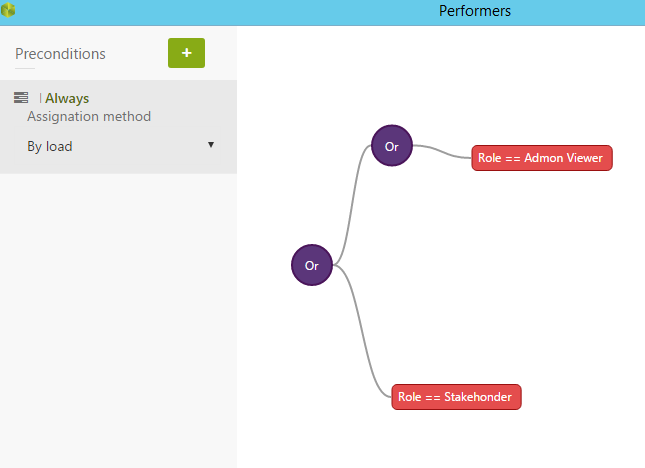
Бизнес-процесс «Технологическое требование» будет автоматизировать процесс начиная от подачи заявки клиента для реализации технологического требования под необходимые нужды и заканчивая выкладыванием решения в открытый доступ. В качестве технологического требования может быть: создание серверной инфраструктуры, разворачивание необходимых виртуальных машин, настройка коммутационного оборудования и другое.
«Технологическое требование» будет включать следующие этапы: инициализация заявки, производственные работы, верификация инициатором и выкладывание в открытый доступ.

Разработанная модель данных бизнес-процесса «Технологическое требование» представлена ниже
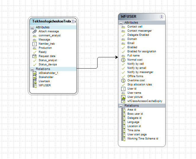
Атрибуты главной таблицы «Требование»
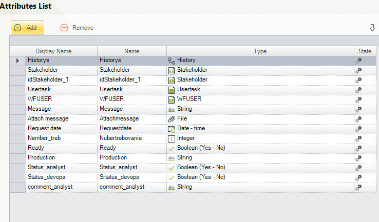
Таблица WSUSER является системной, из системной таблицы мы можем получить текущего пользователя, контактные данные и всю остальную информацию. Бизнес-процесса «Технологическое требование» имеет следующие визуальные формы
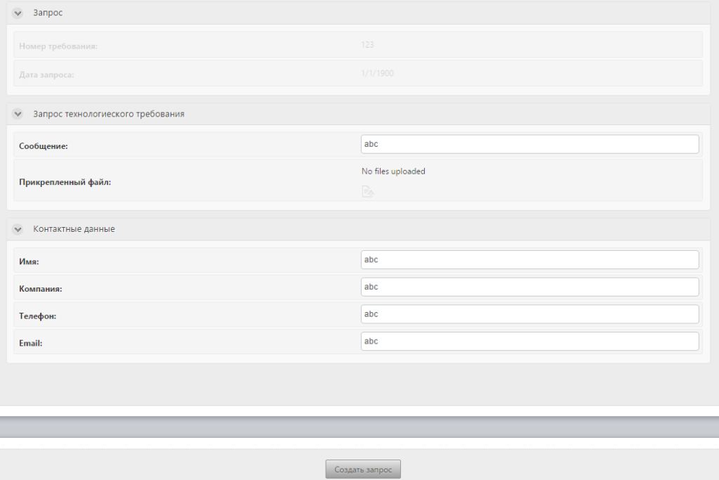
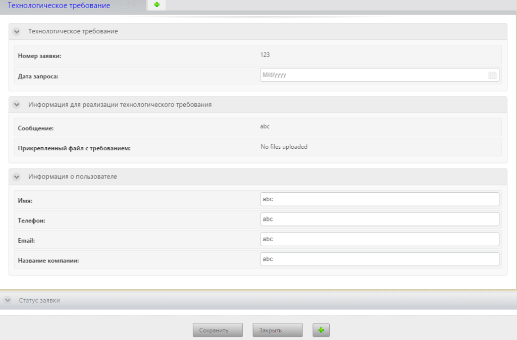
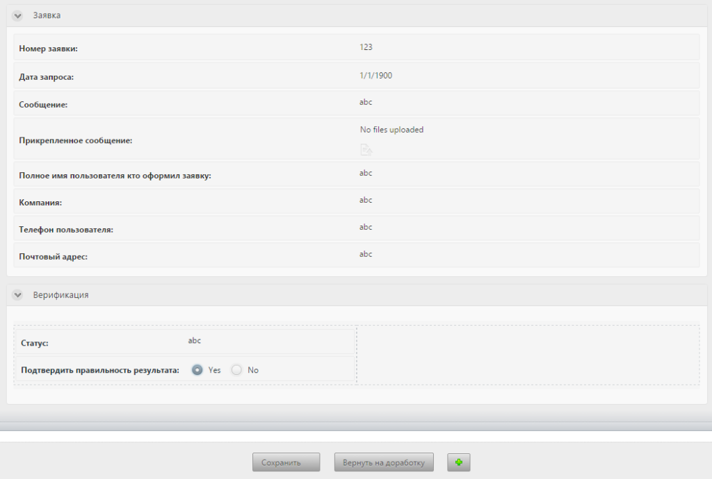
Для каждого условия «исключающие или» нам необходимо прописать правило, по которому будет проверяться условие для дальнейшего перехода к следующей функции.
Условия:
Tekhnologicheskoetrebova.ready is equal to true;
Tekhnologicheskoetrebova.ready is equal to false;
Tekhnologicheskoetrebova.status_analyst is equal to true;
Tekhnologicheskoetrebova. status_analyst is equal to false;
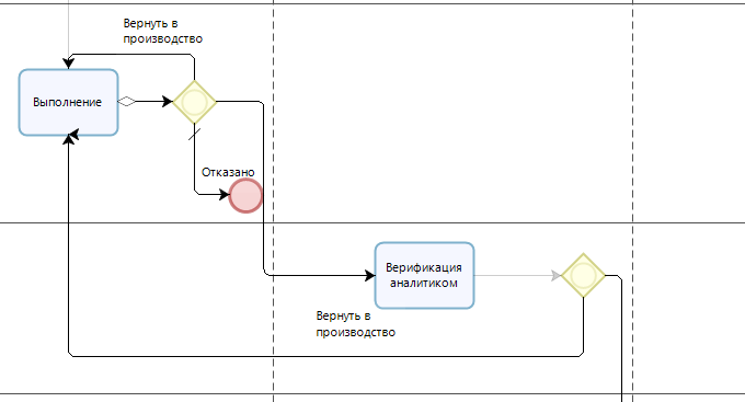
На этапе определения «Activity Action» (Events) на кнопку «Сохранить» в графическую форму процесса «Выполнение» добавляем следующие выражения:
Currenttask –в поле «номер заявки» будет подставляться системный номер заявки;
CurrentData – в поле «дата запроса» будет добавлять системная дата;
Выражение:
<TekhnologicheskoeTrebova.Nubertrebovanie> = Me.Case.CaseNumber;:
<TekhnologicheskoeTrebova.Requestdate> = DateTime.Now; После определения бизнес правил определяем исполнителей задач.
У нас будут существовать следующие роли: programmer (программист), stakeholder (внешнее лицо), devops (системный администратор), admon viewer (администратор), analyst (аналитик).
Мы можем определить 4 состояний задач для исполнения пользователями: по нагрузке, все, последовательны, первый доступный. Имеются условия and (и), or (или) и properties (свойства), благодаря котором мы можем масштабировать количество пользователей. Определяем условия для всех функций
Or Role==Stakeholder or Role == Admon Viewer;
Or Role==Manager or Role == Admon Viewer;
Or Role==Chief manager or Role == Admon Viewer;
Or Role==Programmer or Role == Admon Viewer;
Or Role==DevOps or Role == Admon Viewer;
Or Role==Analyst or Role == Admon Viewer;
Or Role==Tester or Role == Admon Viewer;
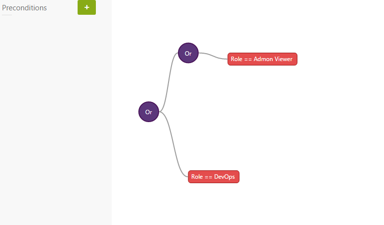
Для запуска бизнес-процессов в корпоративной сети необходимо развернуть серверную операционную систему Windows, настроить DNS сервер, установить IIS сервер, развернуть базу данных.
В качестве серверной операционной системы была выбрана Windows Server 2012 R2. В качестве сервера базы данных был выбран — SQL Server.
SQL Server является одной из наиболее популярных систем управления базами данных (СУБД) в мире. Данная СУБД подходит для самых различных проектов: от небольших приложений до больших высоконагруженных проектов. SQL Server характеризуется такими особенностями как: 1) производительность. SQL Server работает очень быстро; 2) надежность и безопасность. SQL Server предоставляет шифрование данных; 3) простота. С данной СУБД относительно легко работать и вести администрирование.
После установки СУБД устанавливаем оснастку IIS и проверяем работоспособность веб сервера.
Основным компонентом IIS является веб-сервер, который позволяет размещать в Интернете сайты. IIS поддерживает протоколы HTTP, HTTPS, FTP, POP3, SMTP, NNTP (т.е все основные протоколы). По данным компании Netcraft на июнь 2015 года, почти 22 млн сайтов обслуживаются веб-сервером IIS, что составляет 12,32 % от общего числа веб-сайтов, остальные веб-серверы используют Apache, Nginx. Производим экспорт базы данных (формат bak) на разрабатываемой машине и импортируем ее на сервер через MSSQL Server Management
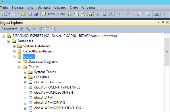
Проверяем работоспособность IIS и портала BPM Bizagi


Необходимо добавить организационные структуры, для разделения пользователей по ролям и отношению к организации
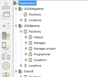
Проверка работоспособности бизнес-процессов


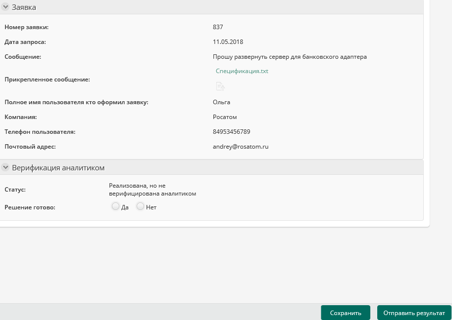
Экспортируем наши бизнес-процессы в статические веб страницы и создадим портал, где мы будем хранить всю документацию по бизнес-процессам, и где любой пользователь внутренней сети предприятия сможет посмотреть её

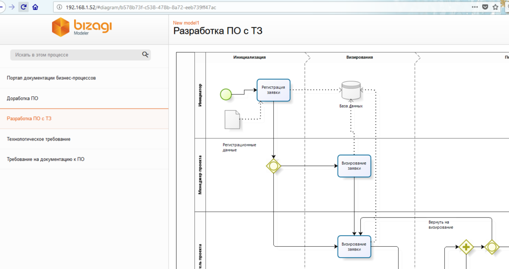
Метки: bizagiBizAgi Process Modeler