-
Contents
-
Table of Contents
-
Troubleshooting
-
Bookmarks
Quick Links
Rider’s Manual (US Model)
R 1200 RT
BMW Motorrad
Freude am Fahren
Related Manuals for BMW Motorrad R 1200 RT 2005
Summary of Contents for BMW Motorrad R 1200 RT 2005
-
Page 1
Rider’s Manual (US Model) R 1200 RT BMW Motorrad Freude am Fahren… -
Page 2
Motorcycle/Retailer Data Motorcycle data Retailer Data Model Contact in Service Vehicle identification number Ms./Mr. Color number Phone number First registration Retailer’s address/phone number Registration number (company stamp) -
Page 3
We wish you many miles of community of BMW riders. safe and enjoyable riding Familiarize yourself with your new motorcycle so that you BMW Motorrad. can ride it safely and confi- dently in all traffic situations. Please read this Rider’s Man- ual carefully before starting to use your new BMW motor- cycle. -
Page 4: Table Of Contents
Table of Contents 3 Status indicators ..21 Heated hand grips ..49 Multifunction display ..22 Seat heating ..49 You can also use the index at Clutch .
-
Page 5
7 Maintenance ..97 Paint care ….130 BMW Motorrad service General instructions ..98 Protective wax quality . -
Page 6
Confirmation of service ….156… -
Page 7: General Instructions
General instructions Overview……6 Abbreviations and symbols ..6 Equipment ….. . 7 Technical data .
-
Page 8: Overview
Optional equipment Overview Abbreviations and BMW equipment avail- symbols Chapter 2 of this Rider’s Man- able only as a factory ual will provide you with an Indicates warnings that installed option. initial overview of your motor- you must comply with for cycle.
-
Page 9: Equipment
on the basis of the data, illus- Equipment Technical data trations or descriptions in this When you ordered your BMW All dimensions, weights and manual. motorcycle, you chose vari- performance specifications ous items of custom equip- in the Rider’s Manual refer ment.
-
Page 11: Overviews
Overviews General view, left side ..11 General view, right side ..13 Underneath seat ….15 Left handlebar fitting .
-
Page 13: General View, Left Side
General view, left side Headlight adjustment (vertical) beneath instru- ment panel ( Brake-fluid reservoir 103) Radio operating unit (OE) Onboard socket ( Onboard socket (OE) Adjuster, rear shock ab- sorber ( Oil sight glass ( Filler neck, engine oil 100)
-
Page 15: General View, Right
General view, right side Seat lock ( Switch for passenger seat heating (OE) under passenger seat ( Mounting for tank ruck- sack (OA) Filler neck, fuel tank Front clutch fluid reser- voir Electrically adjustable windshield ( Storage or radio com- partment (…
-
Page 17: Underneath Seat
Underneath seat Height adjuster, front seat ( Battery ( 122) Brake-fluid reservoir, rear 104) Adjuster, spring preload, rear ( Toolkit ( Type plate Helmet holder ( Table of tire pressures Label, payload…
-
Page 18: Left Handlebar Fitting
Left handlebar fitting Switch for cruise control (OE) ( Radio operating unit (OE) ESA button (OE) ( Button for windshield ad- justment ( Horn button Button for left turn indi- cator and hazard warning flashers ( 55) ( Switch, high-beam head- light and headlight flash- er (…
-
Page 19: Handlebar Fitting, Right
Handlebar fitting, right Onboard computer but- ton (OE) ( Emergency ON/OFF switch ( Starter button with OE Heated handle- bar grips: Heated hand grips Button for right turn indi- cator and hazard warning flashers ( 55) ( Turn indicators off button Switch for driver’s seat heating (…
-
Page 20: Instrument Cluster
Instrument cluster Speedometer Warning and indicator lights ( Multifunction display Rev. counter Anti-theft alarm indicator light Setting for clock and display dimming ( Control, odometer ( Sensor for lighting of in- strument panel The instrument-cluster lighting has automatic day and night switchover.
-
Page 21: Headlight
Headlight High-beam headlight Low-beam headlight Side lights…
-
Page 23: Status Indicators
Status indicators Multifunction display … 22 Warning and indicator lights..23 ABS warning light … . . 23 Function indicators .
-
Page 24: Multifunction Display
Multifunction display Fuel gauge ( Area for radio display (see radio operating manual) Area for warning symbols Gear indicator ( Engine temperature indi- cator ( Tripmeter or area for dis- plays of onboard com- puter (OE) ( 41) ( Display area for clock, seat heating (OE), display dimming and ESA (OE) 42) (…
-
Page 25: Warning And Indicator
Engine temperature Warning and indicator ABS warning light lights The lateral bars under In some countries a different the temperature symbol display of the ABS warning show the engine temperature light is possible. level. Alternative display of General warning indi- ABS warning light.
-
Page 26
Overview of warning indicators Display Meaning lights up yellow The warning Electronic immobilizer is active EWS! indicated lights up yellow is indicated Fuel down to reserve ( lights up yellow is indicated Engine electronics ( lights up red is indicated Engine oil pressure insufficient lights up red is indicated… -
Page 27
Display Meaning is dis- Anti-theft alarm battery weak ( played with note lights up yellow is dis- Anti-theft alarm battery drained played with note… -
Page 28
Electronic immobilizer is A fuel shortage can lead The engine is running active to misfiring and to the in emergency operating engine dying unexpectedly. mode. Engine power may be General warning light Misfiring can damage the cat- reduced, and this can cause lights up yellow. -
Page 29
Engine oil pressure insuffi- Battery charge current in- If the warning on insufficient cient sufficient engine oil pressure appears General warning light despite a correct engine oil General warning light level: lights up red. lights up red. In addition to an insuf- Engine oil pressure sym- Battery charge current ficient engine oil level,… -
Page 30
gine can die suddenly and Replacing left low-beam Tail light or brake light bulb the battery can be exhaus- bulb ( 115) defective. tively discharged and there- Replacing right low-beam Replacing rear brake, tail fore destroyed. bulb ( 116) light or rear turn indicator Have the fault rectified as Replacing side light bulb bulbs (… -
Page 31: Abs Warning
Anti-theft alarm battery A combination of several bulb The anti-theft alarm battery weak defects is present. has no capacity. The opera- Battery symbol with note tion of the anti-theft alarm is See the fault descriptions no longer ensured with the above.
-
Page 32
Display 1. Display 2. The warning indicators in this chapter are described using display 1. -
Page 33
Overview of warning indicators Display Meaning lights up red Brake switch defective ( flashes 1x per Pull-away test not completed ( second flashes 4x per Self-diagnosis not completed ( second lights up red lights up ABS warning lights defective ( lights up red flashes 1x per ABS function not available (… -
Page 34
Brake switch defective Have the fault rectified as Do not use emergency soon as possible by a spe- braking if possible until the General warning light cialized workshop, prefer- starting-off test has been lights up red. ably an authorized BMW completed. -
Page 35
self-diagnosis has not been ior, and therefore accidents ABS warning light flash- completed. may result. es once per second. You can continue to ride. Brake early and avoid hard Without the ABS func- However, bear in mind that braking whenever possible, tion, the wheels may neither the ABS function as functions of the BMW Inte-… -
Page 36
Residual braking function the brake booster is avail- Checking front brake pad active able. thickness ( 101) Have the fault rectified as Checking brake pad thick- General warning light soon as possible by a spe- ness at rear ( 102) lights up red. -
Page 37
Switch off Ignition, then op- Have the fault rectified as ABS warning light flash- erate handbrake lever and soon as possible by a spe- es four times per sec- footbrake lever consecutive- cialized workshop, prefer- ond. ably an authorized BMW At least two faults have oc- motorcycle retailer. -
Page 39: Operation
Operation Headlight ….. 54 Turn indicators ….55 Ignition switch and steering lock .
-
Page 40: Ignition Switch And Steering Lock
Switching on ignition Switching off ignition Ignition switch and steering lock Keys You receive one master key and one spare key. If a key is lost, please note the informa- tion on the electronic immobi- lizer (EWS) ( 39). Ignition switch and steer- ing lock, tank filler cap Turn the key to position 1.
-
Page 41: Electronic Immobilizer Ews
The battery can be On level ground, always turn lizer can be started only with recharged via the onboard the handlebars to the left to the keys that belong to the socket. set the steering lock. vehicle. You can also have your authorized BMW motor- Turn the handlebars to the Locking handlebars…
-
Page 42: Hazard Warning Flashers
A spare key attached keys that belong to the mo- The hazard warning to the same ring as the torcycle. A key that has been flashers place a strain ignition key used to start the barred can subsequently be on the battery. Do not use engine could «irritate»…
-
Page 43: Odometer And Tripmeters
Switching off hazard Odometer and tripme- warning flashers ters Odometer Press tripmeter button 1 once briefly each time. Press turn-indicator cancel button 3. The odometer reading ap- Hazard warning flashers are pears in display field 1. switched off. Alternative: Press button for Selecting tripmeter left turn indicator 1 and right Switch on the ignition.
-
Page 44: Clock
Tripmeter and onboard The hour increments by one Clock each time you press the computer Setting clock button. On motorcycles with an on- Attempting to set the Press button 1 for longer board computer, the tripmeter clock while riding the than 2 seconds.
-
Page 45: Onboard Computer Oe
Adjusting dimming reached, brightness is reduced by one level. Onboard computer Selecting readings The following sequence is shown in the display field of Adjusting the dimming the onboard computer: while driving can lead to Residual range accidents. Average speed Only adjust the dimming when Average consumption the motorcycle is stationary.
-
Page 46
The determined residu- al range is an approxi- mate reading. BMW Motorrad Repeatedly press BC therefore recommends that button 1 until the average you do not try to use the full… -
Page 47: Ambient Temperature
Display shows «—.- mpg». Oil level is correct Ambient temperature The current ambient tempera- Oil level ture is displayed. Check oil level. An ice warning Oil level cannot be mea- appears if the ambient- sured (conditions as temperature reading drops stated above not satisfied).
-
Page 48: Cruise Control Oe
Setting road speed Step-by-step accelera- Cruise control tion Switching on cruise con- trol Briefly push button 3 in SET direction Briefly push button 3 in SET Cruise-control indicator direction Move switch 1 to ON. light lights up. Speed is increased by 1 Indicator light 2 in switch mph (2 km/h) each time lights up red.
-
Page 49
Stepless acceleration Step-by-step decelera- Stepless deceleration tion Briefly press button 3 in Briefly press button 3 in SET direction and hold. RES direction and hold. Briefly push button 3 in RES The motorcycle accelerates The motorcycle decelerates direction. steplessly. steplessly. Speed is decreased by ap- Release button 3. -
Page 50: Emergency On/Off Switch
Cruise control is deactivat- only to the cruising speed Emergency ON/OFF saved in memory, even switch though you might have Cruise-control indicator light intended slowing to a lower goes out. speed. Indicator light in switch re- mains on. Cruise-control indicator light lights up.
-
Page 51: Heated Hand Grips Oe
The engine can be easily and grips are switched off to en- Heated hand grips quickly switched off using the sure starting capability. emergency ON/OFF switch. Heated hand grips switch Heating function off. A Operating position. 50% heat output (one dot The handlebar grips can be B Engine switched off.
-
Page 52
switched off to ensure the Seat heating of passen- battery’s starting capability. ger seat Seat heating, front seat Heating function off. 50% heating power 100% heating power Switch for seat heating, rear seat Switch for seat heating, front seat The passenger seat can be heated at two levels. -
Page 53: Clutch
Shown in multifunction Driver’s seat 50% heat- ing capacity display Driver’s seat 100% heat- ing capacity Passenger seat 50% heating capacity Passenger seat 100% heating capacity Switch in middle posi- tion: Heating off. Clutch Switch pressed toward Switch on driver’s or pas- Adjusting clutch lever rear: 50% heating ca- senger heating.
-
Page 54: Brakes
bars or the handlebars in their Brakes mounts. Adjusting handbrake Attempting to adjust the lever clutch lever while riding The distance between han- the motorcycle can lead to dlebar grip and handbrake accidents. lever can be adjusted to any Adjust the clutch lever only of four positions.
-
Page 55
switched on longer than Switching on high-beam switch is pressed (headlight absolutely necessary. flasher). headlight Switching on side lights Switching on low-beam headlight Switch off the ignition. The low-beam headlight You can switch on the switches on automatically parking lights only imme- when you start the engine. -
Page 56: Headlight
Headlight range and Headlight range adjust- Headlight spring preload ment Adjusting headlight for The headlight range gener- RHD/LHD traffic ally remains constant due to When riding in countries the adjustment of the spring where traffic drives on the op- preload to the loading state. posite side of the road to that Spring preload adjustment in which the motorcycle was…
-
Page 57: Turn Indicators
A Position with heavy pay- Press left-hand turn indica- Press right-hand turn indi- load tor button 1. cator button 2. B Normal position After driving for approx. After driving for approx. ten seconds or after cov- ten seconds or after cov- Turn indicators ering a distance of approx.
-
Page 58: Storage Compartment
Switching off turn indica- Opening storage com- Closing storage com- tors partment partment Press turn-indicator cancel Turn lock barrel 1 perpen- Snap lid of compartment button 3. dicular to driving direction closed and push it down. with ignition key. Turn indicator switched off. The lock engages with an Lock of storage compart- audible click.
-
Page 59: Front And Rear Seats
Front and rear seats Removing passenger seat Make sure the ground is level and firm and park the motorcycle. When doing so, press the Pull the seat to the rear to rear seat down. release it from its holders. Lift the seat at the rear and Removing driver’s seat release the key.
-
Page 60
Adjusting driver’s seat Installing driver’s seat The front seat can be raised Installing passenger seat or lowered to either of two positions. Installing driver’s seat Adjusting driver’s seat If too much pressure is Make sure the ground is applied in the forward level and firm and park the direction, there is a danger motorcycle. -
Page 61
gage in the lower mount on with OE Seat heating: the frame. Slide front seat forward on- to seat supporting rod 1. Close connector 1. Check that the seat is cor- Firmly push the front seat rectly seated. into the mount. Installing passenger seat If too much pressure is applied in the forward… -
Page 62: Helmet Holder
Firmly press down on the Removing passenger seat Mirrors seat at the rear. Adjusting mirrors The seat engages with an audible click. Helmet holder Helmet holders under passenger seat Move the mirrors into the The helmet catch can desired position by pressing scratch the paneling.
-
Page 63: Windshield
Press button 1 at top. acteristic to suit the spring Windshield preload. Windshield is raised. Adjustable windshield Press button 1 at bottom. Adjusting the spring Windshield is lowered. preload while the motorcycle is being ridden Spring preload can lead to accidents. Adjust the spring preload only Adjusting spring preload when the motorcycle is sta-…
-
Page 64: Shock Absorbers
To decrease spring preload, Shock absorbers turn handwheel 1 in direc- Adjusting damping tion of arrow LOW. The damping must be adapt- ed to the spring preload. An increase in spring preload re- quires firmer damping, a re- duction in spring preload re- quires softer damping.
-
Page 65: Electronic Suspension
Adjust the rear shock ab- Turn adjusting screw in di- motorcycle to the load and sorber, using a screwdriver rection of arrow H up to the road surface. The damp- to turn adjusting screw 1. stop, then a three-quarter ing setting is displayed in the turn in direction of arrow S multifunction display in the area 1, and the spring preload…
-
Page 66
Display goes out again au- normal damping tomatically after a few sec- onds. sporty damping Adjusting damping If button 1 is not pressed Switch on the ignition. for a longer time, shock ab- sorbers are set as indicat- ed. During the setting pro- cedure, the display flashes. -
Page 67: Tires
Two-up (with luggage) pressure, use a metal valve Tire pressure for rear wheel cap with rubber sealing ring — passenger and luggage on the rear wheel and tighten 42.1 psi (with tire cold) If button 1 is not pressed it securely. In case of insufficient tire for longer than one second, pressure:…
-
Page 69: Riding
Riding Safety instructions … . . 68 Checklist ….. . 70 Starting .
-
Page 70: Safety Instructions
settings of the spring-strut Do not ride your motorcy- Safety instructions and shock absorber system cle after consuming alcohol, Rider’s equipment drugs and/or medication. imbalanced load Do not ride without the cor- loose clothing rect clothing. Always wear: Risk of poisoning insufficient tire pressure helmet Exhaust fumes contain car-…
-
Page 71: Catalytic Converter
tion system when the engine Risk of fire Tampering with the con- is running. trol unit of the electronic Temperatures at the exhaust are high. engine-management sys- Catalytic converter Flammable materials If misfiring causes unburned (e.g. hay, leaves, grass, Tampering with con- fuel to enter the catalytic con- clothing and luggage, etc.) trol unit of electronic…
-
Page 72: Checklist
engine-management Starting engine Starting system. Side stand You cannot start the Checklist motorcycle with the side Use the following checklist stand extended and a gear to check important functions, engaged. The engine will settings and wear limits be- switch itself off if you start fore you ride off.
-
Page 73
self-diagnosis has been At ambient temperatures be- a «Pre-ride check», is indicat- performed. low 32 °F (0 °C), actuate the ed by the lettering CHECK! clutch after switching on the in the display. With the OE Emergency ON/OFF ignition. cruise control, the light switch 1 in operating is also displayed. -
Page 74: Starting Off
If the general warning Phase 1 The ABS warning light light cannot be dis- does not go out until af- Self-diagnosis is performed. played, several malfunctions ter completion of the starting- General warning light cannot be indicated. off test. lights up red. Watch the display of the gen- ABS warning light flash- Starting off…
-
Page 75: Running In
The ABS warning light goes Exceeding the specified exerting greater pressure on out after completion of the engine speeds while run- the levers. starting-off test. ning in will lead to increased New brake pads can ex- engine wear. If an error message is shown tend stopping distance after the starting-off test is Adhere to the specified en-…
-
Page 77: Parking Your Motorcycle
Slowly lean the motorcycle On a grade, the motor- Parking your motorcy- to the side until its weight cycle should always face is taken by the stand and uphill; select 1st gear. Placing on side stand dismount to the left. When you prop the If the ground is soft or motorcycle on the…
-
Page 79
An extended side stand Remove from side can catch on the ground stand when the motorcycle is mov- ing and lead to a fall. Brake servo assistance Retract the side stand before is not available when the moving the vehicle. ignition is off;… -
Page 81
Excessive movements Placing on center could result in the cen- stand ter stand retracting, and the motorcycle would topple as a If the ground is soft or result. uneven, there is no guar- Do not sit on the motorcycle antee that the motorcycle will while it is resting on the cen- rest firmly on the stand. -
Page 83
Pushing off center stand Brake servo assistance is not available when the ignition is off; the motorcycle can start to roll. Especially on inclines, switch on the ignition and wait for the ABS self-diagnosis. Switch on the ignition. Wait for ABS self-diagnosis to complete. -
Page 84: Refueling
Make sure the ground is Premium grade unleaded Refueling level and firm and park the fuel Fuel is highly flammable. motorcycle. 98 ROZ Fire at the fuel tank can Fuel types can be used with result in fire and explosion. poorer performance and Do not smoke.
-
Page 85: General Brake System
Salt on brakes Dirt or mud on brakes General brake system The full braking effect When the motorcycle Descending mountain can be delayed if the is ridden on loose sur- passes motorcycle is ridden on salt- faces or muddy roads, the There is a danger of the covered roads and the brakes brakes may fail to take effect…
-
Page 86: Brake System With Bmw Integral Abs
minimize braking distances Partially integral brake Brake system with noticeably, even when road BMW Integral ABS Your motorcycle is equipped conditions are poor. When with a partially integral brake Sensitive electronic con- driving straight ahead, BMW configuration. Both front and trol Integral ABS enables safe, re- rear brakes are applied simul-…
-
Page 87
higher braking efficiency than Bear in mind that ABS can- the ABS function is unavail- standard brake systems. not be relied on in all circum- able in the brake system in stances to prevent the rear question. When the residu- ABS anti-lock braking wheel from lifting clear of the al braking function is active,… -
Page 88
As the residual braking function means that the lever path before the brake pressure is built up can be longer, BMW Motorrad rec- ommends that a larger lever path be set at the handbrake lever. In the case of residual… -
Page 89: Accessories
Accessories General instructions … 88 Onboard socket ….88 Luggage ….. . 91 Case .
-
Page 90: General Instructions
BMW cannot evaluate General instructions Onboard socket whether every product of BMW Motorrad recommends Ratings other manufacturers is suit- the use of parts and acces- The supply to the socket is able for use on BMW motor- sories for your motorcycle…
-
Page 91
Cable routing The cables from the onboard socket to the auxiliary device must be routed in such a way that they: do not impede the rider do not restrict or obstruct the steering angle and han- dling characteristics Onboard socket, rear left cannot be trapped Operating electrical ac- Improperly routed cables… -
Page 93: Luggage
Make sure that the weight Luggage is uniformly distributed be- Correct loading tween right and left. Pack heavy items at bottom Overloading and uneven and toward inboard side. loading can diminish the Max. load in each case (left riding stability of the motorcy- and right): 22 lbs (10 kg).
-
Page 94: Case
Closing case Case Opening case Press lock barrel 1. Unlocking lever 2 pops up. Pull lever 2 back as far as it Fold lever 2 toward rear. will go. Turn key in case lock per- Open case lid. Close case lid 3 and press pendicular to direction of down.
-
Page 95
Removing case Push lever down. Turn the key clockwise (left case) or counterclockwise The lever engages. Turn key in case lock per- (right case). Turn key in case lock paral- pendicular to direction of Handle 4 pops out. lel to direction of travel. travel. -
Page 96: Topcase Oa
The case is released and Topcase can be removed. Opening Topcase Mounting case Unlatch the handle and pull it up as far as it will go. Push the handle of the case down until it engages (the colored indicator on the Position lock barrel vertically handle must disappear).
-
Page 97
Closing Topcase Removing Topcase Lift the Topcase at the rear and pull it off the carrier. Fully open locking lever 8. Position lock barrel horizon- Unlock lid and press down. tally in Topcase. Mounting Topcase Check that nothing is Topcase is locked. Position lock barrel horizon- trapped between the lid and Turn the key clockwise. -
Page 98
dicator on the handle must disappear). Topcase is locked. Turn the key clockwise. Hook the Topcase into position on the carrier. Handle 6 pops out. Make sure that hooks 7 are securely seated in corresponding mounts 8. Pull handle 6 up as far as it will go. -
Page 99: Maintenance
Maintenance Lamps ….. . . 113 Jump starting ….121 General instructions .
-
Page 100: General Instructions
General instructions Toolkit Overview of toolkit The ‘Maintenance’ chapter Removing toolkit describes work involving the Make sure the ground is checking and replacement of level and firm and park the wear parts that can be per- motorcycle. formed with a minimum of ef- Removing passenger seat fort.
-
Page 101: Overview Of Supplemental
can only be checked at the oil Overview of supple- Engine oil sight glass. mental set Checking engine oil level Make sure ground is level The engine can seize if and firm and place motorcy- the oil level is low, and cle at operating temperature this can lead to accidents.
-
Page 102: General Brake System
Topping up engine oil General brake system Functioning brakes A properly functioning brake system is a basic require- ment for the road safety of your motorcycle. Do not ride the motorcycle if you have any doubts about the dependability of the brake Specified level of engine oil system.
-
Page 103: Brake Pads
Checking brake opera- preferably an authorized BMW motorcycle retailer. tion Switch on the ignition. Brake pads Wait for ABS self-diagnosis Checking front brake pad to complete. Pull the handbrake lever. thickness The pressure point must be Continuing to use brake clearly perceptible.
-
Page 104
The wear markings must be Make sure the ground is clearly visible on the brake level and firm and park the pads must. motorcycle. If the wear indicating marks are no longer clearly visible: Have the brake pads re- placed by a specialized workshop, preferably an au- thorized BMW motorcycle The brake disk must not be… -
Page 105: Brake Fluid
preferably an authorized Residual brake pad thick- Brake fluid BMW motorcycle retailer. ness Checking front brake flu- at least 75% (3 rings visible) id level at least 50% (2 rings visible) A low fluid level in the 50-25% (1 ring visible) brake reservoir can al- Replace brake pad (No low air to penetrate the brake…
-
Page 106
system. This significantly re- duces braking efficiency. Brake early. Have the fault remedied as quickly as possible by a certified workshop, preferably an authorized BMW motorcycle retailer. Checking rear brake fluid Read off the brake fluid level Read off the brake fluid level level at the reservoir 1. -
Page 107: Clutch
Brake fluid DOT4 Tires have wear indica- If no clear pressure point can tors integrated into the The brake fluid level must be felt: main tread grooves. If the tire not drop. Have the clutch checked tread has worn down to the by a specialized workshop, If the brake fluid level drops level of the marks, the tire is…
-
Page 108: Wheels
If a risk of the brake pads be- BMW Motorrad has not ap- ing pressed together to the proved the wheels and tires, it extent that they cannot be…
-
Page 109
Installing front wheel Carefully pull brake calipers BMW Motorrad offers an Threaded fasteners not back and out until clear of adapter piece for remov- tightened to the speci- brake disks. -
Page 110
ably an authorized BMW mo- torcycle retailer. During the following work, parts of the front brake, in particular of the BMW Integral ABS, can be damaged. Take care not to damage the brake system, in particular the ABS sensor with cable and Roll the front wheel into the Install quick-release axle 6 the ABS sensor ring. -
Page 111
Install mounting screws 2 Install screws 1 on left and The cable of the ABS with torque. right. sensor could chafe Brake caliper on slider tube Switch on the ignition. through if it comes into contact with the brake disk. 22 lb/ft Wait for self-diagnosis to complete. -
Page 112
Make sure ground is level and firm and park motorcy- cle on its center stand. Remove screw 2 for bracket Remove screws 3 from rear of end muffler from passen- wheel while supporting ger footrest. wheel. Roll the rear wheel out to- Unscrew clamping screw 1 ward the rear. -
Page 113
Insert rear wheel in hole for wheel and the end muffler wheel centering device. must be at least 0,79 in. Install screw 2 for bracket of end muffler on rear footrest, but do not tighten it. Turn the end silencer to its initial position. -
Page 114: Front Wheel Stand
14 lb/ft the front wheel stand to the stand before lifting it with the desired height. BMW Motorrad front wheel Front wheel stand Center the front wheel stand stand. relative to the front wheel Front wheel stand…
-
Page 115: Lamps
Lamps General instructions A bulb failure is signaled to you in the multifunction dis- play by a warning indicator. If the brake or rear light fails, the general warning light al- so lights up in yellow. If the rear light fails, the brake light Align two mounts 2 so that If the motorcycle is rest- is used as a substitute in that…
-
Page 116
The bulb is pressurized topple in the course of the and can cause injury if operations described below. damaged. Make sure that the motorcy- Wear eye and hand protection cle is steady on its stand. when replacing bulbs. Make sure the ground is An overview of the bulb level and firm and park the types installed in your… -
Page 117
Check that the bulb is cor- rected seated (by looking in through the headlight lens). Replacing left low-beam bulb If it is not standing firm- ly, the motorcycle could topple in the course of the operations described below. Remove bulb 4. Turn cover 1 counterclock- Make sure that the motorcy- wise and remove it. -
Page 118
Install bulbs in reverse or- Make sure that the motorcy- der. cle is steady on its stand. Make sure the ground is level and firm and park the motorcycle. Switch off the ignition. To achieve better acces- sibility, turn the handle- bars to the left. -
Page 119
Check that the bulb is cor- rected seated (by looking in through the headlight lens). Left and right side-light bulb The procedure for replacing the left side-light bulb is de- scribed below. The proce- dure for replacing the right Disconnect plug 2. Remove bulb 4. -
Page 120
Apply firm forward pressure Remove screw 1 while Side-light bulb is accessible with the flat of your hand to holding fairing side panel in through opening. push the mirror back out of place. the anchorage. Remove bulb holder 3 from Take off fairing side panel 2. -
Page 121
of motorcycle: swivel lever upward). When installing fairing pan- If rubber mounts or re- el 2, make sure that lug of taining pins of the mir- panel is correctly seated in rors are greased, the mirrors Pull bulb 5 out of bulb hold- corresponding recess. -
Page 122
Replacing rear brake, tail Press the bulb into its sock- et and turn it counterclock- light or rear turn indica- wise to remove. tor bulbs Install new bulb in reverse If it is not standing firm- order. ly, the motorcycle could topple in the course of the Replacing front turn indi- operations described below. -
Page 123: Jump Starting
Press bulb 2 into its socket ly in their corresponding and turn it counterclockwise mounts. to remove. Jump starting Install new bulb in reverse order. Jump starting The wires leading to the onboard socket do not have a load-capacity rating adequate for jump-starting Apply firm forward pressure the engine.
-
Page 124: Battery
A short-circuit can result battery from the onboard protect starter and donor if the crocodile clips of electrical system. battery. the jump leads are acciden- Remove the protective cap Allow both engines to idle tally brought into contact with from the positive battery ter- for a few minutes before the motorcycle.
-
Page 125
BMW Motorrad has de- Charging the battery via Keep the surface of the bat- veloped a trickle-charger the onboard socket is… -
Page 126
Always charge a completely Charging disconnected Removing passenger seat drained battery directly at the battery terminals of the disconnected Removing driver’s seat Charge the battery using a battery. suitable charger. Switch off the ignition. Charge the disconnect- Comply with the operating ed battery via the onboard instructions of the charger. -
Page 127
Then pull off protective cap Then install negative cable 2 and remove battery positive and hand-tighten screw. cable 3. Switch on the ignition. Lift out battery upward; if it Without starting engine, is difficult to move, moving it hold throttle twistgrip in ful- back and forth will help. -
Page 129: Care
Care Care products ….128 Washing your motorcycle ..128 Cleaning sensitive motorcycle parts ……129 Paint care .
-
Page 130: Care Products
Care products Washing your motor- brakes might not take effect cycle BMW Motorrad recommends immediately. that you use the cleaning BMW Motorrad recommends Brake early until the brakes and care products you can that you use BMW insect re- are dry or braked until dry.
-
Page 131: Cleaning Sensitive Motorcycle Parts
Soften stubborn dirt and Radiator Cleaning sensitive mo- dead insects by covering torcycle parts Clean the radiator regular- the affected areas with a wet ly to prevent overheating of Plastics cloth. the engine due to inadequate Clean plastic parts with water cooling.
-
Page 132: Paint Care
For the protective wax coat- sponding auxiliary stands. However, remove particularly ing of paint, BMW Motorrad Before storing the aggressive materials imme- recommends using only BMW vehicle, have the engine diately; otherwise changes in…
-
Page 133: Returning Motorcycle To
Returning motorcycle to use Remove protective wax coating. Clean motorcycle. Install a charged battery. Before starting: Observe checklist.
-
Page 135: Technical Data
Technical data Troubleshooting chart ..134 Threaded fasteners … 135 Engine ….. . . 136 Riding specifications .
-
Page 136: Chart
Troubleshooting chart Engine does not start at all or is very difficult to start Possible cause Remedy Emergency ON/OFF switch activated. Emergency ON/OFF switch in operating posi- tion. Side stand extended and gear engaged. Retract side stand ( 70). Gear engaged and clutch not operated. Place transmission in neutral or disengage clutch( 70).
-
Page 137: Threaded Fasteners
Threaded fasteners Activity Type of threaded fastener Tightening torques Front wheel Clamping screw for quick-release M8 x 35 14 lb/ft axle Quick-release axle in axle mount M24 x 1.5 37 lb/ft Brake caliper on slider tube M8 x 32 — 10.9 22 lb/ft Rear wheel Rear wheel on wheel carrier…
-
Page 138: Engine
Engine Engine design longitudinally mounted twelve-cylinder, four- cycle opposed-twin engine with one overhead cam each, air cooling, oil-cooled exhaust sys- tem and electronic fuel injection Effective displacement 1170 cc Cylinder bore 4 in Piston stroke 2.9 in Compression ratio 12.0:1 Rated output 110 hp, — at engine speed: 7500 min with OE Power reduction:…
-
Page 139
Oil grades Engine oils of the API classification SF or bet- ter. Engine oils of the ACEA classification A2 or better. BMW Motorrad recommends not using synthetic oils for the first 6,000 miles (10,000 km). Ask your BMW motorcycle retail-… -
Page 140: Riding Specifications
Permissible viscosity classes SAE 5 W-30 -4…68 °F, Operation at low temperatures SAE 10 W-40 14…86 °F, Operation at moderate tempera- tures SAE 15 W-40 or SAE 20 W-40 >32 °F, Operation at high temperatures SAE 5 W-50 or SAE 10 W-50 >-4 °F, Use high-quality and synthetic oils.
-
Page 141: Clutch
Clutch Clutch design single dry plate with high-leverage pressure plate Transmission Transmission design fully helical 6-speed transmission with inte- grated torsional vibration damper, claw shift- ing via sliding sleeves Gear ratios Transmission primary gear ratio 1.824 (31:17 teeth) Gear ratio in 1st gear 2.277 (41:18 teeth) Gear ratio in 2nd gear 1.583 (38:24 teeth)
-
Page 142: Rear-Wheel Drive
Rear-wheel drive Rear-wheel drive design shaft drive with bevel gears Gear ratio of rear-wheel drive 2.62:1 Running gear Front-suspension design BMW Telelever, tilt decoupled, leading link centrally mounted in main frame/on engine, with externally seated suspension strut Total suspension travel of front suspension 4.7 in, on wheel Rear suspension strut design Central spring strut with single-tube gas-filled…
-
Page 143: Brakes
Brakes Front brake design Hydraulic two-disk brake with 4-piston fixed calipers and floating brake disks Front brake pad Sintered metal Front brake pads — wear marking The wear markings must be clearly visible on the brake pads must. Rear brake design Hydraulic disk brake with 2-piston floating caliper and fixed brake disk Rear brake pad…
-
Page 144: Wheels And Tires
Wheels and tires Front wheel design Cast wheel with 5 double spokes, MT H2 Front-wheel rim size 3.50″ x 17″ Front-wheel tire designation 120/70 ZR 17 Rear wheel design Cast wheel with 5 double spokes, MT H2 Rear-wheel rim size 5.50″…
-
Page 145: Electrical System
Electrical system Current limit values for onboard sockets 10 A Fuses All circuits are electronically protected, so plug-in fuses are no longer necessary. If an electronic fuse trips and de-energizes a cir- cuit, the circuit is active as soon as the ig- nition is switched on after the fault has been rectified.
-
Page 146
Bulbs High-beam headlight bulb — standard designa- Halogen bulb H7 tion High-beam headlight bulb — voltage 12 V High-beam headlight bulb — wattage 55 W Low-beam headlight bulb- standard designa- Halogen bulb H7 tion Low-beam headlight bulb — voltage 12 V Low-beam headlight bulb — wattage 55 W Side-light bulb standard designation… -
Page 147: Frame
Frame Frame design Steel-tube front frame with steel-tube rear frame and carrying drive unit Location of type plate Rear frame lug on right under passenger seat Location of vehicle identification number (VIN) Front frame, upper center Dimensions Overall length 87.8 in Maximum height 56.3 in, in DIN normal-load position;…
-
Page 148: Weights
Weights Unladen weight 571 lbs, DIN unladen weight, ready for road, 90% full tank of gas, without OE Permitted total weight 1091 lbs Max. payload 520 lbs…
-
Page 149: Service
Service BMW Motorrad service ..148 BMW Motorrad service quality ….. . . 148…
-
Page 150: Service
By dance with BMW specifica- BMW Motorrad stands not having the necessary repairs tions. only for good handling and a done properly and in good You can contact your BMW…
-
Page 151: Bmw Motorrad Service Card — On-The-Spot Breakdown
BMW Motorrad service certain time, others depend network With all new BMW motorcy- on the distance covered by cles, the BMW Motorrad Ser- With its worldwide service the motorcycle. vice Card protects you in the network BMW Motorrad sup- event of a breakdown with…
-
Page 152: Schedules
BMW Service Maintenance sched- ules After the first 6,000 miles (10,000 km) and every The maintenance schedule for additional 12,000 miles your motorcycle depends on (20,000 km) (18,000 miles, the equipment installed, and 30,000 miles, 40,000 miles on the motorcycle’s age and etc.
-
Page 153: Confirmation Of Maintenance Work
Confirmation of maintenance work BMW Pre-delivery BMW Running-in Check Check Carried out properly in Carried out properly in accordance with work- accordance with work- shop specifications. shop specifications. at miles: Brake fluid changed Without BMW Inte- gral ABS With BMW Integral Wheel circuit Control circuit Date, stamp, signature…
-
Page 154
BMW Service BMW Service BMW Service BMW Annual In- BMW Annual In- BMW Annual In- spection spection spection BMW Service BMW Service BMW Service BMW Inspection BMW Inspection BMW Inspection Carried out properly in Carried out properly in Carried out properly in accordance with work- accordance with work- accordance with work-… -
Page 155
BMW Service BMW Service BMW Service BMW Annual In- BMW Annual In- BMW Annual In- spection spection spection BMW Service BMW Service BMW Service BMW Inspection BMW Inspection BMW Inspection Carried out properly in Carried out properly in Carried out properly in accordance with work- accordance with work- accordance with work-… -
Page 156
BMW Service BMW Service BMW Service BMW Annual In- BMW Annual In- BMW Annual In- spection spection spection BMW Service BMW Service BMW Service BMW Inspection BMW Inspection BMW Inspection Carried out properly in Carried out properly in Carried out properly in accordance with work- accordance with work- accordance with work-… -
Page 157
BMW Service BMW Service BMW Service BMW Annual In- BMW Annual In- BMW Annual In- spection spection spection BMW Service BMW Service BMW Service BMW Inspection BMW Inspection BMW Inspection Carried out properly in Carried out properly in Carried out properly in accordance with work- accordance with work- accordance with work-… -
Page 158: Confirmation Of Service
Confirmation of service The table is intended as proof of maintenance, warranty and repair work, the installed optional accessories and any special campaign (recall) work carried out. Work carried out at miles: Date…
-
Page 159
Work carried out at miles: Date… -
Page 160
Brake lever Clock Abbreviations and symbols, 6 adjusting handbrake adjusting, 18 lever, 52 setting, 42 warning light, 23 Brake pads Clutch Accessories check front, 101 adjusting clutch lever, 51 general instructions, 88 check rear, 102 checking operation, 105 Anti-theft alarm, 18 running in, 73 fluid reservoir, 13 Brakes, 101… -
Page 161
Hazard warning flashers, 16, Electrical system functional description, 39 technical data, 143 switching off, 41 warning indicator, 26 Emergency ON/OFF switching on, 40 switch, 17, 48 Headlight Frame Engine adjusting for RHD/LHD technical data, 145 engine-electronics warning traffic, 54 Front wheel stand, 112 indicator, 26 adjusting headlight Fuel… -
Page 162
Immobilizer replacing rear turn indicator Motorcycle functional description, 39 bulb, 120 general view of left side, 11 warning indicator, 26 replacing right low-beam general view of right bulb, 116 Indicator lights, 18 side, 13 overview, 23 replacing side light returning to use, 131 bulb, 117 Instrument cluster storing, 130… -
Page 163
electrical system, 143 Passenger seat Safety instructions, 68 engine, 136 heating, 13, 50 brakes, 83 engine oil, 137 Service, 148 installing, 59 frame, 145 Service Card, 149 removing, 57 fuel, 4, 137 Side stand Pre-ride check, 71 rear-wheel drive, 140 during starting, 70 running gear, 140 placing on side stand, 75… -
Page 164
Topcase Wheels installing front wheel, 107 closing, 95 installing rear wheel, 110 mounting, 95 removing front wheel, 106 opening, 94 removing rear wheel, 109 removing, 95 technical data, 142 Torques, 135 Windshield Transmission adjusting, 13, 16, 61 during starting, 70 technical data, 139 Troubleshooting chart, 134 Turn indicators… -
Page 165
The right to modify designs, equipment and accessories is reserved. Errors and omissions except- © 2005 BMW Motorrad Not to be reproduced either wholly or in part without writ- ten permission from BMW Motorrad, After Sales. -
Page 166
Tire pressure for front wheel — passenger and luggage 36.3 psi, with tire cold Tire pressure for rear wheel — passenger and luggage 42.1 psi, with tire cold BMW Motorrad Order No.: 01 47 7 698 857 BMW recommends 08.2005 2. -
Page 167
However, NHTSA cannot become involved in BMW Motorrad Order No: 01 47 7 706 697 08.2006… -
Page 168
Information on BMW Motorrad Integral ABS How does ABS work? resulting in a danger of falling. ensure driving stability when The maximum braking force Before this situation occurs, contact with the road surface which can be transferred to the ABS intervenes and is restored. -
Page 169
BMW Motorrad and extremely quickly, in com- accessories connected to retailer should be connected bination with a decreasing… -
Page 170
This optimally utilizes the rider to brake the motor- A fault in the BMW Motorrad the dynamic load increase on cycle. Integral ABS is indicated by a the front wheel. At the same… -
Page 171
• Always brake with the front How important is regular How is the BMW Motorrad maintenance? Integral ABS designed? and rear brakes Any technical system is The BMW Motorrad Integral • In clear situations, carry out always only as good as…
Не можете найти ответ на свой вопрос в руководстве? Вы можете найти ответ на свой вопрос ниже, в разделе часто задаваемых вопросов о BMW R 1200 RT (2005).
Как перевести мили в километры?
В чем разница между топливом E10 и E5?
Какова рекомендуемая частота замены масляного фильтра в двигателе BMW?
Как часто следует менять масло в двигателе BMW?
Как удалить ржавчину с устройства BMW мотоцикл?
Инструкция BMW R 1200 RT (2005) доступно в русский?
Не нашли свой вопрос? Задайте свой вопрос здесь
|
Detail Specifications: 807/807601-r_1200_rt_2005.pdf file (13 Dec 2022) |
Accompanying Data:
BMW Motorrad R 1200 RT 2005 Motorcycle PDF Руководство пользователя (Updated: Tuesday 13th of December 2022 01:30:10 PM)
Rating: 4.7 (rated by 37 users)
Compatible devices: S 1000RR 2014, R 1150 RT, F 800 R 2003, R 1200 RT 2013, R 18, G 310 GS, F 850 GS Adventure 2019, F 800 GS 2013.
Recommended Documentation:
Text Version of Руководство пользователя
(Ocr-Read Summary of Contents, UPD: 13 December 2022)
-
42, A spare key attached to the same ring as the ignition key used to start the engine could «irritate» the electronics, in which case the enabling signal for starting is not issued. The warning EWS is shown in the multifunction display. Always store the spare key separately from the ignition key. Replacement and extra keys You can obtain replacement keys…
-
153, Confirmation of maintenance work BMW Pre-delivery Check Carried out properly in accordance with work- shop specifications. Date, stamp, signature BMW Running-in Check Carried out properly in accordance with work- shop specifications. at miles: Brake fluid changed Without BMW Inte- gral ABS With BMW Integral ABS Wheel circuit Control circuit Date, stamp, signature 10 151 z Service
… -
46, BMW Motorrad R 1200 RT 2005 If the motorcycle is resting on its side stand, the level in the tank cannot be measured correctly, so this estimate of residual operating range will be inaccurate. When refueling, an increase in the fuel level is not registered by the onboard computer until the added quantity is more than a gallon. The determined residu- al range is an approxi- mate reading. BMW Motorrad therefore recommen…
-
113, BMW Motorrad R 1200 RT 2005 Insert rear wheel in hole for wheel centering device. Screw in screws 3 hand- tight and tighten diagonally with torque. Rear wheel on wheel carrier Tightening sequence: diag- onally 44 lb/ft Turn the end silencer to its initial position. If the gap between the rear wheel and the end muffler is too small, the rear wheel can overheat. The gap between the rear wheel and the end muffler mus…
-
72, engine-management system. Checklist Use the following checklist to check important functions, settings and wear limits be- fore you ride off. Brakes Front and rear brake fluid levels Clutch Clutch fluid level Shock absorber setting and spring preload Tread depth and tire pres- sure Firm seating of cases and luggage At regular intervals: Engine oil level (every time …
-
69, Riding Safety instructions …………. 68 Checklist . . ……………….. 70 Starting . . . ……………….. 70 Starting off ……………….. 72 Running in ……………….. 73 Parking your motorcycle . . . …. 75 Refueling . ……………….. 82 General brake system ……… 83 Brake system with BMW Integral ABS …………………….. 84 5 67 z Riding
… -
103, Checking brake opera- tion Switch on the ignition. Wait for ABS self-diagnosis to complete. Pull the handbrake lever. The pressure point must be clearly perceptible. The noise of the hydraulic pump of the BMW Integral ABS must be clearly audi- ble. Press the footbrake lever. The pressure point must be clearly perceptible. The noise of the hydraulic pump of the BMW…
-
164, BMW Motorrad R 1200 RT 2005 Topcase closing, 95 mounting, 95 opening, 94 removing, 95 Torques, 135 Transmission during starting, 70 technical data, 139 Troubleshooting chart, 134 Turn indicators indicator lights, 23 left, 16, 55 right, 17, 55 switching off, 17, 56 Type plate, 15 W Warning indicators display, 23 Warning lights, 18 overview, 23 warning light, general, 23 Weights technical data, 146 Wheels installing…
-
112, Make sure ground is level and firm and park motorcy- cle on its center stand. Unscrew clamping screw 1 on muffler. Do not remove sealing grease from clamp. Remove screw 2 for bracket of end muffler from passen- ger footrest. Turn the end silencer out. Engage first gear. Remove screws 3 from rear wheel while supporting wheel. Roll the rear wheel out to- ward the rear. Installing rear whe…
-
75, The ABS warning light goes out after completion of the starting-off test. If an error message is shown after the starting-off test is completed: Read the meaning of this display in the chapter «Dis- plays». Running in The first 600 miles (1 000 km) While running in the mo- torcycle, vary the throttle opening and engine-speed range frequently. Try to do most of your…
-
105, preferably an authorized BMW motorcycle retailer. Check brake pad at wear indicator 2. Rear brake-pad wear indi- cator Residual brake pad thick- ness at least 75% (3 rings visible) at least 50% (2 rings visible) 50-25% (1 ring visible) Replace brake pad (No rings visible) If brake pad thickness is not sufficient: Continuing to use brake pads beyond the mini- mum pad thick…
Recommended Instructions:
2015 — 740-776 MHZ ADDITIONAL INFORMATION, ZUG 78, 82413, TC-KB920S, G0588, MAS3132E


-
5MV-28199-30OWNER’S SERVICE MANUALMANUEL D’ATELIER DU PROPRIETAIREFAHRER-UND WARTUNGS-HANDBUCHMANUALE DI SERVIZIO DELPROPRIETARIOA4 HYOSHI MASTER H8 JUNE EDIT. DIV.Y 0YZ125(N)/LCYZ125(N)/LC5MV -9-30 HYOUSHI (QX3.3J) 00.10.12 18:06 y[W 1 (2,1) …
YZ125(N)/LC 558
-
MOTO GUZZI DESEA AGRADECERLEpor haber elegido uno de sus productos. Hemos preparado este manual para permitirle apreciar todas sus cualidades. Le aconsejamos que lea todosu contenido antes de conducir por primera vez. Contiene información, consejos y advertencias para el uso de su vehículo; asimismo, descubrirácaracterísticas, detalles y soluciones que lo con …
Breva 850 169
-
This manual should be considered a permanent part of the motorcycle and should remainwith the motorcycle when it is resold.This publication includes the latest production information available before printing. HondaMotor Co., Ltd. reserves the right to make changes at any time without notice and withoutincurring any obligation.No part of this publication may be reproduced without written permissi …
CBR600RR 2007 259
-
SWM Motorcycles srl declina qualsiasi responsabilità per eventuali errori in cui può essere incorsa nella compilazione del presente manuale e si riserva il diritto di apportare qualsiasi modifica richiesta dallo sviluppo evolutivo dei propri prodotti. Le illustrazioni riportate sono indicative e potrebbero non corrispondere esat- tamente al particolare trattato. É …
SM 125 R 2020 162
Popular Right Now:
Operating Impressions, Questions and Answers:
![]()
BMW Motorrad

Welcome to BMW
We congratulate you on your choice of a motorcycle from BMW and welcome you to the community of BMW riders. Familiarise yourself with your new motorcycle so that you can ride it safely and confidently in all traffic situations. Please read this Rider’s Manual carefully before starting to use your new BMW motorcycle. It contains important information on how to operate the controls and how to make the best possible use of all your BMW’s technical features.
In addition, it contains information on maintenance and care to help you maintain your motorcycle’s reliability and safety, as well as its value.
If you have any questions concerning your motorcycle, your authorised BMW motorcycle dealer will gladly provide advice and assistance.
We hope you enjoy reading this Rider’s Manual and wish you many a pleasant, safe journey on your BMW motorcycle.
Best wishes,
BMW Motorrad

Table of contents
Use the index (b 159), to find a certain topic quickly.
|
Welcome to BMW ……….. |
1 |
|
General information ……… |
4 |
|
Overview …………………… |
7 |
|
General view, left |
|
|
side …………………………… |
9 |
|
General view, right |
|
|
side …………………………. |
11 |
|
Underneath the seat …… |
13 |
|
Handlebar fitting, |
|
|
left …………………………… |
14 |
|
Handlebar fitting, |
|
|
right ………………………… |
15 |
|
Instrument cluster ……… |
16 |
|
Headlight ………………….. |
17 |
|
Status indicators ………. |
19 |
|
Multifunction display …… |
20 |
|
Warning and telltale |
|
|
lights ……………………….. |
21 |
|
Warning indicators …….. |
21 |
|
ABS warnings …………. |
27 |
|
Operation ………………… |
33 |
|
Ignition switch and |
|
|
steering lock …………….. |
34 |
|
Electronic immobiliser .. |
36 |
|
Hazard warning |
|
|
flashers ……………………. |
37 |
|
Odometer and |
|
|
tripmeters ………………… |
37 |
|
Clock ………………………. |
38 |
|
Display dimming ……….. |
39 |
|
On-board |
|
|
computerOE ……………… |
39 |
|
Cruise controlOE ……….. |
42 |
|
Emergency off |
|
|
switch (kill switch) ……… |
45 |
|
Grip heatingOE ………….. |
45 |
|
Seat heatingOE …………. |
46 |
|
Handlebar levers ………. |
47 |
|
Lights ……………………… |
48 |
|
Turn indicators …………. |
50 |
|
Stowage |
|
|
compartment ……………. |
51 |
|
Front and rear seats ….. |
52 |
|
Helmet holder …………… |
54 |
|
Mirrors …………………….. |
55 |
|
Windscreen ………………. |
55 |
|
Spring preload ………….. |
55 |
|
Shock absorbers ………. |
56 |
|
Wheels …………………….. |
57 |
|
Riding ……………………… |
59 |
|
Safety instructions …….. |
60 |
|
Safety check …………….. |
62 |
|
First time out …………….. |
62 |
|
Before you start ………… |
63 |
|
Starting ……………………. |
66 |
|
Riding ……………………… |
69 |
|
Running in ……………….. |
69 |
|
Engine speed ……………. |
70 |
|
Shifting gear …………….. |
71 |
|
Placing motorcycle |
|
|
on its side stand ……….. |
73 |
|
Removing motorcycle |
|
|
from side stand …………. |
75 |
|
Placing motorcycle on |
|
|
centre stand …………….. |
77 |
|
Removing motorcycle |
|
|
from centre stand ……… |
79 |
|
Fuel …………………………. |
79 |
|
Brake system ……………. |
80 |

|
Accessories …………….. |
85 |
|
General instructions |
….. 86 |
|
On-board sockets …….. |
86 |
|
Luggage system ……….. |
89 |
|
Maintenance ……………. |
95 |
|
Toolkit …………………….. |
97 |
|
Engine oil ………………… |
98 |
|
Brakes …………………….. |
99 |
|
Clutch …………………… |
103 |
|
Wheels ………………….. |
103 |
|
Front-wheel stand …… |
111 |
|
Bulbs …………………….. |
112 |
|
Jump starting …………. |
118 |
|
Battery ………………….. |
120 |
|
Splash guard ………….. |
123 |
|
Care ………………………. |
125 |
|
Cleaning and care |
…. 126 |
|
Laying up ………………. |
128 |
|
Restoring to use ……… |
129 |
|
Technical data ………… |
131 |
|
Threaded fasteners ….. |
132 |
|
Tyre pressures ………. |
134 |
|
Engine …………………… |
135 |
|
Power transmission …. |
136 |
|
Frame and |
|
|
suspension …………….. |
137 |
|
Wheels and tyres …….. |
139 |
|
Fuel and lubricants ….. |
140 |
|
Electrical system ……… |
143 |
|
Dimensions and |
|
|
weights ………………….. |
145 |
|
Riding |
|
|
specifications …………. |
146 |
|
Service …………………… |
147 |
|
BMW Motorrad |
|
|
service …………………… |
148 |
|
Confirmation of |
|
|
maintenance work …… |
151 |
|
Confirmations of |
|
|
service …………………….. |
155 |
|
Index ……………………… |
159 |
General information
About this Rider’s Manual
We have tried to make all the information in this Rider’s Manual easy to find. The quickest access to a particular topic or item is by consulting the detailed alphabetical index (b 159).
Chapter 1 of this Rider’s Manual will provide you with an initial overview of your motorcycle. When the time comes to sell your BMW, please remember to hand over this Rider’s Manual; it is an important part of your motorcycle.
Symbols and abbreviations
Indicates warnings that you must comply with for
reasons of your safety and the safety of others, and to protect your motorcycle against damage.
Special information on operating and inspecting
your motorcycle as well as maintenance and adjustment procedures.
cIndicates the end of an item of information.
•Instruction.
»Result of an activity.
(b 4) Reference to a page with more detailed information.
OE Optional extra
Your motorcycle was assembled complete with all the optional extras you ordered.
OA Optional accessory You can obtain optional accessories through your authorised BMW motorcycle dealer; optional accessories have to be retrofitted to the motorcycle.
EWS Electronic immobiliser
DWA Anti-theft alarm system
ABS Anti-lock braking system
Custom equipment
When you ordered your BMW motorcycle, you chose various items of custom equipment.
This Rider’s Manual describes optional extras (OE) offered by BMW and selected optional accessories (OA). This explains why the manual may also contain descriptions of equipment which you have not ordered. Please note, too, that your motorcycle might not be exactly as illustrated in this manual on account of countryspecific differences.
If your BMW was supplied with equipment not described in this Rider’s Manual, you will find these features described in separate manuals.
Technical data
All dimensions, weights and power ratings stated in the Rider’s Manual are quoted to the standards and comply with the tolerance requirements of the Deutsche Institut für Normung e. V. (DIN). Versions for individual countries may differ.
Currency
The high safety and quality standards of BMW motorcycles are maintained by constant development work on designs, equipment and accessories. Because of this, your motorcycle may differ from the information supplied in the Rider’s Manual. Nor can errors and omissions be entirely ruled out. We hope you will appreciate that no
claims can be entertained on the basis of the data, illustrations or descriptions in this manual.
BMW Service
Advanced technology requires specially adapted methods of maintenance and repair.
If maintenance and repair work is performed inex-
pertly, it could result in consequential damage and thus constitute a safety risk. BMW recommends that you have the necessary work on your motorcycle performed either by an authorised BMW motorcycle dealer or by a workshop that operates to BMW specifications and employs suitably trained personnel.c

Your authorised BMW motorcycle dealer can provide information on the specified Service, Inspection and Annual Inspection work needed.
Have all maintenance and repair work carried out confirmed in the «Service» chapter (b 148) in this manual.
Authorised BMW motorcycle dealers are supplied with the latest technical information and have the necessary technical know-how. Consequently, we recommend that you contact your authorised BMW motorcycle dealer if you have any questions regarding your motorcycle.
Rider’s equipment
Do not ride without the correct clothing. Always wear:
–helmet
–motorcycling jacket and trousers
–gloves
–boots
This applies even to short journeys, and to every season of the year. Your authorised BMW motorcycle dealer will be glad to advise you on the correct clothing for every purpose.

|
General view, left side ………………. |
9 |
|
General view, right side……………. |
11 |
|
Underneath the seat ……………….. |
13 |
|
Handlebar fitting, left ………………. |
14 |
|
Handlebar fitting, right …………….. |
15 |
|
Instrument cluster …………………… |
16 |
|
Headlight ………………………………… |
17 |
|
Overview |

1
8
Overview
![]()
General view, left side
1 Adjuster for headlight beam throw underneath the instrument cluster (b 49)
2Brake-fluid reservoir (b 102)
3 Radio operating panelOE
4 On-board socket (b 86)
5 On-board socketOE/OA (b 86)
6 Adjuster, rear shock absorber (b 55)
7 Oil sight glass (b 98)
8Filler neck, engine oil (b 99)

1
10
Overview

General view, right side
1 Seat lock (b 52)
2 Switch, rear-seat heatingOE underneath the rear seat (b 47)
3Mount, tank rucksackOE (b 94)
4 Filler neck, fuel tank
5Brake-fluid reservoir, front (b 102)
6Electrically adjustable windscreen (b 55)
7Stowage or radio compartmentOE (b 51)
1
12
Overview

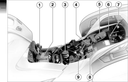
Underneath the seat
1 Height adjuster, front seat (b 53)
2 Battery (b 120)
3 Brake-fluid reservoir, rear (b 102)
4 Adjuster, spring preload, rear (b 55)
5 On-board toolkit (b 97)
6 Type plate
7 Helmet holder (b 54)
8 Table of tyre pressures
9 Label, payload
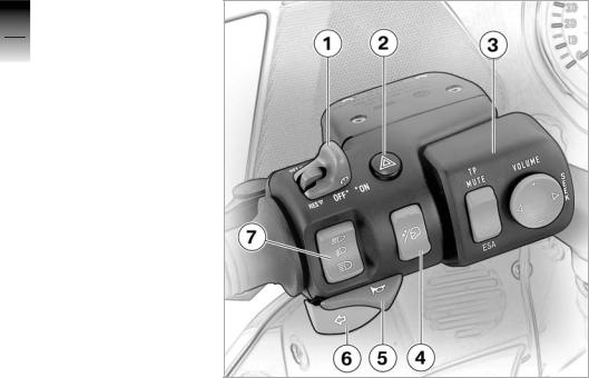
Handlebar fitting, left
11 Switch, cruise controlOE
(b 42)
2 Pushbutton, hazard warning flashers (b 37)
3 Radio operating panelOE
4 Pushbutton, windscreen adjustment (b 55)
5 Pushbutton, horn
6Pushbutton, left flashing turn indicators (b 50)
7Switch, high-beam headlight and headlight flasher (b 48)
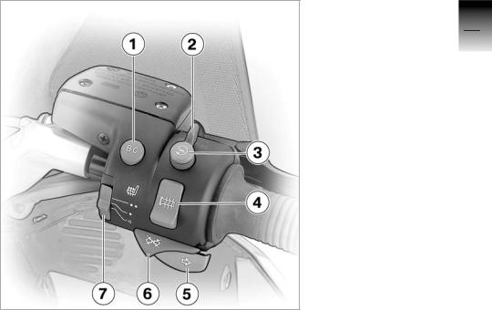
Handlebar fitting, right
1 Pushbutton, on-board computerOE (b 39)
2 Emergency off switch (kill switch) (b 45)
3 Pushbutton, starter
4Switch, grip heatingOE (b 45)
5Pushbutton, flashing turn indicators, right (b 50)
6Pushbutton, flashing turn indicators off (b 51)
7Switch, front-seat heatingOE (b 46)
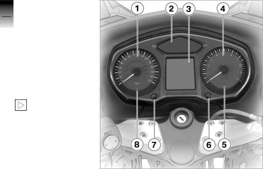
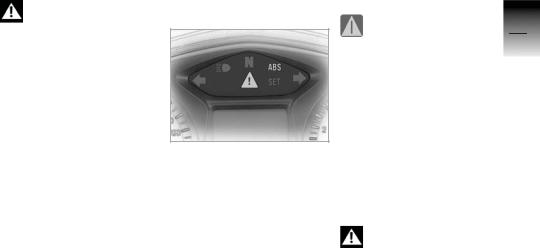
Instrument cluster
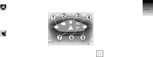
11 Speedometer
162 Warning and telltale lights (b 21)
Overview
3 Multifunction display (b 20)
4 Rev. counter
5Telltale light, anti-theft alarmOE
6 Adjuster, clock (b 38)
7 Control, odometer (b 37)
8Sensor, lights for instrument cluster
The instrument-cluster lighting has automatic
day and night switchover. The brightness of the night setting is variable (b 39).c

Headlight
|
1 |
High-beam headlight |
1 |
|
2 |
Low-beam headlight |
17 |
|
3 |
Side light |
|
|
Overview |

1
18
Overview
![]()
|
Multifunction display ……………….. |
20 |
|
Warning and telltale lights ……….. |
21 |
|
Warning indicators ………………….. |
21 |
|
ABS warnings ………………………… |
27 |
|
Status indicators |
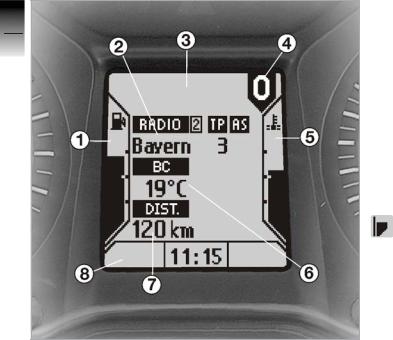
Multifunction display
1 Fuel gauge
2 Display, radioOE
3Display area for warning symbols
4 Gear indicator
5 Oil temperature gauge
6Display, on-board computerOE (b 39)
7 Odometer
8Display area for clock, seat heatingOE, display dimming.
Fuel capacity
The height of the bar indicates the level of fuel in
the fuel tank.
Gear indicator
The gear indicator shows which gear is selected. If
no gear is engaged, the gear indicator displays 0; the ’neutral’ telltale light also lights up.
Warning and telltale lights
Oil temperature
The height of the bar indicates the oil temperature.
1 Telltale light, left turn indicator
2 Telltale light, high-beam headlight
3 Telltale light, neutral
4 ABS warning light (or n depending on national-market specification)
5 Telltale light, right turn indicator
6Telltale light, cruise-control system
7 Warning light, general
Warning indicators
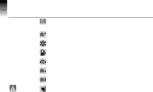
Warnings are displayed by means of symbols in the multifunction display. In some cases, an additional general warning light lights up red or yellow. A number of warnings may be issued simultaneously.
Warning lights and symbols in the display appear
only when the emergency off switch (b 45) (kill switch) is in the ’run’ position.c
Overview
2The warnings are listed in the table below, along with the page numbers of the pages you can refer to for more information.
|
22 |
Light |
Symbol |
Meaning |
Explanations |
Status indicators
 yellow
 yellow
 yellow
 yellow
|
Ignition key not authorised. |
(b 36) |
|
|
Low-beam headlight, high-beam |
||
|
headlight, side-light or turn-indicator |
||
|
bulb defective. |
(b 26) |
|
|
Ambient temperature below 3 °C |
||
|
(on-board computerOE) |
(b 26) |
|
|
Fuel down to reserve |
(b 24) |
|
|
Fault in the engine electronics |
(b 24) |
|
|
Rear light or brake light bulb defec- |
||
|
tive |
(b 26) |
|
|
Front/rear bulbs defective |
(b 26) |
|
red |
Engine-oil temperature too high |
(b 24) |
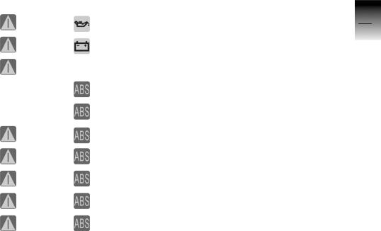
|
Light |
Symbol |
Meaning |
Explanations |
|
red |
Engine-oil pressure too low |
(b 25) |
|
|
red |
Battery is no longer being charged |
(b 26) |
|
|
red |
Brake switch defective |
(b 27) |
|
|
1 flash per |
|||
|
second |
ABS pull-away test not completed |
(b 28) |
|
|
4 flashes per |
|||
|
second |
ABS self-diagnosis not completed |
(b 28) |
|
|
Relay for ABS warning lights |
|||
|
red |
defective |
(b 28) |
|
|
1 flash per |
|||
|
red |
second |
ABS function not available |
(b 29) |
|
4 flashes per |
|||
|
red |
second |
ABS in residual braking mode |
(b 29) |
|
1 red flash |
1 flash per |
||
|
per second |
second |
Insufficient brake fluid |
(b 30) |
|
4 red flashes |
4 flashes per |
||
|
per second |
second |
Two or more ABS faults |
(b 31) |

Electronic immobiliser
Immobiliser symbol is displayed.
The key being used is not authorised for starting, or communication between key and engine electronics is disrupted.
•Remove all other vehicle keys located near the ignition key (b 34).
•Use the reserve key.
•Have the defective key replaced, preferably by an authorised BMW motorcycle dealer (b 36).
Fuel reserve
General warning light lights up yellow.
Fuel reserve symbol is displayed and flashes
10 times.
The fuel tank contains a fuel reserve of a maximum of
4 litres. The on-board computer shows the estimated residual operating range (b 39) .
Lack of fuel can result in the engine cutting out un-
expectedly and this could result in a hazardous situation. Do not run the fuel tank dry.c
Lack of fuel could result in misfiring and this in
turn could damage the catalytic converter.
Do not run the fuel tank dry.c
• Refuel.
Oil temperature
General warning light lights up red.
Oil temperature gauge flashes 10 times.
Oil temperature too high.
Continuing to ride with the engine overheated can
result in engine damage.c
•If possible, ride in the partload range to cool down the engine.
•Switch off the engine if you are caught in a traffic jam.
Engine electronics
General warning light lights up yellow.
Engine electronics symbol is displayed.
Fault in the engine electronics. In exceptional cases, the engine stops and can no longer be started. Otherwise, the engine runs in emergency operating mode.
You can continue to ride, but bear in mind that the usual engine output is not available.
The engine is running in emergency operating
mode. Engine power might be reduced and this can cause hazardous situations, particularly if you attempt to overtake other road users.
Adapt your style of riding to the reduced level of engine power.c
Engine oil pressure
General warning light lights up red.
Engine oil pressure symbol is displayed.
Insufficient engine oil pressure The «engine oil pressure» warning indicates that there is no oil pressure or that the oil
pressure in the lubricating oil circuit is too low; under no circumstances is it to be regarded as fulfilling the function of an oil gauge. The warning must disappear when oil pressure builds up 1 to 2 seconds after the engine starts.
If the «engine oil pressure» warning is displayed while the motorcycle is being ridden, take account of the traffic situation and:
•Disengage the gear.
•Operate the kill switch.
•Bring the motorcycle safely to a halt.
•Check the engine oil level.
There are other enginerelated problems besides
a low engine-oil level that can trigger the «engine-oil pressure» warning. Continuing to ride in these cases can cause engine damage.
If the «engine oil pressure» warning is issued, do not continue to ride if a check shows that the engine oil level is correct.c
•Have the fault rectified by a specialist workshop, preferably an authorised
BMW motorcycle dealer.
Battery charge current
2General warning light lights up red.
26Battery charge current symbol is displayed.
|
indicators |
The battery is no longer being |
|
|
charged. You can continue to |
||
|
ride only until the battery is |
||
|
discharged. |
||
|
Status |
A discharged battery can |
|
|
result in the engine cut- |
||
|
ting out unexpectedly, causing |
||
|
a hazardous situation. |
||
|
If possible, do not continue |
||
|
your journey.c |
||
|
• Have the fault rectified as |
||
|
soon as possible by a spe- |
||
|
cialist workshop, preferably |
||
|
an authorised |
||
|
BMW motorcycle dealer. |
Defective bulb
A defective bulb places your safety at risk be-
cause it is easier for other users to oversee you and your motorcycle.
Replace defective bulbs as soon as possible; always carry a complete set of spare bulbs if possible.c
General warning light lights up yellow. Defective bulb symbol with arrow pointing to the
rear is displayed.
Rear light or brake light bulb defective.
• Replace bulbs (b 116).
Defective bulb symbol with arrow pointing to the
front is displayed.
Low-beam headlight, highbeam headlight, side-light or turn-indicator bulb defective.
• Replace bulbs (b 112).
General warning light lights up yellow. Defective bulb symbol with two arrows is dis-
played.
A combination of the bulb defects described above has occurred.
• Replace bulbs (b 112).
Ice warning
Symbol for ice warning is displayed (motorcycle
with on-board computerOE only).
The air temperature measured at the motorcycle is lower than 3 °C: Risk of black ice.
The ice warning does not mean that there is no risk of black ice forming at meas-
ured temperatures above 3 °C. Always take extra care when temperatures are low and think well ahead; remember that the danger of black ice is particularly high on bridges and where the road is in the shade.c
ABS warnings
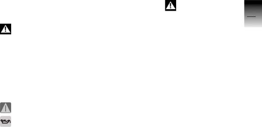
ABS warnings are indicated by a combination of the general warning light and the ABS warning light (or n depending on national-market specification). Both warning lights can light up continuously or flash at a rate of one or four flashes per second.
General warning light
General warning light red.
Brake switch defective or incorrectly adjusted. BMW Integral ABS detects the driver’s braking request by the pressure build-up from the brake lever. There may be an unusual response from the brakes. You can continue to ride. However, bear in mind that the brakes may respond in a manner to which you are not accustomed.
There is a defect in the brake system that can
lead to abnormal braking. Think well ahead and brake carefully; avoid severe braking.c
• Have the fault rectified as
2soon as possible by a specialist workshop, preferably
28an authorised
BMW motorcycle dealer.
|
indicators |
ABS warning light |
|
|
ABS warning light flashes |
||
|
once per second. |
||
|
ABS function not available |
||
|
Status |
because pull-away test (b 69) |
|
|
not completed. |
||
|
You can continue to ride. To |
||
|
prevent the wheels from lock- |
||
|
ing: |
||
|
• Do not use emergency brak- |
||
|
ing until the pull-away test |
||
|
has been completed. |
||
|
Without the ABS func- |
||
|
tion, the wheels could |
||
|
lock under braking. |
Think well ahead and brake carefully; avoid severe braking.c
ABS warning light flashes four times per second.
Only residual braking function available in both brake circuits, because self-diagnosis (b 65) has not completed. You can continue to ride. However, bear in mind that until self-diagnosis has completed, neither the ABS function nor the brake booster is available.
Without the ABS function, the wheels could lock under braking; without
servo-assisted brakes, considerably greater force is required to brake.
Think well ahead and brake carefully; avoid severe braking.c
•If circumstances permit, do not apply the brakes until self-diagnosis has completed.
General warning light and ABS warning light
General warning light red.
 ABS warning light ON.
The controller of the ABS warnings is defective. ABS faults cannot be displayed. You can continue to ride, but bear in mind that you will not receive warning of ABS faults, if they occur.
![]()
ABS warnings not available. ABS faults cannot be
indicated.
Think well ahead and brake carefully; avoid severe braking.c
•Have the fault rectified as soon as possible by a specialist workshop, preferably an authorised
BMW motorcycle dealer.
General warning light red.
ABS warning light flashes once per second.
ABS function (b 81) unavailable in at least one brake circuit.
You can continue to ride. However, bear in mind that the ABS function is not available.
Without the ABS function, the wheels could
lock under braking.
Think well ahead and brake carefully; avoid severe braking.c
•Have the fault rectified as soon as possible by a specialist workshop, preferably an authorised
BMW motorcycle dealer.
General warning light red.
ABS warning light flashes 4 times per second.
Only residual braking function (b 83) available in at least one brake circuit.
You can continue to ride. However, bear in mind that neither the ABS function nor the brake booster is available.
Without the ABS function, the wheels could lock under braking; without
servo-assisted brakes, considerably greater force is required to brake.
Think well ahead and brake carefully; avoid severe braking.c
•Have the fault rectified as soon as possible by a specialist workshop, preferably an authorised
BMW motorcycle dealer.

General warning light 2 flashes red once per
second.
30ABS warning light flashes once per second.
|
indicators |
Fluid level in at least one wheel |
||
|
brake circuit too low. |
|||
|
The ABS wheel brake cir- |
|||
|
cuit is a closed system; |
|||
|
Status |
you cannot check the fluid lev- |
||
|
el in this circuit at the brake- |
|||
|
fluid reservoirs.c |
|||
|
Several factors, including very |
|||
|
badly worn brake pads, can |
|||
|
trigger this warning. |
|||
|
Worn brake pads can |
|||
|
lengthen braking dis- |
|||
|
tance by a significant margin. |
|||
|
Think well ahead and brake |
|||
|
carefully; avoid severe |
|||
|
braking.c |
Worn brake pads can damage the brake discs.
Think well ahead and brake carefully; avoid severe braking.c
•Stop and check the thickness of the brake pads (b 100).
•Have worn brake pads replaced as soon as possible by a specialist workshop, preferably an authorised BMW motorcycle dealer.
If brake pad thickness is sufficient:
•Check the following functions:
–Ignition off, brake pressure present at the brake levers.
–Brakes acting on both wheels.
–Brake system leaktight, no signs of brake fluid escaping.
If any of the above criteria is not satisfied:
There is a defect in the brake system.
Do not continue to ride.c
If these criteria are satisfied, you can continue riding. However, bear in mind that a loss of brake fluid that cannot be detected might be the cause of the warning.

There is a fault in the brake system that can
lead to decreased braking efficiency.
Think well ahead and brake carefully; avoid severe braking.c
•Have the fault rectified as soon as possible by a specialist workshop, preferably an authorised
BMW motorcycle dealer.
General warning light flashes red four times per
second.
ABS warning light flashes four times per second.
There are two faults:
–Only residual braking function (b 83) available in at least one brake circuit, indicated by the general warning light and the ABS warning light flashing 4 times per second.
–Fluid level in the BMW Integral ABS is too low, indicated by the general and ABS warning lights flashing once per second.
See the fault descriptions above.

2
32
Status indicators

|
Ignition switch and steering |
|
|
lock ………………………………………… |
34 |
|
Electronic immobiliser …………….. |
36 |
|
Hazard warning flashers ………….. |
37 |
|
Odometer and tripmeters ………… |
37 |
|
Clock ……………………………………… |
38 |
|
Display dimming ……………………… |
39 |
|
On-board computerOE …………….. |
39 |
|
Cruise controlOE ……………………… |
42 |
|
Emergency off switch |
|
|
(kill switch) ……………………………… |
45 |
|
Grip heatingOE ………………………… |
45 |
|
Seat heatingOE…………………………. |
46 |
|
Handlebar levers …………………….. |
47 |
|
Lights ……………………………………… |
48 |
|
Turn indicators ……………………….. |
50 |
|
Stowage compartment ……………. |
51 |
|
Front and rear seats ………………… |
52 |
|
Helmet holder …………………………. |
54 |
|
Mirrors ……………………………………. |
55 |
|
Windscreen …………………………….. |
55 |
|
Spring preload ………………………… |
55 |
|
Shock absorbers …………………….. |
56 |
|
Wheels ……………………………………. |
57 |
|
Operation |

Ignition switch and steering lock
Keys
You receive one master key and one spare key. If a key is lost, please note the information on the electronic immobiliser (EWS) (b 24).
Ignition switch and steering lock, tank filler cap
lock and the seat and case locks are all operated with the same key. The topcaseOA is available in two different sizes; if you wish you can arrange to have the topcase fitted with a lock that can be opened with this key as well.c
Switching on the ignition Switching off the ignition
• Turn the key to the U position.
»Side lights and all function circuits switched on.
»Pre-ride check is performed (b 63).
»ABS self-diagnosis is performed (b 65).
»Engine can be started.
• Turn the key to the V position.
»Ignition and lights are switched off.
»The radio remains operational for a limited period of
time (see the operating instructions for the radioOE).
»Electrically powered accessories remain operational for a limited period of time
(b 87).

»The battery can be recharged via the on-board socket (b 120).
»Handlebars not locked.
»The key can be removed in this position.
Brake servo assistance is not available when the
ignition is off.
Do not switch off the ignition while the motorcycle is being ridden.c
If the motorcycle is laid up for a prolonged period
with the ignition lock in this position, recharge the battery every four weeks (b 120).c
Locking the handlebars
•Turn the handlebars to the full left or right lock position.
•Turn the key to the 1 posi-
tion for OFF, while moving the handlebars slightly.
»Ignition, lights and all function circuits switched off.
»Handlebars locked.
»In this position, you can remove the key.
|
If the motorcycle is laid |
3 |
||
|
up for a prolonged period |
|||
|
with the ignition lock in this po- |
|||
|
35 |
|||
|
sition, recharge the battery |
|||
|
every two months (b 120).c |
|||
|
When you prop the mo- |
Operation |
||
|
it is better to turn the handle- |
torcycle on the side stand, the surface of the ground will determine whether
bars to the left or right. On level ground, a secure stance is ensured only with the handlebars turned to the left.
On level ground, always turn the handlebars to the left and lock them in this position.c

Electronic immobiliser
The electronic immobiliser helps protect your BMW motorcycle from theft, and this enhanced security is at your disposal without any need for you to set parameters or activate additional systems. The engine of a motorcycle fitted with this electronic immobiliser can be started only with the keys that belong to the vehicle. You can also have your authorised BMW motorcycle dealer bar individual keys, for example if a key goes missing. The engine cannot be started with a key that has been barred.
In-key security
An electronic component is integrated into each of your keys. The motorcycle’s electronics exchange certain continuously changing signals with the electronics in the key; these signals are specific to your motorcycle and they are transmitted via the ring aerial in the ignition lock. The ignition is not enabled for starting until the key has been recognised as authorised for your motorcycle.
A spare key attached to the same ring as the igni-
tion key used to start the engine could «upset» the electronics, in which case the enabling signal for starting is not issued.The «EWS» warning is displayed in
the multifunction display. Always keep the spare key separately from the ignition key.c
Replacement and extra keys
You can obtain replacement/ extra keys only through an authorised BMW motorcycle dealer. The keys are part of an integrated security system, so the dealer is under an obligation to check the legitimacy of all applications for replacement/ extra keys.
If you want to have a lost key barred, you have to bring with you all the keys that belong to the motorcycle. A key that has been barred can subsequently be cleared and reactivated for use.

Hazard warning flashers
Switching on the hazard warning flashers
•Switch on the ignition.
•Press hazard warning flashers button 1.
»Hazard warning flashers in operation.
»Left/right turn indicator tell-
tale lights flash.
• Switch off the ignition.
»The hazard warning flashers continue to operate.
»Left/right turn indicator telltale lights off.
You can also switch on the hazard warning flash-
ers by simultaneously pressing the buttons for the left and right turn indicators.c
The hazard warning flashers place a strain
on the battery. Do not use the hazard warning flashers for longer than absolutely necessary.c
Switching off the hazard warning flashers
• Press hazard warning flashers button 1.
»Hazard warning flashers cease to operate.
Switching on a turn signal temporarily deactivates
the hazard warning flashers. The hazard warning flashers switch on again as soon as the turn signal is cancelled.c
Odometer and tripmeters
Odometer
The odometer reading appears in display field 1.

Selecting the tripmeter
• Switch on the ignition.
When you switch on the ignition, the tripmeter
reading shown when the ignition was switched off reappears on the multifunction display.c
•Briefly press tripmeter button 3 once.
»The following alternate in display field 2:
–Tripmeter 1 (Trip I)
–Tripmeter 2 (Trip II)
If your motorcycle is fitted with an on-board computerOE
(b 39), the tripmeter readings in display field 1 alternate with the odometer reading.
Resetting the tripmeter
•Switch on the ignition.
•Select the desired tripmeter.
•Press tripmeter button 3 and hold it down for longer than 2 seconds.
»The tripmeter is reset to zero.
Clock
Attempting to set the clock while riding the mo-
torcycle can lead to accidents. Set the clock only when the motorcycle is stationary.c
• Switch on the ignition.
• Press button 1 for longer than 2 seconds.
»Hours reading 2 starts to flash.
![]()
• Briefly press button 1.
»The hour increments by one each time you press the but-
ton.
• Press button 1 for longer than 2 seconds.
»Minutes reading 3 starts to flash.
• Briefly press button 1.
»The minute increments by one each time you press the button.
•Press button 1 for longer than 2 seconds.
» Setting confirmed.
Display dimming
The brightness of the backlit multifunction display is variable.
• Press button 1.
» The level of dimming appears in display field 2.
• Press button 1 again.
»The brightness of the display increases one level each time you press the button. Each time you press the button after maximum brightness is reached, brightness is reduced by one level.
On-board computerOE
|
Selecting readings |
3 |
|
|
• Switch on the ignition. |
39 |
|
|
Operation |
||
|
• Briefly press BC button 1. |

»Each time you press the button, display field 2 cycles through the following readings:
–Residual range
–Average speed
–Average consumption
–Oil level
–Ambient temperature
Residual range
Residual range is calculated on the basis of your style of riding and the amount of fuel left in the tank; the reading indicates the estimated distance you can travel before the fuel supply runs out.
If the motorcycle is resting on its side stand, the level in the tank cannot be measured correctly, so this estimate of residual operating range will be inaccurate.
When you refuel (ignition switched off) the on-board computer does not register the increase in fuel level unless more than 2 litres are added to the fuel already in the tank. The tank must contain at least 5 litres of fuel for the fuelgauge reading and the residual range to be recalculated.
The residual range is only an approximate reading. Consequently, you should not try to use the full residual range before refuelling.
Average speed
Elapsed time since the last «RESET» is used as the basis for calculating average speed. Times during which the engine was stopped are excluded from the calculation.

Resetting average speed Resetting average consumption
•Repeatedly press BC button 1 until the average speed appears in the display.
•Hold the BC button down for at least 2 seconds (RESET).
»The display shows «—.- km/h»
•Repeatedly press the BC button until the average consumption appears in the display.
•Hold the BC button down for at least 2 seconds (RESET).
»The display shows «—.- l/100 km»
Oil level check
Average consumption
Average consumption is calculated by dividing the distance covered since the last RESET by the corresponding amount of fuel used.
The «Oil» reading gives you an indication of the engine oil level. The preconditions for the oil level check are as follows:
–Engine idling (for at least 10 seconds)
–Engine at operating temperature
–Side stand retracted
The readings mean:
 Oil level is correct.
Check the oil level (b 98).
Oil level cannot be measured (conditions as
stated above not satisfied).
The most recently measured level is displayed for 5 seconds when you next switch on the ignition.

The oil-level sensor might be faulty if «Check the oil
level» appears in the display and does not go out, although a check of the oil sight glass shows that the oil level is correct.
Under these circumstances, contact your authorised BMW motorcycle dealer.c
Ambient temperature
The current ambient temperature is displayed. An ice warning (b 26) appears if the ambient-temperature reading drops below 3 °C. The display automatically switches from any other mode to the temperature reading when the temperature drops below this threshold for the first time. The reading flashes until you select some other display mode.
Cruise controlOE |
Setting road speed |
Activating the system
• Set switch 1 to ON.
»Red telltale light 2 in the switch lights up.
•Briefly push button 3 in the SET direction (arrow).

»The yellow SET telltale light of the cruise control system lights up.
»The motorcycle maintains your current cruising speed and the setting is saved.
Step-by-step acceleration
•Briefly push button 3 in the SET direction
»Speed is increased by approx. 2 km/h each time you push the button, and the new setting is saved.
Stepless acceleration
•Push button 3 in the SET direction (arrow) and hold it
in this position.
» The motorcycle accelerates steplessly.
• Release button 3.
»The motorcycle maintains your current cruising speed and the setting is saved.
Step-by-step deceleration
•Briefly push button 3 in the RES direction (arrow).
»Speed is decreased by approx. 2 km/h each time you push the button, and the new setting is saved.
Stepless deceleration
• Push button 3 in the RES direction (arrow) and hold it in this position.
»The motorcycle decelerates steplessly and the new setting is saved.

Deactivating the system
When you actuate the:
–Brakes
–Clutch
–Throttle twistgrip (turn the
twistgrip back past the normal closed-throttle position)
the cruise-control system is deactivated.
»The yellow SET telltale light of the cruise control system goes out.
»The red telltale light in the switch remains on.
Resuming former cruising speed
• Push button 3 in the RES direction.
»The yellow SET telltale light of the cruise control system lights up.
»The motorcycle resumes the previous cruising speed and this setting is saved.
Opening the throttle does not deactivate the cruise-
control system. If you release the twistgrip the motorcycle will decelerate only to the cruising speed saved in memory, even though you might have intended slowing to a lower speed.c
Deactivating the system
• Move switch 1 to OFF.
»The system is deactivated.
»Button 3 is locked.

Emergency off switch (kill switch)
Emergency off switch 1 is a kill switch for switching off the engine during or after a fall.
Operating kill switch 1 when riding can cause
the rear wheel to lock, provoking a fall.
Do not operate the kill switch when riding.c
•Turn kill switch 1 to left or right to position B.
»The engine electronics control unit switches the engine off.
»The radioOE is switched off.
»The engine cannot be started while the switch is in this position.
If you move the kill switch to the B position while
the ignition is switched on, the BMW Integral ABS remains operational (b 81).c
Grip heatingOE
Grip heating can be activated only when the engine is running. The increase in
power consumption caused by the grip heating can drain the battery if you are riding at low engine speeds. If the charge level is low, grip heating is switched off to ensure the battery’s starting capability.c
1 Grip heating switch

2 Heating off
3 50% heating power (one dot)
4100% heating power (three dots)
Seat heatingOE
Seat heating can be activated only when the en-
gine is running. The increase in power consumption caused by the heating can drain the battery if you are riding at low engine speeds. If the charge
level is low, the heating is switched off to ensure the battery’s starting capability.c
When the seat heating is on, bottom display field 1 contains a symbol for the front seat (left) and the rear seat (right), indicating the heating power for each seat.
–One dot:
50 % heating power
–Two dots:
100 % heating power
Seat heating, front seat
1Switch for seat heating, front seat
2 Heating off
3 50 % heating power
4 100 % heating power

Seat heating, rear seat
1Switch for seat heating, rear seat
2Switch in centre position: Heating off
3Pushed back:
100 % heating power
4Pushed forward:
50 % heating power
Switching on the grip heating or the seat heat-
ing or some other heavy electrical consumer can cause a sudden drop in the voltage in the motorcycle’s electrical system. In order to ensure the voltage supply under these circumstances, idle speed is temporarily increased to up to 1300 rpm. c
Handlebar levers
Adjusting the clutch lever
Attempting to adjust the clutch lever while riding
the motorcycle can lead to
accidents. Adjust the clutch
lever only when the motor- 3
cycle is stationary.c
47
Operation
•The distance between handlebar grip and clutch lever can be adjusted to any of
three positions by means of adjuster A.
»Position 1: minimum span
»Position 3: maximum span

Adjusting the handbrake lever
Attempting to adjust the brake lever while riding
the motorcycle can lead to accidents.
Adjust the brake lever only when the motorcycle is stationary.c
•The distance between handlebar grip and brake lever can be adjusted to any of four positions by means of adjuster B.
»Position 1: minimum span
»Position 4: maximum span
Lights
Side lights
The side lights switch on automatically when the ignition is switched on.
The side lights are a strain on the battery. Do not
switch the ignition on for longer than absolutely necessary.c
Low-beam headlight
The low-beam headlight switches on automatically when you start the engine.
With the engine switched off, you can switch on the
lights by switching on the
high-beam headlight with the ignition switched on or by operating the headlight flasher.c
High-beam headlight/ headlight flasher
•Press the top part of switch 1 for the high-beam headlight.
»High-beam headlight switched on.Move switch 1 for the high-beam headlight to the centre position.
»High-beam headlight switched off.
 Loading…
You can also use the index at
the end of this Rider’s Manual
to find a specific topic.
Overview . . . . . . . . . . . . . . . . . 6
Equipment . . . . . . . . . . . . . . . 7
Currency . . . . . . . . . . . . . . . . . 7
side . . . . . . . . . . . . . . . . . . . . . 13
Headlight . . . . . . . . . . . . . . . 19
lights . . . . . . . . . . . . . . . . . . . 23
indicators . . . . . . . . . . . . . . . 23
indicators . . . . . . . . . . . . . . . 29
EWS . . . . . . . . . . . . . . . . . . . . 39
flashers . . . . . . . . . . . . . . . . . 40
tripmeters . . . . . . . . . . . . . . . 41
Clock . . . . . . . . . . . . . . . . . . . 42
. . . . . . . . . 46
switch . . . . . . . . . . . . . . . . . . 48
Clutch . . . . . . . . . . . . . . . . . . 51
Brakes . . . . . . . . . . . . . . . . . . 52
Lights . . . . . . . . . . . . . . . . . . . 52
Headlight . . . . . . . . . . . . . . . 54
Mirrors . . . . . . . . . . . . . . . . . . 60
Windshield . . . . . . . . . . . . . . 61
Tires . . . . . . . . . . . . . . . . . . . . 65
5 Riding . . . . . . . . . . . . . . . . 67
Checklist . . . . . . . . . . . . . . . . 70
Starting . . . . . . . . . . . . . . . . . 70
. . . . 43
Running in . . . . . . . . . . . . . . 73
motorcycle . . . . . . . . . . . . . . 75
. . . . . 49
. . . . . . . . . . 49
. . . . . . . 63