- Manuals
- Brands
- Burkert Manuals
- Measuring Instruments
- 8025 Series
- Operating instructions manual
Flowmeter
-
Contents
-
Table of Contents
-
Troubleshooting
-
Bookmarks
Quick Links
Types 8025 / 8035
Flowmeter
Durchflussmessgerät
Débitmètre
Operating Instructions
Bedienungsanleitung
Manuel d’utilisation
Related Manuals for Burkert 8025
Summary of Contents for Burkert 8025
-
Page 1: Operating Instructions
Types 8025 / 8035 Flowmeter Durchflussmessgerät Débitmètre Operating Instructions Bedienungsanleitung Manuel d‘utilisation…
-
Page 2
We reserve the right to make technical changes without notice. Technische Änderungen vorbehalten. Sous réserve de modifications techniques. ©Bürkert SAS, 2013 — 2015 Operating Instructions 1503/2_EU-ML 00562780 Original FR… -
Page 3: Table Of Contents
Type 8025 / 8035 About this mAnuAl ………………………………..6 1.1. symbols used ………………………………… 6 Definition of the word «device» …………………………..6 1.2. intenDeD use ……………………………………. 7 bAsic sAfety informAtion …………………………….8 GenerAl informAtion ……………………………….. 9 manufacturer’s address and international contacts ……………………. 9 4.1. 4.2. Warranty conditions ………………………………9 information on the internet…………………………….9 4.3. Description ……………………………………10 5.1. Area of application ………………………………10 General description ………………………………10 5.2.
-
Page 4
Type 8025 / 8035 WirinG ……………………………………..27 8.1. making the installation equipotential ………………………..27 Wiring the 8025 compact version and the 8035 with a 4 pin male fixed connector ……….29 8.2. 8.3. configuring the selectors …………………………….30 8.3.1. FLOW SENSOR selector ……………………….30 8.3.2. SOURCE/SINK selector ……………………….30 8.3.3. 115/230 V AC selector ……………………….31 Wiring the 8025 in a compact version and the 8035, with or without relays, with cable glands ….31 8.4. 8.4.1. Wiring instructions …………………………31 8.4.2. Wiring of the relays (versions with relay output)………………..32 8.4.3. -
Page 5
Type 8025 / 8035 9.6.7. Configuring the filter of the measured flow rate ………………..55 9.6.8. Resetting both totalizers ……………………….55 9.7. Details of the test menu …………………………….56 9.7.1. Adjusting the OFFSET of the current output…………………. 56 9.7.2. Adjusting the SPAN of the current output ………………….57 9.7.3. Reading the rotational frequency of the paddle wheel………………57 9.7.4. Checking the outputs behaviour ……………………… 57 10. mAintenAnce AnD troubleshootinG …………………………58 10.1. safety instructions ………………………………58 10.2. cleaning the device ………………………………58 10.3. if you encounter problems …………………………….58 spAre pArts AnD Accessories …………………………..60 11. 11.1. spare parts 8025, compact version …………………………60 11.2. spare parts 8035…………………………………61… -
Page 6: About This Manual
Type 8025 / 8035 Aboutthismanual AbouT This mAnuAl This manual describes the entire life cycle of the device. Please keep this manual in a safe place, accessible to all users and any new owners. this manual contains important safety information. Failure to comply with these instructions can lead to hazardous situations. • This manual must be read and understood. 1.1. symbols used danger Warns against an imminent danger. • Failure to observe this warning can result in death or in serious injury. Warning Warns against a potentially dangerous situation. • Failure to observe this warning can result in serious injury or even death. attention Warns against a possible risk. • Failure to observe this warning can result in substantial or minor injuries. note Warns against material damage. • Failure to observe this warning may result in damage to the device or system. Indicates additional information, advice or important recommendations. Refers to information contained in this manual or in other documents. → Indicates a procedure to be carried out. 1.2. Definition of the word «device»…
-
Page 7: Intended Use
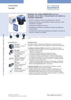
Type 8025 / 8035 Intendeduse inTenDeD use use of the device that does not comply with the instructions could present risks to people, nearby installations and the environment. • The compact version of the flowmeter type 8025 or 8035 is designed to measure the flow rate of a liquid and to totalise the volume of a liquid. • The remote version of the flowmeter type 8025 is a transmitter that must be connected to an 8020 or an 8030 flow sen- sor with a sinus or a pulse output, only in «Low Power» version. • This device must be protected against electromagnetic interference, ultraviolet rays and, when installed outdoors, the effects of climatic conditions. • This device must be used in compliance with the characteristics and commissioning and use conditions specified in the contractual documents and in the operating instructions. • Requirements for the safe and proper operation of the device are proper transport, storage and installation, as well as careful operation and maintenance. • Only use the device as intended. → Observe any existing restraints when the device is exported. English…
-
Page 8: Basic Safety Information
Type 8025 / 8035 Basicsafetyinformation bAsic sAfeTy informATion This safety information does not take into account: • any contingencies or occurences that may arise during installation, use and maintenance of the devices. • the local safety regulations for which the operating company is responsible including the staff in charge of installation and maintenance. Danger due to electrical voltage. • Shut down the electrical power source of all the conductors and isolate it before carrying out work on the system. • Observe all applicable accident protection and safety regulations for electrical equipment. risk of injury due to high pressure in the installation. • Stop the circulation of fluid, cut off the pressure and drain the pipe before loosening the process connections. risk of injury due to high fluid temperatures. • Use safety gloves to handle the device. • Stop the circulation of fluid and drain the pipe before loosening the process connections. risk of injury due to the nature of the fluid. • Respect the prevailing regulations on accident prevention and safety relating to the use of hazardous products. Various dangerous situations To avoid injury take care: • not to use the device in explosive atmospheres. • not to use the device in an environment incompatible with the materials it is made of. • not to use the device for the measurement of gas flow rates. • not to subject the device to mechanical loads (e.g. by placing objects on top of it or by using it as a step).
-
Page 9: General Information
Type 8025 / 8035 Generalinformation GenerAl informATion 4.1. manufacturer’s address and international contacts To contact the manufacturer of the device, use following address: Bürkert SAS Rue du Giessen BP 21 F-67220 TRIEMBACH-AU-VAL You may also contact your local Bürkert sales office. The addresses of our international sales offices are available on the internet at: www.burkert.com 4.2. Warranty conditions The condition governing the legal warranty is the conforming use of the device in observance of the operating conditions specified in this manual. 4.3. information on the internet You can find the operating instructions and technical data sheets regarding the type 8025 or the type 8035 at: www.burkert.com. English…
-
Page 10: Description
(the electronic is located in a housing with cover, display and 2 cable glands). • A panel version of the 8025 is an electronic module (an electronic located in an open housing with display). • A wall-mounted version of the 8025 is an electronic module (an electronic integrated in a housing with cover, display and 3 cable glands). According to the version, the device requires a 12-36 V DC or a 115/230 V AC power supply. The electrical connection is carried out via a male fixed connector or on the terminal blocks of the electronic board: whether directly, whether via 2 or 3 cable glands. 5.3. measuring principle The circulation of fluid within the pipe causes the paddle wheel of the sensor to rotate. The flowmeter detects the rotation of the paddle-wheel and generates a signal which frequency f is proportional to the flow rate Q, using the formula f = KxQ. f = frequency in Hertz (Hz) K = K factor of the S020 or S030 fitting used, in pulse/litre Q = flow rate in litre/second 5.4. Available versions of the 8025 compact flowmeter All the compact versions of the flowmeter 8025 have: — a 4-20 mA current output; — a pulse output ; — two totalizers. supply voltage seals electrical connection relays sensor order code 12-36 V DC Male fixed connector Hall, short 418762 12-36 V DC…
-
Page 11: Available Versions Of The 8025 Panel-Mounted Transmitter
Terminal strips via 2 cable Hall, short 418431 glands 115/230 V AC Hall, long 418432 115/230 V AC Terminal strips via 2 cable Coil, short 418433 glands 115/230 V AC Coil, long 418434 Delivered with the device. 5.5. Available versions of the 8025 panel-mounted transmitter All the panel versions of the 8025 have: — a 4-20 mA current output; — a pulse output; — two totalizers. supply voltage relays electrical connection ur and csA recognized order code 12-36 V DC Terminal strips 418992 12-36 V DC Terminal strips yes 552725…
-
Page 12: Description Of The Name Plate
Type 8025 / 8035 Description ur and csA supply voltage electrical connection relays sensor order code recognized 12-36 V DC Terminal strips via 2 cable Coil 423916 glands 12-36 V DC Terminal strips via 2 cable Hall 444007 glands yes 553433 12-36 V DC Terminal strips via 2 cable Coil 423918 glands 115/230 V AC Terminal strips via 2 cable Hall 423922 glands 115/230 V AC Terminal strips via 2 cable Hall 423924 glands identified by the logo located on the name plate of the device.
-
Page 13: Technical Data
Type 8025 / 8035 Technicaldata TechnicAl DATA The following technical data are relevant for an 8025 compact or an 8035 flowmeter and for the remote 8025 flowmeter con- nected to a Bürkert flow sensor 8020 / 8030 in a «Low Power» version only. 6.1. conditions of use Ambient temperature • 8025 compact, 115/230 V AC, not UR or CSA recognized • -10 to 50 °C • 8035 compact, 115/230 V AC, not UR or CSA recognized • -10 to 50 °C • Other versions, not UR or CSA recognized • -10 to 60 °C • UR and CSA recognized versions • -10 to 40 °C Air humidity < 80%, non condensated Protection rating According to EN 60529 • 8025 compact, and 8035 • IP65, device wired and cable glands tightened and cover lid screwed tight. • 8025 compact and wall-mounted, 8035 • IP65, device wired, cable glands tightened, cover lid…
-
Page 14: General Data
Type 8025 / 8035 Technicaldata 6.3. General data Pipe diameter • 8025 flowmeter • DN20 (except for the DN specified p.22) to DN400 • 8025 transmitter (remote versions) • DN06 to DN400 • 8035 flowmeter • DN06 to DN65 Type of fitting • S020, for a compact 8025 • S030, for a 8035 Type of fluid • liquid • viscosity: max. 300 cSt • rate of solid particles: max. 1% Fluid temperature (compact versions) The fluid temperature may be restricted by the fluid pressure, the material the flow sensor is made of and the material the S020 or S030 fitting used is made of. See «Fig. 2» and «Fig. 3». • with fitting in PVC • 0 to +50 °C • with fitting in PP…
-
Page 15: Mechanical Data
PVC + PP PVC (PN10) PP (PN10) T (°C) A: range of use Fig. 2: Fluid temperature /pressure dependency curves for the 8025 compact version, depending on the material the S020 fitting is made of P (bar) Metal PVDF PVC + PP PVDF (PN10)
-
Page 16
• 8025, compact or panel versions • PC • 8025, wall-mounted versions • ABS • 8035 • PC Cover • 8025 compact versions or 8035 • PC (Cover with lid) • 8025 panel versions • PC • 8025, wall-mounted versions • ABS Front foil Polyester Screws (4) Stainless steel Male fixed connector and female connector (type 2508) Cable glands Fig. 4: Dimensions of 8025 compact flowmeter [mm] English… -
Page 17
Type 8025 / 8035 Technicaldata Tab. 1: Dimensions of 8025 compact flowmeter associated to an S020 fitting [height H in mm] Welding tab with radius, in stainless Tee fitting Saddle Spigot, in plastic steel DN20 DN25 DN32 DN40 DN50 DN65 DN80 DN100 DN110 DN125 DN150 DN180 DN200… -
Page 18
Type 8025 / 8035 Technicaldata Fig. 6: Dimensions [mm] of the electronic module of the 8025 flowmeter in a wall-mounted version Tab. 2: Dimension H [mm] of the 8035 depending on the DN of the S030 sensor-fitting h with s030 sensor-fitting Fig. 7:… -
Page 19: Electrical Data
Type 8025 / 8035 Technicaldata 6.5. electrical data 12-36 V DC power supply • filtered and regulated • SELV circuit (safety extra low voltage), with a safe energy level • oscillation rate: ±10 % Power source (not supplied) • limited power source according to paragraph 9.3 of EN 61010-1 standard • or class 2 source according to UL 1310/1585 and EN 60950-1 standards 115/230 V AC power supply • frequency • 50/60 Hz • supplied voltage • 27 V DC, regulated • current • max. 250 mA • integrated protection • 250 mA time-delay fuse • power…
-
Page 20: Specifications Of The Connected Flow Sensor
Type 8025 / 8035 Technicaldata 6.6. specifications of the connected flow sensor Sensor input • signal frequency • 2,5 to 400 Hz • pulse signal (Hall) • NPN, open collector • sinus signal (coil) • typical sensitivity of 35 mV peak-peak, at 252 Hz Sensor output • power supply • 10-34 V DC (V+ minus 2 V DC), 1 mA max. 6.7. electrical connection Version connection features With male fixed Female connector (type 2508 supplied) connector For the female connector type 2508 with order code 438811 and the female connector type 2509 (not supplied) with order code 162673, use a shielded cable.
-
Page 21: Installation
Type 8025 / 8035 Installation insTAllATion 7.1. safety instructions danger risk of injury due to electrical voltage. • Shut down the electrical power source of all the conductors and isolate it before carrying out work on the system. • Observe all applicable accident protection and safety regulations for electrical equipment. Warning risk of injury due to nonconforming installation. • The electrical and fluid installation can only be carried out by qualified and skilled staff with the appropriate tools. • Install appropriate safety devices (correctly rated fuse and/or circuit-breaker); for the versions with 115/230 V AC power supply, insert a protection device between phase and neutral. • Respect standard NF C 15-100 / IEC 60364. • Observe mounting instructions of the fitting. risk of injury due to unintentional switch on of power supply or uncontrolled restarting of the installation. • Take appropriate measures to avoid unintentional activation of the installation. • Guarantee a set or controlled restarting of the process subsequent to any intervention on the device. Warning risk of injury if the fluid pressure/temperature dependency is not respected. • Take account of fluid temperature-pressure dependency according to the nature of the materials the fitting is made of (see the technical data and the operating instructions of the fitting used). • Comply with the Pressure Directive 97/23/CE. protect this device against electromagnetic interference, ultraviolet rays and, when installed outdoors, the effects of the climatic conditions.
-
Page 22: Installation Of A Compact Version
Type 8025 / 8035 Installation 7.2. installation of a compact version 7.2.1. instructions for installing a compact version onto the pipe The 8025 flowmeter has to be inserted into an S020 fitting mounted on a pipe. The 8035 flowmeter has to be installed on the pipe using the S030 sensor-fitting. → Choose an S020 or S030 fitting appropriate to the velocity of the fluid inside the pipe: refer to the graphs below: Tab. 3: Flow rate/ fluid velocity/ DN of S020 fitting and of S030 sensor-fitting diagram…
-
Page 23
Type 8025 / 8035 Installation → Install the device on the pipe in such a way that the upstream and downstream distances are respected according to the design of the pipes, refer to standard EN ISO 5167-1 and «Fig. 8». flow direction 50 x DN 5 x DN 40 x DN 5 x DN With control valve Pipe with 2 elbows at 90° in 3 dimensions 25 x DN 5 x DN 20 x DN 5 x DN Pipe with 2 elbows at 90° Pipe with 1 elbow at 90° or 1 T-piece 18 x DN 5 x DN… -
Page 24: Installation Of The 8025 On The S020 Fitting
→ Insert the nut 3 on the fitting 5. → Insert the snap ring 2 into the groove 4. → Check that the seal 6 is correctly inserted on the flow sensor. → Insert the device 1 into the fitting. If the mounting is correctly done the device cannot be turned around anymore. → Hand lock the assembly with nut 3. Fig. 11: Installation of the 8025 on the S020 fitting 7.2.3. installation of the se35 electronic module onto the s030 sensor-fitting → Respect the installation instructions contained in the operating instructions of the fitting used. → Insert the electronic module 2 into the S030 sensor-fitting. → Fix with a 30° rotation. →…
-
Page 25: Installation Of A Panel Version Of The 8025 Flowmeter
Type 8025 / 8035 Installation 7.3. installation of a panel version of the 8025 flowmeter install the panel version of the device in a cabinet with a protection class at least ip54 to ensure a degree of pollution 2 inside the cabinet. → To cut the opening in the cabinet door, use the supplied cutting plan of the frontage of the electrical cabinet, respecting the dimensions indicated in «Fig. 13». Fig. 13: Dimensions [mm] of the electrical cabinet frontage cutting plan Screw Washer Seal Cable clip Fig. 14: Installation of a 8025, panel version →…
-
Page 26: Installation Of A Wall-Mounted Version Of The 8025 Transmitter
Type 8025 / 8035 Installation 7.4. installation of a wall-mounted version of the 8025 transmitter note risk of material damage if the cable glands are not tightly screwed on the housing • Before installing the wall-mounted housing on its support, tighten the nuts of the entry item of the cables glands at a torque of 1.5 Nm. The flow transmitter in a wall-mounted version has 4 holes in the bottom of the housing. → Remove the blanking strips covering the screws. FLOW Blanking strips ENTER 0..9 Nut of the entry item → Loosen the 4 screws and open the cover to get access to the holes [1]. 106 mm CURRENT Without SOURCE SINK With Supply PULSE 12..36Vdc…
-
Page 27: Wiring
Type 8025 / 8035 Wiring WirinG danger risk of injury due to electrical voltage. • Shut down the electrical power source of all the conductors and isolate it before carrying out work on the system. • Observe all applicable accident protection and safety regulations for electrical equipment. Insert the supplied stopper gaskets into the unused cable glands of a wall-mounted or a compact version to ensure the tightness of the device. Only move the selectors when the power supply is off. • Use a filtered and regulated 12-36 V DC power supply. The circuit has to be safety extra low voltage (SELV), with a safe energy level. • Make sure the installation is equipotential. See chap. «8.1». • Use shielded cables with an operating temperature limit of 80 °C minimum. • Do not install the cables near high voltage or high frequency cables; if a combined installation cannot be avoided, a minimum space of 30 cm should be respected. • Protect the power supply by means of a 300 mA fuse and a switch. • Protect the relays by means of a max. 3 A fuse and a circuit breaker (depending on the process). • Do not apply both a dangerous voltage and a safety extra-low voltage to the relays. 8.1. making the installation equipotential To ensure the equipotentiality of the installation (power supply — device — fluid): → Connect together the various earth spots in the installation to eliminate the potential differences that may occur between different earthes.
-
Page 28
12-36 V DC Power supply Metal pipes 12-36 V DC Valve, pump,… (or earth rings, not provided, Power supply inserted into the pipe) Plastic pipes *) If a direct earth connection is not possible, fit a 100 nF / 50 V capacitor between the negative power supply terminal and the earth. Fig. 16: 8025 in a compact version and 8035, equipotentiality skeleton diagram with metal or plastic pipes Power supply 8025 Panel or wall- mounted version 8030 Metal pipes 8025 Panel or wall- mounted version… -
Page 29: Wiring The 8025 Compact Version And The 8035 With A 4 Pin Male Fixed Connector
Type 8025 / 8035 Wiring 8.2. Wiring the 8025 compact version and the 8035 with a 4 pin male fixed connector 1: V+ (12-36 V DC) 2: Positive pulse output 3: L- ( 0 V DC) : Negative pulse output Fig. 18: Pin assignment of the 4 pin male fixed connector → Unscrew the nut 1 of the cable gland. → Remove the terminal block 3 from the housing 2.
-
Page 30: Configuring The Selectors
Type 8025 / 8035 Wiring → Wire the transistor output using one of the wiring plans of «Fig. 21». Wiring of the pulse output in npn mode Wiring of the pulse output in pnp mode Power supply Power supply 12-36 V DC 300 mA 12-36 V DC 300 mA — 5-36 V DC 5-36 V DC 8025: 8025: (*) If direct earthing is not possible, insert a 100 nF / 50 V condensator between the negative terminal of the voltage supply and the earth. Fig. 21: Wiring of the pulse output in NPN or PNP mode, of a compact version with male fixed connector 8.3.
-
Page 31: 115/230 V Ac Selector
230V Energize the device with a 230 V AC voltage. 115 V AC voltage. 115V Fig. 24: Supply voltage selector on a 115/230 V AC version 8.4. Wiring the 8025 in a compact version and the 8035, with or without relays, with cable glands 8.4.1. Wiring instructions Seal the unused cable gland using the stopper gasket supplied to make sure the device is tight. → Unscrew the nut of the cable gland.
-
Page 32: Wiring Of The Relays (Versions With Relay Output)
OUTPUT → Always secure the relays connection cables in the slots FLOW SENSOR COIL marked 3 (see «Fig. 25»). Load 1 Load 2 Fig. 26: Wiring of the relays 8.4.3. Wiring the 8025 compact version and the 8035, 12-36 V Dc, without relays, with cable glands → Before wiring the device, configure the selectors on the electronic board (see chap. «8.3»). terminal block 1 NC: not connected L+: positive power supply L-: negative power supply PE: wiring of the PE between the main board and the protection board…
-
Page 33: Wiring The 8025 Compact Version And The 8035, 12-36 V Dc, With Relays, With Cable Glands
Wiring, in NPN or PNP mode, of the pulse output of a compact version, 12-36 V DC, without relays, with cable glands 8.4.4. Wiring the 8025 compact version and the 8035, 12-36 V Dc, with relays, with cable glands →…
-
Page 34
Type 8025 / 8035 Wiring Wiring of the current output in sourcing mode Wiring of the current output in sinking mode 4-20mA input at exter- 4-20mA input at exter- Power supply nal instrument nal instrument Power supply 300 mA 300 mA 12-36 V DC 12-36 V DC Iout Iout Source/Sink selector Source/Sink selector (see chap. «8.3.2») (see chap. «8.3.2») Without Without SOURCE SINK SOURCE SINK With With Supply PULSE Supply PULSE 12..36Vdc… -
Page 35: Wiring The 8025 Compact Version And The 8035, 115/230 V Ac, Without Relays, With Cable Glands
Type 8025 / 8035 Wiring 8.4.5. Wiring the 8025 compact version and the 8035, 115/230 V Ac, without relays, with cable glands → Before wiring the device, configure the selector on the electronic board (see chap. «8.3»). terminal block 1 The red wire is wired on the NC terminal to make the wiring of the NC: not connected (terminal for the 4-20 mA output easier (see «Fig. 34»). The jumper wire 4 between L+ and wiring of the 4-20 mA output) NC energizes the NC terminal. L+ (red wire, factory wired) PE: wiring of the PE between the main board and the protection board L- (black wire, factory wired) P-: negative pulse output P+: positive pulse output Without With terminal block 2 pe Supply PULSE 12..36Vdc…
-
Page 36: Wiring The 8025 Compact Version And The 8035, 115/230 V Ac, With Relays, With Cable Glands
Fig. 35: Wiring, in NPN or PNP mode, of the pulse output of a 115/230 V AC compact version, without relays, with cable glands 8.4.6. Wiring the 8025 compact version and the 8035, 115/230 V Ac, with relays, with cable glands →…
-
Page 37
Type 8025 / 8035 Wiring 4-20mA input at external instrument Without SOURCE SINK With Supply PULSE 12..36Vdc OUTPUT FLOW SENSOR COIL T 125 mA 115/230 V AC power supply If the current output is wired, remove the jumper wire between the terminals Iout and L+. Fig. 37: Wiring in sourcing mode of the current output of a compact version, 115/230 V AC, with relays, with cable glands… -
Page 38: Connecting The Flow Sensor To The 8025 Transmitter, Panel-Mounted Version Or Wall-Mounted Version
1 2 3 4 PE flow sensor with a sinus output flow sensor with a pulse output (npn) NC = Not connected Fig. 40: Wiring of the remote flow sensor to the 8025 transmitter 8.6. Wiring the 8025 remote (wall-mounted or panel), 12-36 V Dc, with or without relays 8.6.1. Wiring the 8025, remote version, 12-36 V Dc, without relays →…
-
Page 39: Wiring The 8025, Remote Version, 12-36 V Dc, With Relays
Fig. 41: Terminal assignment of a panel-mounted or wall-mounted version, 12-36 V DC, without relays The wiring of the current output and the wiring of the pulse output of the panel or wall-mounted transmitter, 12-36 V DC, without relays, are the same as for a compact flowmeter, 12-36 V DC, without relays, with cable glands. → Wire the current output according to «Fig. 28» of chap. «8.4.3». → Wire the pulse output according to «Fig. 29» of chap. «8.4.3». 8.6.2. Wiring the 8025, remote version, 12-36 V Dc, with relays → For a wall-mounted version, obey the wiring instructions of chap. «8.7.1». → Before wiring the device, configure the selectors on the electronic board (see chap. «8.3»). → Connect the flow sensor to the transmitter according to chap. «8.5». terminal block 1…
-
Page 40: Wiring The 8025, Wall-Mounted Version, 115/230 V Ac, With Or Without Relays
Type 8025 / 8035 Wiring → Insert the cable clips: see «Fig. 25». The wiring of the current output and the pulse output of the panel or wall-mounted transmitter, 12-36 V DC, without relays, are the same as for a compact flowmeter, 12-36 V DC, with relays, with cable glands. → Wire the current output according to «Fig. 31» of chap. «8.4.4». → Wire the pulse output according to «Fig. 32» of chap. «8.4.4». 8.7. Wiring the 8025, wall-mounted version, 115/230 V Ac, with or without relays 8.7.1. Wiring instructions for a wall-mounted version Seal the unused cable gland using the supplied stopper gasket to make sure the device is tight. → Unscrew the nut of the cable gland. → Remove the transparent disc inside the cable gland. → Insert the stopper gasket →…
-
Page 41: Wiring The 8025, Wall-Mounted Version, 115/230 V Ac, Without Relays
Type 8025 / 8035 Wiring 8.7.2. Wiring the 8025, wall-mounted version, 115/230 V Ac, without relays → Before wiring the device, obey the instructions of chap. «8.7.1». terminal block 1 NC: not connected L+ (red wire, factory wired) L- (green wire, factory wired) PE: wiring of the PE between the main board and the protection board P- (brown wire, factory wired) P+ (white wire, factory wired) terminal block 2 pe Shield wiring (green/yellow wire, factory wired) time-delay fuse 3: fuse to protect the Without With 115 V AC or 230 V AC power supply Supply PULSE 12..36Vdc OUTPUT COIL SENSOR NPN SENSOR…
-
Page 42
Type 8025 / 8035 Wiring Without With Supply PULSE 12..36Vdc OUTPUT COIL SENSOR NPN SENSOR FLOW SENSOR 1 PULSE INPUT COIL SUPPLY 3 NC 4 NC 4 NC 4 PE FLOW SENSOR 5 6 7 8 9 10 4-20mA input at external instrument Fig. -
Page 43
Type 8025 / 8035 Wiring Without With Supply PULSE 12..36Vdc OUTPUT COIL SENSOR NPN SENSOR FLOW SENSOR 1 PULSE INPUT COIL SUPPLY 3 NC 4 NC 4 NC 4 PE FLOW SENSOR 5 6 7 8 9 10 5-36 V DC Fig. -
Page 44: Wiring The 8025, Wall-Mounted Version, 115/230 V Ac, With Relays
Type 8025 / 8035 Wiring 8.7.3. Wiring the 8025, wall-mounted version, 115/230 V Ac, with relays → Before wiring the device, obey the instructions of chap. «8.7.1». terminal block 1 Iout: 4-20 mA output (green wire, factory wired) L+ (red wire, factory wired) L- (black wire, factory wired) PE: wiring of the PE between the main board and the protection board P- (brown wire, factory wired) P+ (white wire, factory wired) terminal block 2 pe Shield connection (green/yellow wire, factory wired) time-delay fuse 3: fuse to protect the CURRENT Without SOURCE SINK 115 V AC or 230 V AC power supply With Supply PULSE 12..36Vdc…
-
Page 45
Type 8025 / 8035 Wiring CURRENT Without SOURCE SINK With Supply PULSE 12..36Vdc OUTPUT COIL SENSOR NPN SENSOR FLOW SENSOR 1 PULSE INPUT COIL SUPPLY 3 NC 4 NC 4 NC 4 PE 3A/230VAC FLOW SENSOR 5 6 7 8 9 10… -
Page 46: Operating And Commissioning
Type 8025 / 8035 operatingandcommissioning operATinG AnD commissioninG 9.1. safety instructions Warning risk of injury due to nonconforming operating. Non-conforming operating could lead to injuries and damage the device and its surroundings. • The operators in charge of operating must have read and understood the contents of this manual. • In particular, observe the safety recommendations and intended use. • The device/installation must only be operated by suitably trained staff. Warning Danger due to non-conforming commissioning. Non-conforming commissioning could lead to injuries and damage the device and its surroundings. • Before commissioning, make sure that the staff in charge have read and fully understood the contents of the manual. • In particular, observe the safety recommendations and intended use. • The device / the installation must only be commissioned by suitably trained staff. • Before commissioning, set the K Factor of the fitting used. See chap. «9.6.3». 9.2. operating levels of the device The device has two operating levels: the Process level and the Configuration level. The Process level makes it possible: • to read the flow rate measured by the device, the value of the current transmitted on the 4-20 mA analogue output, the values of both the daily and main totalizers;…
-
Page 47
Type 8025 / 8035 operatingandcommissioning Process level Configuration level 12.6 L/MiN. > 5 s ENTER 16.45 MA 0..9 0..9 Parameters Menu Test Menu 87654 L ENTER OFFSEt LANGUAGE > 5 s UNit SPAN 231 L. K-FACtOR FREqUENC 0..9 CURRENt FLOw 0..9 > 2 s PULSE 0..9 To reset the daily totalizer (iden- tified by a dot after the volume RELAy units). -
Page 48: Description Of The Navigation Keys And The Status Leds
Type 8025 / 8035 operatingandcommissioning 9.3. Description of the navigation keys and the status leDs • Selecting the displayed parameter • Confirming the settings • Scrolling up the parameters • Incrementing the figure selected LED indicating the status of the relay (LED ON = contact closed) LED indicating the status of the relay 1 • Scrolling through the parameters (LED ON = contact closed) • Selecting the figure on the left Fig. 52: Description of the display 9.4. using the navigation keys you want to…
-
Page 49: Details Of The Process Level
Type 8025 / 8035 operatingandcommissioning 9.5. Details of the process level This level is active by default when the device is energized. Value of the measured flow rate, displayed in the unit chosen in the «UNIT» parameter of the 12.6 L/MiN. Parameters menu. Value of the current output, proportional to the measured flow rate. 16.45 MA 0..9 Value of the main totalizer, volume of fluid counted by the device since the last reset. 87654 L Value of the daily totalizer (identified by a dot after the volume units), volume of fluid counted by 231 L. the device since the last reset. Resetting the daily totalizer. 0..9 > 2 s Fig. 53: Diagram of the Process level 9.6. Details of the parameters menu…
-
Page 50: Choosing The Display Language
Type 8025 / 8035 operatingandcommissioning 9.6.1. choosing the display language When the device is energized for the first time, the display language is English. LANGUAGE ENGLiSh → ENTER DEUtSCh The chosen language is active as soon as the key is 0..9 pressed FRANçAiS itALiANO UNit Fig. 55: Diagram of the «LANGUAGE» parameter of the Parameters menu → ENTER If you do not want to adjust another parameter, go to the «END» parameter of the Parametersmenu and press to save the settings and go back to the Process level. 9.6.2.
-
Page 51
Type 8025 / 8035 operatingandcommissioning → Choose the flow rate unit. UNit FLOw RAtE Lit/SEC → Confirm. Lit/MiN Lit/h M3/MiN M3/h 0..9 ENTER US GAL/S DEC Pt 3 US GAL/M → Choose the number DEC Pt 2 0..9 0..9 of decimal positions. US GAL/h → Confirm. DEC Pt 1… -
Page 52: Entering The K Factor Of The Fitting Used
Type 8025 / 8035 operatingandcommissioning 9.6.3. entering the K factor of the fitting used The device determines the flow rate in the pipe using the fitting K factor. The K factor of the fitting used can be entered here. The device may also determine the K factor using a teach-in procedure: see «Fig. 58». The K factor of the fitting used is in the operating instructions of the fitting. The operating instructions of the Bürkert fittings can be found on the CD delivered with the device or on the internet at: www.burkert.com. The display shows the K factor of the fitting, ENTER ENTER last entered or determined using a Teach-In K-FACtOR tEACh NO K=0000.00 procedure. → Edit the parameter. 0..9 → Enter the K factor (value between 0,0001 and 9999,9) of the fitting used. ENTER CURRENt K=0117.60 → Confirm the displayed value.
-
Page 53: Configuring The Current Output
Type 8025 / 8035 operatingandcommissioning 9.6.4. configuring the current output The 4-20 mA output provides an electrical current, the value of which reflects the flow rate measured by the device. Example of relation between the measuring range and the current output: l/min → To invert the output signal, give a lower flow rate value to the 20 mA current value than to the 4 mA current value. → To disable the current output, set both range bounds, 4 and 20 mA, to zero. In this case the output delivers a constant current of 4 mA. The units and number of decimal digits are those set within the «UNIT» parameter for the display of the current output values. ENTER CURRENt 4=0000 → Enter the flow rate value related to the a 4 mA current, in the unit chosen in the 0..9 «UNIT».parameter. 4 = 28.00 20=0000 → Enter the flow rate value related to the a 20 mA current, in the unit chosen in the «UNIT» parameter. 0..9 ENTER PULSE 20 = 6.000 Fig.
-
Page 54: Configuring The Relays
Type 8025 / 8035 operatingandcommissioning 9.6.6. configuring the relays This parameter makes it possible to set the switching thresholds and the operating behaviour, inverted or not, of each relay. Enter values such as 1- ≤ 1+ and/or 2- ≤ 2+. Both relays work in an hysteresis operating. ENTER RELAy 1-= 0000 → Enter a flow rate value, associated to the low threshold of relays 1, in the unit chosen in the «UNIT» parameter. 0..9 → Confirm. ENTER 1-= 0008 1+ = 0000 → Enter a flow rate value, associated to the high threshold of relays 1, in the unit chosen in the «UNIT» parameter. 0..9 → Confirm. ENTER iNv NO 1+ = 0010 →…
-
Page 55: Configuring The Filter Of The Measured Flow Rate
Type 8025 / 8035 operatingandcommissioning Sense of operation not inverted Sense of operation inverted Contact Contact Inverted YES Inverted NO 1- (2-) (2+) 1- (2-) (2+) Flow rate Flow rate Fig. 62: Hysteresis operating 9.6.7. configuring the filter of the measured flow rate This parameter makes it possible to dampen the fluctuations: • of the display; • of the current output. Ten filters are available. The following table gives the response time for each filter (10% to 90%): FILTER…
-
Page 56: Details Of The Test Menu
Type 8025 / 8035 operatingandcommissioning The daily totalizer can be reset from the Process level. See chap. «9.4». → If you do not want to adjust another parameter, go to the «END» parameter of the Parameters menu and press ENTER to save the settings and go back to the Process level. 9.7. Details of the Test menu ENTER To access the Test menu, simultaneously press keys for at least 5 s. 0..9 This menu comprises the following configurable parameters: Adjusting the OFFSET of the current output. See chap. «9.7.1». OFFSEt Adjusting the SPAN of the current output. See chap. «9.7.2». SPAN 0..9 Reading the rotational frequency of the paddle wheel. See chap. «9.7.3». FREqUENC. Simulating a flow rate to check the correct operating of the outputs. See chap. «9.7.4». FLOw 12.6 L/MiN. Process level Go back to the Process level by saving the new OFFSET and SPAN adjustments. When «END» is confirmed and the display indicates «OFFSET»: enter new offser and/or span values. Fig. 65: Diagram of the Test menu 9.7.1.
-
Page 57: Adjusting The Span Of The Current Output
Type 8025 / 8035 operatingandcommissioning 9.7.2. Adjusting the spAn of the current output This parameter makes it possible to adjust the 20 mA current value transmitted on the 4-20 mA output. → Connect a multimeter into the measurement loop. → ENTER The device generates a 20 mA current. SPAN SP= 20.00 → Measure the current given on the 4-20 mA output using a multimeter. → 0..9 Enter the value displayed by the multimeter. The permitted span range is 15 to 21,50 mA. ENTER FREqUENC SP= 19.90 → Confirm. Fig. 67: Adjustment of the SPAN →…
-
Page 58: Maintenance And Troubleshooting
Type 8025 / 8035 Maintenanceandtroubleshooting mAinTenAnce AnD TroubleshooTinG 10.1. safety instructions danger Danger due to electrical voltage. • Shut down the electrical power source of all the conductors and isolate it before carrying out work on the system. • Observe all applicable accident protection and safety regulations for electrical equipment. risk of injury due to high pressure in the installation. • Stop the circulation of fluid, cut off the pressure and drain the pipe before loosening the process connections. risk of injury due to high fluid temperatures. • Use safety gloves to handle the device. • Stop the circulation of fluid and drain the pipe before loosening the process connections. risk of injury due to the nature of the fluid. • Respect the prevailing regulations on accident prevention and safety relating to the use of hazardous products. Warning risk of injury due to nonconforming maintenance. • Maintenance must only be carried out by qualified and skilled staff with the appropriate tools. • Guarantee a defined or controlled restarting of the process after a power supply interruption. 10.2. cleaning the device The device can be cleaned with a cloth dampened with water or a detergent compatible with the materials the device is made of. Please feel free to contact your Bürkert supplier for any additional information.
-
Page 59
Type 8025 / 8035 Maintenanceandtroubleshooting message possible cause recommended action displayed → ERROR 7 Memory read error: the user settings Press the ENTER key to acknowledge the error: the totalizers are and the totalizer values are lost. reset. → Send the device back to your supplier. → PWR FAIL The supply voltage is too low. Adjust the supply voltage so that the voltage at the device ter- minals is between 12 V and 36 V. • The voltage at the device terminals is lower than 12 V. • The impedance of the current measurement loop is too high (see chap. «6.5»). → PU H LIM The pulse value times the K factor of Enter a lower volume / pulse. See chap. «9.6.5». → the device is > 1000000. Check the K factor value. See chap. «9.6.3». The entered volume for a pulse is too high. → PU L LIM The pulse value times the K factor of Enter a higher volume / pulse. See chap. «9.6.5». -
Page 60: Spare Parts And Accessories
AnD Accessories attention risk of injury and/or damage caused by the use of unsuitable parts. Incorrect accessories and unsuitable replacement parts may cause injuries and damage the device and the surrounding area. • Use only original accessories and original replacement parts from Bürkert. The defective electronic board or housing of your device can be replaced. • Contact the local Bürkert office. 11.1. spare parts 8025, compact version Fig. 70: Exploded view of the spare parts of a 8025, compact version position fig. 70 Designation order code 115/230 V AC supply voltage board + replacement instructions 553168 Female connector with cable gland (type 2508) 438811 Female connector type 2509 with NPT 1/2 » reduction 162673 4+6+7+9 Set including: • 2 M20*1.5 cable glands…
-
Page 61: 11.2. Spare Parts 8035
Type 8025 / 8035 Sparepartsandaccessories position fig. 70 Designation order code 5+6+7 Set including: • 2 M20*1.5 / NPT1/2» reductions (with mounted seals) 551782 • 2 neopren flat seals for the screw plug • 2 M20*1.5 screw plugs 8+9+14 Set including: • 1 M20*1.5 cable gland stopper gasket • 1 2*6 mm multi-way seal for a cable gland 551775 • 1 black EPDM seal for the flow sensor • 1 mounting instruction sheet 10 + 2 Housing with female connector type 2508, snap ring and nut 425524 Housing for 2 M20*1.5 cable glands, snap ring and nut 425526 Snap ring 619205 619204 Set including: • 1 FKM green seal 552111 • 1 EPDM black seal…
-
Page 62: 11.3. Spare Parts, 8025 Panel-Mounted Version
10+2 Housing with female connector type 2508, coil function 425246 Housing for 2 M20*1.5 cable glands, coil function 425247 Housing for 2 M20*1.5 cable glands, Hall function 425248 Set with 8 FLOW foils 553191 11.3. spare parts, 8025 panel-mounted version Fig. 72: Exploded view of the spare parts of a 8025 panel-mounted version position fig. 72 Designation order code Mounting set (screws, washers, nuts, cable clips) 554807 Seal 419350 Set with 8 FLOW foils 553191 11.4. spare parts, 8025 wall-mounted version…
-
Page 63: Packaging, Transport
Type 8025 / 8035 Sparepartsandaccessories pAcKAGinG, TrAnsporT note Damage due to transport Transport may damage an insufficiently protected device. • Transport the device in shock-resistant packaging and away from humidity and dirt. • Do not expose the device to temperatures that may exceed the admissible storage temperature range. • Protect the electrical interfaces using protective plugs. sTorAGe note poor storage can damage the device. • Store the device in a dry place away from dust. • Storage temperature of the device: — 8025 compact, 115/230 V AC, not UR or CSA recognized: 0 to 50 °C — 8035 compact, 115/230 V AC, not UR or CSA recognized: 0 to 50 °C — other versions, not UR or CSA recognized: 0 to 60 °C — UR and CSA recognized versions: 0 to 40 °C. DisposAl of The proDucT → Dispose of the device and its packaging in an environmentally-friendly way. note Comply with the national and/or local regulations which concern the area of waste disposal. English…
-
Page 64
Type 8025 / 8035 Sparepartsandaccessories English…
This manual is also suitable for:
8035
-
manualzz.com
Инструкции и Руководства для Burkert 8025.
Мы нашли 37
инструкции доступные для бесплатного скачивания:
Инструкция по эксплуатации, Руководство пользователя, Техническая спецификация

Burkert 8035 Inline flowmeter or batch controller Руководство пользователя
Бренд:
Burkert
Размер:
3 MB
Страниц:
69
Язык(и):
Русский
Открыть в новой вкладке

Burkert 8035 Inline flowmeter or batch controller Руководство пользователя
Бренд:
Burkert
Размер:
3 MB
Страниц:
74
Язык(и):
Русский
Открыть в новой вкладке

Burkert 8025 Insertion flowmeter or batch controller Data Sheet
Бренд:
Burkert
Размер:
98 KB
Страниц:
1
Язык(и):
Английский
Открыть в новой вкладке
Burkert 8025 Insertion flowmeter or batch controller Data Sheet
Бренд:
Burkert
Размер:
2 MB
Страниц:
40
Язык(и):
Английский
Открыть в новой вкладке
Burkert 8200 Armatures Data Sheet
Бренд:
Burkert
Размер:
2 MB
Страниц:
24
Язык(и):
Английский
Открыть в новой вкладке
Burkert 8200 Armatures Ficha de datos
Бренд:
Burkert
Размер:
3 MB
Страниц:
24
Язык(и):
Испанский
Открыть в новой вкладке
Burkert 8025 Insertion flowmeter or batch controller Datenblatt
Бренд:
Burkert
Размер:
2 MB
Страниц:
40
Язык(и):
Немецкий
Открыть в новой вкладке
Burkert 8200 Armatures Datenblatt
Бренд:
Burkert
Размер:
2 MB
Страниц:
24
Язык(и):
Немецкий
Открыть в новой вкладке

Burkert SE35 Transmitter or batch controller User Manual
Бренд:
Burkert
Размер:
460 KB
Страниц:
42
Язык(и):
Английский
Открыть в новой вкладке

Burkert SE35 Transmitter or batch controller Operating Instructions
Бренд:
Burkert
Размер:
6 MB
Страниц:
144
Язык(и):
Английский
Открыть в новой вкладке

Burkert SE35 Transmitter or batch controller Operating Instructions
Бренд:
Burkert
Размер:
5 MB
Страниц:
88
Язык(и):
Английский
Открыть в новой вкладке

Burkert 8025 Insertion flowmeter or batch controller Operating Instructions
Бренд:
Burkert
Размер:
3 MB
Страниц:
70
Язык(и):
Английский
Открыть в новой вкладке

Burkert S020 Insertion fitting Operating Instructions
Бренд:
Burkert
Размер:
1 MB
Страниц:
40
Язык(и):
Английский
Открыть в новой вкладке

Burkert SE35 Transmitter or batch controller User Manual
Бренд:
Burkert
Размер:
3 MB
Страниц:
72
Язык(и):
Английский
Открыть в новой вкладке
Burkert SE35 Transmitter or batch controller User Manual
Бренд:
Burkert
Размер:
3 MB
Страниц:
66
Язык(и):
Английский
Открыть в новой вкладке

Burkert 8025 Insertion flowmeter or batch controller User Manual
Бренд:
Burkert
Размер:
2 MB
Страниц:
48
Язык(и):
Английский
Открыть в новой вкладке

Burkert 8200 Armatures Service Manual
Бренд:
Burkert
Размер:
449 KB
Страниц:
4
Язык(и):
Немецкий, Английский, Французский
Открыть в новой вкладке

Burkert 8035 Inline flowmeter or batch controller Benutzerhandbuch
Бренд:
Burkert
Размер:
5 MB
Страниц:
90
Язык(и):
Немецкий
Открыть в новой вкладке

Burkert 8035 Inline flowmeter or batch controller Benutzerhandbuch
Бренд:
Burkert
Размер:
6 MB
Страниц:
146
Язык(и):
Немецкий
Открыть в новой вкладке

Burkert 8035 Inline flowmeter or batch controller Benutzerhandbuch
Бренд:
Burkert
Размер:
558 KB
Страниц:
44
Язык(и):
Немецкий
Открыть в новой вкладке

Burkert 8025 Insertion flowmeter or batch controller Benutzerhandbuch
Бренд:
Burkert
Размер:
3 MB
Страниц:
72
Язык(и):
Немецкий
Открыть в новой вкладке

Burkert 8020 Insertion flowmeter Benutzerhandbuch
Бренд:
Burkert
Размер:
1 MB
Страниц:
42
Язык(и):
Немецкий
Открыть в новой вкладке

Burkert 8020 Insertion flowmeter Användarmanual
Бренд:
Burkert
Размер:
1 MB
Страниц:
42
Язык(и):
Шведский
Открыть в новой вкладке

Burkert 8035 Inline flowmeter or batch controller Manuale utente
Бренд:
Burkert
Размер:
4 MB
Страниц:
92
Язык(и):
Итальянский
Открыть в новой вкладке
Burkert 8025 Insertion flowmeter or batch controller User Manual
Бренд:
Burkert
Размер:
690 KB
Страниц:
38
Язык(и):
Открыть в новой вкладке

Burkert 8025 Insertion flowmeter or batch controller Manual de usuario
Бренд:
Burkert
Размер:
981 KB
Страниц:
48
Язык(и):
Испанский
Открыть в новой вкладке

Burkert 8035 Inline flowmeter or batch controller Benutzerhandbuch
Бренд:
Burkert
Размер:
3 MB
Страниц:
74
Язык(и):
Немецкий
Открыть в новой вкладке

Burkert 8035 Inline flowmeter or batch controller Benutzerhandbuch
Бренд:
Burkert
Размер:
3 MB
Страниц:
70
Язык(и):
Немецкий
Открыть в новой вкладке

Burkert 8025 Insertion flowmeter or batch controller Benutzerhandbuch
Бренд:
Burkert
Размер:
2 MB
Страниц:
48
Язык(и):
Немецкий
Открыть в новой вкладке
Burkert 8035 Inline flowmeter or batch controller ユーザーマニュアル
Бренд:
Burkert
Размер:
5 MB
Страниц:
92
Язык(и):
Японский
Открыть в новой вкладке

Burkert 8035 Inline flowmeter or batch controller ユーザーマニュアル
Бренд:
Burkert
Размер:
6 MB
Страниц:
140
Язык(и):
Японский
Открыть в новой вкладке
Burkert 8025 Insertion flowmeter or batch controller データシート
Бренд:
Burkert
Размер:
3 MB
Страниц:
40
Язык(и):
Японский, zh
Открыть в новой вкладке

Burkert SE35 Transmitter or batch controller Service Manual
Бренд:
Burkert
Размер:
83 KB
Страниц:
4
Язык(и):
Немецкий, Английский, Французский
Открыть в новой вкладке
Burkert 8025 Insertion flowmeter or batch controller Ficha de dados
Бренд:
Burkert
Размер:
3 MB
Страниц:
40
Язык(и):
Португальский
Открыть в новой вкладке

Burkert 8025 Insertion flowmeter or batch controller Ficha de datos
Бренд:
Burkert
Размер:
3 MB
Страниц:
40
Язык(и):
Испанский
Открыть в новой вкладке

Burkert 8025 Insertion flowmeter or batch controller データシート
Бренд:
Burkert
Размер:
3 MB
Страниц:
40
Язык(и):
Японский, zh
Открыть в новой вкладке

Burkert 8020 Insertion flowmeter ユーザーマニュアル
Бренд:
Burkert
Размер:
1 MB
Страниц:
39
Язык(и):
Японский
Открыть в новой вкладке
|
Detail Specifications: 1440/1440869-8025_series.pdf file (27 Dec 2022) |
Accompanying Data:
Burkert 8025 Controller, Industrial Electrical PDF Operating Instructions Manual (Updated: Tuesday 27th of December 2022 06:46:37 AM)
Rating: 4.2 (rated by 42 users)
Compatible devices: 8136, 2031, 8311, 3005, 8041, 2051, 8746, 8222 ELEMENT NEUTRINO.
Recommended Documentation:
Text Version of Operating Instructions Manual
(Ocr-Read Summary of Contents, UPD: 27 December 2022)
-
23, 21 Installation and wiring 7.4.3 Wiring a panel version Only move the selectors when the power supply is off. → Install the device as described in chap. “7.2”. → Set the selectors «SENSOR TYPE», «SENSOR SUPPLY» and «LOAD»: see chap. “7.4.10”. → Before wiring the device insert the supplied cable clips into the slots of the electronic board.…
-
135, 63 Wartung, Fehlerbehebung Geräte- Status-LED Strom- ausgang AO1 Ausgang DO1 bzw. DO2 bzw. DO3 Angezeigte Meldung Bedeutung Maßnahme orange 4-20 mA Umgeschaltet 2) «AO1 LOST» Die Justierung des Strom- ausgangs ist verloren gegangen. Der Stromausgang AO1 des Gerätes gibt unpräzise Stromwerte aus. → Stromausgang im Testmenü justieren. orange 4-20 mA Umgeschaltet 2…
-
122, 50 Bedienung und Inbetriebnahme 8.6.12 Konfiguration der DO2- und DO3-Relaisausgänge zur Umschaltung einer Last in Abhängigkeit von zwei Schaltschwellen Der Hysterese- und Fenster-Betrieb wird in “Bild 39”, Kap. “8.6.8” detailliert. Der Relaisausgang DO3 wird wie der Relaisausgang DO2 konfiguriert. AuSgAng dO2 HYStERES. dO3 2-= 0.000 2+= 0.000 → Einen Durchflus…
-
137, 65 Wartung, Fehlerbehebung Geräte- Status- LED Strom- ausgang AO1 Ausgang DO1 bzw. DO2 bzw. DO3 Problem Maßnahme grün 4-20 mA je nach Schalt- schwellen oder umgeschaltet 1) Der angezeigte Durchfluss ist nicht stabil. → Überprüfen, ob Flüssigkeit in der Rohrleitung fließt. → Einen höheren Filterwert einstellen. grün 4-20 mA je nach Schalt- schwellen …
-
114, Burkert 8025 42 Bedienung und Inbetriebnahme Den K-Faktor des Fittings mittels eines Teach-In-Verfahrens in Bezug auf ein Volumen bestimmen («TEACH V.») Das Gerät verwendet den neuen K-Faktor, sobald die Funktion «SPEICH.J» bei Verlassen des Parametrier- menüs bestätigt wird. → Einen Behälter von bekannten Volumen vorbereiten. → Die Flüssigkeitszirk…
-
76, 4 über die Bedienungsanleitung 1 ÜBER DIE BEDIENUNGSANLEITUNG Die Bedienungsanleitung beschreibt den gesamten Lebenszyklus des Gerätes. Bewahren Sie diese Anleitung so auf, dass sie für jeden Benutzer zugänglich ist und jedem neuen Eigentümer des Gerätes wieder zur Verfügung steht. Diese Bedienungsanleitung enthält wichtige Informationen zur Sicherheit! Das Nichtbea…
-
89, Burkert 8025 17 Installation und Verkabelung 7.4 Verkabelung Gefahr! Verletzungsgefahr durch Stromschlag! ▶ Schalten Sie vor Beginn der Arbeiten in jedem Fall alle existierenden am Gerät angeschlossenen Spannungs- Versorgungen ab, und sichern Sie diese vor unbeabsichtigtem Wiedereinschalten! ▶ Beachten Sie geltende Unfallverhütungs- und Sicherheitsbestimmungen für elektrische Geräte! Bei ein…
-
18, 16 Installation and wiring 7.3 Installation of a wall-mounted version note Risk of material damage if the cable glands are not tightly screwed on the housing ▶ Before installing the wall-mounted housing on its support, tighten the nuts of the entry item of the cables glands at a torque of 1.5 Nm. The flow transmitter in a wall-mounted version has 4 holes in the bottom of the housing. → Re…
-
132, 60 Wartung, Fehlerbehebung 9 WARTUNG, FEHLERBEHEBUNG 9.1 Sicherheitshinweise Gefahr! Verletzungsgefahr durch Stromschlag! ▶ Schalten Sie vor Beginn der Arbeiten in jedem Fall alle existierenden am Gerät angeschlossenen Spannungs- Versorgungen ab, und sichern Sie diese vor unbeabsichtigtem Wiedereinschalten! ▶ Beachten Sie geltende Unfallverhütungs- und Sicherhei…
-
95, Burkert 8025 23 Installation und Verkabelung 7.4.5 Verkabelung des AO1-Stromausgangs einer Schaltschrank- oder einer Wandmontage-Ausführung mit 12-36 V DC-Versorgungsspannung Die Auswahlschalter nur spannungsfrei einstellen. Die mitgelieferten Stopfen in die nicht verwendeten Kabelverschraubungen stecken, um die Dichtheit des Gerätes zu gewährleisten. • Nicht verwendete Kabelverschraubung …
-
48, 46 Operating and commissioning 8.6.8 Configuring the transistor output DO1 as a pulse output proportional to a volume When the DO1 transistor output is configured as a pulse output, a pulse is transmitted on the output each time the parametered volume of fluid has been measured by the device. • When the frequency emitted on the pulse output is between 0,6 and 300 Hz, the duty cycle of …
Recommended Instructions:
GT-30000, LT13A, EoC 1-01 Ethernet over Coax, UNIVERSAL XR60CX


-
1230ACC0414RECMODEL©Venstar Inc. 3/08 — Patent Pending P/N 88-689 Rev. 2WIRELESS REMOTE SENSORMODEL ACC0414RFMODEL ACC0414RECwith Override buttonRECEIVERReceiver Setup & Installation1Set the House Code jumpers on the ReceiverWIRELESS REMOTE SENSORLED’sJumperLocationA BHC1HC2HC4HC8HC1HC2HC4HC82Connect the Receiver to the thermostatThe Receiver is put ins …
ACC0414REC 2
-
Copyright HK Instruments 2017 www.hkinstruments. Installaon version 5.0 2017INSTALLATIONINSTRUCTIONSDIFFERENTIAL PRESSURE TRANSMITTERS DPT-2W Series• READ THESE INSTRUCTIONS CAREFULLY BEFORE ATTEMPTING TO INSTALL, OPERATE OR SERVICE THIS DEVICE.• FailuretoobservesafetyinformaonandcomplywithinstruconscanresultinPERSONAL …
DPT-2W-2500-R8 4
-
MEASURE OF SUCCESSUSER INSTRUCTIONSwww.inor.com, www.inor.seThe manual must be read prior to adjustment and/or installation. All information subject to change without notice. The transmitter is congured from a standard IBM compatible PC by using the IPRO software (version 4.1 or later). IPRO 4.1 is com-patible with Windows 98SE, Windows NT Workstation 4.0, …
IPAQ-4L 2
Additional Information:
Popular Right Now:
Operating Impressions, Questions and Answers:
Table of Contents for Burkert 8025:
-
55 operating and commissioning Type 8025 / 8035 Sense of operation not inverted Sense of operation inverted ON OFF 1- (2-) (2+) 1+ Contact Inverted NO Flow rate Inverted YES Flow rate Contact ON OFF 1- (2-) (2+) 1+ Fig. 62: Hysteresis operating 9.6.7. Configuring the filter of the measured flow rate This parameter makes it possible to dampen the fluctuations: • of the display; • of the current output. Ten filters are available. The following table gives the response time for each filter (10% to 90%): FILTER Response time FILTER Respo
-
Operating Instructions Bedienungsanleitung Manuel d‘utilisation Types 8025 / 8035 Flowmeter Durchflussmessgerät Débitmètre
-
60 Spare parts and accessories Type 8025 / 8035 11. SPARE PARTS AND ACCESSORIES ATTENTION Risk of injury and/or damage caused by the use of unsuitable parts. Incorrect accessories and unsuitable replacement parts may cause injuries and damage the device and the surrounding area. • Use only original accessories and original replacement parts from Bürkert. The defective electronic board or housing of your device can be replaced. • Contact the local Bürkert office. 11.1. Spare parts 8025, compact version 1 16
-
22 Installation Type 8025 / 8035 7.2. Installation of a compact version 7.2.1. Instructions for installing a compact version onto the pipe The 8025 flowmeter has to be inserted into an S020 fitting mounted on a pipe. The 8035 flowmeter has to be installed on the pipe using the S030 sensor-fitting. → Choose an S020 or S030 fitting appropriate to the velocity of the fluid inside the pipe: refer to the graphs below: Tab. 3: Flow rate/ fluid
-
56 operating and commissioning Type 8025 / 8035 The daily totalizer can be reset from the Process level. See chap. «9.4». → If you do not want to adjust another parameter, go to the «END» parameter of the Parameters menu and press ENTER to save the settings and go back to the Process level. 9.7. Details of the Test menu To access the Test menu, simultaneously press keys 0……9 ENTER for at least 5 s. This menu comprises the following configurable parameters: SPAN Process level FREqUENC. FLOw OFFSEt 12.6 L/MiN. END 0……9 Adjusting th
-
24 Installation Type 8025 / 8035 7.2.2. Installation of the 8025 on the S020 fitting 2 1 3 4 5 6 → Install the S020 fitting onto the pipe obeying the instructions in chap. “7.2.1”. → Check that there is a seal on the fitting and that it is not damaged. Replace the seal if necessary. → Insert the nut 3 on the fitting 5. → Insert the snap ring 2 into the groove 4. → Check that the seal 6 is correctly inserted on the flow sensor. → Insert the device 1 into the fitting. If the mounting
-
37 Wiring Type 8025 / 8035 115/230 V AC power supply 4-20mA input at external instrument Supply 12..36Vdc FLOW SENSOR COIL NPN SOURCE SINK L+ L- PE P- P+ NC L+ L- PE P- P+ Iout PULSE OUTPUT Without With Relays NPEL 230V T 125 mA { + — PE If the current output is wired, remove the jumper wire between the terminals Iout and L+. Fig. 37: Wiring in sourcing mode of the current output of a compact version, 115/230 V AC, with relay
-
36 Wiring Type 8025 / 8035 Wiring of the pulse output in NPN mode Supply 12..36Vdc FLOW SENSOR COIL NPN L+ L- PE P- P+ NC L+ L- PE P- P+ Iout PULSE OUTPUT Without With Relays 230V T 125 mA N PEL { 5-36 V DC + — 8025: NPN P+ P- + — PE 115/230 V AC power supply PLC Wiring of the pulse output in PNP mode Supply 12..36Vdc FLOW SENSOR COIL NPN L+ L- PE P- P+ NC L+ L- PE P- P+ Iout PULSE OUTPUT Without With Relays 230V T 125 mA N PEL { 5-36 V DC 8025: PNP P+ P- + — + — PE 115/230 V AC power supply PLC (*) If direct earthing is not possib
-
25 Installation Type 8025 / 8035 7.3. Installation of a panel version of the 8025 flowmeter Install the panel version of the device in a cabinet with a protection class at least IP54 to ensure a degree of pollution 2 inside the cabinet. → To cut the opening in the cabinet door, use the supplied cutting plan of the frontage of the electrical cabinet, respecting the dimensions indicated in «Fig. 13». 95 80 76 50 95 80 76 50 Fig. 13: Dimensions [mm] of the electrical cabinet frontage c
-
48 operating and commissioning Type 8025 / 8035 9.3. Description of the navigation keys and the status LEDs • Selecting the displayed parameter • Confirming the settings LED indicating the status of the relay 2 (LED ON = contact closed) • Scrolling through the parameters • Selecting the figure on the left • Scrolling up the parameters • Incrementing the figure selected LED indicating the status of the relay 1 (LED ON = contact closed) Fig. 52: Description of the display 9.4. Using the navigation keys You want to… Press… move between param
-
26 Installation Type 8025 / 8035 7.4. Installation of a wall-mounted version of the 8025 transmitter NOTE Risk of material damage if the cable glands are not tightly screwed on the housing • Before installing the wall-mounted housing on its support, tighten the nuts of the entry item of the cables glands at a torque of 1.5 Nm. The flow transmitter in a wall-mounted version has 4 holes in the bottom of the hous
-
14 Technical data Type 8025 / 8035 6.3. General data Pipe diameter • 8025 flowmeter • 8025 transmitter (remote versions) • 8035 flowmeter • DN20 (except for the DN specified p.22) to DN400 • DN06 to DN400 • DN06 to DN65 Type of fitting • S020, for a compact 8025 • S030, for a 8035 Type of fluid • liquid • viscosity: max. 300 cSt • rate of solid particles: max. 1% Fluid temperature (compact versions) • with fitting in PVC • with fitting in PP • with
-
29 Wiring Type 8025 / 8035 8.2. Wiring the 8025 compact version and the 8035 with a 4 pin male fixed connector 2 1 3 1: V+ (12-36 V DC) 2: Positive pulse output 3: L- ( 0 V DC) : Negative pulse output Fig. 18: Pin assignment of the 4 pin male fixed connector 1 2 3 4 → Unscrew the nut 1 of the cable gland. → Remove the terminal block 3 from the housing 2. → Insert the cable through the nut 1 then through the gasket 4, through the cable gland and finally through the housing
-
33 Wiring Type 8025 / 8035 Wiring of the pulse output in NPN mode Supply 12..36Vdc FLOW SENSOR COIL NPN L+ L- PE P- P+ NC L+ L- PE P- P+ Iout PULSE OUTPUT Without With Relays 300 mA + — 12-36 V DC (*) + — 8025: NPN P+ P- + — 5-36 V DC PE PLC Power supply Wiring of the pulse output in PNP mode Supply 12..36Vdc FLOW SENSOR COIL NPN L+ L- PE P- P+ NC L+ L- PE P- P+ Iout PULSE OUTPUT Without With R
Questions, Opinions and Exploitation Impressions:
You can ask a question, express your opinion or share our experience of Burkert 8025 device using right now.
![]()
Types8025 / 8035
Flowmeter
Durchflussmessgerät
Débitmètre
Operating Instructions
Bedienungsanleitung Manuel d‘utilisation

We reserve the right to make technical changes without notice. Technische Änderungen vorbehalten.
Sous réserve de modifications techniques.
© Bürkert SAS, 2013
Operating Instructions 1312/1_EU-ML 00562780 Original FR

Type 8025 / 8035
|
1. |
About this manual.……………………………………………………………………………………………………………………………………………………………………. |
6 |
|||
|
1.1. |
Symbols used………………………………………………………………………………………………………………………………………………………………………… |
6 |
|||
|
1.2. Definition of the word «device»…………………………………………………………………………………………………………………………………………. |
6 |
||||
|
2. |
Intended use.…………………………………………………………………………………………………………………………………………………………………………………. |
7 |
|||
|
3. |
Basic safety information……………………………………………………………………………………………………………………………………………………… |
8 |
|||
|
4. |
General information………………………………………………………………………………………………………………………………………………………………… |
9 |
|||
|
4.1. Manufacturer’s address and international contacts.…………………………………………………………………………………………………. |
9 |
||||
|
4.2. |
Warranty conditions……………………………………………………………………………………………………………………………………………………………… |
9 |
|||
|
4.3. Information on the Internet……………………………………………………………………………………………………………………………………………….. |
9 |
||||
|
5. |
Description.………………………………………………………………………………………………………………………………………………………………………………….. |
10 |
|||
|
5.1. |
Area of application……………………………………………………………………………………………………………………………………………………………… |
10 |
|||
|
5.2. |
General description……………………………………………………………………………………………………………………………………………………………. |
10 |
|||
|
5.3. |
Measuring principle……………………………………………………………………………………………………………………………………………………………. |
10 |
|||
|
5.4. Available versions of the 8025 compact flowmeter.……………………………………………………………………………………………….. |
10 |
||||
|
5.5. Available versions of the 8025 panel-mounted transmitter………………………………………………………………………………….. |
11 |
||||
|
5.6. Available versions of the 8025 wall-mounted transmitter.……………………………………………………………………………………. |
11 |
||||
|
5.7. Available versions of the SE35 electronic module.…………………………………………………………………………………………………. |
11 |
||||
|
5.8. Description of the name plate………………………………………………………………………………………………………………………………………… |
12 |
||||
|
6. |
Technical data…………………………………………………………………………………………………………………………………………………………………………….. |
13 |
|||
|
6.1. |
Conditions of use.………………………………………………………………………………………………………………………………………………………………. |
13 |
|||
|
6.2. Conformity to standards and directives………………………………………………………………………………………………………………………. |
13 |
||||
|
6.3. |
General data…………………………………………………………………………………………………………………………………………………………………………. |
14 |
|||
|
6.4. |
Mechanical data.…………………………………………………………………………………………………………………………………………………………………. |
15 |
|||
|
6.5. |
Electrical data………………………………………………………………………………………………………………………………………………………………………. |
19 |
|||
|
6.6. Specifications of the connected flow sensor…………………………………………………………………………………………………………….. |
20 |
||||
|
6.7. |
Electrical connection.………………………………………………………………………………………………………………………………………………………… |
20 |
|||
|
7. |
Installation. |
…………………………………………………………………………………………………………………………………………………………………………………. |
21 |
||
|
7.1. |
Safety instructions……………………………………………………………………………………………………………………………………………………………… |
21 |
|||
|
7.2. Installation of a compact version…………………………………………………………………………………………………………………………………… |
22 |
||||
|
7.2.1. |
Instructions for installing a compact version onto the pipe.…………………………………………………………………. |
22 |
|||
|
7.2.2. |
Installation of the 8025 on the S020 fitting.…………………………………………………………………………………………. |
24 |
|||
|
7.2.3. |
Installation of the SE35 electronic module onto the S030 sensor-fitting……………………………………………. |
24 |
|||
|
7.3. Installation of a panel version of the 8025 flowmeter…………………………………………………………………………………………….. |
25 |
||||
|
7.4. Installation of a wall-mounted version of the 8025 transmitter…………………………………………………………………………… |
26 |
3 |
English

Type 8025 / 8035
|
8. |
Wiring………………………………………………………………………………………………………………………………………………………………………………………………… |
27 |
||
|
8.1. Making the installation equipotential……………………………………………………………………………………………………………………………. |
27 |
|||
|
8.2. Wiring the 8025 compact version and the 8035 with a 4 pin male fixed connector……………………………………… |
29 |
|||
|
8.3. |
Configuring the selectors.……………………………………………………………………………………………………………………………………………….. |
30 |
||
|
8.3.1. |
FLOW SENSOR selector .……………………………………………………………………………………………………………………. |
30 |
||
|
8.3.2. |
SOURCE/SINK selector………………………………………………………………………………………………………………………… |
30 |
||
|
8.3.3. |
115/230 V AC selector.………………………………………………………………………………………………………………………… |
31 |
||
|
8.4. Wiring the 8025 in a compact version and the 8035, with or without relays, with cable glands……………….. |
31 |
|||
|
8.4.1. |
Wiring instructions.………………………………………………………………………………………………………………………………… |
31 |
||
|
8.4.2. |
Wiring of the relays (versions with relay output)…………………………………………………………………………………… |
32 |
||
|
8.4.3. |
Wiring the 8025 compact version and the 8035, 12-36 V DC, without relays, with cable glands.….. |
32 |
||
|
8.4.4. |
Wiring the 8025 compact version and the 8035, 12-36 V DC, with relays, with cable glands .………. |
33 |
||
|
8.4.5. |
Wiring the 8025 compact version and the 8035, 115/230 V AC, without relays, with cable glands.. 35 |
|||
|
8.4.6. |
Wiring the 8025 compact version and the 8035, 115/230 V AC, with relays, with cable glands…….. |
36 |
||
|
8.5. |
Connecting the flow sensor to the 8025 transmitter, panel-mounted version or wall-mounted version.38 |
|||
|
8.6. Wiring the 8025 remote (wall-mounted or panel), 12-36 V DC, with or without relays………………………………… |
38 |
|||
|
8.6.1. |
Wiring the 8025, remote version, 12-36 V DC, without relays …………………………………………………………… |
38 |
||
|
8.6.2. |
Wiring the 8025, remote version, 12-36 V DC, with relays…………………………………………………………………. |
39 |
||
|
8.7. Wiring the 8025, wall-mounted version, 115/230 V AC, with or without relays.…………………………………………….. |
40 |
|||
|
8.7.1. |
Wiring instructions for a wall-mounted version…………………………………………………………………………………….. |
40 |
||
|
8.7.2. |
Wiring the 8025, wall-mounted version, 115/230 V AC, without relays…………………………………………….. |
41 |
||
|
8.7.3. |
Wiring the 8025, wall-mounted version, 115/230 V AC, with relays………………………………………………….. |
44 |
||
|
9. |
operating and commissioning…………………………………………………………………………………………………………………………………………. |
46 |
||
|
9.1. |
Safety instructions……………………………………………………………………………………………………………………………………………………………… |
46 |
||
|
9.2. Operating levels of the device.………………………………………………………………………………………………………………………………………. |
46 |
|||
|
9.3. Description of the navigation keys and the status LEDs……………………………………………………………………………………….. |
48 |
|||
|
9.4. Using the navigation keys.………………………………………………………………………………………………………………………………………………. |
48 |
|||
|
9.5. Details of the Process level…………………………………………………………………………………………………………………………………………….. |
49 |
|||
|
9.6. Details of the Parameters menu.…………………………………………………………………………………………………………………………………… |
49 |
|||
|
9.6.1. |
Choosing the display language……………………………………………………………………………………………………………… |
50 |
||
|
9.6.2. |
Choosing the flow rate units, the number of decimals and the units of the totalizers…………………………. |
50 |
||
|
9.6.3. |
Entering the K factor of the fitting used.……………………………………………………………………………………………….. |
52 |
||
|
9.6.4. |
Configuring the current output………………………………………………………………………………………………………………. |
53 |
||
|
9.6.5. |
Configuring the pulse output…………………………………………………………………………………………………………………. |
53 |
||
|
9.6.6. |
Configuring the relays.…………………………………………………………………………………………………………………………… |
54 |
4
English

Type 8025 / 8035
|
9.6.7. |
Configuring the filter of the measured flow rate……………………………………………………………………………………. |
55 |
||
|
9.6.8. |
Resetting both totalizers.……………………………………………………………………………………………………………………….. |
55 |
||
|
9.7. |
Details of the Test menu.…………………………………………………………………………………………………………………………………………………. |
56 |
||
|
9.7.1. |
Adjusting the OFFSET of the current output………………………………………………………………………………………… |
56 |
||
|
9.7.2. |
Adjusting the SPAN of the current output…………………………………………………………………………………………….. |
57 |
||
|
9.7.3. |
Reading the rotational frequency of the paddle wheel…………………………………………………………………………. |
57 |
||
|
9.7.4. |
Checking the outputs behaviour……………………………………………………………………………………………………………. |
57 |
||
|
10. |
Maintenance and troubleshooting…………………………………………………………………………………………………………………………….. |
58 |
||
|
10.1. |
Safety instructions……………………………………………………………………………………………………………………………………………………………… |
58 |
||
|
10.2. |
Cleaning the device……………………………………………………………………………………………………………………………………………………………. |
58 |
||
|
10.3. |
If you encounter problems………………………………………………………………………………………………………………………………………………. |
58 |
||
|
11. |
Spare parts and accessories………………………………………………………………………………………………………………………………………….. |
60 |
||
|
11.1. |
Spare parts 8025, compact version.…………………………………………………………………………………………………………………………….. |
60 |
||
|
11.2. |
Spare parts 8035………………………………………………………………………………………………………………………………………………………………… |
61 |
||
|
11.3. |
Spare parts, 8025 panel-mounted version…………………………………………………………………………………………………………………. |
62 |
||
|
11.4. |
Spare parts, 8025 wall-mounted version.…………………………………………………………………………………………………………………… |
62 |
||
|
12. |
Packaging, Transport……………………………………………………………………………………………………………………………………………………………. |
63 |
||
|
13. |
Storage……………………………………………………………………………………………………………………………………………………………………………………………. |
63 |
||
|
14. |
Disposal of the product…………………………………………………………………………………………………………………………………………………….. |
63 |
5
English

Type 8025 / 8035
About this manual
1.About this manual
This manual describes the entire life cycle of the device. Please keep this manual in a safe place, accessible to all users and any new owners.
This manual contains important safety information.
Failure to comply with these instructions can lead to hazardous situations.
• This manual must be read and understood.
1.1.Symbols used
 danger
Warns against an imminent danger.
• Failure to observe this warning can result in death or in serious injury.
 Warning
Warns against a potentially dangerous situation.
• Failure to observe this warning can result in serious injury or even death.
 attention
Warns against a possible risk.
• Failure to observe this warning can result in substantial or minor injuries.
note
Warns against material damage.
• Failure to observe this warning may result in damage to the device or system.
 Indicates additional information, advice or important recommendations.
 Refers to information contained in this manual or in other documents.
→→Indicates a procedure to be carried out.
1.2. Definition of the word «device»
The word «device» used within this manual always refers to the flowmeter type 8025 or 8035.
6
English

Type 8025 / 8035
Intended use
2.Intended use
Use of the device that does not comply with the instructions could present risks to people, nearby installations and the environment.
•The compact version of the flowmeter type 8025 or 8035 is designed to measure the flow rate of a liquid and to totalise the volume of a liquid.
•The remote version of the flowmeter type 8025 is a transmitter that must be connected to an 8020 or an 8030 flow sensor with a sinus or a pulse output, only in «Low Power» version.
•This device must be protected against electromagnetic interference, ultraviolet rays and, when installed outdoors, the effects of climatic conditions.
•This device must be used in compliance with the characteristics and commissioning and use conditions specified in the contractual documents and in the operating instructions.
•Requirements for the safe and proper operation of the device are proper transport, storage and installation, as well as careful operation and maintenance.
•Only use the device as intended.
→→Observe any existing restraints when the device is exported.
7
English

Type 8025 / 8035
Basic safety information
3.Basic safety information
This safety information does not take into account:
•any contingencies or occurences that may arise during installation, use and maintenance of the devices.
•the local safety regulations for which the operating company is responsible including the staff in charge of installation and maintenance.
Danger due to electrical voltage.
•Shut down the electrical power source of all the conductors and isolate it before carrying out work on the system.
•Observe all applicable accident protection and safety regulations for electrical equipment.
Risk of injury due to high pressure in the installation.
•Stop the circulation of fluid, cut off the pressure and drain the pipe before loosening the process connections.
Risk of injury due to high fluid temperatures.
•Use safety gloves to handle the device.
•Stop the circulation of fluid and drain the pipe before loosening the process connections.
Risk of injury due to the nature of the fluid.
• Respect the prevailing regulations on accident prevention and safety relating to the use of hazardous products.
Various dangerous situations
To avoid injury take care:
• not to use the device in explosive atmospheres.
• not to use the device in an environment incompatible with the materials it is made of.
• not to use the device for the measurement of gas flow rates.
• not to subject the device to mechanical loads (e.g. by placing objects on top of it or by using it as a step).
• not to make any external or internal modifications to the device.
• to prevent any unintentional power supply switch-on.
• to ensure that installation and maintenance work are carried out by qualified, authorised personnel in possession of the appropriate tools.
• to guarantee a defined or controlled restarting of the process, after a power supply interruption.
• to use the device only if in perfect working order and in compliance with the instructions provided in the operating instructions.
• to observe the general technical rules when installing and using the device.
note
The device may be damaged by the fluid in contact with.
• Systematically check the chemical compatibility of the component materials of the device and the fluids likely to come into contact with it (for example: alcohols, strong or concentrated acids, aldehydes, alkaline compounds, esters, aliphatic compounds, ketones, halogenated aromatics or hydrocarbons, oxidants and chlorinated agents).
note
Elements / Components sensitive to electrostatic discharges
•This device contains electronic components sensitive to electrostatic discharges. They may be damaged if they are touched by an electrostatically charged person or object. In the worst case scenario, these components are instantly destroyed or go out of order as soon as they are activated.
•To minimise or even avoid all damage due to an electrostatic discharge, take all the precautions described in the EN 61340-5-1 and 5-2 norms.
•Also ensure that you do not touch any of the live electrical components.
8
English

Type 8025 / 8035
General information
4.General information
4.1.Manufacturer’s address and international contacts
To contact the manufacturer of the device, use following address:
Bürkert SAS
Rue du Giessen
BP 21
F-67220 TRIEMBACH-AU-VAL
You may also contact your local Bürkert sales office.
The addresses of our international sales offices are available on the internet at: www.burkert.com
4.2.Warranty conditions
The condition governing the legal warranty is the conforming use of the device in observance of the operating conditions specified in this manual.
4.3.Information on the Internet
You can find the operating instructions and technical data sheets regarding the type 8025 or the type 8035 at: www.burkert.com.
9
English

Type 8025 / 8035
Description
5.Description
5.1.Area of application
The compact version of the flowmeter type 8025 or 8035 is designed to measure the flow rate of a liquid and to totalise the volume of a liquid.
The remote version of the flowmeter type 8025 is a transmitter that must be connected to an 8020 or an 8030 flow sensor with a sinus or a pulse output, only in «Low Power» version.
5.2.General description
The 8025 is a flowmeter available in compact, panel or wall-mounted version. The 8035 is a flowmeter in compact version.
•A compact version of the 8025 is composed of a flow sensor with paddle-wheel and of an electronic module (the electronic is located in a housing with cover, display and 2 cable glands).
•A compact version of the 8035 is composed of a sensor-fitting type S030, with paddle-wheel and of an electronic module (the electronic is located in a housing with cover, display and 2 cable glands).
•A panel version of the 8025 is an electronic module (an electronic located in an open housing with display).
• A wall-mounted version of the 8025 is an electronic module (an electronic integrated in a housing with cover, display and 3 cable glands).
According to the version, the device requires a 12-36 V DC or a 115/230 V AC power supply.
The electrical connection is carried out via a male fixed connector or on the terminal blocks of the electronic board: whether directly, whether via 2 or 3 cable glands.
5.3. Measuring principle
The circulation of fluid within the pipe causes the paddle wheel of the sensor to rotate. The flowmeter detects the rotation of the paddle-wheel and generates a signal which frequency f is proportional to the flow rate Q, using the formula f = KxQ.
f = frequency in Hertz (Hz)
K = K factor of the S020 or S030 fitting used, in pulse/litre Q = flow rate in litre/second
5.4. Available versions of the 8025 compact flowmeter
All the compact versions of the flowmeter 8025 have: — a 4-20 mA current output;
— a pulse output ; — two totalizers.
|
Supply voltage |
Seals |
Electrical connection |
Relays |
Sensor |
Order code |
|
|
12-36 V DC |
FKM 1) |
Male fixed connector |
— |
Hall, short |
418762 |
|
|
12-36 V DC |
FKM 1) |
— |
Hall, long |
418763 |
||
|
12-36 V DC |
FKM 1) |
Male fixed connector |
— |
Coil, short |
418764 |
|
|
12-36 V DC |
FKM 1) |
— |
Coil, long |
418765 |
||
|
12-36 V DC |
FKM 1) |
Terminal strips via 2 cable |
— |
Hall, short |
418802 |
|
|
glands |
||||||
|
12-36 V DC |
FKM 1) |
— |
Hall, long |
418803 |
||
|
12-36 V DC |
FKM 1) |
Terminal strips via 2 cable |
— |
Coil, short |
418804 |
|
|
glands |
||||||
|
12-36 V DC |
FKM 1) |
— |
Coil, long |
418805 |
||
|
12-36 V DC |
FKM 1) |
Terminal strips via 2 cable |
2 |
Hall, short |
418778 |
|
|
12-36 V DC |
FKM 1) |
glands |
2 |
Hall, long |
418779 |
|
|
12-36 V DC |
FKM 1) |
Terminal strips via 2 cable |
2 |
Coil, short |
418780 |
|
|
glands |
||||||
|
12-36 V DC |
FKM 1) |
2 |
Coil, long |
418781 |
||
|
115/230 V AC |
FKM 1) |
Terminal strips via 2 cable |
— |
Hall, short |
418423 |
|
|
glands |
||||||
|
10 |
115/230 V AC |
FKM 1) |
— |
Hall, long |
418424 |
|
English
![]()
Type 8025 / 8035
Description
|
Supply voltage |
Seals |
Electrical connection |
Relays |
Sensor |
Order code |
|
115/230 V AC |
FKM 1) |
Terminal strips via 2 cable |
— |
Coil, short |
418425 |
|
115/230 V AC |
FKM 1) |
glands |
— |
Coil, long |
418426 |
|
115/230 V AC |
FKM 1) |
Terminal strips via 2 cable |
2 |
Hall, short |
418431 |
|
115/230 V AC |
FKM 1) |
glands |
2 |
Hall, long |
418432 |
|
115/230 V AC |
FKM 1) |
Terminal strips via 2 cable |
2 |
Coil, short |
418433 |
|
115/230 V AC |
FKM 1) |
glands |
2 |
Coil, long |
418434 |
1) Delivered with the device.
5.5.Available versions of the 8025 panel-mounted transmitter
All the panel versions of the 8025 have:
—a 4-20 mA current output;
—a pulse output;
—two totalizers.
|
Supply voltage |
Relays |
Electrical connection |
UR and CSA recognized |
Order code |
|
12-36 V DC |
— |
Terminal strips |
no |
418992 |
|
12-36 V DC |
— |
Terminal strips |
yes 2) |
552725 |
|
12-36 V DC |
2 |
Terminal strips |
no |
418994 |
|
12-36 V DC |
2 |
Terminal strips |
yes 2) |
552726 |
2) identified by the logo  located on the name plate of the device.
5.6.Available versions of the 8025 wall-mounted transmitter
All the wall-mounted versions of the 8025 have:
—a 4-20 mA current output;
—a pulse output;
—two totalizers.
|
Supply voltage |
Electrical connection |
Relays |
Order code |
|
12-36 V DC |
Terminal strips via 3 cable glands |
— |
418397 |
|
12-36 V DC |
2 |
418396 |
|
|
115/230 V AC |
Terminal strips via 3 cable glands |
— |
418400 |
|
115/230 V AC |
2 |
418399 |
|
5.7.Available versions of the SE35 electronic module
All the versions of the SE35 electronic module have:
—a 4-20 mA current output;
—a pulse output;
—two totalizers.
|
Supply voltage |
Electrical connection |
Relays |
Sensor |
UR and CSA |
Order code |
|
|
recognized |
||||||
|
12-36 V DC |
Male fixed connector |
— |
Hall |
no |
444005 |
|
|
12-36 V DC |
Male fixed connector |
— |
Coil |
no |
423915 |
|
|
12-36 V DC |
Terminal strips via 2 cable |
— |
Hall |
no |
444006 |
|
|
glands |
||||||
|
yes 2) |
553432 |
11
English

Type 8025 / 8035
Description
|
Supply voltage |
Electrical connection |
Relays |
Sensor |
UR and CSA |
Order code |
|
|
recognized |
||||||
|
12-36 V DC |
Terminal strips via 2 cable |
— |
Coil |
no |
423916 |
|
|
glands |
||||||
|
12-36 V DC |
Terminal strips via 2 cable |
2 |
Hall |
no |
444007 |
|
|
glands |
||||||
|
yes 2) |
553433 |
|||||
|
12-36 V DC |
Terminal strips via 2 cable |
2 |
Coil |
no |
423918 |
|
|
glands |
||||||
|
115/230 V AC |
Terminal strips via 2 cable |
— |
Hall |
no |
423922 |
|
|
glands |
||||||
|
115/230 V AC |
Terminal strips via 2 cable |
2 |
Hall |
no |
423924 |
|
|
glands |
||||||
2) identified by the logo  located on the name plate of the device.
The ordering codes of the S030 sensor-fitting are listed in the related data sheet: consult the data sheet at: www.burkert.com.
5.8.Description of the name plate
|
1 |
2 |
3 |
4 |
||||||||||||||||
|
FLOW SE35/8035 HALL |
|||||||||||||||||||
|
France |
SUPPLY: 12-36V … 70 mA |
||||||||||||||||||
|
Output: 1×4-20mA |
IP65 |
||||||||||||||||||
|
in |
2xRel: 30V and 42V peak |
or 60V ... max. |
|||||||||||||||||
|
Made |
S/N 11 026 |
||||||||||||||||||
|
00552726 |
W44MG |
||||||||||||||||||
|
10 |
9 |
8 |
7 |
6 |
Fig. 1: Name plate of the device
1.Measured quantity and type of the device
2.Type of sensor
3.Characteristics of the current output
54. Power supply and max. of current consumption
5.Protection class of the device
6.Manufacturing code
7.Conformity logo
8.Specification of the relay outputs
9.Serial number
10.Order code
12
English

Type 8025 / 8035
Technical data
6.Technical daTA
The following technical data are relevant for an 8025 compact or an 8035 flowmeter and for the remote 8025 flowmeter connected to a Bürkert flow sensor 8020 / 8030 in a «Low Power» version only.
6.1.Conditions of use
Ambient temperature
• 8025 compact, 115/230 V AC, not UR or CSA recognized • -10 to 50 °C
• 8035 compact, 115/230 V AC, not UR or CSA recognized • -10 to 50 °C
|
• Other versions, not UR or CSA recognized |
• -10 to 60 °C |
|
|
• UR and CSA recognized versions |
• -10 to 40 °C |
|
|
Air humidity |
< 80%, non condensated |
|
|
Protection rating |
According to EN 60529 |
|
|
• |
8025 compact, and 8035 |
• IP65, device wired and cable glands tightened and cover |
|
lid screwed tight. |
||
|
• |
8025 compact and wall-mounted, 8035 |
• IP65, device wired, cable glands tightened, cover lid |
|
screwed tight and entry item nuts of the cable glands |
||
|
tightened at a screwing torque of 1.5 Nm. |
||
|
• |
Housing, panel version |
• IP65, installation completed and closed cabinet |
|
• non front parts, panel-mounted version |
• IP20 |
|
|
Degree of pollution (UR and CSA recognized versions) |
Degree 2 according to EN 61010 -1 |
|
|
Installation category (UR and CSA recognized versions) |
Category I according to UL61010-1 |
|
|
Max. height above sea level |
2000 m |
6.2.Conformity to standards and directives
The device conforms to the EC directives through the following standards:
•EMC: EN 61000-6-2, EN 61000-6-3, EN 550022
•LVD: EN 61010-1
•Environnemental testing: Vibration: EN 60068-2-6, Shock: EN 60068-2-27.
Pressure: article 3 paragraph 3 of the Pressure Directive 97/23/CE. Acc. to the Pressure Directive 97/23/CE: the device can only be used in the following cases (depending on the max. pressure, the DN of the pipe and the fluid):
|
Type of fluid |
Conditions |
||
|
8025 |
8035 1) |
||
|
Fluid group 1, paragraph 1.3.a |
DN25 only |
DN ≤ 25 only |
|
|
Fluid group 2 paragraph 1.3.a |
DN ≤ 32 |
DN ≤ 32 |
|
|
or DN > 32 and PNxDN ≤ 1000 |
or DN > 32 and PNxDN ≤ 1000 |
||
|
Fluid group 1 paragraph 1.3.b |
DN ≤ 25 |
PNxDN ≤ 2000 |
|
|
or DN > 25 and PNxDN ≤ 2000 |
|||
|
Fluid group 2 paragraph 1.3.b |
DN ≤ 400 |
DN ≤ 200 |
|
1) For the type 8035: S030 sensor-fitting, DN6 to DN65, in PP, PVC, PVDF, brass or stainless steel.
The UL recognized devices with variable key PU01 comply with the following standards:
•UL 61010-1
•CAN/CSA-C22.2 n° 61010-1
13
English

Type 8025 / 8035
Technical data
6.3.General data
|
Pipe diameter |
|||||||||||||
|
• |
8025 flowmeter |
• DN20 (except for the DN specified p.22) to DN400 |
|||||||||||
|
• 8025 transmitter (remote versions) |
• |
DN06 to DN400 |
|||||||||||
|
• |
8035 flowmeter |
• |
DN06 to DN65 |
||||||||||
|
Type of fitting |
• S020, for a compact 8025 |
||||||||||||
|
• S030, for a 8035 |
|||||||||||||
|
Type of fluid |
• |
liquid |
|||||||||||
|
• |
viscosity: max. 300 cSt |
||||||||||||
|
• |
rate of solid particles: max. 1% |
||||||||||||
|
Fluid temperature (compact versions) |
The fluid temperature may be restricted by the fluid pressure, the |
||||||||||||
|
material the flow sensor is made of and the material the S020 or |
|||||||||||||
|
S030 fitting used is made of. See «Fig. 2» and «Fig. 3». |
|||||||||||||
|
• with fitting in PVC |
• 0 to +50 °C |
||||||||||||
|
• with fitting in PP |
• 0 to +80 °C |
||||||||||||
|
• with fitting in PVDF, stainless steel or brass |
• -15 to +80 °C |
||||||||||||
|
Fluid pressure (compact versions) |
The fluid pressure may be restricted by the fluid temperature, the |
||||||||||||
|
material the flow sensor is made of (only for the compact 8025) and |
|||||||||||||
|
the material the fitting used is made of. See «Fig. 2» and «Fig. 3». |
|||||||||||||
|
• |
8025 compact |
• |
PN10 |
||||||||||
|
• 8035 with S030 fitting in plastic |
• |
PN10 |
|||||||||||
|
• 8035 with S030 fitting in metal |
• |
PN16 (PN40 on request) |
|||||||||||
|
Flow rate measurement |
|||||||||||||
|
• |
Measurement range |
||||||||||||
|
— Sensor with pulse output (Hall) |
— 0.3 m/s to 10 m/s |
||||||||||||
|
— Sensor with sinus output (coil) |
— 0.5 m/s to 10 m/s |
||||||||||||
|
• |
Accuracy |
||||||||||||
|
— with a teach-in procedure |
— 1 % of the measured value (at the value of the teach-in flow |
||||||||||||
|
rate) |
|||||||||||||
|
— with the K factor of the fitting used |
— 2,5 % of the measured value |
||||||||||||
|
• |
Linearity 1) |
• ±0.5 % of the full scale |
|||||||||||
|
• |
Repeatability 1) |
• |
±0,4 % of the measured value |
1) Determined in the following reference conditions: medium = water, water and ambient temperatures 20 °C, min. upstream and downstream distances respected, appropriate pipe dimensions
14
English

Type 8025 / 8035
Technical data
|
P (bar) |
A |
|||||||||||||||
|
11 |
||||||||||||||||
|
10 |
||||||||||||||||
|
9 |
PVDF |
Metal |
||||||||||||||
|
8 |
||||||||||||||||
|
PVC + |
PP |
PVDF (PN10) |
||||||||||||||
|
7 |
||||||||||||||||
|
6 |
||||||||||||||||
|
5 |
||||||||||||||||
|
4 |
PVC (PN10) |
|||||||||||||||
|
3 |
||||||||||||||||
|
2 |
||||||||||||||||
|
PP (PN10) |
||||||||||||||||
|
1 |
||||||||||||||||
|
0 |
-15 |
0 |
+80 T (°C) |
|||||||||||||
|
+20 |
+40 |
+60 |
A: range of use
Fig. 2: Fluid temperature /pressure dependency curves for the 8025 compact version, depending on the material the S020 fitting is made of
|
P (bar) |
A A |
||||||
|
16 |
|||||||
|
15 |
Metal |
||||||
|
14 |
|||||||
|
13 |
|||||||
|
12 |
|||||||
|
11 |
|||||||
|
10 |
|||||||
|
9 |
PVDF |
||||||
|
8 |
PVC + PP |
PVDF (PN10) |
|||||
|
7 |
|||||||
|
6 |
|||||||
|
5 |
PVC (PN10) |
||||||
|
4 |
|||||||
|
3 |
|||||||
|
2 |
PP (PN10) |
||||||
|
1 |
|||||||
|
0-30 |
-10 |
+10 |
+30 |
+50 |
+70 |
+90 |
+110 T °C |
A: range of use
Fig. 3: Fluid temperature /pressure dependency curves for the 8035 compact version, depending on the material the S030 sensor-fitting is made of
6.4.Mechanical data
|
Part |
Material |
|||
|
Sensor holder — Paddle-wheel |
||||
|
• |
8025, compact versions |
• |
PVDF |
|
|
• |
8025, remote versions |
• Refer to the operating instructions of the remote sensor |
||
|
• |
8035 |
• Refer to the operating instructions of the S030 sensor-fitting |
||
|
Axis and bearings of the paddle-wheel |
||||
|
• |
8025, compact versions |
• |
Ceramics |
|
|
• |
8025, remote versions |
• Refer to the operating instructions of the remote sensor |
||
|
• |
8035 |
• Refer to the operating instructions of the S030 sensor-fitting |
||
|
Seals |
||||
|
• |
8025, compact versions |
• FKM (EPDM delivered with the device) |
||
|
• |
8025, remote versions |
• |
Refer to the operating instructions of the remote sensor |
|
|
Nut |
||||
|
• |
8025, compact versions |
• |
PC |
15 |
English

Type 8025 / 8035
Technical data
|
Part |
Material |
||
|
Housing |
|||
|
• 8025, compact or panel versions |
• |
PC |
|
|
• |
8025, wall-mounted versions |
• |
ABS |
|
• |
8035 |
• |
PC |
|
Cover |
|||
|
• 8025 compact versions or 8035 |
• PC (Cover with lid) |
||
|
• |
8025 panel versions |
• |
PC |
|
• |
8025, wall-mounted versions |
• |
ABS |
|
Front foil |
Polyester |
||
|
Screws (4) |
Stainless steel |
||
|
Male fixed connector and female connector (type 2508) |
PA |
||
|
Cable glands |
PA |
82 70
136
Fig. 4: Dimensions of 8025 compact flowmeter [mm]
16
English

Type 8025 / 8035
Technical data
Tab. 1: Dimensions of 8025 compact flowmeter associated to an S020 fitting [height H in mm]
H
|
Welding tab with |
|||||||||||||||||
|
radius, in stainless |
|||||||||||||||||
|
Tee fitting |
Saddle |
Spigot, in plastic |
steel |
||||||||||||||
|
DN20 |
185 |
||||||||||||||||
|
DN25 |
185 |
||||||||||||||||
|
DN32 |
188 |
||||||||||||||||
|
DN40 |
192 |
188 |
|||||||||||||||
|
DN50 |
198 |
223 |
193 |
||||||||||||||
|
DN65 |
198 |
221 |
206 |
199 |
|||||||||||||
|
DN80 |
226 |
212 |
204 |
||||||||||||||
|
DN100 |
231 |
219 |
214 |
||||||||||||||
|
DN110 |
227 |
||||||||||||||||
|
DN125 |
234 |
254 |
225 |
||||||||||||||
|
DN150 |
244 |
261 |
236 |
||||||||||||||
|
DN180 |
268 |
||||||||||||||||
|
DN200 |
280 |
282 |
257 |
||||||||||||||
|
DN250 |
300 |
317 |
|||||||||||||||
|
DN300 |
312 |
336 |
|||||||||||||||
|
DN350 |
325 |
348 |
|||||||||||||||
|
DN400 |
340 |
||||||||||||||||
|
88 |
38 |
||||||||||||||||
|
76 |
25 |
||||||||||||||||
Fig. 5: Dimensions [mm] of the electronic module of the 8025 flowmeter a in panel version
17
English

Type 8025 / 8035
Technical data
23 23
Fig. 6:
Tab. 2:
DN
06
08
15
20
25
32
40
50
65
Dimensions [mm] of the electronic module of the 8025 flowmeter in a wall-mounted version Dimension H [mm] of the 8035 depending on the DN of the S030 sensor-fitting
|
H with S030 sensor-fitting |
|||||||||||||||||||||
|
134 |
|||||||||||||||||||||
|
134 |
|||||||||||||||||||||
|
139 |
H |
||||||||||||||||||||
|
137 |
|||||||||||||||||||||
|
137 |
|||||||||||||||||||||
|
140 |
|||||||||||||||||||||
|
144 |
|||||||||||||||||||||
|
151 |
|||||||||||||||||||||
|
151 |
|||||||||||||||||||||
Fig. 7: Dimensions [mm] of the SE35 electronic module of the 8035 flowmeter
18
English

Type 8025 / 8035
Technical data
6.5.Electrical data
|
12-36 V DC power supply |
• |
filtered and regulated |
|
|
• |
SELV circuit (safety extra low voltage), with a safe energy |
||
|
level |
|||
|
• |
oscillation rate: ±10 % |
||
|
Power source (not supplied) |
• |
limited power source according to paragraph 9.3 of |
|
|
EN 61010-1 standard |
|||
|
• |
or class 2 source according to UL 1310/1585 and |
||
|
EN 60950-1 standards |
|||
|
115/230 V AC power supply |
|||
|
• |
frequency |
• |
50/60 Hz |
|
• |
supplied voltage |
• |
27 V DC, regulated |
|
• |
current |
• |
max. 250 mA |
|
• |
integrated protection |
• |
250 mA time-delay fuse |
|
• |
power |
• |
Compact version: 6 VA |
|
• |
Wall-mounted version 3 VA |
||
|
Current consumption (without the consumption of the |
|||
|
4-20 mA output) |
|||
|
• 12-36 V DC version with relays |
• |
70 mA max. (at 12 V DC) |
|
|
• 12-36 V DC version without relays |
• |
25 mA max. (at 12 V DC) |
|
|
• 115/230 V AC compact version |
• |
125 mA max. (at 27 V DC) |
|
|
• 115/230 V AC wall-mounted version |
• |
250 mA max. (at 27 V DC) |
|
|
Pulse output |
polarized, potential-free |
||
|
• |
type |
• |
NPN/PNP (wiring dependant) |
|
• |
function |
• |
pulse output, adjustable pulse value |
|
• |
frequency (f) |
• |
2,5-400 Hz |
|
• |
electrical data |
• |
5-36 V DC, 100 mA max., voltage drop 2,5 V DC at |
|
100 mA |
|||
|
• |
duty cycle |
• |
0,5 |
|
• |
protection |
• |
galvanically insulated, and protected against overvoltages, |
|
polarity reversals and short-circuits |
|||
|
Relay outputs |
|||
|
• |
operating |
• |
hysteresis, adjustable thresholds, normally open |
|
• electrical data of the load (non UL recognized devices) |
• |
230 V AC / 3 A |
|
|
• electrical data of the load (UL recognized devices) |
• |
30 V AC max. and 42 V peak or 60 V DC max. |
|
|
Current output |
4-20 mA, sinking or sourcing mode (wiring dependant) |
||
|
• response time (10% to 90%) |
• |
5,75 s (default) |
|
|
• max. loop impedance, 12-36 V DC version |
• |
900 W at 30 V DC, 600 W at 24 V DC, 50 W at 12 V DC |
|
|
• max. loop impedance, 115/230 V AC version |
• |
800 W |
|
|
• wiring, version without relays |
• |
2-wire |
|
|
• wiring, version with relays |
• |
3-wire |
|
|
Protection against polarity reversals |
yes |
19
English

Type 8025 / 8035
Technical data
6.6.Specifications of the connected flow sensor
|
Sensor input |
|||
|
• |
signal frequency |
• 2,5 to 400 Hz |
|
|
• |
pulse signal (Hall) |
• |
NPN, open collector |
|
• |
sinus signal (coil) |
• |
typical sensitivity of 35 mV peak-peak, at 252 Hz |
|
Sensor output |
|||
|
• |
power supply |
• |
10-34 V DC (V+ minus 2 V DC), 1 mA max. |
6.7.Electrical connection
|
Version |
Connection features |
||
|
With male fixed |
Female connector (type 2508 supplied) |
||
|
connector |
For the female connector type 2508 with order code 438811 and the female connector type 2509 |
||
|
(not supplied) with order code 162673, use a shielded cable. |
|||
|
• |
external diameter of the cable: 5 to 8 mm |
||
|
• |
cross section of the wires: 0.2 to 1.5 mm2 |
||
|
• |
max. length of the power supply, current output and pulse output connection cables: 50 m |
||
|
With terminal strip, |
Shielded cable (not supplied): |
||
|
with or without cable |
• |
external diameter of the cable: 6 to 12 mm (4 to 6 mm when using a multiway seal) |
|
|
glands |
|||
|
• |
cross section of the wires: 0.2 to 1.5 mm2 |
||
|
All |
Cross section of the local earthing wire: 0.75 mm2 |
20
English
 Loading…