-
Contents
-
Table of Contents
-
Troubleshooting
-
Bookmarks
Quick Links
Type 8222 ELEMENT neutrino
Conductivity transmitter
Leitfähigkeitstransmitter
Transmetteur de conductivité
Operating Instructions
Bedienungsanleitung
Manuel utilisateur
Related Manuals for Burkert 8222 ELEMENT NEUTRINO
Summary of Contents for Burkert 8222 ELEMENT NEUTRINO
-
Page 1: Operating Instructions
Type 8222 ELEMENT neutrino Conductivity transmitter Leitfähigkeitstransmitter Transmetteur de conductivité Operating Instructions Bedienungsanleitung Manuel utilisateur…
-
Page 2
We reserve the right to make technical changes without notice. Technische Änderungen vorbehalten. Sous réserve de modifications techniques. © 2010 Bürkert SAS Operating Instructions 1012/1_EU-ML_561659_Original_FR… -
Page 3: Table Of Contents
Type 8222 ELEMENT neutrino Conductivity transmitter 5.4. Versions available …………….11 Contents: About this mAnuAl ……………..5 technicAl dAtA ………………13 1.1. symbols used ………………5 6.1. conditions of use …………….13 6.2. conformity to standards and directives ……. 13 intended use ………………..6…
-
Page 4
Type 8222 ELEMENT neutrino 8.2. installation on the pipe …………..22 11.3. Replacing the cover seal on the connection box … 31 8.2.1. Installation of a transmitter with a G 1 1/2″ 11.4. Replacing the seal of the threaded sensor ……33 fastening nut ……………..22 11.5. in the event of problems, excluding calibration …. -
Page 5: About This Manual
Type 8222 ELEMENT neutrino Aboutthismanual AbouT This MANuAL Caution This manual describes the entire life cycle of the device. Please Warns you against a possible risk. keep this manual in a safe place, accessible to all users and any new • Failure to observe this warning can result in substantial or minor owners. injuries. this manual contains important safety information. note Failure to comply with these instructions can lead to hazardous Warns you against material damage.
-
Page 6: Intended Use
Type 8222 ELEMENT neutrino Intendeduse iNTENdEd usE 2.1. Restraints Observe any existing restraints when the device is exported. use of the conductivity transmitter that does not comply with the instructions could present risks to people, nearby installa- 2.2. Foreseeable misuse tions and the environment. • Do not use the neutrino transmitter 8222 in a potentially explosive • The neutrino transmitter 8222 is intended solely for the measu- atmosphere.
-
Page 7: Basic Safety Information
Type 8222 ELEMENT neutrino Basicsafetyinformation b A s i c s A F E Ty i N F o R M ATi o N Various dangerous situations This safety information does not take into account: To avoid injury take care to: • any contingencies or occurences that may arise during assembly, • use the device only if in perfect working order and in com- use and maintenance of the devices. pliance with the instructions provided in the user manual. • the local safety regulations that the operator must ensure the staff • observe the general technical rules during the planning and use in charge of installation and maintenance observe.
-
Page 8: General Information
Type 8222 ELEMENT neutrino Generalinformation GENERAL iNFoRMATioN note elements / components sensitive to electrostatic discharges 4.1. contact • This device contains electronic components sensitive to elec- trostatic discharges. They may be damaged if they are touched The addresses of our international branches can be found on the by an electrostatically charged person or object. In the worst last pages of this manual. case scenario, these components are instantly destroyed or go They can also be found on the Internet under: out of order as soon as they are activated. www.burkert.com • To minimise or even avoid all damage due to an electros- tatic discharge, take all the precautions described in the EN 61340-5-1 and 5-2 standards. 4.2. Warranty conditions • Also ensure that you do not touch any of the live electrical The condition governing the legal warranty is the conforming use of components. the 8222 in observance of the operating conditions specified in this manual.
-
Page 9: Description
Type 8222 ELEMENT neutrino Description dEscRipTioN The neutrino transmitter 8222 operates on a 2-wire system and requires a power supply of 12-36 VDC. Electrical connection is made: Either by 1 M12 5-pin male fixed connector 5.1. Area of application Or via a cable gland using a 5-pin terminal strip. The neutrino transmitter 8222 is intended to measure the conductivity of a fluid. 5.2.2. conductivity sensor The transmitter is used to transmit the conductivity measured to a The neutrino transmitter 8222 is fitted with a sensor measuring the 4-20 mA loop. conductivity. The sensor is pined together with the electronic module and cannot be dismantled. 5.2. General description The sensor itself comprises a Pt1000 temperature sensor and 2 electrodes (in stainless steel for sensors with a C constant of 0.01 5.2.1.
-
Page 10: Description Of The Label
Type 8222 ELEMENT neutrino Description 5.3. description of the label Nominal pressure of the fluid 10. Series number 11. Ordering code 12. Type of transmitter and measured quantity Supply: 12-36VDC Max1W Output: 1×4-20mA Cell: C 1,00 Range 5-10000 µS/cm 13. Pin assignment of the M12 fixed connector or the terminal strip Fluid: 16Bar Temp -20/100°C IP65-67 S/N 1009 00561672 W43ML 8222 Conductivity-Transmitter Fig.
-
Page 11: Versions Available
Type 8222 ELEMENT neutrino Description 5.4. Versions available The following versions of the neutrino transmitter 8222 are available. These references include the electronic module and the conductivity sensor. All the versions of the transmitter are powered with a 12-36 VDC supply and have a single 4-20 mA current output. Version Cell constant Material of the nut Electrical connection Approved by UL Order code Transmitter with a M12, 5 pins, fixed connector no 561665 G 1 1/2″ process 562549 connection nut Cable gland 561666 562550 C=0,1 M12, 5 pins, fixed connector no 561663 562547 Cable gland 561664 562548 C=0,01 M12, 5 pins, fixed connector no 561661 562545…
-
Page 12
Type 8222 ELEMENT neutrino Description Version Cell constant Material of the nut Electrical connection Approved by UL Order code Transmitter with a G 3/4″ M12, 5 pins, fixed connector no 561671 external threaded sensor 562555 Cable gland 561672 562556 C=0,1 M12, 5 pins, fixed connector no 561669 562553 Cable gland 561670 562554 C=0,01 M12, 5 pins, fixed connector no 561667 562551 Cable gland 561668 562552 english… -
Page 13: Technical Data
Type 8222 ELEMENT neutrino Technicaldata TEchNicAL dATA 6.3. General technical data 6.1. conditions of use 6.3.1. Mechanical data Ambient temperature (operating) -10…+60 °C component material Box / seals stainless steel, PPS / EPDM Air humidity < 85%, without condensation Protection rating, with connector • IP67 and IP65 Cover / seal PPS / EPDM or cable plugged in and cable • NEMA 250, 4X and 6P gland tightened and cover of the M12 fixed connector / seal PA66 / EPDM connecting box fully tightened and locked. Cable gland / seal…
-
Page 14
Type 8222 ELEMENT neutrino Technicaldata 86.5 56.5 Ø 59,5 PA66/EPDM EPDM stainless steel 316L ø 61 PVC or PVDF ø16 PVDF ø 24 ø 24 ø 24 C=0.1 C=0.01 Graphite (C=1) stainless steel 316Ti (C=1) stainless steel 316Ti (C=0,1 or 0,01) Fig. 2: Materials used in the neutrino transmitter 8222 Fig. -
Page 15: General Data
Type 8222 ELEMENT neutrino Technicaldata 6.3.2. General data 86.5 ø 59,5 56.5 Diameter of the pipes DN25 to DN110 (DN<25 with reductions) process connection • Version with G 1 1/2» • S022 adapter or true union fitting internal threaded nut Ø 32 mm • Version with external • S022 adapter with G 3/4″ threaded sensor internal thread Fluid pressure PN16; the max. fluid pressure may be restricted by the fluid tempe- rature, the material of the nut and the material from which the S022 adapter is made (see Fig. 5, Fig. 6, ø16 ø16 Fig. 7 and Fig. 8).
-
Page 16
Type 8222 ELEMENT neutrino Technicaldata temperature measurement P (bar) P (psi) 217.6 Metal • Measurement range • -40°C…+130°C 188.6 • Accuracy • ± 1°C 159.6 Temperature compensation • Automatic (integrated Pt1000) 130.6 according to either the ultra pure 101.6 water graph (sensor C=0,01) or PVC + PP the NaCl graph (sensors C=0,1 72.5 and C=1) 43.5 • Reference temperature = 25°C +20 +40 +60 T (°C) -
Page 17: Sensor Data
Type 8222 ELEMENT neutrino Technicaldata Sensor C=0,1 P (bar) P (psi) • Measurement range • 0,5…200 µS/cm 217.6 • e. g. pure water, industrial water • Type of fluid Metal 188.6 Sensor C=1 159.6 • Measurement range • 0,005…10 mS/cm • e. g. industrial water, waste water 130.6 • Type of fluid 101.6 6.3.4. Electrical data 72.5 43.5 Power supply 12-36 VDC, filtered and regulated ≤…
-
Page 18: Electrical Data Specific To The Versions Approved By Ul
Type 8222 ELEMENT neutrino Technicaldata 6.3.5. Electrical data specific to the Table 1: Specifications of the wires composing the cable for a versions approved by uL version with cable gland. Wire specifications dimensions Characteristics of the power • limited energy source in accor- source (not supplied) dance to UL 61010-1 Second • Max clamping area 0,14 to 1,5 mm Edition, Sub. Clauses 9.3…
-
Page 19: Assembly
Type 8222 ELEMENT neutrino Assembly AssEMbLy 7.2. unscrewing the cover on the connection box 7.1. safety instructions note danger the tightness of the transmitter is not guaranteed when the cover is removed. Risk of injury due to electrical discharge. •…
-
Page 20: Unscrewing The Cover On The Connection Box
Type 8222 ELEMENT neutrino Assembly → → Position the Unscrew the cover on polarising slots on the connection box by the cover in the axis hand. of the slots on the box: 3 positions are polarising slots possible. slots → Fig. 9: Unscrewing the cover on the connection box Tighten the cover on the connection box. → 7.3. Fitting the cover to the Using a screwdriver…
-
Page 21: Installation And Wiring
Type 8222 ELEMENT neutrino Installationandwiring iNsTALLATioN ANd WiRiNG Warning Risk of injury due to nonconforming installation. 8.1. safety instructions • The electrical and fluid installation can only be carried out by qualified and skilled staff with the appropriate tools. danger • Install appropriate safety devices (correctly rated fuse and/or Risk of injury due to high pressure in the installation. circuit-breaker). • Stop the circulation of fluid and depressurize the pipes before • Respect the assembly instructions for the fitting used.
-
Page 22: Installation On The Pipe
Type 8222 ELEMENT neutrino Installationandwiring 8.2. installation on the pipe 8.2.1. installation of a transmitter with a G 1 1/2″ fastening nut danger Prefer “1” mounting to install a transmitter with sensor Risk of injury due to high pressure in the installation. C=0,1 or C=0,01. • Stop the circulation of fluid and depressurize the pipes before loosening the fittings. → Risk of injury due to high fluid temperatures.
-
Page 23: Installation Of A Transmitter With A G 3/4″ External Threaded Sensor
Type 8222 ELEMENT neutrino Installationandwiring → 8.2.2. installation of a transmitter with a C h e c k t h e G 3/4″ external threaded sensor presence and the condition of seal → Check if the seal is fitted on the threaded sensor. B on the fitting. →…
-
Page 24: Electrical Wiring
Type 8222 ELEMENT neutrino Installationandwiring 8.3. Electrical wiring → Unscrew and remove the cable gland nut [A]. danger → Remove the stopper [B] from the cable gland. Risk of injury due to electrical voltage → Unscrew the cover on • Before starting work, make sure that you switch off the supply voltage and secure it to prevent restarting. the connection box (see § 7.2) • Observe all applicable accident protection and safety guidelines for electrical equipment. → Thread the cable through the cable gland • use a high quality electrical power supply (filtered nut and the cable gland.
-
Page 25
Type 8222 ELEMENT neutrino Installationandwiring 4-20 mA input out 2 out 1 Power supply 12-36 VDC 4-20 mA input out 2 out 1 Power supply 12-36 VDC Fig. 16: Possible connections of the 4-20 mA current output on a version with cable gland. → Fit the cover to the connection box (see § 7.3). -
Page 26: Assembling And Wiring The Female Connector, Order Code 917116
Type 8222 ELEMENT neutrino Installationandwiring 8.3.2. Assembling and wiring the female connector, order code 917116 See § 1 2.Spare parts and accessories → Completely unscrew the nut [1]. → Remove the rear section of the connector [2]. → Thread the cable through the nut and the rear part of the connector. → Strip 20 mm of the cable. → Cut the central wire (earth) so that its length is equal to 11.5 mm. → Expose 5.5 mm of the wires on the stripped cable. → Insert each wire into the appropriate pin (see pin allocation 11,5 in § 8 .3.3 ) .
-
Page 27: Wiring A Version With M12 Fixed Connector
Type 8222 ELEMENT neutrino Installationandwiring 8.3.3. Wiring a version with M12 fixed 4-20 mA input connector Not connected brown green/yellow or V+ (12-36 VDC) grey blue Power supply Not connected 12-36 VDC Fig. 18: Wiring of the fixed connector 4-20 mA input p i n f o r t h e f e m a l e m 1 2…
-
Page 28: Commissioning
Type 8222 ELEMENT neutrino Commissioning internal wiring of the m12 fixed connector on the terminal strip coMMissioNiNG Terminal strip pins Colour of the wire connecting the fixed 9.1. safety instructions connector to the terminal strip Warning black danger due to nonconforming commissioning. green Nonconforming commissioning could lead to injuries and damage OUT1 grey the device and its surroundings.
-
Page 29: Adjustment
Type 8222 ELEMENT neutrino Adjustment AdjusTMENT 10.2. description of the connection 10.1. safety instructions The box contains the terminal strip for electrical connection and elements used for adjustment: danger • a conductivity or temperature range selector associated with the 4-20 mA output Risk of injury due to electrical voltage. • a green LED, the device power-on indicator light • Observe all applicable accident protection and safety guidelines for electrical equipment. • a red LED used to : Risk of injury due to the nature of the fluid.
-
Page 30: Choosing The Conductivity Or Temperature Range Associated With The 4-20 Ma Output
Type 8222 ELEMENT neutrino Adjustment 10.3. choosing the conductivity or Selector position 4-20 mA output range temperature range associated 0…2 µS/cm with the 4-20 mA output 0…1 µS/cm 0…1 µS/cm When the device is switched on and every 10 seconds afterwards, the 0…1 µS/cm red LED on the connection box flashes: -40°C…130°C • once if the transmitter is equipped with a C=1 sensor → Position the red mark of the selector on the desired range (see • twice if the transmitter is equipped with a C=0,1 sensor Fig. 20). In the example in Fig. 20, the selector is placed on • three times if the transmitter is equipped with a C=0,01 sensor. position 5. The selector (see Fig. 20) is used to choose the conductivity or tem- perature range associated with the 4-20 mA output. The 16 available…
-
Page 31: Maintenance And Troubleshooting
Type 8222 ELEMENT neutrino Maintenanceandtroubleshooting MAiNTENANcE ANd 11.2. Transmitter and conductivity sensor maintenance TRoubLEshooTiNG • During cleaning of the sensor, take care not to scratch its 11.1. safety instructions surface. • Store the sensor dry . danger The neutrino transmitter 8222 can be cleaned with water or using a detergent compatible with the materials it is made of. Risk of injury due to high pressure in the installation. Regularly check if the conductivity sensor is dirty; clean it if • Stop the circulation of fluid and release the pressure before necessary using a compatible product. loosening the connections.
-
Page 32
Type 8222 ELEMENT neutrino Maintenanceandtroubleshooting → → Unscrew the cover Reconnect the wires by hand. to the terminal strip (for a version with M12 fixed connector, see table § 8.3.3 for the references). → → Put the cover in On a version with place. cable gland, locate → the colours of the… -
Page 33: Replacing The Seal Of The Threaded Sensor
Type 8222 ELEMENT neutrino Maintenanceandtroubleshooting 11.4. Replacing the seal of the → Using a screwdriver threaded sensor with a suitable head, turn the latch to the → Remove the worn seal lock position to lock «C» without damaging the the cover. groove nor the threads. Fig. 21: Replacing the cover seal on the connection box. → Put the new seal «C» in place in the groove.
-
Page 34: In The Event Of Problems, Excluding Calibration
Type 8222 ELEMENT neutrino Sparepartsandaccessories 11.5. in the event of problems, spARE pARTs ANd excluding calibration AccEssoRiEs Red led 4-20 mA meaning Resolution Caution status output status Risk of injury and/or damage caused by the use of unsuitable parts. →…
-
Page 35: Packaging, Transport
Type 8222 ELEMENT neutrino Packaging,Transport pAckAGiNG, TRANspoRT disposAL oF ThE pRoducT → note Dispose of the device and its packaging in an environmentally- damage due to transport friendly way. Transport may damage an insufficiently protected device. note • Transport the device in shock-resistant packaging and away damage to the environment caused by products contaminated from humidity and dirt.
-
Page 36
Type 8222 ELEMENT neutrino Sparepartsandaccessories english… -
Page 37
Type 8222 ELEMENT neutrino Sparepartsandaccessories english… -
Page 38
Type 8222 ELEMENT neutrino Sparepartsandaccessories english… -
Page 39
ELEMENT neutrino Typ 8222 Leitfähigkeits-Transmitter 5.4. lieferbare Versionen …………..11 Inhalt: Die BeDienungsanleitung ……………5 technische Daten …………….13 1.1. Darstellungsmittel …………….5 6.1. Betriebsbedingungen …………..13 6.2. einhaltung von normen und richtlinien ……13 Bestimmungsgemässe VerwenDung ……..6 6.3. allgemeine technische Daten ………. -
Page 40
ELEMENT neutrino Typ 8222 8.2. anschluss an die rohrleitung ……….. 22 11.2. Die Pflege des transmitters und des sensors ….32 8.2.1. Installation des Transmitters mit G 1 1/2″-An- 11.3. auswechseln der Deckeldichtung ……….32 schlussmutter ……………22 11.4. auswechseln der Dichtung des sensors mit 8.2.2. Installation des Transmitters mit Sensor mit außengewinde ………………34 G 3/4″-Außengewinde . -
Page 41: Die Bedienungsanleitung
ELEMENT neutrino Typ 8222 DieBedienungsanleitung DiE BEDiENuNgsaNLEiTuNg VorsichT! Die Bedienungsanleitung beschreibt den gesamten Lebenszyklus warnt vor einer möglichen gefährdung! des Gerätes. Bewahren Sie diese Anleitung so auf, dass sie für jeden • Nichtbeachtung kann mittelschwere oder leichte Verletzungen Benutzer zugänglich ist und jedem neuen Eigentümer des Gerätes zur Folge haben. wieder zur Verfügung steht. hinWeis! Die Bedienungsanleitung enthält wichtige informationen zur warnt vor sachschäden! sicherheit! •…
-
Page 42: Bestimmungsgemässe Verwendung
ELEMENT neutrino Typ 8222 BestimmungsgemäßeVerwendung BEsTiMMuNgsgEMässE 2.1. Beschränkungen VErwENDuNg Beachten Sie bei der Ausfuhr des Gerätes gegebenenfalls bestehende Beschränkungen. Bei nicht bestimmungsgemäßem einsatz des leitfähigkeits- 2.2. Vorhersehbarer Fehlgebrauch transmitters können gefahren für Personen, anlagen in der umgebung und die umwelt entstehen. • Dieses Gerät nicht in explosionsgefährdeten Bereichen einsetzen. • Der ELEMENT neutrino Transmitter 8222 darf nur zur Messung • Keine Flüssigkeit verwenden, die sich nicht mit den Werkstoffen der Leitfähigkeit eingesetzt werden.
-
Page 43: Grundlegende Sicherheitshinweise
ELEMENT neutrino Typ 8222 GrundlegendeSicherheitshinweise g r uN DLE g E N DE s i c h Er h Ei T s h i Nw E i s E allgemeine gefahrensituationen. Diese Sicherheitshinweise berücksichtigen keine: Zum Schutz vor Verletzungen ist zu beachten: • Zufälligkeiten und Ereignisse, die bei Montage, Betrieb und Wartung • Betreiben Sie das Gerät nur in einwandfreiem Zustand und der Geräte auftreten können. unter Beachtung der Bedienungsanleitung. • Ortsbezogene Sicherheitsbestimmungen, für deren Einhaltung, auch •…
-
Page 44: Allgemeine Hinweise
ELEMENT neutrino Typ 8222 Allgemeinehinweise aLLgEMEiNE hiNwEisE hinWeis elektrostatisch gefährdete Bauelemente / Baugruppen! 4.1. Kontaktadressen • Das Gerät enthält elektronische Bauelemente, die gegen elekt- rostatische Entladung (ESD) empfindlich reagieren. Berührung Die Kontaktadressen finden Sie auf den letzten Seiten dieser mit elektrostatisch aufgeladenen Personen oder Gegenständen Bedienungsanleitung. gefährdet diese Bauelemente. Im schlimmsten Fall werden sie Außerdem im Internet unter: sofort zerstört oder fallen nach der Inbetriebnahme aus. www.burkert.com • Beachten Sie die Anforderungen nach EN 61340-5-1 und 5-2, um die Möglichkeit eines Schadens durch schlagartige elektro- statische Entladung zu minimieren bzw. zu vermeiden! 4.2. gewährleistung • Achten Sie ebenso darauf, dass Sie elektronische Bauelemente Voraussetzung für die Gewährleistung ist der bestimmungsgemäße nicht bei anliegender Versorgungsspannung berühren! Gebrauch des ELEMENT neutrino 8222 unter Beachtung der im vorliegenden Handbuch spezifizierten Einsatzbedingungen. Das Gerät Typ 8222 wurde unter Einbeziehung der aner- kannten sicherheitstechnischen Regeln entwickelt und ent- 4.3.
-
Page 45: Beschreibung
ELEMENT neutrino Typ 8222 Beschreibung BEschrEiBuNg Der neutrino Transmitter 8222 funktioniert als Zweileiter-System und benötigt eine Spannungsversorgung mit 12-36 VDC. Der Anschluss erfolgt: 5.1. Vorgesehener Einsatzbereich entweder über einen fünfpoligen M12-Stecker Der neutrino Transmitter 8222 ist zur Messung der Leitfähigkeit oder über eine Kabelverschraubung mit einer fünfpoligen Klem- bestimmt. menleiste. Mit dem neutrino Transmitter 8222 kann der Leitfähigkeits-Messwert über eine 4-20 mA Stromschleife übertragen werden. 5.2.2. Der Leitfähigkeitssensor Der neutrino Transmitter 8222 ist mit einem Sensor ausgestattet, der 5.2. allgemeine Beschreibung die Leitfähigkeit misst. Der Sensor ist fest mit dem Elektronikmodul verbunden und kann nicht abgenommen werden. 5.2.1. aufbau Der Sensor selbst besteht aus einem Temperaturfühler Pt1000 und zwei Elektroden (aus Edelstahl bei den Sensoren, die eine Zellkons- Der neutrino Transmitter 8222 besteht aus: tante C von 0,01 oder 0,1 aufweisen, aus Grafit bei den Sensoren, • einem Sensor für die Messung physikalischer Größen mit die eine Zellkonstante C von 1,0 aufweisen). 2 Elektroden, die eine Impedanz in Ohm messen; Die Leitfähigkeit einer Flüssigkeit ist die Fähigkeit dieser Flüssigkeit, einem Temperaturfühler Pt1000, der die Temperatur der Flüs- einen elektrischen Strom dank der Ionen zu leiten, die in der Flüs- sigkeit in einen Widerstand (in W) konvertiert.
-
Page 46: Beschreibung Des Typenschilds
ELEMENT neutrino Typ 8222 Beschreibung 5.3. Beschreibung des Typenschilds Nenndruck der Flüssigkeit 10. Seriennummer 11. Bestellnummer 12. Transmittertyp und Messgröße Supply: 12-36VDC Max1W Output: 1×4-20mA Cell: C 1,00 Range 5-10000 µS/cm 13. Pin-Belegung des M12-Steckers oder der Klemmenleiste Fluid: 16Bar Temp -20/100°C IP65-67 S/N 1009 00561672 W43ML 8222 Conductivity-Transmitter Bild 1: Typenschild des Transmitters 8222 Versorgungsspannung…
-
Page 47: Lieferbare Versionen
ELEMENT neutrino Typ 8222 Beschreibung 5.4. Lieferbare Versionen Die folgenden Versionen des neutrino Transmitters 8222 sind erhältlich. Diese Angaben beziehen sich auf das Elektronikmodul und den Leitfähigkeitssensor. Alle Transmitterausführungen werden mit einer 12-36 VDC-Spannung versorgt und weisen einen einzigen 4-20 mA-Stromausgang auf. Ausführung Zellkonstante Werkstoff der Elektrischer Anschluss UL-Zulassung Bestell-Nummer Überwurfmutter Transmettitter mit Fünfpoliger M12-Gerätestecker nein 561665 G 1 1/2»-Gewindean- Kabelverschraubung 562549 schluss Fünfpoliger M12-Gerätestecker nein 561666 Kabelverschraubung 562550 C=0,1 Fünfpoliger M12-Gerätestecker nein 561663 Kabelverschraubung 562547 Fünfpoliger M12-Gerätestecker nein 561664 Kabelverschraubung 562548 C=0,01…
-
Page 48
ELEMENT neutrino Typ 8222 Beschreibung Ausführung Zellkonstante Werkstoff der Elektrischer Anschluss UL-Zulassung Bestell-Nummer Überwurfmutter Transmitter mit Fünfpoliger M12-Gerätestecker nein 561671 G 3/4″-Außengewinde- Kabelverschraubung 562555 sensor Fünfpoliger M12-Gerätestecker nein 561672 Kabelverschraubung 562556 C=0,1 Fünfpoliger M12-Gerätestecker nein 561669 Kabelverschraubung 562553 Fünfpoliger M12-Gerätestecker nein 561670 Kabelverschraubung 562554 C=0,01 Fünfpoliger M12-Gerätestecker nein 561667 Kabelverschraubung 562551 Fünfpoliger M12-Gerätestecker… -
Page 49: Technische Daten
ELEMENT neutrino Typ 8222 TechnischeDaten TEchNischE DaTEN 6.3. allgemeine Technische Daten 6.1. Betriebsbedingungen 6.3.1. Mechanische Daten Umgebungstemperatur (Betrieb) -10…+60 °C element werkstoff Gehäuse / Dichtungen Edelstahl, PPS / EPDM Luftfeuchtigkeit < 85%, nicht kondensierend Schutzart, mit abgedichteter und • IP67 und IP65 Deckel / Dichtung PPS / EPDM festgezogener Steckverbindung • NEMA 250, 4X und 6P oder Kabel angeschlossen und M12-Gerätestecker / Dichtung PA66 / EPDM Kabelverschraubung festgezogen und Deckel des Anschlussmoduls Kabelverschraubung / Dichtung PA66 / EPDM eingepasst und verschlossen. Überwurfmutter PVC (oder PVDF auf Anfrage) 6.2.
-
Page 50
ELEMENT neutrino Typ 8222 TechnischeDaten 86.5 56.5 Ø 59,5 PA66/EPDM EPDM Edelstahl 316L ø 61 PVC oder PVDF ø16 PVDF ø 24 ø 24 ø 24 C=0.1 C=0.01 Grafit (C=1) Edelstahl 316Ti (C=1) Edelstahl 316Ti (C=0,1 oder 0,01) Bild 2: Werkstoffe aus denen der neutrino Transmitter 8222 Bild 3: Abmessungen des neutrino Transmitters 8222 mit besteht… -
Page 51: Allgemeine Daten
ELEMENT neutrino Typ 8222 TechnischeDaten 6.3.2. allgemeine Daten 86.5 ø 59,5 56.5 Durchmesser der Leitungen DN25 bis DN110 (DN<25 mit Reduktionen) Prozessanschluss • Adapter S022 oder Fitting mit Über- • Ausführung mit wurfmutter Ø 32 mm G 1 1/2»-Überwurfmutter • Adapter S022 mit G 3/4″-Innen- • Ausführung mit Sensor gewinde mit Außengewinde PN16; der max. Druck der Flüs- Druck der Flüssigkeit sigkeit kann durch die Temperatur der Flüssigkeit, den Werkstoff der Überwurfmutter und den Werkstoff des verwendeten S022 Adapters (siehe Bild 5, Bild 6, Bild 7 und Bild
 einge- ø16 ø16 schränkt sein.
 -
Page 52
ELEMENT neutrino Typ 8222 TechnischeDaten messung der temperatur P (bar) P (psi) 217.6 Metall • -40 °C…+130 °C • Messbereich 188.6 • Genauigkeit • ± 1 °C 159.6 Temperaturkompensation • Automatisch (integrierter Pt1000) 130.6 gemäß der Kurve von ultrareinem Wasser (Sensor C=0,01) oder der 101.6 PVC + PP Kurve von NaCl (Sensoren C=0,1 72.5 und C=1) 43.5 • Bezugstemperatur = 25 °C +20 +40 +60 T (°C) P (psi) P (bar) -
Page 53: Merkmale Des Sensors
ELEMENT neutrino Typ 8222 TechnischeDaten sensor c=0,1 P (bar) P (psi) • Messbereich • 0,5 µS/cm bis 200 µS/cm 217.6 Metall • Art der Flüssigkeit • Beispiel: reines Wasser, 188.6 Brauchwasser sensor c=1 159.6 • Messbereich • 5 µS/cm bis 10 mS/cm 130.6 • Art der Flüssigkeit • Beispiel: Brauchwasser, Abwasser 101.6 72.5 6.3.4. Elektrische Daten 43.5 Spannungsversorgung 12-36 VDC, gefiltert und geregelt…
-
Page 54: Spezifische Elektrische Daten Der Ul-Zugelassenen Produkte
ELEMENT neutrino Typ 8222 TechnischeDaten 6.3.5. spezifische elektrische Daten der Tabelle 1: Eigenschaften der Kabeladern für eine Version mit Kabelverschraubung. uL-zugelassenen Produkte merkmale der adern maße Daten der Spannungsver- • Einheit mit beschränkter Leis- sorgungseinheit (nicht im tung gemäß § 9.3 der Norm • Klemmbereich 0,14 bis 1,5 mm Lieferumfang) UL 61010-1, zweite Auflage • Eindrähtig H05(07) V-U 0,25 bis 1,5 mm • Einheit mit beschränkter Leistung •…
-
Page 55: Montage
ELEMENT neutrino Typ 8222 Montage MoNTagE 7.2. Den Deckel des anschlussgehäuses losschrauben 7.1. sicherheitshinweise hinWeis Gefahr! Die Dichtheit des transmitters ist nicht gewährleistet, wenn der Deckel abgenommen ist. Verletzungsgefahr durch stromschlag! • Alle Vorsichtsmaßnahmen treffen, um zu vermeiden, dass Flüs- • Schalten Sie vor Beginn der Arbeiten in jedem Fall die Span- sigkeit in das Innere des Gehäuses spritzt. nung ab und sichern Sie diese vor Wiedereinschalten! • Beachten Sie die geltenden Unfallverhütungs- und Sicherheits- Das Anschlussgehäuse ist mit bestimmungen für elektrische Geräte! einem Verriegelungssystem ausgestattet.
-
Page 56: Den Deckel Des Anschlussgehäuses Anbringen
ELEMENT neutrino Typ 8222 Montage → → Die Unverwechsel- Mit der Hand den Deckel barkeitselemente des Anschlussgehäuses des Deckels in der losschrauben. Achse der Führung des Gehäuses Unverwechselbar- positionieren: Es keitselemente sind 3 Positionen möglich. Führungen → Bild 9: Losschrauben des Deckels des Anschlussgehäuses D e n D e c k e l d e s Anschlussgehäuses anschrauben.
-
Page 57: Installation Und Verkabelung
ELEMENT neutrino Typ 8222 InstallationundVerkabelung iNsTaLLaTioN uND WarnunG! VErKaBELuNg Verletzungsgefahr bei unsachgemäßer installation! • Fluidische und elektrische Installationen dürfen nur durch auto- 8.1. sicherheitshinweise risiertes Fachpersonal und mit geeignetem Werkzeug durchge- führt werden! Gefahr! • Verwenden Sie unbedingt geeignete Sicherheitsvorrichtun- gen (ordnungsgemäß dimensionierte Sicherungen und/oder Verletzungsgefahr durch hohen Druck in der anlage! Schutzschalter). • Vor dem Lösen der Anschlüsse die Flüssigkeitszirkulation stop- • Beachten Sie die Montageanweisungen des verwendeten pen und den Druck ablassen. Fittings. Verletzungsgefahr aufgrund der art der Flüssigkeit! Verletzungsgefahr durch ungewolltes einschalten der anlage •…
-
Page 58: Anschluss An Die Rohrleitung
ELEMENT neutrino Typ 8222 InstallationundVerkabelung 8.2. anschluss an die rohrleitung 8.2.1. installation des Transmitters mit g 1 1/2″-anschlussmutter danGer Bevorzugen Sie Montageposition 1 für den Einbau des Verletzungsgefahr durch hohen Druck in der anlage! Transmitters mit Sensor C=0,1 oder C=0,01. • Vor dem Lösen der Anschlüsse die Flüssigkeitszirkulation stop- pen und den Druck ablassen. → Wählen Sie eine geeignete Stelle in der Leitung aus (siehe Bild Verletzungsgefahr aufgrund der art der Flüssigkeit! 11).
-
Page 59: Installation Des Transmitters Mit Sensor Mit G 3/4″-Außengewinde
ELEMENT neutrino Typ 8222 InstallationundVerkabelung → 8.2.2. installation des Transmitters mit Kontrollieren Sie, sensor mit g 3/4″-außengewinde ob die Dichtung B auf dem Fitting sitzt → Kontrollieren Sie, ob die Dichtung auf dem Sensor sitzt. und ob sie unver- → Kontrollieren Sie, ob die Dichtung unversehrt ist. sehrt ist. Ersetzen → Ersetzen Sie die Dichtung erforderlichenfalls (siehe § 11.4). Sie die Dichtung → erforderlichenfalls. Installieren Sie das Gerät in die Rohrleitung oder die Tankwand → mittels eines S022 Adapters mit G3/4»-Innengewinde oder S e t z e n S i e eines Fittings mit Innengewinde gemäß der Innengewinde-Scha-…
-
Page 60: Elektrischer Anschluss
ELEMENT neutrino Typ 8222 InstallationundVerkabelung 8.3. Elektrischer anschluss → Die Überwurfmutter [A] der Kabelverschraubung los- Gefahr! schrauben und abnehmen. → Den Stopfen [B] der Kabelver- Verletzungsgefahr durch stromschlag! schraubung herausnehmen. • Schalten Sie vor Beginn der Arbeiten in jedem Fall die Span- → nung ab und sichern Sie diese vor Wiedereinschalten! Den Deckel des Anschluss- gehäuses losschrauben (siehe • Beachten Sie geltende Unfallverhütungs- und Sicherheitsbe- stimmungen für elektrische Geräte! Kap. 7.2) → Das Kabel durch die Über- • Verwenden sie eine hochwertige (gefilterte und gere- wurfmutter der Kabelver- gelte) stromversorgung.
-
Page 61
ELEMENT neutrino Typ 8222 InstallationundVerkabelung → → Den Deckel des Anschlussgehäuses anbringen (siehe Kap. 7.3). Die Kabelverschraubung festziehen. → Den 4-20 mA-Ausgang anschließen (siehe Bild 16). 4-20 mA-Eingang out 2 out 1 Spannungsversorgung 12-36 VDC 4-20 mA-Eingang out 2 out 1 Spannungsversorgung 12-36 VDC Bild 16: Anschlussmöglichkeiten des Stromausgangs 4-20 mA einer Version mit Kabelverschraubung. deutsch… -
Page 62: Zusammenbau Und Verkabelung Der Buchse Mit Bestellnummer 917116
ELEMENT neutrino Typ 8222 InstallationundVerkabelung 8.3.2. Zusammenbau und Verkabelung der Buchse mit Bestellnummer 917116 Siehe Kap. 1 2.Ersatzteile, Zubehör → Schrauben Sie die Überwurfmutter [1] vollständig ab. → Nehmen Sie den hinteren Teil des Verbinders [2] ab. → Das Kabel durch die Überwurfmutter und den hinteren Teil des Steckverbinders führen. → Das Kabel auf 20 mm entmanteln. → Den zentralen Leiter (Erde) so zuschneiden, dass seine Länge 11,5 mm beträgt. → Die Leiter des entmantelten Kabels auf 5,5 mm abisolieren. → Jeden Leiter in die jeweilige Klemme stecken (siehe 11,5 Zuordnung der Klemmen in Kap. 8 .3.3 ) . →…
-
Page 63: Verkabelung Einer Version Mit M12- Steckverbindung
ELEMENT neutrino Typ 8222 InstallationundVerkabelung 8.3.3. Verkabelung einer Version mit M12- steckverbindung 4-20 mA-Eingang Nicht belegt braun grün/gelb oder V+ (12-36 VDC) grau blau Spannungsversorgung Nicht belegt 12-36 VDC Bild 18: Verkabelung der Steckverbindung 4-20 mA-Eingang Pin der m12-Buchse als option signal Farbe des leiters erhältlich (Bestellnr. 438680) braun blau braun…
-
Page 64: Inbetriebnahme
ELEMENT neutrino Typ 8222 Inbetriebnahme interne Verkabelung der m12-steckverbindung an der iNBETriEBNahME Klemmenleiste Klemmen der Farbe der Leiter von der Steckverbindung zur 9.1. sicherheitshinweise Klemmenleiste Klemmenleiste WarnunG! schwarz Verletzungsgefahr bei unsachgemäßer inbetriebnahme! grün Nicht sachgemäßer Betrieb kann zu Verletzungen sowie Schäden am Gerät und seiner Umgebung führen. OUT1 grau • Vor der Inbetriebnahme muss gewährleistet sein, dass der Inhalt OUT2 orange der Bedienungsanleitung dem Bedienungspersonal bekannt ist und vollständig verstanden wurde. • Besonders zu beachten sind die Sicherheitshinweise und die bestimmungsgemäße Verwendung. • Das Gerät/die Anlage darf nur durch ausreichend geschultes Personal in Betrieb genommen werden.
-
Page 65: Bedienung
ELEMENT neutrino Typ 8222 Bedienung BEDiENuNg 10.2. Beschreibung des anschlussgehäuses Das Gehäuse enthält die Klemmenleiste für den elektrischen 10.1. sicherheitshinweise Anschluss und Elemente, die die Bedienung ermöglichen: • einen Wahlschalter für den Messbereich Leitfähigkeit oder Tempe- Gefahr! ratur für den Ausgang 4-20 mA • eine grüne Leuchtdiode als Einschaltanzeige des Geräts Verletzungsgefahr durch stromschlag! • eine rote Leuchtdiode: • Beachten Sie geltende Unfallverhütungs- und Sicherheitsbe- stimmungen für elektrische Geräte! 10.3) zur Anzeige des auf dem Gerät montierten Sensortyps (siehe Kap. Verletzungsgefahr aufgrund der art der Flüssigkeit! die ein Problem signalisieren kann (siehe Kap. 11.5). • Beachten Sie die Regeln, die auf dem Gebiet der Unfallverhütung •…
-
Page 66: Auswahl Des Messbereichs Für Leitfähigkeit Oder Temperatur Für Den Ausgang 4-20 Ma
ELEMENT neutrino Typ 8222 Bedienung 10.3. auswahl des Messbereichs für Position des Wahlschalters Messbereich des Ausgangs Leitfähigkeit oder Temperatur für 4-20 mA 0…10 µS/cm den ausgang 4-20 ma 0…5 µS/cm Nach Anschluss der elektrischen Spannung und alle 10 Sekunden 0…2 µS/cm nachher blinkt die rote Leuchtdiode folgenderweise: 0…1 µS/cm • 1 mal, wenn ein Sensor mit Konstante C=1 montiert ist 0…1 µS/cm • 2 mal, wenn ein Sensor mit Konstante C=0,1 montiert ist 0…1 µS/cm •…
-
Page 67: Kontrollieren Der Zellkonstante Des Leitfähigkeitssensors
ELEMENT neutrino Typ 8222 Wartung,Fehler-Handhabung 10.4. Kontrollieren der Zellkonstante warTuNg, FEhLEr-haNDhaBuNg des Leitfähigkeitssensors 11.1. sicherheitshinweise • Jeder Transmitter wird kalibriert geliefert. Gefahr! Die Temperaturkompensation berücksichtigen. Verletzungsgefahr durch hohen Druck in der anlage! • Kontrollieren Sie folgenderweise die Exaktigkeit des Transmitters: • Vor dem Lösen der Anschlüsse die Flüssigkeitszirkulation stop- → Bereiten Sie eine zu Ihrem Prozess und zum Sensor geeigneten pen und den Druck ablassen. Kalibrierlösung vor (siehe Kap. 12.Ersatzteile, Zubehör). Verletzungsgefahr durch stromschlag! → Tauchen Sie den Sensor in die Kalibrierlösung ein. •…
-
Page 68: Element Neutrino Typ 8222
ELEMENT neutrino Typ 8222 Wartung,Fehler-Handhabung → 11.2. Die Pflege des Transmitters und Den Deckel von Hand abschrauben. des sensors Vergewissern sie sich während der reinigung des • sensors seine oberfläche nicht zu verkratzen. Den sensor immer trocken lagern. • Der neutrino Transmitter 8222 nur mit einem Tuch oder Lappen reinigen, der leicht mit Wasser oder mit einem Mittel befeuchtet ist, das sich mit den Werkstoffen verträgt, aus denen er besteht. Überprüfen Sie regelmäßig, ob der Sensor sauber ist, wenn nicht, →…
-
Page 69
ELEMENT neutrino Typ 8222 Wartung,Fehler-Handhabung → → Die Leiter wieder an Mittels eines Schrau- der Klemmenleiste bendrehers mit geeigneter Spitze die anschließen (bei einer Sperre in die verrie- Version mit M12-Steck- verbindung entnehmen gelte Position drehen, Sie die Anschlussbe- um das Anschlussge- häuse zu verriegeln. legung bitte Tabelle Kap. 8.3.3). → Den Deckel aufsetzen. → Den Deckel von Hand b i s z u m A n s c h l a g z u s c h r a u b e n , u m s e i n e D i c h t h e i t z u gewährleisten. -
Page 70
ELEMENT neutrino Typ 8222 Wartung,Fehler-Handhabung 11.4. auswechseln der Dichtung des 11.5. Problemlösung sensors mit außengewinde Zustand Zustand Bedeutung auflösung → rote ausgang Die verbrauchte Dichtung leucht- 4-20 ma „C“ entfernen, ohne die diode Rille und das Gewinde zu → beschädigen. blinkt (1 4-20 mA Temperatur… -
Page 71: Außengewinde
ELEMENT neutrino Typ 8222 Ersatzteile,Zubehör ErsaTZTEiLE, ZuBEhör VErPacKuNg, TraNsPorT VorsichT VorsichT! transportschäden! Verletzungsgefahr, sachschäden durch ungeeignete teile! Ein unzureichend geschütztes Gerät kann durch den Transport Falsches Zubehör und ungeeignete Ersatzteile können Ver- beschädigt werden. letzungen und Schäden am Gerät und dessen Umgebung • Transportieren Sie das Gerät vor Nässe und Schmutz geschützt verursachen. in einer stoßfesten Verpackung. • Verwenden Sie nur Originalzubehör sowie Originalersatzteile • Das Gerät keinen Temperaturen außerhalb des zulässigen Tem- der Fa. Bürkert. peraturbereichs für die Lagerung aussetzen. • Verschließen Sie die elektrischen Schnittstellen mit Schutzkap- Ersatzteil Bestellnummer pen vor Beschädigungen. EPDM-Dichtung zur Abdichtung von Deckel / 561752 Gehäuse EPDM-Dichtung für den Sensor mit 561955 LagEruNg Außengewinde…
-
Page 72: Entsorgung
ELEMENT neutrino Typ 8222 Verpackung,Transport ENTsorguNg → Entsorgen Sie das Gerät und die Verpackung umweltgerecht. VorsichT! umweltschäden durch teile, die durch Flüssigkeiten kontami- niert wurden! • Geltende Entsorgungsvorschriften und Umweltbestimmungen einhalten! hinweis: Beachten Sie die nationalen Abfallbeseitigungsvorschriften. deutsch…
-
Page 73
ELEMENT neutrino Typ 8222 deutsch… -
Page 74
ELEMENT neutrino Typ 8222 deutsch… -
Page 75
Type 8222 ELEMENT neutrino Transmetteur de conductivité Sommaire : 5.4. Versions disponibles …………..11 cArActéristiques techniques ……….13 A propos de ce mAnuel …………..5 6.1. conditions d’utilisation …………..13 1.1. symboles utilisés …………….5 6.2. conformité aux normes et directives …….. -
Page 76
Type 8222 ELEMENT neutrino 8.2. installation sur la canalisation ……….22 conductivité ………………31 8.2.1. Installation d’un transmetteur avec écrou de 11.3. remplacer le joint du couvercle du boîtier de raccordement G 1 1/2″ ………….22 raccordement ………………32 8.2.2. -
Page 77: A Propos De Ce Manuel
Type 8222 ELEMENT neutrino Aproposdecemanuel A propos dE cE MANuEL aTTenTion Ce manuel décrit le cycle de vie complet de l’appareil. Conservez-le met en garde contre un risque éventuel. de sorte qu’il soit accessible à tout utilisateur et à disposition de tout •…
-
Page 78: Utilisation Conforme
Type 8222 ELEMENT neutrino Utilisationconforme uTiLisATioN coNforME 2.1. restrictions Respecter les restrictions éventuelles lorsque l’appareil est exporté. l’utilisation non conforme du transmetteur de conductivité peut présenter des dangers pour les personnes, les installa- tions proches et l’environnement. 2.2. Mauvaise utilisation prévisible •…
-
Page 79: Consignes De Sécurité De Base
Type 8222 ELEMENT neutrino Consignesdesécuritédebase c o Ns ig NEs dE séc ur i T é d E b As E situations dangereuses diverses Ces consignes de sécurité ne tiennent pas compte : Pour éviter toute blessure, veiller à : •…
-
Page 80: Informations Générales
Type 8222 ELEMENT neutrino Informationsgénérales iNforMATioNs géNérALEs remarque eléments / composants sensibles aux décharges électrostatiques 4.1. contact • Cet appareil contient des composants électroniques sensibles aux décharges électrostatiques. Ils peuvent être endommagés Les adresses des filiales internationales figurent sur les dernières lorsqu’ils sont touchés par une personne ou un objet chargé…
-
Page 81: Description
Type 8222 ELEMENT neutrino Description dEscripTioN Le transmetteur 8222 neutrino fonctionne en système 2 fils et nécessite une alimentation de 12-36 VDC. Le raccordement électrique s’effectue : 5.1. secteur d’application soit par 1 embase M12, 5 points, mâle Le transmetteur 8222 neutrino est destiné à la mesure de la soit via un presse-étoupe au moyen d’un bornier 5 broches.
-
Page 82: Description De L’étiquette
Type 8222 ELEMENT neutrino Description 5.3. description de l’étiquette Numéro de série Référence de commande Type de transmetteur et grandeur mesurée Affectation des broches de l’embase M12 ou du bornier Supply: 12-36VDC Max1W Output: 1×4-20mA Cell: C 1,00 Range 5-10000 µS/cm Fluid: 16Bar Temp -20/100°C IP65-67…
-
Page 83: Versions Disponibles
Type 8222 ELEMENT neutrino Description 5.4. Versions disponibles Les versions suivantes du transmetteur 8222 neutrino sont disponibles. Ces références comprennent le module électronique et la sonde de conductivité. Toutes les versions du transmetteur sont alimentées en 12-36 VDC et comportent une seule sortie de type 4-20 mA.
-
Page 84
Type 8222 ELEMENT neutrino Description Version Constante de cellule Matériau de l’écrou Raccordement électrique Homologation UL Référence de commande Transmetteur avec sonde Embase mâle M12, 5 points 561671 filetée G 3/4» 562555 Presse-étoupe 561672 562556 C=0,1 Embase mâle M12, 5 points… -
Page 85: Caractéristiques Techniques
Type 8222 ELEMENT neutrino Caractéristiquestechniques cArAcTérisTiquEs 6.3. caractéristiques techniques générales TEchNiquEs 6.1. conditions d’utilisation 6.3.1. caractéristiques mécaniques Température ambiante (en -10…+60 °C elément matériau fonctionnement) Boîtier / joints acier inoxydable, PPS / EPDM Humidité de l’air < 85%, non condensée…
-
Page 86
Type 8222 ELEMENT neutrino Caractéristiquestechniques 86.5 56.5 Ø 59,5 PA66/EPDM EPDM Acier inoxyda- ble 316L ø 61 PVC ou PVDF ø16 PVDF ø 24 ø 24 ø 24 C=0.1 C=0.01 Graphite (C=1) Acier inoxydable 316Ti (C=1) Acier inoxydable 316Ti (C=0,1 ou 0,01) Fig. -
Page 87: Caractéristiques Générales
Type 8222 ELEMENT neutrino Caractéristiquestechniques 6.3.2. caractéristiques générales 86.5 ø 59,5 56.5 Diamètre des conduites DN25 à DN110 (DN < 25 avec réductions) raccordement au process • Version avec écrou • Adaptateur S022 ou raccord union Ø 32 mm taraudé G 1 1/2» •…
-
Page 88
Type 8222 ELEMENT neutrino Caractéristiquestechniques mesure de la température P (bar) P (psi) 217.6 Métal • -40 °C…+130 °C • Plage de mesure 188.6 • Précision • ± 1 °C 159.6 Compensation en • Automatique (Pt1000 intégrée) température selon la courbe de l’eau ultra pure 130.6… -
Page 89: Caractéristiques De La Sonde
Type 8222 ELEMENT neutrino Caractéristiquestechniques Sonde C=0,1 P (bar) P (psi) • Plage de mesure • 0,5…200 µS/cm 217.6 • Type de fluide • par exemple : eau pure, eaux Métal 188.6 industrielles 159.6 Sonde C=1 • Plage de mesure •…
-
Page 90: Caractéristiques Électriques Spécifiques Des Versions Certifiées Ul
Type 8222 ELEMENT neutrino Caractéristiquestechniques 6.3.5. caractéristiques électriques Table 1 : Caractéristiques des fils composant le câble pour une version avec presse-étoupe spécifiques des versions certifiées caractéristiques des fils dimensions Caractéristiques de la • source à puissance limitée selon •…
-
Page 91: Assemblage
Type 8222 ELEMENT neutrino Assemblage AssEMbLAgE 7.2. dévisser le couvercle du boîtier de raccordement 7.1. consignes de sécurité remarque danger l’étanchéité du transmetteur n’est pas assurée lorsque le couvercle est retiré. risque de blessure par décharge électrique. • Prendre toutes les précautions pour éviter toute projection de •…
-
Page 92: Mettre En Place Le Couvercle Du Boîtier De Raccordement
Type 8222 ELEMENT neutrino Assemblage → → Positionner les Dévisser à la main le détrompeurs du couvercle du boîtier de couvercle dans l’axe raccordement. des encoches du boîtier : 3 positions détrompeurs sont possibles. encoches → Fig. 9 : Dévissage du couvercle du boîtier de raccordement V i s s e r l e c o u — vercle du boîtier de…
-
Page 93: Installation Et Câblage Électrique
Type 8222 ELEMENT neutrino Installationetcâblageélectrique iNsTALLATioN ET câbLAgE averTissemenT éLEcTriquE risque de blessure dû à une installation non conforme. • L’installation électrique et fluidique ne peut être effectuée 8.1. consignes de sécurité que par du personnel habilité et qualifié, disposant des outils appropriés.
-
Page 94: Installation Sur La Canalisation
Type 8222 ELEMENT neutrino Installationetcâblageélectrique 8.2. installation sur la canalisation 8.2.1. installation d’un transmetteur avec écrou de raccordement g 1 1/2″ danger Privilégier le montage 1 pour installer un transmetteur risque de blessure dû à la pression élevée dans l’installation.
-
Page 95: Installation D’un Transmetteur Avec Sonde Filetée G 3/4
Type 8222 ELEMENT neutrino Installationetcâblageélectrique → 8.2.2. installation d’un transmetteur avec Vérifier la pré- sonde filetée g 3/4″ sence du joint B sur le raccord → Vérifier la présence du joint sur la sonde filetée. ainsi que son → Vérifier l’état du joint et le remplacer si nécessaire (voir §…
-
Page 96: Câblage Électrique
Type 8222 ELEMENT neutrino Installationetcâblageélectrique 8.3. câblage électrique → Dévisser et retirer l’écrou [A] du presse-étoupe. danger → Retirer l’obturateur [B] du presse-étoupe. risque de blessure par décharge électrique → Dévisser le couvercle du • Couper et consigner l’alimentation électrique avant d’intervenir sur l’installation.
-
Page 97
Type 8222 ELEMENT neutrino Installationetcâblageélectrique Entrée 4-20 mA out 2 out 1 Alimentation 12-36 VDC Entrée 4-20 mA out 2 out 1 Alimentation 12-36 VDC Fig. 16 : Raccordements possibles de la sortie courant 4-20 mA d’une version avec presse-étoupe. -
Page 98: Assembler Et Câbler Le Connecteur Femelle De Référence De Commande 917116
Type 8222 ELEMENT neutrino Installationetcâblageélectrique 8.3.2. Assembler et câbler le connecteur femelle de référence de commande 917116 Voir § 12.Pièces de rechange et accessoires → Desserrer complètement l’écrou [1]. → Enlever la partie arrière du connecteur [2]. → Faire passer le câble à travers l’écrou et la partie arrière du connecteur.
-
Page 99: Câbler Une Version Avec Embase M12
Type 8222 ELEMENT neutrino Installationetcâblageélectrique 8.3.3. câbler une version avec embase Entrée 4-20 mA Non connectée brun vert/jaune ou V+ (12-36 VDC) gris bleu Alimentation Non connectée 12-36 VDC Fig. 18 : Câblage de l’embase Entrée 4-20 mA broche du connecteur m12…
-
Page 100: Mise En Service
Type 8222 ELEMENT neutrino Miseenservice câblage interne de l’embase m12 au bornier de raccordement MisE EN sErVicE Bornes du bornier Couleur du fil reliant l’embase au bornier 9.1. consignes de sécurité rouge noir averTissemenT vert OUT1 gris risque de blessure dû à une mise en service non conforme.
-
Page 101: Paramétrage
Type 8222 ELEMENT neutrino Paramétrage pArAMéTrAgE 10.2. description du boîtier de raccordement 10.1. consignes de sécurité Le boîtier contient le bornier de raccordement électrique et des éléments permettant le paramétrage : danger • un sélecteur de la plage de conductivité ou de température associée à…
-
Page 102: Choix De La Plage De Conductivité Ou De Température Associée À La Sortie 4-20 Ma
Type 8222 ELEMENT neutrino Paramétrage 10.3. choix de la plage de conductivité Position du sélecteur Plage de sortie 4-20 mA ou de température associée à la 0…2 µS/cm sortie 4-20 mA 0…1 µS/cm 0…1 µS/cm A la mise sous tension puis toutes les 10 secondes, le voyant rouge 0…1 µS/cm…
-
Page 103: Maintenance Et Dépannage
Type 8222 ELEMENT neutrino Maintenanceetdépannage MAiNTENANcE ET averTissemenT dépANNAgE danger dû à une maintenance non conforme. • Ces travaux doivent être effectués uniquement par du personnel 11.1. consignes de sécurité qualifié et habilité, disposant des outils appropriés. • Après toute coupure de l’alimentation électrique, garantir un danger redémarrage défini ou contrôlé…
-
Page 104: Remplacer Le Joint Du Couvercle Du Boîtier De Raccordement
Type 8222 ELEMENT neutrino Maintenanceetdépannage → 11.3. remplacer le joint du couvercle S u r u n e v e r s i o n du boîtier de raccordement avec presse-étoupe, repérer les couleurs → A l’aide d’un tour- des fils connectés au nevis à…
-
Page 105: Remplacer Le Joint De La Sonde Filetée
Type 8222 ELEMENT neutrino Maintenanceetdépannage 11.4. remplacer le joint de la sonde → Mettre en place le filetée couvercle. → Visser le couvercle → Retirer le joint «C» usagé en à la main jusqu’à la veillant à ne pas endommager butée pour assurer…
-
Page 106: En Cas De Problème
Type 8222 ELEMENT neutrino Piècesderechangeetaccessoires 11.5. En cas de problème piècEs dE rEchANgE ET AccEssoirEs etat etat signification résolution voyant sortie aTTenTion rouge 4-20 mA risque de blessure et de dommage matériel dus à l’utilisation → clignote 4-20 mA Température du Vérifier la température…
-
Page 107: Emballage Et Transport
Type 8222 ELEMENT neutrino Emballageettransport EMbALLAgE ET TrANsporT ELiMiNATioN dE L’AppArEiL → Eliminer l’appareil et l’emballage dans le respect de remarque l’environnement. dommages dus au transport remarque Le transport peut endommager un appareil insuffisamment protégé. dommages à l’environnement causés par des pièces conta- minées par des fluides.
-
Page 108
Type 8222 ELEMENT neutrino français… -
Page 110
www.burkert.com…
 einge- ø16 ø16 schränkt sein.
 |
Detail Specifications: 912/912754-type_8222_element_neutrino.pdf file (13 Oct 2022) |
Accompanying Data:
Burkert 8222 ELEMENT NEUTRINO Measuring Instruments, Transmitter PDF Operating Instructions Manual (Updated: Thursday 13th of October 2022 12:20:16 PM)
Rating: 4.9 (rated by 46 users)
Compatible devices: 8077, 8600, 8025, 8025 UNIVERSAL, 8201, 8081, ELEMENT neutrino 8202, 8619 multiCELL WM AC.
Recommended Documentation:
Text Version of Operating Instructions Manual
(Ocr-Read Summary of Contents, UPD: 13 October 2022)
-
18, 18 Installation and wiring Type 8222 ELEMENT neutrino Protect this device against electromagnetic interference, ultraviolet rays and, when installed outdoors, the effects of the climatic conditions. 8.2. Installation onto the pipe If the conductivity is measured in liquids containing solids that may leave deposits in the bottom of the pipe, use instal- lation position 1 (see Fig. 9) The…
-
1, Operating Instructions (from serial number 3000) Bedienungsanleitung (ab Serien-Nummer 3000) Manuel d‘utilisation (à partir du numéro de série 3000) Type 8222 ELEMENT neutrino Conductivity meter Leitfähigkeits-Messgerät Conductivimètre
… -
23, 23 Installation and wiring Type 8222 ELEMENT neutrino 8.3.4. Wiring a version with an M12 fixed connector 1 2 3 4 V+ (12…36 V DC) Not connected 0 V Not connected Fig. 16: Pin assignment of the M12 fixed connector Pin of the M12 female cable available as an accessory (order code 438680) Signal Colour of the wire 1 V+ brown 2 NC white 3 0 V blue 4 NC b…
-
10, Burkert 8222 ELEMENT NEUTRINO 10 Technical data Type 8222 ELEMENT neutrino 6. TECHNICAL DATA 6.1. Operating conditions Ambient temperature –10…+60 °C Air humidity < 85 %, non condensated Protection rating, with connector or cable plugged in and cable gland tightened and cover of the connecting box fully tightened and locked • IP67 and IP65 • NEMA 250, 4X and 6P 6.2. …
-
34, 34 Disposal of the device Type 8222 ELEMENT neutrino 14. DISPOSAL OF THE DEVICE → Dispose of the device and its packaging in an environmentally- friendly way. NOTICE Damage to the environment caused by products contami- nated by fluids. ▶ Keep to the existing provisions on the subject of waste disposal and environmental protection. English
… -
28, Burkert 8222 ELEMENT NEUTRINO 28 Maintenance and troubleshooting Type 8222 ELEMENT neutrino 9.4. Checking the cell constant of the conductivity sensor Each sensor is delivered calibrated. Take the temperature compensation into account. The following procedure makes it possible to check the exactness of the device: → Prepare a calibration solution adapted to your process or the sensor (see chap. «11. Spar…
-
24, 24 Adjustment and commissioning Type 8222 ELEMENT neutrino Internal wiring of the M12 fixed connector on the terminal block Terminals Colour of the wire connecting the fixed connector to the terminal block V+ red 0 V black green OUT1 grey OUT2 orange 9. ADJUSTMENT AND COMMISSIONING 9.1. Safety instructions DANGER Risk of injury due to electrical voltage. ▶ Observe all applicable accid…
-
13, 13 Technical data Type 8222 ELEMENT neutrino 16 15 14 13 12 11 10 9 8 7 6 5 4 3 2 1 0 -20 0 +20 +40 +60 +80 +100 T (°C) P (bar) +120 PVC 232 217.6 203 188.6 174 159.6 145 130.6 116 101.6 87 72.5 58 43.5 29 14 0 P (psi) Metal The measurements have been made at an ambient temperature of 60 °C. Fig. 6: Fluid temperature / pressure dependency, for the device wit…
-
7, 7 Basic safety information Type 8222 ELEMENT neutrino Various dangerous situations. To avoid injury take care: ▶ to observe the general technical rules during the planning and use of the device. ▶ not to use the device in explosive atmospheres. ▶ not to use this device in an environment incompatible with the materials from which it is made. ▶ not to use…
-
2, We reserve the right to make technical changes without notice. Technische Änderungen vorbehalten. Sous réserve de modifications techniques. © Bürkert SAS, 2010-2017 Operating Instructions 1708/03_EU-ML 00561659 Original_FR
… -
20, Burkert 8222 ELEMENT NEUTRINO 20 Installation and wiring Type 8222 ELEMENT neutrino 8.3. Wiring DANGER Risk of injury due to electrical voltage. ▶ If a 12…36 V DC powered version is installed either in a wet environment or outdoors, all the electrical voltages must be of max. 35 V DC. ▶ Shut down the electrical power source of all the conductors and isolate it before carrying out w…
Recommended Instructions:
BARRICADE SMC7901WBRA2 B1, XRS-101SS, TW200Z, EXS9800


-
1 GOLD LINE CONNECTOR 203-938-2588 WWW.GOLD-LINE.COM MODEL DSP2B- INTELLIGIBILITY METER MODEL DSP2BP- INTELLIGIBILITY/PRIVACY METER OPTCVOW PLATINUM SOFTWARE USER’S MANUAL Revision date: M_DSP2 11K3 …
DSP2B 21
-
LARSEN & BRUSGAARDMosevej 34070 Kirke Hyllinge, DenmarkPhone: +45 4648 2480Fax: +45 4648 2490E-mail: [email protected] II Manual23WARNING!FAILURE TO FOLLOW ALL WARNINGS, INSTRUCTIONS, AND REQUIRED PROCEDURES MAY RESULT IN SERIOUS INJURY AND DEATH.Always ensure your altimeter is adjusted to zero prior to jumping to account for any changes in barometric pressur …
Viso II 12
-
MENU INDIRECT INDIRECTSETTINGSUNITSAUDIOLANGUAGEMENU INDIRECT INDIRECTSETTINGSUNITSAUDIOLANGUAGEMENU INDIRECT INDIRECTSETTINGSUNITSAUDIOLANGUAGEMENU HISTORYMEASU REMENT LENGTHm2∑m2m3MENU HISTORYMEASU REMENT LENGTHm2 ∑m2m3MENU HISTORYMEASU REMENT LENGTHm2 ∑m2m3MENU HISTORYMEASUREMENT LENGTHm2∑m2m3MENUMEASUREMENT LENGTHm2∑m2m3 INDIRECTMENU LENGTHm2∑m2m3 INDIRECT INDIRECT …
LDM 45 2
-
UH50 Ultrasonic Heat Meter Subject to change without prior notice UH 206-101c Page 1 / 8 Heat Meter Ultrasonic® UH50Installation UH 206-101cand Service Instructions Version: October 2007Safety information ) Do not pick up by the electronic unit ) Be careful of sharp edges (thread, flange, measuring tube) ) Installation and removal must be performed by qualified personnel on …
Heat Meter Ultrasonic UH50 8
Popular Right Now:
Operating Impressions, Questions and Answers:
![]()
We reserve the right to make technical changes without notice. Technische Änderungen vorbehalten.
Sous réserve de modifications techniques.
www.burkert.com
© 2008-2012 Bürkert SAS
Operating Instructions 1203/1_EU-ML_560331_ORIGINAL_FR
About this manual
This manual describes the entire lifecycle of the accessory. Please keep this manual in a safe place, accessible to all users and any new owners.
This manual contains important safety information.
Failure to comply with these instructions can lead to hazardous situations.
• This manual must be read and understood.
Symbols used
The following symbols are used in this manual:
 DANGER
Warns against an imminent danger.
•Failure to observe this warning can result in death or in serious injury.
 Warning
Warns against a potentially dangerous situation.
•Failure to observe this warning can result in serious injury or even death.
Type ELEMENT
Display Module
Operating Instructions
Bedienungsanleitung
Manuel d’utilisation
 CAUTION
Warns against a possible risk.
•Failure to observe this warning can result in substantial or minor injuries.
NOTE
Warns against material damage.
 important advice or recommendations.
→→indicates a procedure to be carried out.
Definition of the word “accessory”
The word “accessory” used within this manual refers to the display module of the ELEMENT measuring devices.

intended use
Use of the display module that does not comply with the instructions could present risks to people, nearby installations and the environment.
•The display module is an accessory for the ELEMENT measuring devices.
•This accessory must be used in compliance with the characteristics and conditions of commissioning and use specified in this user manual and in the user manual of the ELEMENT measuring device.
•Safe and trouble-free operation of the accessory depends on its proper transport, storage and installation, as well as careful operation and maintenance.
•Only use the accessory as intended.
Restraints
Observe any existing restraints when the accessory is exported.
4English
basic safety information
This safety information does not take into account:
•any contingencies or occurences that may arise during assembly, use and maintenance of the devices.
•the local safety regulations that the operator must ensure the staff in charge of assembly observe.
Various dangerous situations
To avoid injury take care:
•to prevent any unintentional power supply switch on.
•to carry out the installation and maintenance work by qualified and skilled staff with the appropriate tools.
•to use the accessory only if in perfect working order and in compliance with the instructions provided in the user manual and in the measuring device user manual.
•to observe the general technical rules during the planning and use of the accessory.
•not to use the accessory in a potentially explosive atmosphere.
English 5
general information
Manufacturer’s address and international contacts
To contact the manufacturer of the accessory use following address:
Bürkert SAS Rue du Giessen BP 21
F-67220 TRIEMBACH-AU-VAL
The addresses of our international branches can be found on the last pages of this manual.
Also on the internet at: www.burkert.com
Warranty conditions
The condition governing the legal warranty is the conforming use of the display module in observance of the operating conditions specified in this manual.
description
General description
The display module with navigation button can be used to read and/or configure the parameters of the measuring device.
Description of the label
|
Bürkert 2 |
1 |
1. |
Display version |
|||||
|
2. |
Order code |
|||||||
|
00559168 |
2 |
|||||||
|
S/N 1017 |
3 |
3. |
Serial number |
|||||
|
W43LP |
4 |
4. |
Manufacturing code |
|||||
Version available
The display module is available under order code 559168.

Technical SPECIFICATIONS
Mechanical specifications
|
Component |
Material |
|
Display module |
PC / PBT |
Conditions of use
|
Ambient temperature: |
-10 to +60°C |
|
Air humidity: |
< 85%, non condensated |
Conformity to standards and directives
The accessory conforms to the CE directives through the following standards:
EMC: EN 61000-6-2, EN 61000-6-3
8English
Unscrewing the cover on the measuring device
NOTE
The tightness of the measuring device is not guaranteed when the cover is removed.
•Take any precautions necessary to prevent the projection of fluids inside the box.
The measuring device may be damaged if a metal component comes into contact with the electronics.
•Take any precautions necessary to prevent contact of the electronics with a metal component (a screwdriver, for example).
→→To unscrew the
cover, use your
hand or a tool which
can be used as a
lever, taking care
not to scratch the glass
Assembly
Safety instructions
 danger
Risk of injury due to electrical discharge.
•Before starting work, switch off the power supply and secure it to prevent restarting.
•Observe all applicable accident protection and safety guidelines for electrical equipment.
 warning
Risk of injury due to non-conforming assembly.
•The accessory must only be assembled by qualified and skilled staff with the appropriate tools.
Risk of injury due to unintentional switch on of power supply or uncontrolled restarting of the installation.
•Take appropriate measures to avoid unintentional activation of the installation.
•Guarantee a set or controlled restarting of the process subsequent to the assembly of the accessory.
English 9
→→Turn the cover until fully unscrewed
Fitting the display module
→→Unscrew the cover
|
20° |
on the measuring |
||
|
device as shown |
|||
|
in the previous |
|||
|
paragraph. |
|||
|
→→Set the display |
|||
|
m o d u l e |
a t |
a n |
|
|
angle of ca. 20° |
|||
|
in relation |
to |
the |
|
|
desired position. |

|
→→The module can be |
||
|
fitted in 4 different |
||
|
positions, at 90° |
||
|
a) |
c) |
intervals. |
b) 

 d)
d)
→→Fully push in the module and, using the palm of your hand, turn to the right to lock it.
Removing the display module
|
→→Unscrew the cover if nec- |
||
|
essary (see page 10). |
||
|
→→Place the palm of your |
||
|
hand flat on the module |
||
|
20° |
and turn by ca. 20° to the |
|
|
left. Once unlocked, the |
||
|
module is raised slightly |
||
|
by the spring action. |
→→Remove the module from its housing.
Fitting the cover on the measuring device
→→Check that there is a
seal on the cover and
that it is not damaged.
Replace it if necessary.
→→Grease the seal if necessary using a component compatible with the material from which it is made.
→→Fully tighten by hand to guarantee tightness.
adjustment of the measuring device
Refer to the user manual of the ELEMENT measuring device to learn about the details on adjustment using the display module.
maintenance
The display module can be cleaned with water or using a detergent compatible with the materials from which it is made.
Please feel free to contact your Bürkert supplier for any additional information.
 Loading…
You can only view or download manuals with
Sign Up and get 5 for free
Upload your files to the site. You get 1 for each file you add
Get 1 for every time someone downloads your manual
Buy as many as you need
Table of Contents for Burkert 8222 ELEMENT NEUTRINO:
-
27 Installation 14-36 V DC + — + — 1 2 3 4 Power supply 4…20 mA input at external device brown blue green/yellow or grey 14-36 V DC + — + — 1 2 3 4 Power supply 4…20 mA input at external device brown blue green/yellow or grey Fig. 18 : Possible connections of the current output (whatever the software setting, «NPN/sink» or «PNP/source», see chap. 9.11.8), on a version with 1 fixed connector 14-36 V DC + — + — 1 2 3 4 Load 2 Load 1 4…20 mA input at external device
-
61 Maintenance and troubleshooting 10.3 Solving a problem Red LED Current output Transistor output Icon Message displayed in the Info menu Possible cause Recommended action ON 22 mA depending on thresholds ERR + «Sensor not found» The connection to the measurement module is interrupted. → Switch the power supply off then on again. → if the error persists, return the device to Bürkert. ON 22 mA depending on thresholds ERR + «S EE Fact Read» Factory data is lost. The device contin
-
13 Technical data 6 TECHNICAL DATA 6.1 Conditions of use Ambient temperature –10…+60 °C Air humidity < 85 %, non condensing Protection rating according to IEC / EN 60529 IP65 and IP67 with connectors plugged in and tightened and electronic module cover fully sealed Operating conditions Continuous Equipment mobility Fixed Degree of pollution (UL and CSA recognized version) Degree 2 according to EN 61010-1 Installation category (UL and CSA r
-
3 1 ABOUT THE OPERATING INSTRUCTIONS ……………………………………………………………………………………………………………7 1.1 Definition of the word “device” ………………………………………………………………………………………………………………………7 1.2 Validity of the Operating Instructions ………………………………………………………………………………………………………….7 1.3 Symbols used ………………………….
-
10 General information 4 GENERAL INFORMATION 4.1 Manufacturer’s address and international contacts To contact the manufacturer of the device, use following address: Bürkert SAS Rue du Giessen BP 21 F-67220 TRIEMBACH-AU-VAL You may also contact your local Bürkert sales office. The addresses of our international sales offices are available on the internet at: www.burkert.com 4.2 Warranty conditions The condition governing the legal warranty is the conforming use of the device in observance of th
-
47 Operating and commissioning See also chap. “10.3 Solving a problem”. 9.11.10 Setting the parameters of the transistor outputs See chap. 9.9 to access the Parameters menu. Param This is when the device is be- ing parame- tered………… ……………….. This is when the device is be- ing parame- tered………… ……………….. Outputs TR1 / TR2 PVar: Low: INPUT High: INPUT Delay: INPUT Contact: CondS TDSppm TempC TempF CondR Warning Mode: Hysteresis Window Norm
-
64 Maintenance and troubleshooting Red LED Current output Transistor output Icon Message displayed in the Info menu Possible cause Recommended action OFF 4…20 mA Switched 2) + «W:Conductivity» The fluid conductivity is out of range. The message is displayed if the monitoring of the fluid conductivity has been activated, depending on the set thresholds WARN LO and WARN HI (see chap. 9.13.2). → G
-
56 Operating and commissioning When a “warning” or “error” event is generated by the device: → go into the “Info” menu to read the cause of the event generation. → and/or go into the “Sensor” function of the Diagnostic menu to read the polarisation slope value. → if necessary, clean and/or recalibrate the conductivity sensor, → if necessary, check the process. • The «warning» event may also be associated with one or other
-
55 Operating and commissioning When the device generates a “warning” or “error” event: → go into the “Info” menu to read the cause of the event generation. → and/or go into the “Sensor” function of the Diagnostic menu to read the measured conductivity value. → if necessary, clean and/or recalibrate the conductivity sensor, → if necessary, check the process. • The «warning» event may also be associated with one or other or both transistor outputs. See chap. 9.11.1
-
41 Operating and commissioning System Code 0*** Confirm code Test PVar: Value: Sensor INPUT Outputs AC2: AC1: INPUT INPUT TR1: OFF/ON TR2: OFF/ON Info Error MESSAGE MESSAGEWarning Software MESSAGEMainten. MESSAGESmiley CondS TDSppm TempC TempF CondR Main Sensor READ READ 0*** MESSAGEProduct 9.11 Knowing the Parameters Menu 9.11.1 Transferring data from one device to another See chap. 9.9 to access the Parameters menu. The function is only possible with a display module with software version V2 and a device with a
-
www.burkert.com
-
42 Operating and commissioning SystemParam Up/Download Download Upload This is when the device is be- ing parame- tered………… ……………….. This is when the device is be- ing parame- tered………… ……………….. Downl. Yes/No Upload Yes/No The following data can be transferred from one device to another device of the same type: • user settings in the menu PARAM (except the date, the time, the contrast l
-
11 Description 5 DESCRIPTION 5.1 Area of application The Type 8222 ELEMENT conductivity meter is intended for the measurement of the conductivity. Thanks to two fully adjustable transistor outputs, the device can be used to switch a solenoid valve, activate an alarm and, thanks to one or two 4…20 mA current outputs, establish one or two control loops. 5.2 General description 5.2.1 Structure of the device The device comprises: • A sensor for measuring physical parameters, comprising: — 2 e
-
We reserve the right to make technical changes without notice. Technische Änderungen vorbehalten. Sous réserve de modifications techniques. © Bürkert SAS, 2008 — 2018 Operating Instructions 1810/5_EU-ML 00560330 / Original_FR
-
29 Installation 12-36 V DC + — 1 2 3 4 3 2 1 4 Load 1 (solenoid valve for instance) Load 2 (solenoid valve for instance) Power supply white blue brown green/yellow or grey white blue Fig. 23 : PNP wiring of both transistor outputs (software setting „PNP/source“, see chap. 9.11.8), on a version with 2 fixed connectors 12-36 V DC + — + — + — 1 2 3
-
48 Operating and commissioning Hysteresis operating The change of status is done when a threshold is detected (increasing measured value: threshold high (function High) to be detected; decreasing measured value: threshold low (function Low) to be detected). NO = Normally open NC = Normally closed ON OFF contact Low High process value ON OFF contact Low High process value Fig. 33 : Hysteresis operating Window operating The change of status occurs whenever one of the thresholds is detected. NO = Nor
Questions, Opinions and Exploitation Impressions:
You can ask a question, express your opinion or share our experience of Burkert 8222 ELEMENT NEUTRINO device using right now.
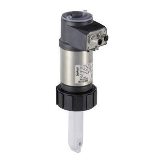
 Цифровой преобразователь электропроводности (кондуктометр) Burkert 8222. Преобразователь 8202 имеет 1 или 2 аналоговых выходных сигнала для значения рН и температуры. Кондуктометр Burkert 8222 поставляется для трех диапазонов измерения: К=0,01, К=0,1, К=1. Простой монтаж в трубопровод осуществляется благодаря накидной гайке от стандартной разъемной муфты из ПВХ или ПВДФ. Универсальный съемный дисплей позволяет использовать 1 дисплей для настройки нескольких датчиков 8222, а также программировать датчик рН 8202. Для монтажа в трубопровод рекомендуется использовать специальный адаптер S022 или ответные части разъемной муфты с соответстующим тройником.
Технические данные![]()
производитель
Burkert
Если вы хотите купить цифровой преобразователь электропроводности burkert 8222 , вы можете:
Ещё из раздела Аналитические датчики

Индуктивный датчик проводимости Indumax CLS54D создан на основе технологии Memosens для гигиенических и стерильных сред. Датчик CLS54D соответствует самым строгим требованиям по гигиене и стерильности. Его великолепная производительность и …

Цифровой нестеклянный датчик Tophit CPS471D используется в пищевой и фармацевтической промышленности для гигиенических процессов. Датчик может обрабатываться в автоклаве и имеет небьющийся корпус PEEK, гарантирует максимальную безопасность при …

Кондуктивный датчик Condumax CLS21 производства Endress+Hauser позволяет надежно измерить электропроводностьво всех технологических процессах и при любых условиях окружающей среды. Датчик обеспечивает точность и надежность измеряемых значений, что …

Компактный электрод для сточных вод и процессов флотации Orbipac CPF82 – это простой аналоговый вариант для измерения ОВП в агрессивных средах. Низкие трудозатраты на техобслуживание обеспечивается его грязеотталкивающей диафрагмой из PTFE. Электрод …

Стеклянный электрод Memosens для пищевой и фармацевтической промышленности Ceragel CPS71D – это цифровой датчик, который предназначен для стерильных и гигиенических процессов. Датчик Ceragel CPS71D обладает стабиальностью измерений даже в средах с …

Стеклянный электрод Memosens CPS31D применяется в питьевой воде и воде в плавательных бассейнах. Он является цифровым индикатором для компенсации pH в рамках процессов дезинфекции. Присутствие трех диафрагм гарантирует его пригодность в условиях …

Датчик Tophit CPS491 предназначен для работы в средах с высокой вязкостью в химических процессах, производстве бумаги или красителей, а также для сильно загрязненных или волокнистых сред, суспензий, эмульсий или отложений. Благодаря неразбиваемому …

Датчик мутности Turbimax CUS31 применяется для измерения мутности и содержания взвешенных веществ в воде. Измеритель Turbimax CUS31 представляет собой монтируемый и погружаемый датчик для питьевой и технологической воды, использует метод рассеянного …

Технологический погружаемый датчик измерения мутности Turbimax CUS41 позволяет измерять мутность и содержание взвешенных веществ в технической и сточной воде. Для исследования используется мультиканальная технология и метод 90° рассеянного света. …

Датчик растворенного кислорода Oxymax COS41 является благонадежным и точным датчиком для систем водоснабжения , в том числе сточных вод. Основные преимущества: Высокая точность измерения. Продолжительные интервалы регламентного техобслуживания. …

Цифровой преобразователь рН Burkert 8202 с возможностью подключения электродов любого производителя. Преобразователь 8202 имеет 1 или 2 аналоговых выходных сигнала для значения рН и температуры. Основное преимущество- простой монтаж в трубопровод …

Преобразователь рН Burkert 8205 с цифровой индикацией предназначен для измерения значения рН в диапазоне 0-14. Датчик рН 8205 имеет аналоговый и релейный выходные сигналы. Монтаж в трубопровод осуществляется при помощи фитингов S020/1501 Технические …