- Manuals
- Brands
- Burkert Manuals
- Valve Positioners
- 8694
Manuals and User Guides for Burkert 8694. We have 4 Burkert 8694 manuals available for free PDF download: Operating Instructions Manual, Quick Start Manual
Burkert 8694 Operating Instructions Manual (244 pages)
Positioner TopControl Basic
Electropneumatic position controller
Brand: Burkert
|
Category: Valve Positioners
|
Size: 3.68 MB
Table of Contents
-
English
3
-
Table of Contents
3
-
1 Operating Instructions
7
-
Symbols
7
-
Definition of Term / Abbreviation
7
-
-
2 Authorized Use
8
-
Restrictions
8
-
-
3 Basic Safety Instructions
9
-
4 General Information
10
-
Contact Address
10
-
Warranty
10
-
Trademarks
10
-
Information on the Internet
10
-
-
5 System Description
11
-
Intended Application Area
11
-
Function of the Positioner and Combination with Valve Types
11
-
Features of the Valve Types
12
-
Structure of the Positioner
13
-
Representation
13
-
Features
14
-
Function Diagram of the Positioner with Single-Acting Actuator
15
-
-
Type 8694 Positioner (Position Controller)
16
-
Schematic Representation of the Position Control Type 8694
16
-
Functions of the Position Controller Software
17
-
-
Interfaces of the Positioner
19
-
-
6 Technical Data
20
-
Conformity
20
-
Standards
20
-
Licenses
20
-
Operating Conditions
20
-
Mechanical Data
20
-
Pneumatic Data
21
-
Type Labels
21
-
Type Label Standard
21
-
UL Type Label
22
-
UL Additional Label
22
-
-
Electrical Data
22
-
Electrical Data Without Bus Control 24 V DC
22
-
Electrical Data with AS-Interface Bus Control
23
-
-
Factory Settings of the Positioner
24
-
-
7 Control and Display Elements
25
-
Operating Status
25
-
Control and Display Elements of the Positioner
25
-
Configuration of the Keys
27
-
Function of the DIP Switches
29
-
Display of the Leds
31
-
Error Messages
32
-
Error Messages in MANUAL and AUTOMATIC Operating Statuses
32
-
Error Messages While the X.TUNE Function Is Running
32
-
-
-
8 Installation
33
-
Safety Instructions
33
-
Installation of the Positioner Type 8694 on Process Valves of Series 2103, 2300 and 2301
33
-
Installing the Positioner Type 8694 on Process Valves Belonging to Series 26Xx and 27Xx
36
-
Rotating the Actuator Module
40
-
Rotating the Positioner for Process Valves Belonging to Series 26Xx and 27Xx
42
-
-
9 Pneumatic Installation
43
-
Manual Actuation of the Actuator Via Pilot Valves
44
-
Single-Acting Actuators (Control Function a and B)
44
-
-
-
10 Electrical Installation 24 V DC
46
-
Safety Instructions
46
-
Electrical Installation With Circular Plug-In Connector
46
-
Designation of the Contacts Type 8694
46
-
Connection of the Positioner Type 8694
47
-
-
Electrical Installation With Cable Gland
48
-
-
11 As-Interface Installation
51
-
AS-Interface Connection
51
-
Maximum Length Of The Bus Line
51
-
Technical Data For As-Interface Pcbs
51
-
Programming Data
52
-
Communication Sequence For The Version S-7.A.5 Profile
53
-
Led Status Display
54
-
Electrical Installation As-Interface
55
-
Safety Instructions
55
-
Connection with Circular Plug-In Connector M12 X 1, 4-Pole, Male
56
-
Connection with Multi-Pole Cable and Ribbon Cable Terminal
56
-
-
-
12 Start-Up
58
-
Safety Instructions
58
-
Specifying The Standard Settings
58
-
Running the Automatic Adjustment X.TUNE
58
-
-
-
13 Operation and Function
61
-
Basic Functions
61
-
Dir.CMD
62
-
Effective Direction of the Positioner Set-Point Value
62
-
-
Cutoff
63
-
Sealing Function for the Positioner
63
-
-
Charact
64
-
Select the Transfer Characteristic between Input Signal (Position Set-Point Value) and Stroke
64
-
-
INPUT — Enter the Input Signal
66
-
Reset
67
-
Reset to Factory Settings
67
-
-
X.tune
67
-
Automatic Adjustment of the Positioner to the Relevant Operating Conditions
67
-
-
-
Auxiliary Functions
68
-
Dir.actuator
68
-
Effective Direction of the Actuator
68
-
Type
68
-
-
SPLITRANGE — Signal Split Range
69
-
X.limit
70
-
Limiting the Mechanical Stroke Range
70
-
-
X.time
71
-
Limiting the Control Speed
71
-
-
X.control
72
-
Parameterization of the Positioner
72
-
-
SAFE.POSITION — Definition of the Safe Position
72
-
Signal.error
73
-
Configuration of Signal Level Fault Detection
73
-
-
BINARY.INPUT — Activation of the Binary Input
73
-
OUTPUT (Optional)
74
-
Configuration of the Analog Output
74
-
-
-
-
14 Safety End Positions
75
-
Safety End Positions After Failure Of The Electrical Or Pneumatic Auxiliary Power
75
-
-
15 Maintenance
76
-
Safety Instructions
76
-
Service At The Air Intake Filter
77
-
-
16 Accessories
78
-
Communications Software
78
-
USB Interface
78
-
Download
78
-
-
-
17 Disassembly
79
-
Safety Instructions
79
-
Disassembly The Positioner
79
-
-
18 Packaging and Transport
81
-
19 Storage
81
-
20 Disposal
81
-
-
Deutsch
83
-
1 Die Bedienungsanleitung
87
-
Darstellungsmittel
87
-
Begriffsdefinition / Abkürzung
87
-
-
2 Bestimmungsgemässe Verwendung
88
-
Beschränkungen
88
-
-
3 Grundlegende Sicherheitshinweise
89
-
4 Allgemeine Hinweise
90
-
Kontaktadresse
90
-
Gewährleistung
90
-
Warenzeichen
90
-
Informationen IM Internet
90
-
-
5 Systembeschreibung
91
-
Vorgesehener Einsatzbereich
91
-
Funktion des Positioners und Kombination mit Ventiltypen
91
-
Merkmale der Ventiltypen
92
-
Aufbau des Positioners
93
-
Darstellung
93
-
Merkmale
94
-
Funktionsschema des Positioners mit Einfachwirkendem Antrieb
95
-
-
Typ 8694 Positioner (Stellungsregler)
96
-
Schematische Darstellung der Stellungsregelung Typ 8694
96
-
Funktionen der Stellungsregler-Software
97
-
-
Schnittstellen des Positioners
99
-
-
6 Technische Daten
100
-
Konformität
100
-
Normen
100
-
Zulassungen
100
-
Betriebsbedingungen
100
-
Mechanische Daten
101
-
Pneumatische Daten
101
-
Typschilder
101
-
Typschild Standard
101
-
UL-Typschild
102
-
UL-Zusatzschild
102
-
-
Elektrische Daten
102
-
Elektrische Daten ohne Busansteuerung 24 V DC
102
-
Elektrische Daten mit Busansteuerung AS-Interface
103
-
-
Werkseinstellungen des Positioners
104
-
-
7 Bedien- und Anzeigeelemente
105
-
Betriebszustand
105
-
Belegung der Tasten
107
-
Funktion der DIP-Schalter
109
-
Anzeige der Leds
111
-
Fehlermeldungen
112
-
Fehlermeldungen in den Betriebszuständen HAND und AUTOMATIK
112
-
Fehlermeldungen bei der Durchführung der Funktion X.TUNE
112
-
-
-
8 Montage
113
-
Sicherheitshinweise
113
-
Montage des Positioners Typ 8694 an Prozessventile der Reihe 2103, 2300 und 2301
113
-
Montage des Positioners Typ 8694 an Prozessventile der Reihe 26Xx und 27Xx
116
-
Drehen des Antriebsmoduls
120
-
Drehen des Positioners bei Prozessventilen der Reihe 26Xx und 27Xx
122
-
-
9 Pneumatische Installation
123
-
Manuelles Betätigen des Antriebs über Steuerventile
124
-
Einfachwirkende Antriebe (Steuerfunktion a und B)
124
-
-
-
10 Elektrische Installation 24 V DC
126
-
Sicherheitshinweise
126
-
Elektrische Installation Mit Rundsteckverbinder
126
-
Bezeichnung der Kontakte Typ 8694
126
-
Anschluss des Positioners Typ 8694
127
-
-
Elektrische Installation Mit Kabelverschraubung
128
-
-
11 As-Interface-Installation
131
-
AS-Interface-Anschaltung
131
-
Maximale Länge Der Bus-Leitung
131
-
Technische Daten Für As-Interface-Platinen
131
-
Programmierdaten
132
-
Ablauf Der Kommunikation Bei Der Version Profil S-7.A.5
133
-
LED-Zustandsanzeige As-Interface
134
-
Elektrische Installation As-Interface
135
-
Sicherheitshinweise
135
-
Anschluss mit Rundsteckverbinder M12 X 1, 4-Polig, Male
136
-
Anschluss mit Multipolkabel und Flachkabelklemme
136
-
-
-
12 Inbetriebnahme
138
-
Sicherheitshinweise
138
-
Festlegen Der Grundeinstellungen
138
-
Ausführen der Automatischen Anpassung X.TUNE
138
-
-
-
13 Bedienung und Funktion
141
-
Grundfunktionen
141
-
Dir.CMD
142
-
Wirkrichtung (Direction) des Positioner Sollwerts
142
-
-
Cutoff
143
-
Dichtschließfunktion für den Positioner
143
-
-
Charact
144
-
Übertragungskennlinie zwischen Eingangssignal (Stellungs-Sollwert) und Hub
144
-
-
Input
146
-
Eingabe des Eingangssignals
146
-
-
RESET./.FACTORY.RESET — Rücksetzen auf die Werkseinstellungen
147
-
X.tune
147
-
Automatische Anpassung des Positioners an die Jeweiligen Betriebsbedingungen
147
-
-
-
Zusatzfunktionen
148
-
Dir.actuator
148
-
Wirkrichtung (Direction) des Stellantriebs
148
-
-
Splitrange
149
-
Signalbereichsaufteilung (Split Range)
149
-
-
X.limit
150
-
Begrenzung des Mechanischen Hubbereichs
150
-
-
X.time
151
-
Begrenzung der Stellgeschwindigkeit
151
-
-
X.control
152
-
Parametrierung des Positioners
152
-
-
SAFE.POSITION — Definition der Sicherheitsstellung
152
-
Signal.error
153
-
Konfiguration Fehlererkennung Signalpegel
153
-
-
BINARY.INPUT — Aktivierung des Digitaleingangs
153
-
OUTPUT (Option)
154
-
Konfiguration des Analogen Ausgangs
154
-
-
-
-
14 Sicherheitsendlagen
155
-
Sicherheitsendlagen Nach Ausfall Der Elektrischen Bzw. Pneumatischen Hilfsenergie
155
-
-
15 Wartung
156
-
Sicherheitshinweise
156
-
Service Am Zuluftfilter
157
-
-
16 Zubehör
158
-
Kommunikation-Software
158
-
USB-Schnittstelle
158
-
Download
158
-
-
-
17 Demontage
159
-
Sicherheitshinweise
159
-
Demontage Positioner
159
-
-
18 Verpackung, Transport
161
-
19 Lagerung
161
-
20 Entsorgung
161
-
-
Français
163
-
1 Propos de Ce Manuel
167
-
Symboles
167
-
Définition du Terme / Abréviation
167
-
-
2 Utilisation Conforme
168
-
Restrictions
168
-
-
3 Consignes de Sécurité Fondamentales
169
-
4 Indications Générales
170
-
Adresse
170
-
Garantie Légale
170
-
Marques Déposées
170
-
Informations Sur Internet
170
-
-
5 Description du Système
171
-
Utilisation Prévue
171
-
Fonction du Positionneur Et Association Avec Les Types de Vanne
171
-
Caractéristiques des Types de Vanne
172
-
Structure du Positionneur
173
-
Représentation
173
-
Caractéristiques
174
-
Schéma Fonctionnel du Positionneur Avec Actionneur À Simple Effet
175
-
-
Positionneur Type 8694 (Régulateur de Position)
176
-
Fonctions du Logiciel du Régulateur de Position
177
-
-
Interfaces du Positionneur
179
-
-
6 Caractéristiques Techniques
180
-
Conformité
180
-
Normes
180
-
Homologations
180
-
Conditions D’exploitation
180
-
Caractéristiques Mécaniques
180
-
Caractéristiques Pneumatiques
181
-
Plaques Signalétiques
181
-
Plaque Signalétique Standard
181
-
Plaque Signalétique UL
182
-
Plaque Supplémentaire UL
182
-
-
Caractéristiques Électriques
182
-
Caractéristiques Électriques Sans Commande Bus 24 V DC
182
-
Caractéristiques Électriques Avec Commande Bus Interface as
183
-
-
Réglages Usine du Positionneur
184
-
Fonction des Interrupteurs DIP
189
-
Affichage des LED
191
-
Messages D’erreur
192
-
Messages D’erreur Dans Les États de Marche MANUEL Et AUTOMATIQUE
192
-
Messages D’erreur Lors de L’exécution de la Fonction X.TUNE
192
-
-
-
8 Montage
193
-
Consignes de Sécurité
193
-
Montage du Positionneur Type 8694 Sur Les Vannes Process des Séries 2103, 2300 Et 2301
193
-
Montage du Positionneur Type 8694 Sur Les Vannes Process des Séries 26Xx Et 27Xx
196
-
Rotation du Module Actionneur
200
-
Rotation du Positionneur Pour Les Vannes Process des Séries 26Xx Et 27Xx
202
-
-
9 Installation Pneumatique
203
-
Commande Manuelle de L’actionneur Via Vannes Pilotes
204
-
Actionneurs Simple Effet (Fonction a Et B)
204
-
-
-
10 Installation Électrique 24 V DC
206
-
Consignes De Sécurité
206
-
Installation Électrique Avec Connecteur Rond
206
-
Désignation des Contacts Type 8694
206
-
Raccordement du Positionneur Type 8694
207
-
-
Installation Électrique Avec Presse-Étoupe
208
-
-
11 Interface as — Installation
211
-
Connexion Interface As
211
-
Longueur Maximale Du Circuit Bus
211
-
Caractéristiques Techniques Pour Circuits Imprimés Interface As
211
-
Données De Programmation
212
-
Affichage D’état Led
214
-
Installation Électrique Interface As
215
-
Consignes de Sécurité
215
-
Raccordement Avec Connecteur Rond M12 X 1, 4 Pôles, Mâle
216
-
Raccordement Avec Câble Multipolaire Et Borne À Câble Plat
216
-
-
-
12 Mise en Service
218
-
Consignes De Sécurité
218
-
Détermination Des Réglages De Base
218
-
Exécution de L’adaptation Automatique X.TUNE
218
-
-
-
13 Commande Et Fonctionnement
221
-
Fonctions De Base
221
-
Dir.CMD
222
-
Sens D’action (Direction) de la Valeur de Consigne du Positionneur
222
-
-
Cutoff
223
-
Fonction de Fermeture Étanche du Positionneur
223
-
-
Charact
224
-
Caractéristique de Transfert entre Le Signal D’entrée (Valeur de Consigne de Position) Et la Course
224
-
-
INPUT — Saisie du Signal D’entrée
226
-
Reset
227
-
Rétablissement des Réglages Usine
227
-
Adaptation Automatique du Positionneur Aux Conditions D’exploitation Actuelles
227
-
-
-
Fonctions Supplémentaires
228
-
DIR.ACTUATOR — Sens D’action (Direction) de L’actionneur
228
-
Splitrange
229
-
Répartition de la Plage du Signal (Split Range)
229
-
Limitation de la Course Mécanique
230
-
Limitation de la Vitesse de Réglage
231
-
-
X.CONTROL — Paramétrage du Positionneur
232
-
SAFE.POSITION — Définition de la Position de Sécurité
232
-
Signal.error
233
-
Configuration Détection de Défaut du Niveau du Signal
233
-
-
BINARY.INPUT — Activation de L’entrée Binaire
233
-
OUTPUT (Option)
234
-
Configuration de la Sortie Analogique
234
-
-
-
-
14 Positions Finales de Sécurité
235
-
Positions Finales de Sécurité Après Une Panne D’énergie Auxiliaire Électrique Ou Pneumatique
235
-
-
15 Maintenance
236
-
Consignes De Sécurité
236
-
Service Sur Le Filtre D’amenée D’air
237
-
-
16 Accessoires
238
-
Logiciel De Communication
238
-
Interface USB
238
-
Téléchargement
238
-
-
-
17 Démontage
239
-
Consignes De Sécurité
239
-
Démontage Du Positionneur
239
-
-
18 Emballage, Transport
241
-
19 Stockage
241
-
20 Élimination
241
-
Advertisement

Burkert 8694 Operating Instructions Manual (196 pages)
Positioner TopControl Basic.
Electropneumatic position controller
Brand: Burkert
|
Category: Valve Positioners
|
Size: 7.47 MB
Table of Contents
-
English
3
-
Table of Contents
3
-
1 Operating Instructions
7
-
Symbols
7
-
-
2 Authorized Use
8
-
Restrictions
8
-
-
3 Basic Safety Instructions
9
-
4 General Information
10
-
Contact Address
10
-
Warranty
10
-
Trademarks
10
-
Information On The Internet
10
-
-
5 System Description
11
-
Intended Application Area
11
-
Function Of The Positioner And Combination With Valve Types
11
-
Features Of The Valve Types
12
-
Structure Of The Positioner
13
-
Representation
13
-
Features
14
-
Function Diagram of the Positioner with Single-Acting Actuator
15
-
-
Type 8694 Positioner (Position Controller)
16
-
Schematic Representation of the Position Control Type 8694
16
-
Functions of the Position Controller Software
17
-
-
Interfaces Of The Positioner
19
-
-
6 Technical Data
20
-
Conformity
20
-
Standards
20
-
Operating Conditions
20
-
Mechanical Data
20
-
Pneumatic Data
21
-
Type Label
21
-
Electrical Data
22
-
Electrical Data Without Bus Control 24 V DC
22
-
Electrical Data with AS-Interface Bus Control
22
-
-
Factory Settings Of The Positioner
23
-
-
7 Control and Display Elements
24
-
Operating Status
24
-
Control And Display Elements Of The Positioner
24
-
Configuration Of The Keys
26
-
Function Of The Dip Switches
28
-
Display Of The Leds
30
-
Error Messages
31
-
Error Messages in MANUAL and AUTOMATIC Operating Statuses
31
-
Error Messages While the X.TUNE Function Is Running
31
-
-
-
8 Installation
32
-
Safety Instructions
32
-
Installation of the Positioner Type 8694 on Process Valves of Series 2103, 2300 and 2301
32
-
Installing the Positioner Type 8694 on Process Valves Belonging to Series 26Xx and 27Xx
35
-
Rotating The Actuator Module
39
-
Rotating the Positioner for Process Valves Belonging to Series 26Xx and 27Xx
41
-
-
9 Fluid Installation
42
-
Safety Instructions
42
-
Installing The Process Valve
42
-
Pneumatic Connection Of The Positioner
43
-
-
10 Electrical Installation 24 V DC
44
-
Safety Instructions
44
-
Electrical Installation With Circular Plug-In Connector
44
-
Designation of the Contacts Type 8694
44
-
Type
44
-
Connection of the Positioner Type 8694
45
-
-
Electrical Installation With Cable Gland
46
-
Designation of the Screw-Type Terminals
46
-
Connection of the Positioner Type 8694
46
-
-
-
11 As-Interface Installation
48
-
As-Interface Connection
48
-
Technical Data For As-Interface Pcbs
48
-
Programming Data
48
-
Communication Sequence For The Version S-7.A.5 Profile
49
-
Led Status Display
50
-
Electrical Installation As-Interface
51
-
Safety Instructions
51
-
Connection with Circular Plug-In Connector M12 X 1, 4-Pole, Male
51
-
Connection with Multi-Pole Cable and Ribbon Cable Terminal
52
-
-
-
12 Start-Up
53
-
Safety Instructions
53
-
Specifying The Standard Settings
53
-
Running the Automatic Adjustment X.TUNE
53
-
-
-
13 Operation and Function
55
-
Basic Functions
55
-
DIR.CMD — Effective Direction of the Positioner Set-Point Value
56
-
CUTOFF — Sealing Function for the Positioner
57
-
CHARACT — Select the Transfer Characteristic between Input Signal
58
-
(Position Set-Point Value) and Stroke
58
-
-
Auxiliary Functions
59
-
-
14 Safety Positions
60
-
Safety Positions After Failure Of The Electrical Or Pneumatic Auxiliary Power
60
-
-
15 Maintenance
61
-
Safety Instructions
61
-
Service At The Air Intake Filter
62
-
-
16 Accessories
63
-
Communications Software (Pc Software Based On Fdt/Dtm Technology)
63
-
Pactware 3.6
63
-
USB Interface
63
-
Download
63
-
-
-
17 Disassembly
64
-
Safety Instructions
64
-
Disassembly The Positioner
64
-
-
18 Packaging and Transport
66
-
19 Storage
66
-
20 Disposal
66
-
-
Deutsch
67
-
1 Die Bedienungsanleitung
71
-
Darstellungsmittel
71
-
-
2 Bestimmungsgemässe Verwendung
72
-
Beschränkungen
72
-
Vorhersehbarer Fehlgebrauch
72
-
-
3 Grundlegende Sicherheitshinweise
73
-
4 Allgemeine Hinweise
74
-
Kontaktadresse
74
-
Gewährleistung
74
-
Warenzeichen
74
-
Informationen IM Internet
74
-
-
5 Systembeschreibung
75
-
Vorgesehener Einsatzbereich
75
-
Funktion Des Positioners Und Kombination Mit Ventiltypen
75
-
Merkmale Der Ventiltypen
76
-
Aufbau Des Positioners
77
-
Darstellung
77
-
Merkmale
78
-
Funktionsschema des Positioners mit Einfachwirkendem Antrieb
79
-
-
Typ 8694 Positioner (Stellungsregler)
80
-
Schematische Darstellung der Stellungsregelung Typ 8694
80
-
Funktionen der Stellungsregler-Software
81
-
-
Schnittstellen Des Positioners
83
-
-
6 Technische Daten
84
-
Konformität
84
-
Normen
84
-
Betriebsbedingungen
84
-
Mechanische Daten
84
-
Pneumatische Daten
85
-
Typschild
85
-
Elektrische Daten
86
-
Elektrische Daten ohne Busansteuerung 24 V DC
86
-
Elektrische Daten mit Busansteuerung AS-Interface
86
-
-
Werkseinstellungen Des Positioners
87
-
-
7 Bedien- und Anzeigeelemente
88
-
Betriebszustand
88
-
Bedien- Und Anzeigeelemente Des Positioners
88
-
Belegung Der Tasten
90
-
Funktion Der Dip-Schalter
92
-
Anzeige Der Leds
94
-
Fehlermeldungen
95
-
Fehlermeldungen in den Betriebszuständen HAND und AUTOMATIK
95
-
Fehlermeldungen bei der Durchführung der Funktion X.TUNE
95
-
-
-
8 Montage
96
-
Sicherheitshinweise
96
-
Montage des Positioners Typ 8694 an Prozessventile der Reihe 2103, 2300 und 2301
96
-
Montage des Positioners Typ 8694 an Prozessventile der Reihe 26Xx und 27Xx
99
-
Drehen Des Antriebsmoduls
103
-
Drehen des Positioners bei Prozessventilen der Reihe 26Xx und 27Xx
105
-
-
9 Fluidische Installation
106
-
Sicherheitshinweise
106
-
Installation Des Prozessventils
106
-
Pneumatischer Anschluss Des Positioners
107
-
-
10 Elektrische Installation 24 V DC
108
-
Sicherheitshinweise
108
-
Elektrische Installation Mit Rundsteckverbinder
108
-
Bezeichnung der Kontakte Typ 8694
108
-
Anschluss des Positioners Typ 8694
109
-
-
Elektrische Installation Mit Kabelverschraubung
110
-
Bezeichnung der Schraubklemmen
110
-
Anschluss des Positioners Typ 8694
110
-
-
-
11 As-Interface-Installation
112
-
As-Interface-Anschaltung
112
-
Technische Daten Für As-Interface-Platinen
112
-
Programmierdaten
112
-
Ablauf Der Kommunikation Bei Der Version Profil S-7.A.5
113
-
Led Zustandsanzeige As-Interface
114
-
Elektrische Installation As-Interface
115
-
Sicherheitshinweise
115
-
Anschluss mit Rundsteckverbinder M12 X 1, 4-Polig, Male
115
-
Anschluss mit Multipolkabel und Flachkabelklemme
116
-
-
-
12 Inbetriebnahme
117
-
Sicherheitshinweise
117
-
Festlegen Der Grundeinstellungen
117
-
Ausführen der Automatischen Anpassung X.TUNE
117
-
-
-
13 Bedienung und Funktion
119
-
Grundfunktionen
119
-
Dir.CMD
120
-
Wirkrichtung (Direction) des Positioner Sollwerts
120
-
-
Cutoff
121
-
Dichtschließfunktion für den Positioner
121
-
-
Charact
122
-
Übertragungskennlinie zwischen Eingangssignal (Stellungs-Sollwert) und Hub
122
-
-
-
Zusatzfunktionen
123
-
-
14 Sicherheitsstellungen
124
-
Sicherheitsstellungen Nach Ausfall Der Elektrischen Bzw. Pneumatischen Hilfsenergie
124
-
-
15 Wartung
125
-
Sicherheitshinweise
125
-
Service Am Zuluftfilter
126
-
-
16 Zubehör
127
-
Kommunikationssoftware (Pc-Software Auf Fdt/Dtm Technologie)
127
-
Pactware 3.6
127
-
USB Schnittstelle
127
-
Download
127
-
-
-
17 Demontage
128
-
Sicherheitshinweise
128
-
Demontage Positioner
128
-
-
18 Verpackung, Transport
130
-
19 Lagerung
130
-
20 Entsorgung
130
-
-
Français
131
-
1 A Propos de Ce Manuel
135
-
Symboles
135
-
-
2 Utilisation Conforme
136
-
Restrictions
136
-
-
3 Consignes de Sécurité Fondamentales
137
-
4 Indications Générales
138
-
Adresse
138
-
Garantie Légale
138
-
Marques Déposées
138
-
Informations Sur Internet
138
-
-
5 Description du Système
139
-
Utilisation Prévue
139
-
Fonction Du Positionneur Et Association Avec Les Types De Vanne
139
-
Caractéristiques Des Types De Vanne
140
-
Structure Du Positionneur
141
-
Représentation
141
-
Caractéristiques
142
-
Schéma Fonctionnel du Positionneur Avec Actionneur À Simple Effet
143
-
-
Positionneur Type 8694 (Régulateur De Position)
144
-
Représentation Schématique de la Régulation de Position du Type 8694
144
-
Fonctions du Logiciel du Régulateur de Position
145
-
-
Interfaces Du Positionneur
147
-
-
6 Caractéristiques Techniques
148
-
Conformité
148
-
Normes
148
-
Conditions D’exploitation
148
-
Caractéristiques Mécaniques
148
-
Caractéristiques Pneumatiques
149
-
Description De L’étiquette
149
-
Caractéristiques Électriques
150
-
Caractéristiques Électriques Sans Commande Bus 24 V DC
150
-
Caractéristiques Électriques Avec Commande Bus Interface as
150
-
-
Réglages Usine Du Positionneur
151
-
-
7 Eléments de Commande Et D’affichage
152
-
Etat De Marche
152
-
Eléments De Commande Et D’affichage Du Positionneur
152
-
Affectation Des Touches
154
-
Fonction Des Interrupteurs Dip
156
-
Affichage Des Led
158
-
Messages D’erreur
159
-
Messages D’erreur Dans Les États de Marche MANUEL Et AUTOMATIQUE
159
-
Messages D’erreur Lors de L’exécution de la Fonction X.TUNE
159
-
-
-
8 Montage
160
-
Consignes De Sécurité
160
-
Montage du Positionneur Type 8694 Sur Les Vannes Process des Séries 2103, 2300 Et 2301
160
-
Montage du Positionneur Type 8694 Sur Les Vannes Process des Séries 26Xx Et 27Xx
163
-
Rotation Du Module Actionneur
167
-
Rotation du Positionneur Pour Les Vannes Process des Séries 26Xx Et 27Xx
169
-
-
9 Installation Fluidique
170
-
Consignes De Sécurité
170
-
Installation De La Vanne Process
170
-
Raccordement Pneumatique Du Positionneur
171
-
-
10 Installation Électrique 24 V DC
172
-
Consignes De Sécurité
172
-
Installation Électrique Avec Connecteur Rond
172
-
Désignation des Contacts Type 8694
172
-
Raccordement du Positionneur Type 8694
173
-
-
Installation Électrique Avec Presse-Étoupe
174
-
Désignation des Bornes Vissées
174
-
Raccordement du Positionneur Type 8694
174
-
-
-
11 Interface as — Installation
176
-
Connexion Interface As
176
-
Caractéristiques Techniques Pour Circuits Imprimés Interface As
176
-
Données De Programmation
176
-
Déroulement De La Communication Avec La Version Profil S-7.A.5
177
-
Affichage D’état Led
178
-
Installation Électrique Interface As
179
-
Consignes de Sécurité
179
-
Raccordement Avec Connecteur Rond M12 X 1, 4 Pôles, Mâle
179
-
Raccordement Avec Câble Multipolaire Et Borne À Câble Plat
180
-
-
-
12 Mise en Service
181
-
Consignes De Sécurité
181
-
Détermination Des Réglages De Base
181
-
Exécution de L’adaptation Automatique X.TUNE
181
-
-
-
13 Commande Et Fonctionnement
183
-
Fonctions De Base
183
-
Dir.CMD
184
-
Sens D’action (Direction) de la Valeur de Consigne du Positionneur
184
-
-
Cutoff
185
-
Fonction de Fermeture Étanche du Positionneur
185
-
-
Charact
186
-
Caractéristique de Transfert entre Le Signal D’entrée
186
-
(Valeur de Consigne de Position) Et la Course
186
-
-
-
Fonctions Supplémentaires
187
-
-
14 Positions de Sécurité
188
-
Positions De Sécurité Après Une Panne D’énergie Auxiliaire Électrique Ou Pneumatique
188
-
-
15 Maintenance
189
-
Consignes De Sécurité
189
-
Service Sur Le Filtre D’amenée D’air
190
-
-
16 Accessoires
191
-
Logiciel De Communication (Logiciel Pc Sur Technologie Fdt/Dtm)
191
-
Pactware 3.6
191
-
Interface USB
191
-
Téléchargement
191
-
-
-
17 Démontage
192
-
Consignes De Sécurité
192
-
Démontage Du Positionneur
192
-
-
18 Emballage, Transport
194
-
19 Stockage
194
-
20 Elimination
194
-
Burkert 8694 Operating Instructions Manual (87 pages)
Positioner Top Control Basic
Brand: Burkert
|
Category: Valve Positioners
|
Size: 2.78 MB
Table of Contents
-
Table of Contents
3
-
1 About These Instructions
7
-
Symbols
7
-
Definition of Terms
8
-
Firmware Changes
8
-
-
2 Intended Use
9
-
3 Basic Safety Instructions
10
-
4 General Information
11
-
Contact Address
11
-
Warranty
11
-
Trademarks
11
-
Information on the Internet
11
-
-
5 System Description
12
-
Intended Application Area
12
-
Function of the Positioner and Combination with Valve Types
12
-
Features of the Valve Types
13
-
Structure of the Positioner
14
-
Representation
14
-
Features
15
-
Function Diagram of the Positioner with Single-Acting Actuator
16
-
-
Type 8694 Positioner (Position Controller)
17
-
Schematic Representation of the Position Control Type 8694
17
-
Functions of the Position Controller Software
18
-
-
Interfaces of the Positioner
20
-
-
6 Technical Data
21
-
Conformity
21
-
Standards
21
-
Licenses
21
-
Operating Conditions
21
-
Mechanical Data
21
-
Pneumatic Data
22
-
Type Labels
22
-
Type Label
22
-
UL Additional Label
22
-
-
Electrical Data
23
-
Electrical Data, Without Fieldbus Communication
23
-
Electrical Data, IO-Link
24
-
Electrical Data, Büs
24
-
-
Factory Settings of the Positioner
25
-
-
7 Control and Display Elements
26
-
Operating State
26
-
Control and Display Elements of the Positioner
26
-
Configuration of the Buttons
28
-
Function of the DIP Switches
30
-
Display of the Leds
32
-
Device Status Display
32
-
Status LED, Green
34
-
-
Error Messages
35
-
Messages for Device Status „Out of Specification
35
-
Messages: Actuator Moves to Safety Position
35
-
-
-
8 Installation
37
-
Safety Instructions
37
-
Installation of the Positioner Type 8694 on Process Valves of Series 2103, 2300 and 2301
37
-
Installing the Positioner Type 8694 on Process Valves Belonging to Series 26Xx and 27Xx
40
-
Rotating the Actuator Module
44
-
Rotating the Positioner for Process Valves Belonging to Series 26Xx and 27Xx
46
-
-
9 Pneumatic Installation
47
-
Safety Instructions
47
-
Connecting the Device Pneumatically
47
-
Manual Actuation of the Actuator Via Pilot Valves
48
-
Single-Acting Actuators (Control Function a and B)
48
-
-
-
10 Electrical Installation 24 V DC
50
-
Safety Instructions
50
-
Electrical Installation With Circular Plug-In Connector
50
-
Designation of the Contacts Type 8694
50
-
Connection of the Positioner Type 8694
51
-
-
Electrical Installation With Cable Gland
53
-
-
11 Electrical Installation, Io-Link
56
-
12 Electrical Installation, Büs
57
-
13 Start-Up
58
-
Safety Instructions
58
-
Specifying The Standard Settings
58
-
Running the Automatic Adjustment X.TUNE
58
-
-
Setting With Bürkert Communicator
60
-
Connecting IO-Link Device with Bürkert Communicator
60
-
Connecting Büs Device with Bürkert Communicator
61
-
-
-
14 Io-Link
62
-
Information, Io-Link
62
-
Technical Specifications, Io-Link
62
-
Configuration of the Fieldbus
62
-
-
-
15 Büs
63
-
Information, Büs
63
-
Configuration Of The Fieldbus
63
-
-
16 Operation and Function
64
-
Basic Functions
64
-
Dir.CMD
65
-
Reversal Of The Effective Direction Of The Positioner Set-Point Value
65
-
-
Cutoff
66
-
Sealing Function for the Positioner
66
-
-
Charact
67
-
Characteristic Correction between Input Signal (Position Set-Point Value) and Stroke
67
-
-
Input
69
-
Enter the Standard Signal
69
-
-
Reset
70
-
Reset to Factory Settings
70
-
-
X.tune
70
-
Automatic Calibration of the Position Controller
70
-
-
-
Auxiliary Functions
71
-
Dir.act
72
-
Reversal Of The Effective Direction Of The Actuator
72
-
-
Spltrng
73
-
Signal Split Range
73
-
-
X.LIMIT — Stroke Limit
74
-
X.time
75
-
Limit Actuating Time
75
-
-
X.control
76
-
Control Parameters of the Positioner
76
-
-
Safpos
76
-
Definition Of The Safe Position
76
-
-
Sig.error
77
-
Configuration of Cable Break Detection (Only for Variant Without Fieldbus Communication)
77
-
-
BINARY.IN (Variant)
77
-
Configuration Of The Digital Input (Only For Variant Without Fieldbus Communication)
77
-
-
OUTPUT (Variant)
78
-
Configuration of the Analog Output (Only for Variant Without Fieldbus Communication)
78
-
-
16.2.10 Setting the LED Mode, Device Status
78
-
-
-
17 Safety End Positions
79
-
Safety End Positions After Failure Of The Electrical Or Pneumatic Auxiliary Power
79
-
-
18 Maintenance
80
-
Safety Instructions
80
-
Service At The Air Intake Filter
81
-
-
19 Accessories
82
-
Communications Software
82
-
-
20 Disassembly
83
-
Safety Instructions
83
-
Disassembly The Positioner
83
-
Advertisement

Burkert 8694 Quick Start Manual (76 pages)
Positioner TopControl Basic
Brand: Burkert
|
Category: Accessories
|
Size: 2.34 MB
Table of Contents
-
English
3
-
Table of Contents
3
-
Symbols
4
-
Quickstart
4
-
Definition of Term «Device
4
-
Authorized Use
5
-
Basic Safety Instructions
5
-
Restrictions
5
-
General Information
7
-
Structure And Function
7
-
Contact Address
7
-
Warranty
7
-
Information on the Internet
7
-
Technical Data
8
-
Conformity
8
-
Standards
8
-
Operating Conditions
8
-
Mechanical Data
9
-
Type Label
9
-
Pneumatic Data
9
-
Electrical Data
10
-
Installation
11
-
Factory Settings of the Positioner
11
-
Safety Instructions
11
-
Installing the Positioner on Process Valves Belonging to Series 2103 and 23Xx
12
-
Installing the Positioner on Process Valves Belonging to Series 26Xx and 27Xx
13
-
Fluid Installation
15
-
Safety Instructions
15
-
Installing the Process Valve
15
-
Pneumatic Connection of the Positioner
15
-
Electrical Installation
16
-
Safety Instructions
16
-
Electrical Installation 24 V DC
16
-
Electrical Installation as Interface
18
-
Start-Up
19
-
Safety Instructions
19
-
Automatic Adjustment X.TUNE
19
-
Control and Display Elements
21
-
Safety Positions
24
-
Accessories
25
-
Packaging, Transport, Storage
25
-
-
Deutsch
27
-
Begriffsdefinition Gerät
28
-
Darstellungsmittel
28
-
Der Quickstart
28
-
Beschränkungen
29
-
Bestimmungsgemässe Verwendung
29
-
Grundlegende Sicherheitshinweise
29
-
Allgemeine Hinweise
31
-
Aufbau Und Funktion
31
-
Gewährleistung
31
-
Informationen IM Internet
31
-
Kontaktadresse
31
-
Betriebsbedingungen
32
-
Konformität
32
-
Normen
32
-
Technische Daten
32
-
Mechanische Daten
33
-
Pneumatische Daten
33
-
Typschild
33
-
Elektrische Daten
34
-
Montage
35
-
Sicherheitshinweise
35
-
Werkseinstellungen des Positioners
35
-
Montage Positioner an Prozessventile der Reihe 2103, 2300 und 2301
36
-
Montage Positioner an Prozessventile der Reihe 26Xx und 27Xx
37
-
Fluidische Installation
39
-
Installation Prozessventil
39
-
Pneumatischer Anschluss des Positioners
39
-
Sicherheitshinweise
39
-
Elektrische Installation
40
-
Elektrische Installation 24 V DC
40
-
Sicherheitshinweise
40
-
Elektrische Installation AS-Interface
42
-
Automatische Anpassung (X.TUNE)
43
-
Inbetriebnahme
43
-
Sicherheitshinweise
43
-
Bedienung und Anzeigeelemente
45
-
Sicherheitsstellungen
48
-
Transport, Lagerung, Verpackung
49
-
Zubehör
49
-
-
Français
51
-
Définition du Terme « Appareil
52
-
Quickstart
52
-
Symboles
52
-
Consignes De Sécurité Fondamentales
53
-
Restrictions
53
-
Utilisation Conforme
53
-
Adresse
55
-
Garantie Légale
55
-
Indications Générales
55
-
Informations Sur Internet
55
-
Structure Et Mode De Fonctionnement
55
-
Caractéristiques Techniques
56
-
Conditions D’exploitation
56
-
Conformité
56
-
Normes
56
-
Caractéristiques Mécaniques
57
-
Caractéristiques Pneumatiques
57
-
Étiquette
57
-
Caractéristiques Électriques
58
-
Consignes de Sécurité
59
-
Montage
59
-
Réglages Usine du Positionneur
59
-
Montage du Positionneur Type 8694 Sur Les Vannes Process des Séries 2103 Et 23Xx
60
-
Montage du Positionneur Type 8694 Sur Les Vannes Process des Séries 26Xx Et 27Xx
61
-
Consignes de Sécurité
63
-
Installation Fluidique
63
-
Installation de la Vanne Process
63
-
Raccordement Pneumatique du Positionneur
63
-
Consignes de Sécurité
64
-
Installation Électrique
64
-
Installation Électrique 24 V DC
64
-
Installation Électrique Interface as
66
-
Adaptation Automatique X.TUNE
67
-
Consignes de Sécurité
67
-
Mise En Service
67
-
Eléments de Commande Et D’affichage
69
-
Accessoires
73
-
Positions De Sécurité
73
-
Emballage, Transport, Stockage
74
-
Advertisement
Related Products
-
burkert 8791 REV.2
-
Burkert TopControl Basic 8694 REV.2
-
Burkert 8791
-
Burkert 8690
-
Burkert 8691
-
Burkert 8692
-
Burkert 8693
-
Burkert 8697
-
Burkert 8691 REV.2
-
Burkert 8696 REV.2
Burkert Categories
Control Unit
Controller
Measuring Instruments
Transmitter
Accessories
More Burkert Manuals
-
Page 1
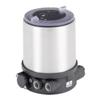
Type 8694 Positioner TopControl Basic Electropneumatic position controller Elektropneumatischer Stellungsregler Positionneur électropneumatique Operating Instructions Bedienungsanleitung Manuel d‘utilisation… -
Page 2
We reserve the right to make technical changes without notice. Technische Änderungen vorbehalten. Sous réserve de modifications techniques. © Bürkert Werke GmbH & Co. KG, 20 — 2017 Operating Instructions 1706/ _0080 / Original DE… -
Page 3: Table Of Contents
Features …………………………14 5.4.3 Function diagram of the positioner with single-acting actuator ……….15 Type 8694 positioner (position controller) ………………….16 5.5 5.5.1 Schematic representation of the position control Type 8694 ……….16 5.5.2 Functions of the position controller software …………….17 Interfaces of the positioner ……………………….19 5.6 TECHNICAL DATA ……………………………….20 6.1 Conformity ………………………………20…
-
Page 4
7.6.1 Error messages in MANUAL and AUTOMATIC operating statuses ………32 7.6.2 Error messages while the X.TUNE function is running …………..32 INSTALLATION ………………………………33 8.1 Safety instructions …………………………..33 8.2 Installation of the positioner Type 8694 on process valves of series 2103, 2300 and 2301 ..33 8.3 Installing the positioner Type 8694 on process valves belonging to series 26xx and 27xx ..36 8.4 Rotating the actuator module ……………………….40 8.5 Rotating the positioner for process valves belonging to series 26xx and 27xx …….42 PNEUMATIC INSTALLATION ………………………….43 Manual actuation of the actuator via pilot valves ………………..44 9.1… -
Page 5
Type 8694 10.2 Electrical installation with circular plug-in connector ………………46 10.2.1 Designation of the contacts Type 8694 ………………46 10.2.2 Connection of the positioner Type 8694 ………………47 10.3 Electrical installation with cable gland ……………………48 AS-INTERFACE INSTALLATION …………………………51 11.1 AS-Interface connection …………………………51 11.2 Maximum length of the bus line ……………………..51 11.3 Technical data for AS-Interface PCBs ……………………51 11.4 Programming data …………………………..52 11.5 Communication sequence for the version S-7.A.5 profile …………….53 11.6 LED status display …………………………..54 11.7 Electrical installation AS-interface ……………………..55… -
Page 6
Type 8694 13.2 Auxiliary functions ……………………………. 68 13.2.1. DIR.ACTUATOR — Effective direction of the actuator ………………..68 13.2.2. SPLITRANGE — Signal split range ……………………..69 13.2.3. X.LIMIT — Limiting the mechanical stroke range ………………..70 13.2.4. X.TIME — Limiting the control speed ……………………71 13.2.5. -
Page 7: Operating Instructions
▶ Designates an instruction to prevent risks. → Designates a procedure which you must carry out. 1.2 Definition of term / abbreviation The term “device” used in these instructions always stands for the positioner Type 8694. In these instructions, the abbreviation “Ex” always refers to “potentially explosive”. english…
-
Page 8: Authorized Use
▶ Correct transportation, correct storage and installation and careful use and maintenance are essential for reli- able and faultless operation. ▶ Use the positioner Type 8694 only as intended. 2.1 Restrictions If exporting the system/device, observe any existing restrictions.
-
Page 9: Basic Safety Instructions
General hazardous situations. To prevent injury, ensure: ▶ In the potentially explosion-risk area the positioner Type 8694 may be used only according to the specification on the separate approval sticker. For use observe the additional instructions enclosed with the device together with safety instructions for the explosion-risk area.
-
Page 10: General Information
And also on the Internet at: www.burkert.com 4.2 Warranty The warranty is only valid if the positioner Type 8694 is used as intended in accordance with the specified appli- cation conditions. 4.3 Trademarks Brands and trademarks listed below are trademarks of the corresponding companies / associations / organizations…
-
Page 11: System Description
Type 8694 Systemdescription SYSTEM DESCRIPTION 5.1 Intended application area The positioner Type 8694 is designed to be mounted on pneumatic actuators of process valves for the control of media. 5.2 Function of the positioner and combination with valve types Positioner Type 8694 is an electropneumatic position controller for pneumatically actuated control valves with single-acting actuators.
-
Page 12: Features Of The Valve Types
Type 8694 Systemdescription The position of the actuator is regulated according to the position set-point value. The position set-point value is specified by an external standard signal. Pneumatically actuated piston actuators and rotary actuators can be used as an actuator. Single-acting actuators are offered in combination with the positioner.
-
Page 13: Structure Of The Positioner
5.4 Structure of the positioner The positioner Type 8694 consists of the micro-processor controlled electronics, the position measuring system and the control system. The device is designed using three-wire technology. The positioner is operated via 2 keys and a 4-pole DIP switch. The pneumatic control system for single-acting actuators consists of 2 solenoid valves.
-
Page 14: Features
Type 8694 Systemdescription 5.4.2 Features • Models for single-acting valve actuators. • Position measuring system Contactless and therefore wear-free position measuring system. • Microprocessor-controlled electronics for signal processing, control and valve control. • Control module The device is controlled via 2 buttons and a 4-pole DIP switch. 2x 2-colored LEDs indicate different statuses of the device.
-
Page 15: Function Diagram Of The Positioner With Single-Acting Actuator
Type 8694 Systemdescription 5.4.3 Function diagram of the positioner with single-acting actuator The illustrated function diagram describes the function of the positioner (Type 8694). external position set-point value Position controller Actual Control system Positioner position 1: Aeration valve Control system 2: Bleed valve Pressure Position supply…
-
Page 16: Type 8694 Positioner (Position Controller)
Type 8694 Systemdescription 5.5 Type 8694 positioner (position controller) The position measuring system records the current position (POS) of the pneumatic actuator. The position controller compares this actual position value with the set-point value (CMD) which is definable as standard signal. In case of a control deviation (Xd1), a pulse-width modulated voltage signal is sent to the control system as a manipu- lated variable.
-
Page 17: Functions Of The Position Controller Software
Type 8694 Systemdescription 5.5.2 Functions of the position controller software Functions I • Activation via DIP switches • Parameter setting via communications software Additional function Effect Valve closes tight outside the control range. Specification Sealing function of the value (as %), from which the actuator is completely…
-
Page 18
Type 8694 Systemdescription Functions II • Activation and parameter setting via communications software Additional function Effect Standard signal for set-point value Select set-point value standard signal INPUT Effective direction of the actuator Assignment of the aeration status of the actuator chamber to the actual position. -
Page 19: Interfaces Of The Positioner
Figure 6: Interfaces The positioner Type 8694 is a 3-wire device, i.e. the power (24 V DC) is supplied separately from the set- point value signal. • Input for position set-point value (4 – 20 mA corresponds to 0 – 100 % (depending on position of DIP switch 1)).
-
Page 20: Technical Data
TECHNICAL DATA 6.1 Conformity In accordance with the EC Declaration of conformity, the positioner Type 8694 is compliant with the EC Directives. 6.2 Standards The applied standards on the basis of which compliance with the EC Directives is confirmed are listed in the EC type examination certificate and/or the EC Declaration of Conformity.
-
Page 21: Pneumatic Data
Socket connection G1/8 6.7 Type labels 6.7.1 Type label standard Example: Supply voltage / Control Control function — Pilot valve Type 8694 24 V DC Max. operating pressure single act Pilot 0,6 Pmax 7bar Max. ambient temperature Tamb 0°C — +60°C S/N 001000 00185134…
-
Page 22: Ul Type Label
Type 8694 Technicaldata 6.7.2 UL type label Example: Type; Features of the type code applicable to UL and ATEX Control function; pilot valve; Supply voltage pilot valve 8694 -E3-…-0 PU02 Single act Pilot 3.0 24V Max. operating pressure Pmax 7 bar Tamb -10 — +55 °C Max.
-
Page 23: Electrical Data With As-Interface Bus Control
Type 8694 Technicaldata Analogue position feedback max. load 560 Ω for current output 0/4 – 20 mA Binary input 0 – 5 V = log “0”, 12 — 30 V = log “1” inverted input in reverse order Communications interface Direct connection to PC via USB adapter with integrated interface driver, communication with communications software, see “Table 34: Accessories”.
-
Page 24: Factory Settings Of The Positioner
Type 8694 Technicaldata 6.9 Factory settings of the positioner Functions can be activated via DIP switches: Function Parameter Value CUTOFF Sealing function below Sealing function above 98 % CHARACT Select characteristic FREE DIR.CMD Effective direction set-point value rise Table 4: Factory settings — Functions I…
-
Page 25: Control And Display Elements
Type 8694 Controlanddisplayelements CONTROL AND DISPLAY ELEMENTS The following chapter describes the operating statuses as well as the control and display elements of the positioner. Further information on the operation of the positioner can be found in the chapter entitled “12 Start-up”. 7.1…
-
Page 26
Type 8694 Controlanddisplayelements The positioner features 2 buttons, 4-pole DIP switches and 2x 2-colored LEDs as a display element. NOTE! Breakage of the pneumatic connection pieces due to rotational impact. ▶ When unscrewing and screwing in the body casing or transparent cap, do not hold the actuator of the pro- cess valve but the connection housing. -
Page 27: Configuration Of The Keys
Type 8694 Controlanddisplayelements 7.3 Configuration of the keys The configuration of the 2 keys varies depending on the operating status (AUTOMATIC / MANUAL). The description of the operating statuses (AUTOMATIC / MANUAL) can be found in the chapter entitled “7.1 Operating status”. Version 1…
-
Page 28
Type 8694 Controlanddisplayelements MANUAL operating status (DIP switch 4 set to ON): Function Aerate (manually open / close the actuator) Deaerate (manually open / close the actuator) Table 6: Configuration of the keys for MANUAL operating status AUTOMATIC operating status (DIP switch 4 set to OFF): Function Press for 5 seconds to start the X.TUNE function… -
Page 29: Function Of The Dip Switches
Type 8694 Controlanddisplayelements 7.4 Function of the DIP switches 1 2 3 4 NOTE! Breakage of the pneumatic connection pieces due to rotational impact. ▶ When unscrewing and screwing in the body casing or transparent cap, do not hold the actuator of the pro- cess valve but the connection housing. → To operate the DIP switches, for…
-
Page 30
Type 8694 Controlanddisplayelements Information about the communications software: The switching position of the DIP switch has priority over the settings via the communications software. If the values of the sealing function (CUTOFF) or the correction characteristic (CHARACT) are changed via the communications software, the corresponding function must be active (DIP switches set to ON). -
Page 31: Display Of The Leds
Type 8694 Controlanddisplayelements 7.5 Display of the LEDs Version 1 Version 2 LED 1 LED 2 LED 1 Display of mode statuses (green / AUTO, MANUAL, red) X.TUNE and FAULT LED 2 Display of the actuator status (green / (open, closed, opens yellow)
-
Page 32: Error Messages
Type 8694 Controlanddisplayelements 7.6 Error messages 7.6.1 Error messages in MANUAL and AUTOMATIC operating statuses Display Cause of fault Remedial action LED 1 (red) Checksum error in data memory Not possible, device defective → Data memory defective → The device automatically switches to an older (possibly not current) data record.
-
Page 33: Installation
Type 8694 Installation INSTALLATION 8.1 Safety instructions DANGER! Risk of injury from high pressure in the equipment/device. ▶ Before working on equipment or device, switch off the pressure and deaerate/drain lines. Risk of electric shock. ▶ Before working on equipment or device, switch off the power supply and secure to prevent reactivation.
-
Page 34
Type 8694 Installation → For version with plug-in hose connector, remove the collets (white nozzles) from both pilot air ports (if present). Puck Switch spindle Guide element Groove ring max. 1 Nm max. 5 Nm Actuator cover O-ring Spindle extension… -
Page 35
Type 8694 Installation 2. Install sealing rings → Pull the form seal onto the actuator cover (smaller diameter points upwards). → Check that the O-rings are correctly positioned in the pilot air ports. When the positioner is being installed, the collets of the pilot air ports must not be fitted to the actuator. -
Page 36: Installing The Positioner Type 8694 On Process Valves Belonging To Series 26Xx And 27Xx
Type 8694 Installation → Push the positioner, without turning it, onto the actuator until no gap is visible on the form seal. NOTE! Too high torque when screwing in the fastening screw does not ensure degree of protection IP65 / IP67. ▶ The fastening screws may be tightened to a maximum torque of 1.5 Nm only.
-
Page 37
Type 8694 Installation Puck Switch spindle Guide element O-ring Plastic part (Switch spindle) Spindle (actuator) Figure 25: Installing the switch spindle (2), series 26xx and 27xx → Press the O-ring downwards into the cover of the actuator. → Actuator size 125 and bigger with high air flow rate: remove existing spindle extension and replace with the new one. -
Page 38
Type 8694 Installation 2. Install positioner → Push the positioner onto the actuator. The puck must be aligned in such a way that it is inserted into the guide rail of the positioner. NOTE! Damaged printed circuit board or malfunction. ▶ Ensure that the puck is situated flat on the guide rail. -
Page 39
Type 8694 Installation 3. Install pneumatic connection between positioner and actuator Pilot air outlet 2 Pilot air outlet 2 Upper pilot air port Lower pilot air port Example ∅ 80, CFA Figure 28: Installing the positioner → Screw the plug-in hose connectors onto the positioner and the actuator. -
Page 40: Rotating The Actuator Module
Dry area Table 14: Pneumatic connection to actuator — CFB «In rest position» means that the pilot valves of the positioner Type 8694 are isolated or not actuated. 8.4 Rotating the actuator module The actuator module (positioner and actuator) can be rotated for straight seat valves and angle seat valves belonging to series 2300, 2301 and 27xx only.
-
Page 41
Type 8694 Installation Actuator module Key contour Hexagon Nipple Nipple with hexagon without hexagon Figure 29: Rotating the actuator module → Using a suitable open-end wrench, counter the wrench flat on the pipe. → Actuator module without hexagon: Fit special key exactly in the key contour on the underside of the actuator. -
Page 42: Rotating The Positioner For Process Valves Belonging To Series 26Xx And 27Xx
Type 8694 Installation 8.5 Rotating the positioner for process valves belonging to series 26xx and 27xx If the connecting cables or hoses cannot be fitted properly following installation of the process valve, the positioner can be rotated contrary to the actuator. Fastening screw (2x) Positioner Pneumatic connection Actuator Figure 31:…
-
Page 43: Pneumatic Installation
Type 8694 Pneumaticinstallation PNEUMATIC INSTALLATION DANGER! Risk of injury from high pressure in the equipment/device. ▶ Before working on equipment or device, switch off the pressure and deaerate/drain lines. WARNING! Risk of injury from improper installation. ▶ Installation may be carried out by authorized technicians only and with the appropriate tools. Risk of injury from unintentional activation of the system and an uncontrolled restart. ▶ Secure system from unintentional activation.
-
Page 44: Manual Actuation Of The Actuator Via Pilot Valves
Hand lever for aerate to the left Pilot valve for deaerate Pilot valve activated Hand lever Type 8694 for high air flow rate to the right Pilot valve for aerate Pilot valve for deaerate Figure 33: Pilot valves for aerate and deaerate the actuator…
-
Page 45
→ 2. Actuate hand lever pilot valve aeration. Both hand levers point to the right. The actuator moves to the end position. Type 8694 for high air flow rate Figure 34: Move actuator to end position Move actuator back to the rest position Turn the hand levers to the left using a screwdriver. -
Page 46: Electrical Installation 24 V Dc
Type 8694 Electricalinstallation24VDC ELECTRICAL INSTALLATION 24 V DC All electrical inputs and outputs of the device are not galvanically isolated from the supply voltage. Two kinds of connections are used for the electrical bonding of the positioner: • Cable gland with cable gland M16 x 1.5 and screw-type terminals •…
-
Page 47: Connection Of The Positioner Type 8694
Type 8694 Electricalinstallation24VDC 10.2.2 Connection of the positioner Type 8694 → Connect the pins according to the model (options) of the positioner. Input signals of the control center (e.g. PLC) — circular plug M12 x 1, 8-pole Wire color Configuration External circuit / signal level Set-point value + (0/4 – 20 mA) white + (0/4 …
-
Page 48: Electrical Installation With Cable Gland
Type 8694 Electricalinstallation24VDC 10.3 Electrical installation with cable gland DANGER! Risk of electric shock. ▶ Before working on equipment or device, switch off the power supply and secure to prevent reactivation. ▶ Observe applicable accident prevention and safety regulations for electrical equipment. NOTE! Breakage of the pneumatic connection pieces due to rotational impact. ▶ When unscrewing and screwing in the body casing, do not hold the actuator of the process valve but the connection housing.
-
Page 49
Type 8694 Electricalinstallation24VDC Figure 38: Connection of screw-type terminals → Connect the positioner according to the following tables: Input signals from the control centre (e.g. PLC) Terminal Configuration External circuit + (0/4 … 20 mA) Set-point value + Set-point value GND Binary input + 0 … -
Page 50
Type 8694 Electricalinstallation24VDC Body casing Seal body casing Connection housing Figure 39: Position of the seal in the body casing → Check that the seal is correctly positioned in the body casing. NOTE! Breakage of the pneumatic connection pieces due to rotational impact. ▶ When unscrewing and screwing in the body casing, do not hold the actuator of the process valve but the connection housing. -
Page 51: As-Interface Installation
Type 8694 AS-Interfaceinstallation AS-INTERFACE INSTALLATION 11.1 AS-Interface connection AS-Interface (Actuator Sensor Interface) is a field bus system which is used primarily for networking binary sensors and actuators (slaves) with a higher-level control (master). Bus line Unshielded two-wire line (AS-Interface line as AS-Interface flat cable) along which both information (data) and energy (power supply for the actuators and sensors) are transmitted.
-
Page 52: Programming Data
Type 8694 AS-Interfaceinstallation 11.4 Programming data Version Profile S-7.3.4 Version Profile S-7.A.5 I/O configuration 7 hex 7 hex ID code 3 hex (analog profile) A hex F hex Extended ID code 1 7 hex (Default value, can be changed by the user)
-
Page 53: Communication Sequence For The Version S-7.A.5 Profile
Type 8694 AS-Interfaceinstallation 11.5 Communication sequence for the version S-7.A.5 profile 1. Following start-up, the AS-Interface master (from master class 4) automatically replaces the ID object with the S-7.A.5 slave. Master transmits 3 bytes: S-7.A.5 slave replies with 6 bytes 1. Byte: Code = 16 dez 1.
-
Page 54: Led Status Display
Type 8694 AS-Interfaceinstallation 11.6 LED status display NOTE! Breakage of the pneumatic connection pieces due to rotational impact. ▶ When unscrewing and screwing in the body casing, do not hold the actuator of the process valve but the connection housing. The LED status display indicates the bus status (LED green and red).
-
Page 55: Electrical Installation As-Interface
Type 8694 AS-Interfaceinstallation → Check that the seal is correctly positioned in the body casing. NOTE! Breakage of the pneumatic connection pieces due to rotational impact. ▶ When unscrewing and screwing in the body casing, do not hold the actuator of the process valve but the connection housing. Damage or malfunction due to penetration of dirt and humidity.
-
Page 56: Connection With Circular Plug-In Connector M12 X 1, 4-Pole, Male
(M12 circular plug) and ribbon cable terminal. The wiring diagram of the circular plug corresponds to the bus con- nection of the M12 4-pole circular plug (see “Figure 42” and “Figure 43”) and can easily be connected to the ribbon cable terminal (see “Figure 45”). Figure 44: Positioner 8694 with multi-pole cable and ribbon cable terminal english…
-
Page 57
Type 8694 AS-Interfaceinstallation Calculated bus line length: When designing the system, consider the length of the cable which is fed directly to the positioner for the maximum bus line length (multi-pole cable and cable inside: 1.0 m). Example calculation: When using 62 positioner with multi-pole cable, the AS-Interface flat cable may still be maximum 38 m long. -
Page 58: Start-Up
Type 8694 Start-up START-UP 12.1 Safety instructions DANGER! Risk of injury from high pressure in the equipment/device. ▶ Before working on equipment or device, switch off the pressure and deaerate/drain lines. WARNING! Risk of injury from improper operation. Improper operation may result in injuries as well as damage to the device and the area around it.
-
Page 59
Type 8694 Start-up NOTE! Breakage of the pneumatic connection pieces due to rotational impact. ▶ When unscrewing and screwing in the body casing or transparent cap, do not hold the actuator of the pro- cess valve but the connection housing. → To operate the DIP switches, for Version 1:… -
Page 60
Type 8694 Start-up Body casing Seal body casing Connection housing Figure 48: Position of the seal in the body casing → Version 1: Check that the seal is correctly positioned in the body casing. NOTE! Breakage of the pneumatic connection pieces due to rotational impact. ▶ When unscrewing and screwing in the body casing or transparent cap, do not hold the actuator of the pro- cess valve but the connection housing. -
Page 61: Operation And Function
Type 8694 Operationandfunction OPERATION AND FUNCTION The positioner type 8694 has different basic and additional functions which can be configured and parameterized via the DIP switches or the communications software. 13.1 Basic functions The following basic functions can be activated via the DIP switches (CUTOFF and CHARACT) or changed (DIR.CMD).
-
Page 62: Dir.cmd
Type 8694 Operationandfunction 13.1.1 DIR.CMD — Effective direction of the positioner set-point value You can use this function to adjust the effective direction between the input signal (INPUT) and the nominal position of the actuator. Factory setting: DIP switch set to OFF (ascending) DIP Switches Position Function Reversal of the effective direction of the set-point value (DIR.CMD)
-
Page 63: Cutoff
Type 8694 Operationandfunction 13.1.2 CUTOFF — Sealing function for the positioner This function causes the valve to be sealed outside the control range. Control mode resumes at a hysteresis of 1%. Factory setting: DIP switch 2 set to OFF (no sealing function) DIP Switches Position Function Sealing function active.
-
Page 64: Charact
Type 8694 Operationandfunction 13.1.3 CHARACT — Select the transfer characteristic between input signal (position set-point value) and stroke Characteristic (customer-specific characteristic) This function can be used to activate a transfer characteristic with respect to set-point value (set-point position) and valve stroke for correction of the flow-rate or operating characteristic. The transfer characteristic can be changed via the communications software only.
-
Page 65
Type 8694 Operationandfunction The flow characteristic k = f(s) indicates the flow-rate of a valve, expressed by the value k as a function of the stroke s of the actuator spindle. It is determined by the design of the valve seat and the seat seal. In general two types of flow characteristics are implemented, the linear and the equal percentage. -
Page 66: Input — Enter The Input Signal
Type 8694 Operationandfunction Entering the freely programmable characteristic The characteristic is defined by 21 nodes distributed uniformly over the position set-point values ranging from 0 – 100%. They are spaced at intervals of 5%. A freely selectable stroke (adjustment range 0 – 100%) is assigned to each node.
-
Page 67: Reset
Type 8694 Operationandfunction 13.1.5 RESET — Reset to factory settings This function can be used to reset the positioner to the factory settings. 13.1.6 X.TUNE — Automatic adjustment of the positioner to the relevant operating conditions The X.TUNE function must be run for a function check of the positioner to adjust to specific local features.
-
Page 68: Auxiliary Functions
Type 8694 Operationandfunction 13.2 Auxiliary functions The following additional functions can be configured and parameterized via the communications software: Function Description DIR.ACTUATOR Assignment of the aeration status of the actuator chamber to the actual position SPLITRANGE Signal split range; input signal as a % for which the valve runs through the entire stroke range.
-
Page 69: Splitrange — Signal Split Range
Type 8694 Operationandfunction 13.2.2 SPLITRANGE — Signal split range Minimum and maximum values of the input signal as a % for which the valve runs through the entire stroke range. Factory setting: Lower signal range split = 0 %; Upper signal range split = 100 %…
-
Page 70: X.limit
Type 8694 Operationandfunction 13.2.3 X.LIMIT — Limiting the mechanical stroke range This function limits the (physical) stroke to specified % values (lower and upper). In doing so, the stroke range of the limited stroke is set equal to 100 %. If the limited stroke range is left during operation, negative actual posi- tions or actual positions greater than 100 % are shown.
-
Page 71: X.time
Type 8694 Operationandfunction 13.2.4 X.TIME — Limiting the control speed Use this function to specify the opening and closing times for the entire stroke and thereby limit control speeds. When the X.TUNE function is running, the minimum opening and closing time for the entire stroke is auto- matically entered for Open and Close.
-
Page 72: X.control
Type 8694 Operationandfunction 13.2.5 X.CONTROL — Parameterization of the positioner Use this function to set the parameters for the positioner (dead band and amplification factors (kp)). Deadband: Insensitivity range of the positioner Entry for the deadband as a % in reference to the scaled stroke range;…
-
Page 73: Signal.error
Type 8694 Operationandfunction 13.2.7 SIGNAL.ERROR — Configuration of signal level fault detection The SIGNAL ERROR function is used to detect a fault on the input signal. Fault detection Fault detection can be selected for a 4 – 20 mA signal only: Fault if input signal ≤ 3.5 mA (± 0.5 % of final value, hysteresis 0.5 % of final value) If 0 –…
-
Page 74: Output (Optional)
Type 8694 Operationandfunction 13.2.9 OUTPUT (optional) — Configuration of the analog output The OUTPUT menu item only appears in the selection of auxiliary functions if the positioner has an analog output (optional) or if no parameters have been read in yet. The analog output can be used for feedback of the current position or of the set-point value to the control center.
-
Page 75: Safety End Positions
Type 8694 Safetyendpositions SAFETY END POSITIONS 14.1 Safety end positions after failure of the electrical or pneumatic auxiliary power Safety end positions after failure of the auxiliary power Actuator system Designation electrical pneumatic pilot-controlled control system: single-acting down down Control direct-acting control function A system: down not defined pilot-controlled control system: single-acting Control direct-acting control function B system: down not defined…
-
Page 76: Maintenance
Type 8694 Maintenance MAINTENANCE 15.1 Safety instructions DANGER! Risk of injury from high pressure in the equipment/device. ▶ Before working on equipment or device, switch off the pressure and deaerate/drain lines. Risk of electric shock. ▶ Before working on equipment or device, switch off the power supply and secure to prevent reactivation.
-
Page 77: Service At The Air Intake Filter
Type 8694 Maintenance 15.2 Service at the air intake filter DANGER! Risk of injury from high pressure in the equipment/device. ▶ Before working on equipment or device, switch off the pressure and deaerate/drain lines. To protect the internal solenoid valves and the actuator, the pilot air is filtered. The direction of flow of the air intake filter in installed state is from the inside to the outside through the filter material.
-
Page 78: Accessories
Type 8694 Accessories ACCESSORIES Designation Order no. USB adapter for connection to a PC in conjunction with an extension cable 227093 Communicator Information at www.burkert.com Connection cable M12 x 1, 8-pole 919061 Assembly tool 647077 Table 34: Accessories 16.1 Communications software The PC operating program “Communicator” is designed for communication with the devices from the Bürkert posi- tioner family (valid since serial number 20000).
-
Page 79: Disassembly
Type 8694 Disassembly DISASSEMBLY 17.1 Safety instructions DANGER! Risk of injury from high pressure in the equipment/device. ▶ Before working on equipment or device, switch off the pressure and deaerate/drain lines. Risk of electric shock. ▶ Before working on equipment or device, switch off the power supply and secure to prevent reactivation.
-
Page 80
Type 8694 Disassembly 2. Electrical connection DANGER! Risk of electric shock. ▶ Before working on equipment or device, switch off the power supply and secure to prevent reactivation. ▶ Observe applicable accident prevention and safety regulations for electrical equipment. Circular plug-in connector: →… -
Page 81: Packaging And Transport
Type 8694 Packagingandtransport PACKAGING AND TRANSPORT NOTE! Transport damages. Inadequately protected equipment may be damaged during transport. ▶ During transportation protect the device against wet and dirt in shock-resistant packaging. ▶ Avoid the effects of heat and cold which could result in temperatures above or below the permitted storage temperature.
-
Page 82
Type 8694 english… -
Page 83
Darstellung ……………………….91 5.4.2 Merkmale …………………………92 5.4.3 Funktionsschema des Positioners mit einfachwirkendem Antrieb ……….93 Typ 8694 Positioner (Stellungsregler) ……………………94 5.5 5.5.1 Schematische Darstellung der Stellungsregelung Typ 8694 ……….94 5.5.2 Funktionen der Stellungsregler-Software ………………95 Schnittstellen des Positioners ……………………….97 5.6 TECHNISCHE DATEN …………………………….98 Konformität……………………………….98 6.1 6.2 Normen . -
Page 84
Typ 8694 6.4 Betriebsbedingungen ………………………….98 6.5 Mechanische Daten …………………………..99 6.6 Pneumatische Daten ……………………………99 6.7 Typschilder ……………………………….99 6.7.1 Typschild Standard ……………………..99 6.7.2 UL-Typschild……………………….100 6.7.3 UL-Zusatzschild ……………………..100 6.8 Elektrische Daten …………………………..100 6.8.1 Elektrische Daten ohne Busansteuerung 24 V DC …………..100 6.8.2 Elektrische Daten mit Busansteuerung AS-Interface …………. -
Page 85
Typ 8694 10.2 Elektrische Installation mit Rundsteckverbinder ……………….. 124 10.2.1 Bezeichnung der Kontakte Typ 8694 ………………124 10.2.2 Anschluss des Positioners Typ 8694 ………………125 10.3 Elektrische Installation mit Kabelverschraubung ………………. 126 AS-INTERFACE-INSTALLATION ……………………….. 129 11.1 AS-Interface-Anschaltung ……………………….129 11.2 Maximale Länge der Bus-Leitung ……………………… 129 11.3 Technische Daten für AS-Interface-Platinen . -
Page 86
Typ 8694 13.2 Zusatzfunktionen …………………………….146 13.2.1. DIR.ACTUATOR — Wirkrichtung (Direction) des Stellantriebs …………….146 13.2.2. SPLITRANGE — Signalbereichsaufteilung (Split range) ………………147 13.2.3. X.LIMIT — Begrenzung des mechanischen Hubbereichs …………….148 13.2.4. X.TIME — Begrenzung der Stellgeschwindigkeit ………………149 13.2.5. -
Page 87: Die Bedienungsanleitung
▶ markiert eine Anweisung zur Gefahrenvermeidung. → markiert einen Arbeitsschritt, den Sie ausführen müssen. 1.2 Begriffsdefinition / Abkürzung Der in dieser Anleitung verwendete Begriff „Gerät“ steht immer für den Positioner Typ 8694. Die in dieser Anleitung verwendete Abkürzung „Ex“ steht immer für „explosionsgefährdet“. deutsch…
-
Page 88: Bestimmungsgemässe Verwendung
Positioner für den konkreten Einsatzfall geeignet ist. ▶ Voraussetzungen für den sicheren und einwandfreien Betrieb sind sachgemäßer Transport, sachgemäße Lagerung und Installation sowie sorgfältige Bedienung und Instandhaltung. ▶ Positioner Typ 8694 nur bestimmungsgemäß verwenden. 2.1 Beschränkungen Beachten Sie bei der Ausfuhr des Systems/Geräts gegebenenfalls bestehende Beschränkungen.
-
Page 89: Grundlegende Sicherheitshinweise
Allgemeine Gefahrensituationen. Zum Schutz vor Verletzungen ist zu beachten: ▶ Im explosionsgefährdeten Bereich darf der Positioner Typ 8694 nur entsprechend der Spezifikation auf dem separaten Klebeschild für die Zulassung eingesetzt werden. Für den Einsatz muss die dem Gerät beiliegende Zusatzanleitung mit Sicherheitshinweisen für den Ex-Bereich beachtet werden.
-
Page 90: Allgemeine Hinweise
Die Kontaktadressen finden Sie auf den letzten Seiten der gedruckten Bedienungsanleitung. Außerdem im Internet unter: www.burkert.com 4.2 Gewährleistung Voraussetzung für die Gewährleistung ist der bestimmungsgemäße Gebrauch des Positioners Typ 8694 unter Beachtung der spezifizierten Einsatzbedingungen. 4.3 Warenzeichen Die aufgeführten Marken sind Warenzeichen der entsprechenden Firmen / Vereine / Organisationen…
-
Page 91: Systembeschreibung
Typ 8694 Systembeschreibung SYSTEMBESCHREIBUNG 5.1 Vorgesehener Einsatzbereich Der Positioner Typ 8694 ist für den Anbau an pneumatische Antriebe von Prozessventilen zur Steuerung von Medien vorgesehen. 5.2 Funktion des Positioners und Kombination mit Ventiltypen Der Positioner Typ 8694 ist ein elektropneumatischer Stellungsregler für pneumatisch betätigte Stellventile mit einfachwirkenden Antrieben.
-
Page 92: Merkmale Der Ventiltypen
Typ 8694 Systembeschreibung Die Stellung des Antriebs wird entsprechend des Stellungs-Sollwerts geregelt. Der Stellungs-Sollwert wird durch ein externes Normsignal vorgegeben. Als Antrieb können pneumatisch betätigte Kolbenantriebe und Drehantriebe verwendet werden. In Kombination mit dem Positioner werden einfachwirkende Antriebe angeboten. Bei einfachwirkenden Antrieben wird nur eine Kammer im Antrieb be- und entlüftet. Der entstehende Druck arbeitet gegen eine Feder.
-
Page 93: Aufbau Des Positioners
5.4 Aufbau des Positioners Der Positioner Typ 8694 besteht aus der mikroprozessor gesteuerten Elektronik, dem Wegmesssystem und dem Stell- system. Das Gerät ist in Dreileitertechnik ausgeführt. Die Bedienung des Positioners erfolgt über 2 Tasten und einen 4-poligen DIP-Schalter. Das pneumatische Stellsystem für einfachwirkende Antriebe besteht aus 2 Magnetventilen.
-
Page 94: Merkmale
Typ 8694 Systembeschreibung 5.4.2 Merkmale • Ausführungen für einfachwirkende Ventilantriebe. • Wegmesssystem Berührungsloses und damit verschleißfreies Wegmesssystem. • Mikroprozessorgesteuerte Elektronik für die Signalverarbeitung, Regelung und Ventilansteuerung. • Bedienmodul Die Bedienung des Geräts erfolgt über 2 Tasten und 4-poligen DIP-Schalter. 2 je 2-farbige LEDs ermöglichen die Anzeige verschiedener Gerätestatus.
-
Page 95: Funktionsschema Des Positioners Mit Einfachwirkendem Antrieb
Typ 8694 Systembeschreibung 5.4.3 Funktionsschema des Positioners mit einfachwirkendem Antrieb Das dargestellte Funktionsschema beschreibt die Funktion des Positioners Typ 8694. externer Stellungs- Sollwert Stellungs- regler Ist-Position Stellsystem Positioner 1: Belüftungsventil Stellsystem 2: Entlüftungsventil Druckver- Wegmess- sorgung system Abluft Pneumatischer Antrieb (einfachwirkend) Ventil (Stellglied) Bild 3:…
-
Page 96: Typ 8694 Positioner (Stellungsregler)
Typ 8694 Systembeschreibung 5.5 Typ 8694 Positioner (Stellungsregler) Über das Wegmesssystem wird die aktuelle Position (POS) des pneumatischen Antriebs erfasst. Dieser Stellungs- Istwert wird vom Stellungsregler mit dem als Normsignal vorgebbaren Sollwert (CMD) verglichen. Liegt eine Regel- differenz (Xd1) vor, wird als Stellgröße an das Stellsystem ein pulsweitenmoduliertes Spannungssignal gegeben. Bei einfachwirkenden Antrieben wird bei positiver Regeldifferenz über den Ausgang B1 das Belüftungsventil angesteuert.
-
Page 97: Funktionen Der Stellungsregler-Software
Typ 8694 Systembeschreibung 5.5.2 Funktionen der Stellungsregler-Software Funktionen I • Aktivierung über DIP-Schalter • Parametereinstellung über Kommunikation-Software Zusatzfunktion Wirkung Ventil schließt außerhalb des Regelbereichs dicht. Dichtschließfunktion Angabe des Werts (in %), ab dem der Antrieb vollständig entlüftet (bei 0 %) bzw. belüftet (bei 100 %) wird CUTOFF (siehe Kapitel „7.4 Funktion der DIP-Schalter“).
-
Page 98
Typ 8694 Systembeschreibung Funktionen II • Aktivierung und Parametereinstellung über Kommunikation-Software Zusatzfunktion Wirkung Normsignal für Sollwert Auswahl Sollwert-Normsignal INPUT Wirkrichtung des Aktuators Zuordnung des Belüftungszustands der Antriebskammer zur Istpostion. DIR.ACTUATOR Signalbereichsaufteilung Normsignal in %, für den das Ventil den gesamten Hub- bereich durchläuft. -
Page 99: Schnittstellen Des Positioners
Bus-Anschaltung AS-Interface Default-Einstellung Bild 6: Schnittstellen Der Positioner Typ 8694 ist ein 3-Leiter-Gerät, d. h. die Versorgungsspannung (24 V DC) erfolgt getrennt vom Sollwertsignal. • Eingang für Stellungs-Sollwert (4…20 mA entspricht 0…100 % (abhängig von Stellung des DIP-Schalters 1)).
-
Page 100: Technische Daten
Typ 8694 TechnischeDaten TECHNISCHE DATEN 6.1 Konformität Der Positioner, Typ 8694 ist konform zu den EG-Richtlinien entsprechend der EG-Konformitätserklärung. 6.2 Normen Die angewandten Normen, mit denen die Konformität mit den EG-Richtlinien nachgewiesen wird, sind in der EG- Baumusterprüfbescheinigung und/oder der EG-Konformtätserklärung nachzulesen.
-
Page 101: Mechanische Daten
Schlauchsteckverbinder Ø6 mm / 1/4“ Muffenanschluss G1/8 6.7 Typschilder 6.7.1 Typschild Standard Beispiel: Betriebsspannung / Ansteuerung Steuerfunktion — Steuerventil 8694 24 V DC Max. Betriebsdruck single act Pilot 0,6 Pmax 7 bar Tamb 0°C — +55°C Max. Umgebungstemperatur S/N 001000 00185134…
-
Page 102: Ul-Typschild
Typ 8694 TechnischeDaten 6.7.2 UL-Typschild Beispiel: Typ; für UL und ATEX geltende Merkmale des Typschlüssels Steuerfunktion; Steuerventil; Versorgungsspannung 8694 -E3-…-0 PU02 Steuerventil Single act Pilot 3.0 24V Max. Betriebsdruck Pmax 7 bar Tamb -10 — +55 °C Max. Umgebungstemperatur S/N 1001 Seriennummer;…
-
Page 103: Elektrische Daten Mit Busansteuerung As-Interface
Typ 8694 TechnischeDaten Analoge Stellungsrückmeldung max. Bürde 560 Ω für Stromausgang 0/4…20 mA Digitaleingang 0…5 V = log „0“, 12…30 V = log „1“ invertierter Eingang entsprechend umgekehrt Kommunikationsschnittstelle Direkter Anschluss an PC über USB-Adapter mit integriertem Schnittstellentreiber, Kommunikation mit Kommunikation-Software, siehe „Tabelle 34: Zubehör“.
-
Page 104: Werkseinstellungen Des Positioners
Typ 8694 TechnischeDaten 6.9 Werkseinstellungen des Positioners Über DIP-Schalter aktivierbare Funktionen: Funktion Parameter Wert CUTOFF Dichtschließfunktion unten Dichtschließfunktion oben 98 % CHARACT Auswahl Kennlinie FREE DIR.CMD Wirkrichtung Sollwert steigend Tabelle 4: Werkseinstellungen — Funktionen I Über Kommunikation-Software aktivierbare Funktionen: Funktion Parameter Wert…
-
Page 105: Bedien- Und Anzeigeelemente
Typ 8694 Bedien-undAnzeigeelemente BEDIEN- UND ANZEIGEELEMENTE Das folgende Kapitel beschreibt die Betriebszustände, sowie die Bedien- und Anzeigeelemente des Positioners. Weitere Informationen zur Bedienung des Positioners finden Sie im Kapitel „12 Inbetriebnahme“. 7.1 Betriebszustand AUTOMATIK (AUTO) Im Betriebszustand AUTOMATIK wird der normale Reglerbetrieb ausgeführt und überwacht.
-
Page 106
Typ 8694 Bedien-undAnzeigeelemente Der Positioner ist mit 2 Tasten, 4-poligen DIP-Schalter und 2 je 2-farbige LEDs als Anzeigeelement ausgestattet. HINWEIS! Bruch der pneumatischen Verbindungsstutzen durch Dreheinwirkung. ▶ Beim Abschrauben und Einschrauben des Gehäusemantels oder der Klarsichthaube nicht am Antrieb des Prozessventils sondern am Anschlussgehäuse gegenhalten. -
Page 107: Belegung Der Tasten
Typ 8694 Bedien-undAnzeigeelemente 7.3 Belegung der Tasten Die Belegung der 2 Tasten sind je nach Betriebszustand (AUTOMATIK / HAND) unterschiedlich. Die Beschreibung der Betriebszustände (AUTOMATIK / HAND) finden Sie im Kapitel„7.1 Betriebszustand“. Version 1 Version 2 Taste 1 Taste 2 Taste 1…
-
Page 108
Typ 8694 Bedien-undAnzeigeelemente Betriebszustand HAND (DIP-Schalter 4 auf ON): Taste Funktion Belüften (manuelles Auf- / Zufahren des Antriebs) Entlüften (manuelles Auf- / Zufahren des Antriebs) Tabelle 6: Tastenbelegung Betriebszustand HAND Betriebszustand AUTOMATIK (DIP-Schalter 4 auf OFF): Taste Funktion durch 5 Sekunden langes Drücken startet die Funktion X.TUNE… -
Page 109: Funktion Der Dip-Schalter
Typ 8694 Bedien-undAnzeigeelemente 7.4 Funktion der DIP-Schalter 1 2 3 4 HINWEIS! Bruch der pneumatischen Verbindungsstutzen durch Dreheinwirkung. ▶ Beim Abschrauben und Einschrauben des Gehäusemantels oder der Klarsichthaube nicht am Antrieb des Prozessventils sondern am Anschlussgehäuse gegenhalten. → Um die DIP-Schalter zu bedienen, bei Version 1: den Gehäusemantel…
-
Page 110
Typ 8694 Bedien-undAnzeigeelemente Hinweise zur Kommunikation-Software: Die Schaltstellung des DIP-Schalters hat Vorrang vor Einstellungen über die Kommunikation-Software. Wenn die Werte der Dichtschließfunktion (CUTOFF) oder der Korrekturkennlinie (CHARACT) über die Kom- munikation-Software geändert werden, muss die entsprechende Funktion aktiv sein (DIP-Schalter auf ON). -
Page 111: Anzeige Der Leds
Typ 8694 Bedien-undAnzeigeelemente 7.5 Anzeige der LEDs Version 1 Version 2 LED 1 LED 2 LED 1 Anzeige der Zustände AUTO, HAND, (grün / rot) X.TUNE und FEHLER LED 2 Anzeige des Zustandes des (grün / gelb) Antriebs (offen, geschlossen, öffnet oder schließt)
-
Page 112: Fehlermeldungen
Typ 8694 Bedien-undAnzeigeelemente 7.6 Fehlermeldungen 7.6.1 Fehlermeldungen in den Betriebszuständen HAND und AUTOMATIK Anzeige Fehlerursache Abhilfe LED 1 (rot) Checksum-Fehler im Datenspeicher nicht möglich, Gerät defekt → Datenspeicher defekt → Das Gerät schaltet automatisch in einen älteren (eventuell nicht aktuellen) Datensatz Tabelle 11: Fehlermeldungen in den Betriebszuständen 7.6.2…
-
Page 113: Montage
Typ 8694 Montage MONTAGE 8.1 Sicherheitshinweise GEFAHR! Verletzungsgefahr durch hohen Druck in Anlage/Gerät. ▶ Vor Arbeiten an Anlage oder Gerät, den Druck abschalten und Leitungen entlüften/entleeren. Gefahr durch Stromschlag. ▶ Vor Arbeiten an Anlage oder Gerät, die Spannung abschalten und vor Wiedereinschalten sichern. ▶ Die geltenden Unfallverhütungs- und Sicherheitsbestimmungen für elektrische Geräte beachten.
-
Page 114
Typ 8694 Montage → Bei Variante mit Schlauchsteckverbinder die Collets (weiße Tüllen) aus den beiden Steuerluftanschlüssen entfernen (falls vorhanden). Puck Schaltspindel Führungselement Nutring max. 1 Nm max. 5 Nm Antriebsdeckel O-Ring Spindelverlängerung Bild 20: Montage der Schaltspindel (2), Reihe 2103, 2300 und 2301 HINWEIS! Unsachgemäße Montage kann den Nutring im Führungselement beschädigen. -
Page 115
Typ 8694 Montage 2. Dichtringe montieren → Formdichtung auf den Antriebsdeckel aufziehen (kleinerer Durchmesser zeigt nach oben). → Korrekte Position der O-Ringe in den Steuerluftanschlüssen prüfen. Bei der Montage des Positioners dürfen die Collets der Steuerluftanschlüsse am Antrieb nicht montiert sein. Formdichtung Steuerluftanschlüsse… -
Page 116: Montage Des Positioners Typ 8694 An Prozessventile Der Reihe 26Xx Und 27Xx
Typ 8694 Montage → Positioner ohne Drehbewegung soweit auf den Antrieb schieben, dass an der Formdichtung kein Spalt mehr sichtbar ist. HINWEIS! Durch ein zu hohes Drehmoment beim Einschrauben der Befestigungsschraube kann die Schutzart IP65 / IP67 nicht sichergestellt werden. ▶ Befestigungsschrauben nur mit einem maximalen Drehmoment von 1,5 Nm anziehen. → Positioner mit den beiden seitlichen Befestigungsschrauben auf dem Antrieb befestigen. Dabei die Schrauben nur leicht anziehen (maximales Drehmoment: 1,5 Nm).
-
Page 117
Typ 8694 Montage Puck Schaltspindel Führungselement O-Ring Kunststoffteil (der Schaltspindel) Spindel (Antrieb) Bild 25: Montage der Schaltspindel (2), Reihe 26xx und 27xx → O-Ring nach unten in den Deckel des Antriebs drücken. → Antriebsgröße 125 und größer mit hoher Luftleistung: vorhandene Spindelverlängerung demontieren und durch die neue ersetzen. -
Page 118
Typ 8694 Montage 2. Positioner montieren → Positioner auf den Antrieb schieben. Dabei den Puck so ausrichten, dass er in die Führungsschiene des Posi- tioners hineinfindet. HINWEIS! Beschädigung der Platine oder Funktionsausfall. ▶ Darauf achten, dass der Puck plan auf der Führungsschiene aufliegt. Führungsschiene Puck Bild 26: Ausrichten des Pucks →… -
Page 119
Typ 8694 Montage 3. Pneumatische Verbindung Positioner — Antrieb montieren Steuerluftausgang 2 Steuerluftausgang 2 Steuerluftanschluss oben Steuerluftanschluss Beispiel ∅80, SFA unten Bild 28: Montage der pneumatischen Verbindungen → Schlauchsteckverbinder an den Positioner und den Antrieb schrauben. → Mit den im Zubehörsatz mitgelieferten Schläuchen die pneumatische Verbindung zwischen Positioner und Antrieb mit „Tabelle 13: Pneumatische Verbindung mit Antrieb — SFA“… -
Page 120: Drehen Des Antriebsmoduls
Steuerlufteingang unten Trockene Umgebung Tabelle 14: Pneumatische Verbindung mit Antrieb — SFB „In Ruhestellung“ bedeutet, dass die Steuerventile des Positioners Typ 8694 stromlos bzw. nicht betätigt sind. 8.4 Drehen des Antriebsmoduls Das Antriebsmodul (Positioner und Antrieb) kann nur bei Geradsitz- und Schrägsitzventilen der Reihe 2300, 2301 und 27xx gedreht werden.
-
Page 121
Typ 8694 Montage Antriebs- modul Schlüsselkontur Sechskant Nippel Nippel ohne Sechskantkontur mit Sechskantkontur Bild 29: Drehen des Antriebsmoduls → An der Schlüsselfläche des Nippels mit passendem Gabelschlüssel gegenhalten. → Antriebsmodule ohne Sechskantkontur: Spezialschlüssel genau in die Schlüsselkontur an der Unterseite des Antriebs einpassen. -
Page 122: Drehen Des Positioners Bei Prozessventilen Der Reihe 26Xx Und 27Xx
Typ 8694 Montage 8.5 Drehen des Positioners bei Prozessventilen der Reihe 26xx und 27xx Sollte nach Einbau des Prozessventils die Anschlusskabel bzw. Schläuche schlecht montiert werden können, kann der Positioner gegen den Antrieb verdreht werden. Befestigungsschraube (2x) Positioner Pneumatische Verbindung Antrieb Bild 31: Drehen des Positioners, Reihe 26xx und 27xx Vorgehensweise: →…
-
Page 123: Pneumatische Installation
Typ 8694 PneumatischeInstallation PNEUMATISCHE INSTALLATION GEFAHR! Verletzungsgefahr durch hohen Druck in Anlage/Gerät. ▶ Vor Arbeiten an Anlage oder Gerät, den Druck abschalten und Leitungen entlüften/entleeren. WARNUNG! Verletzungsgefahr bei unsachgemäßer Installation. ▶ Die Installation darf nur autorisiertes Fachpersonal mit geeignetem Werkzeug durchführen. Verletzungsgefahr durch ungewolltes Einschalten der Anlage und unkontrollierten Wiederanlauf. ▶ Anlage vor unbeabsichtigtem Betätigen sichern. ▶ Nach der Installation einen kontrollierten Wiederanlauf gewährleisten.
-
Page 124: Manuelles Betätigen Des Antriebs Über Steuerventile
▶ Handhebel beim Drehen nicht drücken. Steuerventil unbetätigt (Normalstellung) Steuerventil Handhebel Belüftung zeigt nach links Steuerventil Entlüftung Steuerventil betätigt Handhebel Typ 8694 mit hoher Luftleistung zeigt nach rechts Steuerventil Belüftung Steuerventil Entlüftung Bild 33: Steuerventile für die Belüftung und Entlüftung des Antriebs deutsch…
-
Page 125
1. Handhebel Steuerventil Entlüftung betätigen. → 2. Handhebel Steuerventil Belüftung betätigen. Beide Handhebel zeigen nach rechts. Der Antrieb bewegt sich in die Endstellung. Typ 8694 mit hoher Luftleistung Bild 34: Antrieb in Endstellung bewegen Antrieb zurück in Ruhestellung bewegen Die Handhebel mit einem Schraubendreher nach links drehen. -
Page 126: Elektrische Installation 24 V Dc
Typ 8694 ElektrischeInstallation24VDC ELEKTRISCHE INSTALLATION 24 V DC Alle elektrischen Eingänge und Ausgänge des Geräts sind zur Versorgungsspannung nicht galvanisch getrennt. Für den Positioner gibt es zwei Anschlussvarianten: • Kabelverschraubung M16 x 1,5 mit Schraubklemmen • Multipol mit Rundsteckverbinder M12 x 1, 8-polig 10.1…
-
Page 127: Anschluss Des Positioners Typ 8694
Typ 8694 ElektrischeInstallation24VDC 10.2.2 Anschluss des Positioners Typ 8694 → Pins entsprechend der Ausführung (Optionen) des Positioners anschließen. Eingangssignale der Leitstelle (z. B. SPS) — Rundstecker M12 x 1, 8-polig Aderfarbe Belegung äußere Beschaltung / Signalpegel Sollwert + (0/4…20 mA) weiß + (0/4…20 mA) braun Sollwert GND…
-
Page 128: Elektrische Installation Mit Kabelverschraubung
Typ 8694 ElektrischeInstallation24VDC 10.3 Elektrische Installation mit Kabelverschraubung GEFAHR! Gefahr durch Stromschlag. ▶ Vor Arbeiten an Anlage oder Gerät, die Spannung abschalten und vor Wiedereinschalten sichern. ▶ Die geltenden Unfallverhütungs- und Sicherheitsbestimmungen für elektrische Geräte beachten. HINWEIS! Bruch der pneumatischen Verbindungsstutzen durch Dreheinwirkung. ▶ Beim Abschrauben und Einschrauben des Gehäusemantels nicht am Antrieb des Prozessventils sondern am Anschlussgehäuse gegenhalten.
-
Page 129
Typ 8694 ElektrischeInstallation24VDC Bild 38: Anschluss Schraubklemmen → Positioner entsprechend den folgenden Tabellen anschließen: Eingangssignale der Leitstelle (z. B. SPS) Klemme Belegung äußere Beschaltung + (0/4…20 mA) Sollwert + Sollwert GND Digitaleingang + 0…5 V (log. 0) 10…30 V (log. 1) -
Page 130
Typ 8694 ElektrischeInstallation24VDC Gehäusemantel Dichtung Gehäusemantel Anschlussgehäuse Bild 39: Position Dichtung Gehäusemantel → Korrekte Position der Dichtung im Gehäusemantel prüfen. HINWEIS! Bruch der pneumatischen Verbindungsstutzen durch Dreheinwirkung. ▶ Beim Abschrauben und Einschrauben des Gehäusemantels nicht am Antrieb des Prozessventils sondern am Anschlussgehäuse gegenhalten. Beschädigung oder Funktionsausfall durch Eindringen von Verschmutzung und Feuchtigkeit. Zur Sicherstellung der Schutzart IP65 / IP67: ▶… -
Page 131: As-Interface-Installation
Typ 8694 AS-Interface-Installation AS-INTERFACE-INSTALLATION 11.1 AS-Interface-Anschaltung AS-Interface (Aktor-Sensor-Interface) ist ein Feldbussystem, das hauptsächlich zur Vernetzung von binären Sensoren und Aktoren (Slaves) mit einer übergeordneten Steuerung (Master) dient. Bus-Leitung Ungeschirmte Zweidrahtleitung (AS-Interface-Leitung als AS-Interface-Flachkabel), auf der sowohl Informationen (Daten) als auch Energie (Versorgungsspannung der Aktoren und Sensoren) übertragen werden.
-
Page 132: Programmierdaten
Typ 8694 AS-Interface-Installation 11.4 Programmierdaten Version Profil S-7.3.4 Version Profil S-7.A.5 E/A-Konfiguration 7 hex 7 hex ID-Code 3 hex (analoges Profil) A hex F hex Erweiterter ID-Code 1 7 hex (Default-Wert, vom Anwender veränderbar) Erweiterter ID-Code 2 4 hex 5 hex Profil S-7.3.4…
-
Page 133: Ablauf Der Kommunikation Bei Der Version Profil S-7.A.5
Typ 8694 AS-Interface-Installation 11.5 Ablauf der Kommunikation bei der Version Profil S-7.A.5 1. Der AS-Interface-Master (ab Masterklasse 4) tauscht nach dem Anlauf automatisch das ID-Objekt mit der S-7.A.5 Slave aus. Master sendet 3 Byte: S-7.A.5 Slave antwortet mit 6 Byte 1. Byte: Code = 16 dez 1.
-
Page 134: Led-Zustandsanzeige As-Interface
Typ 8694 AS-Interface-Installation 11.6 LED-Zustandsanzeige AS-Interface HINWEIS! Bruch der pneumatischen Verbindungsstutzen durch Dreheinwirkung. ▶ Beim Abschrauben und Einschrauben des Gehäusemantels nicht am Antrieb des Prozessventils sondern am Anschlussgehäuse gegenhalten. Die LED-Zustandsanzeige zeigt den Bus-Status (LED grün und rot) an. Bus-LED grün Bus-LED rot Bild 40: LED-Zustandsanzeige AS-Interface LED grün…
-
Page 135: Elektrische Installation As-Interface
Typ 8694 AS-Interface-Installation HINWEIS! Bruch der pneumatischen Verbindungsstutzen durch Dreheinwirkung. ▶ Beim Abschrauben und Einschrauben des Gehäusemantels nicht am Antrieb des Prozessventils sondern am Anschlussgehäuse gegenhalten. Beschädigung oder Funktionsausfall durch Eindringen von Verschmutzung und Feuchtigkeit. ▶ Zur Sicherstellung der Schutzart IP65 / IP67 den Gehäusemantel bis auf Anschlag einschrauben. → Gehäuse schließen (Schraubwerkzeug: 674077 11.7…
-
Page 136: Anschluss Mit Rundsteckverbinder M12 X 1, 4-Polig, Male
Alternativ zur Bus-Anschlussausführung mit 4-poligem Rundstecker, gibt es den Positioner mit Multipolkabel (M12-Rundstecker) und Flachkabelklemme. Das Anschlussbild des Rundsteckers entspricht dem Bus-Anschluss M12-Rundstecker, 4-polig (siehe „Bild 42“ und „Bild 43“) und kann einfach mit der Flachkabelklemme (siehe „Bild 45“) verbunden werden. Bild 44: Positioner 8694 mit Multipolkabel und Flachkabelklemme deutsch…
-
Page 137
Typ 8694 AS-Interface-Installation Rechnerische Bus-Leitungslänge: Bei der Anlagenauslegung muss für die maximale Bus-Leitungslänge die Länge des direkt zum Positioner füh- renden Kabels berücksichtigt werden (Multipolkabel und Kabel im Innenraum: 1,0 m). Beispielrechnung: Bei Einsatz von 62 Positioner mit Multipolkabel darf das AS-Interface-Flachkabel maximal noch 38 m lang sein. -
Page 138: Inbetriebnahme
Typ 8694 Inbetriebnahme INBETRIEBNAHME 12.1 Sicherheitshinweise GEFAHR! Verletzungsgefahr durch hohen Druck in Anlage/Gerät. ▶ Vor Arbeiten an Anlage oder Gerät, den Druck abschalten und Leitungen entlüften/entleeren. WARNUNG! Verletzungsgefahr bei unsachgemäßem Betrieb. Nicht sachgemäßer Betrieb kann zu Verletzungen, sowie Schäden am Gerät und seiner Umgebung führen. ▶ Vor der Inbetriebnahme muss gewährleistet sein, dass der Inhalt der Bedienungsanleitung dem Bedienungs- personal bekannt ist und vollständig verstanden wurde.
-
Page 139
Typ 8694 Inbetriebnahme HINWEIS! Bruch der pneumatischen Verbindungsstutzen durch Dreheinwirkung. ▶ Beim Abschrauben und Einschrauben des Gehäusemantels oder der Klarsichthaube nicht am Antrieb des Prozessventils sondern am Anschlussgehäuse gegenhalten. → Um die Tasten und DIP-Schalter zu bedienen, bei Version 1: den Gehäusemantel Version 2: die Klarsichthaube abschrauben. -
Page 140
Typ 8694 Inbetriebnahme Gehäuse- mantel Dichtung Gehäusemantel Anschlussgehäuse Bild 48: Position Dichtung Gehäusemantel → Version 1: Die korrekte Position der Dichtung im Gehäusemantel prüfen. HINWEIS! Bruch der pneumatischen Verbindungsstutzen durch Dreheinwirkung. ▶ Beim Abschrauben und Einschrauben des Gehäusemantels oder der Klarsichthaube nicht am Antrieb des Prozessventils sondern am Anschlussgehäuse gegenhalten. -
Page 141: Bedienung Und Funktion
Typ 8694 BedienungundFunktion BEDIENUNG UND FUNKTION Der Positioner Typ 8694 hat verschiedene Grund- und Zusatzfunktionen, die über die DIP-Schalter bzw. die Kom- munikation-Software konfigurier- und parametrierbar sind. 13.1 Grundfunktionen Folgende Grundfunktionen sind über die DIP-Schalter aktivierbar (CUTOFF und CHARACT) bzw. veränderbar (DIR.CMD).
-
Page 142: Dir.cmd
Typ 8694 BedienungundFunktion 13.1.1 DIR.CMD — Wirkrichtung (Direction) des Positioner Sollwerts Über diese Funktion wird die Wirkrichtung zwischen dem Eingangssignal (INPUT) und der Soll-Position des Antriebs eingestellt. Werkseinstellung: DIP-Schalter auf OFF (steigend) DIP-Schalter Stellung Funktion Umkehr der Wirkrichtung des Sollwerts (DIR.CMD) (Sollwert 20…4 mA entspricht Position 0…100 %), fallend normale Wirkrichtung des Sollwerts (Sollwert 4…20 mA entspricht Position 0…100 %), steigend…
-
Page 143: Cutoff
Typ 8694 BedienungundFunktion 13.1.2 CUTOFF — Dichtschließfunktion für den Positioner Diese Funktion bewirkt, dass das Ventil außerhalb des Regelbereichs dicht schließt. Die Wiederaufnahme des Regelbetriebs erfolgt mit einer Hysterese von 1 %. Werkseinstellung: DIP-Schalter 2 auf OFF (keine Dichtschließfunktion) DIP-Schalter Stellung Funktion Dichtschließfunktion aktiv. Das Ventil schließt unterhalb 2 % öffnet oberhalb 98 % des Sollwerts vollständig (CUTOFF)
-
Page 144: Charact
Typ 8694 BedienungundFunktion 13.1.3 CHARACT — Übertragungskennlinie zwischen Eingangssignal (Stellungs-Sollwert) und Hub Characteristic (Kundenspezifische Kennlinie) Mit dieser Funktion wird eine Übertragungskennlinie bezüglich Sollwert (Soll-Position) und Ventilhub zur Korrektur der Durchfluss- bzw. Betriebskennlinie aktiviert. Die Übertragungskennlinie kann nur über die Kommunikation-Software geändert werden. Werkseinstellung: DIP-Schalter 3 auf OFF (linear)
-
Page 145
Typ 8694 BedienungundFunktion Die Durchflusskennlinie k = f(s) kennzeichnet den Durchfluss eines Ventils, ausgedrückt durch den k -Wert in Abhängigkeit vom Hub s der Antriebsspindel. Sie ist durch die Formgebung des Ventilsitzes und der Sitz- dichtung festgelegt. Im Allgemeinen werden zwei Typen von Durchflusskennlinien realisiert, die lineare und die gleichprozentige. -
Page 146: Input
Typ 8694 BedienungundFunktion Eingabe der frei programmierbaren Kennlinie Die Kennlinie wird über 21 Stützstellen definiert, die gleichmäßig über den Stellungs-Sollwertbereich von 0…100 % verteilt sind. Ihr Abstand beträgt 5 %. Jeder Stützstelle kann ein frei wählbarer Hub (Einstellbereich 0…100 %) zugeordnet werden. Die Differenz zwischen den Hubwerten zweier benachbarter Stützstellen darf nicht größer als 20 % sein.
-
Page 147: Reset./.Factory.reset — Rücksetzen Auf Die Werkseinstellungen
Typ 8694 BedienungundFunktion 13.1.5 RESET./.FACTORY.RESET — Rücksetzen auf die Werkseinstellungen Mit dieser Funktion wird der Positioner auf die Werkseinstellungen zurückgesetzt. 13.1.6 X.TUNE — Automatische Anpassung des Positioners an die jeweiligen Betriebsbedingungen Für eine Funktionskontrolle des Positioners muss zur Anpassung an örtliche Bedingungen die Funktion X.TUNE ausgeführt werden. WARNUNG! Während der Ausführung der X.TUNE — Funktion bewegt sich das Ventil selbsttätig aus seiner augen- blicklichen Stellung. ▶ X.TUNE niemals bei laufendem Prozess durchführen.
-
Page 148: Zusatzfunktionen
Typ 8694 BedienungundFunktion 13.2 Zusatzfunktionen Folgende Zusatzfunktionen können über die Kommunikation-Software konfiguriert und parametriert werden: Funktion Beschreibung DIR.ACTUATOR Zuordnung des Belüftungszustands der Antriebskammer zur Ist-Position Signalbereichsaufteilung; Eingangssignal in %, für den das Ventil den gesamten SPLITRANGE Hubbereich durchläuft. X.LIMIT Begrenzung des mechanischen Hubbereichs X.TIME…
-
Page 149: Splitrange
Typ 8694 BedienungundFunktion 13.2.2 SPLITRANGE — Signalbereichsaufteilung (Split range) Minimal- und Maximal-Werte des Eingangssignal in %, für den das Ventil den gesamten Hubbereich durchläuft. Werkseinstellung: Signalbereichsaufteilung unten = 0 %; Signalbereichsaufteilung oben = 100 % Signalbereichsaufteilung unten: Eingabe des minimalen Wertes des Eingangssignals in % Einstellbereich: 0…75 %…
-
Page 150: X.limit
Typ 8694 BedienungundFunktion 13.2.3 X.LIMIT — Begrenzung des mechanischen Hubbereichs Diese Funktion begrenzt den (physikalischen) Hub auf vorgegebene %-Werte (unten und oben). Dabei wird der Hubbereich des begrenzten Hubs gleich 100 % gesetzt. Wird im Betrieb der begrenzte Hubbereich verlassen, werden negative Ist-Positionen oder Ist-Positionen größer 100 % angezeigt.
-
Page 151: X.time
Typ 8694 BedienungundFunktion 13.2.4 X.TIME — Begrenzung der Stellgeschwindigkeit Mit dieser Funktion können die Öffnungs- und Schließzeiten für den gesamten Hub festgelegt und damit die Stell- geschwindigkeiten begrenzt werden. Beim Ausführen der Funktion X.TUNE wird für Auf und Zu automatisch die minimale Öffnungs- und Schließzeit für den gesamten Hub eingetragen.
-
Page 152: X.control
Typ 8694 BedienungundFunktion 13.2.5 X.CONTROL — Parametrierung des Positioners Mit dieser Funktion werden die Parameter des Positioners (Totband und Verstärkungsfaktoren) eingestellt. Totband: Unempfindlichkeitsbereich des Positioners Eingabe des Totbands in %, bezogen auf den skalierten Hubbereich; d. h. X.LIMIT Hubbegrenzung oben — X.LIMIT Hubbegrenzung unten (siehe Zusatzfunktion X.LIMIT).
-
Page 153: Signal.error
Typ 8694 BedienungundFunktion 13.2.7 SIGNAL.ERROR — Konfiguration Fehlererkennung Signalpegel Die Funktion SIGNAL ERROR dient zur Erkennung eines Fehlers am Eingangssignal. Fehlererkennung Fehlererkennung ist nur bei 4…20 mA Signal anwählbar: Fehler bei Eingangssignal ≤ 3,5 mA (±0,5 % v. Endwert, Hysterese 0,5 % v. Endwert) Bei Auswahl von 0…20 mA kann die Fühlerbrucherkennung nicht ausgewählt werden.
-
Page 154: Output (Option)
Typ 8694 BedienungundFunktion 13.2.9 OUTPUT (Option) — Konfiguration des analogen Ausgangs Die Funktion OUTPUT erscheint nur dann in der Auswahl der Zusatzfunktionen, wenn der Positioner über einen analogen Ausgang verfügt (Option), bzw. noch keine Parameter eingelesen wurden. Der analoge Ausgang kann für die Rückmeldung der aktuellen Position oder des Sollwerts an die Leitstelle ver- wendet werden.
-
Page 155: Sicherheitsendlagen
Typ 8694 Sicherheitsendlagen SICHERHEITSENDLAGEN 14.1 Sicherheitsendlagen nach Ausfall der elektrischen bzw. pneumatischen Hilfsenergie Sicherheitsendlagen nach Ausfall der Hilfsenergie Antriebsart Bezeichnung elektrisch pneumatisch vorgesteuertes Stellsystem: einfachwirkend down down Steuer- direktwirkendes funktion A Stellsystem: down nicht definiert vorgesteuertes Stellsystem: einfachwirkend Steuer- direktwirkendes funktion B Stellsystem: down nicht definiert Tabelle 33: Sicherheitsendlagen deutsch…
-
Page 156: Wartung
Typ 8694 Wartung WARTUNG 15.1 Sicherheitshinweise GEFAHR! Verletzungsgefahr durch hohen Druck in Anlage/Gerät. ▶ Vor Arbeiten an Anlage oder Gerät, den Druck abschalten und Leitungen entlüften/entleeren. Gefahr durch Stromschlag. ▶ Vor Arbeiten an Anlage oder Gerät, die Spannung abschalten und vor Wiedereinschalten sichern. ▶ Die geltenden Unfallverhütungs- und Sicherheitsbestimmungen für elektrische Geräte beachten.
-
Page 157: Service Am Zuluftfilter
Typ 8694 Wartung 15.2 Service am Zuluftfilter GEFAHR! Verletzungsgefahr durch hohen Druck in Anlage/Gerät. ▶ Vor Arbeiten an Anlage oder Gerät, den Druck abschalten und Leitungen entlüften/entleeren. Zum Schutz der internen Magnetventile und des Antriebs wird die Steuerluft gefiltert. Die Durchflussrichtung des Zuluftfilters im eingebauten Zustand ist von innen nach außen durch das Siebgewebe.
-
Page 158: Zubehör
Typ 8694 Zubehör ZUBEHÖR Bezeichnung Bestell-Nr. USB-Adapter zum Anschluss eines PC in Verbindung mit einem 227093 Verlängerungskabel Communicator Infos unter www.buerkert.de Anschlusskabel M12 x1, 8-polig 919061 Schraubwerkzeug 674077 Tabelle 34: Zubehör 16.1 Kommunikation-Software Das PC-Bedienungsprogramm „Communicator“ ist für die Kommunikation mit Geräten aus der Positioner-Familie der Firma Bürkert konzipiert (ab Seriennummer 20000).
-
Page 159: Demontage
Typ 8694 Demontage DEMONTAGE 17.1 Sicherheitshinweise GEFAHR! Verletzungsgefahr durch hohen Druck in Anlage/Gerät. ▶ Vor Arbeiten an Anlage oder Gerät, den Druck abschalten und Leitungen entlüften/entleeren. Gefahr durch Stromschlag. ▶ Vor Arbeiten an Anlage oder Gerät, die Spannung abschalten und vor Wiedereinschalten sichern. ▶ Die geltenden Unfallverhütungs- und Sicherheitsbestimmungen für elektrische Geräte beachten.
-
Page 160
Typ 8694 Demontage 2. Elektrische Verbindungen GEFAHR! Gefahr durch Stromschlag. ▶ Vor Arbeiten an Anlage oder Gerät, die Spannung abschalten und vor Wiedereinschalten sichern. ▶ Die geltenden Unfallverhütungs- und Sicherheitsbestimmungen für elektrische Geräte beachten. Rundsteckverbinder: → Rundstecker lösen. Kabeldurchführung: → Positioner öffnen: Gehäusemantel gegen den Uhrzeigersinn aufschrauben. -
Page 161: Verpackung, Transport
Typ 8694 Verpackung,Transport VERPACKUNG, TRANSPORT HINWEIS! Transportschäden. Unzureichend geschützte Geräte können durch den Transport beschädigt werden. ▶ Gerät vor Nässe und Schmutz geschützt in einer stoßfesten Verpackung transportieren. ▶ Eine Über- bzw. Unterschreitung der zulässigen Lagertemperatur vermeiden. LAGERUNG HINWEIS! Falsche Lagerung kann Schäden am Gerät verursachen. ▶ Gerät trocken und staubfrei lagern.
-
Page 162
Typ 8694 deutsch… -
Page 163
Schéma fonctionnel du positionneur avec actionneur à simple effet ……..171 Positionneur type 8694 (régulateur de position) ……………….. 172 5.5 5.5.1 Représentation schématique de la régulation de position du type 8694 ……172 5.5.2 Fonctions du logiciel du régulateur de position …………… 173 Interfaces du positionneur ……………………….175 5.6… -
Page 164
Type 8694 6.4 Conditions d’exploitation ……………………….. 176 6.5 Caractéristiques mécaniques ………………………. 176 6.6 Caractéristiques pneumatiques ……………………..177 6.7 Plaques signalétiques …………………………177 6.7.1 Plaque signalétique standard ………………….. 177 6.7.2 Plaque signalétique UL ……………………178 6.7.3 Plaque supplémentaire UL ………………….178 6.8 Caractéristiques électriques ……………………….178 6.8.1… -
Page 165
Type 8694 INSTALLATION ÉLECTRIQUE 24 V DC……………………..202 10.1 Consignes de sécurité …………………………202 10.2 Installation électrique avec connecteur rond ………………..202 10.2.1 Désignation des contacts type 8694 ………………202 10.2.2 Raccordement du positionneur type 8694 …………….203 10.3 Installation électrique avec presse-étoupe ………………….. 204 INTERFACE AS — INSTALLATION……………………….207 11.1 Connexion interface AS …………………………207 11.2 Longueur maximale du circuit bus ……………………. 207 11.3 Caractéristiques techniques pour circuits imprimés interface AS ………… -
Page 166
Type 8694 13.2 Fonctions supplémentaires ……………………….224 13.2.1. DIR.ACTUATOR — Sens d‘action (direction) de l‘actionneur ………………. 224 13.2.2. SPLITRANGE — Répartition de la plage du signal (Split range) …………….. 225 13.2.3. X.LIMIT — Limitation de la course mécanique ………………..226 13.2.4. X.TIME — Limitation de la vitesse de réglage ……………….. -
Page 167: Propos De Ce Manuel
1.2 Définition du terme / abréviation Le terme « appareil » utilisé dans ce manuel désigne toujours le positionneur type 8694. L’abréviation « Ex » utilisé dans ce manuel désigne toujours «présentant des risques d‘explosion ». français…
-
Page 168: Utilisation Conforme
▶ Les conditions pour l’utilisation sûre et parfaite sont un transport, un stockage et une installation dans les règles ainsi qu’une parfaite utilisation et maintenance. ▶ Veillez à ce que l’utilisation du positionneur type 8694 soit toujours conforme. 2.1 Restrictions Lors de l’exportation du système / de l’appareil, veuillez respecter les restrictions éventuelles existantes.
-
Page 169: Consignes De Sécurité Fondamentales
Situations dangereuses d’ordre général. Pour prévenir les blessures, respectez ce qui suit : ▶ Dans une zone exposée à un risque d’explosion, le positionneur type 8694 doit impérativement être utilisée conformément à la spécification indiquée sur l’étiquette autocollante d’homologation séparée. Lors de l’utilisation, il convient de respecter les instructions supplémentaires fournies avec l’appareil et reprenant les consignes de…
-
Page 170: Indications Générales
Egalement sur internet sous : www.burkert.com 4.2 Garantie légale La condition pour bénéficier de la garantie légale est l’utilisation conforme du positionneur type 8694 dans le respect des conditions d’utilisation spécifiées. 4.3 Marques déposées Les marques mentionnées sont des marques déposées des sociétés / associations / organisations concernées.
-
Page 171: Description Du Système
Type 8694 Descriptiondusystème DESCRIPTION DU SYSTÈME 5.1 Utilisation prévue Le positionneur type 8694 est conçu pour être monté sur les actionneurs pneumatiques des vannes process pour la commande de fluides. 5.2 Fonction du positionneur et association avec les types de vanne Le positionneur type 8694 est un régulateur de position électropneumatique pour vannes de régulation à commande pneumatique avec actionneurs simple effet.
-
Page 172: Caractéristiques Des Types De Vanne
Type 8694 Descriptiondusystème La position de l’actionneur est réglée selon la valeur de consigne de position. La valeur de consigne de position est prescrite par un signal normalisé externe. Des actionneurs par piston et des actionneurs rotatifs à commande pneumatique peuvent être utilisés comme actionneurs.
-
Page 173: Structure Du Positionneur
5.4 Structure du positionneur Le positionneur, type 8694 est composé d’une électronique de commande par microprocesseur, du système de mesure de déplacement et du système de réglage. L’appareil est conçu selon la technique à trois conducteurs. La commande du positionneur se fait à l’aide de 2 touches et d’un interrupteur DIP à 4 pôles. Le système de réglage pneumatique pour actionneurs simple effet comprend 2 électrovannes.
-
Page 174: Caractéristiques
Type 8694 Descriptiondusystème 5.4.2 Caractéristiques • Versions pour actionneurs de vanne simple effet. • Système de mesure de déplacement Système de mesure de déplacement sans contact et donc sans usure. • Electronique de commande par microprocesseur pour le traitement des signaux, la régulation et la commande des vannes.
-
Page 175: Schéma Fonctionnel Du Positionneur Avec Actionneur À Simple Effet
Type 8694 Descriptiondusystème 5.4.3 Schéma fonctionnel du positionneur avec actionneur à simple effet Le schéma fonctionnel représenté décrit la fonction du positionneur type 8694. Valeur de consigne de position externe Régulateur de position Position Système de réglage Positionneur effective Système de 1 : Vanne d’alimentation en air réglage…
-
Page 176: Positionneur Type 8694 (Régulateur De Position)
Type 8694 Descriptiondusystème 5.5 Positionneur type 8694 (régulateur de position) Le système de mesure de déplacement permet de détecter la position actuelle (POS) de l’actionneur pneumatique. Le régulateur de position compare cette valeur effective de position à la valeur de consigne pouvant être prescrite en tant que signal normalisé (CMD). En présence d’une différence de régulation (Xd1), un signal de tension PWM (MIL) est transmis au système de réglage comme grandeur de réglage.
-
Page 177: Fonctions Du Logiciel Du Régulateur De Position
Type 8694 Descriptiondusystème 5.5.2 Fonctions du logiciel du régulateur de position Fonctions I • Activation via interrupteur DIP • Paramétrage via le logiciel de communication. Fonction supplémentaire Effet La vanne se ferme en dehors de la plage de régulation. Indication de la valeur (en %) à partir de laquelle l’ac- Fonction de fermeture étanche…
-
Page 178
Type 8694 Descriptiondusystème Fonctions II • Activation et paramétrage via le logiciel de communication Fonction supplémentaire Effet Signal normalisé pour valeur de consigne Sélection du signal normalisé de valeur de consigne INPUT Sens d’action de l’acteur Affectation de l’état d’alimentation en air de la chambre d’actionneur par rapport à… -
Page 179: Interfaces Du Positionneur
Figure 6 : Interfaces Le positionneur du type 8694 est un appareil à 3 conducteurs, c.-à-d. que la tension d’alimentation (24 V DC) est effectuée séparément du signal de valeur de consigne. • Entrée pour valeur de consigne de position (4 … 20 mA correspond à 0 … 100 % (en fonction de la position de l’interrupteur DIP 1)).
-
Page 180: Caractéristiques Techniques
Caractéristiquestechniques CARACTÉRISTIQUES TECHNIQUES 6.1 Conformité Le positionneur type 8694 est conforme aux directives CE sur la base de la déclaration de conformité CE. 6.2 Normes Les normes utilisées, avec lesquelles la conformité avec les directives CE sont prouvées, figurent dans l’attestation CE de type et/ou la déclaration de conformité…
-
Page 181: Caractéristiques Pneumatiques
Raccord manchon G1/8 6.7 Plaques signalétiques 6.7.1 Plaque signalétique standard Exemple : Tension d’alimentation / Commande Fonction — Vanne pilote Type 8694 24 V DC Pression maxi single act Pilot 0,6 Pmax 7bar Température ambiante maxi Tamb 0°C — +60°C S/N 001000 00185134 W14UN N°…
-
Page 182: Plaque Signalétique Ul
Type 8694 Caractéristiquestechniques 6.7.2 Plaque signalétique UL Exemple : Type; caractéristiques du code type applicables à UL et ATEX Fonction; vanne pilote; Tension d’alimentation vanne 8694 -E3-…-0 PU02 pilote Single act Pilot 3.0 24V Pression de service maxi Pmax 7 bar Tamb -10 — +55 °C Température ambiante maxi…
-
Page 183: Caractéristiques Électriques Avec Commande Bus Interface As
Type 8694 Caractéristiquestechniques Message de retour de position analogique charge maxi 560 Ω pour sortie de courant 0/4 … 20 mA Entrée binaire 0 … 5 V = log « 0 », 12 … 30 V = log « 1 »…
-
Page 184: Réglages Usine Du Positionneur
Type 8694 Caractéristiquestechniques 6.9 Réglages usine du positionneur Fonctions activables avec interrupteur DIP : Fonction Paramètre Valeur CUTOFF Fonction de fermeture étanche en bas Fonction de fermeture étanche en haut 98 % CHARACT Sélection caractéristique FREE DIR.CMD Sens d’action valeur de consigne Vers le haut Tableau 4 : Réglages usine — Fonctions I…
-
Page 185
Type 8694 Élémentsdecommandeetd’affichage ÉLÉMENTS DE COMMANDE ET D’AFFICHAGE Le chapitre suivant décrit les états de marche ainsi que les éléments de commande et d’affichage du positionneur. Vous trouverez d’autres informations concernant la commande du positionneur au chapitre « 12 Mise en service ». 7.1 État de marche… -
Page 186
Type 8694 Élémentsdecommandeetd’affichage Le positionneur est équipé de 2 touches, d’un interrupteur DIP à 4 pôles et de 2 LED bicolores en tant qu’élément d’affichage. REMARQUE ! Rupture des manchons pneumatiques due à la torsion. ▶ Pour dévisser et visser l’enveloppe du corps ou le capot transparent, ne pas exercer de contre pression sur l’actionneur de vanne process mais sur le corps de raccordement. -
Page 187
Type 8694 Élémentsdecommandeetd’affichage 7.3 Affectation des touches L’affectation des 2 touches est différente en fonction de l’état de marche (AUTOMATIQUE / MANUEL). Vous trouverez la description des états de marche (AUTOMATIQUE / MANUEL) au chapitre « 7.1 État de marche ». Version 1… -
Page 188
Type 8694 Élémentsdecommandeetd’affichage Etat de marche MANUEL (interrupteur DIP 4 sur ON) : Touche Fonction Alimentation en air (ouverture / fermeture manuelle de l’actionneur) Echappement (ouverture / fermeture manuelle de l’actionneur) Tableau 6 : Affectation des touches état de marche MANUEL… -
Page 189: Fonction Des Interrupteurs Dip
Type 8694 Élémentsdecommandeetd’affichage 7.4 Fonction des interrupteurs DIP 1 2 3 4 REMARQUE ! Rupture des manchons pneumatiques due à la torsion. ▶ Pour dévisser et visser l’enveloppe du corps ou le capot transparent, ne pas exercer de contre pression sur l’actionneur de vanne process mais sur le corps de raccordement.
-
Page 190
Type 8694 Élémentsdecommandeetd’affichage Remarques concernant le logiciel de communication : La position de commutation de l’interrupteur DIP est prioritaire par rapport aux réglages effectués à l’aide du logiciel de communication. Si les valeurs de la fonction de fermeture étanche (CUTOFF) ou de la caractéristique de correction (CHARACT) sont modifiées à… -
Page 191: Affichage Des Led
Type 8694 Élémentsdecommandeetd’affichage 7.5 Affichage des LED Version 1 Version 2 LED 1 LED 2 LED 1 Affichage des états de marche (verte / AUTO, MANUEL, rouge) X.TUNE et DEFAUT LED 2 Affichage de l’état de l’actionneur (verte / (ouvert, fermé, s’ouvre…
-
Page 192: Messages D’erreur
Type 8694 Élémentsdecommandeetd’affichage 7.6 Messages d’erreur 7.6.1 Messages d’erreur dans les états de marche MANUEL et AUTOMATIQUE Affichage Cause du défaut Remède LED 1 Défaut de somme de contrôle dans la mémoire Impossible, appareil défectueux (rouge) des données allumée → Mémoire des données défectueuse → L’appareil passe automatiquement dans un jeu de données plus ancien (éventuellement…
-
Page 193: Montage
Type 8694 Montage MONTAGE 8.1 Consignes de sécurité DANGER ! Risque de blessures dû à la présence de haute pression dans l‘installation/l‘appareil. ▶ Avant de travailler sur l’installation ou l’appareil, il convient de couper la pression et de purger des conduites/ de les vider. Risque de choc électrique. ▶ Avant de travailler sur l’installation ou l’appareil, couper la tension et empêcher toute remise sous tension par inadvertance.
-
Page 194
Type 8694 Montage → Dévisser le capot transparent sur l’actionneur ainsi que l’indicateur de position (capot jaune) sur la rallonge de la tige (si disponible). → Pour la version avec raccords de flexible, retirer les collets (embouts à olive blancs) des deux raccords d’air de pilotage (si disponibles). -
Page 195
Type 8694 Montage 2. Monter les bagues d’étanchéité → Placer le joint profilé sur le couvercle d’actionneur (le plus petit diamètre est dirigé vers le haut). → Contrôler le bon positionnement des joints toriques dans les raccords d’air de pilotage. Lors du montage du positionneur, les collets des raccords d’air de pilotage ne doivent pas être montés sur l’actionneur. -
Page 196: Montage Du Positionneur Type 8694 Sur Les Vannes Process Des Séries 26Xx Et 27Xx
Type 8694 Montage → Glisser le positionneur sur l’actionneur sans la faire tourner jusqu’à ce que le joint profilé ne présente plus d’interstice. REMARQUE ! Le degré de protection IP65 / IP67 ne peut être garanti si le couple de serrage de la vis de fixation est trop élevé. ▶ Les vis de fixation doivent être serrées uniquement avec un couple de serrage maximal de 1,5 Nm.
-
Page 197
Type 8694 Montage Rouleau presseur Tige de commande Élément de guidage Joint torique Pièce en plastic (tige de commande) Tige (actionneur) Figure 25 : Montage de la tige de commande (2), séries 26xx et 27xx → Enfoncer le joint torique vers le bas dans le couvercle de l’actionneur. -
Page 198
Type 8694 Montage 2. Monter le positionneur → Glisser le positionneur sur l’actionneur. Le support de rouleau presseur doit être disposé de manière à entrer dans le rail de guidage du positionneur. REMARQUE ! Endommagement de la carte ou panne. ▶ Veiller à ce que le rouleau presseur repose bien à plat sur le rail de guidage. -
Page 199
Type 8694 Montage 3. Réaliser le raccordement pneumatique entre le positionneur et l’actionneur Sortie d’air de pilotage 2 Sortie d’air de pilotage 2 Raccord d’air de pilotage supérieure Raccord d’air de Exemple ∅ 80, CFA pilotage inférieure Figure 28 : Montage du raccordement pneumatique, série 26xx et 27xx →… -
Page 200: Rotation Du Module Actionneur
Zone sèche Tableau 14 : Raccordement pneumatique à l’actionneur — CFB « En position de repos » signifie que les vannes pilote du positionneur type 8694 ne sont pas alimentées en courant ou ne sont pas activées. 8.4 Rotation du module actionneur La rotation du module actionneur (positionneur et actionneur) est uniquement possible pour les vannes à…
-
Page 201
Type 8694 Montage Module actionneur Contour de clé Six pans Nipple Nipple sans le six pans avec le six pans Figure 29 : Rotation du module actionneur → Retenir à l’aide d’une clé plate appropriée sur le nipple. → Le module actionneur sans le six pans : Positionner la clé… -
Page 202: Rotation Du Positionneur Pour Les Vannes Process Des Séries 26Xx Et 27Xx
Type 8694 Montage 8.5 Rotation du positionneur pour les vannes process des séries 26xx et 27xx Si après montage de la vanne process, le montage des câbles de raccordement ou des flexibles est difficile, il est possible de tourner le positionneur contre l’actionneur. Vis de fixation (2x) Positionneur Raccord pneumatique…
-
Page 203: Installation Pneumatique
Type 8694 Installationpneumatique INSTALLATION PNEUMATIQUE DANGER ! Risque de blessures dû à la présence de haute pression dans l‘installation/l‘appareil. ▶ Avant de travailler sur l’installation ou l’appareil, il convient de couper la pression et de purger des conduites/ de les vider. AVERTISSEMENT ! Risque de blessures dû à un montage non conforme. ▶ Le montage doit être effectué uniquement par un personnel qualifié et habilité disposant de l’outillage approprié.
-
Page 204: Commande Manuelle De L’actionneur Via Vannes Pilotes
Vanne pilote pour échappement Vanne pilote activée Levier manuel Type 8694 pour un débit d’air élevé vers la droite Vanne pilote pour alimentation en air Vanne pilote pour échappement Figure 33 : Vannes pilotes pour l‘alimentation en air et l‘échappement de l‘actionneur…
-
Page 205
→ 2. Actionner levier manuel vanne pilote aération. Les deux leviers manuels sont orientés vers la droite. L’actionneur se déplace en position finale. Type 8694 pour un débit d’air élevé Figure 34 : Amener l’actionneur en position finale Ramener l’actionneur en position de repos Tourner les leviers manuels vers la gauche à l‘aide d’un tournevis. -
Page 206: Installation Électrique 24 V Dc
Type 8694 Installationélectrique24VDC INSTALLATION ÉLECTRIQUE 24 V DC Toutes les sorties et entrées de l’appareil ne sont pas à séparation galvanique pour la tension d’alimentation. Il existe deux types de raccordement pour réaliser le contact électrique du positionneur : • Presse-étoupe M16 x 1,5 et bornes à visser •…
-
Page 207: Raccordement Du Positionneur Type 8694
Type 8694 Installationélectrique24VDC 10.2.2 Raccordement du positionneur type 8694 → Raccorder les broches conformément à la version (options) du positionneur. Signaux d’entrée du poste de commande (par ex. API) – connecteur rond M12 x 1, 8 pôles Broche Couleur de fil Affectation Câblage externe / niveau de signal blanc Valeur de consigne + + (0/4 …
-
Page 208: Installation Électrique Avec Presse-Étoupe
Type 8694 Installationélectrique24VDC 10.3 Installation électrique avec presse-étoupe DANGER ! Risque de choc électrique. ▶ Avant de travailler sur l’installation ou l’appareil, couper la tension et empêcher toute remise sous tension par inadvertance. ▶ Respecter les réglementations en vigueur pour les appareils électriques en matière de prévention des accidents et de sécurité.
-
Page 209
Type 8694 Installationélectrique24VDC Figure 38 : Raccordement des bornes vissées → Raccorder le positionneur conformément aux tableaux suivants : Signaux d’entrée du poste de commande (par ex. API) Borne Affectation Câblage externe + (0/4 … 20 mA) Valeur de consigne + Valeur de consigne GND Entrée binaire +… -
Page 210
Type 8694 Installationélectrique24VDC Enveloppe du corps Joint enveloppe du corps Corps de raccordement Figure 39 : Position du joint (enveloppe du corps) → Contrôler la position correcte du joint dans l’enveloppe du corps. REMARQUE ! Rupture des manchons pneumatiques due à la torsion. ▶ Pour dévisser et visser l’enveloppe du corps, ne pas exercer de contre pression sur l’actionneur de vanne process mais sur le corps de raccordement. -
Page 211: Interface As — Installation
Type 8694 InterfaceAS-Installation INTERFACE AS — INSTALLATION 11.1 Connexion interface AS L’interface AS (Aktor-Sensor-Interface) est un système de bus de terrain servant principalement à la mise en réseau de capteurs et d’acteurs binaires (esclaves) avec une commande de niveau supérieur (maître). Câble bus Ligne à deux conducteurs non blindée (ligne interface AS comme câble plat de l’interface AS) permettant le transfert d’informations (données) mais aussi d’énergie (alimentation en tension des acteurs et des capteurs).
-
Page 212: Données De Programmation
Type 8694 InterfaceAS-Installation 11.4 Données de programmation Profil S-7.3.4 Profil S-7.A.5 Configuration E/S 7 hex 7 hex Code ID 3 hex (profil analogue) A hex F hex Code ID plus étendu 1 7 hex (Valeur par défaut, modifiable par l‘utilisateur) Code ID plus étendu 2 4 hex…
-
Page 213
Type 8694 InterfaceAS-Installation 11.5 Déroulement de la communication avec la version Profil S-7.A.5 1. Après démarrage, l’interface AS maître (à partir de la classe maître 4) échange automatiquement l’ID objet avec S-7.A.5 esclave. Le maître envoie 3 octets : S-7.A.5 esclave répond avec 6 octets 1. octet :… -
Page 214: Affichage D’état Led
Type 8694 InterfaceAS-Installation 11.6 Affichage d’état LED REMARQUE ! Rupture des manchons pneumatiques due à la torsion. ▶ Pour dévisser et visser l’enveloppe du corps, ne pas exercer de contre pression sur l’actionneur de vanne process mais sur le corps de raccordement. L’affichage d’état LED indique l’état du bus (LED verte et rouge).
-
Page 215: Installation Électrique Interface As
Type 8694 InterfaceAS-Installation → Contrôler la position correcte du joint dans l’enveloppe du corps. REMARQUE ! Rupture des manchons pneumatiques due à la torsion. ▶ Pour dévisser et visser l’enveloppe du corps, ne pas exercer de contre pression sur l’actionneur de vanne process mais sur le corps de raccordement.
-
Page 216: Raccordement Avec Connecteur Rond M12 X 1, 4 Pôles, Mâle
M12 4 pôles (voir « Figure 42 » et « Figure 43 ») et peut être aisément raccordé à la borne à câble plat (voir « Figure 45 »). Figure 44 : Positionneur 8694 avec câble multipolaire et borne à câble plat français…
-
Page 217
Type 8694 InterfaceAS-Installation Longueur calculée du circuit bus : Lors de la conception de l’installation, il faut prendre en compte pour la longueur maximale du circuit bus, la lon- gueur du câble menant directement au positionneur (câble multi-pôle et câble dans l’espace intérieur : 1,0 m). -
Page 218: Mise En Service
Type 8694 Miseenservice MISE EN SERVICE 12.1 Consignes de sécurité DANGER ! Risque de blessures dû à la présence de haute pression dans l‘installation/l‘appareil. ▶ Avant de travailler sur l’installation ou l’appareil, il convient de couper la pression et de purger des conduites/ de les vider. AVERTISSEMENT ! Risque de blessures dû à un montage non conforme. Une utilisation non conforme peut entraîner des blessures et endommager l’appareil et son environnement.
-
Page 219
Type 8694 Miseenservice REMARQUE ! Rupture des manchons pneumatiques due à la torsion. ▶ Pour dévisser et visser l’enveloppe du corps ou le capot transparent, ne pas exercer de contre pression sur l’actionneur de vanne process mais sur le corps de raccordement. → Pour commander les touches et les interrupteurs DIP, avec la version 1 : dévisser l’enveloppe du corps… -
Page 220
Type 8694 Miseenservice Enveloppe du corps Joint enveloppe du corps Corps de raccordement Figure 48 : Position du joint (enveloppe du corps) → Version 1 : Contrôler la position correcte du joint dans l’enveloppe du corps. REMARQUE ! Rupture des manchons pneumatiques due à la torsion. ▶ Pour dévisser et visser l’enveloppe du corps ou le capot transparent, ne pas exercer de contre pression sur l’actionneur de vanne process mais sur le corps de raccordement. -
Page 221: Commande Et Fonctionnement
Type 8694 Commandeetfonctionnement COMMANDE ET FONCTIONNEMENT Le positionneur type 8694 a différentes fonctions de base et supplémentaires pouvant être configurées et para- métrées à l’aide des interrupteurs DIP et/ou du logiciel de communication. 13.1 Fonctions de base Les fonctions de base suivantes peuvent être activées avec les interrupteurs DIP (CUTOFF et CHARACT) et modifiées avec (DIR.CMD).
-
Page 222: Dir.cmd
Type 8694 Commandeetfonctionnement 13.1.1 DIR.CMD — Sens d’action (Direction) de la valeur de consigne du positionneur Cette fonction permet de régler le sens d’action entre le signal d’entrée (INPUT) et la position de consigne de l’actionneur. Réglage usine : Interrupteur DIP sur OFF (vers le haut) Interrupteur Position Fonction Inversion du sens d’action de la valeur de consigne (DIR.CMD)
-
Page 223: Cutoff
Type 8694 Commandeetfonctionnement 13.1.2 CUTOFF — Fonction de fermeture étanche du positionneur Cette fonction entraîne la fermeture étanche de la vanne en dehors de la plage de régulation. La reprise de la régulation se fait avec une hystérésis de 1 %. Réglage usine : Interrupteur DIP 2 sur OFF (aucune fonction de fermeture étanche)
-
Page 224: Charact
Type 8694 Commandeetfonctionnement 13.1.3 CHARACT — Caractéristique de transfert entre le signal d’entrée (valeur de consigne de position) et la course Characteristic (caractéristique spécifique au client) Cette fonction permet d’activer une caractéristique de transfert concernant la valeur de consigne (position de consigne) et la course de la vanne pour corriger les caractéristiques de débit et de fonctionnement.
-
Page 225
Type 8694 Commandeetfonctionnement La caractéristique de débit k = f(s) désigne le débit d‘une vanne exprimé par la valeur k en fonction de la course s de la tige d‘actionneur. Elle est déterminée par la forme du siège de la vanne et du joint de siège. En général, deux types de caractéristique de débit sont réalisés, à… -
Page 226: Input — Saisie Du Signal D’entrée
Type 8694 Commandeetfonctionnement Saisie de la caractéristique librement programmable La caractéristique est définie par 21 points répartis régulièrement sur la plage de consigne de position allant de 0 … 100 %. L‘écart est de 5 %. Une course au choix (plage de réglage 0 … 100 %) peut être attribuée à chaque point.
-
Page 227: Reset
Type 8694 Commandeetfonctionnement 13.1.5 RESET — Rétablissement des réglages usine Cette fonction permet de rétablir les réglages usine du positionneur. 13.1.6 X.TUNE — Adaptation automatique du positionneur aux conditions d‘exploitation actuelles La fonction X.TUNE doit être exécutée pour assurer l’adaptation aux conditions locales et permettre le contrôle du fonctionnement du positionneur.
-
Page 228: Fonctions Supplémentaires
Type 8694 Commandeetfonctionnement 13.2 Fonctions supplémentaires Les fonctions supplémentaires suivantes peuvent être configurées et paramétrées à l’aide du logiciel de commu- nication : Fonction Description DIR.ACTUATOR Affectation de l’état d’alimentation en air de la chambre d’actionneur par rapport à la position effective SPLITRANGE Répartition de la plage du signal ;…
-
Page 229: Splitrange
Type 8694 Commandeetfonctionnement 13.2.2 SPLITRANGE — Répartition de la plage du signal (Split range) Les valeurs mini et maxi du signal d‘entrée en % pour lequel la vanne parcourt l‘ensemble de la course. Réglage en usine : Répartition de la plage du signal mini = 0 %; Répartition de la plage du signal maxi = 100 % Lower value splitrange (Répartition de la plage du signal mini) :…
-
Page 230: Limitation De La Course Mécanique
Type 8694 Commandeetfonctionnement 13.2.3 X.LIMIT — Limitation de la course mécanique Cette fonction limite la course (physique) à des valeurs en % prescrites (mini et maxi). A cette occasion, la plage de la course limitée est enregistrée comme étant égale à 100 %. Si la plage de course limitée est quittée pendant le fonctionnement, des positions effectives négatives ou des positions effectives supérieures à…
-
Page 231: Limitation De La Vitesse De Réglage
Type 8694 Commandeetfonctionnement 13.2.4 X.TIME — Limitation de la vitesse de réglage Cette fonction permet de déterminer les temps d‘ouverture et de fermeture pour la course complète et ainsi de limiter les vitesses de réglage. Pour l’exécution de la fonction X.TUNE, les temps d’ouverture et de fermeture minimaux sont automati- quement entrés pour la course complète.
-
Page 232: X.control — Paramétrage Du Positionneur
Type 8694 Commandeetfonctionnement 13.2.5 X.CONTROL — Paramétrage du positionneur Cette fonction permet de régler les paramètres du positionneur (bande morte et facteurs d‘amplification (kp)). Deadband (bande morte) : Zone d‘insensibilité du positionneur Saisie de la bande morte en % par rapport à la course étalonnée ;…
-
Page 233: Signal.error
Type 8694 Commandeetfonctionnement 13.2.7 SIGNAL.ERROR — Configuration détection de défaut du niveau du signal La fonction SIGNAL ERROR sert à la détection d‘un défaut sur le signal d‘entrée. Détection de défaut La détection de défaut ne peut être sélectionnée que pour un signal de 4 … 20 mA : Défaut sur un signal d’entrée ≤…
-
Page 234: Output (Option)
Type 8694 Commandeetfonctionnement 13.2.9 OUTPUT (Option) — Configuration de la sortie analogique L‘option de menu OUTPUT n‘est affichée dans la sélection des fonctions supplémentaires que si le positionneur dispose d‘une sortie analogique (option) ou si aucun paramètre n‘a encore été lu. La sortie analogique peut être utilisée pour le message de retour de la position actuelle ou de la valeur de consigne au poste de conduite.
-
Page 235: Positions Finales De Sécurité
Type 8694 Positionsfinalesdesécurité POSITIONS FINALES DE SÉCURITÉ 14.1 Positions finales de sécurité après une panne d’énergie auxiliaire électrique ou pneumatique Réglages finales de sécurité après une panne de l’énergie auxiliaire Type d’actionneur Désignation électrique pneumatique système de réglage à action pilotée : simple effet down down Fonction A système de réglage à action directe : down non défini système de réglage à…
-
Page 236: Maintenance
Type 8694 Maintenance MAINTENANCE 15.1 Consignes de sécurité DANGER ! Risque de blessures dû à la présence de haute pression dans l‘installation/l‘appareil. ▶ Avant de travailler sur l’installation ou l’appareil, il convient de couper la pression et de purger des conduites/ de les vider. Risque de choc électrique. ▶ Avant de travailler sur l’installation ou l’appareil, couper la tension et empêcher toute remise sous tension par inadvertance.
-
Page 237: Service Sur Le Filtre D’amenée D’air
Type 8694 Maintenance 15.2 Service sur le filtre d’amenée d’air DANGER ! Risque de blessures dû à la présence de haute pression dans l‘installation/l‘appareil. ▶ Avant de travailler sur l’installation ou l’appareil, il convient de couper la pression et de purger des conduites/ de les vider. L’air de l’air de pilotage est filtré afin de protéger les électrovannes internes et l’actionneur.
-
Page 238: Accessoires
Type 8694 Accessoires ACCESSOIRES Désignation N° de commande Adaptateur USB pour le raccordement d’un PC en liaison avec un câble de 227093 rallonge Communicator Infos sous www.buerkert.fr Câble de raccordement M12 x1, 8 pôles 919061 Outil de montage 674077 Tableau 34 : Accessoires 16.1…
-
Page 239: 17 Démontage
Type 8694 Démontage DÉMONTAGE 17.1 Consignes de sécurité DANGER ! Risque de blessures dû à la présence de haute pression dans l‘installation/l‘appareil. ▶ Avant de travailler sur l’installation ou l’appareil, il convient de couper la pression et de purger des conduites/ de les vider. Risque de choc électrique. ▶ Avant de travailler sur l’installation ou l’appareil, couper la tension et empêcher toute remise sous tension par inadvertance.
-
Page 240
Type 8694 Démontage 2. Raccordement électrique DANGER ! Risque de choc électrique. ▶ Avant de travailler sur l’installation ou l’appareil, couper la tension et empêcher toute remise sous tension par inadvertance. ▶ Respecter les réglementations en vigueur pour les appareils électriques en matière de prévention des accidents et de sécurité. -
Page 241: Emballage, Transport
Type 8694 Emballage,transport EMBALLAGE, TRANSPORT REMARQUE ! Dommages dus au transport. Les appareils insuffisamment protégés peuvent être endommagés pendant le transport. ▶ Transportez l’appareil à l’abri de l’humidité et des impuretés et dans un emballage résistant aux chocs. ▶ Évitez les effets de la chaleur et du froid pouvant entraîner le dépassement vers le haut ou le bas de la tem- pérature de stockage admissible.
-
Page 242
Type 8694 français… -
Page 244
www.burkert.com…
Внимание!
Наличие товара на складе
и цены можно узнать по телефону:
8 (351) 750-51-84
- Главная
- Пневматические клапаны Burkert
- Позиционеры
- Позиционер электропневматический базовый — тип 8694

Описание:
Позиционер электропневматический базовый — тип 8694 для установки на регулирующих клапанах серии Burkert 23XX/2103, а также 2702/2712. Без индикации. Настройка основных параметров при помощи ДИП-переключателей. Компактное исполнение. Бинарный вход. Материал корпуса: PPS, нержавеющая сталь. Среда: нейтральные газы, воздух в соответствии с DIN ISO 8573-1. Присоединение: цанга ᴓ 6мм, резьба G1/8. Давление: 0-7 бар (малый расход воздуха), 3-7 бар (большой расход воздуха). Аналоговый сигнал обратной связи — по запросу.
Компактный позиционер электропневматический базовый Burkert — тип 8694 предназначен для установки на пневматические прямоточные регулирующие клапаны. Заказать качественное и надежное оборудование от известного производителя предлагает компания «Пневмоэлемент». Большой опыт работы, команда опытных профессионалов, полный комплекс услуг и доступные цены – наши основные преимущества.
Характеристики позиционера 8694:
- Изготовлен из высококлассной стали,
- Компактность и большая прочность конструкции,
- Наличие бесконтактного датчика в позиционере 8694, отслеживающего перемещение рабочих сред,
- Простота в эксплуатации и техническом обслуживании,
- Долгий срок службы.
В нашем интернет-магазине вы найдете и электромагнитный клапан Burkert — тип 5281, предназначенный для дозирования и перемещения жидкостей или газов во взрывоопасной среде. Заказать любое представленное оборудование вы можете в каталоге нашего интернет магазина на официальном сайте компании. Наши специалисты с удовольствием вас проконсультируют по эксплуатационным характеристикам предлагаемого оборудования и помогут определиться с наиболее оптимальным выбором.
Заказать высокотехнологичное оборудование можно, позвонив в компанию «Пневмоэлемент» по телефону +7 (351) 218-51-84.
Производитель: BURKERT
-
Скачать документацию:
 Positioner TopControl Basic (EN)
- 8681, 869x, 879x Install Kits (EN)
- Add. Inform. Position Sensor (DE, EN, FR)
- USB-Interface (DE, EN, FR)
- Software Tool (DE, EN, FR)
- Additional Information Ex (DE, EN, FR)
- Conversion (8630) (DE, EN, FR)
- Operating Instructions (DE, EN, FR)
- Additional Information Ex (DE, EN, FR)
- Interface (DE, EN, FR)
- Quickstart (DE, EN, FR)
 01:46
01:46
Bürkert Airline Quick
 06:11
06:11
BÜRKERT Positioner 8692 el-tilslutning og opstart
 01:46
01:46
Burkert Solenoid Valve Type 5282 | Tameson
 01:50
01:50
Bürkert micro control valve — WhisperValve
 05:37
05:37
Burkert Positioner 8694 eltilslutning samt opstart
 02:41
02:41
Ventilinsel Typ 8644 von Bürkert GmbH & Co KG, ROTE COUCH EXPRESS, SPS IPC Drives 2013
 02:23
02:23
Demontage 8644 ventieleiland
 03:32
03:32
Burkert 8175 training video
Short Instructions Kurzanleitung Краткое руководство Тип…
Short instructions
- Изображение
- Текст
Short Instructions
Kurzanleitung
Краткое руководство
Тип 8644 Air LINE
с SIEMENS ET200S

Сохраняется право на внесение технических изменений…
Страница 2
- Изображение
- Текст
Сохраняется право на внесение технических изменений.
© 2004 Bürkert Werke GmbH & Co. KG
Руководство по обслуживанию 0507/01_RU-RU_00801735

8644 — 1
Русский
Содержание, тип 8644 AirLINE
с SIEMENS ET200S
1 ОБЩИЕ
УКАЗАНИЯ
………………………………………………………………………………………2
1.1 Обозначения …………………………………………………………………………………………..2
1.2 Указания по технике безопасности …………………………………………………………..2
1.3
Правила
эксплуатации
……………………………………………………………………………..2
2
ОПИСАНИЕ СИСТЕМЫ ………………………………………………………………………………….3
2.1 Устройство ……………………………………………………………………………………………….3
2.2 Пневматический модуль подсоединения ……………………………………………………4
2.3 Базовые электрические модули ………………………………………………………………..5
2.4
Снижение
мощности
…………………………………………………………………………………7
3 ТЕХНИЧЕСКИЕ
ДАННЫЕ
……………………………………………………………………………….7
3.1 Общие технические данные ……………………………………………………………………..7
3.2
Данные
клапана
……………………………………………………………………………………….8
4 МОНТАЖ
………………………………………………………………………………………………………9
4.1 Встраивание клапанного блока …………………………………………………………………9
4.2 Обеспечение сохранности при транспортировке ………………………………………10
4.3 Пневматическое подключение — клапаны ………………………………………………… 11
5 УСТРАНЕНИЕ
НЕИСПРАВНОСТЕЙ
……………………………………………………………….12
5.1
Диагностика
неисправностей
……………………………………………………………………12

2 — 8644
Русский
1 ОБЩИЕ УКАЗАНИЯ
1.1 Обозначения
В данном руководстве по эксплуатации используются следующие
обозначения:
обозначает действие, которое необходимо выполнить.
ВНИМАНИЕ!
отмечает указания, несоблюдение которых подвергает
опасности ваше здоровье или работоспособность
устройства.
ПРИМЕЧАНИЕ
обозначает важную дополнительную информацию,
подсказки и рекомендации.
1.2 Указания по технике безопасности
Соблюдайте указания, приведенные в данном руководстве, а также условия
эксплуатации и допустимые параметры, указанные в техническом паспорте
модели 8644; это обеспечит безупречную работу устройства:
Краткое руководство является дополнением к руководству по
эксплуатации. Дополнительную информацию можно найти в
руководстве по эксплуатации.
• При производственном планировании и производстве придерживайтесь
соответствующих правил по технике безопасности.
• Вмешательство в работу устройства может производить только
специальный персонал и при использовании подходящих инструментов!
• Во избежание нежелательного приведения в действие устройства или
случайного нанесения ущерба, примите соответствующие меры.
• Перед вмешательством в систему всегда отключайте питание!
• Обратите внимание, что в системах, находящихся под давлением,
магистрали и клапаны нельзя разьединять!
• При проведении ремонтных работ предусмотрите надежные средства
изоляции и блокировки.
• После перерыва в работе обеспечьте выполнение контролируемого
перезапуска системы.
• Во всех случаях используйте малое напряжение согласно классу
электробезопасности 3 VDE 0580!
1.3 Правила эксплуатации
Устройство следует использовать исключительно как электрическую /
пневматическую систему автоматизации при использовании электронных
модулей SIEMENS. Любое другое использование или использование,
выходящее за рамки назначения устройства считается несоблюдением

8644 — 3
Русский
правил эксплуатации.
За ущерб, нанесенный таким использованием, Bürkert не несет никакой
ответственности. Риск возлагается целиком на пользователя.
2 ОПИСАНИЕ СИСТЕМЫ
2.1 Устройство (пример)
Пневматическая подача питания, слева
Манометр рабочего давления
4-секционная панель клапанов
2-секционная панель клапанов
Промежуточная
подача питания
2-секционная панель
клапанов
Пневматическая
подача питания,
справа
порты подачи давления и сброса
Рабочий порт
Рабочий порт
ВНИМАНИЕ!
Расширение может выполняться только квалифициро-
ванным персоналом. Макс. потребляемую мощность см. в
Технических данных.

4 — 8644
Русский
2.2 Пневматический модуль подсоединения
Электрическое сопряжение
Bürkert /SIEMENS ET 200 S в
пневматическом блоке
(AirLINE)
Манометр
крышка
Пневматические вводы
ME02
G 1/4 D 10
NPT 1/4
M5
D 4
M 5
G 1/4 D 10
NPT 1/4
ME03
G 3/8 NPT 3/8
G 1/8 NPT 1/8
G 3/8 NPT 3/8
Пневматический модуль подключения слева
Манометр
крышка
ME02
G 1/4 D 10
NPT 1/4
M5
D 4
M 5
G 1/4 D 10
NPT 1/4
Пневматический
модуль
ME03 G 3/8 NPT 3/8
G 1/8 NPT 1/8
G 3/8 NPT 3/8
Пневматические вводы

8644 — 5
Русский
Электрическое сопряжение
с Bürkert /SIEMENS в
пневматическом блоке
(AirLINE)
Манометр
крышка
Пневматические вводы
ME02
G 1/4 D 10
NPT 1/4
M5
D 4
M 5
G 1/4 D 10
NPT 1/4
ME03
G 3/8 NPT 3/8
G 1/8 NPT 1/8
G 3/8 NPT 3/8
Пневматический модуль подключения, справа
2.3 Электрические базовые модули
Электрический базовый модуль ME02
Тип клапана
Ширина
Конфигура-
ция
6524
6525
2-секционный
моно
10
1 DO 2-
секционный
6524
6525
4-секционный
моно
10
1 DO 4-
секционный
0460
2-секционный
двойной
10
1 DO 4-
секционный

6 — 8644
Русский
Электрический базовый модуль ME03
Тип клапана
Ширина
Конфигура-
ция
6526
6527
2-секционный
моно
16
1 DO 2-
секционный
6524
6525
3-секционный
моно
10
1 DO 4-
секционный
6526
6527
4-секционный
моно
16
1 DO 4-
секционный
0461
2-секционный
двойной
16
1 DO 4-
секционный
Технические данные
Электрические
базовые модули
Ток
I_T
откр
мА
I_T
закр
мА
I_T
откр
мА
Тип клапана
6524 / 6525
0460
ME02 (I/Канал)
43
28
41
2-секционный моно
86
56
—
4-секционный моно
172
112
—
2-секционный двойной
—
—
82
Тип клапана
6526 / 6527
0461
ME03 (I/Канал)
85
52
41
2-секционный моно
170
103
—
4-секционный моно
340
208
—
2-секционный двойной
—
—
82
Тип клапана
6524 / 6525
ME03 (I/Канал)
43
28
3-секционный моно (*)
132
84
(*) Ширина клапана: 10 мм
I
логич.
10 mA

Русский, 4 снижение энерго потребления, 3 технические данные 3.1 общие технические данные
Страница 9
- Изображение
- Текст
8644 — 7
Русский
2.4 Снижение энерго потребления
Для обеспечения коммутационного процесса на клапан подается 24 В. Чтобы
снизить потери мощности, было понижено напряжение
3 ТЕХНИЧЕСКИЕ ДАННЫЕ
3.1 Общие технические данные
Число мест клапанов
макс. 64 с Profi bus DP
Температура окружающей среды 0
…
+50
°C
Температура хранения
-20
…
+60
°C
Номинальный режим
Непрерывная
эксплуатация
(100
%
ED)
Рабочее напряжение
24 В пост. тока
Класс защиты
IP 20 на открытом пространстве
IP
65
в
коммутационном
шкафу
Класс электробезопасности
3 (VDE 0580)
ПРИМЕЧАНИЕ
Электрическая/пневматическая система автоматизации
соответствует нормам по электромагнитной
безопасности.
Помехоустойчивость
EN 50082-2
Излучение помех
EN
50081-2

8 — 8644
Русский
3.2 Данные клапана
Паспортная табличка
Номинальный внутренний
диаметр
Принцип действия
Тип
№ заказа
Напряжение (± 10 %)
Мощность
Диапазон давлений
Тип 6524
Тип 6525
клапан
Тип
Принцип действия
Размер сборки
[мм]
Поток [л/мин]
6524
3/2-ходовой клапан
11
300
6525
5/2-ходовой клапан
11
300
6526
3/2-ходовой клапан
16,5
700
6527
5/2-ходовой клапан
16,5
700
0460
5/2-ходовой
импульсный клапан
11
200
0460
5/2-ходовой клапан
11
200
0461
5/2-ходовой
импульсный клапан
16,5
450
0461
5/2-ходовой клапан
16,5
450

Комментарии
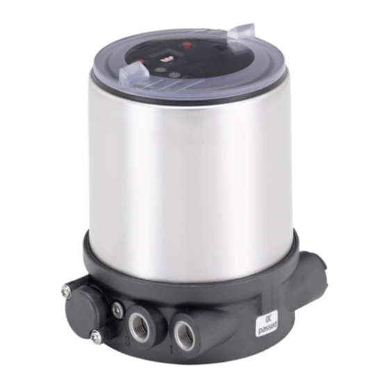
-
Contents
-
Table of Contents
-
Bookmarks
Quick Links
Type 8694
Positioner TopControl Basic
Electropneumatic position controller
Elektropneumatischer Stellungsregler
Positionneur électropneumatique
Operating Instructions
Bedienungsanleitung
Manuel d’utilisation
Related Manuals for Burkert 8694
Summary of Contents for Burkert 8694
-
Page 1
Type 8694 Positioner TopControl Basic Electropneumatic position controller Elektropneumatischer Stellungsregler Positionneur électropneumatique Operating Instructions Bedienungsanleitung Manuel d‘utilisation… -
Page 2
We reserve the right to make technical changes without notice. Technische Änderungen vorbehalten. Sous réserve de modifications techniques. © Bürkert Werke GmbH & Co. KG, 20 — 2017 Operating Instructions 1706/ _0080 / Original DE… -
Page 3: Table Of Contents
Features …………………………14 5.4.3 Function diagram of the positioner with single-acting actuator ……….15 Type 8694 positioner (position controller) ………………….16 5.5 5.5.1 Schematic representation of the position control Type 8694 ……….16 5.5.2 Functions of the position controller software …………….17 Interfaces of the positioner ……………………….19 5.6 TECHNICAL DATA ……………………………….20 6.1 Conformity ………………………………20…
-
Page 4
7.6.1 Error messages in MANUAL and AUTOMATIC operating statuses ………32 7.6.2 Error messages while the X.TUNE function is running …………..32 INSTALLATION ………………………………33 8.1 Safety instructions …………………………..33 8.2 Installation of the positioner Type 8694 on process valves of series 2103, 2300 and 2301 ..33 8.3 Installing the positioner Type 8694 on process valves belonging to series 26xx and 27xx ..36 8.4 Rotating the actuator module ……………………….40 8.5 Rotating the positioner for process valves belonging to series 26xx and 27xx …….42 PNEUMATIC INSTALLATION ………………………….43 Manual actuation of the actuator via pilot valves ………………..44 9.1… -
Page 5
Type 8694 10.2 Electrical installation with circular plug-in connector ………………46 10.2.1 Designation of the contacts Type 8694 ………………46 10.2.2 Connection of the positioner Type 8694 ………………47 10.3 Electrical installation with cable gland ……………………48 AS-INTERFACE INSTALLATION …………………………51 11.1 AS-Interface connection …………………………51 11.2 Maximum length of the bus line ……………………..51 11.3 Technical data for AS-Interface PCBs ……………………51 11.4 Programming data …………………………..52 11.5 Communication sequence for the version S-7.A.5 profile …………….53 11.6 LED status display …………………………..54 11.7 Electrical installation AS-interface ……………………..55… -
Page 6
Type 8694 13.2 Auxiliary functions ……………………………. 68 13.2.1. DIR.ACTUATOR — Effective direction of the actuator ………………..68 13.2.2. SPLITRANGE — Signal split range ……………………..69 13.2.3. X.LIMIT — Limiting the mechanical stroke range ………………..70 13.2.4. X.TIME — Limiting the control speed ……………………71 13.2.5. -
Page 7: Operating Instructions
▶ Designates an instruction to prevent risks. → Designates a procedure which you must carry out. 1.2 Definition of term / abbreviation The term “device” used in these instructions always stands for the positioner Type 8694. In these instructions, the abbreviation “Ex” always refers to “potentially explosive”. english…
-
Page 8: Authorized Use
▶ Correct transportation, correct storage and installation and careful use and maintenance are essential for reli- able and faultless operation. ▶ Use the positioner Type 8694 only as intended. 2.1 Restrictions If exporting the system/device, observe any existing restrictions.
-
Page 9: Basic Safety Instructions
General hazardous situations. To prevent injury, ensure: ▶ In the potentially explosion-risk area the positioner Type 8694 may be used only according to the specification on the separate approval sticker. For use observe the additional instructions enclosed with the device together with safety instructions for the explosion-risk area.
-
Page 10: General Information
And also on the Internet at: www.burkert.com 4.2 Warranty The warranty is only valid if the positioner Type 8694 is used as intended in accordance with the specified appli- cation conditions. 4.3 Trademarks Brands and trademarks listed below are trademarks of the corresponding companies / associations / organizations…
-
Page 11: System Description
Type 8694 Systemdescription SYSTEM DESCRIPTION 5.1 Intended application area The positioner Type 8694 is designed to be mounted on pneumatic actuators of process valves for the control of media. 5.2 Function of the positioner and combination with valve types Positioner Type 8694 is an electropneumatic position controller for pneumatically actuated control valves with single-acting actuators.
-
Page 12: Features Of The Valve Types
Type 8694 Systemdescription The position of the actuator is regulated according to the position set-point value. The position set-point value is specified by an external standard signal. Pneumatically actuated piston actuators and rotary actuators can be used as an actuator. Single-acting actuators are offered in combination with the positioner.
-
Page 13: Structure Of The Positioner
5.4 Structure of the positioner The positioner Type 8694 consists of the micro-processor controlled electronics, the position measuring system and the control system. The device is designed using three-wire technology. The positioner is operated via 2 keys and a 4-pole DIP switch. The pneumatic control system for single-acting actuators consists of 2 solenoid valves.
-
Page 14: Features
Type 8694 Systemdescription 5.4.2 Features • Models for single-acting valve actuators. • Position measuring system Contactless and therefore wear-free position measuring system. • Microprocessor-controlled electronics for signal processing, control and valve control. • Control module The device is controlled via 2 buttons and a 4-pole DIP switch. 2x 2-colored LEDs indicate different statuses of the device.
-
Page 15: Function Diagram Of The Positioner With Single-Acting Actuator
Type 8694 Systemdescription 5.4.3 Function diagram of the positioner with single-acting actuator The illustrated function diagram describes the function of the positioner (Type 8694). external position set-point value Position controller Actual Control system Positioner position 1: Aeration valve Control system 2: Bleed valve Pressure Position supply…
-
Page 16: Type 8694 Positioner (Position Controller)
Type 8694 Systemdescription 5.5 Type 8694 positioner (position controller) The position measuring system records the current position (POS) of the pneumatic actuator. The position controller compares this actual position value with the set-point value (CMD) which is definable as standard signal. In case of a control deviation (Xd1), a pulse-width modulated voltage signal is sent to the control system as a manipu- lated variable.
-
Page 17: Functions Of The Position Controller Software
Type 8694 Systemdescription 5.5.2 Functions of the position controller software Functions I • Activation via DIP switches • Parameter setting via communications software Additional function Effect Valve closes tight outside the control range. Specification Sealing function of the value (as %), from which the actuator is completely…
-
Page 18
Type 8694 Systemdescription Functions II • Activation and parameter setting via communications software Additional function Effect Standard signal for set-point value Select set-point value standard signal INPUT Effective direction of the actuator Assignment of the aeration status of the actuator chamber to the actual position. -
Page 19: Interfaces Of The Positioner
Figure 6: Interfaces The positioner Type 8694 is a 3-wire device, i.e. the power (24 V DC) is supplied separately from the set- point value signal. • Input for position set-point value (4 – 20 mA corresponds to 0 – 100 % (depending on position of DIP switch 1)).
-
Page 20: Technical Data
TECHNICAL DATA 6.1 Conformity In accordance with the EC Declaration of conformity, the positioner Type 8694 is compliant with the EC Directives. 6.2 Standards The applied standards on the basis of which compliance with the EC Directives is confirmed are listed in the EC type examination certificate and/or the EC Declaration of Conformity.
-
Page 21: Pneumatic Data
Socket connection G1/8 6.7 Type labels 6.7.1 Type label standard Example: Supply voltage / Control Control function — Pilot valve Type 8694 24 V DC Max. operating pressure single act Pilot 0,6 Pmax 7bar Max. ambient temperature Tamb 0°C — +60°C S/N 001000 00185134…
-
Page 22: Ul Type Label
Type 8694 Technicaldata 6.7.2 UL type label Example: Type; Features of the type code applicable to UL and ATEX Control function; pilot valve; Supply voltage pilot valve 8694 -E3-…-0 PU02 Single act Pilot 3.0 24V Max. operating pressure Pmax 7 bar Tamb -10 — +55 °C Max.
-
Page 23: Electrical Data With As-Interface Bus Control
Type 8694 Technicaldata Analogue position feedback max. load 560 Ω for current output 0/4 – 20 mA Binary input 0 – 5 V = log “0”, 12 — 30 V = log “1” inverted input in reverse order Communications interface Direct connection to PC via USB adapter with integrated interface driver, communication with communications software, see “Table 34: Accessories”.
-
Page 24: Factory Settings Of The Positioner
Type 8694 Technicaldata 6.9 Factory settings of the positioner Functions can be activated via DIP switches: Function Parameter Value CUTOFF Sealing function below Sealing function above 98 % CHARACT Select characteristic FREE DIR.CMD Effective direction set-point value rise Table 4: Factory settings — Functions I…
-
Page 25: Control And Display Elements
Type 8694 Controlanddisplayelements CONTROL AND DISPLAY ELEMENTS The following chapter describes the operating statuses as well as the control and display elements of the positioner. Further information on the operation of the positioner can be found in the chapter entitled “12 Start-up”. 7.1…
-
Page 26
Type 8694 Controlanddisplayelements The positioner features 2 buttons, 4-pole DIP switches and 2x 2-colored LEDs as a display element. NOTE! Breakage of the pneumatic connection pieces due to rotational impact. ▶ When unscrewing and screwing in the body casing or transparent cap, do not hold the actuator of the pro- cess valve but the connection housing. -
Page 27: Configuration Of The Keys
Type 8694 Controlanddisplayelements 7.3 Configuration of the keys The configuration of the 2 keys varies depending on the operating status (AUTOMATIC / MANUAL). The description of the operating statuses (AUTOMATIC / MANUAL) can be found in the chapter entitled “7.1 Operating status”. Version 1…
-
Page 28
Type 8694 Controlanddisplayelements MANUAL operating status (DIP switch 4 set to ON): Function Aerate (manually open / close the actuator) Deaerate (manually open / close the actuator) Table 6: Configuration of the keys for MANUAL operating status AUTOMATIC operating status (DIP switch 4 set to OFF): Function Press for 5 seconds to start the X.TUNE function… -
Page 29: Function Of The Dip Switches
Type 8694 Controlanddisplayelements 7.4 Function of the DIP switches 1 2 3 4 NOTE! Breakage of the pneumatic connection pieces due to rotational impact. ▶ When unscrewing and screwing in the body casing or transparent cap, do not hold the actuator of the pro- cess valve but the connection housing. → To operate the DIP switches, for…
-
Page 30
Type 8694 Controlanddisplayelements Information about the communications software: The switching position of the DIP switch has priority over the settings via the communications software. If the values of the sealing function (CUTOFF) or the correction characteristic (CHARACT) are changed via the communications software, the corresponding function must be active (DIP switches set to ON). -
Page 31: Display Of The Leds
Type 8694 Controlanddisplayelements 7.5 Display of the LEDs Version 1 Version 2 LED 1 LED 2 LED 1 Display of mode statuses (green / AUTO, MANUAL, red) X.TUNE and FAULT LED 2 Display of the actuator status (green / (open, closed, opens yellow)
-
Page 32: Error Messages
Type 8694 Controlanddisplayelements 7.6 Error messages 7.6.1 Error messages in MANUAL and AUTOMATIC operating statuses Display Cause of fault Remedial action LED 1 (red) Checksum error in data memory Not possible, device defective → Data memory defective → The device automatically switches to an older (possibly not current) data record.
-
Page 33: Installation
Type 8694 Installation INSTALLATION 8.1 Safety instructions DANGER! Risk of injury from high pressure in the equipment/device. ▶ Before working on equipment or device, switch off the pressure and deaerate/drain lines. Risk of electric shock. ▶ Before working on equipment or device, switch off the power supply and secure to prevent reactivation.
-
Page 34
Type 8694 Installation → For version with plug-in hose connector, remove the collets (white nozzles) from both pilot air ports (if present). Puck Switch spindle Guide element Groove ring max. 1 Nm max. 5 Nm Actuator cover O-ring Spindle extension… -
Page 35
Type 8694 Installation 2. Install sealing rings → Pull the form seal onto the actuator cover (smaller diameter points upwards). → Check that the O-rings are correctly positioned in the pilot air ports. When the positioner is being installed, the collets of the pilot air ports must not be fitted to the actuator. -
Page 36: Installing The Positioner Type 8694 On Process Valves Belonging To Series 26Xx And 27Xx
Type 8694 Installation → Push the positioner, without turning it, onto the actuator until no gap is visible on the form seal. NOTE! Too high torque when screwing in the fastening screw does not ensure degree of protection IP65 / IP67. ▶ The fastening screws may be tightened to a maximum torque of 1.5 Nm only.
-
Page 37
Type 8694 Installation Puck Switch spindle Guide element O-ring Plastic part (Switch spindle) Spindle (actuator) Figure 25: Installing the switch spindle (2), series 26xx and 27xx → Press the O-ring downwards into the cover of the actuator. → Actuator size 125 and bigger with high air flow rate: remove existing spindle extension and replace with the new one. -
Page 38
Type 8694 Installation 2. Install positioner → Push the positioner onto the actuator. The puck must be aligned in such a way that it is inserted into the guide rail of the positioner. NOTE! Damaged printed circuit board or malfunction. ▶ Ensure that the puck is situated flat on the guide rail. -
Page 39
Type 8694 Installation 3. Install pneumatic connection between positioner and actuator Pilot air outlet 2 Pilot air outlet 2 Upper pilot air port Lower pilot air port Example ∅ 80, CFA Figure 28: Installing the positioner → Screw the plug-in hose connectors onto the positioner and the actuator. -
Page 40: Rotating The Actuator Module
Dry area Table 14: Pneumatic connection to actuator — CFB «In rest position» means that the pilot valves of the positioner Type 8694 are isolated or not actuated. 8.4 Rotating the actuator module The actuator module (positioner and actuator) can be rotated for straight seat valves and angle seat valves belonging to series 2300, 2301 and 27xx only.
-
Page 41
Type 8694 Installation Actuator module Key contour Hexagon Nipple Nipple with hexagon without hexagon Figure 29: Rotating the actuator module → Using a suitable open-end wrench, counter the wrench flat on the pipe. → Actuator module without hexagon: Fit special key exactly in the key contour on the underside of the actuator. -
Page 42: Rotating The Positioner For Process Valves Belonging To Series 26Xx And 27Xx
Type 8694 Installation 8.5 Rotating the positioner for process valves belonging to series 26xx and 27xx If the connecting cables or hoses cannot be fitted properly following installation of the process valve, the positioner can be rotated contrary to the actuator. Fastening screw (2x) Positioner Pneumatic connection Actuator Figure 31:…
-
Page 43: Pneumatic Installation
Type 8694 Pneumaticinstallation PNEUMATIC INSTALLATION DANGER! Risk of injury from high pressure in the equipment/device. ▶ Before working on equipment or device, switch off the pressure and deaerate/drain lines. WARNING! Risk of injury from improper installation. ▶ Installation may be carried out by authorized technicians only and with the appropriate tools. Risk of injury from unintentional activation of the system and an uncontrolled restart. ▶ Secure system from unintentional activation.
-
Page 44: Manual Actuation Of The Actuator Via Pilot Valves
Hand lever for aerate to the left Pilot valve for deaerate Pilot valve activated Hand lever Type 8694 for high air flow rate to the right Pilot valve for aerate Pilot valve for deaerate Figure 33: Pilot valves for aerate and deaerate the actuator…
-
Page 45
→ 2. Actuate hand lever pilot valve aeration. Both hand levers point to the right. The actuator moves to the end position. Type 8694 for high air flow rate Figure 34: Move actuator to end position Move actuator back to the rest position Turn the hand levers to the left using a screwdriver. -
Page 46: Electrical Installation 24 V Dc
Type 8694 Electricalinstallation24VDC ELECTRICAL INSTALLATION 24 V DC All electrical inputs and outputs of the device are not galvanically isolated from the supply voltage. Two kinds of connections are used for the electrical bonding of the positioner: • Cable gland with cable gland M16 x 1.5 and screw-type terminals •…
-
Page 47: Connection Of The Positioner Type 8694
Type 8694 Electricalinstallation24VDC 10.2.2 Connection of the positioner Type 8694 → Connect the pins according to the model (options) of the positioner. Input signals of the control center (e.g. PLC) — circular plug M12 x 1, 8-pole Wire color Configuration External circuit / signal level Set-point value + (0/4 – 20 mA) white + (0/4 …
-
Page 48: Electrical Installation With Cable Gland
Type 8694 Electricalinstallation24VDC 10.3 Electrical installation with cable gland DANGER! Risk of electric shock. ▶ Before working on equipment or device, switch off the power supply and secure to prevent reactivation. ▶ Observe applicable accident prevention and safety regulations for electrical equipment. NOTE! Breakage of the pneumatic connection pieces due to rotational impact. ▶ When unscrewing and screwing in the body casing, do not hold the actuator of the process valve but the connection housing.
-
Page 49
Type 8694 Electricalinstallation24VDC Figure 38: Connection of screw-type terminals → Connect the positioner according to the following tables: Input signals from the control centre (e.g. PLC) Terminal Configuration External circuit + (0/4 … 20 mA) Set-point value + Set-point value GND Binary input + 0 … -
Page 50
Type 8694 Electricalinstallation24VDC Body casing Seal body casing Connection housing Figure 39: Position of the seal in the body casing → Check that the seal is correctly positioned in the body casing. NOTE! Breakage of the pneumatic connection pieces due to rotational impact. ▶ When unscrewing and screwing in the body casing, do not hold the actuator of the process valve but the connection housing. -
Page 51: As-Interface Installation
Type 8694 AS-Interfaceinstallation AS-INTERFACE INSTALLATION 11.1 AS-Interface connection AS-Interface (Actuator Sensor Interface) is a field bus system which is used primarily for networking binary sensors and actuators (slaves) with a higher-level control (master). Bus line Unshielded two-wire line (AS-Interface line as AS-Interface flat cable) along which both information (data) and energy (power supply for the actuators and sensors) are transmitted.
-
Page 52: Programming Data
Type 8694 AS-Interfaceinstallation 11.4 Programming data Version Profile S-7.3.4 Version Profile S-7.A.5 I/O configuration 7 hex 7 hex ID code 3 hex (analog profile) A hex F hex Extended ID code 1 7 hex (Default value, can be changed by the user)
-
Page 53: Communication Sequence For The Version S-7.A.5 Profile
Type 8694 AS-Interfaceinstallation 11.5 Communication sequence for the version S-7.A.5 profile 1. Following start-up, the AS-Interface master (from master class 4) automatically replaces the ID object with the S-7.A.5 slave. Master transmits 3 bytes: S-7.A.5 slave replies with 6 bytes 1. Byte: Code = 16 dez 1.
-
Page 54: Led Status Display
Type 8694 AS-Interfaceinstallation 11.6 LED status display NOTE! Breakage of the pneumatic connection pieces due to rotational impact. ▶ When unscrewing and screwing in the body casing, do not hold the actuator of the process valve but the connection housing. The LED status display indicates the bus status (LED green and red).
-
Page 55: Electrical Installation As-Interface
Type 8694 AS-Interfaceinstallation → Check that the seal is correctly positioned in the body casing. NOTE! Breakage of the pneumatic connection pieces due to rotational impact. ▶ When unscrewing and screwing in the body casing, do not hold the actuator of the process valve but the connection housing. Damage or malfunction due to penetration of dirt and humidity.
-
Page 56: Connection With Circular Plug-In Connector M12 X 1, 4-Pole, Male
(M12 circular plug) and ribbon cable terminal. The wiring diagram of the circular plug corresponds to the bus con- nection of the M12 4-pole circular plug (see “Figure 42” and “Figure 43”) and can easily be connected to the ribbon cable terminal (see “Figure 45”). Figure 44: Positioner 8694 with multi-pole cable and ribbon cable terminal english…
-
Page 57
Type 8694 AS-Interfaceinstallation Calculated bus line length: When designing the system, consider the length of the cable which is fed directly to the positioner for the maximum bus line length (multi-pole cable and cable inside: 1.0 m). Example calculation: When using 62 positioner with multi-pole cable, the AS-Interface flat cable may still be maximum 38 m long. -
Page 58: Start-Up
Type 8694 Start-up START-UP 12.1 Safety instructions DANGER! Risk of injury from high pressure in the equipment/device. ▶ Before working on equipment or device, switch off the pressure and deaerate/drain lines. WARNING! Risk of injury from improper operation. Improper operation may result in injuries as well as damage to the device and the area around it.
-
Page 59
Type 8694 Start-up NOTE! Breakage of the pneumatic connection pieces due to rotational impact. ▶ When unscrewing and screwing in the body casing or transparent cap, do not hold the actuator of the pro- cess valve but the connection housing. → To operate the DIP switches, for Version 1:… -
Page 60
Type 8694 Start-up Body casing Seal body casing Connection housing Figure 48: Position of the seal in the body casing → Version 1: Check that the seal is correctly positioned in the body casing. NOTE! Breakage of the pneumatic connection pieces due to rotational impact. ▶ When unscrewing and screwing in the body casing or transparent cap, do not hold the actuator of the pro- cess valve but the connection housing. -
Page 61: Operation And Function
Type 8694 Operationandfunction OPERATION AND FUNCTION The positioner type 8694 has different basic and additional functions which can be configured and parameterized via the DIP switches or the communications software. 13.1 Basic functions The following basic functions can be activated via the DIP switches (CUTOFF and CHARACT) or changed (DIR.CMD).
-
Page 62: Dir.cmd
Type 8694 Operationandfunction 13.1.1 DIR.CMD — Effective direction of the positioner set-point value You can use this function to adjust the effective direction between the input signal (INPUT) and the nominal position of the actuator. Factory setting: DIP switch set to OFF (ascending) DIP Switches Position Function Reversal of the effective direction of the set-point value (DIR.CMD)
-
Page 63: Cutoff
Type 8694 Operationandfunction 13.1.2 CUTOFF — Sealing function for the positioner This function causes the valve to be sealed outside the control range. Control mode resumes at a hysteresis of 1%. Factory setting: DIP switch 2 set to OFF (no sealing function) DIP Switches Position Function Sealing function active.
-
Page 64: Charact
Type 8694 Operationandfunction 13.1.3 CHARACT — Select the transfer characteristic between input signal (position set-point value) and stroke Characteristic (customer-specific characteristic) This function can be used to activate a transfer characteristic with respect to set-point value (set-point position) and valve stroke for correction of the flow-rate or operating characteristic. The transfer characteristic can be changed via the communications software only.
-
Page 65
Type 8694 Operationandfunction The flow characteristic k = f(s) indicates the flow-rate of a valve, expressed by the value k as a function of the stroke s of the actuator spindle. It is determined by the design of the valve seat and the seat seal. In general two types of flow characteristics are implemented, the linear and the equal percentage. -
Page 66: Input — Enter The Input Signal
Type 8694 Operationandfunction Entering the freely programmable characteristic The characteristic is defined by 21 nodes distributed uniformly over the position set-point values ranging from 0 – 100%. They are spaced at intervals of 5%. A freely selectable stroke (adjustment range 0 – 100%) is assigned to each node.
-
Page 67: Reset
Type 8694 Operationandfunction 13.1.5 RESET — Reset to factory settings This function can be used to reset the positioner to the factory settings. 13.1.6 X.TUNE — Automatic adjustment of the positioner to the relevant operating conditions The X.TUNE function must be run for a function check of the positioner to adjust to specific local features.
-
Page 68: Auxiliary Functions
Type 8694 Operationandfunction 13.2 Auxiliary functions The following additional functions can be configured and parameterized via the communications software: Function Description DIR.ACTUATOR Assignment of the aeration status of the actuator chamber to the actual position SPLITRANGE Signal split range; input signal as a % for which the valve runs through the entire stroke range.
-
Page 69: Splitrange — Signal Split Range
Type 8694 Operationandfunction 13.2.2 SPLITRANGE — Signal split range Minimum and maximum values of the input signal as a % for which the valve runs through the entire stroke range. Factory setting: Lower signal range split = 0 %; Upper signal range split = 100 %…
-
Page 70: X.limit
Type 8694 Operationandfunction 13.2.3 X.LIMIT — Limiting the mechanical stroke range This function limits the (physical) stroke to specified % values (lower and upper). In doing so, the stroke range of the limited stroke is set equal to 100 %. If the limited stroke range is left during operation, negative actual posi- tions or actual positions greater than 100 % are shown.
-
Page 71: X.time
Type 8694 Operationandfunction 13.2.4 X.TIME — Limiting the control speed Use this function to specify the opening and closing times for the entire stroke and thereby limit control speeds. When the X.TUNE function is running, the minimum opening and closing time for the entire stroke is auto- matically entered for Open and Close.
-
Page 72: X.control
Type 8694 Operationandfunction 13.2.5 X.CONTROL — Parameterization of the positioner Use this function to set the parameters for the positioner (dead band and amplification factors (kp)). Deadband: Insensitivity range of the positioner Entry for the deadband as a % in reference to the scaled stroke range;…
-
Page 73: Signal.error
Type 8694 Operationandfunction 13.2.7 SIGNAL.ERROR — Configuration of signal level fault detection The SIGNAL ERROR function is used to detect a fault on the input signal. Fault detection Fault detection can be selected for a 4 – 20 mA signal only: Fault if input signal ≤ 3.5 mA (± 0.5 % of final value, hysteresis 0.5 % of final value) If 0 –…
-
Page 74: Output (Optional)
Type 8694 Operationandfunction 13.2.9 OUTPUT (optional) — Configuration of the analog output The OUTPUT menu item only appears in the selection of auxiliary functions if the positioner has an analog output (optional) or if no parameters have been read in yet. The analog output can be used for feedback of the current position or of the set-point value to the control center.
-
Page 75: Safety End Positions
Type 8694 Safetyendpositions SAFETY END POSITIONS 14.1 Safety end positions after failure of the electrical or pneumatic auxiliary power Safety end positions after failure of the auxiliary power Actuator system Designation electrical pneumatic pilot-controlled control system: single-acting down down Control direct-acting control function A system: down not defined pilot-controlled control system: single-acting Control direct-acting control function B system: down not defined…
-
Page 76: Maintenance
Type 8694 Maintenance MAINTENANCE 15.1 Safety instructions DANGER! Risk of injury from high pressure in the equipment/device. ▶ Before working on equipment or device, switch off the pressure and deaerate/drain lines. Risk of electric shock. ▶ Before working on equipment or device, switch off the power supply and secure to prevent reactivation.
-
Page 77: Service At The Air Intake Filter
Type 8694 Maintenance 15.2 Service at the air intake filter DANGER! Risk of injury from high pressure in the equipment/device. ▶ Before working on equipment or device, switch off the pressure and deaerate/drain lines. To protect the internal solenoid valves and the actuator, the pilot air is filtered. The direction of flow of the air intake filter in installed state is from the inside to the outside through the filter material.
-
Page 78: Accessories
Type 8694 Accessories ACCESSORIES Designation Order no. USB adapter for connection to a PC in conjunction with an extension cable 227093 Communicator Information at www.burkert.com Connection cable M12 x 1, 8-pole 919061 Assembly tool 647077 Table 34: Accessories 16.1 Communications software The PC operating program “Communicator” is designed for communication with the devices from the Bürkert posi- tioner family (valid since serial number 20000).
-
Page 79: Disassembly
Type 8694 Disassembly DISASSEMBLY 17.1 Safety instructions DANGER! Risk of injury from high pressure in the equipment/device. ▶ Before working on equipment or device, switch off the pressure and deaerate/drain lines. Risk of electric shock. ▶ Before working on equipment or device, switch off the power supply and secure to prevent reactivation.
-
Page 80
Type 8694 Disassembly 2. Electrical connection DANGER! Risk of electric shock. ▶ Before working on equipment or device, switch off the power supply and secure to prevent reactivation. ▶ Observe applicable accident prevention and safety regulations for electrical equipment. Circular plug-in connector: →… -
Page 81: Packaging And Transport
Type 8694 Packagingandtransport PACKAGING AND TRANSPORT NOTE! Transport damages. Inadequately protected equipment may be damaged during transport. ▶ During transportation protect the device against wet and dirt in shock-resistant packaging. ▶ Avoid the effects of heat and cold which could result in temperatures above or below the permitted storage temperature.
-
Page 82
Type 8694 english… -
Page 83
Darstellung ……………………….91 5.4.2 Merkmale …………………………92 5.4.3 Funktionsschema des Positioners mit einfachwirkendem Antrieb ……….93 Typ 8694 Positioner (Stellungsregler) ……………………94 5.5 5.5.1 Schematische Darstellung der Stellungsregelung Typ 8694 ……….94 5.5.2 Funktionen der Stellungsregler-Software ………………95 Schnittstellen des Positioners ……………………….97 5.6 TECHNISCHE DATEN …………………………….98 Konformität……………………………….98 6.1 6.2 Normen . -
Page 84
Typ 8694 6.4 Betriebsbedingungen ………………………….98 6.5 Mechanische Daten …………………………..99 6.6 Pneumatische Daten ……………………………99 6.7 Typschilder ……………………………….99 6.7.1 Typschild Standard ……………………..99 6.7.2 UL-Typschild……………………….100 6.7.3 UL-Zusatzschild ……………………..100 6.8 Elektrische Daten …………………………..100 6.8.1 Elektrische Daten ohne Busansteuerung 24 V DC …………..100 6.8.2 Elektrische Daten mit Busansteuerung AS-Interface …………. -
Page 85
Typ 8694 10.2 Elektrische Installation mit Rundsteckverbinder ……………….. 124 10.2.1 Bezeichnung der Kontakte Typ 8694 ………………124 10.2.2 Anschluss des Positioners Typ 8694 ………………125 10.3 Elektrische Installation mit Kabelverschraubung ………………. 126 AS-INTERFACE-INSTALLATION ……………………….. 129 11.1 AS-Interface-Anschaltung ……………………….129 11.2 Maximale Länge der Bus-Leitung ……………………… 129 11.3 Technische Daten für AS-Interface-Platinen . -
Page 86
Typ 8694 13.2 Zusatzfunktionen …………………………….146 13.2.1. DIR.ACTUATOR — Wirkrichtung (Direction) des Stellantriebs …………….146 13.2.2. SPLITRANGE — Signalbereichsaufteilung (Split range) ………………147 13.2.3. X.LIMIT — Begrenzung des mechanischen Hubbereichs …………….148 13.2.4. X.TIME — Begrenzung der Stellgeschwindigkeit ………………149 13.2.5. -
Page 87: Die Bedienungsanleitung
▶ markiert eine Anweisung zur Gefahrenvermeidung. → markiert einen Arbeitsschritt, den Sie ausführen müssen. 1.2 Begriffsdefinition / Abkürzung Der in dieser Anleitung verwendete Begriff „Gerät“ steht immer für den Positioner Typ 8694. Die in dieser Anleitung verwendete Abkürzung „Ex“ steht immer für „explosionsgefährdet“. deutsch…
-
Page 88: Bestimmungsgemässe Verwendung
Positioner für den konkreten Einsatzfall geeignet ist. ▶ Voraussetzungen für den sicheren und einwandfreien Betrieb sind sachgemäßer Transport, sachgemäße Lagerung und Installation sowie sorgfältige Bedienung und Instandhaltung. ▶ Positioner Typ 8694 nur bestimmungsgemäß verwenden. 2.1 Beschränkungen Beachten Sie bei der Ausfuhr des Systems/Geräts gegebenenfalls bestehende Beschränkungen.
-
Page 89: Grundlegende Sicherheitshinweise
Allgemeine Gefahrensituationen. Zum Schutz vor Verletzungen ist zu beachten: ▶ Im explosionsgefährdeten Bereich darf der Positioner Typ 8694 nur entsprechend der Spezifikation auf dem separaten Klebeschild für die Zulassung eingesetzt werden. Für den Einsatz muss die dem Gerät beiliegende Zusatzanleitung mit Sicherheitshinweisen für den Ex-Bereich beachtet werden.
-
Page 90: Allgemeine Hinweise
Die Kontaktadressen finden Sie auf den letzten Seiten der gedruckten Bedienungsanleitung. Außerdem im Internet unter: www.burkert.com 4.2 Gewährleistung Voraussetzung für die Gewährleistung ist der bestimmungsgemäße Gebrauch des Positioners Typ 8694 unter Beachtung der spezifizierten Einsatzbedingungen. 4.3 Warenzeichen Die aufgeführten Marken sind Warenzeichen der entsprechenden Firmen / Vereine / Organisationen…
-
Page 91: Systembeschreibung
Typ 8694 Systembeschreibung SYSTEMBESCHREIBUNG 5.1 Vorgesehener Einsatzbereich Der Positioner Typ 8694 ist für den Anbau an pneumatische Antriebe von Prozessventilen zur Steuerung von Medien vorgesehen. 5.2 Funktion des Positioners und Kombination mit Ventiltypen Der Positioner Typ 8694 ist ein elektropneumatischer Stellungsregler für pneumatisch betätigte Stellventile mit einfachwirkenden Antrieben.
-
Page 92: Merkmale Der Ventiltypen
Typ 8694 Systembeschreibung Die Stellung des Antriebs wird entsprechend des Stellungs-Sollwerts geregelt. Der Stellungs-Sollwert wird durch ein externes Normsignal vorgegeben. Als Antrieb können pneumatisch betätigte Kolbenantriebe und Drehantriebe verwendet werden. In Kombination mit dem Positioner werden einfachwirkende Antriebe angeboten. Bei einfachwirkenden Antrieben wird nur eine Kammer im Antrieb be- und entlüftet. Der entstehende Druck arbeitet gegen eine Feder.
-
Page 93: Aufbau Des Positioners
5.4 Aufbau des Positioners Der Positioner Typ 8694 besteht aus der mikroprozessor gesteuerten Elektronik, dem Wegmesssystem und dem Stell- system. Das Gerät ist in Dreileitertechnik ausgeführt. Die Bedienung des Positioners erfolgt über 2 Tasten und einen 4-poligen DIP-Schalter. Das pneumatische Stellsystem für einfachwirkende Antriebe besteht aus 2 Magnetventilen.
-
Page 94: Merkmale
Typ 8694 Systembeschreibung 5.4.2 Merkmale • Ausführungen für einfachwirkende Ventilantriebe. • Wegmesssystem Berührungsloses und damit verschleißfreies Wegmesssystem. • Mikroprozessorgesteuerte Elektronik für die Signalverarbeitung, Regelung und Ventilansteuerung. • Bedienmodul Die Bedienung des Geräts erfolgt über 2 Tasten und 4-poligen DIP-Schalter. 2 je 2-farbige LEDs ermöglichen die Anzeige verschiedener Gerätestatus.
-
Page 95: Funktionsschema Des Positioners Mit Einfachwirkendem Antrieb
Typ 8694 Systembeschreibung 5.4.3 Funktionsschema des Positioners mit einfachwirkendem Antrieb Das dargestellte Funktionsschema beschreibt die Funktion des Positioners Typ 8694. externer Stellungs- Sollwert Stellungs- regler Ist-Position Stellsystem Positioner 1: Belüftungsventil Stellsystem 2: Entlüftungsventil Druckver- Wegmess- sorgung system Abluft Pneumatischer Antrieb (einfachwirkend) Ventil (Stellglied) Bild 3:…
-
Page 96: Typ 8694 Positioner (Stellungsregler)
Typ 8694 Systembeschreibung 5.5 Typ 8694 Positioner (Stellungsregler) Über das Wegmesssystem wird die aktuelle Position (POS) des pneumatischen Antriebs erfasst. Dieser Stellungs- Istwert wird vom Stellungsregler mit dem als Normsignal vorgebbaren Sollwert (CMD) verglichen. Liegt eine Regel- differenz (Xd1) vor, wird als Stellgröße an das Stellsystem ein pulsweitenmoduliertes Spannungssignal gegeben. Bei einfachwirkenden Antrieben wird bei positiver Regeldifferenz über den Ausgang B1 das Belüftungsventil angesteuert.
-
Page 97: Funktionen Der Stellungsregler-Software
Typ 8694 Systembeschreibung 5.5.2 Funktionen der Stellungsregler-Software Funktionen I • Aktivierung über DIP-Schalter • Parametereinstellung über Kommunikation-Software Zusatzfunktion Wirkung Ventil schließt außerhalb des Regelbereichs dicht. Dichtschließfunktion Angabe des Werts (in %), ab dem der Antrieb vollständig entlüftet (bei 0 %) bzw. belüftet (bei 100 %) wird CUTOFF (siehe Kapitel „7.4 Funktion der DIP-Schalter“).
-
Page 98
Typ 8694 Systembeschreibung Funktionen II • Aktivierung und Parametereinstellung über Kommunikation-Software Zusatzfunktion Wirkung Normsignal für Sollwert Auswahl Sollwert-Normsignal INPUT Wirkrichtung des Aktuators Zuordnung des Belüftungszustands der Antriebskammer zur Istpostion. DIR.ACTUATOR Signalbereichsaufteilung Normsignal in %, für den das Ventil den gesamten Hub- bereich durchläuft. -
Page 99: Schnittstellen Des Positioners
Bus-Anschaltung AS-Interface Default-Einstellung Bild 6: Schnittstellen Der Positioner Typ 8694 ist ein 3-Leiter-Gerät, d. h. die Versorgungsspannung (24 V DC) erfolgt getrennt vom Sollwertsignal. • Eingang für Stellungs-Sollwert (4…20 mA entspricht 0…100 % (abhängig von Stellung des DIP-Schalters 1)).
-
Page 100: Technische Daten
Typ 8694 TechnischeDaten TECHNISCHE DATEN 6.1 Konformität Der Positioner, Typ 8694 ist konform zu den EG-Richtlinien entsprechend der EG-Konformitätserklärung. 6.2 Normen Die angewandten Normen, mit denen die Konformität mit den EG-Richtlinien nachgewiesen wird, sind in der EG- Baumusterprüfbescheinigung und/oder der EG-Konformtätserklärung nachzulesen.
-
Page 101: Mechanische Daten
Schlauchsteckverbinder Ø6 mm / 1/4“ Muffenanschluss G1/8 6.7 Typschilder 6.7.1 Typschild Standard Beispiel: Betriebsspannung / Ansteuerung Steuerfunktion — Steuerventil 8694 24 V DC Max. Betriebsdruck single act Pilot 0,6 Pmax 7 bar Tamb 0°C — +55°C Max. Umgebungstemperatur S/N 001000 00185134…
-
Page 102: Ul-Typschild
Typ 8694 TechnischeDaten 6.7.2 UL-Typschild Beispiel: Typ; für UL und ATEX geltende Merkmale des Typschlüssels Steuerfunktion; Steuerventil; Versorgungsspannung 8694 -E3-…-0 PU02 Steuerventil Single act Pilot 3.0 24V Max. Betriebsdruck Pmax 7 bar Tamb -10 — +55 °C Max. Umgebungstemperatur S/N 1001 Seriennummer;…
-
Page 103: Elektrische Daten Mit Busansteuerung As-Interface
Typ 8694 TechnischeDaten Analoge Stellungsrückmeldung max. Bürde 560 Ω für Stromausgang 0/4…20 mA Digitaleingang 0…5 V = log „0“, 12…30 V = log „1“ invertierter Eingang entsprechend umgekehrt Kommunikationsschnittstelle Direkter Anschluss an PC über USB-Adapter mit integriertem Schnittstellentreiber, Kommunikation mit Kommunikation-Software, siehe „Tabelle 34: Zubehör“.
-
Page 104: Werkseinstellungen Des Positioners
Typ 8694 TechnischeDaten 6.9 Werkseinstellungen des Positioners Über DIP-Schalter aktivierbare Funktionen: Funktion Parameter Wert CUTOFF Dichtschließfunktion unten Dichtschließfunktion oben 98 % CHARACT Auswahl Kennlinie FREE DIR.CMD Wirkrichtung Sollwert steigend Tabelle 4: Werkseinstellungen — Funktionen I Über Kommunikation-Software aktivierbare Funktionen: Funktion Parameter Wert…
-
Page 105: Bedien- Und Anzeigeelemente
Typ 8694 Bedien-undAnzeigeelemente BEDIEN- UND ANZEIGEELEMENTE Das folgende Kapitel beschreibt die Betriebszustände, sowie die Bedien- und Anzeigeelemente des Positioners. Weitere Informationen zur Bedienung des Positioners finden Sie im Kapitel „12 Inbetriebnahme“. 7.1 Betriebszustand AUTOMATIK (AUTO) Im Betriebszustand AUTOMATIK wird der normale Reglerbetrieb ausgeführt und überwacht.
-
Page 106
Typ 8694 Bedien-undAnzeigeelemente Der Positioner ist mit 2 Tasten, 4-poligen DIP-Schalter und 2 je 2-farbige LEDs als Anzeigeelement ausgestattet. HINWEIS! Bruch der pneumatischen Verbindungsstutzen durch Dreheinwirkung. ▶ Beim Abschrauben und Einschrauben des Gehäusemantels oder der Klarsichthaube nicht am Antrieb des Prozessventils sondern am Anschlussgehäuse gegenhalten. -
Page 107: Belegung Der Tasten
Typ 8694 Bedien-undAnzeigeelemente 7.3 Belegung der Tasten Die Belegung der 2 Tasten sind je nach Betriebszustand (AUTOMATIK / HAND) unterschiedlich. Die Beschreibung der Betriebszustände (AUTOMATIK / HAND) finden Sie im Kapitel„7.1 Betriebszustand“. Version 1 Version 2 Taste 1 Taste 2 Taste 1…
-
Page 108
Typ 8694 Bedien-undAnzeigeelemente Betriebszustand HAND (DIP-Schalter 4 auf ON): Taste Funktion Belüften (manuelles Auf- / Zufahren des Antriebs) Entlüften (manuelles Auf- / Zufahren des Antriebs) Tabelle 6: Tastenbelegung Betriebszustand HAND Betriebszustand AUTOMATIK (DIP-Schalter 4 auf OFF): Taste Funktion durch 5 Sekunden langes Drücken startet die Funktion X.TUNE… -
Page 109: Funktion Der Dip-Schalter
Typ 8694 Bedien-undAnzeigeelemente 7.4 Funktion der DIP-Schalter 1 2 3 4 HINWEIS! Bruch der pneumatischen Verbindungsstutzen durch Dreheinwirkung. ▶ Beim Abschrauben und Einschrauben des Gehäusemantels oder der Klarsichthaube nicht am Antrieb des Prozessventils sondern am Anschlussgehäuse gegenhalten. → Um die DIP-Schalter zu bedienen, bei Version 1: den Gehäusemantel…
-
Page 110
Typ 8694 Bedien-undAnzeigeelemente Hinweise zur Kommunikation-Software: Die Schaltstellung des DIP-Schalters hat Vorrang vor Einstellungen über die Kommunikation-Software. Wenn die Werte der Dichtschließfunktion (CUTOFF) oder der Korrekturkennlinie (CHARACT) über die Kom- munikation-Software geändert werden, muss die entsprechende Funktion aktiv sein (DIP-Schalter auf ON). -
Page 111: Anzeige Der Leds
Typ 8694 Bedien-undAnzeigeelemente 7.5 Anzeige der LEDs Version 1 Version 2 LED 1 LED 2 LED 1 Anzeige der Zustände AUTO, HAND, (grün / rot) X.TUNE und FEHLER LED 2 Anzeige des Zustandes des (grün / gelb) Antriebs (offen, geschlossen, öffnet oder schließt)
-
Page 112: Fehlermeldungen
Typ 8694 Bedien-undAnzeigeelemente 7.6 Fehlermeldungen 7.6.1 Fehlermeldungen in den Betriebszuständen HAND und AUTOMATIK Anzeige Fehlerursache Abhilfe LED 1 (rot) Checksum-Fehler im Datenspeicher nicht möglich, Gerät defekt → Datenspeicher defekt → Das Gerät schaltet automatisch in einen älteren (eventuell nicht aktuellen) Datensatz Tabelle 11: Fehlermeldungen in den Betriebszuständen 7.6.2…
-
Page 113: Montage
Typ 8694 Montage MONTAGE 8.1 Sicherheitshinweise GEFAHR! Verletzungsgefahr durch hohen Druck in Anlage/Gerät. ▶ Vor Arbeiten an Anlage oder Gerät, den Druck abschalten und Leitungen entlüften/entleeren. Gefahr durch Stromschlag. ▶ Vor Arbeiten an Anlage oder Gerät, die Spannung abschalten und vor Wiedereinschalten sichern. ▶ Die geltenden Unfallverhütungs- und Sicherheitsbestimmungen für elektrische Geräte beachten.
-
Page 114
Typ 8694 Montage → Bei Variante mit Schlauchsteckverbinder die Collets (weiße Tüllen) aus den beiden Steuerluftanschlüssen entfernen (falls vorhanden). Puck Schaltspindel Führungselement Nutring max. 1 Nm max. 5 Nm Antriebsdeckel O-Ring Spindelverlängerung Bild 20: Montage der Schaltspindel (2), Reihe 2103, 2300 und 2301 HINWEIS! Unsachgemäße Montage kann den Nutring im Führungselement beschädigen. -
Page 115
Typ 8694 Montage 2. Dichtringe montieren → Formdichtung auf den Antriebsdeckel aufziehen (kleinerer Durchmesser zeigt nach oben). → Korrekte Position der O-Ringe in den Steuerluftanschlüssen prüfen. Bei der Montage des Positioners dürfen die Collets der Steuerluftanschlüsse am Antrieb nicht montiert sein. Formdichtung Steuerluftanschlüsse… -
Page 116: Montage Des Positioners Typ 8694 An Prozessventile Der Reihe 26Xx Und 27Xx
Typ 8694 Montage → Positioner ohne Drehbewegung soweit auf den Antrieb schieben, dass an der Formdichtung kein Spalt mehr sichtbar ist. HINWEIS! Durch ein zu hohes Drehmoment beim Einschrauben der Befestigungsschraube kann die Schutzart IP65 / IP67 nicht sichergestellt werden. ▶ Befestigungsschrauben nur mit einem maximalen Drehmoment von 1,5 Nm anziehen. → Positioner mit den beiden seitlichen Befestigungsschrauben auf dem Antrieb befestigen. Dabei die Schrauben nur leicht anziehen (maximales Drehmoment: 1,5 Nm).
-
Page 117
Typ 8694 Montage Puck Schaltspindel Führungselement O-Ring Kunststoffteil (der Schaltspindel) Spindel (Antrieb) Bild 25: Montage der Schaltspindel (2), Reihe 26xx und 27xx → O-Ring nach unten in den Deckel des Antriebs drücken. → Antriebsgröße 125 und größer mit hoher Luftleistung: vorhandene Spindelverlängerung demontieren und durch die neue ersetzen. -
Page 118
Typ 8694 Montage 2. Positioner montieren → Positioner auf den Antrieb schieben. Dabei den Puck so ausrichten, dass er in die Führungsschiene des Posi- tioners hineinfindet. HINWEIS! Beschädigung der Platine oder Funktionsausfall. ▶ Darauf achten, dass der Puck plan auf der Führungsschiene aufliegt. Führungsschiene Puck Bild 26: Ausrichten des Pucks →… -
Page 119
Typ 8694 Montage 3. Pneumatische Verbindung Positioner — Antrieb montieren Steuerluftausgang 2 Steuerluftausgang 2 Steuerluftanschluss oben Steuerluftanschluss Beispiel ∅80, SFA unten Bild 28: Montage der pneumatischen Verbindungen → Schlauchsteckverbinder an den Positioner und den Antrieb schrauben. → Mit den im Zubehörsatz mitgelieferten Schläuchen die pneumatische Verbindung zwischen Positioner und Antrieb mit „Tabelle 13: Pneumatische Verbindung mit Antrieb — SFA“… -
Page 120: Drehen Des Antriebsmoduls
Steuerlufteingang unten Trockene Umgebung Tabelle 14: Pneumatische Verbindung mit Antrieb — SFB „In Ruhestellung“ bedeutet, dass die Steuerventile des Positioners Typ 8694 stromlos bzw. nicht betätigt sind. 8.4 Drehen des Antriebsmoduls Das Antriebsmodul (Positioner und Antrieb) kann nur bei Geradsitz- und Schrägsitzventilen der Reihe 2300, 2301 und 27xx gedreht werden.
-
Page 121
Typ 8694 Montage Antriebs- modul Schlüsselkontur Sechskant Nippel Nippel ohne Sechskantkontur mit Sechskantkontur Bild 29: Drehen des Antriebsmoduls → An der Schlüsselfläche des Nippels mit passendem Gabelschlüssel gegenhalten. → Antriebsmodule ohne Sechskantkontur: Spezialschlüssel genau in die Schlüsselkontur an der Unterseite des Antriebs einpassen. -
Page 122: Drehen Des Positioners Bei Prozessventilen Der Reihe 26Xx Und 27Xx
Typ 8694 Montage 8.5 Drehen des Positioners bei Prozessventilen der Reihe 26xx und 27xx Sollte nach Einbau des Prozessventils die Anschlusskabel bzw. Schläuche schlecht montiert werden können, kann der Positioner gegen den Antrieb verdreht werden. Befestigungsschraube (2x) Positioner Pneumatische Verbindung Antrieb Bild 31: Drehen des Positioners, Reihe 26xx und 27xx Vorgehensweise: →…
-
Page 123: Pneumatische Installation
Typ 8694 PneumatischeInstallation PNEUMATISCHE INSTALLATION GEFAHR! Verletzungsgefahr durch hohen Druck in Anlage/Gerät. ▶ Vor Arbeiten an Anlage oder Gerät, den Druck abschalten und Leitungen entlüften/entleeren. WARNUNG! Verletzungsgefahr bei unsachgemäßer Installation. ▶ Die Installation darf nur autorisiertes Fachpersonal mit geeignetem Werkzeug durchführen. Verletzungsgefahr durch ungewolltes Einschalten der Anlage und unkontrollierten Wiederanlauf. ▶ Anlage vor unbeabsichtigtem Betätigen sichern. ▶ Nach der Installation einen kontrollierten Wiederanlauf gewährleisten.
-
Page 124: Manuelles Betätigen Des Antriebs Über Steuerventile
▶ Handhebel beim Drehen nicht drücken. Steuerventil unbetätigt (Normalstellung) Steuerventil Handhebel Belüftung zeigt nach links Steuerventil Entlüftung Steuerventil betätigt Handhebel Typ 8694 mit hoher Luftleistung zeigt nach rechts Steuerventil Belüftung Steuerventil Entlüftung Bild 33: Steuerventile für die Belüftung und Entlüftung des Antriebs deutsch…
-
Page 125
1. Handhebel Steuerventil Entlüftung betätigen. → 2. Handhebel Steuerventil Belüftung betätigen. Beide Handhebel zeigen nach rechts. Der Antrieb bewegt sich in die Endstellung. Typ 8694 mit hoher Luftleistung Bild 34: Antrieb in Endstellung bewegen Antrieb zurück in Ruhestellung bewegen Die Handhebel mit einem Schraubendreher nach links drehen. -
Page 126: Elektrische Installation 24 V Dc
Typ 8694 ElektrischeInstallation24VDC ELEKTRISCHE INSTALLATION 24 V DC Alle elektrischen Eingänge und Ausgänge des Geräts sind zur Versorgungsspannung nicht galvanisch getrennt. Für den Positioner gibt es zwei Anschlussvarianten: • Kabelverschraubung M16 x 1,5 mit Schraubklemmen • Multipol mit Rundsteckverbinder M12 x 1, 8-polig 10.1…
-
Page 127: Anschluss Des Positioners Typ 8694
Typ 8694 ElektrischeInstallation24VDC 10.2.2 Anschluss des Positioners Typ 8694 → Pins entsprechend der Ausführung (Optionen) des Positioners anschließen. Eingangssignale der Leitstelle (z. B. SPS) — Rundstecker M12 x 1, 8-polig Aderfarbe Belegung äußere Beschaltung / Signalpegel Sollwert + (0/4…20 mA) weiß + (0/4…20 mA) braun Sollwert GND…
-
Page 128: Elektrische Installation Mit Kabelverschraubung
Typ 8694 ElektrischeInstallation24VDC 10.3 Elektrische Installation mit Kabelverschraubung GEFAHR! Gefahr durch Stromschlag. ▶ Vor Arbeiten an Anlage oder Gerät, die Spannung abschalten und vor Wiedereinschalten sichern. ▶ Die geltenden Unfallverhütungs- und Sicherheitsbestimmungen für elektrische Geräte beachten. HINWEIS! Bruch der pneumatischen Verbindungsstutzen durch Dreheinwirkung. ▶ Beim Abschrauben und Einschrauben des Gehäusemantels nicht am Antrieb des Prozessventils sondern am Anschlussgehäuse gegenhalten.
-
Page 129
Typ 8694 ElektrischeInstallation24VDC Bild 38: Anschluss Schraubklemmen → Positioner entsprechend den folgenden Tabellen anschließen: Eingangssignale der Leitstelle (z. B. SPS) Klemme Belegung äußere Beschaltung + (0/4…20 mA) Sollwert + Sollwert GND Digitaleingang + 0…5 V (log. 0) 10…30 V (log. 1) -
Page 130
Typ 8694 ElektrischeInstallation24VDC Gehäusemantel Dichtung Gehäusemantel Anschlussgehäuse Bild 39: Position Dichtung Gehäusemantel → Korrekte Position der Dichtung im Gehäusemantel prüfen. HINWEIS! Bruch der pneumatischen Verbindungsstutzen durch Dreheinwirkung. ▶ Beim Abschrauben und Einschrauben des Gehäusemantels nicht am Antrieb des Prozessventils sondern am Anschlussgehäuse gegenhalten. Beschädigung oder Funktionsausfall durch Eindringen von Verschmutzung und Feuchtigkeit. Zur Sicherstellung der Schutzart IP65 / IP67: ▶… -
Page 131: As-Interface-Installation
Typ 8694 AS-Interface-Installation AS-INTERFACE-INSTALLATION 11.1 AS-Interface-Anschaltung AS-Interface (Aktor-Sensor-Interface) ist ein Feldbussystem, das hauptsächlich zur Vernetzung von binären Sensoren und Aktoren (Slaves) mit einer übergeordneten Steuerung (Master) dient. Bus-Leitung Ungeschirmte Zweidrahtleitung (AS-Interface-Leitung als AS-Interface-Flachkabel), auf der sowohl Informationen (Daten) als auch Energie (Versorgungsspannung der Aktoren und Sensoren) übertragen werden.
-
Page 132: Programmierdaten
Typ 8694 AS-Interface-Installation 11.4 Programmierdaten Version Profil S-7.3.4 Version Profil S-7.A.5 E/A-Konfiguration 7 hex 7 hex ID-Code 3 hex (analoges Profil) A hex F hex Erweiterter ID-Code 1 7 hex (Default-Wert, vom Anwender veränderbar) Erweiterter ID-Code 2 4 hex 5 hex Profil S-7.3.4…
-
Page 133: Ablauf Der Kommunikation Bei Der Version Profil S-7.A.5
Typ 8694 AS-Interface-Installation 11.5 Ablauf der Kommunikation bei der Version Profil S-7.A.5 1. Der AS-Interface-Master (ab Masterklasse 4) tauscht nach dem Anlauf automatisch das ID-Objekt mit der S-7.A.5 Slave aus. Master sendet 3 Byte: S-7.A.5 Slave antwortet mit 6 Byte 1. Byte: Code = 16 dez 1.
-
Page 134: Led-Zustandsanzeige As-Interface
Typ 8694 AS-Interface-Installation 11.6 LED-Zustandsanzeige AS-Interface HINWEIS! Bruch der pneumatischen Verbindungsstutzen durch Dreheinwirkung. ▶ Beim Abschrauben und Einschrauben des Gehäusemantels nicht am Antrieb des Prozessventils sondern am Anschlussgehäuse gegenhalten. Die LED-Zustandsanzeige zeigt den Bus-Status (LED grün und rot) an. Bus-LED grün Bus-LED rot Bild 40: LED-Zustandsanzeige AS-Interface LED grün…
-
Page 135: Elektrische Installation As-Interface
Typ 8694 AS-Interface-Installation HINWEIS! Bruch der pneumatischen Verbindungsstutzen durch Dreheinwirkung. ▶ Beim Abschrauben und Einschrauben des Gehäusemantels nicht am Antrieb des Prozessventils sondern am Anschlussgehäuse gegenhalten. Beschädigung oder Funktionsausfall durch Eindringen von Verschmutzung und Feuchtigkeit. ▶ Zur Sicherstellung der Schutzart IP65 / IP67 den Gehäusemantel bis auf Anschlag einschrauben. → Gehäuse schließen (Schraubwerkzeug: 674077 11.7…
-
Page 136: Anschluss Mit Rundsteckverbinder M12 X 1, 4-Polig, Male
Alternativ zur Bus-Anschlussausführung mit 4-poligem Rundstecker, gibt es den Positioner mit Multipolkabel (M12-Rundstecker) und Flachkabelklemme. Das Anschlussbild des Rundsteckers entspricht dem Bus-Anschluss M12-Rundstecker, 4-polig (siehe „Bild 42“ und „Bild 43“) und kann einfach mit der Flachkabelklemme (siehe „Bild 45“) verbunden werden. Bild 44: Positioner 8694 mit Multipolkabel und Flachkabelklemme deutsch…
-
Page 137
Typ 8694 AS-Interface-Installation Rechnerische Bus-Leitungslänge: Bei der Anlagenauslegung muss für die maximale Bus-Leitungslänge die Länge des direkt zum Positioner füh- renden Kabels berücksichtigt werden (Multipolkabel und Kabel im Innenraum: 1,0 m). Beispielrechnung: Bei Einsatz von 62 Positioner mit Multipolkabel darf das AS-Interface-Flachkabel maximal noch 38 m lang sein. -
Page 138: Inbetriebnahme
Typ 8694 Inbetriebnahme INBETRIEBNAHME 12.1 Sicherheitshinweise GEFAHR! Verletzungsgefahr durch hohen Druck in Anlage/Gerät. ▶ Vor Arbeiten an Anlage oder Gerät, den Druck abschalten und Leitungen entlüften/entleeren. WARNUNG! Verletzungsgefahr bei unsachgemäßem Betrieb. Nicht sachgemäßer Betrieb kann zu Verletzungen, sowie Schäden am Gerät und seiner Umgebung führen. ▶ Vor der Inbetriebnahme muss gewährleistet sein, dass der Inhalt der Bedienungsanleitung dem Bedienungs- personal bekannt ist und vollständig verstanden wurde.
-
Page 139
Typ 8694 Inbetriebnahme HINWEIS! Bruch der pneumatischen Verbindungsstutzen durch Dreheinwirkung. ▶ Beim Abschrauben und Einschrauben des Gehäusemantels oder der Klarsichthaube nicht am Antrieb des Prozessventils sondern am Anschlussgehäuse gegenhalten. → Um die Tasten und DIP-Schalter zu bedienen, bei Version 1: den Gehäusemantel Version 2: die Klarsichthaube abschrauben. -
Page 140
Typ 8694 Inbetriebnahme Gehäuse- mantel Dichtung Gehäusemantel Anschlussgehäuse Bild 48: Position Dichtung Gehäusemantel → Version 1: Die korrekte Position der Dichtung im Gehäusemantel prüfen. HINWEIS! Bruch der pneumatischen Verbindungsstutzen durch Dreheinwirkung. ▶ Beim Abschrauben und Einschrauben des Gehäusemantels oder der Klarsichthaube nicht am Antrieb des Prozessventils sondern am Anschlussgehäuse gegenhalten. -
Page 141: Bedienung Und Funktion
Typ 8694 BedienungundFunktion BEDIENUNG UND FUNKTION Der Positioner Typ 8694 hat verschiedene Grund- und Zusatzfunktionen, die über die DIP-Schalter bzw. die Kom- munikation-Software konfigurier- und parametrierbar sind. 13.1 Grundfunktionen Folgende Grundfunktionen sind über die DIP-Schalter aktivierbar (CUTOFF und CHARACT) bzw. veränderbar (DIR.CMD).
-
Page 142: Dir.cmd
Typ 8694 BedienungundFunktion 13.1.1 DIR.CMD — Wirkrichtung (Direction) des Positioner Sollwerts Über diese Funktion wird die Wirkrichtung zwischen dem Eingangssignal (INPUT) und der Soll-Position des Antriebs eingestellt. Werkseinstellung: DIP-Schalter auf OFF (steigend) DIP-Schalter Stellung Funktion Umkehr der Wirkrichtung des Sollwerts (DIR.CMD) (Sollwert 20…4 mA entspricht Position 0…100 %), fallend normale Wirkrichtung des Sollwerts (Sollwert 4…20 mA entspricht Position 0…100 %), steigend…
-
Page 143: Cutoff
Typ 8694 BedienungundFunktion 13.1.2 CUTOFF — Dichtschließfunktion für den Positioner Diese Funktion bewirkt, dass das Ventil außerhalb des Regelbereichs dicht schließt. Die Wiederaufnahme des Regelbetriebs erfolgt mit einer Hysterese von 1 %. Werkseinstellung: DIP-Schalter 2 auf OFF (keine Dichtschließfunktion) DIP-Schalter Stellung Funktion Dichtschließfunktion aktiv. Das Ventil schließt unterhalb 2 % öffnet oberhalb 98 % des Sollwerts vollständig (CUTOFF)
-
Page 144: Charact
Typ 8694 BedienungundFunktion 13.1.3 CHARACT — Übertragungskennlinie zwischen Eingangssignal (Stellungs-Sollwert) und Hub Characteristic (Kundenspezifische Kennlinie) Mit dieser Funktion wird eine Übertragungskennlinie bezüglich Sollwert (Soll-Position) und Ventilhub zur Korrektur der Durchfluss- bzw. Betriebskennlinie aktiviert. Die Übertragungskennlinie kann nur über die Kommunikation-Software geändert werden. Werkseinstellung: DIP-Schalter 3 auf OFF (linear)
-
Page 145
Typ 8694 BedienungundFunktion Die Durchflusskennlinie k = f(s) kennzeichnet den Durchfluss eines Ventils, ausgedrückt durch den k -Wert in Abhängigkeit vom Hub s der Antriebsspindel. Sie ist durch die Formgebung des Ventilsitzes und der Sitz- dichtung festgelegt. Im Allgemeinen werden zwei Typen von Durchflusskennlinien realisiert, die lineare und die gleichprozentige. -
Page 146: Input
Typ 8694 BedienungundFunktion Eingabe der frei programmierbaren Kennlinie Die Kennlinie wird über 21 Stützstellen definiert, die gleichmäßig über den Stellungs-Sollwertbereich von 0…100 % verteilt sind. Ihr Abstand beträgt 5 %. Jeder Stützstelle kann ein frei wählbarer Hub (Einstellbereich 0…100 %) zugeordnet werden. Die Differenz zwischen den Hubwerten zweier benachbarter Stützstellen darf nicht größer als 20 % sein.
-
Page 147: Reset./.Factory.reset — Rücksetzen Auf Die Werkseinstellungen
Typ 8694 BedienungundFunktion 13.1.5 RESET./.FACTORY.RESET — Rücksetzen auf die Werkseinstellungen Mit dieser Funktion wird der Positioner auf die Werkseinstellungen zurückgesetzt. 13.1.6 X.TUNE — Automatische Anpassung des Positioners an die jeweiligen Betriebsbedingungen Für eine Funktionskontrolle des Positioners muss zur Anpassung an örtliche Bedingungen die Funktion X.TUNE ausgeführt werden. WARNUNG! Während der Ausführung der X.TUNE — Funktion bewegt sich das Ventil selbsttätig aus seiner augen- blicklichen Stellung. ▶ X.TUNE niemals bei laufendem Prozess durchführen.
-
Page 148: Zusatzfunktionen
Typ 8694 BedienungundFunktion 13.2 Zusatzfunktionen Folgende Zusatzfunktionen können über die Kommunikation-Software konfiguriert und parametriert werden: Funktion Beschreibung DIR.ACTUATOR Zuordnung des Belüftungszustands der Antriebskammer zur Ist-Position Signalbereichsaufteilung; Eingangssignal in %, für den das Ventil den gesamten SPLITRANGE Hubbereich durchläuft. X.LIMIT Begrenzung des mechanischen Hubbereichs X.TIME…
-
Page 149: Splitrange
Typ 8694 BedienungundFunktion 13.2.2 SPLITRANGE — Signalbereichsaufteilung (Split range) Minimal- und Maximal-Werte des Eingangssignal in %, für den das Ventil den gesamten Hubbereich durchläuft. Werkseinstellung: Signalbereichsaufteilung unten = 0 %; Signalbereichsaufteilung oben = 100 % Signalbereichsaufteilung unten: Eingabe des minimalen Wertes des Eingangssignals in % Einstellbereich: 0…75 %…
-
Page 150: X.limit
Typ 8694 BedienungundFunktion 13.2.3 X.LIMIT — Begrenzung des mechanischen Hubbereichs Diese Funktion begrenzt den (physikalischen) Hub auf vorgegebene %-Werte (unten und oben). Dabei wird der Hubbereich des begrenzten Hubs gleich 100 % gesetzt. Wird im Betrieb der begrenzte Hubbereich verlassen, werden negative Ist-Positionen oder Ist-Positionen größer 100 % angezeigt.
-
Page 151: X.time
Typ 8694 BedienungundFunktion 13.2.4 X.TIME — Begrenzung der Stellgeschwindigkeit Mit dieser Funktion können die Öffnungs- und Schließzeiten für den gesamten Hub festgelegt und damit die Stell- geschwindigkeiten begrenzt werden. Beim Ausführen der Funktion X.TUNE wird für Auf und Zu automatisch die minimale Öffnungs- und Schließzeit für den gesamten Hub eingetragen.
-
Page 152: X.control
Typ 8694 BedienungundFunktion 13.2.5 X.CONTROL — Parametrierung des Positioners Mit dieser Funktion werden die Parameter des Positioners (Totband und Verstärkungsfaktoren) eingestellt. Totband: Unempfindlichkeitsbereich des Positioners Eingabe des Totbands in %, bezogen auf den skalierten Hubbereich; d. h. X.LIMIT Hubbegrenzung oben — X.LIMIT Hubbegrenzung unten (siehe Zusatzfunktion X.LIMIT).
-
Page 153: Signal.error
Typ 8694 BedienungundFunktion 13.2.7 SIGNAL.ERROR — Konfiguration Fehlererkennung Signalpegel Die Funktion SIGNAL ERROR dient zur Erkennung eines Fehlers am Eingangssignal. Fehlererkennung Fehlererkennung ist nur bei 4…20 mA Signal anwählbar: Fehler bei Eingangssignal ≤ 3,5 mA (±0,5 % v. Endwert, Hysterese 0,5 % v. Endwert) Bei Auswahl von 0…20 mA kann die Fühlerbrucherkennung nicht ausgewählt werden.
-
Page 154: Output (Option)
Typ 8694 BedienungundFunktion 13.2.9 OUTPUT (Option) — Konfiguration des analogen Ausgangs Die Funktion OUTPUT erscheint nur dann in der Auswahl der Zusatzfunktionen, wenn der Positioner über einen analogen Ausgang verfügt (Option), bzw. noch keine Parameter eingelesen wurden. Der analoge Ausgang kann für die Rückmeldung der aktuellen Position oder des Sollwerts an die Leitstelle ver- wendet werden.
-
Page 155: Sicherheitsendlagen
Typ 8694 Sicherheitsendlagen SICHERHEITSENDLAGEN 14.1 Sicherheitsendlagen nach Ausfall der elektrischen bzw. pneumatischen Hilfsenergie Sicherheitsendlagen nach Ausfall der Hilfsenergie Antriebsart Bezeichnung elektrisch pneumatisch vorgesteuertes Stellsystem: einfachwirkend down down Steuer- direktwirkendes funktion A Stellsystem: down nicht definiert vorgesteuertes Stellsystem: einfachwirkend Steuer- direktwirkendes funktion B Stellsystem: down nicht definiert Tabelle 33: Sicherheitsendlagen deutsch…
-
Page 156: Wartung
Typ 8694 Wartung WARTUNG 15.1 Sicherheitshinweise GEFAHR! Verletzungsgefahr durch hohen Druck in Anlage/Gerät. ▶ Vor Arbeiten an Anlage oder Gerät, den Druck abschalten und Leitungen entlüften/entleeren. Gefahr durch Stromschlag. ▶ Vor Arbeiten an Anlage oder Gerät, die Spannung abschalten und vor Wiedereinschalten sichern. ▶ Die geltenden Unfallverhütungs- und Sicherheitsbestimmungen für elektrische Geräte beachten.
-
Page 157: Service Am Zuluftfilter
Typ 8694 Wartung 15.2 Service am Zuluftfilter GEFAHR! Verletzungsgefahr durch hohen Druck in Anlage/Gerät. ▶ Vor Arbeiten an Anlage oder Gerät, den Druck abschalten und Leitungen entlüften/entleeren. Zum Schutz der internen Magnetventile und des Antriebs wird die Steuerluft gefiltert. Die Durchflussrichtung des Zuluftfilters im eingebauten Zustand ist von innen nach außen durch das Siebgewebe.
-
Page 158: Zubehör
Typ 8694 Zubehör ZUBEHÖR Bezeichnung Bestell-Nr. USB-Adapter zum Anschluss eines PC in Verbindung mit einem 227093 Verlängerungskabel Communicator Infos unter www.buerkert.de Anschlusskabel M12 x1, 8-polig 919061 Schraubwerkzeug 674077 Tabelle 34: Zubehör 16.1 Kommunikation-Software Das PC-Bedienungsprogramm „Communicator“ ist für die Kommunikation mit Geräten aus der Positioner-Familie der Firma Bürkert konzipiert (ab Seriennummer 20000).
-
Page 159: Demontage
Typ 8694 Demontage DEMONTAGE 17.1 Sicherheitshinweise GEFAHR! Verletzungsgefahr durch hohen Druck in Anlage/Gerät. ▶ Vor Arbeiten an Anlage oder Gerät, den Druck abschalten und Leitungen entlüften/entleeren. Gefahr durch Stromschlag. ▶ Vor Arbeiten an Anlage oder Gerät, die Spannung abschalten und vor Wiedereinschalten sichern. ▶ Die geltenden Unfallverhütungs- und Sicherheitsbestimmungen für elektrische Geräte beachten.
-
Page 160
Typ 8694 Demontage 2. Elektrische Verbindungen GEFAHR! Gefahr durch Stromschlag. ▶ Vor Arbeiten an Anlage oder Gerät, die Spannung abschalten und vor Wiedereinschalten sichern. ▶ Die geltenden Unfallverhütungs- und Sicherheitsbestimmungen für elektrische Geräte beachten. Rundsteckverbinder: → Rundstecker lösen. Kabeldurchführung: → Positioner öffnen: Gehäusemantel gegen den Uhrzeigersinn aufschrauben. -
Page 161: Verpackung, Transport
Typ 8694 Verpackung,Transport VERPACKUNG, TRANSPORT HINWEIS! Transportschäden. Unzureichend geschützte Geräte können durch den Transport beschädigt werden. ▶ Gerät vor Nässe und Schmutz geschützt in einer stoßfesten Verpackung transportieren. ▶ Eine Über- bzw. Unterschreitung der zulässigen Lagertemperatur vermeiden. LAGERUNG HINWEIS! Falsche Lagerung kann Schäden am Gerät verursachen. ▶ Gerät trocken und staubfrei lagern.
-
Page 162
Typ 8694 deutsch… -
Page 163
Schéma fonctionnel du positionneur avec actionneur à simple effet ……..171 Positionneur type 8694 (régulateur de position) ……………….. 172 5.5 5.5.1 Représentation schématique de la régulation de position du type 8694 ……172 5.5.2 Fonctions du logiciel du régulateur de position …………… 173 Interfaces du positionneur ……………………….175 5.6… -
Page 164
Type 8694 6.4 Conditions d’exploitation ……………………….. 176 6.5 Caractéristiques mécaniques ………………………. 176 6.6 Caractéristiques pneumatiques ……………………..177 6.7 Plaques signalétiques …………………………177 6.7.1 Plaque signalétique standard ………………….. 177 6.7.2 Plaque signalétique UL ……………………178 6.7.3 Plaque supplémentaire UL ………………….178 6.8 Caractéristiques électriques ……………………….178 6.8.1… -
Page 165
Type 8694 INSTALLATION ÉLECTRIQUE 24 V DC……………………..202 10.1 Consignes de sécurité …………………………202 10.2 Installation électrique avec connecteur rond ………………..202 10.2.1 Désignation des contacts type 8694 ………………202 10.2.2 Raccordement du positionneur type 8694 …………….203 10.3 Installation électrique avec presse-étoupe ………………….. 204 INTERFACE AS — INSTALLATION……………………….207 11.1 Connexion interface AS …………………………207 11.2 Longueur maximale du circuit bus ……………………. 207 11.3 Caractéristiques techniques pour circuits imprimés interface AS ………… -
Page 166
Type 8694 13.2 Fonctions supplémentaires ……………………….224 13.2.1. DIR.ACTUATOR — Sens d‘action (direction) de l‘actionneur ………………. 224 13.2.2. SPLITRANGE — Répartition de la plage du signal (Split range) …………….. 225 13.2.3. X.LIMIT — Limitation de la course mécanique ………………..226 13.2.4. X.TIME — Limitation de la vitesse de réglage ……………….. -
Page 167: Propos De Ce Manuel
1.2 Définition du terme / abréviation Le terme « appareil » utilisé dans ce manuel désigne toujours le positionneur type 8694. L’abréviation « Ex » utilisé dans ce manuel désigne toujours «présentant des risques d‘explosion ». français…
-
Page 168: Utilisation Conforme
▶ Les conditions pour l’utilisation sûre et parfaite sont un transport, un stockage et une installation dans les règles ainsi qu’une parfaite utilisation et maintenance. ▶ Veillez à ce que l’utilisation du positionneur type 8694 soit toujours conforme. 2.1 Restrictions Lors de l’exportation du système / de l’appareil, veuillez respecter les restrictions éventuelles existantes.
-
Page 169: Consignes De Sécurité Fondamentales
Situations dangereuses d’ordre général. Pour prévenir les blessures, respectez ce qui suit : ▶ Dans une zone exposée à un risque d’explosion, le positionneur type 8694 doit impérativement être utilisée conformément à la spécification indiquée sur l’étiquette autocollante d’homologation séparée. Lors de l’utilisation, il convient de respecter les instructions supplémentaires fournies avec l’appareil et reprenant les consignes de…
-
Page 170: Indications Générales
Egalement sur internet sous : www.burkert.com 4.2 Garantie légale La condition pour bénéficier de la garantie légale est l’utilisation conforme du positionneur type 8694 dans le respect des conditions d’utilisation spécifiées. 4.3 Marques déposées Les marques mentionnées sont des marques déposées des sociétés / associations / organisations concernées.
-
Page 171: Description Du Système
Type 8694 Descriptiondusystème DESCRIPTION DU SYSTÈME 5.1 Utilisation prévue Le positionneur type 8694 est conçu pour être monté sur les actionneurs pneumatiques des vannes process pour la commande de fluides. 5.2 Fonction du positionneur et association avec les types de vanne Le positionneur type 8694 est un régulateur de position électropneumatique pour vannes de régulation à commande pneumatique avec actionneurs simple effet.
-
Page 172: Caractéristiques Des Types De Vanne
Type 8694 Descriptiondusystème La position de l’actionneur est réglée selon la valeur de consigne de position. La valeur de consigne de position est prescrite par un signal normalisé externe. Des actionneurs par piston et des actionneurs rotatifs à commande pneumatique peuvent être utilisés comme actionneurs.
-
Page 173: Structure Du Positionneur
5.4 Structure du positionneur Le positionneur, type 8694 est composé d’une électronique de commande par microprocesseur, du système de mesure de déplacement et du système de réglage. L’appareil est conçu selon la technique à trois conducteurs. La commande du positionneur se fait à l’aide de 2 touches et d’un interrupteur DIP à 4 pôles. Le système de réglage pneumatique pour actionneurs simple effet comprend 2 électrovannes.
-
Page 174: Caractéristiques
Type 8694 Descriptiondusystème 5.4.2 Caractéristiques • Versions pour actionneurs de vanne simple effet. • Système de mesure de déplacement Système de mesure de déplacement sans contact et donc sans usure. • Electronique de commande par microprocesseur pour le traitement des signaux, la régulation et la commande des vannes.
-
Page 175: Schéma Fonctionnel Du Positionneur Avec Actionneur À Simple Effet
Type 8694 Descriptiondusystème 5.4.3 Schéma fonctionnel du positionneur avec actionneur à simple effet Le schéma fonctionnel représenté décrit la fonction du positionneur type 8694. Valeur de consigne de position externe Régulateur de position Position Système de réglage Positionneur effective Système de 1 : Vanne d’alimentation en air réglage…
-
Page 176: Positionneur Type 8694 (Régulateur De Position)
Type 8694 Descriptiondusystème 5.5 Positionneur type 8694 (régulateur de position) Le système de mesure de déplacement permet de détecter la position actuelle (POS) de l’actionneur pneumatique. Le régulateur de position compare cette valeur effective de position à la valeur de consigne pouvant être prescrite en tant que signal normalisé (CMD). En présence d’une différence de régulation (Xd1), un signal de tension PWM (MIL) est transmis au système de réglage comme grandeur de réglage.
-
Page 177: Fonctions Du Logiciel Du Régulateur De Position
Type 8694 Descriptiondusystème 5.5.2 Fonctions du logiciel du régulateur de position Fonctions I • Activation via interrupteur DIP • Paramétrage via le logiciel de communication. Fonction supplémentaire Effet La vanne se ferme en dehors de la plage de régulation. Indication de la valeur (en %) à partir de laquelle l’ac- Fonction de fermeture étanche…
-
Page 178
Type 8694 Descriptiondusystème Fonctions II • Activation et paramétrage via le logiciel de communication Fonction supplémentaire Effet Signal normalisé pour valeur de consigne Sélection du signal normalisé de valeur de consigne INPUT Sens d’action de l’acteur Affectation de l’état d’alimentation en air de la chambre d’actionneur par rapport à… -
Page 179: Interfaces Du Positionneur
Figure 6 : Interfaces Le positionneur du type 8694 est un appareil à 3 conducteurs, c.-à-d. que la tension d’alimentation (24 V DC) est effectuée séparément du signal de valeur de consigne. • Entrée pour valeur de consigne de position (4 … 20 mA correspond à 0 … 100 % (en fonction de la position de l’interrupteur DIP 1)).
-
Page 180: Caractéristiques Techniques
Caractéristiquestechniques CARACTÉRISTIQUES TECHNIQUES 6.1 Conformité Le positionneur type 8694 est conforme aux directives CE sur la base de la déclaration de conformité CE. 6.2 Normes Les normes utilisées, avec lesquelles la conformité avec les directives CE sont prouvées, figurent dans l’attestation CE de type et/ou la déclaration de conformité…
-
Page 181: Caractéristiques Pneumatiques
Raccord manchon G1/8 6.7 Plaques signalétiques 6.7.1 Plaque signalétique standard Exemple : Tension d’alimentation / Commande Fonction — Vanne pilote Type 8694 24 V DC Pression maxi single act Pilot 0,6 Pmax 7bar Température ambiante maxi Tamb 0°C — +60°C S/N 001000 00185134 W14UN N°…
-
Page 182: Plaque Signalétique Ul
Type 8694 Caractéristiquestechniques 6.7.2 Plaque signalétique UL Exemple : Type; caractéristiques du code type applicables à UL et ATEX Fonction; vanne pilote; Tension d’alimentation vanne 8694 -E3-…-0 PU02 pilote Single act Pilot 3.0 24V Pression de service maxi Pmax 7 bar Tamb -10 — +55 °C Température ambiante maxi…
-
Page 183: Caractéristiques Électriques Avec Commande Bus Interface As
Type 8694 Caractéristiquestechniques Message de retour de position analogique charge maxi 560 Ω pour sortie de courant 0/4 … 20 mA Entrée binaire 0 … 5 V = log « 0 », 12 … 30 V = log « 1 »…
-
Page 184: Réglages Usine Du Positionneur
Type 8694 Caractéristiquestechniques 6.9 Réglages usine du positionneur Fonctions activables avec interrupteur DIP : Fonction Paramètre Valeur CUTOFF Fonction de fermeture étanche en bas Fonction de fermeture étanche en haut 98 % CHARACT Sélection caractéristique FREE DIR.CMD Sens d’action valeur de consigne Vers le haut Tableau 4 : Réglages usine — Fonctions I…
-
Page 185
Type 8694 Élémentsdecommandeetd’affichage ÉLÉMENTS DE COMMANDE ET D’AFFICHAGE Le chapitre suivant décrit les états de marche ainsi que les éléments de commande et d’affichage du positionneur. Vous trouverez d’autres informations concernant la commande du positionneur au chapitre « 12 Mise en service ». 7.1 État de marche… -
Page 186
Type 8694 Élémentsdecommandeetd’affichage Le positionneur est équipé de 2 touches, d’un interrupteur DIP à 4 pôles et de 2 LED bicolores en tant qu’élément d’affichage. REMARQUE ! Rupture des manchons pneumatiques due à la torsion. ▶ Pour dévisser et visser l’enveloppe du corps ou le capot transparent, ne pas exercer de contre pression sur l’actionneur de vanne process mais sur le corps de raccordement. -
Page 187
Type 8694 Élémentsdecommandeetd’affichage 7.3 Affectation des touches L’affectation des 2 touches est différente en fonction de l’état de marche (AUTOMATIQUE / MANUEL). Vous trouverez la description des états de marche (AUTOMATIQUE / MANUEL) au chapitre « 7.1 État de marche ». Version 1… -
Page 188
Type 8694 Élémentsdecommandeetd’affichage Etat de marche MANUEL (interrupteur DIP 4 sur ON) : Touche Fonction Alimentation en air (ouverture / fermeture manuelle de l’actionneur) Echappement (ouverture / fermeture manuelle de l’actionneur) Tableau 6 : Affectation des touches état de marche MANUEL… -
Page 189: Fonction Des Interrupteurs Dip
Type 8694 Élémentsdecommandeetd’affichage 7.4 Fonction des interrupteurs DIP 1 2 3 4 REMARQUE ! Rupture des manchons pneumatiques due à la torsion. ▶ Pour dévisser et visser l’enveloppe du corps ou le capot transparent, ne pas exercer de contre pression sur l’actionneur de vanne process mais sur le corps de raccordement.
-
Page 190
Type 8694 Élémentsdecommandeetd’affichage Remarques concernant le logiciel de communication : La position de commutation de l’interrupteur DIP est prioritaire par rapport aux réglages effectués à l’aide du logiciel de communication. Si les valeurs de la fonction de fermeture étanche (CUTOFF) ou de la caractéristique de correction (CHARACT) sont modifiées à… -
Page 191: Affichage Des Led
Type 8694 Élémentsdecommandeetd’affichage 7.5 Affichage des LED Version 1 Version 2 LED 1 LED 2 LED 1 Affichage des états de marche (verte / AUTO, MANUEL, rouge) X.TUNE et DEFAUT LED 2 Affichage de l’état de l’actionneur (verte / (ouvert, fermé, s’ouvre…
-
Page 192: Messages D’erreur
Type 8694 Élémentsdecommandeetd’affichage 7.6 Messages d’erreur 7.6.1 Messages d’erreur dans les états de marche MANUEL et AUTOMATIQUE Affichage Cause du défaut Remède LED 1 Défaut de somme de contrôle dans la mémoire Impossible, appareil défectueux (rouge) des données allumée → Mémoire des données défectueuse → L’appareil passe automatiquement dans un jeu de données plus ancien (éventuellement…
-
Page 193: Montage
Type 8694 Montage MONTAGE 8.1 Consignes de sécurité DANGER ! Risque de blessures dû à la présence de haute pression dans l‘installation/l‘appareil. ▶ Avant de travailler sur l’installation ou l’appareil, il convient de couper la pression et de purger des conduites/ de les vider. Risque de choc électrique. ▶ Avant de travailler sur l’installation ou l’appareil, couper la tension et empêcher toute remise sous tension par inadvertance.
-
Page 194
Type 8694 Montage → Dévisser le capot transparent sur l’actionneur ainsi que l’indicateur de position (capot jaune) sur la rallonge de la tige (si disponible). → Pour la version avec raccords de flexible, retirer les collets (embouts à olive blancs) des deux raccords d’air de pilotage (si disponibles). -
Page 195
Type 8694 Montage 2. Monter les bagues d’étanchéité → Placer le joint profilé sur le couvercle d’actionneur (le plus petit diamètre est dirigé vers le haut). → Contrôler le bon positionnement des joints toriques dans les raccords d’air de pilotage. Lors du montage du positionneur, les collets des raccords d’air de pilotage ne doivent pas être montés sur l’actionneur. -
Page 196: Montage Du Positionneur Type 8694 Sur Les Vannes Process Des Séries 26Xx Et 27Xx
Type 8694 Montage → Glisser le positionneur sur l’actionneur sans la faire tourner jusqu’à ce que le joint profilé ne présente plus d’interstice. REMARQUE ! Le degré de protection IP65 / IP67 ne peut être garanti si le couple de serrage de la vis de fixation est trop élevé. ▶ Les vis de fixation doivent être serrées uniquement avec un couple de serrage maximal de 1,5 Nm.
-
Page 197
Type 8694 Montage Rouleau presseur Tige de commande Élément de guidage Joint torique Pièce en plastic (tige de commande) Tige (actionneur) Figure 25 : Montage de la tige de commande (2), séries 26xx et 27xx → Enfoncer le joint torique vers le bas dans le couvercle de l’actionneur. -
Page 198
Type 8694 Montage 2. Monter le positionneur → Glisser le positionneur sur l’actionneur. Le support de rouleau presseur doit être disposé de manière à entrer dans le rail de guidage du positionneur. REMARQUE ! Endommagement de la carte ou panne. ▶ Veiller à ce que le rouleau presseur repose bien à plat sur le rail de guidage. -
Page 199
Type 8694 Montage 3. Réaliser le raccordement pneumatique entre le positionneur et l’actionneur Sortie d’air de pilotage 2 Sortie d’air de pilotage 2 Raccord d’air de pilotage supérieure Raccord d’air de Exemple ∅ 80, CFA pilotage inférieure Figure 28 : Montage du raccordement pneumatique, série 26xx et 27xx →… -
Page 200: Rotation Du Module Actionneur
Zone sèche Tableau 14 : Raccordement pneumatique à l’actionneur — CFB « En position de repos » signifie que les vannes pilote du positionneur type 8694 ne sont pas alimentées en courant ou ne sont pas activées. 8.4 Rotation du module actionneur La rotation du module actionneur (positionneur et actionneur) est uniquement possible pour les vannes à…
-
Page 201
Type 8694 Montage Module actionneur Contour de clé Six pans Nipple Nipple sans le six pans avec le six pans Figure 29 : Rotation du module actionneur → Retenir à l’aide d’une clé plate appropriée sur le nipple. → Le module actionneur sans le six pans : Positionner la clé… -
Page 202: Rotation Du Positionneur Pour Les Vannes Process Des Séries 26Xx Et 27Xx
Type 8694 Montage 8.5 Rotation du positionneur pour les vannes process des séries 26xx et 27xx Si après montage de la vanne process, le montage des câbles de raccordement ou des flexibles est difficile, il est possible de tourner le positionneur contre l’actionneur. Vis de fixation (2x) Positionneur Raccord pneumatique…
-
Page 203: Installation Pneumatique
Type 8694 Installationpneumatique INSTALLATION PNEUMATIQUE DANGER ! Risque de blessures dû à la présence de haute pression dans l‘installation/l‘appareil. ▶ Avant de travailler sur l’installation ou l’appareil, il convient de couper la pression et de purger des conduites/ de les vider. AVERTISSEMENT ! Risque de blessures dû à un montage non conforme. ▶ Le montage doit être effectué uniquement par un personnel qualifié et habilité disposant de l’outillage approprié.
-
Page 204: Commande Manuelle De L’actionneur Via Vannes Pilotes
Vanne pilote pour échappement Vanne pilote activée Levier manuel Type 8694 pour un débit d’air élevé vers la droite Vanne pilote pour alimentation en air Vanne pilote pour échappement Figure 33 : Vannes pilotes pour l‘alimentation en air et l‘échappement de l‘actionneur…
-
Page 205
→ 2. Actionner levier manuel vanne pilote aération. Les deux leviers manuels sont orientés vers la droite. L’actionneur se déplace en position finale. Type 8694 pour un débit d’air élevé Figure 34 : Amener l’actionneur en position finale Ramener l’actionneur en position de repos Tourner les leviers manuels vers la gauche à l‘aide d’un tournevis. -
Page 206: Installation Électrique 24 V Dc
Type 8694 Installationélectrique24VDC INSTALLATION ÉLECTRIQUE 24 V DC Toutes les sorties et entrées de l’appareil ne sont pas à séparation galvanique pour la tension d’alimentation. Il existe deux types de raccordement pour réaliser le contact électrique du positionneur : • Presse-étoupe M16 x 1,5 et bornes à visser •…
-
Page 207: Raccordement Du Positionneur Type 8694
Type 8694 Installationélectrique24VDC 10.2.2 Raccordement du positionneur type 8694 → Raccorder les broches conformément à la version (options) du positionneur. Signaux d’entrée du poste de commande (par ex. API) – connecteur rond M12 x 1, 8 pôles Broche Couleur de fil Affectation Câblage externe / niveau de signal blanc Valeur de consigne + + (0/4 …
-
Page 208: Installation Électrique Avec Presse-Étoupe
Type 8694 Installationélectrique24VDC 10.3 Installation électrique avec presse-étoupe DANGER ! Risque de choc électrique. ▶ Avant de travailler sur l’installation ou l’appareil, couper la tension et empêcher toute remise sous tension par inadvertance. ▶ Respecter les réglementations en vigueur pour les appareils électriques en matière de prévention des accidents et de sécurité.
-
Page 209
Type 8694 Installationélectrique24VDC Figure 38 : Raccordement des bornes vissées → Raccorder le positionneur conformément aux tableaux suivants : Signaux d’entrée du poste de commande (par ex. API) Borne Affectation Câblage externe + (0/4 … 20 mA) Valeur de consigne + Valeur de consigne GND Entrée binaire +… -
Page 210
Type 8694 Installationélectrique24VDC Enveloppe du corps Joint enveloppe du corps Corps de raccordement Figure 39 : Position du joint (enveloppe du corps) → Contrôler la position correcte du joint dans l’enveloppe du corps. REMARQUE ! Rupture des manchons pneumatiques due à la torsion. ▶ Pour dévisser et visser l’enveloppe du corps, ne pas exercer de contre pression sur l’actionneur de vanne process mais sur le corps de raccordement. -
Page 211: Interface As — Installation
Type 8694 InterfaceAS-Installation INTERFACE AS — INSTALLATION 11.1 Connexion interface AS L’interface AS (Aktor-Sensor-Interface) est un système de bus de terrain servant principalement à la mise en réseau de capteurs et d’acteurs binaires (esclaves) avec une commande de niveau supérieur (maître). Câble bus Ligne à deux conducteurs non blindée (ligne interface AS comme câble plat de l’interface AS) permettant le transfert d’informations (données) mais aussi d’énergie (alimentation en tension des acteurs et des capteurs).
-
Page 212: Données De Programmation
Type 8694 InterfaceAS-Installation 11.4 Données de programmation Profil S-7.3.4 Profil S-7.A.5 Configuration E/S 7 hex 7 hex Code ID 3 hex (profil analogue) A hex F hex Code ID plus étendu 1 7 hex (Valeur par défaut, modifiable par l‘utilisateur) Code ID plus étendu 2 4 hex…
-
Page 213
Type 8694 InterfaceAS-Installation 11.5 Déroulement de la communication avec la version Profil S-7.A.5 1. Après démarrage, l’interface AS maître (à partir de la classe maître 4) échange automatiquement l’ID objet avec S-7.A.5 esclave. Le maître envoie 3 octets : S-7.A.5 esclave répond avec 6 octets 1. octet :… -
Page 214: Affichage D’état Led
Type 8694 InterfaceAS-Installation 11.6 Affichage d’état LED REMARQUE ! Rupture des manchons pneumatiques due à la torsion. ▶ Pour dévisser et visser l’enveloppe du corps, ne pas exercer de contre pression sur l’actionneur de vanne process mais sur le corps de raccordement. L’affichage d’état LED indique l’état du bus (LED verte et rouge).
-
Page 215: Installation Électrique Interface As
Type 8694 InterfaceAS-Installation → Contrôler la position correcte du joint dans l’enveloppe du corps. REMARQUE ! Rupture des manchons pneumatiques due à la torsion. ▶ Pour dévisser et visser l’enveloppe du corps, ne pas exercer de contre pression sur l’actionneur de vanne process mais sur le corps de raccordement.
-
Page 216: Raccordement Avec Connecteur Rond M12 X 1, 4 Pôles, Mâle
M12 4 pôles (voir « Figure 42 » et « Figure 43 ») et peut être aisément raccordé à la borne à câble plat (voir « Figure 45 »). Figure 44 : Positionneur 8694 avec câble multipolaire et borne à câble plat français…
-
Page 217
Type 8694 InterfaceAS-Installation Longueur calculée du circuit bus : Lors de la conception de l’installation, il faut prendre en compte pour la longueur maximale du circuit bus, la lon- gueur du câble menant directement au positionneur (câble multi-pôle et câble dans l’espace intérieur : 1,0 m). -
Page 218: Mise En Service
Type 8694 Miseenservice MISE EN SERVICE 12.1 Consignes de sécurité DANGER ! Risque de blessures dû à la présence de haute pression dans l‘installation/l‘appareil. ▶ Avant de travailler sur l’installation ou l’appareil, il convient de couper la pression et de purger des conduites/ de les vider. AVERTISSEMENT ! Risque de blessures dû à un montage non conforme. Une utilisation non conforme peut entraîner des blessures et endommager l’appareil et son environnement.
-
Page 219
Type 8694 Miseenservice REMARQUE ! Rupture des manchons pneumatiques due à la torsion. ▶ Pour dévisser et visser l’enveloppe du corps ou le capot transparent, ne pas exercer de contre pression sur l’actionneur de vanne process mais sur le corps de raccordement. → Pour commander les touches et les interrupteurs DIP, avec la version 1 : dévisser l’enveloppe du corps… -
Page 220
Type 8694 Miseenservice Enveloppe du corps Joint enveloppe du corps Corps de raccordement Figure 48 : Position du joint (enveloppe du corps) → Version 1 : Contrôler la position correcte du joint dans l’enveloppe du corps. REMARQUE ! Rupture des manchons pneumatiques due à la torsion. ▶ Pour dévisser et visser l’enveloppe du corps ou le capot transparent, ne pas exercer de contre pression sur l’actionneur de vanne process mais sur le corps de raccordement. -
Page 221: Commande Et Fonctionnement
Type 8694 Commandeetfonctionnement COMMANDE ET FONCTIONNEMENT Le positionneur type 8694 a différentes fonctions de base et supplémentaires pouvant être configurées et para- métrées à l’aide des interrupteurs DIP et/ou du logiciel de communication. 13.1 Fonctions de base Les fonctions de base suivantes peuvent être activées avec les interrupteurs DIP (CUTOFF et CHARACT) et modifiées avec (DIR.CMD).
-
Page 222: Dir.cmd
Type 8694 Commandeetfonctionnement 13.1.1 DIR.CMD — Sens d’action (Direction) de la valeur de consigne du positionneur Cette fonction permet de régler le sens d’action entre le signal d’entrée (INPUT) et la position de consigne de l’actionneur. Réglage usine : Interrupteur DIP sur OFF (vers le haut) Interrupteur Position Fonction Inversion du sens d’action de la valeur de consigne (DIR.CMD)
-
Page 223: Cutoff
Type 8694 Commandeetfonctionnement 13.1.2 CUTOFF — Fonction de fermeture étanche du positionneur Cette fonction entraîne la fermeture étanche de la vanne en dehors de la plage de régulation. La reprise de la régulation se fait avec une hystérésis de 1 %. Réglage usine : Interrupteur DIP 2 sur OFF (aucune fonction de fermeture étanche)
-
Page 224: Charact
Type 8694 Commandeetfonctionnement 13.1.3 CHARACT — Caractéristique de transfert entre le signal d’entrée (valeur de consigne de position) et la course Characteristic (caractéristique spécifique au client) Cette fonction permet d’activer une caractéristique de transfert concernant la valeur de consigne (position de consigne) et la course de la vanne pour corriger les caractéristiques de débit et de fonctionnement.
-
Page 225
Type 8694 Commandeetfonctionnement La caractéristique de débit k = f(s) désigne le débit d‘une vanne exprimé par la valeur k en fonction de la course s de la tige d‘actionneur. Elle est déterminée par la forme du siège de la vanne et du joint de siège. En général, deux types de caractéristique de débit sont réalisés, à… -
Page 226: Input — Saisie Du Signal D’entrée
Type 8694 Commandeetfonctionnement Saisie de la caractéristique librement programmable La caractéristique est définie par 21 points répartis régulièrement sur la plage de consigne de position allant de 0 … 100 %. L‘écart est de 5 %. Une course au choix (plage de réglage 0 … 100 %) peut être attribuée à chaque point.
-
Page 227: Reset
Type 8694 Commandeetfonctionnement 13.1.5 RESET — Rétablissement des réglages usine Cette fonction permet de rétablir les réglages usine du positionneur. 13.1.6 X.TUNE — Adaptation automatique du positionneur aux conditions d‘exploitation actuelles La fonction X.TUNE doit être exécutée pour assurer l’adaptation aux conditions locales et permettre le contrôle du fonctionnement du positionneur.
-
Page 228: Fonctions Supplémentaires
Type 8694 Commandeetfonctionnement 13.2 Fonctions supplémentaires Les fonctions supplémentaires suivantes peuvent être configurées et paramétrées à l’aide du logiciel de commu- nication : Fonction Description DIR.ACTUATOR Affectation de l’état d’alimentation en air de la chambre d’actionneur par rapport à la position effective SPLITRANGE Répartition de la plage du signal ;…
-
Page 229: Splitrange
Type 8694 Commandeetfonctionnement 13.2.2 SPLITRANGE — Répartition de la plage du signal (Split range) Les valeurs mini et maxi du signal d‘entrée en % pour lequel la vanne parcourt l‘ensemble de la course. Réglage en usine : Répartition de la plage du signal mini = 0 %; Répartition de la plage du signal maxi = 100 % Lower value splitrange (Répartition de la plage du signal mini) :…
-
Page 230: Limitation De La Course Mécanique
Type 8694 Commandeetfonctionnement 13.2.3 X.LIMIT — Limitation de la course mécanique Cette fonction limite la course (physique) à des valeurs en % prescrites (mini et maxi). A cette occasion, la plage de la course limitée est enregistrée comme étant égale à 100 %. Si la plage de course limitée est quittée pendant le fonctionnement, des positions effectives négatives ou des positions effectives supérieures à…
-
Page 231: Limitation De La Vitesse De Réglage
Type 8694 Commandeetfonctionnement 13.2.4 X.TIME — Limitation de la vitesse de réglage Cette fonction permet de déterminer les temps d‘ouverture et de fermeture pour la course complète et ainsi de limiter les vitesses de réglage. Pour l’exécution de la fonction X.TUNE, les temps d’ouverture et de fermeture minimaux sont automati- quement entrés pour la course complète.
-
Page 232: X.control — Paramétrage Du Positionneur
Type 8694 Commandeetfonctionnement 13.2.5 X.CONTROL — Paramétrage du positionneur Cette fonction permet de régler les paramètres du positionneur (bande morte et facteurs d‘amplification (kp)). Deadband (bande morte) : Zone d‘insensibilité du positionneur Saisie de la bande morte en % par rapport à la course étalonnée ;…
-
Page 233: Signal.error
Type 8694 Commandeetfonctionnement 13.2.7 SIGNAL.ERROR — Configuration détection de défaut du niveau du signal La fonction SIGNAL ERROR sert à la détection d‘un défaut sur le signal d‘entrée. Détection de défaut La détection de défaut ne peut être sélectionnée que pour un signal de 4 … 20 mA : Défaut sur un signal d’entrée ≤…
-
Page 234: Output (Option)
Type 8694 Commandeetfonctionnement 13.2.9 OUTPUT (Option) — Configuration de la sortie analogique L‘option de menu OUTPUT n‘est affichée dans la sélection des fonctions supplémentaires que si le positionneur dispose d‘une sortie analogique (option) ou si aucun paramètre n‘a encore été lu. La sortie analogique peut être utilisée pour le message de retour de la position actuelle ou de la valeur de consigne au poste de conduite.
-
Page 235: Positions Finales De Sécurité
Type 8694 Positionsfinalesdesécurité POSITIONS FINALES DE SÉCURITÉ 14.1 Positions finales de sécurité après une panne d’énergie auxiliaire électrique ou pneumatique Réglages finales de sécurité après une panne de l’énergie auxiliaire Type d’actionneur Désignation électrique pneumatique système de réglage à action pilotée : simple effet down down Fonction A système de réglage à action directe : down non défini système de réglage à…
-
Page 236: Maintenance
Type 8694 Maintenance MAINTENANCE 15.1 Consignes de sécurité DANGER ! Risque de blessures dû à la présence de haute pression dans l‘installation/l‘appareil. ▶ Avant de travailler sur l’installation ou l’appareil, il convient de couper la pression et de purger des conduites/ de les vider. Risque de choc électrique. ▶ Avant de travailler sur l’installation ou l’appareil, couper la tension et empêcher toute remise sous tension par inadvertance.
-
Page 237: Service Sur Le Filtre D’amenée D’air
Type 8694 Maintenance 15.2 Service sur le filtre d’amenée d’air DANGER ! Risque de blessures dû à la présence de haute pression dans l‘installation/l‘appareil. ▶ Avant de travailler sur l’installation ou l’appareil, il convient de couper la pression et de purger des conduites/ de les vider. L’air de l’air de pilotage est filtré afin de protéger les électrovannes internes et l’actionneur.
-
Page 238: Accessoires
Type 8694 Accessoires ACCESSOIRES Désignation N° de commande Adaptateur USB pour le raccordement d’un PC en liaison avec un câble de 227093 rallonge Communicator Infos sous www.buerkert.fr Câble de raccordement M12 x1, 8 pôles 919061 Outil de montage 674077 Tableau 34 : Accessoires 16.1…
-
Page 239: 17 Démontage
Type 8694 Démontage DÉMONTAGE 17.1 Consignes de sécurité DANGER ! Risque de blessures dû à la présence de haute pression dans l‘installation/l‘appareil. ▶ Avant de travailler sur l’installation ou l’appareil, il convient de couper la pression et de purger des conduites/ de les vider. Risque de choc électrique. ▶ Avant de travailler sur l’installation ou l’appareil, couper la tension et empêcher toute remise sous tension par inadvertance.
-
Page 240
Type 8694 Démontage 2. Raccordement électrique DANGER ! Risque de choc électrique. ▶ Avant de travailler sur l’installation ou l’appareil, couper la tension et empêcher toute remise sous tension par inadvertance. ▶ Respecter les réglementations en vigueur pour les appareils électriques en matière de prévention des accidents et de sécurité. -
Page 241: Emballage, Transport
Type 8694 Emballage,transport EMBALLAGE, TRANSPORT REMARQUE ! Dommages dus au transport. Les appareils insuffisamment protégés peuvent être endommagés pendant le transport. ▶ Transportez l’appareil à l’abri de l’humidité et des impuretés et dans un emballage résistant aux chocs. ▶ Évitez les effets de la chaleur et du froid pouvant entraîner le dépassement vers le haut ou le bas de la tem- pérature de stockage admissible.
-
Page 242
Type 8694 français… -
Page 244
www.burkert.com…