-
Contents
-
Table of Contents
-
Bookmarks
Available languages
-
EN
-
FR
Quick Links
CALYS 150
Calibrateur de Process Multifonction
Multifunction Process Calibrator
Mode d’emploi
Instruction manual
RCS : n°447 524 794 00032 – TVA : n°FR13447524794
50-52 Avenue Paul Langevin – F-91130 Ris Orangis – Tel : 01 69 02 88 88 / Fax : 01 69 02 04 38 –
www.aoip.fr
Related Manuals for AOIP CALYS 150
Summary of Contents for AOIP CALYS 150
-
Page 1
CALYS 150 Calibrateur de Process Multifonction Multifunction Process Calibrator Mode d’emploi Instruction manual RCS : n°447 524 794 00032 – TVA : n°FR13447524794 50-52 Avenue Paul Langevin – F-91130 Ris Orangis – Tel : 01 69 02 88 88 / Fax : 01 69 02 04 38 –… -
Page 2
2 / 194 NTA47224-300A9… -
Page 3
CALYS 150 Calibrateur de Process Multifonction Mode d’emploi NTA47224-300A9 3 / 194… -
Page 4
à appliquer une garantie plus étendue ou différente au nom d’AOIP S.A.S Le support de garantie est offert si le produit a été acquis par l’intermédiaire d’un point de vente agréé… -
Page 5: Table Of Contents
CALYS 150 TABLE DES MATIERES Table des matières GENERALITE …………………………..7 …………………………..7 NTRODUCTION À propos de ce guide ……………………….. 8 Déballage …………………………..8 Réexpédition …………………………..8 …………………………….. 9 ATERIEL Vue générale de l’appareil ……………………….. 9 Gaine …………………………….9 Bornes de raccordement ……………………….10 Connecteurs latéraux ……………………….
-
Page 6
CALYS 150 TABLE DES MATIERES OPERATIONS AVANCEES ……………………….59 ………………………… 59 ODES DE IMULATION Mode Edition manuelle ……………………….. 60 Mode Edition incrémentale ……………………..61 Mode Consignes prédéfinies ……………………..61 Mode Marches d’escalier ……………………..63 Mode Rampe simple ……………………….64 Mode rampe cyclique ……………………….65 Mode synthétiseur ………………………. -
Page 7: Generalite
De ce fait, il nous est possible de continuer cette politique d’innovation constante qui a si bien servi nos utilisateurs depuis plus de 100 ans. AOIP S.A.S encourage tout commentaire et accueille volontiers toute suggestion de votre part afin de nous permettre de parfaire notre savoir-faire dans l’amélioration de nos futurs produits.
-
Page 8: À Propos De Ce Guide
La partie D contient les spécifications techniques du CALYS 150. Déballage Le CALYS 150 a été vérifié mécaniquement et électriquement avant expédition. Les précautions nécessaires ont été prises pour qu’il parvienne à l’utilisateur sans dommage. Toutefois, il est prudent de procéder à une vérification rapide pour détecter toute détérioration ayant pu survenir lors du transport.
-
Page 9: Materiel
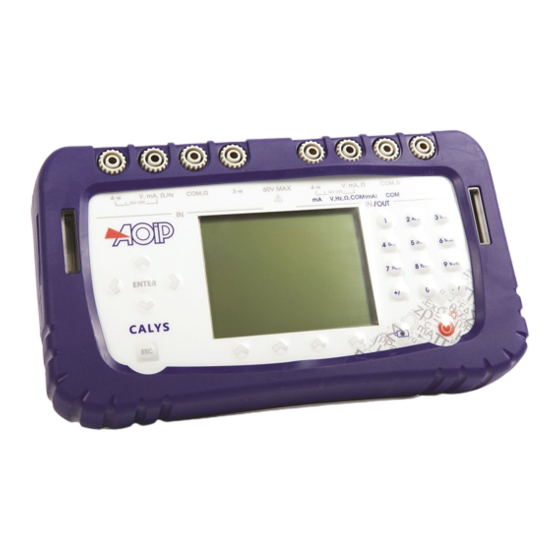
Vue générale de l’appareil Gaine Le CALYS 150 est livré avec une gaine en caoutchouc montée sur le boîtier. La gaine permet de protéger l’appareil des chocs mécaniques et d’assurer une étanchéité IP54 au niveau des ouvertures latérales qui hébergent les connecteurs (interface USB, prises chargeur et capteur de pression).
-
Page 10: Bornes De Raccordement
0. Les 8 bornes du CALYS 150 sont « push & lock ». Elles acceptent les fiches bananes 4 mm, les cordons de sécurité 4 mm, les fils nus, les cosses à fourche et les connecteurs miniatures pour thermocouples.
-
Page 11: Écran
Matériel Écran Le CALYS 150 est doté d’un afficheur LCD graphique avec un rétro-éclairage à LED blanches. La résolution de l’afficheur est de 240 x 320 pixels. Pendant le fonctionnement de l’appareil, l’écran comporte : Une fenêtre destinée à la visualisation et à la programmation des paramètres de la fonction «mesure» (IN). Se reporter au paragraphe B.2.
-
Page 12
CALYS 150 GENERALITES Le navigateur : Une touche d’annulation : Une touche de Marche/arrêt de l’appareil et d’allumage/extinction du rétro-éclairage: Un appui court démarre l’appareil. Pendant le fonctionnement un appui court met en marche ou éteint l’éclairage. Un appui long de 2 secondes arrête l’appareil. Un appui de 6 secondes « réinitialise » l’appareil en cas de blocage. -
Page 13: Batteries Et Chargeur
Batteries et chargeur Précautions à prendre si la charge batterie est faible: A la réception de votre CALYS 150, il est possible que la charge des batteries ne soit pas suffisante pour un fonctionnement optimal voire même pour un démarrage de l’appareil.
-
Page 14: Logiciel
A.3 Logiciel Le logiciel firmware du CALYS 150 est stocké dans une mémoire flash. Par suite, il est relativement facile de faire une mise à jour du firmware quand une nouvelle version est disponible. Se reporter au paragraphe A.5.1 pour des informations détaillées sur la mise à…
-
Page 15
Logiciel L’interface dans les boites de dialogues est intuitive. Elle est gérée par les touches de fonction et celles de navigation. La touche de tabulation permet de sélectionner l’élément suivant dans un ensemble d’éléments constituant la boite de dialogue. Par exemple, pour sélectionner le champ « Type d’échelle » sur l’écran suivant il faut appuyer sur la touche une fois. -
Page 16
CALYS 150 GENERALITES Pendant le fonctionnement du CALYS 150 plusieurs symboles sont affichés pour faciliter la sélection et l’indication des fonctions en cours. Ces symboles sont résumés dans le tableau suivant : Symbole Description Touches de fonction Touche de tabulation Ouvrir une liste déroulante… -
Page 17: Directives Ce
Directives CE A.4 Directives CE Conformité aux directives en vigueur L’appareil est conforme aux directives en vigueur : — Directive sécurité 2006/95/CE avec la norme EN611010-1 — Directive CEM 2004/108/CE avec la norme EN61326-1 — Directive Radio 1999/5/CE avec les normes EN300-328 et EN301-489 La présente notice d’utilisation contient des textes d’information et d’avertissement qui doivent être respectés par l’utilisateur pour assurer sa protection contre les dangers du courant électrique, assurer un fonctionnement sûr de l’appareil, et le préserver contre toute fausse manœuvre pouvant l’endommager ou détériorer sa sécurité…
-
Page 18: Exécution Des Mesures
CALYS 150 GENERALITES Exécution des mesures Les cordons et fils de mesure doivent être en bon état et devront être changés si leur isolement apparaît défectueux (isolant coupé, brûlé, …). Lorsque l’appareil est connecté aux circuits de mesure, des bornes peuvent être dangereuses. Aussi, faut-il éviter de poser les mains à…
-
Page 19: Services
être effectués par un personnel qualifié, bien averti des risques que cela implique. Mise à jour logiciel La mise à jour logiciel se fait par le programme UPG32 disponible sur site Internet www.aoip.com. Pour connaître la version du firmware installé dans votre appareil utiliser le menu Menu propos.
-
Page 20: Recalibration
Soit retourner l’appareil à l’adresse indiquée au début de ce guide pour vérification et ajustage. Il est possible d’effectuer un ajustage du CALYS 150 en utilisation un instrument dont la précision est meilleure que 50 ppm. Pour ajuster l’appareil utiliser le menu…
-
Page 21: Nettoyage
Services Pour ajuster le CALYS 150 utiliser la touche de fonction REGLAGE. Effectuer les opérations de réglage dans l’ordre suivant : Mesure V1 : faire tous les calibres Mesure V2 : faire tous les calibres Offsets Ohms Auto-Ajustage Emission V2 Pour chaque type d’ajustage sélectionner la fonction à…
-
Page 22: Prise En Main
Pour démarrer l’appareil appuyer sur la touche de Marche / arrêt pendant une seconde. Après l’apparition du logo AOIP puis d’une fenêtre indiquant le test des EEPROM, un écran semblable à celui doit apparaître. B.2 Mesure sur la voie V1 Pour pouvoir changer les fonctions Mesure de la voie V1, il faut qu’un rectangle entoure la fenêtre supérieure de l’écran.
-
Page 23
Mesure sur la voie V1 Une boite de dialogue MENU MESURE s’affiche. Les branchements de la voie V1 en mode mesure se font sur les quatre bornes « IN » situées dans la moitié gauche de l’appareil: NTA47224-300A9 23 / 194… -
Page 24: Mesure De Tension Continue
CALYS 150 PRISE EN MAIN Mesure de tension continue Afficher la boite de dialogue MENU MESURE Sélectionner la fonction de mesure puis le calibre adapté à la mesure à l’aide des touches de fonction et de navigation. Valider par ENTER.
-
Page 25
Mesure sur la voie V1 Dans ce cas, le CALYS 150 alimente un transmetteur passif en 24V et mesure en même temps le courant établi par le transmetteur. Si l’alimentation de la boucle est désactivée le branchement se fait entre les bornes mA et COM. -
Page 26: Mesure De Résistance
CALYS 150 PRISE EN MAIN Le CALYS 150 affiche dans la fenêtre une indication sur la configuration choisie à l’aide des icônes suivantes : : pour indiquer une Alimentation de boucle désactivée : pour indique une Alimentation de boucle activée : pour indique une échelle quadratique…
-
Page 27: Test De Continuité
Valider par ENTER. Le CALYS 150 effectue une mesure de résistance dans ce mode et affiche « ouvert » si la résistance mesurée est supérieure à 1000 Ohm et « fermé » si la résistance mesurée est inférieure à 1000 Ohm.
-
Page 28: Mesure De Fréquence
CALYS 150 PRISE EN MAIN Mesure de fréquence Afficher la boite de dialogue MENU MESURE Sélectionner la « fonction de mesure » Fréquence puis le calibre adapté à la mesure à l’aide des touches de fonction et de navigation. Valider par ENTER.
-
Page 29: Comptage D’impulsion
Mesure sur la voie V1 Comptage d’impulsion Afficher la boite de dialogue MENU MESURE : Sélectionner la « fonction de mesure » Comptage à l’aide des touches de fonction et de navigation. Entrer le temps de comptage à l’aide des touches alphanumériques. Valider par ENTER.
-
Page 30: Mesure Sondes Résistives (Température)
Cu 50 (α = 428) α étant le coefficient de température de la sonde. La détection du schéma de câblage se fait automatiquement par le calibrateur. Si l’on sélectionne Le CALYS 150 affiche un pictogramme représentant le montage utilisé (…
-
Page 31: Mesure Thermocouple (Température)
Coeff. Coeff. B Coeff. Valider par ENTER. La détection du schéma de câblage se fait automatiquement par le calibrateur. Si l’on sélectionne Le CALYS 150 affiche un pictogramme représentant le montage utilisé ( pour 2 fils, pour 3 fils ou 4 fils) pour effectuer la mesure.
-
Page 32: Mesure De Pression
CALYS 150 PRISE EN MAIN Mesure de pression Afficher la boite de dialogue MENU MESURE Sélectionner la « fonction de mesure ».PRESSION Choisir les unités (BAR, PSI, Pa, Atm, Kgcm2, cmHg, mmHg, inHg, mH2O, ftH20, inH2O). Valider par ENTER. Brancher le capteur de pression sur le côté droit de l’appareil (voir chapitre connecteurs latéraux). Dans le cas où…
-
Page 33: Modules Au Protocole Hart
Liaison 4/20 mA avec Connexion modem alimentation HART® boucle et résistance HART® ON Pour configurer le CALYS 150 dans ce mode il faut sélectionner la fonction « HART » à partir du « Menu » : NTA47224-300A9 33 / 194…
-
Page 34
PRISE EN MAIN Un menu de configuration s’affiche alors : En premier, sélectionner si le CALYS 150 alimentera la boucle HART (« On ») ou si celle-ci sera assurée par un autre équipement (« Off »). Pour contrôler un réseau HART, il doit y avoir au moins un maître, mais il ne doit y en avoir qu’un dit « Primaire », les autres étant dit «… -
Page 35
Mesure sur la voie V1 Pour les adresses de « 01 » à « 15 », l’appareil se positionne à courant fixe. Pour l’adresse « 00 », l’appareil se positionne en mode point à point qui permet d’utiliser la boucle de courant dans toute sa dynamique et non pas à courant fixe. Si on ne dispose que d’un seul équipement, entrer «… -
Page 36
Se reporter en début du chapitre pour les explications. B.2.11.2 Déconnexion « Déconnexion » permet de se déconnecter du capteur HART et de revenir au menu initial. Le CALYS 150 revient alors avec la voie V1 configurée sur la fonction 4-20mA, impédance HART activée. 36 / 194 NTA47224-300A9… -
Page 37
Mesure sur la voie V1 B.2.11.3 Configuration L’option « Configurer » du menu HART permet d’accéder à l’ « Identification » de l’équipement sélectionné. Un écran affiche alors les caractéristiques du capteur : Fabricant, Type, Id, version logicielle. On peut configurer le nom qui apparaîtra dans la fenêtre de mesure (Etiquette), changer la date (sous la forme jj mm aaaa), donner un nom de description (c’est celle-ci qui apparaît dans la liste des équipements lors de la scrutation), envoyer un message vers le capteur. -
Page 38
CALYS 150 PRISE EN MAIN Dans le cas de ce capteur de température, on peut changer l’unité « °C » ou « °F », définir les valeurs d’affichage pour 0% et 100%, définir un temps de lissage (en S) ou choisir l’utilisation d’une fonction de transfert (linéaire ou racine carrée). -
Page 39
Mesure sur la voie V1 La « Configuration » de la « Sortie HART » permet d’accéder à l’adressage de l’équipement. On utilise cette configuration pour changer l’adresse de l’équipement connecté (par exemple pour passer au mode point à point dans le cas d’un seul capteur). B.2.11.4 Vérification L’option «… -
Page 40
En mode « Manuel », on définit un courant de consigne (4mA dans l’exemple ci-dessus) et on ajuste ce dernier en appuyant sur la touche F2 (« Ajuster »). En mode Vérification de Boucle de courant en Automatique, le CALYS 150 recherche une procédure programmée correspondant à l’équipement en test. -
Page 41
Mesure sur la voie V1 Une fois créée, appuyer sur la touche F3 pour l’ « Editer ». Les paramètres généraux sont ceux renvoyés par le capteur, ils peuvent être changés. Les consignes peuvent être changées. On peut en retirer ou en supprimer avec les touches F2 à F4. Une fois celles-ci mise en conformité… -
Page 42
CALYS 150 PRISE EN MAIN Une fois la procédure définie, on peut l’ « Exécuter » avec la touche F4, la « Dupliquer » avec la touche F2 ou la modifier (« Editer ») avec la touche F3. Le « B » dans la colonne HART indique qu’il s’agit d’une procédure de vérification de la Boucle. -
Page 43
Mesure sur la voie V1 Le CALYS 150 exécute alors pas à pas les différentes étapes définies pour la vérification. On peut accélérer la procédure en appuyant sur la touche F3 (« Stable ») lorsqu’on juge que la stabilité est satisfaisante. -
Page 44
CALYS 150 PRISE EN MAIN Pour créer une procédure de vérification de la partie détecteur, appuyer sur la touche F1 (« OUI »), sinon annulez en appuyant sur la touche F2 (« NON »). Dans le cas de la création d’une procédure, la lettre « D » dans la colonne HART indique qu’il s’agit d’une procédure de vérification du détecteur. -
Page 45
Mesure sur la voie V1 Possibilité de vérification simultanée du détecteur et de la Boucle de courant. Pour créer une procédure de vérification de la partie détecteur, appuyer sur la touche F1 (« OUI »), sinon annulez en appuyant sur la touche F2 (« NON »). Dans le cas de la création d’une procédure, la lettre «… -
Page 46
CALYS 150 PRISE EN MAIN A partir de la rubrique « HART », « Vérifier », « Définir Procédure » on peut directement éditer les 3 types de procédures de vérification : Boucle, Détecteur, Détecteur + Boucle. Se reporter aux paragraphes adéquats dans les explications ci- dessus. -
Page 47
Mesure sur la voie V1 B.2.11.5 Ajustage Il est possible d’ajuster la Boucle de courant et/ou le Détecteur. Pour ajuster la Boucle de courant, sélectionner « Ajuster », « Boucle de courant » dans le menu « HART ». Editer la valeur du courant selon la consigne souhaitée pour le réglage du zéro. Appuyer sur la touche F2 («… -
Page 48
CALYS 150 PRISE EN MAIN L’ajustement du détecteur n’est pas supporté par tous les équipements HART. Dans le cas d’un capteur supportant cette fonctionnalité l’écran est lié au capteur. 48 / 194 NTA47224-300A9… -
Page 49
Mesure sur la voie V1 B.2.11.6 Etat du dispositif La rubrique « Etat du dispositif » du menu HART permet d’accéder à : l’état du dispositif, l’effacement de l’indication de configuration modifiée et à la réinitialisation du dispositif. Pour accéder à l’Etat du dispositif, choisir les rubrique « Etat du dispositif », Etat du dispositif » dans le menu HART. Un tableau affiche alors certains registres d’état du dispositif : Mauvais fonctionnement du dispositif : indique que l’équipement ne fonctionne pas correctement. -
Page 50
CALYS 150 PRISE EN MAIN Cette rubrique sert à effacer l’indicateur de Configuration modifiée. Valider et attendre la fin du message de dialogue. Comme son nom l’indique, cette rubrique sert à réinitialiser le dispositif comme après une mise sous tension. -
Page 51: Generation / Simulation Ou Mesure Sur La Voie V2
Génération / Simulation ou Mesure sur la voie V2 B.3 Génération / Simulation ou Mesure sur la voie V2 La Voie V2 peut être utilisée en Génération/Simulation ou en Mesure. L’accès à cette voie s’effectue à partir de la touche de fonction F2 (V2).
-
Page 52
CALYS 150 PRISE EN MAIN B.3.1.1 Génération de tension continue Afficher la boite de dialogue CONFIGURATION EMISSION : Sélectionner la fonction d’émission Vdc puis le calibre adapté à la mesure à l’aide des touches de fonction et de navigation. Valider par ENTER. -
Page 53
Génération / Simulation ou Mesure sur la voie V2 Si l’alimentation de la boucle est activée, le CALYS 150 simule un transmetteur passif alimenté par 24V en interne. Si l’alimentation de la boucle est désactivée, le CALYS 150 simule un transmetteur passif alimenté par une source de tension externe. -
Page 54
CALYS 150 PRISE EN MAIN B.3.1.4 Simulation de résistance Afficher la boite de dialogue CONFIGURATION EMISSION Sélectionner la fonction de mesure puis le calibre à l’aide des touches de fonction et de navigation. Sélectionner le courant de mesure (continu ou pulsé) Valider par ENTER. -
Page 55
Génération / Simulation ou Mesure sur la voie V2 B.3.1.5 Simulation de sonde résistive (température) Afficher la boite de dialogue CONFIGURATION EMISSION Sélectionner la « fonction d’émission » puis le « type de sonde » approprié à l’aide des touches de fonction et de navigation. -
Page 56
CALYS 150 PRISE EN MAIN B.3.1.6 Simulation de thermocouple (température) Afficher la boite de dialogue CONFIGURATION EMISSION Sélectionner la « fonction d’émission » puis le « type de couple » approprié à l’aide des touches de fonction et de navigation. -
Page 57
Génération / Simulation ou Mesure sur la voie V2 B.3.1.8 Génération de fréquence Afficher la boite de dialogue CONFIGURATION EMISSION Sélectionner la « Fonction d’émission » Fréquence puis le calibre à l’aide des touches de fonction et de navigation. Sélectionner le « Type de Sortie » Signal. Saisir le rapport cyclique entre 20 et 80%. -
Page 58
CALYS 150 PRISE EN MAIN B.3.1.10 Génération d’impulsions Afficher la boite de dialogue CONFIGURATION EMISSION Sélectionner la « Fonction d’émission » Impuls. (<10Hz) Impuls. (>10Hz) à l’aide des touches de fonction et de navigation. Sélectionner le « Type de Sortie » Signal. -
Page 59: Mode Mesure
C. OPERATIONS AVANCEES C.1 Modes de Simulation Plusieurs modes de fonctionnement pour l’émission sont disponibles dans le CALYS 150 pour faciliter la vérification rapide et la calibration des instruments et des transmetteurs. Pour changer le mode d’émission activer la fenêtre émission à l’aide de la touche de fonction (F2).
-
Page 60: Mode Edition Manuelle
CALYS 150 PRISE EN MAIN Pour accéder aux autres modes sélectionner le menu Mode à l’aide de la touche de fonction F4. Sélectionner un mode d’émission à l’aide des touches Haut/Bas du navigateur et valider par ENTER. Pour quitter un mode d’émission et revenir au mode par défaut appuyer sur la touche ESC.
-
Page 61: Mode Edition Incrémentale
Procédure d’étalonnage Mode Edition incrémentale Lorsque ce mode est activé le pictogramme apparaît dans la fenêtre d’émission. Utiliser les 4 touches du navigateur pour éditer la valeur à émettre. Pour sélectionner un digit utiliser les touches Gauche et Droite du navigateur. Le digit éditable apparaît en affichage inversé…
-
Page 62
CALYS 150 PRISE EN MAIN Dans le cas des valeurs prédéfinies en pourcentage de la pleine échelle le pictogramme apparaît à gauche de la fenêtre d’émission. Le pictogramme indique une mise à l’échelle. Pour visualiser la mise à l’échelle appliquée utiliser dans le Menu la rubrique Mise l’échelle, puis Définir… -
Page 63: Mode Marches D’escalier
Procédure d’étalonnage Mode Marches d’escalier Ce mode permet de programmer une progression incrémentale de la fonction d’émission active. Lorsque ce mode est activé le pictogramme apparaît dans la fenêtre d’émission. La touche de fonction permet de lancer un cycle d’incréments croissants et la touche permet de lancer un cycle d’incréments décroissants.
-
Page 64: Mode Rampe Simple
CALYS 150 PRISE EN MAIN Pendant la génération d’une marche d’escalier une barre de progression indique l’état d’avancement. Les touches de fonction permettent de contrôler la génération : La touche permet d’arrêter à tout moment la génération La touche permet de suspendre la génération La touche permet de commencer ou reprendre la génération…
-
Page 65: Mode Rampe Cyclique
Procédure d’étalonnage Pendant la génération d’une rampe simple une barre de progression indique l’état d’avancement. Les touches de fonction permettent de contrôler la génération : La touche permet d’arrêter à tout moment la génération La touche permet de suspendre la génération La touche permet de commencer ou reprendre la génération Le pictogramme…
-
Page 66
CALYS 150 PRISE EN MAIN Les paramètres d’une rampe cyclique sont : B : amplitude minimale du signal. H : amplitude maximale du signal. Thb : durée de la rampe décroissante. Tbh : durée de la rampe croissante. Th : durée du palier haut. -
Page 67: Mode Synthétiseur
Procédure d’étalonnage Mode synthétiseur La fonction synthétiseur permet : de stocker en mémoire permanente jusqu’à 100 valeurs d’émission, de rappeler et d’émettre manuellement ou automatiquement le contenu de ces mémoires. Lorsque ce mode est activé le pictogramme apparaît dans la fenêtre d’émission. La touche de fonction permet de lancer la génération des valeurs dans l’ordre croissant et la touche permet de…
-
Page 68
CALYS 150 PRISE EN MAIN Pour éditer les points à synthétiser utiliser le menu Menu Synthétiseur… Points…. Utiliser les touches de fonction : pour supprimer un point pour ajouter un point pour éditer un point Utiliser les touches pour émettre les points selon les paramètres définis. -
Page 69: Mode Transmetteur
Procédure d’étalonnage Mode transmetteur Ce mode permet d’émettre une valeur identique à la valeur mesurée. NTA47224-300A9 69 / 194…
-
Page 70: Mise A L ‘ Echelle
CALYS 150 PRISE EN MAIN C.2 Mise à l’échelle La fonction de correction d’échelle effectue les opérations de conversion entre les grandeurs électriques mesurées et les grandeurs physiques converties. Cette opération de linéarisation permet de corriger partiellement les erreurs induites par des systèmes capteurs/convertisseurs non linéaires.
-
Page 71: Mesures Differentielles
Mesures différentielles C.3 Mesures différentielles La fonction mesure relative de l’appareil permet : de programmer une valeur de référence différente de celle de l’appareil (fonction NUL), d’annuler par mesure ou programmation une valeur constante ou parasite (fonction TARE). Lorsqu’une des fonctions de mesures relatives est active, le symbole est affiché…
-
Page 72: Capteurs Etalonnes
CALYS 150 PRISE EN MAIN C.4 Capteurs étalonnés La fonction capteurs étalonnés de l’appareil permet d’utiliser des capteurs dont les coefficients d’étalonnage (de correction) sont pris en compte par l’appareil lors de la mesure. Afficher la boite de dialogue MENU MESURE Sélectionner la fonction…
-
Page 73
Capteurs étalonnés Pour entrer dans le tableau des points d’étalonnage, utiliser la touche Entrer les valeurs et valider. Utiliser les touches suivantes pour continuer le paramétrage du capteur. pour éditer un point déjà édité pour ajouter un point pour supprimer un point Il est possible de saisir de 1 à… -
Page 74
CALYS 150 PRISE EN MAIN Dans le cas particulier où un seul point d’étalonnage est indiqué, le comportement est différent selon que le capteur est un thermocouple ou une résistance thermométrique : Dans le cas d’un thermocouple, la correction est un écart fixe de tension. -
Page 75: Procedure D ‘ Etalonnage
C.5 Procédure d’étalonnage Le CALYS 150 est capable d’établir un rapport d’étalonnage (PV : procès-verbal) à partir d’une procédure pré-établie. Le nombre de procédures pouvant être enregistrées est fonction de la taille de la mémoire disponible et de la taille de chaque procédure (nombre de points de tests).
-
Page 76
CALYS 150 PRISE EN MAIN L’appareil est prévu pour 2 méthodes d’étalonnage : « Par comparaison » ou « Générateur étalon ». Définir votre choix à l’aide de la liste déroulante. Dans les 2 méthodes, choisissez le mode de « Mesure Dispositif » : « Voie 1 » ou « Saisie au clavier »… -
Page 77
Procédure d’étalonnage Si vous avez choisi la « Mesure Référence » par la Voie 2, sélectionner la « Fonction de mesure » et valider par Enter. Si vous avez choisi la « Mesure Dispositif» par la Voie 1, sélectionner la « Fonction de mesure » et valider par Enter. Vous avez la possibilité… -
Page 78
(point 1, Point 2, Point3…Point n, Point n-1…Point 2, Point 1). Temps d’établissement permet de définir en seconde la durée entre l’envoi de la consigne en sortie du CALYS 150 et la mesure réalisée en entrée de ce dernier. -
Page 79
Procédure d’étalonnage Il est possible de paramétrer l’appareil pour qu’il affiche un « Verdict » : « OK » ou « KO » à l’issu de la procédure. Dans ce cas, paramétrer l’écart admissible en pourcentage et en unité (suivant le choix du type de mesure). Après avoir renseigné… -
Page 80
CALYS 150 PRISE EN MAIN Pour exécuter une procédure, sélectionnez-la et appuyer sur la touche F4 (Exécuter) ou la touche Enter. Après avoir renseigné les champs, lancer l’exécution en appuyant sur la touche F3 (Exécuter). Dans le cas où la procédure est exécutée manuellement, l’utilisateur devra valider un à un tous les ponts d’étalonnage. -
Page 81
Procédure d’étalonnage Appuyer sur la touche de fonction F1 pour enregistrer le PV. Pour afficher les PV, sélectionner la procédure voulue puis appuyer sur la touche de fonction F2 (PVs). Sélectionner dans la liste le PV à visualiser puis valider en appuyant sur la touche de fonction F1 (Afficher). NTA47224-300A9 81 / 194… -
Page 82: Memorisation Des Acquisitions En Cours
C.6 Mémorisation des acquisitions en cours Le CALYS 150 est capable de mémoriser 10 000 valeurs en une ou plusieurs salves d’acquisition. Utiliser si nécessaire la touche F2 pour activer la fenêtre ‘V1’ et afficher la barre du menu Mesure.
-
Page 83
Mémorisation des acquisitions en cours STOP : Arrête la mémorisation en cours. PARAMETRES : Permet de définir : La taille de la salve (max 10 000 valeurs), la période d’échantillonnage de 0,5 S à 30 Min, et le type de trigger (Aucun, niveau bas, niveau haut). La possibilité… -
Page 84
CALYS 150 PRISE EN MAIN En appuyant sur les touches de navigation gauche ou droite il est possible de déplacer le curseur et de lire la valeur en abscisse et ordonnée. Il est possible à ce niveau de redéfinir les marqueurs afin de faire un zoom entre ces deux nouveaux points : Dans le champ X, entrer une valeur qui sera la valeur basse du marqueur (X1), valider par ENTER et appuyer sur la touche de fonction F2 (X 1). -
Page 85
Mémorisation des acquisitions en cours Nouvelle salve libre : Permet de débuter une nouvelle salve. Dans le cas où une salve est en cours, il sera demandé de sauvegarder celle-ci. Gestion des salves : Permet de visualiser toutes les salves enregistrées. Il est possible, à ce niveau, de renommer une salve ou d’effacer une ou toutes les salves. -
Page 86: Configurations
Pour rappeler une configuration en mémoire utiliser le menu Menu Fichier Ouvrir… Utiliser les touches de navigation pour sélectionner une configuration. Valider par ENTER. Lors du chargement d’une configuration sauvegardé, le CALYS 150 se met en mode Edition manuelle en émission. 86 / 194 NTA47224-300A9…
-
Page 87
Configurations Pour effacer les configurations du CALYS 150 se reporter au paragraphe A.5.2 pour entrer dans mode Maintenance. Utiliser la touche de fonction Init EEP afin de mettre à zéro les configurations de l’appareil. NTA47224-300A9 87 / 194… -
Page 88: Parametrage
CALYS 150. Réglage de contraste Utiliser les touches de navigation Droit et Gauche pour ajuster le contraste de l’afficheur. Le CALYS 150 sauvegarde le réglage effectué dans sa mémoire non volatile. Il utilise le réglage effectué à chaque démarrage de l’appareil.
-
Page 89: Préférences
Paramétrage Préférences Pour afficher la boite de dialogue Préférences utiliser le menu Configuration Setup. Préférences…. Les paramètres réglables sont : Filtrage : Permet de moyenner les mesures avant l’affichage. Quand le filtrage est désactivé le temps d’intégration des mesures est de 0,5 seconde. Résolution : Permet de régler la résolution des mesures lors de l’affichage.
-
Page 90: Configuration De Linterface Bluetooth
CALYS 150 PRISE EN MAIN C.9 Configuration de l’interface Bluetooth® La mise en fonctionnement du module Bluetooth® s’effectue à partir de la touche F1 MENU Bluetooth Il est possible de donner un nom à l’appareil qui sera connecté à un réseau Bluetooth® à partir de la touche F1…
-
Page 91: Specifications Techniques
Affichage avec mise à l’échelle linéaire ou quadratique Ces spécifications sont données pour les configurations suivantes :- — CALYS 150 mode actif (+24 V ON) Mesureur mode passif (+24 V OFF). — CALYS 150 mode passif (+24 V OFF) …
-
Page 92: Résistance
CALYS 150 SPECIFICATIONS TECHNIQUES Résistance Calibre Gamme de mesure Résolution Précision / 1 an Remarques 400 Ω 0 Ω à 400 Ω 1 mΩ 0,006% L + 8 mΩ Mesure 4 fils 3600 Ω 0 Ω à 3600 Ω 10 mΩ…
-
Page 93: Température Par Couples Thermoélectriques
Fonction mesure (Voie 1 et Voie 2) Température par couples thermoélectriques Type de capteurs : — Normalisés selon CEI 584-1/1995 (Couples K, T, J, E, S, B, N). — Selon Din 43710 (couples U et L). — Selon la table d’ENGELHARD (couple Platine) — Selon la norme ASTM E 1751-00 (couple G) — Selon la norme ASTM E 988-96 (couple D W3Re/W25Re ;…
-
Page 94: Température Par Sondes À Résistance
CALYS 150 SPECIFICATIONS TECHNIQUES La précision est garantie pour une jonction de référence (JR) à 0°C. Avec utilisation de la JR interne (sauf couple B) ajouter une incertitude supplémentaire de 0,2°C à 0°C. Pour les autres températures, il y a lieu tenir compte de la sensibilité du thermocouple à la température (T) considérée, soit une incertitude supplémentaire de 0,2°C*S(0°C)/S(T).
-
Page 95: Fréquence Et Comptage
Fonction mesure (Voie 1 et Voie 2) Fréquence et comptage Calibre Résolution Gamme de mesure Précision / 1 an Remarques 10 kHz 0,01 Hz 1 Hz à 10 KHz 0,005% L + 5 mHz Vin min = 1 V 100 kHz 0,1 Hz 10 Hz à…
-
Page 96: Fonction » Emission / Simulation
Coefficient de température < (6 ppm L + 0.5 ppm Cal)/°C de 0°C à +18°C et de +28°C à +50°C. Ces spécifications sont données pour les configurations suivantes : — CALYS 150 mode actif (+24 V ON) Mesureur mode passif (+24 V OFF) — CALYS 150 mode passif (+24 V OFF) …
-
Page 97: Température Par Couples Thermoélectriques
Fonction «Emission / Simulation» Température par couples thermoélectriques Type de capteurs : — Normalisés selon CEI 584-1/1995 (Couples K, T, J, E, S, B, N). — Selon Din 43710 (couples U et L). — Selon la table d’ENGELHARD (couple Platine) — Selon la norme ASTM E 1751-00 (couple G) — Selon la norme ASTM E 988-96 (couple D W3Re/W25Re ;…
-
Page 98: Température Par Sondes À Résistance
CALYS 150 SPECIFICATIONS TECHNIQUES Température par sondes à résistance Type de sondes : Pt 10 ohm, 50 ohm, 100 ohm, 200 ohm, 500 ohm , 1 000 ohm avec α = 3851 selon la publication CEI 751/1995 Pt 100 ohm avec α = 3916 selon la publication JIS C 1604/1989 Pt 100 ohm avec α…
-
Page 99: Fréquence Et Impulsion
Fonction «Emission / Simulation» Fréquence et impulsion Calibre Résolution Gamme Précision / 1 an Remarques 1 000 Hz 0,01 Hz 0,01 Hz à 1 000 KHz 0,005% L + 5 mHz 100 kHz 1 Hz 1 Hz à 100 KHz 0,005% L + 5 mHz Coefficient de température <…
-
Page 100
CALYS 150 Multifunction Process Calibrator Instruction manual 100 / 194 NTA47224-300A9… -
Page 101
Parts, repairs to the product and service are guaranteed for a period of 90 days. This guarantee only applies to the original purchaser or the end user if he is a client of an AOIP S.A.S approved distributor and does not cover fuses, interchangeable batteries/cells nor any product which, in the opinion of AOIP S.A.S, has been badly… -
Page 102
CALYS 150 TABLE OF CONTENTS Table of contents GENERAL …………………………..104 ………………………….. 104 NTRODUCTION About this guide …………………………105 Unpacking …………………………..105 Returning …………………………..105 …………………………..106 ATERIAL General view of the unit ……………………….. 106 Sheath …………………………..106 Connection terminals ……………………….107 Side connectors ………………………… -
Page 103
CALYS 150 TABLE OF CONTENTS ADVANCED OPERATION ……………………….157 …………………………157 IMULATION ODES Manual Edit Mode ……………………….157 Incremental Edit Mode ………………………. 158 Predefined Settings Mode ……………………..158 Staircase mode …………………………. 160 Simple Ramp Mode ……………………….161 Cyclic Ramp Mode ……………………….162 Synthesizer Mode ………………………. -
Page 104: General
A.1 Introduction The CALYS 150 is hand-held, highly accurate multifunction calibrator used to measure and transmit simultaneously over 2 insulated channels or to measure over 2 input channels (differential measurements or comparative measurements). It is specially designed for calibration and maintenance and can measure and simulate physical and electrical quantities, either on site or in the laboratory.
-
Page 105: About This Guide
Part D contains the technical specifications of the CALYS 150. Unpacking All CALYS 150 units are mechanically and electrically checked before delivery. The necessary precautions have been taken to ensure that they reach the user undamaged. However, it is a good idea to make a brief check for any damage that may have occurred during transportation. If this is the case, make an immediate claim against the carrier.
-
Page 106: Material
Sheath The CALYS 150 is delivered with a rubber sheath fitted to the case. The sheath protects the unit from mechanical shocks and has side openings for the USB interface connector and the charger connector. The protection level is IP54.
-
Page 107: Connection Terminals
Four terminals for connection when «transmit/simulate measurement» function (OUT/IN) from channel 2 (V2) is used. Refer to paragraph The 8 terminals of the CALYS 150 are of the “push & lock” type. They accept 4 mm banana plugs, bare wires, spade terminals and miniature connectors for thermocouples.
-
Page 108: Screen
CALYS 150 GENERAL Screen The CALYS 150 is fitted with an LCD graphical display which is backlit with white LEDs. The resolution of the display is 240 x 320 pixels. When the unit is in use, the screen comprises: A window displaying the programming of the «measurement» function parameters (IN). Refer to paragraph B.2.
-
Page 109
Material A navigator: A cancel key: A Start/stop key for the unit and back-lighting on/off key: A short push switches the unit on. During operation, a short push switches the back-lighting on or off. A long push of 2 seconds switches the unit off. A long push of 6 seconds resets the unit in case of lock. 12 alphanumeric keys for programming the parameters. -
Page 110: Batteries And Charger
Date and time are saved when the instruments is switched off on a 3 V Lithium battery (CR1225 type). Stand The stand gives a good angle of view when the CALYS 150 is placed on a desk. Unfold the stand on the back of the unit and place the CALYS 150 on a desk as shown below.
-
Page 111: Software
Software A.3 Software The firmware of the CALYS 150 is stored in flash memory. It is therefore easy to update the firmware when a new version is available. Refer to paragraph A.5.1 for detailed information on updating the firmware. User Interface The basic items forming the user interface are shown in the diagram below: The “on-line help”…
-
Page 112
CALYS 150 GENERAL The dialogue box interface is intuitive. It is managed by the function and navigation keys. The tabulation key is used to select the next item from all the items in the dialogue box. For example, to select the “Type of scale”… -
Page 113
Software During operation of the CALYS 150, several symbols are displayed to simplify selection and indication of the current functions. These symbols are shown in the table below: Symbol Description Function keys Tabulation key Open a drop-down list Close a drop-down list… -
Page 114: Safety
CALYS 150 GENERAL A.4 Safety Compliance with safety standards The unit complies with applicable standards: — Safety directive 2006/95/CE with standard EN611010-1 — Directive CEM 2004/108/CE with standard EN61326-1 — Radio directive 1999/5/CE with standards EN300-328 and EN301-489 This user manual contains information and warnings which must be observed in order to protect the user against the hazards of electric current, to ensure the safe operation of the device and to protect it against any mishandling which could damage or compromise the safety of use of the device.
-
Page 115: Making Measurements
Safety Making measurements Measuring wires and leads must be in good condition and must be replaced if their insulation appears defective (insulation cut, burned, etc.). When the unit is connected to the measurement circuit, the terminals may be dangerous. Also, never place your hands near a terminal, whether in use or not.
-
Page 116: Service
Software updates The software is updated by the UPG32 program available on the Web-site, www.aoip.com. To find out which version of firmware is installed in your unit, use the Menu About menu.
-
Page 117
Service Confirm the update by pressing “OK” and wait for the firmware to load into the unit. NTA47224-300A9 117 / 194… -
Page 118: Recalibration
Or return the unit to the address shown at the start of this guide for checking and adjustment. It is possible to adjust the CALYS 150 using an instrument whose accuracy is better than 50 ppm. To adjust the unit, select the Menu Maintenance menu, then enter the password 9456.
-
Page 119: Cleaning
Cleaning If the CALYS 150 needs cleaning, use a tissue soaked in a non-solvent cleaning solution. Switch off the unit and wipe the sheath and keyboard if necessary. If any liquid enters the unit it may cause irreparable damage.
-
Page 120: Getting Started
LED goes off. To start instrument, press On / Off key for one second. After AOIP logo is displayed followed by a window showing EEPROM testing, a screen similar to the one below should appear. 120 / 194…
-
Page 121: Measurement On Channel V1
Measurement on channel V1 B.2 Measurement on channel V1 To change the Measurement functions from channel V1, a rectangle should surround the top window on the screen. If it is not the case, select channel by activating the measurement window with function key F2 (V1). To choose a measurement function, press key F1 (Menu).
-
Page 122: Measuring Dc Voltage
CALYS 150 GETTING STARTED In measurement mode, channel V1 is connected to the four «IN» terminals located on the left half of the unit: Measuring DC voltage Display the MEASUREMENT MENU dialogue box: Select the Vdc measurement function then the correct measurement range using the function and navigation keys.
-
Page 123: Measuring Current
If loop power supply is on, the connection is made between terminals 4-w and mA. In this case, the CALYS 150 supplies a passive transmitter with 24 V and at the same time measures the current established by the transmitter.
-
Page 124
In the case of the 4-20 mA range, the scale curve is as follows: x (mA) The CALYS 150 displays in the window details of the selected configuration using the following icons: : to show loop power supply off : to show loop power supply on : to show square law scale : to show HART compatibility. -
Page 125: Measuring Resistance
To carry out a correct resistance measurement with 3 wires, the 3 conductors used must be: of the same length, of the same diameter, of the same type of metal. The CALYS 150 displays an icon showing the connections used ( for 2 wire, for 3 wire or 4 wire) to make the measurement.
-
Page 126: Continuity Test
Select the Continuity measurement function using the function and navigation keys. Confirm with ENTER. The CALYS 150 makes a resistance measurement in this mode and displays “open” if the resistance measured is greater than 1000 Ohm and “closed” if the resistance measured is less than 1000 Ohm.
-
Page 127: Pulse Counting
Measurement on channel V1 Pulse counting Display the MEASUREMENT MENU dialogue box: Select the Counting measurement function, then the “type of input” Signal or Hard Contact using the function and navigation keys. Enter the counting time using the alphanumeric keys. Confirm with ENTER.
-
Page 128: Resistive Temperature Probes (Temperature)
Cu 50 (α = 428) Cu50 α is the temperature coefficient of the probe. Wiring diagram is automatically detected by the calibrator. The CALYS 150 displays an icon showing the connections used for 2 wires, for 3 wires or for 4 wires) to carry out the measurement. The wiring arrangement is automatically detected by the calibrator.
-
Page 129: Measurement By Thermocouple (Temperature)
Enter coefficients corresponding to thermistor Coeff. A, Coeff. B and Coeff. C. Confirm with ENTER. Wiring diagram is automatically detected by the calibrator. The CALYS 150 displays an icon showing the connection used to carry out measurement ( for 2 wires, for 3 wires or for 4 wires).
-
Page 130: Pressure Measurement
CALYS 150 GETTING STARTED Pressure measurement Open the MEASUREMENT MENU dialog box, Select the Pressure measurement function. Select the unit (BAR, PSI, Pa, Atm, Kgcm2, cmHg, mmHg, inHgftH2O, inH2O). Press ENTER. Connect the pressure sensor on the right-hand side of the unit (see chapter, side connectors). If this is not connected or is defective, an error message will be displayed.
-
Page 131: Modules With Hart® Protocol
The CALYS 150 with related HART® module (ACL500) is used to carry out all of these operations. To use the CALYS 150 in HART mode, the unit must be connected to the current loop (across 24 V Out terminals from channel V1) and be provided with the specific ACL500 modem (connected to the unit’s side).
-
Page 132
The «Number of repeats» parameter is also specific to this protocol, it may be set to a value from 00 to 05. By default it is set to 02. Enter device address from 00 to 15 or press F4 key (Scan) to scan for connected devices. The CALYS 150 will then pool the 15 network addresses to find out which replies and at which address. -
Page 133
Measurement on channel V1 Typical scan with only one device connected at address 00. When selecting one of the addresses from a detected device, display is the same as if a valid address had been directly entered: Display depends on the type of sensor, in this case, it is a temperature sensor in point-to-point mode at address 0. Pressing F1 key («HART») displays a specific menu: NTA47224-300A9 133 / 194… -
Page 134
CALYS 150 GETTING STARTED B.2.11.1 Connection «Connection» is used to connect to a selected device. The same initial menu as when selecting the «HART» function is displayed, just select the address of the sensor to be used. See details at the beginning of the chapter. -
Page 135
Measurement on channel V1 B.2.11.2 Disconnection «Disconnection» is used to disconnect from HART sensor and return to initial menu. The CALYS 150 returns with channel V1 configured to the 4-20mA function, HART impedance enabled. NTA47224-300A9 135 / 194… -
Page 136
CALYS 150 GETTING STARTED B.2.11.3 Configuration The «Configure» option from the HART menu is used to access the «Identification» screen from selected device. A screen displays sensor characteristics: Manufacturer, Type, ID and software version. In the measurement window (Label), you may configure the name, change the date (in the form of dd mm yyyy) enter a descriptor (displayed in the list of devices when scanning), send a message to the sensor. -
Page 137
Measurement on channel V1 For this temperature sensor, you may change units «°C» or «°F», set display values for 0% and 100%, set a smoothing time (in s) or select a transfer function (linear or square root). Press «Transmit» (F2 key) to send the new parameters to the device for them to be taken into account. The detector configuration option is not supported by every sensor. -
Page 138
CALYS 150 GETTING STARTED «Configuration» from «HART output» is used to access configuration of the device address. This configuration is used edit the connected device address (e.g., to switch to point-to-point mode in the event of a single sensor). B.2.11.4 Verification The «Verify»… -
Page 139
In «Manual» mode, a setpoint current is defined (4 mA in the example above) and adjusted by pressing the F2 key («Adjust»). In automatic verify current loop mode, the CALYS 150 looks for a programmed procedure matching the device under test. -
Page 140
CALYS 150 GETTING STARTED Once created, press the F3 key to «Edit» it. General parameters are those returned by the sensor, these may be edited. Setpoints may be edited. These may be removed or deleted with keys F2 to F4. -
Page 141
Measurement on channel V1 Once the procedure defined, it may be «Run» with the F4 key, «Duplicated» with the F2 key or «Edited» with the F3 key. «B» in the HART column indicates that it is a verify loop procedure. When running, you may enter the device serial number, name of the operator and a comment. -
Page 142
CALYS 150 GETTING STARTED The CALYS 150 then runs the various steps defined for verification step-by-step. The procedure may be accelerated by pressing the F3 key («Stable») when stability is deemed satisfactory. At the end of the verification procedure, the results may be «Saved» with the F1 key or exited with the «ENT» key. -
Page 143
Measurement on channel V1 To create a verification procedure for the detector part, press the F1 key («YES») or else cancel by pressing the F2 key («NO»). When a procedure is created, the letter «D» in the HART column indicates that it is a verify detector procedure. Edit procedure to complete creation. -
Page 144
CALYS 150 GETTING STARTED To create a verification procedure for the detector part, press the F1 key («YES») or else cancel by pressing the F2 key («NO»). When a procedure is created, the letter «H» in the HART column indicates that it is a verify detector procedure for the detector and current loop. -
Page 145
Measurement on channel V1 Edit current value according to required setpoint for zero setting. Press the F2 key («Adjust» when device is ready. Then press the F3 key («Continue») to move to the next point. Edit current value according to required setpoint for gain adjustment. Press the F2 key («Adjust») when device is ready. -
Page 146
CALYS 150 GETTING STARTED When a sensor supports this function, the screen is linked to the sensor. B.2.11.6 Device status The «Device status» item from the HART menu is used to access the following: Device status, Clear modified configuration indication and Reset device. -
Page 147
Measurement on channel V1 This item is used to clear the Modified configuration flag. Confirm and wait for end of message to be displayed in dialogue box. This item is self-explanatory, it is used to reset a device as after a modified power-up. Confirm and wait for end of message to be displayed in dialogue box. -
Page 148: Generation / Simulation Or Measurement On Channel V2
CALYS 150 GETTING STARTED B.3 Generation / Simulation or Measurement on Channel V2 Channel V2 may be used as a Generation/Simulation or Measurement Channel. This channel is accessed with the F2 function key (V2). Pressing this button activates the transmission/simulation window: the lower window in the display is then marked by a rectangular border.
-
Page 149
Linear or square law Linear or square law Connection is made between the mA and COM terminals. If the loop power supply is on, the CALYS 150 simulates a passive transmitter supplied with 24 V externally. NTA47224-300A9 149 / 194… -
Page 150
CALYS 150 GETTING STARTED If the loop power supply is off, the CALYS 150 simulates a passive transmitter supplied with 24 V externally. When the square law scale is selected, it must be activated by using the Menu Set to scale menus. Once “set to scale”… -
Page 151
Generation / Simulation or Measurement on Channel V2 B.3.1.3 Resistance simulation Display the TRANSMISSION CONFIGURATION dialogue box: Select the Ohm measurement function, Select the Idc measurement function, then the range using the function and navigation keys. Select measurement current (direct or pulsed) Confirm with ENTER. -
Page 152
CALYS 150 GETTING STARTED B.3.1.4 Resistive probe simulation (temperature) Display the TRANSMISSION CONFIGURATION dialogue box: Select the Rt transmission function, then the appropriate “type of probe”, and range using the function and navigation keys. Select the display unit Select measurement current (direct or pulsed) Confirm with ENTER. -
Page 153
Generation / Simulation or Measurement on Channel V2 B.3.1.5 Thermocouple simulation (temperature) Display the TRANSMISSION CONFIGURATION dialogue box: Select the Tc transmission function, then the appropriate “type of thermocouple”, using the function and navigation keys. Select the display unit Select the type of cold junction compensation (CJC) used. Enter the temperature of the CJC in the case of a programmed CJC. -
Page 154
CALYS 150 GETTING STARTED B.3.1.7 Frequency generation Display the TRANSMISSION CONFIGURATION dialogue box: Select the Frequency transmission function, then the range using the function and navigation keys. Select the Signal “Output type”. Enter cyclic ratio between 20 and 80% Enter the amplitude of the signal between 0 and 20 V. -
Page 155
Generation / Simulation or Measurement on Channel V2 B.3.1.9 Pulse generation Display the TRANSMISSION CONFIGURATION dialogue box: Select the Pulse transmission function, then the range using the function and navigation keys. Select the “Type of Output” Signal. Enter the amplitude of the signal between 0 and 20 V. Confirm with ENTER. -
Page 156: Measurement Mode
CALYS 150 GETTING STARTED During pulse generation, a progress bar indicates the state of progress. The function keys can be used to control generation: key stops generation at any time key suspends generation key commences or resumes generation icon in the transmission window indicates suspended generation.
-
Page 157: Advanced Operation
C. ADVANCED OPERATION C.1 Simulation Modes Several transmission modes are available in the CALYS 150 to facilitate rapid checking and calibration of instruments and transmitters. To change the transmission mode, open the transmission window using the OUT function key (F2).
-
Page 158: Incremental Edit Mode
CALYS 150 ADVANCED OPERATION Incremental Edit Mode When this mode is active, the icon appears in the transmission window. Use the 4 navigator keys to edit the value to be transmitted. To select a digit, use the Left and Right keys of the navigator.
-
Page 159
Simulation Modes In the case of values predefined as a percentage of full scale, the icon appears on the left hand side of the transmission window. icon indicates setting to scale. To view applied scaling, use Scaling, and Define items from Menu. Value pairs may be edited. -
Page 160: Staircase Mode
CALYS 150 ADVANCED OPERATION Staircase mode This mode is used to program an incremental progression of the active transmission function. When this mode is active, the icon appears in the transmission window. function key launches a cycle of increasing increments and the function key launches a cycle of decreasing increments.
-
Page 161: Simple Ramp Mode
Simulation Modes Simple Ramp Mode The simple ramp generation function is used to program a linear variation in one direction (increasing or decreasing) of the active transmission function. When this mode is active, the icon appears ion the transmission window. key is used to launch an increasing ramp and the function key is used to launch a decreasing ramp.
-
Page 162: Cyclic Ramp Mode
CALYS 150 ADVANCED OPERATION Cyclic Ramp Mode The cyclic ramp generation function is used to program a first linear variation in a direction (increasing or decreasing) followed by a first step and then a second linear variation in a direction opposite to the first variation followed by a second step.
-
Page 163: Synthesizer Mode
Simulation Modes During generation of a cyclic ramp, a progress bar indicates the state of progress. The function keys are used to control generation: key stops generation at any time key suspends generation key commences or resumes generation icon in the transmission window indicates suspended generation. Synthesizer Mode The synthesizer function is used: to store up to 100 transmission values in permanent memory,…
-
Page 164
CALYS 150 ADVANCED OPERATION To edit the points to be synthesized, use the Menu Synthesizer… Points…. Use the function keys: to cancel a point to add a point to edit a point Use the keys to transmit points according to the parameters defined. -
Page 165: Transmitter Mode
Simulation Modes Transmitter Mode This mode is used to transmit a value identical to the measured value. NTA47224-300A9 165 / 194…
-
Page 166: Scaling
CALYS 150 ADVANCED OPERATION C.2 Scaling The scale correction function performs a conversion between the electrical quantities measured and the physical quantities converted. This linearization is used partially to correct errors induced by non-linear sensor/converter systems. The Set to scale function is used to define up to 10 segments of a straight line, or 10 points, in order to approach a non- linear response curve as closely as possible and to perform scale corrections for each segment.
-
Page 167: Differential Measurements
Differential measurements C.3 Differential measurements The relative measurement function of the unit is used: to program a reference value other than that of the unit (ZERO function), to cancel by measurement or programming a constant or interfering value (TARE function). When one of the relative measurement functions is active, the symbol is displayed on the screen in the measurement window.
-
Page 168: Calibrated Sensors
CALYS 150 ADVANCED OPERATION C.4 Calibrated sensors The unit’s calibrated sensors function makes it possible to use sensors of which the calibration (correction) factors can be taken into account by the unit at the time of measurement. Open the MEASUREMENT MENU dialog box, Select the Calibrated Sensors function.
-
Page 169
Calibrated sensors To enter calibration points in the table, use the button. Enter the values and press ENTER. Use the following buttons to continue configuring a sensor: to edit an existing calibration point, to add a calibration point, to delete a calibration point. Between 1 and 4 calibration points can be entered per sensor. -
Page 170: Calibration Procedure
ADVANCED OPERATION C.5 Calibration procedure The CALYS 150 is capabable of creating a calibration report from a pre-defined procedure. The number of procedures that can be recorded depends on the size of the available memory and the size of each procedure (number of test points).
-
Page 171
Calibration procedures For the «Standard generator» calibration method, in the In the «By comparison» method, select «Reference drop-down list, select «Channel 2″ or Other (manual measurement» method: «Channel 2» or «Keyboard entry». control) If «Standard generator» via channel 2 is selected, select For the «By comparison»… -
Page 172
CALYS 150 ADVANCED OPERATION You may apply scaling to a device: select «ON» and set parameters. Press key F2 (Points) to set calibration points. Use the following buttons to define the points. to edit an existing calibration point, to add a calibration point, to delete a calibration point. -
Page 173
Calibration procedures The settling time field can be used to define the time, in seconds, between sending the setting from the output of the CALYS 150 and making the measurement at its input. The unit may be set to display a «Verdict»: «OK» or «KO» at the end of the procedure. In this case, set permissible deviation in percent and units (according to the type of measurement). -
Page 174
CALYS 150 ADVANCED OPERATION To run a procedure, select it and press the F4 key (Run) or Enter key. After completing the fields, start execution by pressing F3 (Execute). Where the procedure is executed manually, the user will have to confirm the calibration points one by one. -
Page 175
Calibration procedures If the transmission mode has been defined as One-Way or Two-Way, the procedure is executed automatically. Press the function button, F1, to store the calibration report. To display the calibration reports, select the desired procedure and press the function button, F2 (Reports). From the list, select the report to be viewed and press the function button, F1 (View). -
Page 176: Storing The Current Acquisitions
ADVANCED OPERATION C.6 Storing the current acquisitions The CALYS 150 is capable of storing 10,000 values in one or more acquisition bursts. If necessary, use the F2 button to open the ‘IN’ window and display the Measurement menu bar. Press F1 key to open Menu Select the Menu function then Memory.
-
Page 177
Storing the current acquisitions STOP: Stops the current storage operation. PARAMETERS This can be used to define: the burst size (10,000 values max.), the sampling period, from 0.5 sec. to 30 min, and the type of trigger (none, low level, high level). the same parameters may be selected for both channels (V1 and V2), the same commands common to both channels (V1 and V2) may be selected Block size (2,500 measurements) -
Page 178
CALYS 150 ADVANCED OPERATION To display all the values in memory, press the function button F1 (Global). The left and right arrow buttons can be pressed to move the cursor and read off the abscissa and ordinate values. At this level, the markers can be redefined in order to zoom in between these two new points: in the X field, enter a low value for the marker (X1), press ENTER and then press the function button, F2 (X 1), in the X field, enter a high value for the marker (X2), press ENTER and then press the function button, F3 (X 2). -
Page 179
Storing the current acquisitions New burst: starts a new burst. If a burst is running, the user will be asked if this should be saved. Burst management: can be used to view all bursts in memory. At this level, a burst can be renamed or one or more bursts can be deleted. Statistics: shows the number of bursts in memory, the number of free bytes and the number of measurements that can be saved. -
Page 180: Configurations
ADVANCED OPERATION C.7 Configurations A configuration is the state of the CALYS 150 at a given moment. The state of the unit includes: The current functions and ranges for measurement and simulation, The parameters of all the transmission modes (staircase, ramp, synthesizer, etc.), The scale corrections applied, All the preferences defined in paragraph 0.
-
Page 181
Configurations To erase the configurations of the CALYS 150, refer to paragraph A.5.2 to enter the Maintenance mode. Use the Init EEP function key to reset the configurations of the unit to zero. NTA47224-300A9 181 / 194… -
Page 182: Setting Parameters
150. Adjustment of contrast Use the Right and Left navigation keys to adjust the contrast of the display. The CALYS 150 saves the setting made in its non-volatile memory and uses it each time the unit is switched on. Date and Time To set the date and time, use the Configuration Setup.
-
Page 183: Preferences
Setting parameters Preferences To display the Preferences dialogue box, use the Configuration Setup Preferences… menus. The adjustable parameters are: Filtering: Used to average measurements before display. When filtering is switched off, the integration time for measurements is 0.5 seconds. Resolution: Used to adjust the resolution of the measurements when displayed. There are three possible choices: HIGH: displays measurements with the highest possible resolution.
-
Page 184: Bluetooth® Interface Configuration
CALYS 150 ADVANCED OPERATION C.9 Bluetooth® Interface Configuration The Bluetooth® module is enabled with the F1 key MENU Bluetooth A name may be assigned to a unit connected to a Bluetooth® network with the F1 key MENU Setup Bluetooth Name local.
-
Page 185: Technical Specifications
HART compatibility: input impedance Rin = 280 Ω Linear or square law display scale. These specifications are provided for the following configurations:- — CALYS 150 active mode (+24 V ON) Measurer passive mode (+24 V OFF). — CALYS 150 passive mode (+24 V OFF) …
-
Page 186: Temperature By Thermocouples
CALYS 150 TECHNICAL SPECIFICATIONS Closed circuit for R < 1000 Ω Temperature by thermocouples Sensor types: — In accordance with CEI 584-1/1995 (couples K, T, J, E, S, B, N), — In accordance with Din 43710 (couples U and L), — In accordance with the ENGELHARD table (platinum couple).
-
Page 187: Temperature Using Resistive Probes
Measurement Function (Channel 1 and Channel 2) The precision is guaranteed for a reference junction temperature of 0°C. When using the internal reference junction (except couple B) add an additional uncertainty of 0.2°C at 0°C. For other temperatures, account must be taken of the sensitivity of the thermocouple to the temperature (T) in question, giving an additional uncertainty of 0.2°C * S(0°C)/S(T).
-
Page 188: Frequency And Counting
CALYS 150 TECHNICAL SPECIFICATIONS Frequency and counting Range Resolution Measuring range Accuracy / 1 year Notes 10 kHz 0.01 Hz 1 Hz to 10 KHz 0.005% R + 5 mHZ Vin min = 1 V 100 kHz 0.1 Hz 10 Hz to 100 KHz 0.005% R + 5 mHZ…
-
Page 189: Transmission / Simulation» Function
Temperature coefficient < (6 ppm L + 0.5 ppm Cal)/°C from 0°C to +18°C and from +28°C to +50°C. The above specifications are given for the following configurations: — CALYS 150 active mode (+24 V ON) Passive mode measurer (+24 V OFF).
-
Page 190: Temperature By Thermocouples
CALYS 150 TECHNICAL SPECIFICATIONS Temperature by thermocouples Sensor types: — in accordance with CEI 584-1/1995 (couples K, T, J, E, S, B, N), — in accordance with Din 43710 (couples U and L), — in accordance with the ENGELHARD table (platinum couple).
-
Page 191: Temperature By Resistive Probes
«Transmission / Simulation» Function The precision is guaranteed for a reference junction temperature of 0°C. When using the internal reference junction (except couple B) add an additional uncertainty of 0.2°C at 0°C. For further temperatures, account must be taken of the sensitivity of the thermocouple to the temperature (T) in question, giving an additional uncertainty of 0.2°C * S(0°C)/S(T).
-
Page 192: Frequency And Pulses
CALYS 150 TECHNICAL SPECIFICATIONS Frequency and pulses Range Resolution Range Accuracy / 1 year Notes 1 000 Hz 0.01 Hz 0.01 Hz to 1 000 KHz 0.005% R + 5 mHz 100 kHz 1 Hz 1 Hz to 100 KHz 0.005% R + 5 mHz…
-
Page 193
NTA47224-300A9 December 2018 (French — English) © 2004, 2018 AOIP S.A.S. All rights reserved. Printed in France. All product names are trademarks of their respective companies. NTA47224-300A9 193 / 194… -
Page 194
AOIP SAS ZAC DE L’ORME POMPONNE 50-52 Avenue PAUL LANGEVIN F-91130 RIS-ORANGIS From France: +33 (0)169 028 888 From your country: +33 (0)169 028 900 Fax: +33 (0)169 020 438 RCS: n°447 524 794 00032 – TVA: n°FR13447524794 50-52 Avenue Paul Langevin – F-91130 Ris Orangis – Tel: +33 (0)169 028 888 / Fax: +33 (0)169 020 438 –…
Многофункциональный калибратор AOIP CALYS 150R
Производитель: AOIP, Франция
Предназначен для измерений и воспроизведений с высокой точностью электрических сигналов постоянного и переменного тока, электрического сопротивления, частоты электрического сигнала, сигналов 10 типов термопар (ТП) и 14 типов термопреобразователей сопротивления (ТС), измерения давления с внешними датчиками избыточного, абсолютного и разности давлений.
- Описание
- Характеристики
- Комплектация
- Документация
Особенности
• Одновременное измерение и генерация
• Пружинные универсальные клеммы с зажимами
• Исполнение IP54, условия эксплуатации -10…+50 °С
• Хранение 10 видов рабочих настроек
• Выбор шкалы (линейная, квадратичная, в %)
• Функция управления калибраторами температуры
• Функция измерения давления с внешними модулями давления
• Возможность питания через USB порт
• Встроенная память на 10000 измерений
• Внешний HART-модем (опция)
• Применяется для калибровки приборов КИП и первичных измерительных преобразователей в полевых и лабораторных условиях
Основные технические характеристики
| Давление | Пределы измерений цифровых модулей давления (*) | от 0,1 до 200 МПа абсолютное |
| от -0,1 до 200 МПа избыточное | ||
| от 1 кПа до 30 МПа разность давлений | ||
| Пределы допускаемой основной приведенной погрешности модулей давления | от ±0,01 % до 0,5 % | |
| Единицы давления | Па, кгс/см2, бар, psi, см рт.ст., мм рт.ст., дюйм рт.ст., фут вод.ст., дюйм вод.ст. | |
| Источник давления | ручные помпы (опция) | |
| Преобразователь сигналов температуры | Измерение и воспроизведение сигналов термопреобразователей сопротивления (ТС) |
14 типов ТС: — Pt (50, 100, 200, 500, 1000) — 0,00385; — 50П, 100П, 500П — 0,00391; — Cu (50, 100) — 0,00426; — 50М, 100М — 0,00428; — Ni (100, 1000) — 0,00617 |
| Пределы допускаемой основной погрешности | ±(0,006 % °Tx + 0,03 °С) — для Pt100 (*) | |
|
Измерение сигналов 10 типов термопар (ТП), Воспроизведение сигналов 9 типов термопар (ТП) |
10 типов ТП: K (ТХА); T (ТМК); J (ТЖК); E (ТХКн); R (ТПП); S (ТПП); B (ТПР); L (ТХК); A (ТВР); MK (М) – только измерение |
|
| Пределы допускаемой основной погрешности | ±(0,0025 % °Tx +0,06 °С) – для ТП тип J (*) | |
| Измерение/воспроизведение сигналов термисторных датчиков | ||
|
Напряжение постоянного тока |
Пределы измерений и воспроизведений | (0,1; 1; 10; 50) В |
| Пределы допускаемой основной погрешности | ±(0,005 % Ux + 2 мкВ) (*) | |
| Источник питания токовой петли | 24 В | |
|
Сила постоянного тока |
Диапазоны измерений |
0…24,0000 мА, 3…24,0000 мА, 0…100,0000 мА |
| Диапазоны воспроизведений |
0…24,000 мА, 4…20,000 мА, 0…20,000 мА |
|
| Пределы допускаемой основной погрешности | ±(0,007 % Ix + 0,8 мкА) (*) | |
| Электрическое сопротивление | Диапазон измерений сопротивления | 0…400 Ом; 0…3,6 кОм; 0…50 кОм |
| Диапазон установки сопротивления | 1…400 Ом; 10 Ом…3,6 кОм | |
| Пределы допускаемой основной погрешности |
измерение: ±(0,006 % Rx + 0,008 Ом) установка: ±(0,006 % Rx + 0,02 Ом) (*) |
|
| Частота электрических сигналов | Частотомер |
1 Гц…10,00000 кГц, 10 Гц…100,0000 кГц |
| Генератор сигналов |
0,01 Гц…1000,00 Гц, 1 Гц…100,000 кГц |
|
| Пределы допускаемой основной погрешности | ±(0,005 % Fx + 0,005 Гц) | |
| Счет/генерация электрических импульсов | ||
| Измерительные каналы | два независимых измерительных канала | |
| Интерфейс связи | USB, опция: внешний НART-модем | |
| Сохранение данных | до 10000 результатов измерений в памяти прибора | |
| Дисплей | ЖК-дисплей, одновременная индикация 2-х параметров | |
| Степень пылевлагозащиты | IP54 | |
| Рабочие условия эксплуатации | от -10 до +50 °С, влажность не более 80 % | |
| Электропитание | аккумуляторы NiMH на 6 часов работы | |
| Габаритные размеры | 210 × 110 × 50 мм | |
| Масса | 0,9 кг |
Прим.:
(*) — подробнее смотри в описании прибора во вкладке «Документация».
Комплектация
• Аккумуляторы
• Зарядное устройство
• Комплект тестовых проводов
• Руководство по эксплуатации
• Свидетельство о поверке
Опции
• Кейс для переноски
• Внешний HART–модем
• Модуль давления
• Кабель подключения к калибратору
Похожие товары
Просмотренные товары
Поверка клаибратора AOIP срок от 2 до 7 дней
Номер в ГосРеестре РФ: 51219-12
Обзор преимуществ калибратора цифрового высокоточного AOIP CALYS 150R
Предназначен для измерения и воспроизведения с высокой точностью электрических сигналов постоянного и переменного тока, электрического сопротивления, частоты электрического сигнала, сигналов 19 типов термопар и 25 типов термопреобразователей сопротивления, измерения давления с внешними датчиками избыточного, абсолютного и разности давлений.
Особенности
• Одновременное измерение и генерация
• Пружинные универсальные клеммы с зажимами
• Исполнение IP54, условия эксплуатации -10…+55 °С
• Хранение 10 видов рабочих настроек
• Выбор шкалы (линейная, квадратичная, в %)
• Функция управления калибраторами температуры
• Функция измерения давления с внешними модулями давления
• Возможность питания через USB порт
• Встроенная память на 10000 измерений
• Внешний HART-модем (опция)
• Применяется для калибровки приборов КИП и первичных измерительных преобразователей в полевых и лабораторных условиях
Технические характеристики калибратора AOIP CALYS 150R
|
Функция |
Диапазон |
Погрешность |
|
Измерение силы тока |
0 …20 мА |
±0,007 % ИВ+0,8 мкА |
|
0 …100 мА |
±0,009 % ИВ+1 мкА |
|
|
Установка выходного тока |
0 …24 мА |
±0,007 % ИВ+0,8 мкА |
|
Измерение напряжения |
-10 …100 мВ |
±0,005 % ИВ+2 мкВ |
|
-0,1 …1 В |
±0,005 % ИВ+8 мкВ |
|
|
-1 …10 В |
±0,007 % ИВ+80 мкВ |
|
|
-5 …50 В |
±0,007 % ИВ+0,5 мВ |
|
|
Установка выходного напряжения |
-5 …100 мВ |
±0,005 % ИВ+2 мкВ |
|
-5 мВ …1 В |
±0,005 % ИВ+8 мкВ |
|
|
-0,1 …10 В |
±0,007 % ИВ+80 мкВ |
|
|
-0,1 …50 В |
±0,007 % ИВ+0,5 мВ |
|
|
Измерение частоты (импульсов) |
0 …100 кГц (0 …10 кГц) |
±0,01 % ИВ |
|
Генерация импульсных сигналов |
0 …100 кГц |
±0,01 % ИВ |
|
Измерение сопротивления |
0 …400 Ом |
±0,006 % ИВ+0,008 Ом |
|
0 …3,6 кОм |
±0,006 % ИВ+0,05 Ом |
|
|
0 …50 кОм |
±0.008 % ИВ+1 Ом |
|
|
Установка значений сопротивления |
1 …400 Ом |
±0,006 % ИВ+0,008 Ом |
|
1 …3600 Ом |
±0,006 % ИВ+0,05 Ом |
|
|
1 …50 ком |
±0,006 % ИВ+1 Ом |
|
|
Измерение давления |
от -1 до 1000 бар (по выбору) |
±0,01**, ±0,025, ±0,05 % ВПИ*** |
|
Измерение сигналов ТПС* |
Pt50, 100, 200, 500, 1000, Ni100, 120, 1000, Cu10, 50 |
±0,006 % ИВ+… |
|
Воспроизведение сигналов ТПС |
±0,006 % ИВ+… |
|
|
Измерение сигналов термопар (ТП) |
K, T, J, E, R, S, B, U, L, C, N, PR, Mo, NiMo/NiCo |
См. спецификацию |
|
Воспроизведение сигналов ТП |
См. спецификацию |
*) ТПС – термопреобазователь сопротивления;
**) ≥ 10 бар;
***) В диапазоне температур +10…+40 °С
Комплект поставки калибратора AOIP CALYS 150R
Комплект поставки
• Калибратор CALYS 150R
• Сертификат калибровки
• Аккумуляторы
• ЗУ
• Комплект тестовых проводов
• Руководство по эксплуатации
• Свидетельство о поверке
Опции
• Защитный кейс ACL6050
• Внешний HART–модем ACL 500
• Модуль давления ACL433
• Кабель подключения к калибратору ACL 600
Note for Owners:
Guidesimo.com webproject is not a service center of AOIP trademark and does not carries out works for diagnosis and repair of faulty AOIP CALYS 150 equipment. For quality services, please contact an official service center of AOIP company. On our website you can read and download documentation for your AOIP CALYS 150 device for free and familiarize yourself with the technical specifications of device.
More Test Equipment Devices:
-
Baker D30R
D30R Users Manual 1 Do Not Touch Test Leads while test is in Progress! 71-023 Rev C 5/8/2007 Users Manual Digital Surge/DC HiPot/Resistance Tester Models D30R Baker Instrument Company 4812 McMurry Avenue Fort Collins, CO 80525 (970) 282-1200 (970) 282-1010 FAX (800) 752-8272 USA Only www.bakerinst.com …
D30R Test Equipment, 142
-
Velleman HPG1MK2
Velleman HPG1MK2 — User manual and info INFO Features: DDS type generator (Direct Digital Synthesis) sweep function with bi-direction option OLED screen operates on 4 x 1.5V AAA batteries (not included) signature white back casing Specifications: DAC resolutions: 10 bits frequency range: from 1 Hz to 1.000.000 Hz (± 0.01 %) frequency steps: 1 Hz, 10 Hz, 100 Hz, …
HPG1MK2 Test Equipment, 6
-
Megger TDR2000/3
Time Domain ReflectometersTDR2000/3 — TDR 2000/3P — CFL535GTDR2010 — TDR2050User GuideFor all units released after 2014. If your instrument differs significantly from this guide then please use the guide supplied with your instrument or call technical services for advice. …
TDR2000/3 Measuring Instruments, 30
-
Proceq Equotip Series
Swiss Solutions since 1954Quick Start Guide Kurzanleitung Guide de Prise en Main Guida Breve Guía de Inicio Rápido Guia de Início Rápido Hızlı Başlangıç Kılavuzu Краткое руководствоクイックスタートガイド快速入门指南빠른 시작 안내서 …
Equotip Series Test Equipment, 16
Recommended Documentation:
Калибратор AOIP CALYS 150R предназначен для измерений и воспроизведений с высокой точностью электрических сигналов постоянного и переменного тока, электрического сопротивления, частоты электрического сигнала, сигналов 10 типов термопар (ТП) и 14 типов термопреобразователей сопротивления (ТС), измерения давления с внешними датчиками избыточного, абсолютного и разности давлений.
| Давление | Пределы измерений цифровых модулей давления (*) | от 0,1 до 200 МПа абсолютное |
| от -0,1 до 200 МПа избыточное | ||
| от 1 кПа до 30 МПа разность давлений | ||
| Пределы допускаемой основной приведенной погрешности модулей давления | от ±0,01 % до 0,5 % | |
| Единицы давления | Па, кгс/см2, бар, psi, см рт.ст., мм рт.ст., дюйм рт.ст., фут вод.ст., дюйм вод.ст. | |
| Источник давления | ручные помпы (опция) | |
| Преобразователь сигналов температуры | Измерение и воспроизведение сигналов термопреобразователей сопротивления (ТС) | 14 типов ТС: — Pt (50, 100, 200, 500, 1000) — 0,00385; — 50П, 100П, 500П — 0,00391; — Cu (50, 100) — 0,00426; — 50М, 100М — 0,00428; — Ni (100, 1000) — 0,00617 |
| Пределы допускаемой основной погрешности | ±(0,006 % °Tx + 0,03 °С) — для Pt100 (*) | |
| Измерение сигналов 10 типов термопар (ТП), Воспроизведение сигналов 9 типов термопар (ТП) |
10 типов ТП: K (ТХА); T (ТМК); J (ТЖК); E (ТХКн); R (ТПП); S (ТПП); B (ТПР); L (ТХК); A (ТВР); MK (М) – только измерение |
|
| Пределы допускаемой основной погрешности | ±(0,0025 % °Tx +0,06 °С) – для ТП тип J (*) | |
| Измерение/воспроизведение сигналов термисторных датчиков | ||
| Напряжение постоянного тока |
Пределы измерений и воспроизведений | (0,1; 1; 10; 50) В |
| Пределы допускаемой основной погрешности | ±(0,005 % Ux + 2 мкВ) (*) | |
| Источник питания токовой петли | 24 В | |
| Сила постоянного тока |
Диапазоны измерений | 0…24,0000 мА, 3…24,0000 мА, 0…100,0000 мА |
| Диапазоны воспроизведений | 0…24,000 мА, 4…20,000 мА, 0…20,000 мА |
|
| Пределы допускаемой основной погрешности | ±(0,007 % Ix + 0,8 мкА) (*) | |
| Электрическое сопротивление | Диапазон измерений сопротивления | 0…400 Ом; 0…3,6 кОм; 0…50 кОм |
| Диапазон установки сопротивления | 1…400 Ом; 10 Ом…3,6 кОм | |
| Пределы допускаемой основной погрешности | измерение: ±(0,006 % Rx + 0,008 Ом) установка: ±(0,006 % Rx + 0,02 Ом) (*) |
|
| Частота электрических сигналов | Частотомер | 1 Гц…10,00000 кГц, 10 Гц…100,0000 кГц |
| Генератор сигналов | 0,01 Гц…1000,00 Гц, 1 Гц…100,000 кГц |
|
| Пределы допускаемой основной погрешности | ±(0,005 % Fx + 0,005 Гц) | |
| Счет/генерация электрических импульсов | ||
| Измерительные каналы | два независимых измерительных канала | |
| Интерфейс связи | USB, опция: внешний НART-модем | |
| Сохранение данных | до 10000 результатов измерений в памяти прибора | |
| Дисплей | ЖК-дисплей, одновременная индикация 2-х параметров | |
| Степень пылевлагозащиты | IP54 | |
| Рабочие условия эксплуатации | от -10 до +50 °С, влажность не более 80 % | |
| Электропитание | аккумуляторы NiMH на 6 часов работы | |
| Габаритные размеры | 210 × 110 × 50 мм | |
| Масса | 0,9 кг |