Техническая литература
Мы подготовили учебники для отделов разработки и производства печатных плат. Ниже вы можете скачать ознакомительные фрагменты, а полную версию книг можно заказать по e-mail book @ pcbsoftware.com
Система подготовки печатных плат к производству CAM350
Автор: А.В. Лопаткин
Электронная книга в формате PDF в 7 томах
1. Технологический редактор CAM350
2. Редактор Сверловки CAM350
3. Редактор апертур CAM350
4. Редактор компонентов CAM350
5. Редактор панели CAM350
6. Редактор символов CAM350
7. Редактор тестов с летающими зондами CAM350
Проектирование печатных плат в OrCAD
Автор: К.Митцнер
Перевод на русский язык, печатная книга 580 стр.
1. Содержание и ознакомительный фрагмент

What is a Macro?
Macros are a way to automatically perform a sequence of functions. Typcially they are special commands which the user makes a recording of, while interactively performing the function he wishes to replicate. However, a CAM350 macro is much more than just a record and play back proposition. A CAM350 macro can also interact with the user, make decisions, and get information from the database.
Some users may be familiar with the term Script. Scripts are common in UNIX products and are basically the same thing as macros. Of course not all UNIX products use scripts, and a script may only provide for record and play back functions, rather than allowing for full user interaction, including database queries.
A Simple Process
Creating, editing, and using a macro is fairly easy with the Macro Menu commands, but more advanced use does require a knowledge of BASIC programming. A macro typically begins by turning on macro record and then recording a series of steps. When played back, the macro merely plays back the recorded steps. Next, you may want to modify certain parameters for subsequent runs of the macro, so you can edit the macro using a text editor and prompt the user to enter parameters. This makes the same macro useful across other databases. Then you may realize that it would be nice to have the macro itself detect certain problems for you (such as not allowing a drill sort unless drill data exists), and perhaps repeat a series of commands automatically. Once you have a useful set of macros you may want to make them easier to execute, so you assign them to the menu or a function key.
Examples of How Macros Can Be Useful
One of the sample macros provided with your CAM350 software, Automatic Panelizer, panelizes any database onto a specified panel size. It then queries the database to find the smallest apertures used for draws and flashes. It uses the smallest shapes to build a test coupon. The test coupon is placed ½» below the resultant panel images centered on the X axis. It also queries the database to get all the drill tools. It then builds a drill coupon and it places it ½» below the images and right justified on the X axis. This is an example of how a macro can be used to build a «Panelization Station» that requires very little user input. Using a macro like this results in more productivity with fewer errors and yields consistent results.
Macros are not required to use the application, but they can become quite handy for optimizing a production environment, accelerating multiple processes and making sure that all steps in a process are followed in a consistent manner.
Macro Syntax
BASIC is a common programming language. Knowledge of BASIC is not required to record and play back macros. BASIC is only needed for the more advanced user who may want to add capabilities to their macros. If you want the macro to perform other functions, such as interact with the user, test values, or repeat a command sequence (looping), you have to use a little BASIC.
Overview of BASIC
BASIC commands
Product Macro Commands
mk:@MSITStore:c:programmidownstream%20technologiescam350%2010.1camnt95.chm::/Macro_Menu/What…
Pag. 1 di 1

Types of BASIC Commands
BASIC commands fall under some simple categories, depending on the functions they perform. Some commands deal specifically with string processing, while others can only perform file input and output procedures. Below is a categorized list of all BASIC commands used in CAM350: for a more detailed description of each command, click on its link to view the full description.
Note: Some of these commands fall under two or more categories.
To See Information on each command category, click below:
PROCESS FLOW COMMANDS
CONTROL FLOW FUNCTIONS
STRING FUNCTIONS
MATH FUNCTIONS & OPERATORS
FILE FUNCTIONS
MESSAGE & DIALOG FUNCTIONS
DEBUGGING COMMANDS
MISC FUNCTIONS
Process Flow Commands
These are commands which control the structure of a BASIC program, including its termination, etc.
Control Flow Functions
Commands which organize a macro’s execution sequence. These commands determine which aspects of a macro will run, based on conditional values or numeric counters.
DELAY used to pause a script while running, for the specified amount of milliseconds
END terminates the macro which is currently running
EXIT MACRO similar to END, but leaves the application in whatever command it was currently executing (i.e. Edit > Delete).
GOSUB calls a subroutine in the macro
GOTO continues running the macro from the line specified in the command
!INCLUDE allows the macro to insert another macro as if it were a part of the original macro
MACRO_LINK the macro make activate another macro using this command. Original macro ends.
MACRO_PLAY the macro may activate another macro, but unlike MACRO_LINK, the original macro continues running after the called macro ends.
RETURN returns control from the subroutine being called by a GOSUB statement
SUSPEND/ SUSPEND USING
temporarily suspends the macro currently running. User may perform normal system commands and then resume macro.
DO..LOOP repeats statements between the do..loop commands, until either a condition is met (loop until) or while a condition is true (do while)
mk:@MSITStore:c:programmidownstream%20technologiescam350%2010.1camnt95.chm::/Macro_Menu/Basic…
Pag. 1 di 4

String Functions
These are commands which manipulate string variables, by returning substrings within the main string, modifying strings, changing strings to upper/lowercase, etc.
Math Functions and Operators
Commands which allow you to perform operations on integer and real numbers.
FOR..NEXT repeats statements between the for..next commands a specified number of times, using a counter variable
IF..THEN..ELSE executes commands or modifies statements if a given condition has been met (can be nested to perform multiple conditional checks)
SELECT CASE executes commands or modifies statements based on the value of a specified variable
ASC returns the ASCII code number for any given character
CHR$ returns the string equivalent of an ASCII code number
FMTUSING$ can be used to assign a string to a variable that is formatted as if a PRINT USING statement was used
INSTR determines if a given string exists within another string
LCASE$ returns a copy of a string with all characters converted to lower case
LEFT$ returns a given number of characters from the left side of a string
LEN tells how many characters are in a string
LTRIM$ returns a copy of a string which has had the leading blank spaces stripped away
MID$ has two uses: 1) as a function, returns a specified number of characters from any location in a string 2) as a statement, replaces part of a string with another string
RIGHT$ returns a given number of characters from the right side of a string
RTRIM$ returns a copy of a string which has had the trailing blank spaces stripped away
STR$ converts a numeric value to a string
UCASE$ returns a copy of a string with all characters converted to upper case
VAL converts a numeric string to a number value
ABS returns the absolute value of a number
ATN returns the arctangent of a number
COS returns the cosine of an angle (in radians)
EXP calculates the exponential function of a number
HEX$ returns a string representing the hexadecimal value of a decimal number
LOG returns the natural logarithm of a number
MOD divides one number by another and returns the resulting value
mk:@MSITStore:c:programmidownstream%20technologiescam350%2010.1camnt95.chm::/Macro_Menu/Basic…
Pag. 2 di 4

File Functions
Commands to allow a macro to read and write data from an ASCII text file, manipulate files/directories on the host system, and launch external programs.
Message & Dialog Commands
These commands allow you to place message boxes on screen for warnings or to receive input from the operator.
SGN gives the sign of a number
SIN returns the sine of an angle, given the radians value of the angle
SQR returns the square root of a number
TAN returns the tangent of an angle, given the radians value of the angle
CLOSE closes an external file which was being read from or written to
EOF used to determine if the end of a file has been reached
FILEEXISTS used to determine if a file exists in a given directory
HTMLHELP used to display an HTML help topic, from a compressed HTML Help file (*.chm format), in the Help System. (Note: recommended for advanced macro programmers).
INPUT# reads fields from a data file and assigns them to variables
KILL deletes a file
LCLOSE closes the printer (prints any pending data first)
LINE INPUT#
assigns an entire line of a data file to a string variable, ignoring delimiters
LPRINT/ LPRINT USING
prints specified text and/or variables to a printer; LPRINT USING specifies the formatting of the text
MKDIR creates a directory
NAME changes the name of a file or directory
OPEN opens a data file for input/output
PRINT#/ PRINT# USING
writes data (variables, strings, etc). to a data file. PRINT# USING specifies the format of the information being output.
RESET closes all files currently open by the macro for input or output
RMDIR deletes an existing directory
WINCALL launches an external program, and waits for it to close before resuming macro. (Note: recommended for advanced macro programmers).
WINEXEC same as WINCALL, but doesn’t wait for application to close before resuming macro. (Note: recommended for advanced macro programmers).
WRITE# write data to a data file, but inserts commas between fields and quotation marks around strings
CLOSE_MSG used to close a message box displayed on screen using the PRINT_MSG or PRINT_MSG USING commands
mk:@MSITStore:c:programmidownstream%20technologiescam350%2010.1camnt95.chm::/Macro_Menu/Basic…
Pag. 3 di 4

Debugging Commands
These commands are intended to help in the debugging of macro programs themselves. As such they are not useful in programming macros themselves, but are extremely useful in determining why a macro isn’t functioning as expected. The commands are executed only while running a macro through the Macro Debugger.
Miscellaneous Commands
These are commands which are not categorized in any of the sections above.
DELAY used to pause a script while running, for the specified amount of milliseconds. Can be used to display a PRINT_MSG message for a specific amount of time.
INPUT displays a window (with a specified message) which retrieves information input by the user
LINE INPUT similar to INPUT, but allowing the user to enter up to 255 characters of text as a single string
MESSAGE_BOX displays a user-configurable message box, similar to OK_CANCEL, but with more options (Note: recommended for intermediate and up users)
OK_CANCEL displays a message box requiring a YES or NO response from the user
PRINT opens a window which displays a string message to the user, and also requires an OK button to close dialog
PRINT USING
similar to PRINT command, but formatted in a number of specified ways
PRINT_MSG/ PRINT_MSG USING
displays a message on screen, like PRINT & PRINT USING, but doesn’t pause macro, as they do. Instead, message remains on screen until CLOSE_MSG is used in macro.
SUSPEND/ SUSPEND USING
temporarily suspends the macro currently running. User may perform normal system commands and then resume macro.
BREAK execution pauses when this command is encountered in a macro, resuming when the user hits RUN in the Debugger
BREAK AT LINE
like BREAK, pauses execution, but may specify the line # in the program to stop at
BREAK AT LABEL
again, same as the above two, but specifies a program label to pause at
SUSPEND/ SUSPEND USING
temporarily suspends the macro currently running. User may perform normal CAM350 commands and then resume macro. Useful to pause a macro to determine the current state of the application.
WATCH specifies a variable to track in the Debugger’s WATCH window
DEF can be used to set the data type for a series of variables
DIM used to specify the variables in an array
SWAP can be used to exchange the values of two variables
mk:@MSITStore:c:programmidownstream%20technologiescam350%2010.1camnt95.chm::/Macro_Menu/Basic…
Pag. 4 di 4

BASIC Commands
Most of the following commands operate as standard BASIC commands. However, some have been added, modified, or expanded in order to suit the needs of the software. They use a BASIC Keyword, along with one or more of the following expressions:
Numeric/Mathematical — An expression which evaluates to a number
Boolean — Expressions which to evaluate a condition as either true or false. (See the IF/THEN/ELSE Statement for more information.)
Strings — An expression which evaluates text.
Anything placed in brackets [ ] is optional.
Macro Commands
Database Queries
Forms
ABS Function
Returns the absolute value of a numeric expression.
Example:
n = -6 y = ABS(n) y = 6
ASC Function
Returns a numeric value that is the ASCII code for the first character in a string expression.
Example:
n$ = «April» y = ASC(n$) y = 65
ATN Function
Returns the arctangent of a numeric expression (the angle whose tangent is equal to the numeric expression).
Example:
n% = 30 PRINT ATN (n%)
Output: 1.537475
mk:@MSITStore:c:programmidownstream%20technologiescam350%2010.1camnt95.chm::/Macro_Menu/Basic…
Pag. 1 di 30

BREAK Command
Pauses a macro at the point the command is present in the program. To be used only in conjunction with the Macro Debugger to determine problems in the execution of a macro script.
Syntax:
BREAK
Example:
X% = Y% BREAK ‘pause after variable definition
CHR$ Function
Returns a one-character string of the ASCII code used.
Example:
PRINT CHR$(65)
Output is «A»
CLOSE Statement
Concludes I/O to a file or device.
Example:
CLOSE ‘close all open files CLOSE #1 ‘close file #1
CLOSE_MSG Statement
Removes a message box.
Example:
FOR n = 1 to 10 PRINT_MSG «Number is»,n DELAY 500 CLOSE_MSG
COS Function
mk:@MSITStore:c:programmidownstream%20technologiescam350%2010.1camnt95.chm::/Macro_Menu/Basic…
Pag. 2 di 30

Returns the cosine of an angle given in radians.
Example:
n% = 30 PRINT COS (n%)
Output: 0.154251
DEFtype Statements
Sets the default data type for variables. DEFINT sets the data type as an Integer (%), DEFREAL sets it as a Real number (#), and DEFSTRING sets it as a String ($).
Syntax:
DEFINT <letter range[,letter range]> DEFREAL <letter range[,letter range]> DEFSTRING <letter range[,letter range]>
Example:
DEFINT a-b,e a = 34 b = 100 eagle = 10 PRINT eagle, a + b
Output: 10 134
DEFREAL q quest = 3.45 quarry = 78.31 PRINT quest + quarry
Output: 81.76
DEFSTRING r-v roger = «wilco, » r = «and » s = «out» type = «over » voice = «Roger, » PRINT voice + roger + type + r + s
Output: Roger, wilco, over and out
DELAY Statement
The delay is used to slow down the playback of a macro. For example, you may want to display a message for a set period of time. This function is independent of computer speed.
Syntax:
DELAY <n>
mk:@MSITStore:c:programmidownstream%20technologiescam350%2010.1camnt95.chm::/Macro_Menu/Basic…
Pag. 3 di 30

n is the delay in milliseconds (1/1000 of a second).
Example:
FOR n = 1 to 10 PRINT_MSG «Number is»,n DELAY 500 ‘half second delay) CLOSE_MSG
DIM Statement
Allocates space for an n dimensional array. The maximum number of dimensions is currently 20. The type of the array is determined by the type of variable used.
Example:
DIM C%(10)
Dimensions an array of 11 integers (0-10) named C.
Examples of DIM Statements using multidimensional arrays, as well as arrays from one index to another:
DIM a%(10) DIM b#(-10 to 0) DIM c$(5) DIM d%(10,10)
DO/LOOP Statements
Repeats a block of statements while a condition is true, or until a condition becomes true.
Example:
DO INPUT «Enter a number less than 10»,i LOOP UNTIL i >= 10 PRINT «End of do test» END
END Statement
Ends a BASIC program, procedure, or block.
Example:
DO INPUT «Enter a number less than 10»,i LOOP UNTIL i >= 10 PRINT «End of do test» END
EOF Function
mk:@MSITStore:c:programmidownstream%20technologiescam350%2010.1camnt95.chm::/Macro_Menu/Basic…
Pag. 4 di 30

Tests for the end-of-file condition (returns 1 if end of file is reached).
Syntax:
EOF (File#)
Example:
OPEN «Test.dat» FOR OUTPUT as #1 FOR i = 1 to 10 WRITE #1, i, 2 * i, 5 * i NEXT CLOSE #1 OPEN «Test.dat» FOR INPUT as #1 DO LINE INPUT #1, a$ PRINT a$ LOOP UNTIL EOF (1) = 1
EXIT MACRO Statement
Ends the macro while leaving the command processor in its current state (even in the middle of a command).
Syntax:
EXIT MACRO
Example:
[email protected] 10,1,10.0000,10.0000,0,»» [email protected] [email protected] [email protected] 0.0000,0.0000 [email protected] 125.0000,-125.0000 [email protected] 250.0000,0.0000 [email protected] EXIT MACRO
EXP Function
Calculates the exponential function.
Example:
x = 10 PRINT EXP (x) Output: 22026.465795
FILE EXISTS Statement
Determines if a file exists in a given directory. Returns a 1 if file exists; 0 if not.
Syntax:
FILEEXISTS(File$)
mk:@MSITStore:c:programmidownstream%20technologiescam350%2010.1camnt95.chm::/Macro_Menu/Basic…
Pag. 5 di 30

File$ is the full filepath of the file being checked.
Example:
if FileExists(«d:temptest.doc») = 1 then OK_Cancel «There is already a file of that name in the directory. Overwrite file?», OK end if
FMTUSING$ Statement
Returns a string which is formatted as if PRINT USING was used.
Syntax:
FMTUSING$(formatstring$,expressionlist)
formatstring$ is a character string which contains formatting characters. The syntax of this string is the same as for PRINT USING.
expressionlist is one or more expressions separated by commas.
Characters that format a numeric expression
# Digit position
. Decimal point position
, Placed left of the decimal point, prints a comma every third digit
+ Position of number sign
— Placed after digit, prints trailing sign for negative numbers
$$ Prints leading $.
** Fills leading spaces with *
**$ Combines ** and $$
Characters used to format a string expression
& Prints entire string
! Prints only the first character of the string
Prints first n characters, where n is the number of blanks between slashes + 2
Characters used to print literal characters
_ Prints the following formatting character as a literal
Any character not in this table is printed as a literal.
Example:
s$ = FMTUSING$(» ###.##»,x,y,z)
mk:@MSITStore:c:programmidownstream%20technologiescam350%2010.1camnt95.chm::/Macro_Menu/Basic…
Pag. 6 di 30

FOR/NEXT Statement
Repeats the statements enclosed in the loop a definite number of times, counting from a starting value to an ending value by increasing or decreasing the loop counter. As long as the loop counter has not reached the ending value, the loop continues to execute. Note that when playing a macro that has For/Next statements, the system checks for «suspect logic.» Specifically, if there is more than one Next for a For statement, an error is reported.
In a FOR…NEXT loop, the counter variable initially has the value of the expression start. After each repetition of the loop, the value of counter is adjusted. If you leave off the optional STEP keyword, the default value for this adjustment is one (one is added to counter each time the loop executes).
If you use STEP, then counter is adjusted by the stepsize amount. The stepsize argument can be any numeric value; if it is negative, the loop counts down from start to end. After the counter is increased or decreased, its value is compared with end. At this point, if either of the following is true, the loop is completed:
The loop is counting up (stepsize is positive) and counter is greater then end.
The loop is counting down (stepsize is negative) and counter is less then end.
Syntax:
FOR <counter> = <start value> TO <end value> [STEP stepsize] [statementblock-1] [EXIT FOR] [statementblock-2] NEXT
Example:
FOR a# = 1 to 10 step .5 PRINT_MSG «a# = «,a# DELAY 10 NEXT PRINT «a# = «,a# END
GETOPENFILENAME Statement
Functions similarly to the Windows «Open» file dialog box: obtains a filename from the user by displaying a Windows-style drop down list (see the Forms topic). The returned filename can be used for file input/output purposes.
Syntax:
GetOpenFilename filename$, filter$, filter_desc$, FLAG
filename$ is the variable which will return the retrieved filename. Returns the full filepath of the file.
filter$ is a file filter to limit which file types are displayed (such as *.txt). More than one file type can be indicated by separating them with semi-colons ( «*.gbr;*.lgr»). If omitted, the default will be *.*.
filter_desc$ describes filter$ (e.g. «Gerber files»).
FLAG is any one of the following:
mk:@MSITStore:c:programmidownstream%20technologiescam350%2010.1camnt95.chm::/Macro_Menu/Basic…
Pag. 7 di 30

NoFileMustExist Does not verify if the file exists or not.
NoPathMustExist Does not verify if the path exists or not.
NoChangeDir Will not allow the user to change the current working directory.
Multiple FLAGS are permitted, separated by commas. If none of the above FLAGS are used, then their opposite, default functions will be used.
Example:
getopenfilename Read$, «*.txt»,»Text Files», NoFileMustExist
GETSAVEFILENAME Statement
Functions similarly to the Windows «Save As» file dialog box: obtains a filename from the user by displaying a Windows-style drop down list (see the Forms topic). The returned filename can be used for file input/output purposes.
Syntax:
GetSaveFilename filename$, default_ext$, filter$, filter_desc$, FLAG
filename$ is the variable which will return the retrieved filename. Returns the full filepath of the file.
default_ext$ is the default extension of the file being saved. It is a three character string with no period (e.g. «txt»).
filter$ is a file filter to limit which files are displayed (such as «*.txt»). If omitted, will be «*.*».
filter_desc$ describes filter$ (e.g. «Text files»).
FLAG is any one of the following:
NoOverWritePrompt If the filename already exists, it does not prompt the user to verify before overwriting it.
PathMustExist Requires the saved file’s path to already exist.
NoChangeDir Will not allow the user to change the current working directory.
Multiple FLAGS are permitted, separated by commas. If none of the above FLAGS are used, then the opposite, default functions will be used.
Example:
getsavefilename Save$, «gbr»,»*.gbr»,»Gerber Files», PathMustExist
GOSUB/RETURN Statements
Transfers control to, and returns from, a subroutine. The target, or return, for a gosub may be a number or alphanumeric notation. The label may be on the same line as a command or it may be on its own line. Note that labels which are not numeric must be ended in a colon.
Example:
mk:@MSITStore:c:programmidownstream%20technologiescam350%2010.1camnt95.chm::/Macro_Menu/Basic…
Pag. 8 di 30

This macro draws a box around any coordinate.
50 INPUT «The size of the box in inches»,boxsize half = (boxsize * 1000)/2 INPUT «The center X coordinate in inches»,x INPUT «The center Y coordinate in inches»,y x = x * 1000 y = y * 1000 GOSUB 100 OK_CANCEL «Continue?»,OK IF OK = 1 THEN GOTO 50 END ‘ Box drawing subroutine 100 startx = x — half starty = y — half endx = x + half endy = y + half [email protected] [email protected] startx,starty [email protected] endx,endy RETURN
Use a subroutine whenever a task must be repeated. Note also that all variables are «global,» meaning that a variable has the same value in a subroutine as in the main program.
GOTO Statement
Branches unconditionally to the specified line. A goto is a way to control the macro flow. The target, or label, for a goto may be a number or alphanumeric notation. The label may be on the same line as a command or it may be on its own line. Note that Labels which are not numeric must be ended in a colon
Example:
GOTO 100 100 PRINT «this is a numeric label» GOTO label1 label1: PRINT «this is an alphanumeric label»
HEX$ Function
Returns a hexadecimal string representation of a number.
Example:
x = 10 PRINT HEX$ (x) Output: A
HTMLHELP Statement
Allows the programmer to open an individual HTML document from a compressed HTML help file (*.chm).
Note: This command is recommended for advanced macro programmers.
mk:@MSITStore:c:programmidownstream%20technologiescam350%2010.1camnt95.chm::/Macro_Menu/Basic…
Pag. 9 di 30

Syntax:
HtmlHelp htmlhelpfile$, htmlhelppage$
htmlhelpfile$ = the filename for the HTML Help format file (e.g. help.chm)
htmlhelppage$ = the specific HTML topic file within that help file (e.g. TOC.html)
Example:
Htmlhelp «help.chm»,»basic_commands.html»
IF/THEN/ELSE Statements
Allows conditional execution, based on the evaluation of a Boolean expression. This statement may be a single line, or a block
Single Line Syntax:
IF <Boolean expression> [AND <Boolean expression> ]THEN <expression> [ELSE Statement]
Block Syntax:
IF <Boolean expression> [AND <Boolean expression> ]THEN <Block statements> [ELSEIF <boolean expression> THEN <Block statements>] [ELSE <Block statements>] END IF
If the expression is true then the statement is executed. Strings can also be compared using the If/Then statement.
Example:
IF taxes > 10000 AND taxes <100000 THEN GOTO 500 IF X = 14 THEN Time = Time + 1
!INCLUDE Statement
!INCLUDE functions like the MACRO_PLAY Statement, except for the following differences.
!INCLUDE can see variables which are used in the macro program calling the !INCLUDE statement, whereas MACRO_PLAY cannot.
When the subprogram called by MACRO_PLAY comes to an END statement, the calling macro continues on the next line. If an END statement is encountered in a macro called by !INCLUDE, then the main macro is also ended.
Unlike MACRO_PLAY, you cannot use a variable for the filename parameter of the command. (The full filename path for the macro to be included must be entered in the parameter).
See also the MACRO_PLAY and MACRO_LINK statements.
Syntax:
mk:@MSITStore:c:programmidownstream%20technologiescam350%2010.1camnt95.chm::/Macro_Menu/Basic…
Pag. 10 di 30

!INCLUDE Filename
Example:
if Add% = 1 then !INCLUDE «d:temptestscript.scr»
end if
INPUT Statement
The input command opens a dialog box, displays a string, and waits for the user to enter a value and press OK. Adding CR! to your message inputs a carriage line feed. This allows you to have multiple lines in the dialog box, and control where the line breaks.
Example:
INPUT «Enter your name», name$
INPUT# Statement
Reads data items from a sequential device or file and assigns them to variables.
Example:
OPEN «Price.dat» FOR INPUT AS #1 INPUT «Display all items below what level»; Reorder DO UNTIL EOF (1) INPUT #1, Company$, Styles$, Sizes$, Clr$,
INSTR Statement
Determines if a string exists within another string. It returns a numeric value for the position the substring begins, relative to the beginning of the string.
Syntax:
INSTR(position,string,substring)
where:
position = character position in the string to begin the search (optional — defaults to first char. in string)
string = the string expression to be searched
mk:@MSITStore:c:programmidownstream%20technologiescam350%2010.1camnt95.chm::/Macro_Menu/Basic…
Pag. 11 di 30

substring = the string expression to be searched for
Example:
Test% = instr(1,»where is mary jane?»,»mary»)
KILL Statement
Deletes a file from disk.
Example:
KILL «c:Act_IncScriptstesting1.scr»
LCASE$ Function
Returns a string expression with all letters in lower-case.
Example:
Test$ = «THE string» PRINT Test$ PRINT LCASE$(Test$); » in lowercase»
LCLOSE Statement
Closes the printer and sends any unprinted characters to the printer.
Example:
FOR i = 32 to 127 s$ = s$ + chr$(i) NEXT FOR i = 1 to 190 LPRINT s$; NEXT LCLOSE END
LEFT$ Function
Returns a string consisting of the leftmost n characters of a string.
Example:
a$ = «Microsoft Qbasic» PRINT LEFT$(a$, 5)
Output is «Micro»
mk:@MSITStore:c:programmidownstream%20technologiescam350%2010.1camnt95.chm::/Macro_Menu/Basic…
Pag. 12 di 30

LEN Statement
Returns the number of characters in a string, or the number of bytes required by a variable.
Example:
Temp$ = «1234567» PRINT LEN (Temp$)
Output: «7»
LINE INPUT Statement
Inputs an entire line (up to 255 characters) to a string variable, without the use of delimiters.
Syntax:
LINE INPUT[;][ «prompt string»] string variable
Example:
LINE INPUT «Enter three values separated by commas: «, D$ PRINT «D$ = » D$
LINE INPUT# Statement
Reads an entire line, without delimiters, from a sequential file to a string variable.
Example:
Creates sample file:
OPEN «List» FOR OUTPUT as #1 DO INPUT » NAME: «, Name$ INPUT » AGE: «, Age$ WRITE #1, Name$, Age$ INPUT «Add another entry? Y or N», R$ LOOP WHILE UCASE$(R$) = «Y» CLOSE #1
Reads the file:
OPEN «List» FOR INPUT as #1 PRINT «Entries in file:»: PRINT DO WHILE NOT EOF (1) =1 LINE INPUT #1, REC$ PRINT REC$ LOOP CLOSE #1
mk:@MSITStore:c:programmidownstream%20technologiescam350%2010.1camnt95.chm::/Macro_Menu/Basic…
Pag. 13 di 30

LOG Function
Returns the natural logarithm of a numeric expression.
Example:
x = 10 PRINT LOG (x)
Output: 2.302585
LPRINT, LPRINT USING Statements
LPRINT prints data to the default printer (as defined by the printer settings under Macro > Setup Printer). LPRINT USING prints the data in a specified format. These statements function exactly the same as PRINT and PRINT USING, but instead of the output going to the screen it goes to a printer
See also the File > Print macro commands.
Characters that format a numeric expression
# Digit position
. Decimal point position
, Placed left of the decimal point, prints a comma every third digit
+ Position of number sign
^^^^ Prints in exponential format
— Placed after digit, prints trailing sign for negative numbers
$$ Prints leading $.
**Fills leading spaces with *
**$ Combines ** and $$
Characters used to format a string expression
& Prints entire string
! Prints only the first character of the string
Prints first n characters, where n is the number of blanks between slashes + 2
Characters used to print literal characters
_ Prints the following formatting character as a literal
Any character not in this table is printed as a literal.
Example:
FOR i = 32 to 127
mk:@MSITStore:c:programmidownstream%20technologiescam350%2010.1camnt95.chm::/Macro_Menu/Basic…
Pag. 14 di 30

s$ = s$ + chr$(i) NEXT FOR i = 1 to 190 LPRINT s$; NEXT LCLOSE END
Example:
x# = 1441.2318 LPRINT USING «No Decimal ####»;x#
Output would be: 1441
LPRINT USING «The number with 3 decimal places ####.###»;x#
Output would be: 1441.232
LPRINT USING «The number with a dollar sign and 2 decimals $$##.##»;x#
Output would be: $1441.23
LPRINT USING «Number with plus signs +###.#### «; x#
Output would be: +1441.2318
LPRINT USING «The number with a comma ##,.##»;x#
Output would be: 1,441.23
b$ = «ABCDEFG» LPRINT USING «The entire string &»;b$
Output would be: ABCDEFG
LPRINT USING «The first character of the string !»; b$
Output would be: A
LPRINT USING «The first 3 characters «; b$
Output would be: ABC
LTRIM$ Function
Returns a copy of a string with leading spaces removed.
Example:
a$ = » Basic » PRINT «*» + a$ + «*» ‘Output is: * Basic * PRINT «*» + LTRIM$(a$) + «*» ‘Output is: *Basic *
MACRO_LINK Statement
mk:@MSITStore:c:programmidownstream%20technologiescam350%2010.1camnt95.chm::/Macro_Menu/Basic…
Pag. 15 di 30

Links an existing macro file to your macro. Control will not return when the new macro ends. If you do not specify a path in the filename, the system will assume it is the same as the path of the macro you are linking from.
See also the MACRO_PLAY and !INCLUDE Statements.
Syntax:
Macro_link «filename.ext»
MACRO_PLAY Statement
Starts the macro script indicated. When this new macro ends, the existing macro resumes with the next instruction after the MACRO_PLAY command.
See also the MACRO_LINK and !INCLUDE statements.
Syntax:
MACRO_PLAY «filename.ext»
MESSAGE BOX Statement
This command displays a Windows-style message box, with configurable buttons and titles. A number of choices are offered for the display title. Each command returns a numeric value, depending on the buttons used in the box, which can be used as a conditional value in other statements.
Note: This command is recommended for intermediate to advanced macro programmers. Beginning macro programmers should use the OK_CANCEL or PRINT commands
Syntax:
MessageBox message$ [, title$] [, flags] [, return%]
message$ = message displayed within the box
title$ = title of dialog (INFORMATION is assumed if title$ value is empty).
flags = specifies the style of box to display (again, INFORMATION is assumed default) The following flags are available:
INFORMATION = OK button and lowercase i icon
WARNING = OK button and Exclamation point icon
ERROR = OK button and Stop sign icon
OKCANCEL = OK and CANCEL buttons, Question mark icon
YESNO = YES and NO buttons, Question mark icon
YESNOCANCEL = YES, NO, and CANCEL buttons, Question mark icon
RETRYCANCEL = RETRY and CANCEL buttons, Question mark icon
mk:@MSITStore:c:programmidownstream%20technologiescam350%2010.1camnt95.chm::/Macro_Menu/Basic…
Pag. 16 di 30

# = an integer representing the code for other Windows-style buttons (requires knowledge of MS codes; negative integer is possible).
return% = integer value returned, dependant on button pressed:
1 OK button was selected.
2 Cancel button was selected.
3 Abort button was selected. (Only if flag integer is set to ABORT)
4 Retry button was selected.
5 Ignore button was selected. (Only if flag integer is set to IGNORE)
6 Yes button was selected.
7 No button was selected.
Example:
MessageBox «Continue Running Macro?»,»INFORMATION»,YESNO,MacroEnd% if MacroEnd% = 6 then end
MID$ Function
The MID$ Function returns a substring of a string. The MID$ statement replaces part of a string variable with another string.
Syntax:
As a Function:
MID$<stringexpression$,start%[,length%]>
As a Statement:
MID$<stringvariable$,start%[,length%]>=stringexpression$
Example:
a$ = «Where is Paris?» PRINT MID$(a$, 10, 3)
Output is «Par»
Text$ = «Paris, France» PRINT Text$
Output is «Paris, France»
MID$(Text$,  = «Texas» PRINT Text$
Output is «Paris, Texas»
mk:@MSITStore:c:programmidownstream%20technologiescam350%2010.1camnt95.chm::/Macro_Menu/Basic…
Pag. 17 di 30

MKDIR Statement
Creates a new directory.
Example:
MKDIR «c:MacroTest»
This creates a directory on the C drive called MacroTest.
MOD Function
Divides one number by another and returns the remainder. Real numbers are rounded to integers.
Syntax:
numeric-expression1 MOD numeric-expression2
Example:
PRINT 19 MOD 6.7
BASIC rounds 6.7 to 7, then divides. Output is 5.
NAME Statement
Changes the name of a disk file or directory.
Syntax:
NAME <OldFilename> AS <NewFilename>
Example:
NAME «c:Test» AS «c:Testing»
This renames the file Test on the C drive to Testing.
OK_CANCEL Statement
The OK_CANCEL command is similar to the Print Statement except there are two buttons: Yes and No. The command returns a value (1=Yes, 0=No) which can be used as a conditional in other macro commands.
mk:@MSITStore:c:programmidownstream%20technologiescam350%2010.1camnt95.chm::/Macro_Menu/Basic…
Pag. 18 di 30

Syntax:
Ok_cancel message$, return%
Example:
FOR n = 1 to 10 PRINT «Number is»,n OK_CANCEL «Continue?»,OK IF OK = 1 THEN next END
OPEN Statement
Enables I/O to a file. In CAM350, it is ASCII Text based, not binary, so only the following syntaxes are accepted:
OPEN «filename» FOR INPUT AS #n OPEN «filename» FOR OUTPUT AS #n OPEN «filename» FOR APPEND AS #n
In each case, n is the number between 1 and 255, and is used to refer to the file in subsequent PRINT, WRITE, and INPUT statements
Example:
OPEN «print.data» for output as #1 PRINT #1, «This is some test data»,10,33.4,»Snark»,25 PRINT #1, «This is some more test data»,200 CLOSE #1 END
PRINT Statement
Print opens a dialog box to display a message. The message may include variables, and can be multiple lines. This dialog box has an OK button. This box stays up, and macro execution is suspended, until OK is pressed.
Syntax:
PRINT «message»,variable(s)
Example:
PRINT «Number of flashes using current Dcode: «,numflashes!
mk:@MSITStore:c:programmidownstream%20technologiescam350%2010.1camnt95.chm::/Macro_Menu/Basic…
Pag. 19 di 30

Adding CR! to your message inputs a carriage line feed. This allows you to have multiple lines in the dialog box, and control where the line breaks.
Example:
PRINT «Number of times the current Dcode Type»+CR!+»is used as a flash: «, NumdcodetypeF!
Because quotation marks are used to specify file names or text to print in macros, a special database query command, Quote!, will insert the character («) into the text that you are printing
Example:
PRINT «This is a «+Quote!+»quote.»+Quote!
Output is: This is a «quote.»
PRINT USING Statement
Prints strings or numbers using a specified format.
Characters that format a numeric expression
# Digit position
. Decimal point position
, Placed left of the decimal point, prints a comma every third digit
+ Position of number sign
— Placed after digit, prints trailing sign for negative numbers
$$ Prints leading $.
** Fills leading spaces with *
mk:@MSITStore:c:programmidownstream%20technologiescam350%2010.1camnt95.chm::/Macro_Menu/Basic…
Pag. 20 di 30

**$ Combines ** and $$
Characters used to format a string expression
& Prints entire string
! Prints only the first character of the string
Prints first n characters, where n is the number of blanks between slashes + 2
Characters used to print literal characters
_ Prints the following formatting character as a literal
Any character not in this table is printed as a literal.
Example:
x# = 1441.2318 PRINT USING «No Decimal ####»;x#
Output would be: 1441
PRINT USING «The number with 3 decimal places ####.###»;x#
Output would be: 1441.232
PRINT USING «The number with a dollar sign and 2 decimals $$##.##»;x#
Output would be: $1441.23
PRINT USING «Number with plus signs +###.#### «; x#
Output would be: +1441.2318
PRINT USING «The number with a comma ##,.##»;x#
Output would be: 1,441.23
b$ = «ABCDEFG» PRINT USING «The entire string &»;b$
Output would be: ABCDEFG
PRINT USING «The first character of the string !»; b$
Output would be: A
PRINT USING «The first 3 characters «; b$
Output would be: ABC
PRINT#, PRINT# USING Statements
PRINT# writes data to a sequential file. PRINT# USING writes the strings or numbers using a specified format.
mk:@MSITStore:c:programmidownstream%20technologiescam350%2010.1camnt95.chm::/Macro_Menu/Basic…
Pag. 21 di 30

Characters that format a numeric expression
# Digit position
. Decimal point position
, Placed left of the decimal point, prints a comma every third digit
+ Position of number sign
— Placed after digit, prints trailing sign for negative numbers
$$ Prints leading $.
** Fills leading spaces with *
**$ Combines ** and $$
Characters used to format a string expression
& Prints entire string
! Prints only the first character of the string
Prints first n characters, where n is the number of blanks between slashes + 2
Characters used to print literal characters
_ Prints the following formatting character as a literal
Any character not in this table is printed as a literal.
Example:
OPEN «print.data» for output as #1 PRINT #1, «This is some test data»,10,33.4,»Snark»,25 PRINT #1, «This is some more test data»,200 CLOSE #1 END
Example:
OPEN «print.data» for output as #1 a# = 123.4567 PRINT #1, USING «###.##»; a# CLOSE #1 END
Output is 123.46
PRINT_MSG, PRINT_MSG USING Statements
PRINT_MSG is similar to PRINT: you may include variables and have multiple lines. The only difference is there is no OK button. The message will remain until another print_msg or close_msg command, or until macro execution stops.
Syntax:
mk:@MSITStore:c:programmidownstream%20technologiescam350%2010.1camnt95.chm::/Macro_Menu/Basic…
Pag. 22 di 30

PRINT_MSG «message»,variable(s)
Adding CR! to your message inputs a carriage line feed. This allows you to have multiple lines in the dialog box, and control where the line breaks.
Because quotation marks are used to specify file names or text to print in macros, a special database query command, Quote!, will insert the character («) into the text that you are printing.
PRINT_MSG USING prints the strings and numbers using a specified format.
Characters that format a numeric expression
# Digit position
. Decimal point position
, Placed left of the decimal point, prints a comma every third digit
+ Position of number sign
— Placed after digit, prints trailing sign for negative numbers
$$ Prints leading $.
** Fills leading spaces with *
**$ Combines ** and $$
Characters used to format a string expression
& Prints entire string
! Prints only the first character of the string
Prints first n characters, where n is the number of blanks between slashes + 2
Characters used to print literal characters
_ Prints the following formatting character as a literal
Any character not in this table is printed as a literal.
Example:
PRINT_MSG Quote!+»Promise only what you can deliver.»+CR+»Then deliver more than you promise.»+Quote! DELAY 5000 NEXT
Example:
a# = 123.4567 PRINT_MSG USING «###.##»; a# PRINT_MSG USING «+###.####»; a# a$ = «ABCDEFG» PRINT_MSG USING «!»; a$ PRINT_MSG USING » «; a$
mk:@MSITStore:c:programmidownstream%20technologiescam350%2010.1camnt95.chm::/Macro_Menu/Basic…
Pag. 23 di 30

RESET Statement
Closes all disk files.
Example:
OPEN «print.data» for output as #1 PRINT #1, «This is some test data»,10,33.4,»Snark»,25 PRINT #1, «This is some more test data»,200 RESET END
RETURN Statement
Returns control from a subroutine.
Example:
‘ This macro draws a box about any coordinate. 50 INPUT «The size of the box in inches»,boxsize half = (boxsize * 1000)/2 INPUT «The center X coordinate in inches»,x INPUT «The center Y coordinate in inches»,y x = x * 1000 y = y * 1000 GOSUB 100 OK_CANCEL «Continue?»,OK IF OK = 1 THEN GOTO 50 END ‘ Box drawing subroutine 100 startx = x — half starty = y — half endx = x + half endy = y + half [email protected] [email protected] startx,starty [email protected] endx,endy RETURN
RIGHT$ Function
Returns the right-most n characters of a string.
Example:
a$ = «Microsoft Qbasic» PRINT RIGHT$(a$, 5)
Output is «basic»
RMDIR Statement
Removes an existing directory.
mk:@MSITStore:c:programmidownstream%20technologiescam350%2010.1camnt95.chm::/Macro_Menu/Basic…
Pag. 24 di 30

Example:
RMDIR «c:MacroTest»
This will remove a directory on your c drive called MacroTest.
RTRIM$ Function
Returns a string with trailing (right-hand) spaces removed.
Example:
a$ = » Basic » PRINT «*» + a$ + «*» ‘Output is: * Basic * PRINT «*» + RTRIM$(a$) + «*» ‘Output is: * Basic*
SELECT CASE Statement
This is similar to the If/Then statement, but it evaluates a single expression then executes different statements or branches to different parts of the script, based on results.
Syntax:
SELECT CASE <expression> CASE <expression> <statement> CASE ELSE <statement> END SELECT
If the expression is true, then the statement is executed. A numeric or string expression can be evaluated. End select terminates statement.
Example:
INPUT «Enter an interger between 1-9», TestValue SELECT CASE TestValue
CASE 1, 3, 5, 7, 9 PRINT «Odd»
CASE 2, 4, 6, 8 PRINT «Even»
CASE IS < 1 PRINT «Too low»
CASE IS > 9 PRINT «Too high»
CASE ELSE PRINT «Not an integer»
END SELECT
SGN Function
Indicates the sign of a number.
mk:@MSITStore:c:programmidownstream%20technologiescam350%2010.1camnt95.chm::/Macro_Menu/Basic…
Pag. 25 di 30

Example:
n = -5 PRINT SGN (n)
Output: -1
Y = 10 PRINT SGN (y)
Output: 1
SIN Function
Returns the sine of the angle x, where x is in radians.
Example:
n% = 30 PRINT SIN (n%)
Output: =0.988032
SQR Function
Returns the square root of n.
Example:
n% = 25 PRINT SQR (n%)
Output: 5.000000
STR$ Function
Returns a string representation of a number.
Example:
PRINT «The answer is: «+str$(answer%)
SUSPEND, SUSPEND USING Statements
SUSPEND stops running the macro and puts up a message box with a Resume button so you can return to the macro later. While the macro is suspended, you can use the software as if the macro weren’t running at all. When you press the Resume button, execution of the macro resumes with the next instruction after the SUSPEND command.
mk:@MSITStore:c:programmidownstream%20technologiescam350%2010.1camnt95.chm::/Macro_Menu/Basic…
Pag. 26 di 30

Syntax:
SUSPEND <message$>
message$ is the text in the message box which is displayed when the macro is executed.
SUSPEND USING displays a message in the specified format.
Characters that format a numeric expression
# Digit position
. Decimal point position
, Placed left of the decimal point, prints a comma every third digit
+ Position of number sign
— Placed after digit, prints trailing sign for negative numbers
$$ Prints leading $.
** Fills leading spaces with *
**$ Combines ** and $$
Characters used to format a string expression
& Prints entire string
! Prints only the first character of the string
Prints first n characters, where n is the number of blanks between slashes + 2
Characters used to print literal characters
_ Prints the following formatting character as a literal
Any character not in this table is printed as a literal.
Example:
FOR n = 1 to 10 PRINT_MSG «number is», n DELAY 500 SUSPEND CLOSE_MSG
Example:
SUSPEND USING «###.##»,123.45
SWAP Statement
Exchanges the values of two variables.
Example:
mk:@MSITStore:c:programmidownstream%20technologiescam350%2010.1camnt95.chm::/Macro_Menu/Basic…
Pag. 27 di 30

Temp$ = «123456» Temp2$ = «789» SWAP Temp$, Temp2$ PRINT Temp$ PRINT Temp2$
Output: «789»
Output: «123456»
TAN Function
Returns the tangent of the angle x, where x is in radians.
Example:
n% = 30 PRINT TAN (n%)
Output: -6.405331
UCASE$ Function
Returns a string expression with all letters in uppercase.
Example:
Test$ = «THE string» PRINT Test$ PRINT UCASE$(Test$); » IN UPPERCASE»
VAL Function
Returns the numeric value of a string of digits.
Example:
n$ = 3456 PRINT VAL (n$)
Output: 3456
WINCALL Statement
Allows the macro to execute an external application (Notepad, etc), and waits for the application to exit before returning control to the calling macro.
Note: This command is recommended for advanced macro programmers.
mk:@MSITStore:c:programmidownstream%20technologiescam350%2010.1camnt95.chm::/Macro_Menu/Basic…
Pag. 28 di 30

Syntax:
WinCall commandline$ [, cmdshow] [, return%]
commandline$ is the full path and name of the external program, along with all parameters (e.g. «d:mybinprog.exe param1 param2»). Spaces may be used in parameters and paths, but they must be surrounded by quotes («): e.g. commandline$ = chr$(34) + «d:my binprog.exe» + chr$(34) + » » + chr$(34) + «param» + chr$(34) produces the following character string: «»d:my binprog.exe» «param»» (Here » is » in the string)
cmdshow is a keyword for how a Windows-based application window is to be shown. Values for cmdshow are (if value is not provided, NormalFocus is assumed):
Show = window has focus and is restored to its original size and position.
Hide = window is hidden and focus is passed to the hidden window.
NormalFocus = window has focus and is restored to its original size and position.
MinimizedFocus = wiindow is displayed as an icon with focus.
MaximizedFocus = wiindow is maximized with focus.
NormalNoFocus = window is restored to its most recent size and position. The currently active window remains active.
MinimizedNoFocus = wiindow is displayed as an icon. The currently active window remains active.
cmdshow can be an integer instead. (See the «Microsoft Win32 API» for more information about the integer values for cmdshow, under ShowWindow).
return% is the return code from the external program. This is a value defined by the external program, so you must check its documentation for the appropriate value. (Note: 0 usually means the program finished successfully — but that is not guaranteed).
Example:
Program$ = chr$(34) + «d:programsnotepad.exe» + chr$(34) + » » + chr$(34) + «param» + chr$(34) WinCall Program$, Show, Done% if Done% = 0 then print «External Application was closed»
WINEXEC Statement
Like WinCall, allows the macro to execute an external application (Notepad, etc), but does not wait for the application to exit before returning control to the calling macro (like WinCall does).
Note: This command is recommended for advanced macro programmers.
Syntax:
WinExec commandline$ [, cmdshow]
commandline$ is the full path and name of the external program, along with all parameters (e.g. «d:mybinprog.exe param1 param2»).
mk:@MSITStore:c:programmidownstream%20technologiescam350%2010.1camnt95.chm::/Macro_Menu/Basic…
Pag. 29 di 30

Spaces may be used in parameters and paths, but they must be surrounded by quotes («): e.g. commandline$ = chr$(34) + «d:my binprog.exe» + chr$(34) + » » + chr$(34) + «param» + chr$(34) produces the following character string: «»d:my binprog.exe» «param»» (Here » is » in the string)
cmdshow is a keyword for how a Windows-based application window is to be shown. Values for cmdshow are (if value is not provided, NormalFocus is assumed):
Show = window has focus and is restored to its original size and position.
Hide = window is hidden and focus is passed to the hidden window.
NormalFocus = window has focus and is restored to its original size and position.
MinimizedFocus = wiindow is displayed as an icon with focus.
MaximizedFocus = wiindow is maximized with focus.
NormalNoFocus = window is restored to its most recent size and position. The currently active window remains active.
MinimizedNoFocus = wiindow is displayed as an icon. The currently active window remains active.
cmdshow can be an integer instead. (See the «Microsoft Win32 API» for more information about the integer values for cmdshow, under ShowWindow).
Example:
Program$ = chr$(34) + «d:programsnotepad.exe» + chr$(34) + » » + chr$(34) + «param» + chr$(34) WinExec Program$, Show
WRITE# Statement
Writes data to a sequential file.
Example:
OPEN «write.dat» for output as #1 WRITE #1, «This is some test data»,10,33.4,»Snark»,25 WRITE #1, «This is some more test data»,200 CLOSE #1 END
mk:@MSITStore:c:programmidownstream%20technologiescam350%2010.1camnt95.chm::/Macro_Menu/Basic…
Pag. 30 di 30

Macro Search Tips
Recording and Viewing Macros
Most CAM350 commands have macro’s that can be recorded and played back. Macros that relate to each command are noted in each of the main Help topics. These macro commands end with the @ sign.
As commands are added or modified, the recorded CAM350 commands may change. To verify a recorded command, just select the Macro > Record command, execute the desired command(s), and view the saved macro file.
Pressing the M hotkey changes the prompt on the status bar between (1) the actual prompt, (2) the memory used, and (3) the actual macro command that would be saved. Using the M hotkey is a fast way to see each macro command without going through the steps of recording a macro and then opening the macro file in an editor.
Restriction: The availability of product macro commands is dependant on your product and its specific modules. Some macro commands are available only to specific modules. If you encounter problems when using specific macro commands, refer to the Editor List icon for each Menu Command you’re attempting to use: this will display a list of Editors the command is available for. If you do not have a listed Editor, you cannot run the macro command.
Macro Basics
Macro commands are the RESULT of a command rather than the command itself. For example, to set the size and shape of Dcode 71 you would interactively select Tables, then Apertures, then click in the Dcode 71 field, enter an r (for round), and then 100 for the size. The recorded result for this process is:
[email protected] 71,1,100.0000,100.0000,71,»»
Where 71 is Dcode 71, 1 is the round shape, 100-100 are the X and Y values, the second 71 is the default swap Dcode, and the «» is reserved for the name if it was a custom aperture.
Other commands are almost the same as what you would do if you selected them from the menu. For example, the macro recorded for adding a line is something like this:
[email protected] 12
Sets the active Dcode to 12.
[email protected] 0
Sets the active layer to 1 (layer numbering starts from 0 in macros).
[email protected]
The same as selecting add line.
[email protected] 505.0000,4670.0000 [email protected] 3753.0000,4751.0000 [email protected] 1341.0000,2810.0000 [email protected] [email protected]
All of the macro commands listed below appear in the order you would need to add them to your macro. In other words, they must placed in the same sequence as they are listed to function properly.
INCORRECT: [email protected] 2.144,3.455 [email protected] [email protected]
mk:@MSITStore:c:programmidownstream%20technologiescam350%2010.1camnt95.chm::/Macro_Menu/FabFa…
Pag. 1 di 2

Would NOT add a flash at the given coordinates, because the coordinates were specified before the command was called.
CORRECT: [email protected] [email protected] 2.144,3.455 [email protected]
The commands follow the proper sequence, and a flash will be added at the coordinates.
Obsolete Macros and Their New Equivalents
Common Macros
The macros below are commonly used in scripts.
[email protected] x,y
X,Y are coordinates (same as selecting a point with the left mouse button).
[email protected]
Backs out of (cancels) a command (same as clicking the right mouse button to cancel a command). Useful for terminating the previous macro command state before initiating a new one.
[email protected]
Selects all data within the database extents. Can be used in commands which require a selection window to specify the area being checked, etc. (Replaces commands, such as [email protected], which must specify two points on a rectangular selection window).
Example:
[email protected] [email protected]
replaces
[email protected] [email protected] 10.1200,45.7500 [email protected] 46.8700,15.8900 [email protected]
[email protected]
Ends a command. (Only certain commands need [email protected]). An example is the + hotkey for zoom in. Since this command is recursive the [email protected] is necessary to stop the zoom in function.
mk:@MSITStore:c:programmidownstream%20technologiescam350%2010.1camnt95.chm::/Macro_Menu/FabFa…
Pag. 2 di 2

Data Analysis Macros
The following macros collect tolerance information about the designated layers. They are used solely in preparation for the Database Analysis Queries that report their findings.
[email protected]
Looks at the data on all ON electrical and NC layers.
[email protected] llx,lly,urx,ury
Looks at data which is inside the prescribed box (parameters are lower-left X coordinate, lower-left Y coordinate, upper-right X, upper-right Y), for all ON NC and electrical layers.
[email protected] llx,lly,urx,ury
Looks at data which is outside the prescribed box (parameters are lower-left X coordinate, lower-left Y coordinate, upper-right X, upper-right Y), for all ON NC and electrical layers.
Note: For the last two commands, data which crosses the box edge is considered both inside and outside the box (it will be included in both analyze box commands).
Database Analysis Queries
mk:@MSITStore:c:programmidownstream%20technologiescam350%2010.1camnt95.chm::/Macro_Menu/FabFa…
Pag. 1 di 1

Hotkeys
Key Function Associated Macro Command
A Aperture table
C Zoom close [email protected] D Set active Dcode [email protected] #
#=Dcode number
F Toggle fill mode (filled/outline/centerline)
[email protected] # 0=centerline, 1=filled, 2=outline [email protected]
G Turn graphics on/off (speeds up edit selections)
[email protected] # 0=on, 1=off
H Highlight active Dcode [email protected] [email protected]
K Turn layer(s) off (inactive) [email protected] Must be followed by [email protected] 0,-2,-2,0,1 layer number, draw color, flash color, layer type, 1=off
L Turn layer(s) on (active) [email protected] Must be followed by [email protected],-2,-2,0,0 layer number, draw color, flash color, layer type, 0=on
Ctrl L Toggle Full Screen mode [email protected] N Toggle active layer
negative/positive (display only) [email protected] # 0=Negative, 1=Positive
O Toggle orthogonal snap (0/45/90 degrees)
[email protected] # 0=90, 1=45, 2=0
P Zoom previous [email protected] Q Query all data [email protected] R Redraw [email protected] S Snap-to-grid on/off [email protected] #
0=off, 1=on
T Transparency on/off [email protected] # 0=off, 1=on
U Undo [email protected] Ctrl U Redo [email protected] V Grid visibility on/off [email protected] #
1=on, 0=off W Zoom window (must select 2
points) [email protected] For example: [email protected] [email protected] 1375.0,5350.0 [email protected] 3300.0,3175.0 [email protected]
X Toggle cursor (target/cross-hair)
Y Layer table
Z Object snap on/off [email protected] # 1=on, 0=off
F1 Context-Sensitive Help
F2-F9, F11, F12
User-Definable keys
Home View all [email protected] 0-9 Number keys 1 to 9 turn ON
layer sets 1 to 9, respectively. [email protected] # # is the number of the layerset to turn
mk:@MSITStore:c:programmidownstream%20technologiescam350%2010.1camnt95.chm::/CAM350_Family_…
Pag. 1 di 2

Hotkeys that change during Edit commands
Keyboard/Mouse Equivalents
0 turns on layer set 10. The first layer of the layer set is made active. (If no layer set exists, nothing happens.)
ON.
Ins Pan to cursor location
+ Zoom in [email protected] — Zoom out [email protected] PgUp Increase snap box size [email protected] #
# in pixels [email protected] # # in current user units (mils or mm)
PgDn Decrease snap box size [email protected] # # in pixels [email protected] # # in current user units (mils or mm)
A Select All
B Toggle group display box mode/ghost mode
C Toggle window mode crossing/non-crossing
I Toggle windowed selection inside/outside
[email protected] [email protected]
M Mirror a part during Add > Part and Quick Part, or Mirror the Reference Designator or Device Name during Build Part or in the Part Editor.
[email protected]
T Rotate a part during Add > Part and Quick Part, or rotate the Reference Designator or Device Name during Build Part or in the Part Editor
[email protected] [email protected] [email protected] # Sets the turn angle. # is 100 times the angle (650=6.5 degrees)
W Enable group Window mode
Spacebar Left mouse button
, Center mouse button (re-execute last command)
Esc Right mouse button
mk:@MSITStore:c:programmidownstream%20technologiescam350%2010.1camnt95.chm::/CAM350_Family_…
Pag. 2 di 2

Layer Bar Macros
[email protected] 4
Sets the active layer.
[email protected] 5
Displays this layer on top. Remember layers start from 0 (layer 1 = layer 0 in a macro).
[email protected] 1
Turns all layers expect the active layer on or off: 1 = all off and 0 = all on.
[email protected]
Updates the display to reflect the current Layer Bar settings.
[email protected] Layer#,drawcolor,flashcolor,type,on/off,»name.gbr»
See Import Gerber for a full explanation of the [email protected] command.
The layer bar can only turn layers on/off, set the active layer, bring a layer to the top, and set the draw and flash colors. The numbers associated with each of the colors depends upon the current positions of each of the colors in the palette. Here is an example of a color palette, with the numbers that are assigned to each position. Since the numbers correlate to the position and not the color itself, please refer to the palette in your CAM350 software to determine which number is assigned to your desired color. (Right-click on any of the colors in the layer bar to open the palette editor.)
[email protected] «name.pal»
If you’ve customized your display with unique colors, this command allows you to save the palette.
[email protected] «name.pal»
Allows you to load a unique color palette.
view_LayerFlash #, #
Flashes can be turned off, even though the active layer is On.
First #: layer number
Second #: 0=Flashes are Off, 1=Flashes are On.
view_layerDraw #,#
Draws can be turned off even though the active layer is On.
First #: layer number
mk:@MSITStore:c:programmidownstream%20technologiescam350%2010.1camnt95.chm::/Macro_Menu/FabFa…
Pag. 1 di 2

Second #: 0=Draws are Off, 1=Draws are On.
mk:@MSITStore:c:programmidownstream%20technologiescam350%2010.1camnt95.chm::/Macro_Menu/FabFa…
Pag. 2 di 2

Status Bar Macros
Coordinate Readout/Input
[email protected] 1
Sets the coordinate box readout type: 0 = absolute, 1 = relative.
H button
Used to highlight the active Dcode in the Tool Bar. Dcode must be made active first: see Active Dcode.
[email protected]
Turns highlight on.
[email protected]
Turns highlight off.
S button
[email protected] #
Sets the grid snap: (1=on, 0=off). Grid may be set using Grid Selection.
T button
[email protected] #
Sets transparency mode: 0=off, 1=on
V button
[email protected] #
Turns the grid on or off: 1=on, 0=off.
mk:@MSITStore:c:programmidownstream%20technologiescam350%2010.1camnt95.chm::/Macro_Menu/FabFa…
Pag. 1 di 2

Z button
[email protected] #
Set the object snap: 1=on, 0=off.
Desirable to turn off when in macros, to avoid snapping to objects accidentally when providing exact coordinates.
mk:@MSITStore:c:programmidownstream%20technologiescam350%2010.1camnt95.chm::/Macro_Menu/FabFa…
Pag. 2 di 2

Tool Bar Macros
The Tool Bar changes depending what editor you are in and what menu command you have selected. Only those functions which have associated macro commands are listed here.
[email protected]
Causes the display of the Tool Bar buttons and Units Measurement field to be refreshed to reflect the current settings.
Active Dcode
[email protected] 19
Sets the active Dcode to the given number.
[email protected]
Updates the Dcode bar.
Active Layer
[email protected] 5
Sets the active layer (remember layers start from 0).
Check Boxes
There are a variety of check boxes available during Edit Menu commands, which allow you to limit the types of data being selected. The availability of a check box for an Edit command is dependant on the editor.
Each check box is a yes/no toggle to indicate if the data type should be available to the Edit command.
CMP
[email protected] #
If Set, you can select Components (‘parts’) in the database for editing. If Cleared, the components are not selectable. 0 = clear, 1 = set the «Cmp» selection filter.
Drill & Mill
mk:@MSITStore:c:programmidownstream%20technologiescam350%2010.1camnt95.chm::/Macro_Menu/FabFa…
Pag. 1 di 12

[email protected] # [email protected] #
Sets edit drill and mill options (1=on, 0=off)
Drw & Flsh
[email protected] # [email protected] #
Sets edit draw and flash options (1=on, 0=off)
Via
[email protected] #
0 = Clear 1 = Set the «Via» selection filter.
If Set, you can select entire vias for deletion (though not component pins). This also allows you to delete empty vias (padstacks without any apertures assigned). If Clear, and the «Flsh» selection filter is set, only the individual pads of vias will be selected for deletion.
Note: This check box is only available for the Edit > Delete command.
See also Filter button
Example
[email protected] [email protected] 1 [email protected] 1 [email protected] 1 [email protected] 0 [email protected] 1 [email protected] 0 [email protected] 3000.4000,1586.2000 [email protected]
Check button
There is no macro command for this feature.
Config button
mk:@MSITStore:c:programmidownstream%20technologiescam350%2010.1camnt95.chm::/Macro_Menu/FabFa…
Pag. 2 di 12

Fixture Setup:
Each fixture (top and bottom) must be setup individually, using the following commands:
[email protected] 1,20000.0000
Sets the width of the fixture being added (in inches or mm).
[email protected] 1,20000.0000
Sets the height of the fixture being added (in inches or mm).
[email protected] 1,100.0000,100.0000
Defines the new gridsize for the fixture side:
First parameter is 1=topside, 2=bottomside
Second and third parameters are the X and Y values (respectively) for the grid spacing.
[email protected] 1,»4,2540000,-95250000,-95250000,158750000,158750000,0,3″ [email protected] 1,»1,1587500,-95250000,-95250000,158750000,158750000,76200,1″ [email protected] 1,»4,2540000,-95250000,-95250000,158750000,158750000,0,3″ [email protected] 1,»3,1270000,-95250000,-95250000,158750000,158750000,76200,1″ [email protected] 1,»4,2540000,-95250000,-95250000,158750000,158750000,0,3″ [email protected] 1,»2,2374900,-95250000,-95250000,158750000,158750000,76200,1″ [email protected] 1,20000.0000,20000.0000
Fixture Modification
Use these commands to modify existing fixtures. Commands must be run for each fixture side.
[email protected] 1
Removes the grid on for the designated fixture (1=topside, 2=bottomside).
[email protected] 1
Removes the fixture plates for the designated fixture (1=topside, 2=bottomside).
[email protected] 1
Deletes the error flags for the designated fixture (1=topside, 2=bottomside).
[email protected] 1
Removes the test probes for the designated fixture (1=topside, 2=bottomside).
[email protected] 1
Removes the stiffeners for the designated fixture (1=topside, 2=bottomside).
[email protected] 1
Removes the plates for the designated fixture (1=topside, 2=bottomside).
Probe Setup
Test Probe
mk:@MSITStore:c:programmidownstream%20technologiescam350%2010.1camnt95.chm::/Macro_Menu/FabFa…
Pag. 3 di 12

[email protected] 1
Rebuilds test probes of the designated fixture (1=topside, 2=bottomside).
[email protected] 1
Rebuilds stiffeners of the designated fixture (1=topside, 2=bottomside).
[email protected] 1
Resets the grid for the designated fixture to the default values (1=topside, 2=bottomside).
[email protected] «3,3175000,12700,254000,2540,2000,5000,200,0» [email protected] «3,3175000,12700,127000,2540,2000,5000,200,0» [email protected]
Removes all test probe definitions for the designated fixture (1=topside, 2=bottomside).
Stiffener
[email protected]
Removes all stiffener definitions for the designated fixture (1=topside, 2=bottomside).
[email protected] «4,3175000,12700,635000,2000,2000,5000,200,200» [email protected] «4,3175000,12700,127000,2000,2000,5000,200,200»
Fixture Drill Setup
Drill Table
See the Tables > NC Tool Tables macro commands. A Fixture Drill table is identical to a normal NC Tool Table, but must be assigned to the fixture NC drill layers created for each fixture (top and/or bottom).
Drill Rule
[email protected] 2.0000
Tells the system that the drill hole size must be this amount greater than the probe size (in user units), so that the probe will not touch the plate.
[email protected] 5.0000
If you do not have a drill tool that exactly matches a particular drill size, the system will use the next biggest drill tool in the table that is within this range (in user units).
Create button
See File > Create Test Points
Drill button
mk:@MSITStore:c:programmidownstream%20technologiescam350%2010.1camnt95.chm::/Macro_Menu/FabFa…
Pag. 4 di 12

[email protected] 23.0000
Adds a drill to the fixture NC drill layer. Parameter is the size of the drill being added.
[email protected] 1
Creates the NC Data layers for fixture drills. Must follow [email protected] command to assign the drill to the correct NC drill table. 1=top fixture side 2=bottom fixture side.
Drop Pins button
[email protected] #
Determines the disposition of probes being added to test fixtures: 0 = Minimize multiple grid assignment 1 = Minimize grid deflection.
Export button
See the following topics for the specific Bed-of-Nails export format: TTI, Circuit-Line
See the following topics for the specific Flying Probe export format: ATG, Integri-test, Probot, PROBOTECH, ACT Neutral
Filter button
Available during Edit commands
[email protected] «18»
Sets selection Dcode filter. Notice the Dcode number is a string. This is required since the Dcode filter can have many Dcodes, Dcode ranges, etc.
[email protected] #
Includes/Excludes vector polygons from selection. (1=include, 0=exclude)
[email protected] #
mk:@MSITStore:c:programmidownstream%20technologiescam350%2010.1camnt95.chm::/Macro_Menu/FabFa…
Pag. 5 di 12

Includes/Excludes outline polygons from selection. (1=include, 0=exclude)
[email protected] #
Includes/Excludes raster polygons from selection. (1=include, 0=exclude))
[email protected] #
Includes/Excludes stroked text from selection. (1=include, 0=exclude)
[email protected] #
Includes/Excludes TrueType fonts from selection. (1=include, 0=exclude)
[email protected] #
Includes/Excludes plated drill hits from selection. (1=include, 0=exclude)
[email protected] #
Includes/Excludes unplated drill hits from selection. (1=include, 0=exclude)
[email protected] #
Includes/Excludes drilled circles from selection. (1=include, 0=exclude)
[email protected] #
Includes/Excludes drilled slots from selection. (1=include, 0=exclude)
[email protected] #
Includes/Excludes drilled text from selection. (1=include, 0=exclude)
[email protected] #
Includes/Excludes milled circles from selection. (1=include, 0=exclude)
[email protected] #
Includes/Excludes mill paths from selection. (1=include, 0=exclude)
[email protected] #
Includes/Excludes milled slots from selection. (1=include, 0=exclude)
[email protected] #
Includes/Excludes operator messages from selection. (1=include, 0=exclude)
[email protected] #
Includes/Excludes optional stops from selection. (1=include, 0=exclude)
Grid Selection
mk:@MSITStore:c:programmidownstream%20technologiescam350%2010.1camnt95.chm::/Macro_Menu/FabFa…
Pag. 6 di 12

[email protected] 3,55.0000,55.0000
Chooses or sets the grid.
First parameter sets the grid number (Remember, like macro layers, they begin at 0: i.e. grids 1-5 are numbered 0-4).
Second parameter sets the x-dimension of the grid.
Third parameter sets the y-dimension of the grid.
Orthogonal Lock
[email protected] 2
Sets the orthogonal lock: 0=90, 1=45, 2=0.
Output button
Camtek interface
[email protected] #,#,»job setup file name»
Saves setup file for the layers you wish to inspect.
First parameter sets the server notification: 0 = do not notify server or 1 = notify server.
Second parameter specifies export directory: 0 = export to 2V20 directory or 1 = export to 2V50 directory.
Third parameter specifies the filename of the output file.
Prev button
Available during Edit commands
[email protected]
Add previous selection list to the current list.
mk:@MSITStore:c:programmidownstream%20technologiescam350%2010.1camnt95.chm::/Macro_Menu/FabFa…
Pag. 7 di 12

Return To CAM Editor button
[email protected]
Returns control to CAM Editor from any of the listed sub-editors.
SelectAll button
Available during Edit commands
[email protected]
Selects all data within the database extents. Can be used in commands which require a selection window to specify the area being checked, etc. (Replaces commands, such as [email protected], which must specify two points on a rectangular selection window).
Example:
[email protected] [email protected]
Test Pt button
Test Point Settings: [email protected] Type,Side,»Dcode»
Specifies the Dcode filter to use for each test probe type. Must be set for each style of probe being used, and each fixture side being used (see example below).
Type sets the test point style being used: 1=through-hole pin 2=SMT pin 3=plated through-hole 4=surface pad
Side sets the fixture for the test points being added: 0=top and bottom 1=top 2=bottom
Dcode is a string stating a single Dcode or range of Dcode numbers to filter by.
[email protected] Filter,Set
Sets Selection Criteria filter being applied to the test probes. Must be set on or off for each filter criteria type.
Filter specifies the filter being used: 0=use top mask 1=use bottom mask
mk:@MSITStore:c:programmidownstream%20technologiescam350%2010.1camnt95.chm::/Macro_Menu/FabFa…
Pag. 8 di 12

2=use end points only 3=offset through hole 4=include single point nets
Set determines if filter is to be used: 1=used, 0=not used.
[email protected] 40.0000
If you elect to offset through hole test probes, this command sets the minimum size (in user units) a through hole must be before it should be offset.
[email protected] Type,Side,Used
Sets the board side to use when generating test points. Must be set for each type of test point being used and each side being used for that type of test point.
Type sets the test point style being used: 1=through-hole pin 2=SMT pin 3=plated through-hole 4=surface pad
Side sets the fixture for the test points being added: 0=top, 1=bottom.
Used determines whether that fixture is used for this test point type: 0=no, 1=yes
[email protected] Type,Size
Command sets the minimum size a potential test point can be for selection as a test point. Must be set for each type of test point being used.
Type sets the test point style: 1=through-hole pin, 2=SMT pin, 3=plated through-hole, 4=surface pad
Size is the minimum size the data can be (in user units)
Test Point Generation:
Once test point settings have been defined, the following commands create the actual test points.
[email protected]
If you have previously created test points, this command deletes them before placing test points again.
[email protected]
Includes single-point nets in creation.
[email protected]
A necessary «internal» function that gathers the information from the filter that has been set up by the above commands, and applies it to the test point creation process.
[email protected]
Generates the test points.
[email protected]
Staggers the test points on any SMT layer.
[email protected] 1
mk:@MSITStore:c:programmidownstream%20technologiescam350%2010.1camnt95.chm::/Macro_Menu/FabFa…
Pag. 9 di 12

Displays created test points: 0 = do not show test points, 1=show test points
[email protected]
Ends test point creation. A necessary «internal» function that clears the filter information from memory.
Example
[email protected] 3,1,»» ‘Set Dcode filter for each type of probe [email protected] 3,2,»» [email protected] 3,0,»10″ [email protected] 1,1,»10″ [email protected] 1,2,»» [email protected] 1,0,»» [email protected] 2,1,»» [email protected] 2,2,»10″ [email protected] 2,0,»» [email protected] 0,1 ‘Set filter criteria applied to the test points [email protected] 1,1 [email protected] 2,0 [email protected] 3,1 [email protected] 5,1 [email protected] 6,1 [email protected] 40.0000 ‘Sets min. size for an offsettable through-hole test point [email protected] 1,0,1 ‘Sets board side for generating test points [email protected] 1,1,0 [email protected] 1,15.0000 ‘Sets minimum size for through-hole test points at 15 mils [email protected] 2,0,1 ‘subsequent repeats set same information for other point types [email protected] 2,1,0 [email protected] 2,15.0000 [email protected] 3,0,1 [email protected] 3,1,0 [email protected] 3,15.0000 [email protected] 4,0,0 [email protected] 4,1,0 [email protected] 4,0.0000 ‘Generate new test points [email protected] [email protected] [email protected] [email protected] [email protected] [email protected] 1 [email protected]
Visibility button
[email protected] 1,1
Displays the pins as circles.
First parameter is the fixture side (1=top side, 2=bottom side)
Second parameter is 1=Visible, 0=Not Visible
[email protected] 1,0
Displays a line through the center points of the pins.
mk:@MSITStore:c:programmidownstream%20technologiescam350%2010.1camnt95.chm::/Macro_Menu/FabFa…
Pag. 10 di 12

First parameter is the fixture side (1=top side, 2=bottom side)
Second parameter is 1=Visible, 0=Not Visible
[email protected] 1,1
Shows stiffeners.
First parameter is the fixture side (1=top side, 2=bottom side)
Second parameter is 1=Visible, 0=Not Visible
[email protected] 1,1
Shows plates.
First parameter is the fixture side (1=top side, 2=bottom side)
Second parameter is 1=Visible, 0=Not Visible
[email protected] 1,0
Displays the fixture grid.
First parameter is the fixture side (1=top side, 2=bottom side)
Second parameter is 1=Visible, 0=Not Visible
[email protected] 1,1
Displays the test probes.
First parameter is the fixture side (1=top side, 2=bottom side)
Second parameter is 1=Visible, 0=Not Visible
[email protected] 1,0
Shows any violations (after Check function has been run).
First parameter is the fixture side (1=top side, 2=bottom side)
Second parameter is 1=Visible, 0=Not Visible
[email protected] 1,4 [email protected] 1,6 [email protected] 1,7
Each of the above commands control the color of the Grid, Pins, and and Stiffener, respectively.
The first parameter is the Fixture side (1=top, 2=bottom) and the second parameter is the color code.
[email protected] 1,5.0000
Controls the size of the grid.
First parameter is 1=top, 2=bottom.
Second parameter is the grid size in mils.
[email protected] 30.0000
mk:@MSITStore:c:programmidownstream%20technologiescam350%2010.1camnt95.chm::/Macro_Menu/FabFa…
Pag. 11 di 12

Parameter is the test point graphic size, in mils.
[email protected] 8,9,11
Sets the display color for test points.
First # is the Top color, second is the Bottom color, and third is the Through-Hole color.
See Layer Color Codes. view_settop[email protected] 1
Controls visibility of top test fixture: 1=visible, 0=not visible
[email protected] 1
Controls visibility of bottom test fixture: 1=visible, 0=not visible
[email protected] 1 [email protected] 1 [email protected] 0
Controls visibility of top, bottom, and through-hole test points, respectively. 1=visible, 0=not visible
Example
[email protected] 45.0000 [email protected] 0,10,14 [email protected] 2,1 [email protected] 2,1 [email protected] 2,1 [email protected] 2,1 [email protected] 2,1 [email protected] 2,1 [email protected] 2,1 [email protected] 2,12 [email protected] 2,5 [email protected] 2,3 [email protected] 2,15.0000 [email protected] 0 [email protected] 1 [email protected] 0 [email protected] 1 [email protected] 1
mk:@MSITStore:c:programmidownstream%20technologiescam350%2010.1camnt95.chm::/Macro_Menu/FabFa…
Pag. 12 di 12

Markers
Markers are a visual reference that you can use in any macro: they appear like a small X, in the same color as the cursor. It is a visual reference only: you cannot snap to it because it is not part of your design. The X is scaleable, just as if it were real data (the size changes with a zoom in or out). Markers are not saved with the database, though they will remain visible for the entire time your data is loaded, unless you use the [email protected] command to turn them off.
[email protected] N,X,Y,S
Adds a marker. It can also be used to move a marker or change its size, by entering a marker number that currently exists.
N: marker ID number (unlimited) X,Y: the X and Y coordinates to place the marker S: size of the marker (in user units)
[email protected] N
Deletes the marker (N is the marker ID number).
[email protected]
Deletes all markers.
[email protected] N
Sets the current marker to N.
markerX!
Returns the X coordinate for the current marker.
markerY!
Returns the Y coordinate for the current marker
markerX! and markerY! always return a value. 0 is returned for both if no markers are present or the [email protected] value is not valid.
mk:@MSITStore:c:programmidownstream%20technologiescam350%2010.1camnt95.chm::/Macro_Menu/FabFa…
Pag. 1 di 1

Getting Mouse Coordinates
Sometimes it is required to get the current mouse cursor coordinates for use in your macro. For example, a macro that builds a test coupon from the current database needs to know where to place the test coupon. In other cases a macro may need to process data only after the user is prompted to select it.
[email protected] «Text»
Causes macro execution to pause until a mouse button or key is pushed. The text string will be displayed as message on the prompt line to assist the user.
button!
Returns the action taken on the mouse, following the [email protected] command: 1=left mouse button 2=right mouse button 3=middle mouse button 0=keyboard action
Coordinates of the mouse when the button/key is pushed are stored internally until requested by either of these sets of queries:
coordx! coody!
These queries return the actual coordinates of the mouse cursor. If grid snap is on, they return the nearest grid coordinate. If object snap is on, they return the coordinate of the object within the snap box.
If you do not want the effects of snapping and want the exact coordinate of the mouse cursor when the button was pushed, either turn all snapping off prior to the command’s execution, or use these queries:
mouseposx! mouseposy!
Example
100 [email protected] «Select FIRST Point (Right Button Exits)» If Button! = 1 then goto 110 If Button! = 2 then goto 820 Goto 100 110 Marker = 1 Gosub 840 … … ‘ Exit routine 820 OK_Cancel «OK to EXIT? «,OK If OK = 0 then goto 110 [email protected] ‘ Add the marker subroutine ‘ Coord X & Y are after the effects of all snap modes. 840 CoordX# = CoordX! CoordY# = CoordY! [email protected] Marker,CoordX#,CoordY#,60 [email protected] «Button 1 to MOVE, Button 2 to ACCEPT!» If Button! = 1 then goto 840 If Button! = 2 then Return Goto 840 [email protected]
mk:@MSITStore:c:programmidownstream%20technologiescam350%2010.1camnt95.chm::/Macro_Menu/FabFa…
Pag. 1 di 1

Database Queries
Once you start writing macros you quickly recognize how important it is to be able to get data from the database: what is the current active layer, what size is Dcode 10, what is the name of the current database, or what is the date and time? Database queries provide you information on the current state of the database, and its various elements.
Database query functions all end with the ! symbol and can return either real, integer or string values.
An example of a database query is dbminx! The code: MX% = dbminx! results in the integer variable MX% being set to a whole value (in mils), representing the minimum X coordinate of the current database.
View Queries by Type:
Macros Provided with the CAM350 Software
Obsolete Macros and Their New Equivalents
Macro Variables: Real, Integer and String
Database Analysis Mouse/Cursor Database
Properties Net & Padstack
Dcode System & Product Drill & Mill Text Layer Analysis Miscellaneous
mk:@MSITStore:C:ProgrammiDownStream%20TechnologiesCAM350%2010.1camnt95.chm::/Macro_Menu/Q…
Pag. 1 di 1

Database Analysis Queries
These queries give specific design information about the current database. All of the following database queries must be preceded by one of the Analyze Data macros. These queries only retrieve information that is gathered by those macros. Otherwise, no information will be given by the query. All data returned is only for ACTIVE layers.
R = Real, I = Integer, S = String
Tip: Remember, macro language layer numbering starts at 0. For example, layer 1 in a database returns layer ID 0 within a macro.
Requirement: Most of these queries require the data be part of the netlist. If the design doesn’t have extracted nets, you can use Utilities > Netlist Extract to do so.
Select a query:
Smallest Pad
Returns the smallest round Dcode that is part of a net.
Smallest Trace Dcode
Returns the smallest round Dcode used in a trace (if nets are present)
Smallest Pad Smallest Air Gap
Smallest Trace Dcode Smallest Annular Ring
Smallest Line Dcode Smallest Drill
SMT Pads Present Smallest Drill to Trace
SMT Pitch
Command Type Description/Example
min_pad_round_valid! I If nets are present, and round pads were found, this returns 1. Otherwise, returns 0.
num_pads_round! I Number of round pads present.
min_pad_round_dcode! I Dcode number of the smallest round pad.
min_pad_round_loc_x! R X coordinate of the smallest round pad.
min_pad_round_loc_y! R Y coordinate of the smallest round pad.
min_pad_round_layer! I Number of layer that contains the smallest round pad. (Remember, layer numbers start at 0)
min_pad_round_netname! S Net which contains the smallest round pad.
Command Type Description/Example
min_trace_valid! I Returns a 1 if traces were found, 0 if not.
min_trace_dcode! I Returns the number of the smallest Dcode used in a trace.
min_trace_loc_x! R Returns the X coordinate of the start of the trace.
min_trace_loc_y! R Returns the Y coordinate of the start of the trace.
min_trace_layer! I Returns the Layer ID of the layer that the smallest Dcode occurs on.
min_trace_netname! S Returns the name of the Net that the smallest
mk:@MSITStore:C:ProgrammiDownStream%20TechnologiesCAM350%2010.1camnt95.chm::/Macro_Menu/Q…
Pag. 1 di 4

Smallest Line Dcode
Returns the smallest round Dcode used in a graphic line (if nets are not present in the database).
SMT Pads Present
Returns the number of SMT pads present on the selected layer(s). They must be part of nets.
Dcode occurs on.
Command Type Description/Example
min_line_valid! I Returns a 1 if lines were found, 0 if not.
min_line_dcode! I Returns the number of the smallest Dcode used in a line.
min_line_loc_x! R Returns the X coordinate of the start of the line.
min_line_loc_y! R Returns the Y coordinate of the start of the line.
min_trace_layer! I Returns the Layer ID of the layer that the smallest Dcode occurs on.
Command Type Description/Example
min_pad_smt_valid! I If nets are present, and SMT pads were found, this returns 1. Otherwise returns 0.
num_pads_smt! I Number of SMT pads on nets found.
min_pad_smt_width_dcode! I Dcode number of the SMT with the shortest width (measuring the shortest side).
min_pad_smt_width_loc_x! R X coordinate of the SMT with the shortest width.
min_pad_smt_width_loc_y! R Y coordinate of the SMT with the shortest width.
min_pad_smt_width_layer! I Number of the layer that contains the SMT with the shortest width.
min_pad_smt_width_netname! S Name of the net containing the SMT with the shortest width.
min_pad_smt_length_dcode! I Dcode number of the SMT with the shortest length (measuring the longest side).
min_pad_smt_length_loc_x! R X coordinate of the SMT with the shortest length.
min_pad_smt_length_loc_y! R Y coordinate of the SMT with the shortest length.
min_pad_smt_length_layer! I Number of the layer that contains the SMT with the shortest length.
min_pad_smt_length_netname! S Name of the net containing the SMT with the shortest length.
min_pad_smt_area_dcode! I Dcode of the SMT with the smallest area.
min_pad_smt_area_loc_x! R X coordinate of the SMT with the smallest area.
min_pad_smt_area_loc_y! R Y coordinate of the SMT with the smallest area.
min_pad_smt_area_layer! I Number of the layer that contains the SMT with the smallest area.
min_pad_smt_area_netname! S Name of the net containing the SMT with the smallest area.
mk:@MSITStore:C:ProgrammiDownStream%20TechnologiesCAM350%2010.1camnt95.chm::/Macro_Menu/Q…
Pag. 2 di 4

SMT Pitch
Returns the shortest center-to-center distance between SMT pads.
Smallest Air Gap (metal-to-metal clearance)
Returns the air gap when nets are present. If no nets are detected, returns the area between any graphical objects.
Smallest Annular Ring
Returns the smallest width of material between a pad and the drill piercing it (to assure proper plating).
Smallest Drill
Smallest drill used in the design.
Command Type Description/Example
min_smt_pitch_valid! I Returns a 1 if SMT were found, 0 if not.
min_smt_pitch_size! R Returns the shortest pitch distance.
min_smt_pitch_layer! I Number of the layer with the shortest pitch.
min_smt_pitch_loc1_x! min_smt_pitch_loc2_x!
R Returns the X coordinate of the two SMT pads.
min_smt_pitch_loc1_y! min_smt_pitch_loc2_y!
R Returns the Y coordinate of the two SMT pads.
Command Type Description/Example
min_spacing_valid! I Returns a 1 if an air gap is found, 0 if not.
min_spacing_size! R Returns the smallest clearance.
min_spacing_layer! I Number of the layer with the smallest clearance.
min_spacing_loc1_x! min_spacing_loc1_y! min_spacing_loc2_x! min_spacing_loc2_y!
R Represents an «imaginary line» drawn at the location where the two nets/objects that have the smallest clearance are closest (such as with Info > Measure > Object-Object, which has a small white line which indicates the location and distance being measured between the objects).
Command Type Description/Example
min_annular_ring_valid! I Returns a 1 if any annular ring space is found, 0 if not.
min_annular_ring_size! R Returns the shortest annular ring space.
min_annular_ring_layer! I Number of the layer with the shortest annular ring space.
min_annular_ring_loc1_x! min_annular_ring_loc1_y! min_annular_ring_loc2_x! min_annular_ring_loc2_y!
R Represents an «imaginary line» drawn between the drill and pad that have the smallest annular ring space (such as with Info > Measure > Object-Object, which has a small white line which indicates the location and distance being measured between the objects).
mk:@MSITStore:C:ProgrammiDownStream%20TechnologiesCAM350%2010.1camnt95.chm::/Macro_Menu/Q…
Pag. 3 di 4

Smallest Drill-to-Trace Spacing
Returns the smallest distance between a drill and a trace that does not touch it. Must be on a positive electrical layer (top, internal, bottom, pos. plane, etc.).
Command Type Description/Example
min_drill_valid! I Returns a 1 if drills are found in design, 0 if not.
min_drill_ref! I Returns the drill reference number of the smallest drill.
min_drill_size! R Size of the smallest drill.
min_drill_layer! I Layer number of the drill layer with the smallest drill.
min_drill_loc_x! R Returns the X coordinate of the smallest drill hit.
min_drill_loc_y! R Returns the Y coordinate of the smallest drill hit.
Command Type Description/Example
min_drill_2_trace_valid! I Returns a 1 if any drill-to-trace spacing is found, 0 if not.
min_drill_2_trace_size! R Returns the drill-to-trace space.
min_drill_2_trace_layer! I Number of the layer with the shortest drill-to-trace space.
min_drill_2_trace_loc1_x! min_drill_2_trace_loc1_y! min_drill_2_trace_loc2_x! min_drill_2_trace_loc2_y!
R Represents an «imaginary line» drawn between the drill and trace that have the shortest spacing (such as with Info > Measure > Object-Object, which has a small white line which indicates the location and distance being measured between the objects).
mk:@MSITStore:C:ProgrammiDownStream%20TechnologiesCAM350%2010.1camnt95.chm::/Macro_Menu/Q…
Pag. 4 di 4

Database Properties Queries
Queries which return information about the extents of the database, workspace, etc., as well as general database information.
Restriction: Database extent queries take into account all data in the design or specific layer, including any Step&Repeat and Panel data present.
R = Real, I = Integer, S = String
Command Type Description/Example
Dbminx! R X coordinate of the minimum extent in the database, to the centerline of the data at that coordinate
Dbmaxx! R X coordinate of the maximum extent in the database, to the centerline of the data at that coordinate
Dbminy! R Y coordinate of the minimum extent in the database, to the centerline of the data at that coordinate
Dbmaxy! R Y coordinate of the maximum extent in the database, to the centerline of the data at that coordinate
Visminx! Visminy! Vismaxx! Vismaxy!
R R R R
Similar to the database extent queries above: however these commands return the coordinate values for only the «visible data» (layers turned ON). Coordinates returned are to the centerline of the extent data.
Visminx_tshape! Vismaxx_tshape! Visminy_tshape! Vismaxy_tshape!
R R R R
Function much the same as the visxxxx! queries above, but return the full extent of any data on the layer, including the width of the Dcode used to draw the extent data. These queries are better to use for determining the true extents of the data in the design.
Filmminx! Filmminy! Filmmaxx! Filmmaxy!
R R R R
X coordinate of the minimum filmbox extent Y coordinate of the minimum filmbox extent X coordinate of the maximum filmbox extent Y coordinate of the maximum filmbox extent
Dbname! S String value for the filename of the current database, including full path information
Units! I Returns the current user units setting for the database: 0 for English, 1 for Metric. (These values are the same as the parameter for [email protected]).
Precision! I Returns the current database precision (as set in Settings > Unit command). Value is denominator of the resolution: 1, 10, 100, 1000, etc. (These are the same as the parameter for [email protected]).
Borderminx! Borderminy! Bordermaxx! Bordermaxy!
R R R R
X coordinate of the minimum one-up border extent. Y coordinate of the minimum one-up border extent. X coordinate of the maximum one-up border extent. Y coordinate of the maximum one-up border extent.
mk:@MSITStore:C:ProgrammiDownStream%20TechnologiesCAM350%2010.1camnt95.chm::/Macro_Menu/Q…
Pag. 1 di 1

Dcode Queries
Returns information on the active Dcode in the design. Interactively this is indicated by the Dcode on the Tool Bar. Within a macro, dcodes can be made active by using the [email protected] command.
Tip: It is recommended you familiarize yourself with the available intrinsic apertures (especially their parameters) and aperture macro commands before attempting to use them in a macro.
User Interface > ToolBar
Product Macro Commands > [email protected]
Product Macro Commands > Tables > Apertures
Getting Started > Aperture Chart
R = Real, I = Integer, S = String
Command Type Description/Example
Activedcode! I 10 — 9999
Dcodename! S Returns the name of the active Dcode if it is a custom. Returns a null «» if not.
Dcodeshape! I 1=Round, 2=Square, 3=Rectangle, 4=Target, 5=Thermal, 6=Custom, 7=Donut, 8=Octagon, 9=Oblong
Dcodesizex! R In mils. Returns x-size for applicable apertures (Round, etc). and width for applicable apertures (Diamond, etc).
Dcodesizey! R In mils. Returns y-size for applicable apertures (Round, etc). and heigth for applicable apertures (Diamond, etc).
DcodeExtentsx! R Returns the X extent (width) of the bounding box which encloses an aperture. Useful for rotated apertures.
DcodeExtentsy! R Returns the Y extent (heigth) of the bounding box which encloses an aperture. Useful for rotated apertures.
Dcodewidth! R Returns the width of all intrinsic apertures with the width parameter, regardless of rotation.
Dcodeheight! R Returns the heigth of all intrinsic apertures with the heigth parameter, regardless of rotation.
DcodeDescript! S Returns the parameter string for all apertures which use it. (see CAM350 commands>[email protected] command )
Active_dcode_flashed! I Returns the number of times the active Dcode has been used as a Flash on the active layer. (In Cam Editor returns value for one-up; in Panel Editor for panel data only).
Active_dcode_drawn! I Returns the number of times the active Dcode has been used as a Draw on the active layer. (In Cam Editor returns value for one-up; in Panel Editor for panel data only).
NumdcodetypeD! I Number of times the active Dcode TYPE has been used as a Draw on the active layer.
NumdcodetypeF! I Number of times the active Dcode TYPE has been used as a Flash on the active layer.
Numflashes! I Number of times Dcode is used as a flash.
Numdraws! I Number of times Dcode is used as a draw.
Highestdcode! I The highest USED Dcode.
Blankdcode! I 10 — 999
mk:@MSITStore:C:ProgrammiDownStream%20TechnologiesCAM350%2010.1camnt95.chm::/Macro_Menu/Q…
Pag. 1 di 1

Drill & Mill Queries
NC Data macro queries have two states for determining tool information: current layer or current table.
For Current Layer mode, the NC data layer must be ON for tool queries. Information is derived about the NC tools from the table which is assigned to that NC data layer. Tool information for other layers or NC Tables is ignored.
For Current Table mode, the NC Table itself is referenced directly for the tool information, regardless of layer. This state will return values for NC tools on all layers the table is assigned to.
Each state has its own set of macro queries assigned to it. The table below are formatted to provide all queries from the same state.
In addition, there are a number of miscellaneous NC data queries which are not tool or table dependant.
Select a set of queries:
Current Layer:
Current Table:
Miscellaneous NC Queries
NC EDITOR
Current Layer Queries:
To access current tool information, you must first turn ON the NC layer you wish to query. If you wish to get tool-specific information, you will need to use the following command to set the tool to retrieve information from:
[email protected] # where the # is the Reference number of the tool in the table attached to the NC layer.
Once you have set a tool, you may use these queries to retrieve information about it:
Rule: Each NC tool is automatically assigned a reference number by the system, which should be used to manipulate the tool when writing macros related to NC data. The tool ID number, which is more familiar to most operators, is used to identify the tool for import/export purposes.
R = Real, I = Integer, S = String
Tool-Specific Information:
Command Type Description/Example
Lyrdrillcount! I Number of occurrences of the current drill, on the active layer.
Lyrdrillcount_plated! I Same as above, but counts only Plated drill hits on the NC data layer.
Lyrdrillcount_unplated! I Same as above, but counts only Unplated drill hits on the NC data layer.
Toolnum! I Returns the tool ID number of the current tool.
Toolsize! or Drillsize!
R Size of current NC tool.
Toolused! I Returns a 1 if tool is used on the current NC data layer, 0 if not.
mk:@MSITStore:C:ProgrammiDownStream%20TechnologiesCAM350%2010.1camnt95.chm::/Macro_Menu/Q…
Pag. 1 di 5

Tables>NC Tools>Use Tool Size checkbox
Table-Specific Information:
Drilllegend! I Returns the DCode of the aperture used to display usage of the tool; if necessary an entry in the aperture table will be created.
Toolreference! I Returns the tool reference of the current tool.
Tooltype! I Returns an integer specifying the type of the tool: 0 = Type Unknown 1 = Either (tool can be used for both mill and drill) 2 = Mill tool 3 = Drill tool
Toolinfeed! I Returns in feed value, 0 implies use machine default.
Tooloutfeed! I Returns out feed value, 0 implies use machine default.
Toolfeedrate! I Returns feed rate value, 0 implies use machine default.
Toolrpms! I Returns tool RPM, 0 implies use machine default.
Toollinktool! I Returns tool reference of link tool (tool to be used when maxhits reached on this tool).
Toolshape! I Returns shape to be used when displaying the tool: -1 = Unknown 1 = Round 4 = Target 6 = Custom Aperture
Toolusesize! I Returns the setting of the Use Tool Size checkbox in the NC Table (ignored when shape is custom aperture): 0 = Display user-supplied size (value is 0 when shape is custom aperture) 1 = Match displayed size to tool size (shape must be round or target)
Tooldisplaysize! R Returns the size used in the Display Size field of the NC Table. Value returned is not applicable if shape is Custom Aperture. Only returns a value if Use Tool Size is selected in table.
Toolcapname! I If tool is assigned a Custom Aperture display shape, query returns the name of the custom aperture.
Command Type Description/Example
Highestdrill! I Returns the tool reference of the drill tool with the highest tool ID number, that is USED on any drill layer.
Highestuseddrillnum! I Same as above, but returns highest used drill tool ID number.
Highestmill! I Returns the tool reference of the mill tool with the highest tool ID number, that is USED on any mill layer.
Highestusedmillnum! I Same as above, but returns highest used mill tool ID number.
Highesttool! I Similar to above queries, but returns tool reference regardless of used tool type (drill or mill).
Highestusedtoolnum! I Same as above, but returns highest used NC tool ID number.
Highestdefdrill! I Returns the tool reference of the drill tool with the
mk:@MSITStore:C:ProgrammiDownStream%20TechnologiesCAM350%2010.1camnt95.chm::/Macro_Menu/Q…
Pag. 2 di 5

Current Table Queries:
The following NC data queries retrieve information from a specific tool table. Note that these queries perform the same functions as the ones just listed in the previous section, but do so regardless of the NC layer. The queries themselves share a similar naming format, with the exception of the addition text «dbq_» indicating these are database queries.
To activate the tool table to be checked, you must use this command:
[email protected] #, where # is the number of the table to be used
In addition, to retrieve tool-specific information, you must use this command:
[email protected] #, where # is the tool reference of the tool to be queried
R = Real, I = Integer, S = String
Tool-Specific Information:
highest tool ID number in the table, irregardless of usage.
Highestdefdrillnum! I Same as above, but returns highest drill tool ID number in the table.
Highestdefmill! I Returns the tool reference of the mill tool with the highest tool ID number in the table, irregardless of usage.
Highestdefmillnum! I Same as above, but returns the highest mill tool ID number in the table.
Highestdeftool! I Returns the tool reference of the tool with the highest ID number in the table, irregardless of tool type.
Highestdeftoolnum! I Same as above, but returns highest tool ID number.
Highesttoolref! I Returns the highest tool reference in the table.
Toolexportorder! I Returns tool export order (note that drill tools are always exported before mill tools).
Tooltable! I Returns the number of the current tool table
Command Type Description/Example
dbq_drillcount! I Number of occurrences of the current drill, on the active layer.
dbq_drillcount_plated! I Same as above, but counts only Plated drill hits on the NC data layer.
dbq_drillcount_unplated! I Same as above, but counts only Unplated drill hits on the NC data layer.
dbq_toolnum! I Returns the tool ID number of the current tool.
dbq_toolsize! or dbq_drillsize!
R Size of current NC tool.
dbq_toolused! I Returns a 1 if tool is used on the current NC data layer, 0 if not.
dbq_drilllegend! I Returns the DCode of the aperture used to display usage of the tool; if necessary an entry in the aperture table will be created.
dbq_toolreference! I Returns the tool reference of the current tool.
dbq_tooltype! I Returns an integer specifying the type of the tool: 0 = Type Unknown 1 = Either (tool can be used for both mill and drill) 2 = Mill tool
mk:@MSITStore:C:ProgrammiDownStream%20TechnologiesCAM350%2010.1camnt95.chm::/Macro_Menu/Q…
Pag. 3 di 5

Tables>NC Tools>Use Tool Size checkbox
Ta ble-Specific Information:
3 = Drill tool
dbq_toolinfeed! I Returns in feed value, 0 implies use machine default.
dbq_tooloutfeed! I Returns out feed value, 0 implies use machine default.
dbq_toolfeedrate! I Returns feed rate value, 0 implies use machine default.
dbq_toolrpms! I Returns tool RPM, 0 implies use machine default.
dbq_toollinktool! I Returns tool reference of link tool (tool to be used when maxhits reached on this tool).
dbq_toolshape! I Returns shape to be used when displaying the tool: -1 = Unknown 1 = Round 4 = Target 6 = Custom Aperture
dbq_toolusesize! I Returns the setting of the Use Tool Size checkbox in the NC Table (ignored when shape is custom aperture): 0 = Display user-supplied size (value is 0 when shape is custom aperture) 1 = Match displayed size to tool size (shape must be round or target)
dbq_tooldisplaysize! R Returns the size used in the Display Size field of the NC Table. Value returned is not applicable if shape is Custom Aperture. Only returns a value if Use Tool SIze is selected in table.
dbq_toolcapname! I If tool is assigned a Custom Aperture display shape, query returns the name of the custom aperture.
Command Type Description/Example
dbq_highestdrill! I Returns the tool reference of the drill tool with the highest tool ID number, that is USED on any drill layer.
dbq_highestuseddrillnum! I Same as above, but returns highest used drill tool ID number.
dbq_highestmill! I Returns the tool reference of the mill tool with the highest tool ID number, that is USED on any mill layer.
dbq_highestusedmillnum! I Same as above, but returns highest used mill tool ID number.
dbq_highesttool! I Similar to above queries, but returns tool reference regardless of used tool type (drill or mill).
dbq_highestusedtoolnum! I Same as above, but returns highest used NC tool ID number.
dbq_highestdefdrill! I Returns the tool reference of the drill tool with the highest tool ID number in the table, irregardless of usage.
dbq_highestdefdrillnum! I Same as above, but returns highest drill tool ID number in the table.
dbq_highestdefmill! I Returns the tool reference of the mill tool with the highest tool ID number in the table, irregardless of usage.
dbq_highestdefmillnum! I Same as above, but returns the highest mill tool ID
mk:@MSITStore:C:ProgrammiDownStream%20TechnologiesCAM350%2010.1camnt95.chm::/Macro_Menu/Q…
Pag. 4 di 5

Miscellaneous NC Data Queries:
Information pertaining to NC data layers and tools.
R = Real, I = Integer, S = String
number in the table.
dbq_highestdeftool! I Returns the tool reference of the tool with the highest ID number in the table, irregardless of tool type.
dbq_highestdeftoolnum! I Same as above, but returns highest tool ID number.
dbq_highesttoolref! I Returns the highest tool reference in the table.
dbq_toolexportorder! I Returns tool export order (note that drill tools are always exported before mill tools).
dbq_tooltable! I Returns the number of the current tool table
Command Type Description/Example
Drilllayer! I Returns plated drill layer. Layers start at 0.
Drilllayer_unplated! I Returns unplated drill layer. Layers start at 0.
Milllayer! I Returns the mill layer.
Drilltool! I Returns the drill tool reference of the drill assigned to the current padstack.
mk:@MSITStore:C:ProgrammiDownStream%20TechnologiesCAM350%2010.1camnt95.chm::/Macro_Menu/Q…
Pag. 5 di 5

Layer Queries
Returns information about the layers in the current database.
Tip: Remember, macro language layer numbering starts at 0. For example, layer 1 in a database returns layer ID 0 within a macro.
R = Real, I = Integer, S = String
Command Type Description/Example
Blanklayer! I Returns the first blank layer.
Activelayer! I Returns the active layer.
Borderlayer! I Returns the border layer .
Numlayers! I Total number of defined layers.
Drilllayer! I Returns plated drill layer.
Drilllayer_unplated! I Returns unplated drill layer.
Milllayer! I Returns the NC data layer containing mill data. (If more than one exists, first layer’s ID is returned).
Highestlayer! I The number of the highest layer.
Layerblank! I Returns a 1 if the active layer is blank, or a 0 if not. Tests the active layer in the current editor being used (i.e. Symbol Editor).
Layername! S The name of the current layer.
Layertype! I Returns the type for the active layer: 0=Top 13=Temporary 1=Internal 14=PosPlane 2=NegPlane 16=RefDes Top 3=Bottom 17=RefDes Bottom 4=Graphic 18=Insulator 6=Border 19=Paste Top 7=Silktop 20=Paste Bottom 8=Silkbot 21=NC Data 11=Masktop -2 = keep old value 12=Maskbot
Layerncrank! I Returns the NC Rank for the active layer (for use with layers of type NC Data) :
0=NC_PRIMARY 1=NC_SECONDARY
Layermirrorstate! I Reports whether the active layer will be exported as mirrored. Returns a 1 if it will be mirrored, returns a 0 if not.
Layerimagepolarity! I Returns the image polarity of the active layer. 0=positive, 1=negative.
Firstlayer! I The layer ID of the first layer.
Nextlayer! I The layer ID of the next layer AFTER the active layer. Returns a -1 if there is no next layer.
Previouslayer! I The layer ID of the layer BEFORE the active layer. Returns a -1 if there is no previous layer.
First_composite! I Returns the ID of the first composite in the design. Returns -1 if there are no composites.
Next_composite! I Returns the ID of the next composite in the design. Returns -1 if there are no composites.
Composite_background! I Returns 1 for dark, -1 for clear, or 0 for no composite selected.
Composite_mirrored! I Returns 0 if the composite is not mirrored, 1 if mirrored, -1 if there are no composites.
Composite_name! S Returns the name of the current composite.
mk:@MSITStore:C:ProgrammiDownStream%20TechnologiesCAM350%2010.1camnt95.chm::/Macro_Menu/Q…
Pag. 1 di 2

Composite_plot_name! S Returns the plot (file) name of the current composite.
First_composite_layer! I Returns the layer ID of the first layer in the composite. -1 if no composite layer.
Next_composite_layer! I Returns the layer ID of the next layer in the composite. -1 if no more composite layers.
Composite_layer_polarity! I Returns 1 for dark, -1 for clear, 0 if no composite selected.
mk:@MSITStore:C:ProgrammiDownStream%20TechnologiesCAM350%2010.1camnt95.chm::/Macro_Menu/Q…
Pag. 2 di 2

Misc. Queries
All other uncategorized queries.
R = Real, I = Integer, S = String
Marker Macros
Command Type Description/Example
Quote! S Returns a quotation mark («)
CR! S Returns a new line character (carriage return)
Queryfound! I During a query, this returns whether anything was found (1 if something is found, 0 if not found). This remains in effect until the next query or the end of the macro. Example: if queryfound! = 1 then [do something]
querystring! S During any query, this returns all strings that appear in the Query dialog. During any Measure, this returns all strings that appear in the Measure dialog. Example: if queryfound! = 1 then [do something]
MarkerX! MarkerY!
R Return the X and Y coordinates of the current graphical Marker.
mk:@MSITStore:C:ProgrammiDownStream%20TechnologiesCAM350%2010.1camnt95.chm::/Macro_Menu/Q…
Pag. 1 di 1

Mouse/Cursor Queries
Return input from the mouse, including coordinate of mouse cursor.
R = Real, I = Integer, S = String
Getting Mouse Coordinates
Command Type Description/Example
Mouseposx! R Returns the X coordinate of the cursor after the [email protected] command (ignores object and grid snapping).
Mouseposy! R Returns the Y coordinate of the cursor after the [email protected] command (ignores object and grid snapping).
Coordx! Coordy!
R R
These commands return the coordinates of the mouse cursor after a command has been run which changes the mouse cursor’s position (for example, Info > Query > Dcode). This new position is returned using grid and object snapping: if grid snap is on, it returns the nearest grid coordinate. If object snap is on, it returns the coordinate of the object within the snap box.
Button! R Returns the cause of the termination of the [email protected] command: 1=left mouse button 2=right mouse button 3=middle mouse button 0=keyboard action
mk:@MSITStore:C:ProgrammiDownStream%20TechnologiesCAM350%2010.1camnt95.chm::/Macro_Menu/Q…
Pag. 1 di 1

Net & Padstack Queries
Returns information on the nets and padstacks in the database.
R = Real, I = Integer, S = String
Command Type Description/Example
Numnets! I Total number of nets in a database.
Nets! I 1=nets present, 0=no nets present
Padstacks! I 1=padstacks present, 0=no padstacks
Activepadstack! I Current padstack # (Padstacks start at 0)
Padstacksizex! R X dimension of current padstack.
Padstacksizey! R Y dimension of current padstack.
Highestpstk! I The highest USED padstack.
mk:@MSITStore:C:ProgrammiDownStream%20TechnologiesCAM350%2010.1camnt95.chm::/Macro_Menu/Q…
Pag. 1 di 1

System & Product Queries
General queries about the application, and its state of performance.
R = Real, I = Integer, S = String
Command Type Description/Example
System_memory! I The amount of memory allocated, and is expected to remain allocated for the entire session, for working space. This amount is independent of data loaded.
Data_memory! I The amount of memory allocated for user data.
Font_memory! I The amount of memory used to load fonts.
Product! S Returns the current application’s product name.
Exepath! S Returns the application’s executable file directory.
Time! S Example: Wed Apr 13 09:21:45 1994
Version! R Returns the current application’s version number.
mk:@MSITStore:C:ProgrammiDownStream%20TechnologiesCAM350%2010.1camnt95.chm::/Macro_Menu/Q…
Pag. 1 di 1

Text Queries
Allows you to query the text style and contents of any current text in the database. For more information see the macro commands for Add > Text.
R = Real, I = Integer, S = String
Command Type Description/Example
Text_fontname! S Returns current font name.
Text_height! R Returns current text height. This is the total height of the text, not capital letter height.
Text_character_spacing! R Returns spacing between characters.
Text_line_spacing! R Returns spacing between lines.
Text_spaces_per_tab! R Returns number of spaces inserted for each tab character.
Text_angle! R Returns angle of text.
Text_slant! I Returns slant of characters.
Text_fitted! I Returns whether selected text is fitted or not: 0 = Not 1 = Fitted
Text_horizontal_justification! I Returns horizontal justification: 0 = None 1 = Left 2 = Middle 3 = Right
Text_vertical_justification! I Returns vertical justification: 0 = None 1 = Baseline 2 = Bottom 3 = Center 4 = Top
Text_mirror! I Returns mirror setting: 0=not mirrored or 1=mirrored.
Text_vertical! I Returns vertical text display setting: 1=yes or 0=no
Text_width_scale! I Returns width X-scaling factor.
mk:@MSITStore:C:ProgrammiDownStream%20TechnologiesCAM350%2010.1camnt95.chm::/Macro_Menu/Q…
Pag. 1 di 1

Analysis Queries
These queries return various information found by the Analysis Menu commands they refer to. In each case, the Analysis command must be run either interactive, or in the course of the macro, for the query to return a value.
R = Real, I = Integer, S = String
Command Type Description/Example
Copperarea! R Returns total copper area for ON layers in CAM Editor, and copper area for panel layers in Panel Editor. (Analysis > Copper Area must be run first).
Number_solder_bridges! I Reports the number of solder bridges found (Analysis > Find Solder Bridges must be run first).
Number_layer_compares! I Reports the number of layer comparison errors found (Analysis > Compare Layers must be run first).
Number_starved_thermals! I Reports the number of starved thermals found (Analysis > Find Starved Thermals must be run first).
Number_drill_errors! I Reports the number of drill errors found (Analysis > Check Drill must be run first).
Number_mill_errors! I Reports the number of mill errors found (Analysis>Check Mill must be run first).
Number_slivers! I Reports the number of slivers—both mask and copper—found (Analysis > Copper Slivers or Analysis > Mask Slivers must be run first).
Number_acid_traps! Number_acid_traps_ON_layers!
I Reports the number of acid traps found (Analysis > Acid Traps must be run first).
Number_minimum_gap_errors! Number_minimum_gap_errors_ON_layers!
I
Reports the number of minimum gap errors found (Analysis > Minimum Gaps must be run first).
Number_minimum_width_errors! Number_minimum_width_errors_ON_layers!
I
Reports the number of minimum width errors found (Analysis > Minimum Widths must be run first).
Number_drc_errors I Reports the number of DRC errors found (Analysis > DRC must be run first).
Histo1! Histo2! Histo3! Histo4!
I I I I
Number of violations for that particular histogram. (Analysis > DRC Histogram must be run first).
Number_negplanethermconflicts! I Reports the number of negative plane thermal conflicts found (Analysis > Negative Plane Thermal Conflicts must be run first).
Number_pin_holes! I Reports the number of pin holes found (Analysis > Find Pin Holes
mk:@MSITStore:C:ProgrammiDownStream%20TechnologiesCAM350%2010.1camnt95.chm::/Macro_Menu/Q…
Pag. 1 di 2

Analysis > Copper Area
Analysis > Find Solder Bridges
Analysis > Compare Layers
Analysis > Find Starved Thermals
Analysis > Check Drill
Analysis > Check Mill
Analysis > Copper Slivers
Analysis > Mask Slivers
Analysis > Acid Traps
Analysis > DRC
Analysis > DRC Histogram
Analysis > Negative Plane Thermal Conflicts
Analysis > Find Pin Holes
Analysis > Part to Part Spacing
Analysis > Silk to Solder Spacing
Analysis > Solder Mask to Trace Spacing
must be run first).
Number_Part2Part_errors! I Reports the number of part to part spacing errors found (Analysis > Part to Part Spacing must be run first).
Number_SilkScreen_errors! I Reports the number of silkscreen to solder mask spacing errors found (Analysis > Silk to Solder Spacing must be run first).
Number_ElecSolder_errors! I Reports the number of solder mask to trace layer spacing errors found (Analysis > Solder Mask to Trace Spacing must be run first).
mk:@MSITStore:C:ProgrammiDownStream%20TechnologiesCAM350%2010.1camnt95.chm::/Macro_Menu/Q…
Pag. 2 di 2

Forms
A form is a dialog box similar to a Windows-style dialog: it is used to query input from the user. Instead of relying upon combinations of Print and Input to obtain user-entered data, forms in BASIC allow macro programmers to design a more powerful user interface by creating data entry forms which are custom-tailored to a specific job function. Forms relieve the macro programmer from having to follow the traditional method of using several input statements to get simple information from the user. If there is a choice between multiple options, the programmer may now list the options within a single Form instead of using Yes/No tree answers or having the user enter a number, letter, name, etc. to determine which path to follow. However, it is an advanced piece of programming and not recommended for the beginning BASIC programmer.
Each form is comprised of a title bar, a control area, and one to three buttons at the bottom.
Example:
To add a form to a macro, you must use the macro commands listed below to create it, place controls inside the control area, and then display the form for user interaction. There are a number of input options available to the form writer: Input, Check, and Choice, as well as the ability to retrieve filenames from the user, and to Print descriptive lines in the form. All of these input controls can be assigned variables which can be used by the calling macro.
During the course of running a macro, the form is displayed on screen for the user to fill out. When the user has finished filling out the form, they press one of the buttons at the bottom of the form to delete it and continue the macro. If either the OK or the Yes button is pressed, the values entered into the input controls are saved in the user-supplied variables. If either the Cancel or the No button is pressed, the values entered into the controls are thrown away and the user’s variables are left unchanged.
Each form must contain an OpenForm, a DisplayForm and a DeleteForm statement. The number of controls and print lines contained in the form can be variable; the only limitations occur depending on the type of display units chosen for the form:
Pixel display units show the form in direct screen resolution, giving you absolute control over the size of the form, but can make it more difficult to arrange the layout of the form, especially when dealing with line-spacing issues between the controls.
mk:@MSITStore:C:ProgrammiDownStream%20TechnologiesCAM350%2010.1camnt95.chm::/Macro_Menu/M…
Pag. 1 di 9

Character display assumes the width and height of a screen font as its display unit. This allows you to more easily space out lines and controls, but can result in limitations on the number of lines your form can display, dependant on the resolution of the screen the macro is running on.
Using either display mode, the form cannot be larger or wider than the CAM350 work area (which includes any toolbars that are currently turned on). To increase the available space in the work area, you may turn off the toolbars while the form is being displayed on screen, using the macro commands for View > Toolbar, View > Status Bar, and View > Layer Bar. Once the form has been deleted, these toolbars may be turned back on again.
STATEMENTS
These commands create, populate, and close the form. Each command has should appear in the sequence below: the exception is the AddForm command, which may be repeated multiple times to fill the form with controls, before calling the DisplayForm command brings the Form up on screen.
Note: Any parameters enclosed in brackets [] are optional. If these parameters are not specified in a macro, the system uses default values.
OpenForm
Creates a blank form and gives it the identifier n. This must be done before controls can be placed on a form.
Syntax:
OpenForm #n, width%, height%, title$, unit, buttons
#n is a number used to identify the form for adding controls, and for displaying and deleting the form. It must be in the range 1 to 255.
width% is the width of the forms control area (based on the setting for unit)
height% is the height of the form’s control area (based on the setting for unit) This value does not make provisions for any buttons that you might put at the bottom of the form; you must factor those into the overall height of the form.
title$ is the text placed in the title bar.
unit is either PIXEL or CHARACTER. If the unit is PIXEL, then all form coordinates (as well as the form height and width) are in pixels. (Note that if you have a 640X480 display, then the display has 640 pixels across by 480 pixels down.) If unit is CHARACTER, then all form coordinates (as well as the form height and width) are in characters across and lines down. (A line is the height of a capital letter plus some space to separate it from the next line.)
buttons indicates which buttons will appear at the bottom of the form (these are not in the control area). You can choose between several combinations of buttons:
OK Just one button with «OK» on it. OKCANCEL Two buttons, «OK» and «Cancel» YESNO Two buttons, «Yes» and «No» YESNOCANCEL Three buttons, «Yes», «No», and «Cancel» PREVFINISH Two buttons, «Prev» and «Finish». Useful in conjunction with forms using the NEXT buttons below, or as a final form. NEXTCANCEL Two buttons, «Next» and «Cancel». NEXTFINISH Two buttons, «Next» and «Finish». Useful as the final form in a series. PREVNEXT Two buttons, «Prev» and «Next».
PREVNEXTFINISH Three buttons, «Prev», «Next», and «Finish». Useful as the final form in a series.
AddForm
mk:@MSITStore:C:ProgrammiDownStream%20TechnologiesCAM350%2010.1camnt95.chm::/Macro_Menu/M…
Pag. 2 di 9

Adds a control to the form identified by n in OpenForm.
Syntax:
AddForm #n, x%, y%, prompt$, type[, variable][, options]
#n identifies the form to which the control is to be added.
x% is the distance the control is offset from the left side of the form; this value uses the unit set in OpenForm.
If CHARACTER, then this is the number of lines from the left of the control area.
If PIXEL, then this is the number of pixels from the left of the control area.
y% is the distance the control is offset from the top of the control area of the form (ignoring the distance for the title bar); this value is in the unit set in OpenForm.
If CHARACTER, then this is the number of lines from the top of the cotnrol area.
If PIXEL, this is the number of pixels from the top of the control area.
prompt$ is a character string (either a literal or a string variable) which is displayed as a prompt line.
type is the kind of control to be added. This is either PRINT, INPUT, CHECK or CHOICE. Two other controls may also be used here (GetOpenFilename and GetSaveFilename), but these alter the syntax of the AddForm command (see their descriptions for the proper syntax).
variable applies to all control types except PRINT. The control will have a default state, which is set based upon the value of the variable.
options are specific to each control type.
DisplayForm
Displays the form and waits for the user to fill it out. Control returns after the user presses one of the buttons specified in OpenForm (OK, Cancel, etc.)
Syntax:
DisplayForm #n[, where]
where indicates where the form is to be displayed within the main application window. The setting can be one of the following:CENTER, UPPERLEFT, UPPERRIGHT, LOWERLEFT or LOWERRIGHT. If not specified, then CENTER is assumed.
DeleteForm
Frees the form ID n so that it can be reused. This should be called when the form is no longer needed.
Syntax:
DeleteForm #n
CONTROLS
mk:@MSITStore:C:ProgrammiDownStream%20TechnologiesCAM350%2010.1camnt95.chm::/Macro_Menu/M…
Pag. 3 di 9

Controls use the standard values explained in the AddForm command. However, each control may have unique variables:
Check
Displays a check box, which the user may check and uncheck with the mouse or keyboard.
Syntax:
AddForm #n, x%, y%, prompt$, Check, state%
state% is a variable that records the current state of the check box: 0 = off, 1 = on. It may be used initially to set the box state, but returns the value the user has set after the form is displayed.
Example:
AddForm #1, 0, 4, «Display summary», Check, SummaryState%
Choice
Displays radio buttons, surrounded by a box, which the user may select one option from, using the mouse or keyboard.
Syntax:
AddForm #n, x% y%, prompt$, Choice, which%, choice1$, choice2$[, choice3$, …..]
which% is the variable that returns the choice the user made: choices are numbered in sequence from 0 to n This value can be set initially to a specific choice before the form is displayed, but returns whatever value the user chose while the form was displayed.
choicen$ represents the set of choices made available to the user. Each choice must have its own variable. Two or more choices must be given.
Example:
AddForm #1, 0, 5, «Choose a name», Name%, «Tom», «Dick», «Harry»
GetOpenFileName
Functions similarly to the Windows «Open» file dialog box: obtains a filename from the user by displaying a Windows-style drop down list. The returned filename can be used for file input/output purposes.
Syntax:
AddForm #n, x%, y%, prompt$, GetOpenFilename, filename$[, filter$[, filter_desc$[, FLAG[, FLAG]]]]
filename$ is the variable which will return the retrieved filename. Returns the full filepath of the file.
filter$ is a file filter to limit which file types are displayed (such as *.txt). More than one file type can be indicated by separating them with semi-colons ( «*.gbr;*.lgr»). If omitted, the default will be *.*.
filter_desc$ describes filter$ (e.g. «Gerber files»).
mk:@MSITStore:C:ProgrammiDownStream%20TechnologiesCAM350%2010.1camnt95.chm::/Macro_Menu/M…
Pag. 4 di 9

FLAG is any one of the following:
NoFileMustExist Does not verify if the file exists or not.
NoPathMustExist Does not verify if the path exists or not.
NoChangeDir Will not allow the user to change the current working directory.
Multiple FLAGS are permitted, separated by commas. If none of the above FLAGS are used, then their opposite (default) functions will be used.
Example:
AddForm #1, 0, 5, «Open file:», GetOpenFilename, Read$, «*.txt»,»Text Files», NoFileMustExist
GetSaveFileName
Functions similarly to the Windows «Save As» file dialog box: obtains a filename from the user by displaying a Windows-style drop down list. The returned filename can be used for file input/output purposes.
Syntax:
AddForm #n,x%,y%,prompt$,GetSaveFilename,filename$[,default_ext$[,filter[,filter_desc$[,FLAG[,FLAG]]]]]
filename$ is the variable which will return the retrieved filename. Returns the full filepath of the file.
default_ext$ is the default extension of the file being saved. It is a three character string with no period (e.g. «txt»).
filter$ is a file filter to limit which files are displayed (such as «*.txt»). If omitted, will be «*.*».
filter_desc$ describes filter$ (e.g. «Text files»).
FLAG is any one of the following:
NoOverWritePrompt If the filename already exists, it does not prompt the user to verify before overwriting it.
PathMustExist Requires the saved file’s path to already exist.
NoChangeDir Will not allow the user to change the current working directory.
Multiple FLAGS are permitted, separated by commas. If none of the above FLAGS are used, then the opposite, default functions will be used.
Example:
AddForm #1, 0, 5, «Please select a file to save», GetSaveFilename, Save$, «gbr»,»*.gbr»,»Gerber Files», PathMustExist
Input
Accepts typed input from the user. There are three types of input controls: integer, real, and string:
1. Integer Input
mk:@MSITStore:C:ProgrammiDownStream%20TechnologiesCAM350%2010.1camnt95.chm::/Macro_Menu/M…
Pag. 5 di 9

Syntax for integer controls:
AddForm #n, x%, y%, prompt$, Input, integer%[, low% to high%]
Example:
AddForm #1, 0, 1, «Enter the current year:», Input, Year%, 1990 to 2999
2. Real Input
Syntax for real controls:
AddForm #n, x%, y%, prompt$, Input, real#[, low# to high#]
Example:
AddForm #1, 0, 2, «Enter the offset in Inches:», Input, Offset#, 0.0 to 5.0
3. String Input
Syntax for string controls:
AddForm #n, x%, y%, prompt$, Input, string$[, width%]
Example:
AddForm#1, 0, 3, «Enter file name:», Input, Filename$, 80
Arguments for these commands are as follows:
integer% is used to retrieve the interger value entered by the user.
real# is used to retrieve the real value entered by the user.
string$ returns the string entered by the user.
low% to high% is an optional range of values which the user input must lie within. The control will automatically validate this range, if it is present. It may be used for either integer or real input values.
width% is the optional string width (in characters) of the input box. If width% is not given, then the width of the control is approximately 21 characters. The input box automatically scrolls to the left if more characters are entered.
Prints «dumb» text on the form, useful for information or instructions.
Syntax:
AddForm #n, x%, y%, prompt$, Print[, width%]
width% is the width (in characters) of the text. If necessary, the string will wrap either at this width% number of characters or at the right edge of the control area (whichever is less).
prompt$ is the text to be displayed on the form.
Example:
mk:@MSITStore:C:ProgrammiDownStream%20TechnologiesCAM350%2010.1camnt95.chm::/Macro_Menu/M…
Pag. 6 di 9

AddForm #1, 0, 0, «this is a string», Print, 40
FUNCTIONS
All these functions are used to check if a given button is pressed. They return n, which is either a 1 or a 0 and may all be used in a Boolean expression. These functions only refer to the buttons on the bottom of the form, they are not used by the macro programmer to add buttons to a form.
BUTTON FUNCTIONS
OTHER FUNCTIONS
OpenNameOK
SaveNameOK
Both functions check to see if the last GetOpenFileName or GetSaveFileName were completed properly (by the user selecting a file and pressing OK)..
Syntax:
OpenNameOK(n) = ok% SaveNameOK(n) = ok%
n is the number of the form
ok% is the returned value: 1 = completed 0 = not completed
Example:
IF OpenName(1) = 0 THEN Error% = 1 IF SaveName(1) = 1 THEN GOTO 500
FileExists
May be used to determine if the file returned by GetOpenFileName or GetSaveFileName exists.
Syntax:
Button Function
OK FORMOK(n)
CANCEL FORMCANCEL(n)
YES FORMYES(n)
NO FORMNO(n)
mk:@MSITStore:C:ProgrammiDownStream%20TechnologiesCAM350%2010.1camnt95.chm::/Macro_Menu/M…
Pag. 7 di 9

FileExists(filename$) = ok%
ok% returns 1 if the file exists and is readable, 0 if not.
Example:
IF FileExists(test.gbr) = 1 THEN GOTO 100
EXAMPLE OF A FORM:
Following is an example of a macro that creates a form, and the resulting form.
label1$ = «This is an eighty character string to be used as a test for the Print command.» i% = 4 d# = 12345.678 s$ = «The quick brown fox» j% = 1 k% = 2 OpenForm #1, 40, 12, «Test form», character, yesnocancel AddForm #1, 0, 0, «Integer:», INPUT, i%, 0 to 10 AddForm #1, 0, 1, «Real : «, INPUT, d# AddForm #1, 0, 2, «String :», INPUT, s$ AddForm #1, 1, 3, «Check:», CHECK, j% AddForm #1, 2, 4, «Choice», CHOICE, k%, «Choice One», «Choice Two», «Choice Three» AddForm #1, 0, 8, label1$, PRINT AddForm #1, 2, 10, «Open File», GETOPENFILENAME, filename$ DisplayForm #1 if formcancel(1) then goto skipit ‘Set strings for print statement: i$ = str$(i%) d$ = str$(d#) j$ = str$(j%) k$ = str$(k%) print «i% = «,i$+cr!+»d# = «,d$+cr!+»s$ = «+quote!+s$+quote!+cr!+»Check = «,j$+cr!+»Choice = «,k$+cr!+»File = «,filename$ skipit: DeleteForm #1 End
mk:@MSITStore:C:ProgrammiDownStream%20TechnologiesCAM350%2010.1camnt95.chm::/Macro_Menu/M…
Pag. 8 di 9

mk:@MSITStore:C:ProgrammiDownStream%20TechnologiesCAM350%2010.1camnt95.chm::/Macro_Menu/M…
Pag. 9 di 9

Add Menu Macros
Add > Alignment Pins
[email protected]
Initiates command.
[email protected] # [email protected] 0.0000,0.0000
Adds a new alignment pin, at the coordinates given. Multiple sets of coordinates may be given to add additional pins. Parameter sets the type of alignment pin to use:
1=Top 2=Bottom 3=Through-Hole
Example
[email protected] [email protected] 1 [email protected] 1225.0000,2725.0000 [email protected] 2175.0000,2275.0000 [email protected] 2 [email protected] 1750.0000,2500.0000 [email protected] 2000.0000,2000.0000 [email protected] 3 [email protected] 1500.0000,2675.0000 [email protected] 1250.0000,2250.0000 [email protected]
Add > Arc
Center-Angle
Alignment Pins Flash Rectangle
Arc Line Refdes
Border Mill Circle Step Image
Circle Mill Path Stiffener
Device Name Mill Slot Symbol
Drill Mill Tab Test Points
Drill Circle Operator Message Text
Drill Hit Optional Stop Tooling Offset (G93)
Drill Sequence Padstack Variable Text
Drill Slot Part Via
Drill Text Pin Wire
Ellipse (macro only) Polygon
Fixture Probes Polygon Void
mk:@MSITStore:c:programmidownstream%20technologiescam350%2010.1camnt95.chm::/Macro_Menu/FabFa…
Pag. 1 di 38

[email protected] [email protected] -50.0000,100.0000 [email protected] 0.0000,100.0000 [email protected] -150.0000,100.0000 [email protected]
Adds an arc. Points specified are the center, start, and point that defines the angle.
In addition to the command sequence above, several commands may be added after the [email protected] command to assign the layer(s) which arc will appear on in the symbol, once the symbol is placed in a panel.
[email protected] #
Sets the layer in the Symbol Editor that the arc will be added to. (Remember macro layering begins at 0).
[email protected] Lay
Specifies type of layer which symbol is to be placed on in a panel. Lay is as follows:
1 = ALL Layers 2 = All Electric Layers 3 = All Layers of the type data is being created on 4 = Current Layer (active layer # in the symbol editor)
[email protected] Type
When choosing 3 in [email protected], this command specifies the layertype of the layer.
Type:
See Layer Type codes
Same as the above CAM Editor command sequence, but commands listed below may be added after [email protected] command to define attributes of the arc’s graphic:
[email protected] Value
Sets the draw polarity for the line.
Value : 0=positive, 1=negative.
[email protected] Width
Sets the drawing width in either mils or mm.
3-Point
[email protected] [email protected] -50.0000,-50.0000 [email protected] 100.0000,-50.0000 [email protected] 50.0000,100.0000 [email protected]
mk:@MSITStore:c:programmidownstream%20technologiescam350%2010.1camnt95.chm::/Macro_Menu/FabFa…
Pag. 2 di 38

The first two points are the end points of the arc. The third point is any other point (except the end points) on the arc.
In addition to the command sequence above, several commands may be added after the [email protected] command to assign the layer(s) which arc will appear on in the symbol, once symbol is placed in a panel.
[email protected] #
Sets the layer in the Symbol Editor that the arc will be added to. (Remember macro layering begins at 0).
[email protected] Lay
Specifies type of layer which symbol is to be placed on in a panel. Lay is as follows:
1 = ALL Layers 2 = All Electric Layers 3 = All Layers of the type data is being created on 4 = Current Layer (active layer # in the symbol editor)
[email protected] Type
When choosing 3 in [email protected], this command specifies the layertype of the layer.
See Layer Type codes
Same as the above CAM Editor command sequence, but commands listed below may be added after [email protected] command to define attributes of the arc’s graphic:
[email protected] Value
Sets the draw polarity for the line.
Value : 0=positive, 1=negative.
[email protected] Width
Sets the drawing width in either mils or mm.
2-Point
[email protected] [email protected] -100.0000,50.0000 [email protected] 200.0000,200.0000 [email protected]
The two points are the end points of the arc.
In addition to the command sequence above, several commands may be added after the [email protected] command to assign the layer(s) which arc will appear on in the symbol, once symbol is placed in a panel.
[email protected] #
mk:@MSITStore:c:programmidownstream%20technologiescam350%2010.1camnt95.chm::/Macro_Menu/FabFa…
Pag. 3 di 38

Sets the layer in the Symbol Editor that the arc will be added to. (Remember macro layering begins at 0).
[email protected] Lay
Specifies type of layer which symbol is to be placed on in a panel. Lay is as follows:
1 = ALL Layers 2 = All Electric Layers 3 = All Layers of the type data is being created on 4 = Current Layer (active layer # in the symbol editor)
[email protected] Type
When choosing 3 in [email protected], this command specifies the layertype of the layer.
See Layer Type codes
Same as the above CAM Editor command sequence, commands listed below may be added after [email protected] command to define attributes of the arc’s graphic:
[email protected] Value
Sets the draw polarity for the line.
Value : 0=positive, 1=negative.
[email protected] Width
Sets the drawing width in either mils or mm.
Add > Border
Adds a polygonal border to the one-up design in the CAM Editor. This border will be used to determine step&repeat image spacing in the Panel Editor, as well as provide a border for panel venting. Any number of points describing the border may be entered — the command will automatically close the polygon after the final point is specified.
[email protected]
Inititates command.
[email protected] #
Sets the orthagonal angle of the slot being made.
0 = 90 degrees 1 = 45 degrees 2 = any angle
[email protected] -118.6000,2355.5000 [email protected] 2355.9000,2367.9000 [email protected] 2268.8000,769.4000 [email protected]
mk:@MSITStore:c:programmidownstream%20technologiescam350%2010.1camnt95.chm::/Macro_Menu/FabFa…
Pag. 4 di 38

[email protected] commands select each susequent point on the polygonal outline. [email protected] command closes polygon and ends function.
[email protected] [email protected] -25.0000,100.0000 [email protected] 75.0000,0.0000 [email protected]
Draws a rectangular border for the symbol, as defined by two opposite corner coordinates.
Add > Circle
3 Points
[email protected] [email protected] -50.0000,150.0000 [email protected] 100.0000,150.0000 [email protected] 0.0000,250.0000 [email protected]
Adds a circle given three points: the first two points are the end-points of the circle’s arc. The third point is any point on the circle EXCEPT an end point.
Same as the above command sequence, but command listed below may be added after [email protected] command to define attributes of the circle’s graphic:
[email protected] Value
Sets the draw polarity for the line.
Value : 0=positive, 1=negative.
Similar to the CAM Editor 3 Point Circle command above, but several commands may be added after [email protected] to assign the layer(s) which circle will appear on, in the symbol, once symbol is placed in a panel.
[email protected]
Adds a circle. given the following settings:
[email protected] #
Sets the layer in the Symbol Editor that the circle will be added to. (Remember macro layering begins at 0).
[email protected] Lay
Specifies type of layer which symbol is to be placed on in a panel. Lay is as follows:
mk:@MSITStore:c:programmidownstream%20technologiescam350%2010.1camnt95.chm::/Macro_Menu/FabFa…
Pag. 5 di 38

1 = ALL Layers 2 = All Electric Layers 3 = All Layers of the type data is being created on 4 = Current Layer (active layer # in the symbol editor)
[email protected] Type
When choosing 3 in [email protected], this command specifies the layertype of the layer.
See Layer Type codes
[email protected] -50.0000,150.0000 [email protected] 100.0000,150.0000 [email protected] 0.0000,250.0000 [email protected]
Creates the circle, given three points: the first two points are the end-points of the circle’s arc. The third point is any point on the circle EXCEPT an end point.
Center Radius
[email protected] [email protected] -100.0000,200.0000 [email protected] -50.0000,200.0000 [email protected]
This adds a normal 2 point circle, with the first point defining the center and the second point defining a point on the radius.
Same as the above command sequence, but command listed below may be added after [email protected] command to define attributes of the circle’s graphic:
[email protected] Value
Sets the draw polarity for the line.
Value : 0=positive, 1=negative.
Similar to the CAM Editor Center Radius command above, but several commands may be added after [email protected] to assign the layer(s) which circle will appear on, in the symbol, once symbol is placed in a panel.
[email protected]
Adds a circle, given the following settings:
[email protected] #
Sets the layer in the Symbol Editor that the circle will be added to. (Remember macro layering begins at 0).
[email protected] Lay
Specifies type of layer which symbol is to be placed on in a panel. Lay is as follows:
1 = ALL Layers 2 = All Electric Layers
mk:@MSITStore:c:programmidownstream%20technologiescam350%2010.1camnt95.chm::/Macro_Menu/FabFa…
Pag. 6 di 38

3 = All Layers of the type data is being created on 4 = Current Layer (active layer # in the symbol editor)
[email protected] Type
When choosing 3 in [email protected], this command specifies the layertype of the layer.
See Layer Type codes
Add > Device Name
[email protected]
Adds a Device Name designator to the part.
[email protected]
Turns the Device Name attached to the cursor. Each instance of the command turns the Device Name a fixed degree counter-clockwise. Degree is specified by [email protected] command.
[email protected] #
Sets the turn angle. # is 100 times the angle (650=6.5 degrees)
[email protected] #
Mirrors the Device Name attached to the cursor.
[email protected] #
Sets the text height of the Device Name (capital letter height), in current user units.
[email protected] 0.0000, 0.0000
Placement point for the Device Name designator.
Example
[email protected] [email protected] 4500 [email protected] [email protected] [email protected] 45.0000 [email protected] [email protected] -325.0000,0.0000 [email protected]
Add > Drill
Adds a single drill hit in a drill coupon. Hit must be associated with the drill tools in the NC Table.
[email protected]
mk:@MSITStore:c:programmidownstream%20technologiescam350%2010.1camnt95.chm::/Macro_Menu/FabFa…
Pag. 7 di 38

Initiates the command.
Select one of the following to set the tool value for the drill:
[email protected] Nth, Set, min/max
Sets the first drill based on the smallest drill in the design. Parameters are:
Nth: sets how far offset from the smallest drill in the table it should be: 0 means smallest, 1 is next to smallest, etc.
Set indicates whether min/max setting is to be used. 0 = no, 1 = yes.
min/max: sets a value for the smallest size the first tool in the sequence can be (i.e. 45 indicates a tool larger than 45 mils must be the first tool in the sequence)
[email protected] Nth, Set, min/max
Sets the first drill based on the largest drill in the design. Parameters are:
Nth: sets how far offset from the largest drill in the table it should be: 0 means largest, 1 is one below largest, etc.
Set indicates whether min/max setting is to be used. 0 = no, 1 = yes.
min/max: sets a value for the largest size the first tool in the sequence can be (i.e. 100 indicates a tool no larger than 100 mils must be the first tool in the sequence)
[email protected] Tool Number
Sets the first tool in the sequence based on the ID number of the tool.
[email protected] Size
Sets the first tool in the sequence based on the size of the tool (in user units).
[email protected] 1
Sets the drill type to use in the sequence. 0 = Plated, 1 = Unplated.
[email protected] x,y
Sets the coordinate to place the drill hit.
Example
[email protected] [email protected] 0,0,0.0000 [email protected] 0 [email protected] -375.0000,-100.0000 [email protected]
Add > Drill Circle
[email protected]
mk:@MSITStore:c:programmidownstream%20technologiescam350%2010.1camnt95.chm::/Macro_Menu/FabFa…
Pag. 8 di 38

[email protected] #
Specifies the tool being used to make the circle. # is the tool REF number of the new tool.
[email protected] -3075.0000,1300.0000 [email protected] -2150.0000,825.0000 [email protected]
This adds a drilled circle using the same format as a normal 2 point circle, with the first point defining the center and the second point defining a point on the radius.
Add > Drill Hit
[email protected]
Initiates command.
[email protected] #
Specifies the tool being used to make the hit. # is the tool REF number of the new tool.
[email protected] #
Specifies if a hit is plated (1) or unplated/tented (0).
[email protected] 525.0000,5000.0000
Hit is added at the specified coordinate.
[email protected]
Ends command.
Example
[email protected] [email protected] 4 [email protected] 0 [email protected] 15.0800,53.7200 [email protected]
Add > Drill Sequence
Adds a series of drill hits to a drill coupon. Drills may be ordered from smallest to largest, largest to smallest, etc.: once the coupon is used in a panel, the command will space drill hits evenly along the path specified by the two end points of the sequence. These «anchor» drills may be defined by their relationship to the smallest or largest tool in the NC Table, by tool number, or by tool size. The hits will be propagated using the NC tool table in the design.
[email protected]
Intializes the command.
First Drill tool settings:
mk:@MSITStore:c:programmidownstream%20technologiescam350%2010.1camnt95.chm::/Macro_Menu/FabFa…
Pag. 9 di 38

Select one of the following to set the FIRST anchor tool’s value.
[email protected] Nth, Set, min/max
Sets the first drill based on the smallest drill in the design. Parameters are:
Nth: sets how far offset from the smallest drill in the table it should be: 0 means smallest, 1 is next to smallest, etc.
Set indicates whether min/max setting is to be used. 0 = no, 1 = yes.
min/max: sets a value for the smallest size the first tool in the sequence can be (i.e. 45 indicates a tool larger than 45 mils must be the first tool in the sequence)
[email protected] Nth, Set, min/max
Sets the first drill based on the largest drill in the design. Parameters are:
Nth: sets how far offset from the largest drill in the table it should be: 0 means largest, 1 is one below largest, etc.
Set indicates whether min/max setting is to be used. 0 = no, 1 = yes.
min/max: sets a value for the largest size the first tool in the sequence can be (i.e. 100 indicates a tool smaller than 100 mils must be the first tool in the sequence)
[email protected] Tool Number
Sets the first tool in the sequence based on the ID number of the tool.
[email protected] Size
Sets the first tool in the sequence based on the size of the tool (in user units).
Last Drill Tool settings:
Select one of the following to set the LAST anchor tool’s value.
[email protected] Nth, Set, min/max
Sets the last drill based on the smallest drill in the design. Parameters are:
Nth: sets how far offset from the smallest drill in the table it should be: 0 means smallest, 1 is next to smallest, etc.
Set indicates whether min/max setting is to be used. 0 = no, 1 = yes.
min/max: sets a value for the smallest size the first tool in the sequence can be (i.e. 45 indicates a tool larger than 45 mils must be the first tool in the sequence)
[email protected] Nth, Set, min/max
Sets the first drill based on the largest drill in the design. Parameters are:
Nth: sets how far offset from the largest drill in the table it should be: 0 means largest, 1 is one below largest, etc.
Set indicates whether min/max setting is to be used. 0 = no, 1 = yes.
min/max: sets a value for the largest size the first tool in the sequence can be (i.e. 100 indicates a tool smaller than 100 mils must be the first tool in the sequence)
mk:@MSITStore:c:programmidownstream%20technologiescam350%2010.1camnt95.chm::/Macro_Menu/FabFa…
Pag. 10 di 38

[email protected] Tool Number
Sets the first tool in the sequence based on the ID number of the tool.
[email protected] Size
Sets the first tool in the sequence based on the size of the tool (in user units).
Other sequence settings: [email protected] 0
Sets the number of drill hits to use in the sequence.
[email protected] 1
Sets the drill type to use in the sequence. 0 = Plated, 1 = Unplated.
[email protected] 32.8000,153.6000 [email protected] 340.2000,-27.7000
Indicate the positions of the First and Last anchor drills in the sequence.
Example
[email protected] [email protected] 0,0,0.0000 [email protected] 0,0,0.0000 [email protected] 0 [email protected] 0 [email protected] 32.8000,153.6000 [email protected] 340.2000,-27.7000 [email protected]
Add > Drill Slot
[email protected]
Adds a slot composed of overlapping drill hits.
[email protected] #
Specifies the tool being used to make the slot. # is the tool REF number of the new tool.
[email protected] #
Sets the orthagonal angle of the slot being made.
0 = 90 degrees 1 = 45 degrees 2 = any angle
[email protected] 50.0000,2800.0000 [email protected] 625.0000,2325.0000 [email protected]
Coordinates are the beginning and ending drill hits of the slot.
mk:@MSITStore:c:programmidownstream%20technologiescam350%2010.1camnt95.chm::/Macro_Menu/FabFa…
Pag. 11 di 38

Example
[email protected] [email protected] 7 [email protected] 1 [email protected] 7.5300,63.6000 [email protected] 23.9900,49.5100 [email protected]
Add > Drill Text
[email protected] X, Y, LyrID, Ref, Position,Text$
Adds text which is drilled using NC Tools:
X,Y are the starting point coordinates of the text.
LyrID is the number of the layer the text is being created on (must be an NC layer).
Ref is the tool reference number (in the tool table).
Position is the orientation of the text. 0=horizontal, 1=vertical
Test$ is the text string being drilled.
Example
[email protected] 8234.4500,2792.5000,8,2,0,»THIS IS A TEST» [email protected]
Add an Ellipse
This special macro command sequence adds filled ellipses (sectorized representations of an ellipse).
Exception: this command is for macro use only, and does not have an Add Menu command equivalent.
[email protected]
Initializes command.
[email protected] 100,200,10
First #: Width of the ellipse (greater than 0)
Second #: Height of the ellipse (greater than 0)
Third #: Angle (in degrees) of each sector of the ellipse (must be between -90 and 90 degrees, and not 0 degrees)
[email protected] 500,500
mk:@MSITStore:c:programmidownstream%20technologiescam350%2010.1camnt95.chm::/Macro_Menu/FabFa…
Pag. 12 di 38

Creates an ellipse at each X,Y coordinate. X,Y coordinate is the center of the ellipse.
Tip: you may use the [email protected] command between coordinates to change the size of the ellipse being added.
Example
[email protected] [email protected] 100,200,10 ‘Sets first ellipse size [email protected] 500,500 ‘Adds two ellipses using this size [email protected] -500,-500 [email protected] 150,75,5 ‘Changes size of ellipse [email protected] -400,400 ‘Adds new ellipse of that size [email protected]
Add > Fixture Probes
On Bottom Fixture
[email protected] [email protected] 442.4000,4276.1000 [email protected] 493.6000,4187.8000 [email protected]
Adds a probe on bottom fixture. First coordinates are the test point location. Second set is the grid point where the probe enters the first plate.
On Top Fixture
[email protected] [email protected] 442.4000,4276.1000 [email protected] 493.6000,4187.8000 [email protected]
Adds a probe on top fixture. First coordinates are the test point location. Second set is the grid point where the probe enters the first plate.
Add > Flash
[email protected] [email protected] 5704.0000,17412.0000 [email protected]
Adds a flash (using the Active Dcode) on the active layer, at the given location. Layer and Dcode must be predefined before use.
In addition to the command sequence above, several commands may be added after the [email protected] command
mk:@MSITStore:c:programmidownstream%20technologiescam350%2010.1camnt95.chm::/Macro_Menu/FabFa…
Pag. 13 di 38

to assign the layer(s) which flash will appear on in the symbol, once symbol is placed in a panel.
[email protected] #
Sets the layer in the Symbol Editor that the flash will be added to. (Remember macro layering begins at 0).
[email protected] Lay
Specifies type of layer which symbol is to be placed on in a panel. Lay is as follows:
1 = ALL Layers 2 = All Electric Layers 3 = All Layers of the type data is being created on 4 = Current Layer (active layer # in symbol editor)
[email protected] Type
When choosing 3 in [email protected], this command specifies the layertype of the layer.
Type:
See Layer Type codes
Add > Line
[email protected] [email protected] 5666.0000,17043.0000 [email protected] 5856.0000,17240.0000 [email protected]
Draws a line from the given beginning point to end point (using the Active Dcode) on the active layer. Layer and Dcode must be predefined before use.
In addition to the command sequence above, several commands may be added after the [email protected] command to assign the layer(s) which line will appear on in the symbol, once symbol is placed in a panel.
[email protected] #
Sets the layer in the Symbol Editor that the line will be added to. (Remember macro layering begins at 0).
[email protected] Lay
Specifies type of layer which symbol is to be placed on in a panel. Lay is as follows:
1 = ALL Layers 2 = All Electric Layers 3 = All Layers of the type data is being created on 4 = Current Layer (active layer # in the symbol editor)
[email protected] Type
When choosing 3 in [email protected], this command specifies the layertype of the layer.
See Layer Type codes
mk:@MSITStore:c:programmidownstream%20technologiescam350%2010.1camnt95.chm::/Macro_Menu/FabFa…
Pag. 14 di 38

[email protected]
Draws a line, using the Active Dcode, on the active layer.
[email protected] Value
Sets the draw polarity for the line.
Value : 0=positive, 1=negative.
[email protected] Value
Sets the drawn endcap shape.
Value: 0=square, 1=round.
[email protected] Width
Sets the drawing width, in user units (either mils or mm).
[email protected] 5666.0000,17043.0000 [email protected] 5856.0000,17240.0000 [email protected]
Sets beginning and end coordinates for the line being drawn.
Example
[email protected] [email protected] 2 [email protected] 0 [email protected] 20.0000 [email protected] -53.8000,7.0000 [email protected] 38.4000,3.3000 [email protected]
Add > Mill Circle
[email protected]
Adds a milled circle using the following specifications:
[email protected] #
Specifies the mill tool being used. # is the tool REF number of the new tool.
[email protected] 1
Defines the circle as Inside or Outside (0=inside, 1=outside)
[email protected] 1
mk:@MSITStore:c:programmidownstream%20technologiescam350%2010.1camnt95.chm::/Macro_Menu/FabFa…
Pag. 15 di 38

Denotes the direction the circle is to be milled. (0 = counter-clockwise, 1 = clockwise)
[email protected] -1200.0000,1950.0000
Sets the center point.
[email protected] -825.0000,1675.0000
Selects any point on the radius.
Example
[email protected] [email protected] 1 [email protected] 1 [email protected] 1 [email protected] 1400.0000,4350.0000 [email protected] 1700.0000,4275.0000 [email protected]
Add > Mill Path
[email protected]
Starts the command.
Setup commands:
These commands may be set at the beginning of the path, or at subsequent new sections being added (i.e. if an arc is added as the first section, setting [email protected] 1 will change the path to a line for the next section).
[email protected] #
Specifies the mill tool being used. # is the tool REF number of the new tool.
[email protected] #
Sets the orthagonal placement angle of the mill path section being added.
0 = 90 degrees 1 = 45 degrees 2 = any angle
[email protected] 1
Sets the type of segment to be used in the path: 0= line, 1 = arc.
[email protected] 1
Sets Tangential state of the path (smoothing connections between sections). 0 = off, 1 = on.
Coordinates: [email protected] -5875.0000,2875.000
Sets the First vertex of the path.
mk:@MSITStore:c:programmidownstream%20technologiescam350%2010.1camnt95.chm::/Macro_Menu/FabFa…
Pag. 16 di 38

[email protected] -4250.0000,2875.0000
Any subsequent coordinate will set the end point of the first segment, and become the beginning point of a new segment. There is no limit to the number of sections that can be added in this manner.
[email protected]
Closes the first path being added.
You may continue adding more paths by using the commands outlined above, but these will be completely new paths, unconnected to the original one.
[email protected]
A second [email protected] command ends the path creation command entirely.
Example
[email protected] [email protected] 2 [email protected] 0 [email protected] 0 [email protected] 0 [email protected] 2050.0000,2875.0000 ‘Create first section of path [email protected] 4125.0000,2775.0000 [email protected] 1 ‘Add new settings for next section [email protected] 1 [email protected] 1 [email protected] 5100.0000,1700.0000 ‘Add next section of path [email protected] 4300.0000,925.0000 [email protected] 2 ‘Change settings for last section [email protected] 0 [email protected] 0 [email protected] 0 [email protected] 2100.0000,825.0000 [email protected] ‘Add last section of path and close path [email protected] 5625.0000,4325.0000 ‘Start a new path here [email protected] 7000.0000,3675.0000 [email protected] [email protected] ‘Exit Add Path command
Add > Mill Slot
[email protected]
Adds a milled slot using the following settings:
[email protected] #
Specifies the mill tool being used. # is the tool REF number of the new tool.
[email protected] #
Sets the orthagonal placement angle of the mill slot being added.
0 = 90 degrees 1 = 45 degrees 2 = any angle
mk:@MSITStore:c:programmidownstream%20technologiescam350%2010.1camnt95.chm::/Macro_Menu/FabFa…
Pag. 17 di 38

[email protected] -125.0000,5125.0000
Sets the plunge point.
[email protected] 900.0000,5075.0000
Sets the extraction point.
Example
[email protected] [email protected] 1 [email protected] 2 [email protected] 675.0000,1975.0000 [email protected] 3825.0000,1750.0000 [email protected]
Add > Mill Tab
[email protected]
Initiates command.
[email protected] 2
Selects the mill tab to be used. Parameter is Tab ID number. Tabs must be defined before they can used (see Tables Define Mill Tabs).
[email protected] 436.0769,3399.3846
Places tab at the assigned coordinates. You may continue adding tabs by specifying more coordinate points.
[email protected]
Closes the command.
Example
[email protected] [email protected] 2 [email protected] 1372.4480,3991.8251 [email protected] 1340.9424,3995.6548 [email protected] 625.0000,3525.0000 [email protected]
Add > Operator Message
[email protected]
Adds an operator message to a drill/mill path, as defined by these settings:
mk:@MSITStore:c:programmidownstream%20technologiescam350%2010.1camnt95.chm::/Macro_Menu/FabFa…
Pag. 18 di 38

[email protected] -525.0000,3650.0000
This is a point on the drill/mill path that will have the operator message.
[email protected] #
If so desired, can be used to change the drill/mill tool used for the path. # is the tool REF number of the new tool. (Optional)
[email protected] 0
0=message is displayed after the selected path, 1=message is displayed before the selected path.
[email protected] «Test»
Defines the operator message. May be up to 20 alphanumerical digits.
[email protected] -525.0000,3700.0000
The placement of the text.
[email protected]
Closes command.
Example
[email protected] [email protected] 2474.6724,4148.0181 [email protected] 1 [email protected] 2 [email protected] «this is a test» [email protected] 6150.0000,4325.0000 [email protected]
Add > Optional Stop
[email protected]
Initiates command.
[email protected] -290.1188,3457.9083
Any point on the drill/mill path to which the stop will be added.
[email protected] -290.1188,3457.9083
The actual location of the stop.
[email protected]
Ends command.
mk:@MSITStore:c:programmidownstream%20technologiescam350%2010.1camnt95.chm::/Macro_Menu/FabFa…
Pag. 19 di 38

Add > Padstack
[email protected]
Initiates command.
[email protected] 1
Chooses the padstack to add (remember padstacks, like layers, start from 0).
[email protected] -150.0000,0.0000 [email protected]
Adds padstack at selected point and closes command.
Add > Part
[email protected]
Initiates command.
Part settings:
You may set the library and part to use. Project library is default, unless external library is selected. You must also set the Device Name and Ref/Des number.
[email protected] Type, Id, Merge, «Filename»
Selects external part library. Only required when using external, not project, library.
Type is the type of library: 1=cap 2=part 3=symbol
Id is the source of the library: 0=system (filename parameter is ignored) 1=external
Merge determines if current library should be replaced: 0=overwrite 1=merge
Filename : Name of external library to load.
[email protected] Type, Part$
Selects part from the part library.
Type is the type of library: 1=cap 2=part 3=symbol
mk:@MSITStore:c:programmidownstream%20technologiescam350%2010.1camnt95.chm::/Macro_Menu/FabFa…
Pag. 20 di 38

Part$ is the part name in the library.
[email protected] «Devname»
Specifies the Device Name of the part being added.
[email protected] «RefDes»
Specifies the Ref/Des number of the part being added.
Part Placement: [email protected] [email protected] 1750.0000,4350.0000
Places part at given coordinate.
Prior to giving the coordinates, you may rotate the part or mirror it using the following commands:
[email protected]
Rotates the part by the angle set in the [email protected] command.
[email protected] #
Sets the turn angle. # is 100 times the angle (650=6.5 degrees)
[email protected]
Mirrors part around centerline of part.
[email protected]
Stops command. Used twice in sequence it completes the placement of one part. Macro may continue adding parts by giving another coordinate point. Used 3 times it ends the command completely (see example).
Example
[email protected] [email protected] 1,0,»d:CAM350productt-bird devdemo.plb» [email protected] 2,»DCASE» [email protected] «Resistor» [email protected] «R1» [email protected] [email protected] 18000 [email protected] [email protected] [email protected] 2556.4000,18.4000 ‘Adds first part [email protected] [email protected] [email protected] 3232.9000,94.1000 ‘Adds another part of same type [email protected] [email protected] [email protected] ‘ends command
Add > Pin
[email protected]
mk:@MSITStore:c:programmidownstream%20technologiescam350%2010.1camnt95.chm::/Macro_Menu/FabFa…
Pag. 21 di 38

Begins command.
[email protected] 1
Sets the type of pin to add to the device:
0 = Thru 1 = SMD Device side (mounted on the same side as part) 2 = SMD Opposite side (mounted on opposite side to part; used to denote edge connectors).
[email protected] 0.0000,0.0000
Specifies the point to insert the new pin. The device’s pin numbering will automatically be updated to include the new pin you’ve entered, but if you want to designate the pin number, use the [email protected] command:
[email protected] «1»
Assigns a new pin number to the added pin.
Example
[email protected] [email protected] 1 [email protected] 50.0000,325.0000 [email protected] «5» [email protected]
Add > Polygon
Style 1
Style 2
Style 3
Style 4
Style 1
Set Polygon Parameters:
Polygon parameters can be set at any time prior to the actual adding of the polygon:
[email protected] lyrID
Sets the layer for the polygon to be created on. (-1 values specifies using the current layer).
[email protected] Dcode
Sets the Dcode for the polygon fill (Vector-filled polygons only).
[email protected] Clear
Clear specifies the offset distance from the border the polygon will pour up to. (0 offset fills the polygon).
[email protected] «Pattern»
Designates the fill pattern for a Vector-filled polygon.The pattern can be SOLID, HATCHED, or DCODE.
mk:@MSITStore:c:programmidownstream%20technologiescam350%2010.1camnt95.chm::/Macro_Menu/FabFa…
Pag. 22 di 38

[email protected] «Fill_method»
The fill method can be OUTLINE, RASTER, or VECTOR
[email protected] «Polygon_type»
The polygon type can be SELBORDER, AREAFILL, or DRAWBORDER.
[email protected] «Yes»
Define whether to fill to the border («Yes» or «No»)
[email protected] «No»
Determines the treatment of clearances (islands) within the polygon’s area.»Yes» indicates to Pour the polygon, preserving islands, «No» indicates to Flood it, filling any islands.
[email protected] «No»
Determines the treatment of outlines within the polygon’s area.»Yes» indicates that any new polygon outline and internal islands will trace exactly the outer edge of existing shapes. «No» indicates that the normal polygon clearance will be used during outline generation. The [email protected] can only be «Yes: if the [email protected] is «OUTLINE».
Set Polygon Patterns (Vector-filled polygons only):
HATCHED fill pattern: a hatched pattern uses 3 lines that make up the pattern, so the following values must be set for all 3 lines (see example at end of section):
[email protected] Line#, Dcode
Sets the Dcode number for a line in the polygon. Line# can be any line in the polygon (remember, like layers, line numbers start at 0).
[email protected] Line#, Angle
Sets the Angle for the Line# being added to the hatch.
[email protected] Line#, Step
Sets the step distance (in mils) for the Line# being added to the hatch.
DCODE fill pattern: a Dcode pattern uses 3 lines that are spaced by offsetting and step distance, with the final line representing only the Y-step value of the pattern. Lines 1 & 2 must set all three commands listed below, while line 3 (the Y-step line) only needs to set the [email protected] command (see example at end of section):
[email protected] Line#, Dcode
Sets the Dcode number for a line in the polygon. Line# can be any line in the polygon (remember, like layers, line numbers start at 0).
[email protected] Line#, Off
Sets the X-offset for the Line# being added.
[email protected] Line#, Step
Sets the X-step distance (in mils) for the Line# being added.
Note: this command also sets the Y-step for the final line in the pattern.
Creating the Polygon:
mk:@MSITStore:c:programmidownstream%20technologiescam350%2010.1camnt95.chm::/Macro_Menu/FabFa…
Pag. 23 di 38

After setup is finished, there are two types of pouring commands available to create the polygon:
[email protected] [email protected] 225.0000,1575.0000 [email protected] 225.0000,1375.0000 [email protected] 450.0000,1375.0000 [email protected]
[email protected] creates the polygon itself based on settings from the above macro commands. The resultant polygon always deletes islands when it is poured.
To add a polygon without deleting islands, use:
[email protected] [email protected] 225.0000,1575.0000 [email protected] 225.0000,1375.0000 [email protected] 450.0000,1375.0000 [email protected]
[email protected] uses the [email protected] macro command to determine if islands should be deleted during the pour.
see also Style 4
Example
Raster Polygon:
[email protected] -1 [email protected] 10 [email protected] 0.0000 [email protected] «SOLID» [email protected] «RASTER» [email protected] «DRAWBORDER» [email protected] «No» [email protected] [email protected] 8416.9000,8477.8000 [email protected] 9675.8000,8499.1000 [email protected] 9789.2000,7407.8000 [email protected] 8473.6000,7360.6000 [email protected]
HATCH Pattern:
[email protected] -1 [email protected] 10 [email protected] 20.0000 [email protected] «HATCHED» [email protected] 0,232 [email protected] 0,45 [email protected] 0,400.0000 [email protected] 1,232 [email protected] 1,30 [email protected] 1,400.0000 [email protected] 2,232 [email protected] 2,45 [email protected] 2,400.0000 [email protected] «VECTOR» [email protected] «DRAWBORDER» [email protected] «No» [email protected] [email protected] 9054.6000,8034.9000 [email protected] 9570.7000,8045.5000 [email protected] 9642.7000,7574.3000 [email protected] 8962.5000,7505.8000 [email protected]
mk:@MSITStore:c:programmidownstream%20technologiescam350%2010.1camnt95.chm::/Macro_Menu/FabFa…
Pag. 24 di 38

DCODE Pattern:
[email protected] -1 [email protected] 10 [email protected] 20.0000 [email protected] «DCODE» [email protected] 0,15 [email protected] 0,0.0000 [email protected] 0,100.0000 [email protected] 1,15 [email protected] 1,50.0000 [email protected] 1,100.0000 [email protected] 2,100.0000 [email protected] «VECTOR» [email protected] «DRAWBORDER» [email protected] «No» [email protected] [email protected] 8960.1000,8112.9000 [email protected] 9645.1000,8077.4000 [email protected] 9645.1000,7551.9000 [email protected] 8925.9000,7547.2000 [email protected] [email protected]
SOLID fill:
[email protected] -1 [email protected] 10 [email protected] 0.0000 [email protected] «SOLID» [email protected] «VECTOR» [email protected] «DRAWBORDER» [email protected] «No» [email protected] [email protected] 7995.0000,8766.8000 [email protected] 9839.1000,8833.2000 [email protected] 10146.9000,7272.8000 [email protected] 8004.0000,7179.2000 [email protected]
Style 2
Creating polygons in these editors is more simplified than in the CAM or Panel Editors: the editors are only capable of creating solid polygons, requiring only basic commands:
[email protected] [email protected] 0.0000, 0.0000
Adds a solid polygon, as denoted by a created border. The placement coordinates designate the end points of one line segment in the border. Any number of line segments can be added in the border using new coordinates for end points. Exiting the command, using [email protected], automatically closes the polygon.
see also Style 4
Example
[email protected] [email protected] -100.0000,80.0000 [email protected] 40.0000,76.0000 [email protected] 40.0000,-56.0000 [email protected] -148.0000,-72.0000 [email protected]
mk:@MSITStore:c:programmidownstream%20technologiescam350%2010.1camnt95.chm::/Macro_Menu/FabFa…
Pag. 25 di 38

Style 3
Creating polygons in the Symbol Editor is more simplified than in the CAM or Panel Editors: the editor is only capable of creating solid polygons, requiring only basic commands:
[email protected] [email protected] 0.0000, 0.0000
Adds a solid polygon, as denoted by a created border. The placement coordinates designate the end points of one line segment in the border. Any number of line segments can be added in the border using new coordinates for end points. Exiting the command, using [email protected], automatically closes the polygon.
In addition to the command sequence above, several commands may be added after the [email protected] command to assign the layer(s) which polygon will appear on in the symbol, once symbol is placed in a panel.
[email protected] #
Sets the layer in the Symbol Editor that the polygon will be added to. (Remember macro layering begins at 0).
[email protected] Lay
Specifies type of layer which symbol is to be placed on in a panel. Lay is as follows:
1 = ALL Layers 2 = All Electric Layers 3 = All Layers of the type data is being created on 4 = Current Layer (active layer # in the symbol editor)
[email protected] Type
When choosing 3 in [email protected], this command specifies the layertype of the layer.
See Layer Type codes
Example
[email protected] [email protected] 2 [email protected] 2 [email protected] -275.0000,200.0000 [email protected] 250.0000,200.0000 [email protected] 225.0000,-150.0000 [email protected] -275.0000,-125.0000 [email protected]
Style 4
You may use this macro-only command to add a positive polygon to your design. The polygon is solid-fill only, and will be created on the active layer. However, unlike the [email protected] command, you may add «cut-line» polygon voids during the course of creating the polygon:
[email protected] [email protected] 870.0000,3885.0000 [email protected] 870.0000,3910.0000
mk:@MSITStore:c:programmidownstream%20technologiescam350%2010.1camnt95.chm::/Macro_Menu/FabFa…
Pag. 26 di 38

[email protected] 885.0000,3910.0000 [email protected]
Each coordinate denotes the end point of a line segment in the polygon’s border. Entering the final coordinate pair automatically closes the polygon.
Add > Polygon Void
Circle
[email protected]
Adds a circular void in a solid raster polygon. (Command will not work on vector-filled polygons).
[email protected] 3129.6000,10784.2000 [email protected] 3246.3000,10709.9000 [email protected] 3458.6000,10571.9000
3 points follow the initial command: first point selects the polygon to add the void to (can be any point in polygon), second is center of circular void, and third is the radius of the void.
[email protected]
Ends command.
Line
add[email protected]
Adds a polygonal-shaped void in a solid raster polygon. (Command will not work on vector-filled polygons).
[email protected] #
Sets the orthagonal angle for placing line segments that will form the void’s outline.
0 = 90 degrees 1 = 45 degrees 2 = any angle
[email protected] 0.0000, 0.0000
Each coordinate following the initial command designates the end point of a line segment on the void’s «outline». Multiple coordinates may be entered to create the void.
[email protected]
Ends the command; polygonal void will automatically close itself, forming a clearance in the polygon.
Example
[email protected] [email protected] 2 [email protected] 3904.4000,10784.2000 [email protected] 3893.7000,10954.0000 [email protected] 6048.2000,10168.6000
mk:@MSITStore:c:programmidownstream%20technologiescam350%2010.1camnt95.chm::/Macro_Menu/FabFa…
Pag. 27 di 38

[email protected] 6048.2000,10943.4000 [email protected] 4318.3000,11155.6000 [email protected]
Add > Rectangle
[email protected] [email protected] -150.0000,-100.0000 [email protected] 150.0000,-300.0000 [email protected]
Draws a rectangle, as defined by the coordinates of two opposite corners, using the Active Dcode, on the active layer (both must be pre-defined).
In addition to the command sequence above, several commands may be added after the [email protected] command to assign the layer(s) which line will appear on in the symbol, once symbol is placed in a panel.
[email protected] #
Sets the layer in the Symbol Editor that the rectangle will be added to. (Remember macro layering begins at 0).
[email protected] Lay
Specifies type of layer which symbol is to be placed on in a panel. Lay is as follows:
1 = ALL Layers 2 = All Electric Layers 3 = All Layers of the type data is being created on 4 = Current Layer (active layer # in the symbol editor)
[email protected] Type
When choosing 3 in [email protected], this command specifies the layertype of the layer.
See Layer Type codes
Add > Refdes
[email protected]
Adds a Ref/Des designator to a part, as defined by the commands below:
[email protected] #
Sets the turn angle. # is 100 times the angle (650=6.5 degrees)
[email protected]
mk:@MSITStore:c:programmidownstream%20technologiescam350%2010.1camnt95.chm::/Macro_Menu/FabFa…
Pag. 28 di 38

Turns the Reference Designator attached to the cursor, at the angle defined by [email protected]
[email protected] #
Mirrors the Reference Designator attached to the cursor.
[email protected] 70.0000
Sets the Reference Designator text height.
[email protected] 10
Selects the Dcode to use to create the Ref/Des text in the finished part.
[email protected] 0.0000,50.0000 [email protected]
Specifies the placement point for the Ref/Des designator and ends command.
Example
[email protected] [email protected] 4500 [email protected] [email protected] [email protected] 45.0000 [email protected] 10 [email protected] [email protected] 0.0000,50.0000 [email protected]
Add > Step Image
[email protected] [email protected] X#, Y# [email protected]
Command adds a copy of the one-up design to the panel. [email protected] command specifies placement coordinates: note — these coordinates correspond to the location of the image’s space origin in the one-up image.
Add > Stiffener
On Bottom Fixture
[email protected] [email protected] 74.9000,4701.9000 [email protected]
Places a stiffener on the bottom fixture. Coordinates are the location point of the stiffener.
On Top Fixture
mk:@MSITStore:c:programmidownstream%20technologiescam350%2010.1camnt95.chm::/Macro_Menu/FabFa…
Pag. 29 di 38

[email protected] [email protected] 74.9000,4701.9000 [email protected]
Places a stiffener on the top fixture. Coordinates are the location point of the stiffener.
Add > Symbol
[email protected]
Initializes command.
[email protected] 3,»change»
Specifies symbol to add: parameters are library being used (3 defaults to project library) and name of the symbol.
[email protected] #
Sets the turn angle. # is 100 times the angle (650=6.5 degrees)
[email protected]
Turns the symbol attached to the cursor, at the angle defined by [email protected]
[email protected] -3875.0000,24700.0000
Notes location to add aymbol.
[email protected] «test»
Changes the symbol being added to a new selection (same effect as using the drop-down menu in the tool bar while running command interactively).
Example
[email protected] [email protected] 3,»drill» [email protected] 4500 [email protected] [email protected] -12250.0000,21825.0000 [email protected]
Add > Test Points
Manually adds inidividual test points to a database. To add them automatically, use File > Create > Test Points.
[email protected]
mk:@MSITStore:c:programmidownstream%20technologiescam350%2010.1camnt95.chm::/Macro_Menu/FabFa…
Pag. 30 di 38

Intializes command.
[email protected]
Begins addition of test points.
[email protected] 1075.0000,4275.0000
Coordinates define the location for each test point. Any number can be added.
[email protected]
Ends addition of new test point coordinates.
[email protected] [email protected]
Closes test point creation process and ends command.
Example
[email protected] [email protected] [email protected] 3875.0000,1925.0000 [email protected] 7825.0000,3100.0000 [email protected] 200.0000,1575.0000 [email protected] 200.0000,2175.0000 [email protected] 200.0000,2375.0000 [email protected] [email protected] [email protected]
Add > Text
Text parameters can be set at any time prior to the actual addition of the text with the [email protected] command. For more information on these parameters see Edit > Change > Text.
Font Settings:
Specifies the font to use for text. May be set prior to or after text settings in the Text Settings section below.
[email protected] «SIMPLE.EFN»
This is used if an EFN font is used. Otherwise, the following command is used:
[email protected] 2, «Arial»
Specifies a non-EFN font to use. This is the font face name, not a filename.
First number is the type of font:
2=True Type 4=Autocad SHP 8=Autocad SHX
The second parameter is the face name of the font.
mk:@MSITStore:c:programmidownstream%20technologiescam350%2010.1camnt95.chm::/Macro_Menu/FabFa…
Pag. 31 di 38

Text Settings:
Once the text and font to be changed have been selected, any of the following commands can be issued (in any order) to change the text attributes:
[email protected] 100.0000
Sets the full text height, in user units, taking into account characters with descenders (as well as a little additional font-dependent spacing so that lines will not overlap). The old command [email protected], used with version 2.X and earlier, will still function with this macro.
[email protected] 50
Specifies the exact height for the font’s capital letters, in user units. All other characters are based relative to this set height.
Note: the above two macro commands are mutually exclusive. When used in a macro, each overrides the previous one’s settings for any new text being added.
[email protected] 4500
Angle of the text, times 100 (i.e. 4500 = 45 degrees)
[email protected] 1
Sets text mirroring state. 0=not mirrored or 1=mirrored
[email protected] 4
Sets the text justification, as follows:
33 = Left Baseline 36 = Center Baseline 34 = Right Baseline 17 = Left Bottom 20 = Center Bottom 18 = Right Bottom 5 = Left Center 4 = Center Center 6 = Right Center 9 = Left Top 12 = Center Top 10 = Right Top
[email protected] 1
Sets the text as fitted or not. 0=no fit or 1=fit
[email protected] 20.0000
Sets the character spacing, in user units.
[email protected] 100.0000
Sets the line spacing, in user units.
[email protected] 0
Text slant is set in degrees times 100. Positive values slant the font to the right, negative values slant it to the left. You can italicize a non-italics font face by specifying a slant angle. (Typical italic font faces are slanted about 10 to 15 degrees.)
mk:@MSITStore:c:programmidownstream%20technologiescam350%2010.1camnt95.chm::/Macro_Menu/FabFa…
Pag. 32 di 38

[email protected] 500
Sets a text scale value (times 100). This applies to the width of individual characters. For example, [email protected] 200 would make each character twice a wide as initially defined, while [email protected] 50 would make the characters half as wide as initially defined.
[email protected] 1
Determines if text is displayed vertically. 1=yes or 0=no
Text creation: [email protected]
Initializes add text entry.
[email protected] BeginX, BeginY, PointX, PointY, «Text»
[email protected] commands performs the actual creation of the text:
BeginX and BeginY are the beginning coordinates of the text being added.
PointX & PointY is a coordinate anywhere within the text being added. This second set of coordinates finalizes the addition of the text; for ease of use, it is recommended you reuse the beginning coordinates for these coordinates.
Text is the text to be added. Notice that the text is carried as a string, and is limited to 250 characters per string. You may use +CR!+ as a carriage return, so for example, a Text value of «This is line 1″+CR!+»Line 2» will display as:
This is line 1 Line 2
[email protected]
Exits the command.
Example
[email protected] [email protected] 2,»Arial Black» [email protected] 100.0000 [email protected] 0 [email protected] 0.0000 [email protected] 30.0000 [email protected] 27000 [email protected] 3400 [email protected] 200 [email protected] 1 [email protected] 1 [email protected] 4 [email protected] 2017.1000,3547.0000,2489.2555,4246.9994,»this is a test» [email protected]
Commands are identical to the CAM Editor Add > Text commands above, but several additional commands may be added after the [email protected] command to assign the layer(s) which text will appear on in the symbol, once symbol is placed in a panel.
mk:@MSITStore:c:programmidownstream%20technologiescam350%2010.1camnt95.chm::/Macro_Menu/FabFa…
Pag. 33 di 38

[email protected] #
Sets the layer in the Symbol Editor that the text will be added to. (Remember macro layering begins at 0).
[email protected] Lay
Specifies type of layer which symbol is to be placed on in a panel. Lay is as follows:
1 = ALL Layers 2 = All Electric Layers 3 = All Layers of the type data is being created on 4 = Current Layer (active layer # in the symbol editor)
[email protected] Type
When choosing 3 in [email protected], this command specifies the layertype of the layer.
See Layer Type codes
Add > Tooling Offset (G93)
Drill Origin
[email protected] [email protected] 1125.0000,2575.0000 [email protected]
Sets the tooling offset drill origin (G93 command), as specified by the coordinates.
Mill Origin
[email protected] [email protected] 1350.0000,2525.0000 [email protected]
Sets the tooling offset mill origin (G93 command), as specified by the coordinates.
Add > Variable Text
Similar to Add > Text command, but adds Variable Text to a Symbol.
Text parameters can be set at any time prior to the actual addition of the variable text. For more information on these parameters see Edit > Change > Text.
Font Settings:
Specifies the font to use for text. May be set prior to or after text settings in the Text Settings section below.
[email protected] «SIMPLE.EFN»
This is used if an EFN font is used. Otherwise, the following command is used:
mk:@MSITStore:c:programmidownstream%20technologiescam350%2010.1camnt95.chm::/Macro_Menu/FabFa…
Pag. 34 di 38

[email protected] 2, «Arial»
Specifies a non-EFN font to use. This is the font face name, not a filename.
First number is the type of font: 2=True Type 4=Autocad SHP 8=Autocad SHX
The second parameter is the face name of the font.
Text Settings:
Once the text and font to be changed have been selected, any of the following commands can be issued (in any order) to change the text attributes:
[email protected] 100.0000
Sets the full text height, in user units, taking into account characters with descenders (as well as a little additional font-dependent spacing so that lines will not overlap). The old command [email protected], used with version 2.X and earlier, will still function with this macro.
[email protected] 50
Specifies the exact height for the font’s capital letters, in user units. All other characters are based relative to this set height.
Note: the above two macro commands are mutually exclusive. When used in a macro, each overrides the previous one’s settings for any new text being added.
[email protected] 4500
Angle of the text, times 100 (i.e. 4500 = 45 degrees)
[email protected] 1
Sets text mirroring state. 0=not mirrored or 1=mirrored
[email protected] 4
Sets the text justification, as follows:
33 = Left Baseline 36 = Center Baseline 34 = Right Baseline 17 = Left Bottom 20 = Center Bottom 18 = Right Bottom 5 = Left Center 4 = Center Center 6 = Right Center 9 = Left Top 12 = Center Top 10 = Right Top
[email protected] 1
Sets the text as fitted or not. 0=no fit or 1=fit
[email protected] 20.0000
Sets the character spacing, in user units.
mk:@MSITStore:c:programmidownstream%20technologiescam350%2010.1camnt95.chm::/Macro_Menu/FabFa…
Pag. 35 di 38

[email protected] 100.0000
Sets the line spacing, in user units.
[email protected] 0
Text slant is set in degrees times 100. Positive values slant the font to the right, negative values slant it to the left. You can italicize a non-italics font face by specifying a slant angle. (Typical italic font faces are slanted about 10 to 15 degrees.)
[email protected] 500
Sets a text scale value (times 100). This applies to the width of individual characters. For example, [email protected] 200 would make each character twice a wide as initially defined, while [email protected] 50 would make the characters half as wide as initially defined.
[email protected] 1
Determines if text is displayed vertically. 1=yes or 0=no
Text Creation: [email protected]
Initializes command.
[email protected] #
Sets the layer in the Symbol Editor that the variable text will be added to. (Remember macro layering begins at 0).
[email protected] Lay
Specifies type of layer which symbol is to be placed on in a panel. Lay is as follows:
1 = ALL Layers 2 = All Electric Layers 3 = All Layers of the type data is being created on 4 = Current Layer (active layer # in the symbol editor)
[email protected] Type
When choosing 3 in [email protected], this command specifies the layertype of the layer.
See Layer Type codes
[email protected] BeginX, BeginY, PointX, PointY, «Variable»
Command performs the actual creation of the text:
BeginX and BeginY are the beginning coordinates of the text being added.
PointX & PointY is a coordinate anywhere within the text being added. This second set of coordinates finalizes the addition of the text; for ease of use, it is recommended you reuse the beginning coordinates for these coordinates.
Variable is the text to be added. This is a string, and is limited to 250 characters per string.
Note: Spaces, tabs and carriage returns are not allowed in Variable Text. The text being added is considered a single variable. To separate words/ideas, use an underscore «_».
[email protected]
mk:@MSITStore:c:programmidownstream%20technologiescam350%2010.1camnt95.chm::/Macro_Menu/FabFa…
Pag. 36 di 38

Exits the command.
Example
[email protected] [email protected] 2 [email protected] 2 [email protected] 10 [email protected] [email protected] 2,»Algerian» [email protected] 120.0000 [email protected] 5.0000 [email protected] 10.0000 [email protected] 4500 [email protected] 100 [email protected] 1 [email protected] 33 [email protected] -1050.0000,175.0000,-790.6253,175.0000,»jobnumber» [email protected]
Add > Via
[email protected]
Intiates the command.
[email protected] 1
Chooses the padstack to add (remember padstacks, like layers, start from 0).
[email protected] -150.0000,0.0000 [email protected]
Specifies the point to add the Via, and closes command.
Add > Wire
Adds sections to a trace that maintain electrical conductivity with the net. Can also be used to add new nets to the design.
[email protected]
Initiates command.
[email protected] «netname»
Sets net name for new net being added (not required if command is ammending a previous net. i.e. the first section begins on a net).
[email protected] #
Sets the orthagonal angle for placing the line segments of the wire.
mk:@MSITStore:c:programmidownstream%20technologiescam350%2010.1camnt95.chm::/Macro_Menu/FabFa…
Pag. 37 di 38

0 = 90 degrees 1 = 45 degrees 2 = any angle
[email protected] X, Y
Sets the begin/end points for line segments on the wire. Initial [email protected] command is the first point, while all other subsequent coordinates represent end point of each new section. If first coordinate is on an existing net, wire is merged as part of that net. Any number of segments may be added to the wire.
[email protected]
Ends segment addition, closing net and ending command.
Example
[email protected] [email protected] «test$» [email protected] 1 [email protected] 3 [email protected] 1907.7000,3632.4000 [email protected] 2143.4000,3868.1000 [email protected] 3739.0000,3868.1000 [email protected] 4301.1000,3868.1000 [email protected] 4600.3000,3868.1000 [email protected] 4527.8000,3868.1000 [email protected] 4908.6000,4248.9000 [email protected]
mk:@MSITStore:c:programmidownstream%20technologiescam350%2010.1camnt95.chm::/Macro_Menu/FabFa…
Pag. 38 di 38

Analysis Menu Macros
Analysis > Acid Traps
[email protected]
Initiates command.
[email protected] Size, Angle, Layers, Remove, Fix
Sets the values to use for finding acid traps:
Size: Maximum size of acid traps detected (mils).
Angle: Maximum angle of acid traps detected (1 to 89 degrees).
Layers: 1 = process ON copper/electrical layers only, 0 = process all ON layers.
Remove: Remove old acid trap flags on layers that are processed.
Fix : repair any located acid traps, 1 = fix any acid traps that are found, 0 = do not fix acid traps
To specify the area to be checked, the selection window coordinates must be added at the end:
[email protected] 16336.7000,12527.7000 [email protected] 24443.2000,19409.3000 [email protected]
To have the entire layer or composite be processed, the following command replaces the [email protected] selection commands:
[email protected]
Example
[email protected] [email protected] 10.0000,50,1,1,1 [email protected] 841.9000,1983.7000 [email protected] 1935.4000,1043.5000 [email protected]
Acid Traps DRC Histogram Minimum Gaps
Check Drill Find Pin Holes Negative Plane Thermal Conflicts
Check Mill Find Solder Bridges Net Check
Compare Layers Find Starved Thermals Part to Part Spacing
Copper Area Isolated Connections Silk to Solder Spacing
Copper Slivers Mask Slivers Solder Mask to Trace Spacing
DRC Minimum Gaps
mk:@MSITStore:c:programmidownstream%20technologiescam350%2010.1camnt95.chm::/Macro_Menu/FabFa…
Pag. 1 di 24

Analysis > Check Drill
All of the following commands must be run for each drill layer being checked (see example).
[email protected] ListID, lyrID
Removes any old error flags from previous use of the check.
ListID indicates type of error flags. In this case 5 indicates «drill».
lyrID indicates layer number of drill layer being checked.
[email protected] Layer ID, Overlap, Redundant, Double, Clearance
Analyzes drill layers, given the settings in the parameters:
Layer ID: ID of the NC layer to be checked
Overlap: check for overlapping drill hits. 1=Yes, 0=No
Redundant: check for multiple drill hits by same tool in same location. 1=Yes, 0=No
Double: check for multiple drill hits by different tools in same location. 1=Yes, 0=No
Clearance: # = when non-zero value is specified, checks for drill holes that are not touching, but are within this distance from each other. 0 = do not check.
[email protected] FixCoincident, FixRedundant
Determines which type of fixes will be performed on drill errors:
FixCoincident: 1 = fix coincident drill hits, 0 = do not fix coincident drill hits
FixRedundant: 1 = fix redundant drill hits, 0 = do not fix redundant drill hits
Example
[email protected] 5,7 [email protected] 7,1,1,1,0.2540 ‘performs check for layer 8 [email protected] 1, 1 [email protected] 5,10 [email protected] 10,1,1,1,0.2540 ‘performs check for layer 11 [email protected] 1, 1 [email protected]
Analysis > Check Mill
All commands must be run for each NC data layer, containing mill data, being checked (see example).
[email protected] ListID, lyrID
Removes any old error flags from previous use of the check.
mk:@MSITStore:c:programmidownstream%20technologiescam350%2010.1camnt95.chm::/Macro_Menu/FabFa…
Pag. 2 di 24

ListID indicates type of error flags. In this case 6 indicates «mill».
lyrID indicates layer number of drill layer being checked.
[email protected] Layer ID, Implode, Intersect, Tab Error
Analyzes drill layers, given the settings in the parameters:
Layer ID: ID of the NC layer to be checked
Implode: check for imploded arcs. 1=Yes, 0=No
Intersect: check for intersecting mill paths. 1=Yes, 0=No
Mill Tabs: check for mill tabs that are too large for the line segments they are placed on. 1=Yes, 0=No
Example
[email protected] 6,10 [email protected] 10,1,1,1 ‘performs check for layer 11 [email protected] 6,13 [email protected] 13,1,1,1 ‘performs check for layer 14 [email protected]
Analysis > Compare Layers
[email protected]
Intiates command.
[email protected] Layer ID 1, Layer ID 2, Resolution, Remove, ErrSize
The first two parameters are the ID’s of the layers to be compared (remember, macro layer numbers start at 0)
Resolution: finer resolution produces greater accuracy, but processes slower. Available resolutions (in user units):
.01, .025, .05, 0.1000, 0.5000, 1.0000 (mils). .00025, .000625, .00125, .0025, .125, .025 (mms).
Remove: Remove old error flags on layers that are processed.
ErrSize: ErrSize is always in relation to the specified Resolution (errors will only be reported when the area of difference exceeds the limits indicated by the ErrSize value):
0 = Errors must be > Resolution x Resolution (same as original layer compare command) 1 = Errors must be > (2 * Resolution) x (2 * Resolution) 2 = Errors must be > (4 * Resolution) x (4 * Resolution) 3 = Errors must be > (8 * Resolution) x (8 * Resolution) Any value for ErrSize other than the 0-3 will be interpreted as 0.
To specify the area to be checked, the selection window coordinates must be added at the end:
[email protected] 16336.7000,12527.7000 [email protected] 24443.2000,19409.3000
mk:@MSITStore:c:programmidownstream%20technologiescam350%2010.1camnt95.chm::/Macro_Menu/FabFa…
Pag. 3 di 24

[email protected] [email protected]
To have the entire area of the layers be processed, the following command replaces the [email protected] commands above:
[email protected]
Example
[email protected] [email protected] 0,1,1.0000,1,2 [email protected] -1.0000,2142.7000 [email protected] 1526.1000,9.3000 [email protected] ‘window area to compare [email protected]
or
[email protected] [email protected] 0,1,1.0000,1,2 [email protected] ‘compare entire layer(s)
Analysis > Copper Area
[email protected]
Initiates command.
[email protected] Resolution, Scan, Drill, Board
Sets the preferences for the copper area check:
Resolution: smaller resolution increases accuracy, but slows provessing time.
Scan: sets the scan box size. Again, smaller box is more accurate, but slower. Available sizes:
.25, 1, 4 sq inch 161, 645, 2581 sq mm
Drill: specifies whether to include drill hole copper in totals (1=yes,0=no)
Board: the board thickness, used to help calculate drill copper.
[email protected] Resolution, Scan, Drill, Board, «File»
Saves resulting copper area information to a textual report file. Parameters are the same as for [email protected] command, except File, which is the complete filename & path to save the file under.
[email protected] Resolution, Scan, Drill, Board
Prints copper area report file to the default printer for the system. Parameters are the same as for [email protected] command.
Example
[email protected] [email protected] 5.0000,1000.0000,0,62.0000
mk:@MSITStore:c:programmidownstream%20technologiescam350%2010.1camnt95.chm::/Macro_Menu/FabFa…
Pag. 4 di 24

[email protected] 5.0000,1000.0000,0,62.0000,»c:my documentscopper.rpt» [email protected] 5.0000,1000.0000,0,62.0000
[email protected]
Initiates command.
[email protected] Resolution, Scan, Drill, Board
Sets the preferences for the panel copper area check:
Resolution: smaller resolution increases accuracy, but slows provessing time.
Scan: sets the scan box size. Again, smaller box is more accurate, but slower. Available sizes:
.25, 1, 4 sq inch 161, 645, 2581 sq mm
Drill: specifies whether to include drill hole copper in totals (1=yes,0=no)
Board: the board thickness, used to help calculate drill copper.
[email protected] Resolution, Scan, Drill, Board, «File»
Saves resulting panel copper area information to a textual report file. Parameters are the same as for [email protected] command, except File, which is the complete filename & path to save the file under.
[email protected] Resolution, Scan, Drill, Board
Prints panel copper area report file to the default printer for the system. Parameters are the same as for [email protected] command.
Example
[email protected] [email protected] 5.0000,1000.0000,0,62.0000 [email protected] 5.0000,1000.0000,0,62.0000,»c:my documentscopper.rpt» [email protected] 5.0000,1000.0000,0,62.0000
Analysis > Copper Slivers
[email protected]
Detects slivers, using the following setting commands:
[email protected] Size, Slivers, Remove, Fix
Specifies the scan box, etc. to use when searching for copper slivers.
Size: Maximum size of slivers detected (mils).
Slivers: determines which type of sliver to find. 0 = Copper slivers, 1 = Mask slivers. (should be set to 0)
Remove: Remove old sliver flags on layers that are processed.
mk:@MSITStore:c:programmidownstream%20technologiescam350%2010.1camnt95.chm::/Macro_Menu/FabFa…
Pag. 5 di 24

Fix: determines if command should attempt to repair encountered slivers. 1 = fix all slivers that are found, 0 = do not fix slivers. (should be set to 0)
Exception: sliver fix option is not available for Copper Slivers analysis, only Mask Slivers.
To specify the area to be checked, the selection window coordinates must be added at the end:
[email protected] 16336.7000,12527.7000 [email protected] 24443.2000,19409.3000 [email protected]
To have the entire layer or composite be processed, the following command replaces the [email protected] commands above:
[email protected]
Example
[email protected] [email protected] 8.0000,0,1,0 [email protected]
Analysis > DRC
DRC Analysis has the ability to set muliple passes and layers to check for DRC violations. After the passes are set, you must set the parameters for each individual check being run in a pass. The pass ID value will be used to denote which pass to run the test under. Multiple passes may be run by using the same check command, but with a new pass ID number. In addition, layers or groups must be specified for the passes being run. You have the option to set the layers being checked by specific layer, type, or selected groupings (see commands below).
A typical DRC macro layout would look something like this:
<Begin DRC> <Load/Save Pass> <Set Passes> <Set Error Handling> <Set Layers to Check> <Set Checks to Run> <Run DRC> <End DRC>
Begin DRC: [email protected]
Initiates DRC checking.
Load/Save Pass:
These macro commands allow you to load and save the DRC pass file. Each pass file may contain only one saved pass. In addition, only generic layers and layer groups may be saved as part of the pass (see ‘Set Layers to Check’ section below).
Tip: if you are using a pre-existing pass file in your macro, you may skip to the ‘Run DRC’ section below, since the pass file you load will contain all of the DRC layer & check information. If you do not load an existing pass file, you must set all the applicable DRC information in the sections below.
[email protected] «FileName»
mk:@MSITStore:c:programmidownstream%20technologiescam350%2010.1camnt95.chm::/Macro_Menu/FabFa…
Pag. 6 di 24

Loads a DRC pass file, from the full path denoted by FileName.
Tip: when loading a pass file, if any pass of the same name as the pass in the file exists, it will be overwritten by the loaded file. If no pass name exists in the file, the pass will be assigned the name «Pass_<ID>» where ID is the pass ID number fo the pass.
[email protected] PassID,»FileName»
Saves a DRC pass file.
PassID: the number of the DRC Pass to be saved. Remember, like layers, passes begin numbering at 0.
FileName: the DRC Pass file to be loaded or saved
Set Passes:
Passes are automatically tracked as both Pass ID numbers and pass names. Pass names are what the user typically sees in the DRC dialog. Names may sometimes be used to manipulate passes, as outlined in the commands below. In addition to names, Pass ID numbers are assigned by the system automatically. Each pass added to the list of passes increments the ID counter. Likewise deleting a pass removes that number from the list and compresses all pass ID numbers (i.e. if passes 0-4 exists and you delete pass #3, the list is now 0-3).
Rule: pass ID numbers begin with 0 for macro-writing purposes. I.e. the first pass in the list is considered pass ID 0.
This information is crucial to manipulating DRC passes, as the actual run command (as well as some other commands) only takes a pass ID number as a value. If you’ve done multiple changes to the passes’ list, this number may not be what it began as. For that reason it is safer to determine which pass ID is attached to the pass name you are working with, and use that ID in commands which require it.
To do so, use the new drc_CurrentPassID! query to determine the ID of the pass. For example:
drc_S[email protected] «Low Tolerance» ‘sets the pass named ‘Low Tolerance’ to the active pass ID% = drc_CurrentPassID! ‘determines the ID number of the active pass. [email protected] ID% ‘runs DRC checks for that pass ID number
[email protected]
Adds a DRC pass. Automatically updates the Pass ID list to create a new ID #. (Should be accompanied by [email protected] command).
[email protected] NameStr
Adds the pass name to the new pass created by the [email protected] command above. NameStr is a string. (Must follow [email protected] to assure the pass name is assigned to the correct pass ID).
[email protected] PassId
Delete a DRC pass with the given Pass ID.
[email protected] NameStr [email protected] PassId, NameStr
Give new name to a specific DRC pass. PassID is the number of the pass. NameStr is a string.
[email protected] NameStr
Sets the DRC pass with the given name as the current pass.
Set Error Handling:
mk:@MSITStore:c:programmidownstream%20technologiescam350%2010.1camnt95.chm::/Macro_Menu/FabFa…
Pag. 7 di 24

[email protected] «c:act30errors.drc»
Sets the name of the DRC error file for a DRC run. If this is not set, the filename will default to «errors.drc» in the current directory.
[email protected] «c:act30errors.drc»
Deletes a previous DRC error file specified in the filepath, prior to running any DRCs.
[email protected]
Deletes ALL DRC violation flags.
Set Layers to Check: [email protected] PassId, LyrId, LyrGrp, NCRank
Add a layer or layer group to the Clearance checks layer list. Command must be run separately for each individual layer being checked.
[email protected] PassId, LyrId, LyrGrp, NCRank
Delete a layer or layer group from the Clearance checks layer list.
[email protected] PassId, LyrId, LyrGrp, NCRank
Set the drill layer(s) to get drills from for Drills to Mask Test.
[email protected] PassId, LyrId, LyrGrp, NCRank
Set the mask layer(s) to test for Drills to Mask Test.
[email protected] PassId, LyrId, LyrGrp, NCRank
Set the drill layer(s) to get drills from for Drills to Pads Test.
[email protected] PassId, LyrId, LyrGrp, NCRank
Set the pad layer(s) to test for Drills to Pads Test.
[email protected] PassId, LyrId, LyrGrp, NCRank
Set the drill layer(s) to get drills from for all Special Checks.
[email protected] PassId, LyrId, LyrGrp, NCRank
Set the copper layer(s) to test for all Special Checks.
Parameters for all above commands:
PassId: Id number of the pass to be used.
LyrId: Layer Id to be checked, -1 indicates use layer group. (remember layer numbering in macros begins with 0).
LyrGrp: Layer Group to be checked, layer groups are defined as:
0 = Top Layer 1 = Internal Layers (ALL) 2 = Neg Plane layers (ALL) 3 = Bottom Layer 11 = Mask Top layer (ALL)
mk:@MSITStore:c:programmidownstream%20technologiescam350%2010.1camnt95.chm::/Macro_Menu/FabFa…
Pag. 8 di 24

12 = Mask Bottom (ALL) 14 = Positive Planes layers (ALL) 21 = NC Primary layers (ALL), NCRank parameter must be 0 21 = NC Secondary layers (ALL), NCRank parameter must be 1 32 = All Electrical layers — all Top, Bottom, Internal, Pos Plane and Neg Plane layers 33 = Outer Electrical — Top and Bottom layers only 34 = Inner Electrical — all Internal, Pos Plane, and Neg Plane layers only 35 = Inner Pos Electrical — all Internal and Pos Plane layers 36 = Inner Neg Electrical — all Neg Plane layers 37 = All Mask — all Mask Top & Mask Bottom layers
NCRank: must be 0 unless LyrGrp NC Data (21) is specified, in which case 0 = NC Primary, 1 = NC Secondary.
Set Checks to Run:
Each DRC check has several set-up commands, which control the values used by the check for each pass. Set all commands for each DRC check being run in the current pass. Once all DRC checks have been setup, use the [email protected] command to run all checks for that pass.
To run multiple passes for DRC checks, these commands must be set again for each subsequent pass being run (followed, again, by the [email protected] command).
Clearance Checks:.
Track-Track
[email protected] PassId, Flag
Sets the pass to run Track to Track check on:
PassId: Id number of the pass to be used.
Flag: 1 = On, 0 = Off
[email protected] PassId, Value
Set Track to Track clearance value to use. PassID: pass to use. Value is in user units.
[email protected] PassId, DcodeStr
Set DCode filter for Track to Track check. PassID: pass to use. DcodeStr is a string.
Track to Pad
[email protected] PassId, Flag
Sets the pass to run Track to Pad check on:
PassId: Id number of the pass to be used.
Flag: 1 = On, 0 = Off
[email protected] PassId, Value
Set Track to Pad clearance value to use. PassID: pass to use. Value is in user units.
[email protected] PassId, DcodeStr
Set DCode filter for Track to Pad check. PassID: pass to use. DcodeStr is a string.
Pad to Pad
mk:@MSITStore:c:programmidownstream%20technologiescam350%2010.1camnt95.chm::/Macro_Menu/FabFa…
Pag. 9 di 24

[email protected] PassId, Flag
Sets the pass to run Pad to Pad check on:
PassId: Id number of the pass to be used.
Flag: 1 = On, 0 = Off
[email protected] PassId, Value
Set Pad to Pad clearance value to use. PassID: pass to use. Value is in user units.
[email protected] PassId, DcodeStr
Set DCode filter for Pad to Pad check. PassID: pass to use. DcodeStr is a string.
Outline
[email protected] PassId, Flag
Sets the pass to run Outline check on:
PassId: Id number of the pass to be used.
Flag: 1 = On, 0 = Off
[email protected] PassId, Value
Set Outline clearance value to use. PassID: pass to use. Value is in user units.
Minimum Track Width
[email protected] PassId, Flag
Sets the pass to run Min Track check on:
PassId: Id number of the pass to be used.
Flag: 1 = On, 0 = Off
[email protected] PassId, Value
Set Min Track clearance value to use. PassID: pass to use. Value is in user units.
[email protected] PassId, DcodeStr
Set DCode filter for Min Track check. PassID: pass to use. DcodeStr is a string.
Minimum Pad
[email protected] PassId, Flag
Sets the pass to run Min Pad check on:
PassId: Id number of the pass to be used.
Flag: 1 = On, 0 = Off
[email protected] PassId, Value
Set Min Pad clearance value to use. PassID: pass to use. Value is in user units.
mk:@MSITStore:c:programmidownstream%20technologiescam350%2010.1camnt95.chm::/Macro_Menu/FabFa…
Pag. 10 di 24

[email protected] PassId, DcodeStr
Set DCode filter for Min Pad check. PassID: pass to use. DcodeStr is a string.
Redundant Pads
[email protected] PassId, Flag
Sets the pass to run Redundant Pad check on:
PassId: Id number of the pass to be used.
Flag: 1 = On, 0 = Off
Annular Ring Checks:
In addition to the usual setting commands for the annular ring checks, you must also Filter the Dcodes and drill tools to use in the checks themselves.
Pad to Mask
Top Mask —
[email protected] PassId, Flag
Sets the pass to run Top to Top Mask check on:
PassId: Id number of the pass to be used.
Flag: 1 = On, 0 = Off
[email protected] PassId, Value
Set Top to Top Mask annular ring clearance value to use. PassID: pass to use. Value is in user units.
[email protected] PassId, Flag
Sets the pass to run Bottom to Bottom Mask check on:
PassId: Id number of the pass to be used.
Flag: 1 = On, 0 = Off
[email protected] PassId, Value
Set Bottom to Bottom Mask annular ring clearance value to use. PassID: pass to use. Value is in user units.
Drill to Mask
[email protected] PassId, Flag
Sets the pass to run Drill to Mask check on:
PassId: Id number of the pass to be used.
Flag: 1 = On, 0 = Off
[email protected] PassId, Value
Set Drill to Mask annular ring clearance value to use. PassID: pass to use. Value is in user units.
mk:@MSITStore:c:programmidownstream%20technologiescam350%2010.1camnt95.chm::/Macro_Menu/FabFa…
Pag. 11 di 24

Drill to Pad
[email protected] PassId, Flag
Sets the pass to run Drill to Mask check on:
PassId: Id number of the pass to be used.
Flag: 1 = On, 0 = Off
[email protected] PassId, Value
Set Drill to Pad annular ring clearance value to use. PassID: pass to use. Value is in user units.
Filters
[email protected] PassId, DcodeStr
Set DCode filter for all annular ring tests involving pads (Pad to Mask, Drill to Pad).
[email protected] PassId, ToolRefStr
Set Tool Reference filter for all annular ring tests involving drills (Drill to Mask, Drill to Pad).
Special Checks:
Drills without Pads
[email protected] PassId, Flag
Sets the pass to run Drills without Pads check on:
PassId: Id number of the pass to be used.
Flag: 1 = On, 0 = Off
Pads without Drills
[email protected] PassId, Flag
Sets the pass to run Pads without Drills check on:
PassId: Id number of the pass to be used.
Flag: 1 = On, 0 = Off
Drills to Copper
[email protected] PassId, Flag
Sets the pass to run Drills to Copper check on:
PassId: Id number of the pass to be used.
Flag: 1 = On, 0 = Off
[email protected] PassId, Value
Set Drills to Copper clearance value to use. PassID: pass to use. Value is in user units.
Run DRC:
mk:@MSITStore:c:programmidownstream%20technologiescam350%2010.1camnt95.chm::/Macro_Menu/FabFa…
Pag. 12 di 24

Select the data to be checked by windowing out the search area:
[email protected] 887.9000,1896.4000 [email protected] 2816.4000,109.8000
Commands give coordinates for the two opposite corners of a selection rectangle.
[email protected]
Checks for the existence of nets, and runs layer netlist extract if necessary. Should be done before [email protected] is executed.
[email protected] PassID
Run all DRC checks assigned to the specified PassID.
[email protected]
Should be executed if nets did NOT exist in the database prior to the DRC run. It reverses the [email protected] command so that the database is returned to its original state. While recording a DRC run, this is recorded as a comment if nets existed in the database.
[email protected]
Closes DRC command.
Example
[email protected] ‘Add new pass to DRC [email protected] [email protected] «test2» ‘Set error files [email protected] «d:CAM350productt-bird devmacro recordserrors.drc» [email protected] «d:CAM350productt-bird devmacro recordserrors.drc» [email protected] ‘Set layers [email protected] 1,10,-1,0 [email protected] 1,6,-1,0 [email protected] 1,10,-1,0 [email protected] 1,0,-1,0 [email protected] 1,10,-1,0 [email protected] 1,3,-1,0 [email protected] 1,0,-1,0 [email protected] 1,3,-1,0 [email protected] 1,6,-1,0 [email protected] 1,7,-1,0 [email protected] 1,10,-1,0 ‘Set Clearance checks to run [email protected] 1,1 [email protected] 1,5.0000 [email protected] 1,»» [email protected] 1,1 [email protected] 1,5.0000 [email protected] 1,»» [email protected] 1,1 [email protected] 1,5.0000 [email protected] 1,»» [email protected] 1,1 [email protected] 1,5.0000 [email protected] 1,1 [email protected] 1,5.0000 [email protected] 1,»» [email protected] 1,1 [email protected] 1,5.0000 [email protected] 1,»» [email protected] 1,1
mk:@MSITStore:c:programmidownstream%20technologiescam350%2010.1camnt95.chm::/Macro_Menu/FabFa…
Pag. 13 di 24

‘Set Annular Ring checks to run [email protected] 1,»» [email protected] 1,»» [email protected] 1,1 [email protected] 1,5.0000 [email protected] 1,1 [email protected] 1,5.0000 [email protected] 1,1 [email protected] 1,5.0000 ‘Set Special Checks to run [email protected] 1,1 [email protected] 1,5.0000 [email protected] 1,1 [email protected] 1,1 [email protected] 1,5.0000 ‘Window area to check [email protected] 109.2000,2035.6000 [email protected] 3867.4000,66.9000 ‘Check for nets and, if none, extract netlist [email protected] ‘perform checks for pass ID #2 [email protected] 1 ‘The following should be executed only if nets did not already exist [email protected] [email protected]
Analysis > DRC Histogram
[email protected]
Starts DRC Histogram.
[email protected] HistoIndex, EnableFlag, MinVal, MaxVal, Color ID
Command sets the histogram test data for each histogram row being used (Histo_1 through Histo_4). Command must be repeated for each row you wish to use. Parameters are:
HistoIndex: row number ID representing the row being run. (Histo_1, Histo_2, Histo_3, Histo_4) (Remember, like layers, row numbers begin at 0; i.e. row 1 = ID 0)
EnableFlag: whether row is used in histogram or not. 0 = no, 1 = yes.
MinVal: minimum clearance value of the range being checked, in user units.
MaxVal: maximum clearance value of the range being checked, in user units
Color ID: sets the color for the resulting histogram error layer. Default is 0 (red), but see Tables > Layers for more color choices.
[email protected]
Run the DRC Histogram based on the previously defined Histogram data ranges.
Example
[email protected] [email protected] 0,1,5.0000,10.0000,2 [email protected] 1,1,10.0000,15.0000,4 [email protected] 2,1,15.0000,20.0000,10 [email protected] 3,1,20.0000,30.0000,1
mk:@MSITStore:c:programmidownstream%20technologiescam350%2010.1camnt95.chm::/Macro_Menu/FabFa…
Pag. 14 di 24

[email protected]
Analysis > Find Pin Holes
[email protected] Max Size, Electric Only, Remove Old Errors, Fix Errors
Command called initially to set the pin hole checking parameters.
Max Size is the maximum size of pinholes that are to be detected.
Electric Only determines if check is to be preformed on electrical layers:
1 = Only electrical layers that are ON will be checked 0 = Any layer that is ON will be checked
Remove Old Errors sets the status to remove previously-flagged errors from the check:
1 = Remove any existing errors on layers that are checked 0 = Do not remove existing errors
Fix Errors specifies if errors should be repaired:
1 = Try to fix any errors detected (by adding a polygon to cover the pinhole) 0 = Do not try to fix errors
[email protected] [email protected] #,# [email protected] #,#
Activates pinhole detection command, in window mode. Subsequent [email protected] commands are two points defining the rectangular window area to be checked for pinholes.
[email protected]
Runs pinhole detection on the entire layer for layers that qualify, [email protected] commands are not needed.
Example
[email protected] [email protected] 5.0000,1,1,1 [email protected]
Analysis > Find Solder Bridges
[email protected]
Initiates command.
[email protected] 10.0000,1,1
Sets the search criterion for the check.
mk:@MSITStore:c:programmidownstream%20technologiescam350%2010.1camnt95.chm::/Macro_Menu/FabFa…
Pag. 15 di 24

First parameter is the Bridge Distance.
Second parameter determines fix status: 1 = auto-fix solder bridge errors, 0 = do not auto-fix.
Third parameter removes old error flags: 1 = remove all previous error flags, 0 = do not remove.
To specify the area to be checked, the selection window coordinates must be added at the end, followed by the [email protected] command:
[email protected] 4133.5000,2201.1000 [email protected] 4458.2000,1977.7000 [email protected] 0,1
Performs the actual check. This command may be repeated to check as many pairs of layers as necessary.
First parameter is the Layer ID of the mask layer to be checked (layer numbers start at 0)
Second parameter is the Layer ID of the copper layer to be checked against.
[email protected]
Ends check.
To have the entire layer or composite be processed, the following command replaces the three commands above:
[email protected] 0,1
Performs the actual check. This command may be repeated to check as many pairs of layers as necessary.
First parameter is the Layer ID of the mask layer to be checked (layer numbers start at 0)
Second parameter is the Layer ID of the copper layer to be checked against.
Example
[email protected] 10.0000,1,1 [email protected] 460.8000,1494.2000 [email protected] 1638.3000,741.6000 [email protected] 6,0 [email protected] 7,3 [email protected]
Analysis > Mask Slivers
[email protected]
Initializes command.
[email protected] Size, Slivers, Remove, Fix
Specifies the scan box, etc. to use when searching for mask slivers.
Size: Maximum size of slivers detected (in user units).
Slivers: determines which type of sliver to find. 0 = Copper slivers, 1 = Mask slivers. (should be set to 1)
mk:@MSITStore:c:programmidownstream%20technologiescam350%2010.1camnt95.chm::/Macro_Menu/FabFa…
Pag. 16 di 24

Remove: Remove old sliver flags on layers that are processed.
Fix: determines if command should attempt to repair encountered slivers. 1 = fix all slivers that are found, 0 = do not fix slivers.
To specify the area to be checked, the selection window coordinates must be added at the end:
[email protected] 16336.7000,12527.7000 [email protected] 24443.2000,19409.3000 [email protected]
To have the entire layer or composite be processed, the following command replaces the above [email protected] commands:
[email protected]
Example
[email protected] [email protected] 8.0000,1,1,1 [email protected] [email protected]
Analysis > Minimum Gaps
[email protected]
Initializes command.
[email protected] Size, Noise, Remove, Flags
Specifies the scan box, etc. to use when searching for gap violations.
Size: Maximum size of gap violations detected (in user units).
Noise: Minimum size of gap violations detected (in percent of maximum size).
Remove: Remove old gap violation flags on layers that are processed.
Flags: Straits flag, Gulfs flag, Create layer.
To specify the area to be checked, the selection window coordinates must be added at the end:
[email protected] 16336.7000,12527.7000 [email protected] 24443.2000,19409.3000 [email protected]
To have the entire layer or composite be processed, the following command replaces the above [email protected] commands:
[email protected]
Example
[email protected] [email protected] 8.0,50,1,11 [email protected]
mk:@MSITStore:c:programmidownstream%20technologiescam350%2010.1camnt95.chm::/Macro_Menu/FabFa…
Pag. 17 di 24

[email protected]
Analysis > Minimum Widths
[email protected]
Initializes command.
[email protected] Size, Noise, Remove, Flags
Specifies the scan box, etc. to use when searching for width violations.
Size: Maximum size of width violations detected (in user units).
Noise: Minimum size of width violations detected (in percent of maximum size).
Remove: Remove old width violation flags on layers that are processed.
Flags: Necks Flag, Spikes Flag, Create layer
To specify the area to be checked, the selection window coordinates must be added at the end:
[email protected] 16336.7000,12527.7000 [email protected] 24443.2000,19409.3000 [email protected]
To have the entire layer or composite be processed, the following command replaces the above [email protected] commands:
[email protected]
Example
[email protected] [email protected] 8.0,50,1,11 [email protected] [email protected]
Analysis > Nets > Apply Nets
[email protected]
Initiates the command that applies the net names from the external netlist to the CAM net names that are present after Netlist Extract in the CAM database..
Analysis > Nets > Compare External Nets
[email protected]
Initiates the command that compares the nets in the external netlist to the CAM nets that are present after
mk:@MSITStore:c:programmidownstream%20technologiescam350%2010.1camnt95.chm::/Macro_Menu/FabFa…
Pag. 18 di 24

Netlist Extract in the CAM database.
Analysis > Nets > Net Check
[email protected]
Initiates the command.
[email protected] 1
Specifies the type of netcheck to perform: 1 = centerline, 0 = true shape
[email protected] 1,0,1
Sets the parameters for the net check being performed:
First #: Nets (1 = all, 0 = single net) Second #: Check shorts (0 = no short checking, 1 = enable short checking) Third #: Check antennas (0 = no antenna checking, 1 = enable antenna checking)
If single net check is enabled an [email protected] coordinate must follow which selects the net:
[email protected] 0.0000,0.0000
Gives a point on the net being checked (single-point net check only).
Example
[email protected] [email protected] 0 [email protected] 1,0,1
Analysis > Part to Part Spacing
Add/Delete Part to Part Checks:
[email protected] ChkID
Add a new check rule, or reset an existing check to the default values.
ChkID: number of the check rule.
[email protected] ChkID
Delete the specified part to part check.
ChkID: number of the check rule.
Set Parameters for Part to Part checks:
mk:@MSITStore:c:programmidownstream%20technologiescam350%2010.1camnt95.chm::/Macro_Menu/FabFa…
Pag. 19 di 24

This following set of commands must be repeated for each check rule being used:
[email protected] ChkID,»<name>»
Command sets the component footprint for the first component to be checked against.
ChkID: number of the check rule. «<name>»: first footprint to test; if <name> is omitted then All Footprints are used.
[email protected] ChkID,»<name>»
Sets the second component footprint to be used in the checks.
Values are set the same as above.
[email protected] ChkID, Angle
Sets the angle to performs checks at, for the first part.
ChkID: number of the check rule being used.
Angle: 0 = any angle 1 = 0 degrees 2 = 90 degrees 3 = 0 or 90 degrees 4 = 180 degrees 5 = 0 or 180 degrees 6 = 90 or 180 degrees 7 = 0 or 90 or 180 degrees 8 = 270 degrees 9 = 0 or 270 degrees 10 = 90 or 270 degrees 11 = 0 or 90 or 270 degrees 12 = 180 or 270 degrees 13 = 0 or 180 or 270 degrees 14 = 90 or 180 or 270 degrees 15 = 0 or 90 or 180 or 270 degrees
[email protected] ChkID, Angle
Sets the angle to performs checks at, for the second part.
Values are set same as above.
[email protected] ChkID, Clearance
Sets clearance value to use for checks.
ChkID: number of the check rule Clearance: clearance value
[email protected] ChkID, ChkType
Specify the type of part to part check to run for this check rule.
ChkID: number of the check rule.
ChkType: 0 = Outline to Outline 1= Pad to Pad 2 = Outline to Pad
mk:@MSITStore:c:programmidownstream%20technologiescam350%2010.1camnt95.chm::/Macro_Menu/FabFa…
Pag. 20 di 24

3 = Pad to Outline
Run Check Rules tests:
[email protected]
Invokes the Part to Part Spacing check, with the rules which have been defined using the other commands. Only needs to be run once for multiple check rules.
Example
‘set up check rule #1 [email protected] 1 [email protected] 1,0 [email protected] 1,»87C256″ [email protected] 1,»24-576MHZ» [email protected] 1,15 analysis_set_p[email protected] 1,0 [email protected] 1,10.0000 ‘set up check rule #2 [email protected] 2 [email protected] 2,1 [email protected] 2 [email protected] 2 [email protected] 2,0 [email protected] 2,0 [email protected] 2,40.0000 ‘run checks [email protected]
Analysis > Plane Checks > Isolated Connections
[email protected]
Initiates the command.
To specify the area to be checked, the selection window coordinates must be added at the end:
[email protected] -1255.6000,4848.2000 [email protected] -1066.8000,4715.1000 [email protected] 25400,10,-1,36,1
Command performs the actual check:
First parameter is the required over etch clearance ( greater than or equal to zero).
Second parameter is the drill layer.
Third specifies which Negative Layers to check (-1 = all negative layers are checked).
Fourth parameter is 1 = remove all previous error flags, 0 = do not remove.
[email protected]
The window coordinates and isolated_connections_window command may be repeated as many times as desired before the [email protected] command.
To have the entire layer or composite be processed, the following command replaces the 3 commands listed above:
mk:@MSITStore:c:programmidownstream%20technologiescam350%2010.1camnt95.chm::/Macro_Menu/FabFa…
Pag. 21 di 24

[email protected] 25400,10,-1,36,1
First parameter is the required over etch clearance ( greater than or equal to zero).
Second parameter is the drill layer.
Third specifies which Negative Layers to check (-1 = all negative layers are checked).
Fourth parameter is 1 = remove all previous error flags, 0 = do not remove.
Example
[email protected] [email protected] 50,1,0,0,1
Analysis > Plane Checks > Negative Plane Thermal Conflicts
[email protected]
Initiates the running of the check. No parameters required.
Analysis > Plane Checks > Starved Thermals
[email protected]
Initiates the command.
To specify the area to be checked, the selection window coordinates must be added at the end:
[email protected] -1255.6000,4848.2000 [email protected] -1066.8000,4715.1000 [email protected] 50,1,4,0,1
Command performs the actual check:
First parameter is the required spoke width clearance ( from 1 to 100).
Second parameter is 1 = remove all previous error flags, 0 = do not remove
Third parameter specifies the minimum number of clear spokes the thermal must have.
Fourth specifies which Negative Layers to check (1 = all negative layers are checked, 0 = only negative layers that are active are checked).
Fifth indicates if command should attempt to fix errors (by rotating thermals) (0 = No, 1 = Yes).
[email protected]
The window coordinates and starved_thermals_window command may be repeated as many times as desired before the [email protected] command.
To have the entire layer or composite be processed, the following command replaces the 3 commands listed
mk:@MSITStore:c:programmidownstream%20technologiescam350%2010.1camnt95.chm::/Macro_Menu/FabFa…
Pag. 22 di 24

above:
[email protected] 50,1,4,0,1
First parameter is the required spoke width clearace ( from 1 to 100).
Second parameter is 1 = remove all previous error flags, 0 = do not remove
Third parameter specifies the minimum number of clear spokes, or ties, the thermal must have.
Fourth specifies which Negative Layers to check (1 = all negative layers are checked, 0 = only negative layers that are active are checked).
Fifth indicates if command should attempt to fix errors (by rotating thermals) (0 = No, 1 = Yes).
Example
[email protected] [email protected] 50,1,0,0,1
Analysis > Silk to Solder Spacing
[email protected] SilkLyrID, SolderLyrID, Clearance, RemoveOldErrors, Dcode
Checks the selected silkscreen layer against the selected solder mask layer:
SilkLyrID: Layer ID of the silkscreen layer.
SolderLyrID: Layer ID of the solder mask layer.
Clearance: acceptable width clearance between the two layers.
Restriction: a silk to solder clearance equal to this value will be flagged as an error.
RemoveOldErrors: (1 = remove previously-flagged silk to solder errors, 0 = do not remove) Dcode: the Dcode filter to use with the check.
Example
[email protected] 4,6,50.0000,1,»12″
Analysis > Solder Mask to Trace Spacing
[email protected] SolderLyrID, ElecLyrID, Clearance, RemoveOldErrors, Dcode
Checks the selected solder mask layer against the selected trace layer:
SolderLyrID: Layer ID of the solder mask layer.
ElecLyrID: Layer ID of the electrical layer.
Clearance: acceptable width clearance between the two layers. (Note: a solder to trace clearance equal to
mk:@MSITStore:c:programmidownstream%20technologiescam350%2010.1camnt95.chm::/Macro_Menu/FabFa…
Pag. 23 di 24

this value will be flagged as an error).
RemoveOldErrors: (1 = remove previously-flagged solder to trace errors, 0 = do not remove)
Dcode: the Dcode filter to use with the check.
Example
[email protected] 0,6,50.0000,1,»23″
mk:@MSITStore:c:programmidownstream%20technologiescam350%2010.1camnt95.chm::/Macro_Menu/FabFa…
Pag. 24 di 24

File Menu Macros
File > Config
Load
[email protected] «d:test.job»
Loads an external configuration file.
Save
[email protected] «d:test.job»
Saves an external configuration file.
File > Create Test Points
Creates a series of test points for the database, as defined by the set up command below:
Set Dcode Filter: [email protected] Test,Side,»Dcode»
Specifies the Dcode filter selections for placing test points. When using dcodes for filtering purposes, one of these commands must be set for each test point type being used:
Test specifies the Test Point Type: 1=through-hole pin 2=SMT pin 3=plated through-hole 4=surface pad
Side specifies the side(s) being tested: 0=top and bottom 1=top 2=bottom
Dcode is the Dcode number/range to filter by.
Config Import Save & Save As
Create Test Points Merge Setup
Drill Calculation Aid New Test Point Attribs
Exit Open Test Point->Gerber
Export Print
mk:@MSITStore:c:programmidownstream%20technologiescam350%2010.1camnt95.chm::/Macro_Menu/FabFa…
Pag. 1 di 48

Set Selection Criteria: [email protected] Filter, Use
Sets the usage of each type of selection available under ‘Additional Selection Criteria’.
Filter specifies each criteria: 0=use top mask 1=use bottom mask 2=use end points only 3=offset through hole 5=include single point nets 6=test all points, if a net ends with a 0 or 1 test point
Use determines if the criteria will be used: 1=used 0=not used
[email protected] Offset
If ‘offset through hole’ is selected as a criteria, this command must accompany it to specify the offset (in mils).
Set Side to Probe:
Determines which side of the board will have test points added to it. These commands must be set individually for each test point type which will be used.
[email protected] Test, Filter, Use
Determines which side will have test points added.
Test is the test point type: 1=through-hole pin 2=SMT pin 3=plated through-hole 4=surface pad
Filter selects the side to use: 0=top 1=bottom
Use determines whether top or bottom is used: 0=no1=yes
[email protected] Test, Size
Specifies the minimum size for each test point type. One of these commands must accompany each type being used.
Test specifies the type: 1=through-hole pin 2=SMT pin 3=plated through-hole 4=surface pad
Size specifies the minimum size (in mils).
Other Commands: [email protected]
If you have previously created test points, this command deletes them before placing test points again.
mk:@MSITStore:c:programmidownstream%20technologiescam350%2010.1camnt95.chm::/Macro_Menu/FabFa…
Pag. 2 di 48

[email protected]
Includes single-point nets
[email protected] [email protected]
A necessary «internal» function that gathers the information from the filter that has been set up by the above commands, and applies it to the test point creation process.
[email protected] 1
0 = do not show test points, 1=show test points
[email protected]
A necessary «internal» function that clears the filter information from memory.
Example
[email protected] 3,1,»» ‘Sets Dcode Filter for each test point type: [email protected] 3,2,»» [email protected] 3,0,»12″ [email protected] 4,1,»» [email protected] 4,2,»» testpt_dcodefi[email protected] 4,0,»14″ [email protected] 1,1,»» [email protected] 1,2,»» [email protected] 1,0,»16″ [email protected] 2,1,»» [email protected] 2,2,»» [email protected] 2,0,»18″ [email protected] 0,0 ‘Sets each Selection Criteria on or off [email protected] 1,0 [email protected] 2,1 [email protected] 3,0 [email protected] 5,1 [email protected] 6,1 [email protected] 0.0000 ‘For Offset Through Hole criteria, specify offset value [email protected] 1,0,1 ‘Sets side to probe, for each type [email protected] 1,1,1 [email protected] 1,30.0000 ‘Sets the minimum size each type of point can be [email protected] 2,0,1 [email protected] 2,1,1 [email protected] 2,40.0000 [email protected] 3,0,1 [email protected] 3,1,1 [email protected] 3,10.0000 [email protected] 4,0,1 [email protected] 4,1,1 [email protected] 4,20.0000 [email protected] ‘Remaining commands set all other settings and run test point creation [email protected] [email protected] [email protected] [email protected] 1 [email protected]
File > Drill Calculation Aid
mk:@MSITStore:c:programmidownstream%20technologiescam350%2010.1camnt95.chm::/Macro_Menu/FabFa…
Pag. 3 di 48

[email protected] 23.0000
Parameter is the size of the drill being added.
File > Exit
[email protected]
Returns to the main CAM Editor from any other Editor.
There is no macro for the Exit command in the CAM Editor.
File > Export
ACT Neutral
[email protected] [email protected] «d:acttest.tst»
Parameter is the directory and job name.
ATG
[email protected] [email protected] «d:acttest»
Parameter is the directory and job name.
Aperture Table
[email protected] «d:tempaperfile.gap»
Saves the aperture table list to a specified filename.
CAD Data
[email protected] Version,»Filename»
Exports PADS ASCII file, as defined by the Filename.
Version is the PADS version number * 100. (For example, PowerPCB v2.1 would be 210).
[email protected] Type,»Filename»
mk:@MSITStore:c:programmidownstream%20technologiescam350%2010.1camnt95.chm::/Macro_Menu/FabFa…
Pag. 4 di 48

Exports CAD system ASCII file, as defined by the filename.
Type is the CAD system format (see table below for supported systems).
CAM350 v6.0 Database
[email protected] «c:act_inctest60.cam»
Exports a database in the previous version of the CAM350 File Format.
CAM350 v7.0 Database
[email protected] «c:act_inctest70.cam»
Exports a database in the previous version of the CAM350 File Format.
CAM350 v8.0 Database
[email protected] «c:act_inctest80.cam»
Exports a database in the previous version of the CAM350 File Format.
Circuit-Line
Create File and Directory Settings: [email protected]
Initiates export process.
[email protected] «Circuitline»
The .APF and .CL file names.
[email protected] «Customer»
The customer name (for the .CL file).
Interface Type
PADS PCB (up to v2.0) 1
PADS PowerPCB (2.0) 2
PADS PowerPCB (2.1) 3
PADS PowerPCB (3.0) 4
PADS PowerPCB (4.0) 14
Zuken-Redac Visula 5
Accel TangoPRO 9
AccelEDA 10
GenCAD 11
mk:@MSITStore:c:programmidownstream%20technologiescam350%2010.1camnt95.chm::/Macro_Menu/FabFa…
Pag. 5 di 48

[email protected] «Tested By»
The Tested By name (for the.CL file).
[email protected] «D:ACTTest»
Sets directory to export files to.
Set Up Plate Drill Fomatting: [email protected] 1,5
Configures the drill files in the Excellon drill file format used by Circuit Line.
[email protected] 1,0
Configures the drill files to use English units.
[email protected] 1,2,4
Exports the drill files in the 2.4 format required by Circuit Line.
[email protected] 1,0
Configures the type of drill format as Absolute.
[email protected] 1,2
Exports the files with no zero suppression, as required by Circuit Line
Export Plate Drill Layers: [email protected] 10,»D:ACTTestUP.MP2″
Exports the Tooling Files. The file extensions are based on the plate name (TOP, BOT, or MP2). One command must be run for each tooling file being exported.
Set Up Gerber Layer Formatting: [email protected] 0,0
Configures the necessary Gerber files in the 274D format.
[email protected] 0,0
Sets the Gerber files to use English units.
[email protected] 0,2,3
Sets the Gerber files in 2.3 format.
[email protected] 0,0
Configures the type of Gerber format as Absolute.
[email protected] 0,0
Sets the files to have leading zero suppression
[email protected] Layer#,Drawcolor,Flashcolor,Type,Status,Name$
Creates a temporary layer for use in exporting information for Circuitline.
Layer#: a layer larger than the highest layer in the design (i.e. if design has 8 layers, this should be layer 9).
mk:@MSITStore:c:programmidownstream%20technologiescam350%2010.1camnt95.chm::/Macro_Menu/FabFa…
Pag. 6 di 48

Remember layer numbering begins at 0 = layer 1.
Drawcolor = 0
Flashcolor = 0
Type is 4 (layer type ‘Graphic’).
Status = 0 (on)
Name is appropriate to Circuitline use: «TFCLOUT_TEMPLYR»
For more detailed information on creating layers, see the Add Layers command.
Export Gerber Layers: [email protected] 0
Sets the active layer to 1 (layers start from 0).
[email protected] 12,-1,»D:ACTTestUP.MAP»
Layer #,Composite ID,name.
Exports the Gerber file. Composite ID of -1 means it is not a composite.
Example
[email protected] [email protected] «1345x» [email protected] «PSI Inc» [email protected] «John» [email protected] «C:TEMP» [email protected] 1,5 [email protected] 1,0 [email protected] 1,2,4 [email protected] 1,0 [email protected] 1,2 plate_drill_[email protected] 31,»C:TEMPDW.TOP» [email protected] 32,»C:TEMPDW.BOT» [email protected] 1,5 [email protected] 1,0 [email protected] 1,2,4 [email protected] 1,0 [email protected] 1,1 [email protected] 0,0 [email protected] 0,0 [email protected] 0,2,3 [email protected] 0,0 [email protected] 0,0 [email protected] 33,0,0,4,0,»TFCLOUT_TEMPLYR» [email protected] 0 [email protected] 33,-1,»C:TEMPUP.MAP» [email protected] 33,0,0,4,0,»TFCLOUT_TEMPLYR» [email protected] 0 [email protected] 33,-1,»C:TEMPDW.MAP» [email protected] 0,2 [email protected] 0,0 [email protected] 0,3,4 [email protected] 0,0 [email protected] 0,0 [email protected] 0,0 [email protected] 0,0 [email protected] 0,2,3 [email protected] 0,0 [email protected] 0,0 [email protected] 0,-1,»C:TEMPTOPPLOT.GBR»
mk:@MSITStore:c:programmidownstream%20technologiescam350%2010.1camnt95.chm::/Macro_Menu/FabFa…
Pag. 7 di 48

[email protected] 0,0 [email protected] 0,0 [email protected] 0,2,3 [email protected] 0,0 [email protected] 0,0 [email protected] 3,-1,»C:TEMPBOTPLOT.GBR»
Composites
[email protected] CompID%, Use%
Determines if composite will be mirrored on export.
[email protected] CompID%, Use%
Determines if composite will be exported as negative.
For both commands:
CompID% is the number of the composite (remember numbering begins at 0, Composite #1 = ID 0). Composite ID of -1 means it is not a composite.
Use% declares if setting is to be used, 1=Yes, 0=No.
[email protected] Layer#, CompID%, Name$
Layer# is the first layer of the composite.
CompID% is the same as above.
Name$ is the full export path for the filename.
Example
[email protected] 1, 1 [email protected] 1, 1 [email protected] 4, 1, «Mixed_Plane»
Drill Data
Define Format Settings:
All settings must be defined prior to running the export command, or the default settings will be used.
[email protected] 1,5
Sets the output Format:
First #: 0 = photoplotter 1 = drill machine 2 = mill machine
Second #: 5 = Excellon 6 = Sieb & Meyer 1000 7 = Sieb & Meyer 3000
mk:@MSITStore:c:programmidownstream%20technologiescam350%2010.1camnt95.chm::/Macro_Menu/FabFa…
Pag. 8 di 48

[email protected] 1,0
Sets the output Unit:
First #: 0=photoplotter 1=drill machine 2=mill machine
Second #: 0=English 1=Metric
[email protected] 1,2,4
Sets the output Precision:
First #: 0=photoplotter 1=drill machine 2=mill machine Second # is the integer number
Third # is the fractional number (2,4 = 2.4)
[email protected] 1,0
Sets the output Mode:
First #: 0=photoplotter 1=drill machine 2=mill machine
Second #: 0=Absolute 1=Incremental
[email protected] 1,0
Sets the Zero Suppression:
First #: 0=photoplotter 1=drill machine 2=mill machine
Second #: 0=leading 1=trailing 2=none
Export the File, using Settings: [email protected] File$
Exporting a drill file can also append a drill header. This command appends a header to the file listed by File$.
[email protected] #
If the Tooling Offset has been set using the Add > Tooling Offset > Drill Origin command, this command may be used to specify whether the exported drill file uses a G93 command, or recomputes the drill
mk:@MSITStore:c:programmidownstream%20technologiescam350%2010.1camnt95.chm::/Macro_Menu/FabFa…
Pag. 9 di 48

coordinates:
1 = use new 0:0 point 0 = use G93 command
[email protected] #
Excellon files only: command sets the decimal usage. If this command is used, it is unnecessary to use the [email protected] and [email protected] commands listed above.
1 = use decimals in numbers 0 = use implied decimals
[email protected] 3,»d:act_incdrill_4.drl»
First parameter is the drill layer number (remember, layers start from 0) and the second is the exported drill file name.
Exports one-up drill data from CAM & NC Editors, and panelized, step & repeat data from Panel Editor.
[email protected] 3,»d:act_incdrill_4.drl»
Same as [email protected] command above for CAM & NC Editors, but exports only one-up drill data from the Panel Editor.
Example
[email protected] 1,5 [email protected] 1,0 [email protected] 1,2,4 [email protected] 1,0 [email protected] 1,1 [email protected] 7,»C:TEMPdrill_10.drl»
See also File > Setup > Drill Machine.
DXF
[email protected] «d:test.dxf»
The name of the file you are exporting.
[email protected] 1
Defines whether lines are exported with square ends (0) or as polylines with round ends (1).
[email protected] 0
Defines whether flashes are output as circles (0) or as filled donuts (1).
[email protected]
Executes the function.
[email protected]
Aborts the process.
Gerber Data
mk:@MSITStore:c:programmidownstream%20technologiescam350%2010.1camnt95.chm::/Macro_Menu/FabFa…
Pag. 10 di 48

Define Format Settings:
All settings must be defined prior to running the export command, or the default settings will be used. Device settings must be set to ‘Photoplotter’.
[email protected] 0,1
Sets the output Format:
First #: 0 = photoplotter 1 = drill machine 2 = mill machine
Second #: 0 = 274D 1 = 274X 2 = Fire 9xxx 3 = Barco
[email protected] 0,0
Sets the output Unit. Does not apply to Barco files.
First #: 0=photoplotter 1=drill machine 2=mill machine
Second #: 0=English 1=Metric
[email protected] 0,2,4
Sets the output Precision. Does not apply to Barco files.
First #: 0=photoplotter 1=drill machine 2=mill machine
Second # is the integer number.
Third # is the fractional number (2,4 = 2.4).
[email protected] 0,0
Sets the output Mode. Does not apply to Barco files.
First #: 0=photoplotter 1=drill machine 2=mill machine
Second #: 0=Absolute 1=Incremental
[email protected] 0,0
mk:@MSITStore:c:programmidownstream%20technologiescam350%2010.1camnt95.chm::/Macro_Menu/FabFa…
Pag. 11 di 48

Sets the Zero Suppression. Does not apply to Barco files.
First #: 0=photoplotter 1=drill machine 2=mill machine
Second #: 0=leading 1=trailing 2=none
[email protected] #
Fire 9xxx files only: sets the command to swap the Axes of the data on export.
1 = Yes 0 = No
[email protected] #
Fire 9xxx files only: sets the command to save the Film Size in the file header on export.
1 = Yes 0 = No
[email protected] #,#
Defines which layers to mirror upon export. Must be set for each layer being mirrored. Does not apply to 274D files.
The first number is the layer number. (Remember, layers start with 0). The second number is 1 to mirror on export, or 0 to not mirror on export.
[email protected] #,#
Defines each layer’s polarity on export. Must be set for each layer being made negative. Does not apply to 274D files.
The first number is the layer number (starting with layer 1 as 0).The second number is 0 for positive, 1 for negative.
Export, using Settings: [email protected] 3,-1,»name»
Layer #,Composite ID,name.
Composite ID of -1 means it is not a composite. In CAM Editor, command will export one-up design; in Panel Editor it will export all panelized data, including step&repeat designs.
OR
[email protected] 3,-1,»name»
Same as above command (including parameters), but will only export the one-up design from the Panel Editor, not the fully panelized data.
[email protected] «d:tempname.GAP»
274D format files require the saving of an aperture table, to provide apertures for the exported files. Parameter is full filepath.
mk:@MSITStore:c:programmidownstream%20technologiescam350%2010.1camnt95.chm::/Macro_Menu/FabFa…
Pag. 12 di 48

Examples:
274D
[email protected] 0,0 [email protected] 0,1 [email protected] 0,2,4 [email protected] 0,1 [email protected] 0,1 [email protected] 0,-1,»C:TEMPcomp.lgr» [email protected] 1,-1,»C:TEMPsolder.lgr» [email protected] «c:tempaperture.gap»
274X
[email protected] 0,1 [email protected] 0,0 [email protected] 0,2,4 [email protected] 0,0 [email protected] 0,0 [email protected] 0,0 [email protected] 0,0 [email protected] 1,0 [email protected] 1,0 [email protected] 0,-1,»C:TEMPcomp.lgr» [email protected] 1,-1,»C:TEMPsolder.lgr»
Fire 9XXX
[email protected] 0,2 [email protected] 0,0 [email protected] 0,2,4 [email protected] 0,0 [email protected] 0,0 [email protected] 1 [email protected] 1 [email protected] 0,1 [email protected] 0,0 [email protected] 1,0 [email protected] 1,1 [email protected] 0,-1,»C:TEMPcomp.lgr» [email protected] 1,-1,»C:TEMPsolder.lgr»
Barco
[email protected] 0,3 [email protected] 0,1 [email protected] 0,0 [email protected] 1,0 [email protected] 1,1 [email protected] 0,-1,»C:TEMPcomp.lgr» [email protected] 1,-1,»C:TEMPsolder.lgr»
Integri-test
[email protected] [email protected] «c:acttest»
Parameter is the directory and job name.
IPC-D350
mk:@MSITStore:c:programmidownstream%20technologiescam350%2010.1camnt95.chm::/Macro_Menu/FabFa…
Pag. 13 di 48

[email protected] «c:temptest.ipc»
Save the database in IPC Format, to the given filename.
IPC-D356
[email protected] «D:ACTTesttest fixture demoint.net»
Save the database in IPC-D356 Format, to the given filename.
IPC-D356A
[email protected] «D:ACTTestdemoint.net»
Save the database in IPC-D-356A Format, to the given filename.
Mill Data
Define Format Settings:
All settings must be defined prior to running the export command, or the default settings will be used.
[email protected] 2,5
First #: 0 = photoplotter 1 = drill machine 2 = mill machine
Second #: 5 = Excellon 6 = Sieb & Meyer 1000 7 = Sieb & Meyer 3000
[email protected] 2,0
Sets the output Unit:
First #: 0=photoplotter 1=drill machine 2=mill machine
Second #: 0=English 1=Metric
[email protected] 2,2,4
Sets the output Precision:
First #: 0=photoplotter 1=drill machine
mk:@MSITStore:c:programmidownstream%20technologiescam350%2010.1camnt95.chm::/Macro_Menu/FabFa…
Pag. 14 di 48

2=mill machine
Second # is the integer number
Third # is the fractional number (2,4 = 2.4)
[email protected] 2,0
Sets the output Mode:
First #: 0=photoplotter 1=drill machine 2=mill machine
Second #: 0=Absolute 1=Incremental
[email protected] 2,0
Sets the Zero Suppression:
First #: 0=photoplotter 1=drill machine 2=mill machine
Second #: 0=leading 1=trailing 2=none
Export the File, using Settings: [email protected] File$
Exporting a mill file can also append a mill header. This command appends a header to the file listed by File$.
[email protected] #
Indicates whether to include drill hits in the mill file. 0 = No, 1 = Yes.
[email protected] #
If the Tooling Offset has been set using the Add > Tooling Offset > Mill Origin command, this command may be used to specify whether the exported mill file uses a G93 command, or recomputes the mill coordinates:
1 = use new 0:0 point 0 = use G93 command
[email protected] #
Excellon files only: command sets the decimal usage. If this command is used, it is unnecessary to use the [email protected] and [email protected] commands listed above.
1 = use decimals in numbers 0 = use implied decimals
[email protected] 123.4567
mk:@MSITStore:c:programmidownstream%20technologiescam350%2010.1camnt95.chm::/Macro_Menu/FabFa…
Pag. 15 di 48

For Sieb and Meyer files, this is the feed rate for each mill path, in distance per second. Can be used to set the feed rate in the exporting macro, when no feed rate is set in the NC Tool Table.
[email protected] 4,»c:tempmill.rou»
First parameter is the layer number (remember, they start at 0) and second parameter is the name of the exported mill file.
Exports one-up drill data from CAM & NC Editors, but panelized, step&repeat data from Panel Editor.
OR
[email protected] 4,»c:tempmill.rou»
Same as above command, but exports one-up mill data from the Panel Editor.
Examples:
Excellon Format
[email protected] 0 [email protected] 2,1 [email protected] 2,3,3 [email protected] 2,1 [email protected] 2,0 [email protected] 10,»c:tempLayer_11.rou»
Excellon Format, Using Decimals setting
[email protected] 1 [email protected] 10,»c:tempLayer_11.rou»
Sieb&Meyer Format
[email protected] 1 [email protected] 2,6 [email protected] 2,0 [email protected] 2,2,4 [email protected] 2,0 [email protected] 2,1 [email protected] 10,»c:tempLayer_11.rou»
See also File > Setup > Mill Machine.
Netlist
[email protected] RefDes%,Name$
Export a ref/des based netlist.
RefDes: 0 = export CAM350 format using RefDes/Pin # only. 1 = export CAM350 format using RefDes/Pin #, including X,Y coordinates.
Name$ = filename.
[email protected] Coord%,Name$
Export a netlist using coordinates only. Parts are not present so RefDes/pin # will not apply.
Coord%: 0 = netlist is X,Y coordinates for «All Points.»
mk:@MSITStore:c:programmidownstream%20technologiescam350%2010.1camnt95.chm::/Macro_Menu/FabFa…
Pag. 16 di 48

1 = then netlist is X,Y coordinates for «Ends Only.»
Name$ = filename.
[email protected] Name$
Exports IPC-D-356 netlist format.
Name$ = filename.
[email protected] #
IPC-D-356A export only: sets the adjacency when outputting the netlist to flying probe testers. # is adjacency value.
[email protected] Type, Ends, Unused, Surface, «Dcodes»
Allows setting of the netlist export parameters.
Type: 0 = CAM350 X,Y 1 = CAM350 Refdes/Pin # 2 = IPC-D-356 5 = CAM350 X,Y and Refdes/Pin# 9 = IPC-D-356A
Ends: 0 = All points 1 = Ends only
Unused: 0 = Only exports entities that belong to nets. Not 0 = All unused entities are exported as single entity nets. It is context sensitive as to what goes out (e.g. RefDes only puts out unused Pins).
Surface: 0 = Top and bottom 1 = Top only 2 = Bottom only
Dcodes is the Dcode(s) to filter for when exporting the netlist.
[email protected] «filename»
Writes the netlist to the defined file name.
Example
IPC-D-356A Format
[email protected] 25.0000 [email protected] 9,0,0,0,»10″ [email protected] «d:tempdemo.net»
ODB++
[email protected] «d:temptest.cam»
Sets the name of the file you are exporting.
[email protected] «d:temptest»
mk:@MSITStore:c:programmidownstream%20technologiescam350%2010.1camnt95.chm::/Macro_Menu/FabFa…
Pag. 17 di 48

Executes the export. Parameter is the directory to save uncompressed ODB files to, or will be used as the filename for compressed ODB files (.tgz extension is assumed).
Plate Drills
Define Format Settings:
All settings must be defined prior to running the export command, or the default settings will be used.
[email protected] 1,5
Sets the output Format:
First #: 0 = photoplotter 1 = drill machine 2 = mill machine
Second #: 5 = Excellon 6 = Sieb & Meyer 1000 7 = Sieb & Meyer 3000
[email protected] 1,0
Sets the output Unit:
First #: 0=photoplotter 1=drill machine 2=mill machine
Second #: 0=English 1=Metric
[email protected] 1,2,4
Sets the output Precision:
First #: 0=photoplotter 1=drill machine 2=mill machine
Second # is the integer number
Third # is the fractional number (2,4 = 2.4)
[email protected] 1,0
Sets the output Mode:
First #: 0=photoplotter 1=drill machine 2=mill machine
mk:@MSITStore:c:programmidownstream%20technologiescam350%2010.1camnt95.chm::/Macro_Menu/FabFa…
Pag. 18 di 48

Second #: 0=Absolute 1=Incremental
[email protected] 1,0
Sets the Zero Suppression:
First #: 0=photoplotter 1=drill machine 2=mill machine
Second #: 0=leading 1=trailing 2=none
Export Command [email protected] #
Excellon files only: command sets the decimal usage. If this command is used, it is unnecessary to use the [email protected] and [email protected] commands listed above.
1 = use decimals in numbers
0 = use implied decimals
[email protected] 11,»TFTPLATE_6.drl»
First parameter is the layer number (starts at 0 for layer 1) and second parameter is the exported file’s name.
Example
[email protected] 1,1 [email protected] 1,3,3 [email protected] 1,1 [email protected] 1,0 [email protected] 31,»c:tempTFBPLATE_2.drl» [email protected] 32,»c:tempTFBPLATE_4.drl»
See also File > Setup > Drill Machine.
Probot
[email protected] 3.0000
Sets the default adjacency distance. It resets any specific layer adjacency distance.
[email protected] 5.0000,1
The first parameter is the adjacency for a specific layer, and the second parameter is the layer it is being set for (remember, layer numbers start at 0).
[email protected] 1
Specifies the movement of the probe while testing the board. (1=From top to bottom, 2=from bottom to top)
[email protected] 0
mk:@MSITStore:c:programmidownstream%20technologiescam350%2010.1camnt95.chm::/Macro_Menu/FabFa…
Pag. 19 di 48

Indicates if you have double sided alignment (1=yes, 0=no)
[email protected] 1
0 = Do not write RAID files
1= Write RAID files
[email protected] «c:act_incdemoint»
Indicates the export path, including the job name (extensions will be added by the system to distinguish files).
Example
[email protected] 25.0000 [email protected] 1 [email protected] 0 [email protected] 1 [email protected] «C:TEMPmetprob»
PROBOTECH
[email protected]
Initializes command.
[email protected] 3.0000
Sets the default adjacency distance.
[email protected] 3,1,»c:act»
First parameter: 1=test for opens 2=test for shorts 3=test for both.
Second parameter: 1=test top 2=test bottom
Third is the export directory.
Example
[email protected] [email protected] 25.0000 [email protected] 3,1,»C:TEMP»
TTI
[email protected] «c:actfilename.ttu»
Parameter is filename of the TTI File being exported.
mk:@MSITStore:c:programmidownstream%20technologiescam350%2010.1camnt95.chm::/Macro_Menu/FabFa…
Pag. 20 di 48

File > Import
Aperture Table
To import ECAM .GAP files: [email protected] 0,»filename.gap»
This command reads the .GAP format and will overwrite the current aperture information.
[email protected] 0,»filename.gap»
Merges a .GAP file into the current aperture table (transcoding will occur, current aperture data will not be overwritten).
To import all CAD system Aperture Tables: [email protected] «filename»
Sets the ARL (Aperture Rule) file to use to translate the aperture table (*.arl).
[email protected] «filename»
Loads and converts (as defined by [email protected] above) the aperture file . This «replaces» the current aperture information.
[email protected] «filename»
This converts and merges (defined by [email protected] above) the aperture file. This is the same as [email protected] except it does not replace the current aperture information, merely augments it.
Auto
[email protected] «path»
This automatically imports all the NC Data files (whose format could be determined) in the specified directory path.
AutoImport
[email protected] «path»
This automatically imports ALL the files whose format could be determined in the specified directory path.
CAD Data
[email protected] «filename»
Imports PADS ASCII file, as defined by the filename.
[email protected] Type, Polyextract,»filename»
Imports CAD system ASCII file, using the specified filename.
Type is the CAD format to import (see table below for available CAD systems):
mk:@MSITStore:c:programmidownstream%20technologiescam350%2010.1camnt95.chm::/Macro_Menu/FabFa…
Pag. 21 di 48

Polyextract indicates if polygons should be extracted on import:
0=No 1=Yes
Drill Data
Define Format Settings:
All settings must be defined prior to running the import command, or the default settings will be used.
[email protected] 1,5
Sets the output Format:
First #: 0 = photoplotter 1 = drill machine 2 = mill machine
Second #: 5 = Excellon 6 = Sieb & Meyer 1000 7 = Sieb & Meyer 3000
[email protected] 1,0
Sets the input Unit:
First #: 0=photoplotter 1=drill machine 2=mill machine
Second #: 0=English 1=Metric
[email protected] 1,2,4
Sets the input Precision:
First #: 0=photoplotter 1=drill machine 2=mill machine
Interface
PADS PCB (up to v2.0) PADS PowerPCB (2.0) PADS PowerPCB (2.1) PADS PowerPCB (3.0) Zuken-Redac Visula Mentor Accel TangoPRO AccelEDA GenCAD
Type
1 2 3 4 5 6 9 10 11
Polyextract available
Yes Yes Yes Yes No Yes Yes Yes No
mk:@MSITStore:c:programmidownstream%20technologiescam350%2010.1camnt95.chm::/Macro_Menu/FabFa…
Pag. 22 di 48

Second # is the integer number
Third # is the fractional number (2,4 = 2.4)
[email protected] 1,0
Sets the input Mode:
First #: 0=photoplotter 1=drill machine 2=mill machine
Second #: 0=Absolute 1=Incremental
[email protected] 1,0
Sets the Zero Suppression:
First #: 0=photoplotter 1=drill machine 2=mill machine
Second #: 0=leading 1=trailing 2=none
Import Drill File, using Settings [email protected] 12,1,»d:devplated.drl»
Imports a plated drill layer. The first parameter is the layer ID (starts at 0).
The second parameter is the ID of the Tool Table to be used (this is the number that appears before the Tool Table name in the NC Tool Table dialog box). If the Table ID is 0, then the most recently created table will be used. If no Table exists, a new one will be created.
Last is the drill file name.
[email protected] 13,1,»d:devunplated.drl»
Imports an unplated drill layer. The first parameter is the layer ID (starts at 0).
The second parameter is the ID of the Tool Table to be used (this is the number that appears before the Tool Table name in the NC Tool Table dialog box). If the Table ID is 0, then the most recently created table will be used. If no Table exists, a new one will be created.
Last is the drill file name.
[email protected] 3
Creates a new NC Tool Table. If this precedes the above nc_import_drill commands, this new table will be considered the most recently created table.
The parameter describes the type of table: 1=Mill & Drill 2=Mill 3=Drill
mk:@MSITStore:c:programmidownstream%20technologiescam350%2010.1camnt95.chm::/Macro_Menu/FabFa…
Pag. 23 di 48

Example
[email protected] 1,1 [email protected] 1,3,3 [email protected] 1,1 [email protected] 1,0 [email protected] 3 [email protected] 7,1,»c:tempdrill_10.drl» [email protected] 8,1,»c:tempdrill_10.drl»
See File > Import > Gerber Data for formatting commands.
DXF & Append DXF
[email protected] 1,0,»d:test.dxf»
First parameter: 1=overwrite loaded data (functions like the File > Import > DXF command) 0=do not overwrite (functions like the File > Import > Append DXF command)
Second parameter (When set to 1, the DXF Import dialog box is skipped during the import process, and all the default parameters are used to load the data): 1=Quick Import 0=no Quick Import (refer to File > Import > Autoimport).
Third parameter is the file name.
[email protected] 2
The import unit 0=mils 1=mm 2=inches
[email protected] 0
1=fill closed polylines 0=do not fill.
[email protected] 1
1=convert square lines to polygons 0=do not convert.
[email protected] 0
1=explode non-solid linestyles 0=convert non-solid linestyles to solid.
[email protected] 1
For arc settings in polygon borders: 1=use sectorize angle (see [email protected] below) 0=use deviation distance from true arc (see [email protected]).
[email protected] 1
1=compress multi-layer block to one layer 0=break block up for each layer.
mk:@MSITStore:c:programmidownstream%20technologiescam350%2010.1camnt95.chm::/Macro_Menu/FabFa…
Pag. 24 di 48

[email protected] 150.0000
Flash circles less than this value (in mils).
[email protected] 2.0000
Default line width (in mils).
[email protected] 2.0000
Default text line width (in mils).
[email protected] 150.0000
Block size threshold (in mils).
[email protected] 10.00
If [email protected] has a value of 1, this is the sectorization angle used (in percent).
[email protected] 10.0000
If [email protected] has a value of 0, this is the deviation distance from the true arc (in mils).
[email protected] 31
The import scale factor. Parameter must always be an integer above 0 (this value is divided by 100 to provide the scaling factor).
[email protected] xxx, yyy
Provides the ability to import DXF files with a scale factor value that has a very high precision.
xxx = Integer scale value yyy = scale value divisor
The two parameters are combined by the command to produce the import scale by dividing the first parameter by the second (i.e. scale = xxx / yyy).
[email protected] «d:test.dxf»
Completes the import process (data appears in workspace).
[email protected]
Cancels the process.
Example
[email protected] 1,0,»d:tempmotorcyc.dxf» [email protected] 1 [email protected] 1 [email protected] 1 [email protected] 0 [email protected] 0 [email protected] 0 [email protected] 150.0000 [email protected] 2.0000 [email protected] 2.0000 import_dxf_flashth[email protected] 150.0000 [email protected] 1000 [email protected] 10.0000 [email protected] 1,1
mk:@MSITStore:c:programmidownstream%20technologiescam350%2010.1camnt95.chm::/Macro_Menu/FabFa…
Pag. 25 di 48

[email protected] «d:tempmotorcyc.dxf»
ECAM dsn
[email protected] «name»
Reads in the ECAM DSN defined by name. No layer preparation is required because ECAM DSN replaces all current information.
ECAM Lib
[email protected] «Filename»
This imports an ECAM lib file and converts it to a system CAP library.
Edit Aper Conv
There are no macro commands for this feature.
Gerber Data
Define Format Settings:
All settings must be defined prior to running the import command, or the default settings will be used. For Barco DPF format, only [email protected] command needs to be set.
[email protected] 0,0
Sets the import format type.
First #: 0 = photoplotter 1 = drill machine 2 = mill machine
Second #: 0 = 274 1 = 274X 2 = Fire 9xxx 3 = Barco DPF 4 = Reserved 5 = Excellon 6 = Sieb & Meyer 1000 7 = Sieb & Meyer 3000
[email protected] 1,0
Sets the Unit:
First #: 0=photoplotter 1=drill machine 2=mill machine
mk:@MSITStore:c:programmidownstream%20technologiescam350%2010.1camnt95.chm::/Macro_Menu/FabFa…
Pag. 26 di 48

Second #: 0=English 1=Metric
[email protected] 1,2,4
Sets the Precision:
First #: 0=photoplotter 1=drill machine 2=mill machine
Second # is the integer number
Third # is the fractional number (2,4 = 2.4)
[email protected] 1,0
Sets the Mode:
First #: 0=photoplotter 1=drill machine 2=mill machine
Second #: 0=Absolute 1=Incremental
[email protected] 1,0
Sets the Zero Suppression:
First #: 0=photoplotter 1=drill machine 2=mill machine
Second #: 0=leading 1=trailing 2=none
Import Files, using format settings [email protected] 0,»filename.gap»
If using a GAP file for aperture information, this command reads the .GAP format and will overwrite the current aperture information.
[email protected] 0,»name.gap»
If using a GAP file for aperture information: this command merges GAP file into the current aperture table (transcoding will occur, current aperture data will not be overwritten). See File > Import > Aperture Table for an explanation of how to handle other aperture table formats.
[email protected] Layer#,Drawcolor,Flashcolor,Type,Status,Name$
Creates a new layer in the database.
Parameters are as follows:
mk:@MSITStore:c:programmidownstream%20technologiescam350%2010.1camnt95.chm::/Macro_Menu/FabFa…
Pag. 27 di 48

Layer# sets the layer number. -2=no change (remember layer numbering in macros starts from 0: i.e. layer 1 = 0).
Drawcolor and Flashcolor set the draw & flash colors to display for the layer.
See Layer Color Codes.
Type is the layer type to associate with that layer:
Status determines the appearance of the layer on screen: 0=on 1=off 2=ref -2=no change
Name$ is the filename of the Gerber file being exported (including the full path). «» =no change (keep old name)
[email protected] Layer,X,Y,»name»
Import the Gerber file:
Layer is the layer number to save the file to (remember layer numbering begins at 0. i.e 0 = layer 1)
X,Y is the insertion point, which is usually 0,0.
Name is the filename of the Gerber file.
[email protected]
Updates the layer bar to reflect the new layers.
[email protected]
Updates the button bar to reflect new dcodes.
Examples:
274D
[email protected] 0,0 [email protected] 0,1 [email protected] 0,2,4 [email protected] 0,1 [email protected] 0,1 [email protected] 11,13,13,4,0,»demobdr.gbr» [email protected] 11,0.0000,0.0000,»d:tempdemobdr.gbr» [email protected]
274X
[email protected] 0,1 [email protected] 0,0 [email protected] 0,2,3 [email protected] 0,0 [email protected] 0,0 [email protected] 12,14,14,4,0,»democomp.gbr» [email protected] 12,0.0000,0.0000,»d:tempdemocomp.gbr» [email protected]
Fire 9xxx
[email protected] 0,2
mk:@MSITStore:c:programmidownstream%20technologiescam350%2010.1camnt95.chm::/Macro_Menu/FabFa…
Pag. 28 di 48

[email protected] 0,1 [email protected] 0,2,3 [email protected] 0,1 [email protected] 0,1 [email protected] «1» [email protected] «1» [email protected] 13,15,15,4,0,»demognd.gbr» [email protected] 13,0.0000,0.0000,»d:tempdemognd.gbr» [email protected]
Barco
[email protected] 0,3 [email protected] 14,2,2,4,0,»lstbs.dpf» [email protected] 14,0.0000,0.0000,»d:templstbs.dpf» [email protected]
HPGL & HPGL/2
Importing HPGL and HPGL/2 require several identical statements.
[email protected] Layer#,Drawcolor,Flashcolor,Type,Status,Name$
Prepares a layer for import of HPGL data:
(See Import > Gerber Data for more information on this command).
[email protected] Layer#, X#, Y#, Name$
Imports the HPGL file.
Layer# is the layer number (layer numbering in macros begins at 0; i.e. layer 1 = 0)
X# & Y# are the coordinates for the space origin.
Name$ is tge filename of the HPGL file being imported.
[email protected]
Updates the layer bar.
[email protected]
Updates the Dcode bar.
Example
[email protected] 33,7,7,4,0,»columbia.hpg» [email protected] 33,0.0000,0.0000,»d:tempcolumbia.hpg» [email protected] [email protected]
IPC-D350
[email protected] «name»
Reads in the defined IPC file. No layer preparation is required because IPC files replace all information and are not assigned to individual layers.
mk:@MSITStore:c:programmidownstream%20technologiescam350%2010.1camnt95.chm::/Macro_Menu/FabFa…
Pag. 29 di 48

Mill Data
Define Format Settings:
All settings must be defined prior to running the import command, or the default settings will be used.
[email protected] 2,5
Sets the output Format:
First #: 0 = photoplotter 1 = drill machine 2 = mill machine
Second #: 5 = Excellon 6 = Sieb & Meyer 1000 7 = Sieb & Meyer 3000
[email protected] 2,0
Sets the input Unit:
First #: 0=photoplotter 1=drill machine 2=mill machine
Second #: 0=English 1=Metric
[email protected] 2,2,4
Sets the input Precision:
First #: 0=photoplotter 1=drill machine 2=mill machine
Second # is the integer number
Third # is the fractional number (2,4 = 2.4)
[email protected] 2,0
Sets the input Mode:
First #: 0=photoplotter 1=drill machine 2=mill machine
Second #: 0=Absolute 1=Incremental
mk:@MSITStore:c:programmidownstream%20technologiescam350%2010.1camnt95.chm::/Macro_Menu/FabFa…
Pag. 30 di 48

[email protected] 2,0
Sets the Zero Suppression:
First #: 0=photoplotter 1=drill machine 2=mill machine
Second #: 0=leading 1=trailing 2=none
Import Mill Files, using settings: [email protected] 14,0,»d:devlayer_11.rou»
Imports an NC data file containing mill data. The first parameter is the layer ID (starts at 0).
The second parameter is the ID of the Tool Table to be used (this is the number that appears before the Tool Table name in the NC Tool Table dialog box). If the Table ID is 0, then the most recently created table will be used. If no Table exists, a new one will be created.
Last is the mill file name.
[email protected] 2
Creates a new NC Tool Table. If this precedes the above nc_import_mill commands, this new table will be considered the most recently created table.
The parameter describes the type of table: 1=Mill & Drill 2=Mill 3=Drill
Example
[email protected] 2,1 [email protected] 2,3,4 [email protected] 2,1 [email protected] 2,0 [email protected] 2 [email protected] 34,3,»c:temp25341.rou»
Netlist
[email protected] 1.0000
Defines the tolerance for matching connectivity points.
[email protected] «name»
Reads in a CAM350 refdes/pin# netlist defined by the file path.
[email protected] «name»
Reads in a CAM350 X,Y coordinate netlist defined by the file path.
[email protected] «name»
mk:@MSITStore:c:programmidownstream%20technologiescam350%2010.1camnt95.chm::/Macro_Menu/FabFa…
Pag. 31 di 48

Reads in an IPC-D-356 netlist defined by the file path.
Other CAD Netlists: [email protected] «format name»
Sets the format for the import of «Other» CAD netlist formats. Current format names accepted are ALLEGRO, MENTOR, PCAD, PADS, REDAC, and TANGO. This excludes the use of CAM350 and IPC-D-356 formats (which have separate macro commands).
[email protected] «filename»
Imports the specified netlist file, which is assumed to be in the netlist format set by [email protected]
Example
[email protected] «Allegro» [email protected] «d:tempdemo.net»
ODB++
[email protected] «filename»
Imports an ODB++ format database job tree or zipped file. Where filename can either be a) the location of the job tree for an ODB++ database, or b) the name of a compressed ODB++ database.
[email protected] «filename»
When manually specifying ODB++ format, add this command to convert the file to a flattened, one-up design.
Example
[email protected] «D:temptestODB» [email protected] «D:temptestODB»
File > Merge
[email protected] «File_Name»
File_Name is the .CAM file that is being merged-in
[email protected] Start,Merge
Merging to existing layers: command specifies the layer mapping for the new database being merged in. A separate command must be used for each layer in the merged design.
Start is a layer number in the merged-in PCB.
Merge is the layer number in the master PCB that it is being mapped to.
[email protected] lyrID,Type,AutoName
mk:@MSITStore:c:programmidownstream%20technologiescam350%2010.1camnt95.chm::/Macro_Menu/FabFa…
Pag. 32 di 48

Merging to new layers: specifies the layer number and type of the new layer being created. (System will assign new layer number automatically).
lyrID is a layer number in the merged-in PCB
Type is the type of new layer that is being created for it.
AutoName is a flag indicating whether a new layer name should be assigned or the current name should be used. This is only used internally for Design Compare checking. The default value is zero (0).
[email protected] 3845.0000,-1450.0000
Once layer mapping has been specified, [email protected] states the coordinates where the new design will be merged in.
[email protected] X,Y,»name»
Merges in a PCB file at location X,Y (x & y are reals): uses same coordinates as the [email protected] command. If another copy of the same PCB file has already merged into the workspace, it will merge in the file again.
[email protected] X,Y,»name»
Merges in a PCB file at location X,Y (x & y are reals): uses same coordinates as the [email protected] command. If the same PCB file has previously been merged in, it will make a copy of the file already in the workspace. (Works the same as Edit > Copy.)
[email protected]
This macro command is recorded if the user aborts the merging process after initiating it. All it does is free-up the memory which was created to store the layer mappings. (This would never be used in writing a script).
Example
[email protected] «d:testdemoint.cam» [email protected] 0,0 [email protected] 1,2,0 [email protected] 2,2,0 [email protected] 3,3 [email protected] 4,7,0 [email protected] 5,8,0 [email protected] 6,6,0 [email protected] 7,16,0 [email protected] 8,17,0 [email protected] -8943.7000,1147.6000 [email protected] -8943.7000,1147.6000,»d:testdemoint.cam» [email protected]
File > New
[email protected]
Closes current file (if any) in the CAM or Panel Editor and clears the main window.
[email protected]
mk:@MSITStore:c:programmidownstream%20technologiescam350%2010.1camnt95.chm::/Macro_Menu/FabFa…
Pag. 33 di 48

This clears the current custom aperture memory in the CAP Editor, part memory in the Part Editor, or symbol memory in the Symbol Editor. It does not affect loaded libraries.
[email protected] [email protected]
Deletes all current test information. It does not affect any other data that is loaded.
[email protected]
Deletes all current test information. It does not affect any other data that is loaded.
File > Open
[email protected] «filename»
Opens CAM350 database (*.cam) designated by filename.
[email protected] Type, Id, Merge, «Filename»
Type is the type of library:
1=cap 2=part 3=symbol
Id is the source of the library: 0=system (filename parameter is ignored) 1=external
Merge determines if current library should be replaced: 0=overwrite 1=merge
Filename : Name of external library to load.
[email protected] #
Sets the active library (0 = system, 1 = external) in the CAP Editor.
File > Print
See also the Basic commands LPRINT & LPRINT USING.
mk:@MSITStore:c:programmidownstream%20technologiescam350%2010.1camnt95.chm::/Macro_Menu/FabFa…
Pag. 34 di 48

Printer Settings: [email protected]
Does nothing in macro playback, other than setting the state back to the default command mode.
[email protected]
Does nothing in macro playback, other than setting the state back to the default command mode.
[email protected] «state$»
Sets the option which tells Printer to print all data in black (even to a color printing device).
State$: «No» for printing in color «Yes» for printing all in black.
[email protected] «plotter name»
This sets the plotter/printer to be «plotter name»; where «plotter name» is one of the printers listed in the Windows WIN.INI file. The name must be as it appears in the printer name list, either in CAM350, or in the Control Panel’s printer setup.
[email protected] #
Sets the printer orientation. It can be set to the following values: -32768 = Not set (use printer default) 1 = Portrait 2 = Landscape
[email protected] #
Sets the printer paper size. It can be set to the following values: -32768 = Not set (use default) 1 = Letter 8 1/2 x 11 in 2 = Letter Small 8 1/2 x 11 in 3 = Tabloid 11 x 17 in 4 = Ledger 17 x 11 in 5 = Legal 8 1/2 x 14 in 6 = Statement 5 1/2 x 8 1/2 in 7 = Executive 7 1/4 x 10 1/2 in 8 = A3 297 x 420 mm 9 = A4 210 x 297 mm 10 = A4 Small 210 x 297 mm 11 = A5 148 x 210 mm 12 = B4 250 x 354 13 = B5 182 x 257 mm 14 = Folio 8 1/2 x 13 in 15 = Quarto 215 x 275 mm 16 = 10 x 14 in 17 = 11 x 17 in 18 = Note 8 1/2 x 11 in 19 = Envelope #9 3 7/8 x 8 7/8 20 = Envelope #10 4 1/8 x 9 1/2 21 = Envelope #11 4 1/2 x 10 3/8 22 = Envelope #12 4 1/4 x 11 23 = Envelope #14 1/2 x 11 1/2 24 = C size sheet 25 = D size sheet 26 = E size sheet 27 = Envelope DL 110 x 220 mm 28 = Envelope C5 162 x 229 mm 29 = Envelope C3 324 x 458 mm 30 = Envelope C4 229 x 324 mm
mk:@MSITStore:c:programmidownstream%20technologiescam350%2010.1camnt95.chm::/Macro_Menu/FabFa…
Pag. 35 di 48

31 = Envelope C6 114 x 162 mm 32 = Envelope C65 114 x 229mm 33 = Envelope B4 250 x 353 mm 34 = Envelope B5 176 x 250 mm 35 = Envelope B6 176 x 125 mm 36 = Envelope 110 x 230 mm 37 = Monarch 3.8 x 7 1/2 in 38 = Envelope 3 5/8 x 6 1/2 in 39 = US Fanfold 14 7/8 x 11 in 40 = German Std 8 1/2 x 12 in 41 = German Legal Fanfold 8 1/2 x 13 in
[email protected] #
Sets the printer paper source. It can be set to the following values: -32768= Not set (use printer default) 1 = Upper paper bin 2 = Lower paper bin 3 = Middle paper bin 4 = Manual paper feed 5 = Automatic envelope feeder 6 = Manual envelope feed 7 = Automatic bin selection 8 = Tractor feed 9 = Small format 10 = Large format 12 = Large capacity 14 = Cassette loader 256 = Device specific bin
[email protected] «On» or «Off»
Determines if a header is to be printed.
The following commands «persist» for the current macro run. In other words, they only need to be set once, but they can be changed at any time prior to printing the next player.
[email protected] «on» or «off»
Specifies whether or not the layer should be rotated 90 degrees before plotting.
[email protected] «#» or «fit»
Sets the plot scale: 1.0 equals 1-to-1, 2.0 equals 2-to-1, and so on. Fit (case not important) tells the plotter driver to calculate the scale which would «fit» the layer on the page.
[email protected] #, #
Specifies the offset in user units (inches or millimeters) of the upper left corner of the layer to the upper left corner of the page.
[email protected] Draw#, Flash#
Sets the pens to use when plotting draws and flashes on the paper. Pens may be numbered as defined by the plotter you are using (usually 1 to 16 or 1 to 8).
[email protected] «state$»
Sets the layer alignment for the plot layer.
state$ = «on» if the layer is to be aligned with the other layers, «off» if layer is not to be aligned.
[email protected]
mk:@MSITStore:c:programmidownstream%20technologiescam350%2010.1camnt95.chm::/Macro_Menu/FabFa…
Pag. 36 di 48

Specifies that the layer should be centered on the page. This is mutually exclusive with PlotLayerOffsetXY.
[email protected] «#» or «ALL»
# is the composite number (0 = 1, 1 = 2, etc.). «All» will plot all composites.
[email protected] fillmode
Plots all layers which have been marked for plotting on the same sheet of paper, and «tile» them on the page such that, from left to right, the first layer is plotted, then the second is plotted next to it, and so on, wrapping around until all layers are plotted. The scale of the layers is the smallest scale set by the [email protected] command, or a computed scale, if the set scale would result in not all layers being plotted on the same sheet of paper. The rotation is maintained for all plots.
Fillmode can be: fill, outline or centerline.
[email protected] fillmode
Plots all layers which have been marked for plotting on separate sheets of paper, while maintaining their set location, scale and rotation.
Fillmode can be: fill, outline or centerline.
[email protected] fillmode
Plots all layers which have been marked for plotting on the same sheet of paper, while maintaining their set location, scale and rotation.
Fillmode can be: fill, outline or centerline.
Print Data:
[email protected] Lay$
Prints layers based on printer settings above. Unless «All» is entered as the parameter, a new command must be used for each individual layer being printed.
Lay$ is a string representing the layer to print:
«#» = specific layer number (note macro layer numbering begins at 0; i.e. layer 1 = 0, or in this case «0»).
«All» = plot all layers that are turned on
[email protected]
Prints all data which displays in the application’s workspace. Will print data exactly as it is, including zooming, etc. Uses default printer settings (not necessary to use setting commands above).
Example
[email protected] [email protected] [email protected] «Yes» [email protected] «\DC_230_STDC_230_ST» [email protected] 2 [email protected] -32768 [email protected] -32768 [email protected] «On» [email protected] «on» [email protected] «on» [email protected] «on» [email protected] «-8.41» [email protected] -65138.0597,157.4803
mk:@MSITStore:c:programmidownstream%20technologiescam350%2010.1camnt95.chm::/Macro_Menu/FabFa…
Pag. 37 di 48

[email protected] 1,1 [email protected] «0» [email protected] «1» [email protected] «fill»
[email protected]
Prints the application’s workspace display: prints any CAP that appears in the display (including any zooming, etc).
[email protected] n
Prints all custom apertures in the currently selected library
0 = internal library 1 = external library
[email protected]
Prints the application’s workspace display: prints any Part or Symbol that appears in the display (including any zooming, etc).
[email protected] n
Prints all parts or symbols in the currently selected library.
0 = internal library 1 = external library
File > Refresh Symbols
[email protected]
Reads in the Symbol Library, overwriting any symbols in the database which have the same name as library symbols. (This command takes no parameters).
File > Save & Save As
[email protected] «name»
Saves a .CAM file of the specified filename.
[email protected] «name»
Saves a version 6.0 .CAM file of the specified filename.
[email protected] «name»
mk:@MSITStore:c:programmidownstream%20technologiescam350%2010.1camnt95.chm::/Macro_Menu/FabFa…
Pag. 38 di 48

Saves a version 7.0 .CAM file of the specified filename.
[email protected] «name»
Saves a version 8.0 .CAM file of the specified filename.
[email protected] «Filename»
Saves either a CAP, a PART, or a SYMBOL to the current library.
[email protected] Mode, LibID, «Filename»
This saves the entire library.
Mode: 1 = part 2 = cap 7 = symbol
LibID: 0 = system (name is ignored) 1 = external
[email protected] #
Sets the type for the symbol being saved: 1 = coupon 2 = title block 3 = pinning hole 4 = fiducial
[email protected] «Filename»
Saves a symbol to the current library.
Example
[email protected] 1 [email protected] «new coupon» [email protected]
File > Setup
Access Code
There are no macro commands for this feature.
Colors
There are no macro commands for this feature.
mk:@MSITStore:c:programmidownstream%20technologiescam350%2010.1camnt95.chm::/Macro_Menu/FabFa…
Pag. 39 di 48

Drill Machine
[email protected] «filename»
Includes the file in the tool definition area.
[email protected] «filename»
Includes the file before closing M02.
[email protected] #
Includes the CAM350 description of the tools. 1 = Yes, 0 = No.
[email protected] #
Includes the CAM350 header information.
[email protected] #
Sets DETECT,ON directive status:
0=do not include 1=include
[email protected] #
Sets ATC,ON directive status:
0=do not include 1=include
[email protected] #
Adds tool in-feed rate:
0=do not include 1=include
[email protected] #
Adds tool retract speed:
0=do not include 1=include
[email protected] #
Adds spindle spin rate:
0=do not include 1=include
[email protected] #
Adds maximum tool hits:
0=do not include 1=include
mk:@MSITStore:c:programmidownstream%20technologiescam350%2010.1camnt95.chm::/Macro_Menu/FabFa…
Pag. 40 di 48

[email protected] #
Adds the VER value (1-8) that tells the machine how to interpret the coordinate base of the file.
[email protected] 1
Adds the T00 command at the end of the drill file:
1=append 0=do not append
[email protected] #, # and [email protected] #, #
This sets up the end of block character for the various formats.
The first # is the machine type: 0=photoplotter 1=drill machine 2=mill machine
The second # is the ASCII value for the desired end of block character.
For example, 42=*, 37=$, and 10=carriage return. The default is 42.
[email protected] #, # and [email protected] #, #
This sets the mode as modal or nonmodal.
The first # is the machine type: 0=photoplotter 1=drill machine 2=mill machine
The second # is modal on/off (0=off, 1=on). The default is ON.
[email protected] 1,5
Sets the output Format:
First #: 0 = photoplotter 1 = drill machine 2 = mill machine
Second #: 5 = Excellon 6 = Sieb & Meyer 1000 7 = Sieb & Meyer 3000
Example
[email protected] 0 [email protected] 0 [email protected] 0 [email protected] 1,0 [email protected] 1 [email protected] 0 [email protected] 1,5
File Extensions
mk:@MSITStore:c:programmidownstream%20technologiescam350%2010.1camnt95.chm::/Macro_Menu/FabFa…
Pag. 41 di 48

[email protected] Format%,Ext$
Sets the default file extension to use for a particular format of file.
Format% is defined as follows (all numeric codes must begin with a 10; i.e. 1000 = Design Files):
00 = Design files 01 = Gerber files 02 = NC Drill files 03 = NC Mill files 04 = DRC report files 05 = Netlist files 06 = Info report files 07 = Error files 08 = Macro files 09 = Plot files 10 = Custom aperture library files 11 = Part library files 12 = IPC files 13 = Aperture files 14 = ECAM design files 15 = Polygon pattern files 16 = ECAM library files 17 = NC Mill tool table files 18 = NC Drill tool table files 19 = Drill and Mill header files 41 = NC Mill tab files 42 = NC Tool Table files (contains mill and/or drill) 43 = Part to Part files
Ext$ is the new extension to use; (i.e. «txt»).
[email protected]
Saves current Preference settings to the default database (CAM350.CAM or CAM350.CAM).
Example
[email protected] 1019, «hdr» [email protected]
Film Box
[email protected] 0.0000,20000.0000,24000.0000,0.0000
Sets the size of the film box in inches. The values are not grid coordinates—they are based on the lower left X and Y values of the film box, which are always 0.
The first value is the lower left X coordinate (always 0), second value is the upper right Y coordinate, third is the upper right X coodinate, and fourth is the lower left Y coordinate (always 0).
[email protected] #
Defines which area of the filmbox is located on the origin.
1 = Lower left corner.
2 = Upper left corner.
mk:@MSITStore:c:programmidownstream%20technologiescam350%2010.1camnt95.chm::/Macro_Menu/FabFa…
Pag. 42 di 48

3 = Center of film box.
4 = Upper right corner.
5 = Lower right corner.
[email protected] 0.0000,0.0000
Sets the origin of the film box in inches. The values are grid coordinates.
Mill Machine
[email protected] «filename»
Includes the file in the tool definition area.
[email protected] «filename»
Includes the file before closing M02.
[email protected] #
Includes the CAM350 description of the tools. 1 = Yes, 0 = No.
[email protected] #
Includes the CAM350 header information. 1 = Yes, 0 = No.
[email protected] #
Sets DETECT,ON directive status:
0=do not include 1=include
[email protected] #
Sets ATC,ON directive status:
0=do not include 1=include
[email protected] #
Adds tool in-feed rate:
0=do not include 1=include
[email protected] #
Adds tool retract speed:
0=do not include 1=include
[email protected] #
mk:@MSITStore:c:programmidownstream%20technologiescam350%2010.1camnt95.chm::/Macro_Menu/FabFa…
Pag. 43 di 48

Adds spindle spin rate:
0=do not include 1=include
[email protected] 1
Adds the VER value (1-8) that tells the machine how to interpret the coordinate base of the file.
[email protected] 1
Adds the T00 command at the end of the drill file:
1=append 0=do not append
[email protected] #, # and [email protected] #, #
This sets up the end of block character for the various formats.
The first # is the machine type: 0=photoplotter 1=drill machine 2=mill machine
The second # is the ASCII value for the desired end of block character.
For example, 42=*, 37=$, and 10=carriage return. The default is 42.
[email protected] #, # and [email protected] #, #
This sets the mode as modal or nonmodal.
The first # is the machine type: 0=photoplotter 1=drill machine 2=mill machine
The second # is modal on/off (0=off, 1=on). The default is ON.
[email protected] 2,5
Sets the output Format:
First #: 0 = photoplotter 1 = drill machine 2 = mill machine
Second #: 5 = Excellon 6 = Sieb & Meyer 1000 7 = Sieb & Meyer 3000
Example
[email protected] 0 [email protected] 2,0 [email protected] 1 [email protected] 0 [email protected] 2,5
mk:@MSITStore:c:programmidownstream%20technologiescam350%2010.1camnt95.chm::/Macro_Menu/FabFa…
Pag. 44 di 48

Paths
[email protected] Code#,Path$
Alters the path from which files are opened, imported, or exported.
Code# specifies the file type the path is being changed for, as follows (note the code always begins with a 100 — i.e. 1000 = Aperture Files):
1 = Aperture files 2 = ARL (aperture rule) files 3 = Import from here 4 = Export to here 5 = Macro files 6 = Custom aperture library files 7 = Part library files 8 = Symbol library files 9 = CAD files
Path$ is the name of the directory path
Photoplotter
[email protected] 0,37 [email protected] 0,37
These commands set up the end of block character for the various formats.
The first # is the machine type: 0=photoplotter 1=drill machine 2=mill machine
The second # is the ASCII value for the desired end of block character.
For example, 42=*, 37=$, and 10=carriage return. The default is 42.
[email protected] 0
[email protected] 0
These commands set the default photo expose mode, if the G55 code does not exist. Default is off.
1 = on 0 = off
[email protected] 1
This sets the assumed interpolated arc type if no G74/G75 is present. This value only has an effect on files where the arc type is not explicitly defined. Default is Quad.
0=full arcs are assumed 1=quad arcs are assumed
[email protected] 1
This controls whether the exported Gerber file will contain a Carriage Return (CR) at the end of each line.
mk:@MSITStore:c:programmidownstream%20technologiescam350%2010.1camnt95.chm::/Macro_Menu/FabFa…
Pag. 45 di 48

1 = on (include CR’s) 0 = off (no CR’s)
[email protected] 0
This determines whether incoming arcs that have the same coordinate for both the start and end points are read in as a circle or ignored.
0 = off (accept as circle) 1 = on (ignore the arc)
Default is off (considered a circle).
[email protected] 1
Sets whether database and date comments should appear in the header.
1 = Include 0 = exclude
[email protected] 1
Determines if step & repeat codes will be exported to photoplotter:
1 = yes 0 = no
[email protected] 0,1 [email protected] 0,1
These commands set the mode as modal or nonmodal, for import and export.
The first # is the machine type: 0=photoplotter 1=drill machine 2=mill machine
The second # is modal on/off (0=off, 1=on). The default is ON.
[email protected] -1
Sets the polarity of the imported plotter files.
0 = clear 1 = dark -1 = no change
[email protected] 0,0
First # specifies output device: 0 = photoplotter 1 = drill machine 2 = mill machine
Second # specifies output format: 0 = 274 1 = 274X 2 = Fire 9xxx 3 = Barco DPF 4 = Reserved 5 = Excellon 6 = Sieb & Meyer 1000 7 = Sieb & Meyer 3000
mk:@MSITStore:c:programmidownstream%20technologiescam350%2010.1camnt95.chm::/Macro_Menu/FabFa…
Pag. 46 di 48

Example
[email protected] 0,97 [email protected] 0,98 [email protected] 1 [email protected] 1 [email protected] 0 [email protected] 0 [email protected] 1 [email protected] 0 [email protected] 0 [email protected] 0,0 [email protected] 0,0 [email protected] -1 [email protected] 0,1
Preferences
[email protected] 0
Turns Undo on or off.
0 = off 1 = on
[email protected] 0
Adds carriage return linefeeds to exported IPC files.
0 = no CR added 1 = CR is added
[email protected] 1
Determines whether a database uses the old font definitions it contains, or loads new font definitions each time its loaded:
0 = use old fonts 1 = load new fonts
[email protected] 1
Specifies if a backup of the current database should be saved automatically.
0 = off 1 = on
[email protected] #
Sets the time interval to save to backup.
# is in minutes
[email protected] «editor»
Sets a different text editor instead of the Windows Notepad. The entire path must be included unless the path is included in the system path. «Editor» will be called, followed by the file name.
[email protected] 1
Determines how custom apertures will be exploded using the Edit > Change > Explode > Custom command:
mk:@MSITStore:c:programmidownstream%20technologiescam350%2010.1camnt95.chm::/Macro_Menu/FabFa…
Pag. 47 di 48

0 = explode custom to polygons 1 = explode custom to intrinsics
[email protected] 0
Determines how accurate arcs are approximated by segments in commands such as Add Polygon and Draw to Raster.
0 = faster performance, less accurate arc approximation 1 = more accurate arc approximation
Save Defaults
[email protected]
Saves current Preference settings to the default database (CAM350.CAM or CAM350.CAM).
File > Test Point Attribs
Colors
[email protected] 8,9,11
First # is the Top color, second is the bottom color, and third is the through-hole color.
See Layer Color Codes.
Size
[email protected] #
# is the test point graphic size, in mils.
File > Test Point To Gerber
[email protected]
Creates new graphic layers to graphically represent Top, Bottom and Through-Hole test points.
mk:@MSITStore:c:programmidownstream%20technologiescam350%2010.1camnt95.chm::/Macro_Menu/FabFa…
Pag. 48 di 48

Edit Menu Macros
Edit > Add Vertex
[email protected] [email protected] 1325.0000,4525.0000 [email protected] 1550.0000,4625.0000 [email protected]
Adds a vertex to an existing one. The first coordinate point is the handle, the second point is the target.
Edit > Add Vtx
[email protected] [email protected] 503.7293,3445.8564
The existing point on the mill path that is becoming a vertex.
[email protected] 475.0000,3225.0000
The new location of the vertex you created
[email protected]
Ends command.
Edit > Change
Anchor
[email protected] [email protected] X,Y
Add Vertex Delete Segment Move Vtx
Add Vtx Delete Tab Move Vtx/Seg
Break At Vtx Delete Vertex Redo
Change Delete Vtx Reverse Test Points Staggering
Change Fixture Origin Join Segments Rotate
Convert To Polygons Layers Spin Image
Copy Line Change Trim Using
Delete Mirror Undo
Delete All Move
Delete Seg Move Tab
mk:@MSITStore:c:programmidownstream%20technologiescam350%2010.1camnt95.chm::/Macro_Menu/FabFa…
Pag. 1 di 43

[email protected]
Moves the part anchor to the indicated coordinate.
Rule: Command remains the same for all three editors, but sets different data anchors. In CAM, sets the one-up image anchor for Panel Editor; in Part, sets the part anchor or adding parts in CAM Editor; and in Symbol sets the anchor for symbols being added in Panel Editor.
Attributes
Attribute macro commands consist of 1) a command to set the type of attribute being created, and 2) a series of commands to edit that attribute.
Types
Use one of the following commands to specify the attribute being set.
[email protected]
Use for a Component attribute.
[email protected]
Use for a Net attribute.
[email protected]
Use for a Panel attribute.
Editing the Attribute [email protected] 1690.0000,2800.0000
A coordinate within the item who’s attribute is being changed.
Requirement: Only used for component and net attributes.
[email protected] «1`2»
Adds the attribute with the «Category`Key» value.
[email protected] «2`3»
Deletes the attribute with the «Category`Key» value.
[email protected] «4`5»
Selects the attribute to be changed, by «Category`Key» value.
[email protected] «3»
The new Value of the attribute
Example
‘Component attribute: [email protected] [email protected] 1325.0000,1540.3600 [email protected] «test`1» [email protected] «2» [email protected]
mk:@MSITStore:c:programmidownstream%20technologiescam350%2010.1camnt95.chm::/Macro_Menu/FabFa…
Pag. 2 di 43

‘Net attribute: [email protected] [email protected] 1525.0000,1395.0000 [email protected] «test`4» [email protected] «test`5» [email protected] «667» [email protected] ‘Panel attribute: [email protected] [email protected] «ch`1» [email protected] «djkd» [email protected]
Compensation
[email protected]
Initiates command.
[email protected] 500.0000,2525.0000
Coordinate on the mill path to change.
[email protected] 1,1
First parameter is the compensation direction: 0=none 1=left 2=right.
Second parameter is the compensation index: 0=use tool ID (no index) 1-99=use given index number.
Example
[email protected] [email protected] 500.0000,2525.0000 [email protected] 1,1 [email protected]
Group Selection is also available for this function.
Dcode
[email protected] [email protected] 2325.0000,4775.0000 [email protected] [email protected] 15 [email protected]
[email protected] starts the command, the point selects the Dcode, the Dcode is then changed.
Group Selection is also available for this function.
Destination Layer
mk:@MSITStore:c:programmidownstream%20technologiescam350%2010.1camnt95.chm::/Macro_Menu/FabFa…
Pag. 3 di 43

[email protected]
Invokes command.
[email protected] x, y
Selects symbol data (draw or flash only) which is to have its destination layer changed. Maybe be used multiple times to select several datum.
[email protected]
Alternately, this command may be used, instead of the [email protected] command, to select all symbol data in the symbol.
[email protected]
Ends data selection mode.
[email protected] lyrID
Changes the specified destination layer(s) of the selected data. Uses same designations as Utilities > Draw to Symbol:
lyrID is the layer destination for the symbol data. The mapping is as follows: 1 = all Non-NC layers 2 = all electric layers 3 = goes on all layers of one type. Symbol will appear on all layers of the type it was originally generated on (e.g. internal) 4 = appears only on the specified layer the symbol is created on
[email protected]
Cancels the selections made in the command.
[email protected]
Ends command.
Example
[email protected] [email protected] 125.0000,100.0000 [email protected] [email protected] 1 [email protected]
Device Name
[email protected] [email protected] 2075.0000,4075.0000 [email protected] «newname» [email protected]
Change_devname starts the command, a point is selected, the change is made. Note that new Device Name is a string.
Drill First/Last
mk:@MSITStore:c:programmidownstream%20technologiescam350%2010.1camnt95.chm::/Macro_Menu/FabFa…
Pag. 4 di 43

[email protected] 1 [email protected] 0.0000,-150.0000
Sets the First drill hit at the specified point.
[email protected] 0 [email protected] 150.0000,0.0000
Sets the Last drill hit at the specified point.
[email protected]
Drill Hit
[email protected] [email protected] -700.0000,-575.0000
The location of the drill hit to be changed
[email protected] 1,0
First parameter is the Tool ID number. Second parameter is 0=unplated, 1=plated.
[email protected]
Ends command.
Group Selection is also available for this function.
Drill Order
There are no macro commands for this feature.
Drill Sequence
Each drill sequence has a first and last «anchor» drill in the sequence. These drills may be defined by their relationship to the smallest or largest tool in the NC Table, by tool number or by tool size. This command allows you to alter the settings of these drill tools in an existing Drill Sequence .
[email protected] [email protected] 0.0000,0.0000
Selects sequence to be changed at coordinates given.
First drill tool setting
Select one of the following to set the FIRST tool’s value:
[email protected] Nth, Set, min/max
Sets the first drill based on the smallest drill in the design. Parameters are:
Nth: sets how far offset from the smallest drill in the table it should be: 0 means smallest, 1 is next to
mk:@MSITStore:c:programmidownstream%20technologiescam350%2010.1camnt95.chm::/Macro_Menu/FabFa…
Pag. 5 di 43

smallest, etc.
Set indicates whether min/max setting is to be used. 0 = no, 1 = yes.
min/max: sets a value for the smallest size the first tool in the sequence can be (i.e. 45 indicates a tool largerr than 45 mils must be the first tool in the sequence)
[email protected] Nth, Set, min/max
Sets the first drill based on the largest drill in the design. Parameters are:
Nth: sets how far offset from the largest drill in the table it should be: 0 means largest, 1 is one below largest, etc.
Set indicates whether min/max setting is to be used. 0 = no, 1 = yes.
min/max: sets a value for the largest size the first tool in the sequence can be (i.e. 100 indicates a tool smaller than 100 mils must be the first tool in the sequence)
[email protected] Tool Number
Sets the first tool in the sequence based on the ID number of the tool.
[email protected] Size
Sets the first tool in the sequence based on the size of the tool (in user units).
Last drill tool setting
Select one of the following to set the LAST tool’s value.
[email protected] Nth, Set, min/max
Sets the last drill based on the smallest drill in the design. Parameters are:
Nth: sets how far offset from the smallest drill in the table it should be: 0 means smallest, 1 is next to smallest, etc.
Set indicates whether min/max setting is to be used. 0 = no, 1 = yes.
min/max: sets a value for the smallest size the first tool in the sequence can be (i.e. 45 indicates a tool larger than 45 mils must be the first tool in the sequence)
[email protected] Nth, Set, min/max
Sets the first drill based on the largest drill in the design. Parameters are:
Nth: sets how far offset from the largest drill in the table it should be: 0 means largest, 1 is one below largest, etc.
Set indicates whether min/max setting is to be used. 0 = no, 1 = yes.
min/max: sets a value for the largest size the first tool in the sequence can be (i.e. 100 indicates a tool smaller than 100 mils must be the first tool in the sequence)
[email protected] Tool Number
Sets the first tool in the sequence based on the ID number of the tool.
[email protected] Size
mk:@MSITStore:c:programmidownstream%20technologiescam350%2010.1camnt95.chm::/Macro_Menu/FabFa…
Pag. 6 di 43

Sets the first tool in the sequence based on the size of the tool (in user units).
[email protected] 0
Sets the number of drill hits to use in the sequence.
[email protected] 1
Sets the drill type to use in the sequence. 0 = Plated, 1 = Unplated.
[email protected]
Makes the changes to the drill sequence. No parameter.
Example
[email protected] [email protected] -300.0000,200.0000 [email protected] 0,0,0.0000 [email protected] 0,1,34.0000 [email protected] 0 [email protected] 1 [email protected] [email protected]
Endcap
[email protected] -56.0000,64.0000 [email protected]
Selects the line to change end cap on.
[email protected] # [email protected] #
Changes the line width. Both commands must be used to make change.
Width # is in database units.
EdCap_Ok value: 0 = change width.
[email protected] # [email protected] #
EndCap # allows changing the end cap shape (0 = square, 1 = round).
EdCap_Ok value = 1 for change end cap.
[email protected] # [email protected] #
Polarity # allows changing element polarity (0 = negative, 1 = positive).
EdCap_Ok value = 2 for change polarity.
Example
[email protected] -20.0000,16.0000 [email protected] [email protected] 0
mk:@MSITStore:c:programmidownstream%20technologiescam350%2010.1camnt95.chm::/Macro_Menu/FabFa…
Pag. 7 di 43

[email protected] 2 [email protected]
Explode
Explode All:
[email protected] [email protected] X,Y [email protected] [email protected]
Explodes anything at the selected point.
Group Selection is also available for this function.
Explode Custom Aperture:
[email protected] [email protected] -492.7000,-50.0000 [email protected] [email protected] -1
If you are exploding the custom to a vector-filled polygon, the parameter for [email protected] is a Dcode. If it is being converted to a raster polygon, the parameter is always -1.
Group Selection is also available for this function.
Explode Merged Database:
[email protected] [email protected] 1575.0000,3605.0000 [email protected]
Explodes merged design at coordinate given.
Group Selection is also available for this function.
Explode Net:
[email protected] [email protected] X,Y [email protected] [email protected]
Only requires a single selected point on a net.
Group Selection is also available for this function.
Explode Padstack:
[email protected] [email protected] X,Y [email protected] [email protected]
mk:@MSITStore:c:programmidownstream%20technologiescam350%2010.1camnt95.chm::/Macro_Menu/FabFa…
Pag. 8 di 43

Explodes the padstack at the selected point.
Group Selection is also available for this function.
Explode Part:
[email protected] [email protected] X,Y [email protected] [email protected]
Explodes the part at the selected point.
Group Selection is also available for this function.
Explode Text:
[email protected] [email protected] X,Y [email protected] [email protected]
Explodes the text at the selected point.
Group Selection is also available for this function.
Explode Vector Polygon:
[email protected] [email protected] X,Y [email protected] [email protected]
Explodes the vector polygon at the selected point.
Group Selection is also available for this function.
Explode Merged PCB NC Data:
[email protected]
Explodes NC Data from a merged PCB file.
Explode Step And Repeated NC Data:
[email protected]
Explodes step&repeat NC Data in panelized designs.
Explode Symbol:
[email protected]
mk:@MSITStore:c:programmidownstream%20technologiescam350%2010.1camnt95.chm::/Macro_Menu/FabFa…
Pag. 9 di 43

[email protected] -2350.0000,27525.0000
Explodes symbol at given location.
[email protected] -1
If you are exploding the symbol to a vector-filled polygon, the parameter for [email protected] is a Dcode. If it is being converted to a raster polygon, the parameter is always -1.
Flatten Panel:
[email protected]
Explodes entire panel.
[email protected]
Ends command.
Fixture Origin
Both Fixtures
bn_mo[email protected] [email protected] 14.9000,172.3000 [email protected]
Coordinates are the new origin.
Bottom Fixture
[email protected] [email protected] -16.1000,467.2000 [email protected]
Coordinates are the new origin.
Top Fixture
[email protected] [email protected] -31.6000,327.5000 [email protected]
Coordinates are the new origin.
Fixture Probe
[email protected] [email protected] 405.3000,4288.5000 [email protected]
The coordinates of the probe to be changed.
[email protected] 1
mk:@MSITStore:c:programmidownstream%20technologiescam350%2010.1camnt95.chm::/Macro_Menu/FabFa…
Pag. 10 di 43

Parameter is the ID of the new test probe.
[email protected]
Mill First/Last
[email protected] 1 [email protected] 0.0000,-150.0000
Sets the First mill path at the specified point.
[email protected] 0 [email protected] 150.0000,0.0000
Sets the Last mill path at the specified point.
[email protected]
Ends selection
Mill Order
There are no macro commands for this topic.
Mill Path
Add Vtx At Intersection [email protected] [email protected] 2750.0000,2775.0000 [email protected]
Coordinates are a point on the single mill path that you want to create vertices on.
Group Selection is also available for this function.
Chamfer [email protected]
Initiates command.
[email protected] 90.0000
Sets the Backoff distance
[email protected] 60
Sets the minimum angle that can be selected (in degrees).
[email protected] 120
Sets the maximum angle that can be selected (in degrees).
[email protected] 3119.3000,4867.2000 [email protected]
mk:@MSITStore:c:programmidownstream%20technologiescam350%2010.1camnt95.chm::/Macro_Menu/FabFa…
Pag. 11 di 43

The coordinates of the vertex to be chamfered.
Group Selection is also available for this function.
Fillet [email protected]
Initiates command.
[email protected] 100.0000
Sets the radius of the arc that is created.
[email protected] 75
Sets the minimum angle that can be selected (in degrees).
[email protected] 105
Sets the minimum angle that can be selected (in degrees).
[email protected] 3119.3000,4858.3000 [email protected]
The coordinates of the vertex to be filleted.
Group Selection is also available for this function.
Plunge/Extract [email protected] [email protected] -10.0000,3202.5000 [email protected]
The coordinates denote the new plunge/extraction point.
Segments To Arcs [email protected] [email protected] 524.3600,2664.7500 [email protected]
Select any point located on the arc that you are converting.
Mill Tab
[email protected] [email protected] 839.5000,4951.6000
The coordinates of the tab that you wish to change.
[email protected] 1
This changes the tab. The parameter is the ID of the mill tab in the Mill Tab Table.
[email protected]
Netname
mk:@MSITStore:c:programmidownstream%20technologiescam350%2010.1camnt95.chm::/Macro_Menu/FabFa…
Pag. 12 di 43

[email protected] [email protected] 1625.0000,4325.0000 [email protected] «new netname» [email protected]
[email protected] starts the command, coordinates denote a point on the net selected; [email protected] makes the change. Note that new netname is a string.
Origin
Change Space Origin [email protected] [email protected] 1343.0000,4251.0000 [email protected] 1343.0000,4251.0000
[email protected] starts the command. The new space origin is defined by [email protected]
Change Panel Space Origin [email protected] [email protected] 1343.0000,4251.0000 [email protected] 1343.0000,4251.0000
[email protected] starts the command. The new space origin is defined by [email protected] Note that the same macro is used for both the CAM Editor and the Panel Editor. The origin changed depends on the current editor.
Change Grid Origin [email protected] [email protected] 1560.0000,4390.0000 [email protected] 1560.0000,4390.0000
[email protected] starts the command. The new grid origin is defined by [email protected]
Change Datum Coordinate Origin [email protected] 1137.6000,2025.5000
This is the point selected to change.
[email protected] 1127.6000,2015.5000
This defines the new space origin.
Change Film Box Origin [email protected] [email protected] 1560.0000,4390.0000 [email protected] 1560.0000,4390.0000
[email protected] starts the command. The new grid origin is defined by [email protected]
Change NC Origin [email protected] [email protected] 1560.0000,4390.0000 [email protected] 1560.0000,4390.0000
mk:@MSITStore:c:programmidownstream%20technologiescam350%2010.1camnt95.chm::/Macro_Menu/FabFa…
Pag. 13 di 43

[email protected] starts the command. The new grid origin is defined by [email protected]
Panelization Anchor
see Change > Anchor
Padstack
[email protected] [email protected] 3750.0000,1400.0000 [email protected] [email protected] #
[email protected] starts the command, the point specified selects the padstack; the new number is assigned.
Group Selection is also available for this function.
Path Direction
[email protected]
Starts the command.
[email protected] -1025.0000,2950.0000
Any point on the desired mill path.
[email protected]
When selection is completed, this command executes the function and the paths are changed.
[email protected]
Path Properties
[email protected]
Initiates command.
[email protected] 1110.6000,4938.3000
Any point on the desired path.
[email protected] 3
Reference number of the tool to be assigned to the path (as defined by the Tool Table assigned to the layer).
[email protected] 2
mk:@MSITStore:c:programmidownstream%20technologiescam350%2010.1camnt95.chm::/Macro_Menu/FabFa…
Pag. 14 di 43

Applies to milled paths, circles, or slots only. Reference number of the tool to be used for the pilot holes. If 0, then no pilot holes.
[email protected] 33.3333
Applies only to mill paths. The feedrate of the mill tool in user units per second (defined under Settings > Unit).
[email protected] 1
Applies only to drilled text. The text direction is 0=Horizontal, 1=Vertical
[email protected] «string»
Applies only to drilled text, «string» is the text to be used.
[email protected] «string»
Changes the text displayed for the operator message.
[email protected] 466.9614
Changes the radius of a mill or drill circle.
[email protected] 2,1
Changes the compensation for mill paths.
First parameter: 0=No Compensation 1=Left Compensation 2=Right Comensation
Second parameter: 0=Use tool ID as Compensation Index 1-99=Use given Compensation Index ID
[email protected] 1
Applies only to mill circles. Defines the circle as Inside or Outside (0=inside, 1=outside).
[email protected] 1
Changes the type of path, when the current path is as specified:
[email protected]
Ends command.
Example
[email protected]
Current Change to (type #)
Mill Circle Mill path (1) Drill circle (8)
Drill Circle Mill path (1) Mill circle (7)
Mill Slot Mill path (1) Drill slot (6)
Drill Slot Mill path (1) Mill slot (5)
mk:@MSITStore:c:programmidownstream%20technologiescam350%2010.1camnt95.chm::/Macro_Menu/FabFa…
Pag. 15 di 43

[email protected] 1325.0000,2100.0000 [email protected] 1,0 [email protected] 5000.0000 [email protected]
Pilot Holes
[email protected] [email protected] 3590.3000,4845.0000
Initiates command at any point on the mill path you wish to work with.
[email protected] 2
0=No pilot holes, 1-99=tool reference ID of the tool to be used.
[email protected]
Ends command.
Group Selection is also available for this function.
Pin Number
[email protected]
Initiates command.
[email protected] 0.0000,0.0000
The coordinate of the pin being renumbered.
[email protected] «1»
Sets the next number in the pin sequence. By default, the system begins with pin 1 and increases the number each time a coordinate is selected.
Example
[email protected] [email protected] -175.0000,110.0000 [email protected] «1» [email protected] -72.4000,109.4000 ‘Each new [email protected] changes pin number to next in sequence: «2», «3», etc. [email protected] -26.0000,112.2000 [email protected] 26.5000,110.8000 [email protected]
Polarity
[email protected] Value
Sets the draw polarity inside the CAP Editor.
Value : 0=positive, 1=negative.
mk:@MSITStore:c:programmidownstream%20technologiescam350%2010.1camnt95.chm::/Macro_Menu/FabFa…
Pag. 16 di 43

RefDes
[email protected] [email protected] 2225.0000,4050.0000 [email protected] «newrefdes» [email protected]
[email protected] starts the command, coordinates denote a point on the ref/des selected; [email protected] makes the change. Note that new RefDes is a string.
Sectorize
[email protected] [email protected] 1625.0000,4400.0000
Selects the arc/circle to sectorize.
[email protected] 1,4500
Sets the sectorization angle. First parameter is fixed. Second is the angle of the sectorization out to two decimal places ( i.e. 4500 = 45 degrees)
[email protected]
Performs the actual change.
Example
[email protected] [email protected] 2423.8000,1729.8000 [email protected] 1,1550 [email protected] [email protected]
Group Selection is also available for this function.
Stiffener
[email protected] [email protected] -7.6000,4685.4000 [email protected]
Selects stiffener to change.
[email protected] 1
The parameter is the new ID number of the stiffener.
Example
[email protected] [email protected] 632.0000,3389.6000 [email protected] [email protected] 2 [email protected]
mk:@MSITStore:c:programmidownstream%20technologiescam350%2010.1camnt95.chm::/Macro_Menu/FabFa…
Pag. 17 di 43

Symbol Drill
[email protected] [email protected] -200.0000,50.0000
Changes the drill located in the symbol at the given location.
Select one of the following to set the tool value for the drill:
[email protected] Nth, Set, min/max
Sets the first drill based on the smallest drill in the design. Parameters are:
Nth: sets how far offset from the smallest drill in the table it should be: 0 means smallest, 1 is next to smallest, etc.
Set indicates whether min/max setting is to be used. 0 = no, 1 = yes.
min/max: sets a value for the smallest size the first tool in the sequence can be (i.e. 45 indicates a tool larger than 45 mils must be the first tool in the sequence)
[email protected] Nth, Set, min/max
Sets the first drill based on the largest drill in the design. Parameters are:
Nth: sets how far offset from the largest drill in the table it should be: 0 means largest, 1 is one below largest, etc.
Set indicates whether min/max setting is to be used. 0 = no, 1 = yes.
min/max: sets a value for the largest size the first tool in the sequence can be (i.e. 100 indicates a tool no larger than 100 mils must be the first tool in the sequence)
[email protected] Tool Number
Sets the first tool in the sequence based on the ID number of the tool.
[email protected] Size
Sets the first tool in the sequence based on the ID number of the tool.
[email protected] 1
Sets the drill type to use in the sequence. 0 = Plated, 1 = Unplated.
[email protected]
Makes the change to the drill.
Example
[email protected] [email protected] -375.0000,-100.0000 [email protected] 0,1,56.0000 [email protected] 1 [email protected] [email protected]
Text
mk:@MSITStore:c:programmidownstream%20technologiescam350%2010.1camnt95.chm::/Macro_Menu/FabFa…
Pag. 18 di 43

Changing the Content:
There are no macro commands for this function at this time.
Changing the Font: [email protected] [email protected] 1285.0000,4745.0000
Selects text whose font is to be changed.
[email protected] 2,0,»Arial»
First number is the type of font: 1 = EFN (DownStream Technologies’ Simple font) 2 = True Type 4 = Autocad SHP 8 = Autocad SHX
Second number is the Dcode number. This is always 0 for True Type fonts (True Type fonts are raster polygons).
The last parameter is the face name of the font. If the font type is 1 (EFN), then it can be the filename of the font.
Group Selection is also available for this function.
Changing the Style: [email protected] [email protected] 1800.0000,4525.0000
Selects text whose style is to be changed.
Font Settings:
Specifies the font to use for the text. May be set prior to or after text settings in the Text Settings section below.
[email protected] «SIMPLE.EFN»
This is used if an EFN font is used. Otherwise, the following command is used:
[email protected] 2, «Arial»
Specifies a non-EFN font to use. This is the font face name, not a filename.
First number is the type of font: 2=True Type 4=Autocad SHP 8=Autocad SHX
The second parameter is the face name of the font.
Text Settings:
Once the text and font to be changed have been selected, any of the following commands can be issued (in any order) to change the text attributes:
[email protected] 100.0000
Sets the full text height, in user units, taking into account characters with descenders (as well as a little additional font-dependent spacing so that lines will not overlap). The old command [email protected], used with version 2.X and earlier, will still function with this macro.
mk:@MSITStore:c:programmidownstream%20technologiescam350%2010.1camnt95.chm::/Macro_Menu/FabFa…
Pag. 19 di 43

[email protected] 50
Specifies the exact height for the font’s capital letters, in user units. All other characters are based relative to this set height.
Exception: the two macro commands above are mutually exclusive. When used in a macro, each overrides the previous one’s settings for any new text being added.
[email protected] 4500
Angle of the text, times 100 (i.e. 4500 = 45 degrees)
[email protected] 1
Sets text mirroring state. 0=not mirrored or 1=mirrored
[email protected] 4
Sets the text justification, as follows:
33 = Left Baseline 36 = Center Baseline 34 = Right Baseline 17 = Left Bottom 20 = Center Bottom 18 = Right Bottom 5 = Left Center 4 = Center Center 6 = Right Center 9 = Left Top 12 = Center Top 10 = Right Top
[email protected] 1
Sets the text as fitted or not. 0=no fit or 1=fit
[email protected] 20.0000
Sets the character spacing, in user units.
[email protected] 100.0000
Sets the line spacing, in user units.
[email protected] 0
Text slant is set in degrees times 100. Positive values slant the font to the right, negative values slant it to the left. You can italicize a non-italics font face by specifying a slant angle. (Typical italic font faces are slanted about 10 to 15 degrees.)
[email protected] 500
Sets a text scale value (times 100). This applies to the width of individual characters. For example, [email protected] 200 would make each character twice a wide as initially defined, while [email protected] 50 would make the characters half as wide as initially defined.
[email protected] 1
Determines if text is displayed vertically. 1=yes or 0=no
[email protected]
mk:@MSITStore:c:programmidownstream%20technologiescam350%2010.1camnt95.chm::/Macro_Menu/FabFa…
Pag. 20 di 43

Finalizes the changes made to the text style.
[email protected]
Ends command.
Example
[email protected] [email protected] -106.1360,571.5170 [email protected] «SIMPLE.EFN» [email protected] 30.0000 [email protected] 1500 [email protected] 0 [email protected] [email protected]
Group Selection is also available for this function.
Changing the Text Style and Contents:
In addition to the commands listed in Changing the Text Style above, the following command allows you to change the text string itself:
[email protected] «This is new text»
Inserts a new text string, as designated by the parameter, replacing the old one. Finalizes the text style and content changes.
[email protected]
Ends command.
Example
[email protected] [email protected] -80.5600,569.2930 [email protected] 2,»Arial» [email protected] 0 [email protected] 4 [email protected] «This is a test» [email protected]
Tool
[email protected] [email protected] 1612.8000,5373.8000
Any point on the drill or mill that you wish to change the tool for.
[email protected] 3
The new tool reference ID (as defined in the NC Tool Table).
[email protected]
Ends command.
Group Selection is also available for this function.
Update Part Pins
mk:@MSITStore:c:programmidownstream%20technologiescam350%2010.1camnt95.chm::/Macro_Menu/FabFa…
Pag. 21 di 43

[email protected]
Command invokes the Update Part Pins feature.
[email protected] 1612.8000,5373.8000
Indicates the coordinates for the selected part.
[email protected] 0
Performs the update itself: 0 = use the selected component’s pin sequence as the template to update the other parts of the same type 1 = use the pin sequence from the part library version of the component to update the other parts
Example
[email protected] [email protected] 2015.5000,4311.1000 [email protected] 1 [email protected]
Variable Text
Similar to the Change > Text Style & Contents command, but only functions on Variable Text and uses a new command to invoke the changes:
[email protected] [email protected] 1800.0000,4525.0000
Initiates command and selects text to change.
Font Settings:
Specifies the font to use for the text. May be set prior to or after text settings in the Text Settings section below.
[email protected] «SIMPLE.EFN»
This is used if an EFN font is used. Otherwise, the following command is used:
[email protected] 2, «Arial»
Specifies a non-EFN font to use. This is the font face name, not a filename.
First number is the type of font: 2=True Type 4=Autocad SHP 8=Autocad SHX
The second parameter is the face name of the font.
Text Settings:
Once the text and font to be changed have been selected, any of the following commands can be issued (in any order) to change the text attributes:
[email protected] 100.0000
mk:@MSITStore:c:programmidownstream%20technologiescam350%2010.1camnt95.chm::/Macro_Menu/FabFa…
Pag. 22 di 43

Sets the full text height, in user units, taking into account characters with descenders (as well as a little additional font-dependent spacing so that lines will not overlap). The old command [email protected], used with version 2.X and earlier, will still function with this macro.
[email protected] 50
Specifies the exact height for the font’s capital letters, in user units. All other characters are based relative to this set height.
Exception: the two macro commands above are mutually exclusive. When used in a macro, each overrides the previous one’s settings for any new text being added.
[email protected] 4500
Angle of the text, times 100 (i.e. 4500 = 45 degrees)
[email protected] 1
Sets text mirroring state. 0=not mirrored or 1=mirrored
[email protected] 4
Sets the text justification, as follows:
33 = Left Baseline 36 = Center Baseline 34 = Right Baseline 17 = Left Bottom 20 = Center Bottom 18 = Right Bottom 5 = Left Center 4 = Center Center 6 = Right Center 9 = Left Top 12 = Center Top 10 = Right Top
[email protected] 1
Sets the text as fitted or not. 0=no fit or 1=fit
[email protected] 20.0000
Sets the character spacing, in user units.
[email protected] 100.0000
Sets the line spacing, in user units.
[email protected] 0
Text slant is set in degrees times 100. Positive values slant the font to the right, negative values slant it to the left. You can italicize a non-italics font face by specifying a slant angle. (Typical italic font faces are slanted about 10 to 15 degrees.)
[email protected] 500
Sets a text scale value (times 100). This applies to the width of individual characters. For example, [email protected] 200 would make each character twice a wide as initially defined, while [email protected] 50 would make the characters half as wide as initially defined.
[email protected] 1
mk:@MSITStore:c:programmidownstream%20technologiescam350%2010.1camnt95.chm::/Macro_Menu/FabFa…
Pag. 23 di 43

Determines if text is displayed vertically. 1=yes or 0=no
[email protected] «This is new text»
Inserts a new text string, as designated by the parameter, replacing the old one.
Example
[email protected] [email protected] 25.0000,25.0000 [email protected] «SIMPLE.EFN» [email protected] 150.0000 [email protected] 4 [email protected] «variable test» [email protected]
Group Selection is also available for this function.
Width
[email protected] Width
Sets the drawing width in either mils or mm.
Group Selection is also available for this function.
Edit > Convert To Polygons
[email protected]
Converts the current custom aperture into polygons. No parameter.
Edit > Copy
[email protected] [email protected] -150.0000,375.0000 [email protected] 50.0000,275.0000 [email protected]
First coordinate is the «copy from» point and the next coordinate is the «copy to» point.
Group Selection is also available for this function.
Check Box & Filter data selection options are available for this function.
Copy Options: [email protected] #,#
The first number is the layer # and the second number is either a 0 (do not copy to this layer) or a 1 (copy
mk:@MSITStore:c:programmidownstream%20technologiescam350%2010.1camnt95.chm::/Macro_Menu/FabFa…
Pag. 24 di 43

to this layer).
[email protected]
This must follow the [email protected] command and actually does the copy.
[email protected] 3
This specifies how many copies to make. The angle and distance are calculated from the first and second copy points.
Example
[email protected] [email protected] 3 [email protected] [email protected] 3,1 [email protected] [email protected]
Edit > Delete
Main Delete command. Deletes all selected data.
[email protected] [email protected] 175.0000,400.0000
Deletes item at specified coordinate.
[email protected]
Required to end the individual or window selection process.
[email protected] 4, 1
This comes at the end of the code and performs the actual deletion. The first parameter is 4 to delete everything selected, or 11 to delete just the vertices (as if you were in the Edit > Delete Vertex command). The second parameter is 0 to cancel the operation, or 1 to execute the operation.
Group Selection is also available for this function.
Check Box & Filter data selection options are available for this function.
Example
[email protected] [email protected] [email protected] 795.2000,3716.4000 [email protected] 3103.8000,1631.8000 [email protected] 1 [email protected] [email protected] 4,1 [email protected]
Fixture Probe
mk:@MSITStore:c:programmidownstream%20technologiescam350%2010.1camnt95.chm::/Macro_Menu/FabFa…
Pag. 25 di 43

[email protected] [email protected] 1090.1000,4291.5000 [email protected]
Deletes the selected fixture probe.
Stiffener
[email protected] [email protected] -67.5000,4692.4000 [email protected]
Deletes the selected stiffener.
Test Point
[email protected] [email protected] 440.9000,4279.5000 [email protected]
Deletes the selected test point.
Edit > Delete All
Alignment Pins
[email protected]
Removes all alignment pins in database.
Fixture Probes
On Top Fixture: [email protected]
Removes all fixture probes on top side fixture.
On Bottom Fixture: [email protected]
Removes all fixture probes on bottom side fixture.
Stiffeners
On Top Fixture:
mk:@MSITStore:c:programmidownstream%20technologiescam350%2010.1camnt95.chm::/Macro_Menu/FabFa…
Pag. 26 di 43

[email protected]
Removes all stiffeners on top side fixture.
On Bottom Fixture: [email protected]
Removes all stiffeners on bottom side fixture.
Test Points
[email protected]
Removes all test points in database.
Edit > Delete Seg
[email protected] [email protected] 3110.4000,3182.9000
The mill path segment defined by the point will be deleted.
[email protected]
Ends command.
Edit > Delete Segment
[email protected] [email protected] 1400.0000,4625.0000
The segment defined by the point will be deleted.
[email protected]
Ends command.
Edit > Delete Tab
[email protected] [email protected] 435.6000,3404.9000
The mill tab defined by the point will be deleted.
mk:@MSITStore:c:programmidownstream%20technologiescam350%2010.1camnt95.chm::/Macro_Menu/FabFa…
Pag. 27 di 43

[email protected]
Ends command.
Group Selection is also available for this function.
Edit > Delete Vertex
[email protected] [email protected] 1450.0000,4150.0000
The vertex defined by the point will be deleted.
Group Selection is also available for this function.
Edit > Delete Vtx
[email protected] [email protected] 1857.2000,3258.5000
The mill vertex defined by the point will be deleted.
[email protected]
Ends command.
Edit > Layers
Add Layers
[email protected] Layer#,Drawcolor,Flashcolor,Type,Status,Name$
Creates a new layer in the database.
Parameters are as follows:
Layer# sets the layer number. -2=no change (remember layer numbering in macros starts from 0: i.e. layer 1 = 0).
Drawcolor and Flashcolor set the draw & flash colors to display for the layer:
See Layer Color Codes
Type is the layer type to associate with that layer:
mk:@MSITStore:c:programmidownstream%20technologiescam350%2010.1camnt95.chm::/Macro_Menu/FabFa…
Pag. 28 di 43

See Layer Type codes
Status determines the appearance of the layer on screen: 0=on 1=off 2=ref -2=no change
Name$ is the filename of the Gerber file being exported (including the full path). «» =no change (keep old name)
[email protected] LyrID,TableID
When adding an NC layer, you may assign an NC Tool Table assigned to the layer with this command. If the command is not set, the first table in the database (if any exists) is used for the layer.
LyrID: ID of NC Data layer the table is to be assigned to. TableID: Table ID of the NC Tool Table to be assigned to the layer.
See also Tables > Assign > Tool_Table_To_Layer.
[email protected] LayerId, Rank
Sets the new layer as an NC data layer.
LayerID is the layer number (0 based).
Rank: type of NC layer. 0 = NC Primary, 1 = NC Secondary.
Example
[email protected] 8,14,14,2,0,»Layer_9″ ‘creates a negative layer named Layer_9
Add NC Data Layers
[email protected] 1
Adds an NC Tool Table; parameter is the Table ID number. Only necessary if you need to create a new tool table for the layers you are adding.
[email protected] Layer#,Drawcolor,Flashcolor,Type,Status,Name$
Creates a new NC layer in the database.
Parameters are as follows:
Layer# sets the layer number. -2=no change (remember layer numbering in macros starts from 0: i.e. layer 1 = 0).
Drawcolor and Flashcolor set the draw & flash colors to display for the layer.
See Layer Color Codes
Type is the layer type to associate with that layer:
See Layer Type codes
Status determines the appearance of the layer on screen:
mk:@MSITStore:c:programmidownstream%20technologiescam350%2010.1camnt95.chm::/Macro_Menu/FabFa…
Pag. 29 di 43

0=on 1=off 2=ref -2=no change
Name$ is the filename of the Gerber file being exported (including the full path). «» =no change (keep old name)
[email protected] LyrID,TableID
Assigns the specified NC Tool Table to the specified layer. Note that no checking is done for the existance of the NC Tool Table or that any NC data on the layer will have a valid tool within the newly assigned tool table.
LyrID = ID of NC Data layer the table is to be assigned to.
TableID = Table ID of the NC Tool Table to be assigned to the layer.
[email protected] LayerId, Rank
Sets the new layer as an NC data layer.
LayerID is the layer number (0 based).
Rank: type of NC layer. 0 = NC Primary, 1 = NC Secondary.
Example
[email protected] 11,2,2,21,0,»Layer_12″ ‘creates an NC Data named Layer_12 [email protected] 12,1 ‘Assign tool table 1 to layer 12 [email protected] 12,1 ‘assign NC Secondary rank
Align
Aligns one layer to another layer. Select an initial point on the target layer, and then a corresponding point on the layer to align to it. It is recommended the alignment point be an object (pad, etc).
It is a good idea to use the Snap command (Z Hot Key) to assure the objects being aligned are selected properly.
[email protected] [email protected] 172.1000,3287.7000 [email protected]
Selects alignment point on target layer.
[email protected] 178.5000,1066.6000
Selects point/object on the layer to align.
[email protected]
Ends coordinate selection.
[email protected]
Records if user OK’s the Align Layer confirmation. (Not required for macro to run).
[email protected]
Records if user cancels the Align Layer confirmation. (Not required for macro to run).
mk:@MSITStore:c:programmidownstream%20technologiescam350%2010.1camnt95.chm::/Macro_Menu/FabFa…
Pag. 30 di 43

[email protected]
Ends command.
Example
[email protected] [email protected] 1 [email protected] 225.0000,525.0000 [email protected] [email protected] 1375.0000,1400.0000 [email protected] [email protected] [email protected] [email protected] [email protected] 0 [email protected]
Remove
[email protected] #
Removes layer designated by #. (remember layer numbering begins at 0. i.e. 0 = layer 1).
Reorder
[email protected]
Takes all layers, renumbers them sequentially (1, 2, 3, etc.), and compresses spaces in the layers.
Reorder sequence:
Reorders layers using a specific order.
[email protected]
Initializes the reordering of layers (must be first command in sequence).
[email protected] pos%,oldid%,newid%
Pos% is the new position for the layer being reordered (same numbering sequence as the interactive table: 1 to n).
OldID% is the layer number of the layer being reordered.
NewID% is the new number to be assigned to the old layer.
[email protected]
Applies the changes made through [email protected]
Example
[email protected] [email protected] 0,0,0 [email protected] 1,8,1 [email protected] 2,2,2 [email protected] 3,4,3
mk:@MSITStore:c:programmidownstream%20technologiescam350%2010.1camnt95.chm::/Macro_Menu/FabFa…
Pag. 31 di 43

[email protected] 4,5,4 [email protected] 5,3,5 [email protected] 6,6,6 [email protected] 7,7,7 [email protected] 8,1,8 [email protected]
Scale
[email protected] lyrID, Target, X#, Y#
Scales a layer by the given X & Y scaling factors.
lyrID is the number of the layer being scaled.
Target is the new layer to add the scaled data to.
X# & Y# are the X,Y scaling factors (displayed as the scaling percentage, times 1000 squared: i.e 50% = 50000000).
Example
[email protected] 0,11,80000000,80000000
Snap Drill To Pad
[email protected] Master,Slave,Snap
Snaps an offset drill to its corresponding pad.
Master is the ID of the Master Lyer (starts at 0 for layer 1)
Slave is the ID of Slave Layer (starts at 0 for layer 1)
Snap is the Snap Distance (maximum distance a drill on the slave layer can be from a pad on the master layer, and be moved)
If you are aligning more than one Slave Layer to the Master Layer, repeat this command for each Slave Layer.
Example
[email protected] 0,1,2.0000 [email protected] 0,3,2.0000
Snap Pad To Drill
[email protected] Master,Slave,Snap
Snaps offset pad to its corresponding drill.
Master is the ID of the Master Lyer (starts at 0 for layer 1)
Slave is the ID of Slave Layer (starts at 0 for layer 1)
Snap is the Snap Distance (maximum distance a pad on the slave layer can be from a drill on the master
mk:@MSITStore:c:programmidownstream%20technologiescam350%2010.1camnt95.chm::/Macro_Menu/FabFa…
Pag. 32 di 43

layer, and be moved)
If you are aligning more than one Slave Layer to the Master Layer, repeat this command for each Slave Layer.
Example
[email protected] 0,1,2.0000 [email protected] 0,3,2.0000
Snap Pad To Pad
[email protected] Master,Slave,Snap
Snaps a pad on one layer to a corresponding pad on one or more other layers.
Master is the ID of the Master Lyer (starts at 0 for layer 1)
Slave is the ID of Slave Layer (starts at 0 for layer 1)
Snap is the Snap Distance (maximum distance a pad on the slave layer can be from a pad on the master layer, and be moved)
Tip: If you are aligning more than one Slave Layer to the Master Layer, repeat this command for each Slave Layer.
Example
[email protected] 0,1,2.0000 [email protected] 0,3,2.0000
Edit > Line Change
Break At Vtx
[email protected] [email protected] 1200.0000,6635.0000
Breaks a vertex at the selected point. The first command starts the process, followed by the coordinates of the vertex that is the breaking point.
Chamfer
Chamfers selected vertex or vertices.
[email protected]
Initiates command.
[email protected] 90.0000
Sets the Backoff distance.
mk:@MSITStore:c:programmidownstream%20technologiescam350%2010.1camnt95.chm::/Macro_Menu/FabFa…
Pag. 33 di 43

[email protected] 60
Sets the minimum angle that can be selected (in degrees).
[email protected] 120
Sets the maximum angle that can be selected (in degrees).
[email protected] -4100.0000,7025.0000
The coordinates of the vertex to be chamfered.
[email protected]
End command.
Group Selection is also available for this function.
Fillet
Fillets selected vertex or vertices.
[email protected]
Initiates command.
[email protected] 100.0000
Sets the radius of the arc that is created.
[email protected] 75
Sets the minimum angle that can be selected (in degrees).
[email protected] 105
Sets the minimum angle that can be selected (in degrees).
[email protected] 3119.3000,4858.3000
The coordinates of the vertex to be filleted.
[email protected]
End command.
Group Selection is also available for this function.
Join Segments
Joins multiple segments into a continuous line.
[email protected]
Starts the process
[email protected] -4519.7000,3158.3000
mk:@MSITStore:c:programmidownstream%20technologiescam350%2010.1camnt95.chm::/Macro_Menu/FabFa…
Pag. 34 di 43

[email protected] -2980.2000,3793.4000
The coordinates are a point on one of the segments that you are joining. More than one set of coordinates is needed only if more than one set of lines are being joined.
[email protected] [email protected]
Joins together the selected lines.
join[email protected]
Unselects all the selected lines.
[email protected]
Unselects the most recently selected set of lines.
[email protected]
Ends the process.
Example
[email protected] [email protected] -2575.0000,875.0000 [email protected] [email protected] [email protected]
Segments To Arcs
Converts segmented acrs to true arcs.
[email protected] [email protected] -983.6000,6307.1000
Initializes command. Coordinates are a point on the chosen arc.
[email protected] 0
Executes the command. The parameter sets the type of arc created from the data:
0=Circumscribed 1=Inscribed 2=Closest
[email protected]
Ends the function.
Group Selection is also available for this function.
Edit > Mirror
mk:@MSITStore:c:programmidownstream%20technologiescam350%2010.1camnt95.chm::/Macro_Menu/FabFa…
Pag. 35 di 43

Mirrors data at a given location.
[email protected]
Initiates command.
[email protected] -125.0000,400.0000 [email protected] -50.0000,375.0000
First coordinate is selection point of data to mirror. Second is the mirror axis placement.
[email protected] 2
Changes the mirror axis. 1 = vertical, 2 = horizontal
Group Selection is also available for this function.
Example
[email protected] [email protected] 1 [email protected] 2425.0000,2325.0000 [email protected] 2425.0000,2325.0000 [email protected]
Edit > Move
Move
Primary command. Moves all selected data.
[email protected]
Moves selected data by given coordinates:
[email protected] 0.0000,650.0000 [email protected] -300.0000,650.0000 [email protected]
First coordinate is the «move from» point and the next coordinate is the «move to» point.
Group Selection is also available for this function.
Check Box & Filter data selection options are available for this function.
Move Option:
[email protected] #
Move to layer function where # is the target layer.
Example
[email protected] [email protected] 1850.0000,2325.0000 [email protected] 2700.0000,2325.0000 [email protected] 0 [email protected]
mk:@MSITStore:c:programmidownstream%20technologiescam350%2010.1camnt95.chm::/Macro_Menu/FabFa…
Pag. 36 di 43

Fixture Probe
[email protected] [email protected] 893.1000,2953.0000 [email protected] 927.1000,3066.3000 [email protected]
Moves fixture probe. First coordinate is the «move from» point and the next coordinate is the «move to» point.
Test Point
[email protected] [email protected] 1086.7000,4280.5000 [email protected] 841.1000,4017.3000 [email protected]
Move test point. First coordinate is the «move from» point and the next coordinate is the «move to» point.
Edit > Move Tab
[email protected]
Initiates move of mill tab.
[email protected] 1150.8853,3149.6813
The existing location of the mill tab.
[email protected] 747.8541,2865.9871
The new location of the mill tab (must be on a mill path).
[email protected]
Confirms placement of the first tab. Other tabs may be moved by adding their existing X,Y coordinates and new coordinates.
[email protected]
Ends the command.
Edit > Move Vtx
[email protected]
mk:@MSITStore:c:programmidownstream%20technologiescam350%2010.1camnt95.chm::/Macro_Menu/FabFa…
Pag. 37 di 43

Initiates move of mill vertex.
[email protected] 1875.0000,3250.0000
The existing location of the vertex.
[email protected] 1849.5000,3055.0000
The new location of the vertex.
[email protected]
Confirms placement of the first vertex. Other vertices may be moved by adding their existing X,Y coordinates and new coordinates.
[email protected]
Ends the command.
Edit > Move VtxSeg
[email protected] [email protected] 1550.0000,4350.0000 [email protected] 1400.0000,4225.0000 [email protected]
Moves a vertex. The first point is the selection handle of the vertex, the second point is the target coordinate.
Group Selection is also available for this function.
Edit > Redo
[email protected]
Restores the previous action removed by the Undo command. May be done several times.
Edit > Reverse Test Points Staggering
[email protected] [email protected] 3157.0000,2733.9000 [email protected]
Reverse the test point staggering. Coordinate is any single test point in the group of staggered test points.
mk:@MSITStore:c:programmidownstream%20technologiescam350%2010.1camnt95.chm::/Macro_Menu/FabFa…
Pag. 38 di 43

Edit > Rotate
[email protected]
Initiates rotation.
[email protected] 4500
Sets the angle to rotate the item (in 100ths of a degree).
[email protected] 245.0000,3338.8000 [email protected] 265.0000,3314.8000 [email protected]
Each coordinate is a mouse pick that causes an additional rotation of the specified amount.
Group Selection is also available for this function.
Check Box & Filter data selection options are available for this function.
Rotate Options:
[email protected] 42,6,14.2,16,1530,»mycap»
This macro is used to automatically build a custom from an intrinsic aperture that is rotated. The values refer to the original aperture from which the Dcode was derived: Dcode #, shape, xsize, ysize, angle rotated in 100ths of a degree, name of custom aperture. (see Tables Apertures)
Shapes: 0 = None 1 = Round 2 = Square 3 = Rectangle 4 = Target 5 = Thermal 6 = Custom 7 = Donut 8 = Octagon 9 = Oblong
[email protected] 90,1
The first number sets the degree to which the panel is to be rotated, counter-clockwise.
The second number is 0 = no, 1 = yes. If yes, the dimensions of the film box will be «swapped» (X becomes the Y value, and Y becomes the X value).
Edit > Spin Image
[email protected]
Rotate a single step & repeat image in a panel 90 degrees.
mk:@MSITStore:c:programmidownstream%20technologiescam350%2010.1camnt95.chm::/Macro_Menu/FabFa…
Pag. 39 di 43

[email protected] 0.0000,0.0000
Any point in the step image being rotated. May be repeated to rotate image multiple times.
[email protected]
Ends command.
Example
[email protected] [email protected] 75.0000,4500.0000 [email protected] -225.0000,4575.0000 [email protected] -300.0000,4300.0000 [email protected]
Edit > Trim Using
Arc — 2-Points
[email protected]
Trims data using a 2 point-arc, as defined by coordinates given below:
[email protected] 1016.7000,1855.4000
One end point of the arc used to trim the line segment.
[email protected] 1190.9000,1629.2000
The other end point of the arc. The system selects the curve automatically.
[email protected] 1018.7000,1699.3000
This is a coordinate on the part of the line segment you are deleting.
[email protected]
Brings you back to the initial [email protected] command, allowing you to trim another line.
[email protected]
This second [email protected] command ends the function.
Arc — 3-Points
[email protected]
Trims data using a 3 point-arc, as defined by coordinates given below:
[email protected] 948.7000,1821.4000
One end point of the arc used to trim the line segment.
mk:@MSITStore:c:programmidownstream%20technologiescam350%2010.1camnt95.chm::/Macro_Menu/FabFa…
Pag. 40 di 43

[email protected] 1088.8000,1657.2000
The other end point of the arc.
[email protected] 986.7000,1667.3000
The third point that defines the curve of the arc.
[email protected] 870.6000,1699.3000
This is a coordinate on the part of the line segment you are deleting.
[email protected]
Brings you back to the initial [email protected] command, allowing you to trim another line.
[email protected]
This second [email protected] command ends the function.
Arc — Center-Angle
[email protected]
Trims data using a center/angle-arc, as defined by coordinates given below:
[email protected] 646.4000,1803.4000
This is the center-point of the circle used to create the arc.
[email protected] 654.4000,1615.2000
Sets the radius of the circle and the clockwise-most end point of the arc
[email protected] 778.5000,1855.4000
The other end point of the arc.
[email protected] 660.4000,1705.3000
This is a coordinate on the part of the line segment you are deleting.
[email protected]
Brings you back to the initial [email protected] command, allowing you to trim another line.
[email protected]
This second [email protected] command ends the function.
Border
There are no macro commands for this feature.
Circle
mk:@MSITStore:c:programmidownstream%20technologiescam350%2010.1camnt95.chm::/Macro_Menu/FabFa…
Pag. 41 di 43

[email protected]
Trims data using a circle, as defined by coordinates given below:
[email protected] 778.5000,1945.5000
The center point of the circle that is used to trim.
[email protected] 968.7000,2015.6000
A point that sets the radius of the circle.
[email protected] 902.6000,1983.5000
This is a coordinate on the part of the line segment you are deleting.
[email protected]
Brings you back to the initial [email protected] command, allowing you to trim another line.
[email protected]
This second [email protected] command ends the function.
Line
[email protected]
Trims data using a line, as defined by coordinates given below:
[email protected] 492.3000,1791.4000 [email protected] 624.4000,1795.4000 [email protected]
These are the two end coordinates of the line segment that is used to trim.
[email protected] 550.3000,1819.4000
This is a coordinate on the part of the line segment you are deleting.
[email protected]
Brings you back to the initial [email protected] command, allowing you to trim another line.
[email protected]
This second [email protected] command ends the function.
Edit > Undo
[email protected]
Reverses the previous action or command. May be done several times. (Not available for all commands,
mk:@MSITStore:c:programmidownstream%20technologiescam350%2010.1camnt95.chm::/Macro_Menu/FabFa…
Pag. 42 di 43

however — exceptions are usually noted with a warning message).
mk:@MSITStore:c:programmidownstream%20technologiescam350%2010.1camnt95.chm::/Macro_Menu/FabFa…
Pag. 43 di 43

Info Menu Macros
Info > Find
Acid Traps
There are no macro commands for this feature.
Bridges
There are no macro commands for this feature.
Dcode
[email protected] 15 [email protected]
Sets Dcode to search for. (same as selecting Dcode in the Tool Bar).
[email protected]
Finds the currently active Dcode.
[email protected]
Ends command.
Example
[email protected] 19 [email protected] [email protected] [email protected]
DRC
[email protected]
Starts the Find DRC command.
[email protected] DrcType
Sets the currently defined DRC type, for display in Find DRC.
DrcType is the type of DRC error: 0 = All DRC types 1 = Pad to Pad
Find Query Status
Measure Report
Notes Show
mk:@MSITStore:c:programmidownstream%20technologiescam350%2010.1camnt95.chm::/Macro_Menu/FabFa…
Pag. 1 di 20

2 = Track to Pad 3 = Track to Track 4 = Outline clearance 5 = Minimum Track Width 6 = Minimum Pad Width 7 = Redundant Pads 8 = Annular Ring Pad to Mask 9 = Annular Ring Drill to Mask 10 = Annular Ring Drill to Pad 11 = Drills without Pads 12 = Pads without Drills
Other Find DRC Commands: [email protected]
Highlight the First DRC error, based on the current DrcType and visible layers.
[email protected]
Highlight the Next DRC error, based on the current DrcType and visible layers.
[email protected]
Highlight the Previous DRC, error based on the current DrcType and visible layers.
[email protected]
Zoom to and center the currently-highlighted DRC error on the main screen.
[email protected]
Delete the currently-highlighted DRC error flag from the system. The system will automatically highlight the Next DRC error after deleting the current one.
[email protected]
Deletes all the DRC error flags which fit the current DrcType, and are on the currently visible layers.
[email protected] LayerNameStr
Creates a graphical data layer which represents the DRC errors of the current DrcType (and on the visible layers). The Layer name is defined by LayerNameStr (string type containing name of new layer) and will be created on the first new available layer in the layer table.
Drill Errors
There are no macro commands for this feature.
Isolated Connections
There are no macro commands for this feature.
Layer Compare Errors
There are no macro commands for this feature.
mk:@MSITStore:c:programmidownstream%20technologiescam350%2010.1camnt95.chm::/Macro_Menu/FabFa…
Pag. 2 di 20

Mill Errors
There are no macro commands for this feature.
Minimum Gaps
There are no macro commands for this feature.
Minimum Widths
There are no macro commands for this feature.
Net
[email protected] [email protected] «NetName» [email protected]
Finds a net by name. NetName is a string representing the net’s name.
Padstack
[email protected]
Initiates command.
[email protected] #
Selects padstack to look for. (remember, like layers, padstack numbering begins at 0. i.e. padstack 17 = #16)
[email protected]
Executes actual search for padstack.
The above two commands may be entered multiple times to find new padstacks.
[email protected]
Ends command.
Example
[email protected] [email protected] 2 [email protected] [email protected] 4 [email protected] [email protected]
mk:@MSITStore:c:programmidownstream%20technologiescam350%2010.1camnt95.chm::/Macro_Menu/FabFa…
Pag. 3 di 20

Part
[email protected]
Initializes command.
[email protected] #,»name»
Finds part using given parameters:
# specifies search format : 1 = refdes, 0 = device name
«name» is the ref/des or device name
[email protected]
Closes command.
Part to Part
There are no macro commands for this feature.
Pin
[email protected] [email protected] «#»
# is the pin number.
[email protected]
Finds a pin number in a part, as designated by the [email protected] parameter.
Silk to Solder
There are no macro commands for this feature.
Slivers
There are no macro commands for this feature.
Solder to Trace
There are no macro commands for this feature.
Starved Thermals
mk:@MSITStore:c:programmidownstream%20technologiescam350%2010.1camnt95.chm::/Macro_Menu/FabFa…
Pag. 4 di 20

There are no macro commands for this feature.
Step Image
[email protected]
Initializes the command.
[email protected] #
Selects the image to find, # being the image ID of the step image.
[email protected]
Closes command.
Symbol
There are no macro commands for this feature.
Tabs
There are no macro commands for this feature.
Tool
There are no macro commands for this feature.
Unprobed Test Points
There are no macro commands for this feature.
Info > Measure
Object to Object
[email protected] [email protected] 1953.0000,3595.0000 [email protected] 2199.0000,3908.0000 [email protected]
Measures the distance between two objects. Coordinates specify the first and second object (points may be
mk:@MSITStore:c:programmidownstream%20technologiescam350%2010.1camnt95.chm::/Macro_Menu/FabFa…
Pag. 5 di 20

anywhere within the objects being measured).
Note: To query the results of any Measure command, get the strings from the Measure dialog in one comma delimited string using the miscellaneous macro, querystring!.
Point to Point
[email protected] [email protected] 1849.0000,3703.0000 [email protected] 2361.0000,4350.0000 [email protected]
Measures the distance between two points, as defined by the [email protected] commands.
Net to Net
[email protected] [email protected] 1849.0000,3703.0000 [email protected] 2361.0000,4350.0000 [email protected]
Measures the distance between two nets, as defined by the [email protected] commands.
Info > Notes
Adding a new note: [email protected] «notename»
Adds a note of the given name.
[email protected] «text»
Adds associated text to the note.
Deleting a note: [email protected] «notename»
Deletes the note name and its associated text from the design.
Editing a note: [email protected] «notename»
Empties the contents of the named note without deleting the note itself.
[email protected] «text»
Adds the new text to the note.
Renaming a note: [email protected] «new notename»
mk:@MSITStore:c:programmidownstream%20technologiescam350%2010.1camnt95.chm::/Macro_Menu/FabFa…
Pag. 6 di 20

Creates a note with the new name to be used.
[email protected] «old notename»
Copies information from old note to new note.
[email protected] «old notename»
Removes the old note.
Printing notes: [email protected] «notename»
Prints a note of the given name.
[email protected]
Prints all notes for the current design.
Importing notes: [email protected] «filename»
Adds a note that was created with an outside text editor to the note list. The file name is used as the note name.
Exporting notes:
There are no macro commands for this feature.
Info > Query
All
[email protected] [email protected] 1830.0000,4166.0000 [email protected]
Queries any data element at the location given by [email protected]
Note: To query the results of any Query command, get the results from the Query dialog in a comma delimited string using the miscellaneous macro, querystring!.
Dcode
[email protected] [email protected] 1958.0000,3686.0000 [email protected]
Queries any Dcode at the location given by [email protected]
DRC
mk:@MSITStore:c:programmidownstream%20technologiescam350%2010.1camnt95.chm::/Macro_Menu/FabFa…
Pag. 7 di 20

There are no macro commands for this feature.
Drill
[email protected] [email protected] 200.0000,100.0000 [email protected]
Queries any drill located in a Symbol, at the location given by [email protected]
Drill Paths
There are no macro commands for this feature.
Drill Sequence
[email protected] [email protected] 25.0000,50.0000 [email protected]
Queries any Drill Sequence located in a Symbol, at the location given by [email protected]
Fixture Probe
[email protected] [email protected] 930.1000,2956.9000 [email protected]
Queries any Probe in a Fixture, at the location given by [email protected]
Mill Paths
There are no macro commands for this feature.
NC Data
There are no macro commands for this feature.
Net
[email protected] [email protected] 1963.0000,3653.0000
mk:@MSITStore:c:programmidownstream%20technologiescam350%2010.1camnt95.chm::/Macro_Menu/FabFa…
Pag. 8 di 20

[email protected]
Queries any net at the location given by [email protected]
Padstack
[email protected] [email protected] 2004.0000,4196.0000 [email protected]
Queries any padstack at the location given by [email protected]
Part
[email protected] [email protected] 1832.0000,4171.0000 [email protected]
Queries any Part at the location given by [email protected]
Pin
[email protected] [email protected] 0.0000,300.0000 [email protected] 100.0000,300.0000 [email protected]
Queries any Pin in a Part, at the location given by [email protected]
Step Image
[email protected] [email protected] #,# [email protected]
Queries a step image at the location given by [email protected]
Stiffener
[email protected] [email protected] 47.7000,4879.2000 [email protected]
Queries any Stiffener at the location given by [email protected]
Symbol
mk:@MSITStore:c:programmidownstream%20technologiescam350%2010.1camnt95.chm::/Macro_Menu/FabFa…
Pag. 9 di 20

[email protected] [email protected] 1832.0000,4171.0000 [email protected]
Queries any Symbol found at coordinate given by [email protected] command.
Tabs
There are no macro commands for this feature.
Test Point
[email protected]
Initiates command.
[email protected] 1
Enables viewing of found test points. 1=enable visibility of test points, 0=disable visibility of test points
[email protected] 500.0000,2600.0000 [email protected]
Queries any Test Point, at the location given by [email protected]
Note: To query the results of any Query command, get the results from the Query dialog in a comma delimited string using the miscellaneous macro, querystring!.
Info > Report
Acid Traps
[email protected] [email protected] 0,0,»d:devtestdatatest.rpt»
Saves report to designated file path.
[email protected] 0,0
Prints report.
For the save and print functions, the First parameter specifies the type of report: 0=All acid trap data (second parameter is ignored) 1=Acid trap data for all layers (second parameter is ignored) 2=Acid trap data for all layers that are ON (second parameter is ignored) 3=Acid trap data for all composites (second parameter is ignored) 4=Acid trap data for one layer (the second parameter is the layer number—starts at 0) 5=Acid trap data for one composite (second parameter is the composite ID—starts at 0)
Second parameter identifies the layer or composite to be printed or saved (if first parameter is set to 4 or 5): number is layer number or composite ID number.
mk:@MSITStore:c:programmidownstream%20technologiescam350%2010.1camnt95.chm::/Macro_Menu/FabFa…
Pag. 10 di 20

BOM
[email protected] [email protected] «d:devtestdatatest.rpt» [email protected]
Lists the current bill of materials (or parts list) in the design. Save command saves the report to the filename designated.
Bridges
[email protected] [email protected] 0,0,»d:devtestdatatest.rpt» [email protected] 0,0
For the save and print functions, the first parameter specifies the type of report: 0=All bridge data (second parameter is ignored) 1=Bridge data for all layers (second parameter is ignored) 2=Bridge data for all layers that are ON (second parameter is ignored) 3=Bridge data for all composites (second parameter is ignored) 4=Bridge data for one layer (the second parameter is the layer number—starts at 0) 5=Bridge data for one composite (second parameter is the composite ID—starts at 0)
Second parameter identifies the layer or composite to be printed or saved (if first parameter is set to 4 or 5): number is layer number or composite ID number.
Centroid
[email protected]
Initiates command.
[email protected] #
Creates a new graphic layer, displaying all part centroid locations (layer is automatically assigned to next new layer in table).
[email protected] #,»d:devtestdatatest.rpt»
Saves report to given filename.
report_p[email protected] #
Prints report.
For the Create, Save, and Print functions, the following parameter # applies: 0=do not report step and repeated component centroids 1=report step and repeated component centroids
Dcode
mk:@MSITStore:c:programmidownstream%20technologiescam350%2010.1camnt95.chm::/Macro_Menu/FabFa…
Pag. 11 di 20

[email protected] [email protected] 1,0,0,»d:devtestdatatest.rpt» [email protected] 1,0,0
For both Save and Print functions:
First parameter is the layer ID (starts at 0)
For the second parameter, 0=All Layers, 1=Only ON Layers
For the third parameter, 0=All Dcodes, 1=Only Undefined Dcodes
For the fourth parameter (save only) this is the filename you want the report saved under.
DRC
[email protected] DRC Check, Layer Control, Layer Id
Prints only the errors for the DRC Check specified in the command (see parameters below).
[email protected] DRC Check, Layer Control, Layer Id, File Name
Saves only the errors for the DRC Check specified by the command (see parameters below).
[email protected] Layer Control, Layer Id
Prints ALL DRC errors in the design. (see parameters below)
[email protected] Layer Control, Layer Id, File Name
Saves ALL DRC errors in the design. (see parameters below)
Parameters for these commands are as follows:
DRC Check is the specific check to generate the report for: 0=Track to Track 1=Track to Pad 2=Pad to Pad 3=Outline 4=Minimum Track 5=Minimum Pad 6=Redundant Pad 7=Pad to Mask Annular Ring Check 8=Drill to Mask Annular Ring Check 9=Drill to Pad Annular Ring Check 10=Drills without Pads 11=Pads without Drills 12=Drill to Track
Layer Control specifies the layers for which errors will appear in the saved or printed report: 0=All layers 1=All ON Layers 2=Specific Layer
Layer Id is the specific layer to save/print errors for (only relevant when Layer Control is 2).
File Name is the name of file to save report to.
Drill Errors
mk:@MSITStore:c:programmidownstream%20technologiescam350%2010.1camnt95.chm::/Macro_Menu/FabFa…
Pag. 12 di 20

[email protected] [email protected] 0,0,»d:devblindbur.rpt»
Saves report to designated file path. (See Below.)
[email protected] 0,0
Prints report.
For the save and print functions, the First parameter specifies the type of report: 0 & 1=All data in drill error list (second parameter is ignored) 2=Drill errors for all NC layers that are ON (second parameter is ignored) 4=Data for the NC layer (specified by the second parameter)
Second parameter is the Layer ID (used only when report type is 4)
Layer Compare
[email protected] [email protected] 0,0,»c:helpact_devdevtest.rpt»
Saves report to designated file path. (See Below.)
[email protected] 0,0
Prints report.
For the save and print functions, the first parameter specifies the type of report: 0=All layer compare data (second parameter is ignored) 1=Layer compare data for all layers (second parameter is ignored) 2=Layer compare for all layers that are ON (second parameter is ignored) 4=Layer compare data for one layer (the second parameter is the layer number—starts at 0)
Second parameter is the Layer ID (used only when report type is 4)
Third parameter in the save function is the report file name.
Mill Errors
[email protected] [email protected] 0,0,»d:devblindbur.rpt»
Saves report to designated file path. (See Below.)
[email protected] 0,0
Prints report.
For the save and print functions, the first parameter is the type of report: 0 & 1=All data in mill error list (second parameter is ignored) 2=Mill errors for all NC layers that are ON (second parameter is ignored) 4=Data for the NC layer (specified by the second parameter)
mk:@MSITStore:c:programmidownstream%20technologiescam350%2010.1camnt95.chm::/Macro_Menu/FabFa…
Pag. 13 di 20

Second parameter is the Layer ID (used only when report type is 4)
Minimum Gaps
[email protected]
Initiates command.
[email protected] 0,0,»d:devtestdatatest.rpt»
Saves report to given filename. (See below.)
[email protected] 0,0
Prints report.
For the save and print functions, the first parameter specifies the type of report: 0=All sliver data (second parameter is ignored) 1=Minimum Gap data for all layers (second parameter is ignored) 2=Minimum Gap data for all layers that are ON (second parameter is ignored) 3=Minimum Gap data for all composites (second parameter is ignored) 4=Minimum Gap data for one layer (the second parameter is the layer number—starts at 0) 5=Minimum Gap data for one composite (second parameter is the composite ID—starts at 0)
Second parameter is the layer or composite ID number (if first parameter is set to 4 or 5)
Minimum Widths
[email protected]
Initiates command.
[email protected] 0,0,»d:devtestdatatest.rpt»
Saves report to given filename. (See below.)
[email protected] 0,0
Prints report.
For the save and print functions, the first parameter specifies the type of report: 0=All sliver data (second parameter is ignored) 1=Minimum Widths data for all layers (second parameter is ignored) 2=Minimum Widths data for all layers that are ON (second parameter is ignored) 3=Minimum Widths data for all composites (second parameter is ignored) 4=Minimum Widths data for one layer (the second parameter is the layer number—starts at 0) 5=Minimum Widths data for one composite (second parameter is the composite ID—starts at 0)
Second parameter is the layer or composite ID number (if first parameter is set to 4 or 5)
NC Tool
mk:@MSITStore:c:programmidownstream%20technologiescam350%2010.1camnt95.chm::/Macro_Menu/FabFa…
Pag. 14 di 20

[email protected]
Initiates the command.
[email protected] tblID, sort_field, sort_direction
Sorts the tool table by the value selected.
tblID is the ID Number of the NC Tool Table that is to be sorted.
sort_field is the tool value to base the sort on. There are three options: 0 = Tool Number 1 = Tool Size 2 = Tool Export Order
sort_direction determines the method of sorting the values selected in sort_field (either increasing or decreasing): 0 = Decreasing (n .. 1) 1 = Increasing (1 .. n)
[email protected] lyrID,tblID
Prints the report.
lyrID sets the drill layer number (starts at 0). -1=All layers using the specified Tool Table.
tblID sets the table ID number to use. 0=All tables
[email protected] lyrID,tblID,Filename$
Saves the NC Tool report.
lyrID sets the drill layer number (starts at 0). -1=All layers using the specified Tool Table.
tblID sets the table ID number to use. 0=All tables
Filename$ specifies the name and path the report is to be saved under.
Example:
[email protected] [email protected] 1,1,1 [email protected] 1,1,0 [email protected] 30,1 [email protected] 30,1,»d:temptest.rpt»
Netlist
[email protected] [email protected] 1, Filename [email protected] 1
The first parameter for the save and print function sets the netlist type: 1 = report the RefDes/Pin#, or 2 = report Coordinates.
Filename is the name of the report you wish to save, including full path.
Part to Part
mk:@MSITStore:c:programmidownstream%20technologiescam350%2010.1camnt95.chm::/Macro_Menu/FabFa…
Pag. 15 di 20

[email protected] [email protected] Type, LyrID
Prints report. (See Below)
[email protected] Type, LyrID, Filename
Saves report.
For the save and print functions, the Type parameter specifies the type of report: 0=All Part to Part data (LyrID parameter is ignored) 1=Part to Part data for all layers (LyrID parameter is ignored) 2=Part to Part data for all ON layers only (LyrID parameter is ignored) 4=Part to Part data for Top or Bottom side parts (must specify layer number of either the Top or Bottom layer)
LyrID parameter is the layer number errors occur on (used only when report type is 2 & 4)
Filename parameter in the save function is the report file name (save only).
Panel
[email protected]
Initiates command.
[email protected] Resolution, Scan Box, Drill, Board
Calculates copper area of the panel to display in the final report, given these parameters:
Resolution is the smallest resolution level to check copper.
Scan Box is the size of the scanning area used, smaller settings is more accurate, but takes longer to process.
Drill specifies if plated copper in drilled thru holes should be calculated (1=yes,0=no)
Board is thickness of board (used to calculate plated thru hole copper).
(functions similar to Analysis > Copper Area)
[email protected]
Prints report.
[email protected] Filename
Saves report. Filename is the name of the report you wish to save, including full path.
Pin Holes
[email protected]
Initiates command.
mk:@MSITStore:c:programmidownstream%20technologiescam350%2010.1camnt95.chm::/Macro_Menu/FabFa…
Pag. 16 di 20

[email protected] 0,0,Filename
Saves report. (See Below.)
[email protected] 0,0
Prints report.
For the save and print functions, the first parameter specifies the type of report: 0=All Pin Hole data (second parameter is ignored) 1=Pin Hole data for all layers (second parameter is ignored) 2=Pin Hole data for all layers that are ON (second parameter is ignored) 4=Pin Hole data for one layer (the second parameter is the layer number—starts at 0) 5=Pin Holedata for one composite (second parameter is the composite ID—starts at 0)
Second parameter is the Layer ID (used only when report type is 4)
Third parameter in the save function is the report file name.
Silk to Solder
[email protected]
Initiates command.
[email protected] Type, LyrID
Saves report. (See Below.)
[email protected] Type, LyrID, Filename
Prints report.
For the save and print functions, the Type parameter specifies the type of report: 0=All Silk to Solder data (LyrID parameter is ignored) 1=Silk to Solder data for all layers (LyrID parameter is ignored) 2=Silk to Solder data for all ON layers only (LyrID parameter is ignored) 4=Silk to Solder data for a specific solder mask layer (must specify layer number) LyrID parameter is the layer number errors occur on (used only when report type is 2 or 4) Filename parameter in the save function is the report file name (save only).
Slivers
[email protected]
Initiates command.
[email protected] 0,0,»d:devtestdatatest.rpt»
Saves report to given filename. (See below.)
[email protected] 0,0
Prints report.
For the save and print functions, the first parameter specifies the type of report: 0=All sliver data (second parameter is ignored)
mk:@MSITStore:c:programmidownstream%20technologiescam350%2010.1camnt95.chm::/Macro_Menu/FabFa…
Pag. 17 di 20

1=Sliver data for all layers (second parameter is ignored) 2=Sliver data for all layers that are ON (second parameter is ignored) 3=Sliver data for all composites (second parameter is ignored) 4=Sliver data for one layer (the second parameter is the layer number—starts at 0) 5=Sliver data for one composite (second parameter is the composite ID—starts at 0)
Second parameter is the layer or composite ID number (if first parameter is set to 4 or 5)
Solder to Trace
[email protected]
Initiates command.
[email protected] Type,LyrID,Filename
Saves report. (See below.)
[email protected] Type,LyrID
Prints report.
For the save and print functions, the Type parameter specifies the type of report: 0=All Solder to Trace data (LyrID parameter is ignored) 1=Solder to Trace data for all layers (LyrID parameter is ignored) 2=Solder to Trace data for all ON layers only (LyrID parameter is ignored) 4=Solder to Trace data for a specific solder mask layer (must specify layer number)
LyrID parameter is the layer number errors occur on (used only when report type is 2 or 4)
Filename parameter in the save function is the report file name (save only).
Starved Thermals
[email protected] [email protected] 0,0,»d:devtestdatatest.rpt»
Saves report to designated file path. (See below.)
[email protected] 0,0
Prints report.
For the save and print functions, the first parameter specifies the type of report: 0=All starved thermal data (second parameter is ignored) 1=Starved thermal data for all layers (second parameter is ignored) 2=Starved thermal data for all layers that are ON (second parameter is ignored) 3=Starved thermal data for all composites (second parameter is ignored) 4=Starved thermal data for one layer (the second parameter is the layer number—starts at 0) 5=Starved thermal data for one composite (second parameter is the composite ID—starts at 0)
Second parameter is the layer or composite ID number (if first parameter is set to 4 or 5)
Symbol
mk:@MSITStore:c:programmidownstream%20technologiescam350%2010.1camnt95.chm::/Macro_Menu/FabFa…
Pag. 18 di 20

[email protected]
Initiates command.
[email protected] Filename
Saves report. Filename is the name of the report you wish to save, including full path.
[email protected]
Prints reports.
Test Point
[email protected]
Initiates command.
[email protected] «d:act_inctestdatatest.rpt»
Saves report. Filename is the name of the report you wish to save, including full path.
[email protected]
Prints reports.
Info > Show
Drill Machine Moves
There are no macro commands for this feature.
Mill Machine Moves
There are no macro commands for this feature.
Set Park Locations
Drill Machine: [email protected] 500.0000,600.0000 [email protected] 700.0000,800.0000
Mill Machine: [email protected] 900.0000,100.0000 [email protected] 110.0000,120.0000
Sets park location of NC machines. Parameters for either set of commands are the distances in the X and Y
mk:@MSITStore:c:programmidownstream%20technologiescam350%2010.1camnt95.chm::/Macro_Menu/FabFa…
Pag. 19 di 20

direction. Measurement is in User Units (defined under Settings > Unit). If English value is in mils, if Metric in mm.
Info > Status
There are no macro commands for this feature.
mk:@MSITStore:c:programmidownstream%20technologiescam350%2010.1camnt95.chm::/Macro_Menu/FabFa…
Pag. 20 di 20

Macro Menu Macros
Macro > Absolute
There are no macro commands for this feature.
Macro > Assign
Function Keys
There are no macro commands for this feature.
Menu Items
There are no macro commands for this feature.
Macro > Clear Markers
[email protected]
Removes all visible markers from the display.
Macro > Debug
See BASIC Debugging Commands
Macro > Edit
Absolute Edit Record Settings
Assign Play Relative
Clear Markers Record Setup Printer
Debug Record Comment Stop
mk:@MSITStore:c:programmidownstream%20technologiescam350%2010.1camnt95.chm::/Macro_Menu/FabFa…
Pag. 1 di 3

There are no macro commands for this feature.
Macro > Play
There are no macro commands for this feature.
Macro > Record
There are no macro commands for this feature.
Macro > Record Comment
There are no macro commands for this feature.
Macro > Record Settings
There are no macro commands for this feature.
Macro > Relative
There are no macro commands for this feature.
mk:@MSITStore:c:programmidownstream%20technologiescam350%2010.1camnt95.chm::/Macro_Menu/FabFa…
Pag. 2 di 3

Macro > Setup Printer
There are no macro commands for this feature.
Macro > Stop
There are no macro commands for this feature.
mk:@MSITStore:c:programmidownstream%20technologiescam350%2010.1camnt95.chm::/Macro_Menu/FabFa…
Pag. 3 di 3

Panelization Menu Macros
Panelization > Setup
SETUP / SIZE TAB
[email protected] <Panel Dimension X>, <Panel Dimension Y> [email protected] 12000.0,10000.0
Maximum X and Y dimension of the panel.
[email protected] <Left>, <Top>, <Right>, <Bottom> [email protected] 1000.0,1000.0,1000.0,1000.0
Panel border to Image spacing for each side of the panel border.
[email protected] <x>, <y> [email protected] 500.0,500.0
Minimum X and Y spacing between panel Images.
SETUP COUPON / TITLE / PINNING HOLE / FIDUCIAL TABS
[email protected] <assigned id (set to zero for default)>,<symbol name> [email protected] 1,»DF1″
Add a panel symbol instance based on symbol name and makes it available for placement in the panel. The symbol ID is assigned for symbol instance reference. The symbol ID is used to make a symbol instance active for operation by associated macros that work with symbol instances.
alternate commands for [email protected]:
[email protected]
[email protected] <assigned id (set to zero for default)>,<symbol name> [email protected] 3,»Title1″
[email protected] <assigned id> [email protected] 1
Deletes a symbol instance from a panel by symbol ID.
[email protected]
Deletes all symbol instances for a panel.
[email protected] <assigned id> [email protected] 1
Make a symbol instance active for successive operation.
Setup Venting
Create Panel Border To Layer
mk:@MSITStore:c:programmidownstream%20technologiescam350%2010.1camnt95.chm::/Macro_Menu/FabFa…
Pag. 1 di 6

[email protected] <x>, <y>, <Horizontal Offset (0=Left,1=Center,2=Right)>, <Vertical Offset (0=Bottom, 1=Center, 2=Top)>
[email protected] 0.0,0.0,2,0
For the active symbol instance, set a symbol instance placement and justification with respect to the panel border.
[email protected] <angle (degree * 100)> [email protected] 0
For the active symbol instance, set a symbol instance rotation. This can only be multiples of 90 degrees.
[email protected] <NC rank (0=NC_PRIMARY, 1=NC_SECONDARY)> [email protected] 0
For the active symbol instance, set the associated NC ranking (drill layer association).
Panelization > Create
CREATE AUTOCALC DIALOG
[email protected] <rotation code for active image (0,1,2,3: 0,90,180,270)> [email protected] 1
For the Create dialog in auto-calculation mode, set the rotation code for all Images on the panel.
[email protected] <x>, <y> [email protected] 500.0,500.0
For the Create dialog in auto-calculation mode, set the minimum x and y Image spacing for the panel.
[email protected] <number of x steps> <number of y steps>
For the Create dialog in auto-calculation mode, set the number of x Image steps and the number of y Image steps for the panel.
[email protected] <image spacing: 0=between images,1=origin offsets> [email protected] 1
For the Create dialog in auto-calculation mode, set the auto calculation spacing mode: “0” means that the spacing is the distance between Images, and “1” means that the spacing is the difference in the Image offsets.
[email protected] <compute x and y steps, 0=manual only, 1=automatic> [email protected] 1
For the Create dialog in auto-calculation mode, set the auto calculation mode for copies (x steps and y steps): “0” means that the number of copies is manually specified, and “1” means that the copies are automatically calculated.
[email protected] <creation mode: 0=spreadsheet,1=autocalc mode> [email protected] 1
For the Create dialog, set the auto calculation mode for panel creation: “0” means that the spreadsheet dialog settings are used, and “1” means that the auto-calculation dialog settings are used.
mk:@MSITStore:c:programmidownstream%20technologiescam350%2010.1camnt95.chm::/Macro_Menu/FabFa…
Pag. 2 di 6

[email protected]
Performs panel creation based on auto-calculation or spreadsheet settings.
CREATE SPREADSHEET DIALOG
[email protected]
Refreshes placement in panel of all symbol instances based on current symbol placement information.
[email protected] <assigned id>, <x>, <y>,<angle (degree * 100)> [email protected] 1,4000.0,800.0,9000
Adds an Image to the panel with the specified placement and assigned ID. The ID is used to identify the Image instance in future Image operations.
[email protected] <assigned id> [email protected] 1
Deletes an Image from the panel based on Image ID.
[email protected]
Deletes all Images on the panel.
[email protected] <assigned id>, <x>, <y>,<angle (degree * 100)> [email protected] 1,2000.0,800.0,9000
Sets the placement location and rotation for an Image based on Image ID.
Panelization > Venting
VENTING DIALOG
[email protected] <name string> [email protected] «Vent_001»
Adds a venting definition by name.
[email protected] <name string> [email protected] «Vent_001»
Deletes a venting definition by name.
[email protected]
Deletes all venting definitions for the panel.
[email protected] <name string> [email protected] «Vent_001»
Sets the active venting definition by name.
[email protected] <layer id> [email protected] 1
Adds a layer to the active venting definition. The layer ID is the layer number minus one.
mk:@MSITStore:c:programmidownstream%20technologiescam350%2010.1camnt95.chm::/Macro_Menu/FabFa…
Pag. 3 di 6

[email protected] <layer id> [email protected] 1
Deletes a layer from the active venting definition. The layer ID is the layer number minus one.
[email protected]
Deletes all layers from the active venting definition.
[email protected] <offset> [email protected] 200.0
Sets the venting clearance from the panel border for the active venting definition.
[email protected] <offset> [email protected] 200.0
Sets the venting clearance from the Images for the active venting definition.
[email protected] <offset> [email protected] 200.0
Sets the venting clearance from the symbols for the active venting definition.
[email protected] <width> [email protected] 0.0
For solid venting patterns only, sets the robber bar (galvanic) width which is drawn around all the Images for the active venting definition.
[email protected] <x> <y> set_panel_vent_patternoffset[email protected] 0.0,0.0
Set the placement offset from the panel origin for the active venting definition.
[email protected] <robber bar mode, 0=Disabled, 1=Enabled> [email protected] 0
For solid venting patterns only, sets the robber bar (galvanic) mode for the active venting definition. If enabled, the robber bar will be drawn
[email protected] <pattern offset mode, 0=Disabled, 1=Enabled> [email protected] 0
Sets the placement offset mode for the active venting definition.
[email protected] <hatch outline mode, 0=Disabled, 1=Enabled> [email protected] 0
For hatch venting patterns only, sets the hatch outline mode for the active venting definition. If enabled, an outline is drawn for the outer edges and voids for the hatched venting pattern.
[email protected] <dot pattern partials mode, 0=Partials allows,1=No Partials> [email protected] 0
For dot venting patterns only, sets the partial pattern mode for the active venting definition. If enabled, partial patterns will be rendered.
[email protected] <dot/hatch polarity, 0=Positive, 1=Negative> [email protected] 0
For dot and hatch venting patterns only, sets the polarity for the rendering of the active venting definition.
mk:@MSITStore:c:programmidownstream%20technologiescam350%2010.1camnt95.chm::/Macro_Menu/FabFa…
Pag. 4 di 6

[email protected] <pattern code, 0=Solid, 1=Dot, 2=Hatch> [email protected] 0
Set the pattern style for the active venting definition.
[email protected] <line index,0 or 1>,<shape,1=Round,2=Square> <width> <X Step> <X Offset> [email protected] 0,1,60.0,120.0,0.0
For dot venting patterns only, set the line shape for the first or second lines of the dot pattern definition for the active venting definition.
[email protected] <line index,0 or 1>, <line enable mode, 0=Disabled, 1=Enabled> [email protected] 0,1
For dot venting patterns only, set the enabled status for the first and second lines of the dot pattern definition for the active venting definition.
[email protected] <y step for dot lines> [email protected] 120.0
For dot venting patterns only, set the y step distance for the delta in dots between the first and second lines of the dot pattern for the active venting definition.
[email protected] <line index,0,1 or 2>, <line enable mode, 0=Disabled, 1=Enabled>,<line width>, <step size>, <hatch angle,0,45,90,135> [email protected] 1,1,10.0,100.0,4500
For hatch venting patterns only, set the line characteristics for the three lines used to define the hatch. The line index uniquely identifies each line in the hatch pattern. The enable status indicates whether that line is rendered. The line width defines the width used for the line rendering. The step size defines the delta between the hatch patterns. The angle determine the angle at which the line is rendered.
[email protected]
Refreshes all venting graphics based on current venting definition settings.
Panelization > Panel Border To Layer
[email protected] Dcode#, Layer#, <0=Don’t include One-Up Borders, 1=Include One-Up Borders>
Specifies the Panel Border settings to run on the border data and initiates the command:
Dcode#: Dcode to use for rendering the converted panel border graphics.
Layer#: layer to which the border data is converted. May be existing layer, or new layer. Specify 35000 if new layer.
Boolean: determines whether One-Up Borders for Stepped Images are included in the conversion.
Example
mk:@MSITStore:c:programmidownstream%20technologiescam350%2010.1camnt95.chm::/Macro_Menu/FabFa…
Pag. 5 di 6

For new layer without One-Up Borders
[email protected] 1,35000,0
For existing layer with One-Up Borders
[email protected] 1,12,1
mk:@MSITStore:c:programmidownstream%20technologiescam350%2010.1camnt95.chm::/Macro_Menu/FabFa…
Pag. 6 di 6

Settings Menu Macros
Settings > Arc/Circle
[email protected] 1,4500
Determines if arcs & circles are to be created as true arcs or sectorized data.
First parameter sets type: 0 = Circular interpolation, 1 = Sectorize
If sectorized, the second number is the sector degrees.
[email protected] #
Sets the sectorization angle for pouring polygons around circular pads.
# is the sectorization angle times 100 (10 degrees would be 1000)
Settings > Line
[email protected] 10.0000
Sets the width of the line being added (in user units).
[email protected] #
Sets the polarity of the data being added: 0=Positive, 2=Negative
[email protected] #
Sets the endcap style to use when adding lines in the editor: 128=Round, 0=Not Round
Settings > Snap
[email protected] #
Sets the size of the snap box around the cursor. #=Snap Size (an integer from 5 to 100).
Arc/Circle Text
Line Unit
Snap View Options
mk:@MSITStore:c:programmidownstream%20technologiescam350%2010.1camnt95.chm::/Macro_Menu/FabFa…
Pag. 1 di 5

[email protected] #
Determines if snap will snap to objects: 1=Snap Object, 0=Do Not Snap Object
Settings > Text
Font Settings:
Specifies the font to use for text. May be set prior to or after text settings in the Text Settings section below.
[email protected] «SIMPLE.EFN»
This is used if an EFN font is used. Otherwise, the following command is used:
[email protected] 2, «Arial»
Specifies a non-EFN font to use. This is the font face name, not a filename.
First number is the type of font: 2=True Type 4=Autocad SHP 8=Autocad SHX
The second parameter is the face name of the font.
Text Settings:
Once the text and font to be changed have been selected, any of the following commands can be issued (in any order) to change the text attributes:
[email protected] 100.0000
Sets the full text height, in user units, taking into account characters with descenders (as well as a little additional font-dependent spacing so that lines will not overlap). The old command [email protected], used with version 2.X and earlier, will still function with this macro.
[email protected] 50
Specifies the exact height for the font’s capital letters, in user units. All other characters are based relative to this set height.
Note: The above two macro commands are mutually exclusive. When used in a macro, each overrides the previous one’s settings for any new text being added.
[email protected] 4500
Angle of the text, times 100 (i.e. 4500 = 45 degrees)
[email protected] 1
Sets text mirroring state. 0=not mirrored or 1=mirrored
[email protected] 4
Sets the text justification, as follows:
mk:@MSITStore:c:programmidownstream%20technologiescam350%2010.1camnt95.chm::/Macro_Menu/FabFa…
Pag. 2 di 5

33 = Left Baseline 36 = Center Baseline 34 = Right Baseline 17 = Left Bottom 20 = Center Bottom 18 = Right Bottom 5 = Left Center 4 = Center Center 6 = Right Center 9 = Left Top 12 = Center Top 10 = Right Top
[email protected] 1
Sets the text as fitted or not. 0=no fit or 1=fit
[email protected] 20.0000
Sets the character spacing, in user units.
[email protected] 100.0000
Sets the line spacing, in user units.
[email protected] 0
Text slant is set in degrees times 100. Positive values slant the font to the right, negative values slant it to the left. You can italicize a non-italics font face by specifying a slant angle. (Typical italic font faces are slanted about 10 to 15 degrees.)
[email protected] 500
Sets a text scale value (times 100). This applies to the width of individual characters. For example, [email protected] 200 would make each character twice a wide as initially defined, while [email protected] 50 would make the characters half as wide as initially defined.
[email protected] 1
Determines if text is displayed vertically. 1=yes or 0=no
Example
[email protected] 50.0000 [email protected] 0 [email protected] 0 [email protected] 33 [email protected] 0 [email protected] 0.0000 [email protected] 50.0000 [email protected] 0 [email protected] 100 [email protected] 0 [email protected] 2,»Algerian»
Settings > Unit
mk:@MSITStore:c:programmidownstream%20technologiescam350%2010.1camnt95.chm::/Macro_Menu/FabFa…
Pag. 3 di 5

[email protected] 1
Sets user units (0=English, 1=Metric)
[email protected] 100
Sets the resolution for the current units.
Example
[email protected] 0 [email protected] [email protected] [email protected] 100 [email protected]
Settings > View Options
[email protected] #
Display graphics as changes are made: 0 = minimize repaint, 1 = show repaint.
[email protected] Annotate [email protected] Annotate
These commands determine whether user can see mill or drill paths. May be set in any Editor, but will only appear in the NC Editor.
Annotate parameter indicates whether or not the NC path annotation should be drawn: 0 = Annotation OFF, 1 = Annotation ON
[email protected] #
View panel circuit images, rather than step image outlines, when in the Panel Editor: 0 = do not show all panel images, 1 = show panel images.
[email protected] #
View part centroids: 0 = do not show part centroids, 1 = show part centroids.
[email protected] #
View any merged databases in the design: 0 = do not show all merged PCB graphics, 1 = show merged PCB graphics.
[email protected] #
Display padstack markers (‘+’ symbol over each padstack): 0 = do not show the padstack markers, 1 = show padstack markers.
[email protected] #
Defines how part outlines for components on the top of the board are displayed (shown as solid lines):
0 = Do not display top part outlines. 1 = Display top part outlines before graphical data (outlines are drawn first, so they appear beneath layers)
mk:@MSITStore:c:programmidownstream%20technologiescam350%2010.1camnt95.chm::/Macro_Menu/FabFa…
Pag. 4 di 5

2 = Display top part outlines after graphical data (outlines are drawn last, so they appear on top of layers)
[email protected] #
Defines how part outlines for components on the bottom of the board are displayed (shown as dashed lines):
0 = Do not display bottom part outlines. 1 = Display bottom part outlines before graphical data (outlines are drawn first, so they appear beneath layers) 2 = Display bottom part outlines after graphical data (outlines are drawn last, so they appear on top of layers)
[email protected] #
Invokes both the [email protected] and view_setpartoutlinebottom commands.
0 = Do not show any part outlines. 1 = Display all part outlines before graphical data (outlines are drawn first, so they appear beneath layers) 2 = Display all part outlines after graphical data (outlines are drawn first, so they appear beneath layers)
[email protected] 1
Display test points for the top layer on the design: 0 = do not show, 1=show.
[email protected] 1
Display test points for the bottom layer on the design: 0 = do not show, 1=show.
[email protected] 1
Display through hole test points: 0 = do not show , 1=show.
When setting the View Options selection «Apply Settings to All Editors» you must switch on each option individually, using the commands listed below. They function the same as their corresponding commands above (which do not include the _all ), but set the view options for all Editors for which they are available. Once set, these options do not need to be set for each individual editor.
Note: The NC Data Annotation commands do not have a corresponding _all command (as they only apply to the NC Editor), and should be set as shown above.
[email protected] [email protected] [email protected] [email protected] [email protected] [email protected] [email protected] [email protected] [email protected] [email protected]
mk:@MSITStore:c:programmidownstream%20technologiescam350%2010.1camnt95.chm::/Macro_Menu/FabFa…
Pag. 5 di 5

Tables Menu Macros
Tables > Apertures
Note: Due to the inclusion of new intrinsic apertures, new macro commands were added to support the expanded parameters which these apertures can contain. The [email protected] command has been maintained for compatibility with older scripts, but all new scripts should utilize the new [email protected] and [email protected] macro commands, as outlined below.
Old Macro [email protected] 71,1,100.0000,100.0000,71,»»
Dcode #, Shape, Size, Swap, Custom name (if its a custom).
Shapes: 0 = None 1 = Round 2 = Square 3 = Rectangle 4 = Target 5 = Thermal 6 = Custom 7 = Donut 8 = Octagon 9 = Oblong
New Macros [email protected] Type, Id, Merge, «Filename»
Sets the external library to select Custom apertures. Only required when adding custom apertures from an external library.
Type is the type of library: 1=cap, 2=part, 3=symbol.
Id is the source of the library: 0=system (filename parameter is ignored), 1=external.
Merge determines if current library should be replaced: 0=overwrite, 1=merge.
Filename : Name of external library to load.
[email protected] Dcode#, «Type <Subtype> Key:nnn…»
Actual command to Create or Modify an aperture. This command utilizes a string field to specify the parameters for each aperture:
Dcode#: defines the number of the aperture.
Apertures Fixture Drills NC Tool Tables
Assign Tool Table To Layer Footprint Attributes New NC Tool Table
Board Attributes GenCAD Devices Padstacks
Composites Layer Sets Variable Text
Define Mill Tabs Layers
Delete NC Tool Table Layers Mapping
mk:@MSITStore:c:programmidownstream%20technologiescam350%2010.1camnt95.chm::/Macro_Menu/FabFa…
Pag. 1 di 21

Type: specifies the main aperture shape to use. See the Aperture Chart for a list.
<Subtype>: defines the sub-shape for those apertures with multiple formats.
Key: describes each parameter which is required for the aperture shape, followed by a colon
n: a real number describing the value associated with that parameter.
Each type and subtype of aperture may have multiple parameters. For this reason it is advisable to refer to the Aperture Chart for the parameters associated with each, before attempting to use them in a script. (Parameter code letters are highlighted in maroon). Generally the first parameter for each shape is a required field — other parameters definitions will use a default value — except in the cases where the shape has multiple dimension parameters (ex: w width is a required parameter for a Round, but h height or w width may serve as the required parameter for a Diamond). The only exception to this is the Moire shape, which requires parameter le (line length)Multiple parameters can be entered in one aperture definition string. Each parameter must be separated from the others by a space.
Example:
[email protected] 100,»Butterfly Sq s:100.0 a:34.000000″ [email protected] Dcode#
Deletes the specified aperture.
Dcode #: the number of the aperture to be deleted.
[email protected]
Required to update the tool bar after adding/deleting dcodes.
[email protected]
Pushes all of the aperture definitions (as opposed to the ones which are unused, indicated by [None]) to the top of the aperture table. All Dcode references in the database will be replaced to reflect these changes. This will not function if there are any undefined Dcodes.
[email protected]
Changes all Dcodes which are defined but not used to shape «None.»
Example
‘adding an intrinsic aperture [email protected] 1007,»Butterfly Sq s:60.0 a:45.000000″ [email protected] [email protected] ‘adding a custom aperture [email protected] 1,1,0,»d:CAM350productt-bird devdemo.clb» [email protected] 48,»Custom nm:DRILL4 a:0.000000″ [email protected]
Tables > Assign Tool Table To Layer
[email protected] LyrID,TableID
mk:@MSITStore:c:programmidownstream%20technologiescam350%2010.1camnt95.chm::/Macro_Menu/FabFa…
Pag. 2 di 21

Assigns the specified NC Tool Table to the specified layer. Note that no checking is done for the existance of the NC Tool Table or that any NC data on the layer will have a valid tool within the newly assigned tool table.
LyrID: ID of NC Data layer the table is to be assigned to.
TableID: Table ID of the NC Tool Table to be assigned to the layer.
Tables > Board Attributes
[email protected]
Initiates the command.
[email protected] «3`4»
Adds an attribute with the Category’Key
[email protected] «5»
Changes (or adds) the value to the one specified in the parameter.
[email protected] «1`2»
Deletes the attribute with the Category’Key.
Example
[email protected] [email protected] «New Database`Cam350_Database» [email protected] «12/18/00» [email protected] «PADS`PowerPCB_CAM350_Lock1»
Tables > Composites
Creating and Editing a Composite: [email protected] Comp#,Pos#,Layer#,Polarity,CompName$
Command serves a dual-purpose: 1) creates a composite or 2) sets the values for a layer being used in the composite. When setting the layers, a new command must be used for each layer in the composite.
1. When creating a new composite, only the Comp# and CompName$ parameters are required. Other parameters should be set to -2 (no change).
2. When modifying layer settings, all parameters, except CompName$, are required. (CompName$ should be left out).
Comp# is the composite ID number. The Composite Numbering sequence in macros begins with a 0 (i.e. Composite_1 = Comp# 0)
mk:@MSITStore:c:programmidownstream%20technologiescam350%2010.1camnt95.chm::/Macro_Menu/FabFa…
Pag. 3 di 21

Pos# gives the order of the layer in the composite.
Layer# is the number of the layer being added to composite.
Polarity: -1=clear 1=dark
CompName$ is the composite name
[email protected] Comp#,Polarity
Sets the background polarity of the composite.
Comp# is the ID number of the composite. The Composite Numbering sequence in macros begins with a 0 (i.e. Composite_1 = Comp# 0)
Polarity: -1=clear 1=dark
Deleting a Composite: [email protected] Comp#
Deletes any composite in the table. Comp# is the composite ID number. Must be repeated for each composite being deleted. The Composite Numbering sequence in macros begins with a 0 (i.e. Composite_1 = Comp# 0)
Manipulating Composites: [email protected] Comp#
Sets the active composite being viewed/edited. Comp# is the composite ID number. The Composite Numbering sequence in macros begins with a 0 (i.e. Composite_1 = Comp# 0)
[email protected]
Can be used to view the composite currently being created/edited. (Same as Redraw button on Table dialog).
Example
‘use [email protected] to create a composite [email protected] 0,-2,-2,-2,»Composite_1″ [email protected] 0,1 ‘use [email protected] to set the layers in the composite you just created [email protected] 0,0,0,-1 [email protected] 0,1,1,1 [email protected] ‘delete a composite [email protected] 0
Tables > Define Mill Tabs
[email protected] TabID,Size,ToolSize,Side,»TabName»
Changes the settings for the specified tab, where:
mk:@MSITStore:c:programmidownstream%20technologiescam350%2010.1camnt95.chm::/Macro_Menu/FabFa…
Pag. 4 di 21

TabID: ID number of tab being changed.
Size: size of the tab, note that if perforations are set the size of the tab is controlled by the perforation specifications
ToolSize: size of the tool that tab is defined for. This is relevant when tab is perforated, because the size of the tab will vary depending on the relationship of the path to the perforations used to determine if the perforation placement must be recalculated.
Side: side of the tab (relative to the direction the mill toll is cutting), used for locating perforations and angled exit/entry legs (see below). 0 = left, 1 = right.
TabName: name of tab
[email protected] «TabID»,OnOff,Angle,Length
Changes the angled exit/entry leg settings for the specified tab, where:
TabID: ID number of tab being changed.
OnOff : turns angled exit/entry legs on or off, 1 = on, 0 = off.
Angle: angle of exit/entry legs in degrees. Valid angle range is -90 to +180 degrees.
Length: the length of the exit/entry legs, from the center of the tool to the center of the tool. The actual length of leg is Length + tool radius of the tool assigned to the path the tab is on.
[email protected] «TabID»,OnOff,Num,PerfSize
Changes the perforation settings for the specified tab (see also [email protected]) where:
TabID: ID number of tab being changed.
OnOff: turns perforations on or off, 1 = on, 0 = off.
Num: number of perforation holes to be made.
PerfSize: size of tool to be used to create perforation holes
[email protected] «TabID», OnOff, Spacing, Offset
Changes the perforation settings for the specified tab (see also [email protected]) where:
TabId: ID number of tab being changed.
OnOff: turns perforations on or off, 1 = on, 0 = off.
Spacing: distance between 1) perforation holes and 2) between perforation holes and mill path.
Offset: distance the edge of the perforation hole is offset from the edge of the board, based on the «side» (see [email protected]) setting for the tab.
[email protected] TabID
Deletes mill tab TabID from the defined Mill Tab Table.
[email protected] «FileName»
Saves the currently-defined mill tabs in the specified file.
Example
mk:@MSITStore:c:programmidownstream%20technologiescam350%2010.1camnt95.chm::/Macro_Menu/FabFa…
Pag. 5 di 21

‘create tab [email protected] 1,200.0000,100.0000,0,»TAB_1″ [email protected] 1,0,3,25.0000 [email protected] 1,0,25.0000,5.0000 [email protected] 1,0,125,100.0000 ‘save tab file [email protected] «d:tempnew tabs.tab» ‘delete tab [email protected] 1
Tables > Delete NC Tool Table
[email protected] 2
Deletes the NC Tool Table with the specified tool table ID.
Tables > Fixture Drills
See Tables > NC Tool Table.
Tables > Footprint Attributes
[email protected]
Start command.
[email protected] «3`4»
Adds an attribute with the Category’Key
[email protected] «5»
Changes (or adds) the value to the one specified in the parameter.
[email protected] «1`2»
Deletes the attribute with the Category’Key.
Tables > GenCAD Devices
mk:@MSITStore:c:programmidownstream%20technologiescam350%2010.1camnt95.chm::/Macro_Menu/FabFa…
Pag. 6 di 21

[email protected]
Initiates command.
[email protected] «device name»
Adds a new Device of the given name.
[email protected] «device name»
Deletes a Device of the given name.
[email protected] «device name»
Sets the active Device, in order to modify its values.
[email protected] «new part name»
Adds/modifies a Device’s part name.
[email protected] «new Type»
Adds/modifies a Device’s type.
[email protected] «new Style»
Adds/modifies a Device’s style.
[email protected] «new Package»
Adds/modifies a Device’s package.
[email protected] «new Value»
Adds/modifies a Device’s value.
[email protected] «new Tolerance»
Adds/modifies a Device’s tolerance.
[email protected] «new Negative Tolerance»
Adds/modifies a Device’s negative tolerance.
[email protected] «new Positive Tolerance»
Adds/modifies a Device’s positive tolerance.
[email protected] «new Volts»
Adds/modifies a Device’s voltage value.
[email protected] «new Description»
Adds/modifies a Device’s description.
Pin information: [email protected] «new Pin Name»
mk:@MSITStore:c:programmidownstream%20technologiescam350%2010.1camnt95.chm::/Macro_Menu/FabFa…
Pag. 7 di 21

Creates a new pin for the active Device.
[email protected] «edit pin Name»
Sets the active pin for the active Device, to allow for modification.
[email protected] «new pin Description»
Adds/modifies pin description for active pin.
[email protected] «new pin Function»
Adds/modifies pin function for active pin.
[email protected] «deleted pin Name»
Deletes pin of specified name.
Device attributes:
[email protected] «new Category`new Key»
Adds a Device attribute with the given Category’Key value.
[email protected] «new Value»
Changes (or adds) the value to the one specified in the parameter.
[email protected] «delete Category`delete Key»
Deletes the attribute with the Category’Key.
[email protected] «edit Category`edit Key»
Sets the active device attribute.
Example
[email protected] ‘add new device [email protected] «Device_2» [email protected] «rollins» [email protected] «SMT» [email protected] «lateral» [email protected] «34» [email protected] «56» [email protected] «12» [email protected] «5» [email protected] «5» [email protected] «3» [email protected] «This is a surface mount» ‘add pin to device [email protected] «Test1» [email protected] «First pin» [email protected] «Checks tolerance» ‘delete device [email protected] «Device_3» ‘Add device attributes [email protected] «test`34» [email protected] «22» [email protected] «test`34» [email protected] «test`35» [email protected] «56»
mk:@MSITStore:c:programmidownstream%20technologiescam350%2010.1camnt95.chm::/Macro_Menu/FabFa…
Pag. 8 di 21

Tables > Layer Sets
Blind and Buried
Note: Blind & Buried layer sets cannot be created if you have pre-existing MCM Layersets.
[email protected] 3,1,»Layer_Set_Name»
Adds a layer set. If a layer set for this ID already exists, it will be deleted and this one added in its place.
First parameter is the ID number/hot key that the layer set is assigned to. (remember, only 10 layer sets can be assigned to hot keys, though more than 10 layer sets can be created).
Second parameter will always be 1 (identifies it as a blind and buried layer set).
Third is the layer set name.
[email protected] 1,»Layer_Set_Name»
Sets the name of an existing layer set.
First parameter is the ID number assigned to the layer set.
Second parameter is the new name of the layer set.
[email protected] 3,1,2
Adds a layer to a layer set. Command must be repeated for each subsequent layer being added to the set.
First parameter is the ID number for this layer set.
Second parameter is the position of the layer being set (equivalent to the number buttons in the User Layer Sets For Blind And Buried Vias dialog box).
Third parameter is the number of the layer being added (starting at 0).
[email protected] 2
Deletes the layer set for the specified ID number.
[email protected] 3
Turns ON the layer set assigned to the specified ID number (any others are turned OFF). The first layer of the layer set is made active. This command should be followed by [email protected] if you want only the layers in the set you turned ON made visible.
[email protected] 3,-1
Sets the drill layer for an existing layer set.
First parameter is the ID number.
Second parameter is the layer number (layers start at 0). -1 means that there is no drill layer.
[email protected] 8
Sets the drill layer to be used for the through-hole drill. The parameter is the drill layer ID (layers start at 0).
mk:@MSITStore:c:programmidownstream%20technologiescam350%2010.1camnt95.chm::/Macro_Menu/FabFa…
Pag. 9 di 21

Example
[email protected] 1,1,»LyrSet_1″ [email protected] 2,»New_Layer_Set» [email protected] 1,4 [email protected] 1,1,0 [email protected] 1,2,2 [email protected] 2,1,»LyrSet_2″ [email protected] 2,-1 [email protected] 2,1,1 [email protected] 2,2,2 [email protected] 1
Layer Stackup
Only one Layer Stackup set may be in effect at one time. However, this stackup must fall in sequence with other layersets (if any) in the design. In other words, if 3 other layersets (User, Blind & Buried or MCM) exist, the Layer Stackup set will be layerset 4, and this ID number will control the additions made to the set below:
[email protected] 3,3,»Layer_Set_Name»
Adds a new Layer Stackup layer set. If a layer set for this ID already exists, it will be deleted and this one added in its place.
First parameter is the ID number/hot key that the layer set is assigned to. (remember, only 10 layer sets can be assigned to hot keys, though more than 10 layer sets can be created).
Second parameter will always be 3 (identifies it as a Layer Stackup layer set).
Third is the layer set name.
[email protected] 3,1,2
Adds a layer to the Layer Stackup.
First parameter is the ID number for this layer set.
Second parameter is the position of the layer being set (equivalent to the number buttons in the Layer Stackup dialog box).
Third parameter is the number of the layer being added (starting at 0).
[email protected] 1,»Layer_Set_Name»
Changes the name of the existing Layer Stackup.
First parameter is the ID number assigned to the layer set.
Second parameter is the new name of the layer set.
[email protected] 3,-1
Sets a drill layer for the Layer Stackup layer set.
First parameter is the ID number of the layerset.
Second parameter is the layer number of the drill layer (layers start at 0). -1 means that there is no drill layer.
mk:@MSITStore:c:programmidownstream%20technologiescam350%2010.1camnt95.chm::/Macro_Menu/FabFa…
Pag. 10 di 21

[email protected]
Identifies the layers in the design with their types, in relation to the symbol layer types, for the purpose of mapping the symbol layers to the appropriate panel layers.
Example
[email protected] 4,3,»Stackup» [email protected] 4,-1 [email protected] 4,1,0 [email protected] 4,2,1 [email protected] 4,3,2 [email protected] 4,4,3 [email protected] 4,5,4 [email protected] 4,6,10 [email protected]
MCM Technology
Note: MCM layersets cannot be created if you have pre-existing Blind & Buried Layersets.
[email protected] 3,0,»Layer_Set_Name»
Adds a new layer set. If a layer set for this ID already exists, it will be deleted and this one added in its place.
First parameter is the ID number/hot key that the layer set is assigned to. (remember, only 10 layer sets can be assigned to hot keys, though more than 10 layer sets can be created).
Second parameter will always be 0 (identifies it as a MCM technology layer set).
Third is the layer set name.
[email protected] 3,1,2
Adds a layer to a layer set.
First parameter is the ID number for this layer set.
Second parameter is the position of the layer being set (equivalent to the number buttons in the Layer Set For MCM Technology dialog box).
Third parameter is the number of the layer being added (starting at 0).
[email protected] 1,»Layer_Set_Name»
Sets the name of an existing layer set.
First parameter is the ID number assigned to the layer set.
Second parameter is the new name of the layer set.
[email protected] 3,-1
Sets the drill layer for an existing layer set.
First parameter is the ID number of the layerset.
Second parameter is the layer number of the drill layer (layers start at 0). A -1 means that there is no drill layer.
mk:@MSITStore:c:programmidownstream%20technologiescam350%2010.1camnt95.chm::/Macro_Menu/FabFa…
Pag. 11 di 21

[email protected] 2
Deletes the layer set for the specified ID number.
[email protected] 3
Turns ON the layer set assigned to the specified ID number (any others are turned OFF). The first layer of the layer set is made active. This command should be followed by [email protected] if you want only the layers in the set you turned ON made visible.
Example
[email protected] 1,0,»LyrSet_1″ [email protected] 1,-1 [email protected] 1,1,0 [email protected] 1,2,2 [email protected] 1,3,3 [email protected] 1
User
[email protected] 3,2,»Layer_Set_Name»
Adds a new layer set. If a layer set for this ID already exists, it will be deleted and this one added in its place.
First parameter is the ID/hot key that the layer set is assigned to (remember, only 10 layer sets can be assigned to hot keys, though more than 10 layer sets can be created).
Second parameter will always be 2 (identifies it as a user layer set).
Third is the layer set name.
[email protected] 1,»Layer_Set_Name»
Sets the name of an existing layer set.
First parameter is the ID assigned to the layer set.
Second parameter is the new name of the layer set.
[email protected] 3,1,2
Adds a layer to a layer set.
First parameter is the ID for this layer set.
Second parameter is the position of the layer being set (equivalent to the number buttons in the User Layer Sets dialog box).
Third parameter is the number of the layer being added (starting at 0).
[email protected] 2
Deletes the layer set for the specified layerset ID.
[email protected] 3,-1
Sets the drill layer for an existing layer set.
mk:@MSITStore:c:programmidownstream%20technologiescam350%2010.1camnt95.chm::/Macro_Menu/FabFa…
Pag. 12 di 21

First parameter is the ID number of the layerset.
Second parameter is the layer number of the drill layer (layers start at 0). -1 means that there is no drill layer.
[email protected] 3
Turns ON the layer set assigned to the specified ID (any others are turned OFF). The first layer of the layer set is made active. This command should be followed by [email protected] if you want only the layers in the set you turned ON made visible.
Example
[email protected] 2,2,»New_Set» [email protected] 2,-1 [email protected] 2,1,0 [email protected] 2,2,1 [email protected] 2,3,3 [email protected] 2,4,10 [email protected] 2
Tables > Layers
[email protected] 7
Sets the active layer, by the layer ID number. Layer numbering in macros begins at 0 (i.e. layer 1 in the program equates to layer ID 0 when used in a macro).
[email protected] 6
Brings this layer to top.
[email protected] #,#
Turns the flashes ON or OFF on the specified layer. First number is the layer number, second number is 1=on, 0=off.
[email protected] #,#
Turns the drawn data ON or OFF on the specified layer. First number is the layer number, second number is 1=on, 0=off.
[email protected] Layer#,Drawcolor,Flashcolor,Type,Status,Name$
Creates a new layer in the database, or modifies the settings of an existing one.
Layer# sets the layer number. -2=no change (remember layer numbering in macros starts from 0: i.e. layer 1 = 0).
Drawcolor and Flashcolor set the draw & flash colors to display for the layer.
See Layer Color Codes.
Type is the layer type to associate with that layer.
See Layer Type Codes.
Status determines the appearance of the layer on screen:
mk:@MSITStore:c:programmidownstream%20technologiescam350%2010.1camnt95.chm::/Macro_Menu/FabFa…
Pag. 13 di 21

0=on 1=off 2=ref -2=no change
Name$ is the filename of the Gerber file being exported (including the full path). «» =no change (keep old name)
[email protected] LyrID,TableID
When adding an NC layer, you may set the specific NC Tool Table assigned to the layer with this command. If the command is not set, the first table in the database (if any exists) is used for the layer.
LyrID: ID of NC Data layer the table is to be assigned to.
TableID: Table ID of the NC Tool Table to be assigned to the layer.
See also Tables > Assign > Tool Table To Layer.
[email protected] LayerId, Rank
Sets the new layer as an NC data layer.
LayerID is the layer number (0 based).
Rank: type of NC layer. 0 = NC Primary, 1 = NC Secondary.
[email protected]
Required to update the layer bar after any change to a layer.
[email protected]
Confirms the changes you made and sets layer mapping to the default mapping for all layers.
[email protected] 3
Turns ON the layer set assigned to the specified layer set ID number (any others are turned OFF) (see Tables > Layersets). The first layer of the layer set is made active.
Example
Non-NC Layer:
[email protected] 12,14,14,4,0,»Layer_13″ [email protected] 12 [email protected] 12 [email protected] 12,0,0,-2,-2 ‘change colors to red for draw/flash [email protected] 12,0,0,1,0,»Internal» ‘change name to ‘Internal’ [email protected]
NC Layer:
[email protected] 14,2,2,21,0,»Layer_15″ [email protected] 14,1 [email protected] 14,1 [email protected]
mk:@MSITStore:c:programmidownstream%20technologiescam350%2010.1camnt95.chm::/Macro_Menu/FabFa…
Pag. 14 di 21

The Symbol Editor layer table uses most of the same commands listed above, with the exception of the [email protected] command, which is not available in the Symbol Editor. In addition, the editor uses the following two commands.
[email protected] Layer#,Type,Ordinal#
Sets the virtual layer status of each layer added to the layer table. Must be set after the [email protected] command.
Layer#: the layer number (remember macro layer numbering begins with 0)
Type: the layer type to associate with that layer:
Ordinal#: sets the virtual layer numbering for the layer, if Type is a layertype already used in the table. For example, if a negative layer already exists in the table, it is assigned ordinal 0 (first negative layer). Adding a second negative layer, you would set the ordinal to 1, a third would be 2, etc.
[email protected]
As an option to individual Ordinal settings, this command sets the layer type Ordinals for the layers in the table based upon the Layer Stackup layer set. (see Tables > Layer Sets > Layer Stackup).
Example
[email protected] 15,8,8,2,0,»NegPlane(3rd)» [email protected] 15,2,2 [email protected]
Tables > Layers Mapping
[email protected] 0,2
Map first layer # to the second layer #.
[email protected]
Resets the layers to all map to themselves.
Tables > NC Tool Tables
General Tool Table Settings: [email protected] 1,2
Sets the NC Tool Table type for the table with the given Table ID (first parameter).
Valid table types (second parameter): 1=Table can contain both mill and drill tools. 2=Table contain only mill tools. 3=Table contains only drill tools.
mk:@MSITStore:c:programmidownstream%20technologiescam350%2010.1camnt95.chm::/Macro_Menu/FabFa…
Pag. 15 di 21

[email protected] 1,»Drill Tool»
Sets the NC Tool Table name. First parameter is the Table ID, second is the desired name.
[email protected] 1
Activates an NC tool table to allow querying of its tools. Parameter is Table ID. See Drill & Mill Queries
Set Tool Information for Individual Tools: [email protected] 1,3
Adds an NC Tool with the Tool ID (second parameter) to the table specified by the Table ID (first parameter). It is followed by several macros that set the parameters of the tool.
[email protected] 2,1
Deletes the NC Tool.
First parameter is the tool table ID.
Second parameter is the Tool Reference number.
[email protected] 1,2,3
Sets the tool number assigned to the tool.
First parameter is the Table ID.
Second is the Tool Reference
Third is the tool number to assign to the tool.
[email protected] 1,1,2
Sets the type of tool.
First parameter is the Table ID.
Second is the Tool Reference.
Third is the tool type: 1=tool can be used for both drilling and milling. 2=tool can only be used for milling. 3=tool can only be used for drilling.
[email protected] 1,1,32.0000
Sets the physical size of the tool.
First parameter is the Table ID.
Second is the Tool Reference.
Third is the size of the tool (units of measure depends upon the NC Tool Table Dialog Units).
[email protected] 1,3,5
Sets the color assigned to the tool.
Table ID is the first parameter.
mk:@MSITStore:c:programmidownstream%20technologiescam350%2010.1camnt95.chm::/Macro_Menu/FabFa…
Pag. 16 di 21

Tool Reference is the second parameter
Third is the color.
See Layer Color Codes. [email protected] 1,3,1
Sets the shape of the drill hit display.
First parameter is the Table ID.
Second is the Tool Reference.
Third is the Shape: 1=Round 4=Target 6=Custom. If set to custom, the following macro must also be used:
[email protected] 1,3,»CapName»
Sets the custom aperture assigned to the tool (Table ID is the first parameter, Tool Reference is the second parameter) to CapName. The CAP will be used to display any drill hits assigned this tool.
[email protected] 1,2,0
Sets whether to use the actual tool size as the size of the drill hits displayed.
0=use the [email protected] value (below) 1=use the physical size of the tool ([email protected])
[email protected] 1,2,13.0000
This macro is used if you choose to set the drill tool display size (when it is displayed as a round or target) as something other than the actual tool size.
First parameter is the Table ID.
Second is the Tool Reference.
Third is the Tool Display Size.
[email protected] 1,2,1500.0000
Sets the tool’s plunge rate.
First parameter is the Table ID.
Second is the Tool Reference.
Third is the plunge rate in user units/second.
[email protected] 1,2,1500.0000
Sets the tool’s retract rate.
First parameter is the Table ID.
Second is the Tool Reference.
Third is the retract rate in user units/second.
mk:@MSITStore:c:programmidownstream%20technologiescam350%2010.1camnt95.chm::/Macro_Menu/FabFa…
Pag. 17 di 21

[email protected] 1,2,16.6666
Sets the feed rate for a mill tool.
First parameter is the Table ID.
Second is the Tool Reference.
Third is the feed rate (in user units/second, user units being defined under Settings > Unit).
[email protected] 1,2,60000
Set the Rotations Per Minute for the tool.
First parameter is the Table ID.
Second the Tool Reference.
Third the RPMs.
[email protected] 1,2,2000
Sets the maximum number of drill hits that this tool can make.
First parameter is the Table ID.
Second is the Tool Reference.
Third is the number of hits.
[email protected] 1,2,3
Sets the tool that will be used if the maximum number of hits is reached.
First parameter is the Table ID.
Second is the Tool Reference of the tool being used.
Third is the Tool Reference of the tool that is being used as the Link Tool.
[email protected] tblID, toolref, plate
Sets the plated or unplated status of an NC tool.
tblID is the Table ID of the NC Tool Table that contains the tool being changed
toolref is the tool reference of the tool to be modified
plate is the plating characteristic to be assigned to the tool: 0 = Plated & Unplated 1 = Plated 2 = Unplated
[email protected] 1
Sets the active tool on an NC Data layer to allow querying of the tool’s values. Parameter is Tool Reference. See Drill & Mill Queries
[email protected] 1
Similar to above, but sets the active tool in an NC Table to allow querying of the tool’s values. Parameter is
mk:@MSITStore:c:programmidownstream%20technologiescam350%2010.1camnt95.chm::/Macro_Menu/FabFa…
Pag. 18 di 21

Tool Reference. See Drill & Mill Queries
Tool Table Functions:
Set Export Order
[email protected] #
Sets the export order to match the ascending tool number order. Parameter is the Table ID.
[email protected] #
Sets the export order to match the ascending tool size order. Parameter is the Table ID.
[email protected] #
Sets the export order to match the ascending tool number order. Parameter is the Table ID.
[email protected] 1,1,2
Unlike the above commands, this command sets the order on a tool by tool basis: a separate command must be used for each specific tool to be exported. Note that drill usages are always exported before mill usages.
First parameter is the Table ID.
Second is the Tool Reference.
Third is the export order.
Set Compensation Index
[email protected] 1,1
Used to enable/disable the use of the Compensation Index Table.
First parameter is the Table ID.
Second parameter determines if the Compensation Index Table is used: 0=do not use Compensation Index Table (use tool radius for compensation) 1=use the Compensation Index Table.
[email protected] 1,1,7.0000
First parameter is the Table ID
Second is the Tool Reference.
Third is the Compensation Value.
Delete & Save Table
[email protected] 2
Deletes the NC Tool Table specified by the table ID.
[email protected] 1,»d:acttest.nct»
Saves the table with the Table ID specifed in the first parameter to the file name in the second parameter.
Load Table
mk:@MSITStore:c:programmidownstream%20technologiescam350%2010.1camnt95.chm::/Macro_Menu/FabFa…
Pag. 19 di 21

These commands are not recorded when you do a Macro > Record. You must add them manually to your macro program in order to run them.
[email protected] 2,»d:acttest.nct»
Appends the tool table from a file to a «master» tool table that is already loaded. First parameter is the ID of the master table. Second parameter is the name of the file to append. Any tools from the file will be added after the last tool in the master table.
[email protected] 2,»d:acttest.nct»
Loads the tool table from the file (second parameter) into the table with the table ID (first parameter). If tools have the same Tool Reference number, the tool from the existing table is kept (data from the incoming .NCT file is ignored).
[email protected] 2,»d:acttest.nct»
Loads the tool table from the file specified (second parameter) into the table with the table ID (first parameter). If tools have the same Tool Reference number, the tool from the incoming .NCT file is used (overwrites the existing tool in the table).
[email protected] «d:acttest.nct»
Loads the tool table from a file. If a table ID exists in the .NCT file data, it will be used for the table created. If a table with that ID already exists, the existing tabe will be assigned a new ID. If the table is from an older version of the application (pre-6.0), a new table ID and name will be assigned.
[email protected] 2,»d:acttest.nct»
Loads the tool data from the file name specified (second parameter) into the table with the table ID specified (first parameter). If a table already exists with the given table ID, all tools within that table will be deleted and the tool information from the .NCT file read in.
Sort Table
[email protected] tblID, sort_field, sort_direction
Sorts the tool table by the value the user selects.
tblID is the ID Number of the NC Tool Table that is to be sorted
sort_field is the tool value to base the sort on. There are three options: 0 = Tool Number 1 = Tool Size 2 = Tool Export Order
sort_direction determines the method of sorting the values selected in sort_field (either increasing or decreasing): 0 = Decreasing (n .. 1) 1 = Increasing (1 .. n)
Tables>New NC Tool Table
See Tables > NC Tool Table.
mk:@MSITStore:c:programmidownstream%20technologiescam350%2010.1camnt95.chm::/Macro_Menu/FabFa…
Pag. 20 di 21

Tables > Padstacks
[email protected] 2,2,3
Padstack #, Layer #, Aperture ID. Assigns an aperture to the padstack at the designated layer.
[email protected] 2,2,10
Padstack #, Layer #, Dcode. Assigns a Dcode to the padstack at the designated layer.
[email protected]
Removes all unused padstacks from the current database.
Tables > Variable Text
[email protected] «Symbol»
Specifies the Variable Text being defined in the table.
[email protected] «This is a coupon»
Assigns the text string value for the Variable Text specified above. All symbols in the current panel that use the Variable Text will be updated to display the new string.
Example
[email protected] «test» [email protected] «this is a title block»
mk:@MSITStore:c:programmidownstream%20technologiescam350%2010.1camnt95.chm::/Macro_Menu/FabFa…
Pag. 21 di 21

Tools Menu Macros
Tools > Bed-of-Nails Editor
[email protected]
Opens Bed-of-Nails Editor.
Tools > CAM Editor
[email protected]
Opens CAM Editor.
Tools > CAP Editor
[email protected]
Opens CAP Editor.
Tools > Flying Probe Editor
[email protected]
Opens Flying Probe Editor.
Tools > NC Editor
[email protected]
Opens NC Editor.
Bed-of-Nails Editor Flying Probe Editor Part Editor
CAM Editor NC Editor Symbol Editor
CAP Editor Panel Editor
mk:@MSITStore:c:programmidownstream%20technologiescam350%2010.1camnt95.chm::/Macro_Menu/FabFa…
Pag. 1 di 2

Tools > Panel Editor
[email protected]
Opens Panel Editor.
Tools > Part Editor
[email protected]
Opens Part Editor.
Tools > Symbol Editor
[email protected]
Opens Symbol Editor.
mk:@MSITStore:c:programmidownstream%20technologiescam350%2010.1camnt95.chm::/Macro_Menu/FabFa…
Pag. 2 di 2

Utilities Menu Macros
Utilities > Assign Endpoints
[email protected]
Assigns endpoint status to pins, pads, or vias. Command has no parameters.
Utilities > Assign Single Pt Nets
[email protected]
Assigns nets to single-point pins, pads, or vias. Command has no parameters.
Utilities > Build Part
[email protected]
Initiates command.
Part Text Setup
The Reference Designator and Device Name special text can be manipulated much the same as normal text being added to a design. The following commands determine the formatting for the Reference Designator and/or Device Name being added to the part:
[email protected] #
Sets the rotation angle for placing the elements. # is 100 times the angle (650=6.5 degrees)
Assign Endpoints Draw To One-Up Border Pads To Padstack
Assign Single Pt Nets Draw To Symbol Panelization
Build Part Draws To Flash Polygon Conversion
Camtek Gerber To Drill Quick Part
Clear Silkscreen Gerber To Mill Sort Drill Hits
Composite To Layer NC Data To Gerber Sort Mill Paths
Convert Composite Netlist Extract Step and Repeat Image Order
Create Drill Offset Mill Path Teardrop
Data Optimization One-Up Border To Layer
Draw To Custom Over/Under Size
mk:@MSITStore:c:programmidownstream%20technologiescam350%2010.1camnt95.chm::/Macro_Menu/FabFa…
Pag. 1 di 25

[email protected]
Turns the text attached to the cursor by the angle defined in [email protected]
[email protected] #
Mirrors the text attached to the cursor. 1=Mirror, 0=Don’t Mirror
[email protected] 70.0000
Controls the text height.
Note: You may change these settings at any time before the placement of either type of special part text.
Adding the Elements of a Part
Each part element (Reference Designator, Outline, etc) must be entered by first activating the [email protected] command for that element, then adding the required number of coordinates for the elements. The Build Part command adds these parts in a proscribed sequence; it is best to mimic this in your macro.
[email protected] 1
This command controls what Build Part action you are doing.
0=Device Name (requires one coordinate) 1=RefDes Name (requires one coordinate) 2=Outline (requires 2 coordinate points for two corners of the selection box — similar to Add > Rectangle command) 3=Pin Sequence (variable number of coordinates. You can use individual pin coordinates, or inline pins — see [email protected] below) 4=Anchor (requires one coordinate)
Example
Sets one coordinate (Device Name, RefDes & Anchor)
[email protected] 0 [email protected] 1765.0000,844.9000
Sets two coordinates (Outline)
[email protected] 2 [email protected] 1765.0000,844.9000 [email protected] -1765.0000,-844.9000
Sets pin sequence
Individual Pins
[email protected] 3 [email protected] ‘Turns off inline pin recognition [email protected] 3386.8000,2990.3000 [email protected] 3391.3000,2949.6000 [email protected] 3386.8000,2906.7000 [email protected] 3391.3000,2861.5000 [email protected] 3391.3000,2798.3000 [email protected] 3389.1000,2748.6000 [email protected] 3391.3000,2692.1000 [email protected] 3142.9000,2692.1000 [email protected] 3142.9000,2753.1000 [email protected] 3142.9000,2796.0000 [email protected] 3140.6000,2850.2000 [email protected] 3142.9000,2888.6000 [email protected] 3142.9000,2947.4000
mk:@MSITStore:c:programmidownstream%20technologiescam350%2010.1camnt95.chm::/Macro_Menu/FabFa…
Pag. 2 di 25

[email protected] 3147.4000,3001.6000
Inline Pins — you need only select the «key» pins in the sequence — first, end of first row, beginning of second row, and last. The program will select the pins lying inbetween them.
[email protected] 3 [email protected] 2815.3000,3001.6000 [email protected] 2817.6000,2678.5000 [email protected] 2815.3000,2694.4000 [email protected] 2560.1000,2698.9000
[email protected]
Acts as a toggle to turn inline pin recognition on and off. Note: the program assumes inline pins to be ON. It is only necessary to use this command when selecting individual pins for the part.
[email protected] 1765.0000,844.9000
Coordinates control where the text names are placed, the window around the part outline, the pin sequence, or the anchor, depending on the [email protected] variable selected.
Finishing the Build Part Process
After all elements of the part are added, the part is given a name and saved to the local part library for the design. This part library may be saved external to the design using File > Save Lib As.
[email protected] «Part Name»
Assigns a user-specified name to the part.
[email protected]
Confirms the creation of the part, saves to local library, and ends command.
Example
[email protected] ‘Settings for text addition [email protected] 50.0000 [email protected] 18000 ‘Add Reference Designator [email protected] 1 [email protected] ‘turn and mirror refdes [email protected] [email protected] 2695.6000,3103.2000 ‘Add Outline [email protected] 2 [email protected] 2621.0000,3069.3000 [email protected] 2770.1000,2626.6000 ‘Add Pin Sequence (inline) [email protected] 3 [email protected] 2815.3000,3001.6000 [email protected] 2817.6000,2678.5000 [email protected] 2815.3000,2694.4000 [email protected] 2560.1000,2698.9000 ‘Add Device Name [email protected] 0 [email protected] 9000 ‘set new turn angle [email protected] ‘turn device name [email protected] 2566.8000,3006.1000 ‘Add Anchor [email protected] 4 [email protected] 2645.0000,2650.0000 ‘Finish Building part [email protected] «test3» [email protected]
mk:@MSITStore:c:programmidownstream%20technologiescam350%2010.1camnt95.chm::/Macro_Menu/FabFa…
Pag. 3 di 25

Utilities > Camtek
Network
There are no macro commands for this feature.
New Job
There are no macro commands for this feature.
Old Job
There are no macro commands for this feature.
Utilities > Clear Silkscreen
[email protected]
Initializes command.
[email protected] 2,0,20.0000,5.0000,»»
Performs the clearing.
First #: the silkscreen layer number.
Second #: the mask layer number.
Third #: the clearance.
Fourth #: the minimum stub length.
Fifth #: the Dcode filter (Dcodes not used). If left blank, all Dcodes are used
[email protected]
Ends command.
Utilities > Composite To Layer
mk:@MSITStore:c:programmidownstream%20technologiescam350%2010.1camnt95.chm::/Macro_Menu/FabFa…
Pag. 4 di 25

[email protected] 0,-1
Converts a composite to a single layer, while maintaining as much intelligent data (pads, traces, etc). as possible.
First number is the Composite ID (like layer-numbering, this 0 based). In the above example, 0 = C1
Second number is the Layer ID of the target layer (where the polygon data will be placed). If -1, then a new layer is created.
Utilities > Convert Composite
[email protected] 0,-1,1.0000,2
Converts ALL data in a composite to raster polygons, on a single layer, including all pads and traces. Optionally algorithm is optimized with settings for fast layer combining, maintaining pads and traces, and creating customs for shaved pads.
First number is the Composite ID (like layer-numbering, this 0 based). In the above example, 0 = C1
Second number is the Layer ID of the target layer (where the polygon data will be placed). If -1, then a new layer is created.
Third number is the Resolution of the conversion process (in user-units). To replicate the command itself, the value should be 1, 2, or 4, where 1 is the most accurate. However, any value will be accepted by the macro command (bear in mind the smaller the resolution, the longer the processing time will be).
Fourth number is the setting for conversion optimization 0 — Fast layer combining 1 — Merge data into raster polygons 2 — Fast layer combining; maintain draws and flashes 6 — Fast layer combining; maintain draws and flashes; create customs for shaved pads
Utilities > Create Drill
The Create Drill macro command creates a new drill file for a databse where none existed. As such it presumes you have created a new NC Drill Table from which to assign tools to the new drill file. To create the table, use Tables > NC Tools.
[email protected]
Initiates command.
Assign Drills to Padstacks
Each padstack in the design must have a drill tool assigned to it. The following commands may be used multiple
mk:@MSITStore:c:programmidownstream%20technologiescam350%2010.1camnt95.chm::/Macro_Menu/FabFa…
Pag. 5 di 25

times in the macro to do so:
[email protected] 0,7,3
Assigns a Plated drill tool to a padstack.
First parameter: Padstack # (remember padstack numbering, like layers, begins with 0 in macros)
Second parameter: Tool Reference #
Third parameter: Pass (0 = first, 1 = second)
[email protected] 10,5,0
Assigns an Unplated drill tool to a padstack.
Parameters for both commands are:
First parameter: Padstack # (remember padstack numbering, like layers, begins with 0 in macros)
Second parameter: Tool Reference #
Third parameter: Pass (0 = first, 1 = second)
Create New Drill Layers & Reports [email protected]
Starts a new drill report file, using the .cam file name with a .rpt extension. If one already exists, it deletes the report information contained in the file. Without this command, the following two commands would append the information to an existing file, and previous information would not be deleted.
[email protected] 10,»plated.drl»
Creates an NC Data layer for plated drills and appends the information to an existing plated drill report, or creates a new report if one doesn’t already exist. Parameters are Layer # and layer name.
[email protected] 14,»L15:drill_15.dr»
Creates an NC Data layer for unplated drills and appends the information to an existing unplated drill report, or creates a new report if one doesn’t already exist. Parameters are Layer # and layer name.
Example [email protected] [email protected] 0,1,0 ‘assigns plated tool #1 to padstacks 1-2 [email protected] 1,1,0 [email protected] 2,1,0 [email protected] 3,2,0 ‘assigns unplated tool #2 to padstacks 4-6 [email protected] 4,2,0 [email protected] 5,2,0 [email protected] 6,1,0 ‘resumes assigning tool #1 to padstacks [email protected] 7,1,0 [email protected] 8,1,0 [email protected] 9,3,0 ‘switches to plated tool #3 for remaining padstacks [email protected] 10,3,0 [email protected] 11,3,0 [email protected] 12,3,0 [email protected] 13,3,0 [email protected] [email protected] 7,»drill_8.drl» [email protected] 8,»drill_9.drl»
mk:@MSITStore:c:programmidownstream%20technologiescam350%2010.1camnt95.chm::/Macro_Menu/FabFa…
Pag. 6 di 25

Utilities > Data Optimization
Remove Covered Data
[email protected]
Removes covered data, using the commands below:
To process the entire layer (for all layers that are ON):
[email protected] 0.1000,1,1,0
First parameter is the tolerance.
Second parameter is whether to remove pads covered by graphics (1=yes, 0=no).
Third parameter is whether to remove graphics covered by pads (1=yes, 0=no).
Fourth parameter is whether to delete the covered data or move it to a new layer. 1=move to a new layer, 0=delete.
To process a portion of the layer (for all layers that are ON):
[email protected] -250.2000,4906.2000 [email protected] 3553.9000,1609.3000
You must specify coordinates that define two corners of the rectangle containing the data to be processed.
[email protected] 0.1000,1,1,0
First parameter is the tolerance.
Second parameter is whether to remove pads covered by graphics (1=yes, 0=no).
Third parameter is whether to remove graphics covered by pads (1=yes, 0=no).
Fourth parameter is whether to delete the covered data or move it to a new layer. 1=move to a new layer, 0=delete.
The coordinates and subsequent command may be repeated as often as necessary before the final [email protected] command.
ba[email protected]
Ends command.
Example
[email protected] [email protected] 2491.3000,5431.7000 [email protected] 5506.6000,3297.5000 [email protected] 0.1000,1,1,1 [email protected]
Remove Isolated Pads
mk:@MSITStore:c:programmidownstream%20technologiescam350%2010.1camnt95.chm::/Macro_Menu/FabFa…
Pag. 7 di 25

[email protected]
Initiates command.
[email protected] 1375.0000,2725.0000 [email protected] 3225.0000,1425.0000
Coordinates define the window to be processed.
[email protected] «17»
Sets the Dcode of the pads being removed. Setbydcode is only required if a Dcode filter is used.
[email protected]
Stops selection process.
[email protected]
Performs the actual removal.
Example
[email protected] [email protected] 2251.0000,5569.1000 [email protected] 5689.7000,3114.4000 [email protected] «10» [email protected] [email protected]
Remove Redundant Pads
[email protected] [email protected] #,»Dcode number»
Deletes the extra pads (the same Dcode at the same location on the same layer) for all the ON layers.
# is the tolerance (in mils). The maximum tolerance is 10 mils.
You may specify a Dcode number (as a string) to limit pad removal to selected Dcode, or leave blank to process all Dcodes.
Utilities > Draw To Custom
[email protected]
Initiates command.
[email protected] -50.0000,2775.0000 [email protected] 375.0000,2375.0000
mk:@MSITStore:c:programmidownstream%20technologiescam350%2010.1camnt95.chm::/Macro_Menu/FabFa…
Pag. 8 di 25

Coordinates define the corners of rectangular selection window around the drawn pad.
[email protected]
Ends custom selection.
[email protected] make_polygons, «custom_name»
Defines settings for the custom being created.
First parameter specifies if the custom aperture is constructed solely of polygons (0 = no, 1 = yes).
Second parameter is the name of the custom aperture you are creating
[email protected] 12,6,0.0000,0.0000,0,»custom_name»
Adds the custom aperture to the Aperture Table.
Parameters are: Dcode #, Shape, Size, Swap, Custom name. (see Tables > Apertures for more information)
Shape should be set to 6 (for custom aperture).
Example
[email protected] [email protected] 2737.4000,5835.1000 [email protected] 3016.3000,5584.7000 [email protected] [email protected] 1,»acap0001″ [email protected] 137,6,0.0000,0.0000,0,»acap0001″ [email protected]
Utilities > Draw To One-Up Border
[email protected]
Start draw to border command.
[email protected] 0.0000,0.0000
Selects the drawn data to be converted. One or more [email protected] commands may be used to select multiple line data (such as contiguous, but not joined, lines).
[email protected]
Ends selection of data to include in the border.
[email protected] 50.0000
Specifies an offset (in user units) for one-up border from the drawn data being used. Useful for creating one-up borders which clearance around a drawn design border, for instance.
Example
util_draw[email protected]
mk:@MSITStore:c:programmidownstream%20technologiescam350%2010.1camnt95.chm::/Macro_Menu/FabFa…
Pag. 9 di 25

[email protected] 3175.0000,-2575.0000 [email protected] [email protected] 0.0000 ‘set for no clearance
Utilities > Draw To Symbol
[email protected]
Initializes command.
[email protected] LyrID,Spacing#,Type,Name$
Changes drawn data to a symbol; assigns Symbol Border automatically.
LyrID: the layer destination for the resulting symbol data. The mapping is as follows: 1 = all Non-NC layers 2 = all electric layers 3 = goes on all layers of one type. Symbol will appear on all layers of the type it was originally generated on (e.g. internal) 4 = appears only on the specified layer the symbol is created on
Spacing#: the minimum distance from the data that the symbol border will be created, in user units.
Type: the symbol type being created: 1 = Coupon 2 = Title Block 3 = Fiducial 4 = Pinning Hole
Name$: the symbol’s name. if a symbol already exists with symbol name, it will be replaced with results of Draw2Symb
[email protected] x#,y#
Specifies coordinates for the drawn data to be converted.
Example
[email protected] [email protected] -466.7000,4512.2000 [email protected] 1,50.0000,1,»Coupon1″
Utilities > Draws To Flash
Automatic
[email protected]
Converts draws to apertures, as defined by the settings and area below.
mk:@MSITStore:c:programmidownstream%20technologiescam350%2010.1camnt95.chm::/Macro_Menu/FabFa…
Pag. 10 di 25

Settings
Define the parameters to use when searching for apertures to convert.
[email protected] 0,1,1,1
Controls the type of conversion, elements to exclude, and view state:
First # is the type of conversion: 0=Fully Automatic 1=User Check Rejected 2=User Check All
Second # controls flashes: 0=Existing flashes can be included in groups of draws 1=Ignore existing flashes
Third # controls single stroked lines: 0=Do not reject single stroked lines 1=Always reject single stroked lines
Fourth # controls the view 0=Maintain current view 1=View all graphics
[email protected] 200.0000,200.0000,13.0000,2.0000,»Dcode String»
Specifies which draws to consider including in conversion.
First #: Maximum width of a group of draws to be considered for conversion to a flash
Second #: Maximum height of a group of draws to be considered for conversion to a flash
Third #: Minimum width of a group of draws to be considered for conversion to a flash
Fourth #: Tolerance used in determining if adjacent draws are part of the same group
Fifth #: Dcode filter string.
[email protected] UseMaskTop, UseMaskBot, UseDrill
Sets elements to control the search for apertures to convert.
UseMaskTop: 1 = if a top layer is processed, then use the mask top (if it exists) to control the search 0 = do not use mask top layer to control search
UseMaskBot: 1 = if a bottom layer is processed, then use the mask bottom (if it exists) to control the search 0 = do not use mask bottom layer to control search
UseDrill: 1 = if an internal layer is processed, then use the drill layer (if it exists) to control the search 0 = do not use drill layer to control search
Area Selection
[email protected] -358.2000,5089.8000 [email protected] 5242.9000,-64.0000
The two [email protected] commands define the pattern search area (does not limit the area where matching patterns will be converted).
mk:@MSITStore:c:programmidownstream%20technologiescam350%2010.1camnt95.chm::/Macro_Menu/FabFa…
Pag. 11 di 25

[email protected]
An alternative to the [email protected] commands, selects all data on the layer.
Example
[email protected] [email protected] 0,1,0,0 [email protected] 200.0000,200.0000,5.0000,2.0000,»10″ [email protected] 1,1,1 [email protected] 2331.1000,5506.1000 [email protected] 5638.2000,3200.3000
Interactive
[email protected]
Converts selected draws to an aperture, using the commands below.
[email protected] 2.0000,1,1,»dcode string»
Locates the drawn data to convert to an aperture, using these parameters:
First #: Tolerance
Second #: Find rotations (1=yes 0=no)
Third #: View of data onscreen (0=leave view unchanged, 1=View All)
Last variable: Dcode filter string.
[email protected] 9495.0000,11326.0000 [email protected] 9608.0000,11275.0000
Coordinates define the selection window around the drawn pad.
[email protected] 1,90.0000,24.0000,0,11
Command replaces the drawn data with a new aperture and adds aperture to Aperture Table. Parameters set the values for the new aperture.
Replacement type: 1=compute size 0=select specific replacement Dcode)
Computed size X value
Computed size Y value
Replacement shape: 0=rectangle 1=round 2=oblong
Replacement Dcode number (if first parameter was 0)
Note: the coordinates and [email protected] command may be repeated multiple times to select many drawn pads. There is no need to rerun the [email protected] command.
mk:@MSITStore:c:programmidownstream%20technologiescam350%2010.1camnt95.chm::/Macro_Menu/FabFa…
Pag. 12 di 25

[email protected] 1
Begins and ends pad selection. 1 = continue selecting pads 0 = Stop selecting pads and start the conversion process.
Example
[email protected] [email protected] 5.0000,1,0,»» [email protected] 3229.4000,5759.3000 [email protected] 3434.0000,5457.4000 [email protected] 1,91.2000,158.4000,2,323 ‘converts first selected pad to an oblong [email protected] 3448.3000,5742.1000 [email protected] 3665.7000,5496.1000 [email protected] 1,131.2000,147.1000,0,323 ‘converts need drawn pad to rectangle [email protected] 3695.7000,5732.1000 [email protected] 3937.5000,5529.0000 [email protected] 1,128.4000,128.4000,1,323 ‘converts last pad to round
Utilities > Gerber To Drill
[email protected] 6,-1,0,1,1,»»
Converts Gerber pad data to NC drill data, using the following parameters:
First parameter is the Source layer number (remember macro layer numbering starts at 0).
Second parameter is the Target layer number. If -1, a new layer is created.
Third parameter is the Tool Table ID (only relevant if you are creating a new target layer). If 0, a new tool table is created.
Fourth is whether the hits will be plated (1) or unplated (0).
Fifth is whether to remove redundant data during the conversion (1=yes, 0=no).
Last is the Dcode filter string (used by setbydcode) to limit the Gerber Data to be converted. Leave blank («») and no Dcode filter is used.
Utilities > Gerber To Mill
[email protected] #
Sets a flag to attempt to repair mill path compensation issues on converted Gerber data. Has no effect if compensation of mill paths is not specified (using Edit > Change > Compensation).
1 = system will attempt to fix compensated mill paths 0 = compensated mill paths will not be fixed.
mk:@MSITStore:c:programmidownstream%20technologiescam350%2010.1camnt95.chm::/Macro_Menu/FabFa…
Pag. 13 di 25

[email protected] 6,-1,0,1,1,»»
Converts Gerber draws on layer to NC Mill paths, using these parameters:
First parameter is the Source layer number (remember macro layer numbering starts at 0).
Second parameter is the Target layer number. If -1, a new layer is created.
Third parameter is the Tool Table ID (only relevant if you are creating a new target layer). If 0, a new tool table is created.
Fourth is whether to remove redundant data during the conversion (1=yes, 0=no).
Fifth is whether to convert segmented arcs to true arcs during the process (1-yes, 0=no).
Last is the Dcode filter string (used by setbydcode) to limit the Gerber Data to be converted. Leave blank («») and no Dcode filter is used.
Utilities > NC Data To Gerber
[email protected] 8,-1
Converts NC Data to Gerber data. First parameter is the source NC Data layer. Second parameter is the Target layer (-1 if it creates a new layer).
Utilities > Netlist Extract
[email protected] lyrID
Sets the NC drill layer to use when extracting the netlist. (Must be specified).
[email protected] Type,Pads,Point,Exist,Neg
Performs the netlist extraction, using the NC drill layer from the command above:
Type is the extraction type (0=true shape, 1=centerline)
Pads defines whether to allow nets without pads (1=allow nets without pads, 0=don’t allow nets without pads).
Point defines whether to extract single point nets (1=yes, 0=no).
Exist is the treatment of existing nets (0 = augment nets, 1 = explode nets (preserve negative planes) and extract, 2 = explode nets and extract.
Neg is whether or not the negative planes are split (0=they are split. 1=they are not split). Turning this option off can significantly increase extraction speeds on non-split planes.
Example
[email protected] 7 [email protected] 0,0,0,2,0
mk:@MSITStore:c:programmidownstream%20technologiescam350%2010.1camnt95.chm::/Macro_Menu/FabFa…
Pag. 14 di 25

Utilities > Offset Mill Path
Offset All Paths [email protected]
Starts command sequence.
[email protected] 1,0
Offsets all mill paths for the active layer.
First parameter: 0=offset the paths by half the tool diameter 1=use the current compensation value assigned to the mill tool in the NC Tool Table
Second parameter: 0=offset the path in the direction of the compensation value assigned to the mill tool in the NC Tool Table 1=offset to the left 2=offset to the right
Offset Individual Paths
Following is the macro sequence for individual path selection, with unique offset parameters for each path.
[email protected]
Starts command sequence.
[email protected] 0,1,0
Sets the offset parameter to use for the path.
First parameter value of 0 designates that no compensation information from the NC Tool Table will be used (offset information is used from the [email protected] command below instead).
Second and Third parameters are ignored.
[email protected] 48.0000,1
Specifies compensation settings for the mill path:
First parameter is the distance to offset the mill paths.
Second parameter: 0=offset to the right, 1=offset to the left.
[email protected] 1675.0000,2000.0000
Coordinates of mill path selected.
[email protected]
Ends command.
Following is the macro sequence for individual path selection, with universal offset parameters for all.
mk:@MSITStore:c:programmidownstream%20technologiescam350%2010.1camnt95.chm::/Macro_Menu/FabFa…
Pag. 15 di 25

[email protected] [email protected] 1,1,0
Sets the offset parameter to use for the path.:
First parameter: 1=use the offset parameters as designated by the remaining two parameters.
Second parameter: 0=offset the path by the tool radius 1=use the Compensation Index as defined in the NC Tool Table
Third parameter: 0=offset the path in the direction specified by the Compensation Index 1=offset to the left 2=offset to the right
[email protected] 1825.0000,1900.0000
Coordinates of mill path selected.
[email protected]
Example
Offset All Paths
[email protected] [email protected] 0,1
Offset Individual Paths
Unique Offset
[email protected] [email protected] 0,0,1 [email protected] 100.0000,2 [email protected] 3412.4000,7892.0000 [email protected]
Universal Offset
[email protected] [email protected] 1,1,0 [email protected] 1 [email protected] 3275.1000,8098.0000 [email protected]
Utilities > Over/Under Size
[email protected]
Initiates the command.
[email protected] Template#, Target#, Amount, Over/Under
mk:@MSITStore:c:programmidownstream%20technologiescam350%2010.1camnt95.chm::/Macro_Menu/FabFa…
Pag. 16 di 25

Specifies the over/under settings to run on the selected data:
Template#: layer being over/undersized
Target#: layer over/undersized data is created on. May be existing layer, or new layer. Specify layer number if new layer.
Amount: specifies amount to over/undersize data (in user units)
Over/Under: sets flag to over or undersize data. 0=oversize, 1=undersize.
[email protected] Template#, Target#, Percent, Over/Under
Same as the above command, but allows for percentage changes of the data being over/undersized:
Template#: layer being over/undersized
Target#: layer over/undersized data is created on. May be existing layer, or new layer. Specify layer number if new layer.
Percent: specifies percent to over/undersize data. Expressed as the percent * 100, up to two decimal places (i.e. 101.5 percent is 10150)
Over/Under: sets flag to over or undersize data. 0=oversize, 1=undersize.
[email protected] 1
Specifies if SMT pads are to be over/undersized. This is a macro-only command. It does not record.
0 = all pads may be selected 1 = only pads which do not belong to a padstack are selected
Note: If used, this command turns off the selectability of draws, so if you wish for draws to also be selected, this command would have to be followed by [email protected] 1.
[email protected] -236.5000,5370.2000 [email protected] 5310.3000,-196.6000
Coordinates define the window to be processed.
Example
By Amount
[email protected] [email protected] 0,21,5.0000,0,0 [email protected] 1 [email protected] 2268.1000,5437.4000 [email protected] 3200.7000,3240.3000
By Percent
[email protected] [email protected] 0,21,12300,0,0 [email protected] 1 [email protected] 2268.1000,5437.4000 [email protected] 3200.7000,3240.3000
mk:@MSITStore:c:programmidownstream%20technologiescam350%2010.1camnt95.chm::/Macro_Menu/FabFa…
Pag. 17 di 25

Utilities > One-Up Border To Layer
[email protected]
Initiates the command.
[email protected] Dcode#, Layer#
Specifies the One-Up Border settings to run on the border data:
Dcode#: Dcode to use for rendering the converted border graphics.
Layer#: layer to which the border data is converted. May be existing layer, or new layer. Specify 35000 if new layer.
Example
For new layer
[email protected] [email protected] 1,35000
For existing layer
[email protected] [email protected] 1,11
Utilities > Pads To Padstack
[email protected]
This does the pads to padstack conversion. No parameters required.
Utilities > Panelization
AutoFilm
[email protected] 0,3
Spread (0 =OFF, 1 = ON), Panelize to layer #.
[email protected] bx, by, sx, sy, 0
Border X spacing, Border Y spacing, Image spacing X, Image spacing Y, Spacing type (0=space between, 1=spacing offset). If you turn ON [email protected] below, the Image spacing and Spacing type parameters are ignored (but a value must still be specified for the macro to play properly)
mk:@MSITStore:c:programmidownstream%20technologiescam350%2010.1camnt95.chm::/Macro_Menu/FabFa…
Pag. 18 di 25

[email protected] 24000.0000,20000.0000
Maximum X and Y
[email protected] 0,10,15,15.0000
Generate border (0=no, 1=yes), generate Dcode, target layer, step off distance. The step off distance is only used if generate border is set to 1.
[email protected] 1
1 = center images in their quadrant area, 0=do not center images (use layout specified in [email protected])
[email protected] 0.0000,20000.0000,24000.0000,0.0000
The size of the Film Box. Lower left X coordinate, upper right X coordinate, upper right Y coordinate, lower left Y coordinate.
[email protected]
Generates the panel.
Example
[email protected] 1,11 [email protected] 1000.0000,1000.0000,500.0000,500.0000,0 [email protected] 12000.0000,12000.0000 [email protected] 0,10,0,0.0000 [email protected] 1 [email protected] 0.0000,12000.0000,12000.0000,0.0000 [email protected]
Panel Editor
[email protected]
Switches to Panel Editor, where Panelization Menu commands may be used to panelize a database.
Utilities > Polygon Conversion
Draw To Raster Poly
[email protected]
Starts the process.
Selecting Polygons [email protected] -330.0000,5199.9000
Selects polygon to convert. Coordinates may be anywhere within the polygon. Subsequent coordinates may be selected to convert multiple polygons.
mk:@MSITStore:c:programmidownstream%20technologiescam350%2010.1camnt95.chm::/Macro_Menu/FabFa…
Pag. 19 di 25

[email protected]
Ends selection of polygons.
Alternately, the following command may be used to select all vector-drawn polygons on the active layer(s):
[email protected]
Filtering Apertures
This utility may use filter selections to limit the apertures in the polygons which should be converted:
[email protected] «10»
Specifies the Dcode to convert (excludes all other Dcodes).
Convert Polygons [email protected] [email protected] 1
Performs the conversion, where «0» means show prompts for excessive polygon vertices and «1» means hide prompts for excessive polygon vertices.
[email protected]
Cancels the operation on the selected data. The application reverts back to the start of the process (waiting for a polygon to be picked). This command is normally only seen when recording a macro script (and is unlikely to be used when writing a script).
Example
[email protected] [email protected] 6433.5000,4939.7000 [email protected] «38» [email protected] [email protected]
Raster Poly To Vector Poly
[email protected]
Starts the process.
[email protected] -338.2000,5183.6000
Any point within the polygon you wish to convert. Subsequent coordinates may be selected to convert multiple polygons.
[email protected]
Ends selection of polygons to convert.
[email protected] 10
Sets the Dcode to be used to fill in the vector polygon. It also triggers the actual conversion.
[email protected]
Ends the command.
mk:@MSITStore:c:programmidownstream%20technologiescam350%2010.1camnt95.chm::/Macro_Menu/FabFa…
Pag. 20 di 25

[email protected]
Cancels the pick of a raster polygon at the stage of choosing a Dcode to fill the raster polygon. The application reverts back to the start of the process (waiting for a polygon to be picked). This command is normally only seen when recording a macro script (and is unlikely to be used when writing a script).
Example
[email protected] [email protected] 6497.6000,5051.9000 [email protected] [email protected] 136 [email protected]
Utilities > Quick Part
[email protected]
Initiates command.
Pin Selection
Pins may be selected as inline sequences or as individual pins.
[email protected] #
Determines inline pin recognition. Inline recognition is the default for Quick Part pin selection. Use this command only if you want greater control over the individual pins being selected.
1 = Selects Inline Pin Recognition 0 = Deselects Inline Pin Recognition.
[email protected] «pin_number»
Specifies the current «pin number.» Pin numbering is normally done in an automatic numeric sequence, but you may use this command to assign specific pin numbers to pins. Should appear before the [email protected] selecting the next pin.
Parameter is a string of the new number to use. Up to 5 characters allowed.
[email protected] 0.0000,0.0000
Used to select the beginning and end pins of an inline pin sequence, or only individual pins in a part (see [email protected])
[email protected]
Ends pin selection.
Part Pattern Settings and Selection [email protected] «pattern_name»
Creates a part pattern using all the pins that have been previously assigned.
[email protected] «pattern_name»
mk:@MSITStore:c:programmidownstream%20technologiescam350%2010.1camnt95.chm::/Macro_Menu/FabFa…
Pag. 21 di 25

Select the «pattern name» as the current part to be used for pattern-matching. This can be the most recently created part, or any part in the project library. (Must be a pattern that already exists.)
[email protected] «new_pattern_name»
Changes the pattern name of the currently selected part to be the «new pattern name.»
Part Pattern Matching/Placement [email protected] «new_refdes_name»
Changes the reference designator that is currently displayed in the toolbar to «new refdes name.» Normally Ref/des number is automatically incremented when matching part patterns, but this command can be used if you wish to have complete control over the ref/des being assigned. Command must appear before the [email protected] command:
[email protected] 4500
Sets turn angle for part pattern. Angle is times 100 (45 degress = 4500).
[email protected]
Turns part pattern by the angle set in [email protected]
[email protected]
Mirrors part pattern on its axis.
[email protected] X,Y, angle, mirrored, «refdes_name»
Used to match a selected pattern to a potential part. Performs the actual part placement. May be run multiple times to place additional part instances.
X,Y = Coordinates of the first pin, for matching current pattern. Coordinates contain no decimals (multiply by 10000)
Angle = Degrees that the pattern is to be rotated around the pattern’s first pin.
Mirrored = Indicates whether the pattern is mirrored or not (0 = No, 1 = Yes).
«refdes_name» = Reference designator to be assigned to the part. («» = let system assign ref/des number).
[email protected]
Closes command.
Example
[email protected] [email protected] 2225.0000,1550.0000 ‘Select inline pin sequence [email protected] 1875.0000,1550.0000 [email protected] 0 ‘switch to individual pin selection for next sequence [email protected] 1875.0000,1350.0000 [email protected] 1925.0000,1325.0000 [email protected] 1975.0000,1350.0000 [email protected] 2225.0000,1325.0000 [email protected] [email protected] «18smt.1» ‘name part pattern [email protected] «18smt.1″ ‘select pattern to use [email protected] 28257500,19812000,0,0,»U1″ ‘place first part [email protected] 28257500,11430000,0,0,»U2″ [email protected] 11430000,21590000,0,0,»U3» [email protected] «U4» ‘Sets next ref/des to use [email protected] 4500 ‘turn and mirror part
mk:@MSITStore:c:programmidownstream%20technologiescam350%2010.1camnt95.chm::/Macro_Menu/FabFa…
Pag. 22 di 25

[email protected] [email protected] [email protected] 11430000,21590000,90,1,»U4″ [email protected]
Utilities > Segregate Drills
[email protected] SrcLyrId, SrcToolRef, TgtLyrId, TgtToolRef, Which
Separates drill hits to another layer, based on the tool reference.
SrcLyrId = Source NC Layer number (0 based)
SrcToolRef = Tool Reference of drill hits to move
TgtLyrId = Target NC Layer number (0 based)
TgtToolRef = Tool Reference to be assigned to the hits when moved to the target layer
Which = which drill hits to move: 0 = All drill hits made by SrcToolRef 1 = All plated drill hits made by SrcToolRef 2 = All unplated drill hits made by SrcToolRef
Utilities > Sort Drill Hits
[email protected] 1
Specifies if user will set the first/last drill hits in the path. 1 = yes, 0 = no.
[email protected] 0,0,50.0000,15
Specifies the search settings to use when sorting the drill hits.
First parameter is Scan Type (0 = scanx, 1 = scany, 2 = closest)
Second parameter is the Drill path Dcode (in v5.0 and earlier. Use a 0 value as a placeholder in v6.0 and later).
Third parameter is the Scan Width, in user-units
Last is the NC data layer ID (remember macro layer numbering begins at 0)
[email protected] 1200.0000,1875.0000 [email protected] 800.0000,2700.0000
If recording the function, these are the coordinates selected for the first and last drill hits. They are not necessary when playing the macro (the coordinates are taken care of in the following command).
mk:@MSITStore:c:programmidownstream%20technologiescam350%2010.1camnt95.chm::/Macro_Menu/FabFa…
Pag. 23 di 25

[email protected] 1222.2183,1877.7817,907.4061,2737.0305
Performs the sorting. These are the actual coordinates where the first and last drill hits will be (functions like snapping to an object).
[email protected]
Ends command.
Example
[email protected] 1 [email protected] 1,0,60.0000,9 [email protected] 1224.5000,3031.0000,4626.5000,1473.0000 [email protected]
Utilities > Sort Mill Paths
[email protected]
Sorts all mill paths on the active layer(s). No parameters.
Utilities > Step and Repeat Image Order
[email protected] SROrderSequence
Specifies the NC output pattern order for Panelized stepped images.
Values for SROrderSequence:
0 — left to right, then top to bottom 1 — left to right, then bottom to top 2 — right to left, then top to bottom 3 — right to left, then bottom to top 4 — top to bottom, then left to right 5 — top to bottom, then right to left 6 — bottom to top, then left to right 7 — bottom to top, then right to left
[email protected] 1
Specifies NC output format will include step and repeat instructions for Excellon and Seib&Meyer formats. 1 = yes, 0 = no.
mk:@MSITStore:c:programmidownstream%20technologiescam350%2010.1camnt95.chm::/Macro_Menu/FabFa…
Pag. 24 di 25

Utilities > Teardrop
[email protected]
Starts the teardrop command.
[email protected] #,#,#
Specifies the teardrop settings to use:
The first # is the function to use: 0 = delete teardrops 1 = use pad teardrops 2 = use line teardrops
The second # is the percent to multiply the radius for line teardrops (not used for pads teardrops). Maximum value is 400 (400%).
The third # controls the DRC (0=don’t do DRC, 1=do DRC).
[email protected] X,Y [email protected] X,Y
Defines the rectangular selection window to process. (Coordinates of two opposite corners of the rectangle)
mk:@MSITStore:c:programmidownstream%20technologiescam350%2010.1camnt95.chm::/Macro_Menu/FabFa…
Pag. 25 di 25

View Menu Macros
View > All
[email protected]
Zooms out to view extents of design.
View > Back Side
[email protected] #
Useful for viewing solder side of design. 1 = view back side of data 0 = normal view
View > Composite
[email protected]
This is a toggle, meaning that each time the command is executed it changes the state from normal to composite view. You may change the composite being viewed using [email protected] command.
View > Film Box
[email protected]
Views the extents of the filmbox on screen (shows placement of data within box). This is a toggle, meaning
All Layer Bar Status Bar
Back Side Out Tool Bar
Composite Pan Tool Bar Help
Film Box Panoramic Window
Fixture Extent Redraw With Compensation
In Rotate
mk:@MSITStore:c:programmidownstream%20technologiescam350%2010.1camnt95.chm::/Macro_Menu/FabFa…
Pag. 1 di 5

that each time the command is executed it changes the state from filmbox on/off.
View > Fixture Extent
[email protected] [email protected] -3000.0000,-3000.0000 [email protected] 8000.0000,8000.0000 [email protected]
Views a test fixture on screen. Coordinates are the opposite corners of a window drawn around the test fixture, so that the entire fixture appears in the workspace, zoomed-in as closely as possible.
These coordinates may be obtained in this manner: use the height and width value assigned to the test fixture by your macro by the [email protected] & [email protected] commands, determine the centerpoint of the database by using the database extent queries, and add or subtract 1/2 of the width/height value from this centerpoint to obtain the end coordinates:
Example
[email protected] is 20 inches (20000 mils) [email protected] is 22 inches (22000 mils)
visminx! & viminy! are 0, 0 and vismaxx! & vismaxy! are 10,10 inches (1000,1000 mils) — giving a center point of 5,5 inches (500,500 mils)
To determine the lower-left corner of the view window: subtract half the width (10 inches) from 5X and half the height (11 inches) from 5Y, which yields a lower left point of -5,-6 inches.
Repeating same process for upper corner results in an upper coordinate of 15, 16 inches.
Finished [email protected] would look like this:
[email protected] [email protected] -5000.0000,-6000.0000 [email protected] 15000.0000,16000.0000 [email protected]
View > In
[email protected] [email protected] 1875.0000,4050.0000 [email protected]
Zooms database view in one level, at given coordinates. Commands may be repeated to zoom further levels.
mk:@MSITStore:c:programmidownstream%20technologiescam350%2010.1camnt95.chm::/Macro_Menu/FabFa…
Pag. 2 di 5

View > Layer Bar
[email protected]
Turns layer bar off /on. This is a toggle, meaning that each time the command is executed it changes the state.
View > Out
[email protected] [email protected] 2525.0000,3950.0000 [email protected]
Zooms database view out one level, at given coordinates. Commands may be repeated to zoom further levels. (opposite of View > In command).
View > Pan
[email protected] [email protected] 4700.0000,3475.0000 [email protected]
View > Panoramic
[email protected]
Opens a view window showing the database in relation to the workspace. This is a toggle, meaning that each time the command is executed it changes the state.
View > Redraw
[email protected]
mk:@MSITStore:c:programmidownstream%20technologiescam350%2010.1camnt95.chm::/Macro_Menu/FabFa…
Pag. 3 di 5

Refreshes all data on screen.
View > Rotate
[email protected] #
Will show the view of your data rotated counterclockwise by the # of degrees specified: 0, 90, 180, 270. (0 sets it to the normal view.)
View > Status Bar
[email protected]
Turns the Status bar on or off. This is a toggle, meaning that each time the command is executed it changes the state.
View > Tool Bar
[email protected]
Turns the toolbar on or off. This is a toggle, meaning that each time the command is executed it changes the state.
View > Tool Bar Help
[email protected]
Turns tool bar help display on and off. This is a toggle, meaning that each time the command is executed it changes the state.
View > Window
mk:@MSITStore:c:programmidownstream%20technologiescam350%2010.1camnt95.chm::/Macro_Menu/FabFa…
Pag. 4 di 5

[email protected] [email protected] 1375.0000,5350.0000 [email protected] 3300.0000,3175.0000 [email protected]
Zooms workspace to a designated rectangular area of the database. The coordinates given represent the two opposite corners of the rectangle being viewed.
View > With Compensation
There are no macro commands for this feature.
mk:@MSITStore:c:programmidownstream%20technologiescam350%2010.1camnt95.chm::/Macro_Menu/FabFa…
Pag. 5 di 5

Sample Macros Provided with the CAM350 Software
To show the versatility of the macro language, as well as to help our customers increase their productivity, several macros (.SCR files) are provided with the application. Following is a brief description of each file. We recommend you open any macro you wish to use in a text editor to view any comments that appear in them. These comments contain instructions and descriptions of sections in the macros.
Apersort-V7.scr Script sorts all apertures in the database, as well as compressing the aperture table to remove unused apertures.
Autodim.scr This script allows the user to add mechanical dimensions to a database using either linear or datum techniques.
ColorControl.scr This script allows the user to set the layer colors automatically by layer type.
Drl_lgnd.scr Creates a drill «legend» table of all the used drill tools in the NC Tool Table.
Layerord.scr This macro scans the layer tags and builds the proper stack up.
Pads_drill.scr PADS outputs a separate drill table from their drill file. This script reads in the table file (*.rep) and sets the NC Tool Table based on that information.
ShowEachLayer.scr Allows the user to examine the individual layers in a design by toggling through them, displaying only the active layer.
Simple1.scr An example of a record/play back macro.
Simple2.scr A simple macro that asks the user questions.
Simple3.scr A macro demonstrating the capabilities of macro Forms.
Textins.scr This Macro will read any ASCII text file and insert the text into a database at a location chosen by the user.
mk:@MSITStore:C:ProgrammiDownStream%20TechnologiesCAM350%2010.1camnt95.chm::/Macro_Menu/M…
Pag. 1 di 1

Obsolete Macros and Their New Equivalents
As the CAM350 software has evolved, it has been necessary to replace old macro commands and database queries with new ones. In order to assist users who are using scripts that contain those macros, following is a list of obsolete macros & database queries, and their new equivalent command(s). The hyperlinks will take you to the Macro Language Guide topic where the alternative macro command is discussed.
ALL Editors
CAM Editor
Obsolete Macro Alternative
l Composite layer type (macro layer type 5)
None
l Plated Drill layer type (macro layer type 9)
Replaced by NC Data layer (21)
l Mill layer type (macro layer type 10)
Replaced by NC Data layer (21)
l Unplated Drill layer type (macro layer type 15)
Replaced by NC Data layer (21)
l [email protected] [email protected]
Obsolete Macro Alternative
l [email protected] l [email protected]
[email protected]
l [email protected] l [email protected]
[email protected]
l [email protected] [email protected]
l [email protected] [email protected] [email protected] [email protected] See Analysis > DRC
l [email protected] [email protected] [email protected] [email protected] See Analysis > DRC
l [email protected] [email protected] [email protected] [email protected] See Analysis > DRC
l [email protected] [email protected] [email protected] See Analysis > DRC
l [email protected] [email protected] [email protected] [email protected] See Analysis > DRC
l [email protected] [email protected] [email protected] [email protected] See Analysis > DRC
l [email protected] [email protected] See Analysis > DRC
mk:@MSITStore:C:ProgrammiDownStream%20TechnologiesCAM350%2010.1camnt95.chm::/Macro_Menu/O…
Pag. 1 di 4

Panel Creation
The Panel Editor allows for the fast creation of efficiently-panelized designs, complete with test coupons, registration holes, vent patterns, title boxes, etc. (generated using the new Symbol Editor) The original one-up design, and the panelized result, are separate entities that can be manipulated at any time before, during, and even after the process.
This tutorial provides you with an overview of how to use the Panel Editor. Each setup you create may be saved as a file that can be used to panelize subsequent jobs. Multiple panel formats can be saved for later execution as «one button», fully-automatic routines. Or you can chose to prepare individualized panels on a job by job basis: the flexibility exists for both approaches.
Note: It is highly recommended you read and complete the Symbol Creation tutorial before reading this tutorial, as a number of the symbols created in the Symbol tutorial are used to set up your example panel.
Creating a Panel
Panelizing a Job
Creating a Panel
A panel can be generated using the Panelization Menu commands in the Panel Editor. Each menu command controls a specific area of the panel, from setting up the panel’s physical layout to actually generating the panelized images and creating the venting patterns. The panel setup may be reconfigured at any time, even after panelization has occurred.
Setup Symbols
Before beginning a Panel Setup it is advisable to create all the symbols you are likely to require in your panel(s). Symbols, such as coupons, will be placed at fixed locations in the panel during a panel set up. They may be placed on an individual basis when, you actually panelize a job (using Add > Symbol), but it is generally preferred you have a symbol library available for the variety of panels you are likely to need to set up: most shops have a fixed set of symbols they use for their panels.
If you completed the manual symbol creation section of the Symbol Creation tutorial, you will already have a symbol library to draw from for this tutorial.
Setup Panel
It’s best to begin a fresh panel setup with no database loaded in the application. This will give you a blank slate to work on. Enter the Panel Editor using Tools > Panel Editor. In the editor you will notice a number of similar functions to the CAM Editor — this is intended to give you much of the functionality of the main editor for all panel-level data. Note that panel data includes such things as symbols, venting patterns, etc, but doesn’t not include the data (draws, flashes, drills, etc). in the one-up image you are panelizing. Once in the Panel Editor, you will not be able to make edits to the database itself without a) exiting to the CAM Editor (all changes there will reflect in the Panel Editor) or b) exploding the Panel using Edit > Change > Explode > Flatten Panel (once you explode a panel, however, there is no recourse! The panelized data will lose its panel intelligence and become one-up data, not step & repeat images).
Inside the Panel Editor you will notice 3 buttons on the toolbar: Setup, Create and Venting. (These commands are also available in the Panelization menu). These buttons show the basic steps needed to panelize a job. . Begin by clicking Setup.
This tutorial does not exhaustively cover each individual command in the Setup dialog, but will go over all the required steps to make a generic panel setup. For more information, see Panelization > Setup.
Set Panel Size
You will need to set the panel size for your generic panel. Size may be set as a function of the specific boards your shop receives, or as a general size for all jobs. The Size Tab allows you to set this information, as well as the spacing clearances for all step & repeat data in the panel.
mk:@MSITStore:C:ProgrammiDownStream%20TechnologiesCAM350%2010.1camnt95.chm::/Tutorials/Panel_…
Pag. 1 di 18

1. Set the panel size to 12″ x 12″
2. Border spacing controls the minimum distance step images will be created from the panel border. Set this value to 2″
If you want to custom tailor this border spacing for your panel, check the Advanced box and enter spacing values from all four sides of the panel.
3. Set the image spacing value to .5″. This controls how close step images may be generated in a panel, allowing you to maximize the panelized images or leave adequate clearance for venting patterns. Your panel will now look like this:
Note: Use the checkbox Automatically Update FilmBox to keep the Film Box definition in sync with the Panelization box definition. The default is to keep the Film Box and Panelization Box matched. If you chose not to keep the Film Box and Panelization Box in sync, you can use the Edit > Change > Origin commands to manage the panel origin and film box origin separately. Use the File > Setup > Film Box command to define the size and location of the film box.
Add Pinning Holes
Pinning Holes are the most basic Symbol used to set up your panel. Each fabrication shop typically has its own pinning hole unique to its production processes. For our purposes, set up a generic series of holes, as outlined below:
1. Click on the Pinning Hole tab
2. Click the Add button to select a pinning hole Symbol to use in the panel. Use the symbol «pinhole». This is available in the Symbol tutorial library (this library should already be set in your application from the Symbol Creation tutorial; if not, see the tutorial for how to specify the symbol library to use).
3. Now you’ll need to set the placement points for the pinning hole you’re adding. You may set these as absolute or relative coordinates from the edge of the panel. Use the coordinates for the first pinning hole below, then use Add again to insert an additional 4 holes, at the given coordinates:
Relative coordinate mode allows you to set the pinning holes a given distance from the edge of the panel, regardless of the panel size — the symbols will move automatically should you change the size.
Hole #1 Hole #2 Hole #3 Hole #4 Hole #5
x1″, y5″
x1″, y6″
x6″, y1″
x11″,y6″ x5″,y11″
mk:@MSITStore:C:ProgrammiDownStream%20TechnologiesCAM350%2010.1camnt95.chm::/Tutorials/Panel_…
Pag. 2 di 18

Note: You can also set the rotation of each pinning hole by using the Rotation drop-down list. However, rotations are limited to 90 degree increments and may only be useful for special pinning hole designs.
4. Pinning holes may be added as Primary (plated) or Secondary (unplated/tented) drill hits by checking the appropriate box. When done, your panel preview should look like this:
Add Fiducials
Fiducials are required for film alignment/collation. The process and commands are essentially the same as for Pinning Holes, with the exception of the drill settings — fiducials have no drills, so these commands do not apply to them.
1. Click on the Fiducial tab.
2. Click the Add button to select a fiducial symbol to use in the panel: use «fiducial» from the symbol library.
3. Place several fiducials around the panel., as indicated by these coordinates:
When done, your panel preview should look like this:
Add Title Block
Hole #1 Hole #2
x7″, y1″ x5″, y11″
mk:@MSITStore:C:ProgrammiDownStream%20TechnologiesCAM350%2010.1camnt95.chm::/Tutorials/Panel_…
Pag. 3 di 18

The Title Block tab is used to enter your title block. Commands are the same as for Pinning Holes and Fiducials, again with no need for a drill option. The title block in our sample panel will be offset from the lower left corner.
1. Click on the Title Block tab.
2. Click the Add button to select a title block Symbol to use in the panel: use «title_block».
3. Place your Title Block at x2.5″, y1.4″. When done, your panel preview should look something like this:
Add Coupons
Finally, add the coupon(s) required for your panel. For our example panel, we will use one drill coupon, offset from the lower right corner.
1. Click on the Coupons tab.
2. Click the Add button to select a coupon Symbol to use in the panel: use «firstlast».
3. Place your Coupon at x11″, y3″. Select Primary from the NC Layer check boxes, to make sure these drill hits will be plated hits.
4. In this case, we also need to rotate the coupon to avoid overrunning the step images: use a 90 degree rotation. When done, your panel preview should look something like this:
mk:@MSITStore:C:ProgrammiDownStream%20TechnologiesCAM350%2010.1camnt95.chm::/Tutorials/Panel_…
Pag. 4 di 18

Save & Load Panel Setup —
Once you’ve verified that all symbols have been added correctly, it’s time to save the final panel. You can save any number of panel setups in the application directory, under the *.pan extension. These setups can be loaded for any design you wish to panelize. You may make case by case adjustments to the setups as necessary, and still be assured that you have a clean copy saved for future jobs.
1. Click the Save button. The Save Setup As dialog box appears with a list of all current panel setups.
2. Type a setup name in the top field (it isn’t necessary to add the .pan extension — the system will assign it automatically) or select a previous panel setup from the list, if you wish to overwrite it. For this tutorial, add the new panel setup as «tutorial.pan»
3. You may now test the saved setup by exiting the Setup dialog and reopening it. Notice the dialog box still shows the current setup you were working on.
4. Change the panel size to 24″ x 20″.
5. Click Load and select «tutorial.pan». The size values you changed will be overwritten by the saved panel setup.
Panelizing a Job
Now that you’ve created your basic panel setup, you’re ready to begin panelizing a job. Panelization involves adding the desired step images to your panel, as well as setting up venting patterns and exporting the final result.
Import Gerbers and Prepare Database
It is assumed you know how to import and prepare standard Gerber files. If not, refer to the Import > Gerber Data and Tables > Layers commands to import and tag your files properly. To panelize a sample design in this tutorial, please use either the sample Gerber files located in the application’s Demos directory (use must import & prep these), or use the sample .CAM database, preview.cam, under the same directory (this file has been prepped).
In addition to the normal file preparation, you must set some panel-specific items:
Panelization Anchor
Each step image in the Panel Editor has a «handle» or anchor which will be used to place the image in the panel, as well as calculate rotations, etc. This anchor point is set in the CAM Editor, using Edit > Change > Origin > Panelization Anchor. You may assign the point anywhere within the one-up image. The anchor point appears on screen briefly to show you its new location, but disappears after you exit the command.
You only need to set the anchor point if you want to change its default location — if no new anchor is set in the CAM Editor, the origin point (0,0) is assumed to also be the panel anchor in the Panel Editor. For our purposes, leaves this as the default.
mk:@MSITStore:C:ProgrammiDownStream%20TechnologiesCAM350%2010.1camnt95.chm::/Tutorials/Panel_…
Pag. 5 di 18

One-Up Border
In addition to an anchor, each step image has a «border» which acts as the outline when calculating panel spacing between images, as well as protecting the step images from venting patterns. This border defaults to a rectangular shape around the extents of the one-up image in the CAM Editor (visible as a bounding box in the Panel Editor).
If you have a complex board outline you wish to use for this purpose, you can set the border to a specific shape using the Utilities > Draw To One-Up Border command in the CAM Editor. The command allows you to select any continuous line on the database’s «border» layer as the one-up border. In the case of preview.cam, we’ll stick with the default border.
Layer Stackup
The layer stackup controls the placement of symbol data on specific layers in your panel. If you don’t select a layer stackup for your job, you will be prompted to enter one before you can create your panel. It’s a good idea to get into the habit of setting your layer stackup prior to entering the Panel Editor, using Tables > Layer Sets > Layer Stackup. If you do forget, you may also set the layer stackup under the same command in the Panel Editor, at any time prior to panelization. A typical stackup may look like this (use this for preview.cam):
See also the Symbol Creation tutorial.
Viewing Step Images
While working on a panel, you have a few options on how to display the step images contained in the panel. As a default, step images appear as a rectangular box with the number of the step image inside. This indicates that step images themselves cannot be edited in the Panel Editor (you cannot change the contents of a step image). If you’d like to get a more visual representation of the step images, in the Panel Editor you may select Settings > View Options > View Circuit Images, which displays all internal data in each step image. This gives you a better feel for how the data in each image orients compared to its neighbors.
However, on larger step images, this amount of graphical data in the panel can slow redraw times significantly. In those cases you may select the BitBlt Circuit Images view option under the main View Circuit Images option — this will redraw step images in a much faster mode. The trade-off is in accuracy: while the normal mode displays all data as it exists in the step images, this mode is less graphically accurate, depending on screen resolution, etc., so is better suited for getting an overview of the data, rather than a 100% accurate image.
Load Panel Setup
Once you’ve prepared the database, you’re ready for panelization. Go to the Panel Editor and select the Setup button from the toolbar or Panelization > Setup from the menus. You’ll be loading the sample panel you created, so hit the Load button and select «tutorial.pan»
If you needed to make adjustments to the panel setup (increase panel size, etc). you can make those changes now. For this tutorial, leave the setup as is, and exit the dialog.
mk:@MSITStore:C:ProgrammiDownStream%20TechnologiesCAM350%2010.1camnt95.chm::/Tutorials/Panel_…
Pag. 6 di 18

NOTE: CAM350 supports alternatives for importing Panel Template data. In the Panel Editor, you are able to import Gerber data using the File > Import > Gerber Data command. You can import drill and mill data using File > Import > Drill Data and File > Import > Mill Data. Further, you can merge panel data template using the File > Merge Panel command.
Create Panel
The Create command places the step images in the panelized job, much as the old command Utilities > Panelization > Panelize did in previous versions of the software, but allows more flexible control over the images.
You can choose to allow the system to calculate some of the values in the panel: either 1) the image offset values, or 2) the number of step images in the panel. Unlike the old command, you can specify rotations for the images, or use SpreadSheet mode to have complete control over the placements of each individual step image.
Note: When switching between AutoCalc and SpreadSheet modes, be aware that all changes you made in one mode will be discarded when you switch to another mode! You cannot return and expect your previous values to remain.
AutoCalc Mode
By default Create operates in AutoCalc mode, in which the system generates some of the values in the panelized job. As noted, these are the between/offset values for the images, or the number of step images in the panel. Rotation will allow you to change the orientation of the step images, but only works on all step images and only in 90 degree increments.
1. Determine if you wish to have the system calculate Panel Size, Border Spacing, Image Spacing or Number of Copies and select the appropriate Compute radio button.
2. If you selected Copies, you will need to fill in the Spacing information:
Between Select the x & y spacing between the panelization borders of the step images
Offset Specify an offset distance between the data in the step images themselves (i.e. trace to trace)
3. Set the Between Spacing values at .5″
4. If you had selected Copies, you would have specified the number of copies in the x- & y-axis: the results of your selections appear in the panel preview.
5. You may also set the angle of the step images. Click on the 90 degree radio button and notice how the
mk:@MSITStore:C:ProgrammiDownStream%20TechnologiesCAM350%2010.1camnt95.chm::/Tutorials/Panel_…
Pag. 7 di 18

images all rotate to the new position. (In this case the rotation doesn’t yield any extra step images in the panel).
6. If you need to make any adjustments to the panel Setup, click the Setup button — this brings up the Setup dialog box, where you can make changes as described in the first section of this tutorial.
7. When you have set all the step image values, click the Create button to generate the panelized job:
SpreadSheet Mode
Spreadsheet mode allows you complete control over the placement of step images in the panel, but requires more finesse than AutoCalc mode. You must set the x,y placement of each step image individually. You can set each image’s Rotation to any angle, though you will need to keep an eye on superimposing one image over another accidentally.
1. SpreadSheet mode displays a table of the current images in the panel. You may set the values for any of the image’s characteristics by typing in the appropriate field. All coordinate values are absolute from the panel origin (always the lower left corner of the panel). As a demonstration we’ll be changing step images 1-4 in this tutorial panel.
image 1 — set the rotation to 90 degrees and placement to x 4″,y 2″
image 2 — leave the rotation, but set the spacing to x 3.9″, y 2″
image 3 — set rotation to 90 degrees and x 10″, y 2″
image 4 — finally, leave rotation, but set location to x 3.9″, y 3.9″
Your final panel image should appear like this:
mk:@MSITStore:C:ProgrammiDownStream%20TechnologiesCAM350%2010.1camnt95.chm::/Tutorials/Panel_…
Pag. 8 di 18

2. Notice the orientation change did not give more space in this case, as the step images were only reorganized. However there will be many cases where turning the images will free up additional space on the panel for more step images.
In those cases, you can use the Add Image button to add additional images to the table: you will need to set the rotation and location of the new image as you did for the others.
3. If you wish to decrease the number of step images in a panel, use the Delete Image button. A selection dialog appears in which you can select individual or multiple step images (using the Shift or Ctrl keys) for deletion.
4. Click the Create button to generate the panelized job:
Add Variable Text
mk:@MSITStore:C:ProgrammiDownStream%20TechnologiesCAM350%2010.1camnt95.chm::/Tutorials/Panel_…
Pag. 9 di 18

The next step is to define any Variable Text in your panel’s symbols. Variable Text is a form of variable name that you can replace with information in a panelized job. See the Symbol Creation tutorial for more information on this topic.
1. Select Tables > Variable Text. The dialog will show all currently-defined variable text in the left-hand selection list. You should see a list of all the variable text in the Symbol «title_block»:
Note: preview.cam has no internal or positive layers. Therefore you do not need to fill in the Variable Text pertaining to these layer types — symbols contain all potential Variable Text, even those variables used on layers which don’t exist in the current job. These entries cannot be deleted, as they are part of the original Symbol’s layout.
2. Fill in all the pertinent Variable Text in the dialog. Click on the text in the left-hand selection area and the definition area to the right will activate.
Simply click in the definition area and begin typing your text. Use these values:
3. Once you finish entering all of the Variable Text values, click OK to save the entries. All the Variable Text contained in the title block will now be updated to the new definitions. Turn on layer 1 (top layer) for example and view the results:
Each Variable Text entry has been replaced with its new definition. Toggle through the layers to make sure all variable text is as you want it, and go on to the next process.
Add Venting
date today’s date and time
job_no Job# 1234
layer_no_bot Layer 4
layer_no_neg_1 Layer 2
layer_no_top Layer 1
layer_type_bot bottom
layer_type_neg1 negative
layer_type_top top
Rev Rev A
mk:@MSITStore:C:ProgrammiDownStream%20TechnologiesCAM350%2010.1camnt95.chm::/Tutorials/Panel_…
Pag. 10 di 18

You will now be adding venting to your panel. The Panel Editor make allowances for most major venting styles and gives you complete control of each vent pattern on a layer-by-layer basis. Venting patterns may include solid vents, dot-pattern and hatched vents, as well as robber bars to equalize the copper balance.
Positive Venting
This type of venting should be used on all positive layers (top, bottom, internal, etc). In preview.cam we will be adding positive venting to the top and bottom layers.
Note: If you want your pattern to vent up to the border of each step image, be sure to set the one-up border as described above.
1. Select Venting. Notice you have a choice of units to work in: Inches, MMs, or mils. Select mils.
2. In the upper left, under Vents, use Add to enter a new venting pattern.
3. Add the details of the vent pattern:
Offset from Panel Edge controls how close the venting will come to the edge of the panel. Set this value to 2000 mils (same as our panel border spacing — 2″).
Offset from Images determines how close venting comes to step images. Use 50 mils — we want to get relatively close.
Offset from Symbols Set this to 5 mils.
Pattern This drop-down list allows you to select a dot, hatched, or solid pattern. Pick Dot. Notice the Polarity field highlights and a spread sheet for setting the pattern is opened.
Polarity Set this to Positive.
No Partials This check box determines if the vent pattern will include only whole dots. If this is selected the venting pattern for the layer will be generated as a polygon — much the same way venting was created in older versions of the application — leaving clearance areas around each step image’s border. For our purposes, leave this unchecked.
Tip: If you select the No Partials option, you must use Offset From Images and Offset from Symbols values of at least half the shape’s Width to insure the shape does not overlap the image edge. For example, if you choose a round dot pattern with 0.06 width, the offset values should be at least 0.03.
Spread Sheet The dot pattern spreadsheet is set to the default pattern, using a 60 mil round aperture. Leave these default values, but change the shape used to Square with the drop-down list.
4. Add the layers that will use this venting pattern: in Layers selection area (lower left), use the Add button and select the top and bottom layers from the Layer List dialog box which appears. Your final venting pattern should look like this:
mk:@MSITStore:C:ProgrammiDownStream%20TechnologiesCAM350%2010.1camnt95.chm::/Tutorials/Panel_…
Pag. 11 di 18

5. Click OK to exit the command.
6. Turn on only layer 1 (top). The venting will appear like this:
Robber Bars
Robber bars (or galvanic vents) are often added to top and bottom layers to balance the copper between them, preventing over etching from occurring. You’ll need to determine the existing copper balance before attempting to fix it using robber bars. This can be done using the Analysis > Copper Area command. Once you’ve determined that information, you can either calculate out the needed copper to be added, and determine the subsequent size of the robber bars to add, or do some trial and error additions of robber bars until the balance is
mk:@MSITStore:C:ProgrammiDownStream%20TechnologiesCAM350%2010.1camnt95.chm::/Tutorials/Panel_…
Pag. 12 di 18

met.
For our purposes, you’ll be adding a fixed bar size, assuming the design you’re panelizing has no significant copper difference between the two layers.
1. Select the Panelization > Venting command.
2. Under Vents, click Add to add a new pattern.
3. Select the Pattern first: pick Solid. Notice that the Robber Bar option appears in the upper right, and the Polarity dropdown list is grayed out. Click the Robber Bar check box.
4. Set the Offsets for the venting pattern:
Offset from Panel Edge controls how close the venting will come to the edge of the panel. Set this value to 1000 mils.
Robber Bar Width Notice that this field has changed from the «Offset from Images» settings. It now determines how wide the robber bar being added is. Set this to 1000 mils, or a 1″ robber bar.
Offset from Symbols Set this to 5 mils.
5. Under Layers, select top and bottom from the list. Your final Robber Bar pattern should look like this:
6. Click OK. The top layer will now display the robber bar at the edge of the previous venting pattern:
mk:@MSITStore:C:ProgrammiDownStream%20TechnologiesCAM350%2010.1camnt95.chm::/Tutorials/Panel_…
Pag. 13 di 18

Notice how the bars clearance around all Symbols — the symbol border protects the symbols from venting patterns.
Negative Venting
Negative venting is used on all layers which will be plotted with reverse polarity (negative planes). You will be adding this venting to the two negative layers in the design.
As with positive venting, setting the one-up border allows you to vent to the exact shape of the board’s outline.
Negative layers should take advantage of the Offset command to stagger their venting patterns, allowing them to interlock and perform better venting.
1. Select Panelization > Venting.
2. In the upper left, under Vents, use Add to enter a new venting pattern.
3. We will add the negative venting for the first negative layer in the database (layer 2):
Offset From Panel Edge Set to 900 mils
Offset From Images Set to 0.
Offset From Symbols Set to 5 mils.
Pattern Select Hatched pattern. (The hatch-pattern spreadsheet appears).
Polarity Set to Negative.
Spread Sheet You can set the hatch-pattern spreadsheet to any desired combination of hatched lines (again
mk:@MSITStore:C:ProgrammiDownStream%20TechnologiesCAM350%2010.1camnt95.chm::/Tutorials/Panel_…
Pag. 14 di 18

similar to old versions of the application). Set the hatch pattern to a single 45 degree line: Width 200 mils, Step 500 mils, and Angle 45 degree.
Your final venting pattern should look like this:
4. Under Layers, select only layer 2. The first hatch pattern is done.
5. Create the second, offset hatch pattern for layer 3. The settings are the same as above, with these exceptions:
Polarity Set to Positive.
Click the Offset check box.
6. Add layer 3 to the pattern:
7. Click OK to generate the two patterns:
mk:@MSITStore:C:ProgrammiDownStream%20TechnologiesCAM350%2010.1camnt95.chm::/Tutorials/Panel_…
Pag. 15 di 18

Notice how the two layers interlock their venting patterns.
8. The patterns are not complete yet. They appear correct since they are displayed in positive mode. Use the N key to toggle each layer’s polarity and you’ll see the hatch patterns have created dead-ends for the venting just at the border offset of the panel. To fix this, you must add positive venting where the hatched venting meets the border offset zone, creating a flow area for the venting. To do so, place a Robber Bar on both negative layers, with these settings:
Robber Bar Width 1000 mils
Offset from Symbols 5 mils
9. Select both negative layers in the Layers > Add command.
10. Click OK. The new robber bars will appear positive, but using the N-key you can see they created the desired clearance area:
mk:@MSITStore:C:ProgrammiDownStream%20TechnologiesCAM350%2010.1camnt95.chm::/Tutorials/Panel_…
Pag. 16 di 18

Save Database
Before you begin exporting files, it’s a good idea to Save your design as a .CAM file. This assures all panel and symbol information used in your panelized job will remain with the original design — you can refer back to the .CAM file to make any changes to the panel without having to start the panelization process over again.
You may save your file in the Panel Editor by using File > Save PCB or File > Save As PCB, or exit to the CAM Editor and save it as you would normally.
In the Panel Editor, if you wish to overwrite the original preview.cam file (not recommended), select File > Save PCB. Skip this step, as you should retain the original preview.cam file for other demonstration purposes.
OR
Use File > Save As PCB, which functions the same as the File > Save As command in the CAM Editor. The Save As dialog appears and you are prompted to enter a name for a new file: use «preview_panel.cam»
Export Panel
Once you have completed the panel creation process, it’s time to export the files for plotting. There are several export options in the Panel Editor. Once you have panelized a job you may export it as individual files (Gerber data, composites, drill & mill data), or as a complete panel to some CAD systems (DXF, ODB++, GenCAD).
Export Gerber
Exporting a panel as Gerber files is essentially the same as exporting individual layers using the standard File > Export Gerber Data command. Refer to the File > Export Panel > Gerber Data command for details, with the following caveats:
mk:@MSITStore:C:ProgrammiDownStream%20TechnologiesCAM350%2010.1camnt95.chm::/Tutorials/Panel_…
Pag. 17 di 18

Panel Gerber layers will be flattened on export: all symbol and panel data will be exploded and exported as normal Gerber data, while the step & repeat codes for the step images themselves will be retained (if exported in a Gerber format other than 274D). If you reimport these files, you will not get an intelligent panelized database, as you do by saving the .CAM file.
Layers containing venting patterns will be exported as composites. If imported back into the application, they appear as multi-layer composites, which must be viewed using View > Composite or Tables > Composites.
Export Composites
If your panel contains any composites from the original one-up design, you must export these using File > Export Panel > Composites. Again, this command is essentially the same as the CAM Editor equivalent, with the exceptions noted above.
Export Drill/Mill Data
NC Data files are exported in the same fashion as they are in the CAM Editor, with the exception that the drill/mill files will contain any panel drills (from symbols, etc), as well as all drills used in the step images of the panel.
Refer to File > Export Panel > Drill Data & File > Export Panel > Mill Data for details.
Export DXF
Functions the same as its CAM Editor equivalent.
Refer to File > Export Panel > DXF for details.
Export ODB++
Functions the same as its CAM Editor equivalent.
Refer to File > Export Panel > ODB++ for details.
mk:@MSITStore:C:ProgrammiDownStream%20TechnologiesCAM350%2010.1camnt95.chm::/Tutorials/Panel_…
Pag. 18 di 18

Overview of the Panelization Process
The Panelization Menu commands are used to create a multiple-board array for manufacturing. Since Panelization uses Step & Repeat codes, it does not make the database any larger than the one-up image. You can «explode» a panel into raw data using Edit > Change > Explode > Flatten Panel. However, this will increase the database size.
All editing of panelized data (and the panel itself), must be made in the Panel Editor.
Prior to panelizing a database, it is assumed that the operator has prepared the data for being panelized. Please be sure to follow the steps below to properly panelize data:
Command Sequence:
In the CAM Editor
1. Import all the Gerber layers or import a CAD design.
2. Make sure all the layers are «tagged.» Refer to Tables > Layers for instructions on how to tag your layers.
3. Use the Edit > Layers > Reorder command to set the layer sequence. Although not specifically required, it helps production if all your jobs have the same «stackup». This is also a good time to set the layer colors to match your internal standard.
4. Make sure that any data outside the one-up image is deleted.
All data will be panelized, so make sure templates and title boxes are removed. Use Edit > Layers > Remove to remove any layers that do not pertain to the result.
5. Use Tools > Panel Editor to open the Panel Editor
In the Panel Editor
1. If you will be adding symbols to the panel, you first need to create those using the Symbol Editor.
2. Select Panelization > Setup. The Panel Setup dialog box appears.
3. After setting up the panel configuration, use Panelization > Create to generate a panel for your specific database.
4. Select Panelization > Venting to generate a venting pattern for your panel.
5. After the panelization process is complete, save your panel using the File > Save PCB or File > Save As PCB commands, or export the panel for manufacture, using the variety of options under the File > Export Panel command.
6. When you are finished with the panelization process, select File > Exit Panel Editor or the Return To CAM Editor button (on the Task Bar) to exit the Panel Editor.
mk:@MSITStore:C:ProgrammiDownStream%20TechnologiesCAM350%2010.1camnt95.chm::/Panelization_M…
Pag. 1 di 1

Overview of the Panelization Process
The Panelization Menu commands are used to create a multiple-board array for manufacturing. Since Panelization uses Step & Repeat codes, it does not make the database any larger than the one-up image. You can «explode» a panel into raw data using Edit > Change > Explode > Flatten Panel. However, this will increase the database size.
All editing of panelized data (and the panel itself), must be made in the Panel Editor.
Prior to panelizing a database, it is assumed that the operator has prepared the data for being panelized. Please be sure to follow the steps below to properly panelize data:
Command Sequence:
In the CAM Editor
1. Import all the Gerber layers or import a CAD design.
2. Make sure all the layers are «tagged.» Refer to Tables > Layers for instructions on how to tag your layers.
3. Use the Edit > Layers > Reorder command to set the layer sequence. Although not specifically required, it helps production if all your jobs have the same «stackup». This is also a good time to set the layer colors to match your internal standard.
4. Make sure that any data outside the one-up image is deleted.
All data will be panelized, so make sure templates and title boxes are removed. Use Edit > Layers > Remove to remove any layers that do not pertain to the result.
5. Use Tools > Panel Editor to open the Panel Editor
In the Panel Editor
1. If you will be adding symbols to the panel, you first need to create those using the Symbol Editor.
2. Select Panelization > Setup. The Panel Setup dialog box appears.
3. After setting up the panel configuration, use Panelization > Create to generate a panel for your specific database.
4. Select Panelization > Venting to generate a venting pattern for your panel.
5. After the panelization process is complete, save your panel using the File > Save PCB or File > Save As PCB commands, or export the panel for manufacture, using the variety of options under the File > Export Panel command.
6. When you are finished with the panelization process, select File > Exit Panel Editor or the Return To CAM Editor button (on the Task Bar) to exit the Panel Editor.
Panelization > Setup
The Setup command creates a panel configuration, by setting the placement of the symbol and structure of a panel. Each tab in the dialog box controls a separate set of information for the panel you create. All tabs display a preview window which allows you to view the proposed layout for the panel. In addition, each tab allows you to specify the unit format for the placement values of the symbols (either in Inches or MMs).
file://C:Documents and SettingsAmministratoreImpostazioni localiTemp~hhBC8B.htm
Pag. 1 di 6

Note: You may click Cancel at any time during the Panel Setup to quit this function; however any panel settings you have made will not be recorded.
Command Sequence:
1. Select Panelization > Setup, or click the Setup button in the Tool Bar. The Panel Setup dialog box appears.
2. Select the tab for the area you wish to modify.
Size This section allows you to control the physical size and layout of your panel. Panel size may be set, as well as the spacing multiple images on the panel must maintain from the Panel Border (and from each other).
Coupons You can add various types of coupons to the panel using this section. These coupons may include text, drill coupons, etc. You can determine the location of the coupon, either relative to the panel border, or absolute from the lower left corner of the panel, as well as the rotation of the coupon relative to the panel border. Each coupon must be placed as an individual instance — in other words, if your panel needs four drill coupons in all corners, each coupon must be placed individually.
Title Block You can add a title block to a panel using this section. A title block is a block of text which states particular information about the panel being produced. It generally lists the operator, number of layers, job & revision, date of manufacture, as well which particular layer of the panel is on the film.
Location and placement controls are the same as for the Coupons Tab.
Pinning Hole These are manufacturing holes necessary to hold the panel for drilling or routing operations. This tab allows you to place an unplated drill hit in the location appropriate to your manufacturing process. Again, placement controls are similar to the previous two tab controls.
Fiducial Use this section to place one or more fiducials to assist in the manual alignment of film. Similar controls to the other tabs exist to allow you to specify the placement point(s) for the fiducials.
3. For the Size Tab, you are given choices to set the physical properties of the panel and its multiple images:
4. Set the Panel Size by entering values in the for the X and Y coordinates in the Panel text boxes.
Note: Panel sizes up to 56″ (~1422mm) per side are handled normally. Above that range, the panel origin defaults to the center of the panel. Such panel sizes require the use of a special photoplotter to plot the panel.
l Define the Border Spacing . For more complete control of the border spacing, check the Advanced check box and specify the exact spacing of the border for all four orientations: Left, Right, Top & Bottom.
l Minimum Image Spacing controls the minimum distance multiple designs must maintain from one another. Type the distance in the two text boxes.
4. For all Other Tabs, the selection list on the left displays all (if any) currently used symbols in the panel.
5. To add a symbol to this list, click the Add button. The Select Symbol dialog box appears. Select the specific symbol in the list which appears below the symbol type buttons: a preview of the symbol you select appears in the upper right corner of the dialog. If this symbol is correct, click the OK button. Otherwise make another selection, or click Cancel to return to the Panel Setup dialog box.
l Once you have selected a symbol to insert in the panel, you need to specify its placement in the panel.
Absolute placement allows you to specify the symbol’s placement relative to the lower left corner of the panel.
Relative placement lets you to place the symbol offset from a specific edge of the panel, as determined by the selection buttons. These buttons control the symbol distance relative to the horizontal (Left, Center, & Right) and vertical (Top, Middle & Bottom) panel edges. Enter an offset distance for the symbol from each of these
file://C:Documents and SettingsAmministratoreImpostazioni localiTemp~hhBC8B.htm
Pag. 2 di 6

edges.
Rotation can be used to specify the orientation of the symbol, relative to the placement point selected for it in the panel.
NC Layer is only available for coupon and pinning hole symbols: this allows you to set the NC drill layer to use for drilling these type of coupons. Use the radio button to select Primary (plated) or Secondary (unplated/tented).
l To remove a symbol you no longer want in the panel, select the symbol from the list and click Delete.
5. Click OK to close the dialog box.
Related Macro Command(s)
Panelization > Create
After setting up a panel configuration using the Panelization > Setup command, use the Create command to generate a panel for the current design loaded in the application. This command allows you to specify the orientation of the images in the panel and automatically calculates either the number of image copies in the panel, or a logical offset based on an arbitrary number of images which you enter.
Note: Click Cancel at any time during the Panel Create to quit this function; however, any panel settings you have made will not be recorded.
Command Sequence:
1. Select Panelization > Create, or click the Create button on the Tool Bar. The Parameters dialog box appears.
2. The panel size and border spacing are in the upper left corner of the dialog box. As in the Panelization > Setup command, a preview pane to the upper right displays the current configuration of the panel. This are updated as you change the panel settings.
3. Specify the units for the panel by selecting the Inches or MMs radio button.
4. Select the desired Image Rotation for the orientation of the panelized images: 0, 90, 180, or 270 degrees counter-clockwise.
5. Underneath the Image Rotation is the AutoCalculate area. Click the Compute toggle button to specify which of the major panel elements you would like the command to calculate for you:
l If your selection is Spacing, the command determines the optimal number and spacing for the panel images, based on the number of copies you enter in the X & Y Copies fields.
l For the command to calculate the number of copies, you are required to enter a spacing value for the multiple images: Between specifies the spacing between the border of one image to another. Offset specifies the spacing between the same element in each image, such as their center points.
6. As an alternative to AutoCalculate, the Spreadsheet button allows you to manually edit the exact locations of the panel images in a text-based format. If you click this button, the Parameters dialog box changes, replacing the AutoCompute section with a scrollable display showing each Image ID #, Rotation, X-Location, and Y-Location for the panelized images.
7. You may change any of these values (except ID #) to fine-tune the location of the images.
8. The list of images may be sorted by selecting one of the buttons above each column type.
file://C:Documents and SettingsAmministratoreImpostazioni localiTemp~hhBC8B.htm
Pag. 3 di 6

9. Use the scroll bar on the right side to scan through the images and their associated coordinates.
10. Make modifications to the images by typing new values directly into the associated fields for the image.
11. The Add Image and Delete Image buttons allow you to add or remove images from the panel.
Warning: Changes made in the Spreadsheet mode are not retained if you switch back to AutoCalculate mode.
7. When you are finished, click the Create button to generate the panel.
Related Macro Command(s)
Panelization > Venting
Use this command to create a venting pattern for your panel. Venting is used to fill in the areas around the design images in a panel. You must have first created a panel before adding venting patterns to it.
You may create three basic types of patterns, Solid, Hatched, or Dot. (Venting uses the same Raster and Vector fill modes as the Solid, Hatched and Dcode fill patterns in Add > Polygon). Each venting pattern you create may be assigned to single or multiple layers in the panel, as well as saved as a file for future use with other panels.
You are given options to fine tune the pattern to suit your panel’s particular needs, including spacing distances relative to all panel data, etc.
Command Sequence:
1. Select Panelization > Venting, or the click the Venting button in the Tool Bar. The Vent dialog box appears.
2. You may set the unit for all venting pattern specifications by selecting the Inches, MMs or Mils radio button.
3. The Vents list box allows you to Add or Remove venting patterns in your panel. Select Add if you wish to create a new venting pattern.
OR
If you want to reuse a previously-saved pattern, click the Load button and select the pattern .VPT file you wish to use.
4. The Layers list box allows you to control which layers utilize the venting pattern selected in the other list. It is possible to have multiple layers assigned to a venting pattern, and different layers in a panel may have unique patters assigned to them, but only one venting pattern may be associated with any particular layer.
l Click the Add button to select each layer that will use the current venting pattern (a Layer List dialog box appears, allowing you to select single or multiple layers).
l Click the Remove button to deselect layers from the current venting pattern.
5. Create the pattern specifications. The Offset text boxes allow you to describe the venting pattern’s placement on the panel. (These offsets have a maximum value of 56 inches [~1422mm], unless otherwise noted).
Note: No Partials options is fully supported for both Positive polarity and Negative Polarity venting patterns.
Tip: If you select the No Partials option, you must use Offset From Images and Offset from Symbols values of at least half the shape’s Width to insure the shape does not overlap the image edge. For example, if you choose a round dot pattern with 0.06 width, the offset values should be at least 0.03.
file://C:Documents and SettingsAmministratoreImpostazioni localiTemp~hhBC8B.htm
Pag. 4 di 6

Offset from Panel Edge is the distance you want the pattern to start from the edge of the panel.
Offset from Images specifies the distance a venting pattern must maintain from each step image in the panel. This value is in addition to any offset the step image border may have from the actual image data. (May be specified as a negative value).
Offset from Symbols sets the pattern’s distance from any symbols in the panel. (May be specified as a negative value).
6. Set venting pattern Polarity (positive or negative, depending on the layer its to be used on).
7. The Galvanic check box allows you to set the current venting pattern as galvanic . Galvanic venting creates a solid border around the data, but does not fill the areas between images.
8. You can edit the venting pattern itself. Begin by selecting the Pattern type: solid, hatched, or dot. New input fields for pattern specifications are displayed, depending on the pattern type.
The Solid pattern has no settings, and merely fills in all space within the panel that is not excluded by a border (images, symbols, and any panel border offsets).
For a Hatch pattern, you can use 3 different lines at different angles. Use the check boxes to the left of the line to deselect/select any you wish to use. Each line allows you to specify the width, step distance, and angle of the line.
For a Dot pattern, you can select two types of Shape Lines (rows of same-shaped Dcodes). Line 1 and 2 alternate. Select the shape (round or square) and size of the Dcode. The X-Step is the distance between each Dcode on the X axis, and the Y-Step is the distance between the Dcodes on the Y axis. The X Offset is the offset of the pattern from the origin, on the X axis.
After you have made edits to the pattern, the resulting changes appear in the preview window to the right of the input fields.
9. To make a final review of your venting pattern, press the Redraw button below the Layers list. The venting pattern is displayed on your panel.
10. Once you are satisfied with the format of the venting pattern, click the Save button to save the pattern for later use in other panels.
11. Click the Default button to select the current pattern as the default pattern. This pattern will automatically be loaded as the default during each subsequent use of the Venting function.
12. When completed, click OK to finalize the venting pattern, or Cancel to quit the command and abandon your changes.
Related Macro Command(s)
Panelization > Rotate
After you have panelized your board, use the Panelization > Rotate command to rotate the entire panel.
Command Sequence:
1. While viewing your panelized board in the Panel Editor, select Panelization > Rotate.
file://C:Documents and SettingsAmministratoreImpostazioni localiTemp~hhBC8B.htm
Pag. 5 di 6

2. Select if you wish to rotate your panel 90, 180, or 270 degrees counterclockwise.
3. Select if you wish to rotate the film box.
4. Click the OK button to rotate the panel.
Related Macro Command(s)
Panelization > Panel Border To Layer
The Panelization > Setup command is used to define the Panel Border.
The one-up border for a design serves as a clearance outline in the Panel Editor when panelizing step & repeated images. In addition, it also functions as a venting border to keep venting from pouring over the stepped images. The Panel Editor allows you to panelize one-up designs, using the border layer of the design as a clearance border. It is sometimes desirable to have a border which is outside the actual border layer of the design, to provide a wider area of spacing around the one-up.
The Panel Border to Layer command allows you to convert the existing Panel Border and optionally one-up borders for the design to graphics on an existing layer or on a new layer in the Panel Editor. This graphic data can be useful for creating assembly array drawings.
Command Sequence:
1. Select Panelization > Panel Border To Layer.
2. The Panel Border to Layer dialog appears. Select the DCODE for rendering the graphics for the Panel Border. Select either an existing layer or new layer for the Target Layer to which the Panel Border graphics will be converted. You have a choice to Include One-Up Borders for Stepped Images in the conversion operation. Click the checkbox to include the One-Up Borders.
3. Click OK to complete the conversion. Click CANCEL to cancel the command.
Related Macro Command(s)
file://C:Documents and SettingsAmministratoreImpostazioni localiTemp~hhBC8B.htm
Pag. 6 di 6

Symbol Creation
Before you panelize a job, you need to create a library of symbols for use in the panelization process. Symbols may be created manually in the Symbol Editor, or by automatically converting existing symbols using the Utilities > Draw To Symbol command. Once created, a symbol may be saved in a symbol library and reused for a variety of panelized jobs. As a time-saving tool, it is advisable to maintain a library of all symbols used in your manufacturing processes, rather than recreate symbols on a job-by-job basis.
Symbol Layers
The function of layers in the Symbol Editor is slightly different from that of layers in the CAM Editor. Although the Symbol Editor workspace and functions appear much the same as the CAM Editor, Symbol layers are independent of the one-up PCB layers that you work on in the CAM Editor.
Virtual Layers
Because they are designed to be used universally for different jobs, symbols contain «virtual layers» that you map to «destination layers» in your PCB stackups. Each virtual layer is a layer type rather than a specific layer number. For example, when using the layer «Top» in the Symbol Editor, this layer represents the top layer in any design, regardless of where it may fall in the layer stackup for a specific job. When you create a panel, if a PCB does not have a destination layer which corresponds to a virtual layer, that symbol layer is not used for that job.
It is possible to place symbol data on multiple layers of the same type. Each subsequent layer of a specific type created in the Layers Table will be denoted by a new layer name of the format «layertype(#th)». For example, each Internal layer added after the initial one will be called «Internal(2nd)», «Internal(3rd)», etc. in the symbol layer table. This denotes that the symbol’s data will be placed on the 1st, 2nd & 3rd internal layers in the panelized job (the order being determined by the layer stackup). Symbol data will only be placed if those layers exist in the design, regardless of how may virtual layers are assigned to the symbol itself.
Destination Layers
Symbol data is targeted at Destination Layers. You can either design a symbol so that all data on each symbol layer (drill hits, draws, flashes, virtual text, etc) is mapped to a particular destination layer (All Layers of Type), or you can minimize the number of virtual layers by specifying the destination layer(s) which specific symbol data elements are added to (All Layers, All Electrical Layers, or the Current Layer). When adding text or other graphical elements to a symbol, the toolbar gives you the option to select from the destination layers:
All Layers Data will be added to all layers in the PCB, where possible (for instance, drill data cannot be added to graphic layers and vice-versa).
All Electrical Layers Data will be added to all electrical layer types in the design: top, bottom, internal, negative and positive layers.
All Layers of Type Data will be added only to layers of the same type that the data was added to in the symbol. For example: if virtual text was added to a negative plane symbol layer, all negative planes in the panel would display this virtual text. Use this setting if you are mapping all elements on each virtual layer to a corresponding destination layer.
Current Layer Data will display only on the layer with the same layer number as the symbol layer the data was created on. If a series of flashes was added to layer 3 in the Symbol Editor, these flashes would only display on layer 3 in a panelized job.
Destination Layers may be set when data is first added to the symbol, by using the pull-down selector on the toolbar, or at any time by changing its destination layer using Edit > Change > Destination Layer in the Symbol Editor.
Layer Stackup
Before you can place a create a panel you must define a layer stackup . This list of PCB layers is required to determine which virtual symbol layers will be placed on actual panel layers. Setting the stackup can be done in the CAM or Panel Editors, under the Tables > Layer Sets > Layer Stackup command. A typical layer stackup
mk:@MSITStore:C:ProgrammiDownStream%20TechnologiesCAM350%2010.1camnt95.chm::/Tutorials/Symb…
Pag. 1 di 14

may look like this:
If you create a layer stackup first, before creating your symbols, you will notice that the Symbol Editor reflects this set of layers. you may choose to use this specific set of layers to create your symbol, or you may alter the set using the standard Edit > Layer commands in the Symbol Editor.
Symbol Anchor
Each symbol has an insertion point, called the anchor, which is used to place the symbol in a panel (through Panelization > Setup or Add > Symbol in the Panel Editor). As such it determines symbol placement in relation to the panel border. This anchor defaults to the lower left corner of the data in the symbol. If you wish to change the anchor, and thus the distance calculation from the panel border, you may do so by using Edit > Change > Anchor in the Symbol Editor.
Creating Symbols
You can create symbols manually or use the Draw to Symbol command. It is advisable that you run through both of these sections before moving on to the Panel Creation tutorial, as you will be using the symbols you created manually in the panel tutorial.
Regardless of the creation method, you will be saving symbols to a symbol library. For demonstration purposes, you should begin with an empty symbol library. When saving or modifying symbols for this tutorial, use the blank symbol library «symbols.smb» located where you saved the application, under the ../Symbols subdirectory.
To make sure you are using this library, follow these steps:
1. In the CAM Editor, select File > Setup > Paths: under the Symbol Library button, note the location of the path for the current symbol library.
2. Click the Symbol Library button and browse for ..Symbolssymbols.smb under the application’s directory.
3. Once the path displays, click OK to accept this as the new symbol library.
4. Click OK on the Setup Paths dialog.
5. Select Tools > Panel Editor.
6. Select Tools > Symbol Editor.
7. Select File > Open to check the library — no symbols should appear in the selection box.
8. After you have finished either this tutorial and the Panelization Tutorial, reinstate the original symbol library by changing the symbol library path to its original directory.
You’re ready to begin adding symbols.
mk:@MSITStore:C:ProgrammiDownStream%20TechnologiesCAM350%2010.1camnt95.chm::/Tutorials/Symb…
Pag. 2 di 14

Create Symbol Manually
Create Symbol using Draw to Symbol
Create Symbol Manually
Begin the process by entering the Panel Editor, using Tools > Panel Editor. From there, use Tools > Symbol Editor to enter the Symbol Editor itself. Notice that the symbol only has two default layers: top layer and a drill layer (unless you’ve already created a layer stackup). Your first step in symbol creation is to set the layers for your symbol:
Add layers to your symbol.
1. Your symbols should contain all the layers you are likely to need to add to a typical panel setup. You can always add more layers as needed on a job-by-job basis, but it’s best to start out with a «master» set. For our purposes, create the following set of layers, using Tables > Layers to add and tag the layers properly. These layers don’t need to be in any particular order, but for the purposes of this tutorial, reorder them using Edit > Layers > Reorder until they appear as below:
Note: These are primarily electrical layers, with the exception of the mask and silk layers, which can be used to create test coupons.
2. When creating any type of symbol, you must specify the clearance border for the symbol. This border is used to protect the symbol data from other elements on the final panel, such as venting patterns. The border is closed polygon in shape and typically encompasses all the data in the symbol for it to be protected from venting, etc. In the manual creation process you may draw a border using the Add > Border command. If you find the border doesn’t meet your size needs further down the process, you may change the border at any time by reselecting the command and drawing a new border — the old border is discarded. NOTE: You can use symbols to create venting keepouts. Further, if desired, you can specify a symbol border so that the symbol is not protected from venting.
mk:@MSITStore:C:ProgrammiDownStream%20TechnologiesCAM350%2010.1camnt95.chm::/Tutorials/Symb…
Pag. 3 di 14

Create a pinning hole symbol.
Pinning holes (or tooling holes) are used to hold the finished board for NC machine processing, etc. They are the most basic symbol, consisting of a drill tool hit, a mask clearance, and a symbol border.
1. Use the Add > Drill command to add a drill hit at the desired location. You may specify the size of the tooling hole by selecting the Drill Spec button on the toolbar: specify a tool size of 185 mils. (see Add > Drill for more information)
2. Add the drill hit at the origin (0,0)
3. If you have not already done so when you set up your symbol layers, add mask layers to the symbol layer table.
3. Use Tables > Apertures to create a mask aperture. This Dcode should be of the appropriate size to clearance the tooling hole (typically 30 mils larger than the drill tool being used): create a 215 mil round aperture.
4. Turn on only the Mask Top layer and add a flash at 0,0 with the new Dcode. Do the same for the Mask Bottom layer.
5. Using Add > Border, you may now add a symbol border to your tooling hole. Add a border square approximately 50 mils offset from the sides of the mask clearances you made. Alternatively, you may wait for the system to assign a border when you Save the symbol. When you first save a symbol, a border is assigned to it, at a given clearance distance. However, it’s best to use Add > Border if you have a specific clearance distance requirement for your symbols.
mk:@MSITStore:C:ProgrammiDownStream%20TechnologiesCAM350%2010.1camnt95.chm::/Tutorials/Symb…
Pag. 4 di 14

Add the symbol to your library
1. Select File > Save Symbol. Type the name of your new pinning hole in the text box above the symbol list (use «pinhole»). Select «Pinning Hole» as the type from the Save Symbol As radio buttons.
2. Select File > Save Lib to save the symbol library.
Create a Title Block Symbol —
Title Blocks display job and layer information for each layer in the design. They are often used for film identification purposes.
Title Blocks are an excellent place to learn the use of Variable Text . There are pieces of information that you will be called on again and again to add to layers in the panel: job number, date, revision, etc. You can automate this process by adding Variable Text to your symbols. Variable Text functions as a variable name in the symbol itself (ex: «revision»), but once the symbol is added to your panel, this variable can be defined in the Panel Editor (under Tables > Variable Text) — the new information will replace the variable name in all symbols that use that variable text in the panel. This is a handy way to update all Title Block symbols to list the Date the job was run, for instance.
Note: Due to its use as a «variable», Variable Text cannot contain commas, periods, spaces, or carriage returns. If you wish to demark two words for your variable text, use an underscore: ex — «job name» should be called «job_name».
1. Define the contents you need to display in your Title Block. For this exercise, use the following list: job number, revision, date, layer number and layer type.
2. Select Add > Border to create a symbol border. For a Title Block you want a border which will leave enough space for the text definitions which will replace the Variable Text terms: once placed in a panel, a symbol border does not grow with the symbol’s contents, so very long terms may overrun the border and be at risk of being vented over. For this tutorial, use a 1″ x 3″ border with the symbol origin at the center of the rectangle.
3. Add a 5 mil round aperture to the Aperture Table, to use for the Variable Text.
4. Select Add > Variable Text
mk:@MSITStore:C:ProgrammiDownStream%20TechnologiesCAM350%2010.1camnt95.chm::/Tutorials/Symb…
Pag. 5 di 14

5. You can use the Style button on the toolbar to set the text style & font, as you can with the normal Add > Text command. Set the variable text height to 100 mils.
6. Now add your variables: space each variable out to allow room for those which will take the most room.
7. As you are placing them, specify the name and set the Destination Layer for each, using the toolbar pull-down:
* Since layer numbers and layer types will be added to specific layers, you must customize the Variable Text for each layer they appear on. Layer number should be placed as «layer_no_top», «layer_no_int», «layer_no_neg», etc. for all electrical layers. Turn ON only one electrical layer at a time and add the variable appropriate for that layer.
Tip: add layer_no_top to the top layer and use Edit > Copy to copy it to each subsequent electrical layer. Then use Edit > Change > Variable Text Style & Contents to rename the variable for each specific layer. Follow the same procedure for layer type.
When completed, your Title Bar should look something like this:
8. Use File > Save Symbol As to save your Title Block as symbol «title_block». Be sure to check the correct symbol type in the save dialog.
9. Use File > Save Lib to save the library.
Create a Coupon Symbol
Coupons are used for testing various aspects of the manufacturing process, including drilling and plating. They may contain NC drill hits, lines, flashes, etc.
The most important aspect of some coupons is the Drill Sequence . A Drill Sequence represents a series of virtual drill tool hits. These drill tools comprise specific sizes, or ranges of sizes, that are replaced by the equivalent tools from the job being panelized when the coupon is placed in a panel. In this manner you can place representative drill hits from a wide selection of drill tools in your job.
Drill Sequence drills are defined by the Sequence Spec button: a dialog box opens, giving you the settings for the first and last drill tools in the sequence. You have the option to set the first and last hits to smallest tool, largest tool, tool size or tool number:
Smallest takes the smallest tool in the design
Largest takes the largest tool in the design.
Tool size gives a set size to use: if no tool of this size exists, one will be created and added to the panel’s drill table.
Variable Text Name Destination Layer
job_no All Layers
revision All Layers
date All Layers
layer_no_xxx* Current Layer
layer_type_xxx* Current Layer
mk:@MSITStore:C:ProgrammiDownStream%20TechnologiesCAM350%2010.1camnt95.chm::/Tutorials/Symb…
Pag. 6 di 14

Tool num gives a specific tool number (useful if you always have a set tool table).
In addition, smallest and largest have several subsettings. You can set the minimum size that each must be above/below: for example, setting the largest tool with a minimum size «smaller than» 150 mils might be useful for ignoring any pinning drill tools in the table. You may set a range where the smallest/largest falls in the table, using the drop-down list: this allows you to specify a tool that’s a set amount up or down the tool table.
For example, say you set the First drill in the Drill Sequence to «smallest» tool and then select «3rd smallest» from the drop-down list. If you were to use this coupon in a job with an NC table containing 20 mil, 50 mil, 60 mil, 80 mil, 120 mil and 135 mil tools, the first drill tool in the sequence would be the 60 mil tool, or the 3rd smallest in the table.
Note: Drill Sequences are «virtual» in that they will display a series of equal-sized hits in the Symbol Editor. In reality, these hits will be of varying sizes in the finished panel. In the panel, these drills will be spaced evenly with a set distance separating them. You must account for the expected size a drill sequence will ultimately take up when creating your symbol border. Otherwise you run the risk of the drills being outside the border and thus potentially drilling into venting patterns, etc. outside this clearance area. See Add > Drill Sequence for more information.
1. Use Add > Drill Sequence to add all desired drill sequences to the coupon:
2. For your example drill coupon, add one sequence: from smallest to largest tools (horizontally from left to right)
3. Add > Border to place a symbol border around the coupon. Again, leave additional space around the ends of the sequence to account for the ultimate tool sizes which will be placed there in the panel. When finished your border should look like this:
4. Add a solder mask clearance for the drill sequences: turn ON only the appropriate mask layer.
5. Use the Add > Polygon command to add a clearance polygon on that mask layer. Select three of the corners of the border, in sequence, and then click your right mouse button. The command will close the polygon, creating a rectangular mask clearance.
mk:@MSITStore:C:ProgrammiDownStream%20TechnologiesCAM350%2010.1camnt95.chm::/Tutorials/Symb…
Pag. 7 di 14

6. Repeat this procedure for the bottom mask layer.
7. Use File > Save Symbol As to save your Coupon as symbol «firstlast». Be sure to check the correct symbol type in the save dialog.
8. Use File > Save Lib to save the library.
Fiducial Symbol
Fiducials are alignment markers for collating or comparing plotted film. These can include shapes such as targets, rounds, etc. to form a unique identifier. They are a very basic type of symbol, but care must be given to their use on negative planes — each symbol must contain a positive fiducial for use on electrical layers which are plotted positive (top, bottom, internal) as well as a reverse-image fiducial for layers which are plotted negative (negative and positive planes).
1. Create the aperture or drawn data you wish to use as the fiducial. Tables > Apertures allows you to select from a number of intrinsic apertures — if these do not meet your requirements you may use the Add Menu in the Symbol Editor to generate drawn data approximating your fiducial.
2. You may generate a custom aperture for unusual fiducials. This is a recommended procedure when you have unique fiducial shapes that require reverse images for negative planes. For our example fiducial, use the CAP Editor: to access it, click the Return To Panel Editor button on the toolbar, and select Tools > CAP Editor there.
3. Once in the editor, first create the positive fiducial image. It is recommended you set the grid to an even working distance using the toolbar: switch to a 10:10 grid.
4. Select Add > Circle > Center Radius to add a 40mil circle at the origin
5. Then add an arc with a radius of 70 mils (close the arc to create a full circle)
6. You need to add an outline for the custom aperture: use Add > Line. Set the width of the line on the toolbar to 1mil and draw a square around the fiducial elements (at 80mils from the origin).
Circle Arc Border
mk:@MSITStore:C:ProgrammiDownStream%20TechnologiesCAM350%2010.1camnt95.chm::/Tutorials/Symb…
Pag. 8 di 14

7. Save the CAP as a unique name: «fidpos» is recommended.
8. Now you may create the negative version of this fiducial. First, use File > New to clear the other CAP.
9. Add a positive polygon at 80 mils from the origin: this will serve as the CAP outline clearance when the negative layer is plotted.
10. Add a negative circle of 70 mils in diameter
11. Add a positive circle of 60 mils diameter
12. Add a negative circle of 40 mils directly at the origin
13. Save the CAP as «fidneg».
14. Return to the Panel Editor, and then to the Symbol Editor.
15. Add the CAP’s you’ve just created to the Aperture Table (note their Dcode numbers).
Polygon Neg. Circle
Pos. Circle Neg. Circle
mk:@MSITStore:C:ProgrammiDownStream%20TechnologiesCAM350%2010.1camnt95.chm::/Tutorials/Symb…
Pag. 9 di 14

16. You’re ready to place the CAP’s for your fiducials, on the following layers:
Top & Bottom layers — add a flash using «fidpos», setting the Destination Layer to Current Layer
Negative & Positive Plane layers — add «fidneg» to these layers, setting Destination Layer to All Layers of Type
Add mask clearance for these fiducials to the Mask Top and Mask Bottom layers: create a rectangular polygon tracing the edges of the CAPs you’ve just added (an 80 mil square) using Add > Polygon
mk:@MSITStore:C:ProgrammiDownStream%20TechnologiesCAM350%2010.1camnt95.chm::/Tutorials/Symb…
Pag. 10 di 14

17. Use File > Save Symbol As to save your Fiducial as symbol «fiducial». Check symbol type Fiducial in the save dialog.
18. Use File > Save Lib to save the library.
You have now created one symbol of each major type. To review your symbols, select File > Open in the Symbol Editor. Note that there are now 4 symbols in your symbol library. If you close the application and reopen it, the symbols will still be present in the selection list, as they are now permanently part of your library.
If you should ever need to delete a symbol from your library, click on the symbol in question in the selection list and click on the Delete button. Click Cancel (not OK) to delete the symbol. Now use File > Save Lib to save the new library.
You are ready to begin using your sample symbols in the Panel Creation tutorial.
Create Symbol Using Draw to Symbol
In addition to the manual method of creating symbols, you may also take existing graphical data and convert it to a symbol. This allows you to use any existing symbols which you’ve created for use with previous versions of the product. It is not a 100% automated process, however, and you will still be required to set up the new symbol for use.
Depending on the old-style symbol which you created, the steps described here may only apply to parts of your symbol. We’ll be starting out with a typical drawn coupon and following the conversion process. The process is similar for other types of coupons you may be using (pinning holes, title blocks, etc) — refer to the manual symbol creation instructions for a sense of how these symbols are constructed in the Symbol Editor.
Begin by opening the file ..Symbolsymbol.cam in the applications directory. Note that this is a drawn Coupon symbol with multiple layers of information. This is typical of a symbol which is saved as a separate .cam file and intended to be merged into the panelized job using File > Merge. Toggle through the layers (either manually or using the showeachlayer.scr macro) to familiarize yourself with the format of the symbol on each layer type:
Full Symbol Top/Bottom/Internal Negative Plane
mk:@MSITStore:C:ProgrammiDownStream%20TechnologiesCAM350%2010.1camnt95.chm::/Tutorials/Symb…
Pag. 11 di 14

Top & Bottom use positive images for the coupon draws and flashes. Negative and positive planes use test polygons, etc. which are mirror opposites of each other in polarity, owing to the fact that the negative plane will be plotted with the opposite polarity. A border layer consisting of some 10 mil lines would have served as a clearance border for venting patterns, if copied to all the layers which were vented. Finally, the NC Primary layer shows the test plated drills used in the coupon.
Draw to Symbol Conversion
The first step in the process is to convert the existing data to a symbol.
1. In the CAM Editor, select Utilities > Draw To Symbol
2. If you have not already done so, you will be prompted to create a layer stackup. Add all current layers to the layer stackup. These will correspond to the symbol’s virtual layers in the Symbol Editor:
3. You may now select the data to convert to a symbol. If you intend to convert only some of the data in your old symbol to the new symbol format, you could turn off all unnecessary layers at this point, or choose to select individual data in the symbol, using the standard Edit Menu grouping commands.
Positive Plane Border Drill
mk:@MSITStore:C:ProgrammiDownStream%20TechnologiesCAM350%2010.1camnt95.chm::/Tutorials/Symb…
Pag. 12 di 14

For this tutorial, however, we will be converting the entire drawn symbol, so click on SelectAll. All drawn data will highlight.
4. Right click on your mouse to approve the selection.
5. The Draw to Symbol dialog box appears.
6. Type a name for your new symbol in the top field: use «manual_coupon»
7. Select a symbol type: use Coupon.
8. Under Layer Treatment, you may now select the type of layer this symbol’s data will appear on in a panelized job. If you were converting a single layer of data, instead of multiple layer types worth, you could select All Layers or All Electrical Layers. Since the layer types in this symbol each have unique data, you are better off selecting All Layers of Type or Current Layer: for our purposes, select All Layers of Type.
9. The Spacing field controls the distance the symbol border will be generated from any graphical data in the new symbol. This border serves as the clearance border for vent patterns, etc. Leave the default at 50 mils.
10. Click OK. Your new coupon has been converted. Right click to end the Draw To Symbol command.
Editing the Symbol
The conversion process is automatic, but you may need to change some of your new symbol’s Destination Layers, etc. To do so, you’ll need to edit the symbol in the Symbol Editor, which is accessible by using Tables > Panel Editor from the CAM Editor, and then using Tables > Symbol Editor.
Notice the symbol editor layer bar now includes all of the layers in the Layer Stackup you created. Open your symbol by selecting File > Open: select «manual_coupon» from the list and hit OK. The coupon you converted will display:
Data have been added to all layers in your stackup. Toggle through the layers to make sure all data appears correctly on the appropriate layers.
You may now make manual edits to the symbol if desired:
Symbol Border
mk:@MSITStore:C:ProgrammiDownStream%20TechnologiesCAM350%2010.1camnt95.chm::/Tutorials/Symb…
Pag. 13 di 14

1. Notice that the symbol now displays a white border around all of the data, offset 50 mils from the graphics — as you specified. This symbol border makes the data on the symbol’s actual border layer superfluous. Remove the border layer using Edit > Layers > Remove.
2. If you want to change the size of the symbol border itself, you may do so by using Add > Border to draw a new rectangular border for the symbol. The old border will remain as a reference guide until you right click to OK the new border.
Setting Destination Layers
1. To change the Destination Layer of any data in the symbol, simply turn ON only that layer.
2. Use the Edit > Change > Destination Layer command to specify a new target layer for the data.
For example, select the data on the internal layer (layer 3). Use the Edit > Change > Destination Layer command and pick SelectAll on the data. (Notice you may also use the toolbar check boxes to select only draw or flash information if you choose).
3. Right click to accept the selection.
4. Specify the Destination Layer: in the dialog box, choose «Current Layer» from the drop-down list. In this case, the internal layer’s symbol data will now only appear on layer 3 in your panelized job.
Adding Layers
1. You may need to add additional virtual layers in your symbol, to account for additional layers you anticipate in your job.
2. Add layers in the Symbol Editor just as you would in the CAM Editor, but note that these layers are virtual, as described above: each additional layer of the same type will be labeled as «layertype 2nd», «layertype 3rd», etc.
Adding Data
1. You may add data to these new layers (or existing layers) by copying the existing data from another symbol layer, using Edit > Copy.
2. Additionally, you may add new symbol data manually, using the available graphic options in the Add Menu (flash, line, etc).
Once you have made all the necessary edits, save the modified symbol using File > Save Symbol, or Save Symbol As (if you wish to change the name). The symbol is now stored in your project library and can be used immediately in panelizing a job. If you wish to save the symbol permanently to your symbol library, for use with all future jobs, use File > Save Lib.
You are now ready to move on to the Panel Creation tutorial.
mk:@MSITStore:C:ProgrammiDownStream%20TechnologiesCAM350%2010.1camnt95.chm::/Tutorials/Symb…
Pag. 14 di 14

Panel Creation
The Panel Editor allows for the fast creation of efficiently-panelized designs, complete with test coupons, registration holes, vent patterns, title boxes, etc. (generated using the new Symbol Editor) The original one-up design, and the panelized result, are separate entities that can be manipulated at any time before, during, and even after the process.
This tutorial provides you with an overview of how to use the Panel Editor. Each setup you create may be saved as a file that can be used to panelize subsequent jobs. Multiple panel formats can be saved for later execution as «one button», fully-automatic routines. Or you can chose to prepare individualized panels on a job by job basis: the flexibility exists for both approaches.
Note: It is highly recommended you read and complete the Symbol Creation tutorial before reading this tutorial, as a number of the symbols created in the Symbol tutorial are used to set up your example panel.
Creating a Panel
Panelizing a Job
Creating a Panel
A panel can be generated using the Panelization Menu commands in the Panel Editor. Each menu command controls a specific area of the panel, from setting up the panel’s physical layout to actually generating the panelized images and creating the venting patterns. The panel setup may be reconfigured at any time, even after panelization has occurred.
Setup Symbols
Before beginning a Panel Setup it is advisable to create all the symbols you are likely to require in your panel(s). Symbols, such as coupons, will be placed at fixed locations in the panel during a panel set up. They may be placed on an individual basis when, you actually panelize a job (using Add > Symbol), but it is generally preferred you have a symbol library available for the variety of panels you are likely to need to set up: most shops have a fixed set of symbols they use for their panels.
If you completed the manual symbol creation section of the Symbol Creation tutorial, you will already have a symbol library to draw from for this tutorial.
Setup Panel
It’s best to begin a fresh panel setup with no database loaded in the application. This will give you a blank slate to work on. Enter the Panel Editor using Tools > Panel Editor. In the editor you will notice a number of similar functions to the CAM Editor — this is intended to give you much of the functionality of the main editor for all panel-level data. Note that panel data includes such things as symbols, venting patterns, etc, but doesn’t not include the data (draws, flashes, drills, etc). in the one-up image you are panelizing. Once in the Panel Editor, you will not be able to make edits to the database itself without a) exiting to the CAM Editor (all changes there will reflect in the Panel Editor) or b) exploding the Panel using Edit > Change > Explode > Flatten Panel (once you explode a panel, however, there is no recourse! The panelized data will lose its panel intelligence and become one-up data, not step & repeat images).
Inside the Panel Editor you will notice 3 buttons on the toolbar: Setup, Create and Venting. (These commands are also available in the Panelization menu). These buttons show the basic steps needed to panelize a job. . Begin by clicking Setup.
This tutorial does not exhaustively cover each individual command in the Setup dialog, but will go over all the required steps to make a generic panel setup. For more information, see Panelization > Setup.
Set Panel Size
You will need to set the panel size for your generic panel. Size may be set as a function of the specific boards your shop receives, or as a general size for all jobs. The Size Tab allows you to set this information, as well as the spacing clearances for all step & repeat data in the panel.
mk:@MSITStore:C:ProgrammiDownStream%20TechnologiesCAM350%2010.1camnt95.chm::/Tutorials/Panel_…
Pag. 1 di 18

1. Set the panel size to 12″ x 12″
2. Border spacing controls the minimum distance step images will be created from the panel border. Set this value to 2″
If you want to custom tailor this border spacing for your panel, check the Advanced box and enter spacing values from all four sides of the panel.
3. Set the image spacing value to .5″. This controls how close step images may be generated in a panel, allowing you to maximize the panelized images or leave adequate clearance for venting patterns. Your panel will now look like this:
Note: Use the checkbox Automatically Update FilmBox to keep the Film Box definition in sync with the Panelization box definition. The default is to keep the Film Box and Panelization Box matched. If you chose not to keep the Film Box and Panelization Box in sync, you can use the Edit > Change > Origin commands to manage the panel origin and film box origin separately. Use the File > Setup > Film Box command to define the size and location of the film box.
Add Pinning Holes
Pinning Holes are the most basic Symbol used to set up your panel. Each fabrication shop typically has its own pinning hole unique to its production processes. For our purposes, set up a generic series of holes, as outlined below:
1. Click on the Pinning Hole tab
2. Click the Add button to select a pinning hole Symbol to use in the panel. Use the symbol «pinhole». This is available in the Symbol tutorial library (this library should already be set in your application from the Symbol Creation tutorial; if not, see the tutorial for how to specify the symbol library to use).
3. Now you’ll need to set the placement points for the pinning hole you’re adding. You may set these as absolute or relative coordinates from the edge of the panel. Use the coordinates for the first pinning hole below, then use Add again to insert an additional 4 holes, at the given coordinates:
Relative coordinate mode allows you to set the pinning holes a given distance from the edge of the panel, regardless of the panel size — the symbols will move automatically should you change the size.
Hole #1 Hole #2 Hole #3 Hole #4 Hole #5
x1″, y5″
x1″, y6″
x6″, y1″
x11″,y6″ x5″,y11″
mk:@MSITStore:C:ProgrammiDownStream%20TechnologiesCAM350%2010.1camnt95.chm::/Tutorials/Panel_…
Pag. 2 di 18

Note: You can also set the rotation of each pinning hole by using the Rotation drop-down list. However, rotations are limited to 90 degree increments and may only be useful for special pinning hole designs.
4. Pinning holes may be added as Primary (plated) or Secondary (unplated/tented) drill hits by checking the appropriate box. When done, your panel preview should look like this:
Add Fiducials
Fiducials are required for film alignment/collation. The process and commands are essentially the same as for Pinning Holes, with the exception of the drill settings — fiducials have no drills, so these commands do not apply to them.
1. Click on the Fiducial tab.
2. Click the Add button to select a fiducial symbol to use in the panel: use «fiducial» from the symbol library.
3. Place several fiducials around the panel., as indicated by these coordinates:
When done, your panel preview should look like this:
Add Title Block
Hole #1 Hole #2
x7″, y1″ x5″, y11″
mk:@MSITStore:C:ProgrammiDownStream%20TechnologiesCAM350%2010.1camnt95.chm::/Tutorials/Panel_…
Pag. 3 di 18

The Title Block tab is used to enter your title block. Commands are the same as for Pinning Holes and Fiducials, again with no need for a drill option. The title block in our sample panel will be offset from the lower left corner.
1. Click on the Title Block tab.
2. Click the Add button to select a title block Symbol to use in the panel: use «title_block».
3. Place your Title Block at x2.5″, y1.4″. When done, your panel preview should look something like this:
Add Coupons
Finally, add the coupon(s) required for your panel. For our example panel, we will use one drill coupon, offset from the lower right corner.
1. Click on the Coupons tab.
2. Click the Add button to select a coupon Symbol to use in the panel: use «firstlast».
3. Place your Coupon at x11″, y3″. Select Primary from the NC Layer check boxes, to make sure these drill hits will be plated hits.
4. In this case, we also need to rotate the coupon to avoid overrunning the step images: use a 90 degree rotation. When done, your panel preview should look something like this:
mk:@MSITStore:C:ProgrammiDownStream%20TechnologiesCAM350%2010.1camnt95.chm::/Tutorials/Panel_…
Pag. 4 di 18

Save & Load Panel Setup —
Once you’ve verified that all symbols have been added correctly, it’s time to save the final panel. You can save any number of panel setups in the application directory, under the *.pan extension. These setups can be loaded for any design you wish to panelize. You may make case by case adjustments to the setups as necessary, and still be assured that you have a clean copy saved for future jobs.
1. Click the Save button. The Save Setup As dialog box appears with a list of all current panel setups.
2. Type a setup name in the top field (it isn’t necessary to add the .pan extension — the system will assign it automatically) or select a previous panel setup from the list, if you wish to overwrite it. For this tutorial, add the new panel setup as «tutorial.pan»
3. You may now test the saved setup by exiting the Setup dialog and reopening it. Notice the dialog box still shows the current setup you were working on.
4. Change the panel size to 24″ x 20″.
5. Click Load and select «tutorial.pan». The size values you changed will be overwritten by the saved panel setup.
Panelizing a Job
Now that you’ve created your basic panel setup, you’re ready to begin panelizing a job. Panelization involves adding the desired step images to your panel, as well as setting up venting patterns and exporting the final result.
Import Gerbers and Prepare Database
It is assumed you know how to import and prepare standard Gerber files. If not, refer to the Import > Gerber Data and Tables > Layers commands to import and tag your files properly. To panelize a sample design in this tutorial, please use either the sample Gerber files located in the application’s Demos directory (use must import & prep these), or use the sample .CAM database, preview.cam, under the same directory (this file has been prepped).
In addition to the normal file preparation, you must set some panel-specific items:
Panelization Anchor
Each step image in the Panel Editor has a «handle» or anchor which will be used to place the image in the panel, as well as calculate rotations, etc. This anchor point is set in the CAM Editor, using Edit > Change > Origin > Panelization Anchor. You may assign the point anywhere within the one-up image. The anchor point appears on screen briefly to show you its new location, but disappears after you exit the command.
You only need to set the anchor point if you want to change its default location — if no new anchor is set in the CAM Editor, the origin point (0,0) is assumed to also be the panel anchor in the Panel Editor. For our purposes, leaves this as the default.
mk:@MSITStore:C:ProgrammiDownStream%20TechnologiesCAM350%2010.1camnt95.chm::/Tutorials/Panel_…
Pag. 5 di 18

One-Up Border
In addition to an anchor, each step image has a «border» which acts as the outline when calculating panel spacing between images, as well as protecting the step images from venting patterns. This border defaults to a rectangular shape around the extents of the one-up image in the CAM Editor (visible as a bounding box in the Panel Editor).
If you have a complex board outline you wish to use for this purpose, you can set the border to a specific shape using the Utilities > Draw To One-Up Border command in the CAM Editor. The command allows you to select any continuous line on the database’s «border» layer as the one-up border. In the case of preview.cam, we’ll stick with the default border.
Layer Stackup
The layer stackup controls the placement of symbol data on specific layers in your panel. If you don’t select a layer stackup for your job, you will be prompted to enter one before you can create your panel. It’s a good idea to get into the habit of setting your layer stackup prior to entering the Panel Editor, using Tables > Layer Sets > Layer Stackup. If you do forget, you may also set the layer stackup under the same command in the Panel Editor, at any time prior to panelization. A typical stackup may look like this (use this for preview.cam):
See also the Symbol Creation tutorial.
Viewing Step Images
While working on a panel, you have a few options on how to display the step images contained in the panel. As a default, step images appear as a rectangular box with the number of the step image inside. This indicates that step images themselves cannot be edited in the Panel Editor (you cannot change the contents of a step image). If you’d like to get a more visual representation of the step images, in the Panel Editor you may select Settings > View Options > View Circuit Images, which displays all internal data in each step image. This gives you a better feel for how the data in each image orients compared to its neighbors.
However, on larger step images, this amount of graphical data in the panel can slow redraw times significantly. In those cases you may select the BitBlt Circuit Images view option under the main View Circuit Images option — this will redraw step images in a much faster mode. The trade-off is in accuracy: while the normal mode displays all data as it exists in the step images, this mode is less graphically accurate, depending on screen resolution, etc., so is better suited for getting an overview of the data, rather than a 100% accurate image.
Load Panel Setup
Once you’ve prepared the database, you’re ready for panelization. Go to the Panel Editor and select the Setup button from the toolbar or Panelization > Setup from the menus. You’ll be loading the sample panel you created, so hit the Load button and select «tutorial.pan»
If you needed to make adjustments to the panel setup (increase panel size, etc). you can make those changes now. For this tutorial, leave the setup as is, and exit the dialog.
mk:@MSITStore:C:ProgrammiDownStream%20TechnologiesCAM350%2010.1camnt95.chm::/Tutorials/Panel_…
Pag. 6 di 18

NOTE: CAM350 supports alternatives for importing Panel Template data. In the Panel Editor, you are able to import Gerber data using the File > Import > Gerber Data command. You can import drill and mill data using File > Import > Drill Data and File > Import > Mill Data. Further, you can merge panel data template using the File > Merge Panel command.
Create Panel
The Create command places the step images in the panelized job, much as the old command Utilities > Panelization > Panelize did in previous versions of the software, but allows more flexible control over the images.
You can choose to allow the system to calculate some of the values in the panel: either 1) the image offset values, or 2) the number of step images in the panel. Unlike the old command, you can specify rotations for the images, or use SpreadSheet mode to have complete control over the placements of each individual step image.
Note: When switching between AutoCalc and SpreadSheet modes, be aware that all changes you made in one mode will be discarded when you switch to another mode! You cannot return and expect your previous values to remain.
AutoCalc Mode
By default Create operates in AutoCalc mode, in which the system generates some of the values in the panelized job. As noted, these are the between/offset values for the images, or the number of step images in the panel. Rotation will allow you to change the orientation of the step images, but only works on all step images and only in 90 degree increments.
1. Determine if you wish to have the system calculate Panel Size, Border Spacing, Image Spacing or Number of Copies and select the appropriate Compute radio button.
2. If you selected Copies, you will need to fill in the Spacing information:
Between Select the x & y spacing between the panelization borders of the step images
Offset Specify an offset distance between the data in the step images themselves (i.e. trace to trace)
3. Set the Between Spacing values at .5″
4. If you had selected Copies, you would have specified the number of copies in the x- & y-axis: the results of your selections appear in the panel preview.
5. You may also set the angle of the step images. Click on the 90 degree radio button and notice how the
mk:@MSITStore:C:ProgrammiDownStream%20TechnologiesCAM350%2010.1camnt95.chm::/Tutorials/Panel_…
Pag. 7 di 18

images all rotate to the new position. (In this case the rotation doesn’t yield any extra step images in the panel).
6. If you need to make any adjustments to the panel Setup, click the Setup button — this brings up the Setup dialog box, where you can make changes as described in the first section of this tutorial.
7. When you have set all the step image values, click the Create button to generate the panelized job:
SpreadSheet Mode
Spreadsheet mode allows you complete control over the placement of step images in the panel, but requires more finesse than AutoCalc mode. You must set the x,y placement of each step image individually. You can set each image’s Rotation to any angle, though you will need to keep an eye on superimposing one image over another accidentally.
1. SpreadSheet mode displays a table of the current images in the panel. You may set the values for any of the image’s characteristics by typing in the appropriate field. All coordinate values are absolute from the panel origin (always the lower left corner of the panel). As a demonstration we’ll be changing step images 1-4 in this tutorial panel.
image 1 — set the rotation to 90 degrees and placement to x 4″,y 2″
image 2 — leave the rotation, but set the spacing to x 3.9″, y 2″
image 3 — set rotation to 90 degrees and x 10″, y 2″
image 4 — finally, leave rotation, but set location to x 3.9″, y 3.9″
Your final panel image should appear like this:
mk:@MSITStore:C:ProgrammiDownStream%20TechnologiesCAM350%2010.1camnt95.chm::/Tutorials/Panel_…
Pag. 8 di 18

2. Notice the orientation change did not give more space in this case, as the step images were only reorganized. However there will be many cases where turning the images will free up additional space on the panel for more step images.
In those cases, you can use the Add Image button to add additional images to the table: you will need to set the rotation and location of the new image as you did for the others.
3. If you wish to decrease the number of step images in a panel, use the Delete Image button. A selection dialog appears in which you can select individual or multiple step images (using the Shift or Ctrl keys) for deletion.
4. Click the Create button to generate the panelized job:
Add Variable Text
mk:@MSITStore:C:ProgrammiDownStream%20TechnologiesCAM350%2010.1camnt95.chm::/Tutorials/Panel_…
Pag. 9 di 18

The next step is to define any Variable Text in your panel’s symbols. Variable Text is a form of variable name that you can replace with information in a panelized job. See the Symbol Creation tutorial for more information on this topic.
1. Select Tables > Variable Text. The dialog will show all currently-defined variable text in the left-hand selection list. You should see a list of all the variable text in the Symbol «title_block»:
Note: preview.cam has no internal or positive layers. Therefore you do not need to fill in the Variable Text pertaining to these layer types — symbols contain all potential Variable Text, even those variables used on layers which don’t exist in the current job. These entries cannot be deleted, as they are part of the original Symbol’s layout.
2. Fill in all the pertinent Variable Text in the dialog. Click on the text in the left-hand selection area and the definition area to the right will activate.
Simply click in the definition area and begin typing your text. Use these values:
3. Once you finish entering all of the Variable Text values, click OK to save the entries. All the Variable Text contained in the title block will now be updated to the new definitions. Turn on layer 1 (top layer) for example and view the results:
Each Variable Text entry has been replaced with its new definition. Toggle through the layers to make sure all variable text is as you want it, and go on to the next process.
Add Venting
date today’s date and time
job_no Job# 1234
layer_no_bot Layer 4
layer_no_neg_1 Layer 2
layer_no_top Layer 1
layer_type_bot bottom
layer_type_neg1 negative
layer_type_top top
Rev Rev A
mk:@MSITStore:C:ProgrammiDownStream%20TechnologiesCAM350%2010.1camnt95.chm::/Tutorials/Panel_…
Pag. 10 di 18

You will now be adding venting to your panel. The Panel Editor make allowances for most major venting styles and gives you complete control of each vent pattern on a layer-by-layer basis. Venting patterns may include solid vents, dot-pattern and hatched vents, as well as robber bars to equalize the copper balance.
Positive Venting
This type of venting should be used on all positive layers (top, bottom, internal, etc). In preview.cam we will be adding positive venting to the top and bottom layers.
Note: If you want your pattern to vent up to the border of each step image, be sure to set the one-up border as described above.
1. Select Venting. Notice you have a choice of units to work in: Inches, MMs, or mils. Select mils.
2. In the upper left, under Vents, use Add to enter a new venting pattern.
3. Add the details of the vent pattern:
Offset from Panel Edge controls how close the venting will come to the edge of the panel. Set this value to 2000 mils (same as our panel border spacing — 2″).
Offset from Images determines how close venting comes to step images. Use 50 mils — we want to get relatively close.
Offset from Symbols Set this to 5 mils.
Pattern This drop-down list allows you to select a dot, hatched, or solid pattern. Pick Dot. Notice the Polarity field highlights and a spread sheet for setting the pattern is opened.
Polarity Set this to Positive.
No Partials This check box determines if the vent pattern will include only whole dots. If this is selected the venting pattern for the layer will be generated as a polygon — much the same way venting was created in older versions of the application — leaving clearance areas around each step image’s border. For our purposes, leave this unchecked.
Tip: If you select the No Partials option, you must use Offset From Images and Offset from Symbols values of at least half the shape’s Width to insure the shape does not overlap the image edge. For example, if you choose a round dot pattern with 0.06 width, the offset values should be at least 0.03.
Spread Sheet The dot pattern spreadsheet is set to the default pattern, using a 60 mil round aperture. Leave these default values, but change the shape used to Square with the drop-down list.
4. Add the layers that will use this venting pattern: in Layers selection area (lower left), use the Add button and select the top and bottom layers from the Layer List dialog box which appears. Your final venting pattern should look like this:
mk:@MSITStore:C:ProgrammiDownStream%20TechnologiesCAM350%2010.1camnt95.chm::/Tutorials/Panel_…
Pag. 11 di 18

5. Click OK to exit the command.
6. Turn on only layer 1 (top). The venting will appear like this:
Robber Bars
Robber bars (or galvanic vents) are often added to top and bottom layers to balance the copper between them, preventing over etching from occurring. You’ll need to determine the existing copper balance before attempting to fix it using robber bars. This can be done using the Analysis > Copper Area command. Once you’ve determined that information, you can either calculate out the needed copper to be added, and determine the subsequent size of the robber bars to add, or do some trial and error additions of robber bars until the balance is
mk:@MSITStore:C:ProgrammiDownStream%20TechnologiesCAM350%2010.1camnt95.chm::/Tutorials/Panel_…
Pag. 12 di 18

met.
For our purposes, you’ll be adding a fixed bar size, assuming the design you’re panelizing has no significant copper difference between the two layers.
1. Select the Panelization > Venting command.
2. Under Vents, click Add to add a new pattern.
3. Select the Pattern first: pick Solid. Notice that the Robber Bar option appears in the upper right, and the Polarity dropdown list is grayed out. Click the Robber Bar check box.
4. Set the Offsets for the venting pattern:
Offset from Panel Edge controls how close the venting will come to the edge of the panel. Set this value to 1000 mils.
Robber Bar Width Notice that this field has changed from the «Offset from Images» settings. It now determines how wide the robber bar being added is. Set this to 1000 mils, or a 1″ robber bar.
Offset from Symbols Set this to 5 mils.
5. Under Layers, select top and bottom from the list. Your final Robber Bar pattern should look like this:
6. Click OK. The top layer will now display the robber bar at the edge of the previous venting pattern:
mk:@MSITStore:C:ProgrammiDownStream%20TechnologiesCAM350%2010.1camnt95.chm::/Tutorials/Panel_…
Pag. 13 di 18

Notice how the bars clearance around all Symbols — the symbol border protects the symbols from venting patterns.
Negative Venting
Negative venting is used on all layers which will be plotted with reverse polarity (negative planes). You will be adding this venting to the two negative layers in the design.
As with positive venting, setting the one-up border allows you to vent to the exact shape of the board’s outline.
Negative layers should take advantage of the Offset command to stagger their venting patterns, allowing them to interlock and perform better venting.
1. Select Panelization > Venting.
2. In the upper left, under Vents, use Add to enter a new venting pattern.
3. We will add the negative venting for the first negative layer in the database (layer 2):
Offset From Panel Edge Set to 900 mils
Offset From Images Set to 0.
Offset From Symbols Set to 5 mils.
Pattern Select Hatched pattern. (The hatch-pattern spreadsheet appears).
Polarity Set to Negative.
Spread Sheet You can set the hatch-pattern spreadsheet to any desired combination of hatched lines (again
mk:@MSITStore:C:ProgrammiDownStream%20TechnologiesCAM350%2010.1camnt95.chm::/Tutorials/Panel_…
Pag. 14 di 18

similar to old versions of the application). Set the hatch pattern to a single 45 degree line: Width 200 mils, Step 500 mils, and Angle 45 degree.
Your final venting pattern should look like this:
4. Under Layers, select only layer 2. The first hatch pattern is done.
5. Create the second, offset hatch pattern for layer 3. The settings are the same as above, with these exceptions:
Polarity Set to Positive.
Click the Offset check box.
6. Add layer 3 to the pattern:
7. Click OK to generate the two patterns:
mk:@MSITStore:C:ProgrammiDownStream%20TechnologiesCAM350%2010.1camnt95.chm::/Tutorials/Panel_…
Pag. 15 di 18

Notice how the two layers interlock their venting patterns.
8. The patterns are not complete yet. They appear correct since they are displayed in positive mode. Use the N key to toggle each layer’s polarity and you’ll see the hatch patterns have created dead-ends for the venting just at the border offset of the panel. To fix this, you must add positive venting where the hatched venting meets the border offset zone, creating a flow area for the venting. To do so, place a Robber Bar on both negative layers, with these settings:
Robber Bar Width 1000 mils
Offset from Symbols 5 mils
9. Select both negative layers in the Layers > Add command.
10. Click OK. The new robber bars will appear positive, but using the N-key you can see they created the desired clearance area:
mk:@MSITStore:C:ProgrammiDownStream%20TechnologiesCAM350%2010.1camnt95.chm::/Tutorials/Panel_…
Pag. 16 di 18

Save Database
Before you begin exporting files, it’s a good idea to Save your design as a .CAM file. This assures all panel and symbol information used in your panelized job will remain with the original design — you can refer back to the .CAM file to make any changes to the panel without having to start the panelization process over again.
You may save your file in the Panel Editor by using File > Save PCB or File > Save As PCB, or exit to the CAM Editor and save it as you would normally.
In the Panel Editor, if you wish to overwrite the original preview.cam file (not recommended), select File > Save PCB. Skip this step, as you should retain the original preview.cam file for other demonstration purposes.
OR
Use File > Save As PCB, which functions the same as the File > Save As command in the CAM Editor. The Save As dialog appears and you are prompted to enter a name for a new file: use «preview_panel.cam»
Export Panel
Once you have completed the panel creation process, it’s time to export the files for plotting. There are several export options in the Panel Editor. Once you have panelized a job you may export it as individual files (Gerber data, composites, drill & mill data), or as a complete panel to some CAD systems (DXF, ODB++, GenCAD).
Export Gerber
Exporting a panel as Gerber files is essentially the same as exporting individual layers using the standard File > Export Gerber Data command. Refer to the File > Export Panel > Gerber Data command for details, with the following caveats:
mk:@MSITStore:C:ProgrammiDownStream%20TechnologiesCAM350%2010.1camnt95.chm::/Tutorials/Panel_…
Pag. 17 di 18

Panel Gerber layers will be flattened on export: all symbol and panel data will be exploded and exported as normal Gerber data, while the step & repeat codes for the step images themselves will be retained (if exported in a Gerber format other than 274D). If you reimport these files, you will not get an intelligent panelized database, as you do by saving the .CAM file.
Layers containing venting patterns will be exported as composites. If imported back into the application, they appear as multi-layer composites, which must be viewed using View > Composite or Tables > Composites.
Export Composites
If your panel contains any composites from the original one-up design, you must export these using File > Export Panel > Composites. Again, this command is essentially the same as the CAM Editor equivalent, with the exceptions noted above.
Export Drill/Mill Data
NC Data files are exported in the same fashion as they are in the CAM Editor, with the exception that the drill/mill files will contain any panel drills (from symbols, etc), as well as all drills used in the step images of the panel.
Refer to File > Export Panel > Drill Data & File > Export Panel > Mill Data for details.
Export DXF
Functions the same as its CAM Editor equivalent.
Refer to File > Export Panel > DXF for details.
Export ODB++
Functions the same as its CAM Editor equivalent.
Refer to File > Export Panel > ODB++ for details.
mk:@MSITStore:C:ProgrammiDownStream%20TechnologiesCAM350%2010.1camnt95.chm::/Tutorials/Panel_…
Pag. 18 di 18

CAM350
Product Installation Guide
V9.5
DownStream Technologies, LLC.
Company Confidential
1 of 18
CAM350 Installation Guide
CAM350 Installation Guide
CAM350 Installation Guide ________________________________________________ 2
System Requirements _______________________________________________________ 3
About Installation ______________________________________________________________ 3
About CAM350 Licenses ________________________________________________________ 4
Web Download EXE Installation ________________________________________________ 5
CD ROM Installation____________________________________________________________ 5
Getting a License file ___________________________________________________________ 5
Installing CAM350 for a Single User ____________________________________________ 7
Sharing a Single User License __________________________________________________ 8
Installing CAM350 for a Multiple User License___________________________________ 9
About Multiple User Licenses _________________________________________________ 9
Installing the License Manager _______________________________________________ 9
Installing CAM350 on Multiple User computers:______________________________ 10
License Borrowing_____________________________________________________________ 11
Redundant License Servers____________________________________________________ 16
Index _________________________________________________________________________ 18
DownStream Technologies, LLC.
Company Confidential
2 of 18
CAM350 Installation Guide
System Requirements
To install and run CAM350, your system should be equipped with the following:
Software
Windows® XP, Windows® 2000, Windows® NT
Internet Explorer 5.0 or later
Hardware
Processor: 1GHZ or faster
Memory: 512MB RAM
Disk Space: 200MB available
User
You must have Administrator or Power User privileges under Windows XP to install
CAM350. If you have Restricted User privileges you may not be able to Install CAM350.
In this case, please contact your network administrator.
About Installation
CAM350's installation program allows you to install the CAM350 application, a
license file and a license manager if the license is floating. Each of these
components must be installed to run CAM350.
Note: If you run the installation process and already have a CAM350 application
or license manager installed, CAM350 will prompt you to uninstall these
components. Running multiple instances of the same CAM350 version on the
same computer is not recommended or supported by DownStream.
License
Terms
License file
License
Manager
Definition
CAM350 requires a license file to run. The license file is named
license.dat and defines the application, functionality and number
of licenses that can be run. You will receive a license file from
DownStream Technologies after you purchase CAM350.
For floating licenses, CAM350 requires a license manager to run.
The license manager reads the license file and services requests to
run CAM350 and to access specified functionality. A license
manager can be installed on your local computer to service a
single CAM350 client or on a network server to manage requests
of multiple CAM350 licenses from several CAM350 clients.
DownStream Technologies, LLC.
Company Confidential
3 of 18
CAM350 Installation Guide
About CAM350 Licenses
CAM350's licensing can be keyed or keyless and requires a license file to run the
application. If the license is floating, CAM350 requires a license manager to run
the application. The licenses defined in the license file can be locked to a specific
computer or shared on a network. You must have a hardware key or network
adapter to run CAM350.
License
Terms
Keyless
License file
License
Manager
Client
Computer
License
Server
Node-locked
license
Floating
license
Networked
license
Definition
CAM350 does not require a hardware key (or "dongle"). Instead,
CAM350 uses a network adapter physical address as unique
identification for licensing.
CAM350 requires a license file to run. The license file is named
license.dat and defines the application, functionality and number
of licenses that can be run. You will receive a license file from
DownStream Technologies after you purchase CAM350.
CAM350 requires a license manager to run. The license manager
reads the license file and services requests to run CAM350 and to
access specified functionality. A license manager can be installed
on your local computer to service a single CAM350 client or on a
network server to manage requests of multiple CAM350 licenses
from several CAM350 clients.
The user computer(s) which the CAM350 application is installed
and will run on.
The network computer which the CAM350 license manager is
installed and runs on.
A CAM350 license which is locked to a hardware key or a specific
computer's network adapter physical address. The license can
only be used to run CAM350 on a single computer.
A CAM350 license which runs one CAM350 client at a time, on any
computer on your network. In other words, a floating license is a
single CAM350 license that can be "floated" to any computer on
your network. A license manager is needed to "float" a license.
A CAM350 license which allows a specified number of CAM350
clients to run at the same time and on multiple computers on your
network. A license manager is used to control the number of
licenses that can be "checked out." You may use any computer on
your network as your "License Server."
DownStream Technologies, LLC.
Company Confidential
4 of 18
CAM350 Installation Guide
Web Download EXE Installation
1
2
3
Follow the directions from your support maintenance e-mail in order to
download the web EXE installation to a local directory on your computer.
Double click on the downloaded EXE in order to start the CAM350 installation.
Follow the screen prompts to install CAM350. For most customers on
maintenance, the appropriate license.dat file is installed from the CDROM
installation media. The program group is added to the Start menu under
Programs. To run CAM350, select the CAM350 v9.5 program icon. The
README file displays more information about recent developments in
CAM350.
CD ROM Installation
1
2
3
4
Insert the CAM350 CD into your CD ROM drive. After insertion, the installation
process should start automatically. If so, continue with step 4. If not, see step
2.
Select Run from the Start menu.
Type d:CAM350setup.exe (assuming your CD ROM is in drive D) and click
the OK button.
Follow the screen prompts to install CAM350. For most customers on
maintenance, the appropriate license.dat file is installed from the CDROM
installation media. The program group is added to the Start menu under
Programs. To run CAM350, select the CAM350 v9.5 program icon. The
README file displays more information about recent developments in
CAM350.
Getting a License file
A license file is required to run CAM350.
Purchase or Evaluation
1. The License file contains ethernet physical address (or the hardware key
serial number) for the computer (license server) that will run the CAM350
license manager. We will need that information to create a license file for you.
To get the ethernet physical address for the license server:
Go to the computer that will run the CAM350 license manager and
type IPCONFIG /ALL from the Command Prompt window. The
Command Prompt window can be accessed from Microsoft Window's
Start - Programs - Accessories menu.
DownStream Technologies, LLC.
Company Confidential
5 of 18
CAM350 Installation Guide
Look for Physical Address under Ethernet Adapter Local Area
Connection. The physical address will be represented by 12
hexadecimal numbers.
2. In most cases, DownStream Technologies requires this ethernet physical
address information at the time of sale. E-mail this information to your
salesperson. In all other cases, or if you require further assistance, contact us
with the information:
Call us at 1-800-535-3226
Fax us at 1-508-481-0362
Email us at [email protected]
Contact Technical Support at 1-408-971-2241 or
[email protected]
3. You will receive an e-mail response with a license.dat file created for you.
Open the license file in a text editor and verify that the ethernet physical
address (or hardware key serial number) corresponds to your license server
and is correct. Use the CAM350 installation program to install the license file
in the appropriate directory for your license server.
New Release while on Support
If we release a new version of CAM350 and you are a active support customer
then we will include your new license file on the installation media. When you
run the CAM350 install you will have the option to install the license file from the
installation media.
DownStream Technologies, LLC.
Company Confidential
6 of 18
CAM350 Installation Guide
Installing CAM350 for a Single User
If you have purchased a floating license (single user license that can be shared)
or a node-locked license (single user license that can not be shared), you should
follow the instructions below to install CAM350:
Note: Before installing your new version of CAM350, uninstall any older versions
or evaluation versions of the program. Running multiple instances of the same
version of the CAM350 application on the same computer is not recommended or
supported by DownStream.
1. Close all programs.
2. Choose one of the following:
If installing from an installable file on your hard drive (you have
downloaded the CAM350 Installation executable from the DownStream
Website) then select and execute that file. Skip steps 3 and 4.
If installing from a CD, insert the CAM350 CD into your CD-ROM drive.
The installation starts automatically and you can skip steps 3 and 4
when Autorun is enabled on your system.
3. If you do not have Autorun enabled, from the Start menu, select Run.
4. Type D:setup (substitute the appropriate letter of your CD-ROM drive for
D).
5. DownStream Technologies Installation Wizard should now be running.
6. Accept the DownStream Technologies License Agreement and select Next.
7. Select the Install License File button.
8. Enter Customer Information, select Setup Type and select Program
Folder. Select Next to proceed from each dialog.
9. Select the License File Installation Option and select Next. CAM350 will
read the license file, recognize that it is a node-locked or floating license file
and install the license file (and license manager for floating) in the appropriate
directory.
10. Check the Setup Information and select Next.
11. Select Finish. You have installed your license file.
12. The Installation Wizard will now ask if you would like to install the CAM350
application. Select YES.
13. Enter Customer Information, select Setup Type and select Program
Folder. Select Next to proceed from each dialog.
14. Check the Setup Information and select Next.
15. Select Finish. You have installed CAM350.
DownStream Technologies, LLC.
Company Confidential
7 of 18
CAM350 Installation Guide
Sharing a Single User License
A CAM350 floating license is a single user license that can be shared with any
computer on your network. You can view your floating license as a single user
network license, where your computer can be setup as the network license server
for anyone you wish to share your license. When you Install CAM350 for a
Single User using a Floating License you have already set up your computer as
both a CAM350 Client and a License Server. To allow another computer to share
your Floating License all you need to do is install CAM350 on that Client computer
using your Floating License as the Client License and your computer name as the
Licence Server name.
Note: The floating license is a single license. When you are using CAM350 the
license is "checked-out" by the license manager and no one else can use that
license. Conversely, if someone else has "checked-out" your floating license you
can not use it to run CAM350 until that user has exited CAM350 and the license is
"checked back in" to the license manager.
To Share your Floating License:
The following instructions assume that you have already installed CAM350 and
your Floating License on your computer using the instructions for Installing
CAM350 for a Single User.
1.
2.
3.
4.
On the Client computer run the CAM350 Installation Wizard.
Accept the DownStream Technologies License Agreement and select Next.
Select the Install CAM350 button.
Enter Customer Information, select Setup Type and select Program
Folder. Select Next to proceed from each dialog.
5. Select the Browse to find License File option from the License File
Installation Option dialog and select Next. Browse to select the CAM350
Floating License file from the License Server.
6. In the next dialog, enter the computer name of your License Server. If you
don't know your License Server computer name you should contact your
network administrator. Select Next.
Note: The License Server computer name can be found on the License
Server computer by selecting Start - Control Panel - System Computer Name tab from Microsoft Windows.
7. Check the Setup Information and select Next.
8. Select Finish. You have installed CAM350 and its License file on the Client
computer.
9. You can now run CAM350 on your computer (which is also the license server)
or on the Client computer you just set up. Only one of these computers can
run CAM350 at a time.
DownStream Technologies, LLC.
Company Confidential
8 of 18
CAM350 Installation Guide
Installing CAM350 for a Multiple User License
About Multiple User Licenses
A CAM350 Network License allows multiple users to run CAM350 simultaneously
on multiple computers on your network. The license file specifies the number of
licenses and product functionality that can be accessed and a license manager is
used to service the license requests. When a user runs CAM350, CAM350 makes
a request to the license manager for a license. If the license is available then it is
"checked out" and CAM350 can run. If a license is not available the license
request will fail and CAM350 will not run. When the user exits CAM350 the
license is "checked in" to the license manager and is available to be requested by
another CAM350 user. The computer that runs the license manager is considered
your "License Server". You may use any computer on your network as your
License Server. The computer that runs CAM350 in a network configuration is
considered a "Client."
Installing the License Manager
CAM350 requires a license manager to run with a floating or network license.
The license manager reads the license file and services requests to run CAM350
with specified functionality. A license manager can be installed on your local PC
to service a single CAM350 client or on a network server to manage requests of
multiple CAM350 licenses from multiple CAM350 clients.
The computer that runs the license manager is the "License Server."
1. Run the CAM350 Installation Wizard on the License Server computer.
2. Accept the DownStream Technologies License Agreement and select Next.
3. Select the Install License File button.
4. Enter Customer Information, select Setup Type and select Program
Folder. Select Next to proceed from each dialog.
5. Select the Browse to find License File option from the License File
Installation Option dialog and select Next. Browse to select the CAM350
Network License file.
6. Check the Setup Information and select Next.
7. Select Finish. You have installed the License Manager and the Network
License file.
Note: The License Manager has been started after installation. The License
Manager will automatically start when the License Server is booted.
8. The Installation Wizard will now ask if you would like to install the CAM350
application. If the License Server computer will also be used to run a
CAM350 client then select YES and follow the instructions in the topic
"Installing CAM350 on Multiple User Computers". Otherwise, select No.
DownStream Technologies, LLC.
Company Confidential
9 of 18
CAM350 Installation Guide
Installing CAM350 on Multiple User computers:
The computer that runs CAM350 in a Network License configuration is considered
a "Client." If you are installing CAM350 on a Client computer in a Network
License configuration then you should follow the instructions below. Repeat these
instructions for each Client computer:
Note: Before installing CAM350, uninstall any older versions or evaluation
versions of the program. Running multiple versions of CAM350 applications on
the same computer is not recommended or supported by DownStream.
1.
2.
3.
4.
On the Client computer run the CAM350 Installation Wizard.
Accept the DownStream Technologies License Agreement and select Next.
Select the Install CAM350 button.
Enter Customer Information, select Setup Type and select Program
Folder. Select Next to proceed from each dialog.
5. Select the Browse to find License File option from the License File
Installation Option dialog and select Next. Browse to select the CAM350
Network License file from the License Server.
6. In the next dialog, enter the computer name of your License Server. If you
don't know your License Server computer name you should contact your
network administrator. Select Next.
Note: The License Server computer name can be found on the License
Server computer by selecting Start - Control Panel - System Computer Name tab from Microsoft Windows.
7. Check the Setup Information and select Next.
8. Select Finish. You have installed CAM350 and its License file on the Client
computer.
DownStream Technologies, LLC.
Company Confidential
10 of 18
CAM350 Installation Guide
License Borrowing
If you want to use a license on a computer that is intermittently connected to a
license server (for instance a laptop), that license can be borrowed from a license
server via a special checkout and used later to run CAM350 on a computer that is
no longer connected to the license server.
With license borrowing, you specify the date when to return the borrowed license
and run CAM350 while connected to the network which writes borrowing
information on the client computer. The license server keeps the borrowed license
checked out. CAM350 automatically uses the local borrowing data to do
checkouts during the borrow period. Upon the expiration of the borrow period,
the local borrowing data no longer authorizes checkouts and the license server
returns the borrowed license to the pool of available licenses.
Initiating License Borrowing
An end user initiates license borrowing in one of four ways:
•
•
•
•
Running the LicenseBorrow utility from DownStream Technologies
Running the lmtools utility
Running the lmborrow utility to set LM_BORROW
Setting the LM_BORROW environment variable directly
Running the LicenseBorrow Utility from DownStream
LicenseBorrow is a the DownStream Technologies utility and is installed in the
folder C:DownStreamTechLicenseManager
To Borrow a License:
1. Run LicenseBorrow on the client PC where you want to borrow licenses
2. Enter the Borrow Expiration Date (dd-mmm-yyyy format)
3. Select the Set Borrow Expiration button
4. Start the CAM350 application to borrow the license features.
5. You can now disconnect your computer from the network and use the
borrowed license to run CAM350.
6. Select the Don't Borrow Anymore Today button to prevent additional
features from being borrowed.
Checking Borrow Status:
1. Run LicenseBorrow on the client PC
2. Select the List Currently Borrowed Features button
The borrowing system does not have to be connected to the network to
determine the status.
DownStream Technologies, LLC.
Company Confidential
11 of 18
CAM350 Installation Guide
Clearing the Borrow Period:
Once you have borrowed all the licenses that you need for the current borrow
period you can prevent licenses for any additional features from being borrowed
for the rest of that day.
1. Run LicenseBorrow on the client PC where the license features were
borrowed
2. Select the Don't Borrow Anymore Today button
To Return Borrowed Licenses Early:
1. Stop all CAM350 sessions on the client PC where the license features were
borrowed
2. You can now connect the client PC to the network
3. Run LicenseBorrow on the client PC
4. Type the DownStream License File name or Browse to the license file.
5. Select the Return Borrowed Licenses Early button; all DownStream
Technologies borrowed licenses are returned
Running the lmtools Utility
lmtools is a the FLEXLm utility and is installed in the folder
C:DownStreamTechLicenseManager
To Borrow a License:
1. Run lmtools
2. Select the Borrowing tab
3. Enter the Borrow return date (dd-mmm-yyyy format)
4. Enter the Borrow return time (hh:mm format)
5. Select the Set Borrow Expiration button
6. You can now disconnect your computer from the network and use the
borrowed license to run CAM350.
Checking Borrow Status:
1. Run lmtools on the machine from which the license or features were
borrowed:
2. Select the Borrowing tab
3. Select the List Currently Borrowed Features button
DownStream Technologies, LLC.
Company Confidential
12 of 18
CAM350 Installation Guide
The borrowing system does not have to be connected to the network to
determine the status.
Clearing the Borrow Period:
Once you have borrowed all the licenses that you need for the current borrow
period you can prevent licenses for any additional features from being borrowed
for the rest of that day.
1. Run lmtools on the machine from which the license or features were
borrowed:
2. Select the Borrowing tab
3. Select the Don't Borrow Anymore Today button
Running the lmborrow Utility
lmborrow is one of the lmutil utilities. To initiate borrowing, you run lmborrow
from the command line in the c:DownStreamTech_FlEXLm folder.
lmutil lmborrow act_inc enddate [time]
Where act_inc is the DownStream Technologies daemon that serves the licenses
to be borrowed, enddate is the date the license is to be returned in dd-mmmyyyy format, and time is optional and is specified in 24-hour format (hh:mm) in
the Client computers local time. If time is unspecified, the checkout lasts until the
end of the given end date.
For example:
lmutil lmborrow act_inc 20-aug-2001 13:00
Setting the LM_BORROW Environment Variable
Directly
The lmborrow utility is a user interface to set LM_BORROW in either the registry
(Windows) or in $HOME/.flexlmborrow (UNIX). LM_BORROW can also be set
directly as an environment variable:
today:act_inc enddate[:time]
Where:
today Today’s date in dd-mmm-yyyy format. Any checkouts done on this date
create local borrow information. If a checkout is done on a different date than
this date, no local borrowing information is created.
DownStream Technologies, LLC.
Company Confidential
13 of 18
CAM350 Installation Guide
act_inc - DownStream Technologies daemon that serves the licenses to be
borrowed, or all specifies all vendor daemons in the license server.
end date Date the license is to be returned in dd-mmm-yyyy format.
time Optional. time is specified in 24-hour format (hh:mm) in the FLEXlmlicensed application’s local time. If time is unspecified, the checkout lasts until the
end of the given end date.
For example:
LM_BORROW=15-aug-2001:act_inc:20-aug-2001:13:00
In this example, one or more licenses served by the DownStream Technologies
daemon are borrowed on August 15, 2001, and are scheduled to be returned at 1
pm on August 20, 2001.
Borrowing a License
To borrow a license for a desired feature, on the same day and the same machine
that the end user runs lmborrow or sets LM_BORROW (and while still connected
to the network), the end user runs the application to check out and borrow the
license. If the end user runs the application more than once that day, another
license is not borrowed. Only one license is borrowed for the day. A license is not
borrowed at all if a user runs the application on a day different than the date
borrowing was set to be initiated.
For example, say that today you want to borrow a license for the CAM350 product
feature for a week. The CAM350 product feature is served by the act_inc
daemon. Today, while you are connected to the network, run lmborrow or set
LM_BORROW directly. For example:
lmutil lmborrow act_inc enddate
Today, after you run lmborrow, while you are connected to the network, run
CAM350 to check out a license for the CAM350 feature. After the license is
checked out, close CAM350 and disconnect your machine from the network. The
license that you just checked out stays checked out from the license server until
the borrow period expires—that license now is used on your disconnected
machine until the borrow period expires. The borrowed license cannot be
returned before the end of the borrow period. Once checked out, it remains
checked out for the full borrow period. The borrow period cannot be renewed until
the period has expired.
Clearing the Borrow Period
Once you have borrowed all the licenses that you need for the current borrow
period (defined by the LM_BORROW environment variable), prevent licenses for
any additional features from being borrowed by running lmborrow -clear. This
clears the LM_BORROW setting in the registry (Windows) or
DownStream Technologies, LLC.
Company Confidential
14 of 18
CAM350 Installation Guide
$HOME/.flexlmborrow (UNIX). lmborrow -clear does not clear the local
information about licenses you have already borrowed.
Checking Borrow Status
To print information about borrowed features, issue the following command on
the machine from which they are borrowed:
lmutil lmborrow -status
The borrowing system does not have to be connected to the network to
determine the status.
DownStream Technologies, LLC.
Company Confidential
15 of 18
CAM350 Installation Guide
Redundant License Servers
CAM350 allows customers to deploy redundant licensing systems, enabling them
to continue to run applications and check out their full complement of licenses in
the event of a prolonged server failure. When a failed server is restored,
operation continues as usual without interruptions. A redundant server is
physically three interconnected servers operating as one logical server,
dispensing from a master pool of licenses.
With three-server redundancy, if any two of the three license servers are up and
running (two out of three license servers is referred to as a quorum), the system
is functional and serves its total complement of licenses. If you wish to use
redundant servers, select stable systems as server machines; in other words, do
not pick systems that are frequently rebooted or shut down for one reason or
another. The machines that comprise a three-server redundant configuration
should:
• Run the same operating system
• Have excellent communications
• Reside on the same subnet
The three servers must be located physically close to each other. This form of
redundancy requires that the servers exchange heartbeats periodically, and poor
communications can cause poor performance. Avoid configuring redundant
servers with slow communications or dial-up links. Three-server redundancy is
designed to provide hardware fail-over protection only and does not provide loadbalancing.
Installing Redundant License Servers
Perform the following steps on each of the three server computers:
1. Run the CAM350 Installation Wizard on the License Server computer.
2. Accept the DownStream Technologies License Agreement and select Next.
3. Select the Install License File button.
DownStream Technologies, LLC.
Company Confidential
16 of 18
CAM350 Installation Guide
4. Enter Customer Information, select Setup Type and select Program
Folder. Select Next to proceed from each dialog.
5. Select the Browse to find License File option from the License File
Installation Option dialog and select Next. Browse to select the CAM350
Redundant License file.
6. Check the Setup Information and select Next.
7. Select Finish. You have installed the License Manager and the Redundant
License file on the Server computer.
Note: CAM350's Installation will attempt to run the License Manager and
checkout a license. This checkout will fail. Once you have you installed the
License Manager and Redundant License file on your three server computers you
will run FlexLM's Lmtools utility to start the CAM350 license daemon. This is
explained in Step 9 below.
8. The Installation Wizard will now ask if you would like to install the CAM350
application. If the License Server computer will also be used to run a CAM350
client then select YES and follow the instructions in the topic "Installing CAM350
on Multiple User Computers". Otherwise, select No.
9. Now you will start the CAM350 license server and daemon on each of the
server computers. On each server computer run the lmtools utility in the
directory C:DownStreamTechLicenseManager. Select the Stop/Start/ReRead
tab on the LMTOOLS dialog. Select the Start Server button.
10. Each of your license servers should now be up and running in a redundant
license server setup. If you need help with your setup you should reference the
FLEXlm End Users Guide at www.macrovision.com or contact technical support at
[email protected]
DownStream Technologies, LLC.
Company Confidential
17 of 18
CAM350 Installation Guide
Index
About Installation, 3
License Server, 9, 10
About Licenses, 4
License.dat, 3
About Multiple User Licenses, 9
Microsoft® Office 2003, 3
AutoCAD® DXF, 3
Multiple User computers, 10
BluePrint Installation Wizard, 8, 10
Network License, 10
BluePrint Network License, 9
ODB, 3
Borrow, 11
PADS2004®, 3
Client License, 8
Program Folder, 7
Computer Name, 10
Receive
Disk Space, 3
DownStream Technologies, 3
DownStream Technologies License
Agreement, 8
Floating License, 8
e-mail, 5
Run
BluePrint Installation Wizard, 8, 9
Select
BluePrint Network License file, 9
Gerber RS274X, 3
Install License File button, 9
Internet Explorer 5.0, 3
Setup Information, 9
Licence Server, 8
[email protected], 5
License Borrowing, 11
System Requirements, 3
License File, 8, 9, 10
License Manager, 3, 9
Uninstall, 3, 10
Windows® XP, 3
DownStream Technologies, LLC.
Company Confidential
18 of 18
PRO-SVR_LEGACY Page 1 of 13
Date: August 16, 2007
Model Number: CAM-350
Classé Audio Inc. Subject: Service manual
Classé Audio, Inc. 5070 François Cusson Lachine, Québec Canada H8T1B3, www.classeaudio.com

PRO-SVR_LEGACY Page 2 of 13
Table of Contents
Introduction 3
Important Notes on Servicing 3
Ordering Replacement Parts 3
Block Diagrams 4
Start up Procedure 5
Protection Modes and Indicators 6
Troubleshooting Guide 7
Output Transistors Testing and Replacement 8
Calibrations and Adjustments 9
Parts List 10
Updates 11
Fuses 12
Voltage Change 12
IR Interface Information 13
Schematics 14
The contents of this document as well as the files associated with it contain confidential information that is proprietary to Classé Audio
Incorporated and are intended solely for the purpose of servicing product. No part of its contents may be used, copied, disclosed, or conveyed to
any party in any manner whatsoever without prior written permission from Classé Audio Incorporated.
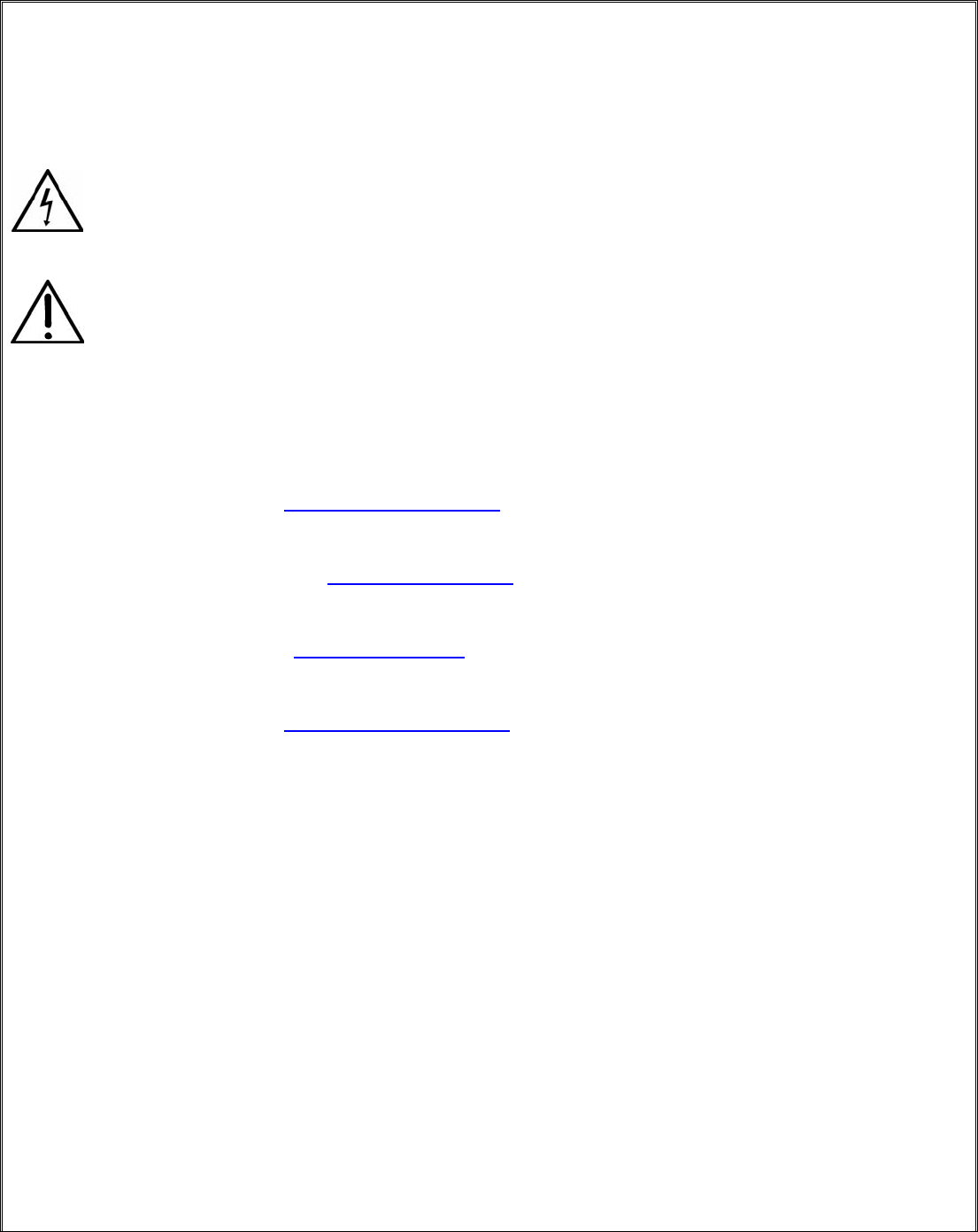
PRO-SVR_LEGACY Page 3 of 13
Introduction
Please read this manual carefully before commencing servicing!
Only qualified and authorized personnel should attempt to service this product.
The lightning flash with arrowhead symbol, within an equilateral triangle, is intended
to alert the user to the presence of uninsulated dangerous voltage within the
product’s enclosure that may be of sufficient magnitude to constitute a risk of electric
shock to persons.
The exclamation point within an equilateral triangle is intended to alert the user to
the presence of important operating and maintenance (servicing) instructions.
Classé has a global product support network. For product assistance or to order replacement parts please
contact your nearest service center always quoting the unit serial number.
North America
Phone: (978) 664-2870 E-mail: classe@bwgroupusa.com
Europe
Phone: 44 (0) 1903 221 700 E-mail: classe@bwgroup.com
Asia
Phone: (852) 2790 8903 E-mail: classe@bwgroup.hk
Rest of the World
Phone: (514) 636-6384 E-mail: cservice@classeaudio.com
Important Notes on Servicing
1. ALWAYS observe ESD precautions when handling electronic modules or PCBAs.
2. NEVER exchange boards with a different revision number, unless authorized by Classé.
3. ALWAYS use Classé original replacement parts. The use of generic parts may void the warranty of
the unit.
Ordering Replacement Parts
There may be a delay in processing incomplete requests. Please be sure to include all required information.
Remember to quote the serial number of the unit on all replacement part orders and the Classé order number
when returning defective parts for credit.
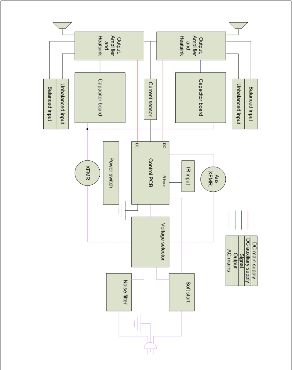
PRO-SVR_LEGACY Page 4 of 13
Block diagrams

PRO-SVR_LEGACY Page 5 of 13
Start Up Procedure
When receiving a unit, an assiduous visual inspection must be performed. Do not connect the unit without
analysing the symptoms reported by the customer and the results of the inspection.
Using the troubleshooting guide, find the problem and proceed to the repair. Once this step is done, follow
these steps, known as the start-up procedure, to ensure that everything in the unit is in working condition.
1. Proceed with a post repair visual inspection. Take the time to check if every wire is reconnected
properly, every screw is bolted on, no soldering and/or metal residues lying in the unit, every fuse has
been replaced, etc.
2. Connect the unit to a variable transformer, setted to 0Vac.
3. Turn the bias trimpot (RV1) counter clockwise until a click is heard.
4. Connect the bypass wire to the variable transformer. This bypass is a power cord, modified on the
female side in order to bypass the soft start sequence. It is connected to the line tab on voltage
selector PCB.
5. Slowly raise the voltage to 10Vac, and check positive and negative rails and pre-driver supply. Check
fuses.
6. If one or more supply are not within specifications, return to the troubleshooting guide.
7. Slowly raise voltage until you hear relays click, this point is around 55Vac. Recheck every supply.
8. If one or more supply are not within specifications, return to the troubleshooting guide.
9. Raise voltage to 120Vac. Recheck every supply
10. If every supply is within specifications, unplug the unit and bypass from the variable transformer.
Reconnect only the unit.
11. Report to calibration and adjusments to adjust bias and DC offset. Note that bias can be adjusted to
14mV, and the following tests can be performed before the unit is send to the burn-in bench for a 24
hours warm-up.
12. Connect the unit to a load, and to a source using balanced inputs and single ended inputs,
independently.
13. Perform a test with a 200Hz, a 2kHz and a 20kHz tone, both sinus wave and square wave. Check the
output with a oscilloscope, on 4 ohms and 8 ohms loads. Take special cares about oscillation and phase
correlation between channels.
14. Connect the unit to a small speaker, and short the input. Check for any noise. Perform this step with
single ended inputs and balanced inputs, independently.
15. Put the unit on a burn-in bench, and let it sit for 24 hours, then readjust bias. Let the unit on the burn-
in bench for another 72 hours.
16. Redo steps 11 to 14 before shipping to the customer.

PRO-SVR_LEGACY Page 6 of 13
Protection Modes and Indicators
The front LED shows the status of the amplifier. When starting up normally, the CAM350 will show a
FLASHING RED LED for about 15 seconds and if all is normal, the LED will go SOLID RED. If there is a fault,
the LED will go to a FLASHING GREEN LED. The CAM350 is equipped with four Mosfet protection fuses. In the
event that one or more of these fuses would blow, the technician will first need to identify and cure the cause
of failure (please report to troubleshooting guide). When the cause has been identified, disconnect the unit
from the system including the AC power. Remove the top cover and look for damaged or burned components.
If no other components than the fuses appear to be damaged, the technician can then replace the broken
fuses with the same value and rating (please report to fuses section). The Mosfet fuses are located on the
control board. When replacing fuses, please make sure that the fuse holder are holding the fuses very tightly.
A loose fuse holder can translate into distortion on top of the signal.

PRO-SVR_LEGACY Page 7 of 13
Troubleshooting Guide
Symptom Possible cause
Unit won’t turn on Check connections;
Check fuses;
Check soft-start circuit;
Check relays;
Check power supply circuits (positive rail, negative rail, Mosfet
supply).
Smoked and/or burned
components
Check for short between components and ground;
Check output transistors;
Check output relays;
Check power supply circuits (positive rail, negative rail, Mosfet
supply).
Blown fuses Check for short between fuse and ground;
Check power supply circuits (positive rail, negative rail, Mosfet
supply).
No output Check connexions;
Check output relays;
Check power supply circuits (positive rail, negative rail, Mosfet
supply);
Check output transistors.
Unit turn into protection Check for smoked and/or burned components;
Check power supply circuits (positive rail, negative rail, Mosfet
supply);
Check source and load;
Check protection circuit;
Check sensor wires between sensor PCB and control PCB;
Check outputs transistors and Mosfet drivers.
Excessive buzz and/or hum Check electrical lines;
Check for a ground loop in the system.
Oscillation Check source;
Check capacitors on main board;
Check 4.7Ω resistor.
Intermittent signal Check connections;
Replace shield wires.
PRO-SVR_LEGACY Page 8 of 13
Output Transistors Testing and Replacement
PLEASE NOTE THAT THESE TESTS ARE ONLY EFFECTIVE ON BIPOLAR TRANSISTORS.
DO NOT PERFORM THESE TESTS ON MOSFET DEVICES, AS THEY ARE LIKELY TO
BECOME SHORT DURING THE TEST.
You should check all pin combinaisons, as there is a chance that only one side of the transistor is short. When
replacing outputs transistors, the technician should first disconnect both outputs and main board to check if
the blown outputs were caused by a faulty component on the amplifier’s base. Blown output transistors should
be replaced by kits, not individually. These kits contains matched transistors for both rails of one channel.
When replacing blown output transistors, you must also replace positive and negative Mosfet drivers and bias
transistor. Carefully inspect 4.7Ω resistor and 10Ω soft start resistor, and replace if necessary. Replace any
burnt component or board.
Pins : 1 Base
2 Collector
3 Emitter
You should have these results, if the transistor is good.
2SC3264 (NPN)
Positive lead Negative lead Result
B C Conductive
B E Conductive
C B Infinite
C E Infinite
E B Infinite
E C Infinite
2SA1295 (PNP)
Positive lead Negative lead Result
B C Infinite
B E Infinite
C B Conductive
C E Infinite
E B Conductive
E C Infinite

PRO-SVR_LEGACY Page 9 of 13
Calibrations and Adjustments
Bias adjustment:
Note: Bias adjustment should be made without any load connected to the amplifier’s output, and no signal
connected to the amplifier’s input.
1. On positive heatsink, connect a multimeter to R111 leads and set the multimeter to mV scale.
2. Turn trimpot R104 counterclockwise until it reaches 0Ω. A click should be heard.
3. Turn on amplifier, and let it warm up for 15 minutes on idle.
4. Adjust trimpot R104 to get a 10mV reading.
5. Repeat procedure with negative heatsink.
6. Let the amplifier warm up for a 24 hours period with signal and load.
7. Remove signal and load, and reconnect the multimeter, setted to mV scale, to R112 leads.
8. Readjust R104 to get a 12mV reading.
9. Repeat procedure with negative heatsink.
DC offset:
Note: DC offset adjustment should be made without any load connected to the amplifier’s output, and no
signal connected to the amplifier’s input.
On these units, DC offset can’t be adjusted. Measure DC offset using a voltmeter connected to the output
posts, scale setted to mV. DC offset should be less than 10mV.

PRO-SVR_LEGACY Page 10 of 13
Parts List
This is not a detailed part list. It is a list of major chassis parts and PCBs. If you need to order a specific part,
please contact Classe Audio with the part location, PCB number, and model and serial number of the unit.
If you need a complete PCB, please replace the (x) in the Classe part number with the revision number printed
on the board.
Parts Description Classe part number
B1DAX Complete PCB, power switch B1DAXR(x)
B1D1X Complete PCB, heatsink B1D1XR(x)
B02AX Complete PCB, amplifier B02AXR(x)
B1B3X Complete PCB, control B1B3XR(x)
B1B1X Complete PCB, capacitors B1B1XR(x)
B016X Complete PCB, AC B016XR(x)
B258X Complete PCB, input B258XR(x)
B019X Complete PCB, sensor B019XR(x)
B01GX Complete PCB, filter B01GXR(x)
B1B2X Complete PCB, supply B1B2XR(x)

PRO-SVR_LEGACY Page 11 of 13
Updates
1. On board B1D1X (both PCBs), replace R104 with Classe part number 3299X-1-202.
2. On board B1D1X (both PCBs), replace D101 and D103 with Classe part number 1N5333B.
3. On board B1B3X, replace P011XR02 to 040AR3, and drop rail voltage sensor from 500mV to 250mV.
4. Add a jumper from GND post on B1B1X PCB to relay GND on B1B3X PCB.
PRO-SVR_LEGACY Page 12 of 13
Fuses
EXTRA PRECAUTIONS SHOULD BE TAKEN WHEN REPAIRING, MODIFYING, O
TROUBLESHOOTING IN THE POWER SUPPLY AREA. UNIT MUST BE DISCONNEC
FROM MAIN SOURCE AND CAPACITORS MUST BE DISCHARGED USING A 100W
INCANDESCENT BULB.
WHEN REPLACING FUSES, PLEASE MAKE SURE THAT THE FUSE HOLDERS ARE
HOLDING THE FUSES VERY TIGHTLY. A LOOSE FUSE HOLDER CAN TRANSLATE INTO
DISTORTION ON TOP OF THE SIGNAL.
Main fuses:
For 100 – 120v units: 10A slo-blo, Classe part number MDA-10A
For 220 – 240v units: 4A slo-blo, Classe part number MD
The main fuse is located at the back of the unit, on the rear panel.
Control board fuse: 0.50A, Classe part number 225.500
The control board fuse is located on top of the supply board (B1B2X)
Mosfet fuses: 0.75A, Classe part number 225.750
The Mosfet fuses are located on top of the supply board (B1B2X)
Voltage Change
EXTRA PRECAUTIONS SHOULD BE TAKEN WHEN REPAIRING, MODIFYING, O
TROUBLESHOOTING IN THE POWER SUPPLY AREA. UNIT MUST BE DISCONNEC
FROM MAIN SOURCE AND CAPACITORS MUST BE DISCHARGED USING A 100W
INCANDESCENT BULB.
1. Set the primary wires of the main transformer as described below.
2. Replace the varistor, according to new line voltage, following Classe’s recommendations. If varistor is
not available, remove old varistor and leave it empty.
3. Set the jumpers accordingly on the auxiliary transformer located at the back of the unit on the top
main board on the left-hand side of the auxiliary transformer (see tables below)
Primary wires, main transformer
Mains X1 X2 X3 X4 X5 X6 X7 X8 Varist
or
100VAC Grey Yellow Blue Black Orange White — — 130
120VAC Blue Black Grey Yellow Orange White — — 130
220VAC — Yellow Grey Black — White Blue Orange 250
240VAC — Black Grey Yellow — White Blue Orange 250
Jumpers, auxiliary transformer
Mains Position 1 Position 2 Position 3 Position 4 Position 5
100/120VAC In Out Out Out In
220/240VAC Out Out In Out Out

PRO-SVR_LEGACY Page 13 of 13
IR Interface Information
Press and hold: AMP + LINE 1 = Turns on Amplifier # 1
AMP + LINE 2 = Turns on Amplifier # 2
AMP + LINE 3 = Turns on Amplifier # 3
AMP + BAL 1 = Turns on Amplifier # 4
AMP + BAL 2 = Turns on Amplifier # 5
AMP + BAL 3 = Turns on Amplifier # 6
J3 J2 J1 J0 ADDRESS RC Button Auto ON Note
X X X X 0 Amp1 No QC setting
X X X Out 1 Amp2 No
X X Out X 2 Amp3 No
X X Out Out 3 Amp4 No
X Out X X 4 Amp5 No
X Out X Out 5 Amp6 No
X Out Out X 0 Amp1 No
X Out Ot Out 0 Amp1 Yes On with AC
Out X X X 0 DC No
Out X X Out 1 DC No
Out X Out X 2 DC No
Out X Out Out 3 DC No
Out Out X X 4 DC No
Out Out X Out 5 DC No
Out Out Out X 0 DC No
Out Out Out Out 0 DC Yes On with AC
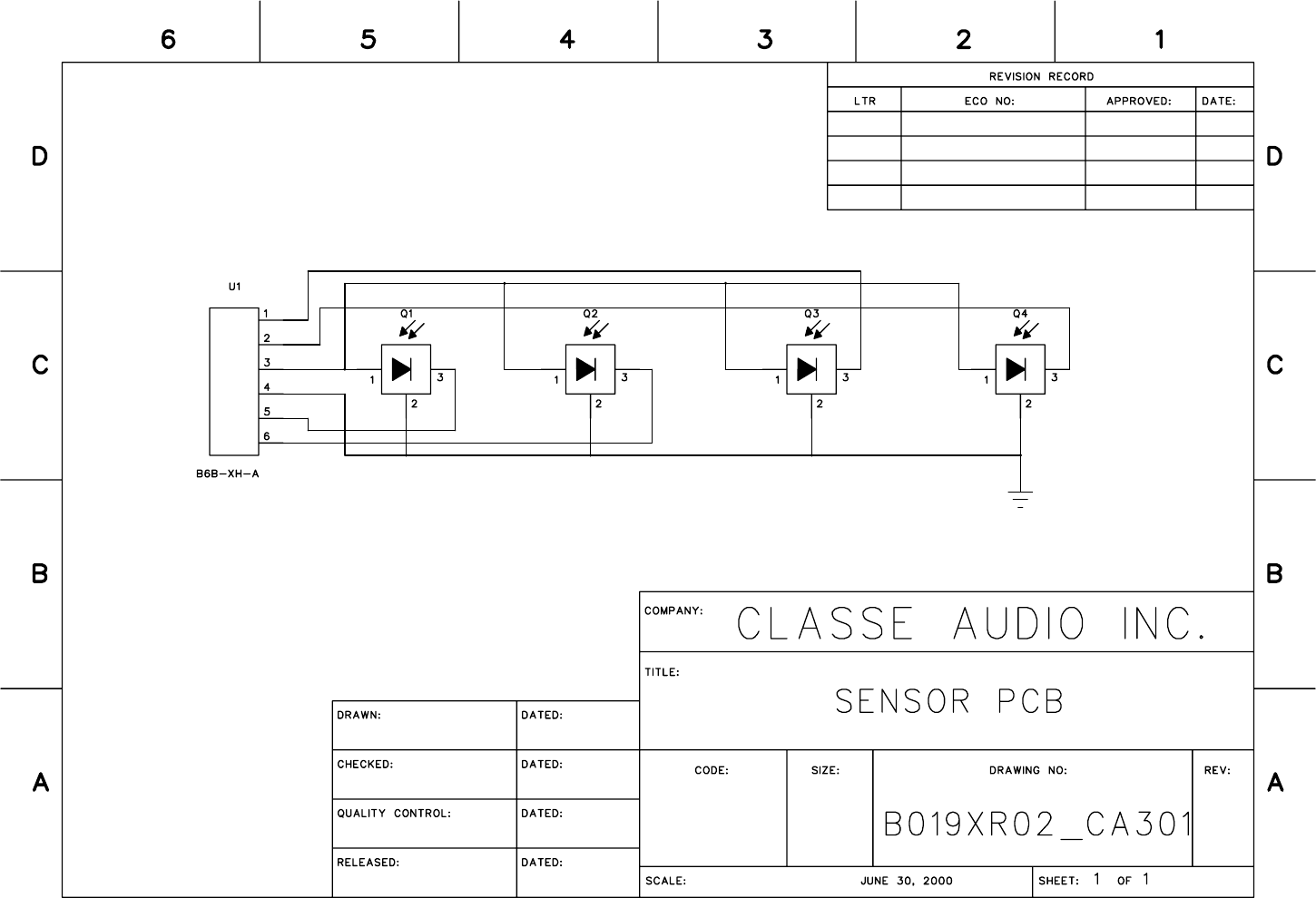
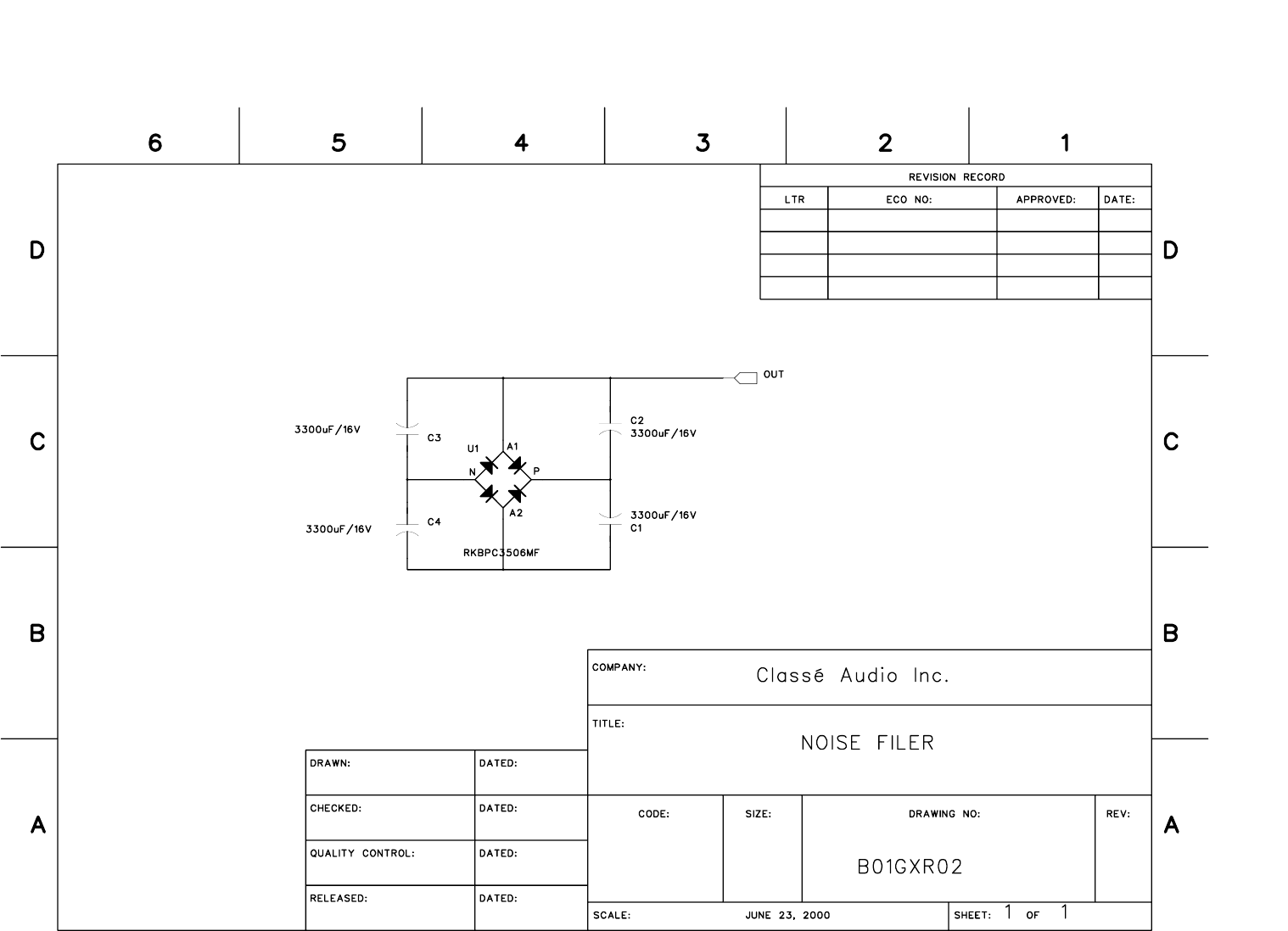
B01GXR02.sch-1 — Tue Jul 17 11:41:29 2007
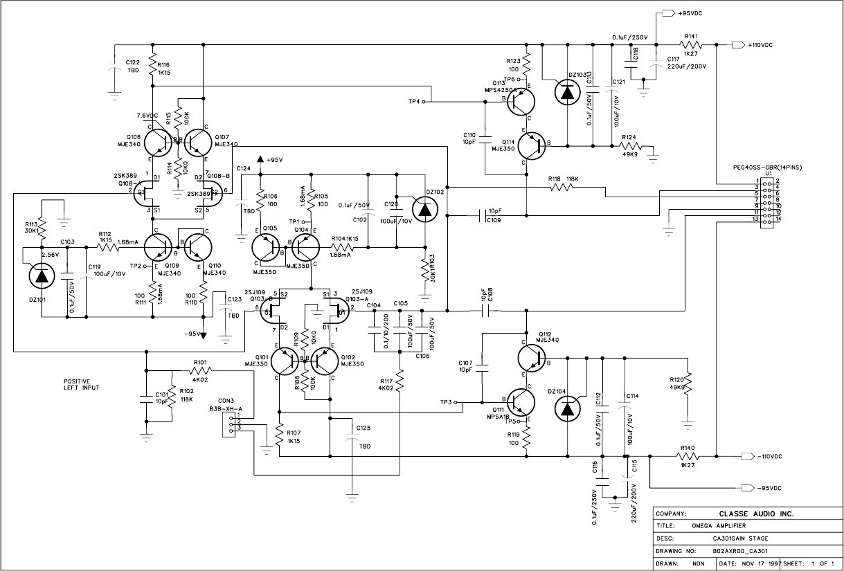
B02AXR01.sch-1 — Thu Jul 26 16:15:20 2007
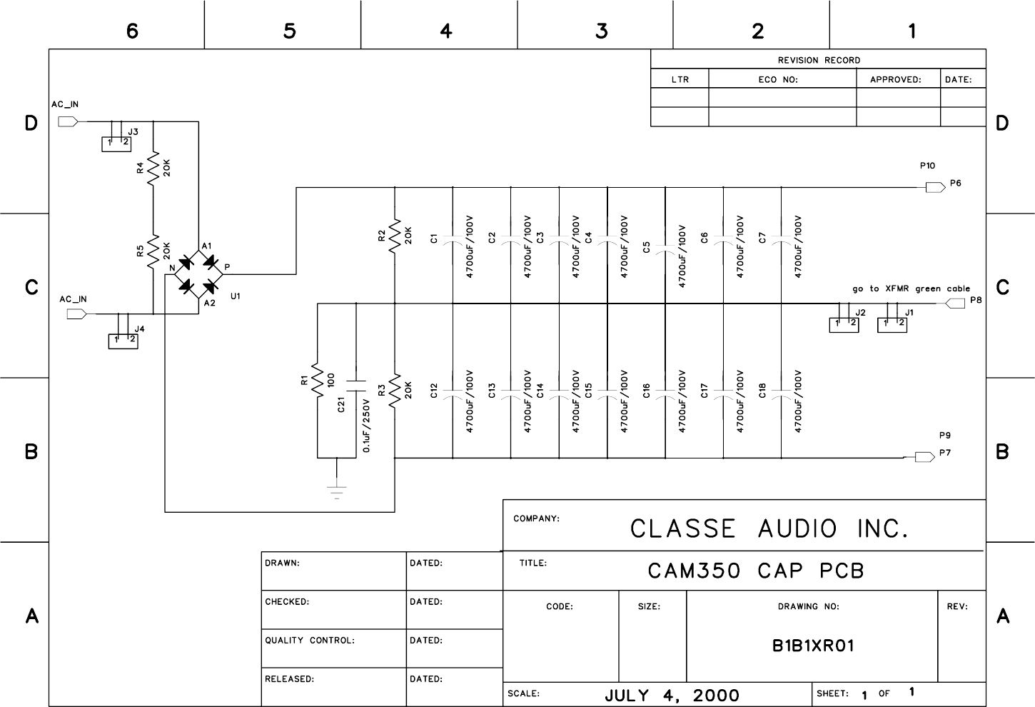
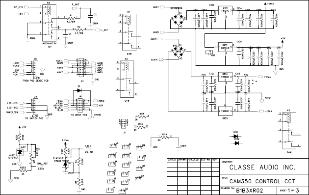
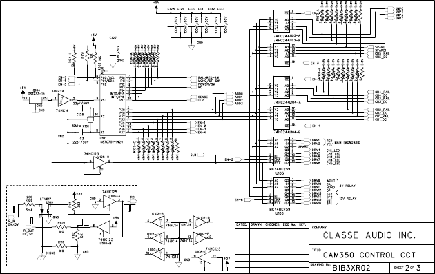
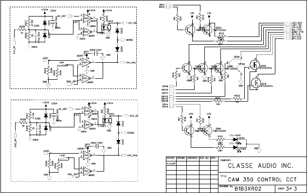
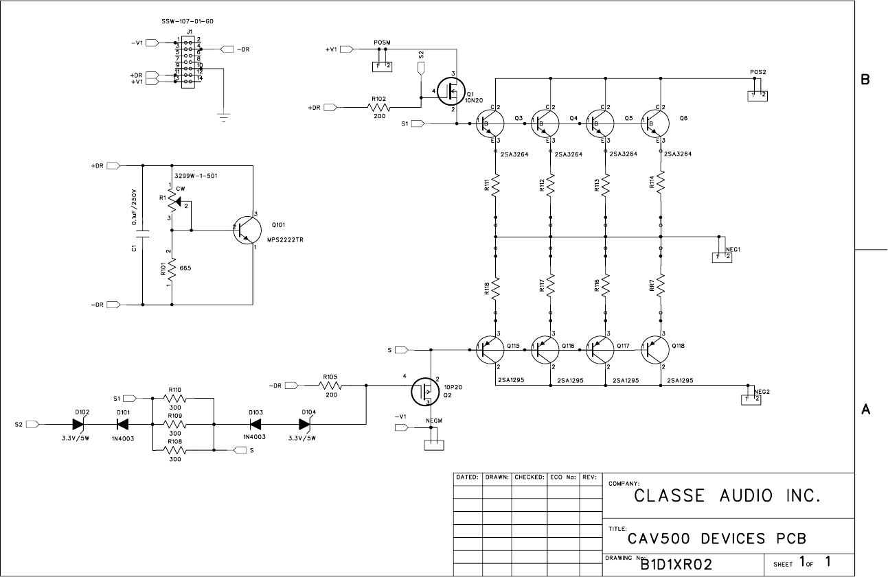
B1D1XR02.sch-1 — Thu Jul 26 16:16:26 2007
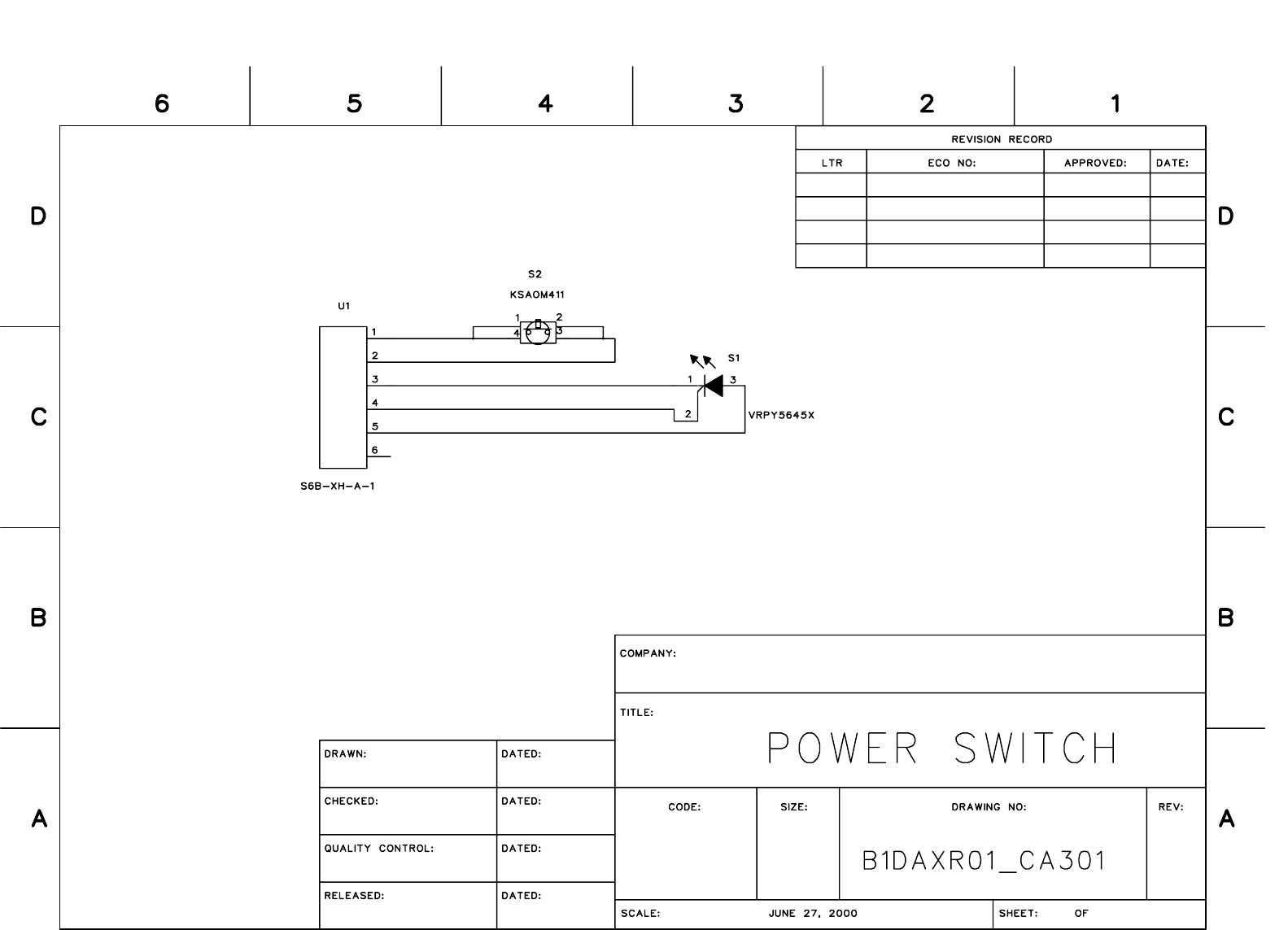
B1DAXR01.sch-1 — Thu Jul 26 16:16:52 2007
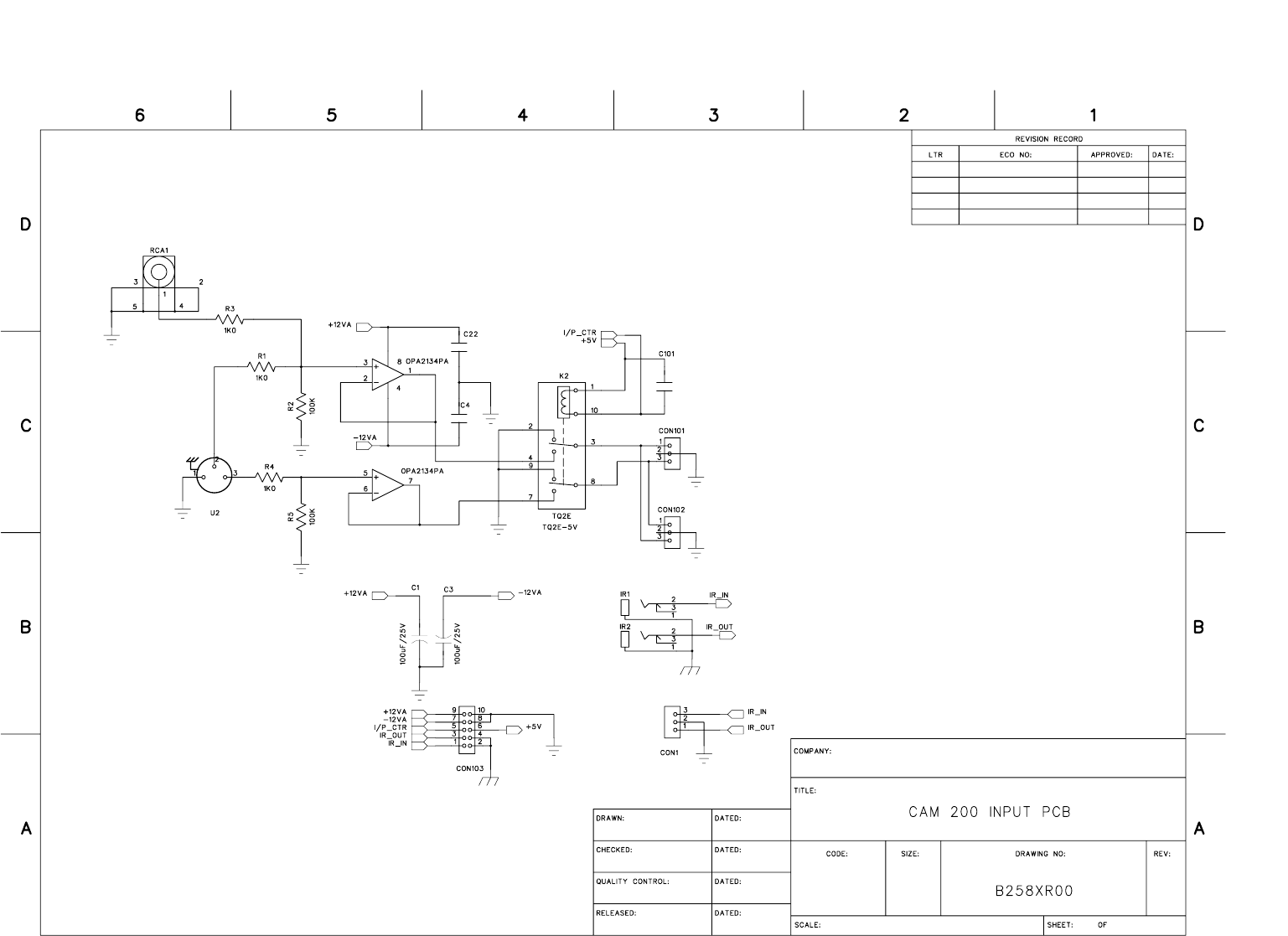
B258XR00.sch-1 — Thu Jul 26 16:15:00 2007