- Manuals
- Brands
- Canon Manuals
- All in One Printer
- iR2420 series
Manuals and User Guides for Canon iR2420 series. We have 1 Canon iR2420 series manual available for free PDF download: Service Manual
![]()
Service Manual
iR2422/2420/2320/2318 Series
Apr 20 2011
Application
This manual has been issued by Canon Inc. for qualified persons to learn technical theory, installation, maintenance, and repair of products. This manual covers all localities where the products are sold. For this reason, there may be information in this manual that does not apply to your locality.
Corrections
This manual may contain technical inaccuracies or typographical errors due to improvements or changes in products. When changes occur in applicable products or in the contents of this manual, Canon will release technical information as the need arises. In the event of major changes in the contents of this manual over a long or short period, Canon will issue a new edition of this manual.
The following paragraph does not apply to any countries where such provisions are inconsistent with local law.
Trademarks
The product names and company names used in this manual are the registered trademarks of the individual companies.
Copyright
This manual is copyrighted with all rights reserved. Under the copyright laws, this manual may not be copied, reproduced or translated into another language, in whole or in part, without the written consent of Canon Inc.
COPYRIGHT © 2001 CANON INC.
Printed in Japan
Caution
Use of this manual should be strictly supervised to avoid disclosure of confidential information.

Introduction
Symbols Used
This documentation uses the following symbols to indicate special information:
Symbol Description
Indicates an item of a non-specific nature, possibly classified as Note, Caution, or Warning.
Indicates an item requiring care to avoid electric shocks.
Indicates an item requiring care to avoid combustion (fire).
Indicates an item prohibiting disassembly to avoid electric shocks or problems.
Indicates an item requiring disconnection of the power plug from the electric outlet.
Indicates an item intended to provide notes assisting the understanding of the topic in question.
Memo
Indicates an item of reference assisting the understanding of the topic in question.
REF.
Provides a description of a service mode.
Provides a description of the nature of an error indication.

Introduction
The following rules apply throughout this Service Manual:
1.Each chapter contains sections explaining the purpose of specific functions and the relationship between electrical and mechanical systems with reference to the timing of operation.
In the diagrams,  represents the path of mechanical drive; where a signal name accompanies the symbol , the arrow
  indicates the
direction of the electric signal.
The expression «turn on the power» means flipping on the power switch, closing the front door, and closing the delivery unit door, which results in supplying the machine with power.
2.In the digital circuits, ‘1’is used to indicate that the voltage level of a given signal is «High», while ‘0’ is used to indicate «Low».(The voltage value, however, differs from circuit to circuit.) In addition, the asterisk (*) as in «DRMD*» indicates that the DRMD signal goes on when ‘0’.
In practically all cases, the internal mechanisms of a microprocessor cannot be checked in the field. Therefore, the operations of the microprocessors used in the machines are not discussed: they are explained in terms of from sensors to the input of the DC controller PCB and from the output of the DC controller PCB to the loads.
The descriptions in this Service Manual are subject to change without notice for product improvement or other purposes, and major changes will be communicated in the form of Service Information bulletins.
All service persons are expected to have a good understanding of the contents of this Service Manual and all relevant Service Information bulletins and be able to identify and isolate faults in the machine.»

Contents
Contents
|
Chapter 1 Introduction |
|
|
1.1 System Construction …………………………………………………………………………………………………………………. |
1- 1 |
1.1.1Pickup/ Delivery /Original Handling Accessories System Configuration (1-cassette/Platen cover (option) model) 1- 1
1.1.2Pickup/ Delivery /Original Handling Accessories System Configuration (1-cassette/Platen cover (standard) model)1-
2
1.1.3 Pickup/ Delivery /Original Handling Accessories System Configuration (2-cassette/Duplex unit (option) model) .. 1- 3 1.1.4 Pickup/ Delivery /Original Handling Accessories System Configuration (2-cassette/Duplex unit (standard) model) .1-
|
4 |
|
|
1.1.5 Reader Heater/ Cassette Heater System Configuration……………………………………………………………………………… |
1- 5 |
|
1.1.6 Printing/Transmitting Accessories System Configuration……………………………………………………………………………. |
1- 6 |
|
1.2 Product Specifications ……………………………………………………………………………………………………………….. |
1- 6 |
|
1.2.1 Names of Parts…………………………………………………………………………………………………………………………………….. |
1- 6 |
|
1.2.1.1 External View (1-cassette model) …………………………………………………………………………………………………………………………. |
1- 6 |
|
1.2.1.2 External View (2-cassette model) ………………………………………………………………………………………………………………………….. |
1- 6 |
|
1.2.1.3 Cross-Section …………………………………………………………………………………………………………………………………………………….. |
1- 7 |
|
1.2.2 Using the Machine………………………………………………………………………………………………………………………………… |
1- 7 |
|
1.2.2.1 Turning On the Power Switch (1-cassette model) …………………………………………………………………………………………………… |
1- 7 |
|
1.2.2.2 Turning On the Power Switch (2-cassette model) ……………………………………………………………………………………………………. |
1- 8 |
|
1.2.2.3 When Turning Off the Main Power Switch (1-cassette model) ………………………………………………………………………………….. |
1- 9 |
|
1.2.2.4 When Turning Off the Main Power Switch (2-cassette model) …………………………………………………………………………………. |
1- 11 |
|
1.2.2.5 Control Panel ……………………………………………………………………………………………………………………………………………………. |
1- 12 |
|
1.2.3 User Mode Items ………………………………………………………………………………………………………………………………… |
1- 13 |
|
1.2.3.1 Audible Tones …………………………………………………………………………………………………………………………………………………… |
1- 13 |
|
1.2.3.2 Common Settings ……………………………………………………………………………………………………………………………………………… |
1- 13 |
|
1.2.3.3 Copy Settings……………………………………………………………………………………………………………………………………………………. |
1- 14 |
|
1.2.3.4 Printer Settings …………………………………………………………………………………………………………………………………………………. |
1- 14 |
|
1.2.3.5 Timer Settings…………………………………………………………………………………………………………………………………………………… |
1- 15 |
|
1.2.3.6 Adjustment/Cleaning………………………………………………………………………………………………………………………………………….. |
1- 15 |
|
1.2.3.7 Report Settings …………………………………………………………………………………………………………………………………………………. |
1- 15 |
|
1.2.3.8 System Settings ………………………………………………………………………………………………………………………………………………… |
1- 15 |
|
1.2.3.9 Network Settings……………………………………………………………………………………………………………………………………………….. |
1- 16 |
|
1.2.4 Maintenance by the User……………………………………………………………………………………………………………………… |
1- 17 |
|
1.2.4.1 User Maintenance Items …………………………………………………………………………………………………………………………………….. |
1- 17 |
|
1.2.4.2 Cleaning…………………………………………………………………………………………………………………………………………………………… |
1- 17 |
|
1.2.5 Safety ……………………………………………………………………………………………………………………………………………….. |
1- 19 |
|
1.2.5.1 Safety of the Laser Light …………………………………………………………………………………………………………………………………….. |
1- 19 |
|
1.2.5.2 CDRH Regulations…………………………………………………………………………………………………………………………………………….. |
1- 19 |
|
1.2.5.3 Handling the Laser Unit ……………………………………………………………………………………………………………………………………… |
1- 19 |
|
1.2.5.4 Safety of Toner …………………………………………………………………………………………………………………………………………………. |
1- 20 |
|
1.2.5.5 Point to Note about Fire ……………………………………………………………………………………………………………………………………… |
1- 20 |
|
1.2.6 Product Specifications …………………………………………………………………………………………………………………………. |
1- 20 |
|
1.2.6.1 Product Specifications ……………………………………………………………………………………………………………………………………….. |
1- 20 |
|
1.2.7 Function List ………………………………………………………………………………………………………………………………………. |
1- 21 |
|
1.2.7.1 Printing Speed (iR2422series) …………………………………………………………………………………………………………………………….. |
1- 21 |
|
1.2.7.2 Printing Speed (iR2420/iR2320series)………………………………………………………………………………………………………………….. |
1- 23 |
|
1.2.7.3 Printing Speed (iR2318series) …………………………………………………………………………………………………………………………….. |
1- 24 |
|
Chapter 2 Installation |
|
|
2.1 Making Pre-Checks …………………………………………………………………………………………………………………… |
2- 1 |
|
2.1.1 Selecting the Site of Installation ……………………………………………………………………………………………………………… |
2- 1 |
|
2.1.2 Before Starting the Work (120VCLA) ………………………………………………………………………………………………………. |
2- 1 |
|
2.1.3 Before Starting the Work (230VCLA) ………………………………………………………………………………………………………. |
2- 3 |

Contents
|
2.1.4 Before Starting the Work (230VEUR) ………………………………………………………………………………………………………. |
2- 5 |
|
2.1.5 Before Starting the Work (230VCSPL) …………………………………………………………………………………………………….. |
2- 7 |
|
2.1.6 Before Starting the Work (230V CCN) ……………………………………………………………………………………………………… |
2- 9 |
|
2.2 Unpacking and Installation ……………………………………………………………………………………………………….. |
2- 11 |
|
2.2.1 Unpacking and Removing the Packaging Materials …………………………………………………………………………………. |
2- 11 |
|
2.2.2 Installing the Drum Unit………………………………………………………………………………………………………………………… |
2- 11 |
|
2.2.3 Installing the Toner Bottle …………………………………………………………………………………………………………………….. |
2- 12 |
|
2.2.4 Setting the Cassettes…………………………………………………………………………………………………………………………… |
2- 14 |
|
2.2.5 Checking the Image Quality………………………………………………………………………………………………………………….. |
2- 15 |
|
2.3 Flow of Accessory Installation …………………………………………………………………………………………………… |
2- 16 |
|
2.3.1 Flow of Accessary Installation……………………………………………………………………………………………………………….. |
2- 16 |
|
2.4 Installing the Heater PCB …………………………………………………………………………………………………………. |
2- 17 |
|
2.4.1 Preparing the parts ……………………………………………………………………………………………………………………………… |
2- 17 |
|
2.4.2 Preparing the Host Machine …………………………………………………………………………………………………………………. |
2- 17 |
|
2.4.3 Installing the Heater PCB……………………………………………………………………………………………………………………… |
2- 18 |
|
2.5 Installing the Reader Heater……………………………………………………………………………………………………… |
2- 21 |
|
2.5.1 Preparing the parts ……………………………………………………………………………………………………………………………… |
2- 21 |
|
2.5.2 Installing the Reader Heater Harness…………………………………………………………………………………………………….. |
2- 22 |
|
2.5.3 Removing Reader Components…………………………………………………………………………………………………………….. |
2- 25 |
|
2.5.4 Removing Parts at the Left of the Reader……………………………………………………………………………………………….. |
2- 25 |
|
2.5.5 Installing the Reader Heater …………………………………………………………………………………………………………………. |
2- 26 |
|
2.6 Installing the Cassette Heater …………………………………………………………………………………………………… |
2- 28 |
|
2.6.1 Preparing the parts ……………………………………………………………………………………………………………………………… |
2- 28 |
|
2.6.2 Installing the Cassette Heater……………………………………………………………………………………………………………….. |
2- 28 |
|
Chapter 3 Main Controller |
|
|
3.1 Construction …………………………………………………………………………………………………………………………….. |
3- 1 |
|
3.1.1 Constraction and Mechanisms………………………………………………………………………………………………………………… |
3- 1 |
|
3.2 Construction of the Electrical Circuitry………………………………………………………………………………………….. |
3- 1 |
|
3.2.1 Image processor PCB……………………………………………………………………………………………………………………………. |
3- 1 |
|
3.3 Image Processing……………………………………………………………………………………………………………………… |
3- 2 |
|
3.3.1 Overview of Image flow…………………………………………………………………………………………………………………………. |
3- 2 |
|
3.3.2 Configration of Image processing Module ……………………………………………………………………………………………….. |
3- 2 |
|
3.3.3 Reader entry Image processing………………………………………………………………………………………………………………. |
3- 3 |
|
3.3.4 Compression/extension/edit processing block…………………………………………………………………………………………… |
3- 3 |
|
3.3.5 Printer output Image processing ……………………………………………………………………………………………………………. |
3- 4 |
|
3.4 Flow of Image Data …………………………………………………………………………………………………………………… |
3- 4 |
|
3.4.1 Image data flow of copy function ……………………………………………………………………………………………………………. |
3- 4 |
|
3.4.2 Image data flow of BDL function ……………………………………………………………………………………………………………… |
3- 5 |
|
3.5 Parts Replacement Procedure ……………………………………………………………………………………………………. |
3- 6 |
|
3.5.1 Main Controller PCB ……………………………………………………………………………………………………………………………… |
3- 6 |
|
3.5.1.1 Preparation for Removing the image processor PCB ……………………………………………………………………………………………….. |
3- 6 |
|
3.5.1.2 Removing the Image Processor PCB …………………………………………………………………………………………………………………….. |
3- 6 |
|
3.5.1.3 Procedure after Replacing the Image Processor PCB………………………………………………………………………………………………. |
3- 6 |
|
Chapter 4 Original Exposure System |
|
|
4.1 Construction …………………………………………………………………………………………………………………………….. |
4- 1 |
4.1.1Specifications, Control Methods, and Functions (When the original size detection sensor is equipped for BOOK mode) 4- 1
4.1.2Specifications, Control Methods, and Functions (When the original size detection sensor is not equipped for BOOK
|
mode)……………………………………………………………………………………………………………………………………………………… |
4- 1 |
|
4.1.3 Major Components (When the original size detection sensor is equipped for BOOK mode) ……………………………. |
4- 2 |
|
4.1.4 Major Components (When the original size detection sensor is not equipped for BOOK mode) ………………………. |
4- 3 |
|
4.1.5 Control System Configuration (When the original size detection sensor is equipped for BOOK mode)……………… |
4- 3 |
|
Contents |
|
|
4.1.6 Control System Configuration (When the original size detection sensor is not equipped for BOOK mode) |
………..4- 4 |
|
4.1.7 Reader Controller PCB (When the original size detection sensor is equipped for BOOK mode)………………………. |
4- 5 |
|
4.1.8 Reader Controller PCB (When the original size detection sensor is not equipped for BOOK mode)…………………. |
4- 5 |
|
4.2 Basic Sequence………………………………………………………………………………………………………………………… |
4- 6 |
|
4.2.1 Basic Sequence at Power-on …………………………………………………………………………………………………………………. |
4- 6 |
|
4.2.2 Basic Sequence after Depression of Start Key (Book mode, One Sheet of original) ………………………………………. |
4- 7 |
|
4.3 Various Control…………………………………………………………………………………………………………………………. |
4- 8 |
|
4.3.1 Controlling the Scanner Drive System……………………………………………………………………………………………………… |
4- 8 |
|
4.3.1.1 Outline……………………………………………………………………………………………………………………………………………………………….. |
4- 8 |
|
4.3.1.2 Reader Motor Control ………………………………………………………………………………………………………………………………………….. |
4- 8 |
|
4.3.2 Contact Image Sensor (CIS) ………………………………………………………………………………………………………………….. |
4- 9 |
|
4.3.2.1 Outline……………………………………………………………………………………………………………………………………………………………….. |
4- 9 |
|
4.3.2.2 Analog Control Performed by the CIS…………………………………………………………………………………………………………………… |
4- 10 |
|
4.3.3 Enlargement/Reduction ……………………………………………………………………………………………………………………….. |
4- 11 |
|
4.3.3.1 Magnification Change in Vertical Scan Direction ……………………………………………………………………………………………………. |
4- 11 |
|
4.3.3.2 Magnification Change in Horizontal Scan Direction………………………………………………………………………………………………… |
4- 11 |
|
4.3.4 Detecting the Size of Originals ……………………………………………………………………………………………………………… |
4- 11 |
|
4.3.4.1 Outline……………………………………………………………………………………………………………………………………………………………… |
4- 11 |
|
4.3.4.2 Outline of Original Size Detection ………………………………………………………………………………………………………………………… |
4- 12 |
|
4.3.5 Dirt Sensor Control ……………………………………………………………………………………………………………………………… |
4- 13 |
|
4.3.5.1 Outline……………………………………………………………………………………………………………………………………………………………… |
4- 13 |
|
4.3.6 Image Processing……………………………………………………………………………………………………………………………….. |
4- 15 |
|
4.3.6.1 Outline……………………………………………………………………………………………………………………………………………………………… |
4- 15 |
|
4.3.6.2 CMOS Sensor Drive ………………………………………………………………………………………………………………………………………….. |
4- 16 |
|
4.3.6.3 CMOS Sensor Output Gain Correction and Offset Correction………………………………………………………………………………….. |
4- 16 |
|
4.3.6.4 CMOS Sensor Output A/D Conversion…………………………………………………………………………………………………………………. |
4- 16 |
|
4.3.6.5 Shading Correction (Outline) ………………………………………………………………………………………………………………………………. |
4- 16 |
|
4.3.6.6 Shading Adjustment…………………………………………………………………………………………………………………………………………… |
4- 16 |
|
4.3.6.7 Shading Correction ……………………………………………………………………………………………………………………………………………. |
4- 17 |
|
4.4 Parts Replacement Procedure ………………………………………………………………………………………………….. |
4- 18 |
|
4.4.1 Copyboard glass…………………………………………………………………………………………………………………………………. |
4- 18 |
|
4.4.1.1 Removing the Copyboard glass…………………………………………………………………………………………………………………………… |
4- 18 |
|
4.4.1.2 Removing the ADF Reading Glass (only for ADF equipment)………………………………………………………………………………….. |
4- 18 |
|
4.4.2 Reader Controller PCB………………………………………………………………………………………………………………………… |
4- 18 |
|
4.4.2.1 Removing the Reader Controller PCB (When the original size detection sensor is not equipped for BOOK mode)…………. |
4- 18 |
|
4.4.2.2 Removing the Reader Controller PCB (When the original size detection sensor is equipped for BOOK mode)………………. |
4- 20 |
|
4.4.3 Scanner Motor ……………………………………………………………………………………………………………………………………. |
4- 21 |
|
4.4.3.1 Removing the Scanner Motor ……………………………………………………………………………………………………………………………… |
4- 21 |
|
4.4.4 Contact sensor …………………………………………………………………………………………………………………………………… |
4- 22 |
|
4.4.4.1 Removing the Contact Image Sensor (CIS)…………………………………………………………………………………………………………… |
4- 22 |
|
4.4.4.2 Procedure after Replacing the CIS ………………………………………………………………………………………………………………………. |
4- 22 |
|
4.4.5 Copyboard Cover Open/Close Sensor …………………………………………………………………………………………………… |
4- 22 |
|
4.4.5.1 Removing the Copyboard Cover Open/Close Sensor (Front/Rear)…………………………………………………………………………… |
4- 22 |
|
4.4.6 Contact Sensor HP Sensor ………………………………………………………………………………………………………………….. |
4- 23 |
|
4.4.6.1 Removing the Contact Sensor HP Sensor (When the ADF is not installed)……………………………………………………………….. |
4- 23 |
|
4.4.6.2 Removing the Contact Sensor HP Sensor (When the ADF is installed)…………………………………………………………………….. |
4- 23 |
|
4.4.7 Original Size Sensor……………………………………………………………………………………………………………………………. |
4- 23 |
4.4.7.1Removing the Original Sensor (Vertical Scan Direction) (When the original size detection sensor is equipped for BOOK mode) 4- 23
4.4.7.2Removing the Original Sensor (Horizontal Scan Direction) (When the original size detection sensor is equipped for BOOK mode) 4- 24
|
4.4.8 Reader Heater (option)………………………………………………………………………………………………………………………… |
4- 25 |
|
4.4.8.1 Removing the Reader Heater (Right) …………………………………………………………………………………………………………………… |
4- 25 |
|
4.4.8.2 Removing the Reader Heater (Left) (When the ADF is not installed) ………………………………………………………………………… |
4- 25 |
|
4.4.8.3 Removing the Reader Heater (Left) (When the ADF is installed) ……………………………………………………………………………… |
4- 26 |
|
Chapter 5 Laser Exposure |
|
|
5.1 Construction …………………………………………………………………………………………………………………………….. |
5- 1 |

Contents
|
5.1.1 Overview ……………………………………………………………………………………………………………………………………………… |
5- 1 |
|
5.1.2 Specifications and Control Mechanism…………………………………………………………………………………………………….. |
5- 1 |
|
5.1.3 Main Components…………………………………………………………………………………………………………………………………. |
5- 2 |
|
5.1.4 Control System Configuration …………………………………………………………………………………………………………………. |
5- 3 |
|
5.2 Various Controls……………………………………………………………………………………………………………………….. |
5- 4 |
|
5.2.1 Controlling the Laser Activation Timing ……………………………………………………………………………………………………. |
5- 4 |
|
5.2.1.1 Laser Emission ON/OFF Control …………………………………………………………………………………………………………………………… |
5- 4 |
|
5.2.1.2 Horizontal Synchronization Control………………………………………………………………………………………………………………………… |
5- 4 |
|
5.2.2 Controlling the Intensity of Laser Light……………………………………………………………………………………………………… |
5- 4 |
|
5.2.2.1 Automatic Photocurrent Control (APC) …………………………………………………………………………………………………………………… |
5- 4 |
|
5.2.3 Controlling the Laser Scanner Motor ……………………………………………………………………………………………………….. |
5- 5 |
|
5.2.3.1 Laser Scanner Motor Control………………………………………………………………………………………………………………………………… |
5- 5 |
|
5.2.4 Controlling the Laser Shutter ………………………………………………………………………………………………………………….. |
5- 6 |
|
5.2.4.1 Laser Shutter Control…………………………………………………………………………………………………………………………………………… |
5- 6 |
|
5.3 Parts Replacement Procedure ……………………………………………………………………………………………………. |
5- 7 |
|
5.3.1 Laser Scanner Unit ……………………………………………………………………………………………………………………………….. |
5- 7 |
|
5.3.1.1 Removing the Laser Scanner Unit …………………………………………………………………………………………………………………………. |
5- 7 |
|
Chapter 6 Image Formation |
|
|
6.1 Construction …………………………………………………………………………………………………………………………….. |
6- 1 |
|
6.1.1 Specifications of Image Formation System……………………………………………………………………………………………….. |
6- 1 |
|
6.1.2 Major Components of Image Formation System ……………………………………………………………………………………….. |
6- 2 |
|
6.2 Image Formation Process ………………………………………………………………………………………………………….. |
6- 3 |
|
6.2.1 Image Formation Process………………………………………………………………………………………………………………………. |
6- 3 |
|
6.3 Basic Sequence ……………………………………………………………………………………………………………………….. |
6- 4 |
|
6.3.1 Basic Sequence of Operation …………………………………………………………………………………………………………………. |
6- 4 |
|
6.4 Driving and Controlling the High-Voltage System ………………………………………………………………………….. |
6- 5 |
|
6.4.1 Outline…………………………………………………………………………………………………………………………………………………. |
6- 5 |
|
6.5 Drum Unit ………………………………………………………………………………………………………………………………… |
6- 6 |
|
6.5.1 Outline of the Drum Unit ………………………………………………………………………………………………………………………… |
6- 6 |
|
6.5.1.1 Outline……………………………………………………………………………………………………………………………………………………………….. |
6- 6 |
|
6.5.2 Charging Mechanism…………………………………………………………………………………………………………………………….. |
6- 6 |
|
6.5.2.1 Primary Charging Bias Control ……………………………………………………………………………………………………………………………… |
6- 6 |
|
6.6 Developing Unit ………………………………………………………………………………………………………………………… |
6- 7 |
|
6.6.1 Outline…………………………………………………………………………………………………………………………………………………. |
6- 7 |
|
6.6.2 Developing Bias Control ………………………………………………………………………………………………………………………… |
6- 7 |
|
6.7 Toner Container ……………………………………………………………………………………………………………………….. |
6- 8 |
|
6.7.1 Outline…………………………………………………………………………………………………………………………………………………. |
6- 8 |
|
6.8 Transfer Unit…………………………………………………………………………………………………………………………….. |
6- 8 |
|
6.8.1 Outline of the Transfer Unit…………………………………………………………………………………………………………………….. |
6- 8 |
|
6.8.1.1 Outline……………………………………………………………………………………………………………………………………………………………….. |
6- 8 |
|
6.8.2 Controlling the Transfer Bias ………………………………………………………………………………………………………………….. |
6- 9 |
|
6.8.2.1 Transfer Roller Bias Control………………………………………………………………………………………………………………………………….. |
6- 9 |
|
6.8.3 Separation Mechanism ………………………………………………………………………………………………………………………….. |
6- 9 |
|
6.8.3.1 Static Eliminator Bias Control ……………………………………………………………………………………………………………………………….. |
6- 9 |
|
6.9 Photosensitive Drum Cleaning ………………………………………………………………………………………………….. |
6- 10 |
|
6.9.1 Outline……………………………………………………………………………………………………………………………………………….. |
6- 10 |
|
6.9.2 Waste Toner Full Detection ………………………………………………………………………………………………………………….. |
6- 10 |
|
6.10 Parts Replacement Procedure ………………………………………………………………………………………………… |
6- 11 |
|
6.10.1 Drum Unit…………………………………………………………………………………………………………………………………………. |
6- 11 |
|
6.10.1.1 Removing the Drum Unit…………………………………………………………………………………………………………………………………… |
6- 11 |
|
6.10.2 Developing Assembly…………………………………………………………………………………………………………………………. |
6- 11 |
|
6.10.2.1 Removing the Developing Assembly ………………………………………………………………………………………………………………….. |
6- 11 |
|
6.10.2.2 Precautions about Installation of Developing Assembly ………………………………………………………………………………………… |
6- 11 |
|
6.10.2.3 Procedure after Replacing the Developing Assembly……………………………………………………………………………………………. |
6- 11 |
|
Contents |
|
|
6.10.3 Transfer Charging Roller ……………………………………………………………………………………………………………………. |
6- 12 |
|
6.10.3.1 Removing the Transfer Charging Roller………………………………………………………………………………………………………………. |
6- 12 |
|
Chapter 7 Pickup/Feeding System |
|
|
7.1 Construction …………………………………………………………………………………………………………………………….. |
7- 1 |
|
7.1.1 Specifications/Configuration/Operation Methods ………………………………………………………………………………………. |
7- 1 |
|
7.1.2 Locations of Main UnitsÅ@(When the duplex unit is not equipped)……………………………………………………………… |
7- 2 |
|
7.1.3 Locations of Main Units (When the duplex unit is equipped)……………………………………………………………………….. |
7- 3 |
|
7.1.4 Roller Layout Drawing …………………………………………………………………………………………………………………………… |
7- 4 |
|
7.1.5 Paper Path Drawing(Printer on its own) …………………………………………………………………………………………………… |
7- 4 |
|
7.1.6 Paper Path Drawing(Finisher-U2) …………………………………………………………………………………………………………… |
7- 5 |
|
7.1.7 Paper Path Drawing(Duplex Unit-A1(option)/Finisher-U2) ………………………………………………………………………….. |
7- 5 |
|
7.1.8 Paper Path Drawing(Duplex Unit-A1(standard)/Finisher-U2)………………………………………………………………………. |
7- 5 |
|
7.1.9 Paper Path Drawing(Duplex-A1(option)) ………………………………………………………………………………………………….. |
7- 6 |
|
7.1.10 Paper Path Drawing(Duplex-A1(standard)) …………………………………………………………………………………………….. |
7- 6 |
|
7.1.11 Paper Path Drawing(Duplex-A1(option)/Inner 2Way Tray-E2) …………………………………………………………………… |
7- 7 |
|
7.1.12 Paper Path Drawing(Duplex-A1(standard)/Inner 2Way Tray-E2)……………………………………………………………….. |
7- 7 |
|
7.1.13 Paper Path Drawing(Inner 2Way Tray-E2) ……………………………………………………………………………………………… |
7- 8 |
|
7.1.14 Sensor Layout Drawing (When the duplex unit is not equipped)………………………………………………………………… |
7- 8 |
|
7.1.15 Sensor Layout Drawing (When the duplex unit is equipped)……………………………………………………………………… |
7- 9 |
|
7.2 Detecting Jams……………………………………………………………………………………………………………………….. |
7- 10 |
|
7.2.1 Delay Jams………………………………………………………………………………………………………………………………………… |
7- 10 |
|
7.2.1.1 Delay Jam in Pickup Assembly……………………………………………………………………………………………………………………………. |
7- 10 |
|
7.2.1.2 Delay Jam in Delivery Assembly (Paper Leading Edge Jam at Delivery Sensor/Wound Paper Jam at Fixing Assembly) … |
7- 10 |
|
7.2.1.3 Duplex Paper Sensor 1 Delay Jam………………………………………………………………………………………………………………………. |
7- 10 |
|
7.2.1.4 Duplex Paper Sensor 2 Delay Jam………………………………………………………………………………………………………………………. |
7- 10 |
|
7.2.2 Stationary Jams………………………………………………………………………………………………………………………………….. |
7- 10 |
|
7.2.2.1 Stationary Jam in Pickup Assembly……………………………………………………………………………………………………………………… |
7- 10 |
|
7.2.2.2 Stationary Jam in Delivery Assembly (Paper Trailing Edge Stationary Jam at First Delivery Sensor/Stationary Jam at First |
|
|
Delivery Sensor)……………………………………………………………………………………………………………………………………………………… |
7- 10 |
|
7.2.2.3 Duplex Paper Sensor 1 Stationary Jam………………………………………………………………………………………………………………… |
7- 11 |
|
7.2.2.4 Duplex Paper Sensor 2 Stationary Jam………………………………………………………………………………………………………………… |
7- 11 |
|
7.2.3 Other Jams ………………………………………………………………………………………………………………………………………… |
7- 11 |
|
7.2.3.1 Door Open Jam…………………………………………………………………………………………………………………………………………………. |
7- 11 |
|
7.3 Cassette Pick-Up Unit ……………………………………………………………………………………………………………… |
7- 11 |
|
7.3.1 Overview……………………………………………………………………………………………………………………………………………. |
7- 11 |
|
7.3.2 Cassette Pickup Operation…………………………………………………………………………………………………………………… |
7- 12 |
|
7.3.3 Cassette Paper Size Detection……………………………………………………………………………………………………………… |
7- 13 |
|
7.4 Manual Feed Pickup Unit …………………………………………………………………………………………………………. |
7- 14 |
|
7.4.1 Overview……………………………………………………………………………………………………………………………………………. |
7- 14 |
|
7.4.2 Post-pickup Control after Multi Manual Feed Pickup………………………………………………………………………………… |
7- 15 |
|
7.5 Parts Replacement Procedure ………………………………………………………………………………………………….. |
7- 16 |
|
7.5.1 Pickup Roller ……………………………………………………………………………………………………………………………………… |
7- 16 |
|
7.5.1.1 Removing the Cassette Paper Pickup Roller…………………………………………………………………………………………………………. |
7- 16 |
|
7.5.2 Cassette ……………………………………………………………………………………………………………………………………………. |
7- 16 |
|
7.5.2.1 Removing the First Cassette Unit ………………………………………………………………………………………………………………………… |
7- 16 |
|
7.5.2.2 Removing the Second Cassette Unit ……………………………………………………………………………………………………………………. |
7- 17 |
|
7.5.3 Cassette Pickup Assembly …………………………………………………………………………………………………………………… |
7- 18 |
|
7.5.3.1 Removing the Cassette Pickup Assembly …………………………………………………………………………………………………………….. |
7- 18 |
|
7.5.4 Cassette Size Sensor ………………………………………………………………………………………………………………………….. |
7- 19 |
|
7.5.4.1 Removing the Paper Size Detection Switches……………………………………………………………………………………………………….. |
7- 19 |
|
7.5.5 Cassette Retry Paper Sensor……………………………………………………………………………………………………………….. |
7- 19 |
|
7.5.5.1 Removing the Retry Sensor………………………………………………………………………………………………………………………………… |
7- 19 |
|
7.5.6 Cassette Paper Sensor ……………………………………………………………………………………………………………………….. |
7- 19 |
|
7.5.6.1 Removing the Cassette Paper Presence/Absence Sensor ……………………………………………………………………………………… |
7- 19 |
|
7.5.7 Cassette Pickup Solenoid…………………………………………………………………………………………………………………….. |
7- 19 |
|
7.5.7.1 Removing the Cassette Pickup Solenoid………………………………………………………………………………………………………………. |
7- 19 |

Contents
|
7.5.8 Manual Pickup Roller…………………………………………………………………………………………………………………………… |
7- 20 |
|
7.5.8.1 Removing the Multifeeder Pickup Roller……………………………………………………………………………………………………………….. |
7- 20 |
|
7.5.9 Manual Feed Tray paper sensor……………………………………………………………………………………………………………. |
7- 20 |
|
7.5.9.1 Removing the Multifeeder Paper Presence/Absence Sensor…………………………………………………………………………………… |
7- 20 |
|
7.5.10 Manual Feed Pickup Solenoid …………………………………………………………………………………………………………….. |
7- 21 |
|
7.5.10.1 Removing the Multifeeder Pickup Solenoid …………………………………………………………………………………………………………. |
7- 21 |
|
7.5.11 Registration Roller……………………………………………………………………………………………………………………………… |
7- 21 |
|
7.5.11.1 Removing the Registration Roller ………………………………………………………………………………………………………………………. |
7- 21 |
|
7.5.12 Registration Clutch…………………………………………………………………………………………………………………………….. |
7- 22 |
|
7.5.12.1 Removing the Registration Clutch………………………………………………………………………………………………………………………. |
7- 22 |
|
7.5.13 Separation Roller ………………………………………………………………………………………………………………………………. |
7- 22 |
|
7.5.13.1 Removing the Feed and Separation Rollers ………………………………………………………………………………………………………… |
7- 22 |
|
7.5.14 Separation Pad …………………………………………………………………………………………………………………………………. |
7- 22 |
|
7.5.14.1 Removing the Separation Pad …………………………………………………………………………………………………………………………… |
7- 22 |
|
Chapter 8 Fixing System |
|
|
8.1 Construction …………………………………………………………………………………………………………………………….. |
8- 1 |
|
8.1.1 Specifications, Control Mechanisms, and Functions ………………………………………………………………………………….. |
8- 1 |
|
8.1.2 Major Components………………………………………………………………………………………………………………………………… |
8- 1 |
|
8.2 Various Control Mechanisms ……………………………………………………………………………………………………… |
8- 2 |
|
8.2.1 Controlling the Speed of the Fixing Film …………………………………………………………………………………………………… |
8- 2 |
|
8.2.1.1 Controlling the Fixing Film Speed ………………………………………………………………………………………………………………………….. |
8- 2 |
|
8.2.2 Controlling the Fixing Film Temperature…………………………………………………………………………………………………… |
8- 2 |
|
8.2.2.1 Outline……………………………………………………………………………………………………………………………………………………………….. |
8- 2 |
|
8.2.2.2 Controlling the Fixing Film Temperature…………………………………………………………………………………………………………………. |
8- 3 |
|
8.2.2.3 Target Temperatures by Mode ……………………………………………………………………………………………………………………………… |
8- 3 |
|
8.2.3 Detecting the Passage of Paper ……………………………………………………………………………………………………………… |
8- 3 |
|
8.2.3.1 Detecting the Passage of Paper ……………………………………………………………………………………………………………………………. |
8- 3 |
|
8.3 Parts Replacement Procedure ……………………………………………………………………………………………………. |
8- 5 |
|
8.3.1 Fixing Unit ……………………………………………………………………………………………………………………………………………. |
8- 5 |
|
8.3.1.1 Removing the Fixing Unit……………………………………………………………………………………………………………………………………… |
8- 5 |
|
8.3.2 Pressure Roller …………………………………………………………………………………………………………………………………….. |
8- 6 |
|
8.3.2.1 Removing the Pressure Roller ………………………………………………………………………………………………………………………………. |
8- 6 |
|
8.3.3 Fixing Film……………………………………………………………………………………………………………………………………………. |
8- 6 |
|
8.3.3.1 Removing the Fixing Film Unit ………………………………………………………………………………………………………………………………. |
8- 6 |
|
8.3.4 Fixing Delivery Sensor …………………………………………………………………………………………………………………………… |
8- 8 |
|
8.3.4.1 Removing the Fixing Delivery Sensor…………………………………………………………………………………………………………………….. |
8- 8 |
|
8.3.5 Fixing Film Sensor ………………………………………………………………………………………………………………………………. |
8- 10 |
|
8.3.5.1 Removing the Fixing Film Sensor ………………………………………………………………………………………………………………………… |
8- 10 |
|
Chapter 9 External and Controls |
|
|
9.1 Control Panel……………………………………………………………………………………………………………………………. |
9- 1 |
|
9.1.1 Overview ……………………………………………………………………………………………………………………………………………… |
9- 1 |
|
9.2 Fans ……………………………………………………………………………………………………………………………………….. |
9- 1 |
|
9.2.1 Overview ……………………………………………………………………………………………………………………………………………… |
9- 1 |
|
9.2.2 Fan Control ………………………………………………………………………………………………………………………………………….. |
9- 1 |
|
9.3 Power Supply System ……………………………………………………………………………………………………………….. |
9- 2 |
|
9.3.1 Power Supply……………………………………………………………………………………………………………………………………….. |
9- 2 |
|
9.3.1.1 Outline (When the duplex unit is not equipped) ……………………………………………………………………………………………………….. |
9- 2 |
|
9.3.1.2 Outline (When the duplex unit is equipped) …………………………………………………………………………………………………………….. |
9- 3 |
|
9.3.1.3 Rated Output of the Power Supply PCB …………………………………………………………………………………………………………………. |
9- 4 |
|
9.3.2 Protection Function ……………………………………………………………………………………………………………………………….. |
9- 4 |
|
9.3.2.1 Protective Mechanisms………………………………………………………………………………………………………………………………………… |
9- 4 |
|
9.4 Parts Replacement Procedure ……………………………………………………………………………………………………. |
9- 5 |
|
9.4.1 External Covers ……………………………………………………………………………………………………………………………………. |
9- 5 |
|
9.4.1.1 Delivery Tray………………………………………………………………………………………………………………………………………………………. |
9- 5 |
|
Contents |
|
|
9.4.1.2 Right Cover (Lower)…………………………………………………………………………………………………………………………………………….. |
9- 5 |
|
9.4.1.3 Right Cover (Upper)…………………………………………………………………………………………………………………………………………….. |
9- 5 |
|
9.4.1.4 Rear Cover…………………………………………………………………………………………………………………………………………………………. |
9- 5 |
|
9.4.1.5 Left Cover (Lower) ………………………………………………………………………………………………………………………………………………. |
9- 5 |
|
9.4.1.6 Left Cover (Rear) ………………………………………………………………………………………………………………………………………………… |
9- 6 |
|
9.4.1.7 Reader Front Cover …………………………………………………………………………………………………………………………………………….. |
9- 6 |
|
9.4.1.8 Reader Rear Cover……………………………………………………………………………………………………………………………………………… |
9- 6 |
|
9.4.2 Main Drive Assembly…………………………………………………………………………………………………………………………….. |
9- 6 |
|
9.4.2.1 Removing the Main Drive Unit ………………………………………………………………………………………………………………………………. |
9- 6 |
|
9.4.3 Fixing Drive Assembly …………………………………………………………………………………………………………………………… |
9- 8 |
|
9.4.3.1 Removing the Fixing Drive Unit …………………………………………………………………………………………………………………………….. |
9- 8 |
|
9.4.4 Power Supply Unit ………………………………………………………………………………………………………………………………… |
9- 8 |
|
9.4.4.1 Removing the Main Power Supply PCB …………………………………………………………………………………………………………………. |
9- 8 |
|
9.4.5 Control Panel……………………………………………………………………………………………………………………………………….. |
9- 8 |
|
9.4.5.1 Removing the Operation Panel Unit ………………………………………………………………………………………………………………………. |
9- 8 |
|
9.4.6 DC Controller PCB ……………………………………………………………………………………………………………………………….. |
9- 9 |
|
9.4.6.1 Removing the DC Controller PCB………………………………………………………………………………………………………………………….. |
9- 9 |
|
9.4.7 Option Power Supply PCB …………………………………………………………………………………………………………………….. |
9- 9 |
|
9.4.7.1 Removing the Option Power Supply PCB……………………………………………………………………………………………………………….. |
9- 9 |
|
9.4.8 HVT PCB …………………………………………………………………………………………………………………………………………….. |
9- 9 |
|
9.4.8.1 Removing the HVT PCB ………………………………………………………………………………………………………………………………………. |
9- 9 |
|
9.4.9 Fixing Heat Discharge Fan …………………………………………………………………………………………………………………… |
9- 10 |
|
9.4.9.1 Removing the Fan Filter (Non Duplex Unit) …………………………………………………………………………………………………………… |
9- 10 |
|
9.4.9.2 Removing the Fan Filter (With Duplex Unit Type) ………………………………………………………………………………………………….. |
9- 10 |
|
9.4.10 Fixing Driver Motor ……………………………………………………………………………………………………………………………. |
9- 11 |
|
9.4.10.1 Removing the Fixing Unit Drive Motor ………………………………………………………………………………………………………………… |
9- 11 |
|
9.4.11 Left Door ………………………………………………………………………………………………………………………………………….. |
9- 11 |
|
9.4.11.1 Removing the Left Door (Non Duplex Unit Type)………………………………………………………………………………………………….. |
9- 11 |
|
9.4.11.2 Removing the Left Door (With Duplex Unit Type) …………………………………………………………………………………………………. |
9- 12 |
|
Chapter 10 Maintenance and Inspection |
|
|
10.1 Periodically Replaced Parts…………………………………………………………………………………………………….. |
10- 1 |
|
10.1.1 Overview………………………………………………………………………………………………………………………………………….. |
10- 1 |
|
10.1.2 Reader Unit………………………………………………………………………………………………………………………………………. |
10- 1 |
|
10.1.3 Printer Unit……………………………………………………………………………………………………………………………………….. |
10- 1 |
|
10.2 Durables and Consumables ……………………………………………………………………………………………………. |
10- 1 |
|
10.2.1 Overview………………………………………………………………………………………………………………………………………….. |
10- 1 |
|
10.2.2 Reader Unit………………………………………………………………………………………………………………………………………. |
10- 1 |
|
10.2.3 Printer Unit……………………………………………………………………………………………………………………………………….. |
10- 1 |
|
10.3 Scheduled Servicing Basic Procedure………………………………………………………………………………………. |
10- 2 |
|
10.3.1 Scheduled Servicing ………………………………………………………………………………………………………………………….. |
10- 2 |
|
Chapter 11 Standards and Adjustments |
|
|
11.1 Scanning System…………………………………………………………………………………………………………………… |
11- 1 |
|
11.1.1 Procedure after Replacing the CIS ………………………………………………………………………………………………………. |
11- 1 |
|
11.2 Image Formation System………………………………………………………………………………………………………… |
11- 1 |
|
11.2.1 Procedure after Replacing the Developing Assembly …………………………………………………………………………….. |
11- 1 |
|
11.3 Electrical Components……………………………………………………………………………………………………………. |
11- 1 |
|
11.3.1 Procedure after Replacing the Image Processor PCB ……………………………………………………………………………. |
11- 1 |
|
Chapter 12 Correcting Faulty Images |
|
|
12.1 Making Initial Checks……………………………………………………………………………………………………………… |
12- 1 |
|
12.1.1 Site Environment ………………………………………………………………………………………………………………………………. |
12- 1 |
|
12.1.2 Checking the Paper …………………………………………………………………………………………………………………………… |
12- 1 |
|
12.1.3 Checking the Placement of Paper ……………………………………………………………………………………………………….. |
12- 1 |

Contents
|
12.1.4 Checking the Durables……………………………………………………………………………………………………………………….. |
12- 1 |
|
12.1.5 Checking the Units and Functional Systems………………………………………………………………………………………….. |
12- 1 |
|
12.1.6 Others ……………………………………………………………………………………………………………………………………………… |
12- 2 |
|
12.2 Outline of Electrical Components …………………………………………………………………………………………….. |
12- 2 |
|
12.2.1 Clutch/Solenoid …………………………………………………………………………………………………………………………………. |
12- 2 |
|
12.2.1.1 List of Clutches/Solenoids…………………………………………………………………………………………………………………………………. |
12- 2 |
|
12.2.2 Motor ……………………………………………………………………………………………………………………………………………….. |
12- 3 |
|
12.2.2.1 List of Motors…………………………………………………………………………………………………………………………………………………… |
12- 3 |
|
12.2.3 Fan………………………………………………………………………………………………………………………………………………….. |
12- 4 |
|
12.2.3.1 List of Fans……………………………………………………………………………………………………………………………………………………… |
12- 4 |
|
12.2.4 Sensor……………………………………………………………………………………………………………………………………………… |
12- 4 |
|
12.2.4.1 List of Sensors ………………………………………………………………………………………………………………………………………………… |
12- 4 |
|
12.2.5 Switch………………………………………………………………………………………………………………………………………………. |
12- 6 |
|
12.2.5.1 List of Switches ……………………………………………………………………………………………………………………………………………….. |
12- 6 |
|
12.2.6 Lamps, Heaters, and Others ……………………………………………………………………………………………………………….. |
12- 7 |
|
12.2.6.1 List of Lamps, Heaters, and Others ……………………………………………………………………………………………………………………. |
12- 7 |
|
12.2.7 PCBs ……………………………………………………………………………………………………………………………………………….. |
12- 8 |
|
12.2.7.1 List of PCBs ……………………………………………………………………………………………………………………………………………………. |
12- 8 |
|
Chapter 13 Self Diagnosis |
|
|
13.1 Error Code Table …………………………………………………………………………………………………………………… |
13- 1 |
|
13.1.1 List of Error Codes …………………………………………………………………………………………………………………………….. |
13- 1 |
|
13.2 Error Code Details …………………………………………………………………………………………………………………. |
13- 1 |
|
13.2.1 Error Code Details……………………………………………………………………………………………………………………………… |
13- 1 |
|
13.3 Jam Code …………………………………………………………………………………………………………………………….. |
13- 3 |
|
13.3.1 Jam Codes (Related to Printer Unit) …………………………………………………………………………………………………….. |
13- 3 |
|
13.3.2 Jam Codes (Related to Finisher) …………………………………………………………………………………………………………. |
13- 4 |
|
13.3.3 Jam Codes (Related to ADF) ………………………………………………………………………………………………………………. |
13- 4 |
|
13.3.4 Jam Codes (Related to Duplex Unit)…………………………………………………………………………………………………….. |
13- 5 |
|
13.3.5 Jam Codes (Related to Inner 2-way Tray) …………………………………………………………………………………………….. |
13- 5 |
|
13.4 Finisher Error Codes ……………………………………………………………………………………………………………… |
13- 5 |
|
13.4.1 Error Code Details……………………………………………………………………………………………………………………………… |
13- 5 |
|
Chapter 14 Service Mode |
|
|
14.1 Outline …………………………………………………………………………………………………………………………………. |
14- 1 |
|
14.1.1 Outline of Service Mode……………………………………………………………………………………………………………………… |
14- 1 |
|
14.1.2 Using the Service Mode……………………………………………………………………………………………………………………… |
14- 1 |
|
14.2 Default settings……………………………………………………………………………………………………………………… |
14- 1 |
|
14.2.1 Service Mode Menus …………………………………………………………………………………………………………………………. |
14- 1 |
|
14.3 Services Choice…………………………………………………………………………………………………………………….. |
14- 3 |
|
14.3.1 Scan Setting……………………………………………………………………………………………………………………………………… |
14- 3 |
|
14.3.2 Printer Setting …………………………………………………………………………………………………………………………………… |
14- 4 |
|
14.4 Adjust…………………………………………………………………………………………………………………………………… |
14- 5 |
|
14.4.1 CIS Position Adjust ……………………………………………………………………………………………………………………………. |
14- 5 |
|
14.4.2 Reading Position Adjust……………………………………………………………………………………………………………………… |
14- 6 |
|
14.4.3 Print Position…………………………………………………………………………………………………………………………………….. |
14- 6 |
|
14.5 Counter………………………………………………………………………………………………………………………………… |
14- 6 |
|
14.5.1 Outline……………………………………………………………………………………………………………………………………………… |
14- 6 |
|
14.6 Display…………………………………………………………………………………………………………………………………. |
14- 7 |
|
14.6.1 Version Display …………………………………………………………………………………………………………………………………. |
14- 7 |
|
14.6.2 Error Code Display…………………………………………………………………………………………………………………………….. |
14- 7 |
|
14.7 Report………………………………………………………………………………………………………………………………….. |
14- 7 |
|
14.7.1 |
Outline……………………………………………………………………………………………………………………………………………… |
14- 7 |
|
14.7.2 |
Service Data List……………………………………………………………………………………………………………………………….. |
14- 8 |
|
Contents |
|
|
14.7.3 Service Label ……………………………………………………………………………………………………………………………………. |
14- 8 |
|
14.7.4 Error Log Report ……………………………………………………………………………………………………………………………….. |
14- 9 |
|
14.8 Clear Data…………………………………………………………………………………………………………………………….. |
14- 9 |
|
14.8.1 Outline …………………………………………………………………………………………………………………………………………….. |
14- 9 |
|
14.9 Test……………………………………………………………………………………………………………………………………. |
1410 |
|
14.9.1 Outline …………………………………………………………………………………………………………………………………………… |
1410 |
|
14.9.2 DRAM Test …………………………………………………………………………………………………………………………………….. |
1410 |
|
14.9.3 Scanner Test ………………………………………………………………………………………………………………………………….. |
1410 |
|
14.9.4 Printer Test …………………………………………………………………………………………………………………………………….. |
1410 |
|
14.9.5 Aging Test………………………………………………………………………………………………………………………………………. |
1411 |
|
14.9.6 Factory Test……………………………………………………………………………………………………………………………………. |
1411 |
|
14.9.7 Roller Clear Mode……………………………………………………………………………………………………………………………. |
1413 |
|
14.9.8 Video I/F Test …………………………………………………………………………………………………………………………………. |
1413 |
|
Chapter 15 Upgrading |
|
|
15.1 Outline …………………………………………………………………………………………………………………………………. |
15- 1 |
|
15.1.1 Overview of Upgrade …………………………………………………………………………………………………………………………. |
15- 1 |
|
15.2 Downloading System Software………………………………………………………………………………………………… |
15- 1 |
|
15.2.1 Downloading System …………………………………………………………………………………………………………………………. |
15- 1 |
|
15.2.1.1 Downloading Procedure……………………………………………………………………………………………………………………………………. |
15- 1 |
|
15.2.2 Downloading BOOT…………………………………………………………………………………………………………………………… |
15- 5 |
|
15.2.2.1 Downloading Procedure……………………………………………………………………………………………………………………………………. |
15- 5 |
|
Chapter 16 Service Tools |
|
|
16.1 Service Tools ………………………………………………………………………………………………………………………… |
16- 1 |
|
16.1.1 Special Tools ……………………………………………………………………………………………………………………………………. |
16- 1 |
|
16.1.2 Oils and Solvents………………………………………………………………………………………………………………………………. |
16- 1 |

Contents

Chapter 1 Introduction

Contents
Contents
|
1.1 System Construction …………………………………………………………………………………………………………………………………… |
1-1 |
|
1.1.1 Pickup/ Delivery /Original Handling Accessories System Configuration (1-cassette/Platen cover (option) model) …………….. |
1-1 |
|
1.1.2 Pickup/ Delivery /Original Handling Accessories System Configuration (1-cassette/Platen cover (standard) model) ………….. |
1-2 |
|
1.1.3 Pickup/ Delivery /Original Handling Accessories System Configuration (2-cassette/Duplex unit (option) model) ……………… |
1-3 |
|
1.1.4 Pickup/ Delivery /Original Handling Accessories System Configuration (2-cassette/Duplex unit (standard) model)…………… |
1-4 |
|
1.1.5 Reader Heater/ Cassette Heater System Configuration ………………………………………………………………………………………………… |
1-5 |
|
1.1.6 Printing/Transmitting Accessories System Configuration…………………………………………………………………………………………….. |
1-6 |
|
1.2 Product Specifications…………………………………………………………………………………………………………………………………. |
1-6 |
|
1.2.1 Names of Parts ……………………………………………………………………………………………………………………………………………………….. |
1-6 |
|
1.2.1.1 External View (1-cassette model) ……………………………………………………………………………………………………………………………………………… |
1-6 |
|
1.2.1.2 External View (2-cassette model) ………………………………………………………………………………………………………………………………………………. |
1-6 |
|
1.2.1.3 Cross-Section ………………………………………………………………………………………………………………………………………………………………………….. |
1-7 |
|
1.2.2 Using the Machine ………………………………………………………………………………………………………………………………………………….. |
1-7 |
|
1.2.2.1 Turning On the Power Switch (1-cassette model) ……………………………………………………………………………………………………………………….. |
1-7 |
|
1.2.2.2 Turning On the Power Switch (2-cassette model) ………………………………………………………………………………………………………………………… |
1-8 |
|
1.2.2.3 When Turning Off the Main Power Switch (1-cassette model) ……………………………………………………………………………………………………… |
1-9 |
|
1.2.2.4 When Turning Off the Main Power Switch (2-cassette model)…………………………………………………………………………………………………….. |
1-11 |
|
1.2.2.5 Control Panel…………………………………………………………………………………………………………………………………………………………………………. |
1-12 |
|
1.2.3 User Mode Items…………………………………………………………………………………………………………………………………………………… |
1-13 |
|
1.2.3.1 Audible Tones ……………………………………………………………………………………………………………………………………………………………………….. |
1-13 |
|
1.2.3.2 Common Settings …………………………………………………………………………………………………………………………………………………………………… |
1-13 |
|
1.2.3.3 Copy Settings ………………………………………………………………………………………………………………………………………………………………………… |
1-14 |
|
1.2.3.4 Printer Settings ………………………………………………………………………………………………………………………………………………………………………. |
1-14 |
|
1.2.3.5 Timer Settings ……………………………………………………………………………………………………………………………………………………………………….. |
1-15 |
|
1.2.3.6 Adjustment/Cleaning………………………………………………………………………………………………………………………………………………………………. |
1-15 |
|
1.2.3.7 Report Settings ………………………………………………………………………………………………………………………………………………………………………. |
1-15 |
|
1.2.3.8 System Settings ……………………………………………………………………………………………………………………………………………………………………… |
1-15 |
|
1.2.3.9 Network Settings……………………………………………………………………………………………………………………………………………………………………. |
1-16 |
|
1.2.4 Maintenance by the User ……………………………………………………………………………………………………………………………………….. |
1-17 |
|
1.2.4.1 User Maintenance Items………………………………………………………………………………………………………………………………………………………….. |
1-17 |
|
1.2.4.2 Cleaning ……………………………………………………………………………………………………………………………………………………………………………….. |
1-17 |
|
1.2.5 Safety ………………………………………………………………………………………………………………………………………………………………….. |
1-19 |
|
1.2.5.1 Safety of the Laser Light…………………………………………………………………………………………………………………………………………………………. |
1-19 |
|
1.2.5.2 CDRH Regulations…………………………………………………………………………………………………………………………………………………………………. |
1-19 |
|
1.2.5.3 Handling the Laser Unit ………………………………………………………………………………………………………………………………………………………….. |
1-19 |
|
1.2.5.4 Safety of Toner………………………………………………………………………………………………………………………………………………………………………. |
1-20 |
|
1.2.5.5 Point to Note about Fire ………………………………………………………………………………………………………………………………………………………….. |
1-20 |
|
1.2.6 Product Specifications …………………………………………………………………………………………………………………………………………… |
1-20 |
|
1.2.6.1 Product Specifications…………………………………………………………………………………………………………………………………………………………….. |
1-20 |
|
1.2.7 Function List ………………………………………………………………………………………………………………………………………………………… |
1-21 |
|
1.2.7.1 Printing Speed (iR2422series)………………………………………………………………………………………………………………………………………………….. |
1-21 |
|
1.2.7.2 Printing Speed (iR2420/iR2320series)………………………………………………………………………………………………………………………………………. |
1-23 |
|
1.2.7.3 Printing Speed (iR2318series)………………………………………………………………………………………………………………………………………………….. |
1-24 |
![]()
Chapter 1
1.1 System Construction
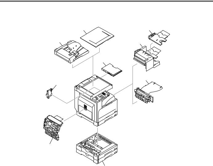
1.1.1 Pickup/ Delivery /Original Handling Accessories System Configuration (1-cassette/Platen cover (option) model)
The configuration is as shown in the following figure:
[4]
[3]
[2]
[1]
[5]
[10]
[9]
[6]
[8]
[7]
[7]
[6]
F-1-1
[1]DADF-P2
[2]Platen Cover Type J
[3]Finisher-U2
[4]Additional Finisher Tray-C1
[5]Inner 2-way Tray-E2
|
[6] |
Cassette Feeding Module-S1 |
*1 |
|
[7] |
Cassette Feeding Module-T1 |
*1 |
[8]Duplex Unit-A1
|
[9] |
Power Supply Kit-Q1 |
*2 |
[10]Document Tray-J1
*1: A Cassette feeding module-S1 can be placed on the Cassette feeding module-T1 to use these cassette units as a 3-stage cassette unit. *2: This accessory is required when the Finisher-U2, Cassette feeding module-T1 is installed.
1-1

Chapter 1
1.1.2 Pickup/ Delivery /Original Handling Accessories System Configuration (1-cassette/Platen cover (standard) model)
The configuration is as shown in the following figure:
[4]
[3]
[2]
[1]
[5]
[10]
[9]
[6]
[8]
[7]
[7]
[6]
F-1-2
[1]DADF-P2
|
[2] |
Platen Cover Type J |
*1 |
[3]Finisher-U2
[4]Additional Finisher Tray-C1
[5]Inner 2-way Tray-E2
|
[6] |
Cassette Feeding Module-S1/S2*2 |
*3 |
|
[7] |
Cassette Feeding Module-T1/T2*2 |
*3 |
[8]Duplex Unit-A1
|
[9] |
Power Supply Kit-Q1 |
*4 |
[10]Document Tray-J1
*1: This accessory comes standard.
*2: Only for China, this machine uses the cassette feeding module-S2 and the cassette feeding module-T2.
*3: A Cassette feeding module-S1 can be placed on the Cassette feeding module-T1 (A Cassette feeding module-S2 can be placed on the Cassette feeding moduleT2) to use these cassette units as a 3-stage cassette unit.
*4: This accessory is required when the Finisher-U2, Cassette feeding module-T1/T2 is installed.
1-2
Chapter 1
1.1.3 Pickup/ Delivery /Original Handling Accessories System Configuration (2-cassette/Duplex unit (option) model)
The configuration is as shown in the following figure:
|
[2] |
[4] |
|
[1] |
[3] |
|
[9] |
|
|
[5] |
|
|
[8] |
[7]
[6]
F-1-3
[1]DADF-P2
|
[2] |
Platen Cover Type J |
*1 |
[3]Finisher-U2
[4]Additional Finisher Tray-C1
[5]Inner 2-way Tray-E2
[6]Cassette Feeding Module-T2
|
[7] |
Duplex Unit-A1 |
*1 |
|
[8] |
Power Supply Kit-Q1 |
*2 |
[9]Document Tray-J1
*1: This accessory comes standard.
*2: This accessory is required when the Finisher-U2, Cassette feeding module-T2 is installed.
1-3

Chapter 1
1.1.4 Pickup/ Delivery /Original Handling Accessories System Configuration (2-cassette/Duplex unit (standard) model)
The configuration is as shown in the following figure:
|
[2] |
[4] |
|
[1] |
[3] |
|
[9] |
|
|
[5] |
|
|
[8] |
[7]
[6]
F-1-4
[1]DADF-P2
[2]Platen Cover Type J
[3]Finisher-U2
[4]Additional Finisher Tray-C1
[5]Inner 2-way Tray-E2
[6]Cassette Feeding Module-T1
[7]Duplex Unit-A1
|
[8] |
Power Supply Kit-Q1 |
*1 |
[9]Document Tray-J1
*1: This accessory is required when the Finisher-U2, Cassette feeding module-T1 is installed.
1-4

Chapter 1
1.1.5 Reader Heater/ Cassette Heater System Configuration
The configuration is as shown in the following figure:
[1]
|
[3] |
[2] |
|
|
F-1-5 |
||
|
[1] |
Reader Heater |
*1 |
|
[2] |
Cassette Heater |
*1 |
[3]Heater PCB
*1: To operate the heaters, a heater PCB is required. These parts are supplied as service parts, not the standard items.
1-5

Chapter 1
1.1.6 Printing/Transmitting Accessories System Configuration
This machine does not allow the print function and the transmission function to be added.
1.2 Product Specifications
1.2.1 Names of Parts
1.2.1.1 External View (1-cassette model)
[1]
|
[11] |
[2] |
||
|
[12] |
|||
|
[10] |
[3] |
||
|
[4] |
|||
|
[9] |
|||
|
[5] |
|||
|
[8] |
[6] |
[16] |
|
|
[7] |
[15] |
||
|
F-1-6 |
|||
|
[1] |
Copyboard cover (*1) |
[9] |
Left door |
|
[2] |
Reader front cover |
[10] |
Left cover (rear) |
|
[3] |
Control panel |
[11] |
Reader left cover |
|
[4] |
Delivery tray |
[12] |
Reader right cover |
|
[5] |
Front cover |
[13] |
Reader rear cover |
|
[6] |
Cassette 1 |
[14] |
Rear cover |
|
[7] |
Left cover (front) |
[15] |
Right cover (upper) |
|
[8] |
Manual feed tray |
[16] |
Right cover (lower) |
*1: This accessory comes optionally with the iR2320L (Latin American countries model), iR2318L (Korean model). Other models are standard.
1.2.1.2 External View (2-cassette model)
|
[1] |
||||
|
[12] |
[2] |
|||
|
[3] |
[13] |
|||
|
[11] |
||||
|
[4 ] |
||||
|
[10] |
||||
|
[5] |
||||
|
[9] |
[6] |
|||
|
[8] |
[7] |
[18] |
||
|
F-1-7 |
||||
|
[1] |
Copyboard cover |
[9] |
Left door |
|
|
[2] |
Reader front cover |
[10] |
Left cover (rear) |
|
|
[3] |
Control panel |
[11] |
Reader left cover |
|
|
[4] |
Delivery tray |
[12] |
Reader right cover |
|
|
[5] |
Front cover |
[13] |
Reader rear cover |
|
|
[6] |
Cassette 1 |
[14] |
Rear cover |
[14]
 [15]
[15]
[16]
[17]
1-6
Chapter 1
|
[7] |
Left cover (front) |
[15] |
Right cover (upper) |
|
[8] |
Manual feed tray |
[16] |
Right cover (lower) |
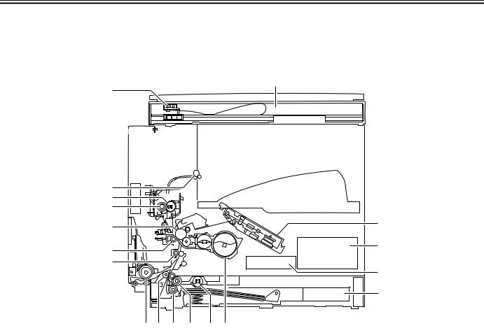
1.2.1.3 Cross-Section
[2]
[1]
[18]
[17]
[16]
[15]
[14]
[13]
|
[12] [11] [10] [9] |
[8] [7] |
||
|
F-1-8 |
|||
|
[1] |
CIS unit |
[10] |
Separation roller |
|
[2] |
Reader unit |
[11] |
Vertical path roller |
|
[3] |
Laser scanner unit |
[12] |
Manual feed pickup roller |
|
[4] |
DC power supply PCB |
[13] |
Registration roller |
|
[5] |
HVT PCB |
[14] |
Transfer roller |
|
[6] |
Cassette |
[15] |
Drum unit |
|
[7] |
Toner bottle |
[16] |
Pressure roller |
|
[8] |
Pickup roller |
[17] |
Fixing film unit |
|
[9] |
Feed roller |
[18] |
Delivery roller |
1.2.2 Using the Machine
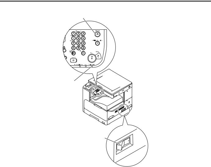
1.2.2.1 Turning On the Power Switch (1-cassette model)
1-7
Chapter 1
The machine possesses 2 power switches: main power switch and control power switch. Normally (i.e., unless the machine is in a sleep state), the machine will be supplied with power when you turn on its main power switch.
[1]
[2]
[3]
F-1-9
[1]Control panel power switch [2]Main power lamp
[3]Main power switch
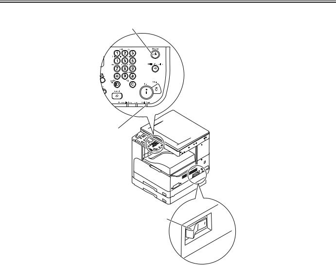
1.2.2.2 Turning On the Power Switch (2-cassette model)
1-8
Chapter 1
The machine possesses 2 power switches: main power switch and control power switch. Normally (i.e., unless the machine is in a sleep state), the machine will be supplied with power when you turn on its main power switch.
[1]
[2]
[3]
F-1-10
[1]Control panel power switch [2]Main power lamp
[3]Main power switch
1.2.2.3 When Turning Off the Main Power Switch (1-cassette model)
1-9

Chapter 1
<During printing or fax data transmission/reception>
Be sure to operate the main power switch while the Processing/Data lamp on the control panel is not lit.
(Turning off the main switch during printing or fax data transmission/reception can erase the data being processed.)
F-1-11
<During downloading>
Do not turn off the power switch or ON/OFF switch on the control panel.
(Turning off the main power switch during downloading can make this machine inoperative.)
F-1-12
1-10
![]()
Chapter 1
1.2.2.4 When Turning Off the Main Power Switch (2-cassette model)
<During printing or fax data transmission/reception>
Be sure to operate the main power switch while the Processing/Data lamp on the control panel is not lit.
(Turning off the main switch during printing or fax data transmission/reception can erase the data being processed.)
F-1-13
1-11

Chapter 1
<During downloading>
Do not turn off the power switch or ON/OFF switch on the control panel.
(Turning off the main power switch during downloading can make this machine inoperative.)
F-1-14
1.2.2.5 Control Panel
|
[1] [2] [3] |
[4] [5] |
[6] [7] [8] |
[9] |
[10][11] |
|||||||||||||||||||||||||||||||||||
|
[30] [29] [28] [26][25] [23][22] [19] [17] [15] [14] [13] [12] |
|||||||
|
[27] |
[24] |
[18] |
[16] |
||||
|
[21] [20] |
|||||||
|
F-1-15 |
|||||||
|
[1] |
System Monitor key |
[16] |
Clear key |
||||
|
[2] |
SCAN key |
[17] |
Processing/Date Indicator |
||||
|
[3] |
COPY key |
[18] |
ID key |
||||
|
[4] |
Back key |
[19] |
Reset key |
||||
|
[5] |
Upper/Lower/Left/Right arrow key |
[20] |
Tone key |
||||
|
[6] |
OK key |
[21] |
Paper Select key |
||||
|
[7] |
LCD display |
[22] |
Frame Erase key |
||||
|
[8] |
View Settings key |
[23] |
Copy Ratio key |
||||
|
[9] |
Numeric keys |
[24] |
2-Page Separation key |
||||
|
[10] |
Control Panel Power Switch |
[25] |
Image Quality key |
||||
|
[11] |
Additional Functions key |
[26] |
Finishing key |
1-12

Chapter 1
|
[12] |
Stop key |
[27] |
Density key |
|
[13] |
Start key |
[28] |
Different Size Originals key |
|
[14] |
Main Power Indicator |
[29] |
Image Combination key |
|
[15] |
Error Indicator |
[30] |
2-Sided key |
Key names may be different depending on the countries or area of destination.
1.2.3 User Mode Items
1.2.3.1 Audible Tones
|
Additional Functions |
Settings |
|
Entry Tone |
Off, ON(*) |
|
Error Tone |
Off, ON(*) |
|
Scan Done Tone |
Off, ON, For Error Only(*) |
|
Print Done Tone |
Off, ON, For Error Only(*) |
* Factory setting (It may be different depending on the countries or region of destination.)
1.2.3.2 Common Settings
|
Additional Functions |
Settings |
|
|
Initial Function |
Copy(*), Scan |
|
|
Contrast |
-2 to +2; -/+0(*) |
|
|
Invert Screen Colors |
Off(*), On |
|
|
Auto Clear Setting |
Initial Function(*), Selected Function |
|
|
Toner Save Mode |
Off(*), Low, High |
|
|
Print Density |
-4 to +4; -/+0(*) |
|
|
Auto Drawer Select. |
Copy: Stack Bypass (Off(*), On), Drawer 1 (Off, On(*)), Drawer 2 (Off, On(*)), |
|
|
Drawer 3 (Off, On(*)), Drawer 4 (Off, On(*)) |
||
|
Printer: Drawer 1 (Off, On(*)), Drawer 2 (Off, On(*)), Drawer 3 (Off, On(*)), |
||
|
Drawer 4 (Off, On(*)) |
||
|
Other: Stack Bypass (Off(*), On), Drawer 1 (Off, On(*)), Drawer 2 (Off, On(*)), |
||
|
Drawer 3 (Off, On(*)), Drawer 4 (Off, On(*)) |
||
|
Register Paper Type |
Drawer 1: Plain(*), Recycled, Color, 3-hole punch, Bond, Heavy Paper 1 |
|
|
Drawer 2: Plain(*), Recycled, Color, 3-hole punch, Bond, Heavy Paper 1 |
||
|
Drawer 3: Plain(*), Recycled, Color, 3-hole punch, Bond, Heavy Paper 1 |
||
|
Drawer 4: Plain(*), Recycled, Color, 3-hole punch, Bond, Heavy Paper 1 |
||
|
Tray Designation |
Tray A: Copy (Off, On(*)), Printer (Off, On(*)), |
Other (Off, On(*)) |
|
Tray B: Copy (Off, On(*)), Printer (Off, On(*)), |
Other (Off, On(*)) |
|
|
Stand. Stack Bypass. |
Off(*), On: |
|
|
Paper Size (LTR(*), LTRR, LGL, STMT, STMTR, EXEC, 11 x 17, Custom Size, |
||
|
COM10, Monarch, DL, ISO-C5, ISO-B5, A4, A4R, A3, A5, A5R, B4, B5, B5R) |
||
|
Paper Type (Plain(*), Recycled, Color, 3-hole punch, Bond, Heavy Paper 1, Heavy |
||
|
Paper 2, Heavy Paper 3, Transparency, Labels) |
||
|
Paper Size (LTR(*), LTRR, LGL, STMT, STMTR, EXEC, 11 x 17, Custom Size, |
||
|
COM10, Monarch, DL, ISO-C5, ISO-B5, A4, A4R, A3, A5, A5R, B4, B5, B5R) |
||
|
Paper Type (Plain(*), Recycled, Color, 3-hole punch, Bond, Heavy Paper 1, Heavy |
||
|
Paper 2, Heavy Paper 3, Transparency, Labels) |
||
|
Paper Feed Switch |
Stack Bypass (Speed Priority(*), Print Side), Drawer 1 (Speed Priority(*), Print |
|
|
Side), Drawer 2 (Speed Priority(*), Print Side), Drawer 3 (Speed Priority(*), Print |
||
|
Side), Drawer 4 (Speed Priority(*), Print Side) |
||
|
Language Switch |
Chinese (Simplified), English(*), French, Japanese, Korean, Portuguese, Spanish |
|
|
Dirty Feeder Error |
Off, On(*) |
|
|
Remote Scan Compress |
High Ratio, Normal(*), Low Ratio |
|
|
Remote Scan Gammma |
1.0, 1.4, 1.8(*), 2.2 |
|
|
K/B Size Originals*1 |
Use 8K/16K Format, Use B4/B5 Format(*) |
1-13

Chapter 1
|
Additional Functions |
Settings |
|
Inch/Millimeter Switch |
mm, inch(*) |
|
Paper Size Group |
AB, Inch(*), A |
|
Initialize Common |
Select <Yes> or <No>. |
* Factory setting (It may be different depending on the countries or region of destination.) *1 This item may be omitted depending on the countries or area of destination.
1.2.3.3 Copy Settings
|
Additional Functions |
Settings |
|
Image Orientation |
Off(*), On |
|
Auto Orientation |
Off, On(*) |
|
Standard Settings |
|
|
No. of Copies |
1(*) — 99 |
|
Density |
Auto(*), Manual (-4 to +4) |
|
Image Quality |
Text(*), Text/Photo, Photo |
|
2-Sided |
Off(*), 1 -> 2-Sided, 2 -> 2-Sided, 2 -> 1-Sided, |
|
Book -> 2-Sided, Layout Settings |
|
|
Copy Ratio |
Zoom (25 — 400%), MAX. (400%), STMT -> 11 x 17 (200%), LTR -> 11 x 17 |
|
(129%), LGL -> 11 x 17 (121%), 1:1 (100%)(*), LGL -> LTR (78%), 11 x 17 -> |
|
|
LGL (73%), 11 x 17 -> LTR (64%), 11 x 17 -> STMT (50%), MIN. (25%) |
|
|
Paper Select |
Auto(*), Stack Bypass, Drawer 1, Drawer 2, Drawer 3, Drawer 4 |
|
Image Combination |
Off(*), 2 on 1, 4 on 1, ID Card Copy |
|
Differ. Size Orig |
AB/inch Size group selected: |
|
Off(*), Same Width, Different Width |
|
|
A Size group selected: |
|
|
Off(*), On |
|
|
Finishing |
Collate, Rotate + Collate, Group(*), Rotate + Group, Offset + Collate, Offset + |
|
Group, Staple |
|
|
2-Page Separation |
Off(*), On |
|
Frame Erase |
Off(*), Org. Frame Erase, Book Frame Erase, Binding Erase, Options |
|
Sharpness |
Lowest (leftmost) to Highest (rightmost), Middle (center)(*) |
|
Initialize Copy Set. |
Yes(*), No |
* Factory setting (It may be different depending on the countries or region of destination.)
1.2.3.4 Printer Settings
|
Additional Functions |
Settings |
|
Default Papersize |
LTR(*), LTRR, LGL, STMTR, EXEC, A4, A4R, A3, A5R, B4, B5, B5R, |
|
COM10, Monarch, DL, ISO-C5, ISO-B5 |
Default Papertype
2-Sided Print Quality
Image Refinement
Density
Toner Saver
Page Layout
Binding
Margin
Finishing
Error Time Out
Auto Size Detection
Initialize Printer
Plain(*), Recycled, Color, 3-hole punch, Bond, Heavy Paper, Tracing Paper, Transparency, Labels
Off(*), On
On(*), Off
-4 to +4; -/+0(*) Off(*), On
Long Edge(*), Short Edge
Inch: -01.97″ to +01.97″; 00.00″ mm: -50.0 mm to +50.0 mm; 0.0 mm
Collate, Rotate + Collate, Group(*), Rotate +Group, Offset +Collate, Offset + Group, Staple
On(*)(1 to 300 sec), Off; 15 sec(*)
Off(*), On
Select <Yes> or <No>.
* Factory setting (It may be different depending on the countries or region of destination.)
1-14

Chapter 1
1.2.3.5 Timer Settings
|
Additional Functions |
Settings |
|
Auto Sleep Time |
Off, On ( 3 to 30 minutes; 5 min(*) in one minute increments) |
|
Auto Clear Time |
Off, On ( 1 to 9 minutes; 2 min(*) in one minute increments) |
* Factory setting (It may be different depending on the countries or region of destination.)
1.2.3.6 Adjustment/Cleaning
|
Additional Functions |
Settings |
|
Clean Trans. Roller |
Select <Yes> or <No>. |
|
Drum Cleaning |
Select <Yes> or <No>. |
|
Fixing Unit Cleaning |
Select <Yes> or <No>. |
|
Feeder Cleaning |
Select <Yes> or <No>. |
|
Bond Sp. Processing |
Off(*), On |
|
Special Mode M |
Low, Standard(*), High |
|
Special Mode N |
Off(*), On |
|
Special Mode O |
Stack Bypass: Off(*), On |
|
Drawer: Off(*), On |
|
|
Special Mode P |
Off(*), On |
|
Special Mode S |
Off(*), Speed Priority1, Speed Priority 2 |
|
Rotate Collate Adj. |
Speed Priority 1(*), Speed Priority 2, Image Priority |
|
Dirty Feeder Adj. |
Off(*), On |
* Factory setting (It may be different depending on the countries or region of destination.)
1.2.3.7 Report Settings
|
Additional Functions |
Settings |
|
Print List |
User’s Data List: Select <Yes> or <No>. |
1.2.3.8 System Settings
|
Additional Functions |
Settings |
|
System Manager Set. |
System Manager ID, System Manager |
|
Device Info Settings |
Device Name, Location |
|
Dept. ID Management |
Off(*), On: |
|
Reg./Edit Dept. ID: |
|
|
Department ID, Password, Limit Settings, Erase |
|
|
Page Totals: |
|
|
View Page Totals, Clear All Totals, Print List |
|
|
Allow Unkn. ID Print: Off, On(*) |
|
|
Allow Unkn. ID Scan: Off, On(*) |
|
|
User ID Management |
Off(*), On |
|
Network Settings |
TCP/IP Settings, SNMP Settings, Ethernet Driver, Startup Time Set. |
|
Remote UI On/Off |
Off, On(*) |
|
Job Log Display |
Off, On(*) |
|
Use USB Device |
Off, On(*) |
|
Update Firmware |
This function is only used when the firmware needs to be updated. |
* Factory setting (It may be different depending on the countries or region of destination.)
1-15

Chapter 1
1.2.3.9 Network Settings
|
Item |
Setting Description |
Default Setting |
|
|
TCP/IP Settings |
|||
|
IPv4 Settings: IP Address Settings |
|||
|
IP Address Auto. |
|||
|
DHCP |
On/Off |
Off |
|
|
BOOTP |
On/Off |
Off |
|
|
RARP |
On/Off |
Off |
|
|
IP Address |
IP address |
0.0.0.0 |
|
|
Subnet Mask |
IP address |
0.0.0.0 |
|
|
Gateway Address |
IP address |
0.0.0.0 |
|
|
IPv4 Settings |
|||
|
PING Command |
IP address |
0.0.0.0 |
|
|
IPv4 Settings |
|||
|
On/Off |
|||
|
IP Address Range |
Up to four IPv4 addresses or ranges of IPv4 |
Off |
|
|
addresses can be stored. (Permit/Reject) |
|||
|
IPv4 Settings: DNS Settings |
|||
|
DNS Server Settings |
|||
|
Primary DNS Server |
IP address |
0.0.0.0 |
|
|
Secondary DNS Server |
IP address |
0.0.0.0 |
|
|
DNS Host/Domain |
|||
|
Host Name |
47 Characters maximum |
(‘Canon’ + the last six digits of the machine’s MAC |
|
|
address) |
|||
|
Domain Name |
47 Characters maximum |
(NULL) |
|
|
DNS Dynamic Update |
On/Off |
Off |
|
|
IPv6 Settings |
|||
|
Use IPv6 |
On/Off |
Off |
|
|
Stateless Address |
On/Off |
On |
|
|
IPv6 Settings: Manual Address Set. |
|||
|
Use Manual Address |
On/Off |
Off |
|
|
Manual Address |
39 Characters maximum |
0:0:0:0:0:0:0:0 |
|
|
Prefix Length |
0 to 128 |
64 |
|
|
Default Router Addr. |
39 Characters maximum |
0:0:0:0:0:0:0:0 |
|
|
IPv6 Settings |
|||
|
Use DHCPv6 |
On/Off |
Off |
|
|
IPv6 Settings: PING Command |
|||
|
IPv6 Address |
39 Characters maximum |
0:0:0:0:0:0:0:0 |
|
|
Host Name |
48 Characters maximum |
(NULL) |
|
|
IPv6 Settings |
|||
|
On/Off |
|||
|
IP Address Range |
Up to 4 IPv6 addresses, ranges of IPv6 |
Off |
|
|
addresses, or IPv6 address prefixes can be |
|||
|
stored. (Permit/Reject) |
|||
|
IPv6 Settings: DNS Settings |
|||
|
DNS Server Settings |
|||
|
Primary DNS Server |
IP address |
0.0.0.0 |
|
|
Secondary DNS Server |
IP address |
0.0.0.0 |
|
|
DNS Host/Domain |
On/Off |
On |
|
|
Use IPv4 Host/Domain |
On/Off |
Off |
|
|
Host Name |
47 Characters maximum |
(‘Canon’ + the last six digits of the machine’s MAC |
|
|
address) |
|||
|
Domain Name |
47 Characters maximum |
(NULL) |
|
|
DNS Dynamic Update |
On/Off |
Off |
|
|
Reg. Manual Address |
On/Off |
Off |
|
|
Register Stateful |
On/Off |
Off |
|
|
WINS Configuration |
|||
|
WINS Configuration |
On/Off |
Off 0.0.0.0 |
|
|
LPD Print Settings |
1-16

Chapter 1
|
Item |
Setting Description |
Default Setting |
|
LPD Print Settings |
On/Off |
On |
|
RAW Print Settings |
||
|
RAW Print Settings |
On/Off |
On |
|
Use Bidirectional |
On/Off |
Off |
|
Use HTTP |
||
|
Use HTTP |
On/Off |
On |
|
Port Number Settings |
||
|
LPD |
Port Number |
515 |
|
RAW |
Port Number |
9100 |
|
HTTP |
Port Number |
80 |
|
SNMP |
Port Number |
161 |
|
RX MAC Address Set. |
||
|
On/Off |
||
|
RX MAC Address Set. |
MAC addresses (A maximum of five |
Off |
|
addresses can be registered) |
||
|
SNMP Settings |
||
|
SNMP Settings |
On/Off |
On |
|
Community Name 1 |
Community Name |
public |
|
Community Name 2 |
Community Name |
(NULL) |
|
Writable SNMP 1 |
On/Off |
On |
|
Writable SNMP 2 |
On/Off |
Off |
|
Print Manage. Info |
On/Off |
On |
|
Ethernet Driver |
||
|
Auto Detect |
On/Off |
On |
|
Communication Mode |
Full Duplex/Half Duplex |
Full Duplex |
|
Ethernet Type |
10 Base-T/100 Base-TX |
|
|
Startup Time Settings |
||
|
Startup Time Settings |
0 to 300 sec |
0 sec |
* Factory setting (It may be different depending on the countries or region of destination.)
1.2.4 Maintenance by the User 1.2.4.1 User Maintenance Items
|
No. |
Item |
Maintenance cycle |
Remarks |
|
[1] |
Pressure plate cleaning |
As required |
|
|
[2] |
Copyboard glass(large/small*1) cleaning |
As required |
|
|
[3] |
Copyboard holder*1 (jump board) |
As required |
|
|
[4] |
Fixing pressure roller cleaning |
As required |
Clean every 10000 sheets |
|
[5] |
Exterior cleaning |
As required |
|
|
[6] |
Transfer roller cleaning |
As required |
|
|
[7] |
Drum cleaning |
As required |
|
|
[8] |
Toner replenishment (toner bottle replacement) |
When the relevant error code appears |
|
*1 Only for ADF equipped model
1.2.4.2 Cleaning
The parts that should be cleaned by the customer to maintain the design performance and the cleaning method are described below. The service engineer should instruct the customer to clean the machine at regular intervals (once a month).
1. Pressure Plate
Clean the pressure plates [1] with a cloth dampened with water or neutral detergent and squeezed hard, and then wipe it with a dry soft cloth.
1-17

Chapter 1
 [1]
[1]
F-1-16
2. Document Glass/Vertical Size Plate
Clean the document glass [1] and vertical size plate [2] with a cloth dampened with water or neutral detergent and squeezed hard, and then wipe them with a dry soft cloth.
When an ADF is installed, clean is document glass (small) [3] and glass holder [4] in the same manner.
[1]
[3]
[2]
[4]
F-1-17
3. Cleaning the Fixing Pressure Roller
If white streaks are seen on the printed paper, the fixing pressure roller can be dirty. If white streaks are seen on the printed paper, clean the fixing pressure roller in the user mode. Be sure to clean the fixing pressure roller after replacing the toner bottle.
 When cleaning the fixing pressure roller, manually feed A4/LTR paper.
MEMO:
The time required for cleaning is about 100 seconds.
1)Press the Additional Functions key to enter the user mode.
2)Using the arrow keys, display the «Adjustment/Cleaning» menu.
3)Press the OK key.
4)Using the arrow keys, select «Fixing Unit Cleaning». Select «Yes» and then press the OK key.
5)Press the OK key. A cleaning pattern will be printed.
6)Open the manual feed tray.
F-1-18
7) Place the cleaning pattern printed in step 5 in the manual feed tray with «V» up.
1-18

Chapter 1
F-1-19
 The LCD display returns «Start Cleaning».
9)Select «Yes» and then press the OK key. Cleaning will start.
4. Cleaning the Transfer Roller
If the reverse side of the printed paper is stained, the transfer roller can be dirty. If the reverse side of the printed paper is stained, clean the transfer roller in the user mode.
1)Press the Additional Functions key to enter the user mode.
2)Using the arrow keys, display the «Adjustment/Cleaning».
3)Press the OK key.
4)Using the arrow keys, select «Clean Trans. Roller». Next, press the OK key. Cleaning will start.
5. Cleaning the Drum
If the quality of the printer image is poor, the drum can be dirty. If this symptom occurs, clean the drum in the user mode.
1)Press the Additional Functions key to enter the user mode.
2)Using the arrow keys, display the «Adjustment/Cleaning» menu.
3)Press the OK key.
4)Using the arrow keys, select «Drum Cleaning». Next, press the OK key. Cleaning will start.
1.2.5 Safety
1.2.5.1 Safety of the Laser Light
Laser light can prove to be hazardous to the human body. The machine’s laser unit is fully enclosed in a protective housing and external covers so that its light will not escape outside as long as the machine is used normally.
1.2.5.2 CDRH Regulations
The Center for Devices and Radiological Health of the US Food and Drum Administration put into force regulations concerning laser products on August 2, 1976. These regulations apply to laser products manufactured on and after August 1, 1976, and the sale of laser products not certified under the regulations is banned within the Untied States. The label shown here indicates compliance with the CDRH regulations, and its attachment is required on all laser products that are sold in the United States.
CANON
30-2, SHIMOMARUKO, 3-CHOME, OHTAKU, TOKYO, 146, JAPAN.
MANUFACTURED:
THIS PRODUCT CONFORMS WITH DHHS RADIATION
PERFORMANCE STANDARD 21CFR CHAPTER 1
SUBCHAPTER J.
F-1-20
1.2.5.3 Handling the Laser Unit
1-19

Chapter 1
The laser scanner unit emits invisible laser light inside it. If exposed to laser light, the human eye can irreparably be damaged. Never attempt to disassemble the laser scanner unit. (It is not designed for servicing in the field.)
Warning labels are affixed to the top cover of the laser scanner unit and the inner cover inside the front cover of this machine.
F-1-21
1.2.5.4 Safety of Toner
The machine’s toner is a non-toxic material made of plastic, iron, and small amounts of dye.
Do not throw toner into fire. It may cause explosion.
Toner on Clothing or Skin
1.If your clothing or skin has come into contact with toner, wipe it off with tissue; then, wash it off with water.
2.Do not use warm water, which will cause the toner to jell and fuse permanently with the fibers of the cloth.
3.Do not bring toner into contact with plastic material. It tends to react easily.
1.2.5.5 Point to Note about Fire
It is dangerous to throw lithium batteries and parts and components containing flammable substances, such as cartridges, etc., into fire. Such parts and components must be disposed of in accordance with local laws and regulations.
1.2.6 Product Specifications
1.2.6.1 Product Specifications
|
Copyboard |
stream reading, fixed reading |
|
Body |
desktop |
|
Light source type |
LED array (CIS) |
1-20
![]()
Chapter 1
|
Photosensitive medium |
OPC drum (30-mm dia.) |
|
Image reading method |
CCD (CIS) |
|
Reproduction method |
indirect electrostatic |
|
Exposure method |
by laser light |
|
Charging method |
by AC charging roller |
|
Development method |
1-component toner projection |
|
Transfer method |
by transfer roller |
|
Separation method |
by curvature + static eliminator |
|
Cassette pickup method |
retard |
|
Multifeeder pickup method |
dual processing |
|
Drum cleaning method |
by cleaning blade |
|
Fixing method |
on-demand |
|
Delivery method |
face-down |
|
Reproduction ratio |
25% to 400% |
|
Warm-up time |
approx. 13sec |
|
Image margin (leading edge) |
3.0 -/+1.5 mm |
|
Image margin (trailing edge) |
5.0 -/+2.0 mm |
|
Image margin (left/right) |
left edge: 3.0 -/+2.0 mm |
|
right edge: 0.5 mm or more |
|
|
Non-image width (leading edge) |
3.0 -/+2.0 mm |
|
Non-image width (trailing edge) |
5.0 -/+2.0mm |
|
Non-image width (left/right) |
3.0 -/+2.0mm(left side only) |
|
Number of gradations |
256 gradations |
|
Reading resolution |
600 x 600 dpi |
|
Printing resolution |
600dpi x 600dpi |
|
First print time |
Book mode: 7.9 sec or less |
|
Cassette capacity |
250sheets (80 g/m2) |
|
Multifeeder tray capacity |
100 sheets (80 g/m2) (B4/LGL or less, 64 g/m2) |
|
80 sheets (80 g/m2) (B4/LGL or less, 80 g/m2) |
|
|
50 sheets (B4/LGL or more, 64 g/m2, 80 g/m2) |
|
|
50 sheets (heavy paper (105 g/m2), OHP) |
|
|
10 sheets (envelope) |
|
|
1 sheet (label) |
|
|
Continuous reproduction |
1 to 99 sheets |
|
Toner type |
magnetic negative toner |
|
Original type |
sheet, book |
|
Maximum original size |
A3/LDR |
|
Original size detection function |
by reflection type sensor (if equipped with original detection function) |
|
Sleep mode |
yes |
|
Option |
See the system configuration chart. |
|
Operating environment |
15 to 27.5 deg C |
|
(temperature range) |
|
|
Operating environment |
25% to 75% |
|
(humidity range) |
|
|
Operating environment |
0.6 to 1.0 atm |
|
(atmospheric pressure) |
|
|
Noise |
iR2422 series: 66.7 dB or less |
|
iR2420/2320 series: 66.0 dB or less |
|
|
iR2318 series: 65.3 dB or less |
|
|
Power supply rating |
120/230 V |
|
Power consumption (maximum) |
120V model: 1406 W or less |
|
230V model: 1348 W or less |
|
|
Power consumption |
120V model (full option): |
|
sleep mode: 3.0 W (reference only) / continuous printing: 527 |
|
|
W(reference only) |
|
|
230V model (full option): |
|
|
sleep mode: 3.3 W (reference only) / continuous printing: 509 W |
|
|
(reference only) |
|
|
Ozone |
1.5mg/h |
|
Dimensions |
[Copyboard cover type] |
|
1-stage cassette model: 622mm x 638mm x 580.4mm (W x D x H) |
|
|
2-stage cassette model: 622mm x 638mm x 665.4mm (W x D x H) |
|
|
Weight |
[Copyboard cover type] |
|
1-stage cassette model: approx. 37.9 kg |
|
|
2-stage cassette model (standard equipement with Duplex unit): approx. |
|
|
46.2 kg |
|
1.2.7 Function List
1.2.7.1 Printing Speed (iR2422series)
1-21

Chapter 1
|
Paper size |
Single-sided |
|||
|
Casette feed |
Manual feed |
|||
|
Plain paper |
A4 |
22 |
22 |
|
|
A5 |
23 |
23 |
||
|
A5R |
— |
13 |
||
|
B5 |
20 |
20 |
||
|
B5R |
12 |
12 |
||
|
A4R |
11 |
11 |
||
|
B4 |
9 |
9 |
||
|
A3 |
10 |
10 |
||
|
STMT |
15 |
15 |
||
|
STMTR |
— |
13 |
||
|
EXE |
— |
21 |
||
|
LTR |
22 |
22 |
||
|
LTRR |
11 |
11 |
||
|
LGL |
10 |
10 |
||
|
LDR |
10 |
10 |
||
|
8K |
9 |
9 |
||
|
16KR |
10 |
10 |
||
|
16K |
20 |
20 |
||
|
Heavy paper 1/2 |
A4 |
12(10) |
12(10) |
|
|
(Heavy paper 3) |
||||
|
A5 |
13(11) |
13(11) |
||
|
A5R |
— |
10(7) |
||
|
B5 |
12(10) |
12(10) |
||
|
B5R |
9(6) |
9(6) |
||
|
A4R |
10(8) |
10(8) |
||
|
B4 |
8(6) |
8(6) |
||
|
A3 |
8(7) |
8(7) |
||
|
STMT |
11(7) |
11(7) |
||
|
STMTR |
— |
9(6) |
||
|
EXE |
— |
12(10) |
||
|
LTR |
11(10) |
11(10) |
||
|
LTRR |
9(8) |
9(8) |
||
|
LGL |
8(5) |
8(5) |
||
|
LDR |
8(7) |
8(7) |
||
|
8K |
7(5) |
7(5) |
||
|
16KR |
8(6) |
8(6) |
||
|
16K |
12(10) |
12(10) |
||
|
Bond paper |
A4 |
7 |
7 |
|
|
A5 |
5 |
5 |
||
|
A5R |
— |
4 |
||
|
B5 |
6 |
6 |
||
|
B5R |
4 |
4 |
||
|
A4R |
4 |
4 |
||
|
B4 |
5 |
5 |
||
|
A3 |
5 |
5 |
||
|
STMT |
4 |
4 |
||
|
STMTR |
— |
4 |
||
|
EXE |
— |
6 |
||
|
LTR |
7 |
7 |
||
|
LTRR |
4 |
4 |
||
|
LGL |
3 |
3 |
||
|
LDR |
5 |
5 |
||
|
8K |
5 |
5 |
||
|
16KR |
3 |
3 |
||
|
16K |
6 |
6 |
||
|
OHP |
A4 |
— |
20 |
|
|
LTR |
— |
20 |
||
|
Envelope |
Monarch |
— |
4 |
|
|
COM10 |
— |
4 |
||
|
ISO-B5 |
— |
4 |
||
|
ISO-C5 |
— |
4 |
||
|
DL |
— |
4 |
||
1-22

Chapter 1
ï‚ë´ÅF
ЕEеŽйЬЗХеŽйЬ1ЗэеŽйЬ2ЗГнlЗšй¶ЗµЕA( )м‡ЗХеŽйЬ3ЗГнlЗšй¶З²ЕB ЕEЙJЙZЙbЙgггйЬЕAйЛз²ЗµггйЬЕAЙIЙvЙVЙбЙмЗГЙJЙZЙbЙgЙЬЙjЙbЙgЗ©ЗБЗГЗ¢З³ЗНЗГггйЬиšеиЗЭЗ‡ЕAЙRЙsЕ[ЙXЙsЕ[ЙhЗХи„гLЗ…мШЗ¹ЕB ЕEнЛнЦдМЗГв²мxЕAуpйЬЙTЙCЙYЗ…ЗКЗЛЙRЙsЕ[ЙXЙsЕ[ЙhЗ™пœвªЗ²ЗИЕB
1.2.7.2 Printing Speed (iR2420/iR2320series)
|
Paper size |
Single-sided |
|||
|
Casette feed |
Manual feed |
|||
|
Plain paper |
A4 |
20 |
20 |
|
|
A5 |
23 |
23 |
||
|
A5R |
— |
13 |
||
|
B5 |
20 |
20 |
||
|
B5R |
12 |
12 |
||
|
A4R |
11 |
11 |
||
|
B4 |
9 |
9 |
||
|
A3 |
10 |
10 |
||
|
STMT |
15 |
15 |
||
|
STMTR |
— |
13 |
||
|
EXE |
— |
21 |
||
|
LTR |
20 |
20 |
||
|
LTRR |
11 |
11 |
||
|
LGL |
10 |
10 |
||
|
LDR |
10 |
10 |
||
|
8K |
9 |
9 |
||
|
16KR |
10 |
10 |
||
|
16K |
20 |
20 |
||
|
Heavy paper 1/2 |
A4 |
12(10) |
12(10) |
|
|
(Heavy paper 3) |
||||
|
A5 |
13(11) |
13(11) |
||
|
A5R |
— |
10(7) |
||
|
B5 |
12(10) |
12(10) |
||
|
B5R |
9(6) |
9(6) |
||
|
A4R |
10(8) |
10(8) |
||
|
B4 |
8(6) |
8(6) |
||
|
A3 |
8(7) |
8(7) |
||
|
STMT |
11(7) |
11(7) |
||
|
STMTR |
— |
9(6) |
||
|
EXE |
— |
12(10) |
||
|
LTR |
11(10) |
11(10) |
||
|
LTRR |
9(8) |
9(8) |
||
|
LGL |
8(5) |
8(5) |
||
|
LDR |
8(7) |
8(7) |
||
|
8K |
7(5) |
7(5) |
||
|
16KR |
8(6) |
8(6) |
||
|
16K |
12(10) |
12(10) |
||
|
Bond paper |
A4 |
7 |
7 |
|
|
A5 |
5 |
5 |
||
|
A5R |
— |
4 |
||
|
B5 |
6 |
6 |
||
|
B5R |
4 |
4 |
||
|
A4R |
4 |
4 |
||
|
B4 |
5 |
5 |
||
|
A3 |
5 |
5 |
||
|
STMT |
4 |
4 |
||
|
STMTR |
— |
4 |
||
|
EXE |
— |
6 |
||
|
LTR |
7 |
7 |
||
|
LTRR |
4 |
4 |
||
|
LGL |
3 |
3 |
||
|
LDR |
5 |
5 |
||
|
8K |
5 |
5 |
||
|
16KR |
3 |
3 |
||
|
16K |
6 |
6 |
||
|
OHP |
A4 |
— |
20 |
|
|
LTR |
— |
20 |
||
1-23

Chapter 1
|
Paper size |
Single-sided |
|||
|
Casette feed |
Manual feed |
|||
|
Envelope |
Monarch |
— |
4 |
|
|
COM10 |
— |
4 |
||
|
ISO-B5 |
— |
4 |
||
|
ISO-C5 |
— |
4 |
||
|
DL |
— |
4 |
||
Supplement:
—The above copy speed does not change irrespective of whether paper is supplied from the upper/lower cassette, the manual feed tray, or from the cassette feeding module.
—The copy speed may become down when the copies make continuously one minutes or more with the narrow width paper.
1.2.7.3 Printing Speed (iR2318series)
|
Paper size |
Single-sided |
|||
|
Casette feed |
Manual feed |
|||
|
Plain paper |
A4 |
18 |
18 |
|
|
A5 |
23 |
23 |
||
|
A5R |
— |
13 |
||
|
B5 |
20 |
20 |
||
|
B5R |
12 |
12 |
||
|
A4R |
11 |
11 |
||
|
B4 |
9 |
9 |
||
|
A3 |
10 |
10 |
||
|
STMT |
15 |
15 |
||
|
STMTR |
— |
13 |
||
|
EXE |
— |
21 |
||
|
LTR |
18 |
18 |
||
|
LTRR |
11 |
11 |
||
|
LGL |
10 |
10 |
||
|
LDR |
10 |
10 |
||
|
8K |
9 |
9 |
||
|
16KR |
10 |
10 |
||
|
16K |
20 |
20 |
||
|
Heavy paper 1/2 |
A4 |
12(10) |
12(10) |
|
|
(Heavy paper 3) |
||||
|
A5 |
13(11) |
13(11) |
||
|
A5R |
— |
10(7) |
||
|
B5 |
12(10) |
12(10) |
||
|
B5R |
9(6) |
9(6) |
||
|
A4R |
10(8) |
10(8) |
||
|
B4 |
8(6) |
8(6) |
||
|
A3 |
8(7) |
8(7) |
||
|
STMT |
11(7) |
11(7) |
||
|
STMTR |
— |
9(6) |
||
|
EXE |
— |
12(10) |
||
|
LTR |
11(10) |
11(10) |
||
|
LTRR |
9(8) |
9(8) |
||
|
LGL |
8(5) |
8(5) |
||
|
LDR |
8(7) |
8(7) |
||
|
8K |
7(5) |
7(5) |
||
|
16KR |
8(6) |
8(6) |
||
|
16K |
12(10) |
12(10) |
1-24

Chapter 1
|
Paper size |
Single-sided |
|||
|
Casette feed |
Manual feed |
|||
|
Bond paper |
A4 |
7 |
7 |
|
|
A5 |
5 |
5 |
||
|
A5R |
— |
4 |
||
|
B5 |
6 |
6 |
||
|
B5R |
4 |
4 |
||
|
A4R |
4 |
4 |
||
|
B4 |
5 |
5 |
||
|
A3 |
5 |
5 |
||
|
STMT |
4 |
4 |
||
|
STMTR |
— |
4 |
||
|
EXE |
— |
6 |
||
|
LTR |
7 |
7 |
||
|
LTRR |
4 |
4 |
||
|
LGL |
3 |
3 |
||
|
LDR |
5 |
5 |
||
|
8K |
5 |
5 |
||
|
16KR |
3 |
3 |
||
|
16K |
6 |
6 |
||
|
OHP |
A4 |
— |
20 |
|
|
LTR |
— |
20 |
||
|
Envelope |
Monarch |
— |
4 |
|
|
COM10 |
— |
4 |
||
|
ISO-B5 |
— |
4 |
||
|
ISO-C5 |
— |
4 |
||
|
DL |
— |
4 |
||
Supplement:
—The above copy speed does not change irrespective of whether paper is supplied from the upper/lower cassette, the manual feed tray, or from the cassette feeding module.
—The copy speed may become down when the copies make continuously one minutes or more with the narrow width paper.
1-25

Chapter 2 Installation

Contents
Contents
|
2.1 Making Pre-Checks…………………………………………………………………………………………………………………………………….. |
2-1 |
|
2.1.1 Selecting the Site of Installation ……………………………………………………………………………………………………………………………….. |
2-1 |
|
2.1.2 Before Starting the Work (120VCLA) ………………………………………………………………………………………………………………………. |
2-1 |
|
2.1.3 Before Starting the Work (230VCLA) ………………………………………………………………………………………………………………………. |
2-3 |
|
2.1.4 Before Starting the Work (230VEUR) ………………………………………………………………………………………………………………………. |
2-5 |
|
2.1.5 Before Starting the Work (230VCSPL)……………………………………………………………………………………………………………………… |
2-7 |
|
2.1.6 Before Starting the Work (230V CCN) ……………………………………………………………………………………………………………………… |
2-9 |
|
2.2 Unpacking and Installation ………………………………………………………………………………………………………………………… |
2-11 |
|
2.2.1 Unpacking and Removing the Packaging Materials…………………………………………………………………………………………………… |
2-11 |
|
2.2.2 Installing the Drum Unit ………………………………………………………………………………………………………………………………………… |
2-11 |
|
2.2.3 Installing the Toner Bottle ……………………………………………………………………………………………………………………………………… |
2-12 |
|
2.2.4 Setting the Cassettes ……………………………………………………………………………………………………………………………………………… |
2-14 |
|
2.2.5 Checking the Image Quality …………………………………………………………………………………………………………………………………… |
2-15 |
|
2.3 Flow of Accessory Installation …………………………………………………………………………………………………………………… |
2-16 |
|
2.3.1 Flow of Accessary Installation………………………………………………………………………………………………………………………………… |
2-16 |
|
2.4 Installing the Heater PCB ………………………………………………………………………………………………………………………….. |
2-17 |
|
2.4.1 Preparing the parts ………………………………………………………………………………………………………………………………………………… |
2-17 |
|
2.4.2 Preparing the Host Machine……………………………………………………………………………………………………………………………………. |
2-17 |
|
2.4.3 Installing the Heater PCB ………………………………………………………………………………………………………………………………………. |
2-18 |
|
2.5 Installing the Reader Heater……………………………………………………………………………………………………………………….. |
2-21 |
|
2.5.1 Preparing the parts ………………………………………………………………………………………………………………………………………………… |
2-21 |
|
2.5.2 Installing the Reader Heater Harness……………………………………………………………………………………………………………………….. |
2-22 |
|
2.5.3 Removing Reader Components ………………………………………………………………………………………………………………………………. |
2-25 |
|
2.5.4 Removing Parts at the Left of the Reader…………………………………………………………………………………………………………………. |
2-25 |
|
2.5.5 Installing the Reader Heater……………………………………………………………………………………………………………………………………. |
2-26 |
|
2.6 Installing the Cassette Heater……………………………………………………………………………………………………………………… |
2-28 |
|
2.6.1 Preparing the parts ………………………………………………………………………………………………………………………………………………… |
2-28 |
|
2.6.2 Installing the Cassette Heater………………………………………………………………………………………………………………………………….. |
2-28 |
 Loading…
Драйверы
Для выполнения подключения некоторых устройств к компьютеру может потребоваться драйвер. На этой вкладке вы найдете соответствующие драйверы для своего устройства или, в случае отсутствия драйверов, описание совместимости устройства с каждой операционной системой.
Полезная информация. Доступ к программному обеспечению, руководствам и другим материалам можно получить с помощью вкладок, расположенных выше.
Операционная система Обнаруженная операционная система
Программное обеспечение
Программное обеспечение загружать необязательно, но оно обеспечивает дополнительные функции и позволяет максимально эффективно пользоваться возможностями устройства. На этой вкладке можно просмотреть и загрузить доступное программное обеспечение для вашего устройства.
Программное обеспечение
Программное обеспечение загружать необязательно, но оно обеспечивает дополнительные функции и позволяет максимально эффективно пользоваться возможностями устройства. На этой вкладке можно просмотреть и загрузить доступное программное обеспечение для вашего устройства.
Руководства пользователя
Руководства для вашего устройства или программного обеспечения перечислены ниже.
Приложения и функции
На этой вкладке можно посмотреть доступные приложения и функции, совместимые с вашим устройством.
Встроенное ПО
Встроенное ПО — это постоянное программное обеспечение, установленное на устройстве и обеспечивающее его корректную работу. Canon может периодически выпускать обновления для этого встроенного ПО, и если обновление доступно, его можно загрузить ниже.
FAQs
На этой вкладке вы найдете ответы на часто задаваемые вопросы и другую полезную информацию, которая поможет вам в решении вопросов и проблем.
Важная информация
На этой вкладке вы найдете подборку часто задаваемых вопросов, которые, на наш взгляд, будут вам интересны.
Коды ошибок
Код ошибки или сообщение об ошибке может появиться на устройстве по различным причинам. С помощью поля поиска можно найти полезную информацию о конкретном коде ошибки, где будут указаны причина ошибки и необходимые действия по ее устранению.
Технические характеристики
Ниже приведены все технические характеристики данного продукта.
-
Руководства по ремонту
1

Canon iR2420 сервис-мануал
(286 страниц)
- Языки:Английский
-
Тип:
PDF -
Размер:
11.26 MB
Просмотр
Canon iR2420 (Принтеры) сервис мануалы в PDF-формате помогут найти неполадки и ошибки, а также осуществить ремонт Canon iR2420 и восстановить работу устройства.

Select your support content

-
Find the latest drivers for your product
-
Software to improve your experience with our products
-
Useful guides to help you get the best out of your product
-
Browse a selection of apps for your product
-
Find the latest firmware for your product
-
Need help? Check out our frequently asked questions
-
Check out the latest news about your product
-
Find solutions to the error code displayed on your product
-
Read the technical specifications for your product
Left Right
You might also like

Contact Us
Contact us for telephone or e-mail support
or

 Canon
Canon
Have Your Say
Please complete a 1 minute survey to help us improve our support website experience