- Manuals
- Brands
- Canon Manuals
- Printer
- NP6317
- Service manual
-
Contents
-
Table of Contents
-
Troubleshooting
-
Bookmarks
Related Manuals for Canon NP6317
Summary of Contents for Canon NP6317
-
Page 1
REVISION 0 FY8-13G5-000 APR. 1999 COPYRIGHT © 1999 CANON INC. CANON NP6317 REV.0 APR. 1999 PRINTED IN JAPAN (IMPRIME AU JAPON) -
Page 2
IMPORTANT THIS DOCUMENTATION IS PUBLISHED BY CANON INC., JAPAN, TO SERVE AS A SOURCE OF REFERENCE FOR WORK IN THE FIELD. SPECIFICATIONS AND OTHER INFORMATION CONTAINED HEREIN MAY VARY SLIGHTLY FROM ACTUAL MACHINE VALUES OR THOSE FOUND IN ADVERTISING AND OTHER PRINTED MATTER. -
Page 3
All service persons are expected to have a good understanding of the contents of this Service Manual and all relevant Service Information bulletins and be able to identify and isolate faults in the machine. COPYRIGHT © 1999 CANON INC. CANON NP6317 REV.0 APR. 1999 PRINTED IN JAPAN (IMPRIME AU JAPON) -
Page 5: Table Of Contents
B. Relation Between Scanner D. Blank Assembly ….3-19 Sensor and Signals ….3-5 E. No. 4/5 Mirror Mount… 3-20 C. Basic Scanner Operation ..3-6 COPYRIGHT © 1999 CANON INC. CANON NP6317 REV.0 APR. 1999 PRINTED IN JAPAN (IMPRIME AU JAPON)
-
Page 6
Jam ……..5-10 D. Pick-Up from the III. FEEDER SYSTEM….5-11 Multifeeder ……5-5 A. Pick-up Assembly ….5-11 JAM DETECTION ……5-7 B. Feeder Assembly ….5-17 COPYRIGHT © 1999 CANON INC. CANON NP6317 REV.0 APR. 1999 PRINTED IN JAPAN (IMPRIME AU JAPON) -
Page 7
D. Adding Toner ……8-6 CHAPTER 9 MAINTENANCE AND SERVICING PERIODICALLY REPLACED III. BASIC PROCEDURE FOR PARTS ……….9-1 PERIODIC SERVICING ….9-3 DURABLE PARTS……9-2 IV. PERIODIC SERVICING SCHEDULE ………9-4 COPYRIGHT © 1999 CANON INC. CANON NP6317 REV.0 APR. 1999 PRINTED IN JAPAN (IMPRIME AU JAPON) -
Page 8
A. GENERAL TIMING CHART ..A-1 C. GENERAL CURCUIT B. LIST OF SIGNALS/ DIAGRAM ……..A-5 ABBREVIATIONS ……. A-3 D. SOLVENTS AND OILS LIST ..A-7 COPYRIGHT © 1999 CANON INC. CANON NP6317 REV.0 APR. 1999 PRINTED IN JAPAN (IMPRIME AU JAPON) -
Page 9
Performed by the User ..1-10 D. Others……..1-3 IMAGE FORMATION ….1-11 III. NAMES OF PARTS ……1-5 A. Outline …….. 1-11 A. External View ……1-5 COPYRIGHT © 1999 CANON INC. CANON NP6317 REV.0 APR. 1999 PRINTED IN JAPAN (IMPRIME AU JAPON) -
Page 11: Chapter 1 General Description
• As many as 50 copies (80 g/m ) may be made continuously using the multifeeding mecha- nism. Low warm-up time • The copier warms up in than 25 sec. COPYRIGHT © 1999 CANON INC. CANON NP6317 REV.0 APR. 1999 PRINTED IN JAPAN (IMPRIME AU JAPON)
-
Page 12: Specifications
OHP film*, Label sheet * Use of tracing paper may cause double feeding. If thin paper or OHP film, feed one sheet at a time. COPYRIGHT © 1999 CANON INC. CANON NP6317 REV.0 APR. 1999 PRINTED IN JAPAN (IMPRIME AU JAPON)
-
Page 13: Others
Operating 15.0° to 30°C Temperature environment 5% to 80% Humidity Atmospheric 0.6m to 1 pressure Others Keep copy paper wrapped to protect against moisture. COPYRIGHT © 1999 CANON INC. CANON NP6317 REV.0 APR. 1999 PRINTED IN JAPAN (IMPRIME AU JAPON)
-
Page 14
CHAPTER 1 GENERAL DESCRIPTION Reproduction mode Paper size Cassette Copies/min DIRECT A3 (297x420mm) A4 (210x297mm) B4 (257x365mm) B5 (182x257mm) A5R (210x149mm) REDUCE ENLARGE 200% COPYRIGHT © 1999 CANON INC. CANON NP6317 REV.0 APR. 1999 PRINTED IN JAPAN (IMPRIME AU JAPON) -
Page 15: Names Of Parts
[9] Primary corona assembly cleaner [10] Feeder assembly release [12] lever [11] [10] [11] Copy density knob [12] Fixing assembly knob Figure 1-302 COPYRIGHT © 1999 CANON INC. CANON NP6317 REV.0 APR. 1999 PRINTED IN JAPAN (IMPRIME AU JAPON)
-
Page 16: Cross Section
[24] Delivery roller [7] Lens [16] Pick-up roller [8] Pre-exposure lamp [17] Registration roller [9] Primary corona [18] Transfer corona assembly assembly Figure 1-303 COPYRIGHT © 1999 CANON INC. CANON NP6317 REV.0 APR. 1999 PRINTED IN JAPAN (IMPRIME AU JAPON)
-
Page 17: Blank Page
CHAPTER 1 GENERAL DESCRIPTION Blank Page COPYRIGHT © 1999 CANON INC. CANON NP6317 REV.0 APR. 1999 PRINTED IN JAPAN (IMPRIME AU JAPON)
-
Page 18: Operation
CHAPTER 1 GENERAL DESCRIPTION IV. OPERATION Control Panel [3] [4][5] [6] [10] [20] [22] [21] [17] [16] [15] [14] [13] [12] [11] [19] [18] Figure 1-401 COPYRIGHT © 1999 CANON INC. CANON NP6317 REV.0 APR. 1999 PRINTED IN JAPAN (IMPRIME AU JAPON)
-
Page 19
[21] AE (Automatic Exposure) key Press to select or cancel Automatic Exposure Control. [22] Exposure lever Use to manually adjust the lightness/darkness of copies. COPYRIGHT © 1999 CANON INC. CANON NP6317 REV.0 APR. 1999 PRINTED IN JAPAN (IMPRIME AU JAPON) -
Page 20: Daily Inspection To Be Performed By The User
Further, clean the static eliminator using the cleaning brush (accessory). 1-10 COPYRIGHT © 1999 CANON INC. CANON NP6317 REV.0 APR. 1999 PRINTED IN JAPAN (IMPRIME AU JAPON)
-
Page 21: Image Formation
8. Drum cleaning 5. Transfer Multifeeder Copy delivery 6. Separation Registration 7. Fixing Cassette Flow of copy paper Direction of rotation of drum Figure 1-502 1-11 COPYRIGHT © 1999 CANON INC. CANON NP6317 REV.0 APR. 1999 PRINTED IN JAPAN (IMPRIME AU JAPON)
-
Page 23
A. Functions …….2-1 E. Basic Sequence of Operations B. Outline of Electric Circuitry …2-2 (Direct, Continuous Copying C. Inputs to DC Controller ..2-4 (2 sheets)) ……2-9 COPYRIGHT © 1999 CANON INC. CANON NP6317 REV.0 APR. 1999 PRINTED IN JAPAN (IMPRIME AU JAPON) -
Page 25: Chapter 2 Basic Operation
Transfer and separation assembly Pick-up Feeder control Paper delivery assembly tray Copy delivery Fixing assembly assembly Cassette Paper pick-up and feed system Figure 2-101 COPYRIGHT © 1999 CANON INC. CANON NP6317 REV.0 APR. 1999 PRINTED IN JAPAN (IMPRIME AU JAPON)
-
Page 26: Outline Of Electric Circuitry
The scanner motor (M2) and mirror motor (M3) are stepping motors which use the oscillation frequency of the crystal oscillator on the DC controller. COPYRIGHT © 1999 CANON INC. CANON NP6317 REV.0 APR. 1999 PRINTED IN JAPAN (IMPRIME AU JAPON)
-
Page 27
Mirror motor Pre-exposure lamp Exhaust fan Scanner cooling fan Microprocessor Sensors, Switches Sorter Sorter controller PCB Microprocessor Sensors, Switches ADF controller PCB Figure 2-102 COPYRIGHT © 1999 CANON INC. CANON NP6317 REV.0 APR. 1999 PRINTED IN JAPAN (IMPRIME AU JAPON) -
Page 28: Inputs To Dc Controller
(light-blocking plate is at Q7) J44-1 J314-5 when paper is at Q8, «0» Delivery paper sensor (light-blocking plate is not at Q8) Figure 2-103 COPYRIGHT © 1999 CANON INC. CANON NP6317 REV.0 APR. 1999 PRINTED IN JAPAN (IMPRIME AU JAPON)
-
Page 29
Thermistor 1 (main) CST(SW3) J28-3 J313-2 CSZ1 CSZ2 Cassette size Reads the cassette size; see p. 3-32. CSZ3 sensor CSZ4 oscillation signal Figure 2-104 COPYRIGHT © 1999 CANON INC. CANON NP6317 REV.0 APR. 1999 PRINTED IN JAPAN (IMPRIME AU JAPON) -
Page 30: Dc Controller Outputs
Mirror motor See p. 3-9. J351-1 J301-1 MMLOCK when «0» main motor is moving. when «1» main motor ON. Main motor +24V Figure 2-105 COPYRIGHT © 1999 CANON INC. CANON NP6317 REV.0 APR. 1999 PRINTED IN JAPAN (IMPRIME AU JAPON)
-
Page 31
MFSD when «0», SL3 ON. Blank solenoid J307-7 BLSD when «0», SL4 ON. Registration roller clutch J307-3 RGCD when «0», CL1 ON. Figure 2-106 COPYRIGHT © 1999 CANON INC. CANON NP6317 REV.0 APR. 1999 PRINTED IN JAPAN (IMPRIME AU JAPON) -
Page 32
J505-1 Density volume J506-3 J501-1 J315-10 DNST The voltage changes according to the volume setting. VR501 See p. 4-5. H V T Figure 2-107 COPYRIGHT © 1999 CANON INC. CANON NP6317 REV.0 APR. 1999 PRINTED IN JAPAN (IMPRIME AU JAPON) -
Page 33: Basic Sequence Of Operations (Direct, Continuous Copying (2 Sheets))
A PAPER FEED signal is (INITIAL COPY START key is ity to prepare for copying. generated to feed first rotation) pressed. sheet of copy paper. Table 2-101a COPYRIGHT © 1999 CANON INC. CANON NP6317 REV.0 APR. 1999 PRINTED IN JAPAN (IMPRIME AU JAPON)
-
Page 34
SCRV until the last copy. the last copy ends. STBY Waits until the COPY (Stand-by) START key is pressed. Table 2-101b 2-10 COPYRIGHT © 1999 CANON INC. CANON NP6317 REV.0 APR. 1999 PRINTED IN JAPAN (IMPRIME AU JAPON) -
Page 35: Scanner Movement For Two-Page Separation Mode
B. Relation Between Scanner D. Blank Assembly ….3-19 Sensor and Signals ….3-5 E. No. 4/5 Mirror Mount… 3-20 C. Basic Scanner Operation ..3-6 COPYRIGHT © 1999 CANON INC. CANON NP6317 REV.0 APR. 1999 PRINTED IN JAPAN (IMPRIME AU JAPON)
-
Page 37: Chapter 3 Exposure System
The mirror speed is higher than the drum peripheral speed for REDUCTION and lower for ENLARGEMENT. Note: For DIRECT copying, the speed of the mirror is the same as the peripheral speed of the drum. COPYRIGHT © 1999 CANON INC. CANON NP6317 REV.0 APR. 1999 PRINTED IN JAPAN (IMPRIME AU JAPON)
-
Page 38: Lens Drive System
Couping gear Scanner drive capstan Solenoid «ON» Scanner motor (M2) Lens drive cable Idler gear Lens ENLARGEMENT direction DC contoroller PCB Figure 3-201 COPYRIGHT © 1999 CANON INC. CANON NP6317 REV.0 APR. 1999 PRINTED IN JAPAN (IMPRIME AU JAPON)
-
Page 39: Ratio
This operation is executed also when the ZOOM mode is switched to the DIRECT mode. COPYRIGHT © 1999 CANON INC. CANON NP6317 REV.0 APR. 1999 PRINTED IN JAPAN (IMPRIME AU JAPON)
-
Page 40: Scanner Drive System
Mirror 2 mount Mirror 1 mount Forward Connecting gear Lens gear Signal generating plate Solenoid «OFF» Scanner motor (M2) J302-5 COM-A COM-B Figure 3-301 COPYRIGHT © 1999 CANON INC. CANON NP6317 REV.0 APR. 1999 PRINTED IN JAPAN (IMPRIME AU JAPON)
-
Page 41: Relation Between Scanner Sensor And Signals
Signal name Meaning Forward Reverse Scanner home SCHP • Grid bias ON position sensor (Q5) • After 0.1 sec, the scanner stops advancing. Table 3-301 COPYRIGHT © 1999 CANON INC. CANON NP6317 REV.0 APR. 1999 PRINTED IN JAPAN (IMPRIME AU JAPON)
-
Page 42: Basic Scanner Operation
INTR SCFW SCRV SCRV SCFW LSTR Scanner home position sensor (Q5)signal Pre-registration paper sensor (Q2) signal Forward Reverse Scanner movement Scanning lamp Figure 3-302 COPYRIGHT © 1999 CANON INC. CANON NP6317 REV.0 APR. 1999 PRINTED IN JAPAN (IMPRIME AU JAPON)
-
Page 43
If the distance that the scanner moves forward is less than 210 mm, the point at which the scanner reverses in I will be the leading edge of the second page of the document. III: Same as I. COPYRIGHT © 1999 CANON INC. CANON NP6317 REV.0 APR. 1999 PRINTED IN JAPAN (IMPRIME AU JAPON) -
Page 44: Outline
When a non-Direct ratio is selected during standby, both mirror and lens are driven accord- ingly. Mirror motor (M3) Mirror home position sensor (Q4) Enlargement / Reduction Direct Figure 3-401 COPYRIGHT © 1999 CANON INC. CANON NP6317 REV.0 APR. 1999 PRINTED IN JAPAN (IMPRIME AU JAPON)
-
Page 45
Q325 MIRRB* Q328 MIRRB* Q325 Q329 Q330 Q371 Q370 Q324 Scanner motor Scanner driver J302 motor Q365 Q321 Q303 SCNCOM PMA* PMB* Figure 3-402 COPYRIGHT © 1999 CANON INC. CANON NP6317 REV.0 APR. 1999 PRINTED IN JAPAN (IMPRIME AU JAPON) -
Page 46
Scanner motor (M2) Lens HP sensor (Q6) Mirror motor (M3) Mirror HP sensor (Q4) :motor foward :motor reverce Figure 3-403 3-10 COPYRIGHT © 1999 CANON INC. CANON NP6317 REV.0 APR. 1999 PRINTED IN JAPAN (IMPRIME AU JAPON) -
Page 47: Disassembly And Assembly
Lens pully Lens pully fixing plate 4 turns Mounting screws Cable fixing Pulley mount Figure 3-501 3-11 COPYRIGHT © 1999 CANON INC. CANON NP6317 REV.0 APR. 1999 PRINTED IN JAPAN (IMPRIME AU JAPON)
-
Page 48
4) Remove the two screws that hold the pul- ley mount in place. 5) Detach the cable. 3-12 COPYRIGHT © 1999 CANON INC. CANON NP6317 REV.0 APR. 1999 PRINTED IN JAPAN (IMPRIME AU JAPON) -
Page 49
3) Shift the pulley mount to the position marked with a scriber, and fix it in place using two screws. 3-13 COPYRIGHT © 1999 CANON INC. CANON NP6317 REV.0 APR. 1999 PRINTED IN JAPAN (IMPRIME AU JAPON) -
Page 50: Scanner Drive Assembly
Top groove of the pulley Lower groove of the pulley Scanner pulley Pulley 2 Mark the position Screws B Screw A Figure 3-504 Scanner Drive Assembly 3-14 COPYRIGHT © 1999 CANON INC. CANON NP6317 REV.0 APR. 1999 PRINTED IN JAPAN (IMPRIME AU JAPON)
-
Page 51
No.1 mirror mount into the Figure 3-506 direction of [b] No.1mirror mount Fixing screws (front) Mirror drive cable (rear) Figure 3-507 3-15 COPYRIGHT © 1999 CANON INC. CANON NP6317 REV.0 APR. 1999 PRINTED IN JAPAN (IMPRIME AU JAPON) -
Page 52
Lubricating Clean the scanner rail; then, apply lubri- No. 6 mirror cant evenly over it. Mirror cleaning tool Figure 3-509 3-16 COPYRIGHT © 1999 CANON INC. CANON NP6317 REV.0 APR. 1999 PRINTED IN JAPAN (IMPRIME AU JAPON) -
Page 53: Exposure Assembly
Do not leave fingerprints on the scan- ning lamp. iii. Dry wipe the scanning lamp if it is soiled. [1] Lamp terminal plate (rear) [2] Scanning lamp Figure 3-511 3-17 COPYRIGHT © 1999 CANON INC. CANON NP6317 REV.0 APR. 1999 PRINTED IN JAPAN (IMPRIME AU JAPON)
-
Page 54
[1] Screws [2] Thermal fuse [3] No. 1 mirror mount Figure 3-512 3) Remove the two screws, and detach the thermal fuse. 3-18 COPYRIGHT © 1999 CANON INC. CANON NP6317 REV.0 APR. 1999 PRINTED IN JAPAN (IMPRIME AU JAPON) -
Page 55: Blank Assembly
3) Holding the blank assembly on its bottom, and remove the four screws; then, pull out the pre-exposure lamp to the front. [1] Screws Figure 3-515 3-19 COPYRIGHT © 1999 CANON INC. CANON NP6317 REV.0 APR. 1999 PRINTED IN JAPAN (IMPRIME AU JAPON)
-
Page 56: No. 4/5 Mirror Mount
[1] to the lens base plate must not be loosened in the field. If they are loosened, re- adjusting the mirror mechanical axis is not possible in the filed. Figure 3-516 3-20 COPYRIGHT © 1999 CANON INC. CANON NP6317 REV.0 APR. 1999 PRINTED IN JAPAN (IMPRIME AU JAPON)
-
Page 57: Image Formation System
B. Corona System ….4-20 IV. CONTROLLING DEVELOPING C. Primary/Transfer Corona BIAS ……….4-8 Assembly ……4-22 A. Outline ……..4-8 D. Development System ..4-25 COPYRIGHT © 1999 CANON INC. CANON NP6317 REV.0 APR. 1999 PRINTED IN JAPAN (IMPRIME AU JAPON)
-
Page 59: Chapter 4 Image Formation System
HVTON command (HVTON) AC BIAS ON command High-voltage DC controller (ACBON) transformer (HVT) DC BIAS control command (DCBC) GRID BIAS control signal (GRBC) Figure 4-101 COPYRIGHT © 1999 CANON INC. CANON NP6317 REV.0 APR. 1999 PRINTED IN JAPAN (IMPRIME AU JAPON)
-
Page 60: Basic Operation Of Image Formation System (Black Developing Assembly, 2 Copies)
(Q5) signal Scanning lamp(LA1) Primary/transfer corona assembly Grid bias ON/OFF Developing bias DC component Developing bias AC component LIGHT INTENSITY CONTROL command Figure 4-102 COPYRIGHT © 1999 CANON INC. CANON NP6317 REV.0 APR. 1999 PRINTED IN JAPAN (IMPRIME AU JAPON)
-
Page 61: Controlling The Scanning Lamp
The scanning lamp (LA1) is controlled by the DC controller PCB. Specifically, the DC controller • turns the scanning lamp ON and OFF. • controls the intensity of the scanning lamp. COPYRIGHT © 1999 CANON INC. CANON NP6317 REV.0 APR. 1999 PRINTED IN JAPAN (IMPRIME AU JAPON)
-
Page 62: Mechanism
Phase switching control circuit LAMP SHIFT J305 J203 J202-3 switching circuit LAMP-ON Triac-triggering circuit DC controller PCB Lamp driver unit Short connector Figure 4-201 COPYRIGHT © 1999 CANON INC. CANON NP6317 REV.0 APR. 1999 PRINTED IN JAPAN (IMPRIME AU JAPON)
-
Page 63: Primary/Transfer Corona Current And Grid Bias Voltage Control System
Variable pulse width oscillator goes OFF. High-voltage transformer goes OFF. b. When HVTON=0, Differential amplifier goes ON. Variable pulse width oscillator goes ON. High-voltage transformer goes ON. COPYRIGHT © 1999 CANON INC. CANON NP6317 REV.0 APR. 1999 PRINTED IN JAPAN (IMPRIME AU JAPON)
-
Page 64: Maintaining Primary/Transfer Corona Current Constant
Grid T3 drive Differential circuit pulse amplifier width High-voltage transformer Photosensitive oscillator drum Limiter OVER CUR_LEV circuit Transfer corona assembly Comparator GRDON Figure 4-301 COPYRIGHT © 1999 CANON INC. CANON NP6317 REV.0 APR. 1999 PRINTED IN JAPAN (IMPRIME AU JAPON)
-
Page 65: Controlling Grid Bias Voltage
The timing at which the grid bias is switched may be varied using «C3» or «C6» in the service mode (leading edge non-image width adjustment). COPYRIGHT © 1999 CANON INC. CANON NP6317 REV.0 APR. 1999 PRINTED IN JAPAN (IMPRIME AU JAPON)
-
Page 66: Controlling Developing Bias
To compensate for this, a COPY DENSITY knob, which can be turned to raise the DC bias by exactly the increase in V , and thus produce clear copies again. COPYRIGHT © 1999 CANON INC. CANON NP6317 REV.0 APR. 1999 PRINTED IN JAPAN (IMPRIME AU JAPON)
-
Page 67: Operation
AC high-voltage transformer to generate a 1300V AC bias, which is supplied to the developing cylinder. Also, the output of the AC high-voltage transformer is rectified and supplied to the static charge eliminator (approx. 3.2 kV). COPYRIGHT © 1999 CANON INC. CANON NP6317 REV.0 APR. 1999 PRINTED IN JAPAN (IMPRIME AU JAPON)
-
Page 68
Differential lever T3 drive Variable amplifier DCBC Developing circuit Recoder pulse-width cyinder oscillator converter DC high-voltage Static charge transformer T3 eliminator Figure 4-402 4-10 COPYRIGHT © 1999 CANON INC. CANON NP6317 REV.0 APR. 1999 PRINTED IN JAPAN (IMPRIME AU JAPON) -
Page 69: Document Density Measurement System
Approx. 30mm 70mm B6 (reference only) Approx. 28mm Note: Approx. Approx. A is the position of the AE sensor 25mm 25mm Figure 4-501 4-11 COPYRIGHT © 1999 CANON INC. CANON NP6317 REV.0 APR. 1999 PRINTED IN JAPAN (IMPRIME AU JAPON)
-
Page 70: Reading The Output Of The Ae Sensor
AC driver/ ZXDP Q315 DC power supply Q702 J700-2 J312-11 Q701 AEGIN J700-1 J312-10 VR301 AE sensor PCB DC controller PCB Figure 4-502 4-12 COPYRIGHT © 1999 CANON INC. CANON NP6317 REV.0 APR. 1999 PRINTED IN JAPAN (IMPRIME AU JAPON)
-
Page 71: Document Density
13) Enter the value recorded in step 10) using the numeric keypad. Document density Test sheet Sheet of newspaper : when the setting is lowered. : when the setting is raised. Figure 4-504 4-13 COPYRIGHT © 1999 CANON INC. CANON NP6317 REV.0 APR. 1999 PRINTED IN JAPAN (IMPRIME AU JAPON)
-
Page 72: Remaining Toner Sensor
Developing assembly Photosensitive positioning cam drum Developing assembly rail unit Stirrer Developing cylinder Paddle TONER EMPTY signal (TEP) DC controller Figure 4-601 4-14 COPYRIGHT © 1999 CANON INC. CANON NP6317 REV.0 APR. 1999 PRINTED IN JAPAN (IMPRIME AU JAPON)
-
Page 73: Torque Limiter
There is a torque limiter in the drive train between the main motor and the drum used to stop the drum in response to a jam in the drum cleaner. 4-15 COPYRIGHT © 1999 CANON INC. CANON NP6317 REV.0 APR. 1999 PRINTED IN JAPAN (IMPRIME AU JAPON)
-
Page 74: Outline
4-16 COPYRIGHT © 1999 CANON INC. CANON NP6317 REV.0 APR. 1999 PRINTED IN JAPAN (IMPRIME AU JAPON)
-
Page 75: Movement Of The Blank Exposure Mechanism
(front) Blank Spring solenoid (SL4) Figure 4-701 Reflector Exposure window Blank solenoid (SL4) Pre-exposuer lamp Cut-offs Blank exposure shutter (front) Reflector Figure 4-702 4-17 COPYRIGHT © 1999 CANON INC. CANON NP6317 REV.0 APR. 1999 PRINTED IN JAPAN (IMPRIME AU JAPON)
-
Page 76
Figure 4-704 4-18 COPYRIGHT © 1999 CANON INC. CANON NP6317 REV.0 APR. 1999 PRINTED IN JAPAN (IMPRIME AU JAPON) -
Page 77: Disassembly And Assembly
2) Disconnect the connector (J651) from the mian motor. [1] Connector (J651) [2] Screw [3] Main motor Figure 4-801 3) Remove the four screws, and detach the main motor. 4-19 COPYRIGHT © 1999 CANON INC. CANON NP6317 REV.0 APR. 1999 PRINTED IN JAPAN (IMPRIME AU JAPON)
-
Page 78: Corona System
As a rule, do not switch the copier ON with the drum unit detached. Note: Do not press the COPY START key. 4-20 COPYRIGHT © 1999 CANON INC. CANON NP6317 REV.0 APR. 1999 PRINTED IN JAPAN (IMPRIME AU JAPON)
-
Page 79
Note: Do not use solvent or dry wipe the drum, and never use drum cleaning powder. 4-21 COPYRIGHT © 1999 CANON INC. CANON NP6317 REV.0 APR. 1999 PRINTED IN JAPAN (IMPRIME AU JAPON) -
Page 80: Primary/Transfer Corona Assembly
[1] Screws Figure 4-804 3) Detach the static eliminator. [ 1 ] [1] Static eliminator Figure 4-805 4-22 COPYRIGHT © 1999 CANON INC. CANON NP6317 REV.0 APR. 1999 PRINTED IN JAPAN (IMPRIME AU JAPON)
-
Page 81
6) Hook the corona wire tension spring on the corona wire, and twist the spring three Transfer corona assembly (about 5 mm) to four times as shown. Figure 4-807 4-23 COPYRIGHT © 1999 CANON INC. CANON NP6317 REV.0 APR. 1999 PRINTED IN JAPAN (IMPRIME AU JAPON) -
Page 82
12 mm. iii. Make sure that the corona wire is in the V-groove of the height adjusting roll. 4-24 COPYRIGHT © 1999 CANON INC. CANON NP6317 REV.0 APR. 1999 PRINTED IN JAPAN (IMPRIME AU JAPON) -
Page 83: Development System
[ 1 ] [ 2 ] [1] Developing assembly release lever [2] Developing assembly Figure 4-809 4-25 COPYRIGHT © 1999 CANON INC. CANON NP6317 REV.0 APR. 1999 PRINTED IN JAPAN (IMPRIME AU JAPON)
-
Page 84
6) Remove the two screws, and detach the blade mount together with the blade. [ 1 ] [1] Screw Figure 4-811 4-26 COPYRIGHT © 1999 CANON INC. CANON NP6317 REV.0 APR. 1999 PRINTED IN JAPAN (IMPRIME AU JAPON) -
Page 85
9) Remove the two E-rings, and remove the two gears. [ 2 ] [ 1 ] [ 2 ] [ 1 ] [1] E-rings [2] Gears Figure 4-814 4-27 COPYRIGHT © 1999 CANON INC. CANON NP6317 REV.0 APR. 1999 PRINTED IN JAPAN (IMPRIME AU JAPON) -
Page 86
[3] Ball bearing [4] Spacer roll Figure 4-815 11) Detach the developing cylinder and side Magnetic side seal magnetic seal. Magnetic cylinder Figure 4-816 4-28 COPYRIGHT © 1999 CANON INC. CANON NP6317 REV.0 APR. 1999 PRINTED IN JAPAN (IMPRIME AU JAPON) -
Page 87
Side seal Butted. Figure 4-817 Magnetic side seal Magnetic cylinder Figure 4-818 4-29 COPYRIGHT © 1999 CANON INC. CANON NP6317 REV.0 APR. 1999 PRINTED IN JAPAN (IMPRIME AU JAPON) -
Page 88
Note: Do not loosen the screws excessively, or the blade may come off the positioning pin found at the center. 4-30 COPYRIGHT © 1999 CANON INC. CANON NP6317 REV.0 APR. 1999 PRINTED IN JAPAN (IMPRIME AU JAPON) -
Page 89
Jam ……..5-10 D. Pick-Up from the III. FEEDER SYSTEM….5-11 Multifeeder ……5-5 A. Pick-up Assembly ….5-11 JAM DETECTION ……5-7 B. Feeder Assembly ….5-17 COPYRIGHT © 1999 CANON INC. CANON NP6317 REV.0 APR. 1999 PRINTED IN JAPAN (IMPRIME AU JAPON) -
Page 91: Paper Pick-Up Assembly And Feeder
CASSETTE PAPER EMPTY signal (CPEP) goes ‘0’, causing the ADD PAPER indicator on the control panel to go ON. Pick-up roller Control ring Figure 5-101 COPYRIGHT © 1999 CANON INC. CANON NP6317 REV.0 APR. 1999 PRINTED IN JAPAN (IMPRIME AU JAPON)
-
Page 92
CHAPTER 5 PICK-UP/FEEDING SYSTEM DC controller PCB Figure 5-102 COPYRIGHT © 1999 CANON INC. CANON NP6317 REV.0 APR. 1999 PRINTED IN JAPAN (IMPRIME AU JAPON) -
Page 93: Pick-Up And Feeder Operation
Scanner home position sensor (Q5) signal Pick-up clutch solenoid (SL1) Registration roller clutch (CL1) Pre-registration paper sensor (Q2) signal Delivery paper sensor (Q8) signal Counter Figure 5-103 COPYRIGHT © 1999 CANON INC. CANON NP6317 REV.0 APR. 1999 PRINTED IN JAPAN (IMPRIME AU JAPON)
-
Page 94: Identifying The Paper Size
In case of the universal cassette (U), the cassette size is selected by service mode No. 23 ac- cording to Table 5-102: Service 23 Size LETTER LETTER R LEGAL STMT R Table 5-102 COPYRIGHT © 1999 CANON INC. CANON NP6317 REV.0 APR. 1999 PRINTED IN JAPAN (IMPRIME AU JAPON)
-
Page 95: Pick-Up From The Multifeeder
May be varied using ‘C4’ of service mode. Multifeeder pick-up roller Lifter plate Claw 1 Control ring Multifeeder View A Lifter plate Claw 2 Multifeeder solenoid (SL3) Lifter plate Figure 5-104 COPYRIGHT © 1999 CANON INC. CANON NP6317 REV.0 APR. 1999 PRINTED IN JAPAN (IMPRIME AU JAPON)
-
Page 96
SCAN FORWARD SCAN REVERSE Multifeeder paper sensor (Q1) Main motor (M1) Pre registration paper sensor (Q2) Multifeeder solenoid (SL3) Registration roller clutch (CL1) Figure 5-105 COPYRIGHT © 1999 CANON INC. CANON NP6317 REV.0 APR. 1999 PRINTED IN JAPAN (IMPRIME AU JAPON) -
Page 97: Jam Detection
The microprocessor identifies a jam in any of the following four cases. Also, the microproces- sor judges that there is a jam if one of the sensors detects paper when the power is switched ON. COPYRIGHT © 1999 CANON INC. CANON NP6317 REV.0 APR. 1999 PRINTED IN JAPAN (IMPRIME AU JAPON)
-
Page 98: Pick-Up Assembly Delay Jam
Pick-up clutch solenoid (SL1) 2 sec 2 sec JAM check Normal Abnormal Pre-registration paper sensor (Q2) signal Main motor (M1) Figure 5-202 (cassette pick-up assembly delay jam) COPYRIGHT © 1999 CANON INC. CANON NP6317 REV.0 APR. 1999 PRINTED IN JAPAN (IMPRIME AU JAPON)
-
Page 99: Delivery Assembly Stationary Jam
7.6 sec 7.6 sec Jam check Abnormal Normal Delivery paper sensor (Q8) signal Main motor (M1) Figure 5-203 Delivery Assembly Stationary Jam (A4 size) COPYRIGHT © 1999 CANON INC. CANON NP6317 REV.0 APR. 1999 PRINTED IN JAPAN (IMPRIME AU JAPON)
-
Page 100: Delivery Assembly Delay Jam
5.4 sec 5.4 sec Jam check Normal Abnormal Delivery paper sensor (Q8) signal Main motor (M1) Figure 5-204 Delivery Assembly Stationary Jam (A4 size) 5-10 COPYRIGHT © 1999 CANON INC. CANON NP6317 REV.0 APR. 1999 PRINTED IN JAPAN (IMPRIME AU JAPON)
-
Page 101: Feeder System
[1] Connector Figure 5-301 3) Remove the pick-up roller assembly. 4) Remove the E-ring and slide the bush. [1] E-ring [2] Bush Figure 5-302 5-11 COPYRIGHT © 1999 CANON INC. CANON NP6317 REV.0 APR. 1999 PRINTED IN JAPAN (IMPRIME AU JAPON)
-
Page 102
5) Remove the E-ring and slide the bush. [1] E-ring [2] Bush Figure 5-303 6) Detach the U guide plate. [1] U guide plate Figure 5-304 5-12 COPYRIGHT © 1999 CANON INC. CANON NP6317 REV.0 APR. 1999 PRINTED IN JAPAN (IMPRIME AU JAPON) -
Page 103
4) Detach the control ring from the pick-up roller shaft. [1] Control ring Figure 5-306 5) Detach the pick-up roller bushing found at the rear. [1] Bushing Figure 5-307 5-13 COPYRIGHT © 1999 CANON INC. CANON NP6317 REV.0 APR. 1999 PRINTED IN JAPAN (IMPRIME AU JAPON) -
Page 104
When attaching the pick-up roller as- sembly, the cut-off of the sliding bush must match the base plate. Base plate Cut-off [1] Cut-off [2] Base plate Figure 5-309 5-14 COPYRIGHT © 1999 CANON INC. CANON NP6317 REV.0 APR. 1999 PRINTED IN JAPAN (IMPRIME AU JAPON) -
Page 105
2) Bend the rib of the pick-up roller. 3) Pull the pick-up roller out of the support. [1] Rib [2] Pick-up roller Figure 5-311 5-15 COPYRIGHT © 1999 CANON INC. CANON NP6317 REV.0 APR. 1999 PRINTED IN JAPAN (IMPRIME AU JAPON) -
Page 106
3) Detach the feed guide. [1] Feed guide Figure 5-313 4) Remove the multifeeder pad from the bush. [1] Mutlifeeder pad Figure 5-314 5-16 COPYRIGHT © 1999 CANON INC. CANON NP6317 REV.0 APR. 1999 PRINTED IN JAPAN (IMPRIME AU JAPON) -
Page 107: Feeder Assembly
(1 screw); then, detach the cord mount (1 screw). [1] E-ring [2] Bushing [3] Grounding wire [4] Cord mount Figure 5-316 5-17 COPYRIGHT © 1999 CANON INC. CANON NP6317 REV.0 APR. 1999 PRINTED IN JAPAN (IMPRIME AU JAPON)
-
Page 108
[1] Feeder assembly Figure 5-317 5-18 COPYRIGHT © 1999 CANON INC. CANON NP6317 REV.0 APR. 1999 PRINTED IN JAPAN (IMPRIME AU JAPON) -
Page 109
3) Remove the two screws found at the front that hold the corona assembly rail in place. [1] Screws [2] Corona assembly rail Figure 5-319 5-19 COPYRIGHT © 1999 CANON INC. CANON NP6317 REV.0 APR. 1999 PRINTED IN JAPAN (IMPRIME AU JAPON) -
Page 110
[1] Screws [2] Corona assembly rail Figure 5-321 6) Detach the feeder belt. [1] Feeder belt Figure 5-322 5-20 COPYRIGHT © 1999 CANON INC. CANON NP6317 REV.0 APR. 1999 PRINTED IN JAPAN (IMPRIME AU JAPON) -
Page 111: Fixing System
BASIC OPERATIONS ….6-1 III. DISASSEMBLY AND A. Outline ……..6-1 ASSEMBLY ……..6-4 B. Operation of Fixing Assembly A. Fixing Assembly ….6-4 Temperature Control System ……..6-3 COPYRIGHT © 1999 CANON INC. CANON NP6317 REV.0 APR. 1999 PRINTED IN JAPAN (IMPRIME AU JAPON)
-
Page 113: Chapter 6 Fixing System
The thermal switch (TS1) cannot be used after its contact has opened: the contact will not return to its normal state at room temperature. COPYRIGHT © 1999 CANON INC. CANON NP6317 REV.0 APR. 1999 PRINTED IN JAPAN (IMPRIME AU JAPON)
-
Page 114
Lower fixing roller J318-2 HTON Thermoswitch F1 230˚C J318-1 HTRD K100 J318-3 HTPT Error detection circuit Power supply assembly DC controller PCB Figure 6-101 COPYRIGHT © 1999 CANON INC. CANON NP6317 REV.0 APR. 1999 PRINTED IN JAPAN (IMPRIME AU JAPON) -
Page 115: Operation Of Fixing Assembly Temperature Control System
Figure 6-102 Note: When the preheat mode starts in response to a press on the STANDBY key, the fixing tem- perature is controlled to 155°C. COPYRIGHT © 1999 CANON INC. CANON NP6317 REV.0 APR. 1999 PRINTED IN JAPAN (IMPRIME AU JAPON)
-
Page 116: Disassembly And Assembly
Figure 6-201 Detaching the Fixing Assembly 1) Remove the screw, and detach the fixing assembly knob. [1] Screw [2] Fixing assembly knob Figure 6-202 COPYRIGHT © 1999 CANON INC. CANON NP6317 REV.0 APR. 1999 PRINTED IN JAPAN (IMPRIME AU JAPON)
-
Page 117
3) Disconnect the three connectors. [1] Connectors Figure 6-204 4) Remove the two screws, and slide out the fixing assembly. [1] Screws Figure 6-205 COPYRIGHT © 1999 CANON INC. CANON NP6317 REV.0 APR. 1999 PRINTED IN JAPAN (IMPRIME AU JAPON) -
Page 118
(rear) and the heater carefully. [1] Screw [2] Heater mount plate (rear) [3] Heater [4] Faston A [5] Faston B Figure 6-207 COPYRIGHT © 1999 CANON INC. CANON NP6317 REV.0 APR. 1999 PRINTED IN JAPAN (IMPRIME AU JAPON) -
Page 119
[2] Thermistor mount [3] Thermal switch mount Figure 6-209 7) Remove the C-ring at the rear, and detach the gear. [1] C-ring [2] Gear Figure 6-210 COPYRIGHT © 1999 CANON INC. CANON NP6317 REV.0 APR. 1999 PRINTED IN JAPAN (IMPRIME AU JAPON) -
Page 120
12) Detach the lower fixing roller. [1] Screwdriver [2] Lower roller Figure 6-213 COPYRIGHT © 1999 CANON INC. CANON NP6317 REV.0 APR. 1999 PRINTED IN JAPAN (IMPRIME AU JAPON) -
Page 121
Make sure that the end with two C-rings is to the rear. iii. Make sure that the two identical gears are used at the front. COPYRIGHT © 1999 CANON INC. CANON NP6317 REV.0 APR. 1999 PRINTED IN JAPAN (IMPRIME AU JAPON) -
Page 122
• Then the solid black paper is stopped at the fixing roller and, after a specific pe- riod, is delivered. 6-10 COPYRIGHT © 1999 CANON INC. CANON NP6317 REV.0 APR. 1999 PRINTED IN JAPAN (IMPRIME AU JAPON) -
Page 123
Thermoswitch mount Leaf spring Thermoswitch Upper roller Figure 6-216 6-11 COPYRIGHT © 1999 CANON INC. CANON NP6317 REV.0 APR. 1999 PRINTED IN JAPAN (IMPRIME AU JAPON) -
Page 124
1) Open the delivery assembly. 2) Release the spring from the hook [1]. 3) Detach the cleaning roller [2]. [1] Hook [2] Cleaning roller Figure 6-218 6-12 COPYRIGHT © 1999 CANON INC. CANON NP6317 REV.0 APR. 1999 PRINTED IN JAPAN (IMPRIME AU JAPON) -
Page 125
[1] Screw [2] Upper separation claw assembly Figure 6-219 4) Remove the spring, and detach the upper separation claw. 6-13 COPYRIGHT © 1999 CANON INC. CANON NP6317 REV.0 APR. 1999 PRINTED IN JAPAN (IMPRIME AU JAPON) -
Page 126
If a scratch is noted on the upper fixing roller, move the upper separation claw assembly about 4 mm toward the front. Figure 6-221 6-14 COPYRIGHT © 1999 CANON INC. CANON NP6317 REV.0 APR. 1999 PRINTED IN JAPAN (IMPRIME AU JAPON) -
Page 127
1) Open the delivery unit. 2) Slide the lower separation guide plate [1] to remove. Figure 6-222 3) Remove the spring, and remove the lower separation claw. 6-15 COPYRIGHT © 1999 CANON INC. CANON NP6317 REV.0 APR. 1999 PRINTED IN JAPAN (IMPRIME AU JAPON) -
Page 129
A. AC Driver DC Power B. Control Panel……7-7 Supply ……..7-1 C. Copyboard Cover ….7-9 DISASSEMBLY AND D. Fans ……..7-9 ASSEMBLY ……..7-3 E. PCBs ……..7-11 COPYRIGHT © 1999 CANON INC. CANON NP6317 REV.0 APR. 1999 PRINTED IN JAPAN (IMPRIME AU JAPON) -
Page 131: Chapter 7 Externals/Auxiliary Mechanisms
When the power is shut off, switch the copier OFF, and identify the cause; then, switch the copier OFF. Note that repeated short-circuiting and resetting can cause the built-in fuse to blow. * S.M.P.S.; Switching mode power supply. COPYRIGHT © 1999 CANON INC. CANON NP6317 REV.0 APR. 1999 PRINTED IN JAPAN (IMPRIME AU JAPON)
-
Page 132: Supply
AC OFF Main motor Mirror motor SMPS DC loads Regulator 2 AE sensor Photointerrupters AC driver/DC power supply PCB DC controller PCB Figure 7-101 COPYRIGHT © 1999 CANON INC. CANON NP6317 REV.0 APR. 1999 PRINTED IN JAPAN (IMPRIME AU JAPON)
-
Page 133: Disassembly And Assembly
7. When sliding out the duplexing unit or the fixing assembly, be sure to turn off the front door switch or the power switch. COPYRIGHT © 1999 CANON INC. CANON NP6317 REV.0 APR. 1999 PRINTED IN JAPAN (IMPRIME AU JAPON)
-
Page 134: External Covers
3) Remove the knob by pulling out it. 4) Remove the four mounting screws, and detach the inside cover. [1] Right cover [2] Rear cover [3] Right door Figure 7-202 COPYRIGHT © 1999 CANON INC. CANON NP6317 REV.0 APR. 1999 PRINTED IN JAPAN (IMPRIME AU JAPON)
-
Page 135
[5] Developing assembly [6] Stack eliminating charger [7] Primary charger wire cleaner [8] Feeder assembly release lever [9] Copy density knob [10] Inner cover Figure 7-203 COPYRIGHT © 1999 CANON INC. CANON NP6317 REV.0 APR. 1999 PRINTED IN JAPAN (IMPRIME AU JAPON) -
Page 136
2) Remove the two screws. [1] Screws Figure 7-204 3) Detach the right door as if to lift it out of the cut-offs. [1] Right door Figure 7-205 COPYRIGHT © 1999 CANON INC. CANON NP6317 REV.0 APR. 1999 PRINTED IN JAPAN (IMPRIME AU JAPON) -
Page 137: Control Panel
Figure 7-207 4) Remove the five screws, and lift the con- trol panel toward the front to detach. [1] Screws [2] Control panel Figure 7-208 COPYRIGHT © 1999 CANON INC. CANON NP6317 REV.0 APR. 1999 PRINTED IN JAPAN (IMPRIME AU JAPON)
-
Page 138
5) Lift the control panel to the front, and turn it over. Note: Do not force the control panel, or the harness connected to it may snap off. [1] Control panel Figure 7-209 COPYRIGHT © 1999 CANON INC. CANON NP6317 REV.0 APR. 1999 PRINTED IN JAPAN (IMPRIME AU JAPON) -
Page 139: Copyboard Cover
DC controller PCB. 3) Detach the scanner cooling fan by releas- ing the fasteners. [1] Connector (J308) [2] Fasteners [3] Scanner cooling fan Figure 7-211 COPYRIGHT © 1999 CANON INC. CANON NP6317 REV.0 APR. 1999 PRINTED IN JAPAN (IMPRIME AU JAPON)
-
Page 140
5) Hold the exhaust fan assembly on its bot- tom, and remove the two screws; then, pull the assembly to the front. [1] Screws [2] Exhaust fan Figure 7-213 7-10 COPYRIGHT © 1999 CANON INC. CANON NP6317 REV.0 APR. 1999 PRINTED IN JAPAN (IMPRIME AU JAPON) -
Page 141: Pcbs
3) Remove the two screws; then, remove the power supply unit. [1] Connectors [2] Screws [3] Power supply unit Figure 7-215 7-11 COPYRIGHT © 1999 CANON INC. CANON NP6317 REV.0 APR. 1999 PRINTED IN JAPAN (IMPRIME AU JAPON)
-
Page 143
III. RELOCATING THE COPIER ..8-9 B. Mounting the Drum ….8-4 IV. INSTALLING THE CONTROL C. Checking the Operation ..8-5 CARD-V ……..8-10 D. Adding Toner ……8-6 COPYRIGHT © 1999 CANON INC. CANON NP6317 REV.0 APR. 1999 PRINTED IN JAPAN (IMPRIME AU JAPON) -
Page 145: Chapter 8 Installation
10 cm min. 1.5 m min. Copier 2 m min. Figure 8-101 10 cm min. 1.5 m min. Copier 2.5 m min. Figure 8-102 (with sorter) COPYRIGHT © 1999 CANON INC. CANON NP6317 REV.0 APR. 1999 PRINTED IN JAPAN (IMPRIME AU JAPON)
-
Page 146: Unpacking And Installing The Copier
Remove the tapes that secure the No. 4/5 Tapes mirror mount in place (outside of the right cover), and slide the fixing to the right and pull it out. Fixing COPYRIGHT © 1999 CANON INC. CANON NP6317 REV.0 APR. 1999 PRINTED IN JAPAN (IMPRIME AU JAPON)
-
Page 147
Cushion Disengage the feeder assembly, remove the knob, and remove the dummy drum. Dummy drum Knob Keep the knob for later use. COPYRIGHT © 1999 CANON INC. CANON NP6317 REV.0 APR. 1999 PRINTED IN JAPAN (IMPRIME AU JAPON) -
Page 148: Mounting The Drum
Move the grip to clean the corona wire of the drum unit two to three times. Set the developing assembly in the copier, The front cover may be left open. and engage it. COPYRIGHT © 1999 CANON INC. CANON NP6317 REV.0 APR. 1999 PRINTED IN JAPAN (IMPRIME AU JAPON)
-
Page 149: Checking The Operation
[4] making 5 single copies on A4 Check that the counter operates properly. Check that the reading has increased by 2 from the reading recorded in step 7. COPYRIGHT © 1999 CANON INC. CANON NP6317 REV.0 APR. 1999 PRINTED IN JAPAN (IMPRIME AU JAPON)
-
Page 150: Adding Toner
The operation causes the toner inside the the copyboard after the COPY START key developing assembly to be stirred. goes green, and make six to ten copies. COPYRIGHT © 1999 CANON INC. CANON NP6317 REV.0 APR. 1999 PRINTED IN JAPAN (IMPRIME AU JAPON)
-
Page 151: Checking The Image
Do not touch the drum; if its surface is soiled, wipe off the dirt using a flannel cloth coated with toner. Do not use paper, lint-free or otherwise, or never use a dry cloth or solvent. COPYRIGHT © 1999 CANON INC. CANON NP6317 REV.0 APR. 1999 PRINTED IN JAPAN (IMPRIME AU JAPON)
-
Page 152: Universal Cassette Code Setting «123
LETTER R LEGAL STMT R Note: The settings in the above table are enabled when the knob selector in the cassette is in «U» position. COPYRIGHT © 1999 CANON INC. CANON NP6317 REV.0 APR. 1999 PRINTED IN JAPAN (IMPRIME AU JAPON)
-
Page 153: Relocating The Copier
Tape the front door and delivery assembly. Place a sheet of A3 paper on the copyboard glass, and tape the copyboard cover. Table 8-501 COPYRIGHT © 1999 CANON INC. CANON NP6317 REV.0 APR. 1999 PRINTED IN JAPAN (IMPRIME AU JAPON)
-
Page 154: Installing The Control Card-V
Figure 8-601 3) Set the control card main unit [1] and fix it to the control panel with four screws [2]. Figure 8-602 8-10 COPYRIGHT © 1999 CANON INC. CANON NP6317 REV.0 APR. 1999 PRINTED IN JAPAN (IMPRIME AU JAPON)
-
Page 155
[2] and the control panel PCB connector [3]. Figure 8-604 6) Route the cable [1] as shown in Figure 8- 605. Figure 8-605 8-11 COPYRIGHT © 1999 CANON INC. CANON NP6317 REV.0 APR. 1999 PRINTED IN JAPAN (IMPRIME AU JAPON) -
Page 156
Figure 8-606 Attach the control panel sheet [1] to the control panel. Figure 8-607 9) Attach the control panel to the main body. 8-12 COPYRIGHT © 1999 CANON INC. CANON NP6317 REV.0 APR. 1999 PRINTED IN JAPAN (IMPRIME AU JAPON)
 -
Page 157: I. Periodically Replaced Parts
CHAPTER 9 MAINTENANCE AND SERVICING PERIODICALLY REPLACED III. BASIC PROCEDURE FOR PARTS ……….9-1 PERIODIC SERVICING ….9-3 DURABLE PARTS……9-2 IV. PERIODIC SERVICING SCHEDULE ………9-4 COPYRIGHT © 1999 CANON INC. CANON NP6317 REV.0 APR. 1999 PRINTED IN JAPAN (IMPRIME AU JAPON)
-
Page 159
60,000 Developing cylinder FS2-6019-000 300,000 spacer roller Table 9-101 Note: The above values are estimates and are subject to change depending on future data. COPYRIGHT © 1999 CANON INC. CANON NP6317 REV.0 APR. 1999 PRINTED IN JAPAN (IMPRIME AU JAPON) -
Page 160
FF3-2855-00P 100,000 Heat sink roller FB3-4494-00P 100,000 Table 9-201 Note: The above values are estimates and are subject to change depending on future data. COPYRIGHT © 1999 CANON INC. CANON NP6317 REV.0 APR. 1999 PRINTED IN JAPAN (IMPRIME AU JAPON) -
Page 161: Basic Procedure For Periodic Servicing
Clean up around the copier. Record the final counter value. Fill in the service sheet and check out with the person in charge. Table 9-301 COPYRIGHT © 1999 CANON INC. CANON NP6317 REV.0 APR. 1999 PRINTED IN JAPAN (IMPRIME AU JAPON)
-
Page 162: Periodic Servicing Schedule
Drum unit Lower face of drum unit * Items to be cleaned every 15,000 copies or every 6 months, whichever comes first. Table 9-401 COPYRIGHT © 1999 CANON INC. CANON NP6317 REV.0 APR. 1999 PRINTED IN JAPAN (IMPRIME AU JAPON)
-
Page 163
B. Using the Service Mode … 10-66 TROUBLESHOOTING …. 10-37 C. Guide to Service Mode ..10-67 A. Troubleshooting of IX. SELF DIAGNOSIS ….10-69 Malfunction ……. 10-37 COPYRIGHT © 1999 CANON INC. CANON NP6317 REV.0 APR. 1999 PRINTED IN JAPAN (IMPRIME AU JAPON) -
Page 164
Guide to Troubleshooting Tables The troubleshooting procedures in this manual are prepared in the form of tables, rather than flow charts. Study the following for an idea of how to consult the tables. EX. AC power is absent. Cause/Fault Step Checks YES/NO Remedies… -
Page 165: Maintenance And Inspection
Figure 10-101 10-1 COPYRIGHT © 1999 CANON INC. CANON NP6317 REV.0 APR. 1999 PRINTED IN JAPAN (IMPRIME AU JAPON)
-
Page 166: Points To Check For Periodic Maintenance
Heat sink roller Cleaning oil Cleaning (TKN-0464) Separation and transfer assemblies Location Tool/Cleaner Action/Remarks Transter guide Damp cloth Cleaning Feeder belt, Feeder assembly Figure 10-102 10-2 COPYRIGHT © 1999 CANON INC. CANON NP6317 REV.0 APR. 1999 PRINTED IN JAPAN (IMPRIME AU JAPON)
-
Page 167: Standards And Adjustment
The standard leading edge non-reproduced area on a DIRECT copy of the test sheet is 2.0 ±1.5 2.0 ±1.5 mm Figure 10-202 A higher setting (C3) increases the leading edge non-image width; in units of 0.25 mm. 10-3 COPYRIGHT © 1999 CANON INC. CANON NP6317 REV.0 APR. 1999 PRINTED IN JAPAN (IMPRIME AU JAPON)
-
Page 168
Loosen the two screws, and adjust the latch assembly for the cassette found on the back of the bottom plate by sliding it. Screws Feeder release lever Cover Figure 10-205 10-4 COPYRIGHT © 1999 CANON INC. CANON NP6317 REV.0 APR. 1999 PRINTED IN JAPAN (IMPRIME AU JAPON) -
Page 169
Figure 10-206 Loosen the screw, and adjust the multifeeder side guide by sliding it. Then, tighten the screw. Screw Side guide Figure 10-207 10-5 COPYRIGHT © 1999 CANON INC. CANON NP6317 REV.0 APR. 1999 PRINTED IN JAPAN (IMPRIME AU JAPON) -
Page 170
3) Shift the pulley fixing base to the position of the scriber mark; then, fix it with the two fixing screws. 10-6 COPYRIGHT © 1999 CANON INC. CANON NP6317 REV.0 APR. 1999 PRINTED IN JAPAN (IMPRIME AU JAPON) -
Page 171
Pulley 1 Pulley 3 Top groove Lower groove Scanner pulley Pulley 2 Mark the position 4 turns Screws B Screw A Figure 10-209 10-7 COPYRIGHT © 1999 CANON INC. CANON NP6317 REV.0 APR. 1999 PRINTED IN JAPAN (IMPRIME AU JAPON) -
Page 172: Adjusting The Tension Of The Scanner Drive Cable
Figure 10-213, turn screw [A] to achieve this reading, and then tighten the screws [B]. Mirror 1.0 ±0.5 kg Scanner mount Pulley 1 Pulley 2 Pulley 2 Scanner drive capstan Figure 10-210 Top View 10-8 COPYRIGHT © 1999 CANON INC. CANON NP6317 REV.0 APR. 1999 PRINTED IN JAPAN (IMPRIME AU JAPON)
-
Page 173
Sheet A Sheet B Figure 10-212 x=y Correct x>y Move the scanner in direction a. x<y Move the scanner in direction b. 10-9 COPYRIGHT © 1999 CANON INC. CANON NP6317 REV.0 APR. 1999 PRINTED IN JAPAN (IMPRIME AU JAPON) -
Page 174
If the distance between the mirrors is short, the image will be enlarged. If the distance is long, the image will be reduced. No.1 mirror mount Fixing screws (front) Mirror drive cable (rear) Figure 10-213 Top View 10-10 COPYRIGHT © 1999 CANON INC. CANON NP6317 REV.0 APR. 1999 PRINTED IN JAPAN (IMPRIME AU JAPON) -
Page 175
7) Check the copy ratio; if the copy ratio is appropriate, finish the adjustment. If the copy ratio is not appropriate, repeat step 4) and later. 10-11 COPYRIGHT © 1999 CANON INC. CANON NP6317 REV.0 APR. 1999 PRINTED IN JAPAN (IMPRIME AU JAPON) -
Page 176
1.8 ±0.2 mm, as shown in Figure 10-215. Photosensitive drum Lower transfer guide Transfer assembly roller 1.8 ±0.2 mm Figure 10-215 10-12 COPYRIGHT © 1999 CANON INC. CANON NP6317 REV.0 APR. 1999 PRINTED IN JAPAN (IMPRIME AU JAPON) -
Page 177
• The corona wire must not be slack. (The length of the corona wire tension spring should be about 12 mm.) • The corona wire must be in the V groove of the height adjusting piece. 10-13 COPYRIGHT © 1999 CANON INC. CANON NP6317 REV.0 APR. 1999 PRINTED IN JAPAN (IMPRIME AU JAPON) -
Page 178
Turning the screw once causes the height of the corona wire to change by about 0.7 mm. 10-14 COPYRIGHT © 1999 CANON INC. CANON NP6317 REV.0 APR. 1999 PRINTED IN JAPAN (IMPRIME AU JAPON) -
Page 179
• The solid black paper is automatically picked up from the multifeeder. • Then the solid black paper is stopped at the fixing roller and, after a specific period, is deliv- ered. 10-15 COPYRIGHT © 1999 CANON INC. CANON NP6317 REV.0 APR. 1999 PRINTED IN JAPAN (IMPRIME AU JAPON) -
Page 180
7) Enter a setting so that the measurement between A and B (step 5) is between 70 and 75 mm. Note: A higher setting increases the measurement, i.e., the multifeeder clutch OFF timing is de- layed (in units of 0.25 mm). 10-16 COPYRIGHT © 1999 CANON INC. CANON NP6317 REV.0 APR. 1999 PRINTED IN JAPAN (IMPRIME AU JAPON) -
Page 181: Electrical
VR No Purpose VR301 Adjusting AE refence point Table 10-202 SW No Purpose SW300 Press to enter or leave the SERVICE mode. Table 10-203 10-17 COPYRIGHT © 1999 CANON INC. CANON NP6317 REV.0 APR. 1999 PRINTED IN JAPAN (IMPRIME AU JAPON)
-
Page 182
13) Enter the value recorded in step 10) using the NUMERIC keypad. Document density Test sheet Sheet of newspaper When the setting is lowered. When the setting is raised. Figure 10-223 10-18 COPYRIGHT © 1999 CANON INC. CANON NP6317 REV.0 APR. 1999 PRINTED IN JAPAN (IMPRIME AU JAPON) -
Page 183
5) Make a 200% copy; if the copy density is not yet satisfactory, repeat steps 3) to 4). 10-19 COPYRIGHT © 1999 CANON INC. CANON NP6317 REV.0 APR. 1999 PRINTED IN JAPAN (IMPRIME AU JAPON) -
Page 184
• Arm raised: voltage • Arm raised: voltage approx. 0V approx. 0.6V • Arm lowered: voltage • Arm lowered: voltage approx. 0.6V approx. 0V 10-20 COPYRIGHT © 1999 CANON INC. CANON NP6317 REV.0 APR. 1999 PRINTED IN JAPAN (IMPRIME AU JAPON) -
Page 185: Image Troubleshooting
If the transfer guides or feed guides are dirty, clean them with a moist cloth. Checking the Fixing Assembly Checking the Static Charge Eliminator Space 1 10-21 COPYRIGHT © 1999 CANON INC. CANON NP6317 REV.0 APR. 1999 PRINTED IN JAPAN (IMPRIME AU JAPON)
-
Page 186
When detects such as uneven density (differences in the density on the near and far sides of the copy), lightness or fogging occur first make the adjustments outlined in Basic Image Adjustment Procedures. 10-22 COPYRIGHT © 1999 CANON INC. CANON NP6317 REV.0 APR. 1999 PRINTED IN JAPAN (IMPRIME AU JAPON) -
Page 188
NOTE: The samples are created intentionally. The NA-3 Test Sheet was copied in the direct mode in A3 and printed with a reduction of about 19%; actual images may be somewhat different. 10-24 COPYRIGHT © 1999 CANON INC. CANON NP6317 REV.0 APR. 1999 PRINTED IN JAPAN (IMPRIME AU JAPON) -
Page 189: Troubleshooting Of Image Faults
Is the image quality improved after the End. proofing glass lens, dust proofing glass, and mirror are Photosensitive cleaned? Replace the drum unit. drum 10-25 COPYRIGHT © 1999 CANON INC. CANON NP6317 REV.0 APR. 1999 PRINTED IN JAPAN (IMPRIME AU JAPON)
-
Page 190
2. If the problem is in the CT unit, replace the CT unit. Developing bias Check if the developing bias is being supplied to the developing cylinder. 10-26 COPYRIGHT © 1999 CANON INC. CANON NP6317 REV.0 APR. 1999 PRINTED IN JAPAN (IMPRIME AU JAPON) -
Page 191
1.Clean all the corona sembly and wires once more; then copy paper recheck the position of each corona wire. 2.Try changing the copy paper. 10-27 COPYRIGHT © 1999 CANON INC. CANON NP6317 REV.0 APR. 1999 PRINTED IN JAPAN (IMPRIME AU JAPON) -
Page 192
Pre-exposure Is the pre-exposure lamp brighter after it is End. lamps cleaned? Feed roller Clean the feed roller be- low the developing unit. 10-28 COPYRIGHT © 1999 CANON INC. CANON NP6317 REV.0 APR. 1999 PRINTED IN JAPAN (IMPRIME AU JAPON) -
Page 193
2.Check and clean the separation claws and fixing blade. Check for dirt at the inlet of the fixing assembly. 10-29 COPYRIGHT © 1999 CANON INC. CANON NP6317 REV.0 APR. 1999 PRINTED IN JAPAN (IMPRIME AU JAPON) -
Page 194
Does the image improve after the corona wires End. assembly and frame of the transfer corona assembly are Static charge cleaned? Clean the static charge eliminator eliminator. 10-30 COPYRIGHT © 1999 CANON INC. CANON NP6317 REV.0 APR. 1999 PRINTED IN JAPAN (IMPRIME AU JAPON) -
Page 195
2.Adjust the tension of the scanner drive cable. Dirt on the co- Clean each corona as- rona wires sembly (wires and frame). 10-31 COPYRIGHT © 1999 CANON INC. CANON NP6317 REV.0 APR. 1999 PRINTED IN JAPAN (IMPRIME AU JAPON) -
Page 196
Check if the recom- mended paper is being used. If the results are satisfactory when the recommended paper is used, instruct the user to use it. 10-32 COPYRIGHT © 1999 CANON INC. CANON NP6317 REV.0 APR. 1999 PRINTED IN JAPAN (IMPRIME AU JAPON) -
Page 197
DC controller PCB to the registration roller clutch. If it is normal, replace the registration roller clutch. DC controller Replace the DC control- ler PCB. 10-33 COPYRIGHT © 1999 CANON INC. CANON NP6317 REV.0 APR. 1999 PRINTED IN JAPAN (IMPRIME AU JAPON) -
Page 198
Does the position of the dark lines change Check the scanner. blurring on a REDUCTION copy as compared with Paper feeder a DIRECT copy? Check the paper feeder. blurring 10-34 COPYRIGHT © 1999 CANON INC. CANON NP6317 REV.0 APR. 1999 PRINTED IN JAPAN (IMPRIME AU JAPON) -
Page 199
Replace the high-voltage transformer troller PCB. Is the voltage approx. 15V transformer (HVT). (HVT) when the scanner is advancing and 0V at other times? 10-35 COPYRIGHT © 1999 CANON INC. CANON NP6317 REV.0 APR. 1999 PRINTED IN JAPAN (IMPRIME AU JAPON) -
Page 200: Black Image
Cause/Problem Procedure Check Result Action area Does the scanning lamp go ON during Check according to copying? «Scanning lamp does not go ON.» 10-36 COPYRIGHT © 1999 CANON INC. CANON NP6317 REV.0 APR. 1999 PRINTED IN JAPAN (IMPRIME AU JAPON)
-
Page 201: Operation Troubleshooting
Does the total counter operate normally? Refer to the subsection «Counter does not oper- ate.» DC controller Replace the DC control- ler PCB. 10-37 COPYRIGHT © 1999 CANON INC. CANON NP6317 REV.0 APR. 1999 PRINTED IN JAPAN (IMPRIME AU JAPON)
-
Page 202
DC controller sensor (Q4) PCB and Q4. If it is nor- mal, replace Q4. DC controller Replace the DC control- ler PCB. 10-38 COPYRIGHT © 1999 CANON INC. CANON NP6317 REV.0 APR. 1999 PRINTED IN JAPAN (IMPRIME AU JAPON) -
Page 203
Action area Power unit Does the problem disappear when the End. DC controller power unit is replaced? Replace the DC control- ler PCB. 10-39 COPYRIGHT © 1999 CANON INC. CANON NP6317 REV.0 APR. 1999 PRINTED IN JAPAN (IMPRIME AU JAPON) -
Page 204
PCB or ADF controller PCB is replaced? Replace the cable be- controller tween the DC controller PCB and the ADF con- troller PCB. 10-40 COPYRIGHT © 1999 CANON INC. CANON NP6317 REV.0 APR. 1999 PRINTED IN JAPAN (IMPRIME AU JAPON) -
Page 205
DC controller Does the problem disappear when the DC End. PCB, Sorter controller PCB or the sorter controller controller PCB is replaced? 10-41 COPYRIGHT © 1999 CANON INC. CANON NP6317 REV.0 APR. 1999 PRINTED IN JAPAN (IMPRIME AU JAPON) -
Page 206
Is the wiring from J509 of the control Correct the wiring. DC controller panel PCB to the main switch normal? Replace the DC control- ler PCB. 10-42 COPYRIGHT © 1999 CANON INC. CANON NP6317 REV.0 APR. 1999 PRINTED IN JAPAN (IMPRIME AU JAPON) -
Page 207
(SW1). Is the re- switch (SW1). Wiring sistance 0 when the switch is “ON” and Check the AC power line infinite when “OFF”? wiring and connectors. 10-43 COPYRIGHT © 1999 CANON INC. CANON NP6317 REV.0 APR. 1999 PRINTED IN JAPAN (IMPRIME AU JAPON) -
Page 208
50VDC J101-1 J101-6 50VDC J101-2 J101-6 10VDC J101-3 J101-6 DC controller Replace the DC control- ler PCB. 10-44 COPYRIGHT © 1999 CANON INC. CANON NP6317 REV.0 APR. 1999 PRINTED IN JAPAN (IMPRIME AU JAPON) -
Page 209
PCB. If it is J307-6 (attached to solenoid wiring). Is re- normal, replace SL1. DC controller sistance approx. 165 ? Replace the DC control- ler PCB. 10-45 COPYRIGHT © 1999 CANON INC. CANON NP6317 REV.0 APR. 1999 PRINTED IN JAPAN (IMPRIME AU JAPON) -
Page 210
Does the voltage change from 0V to about fere with other parts? 24V? Remove parts from the vicinity. 10-46 COPYRIGHT © 1999 CANON INC. CANON NP6317 REV.0 APR. 1999 PRINTED IN JAPAN (IMPRIME AU JAPON) -
Page 211
PCB. Is the voltage approx. 24V? «DC power not being supplied.» DC controller Does the problem disappear when the DC End. controller PCB is replaced? 10-47 COPYRIGHT © 1999 CANON INC. CANON NP6317 REV.0 APR. 1999 PRINTED IN JAPAN (IMPRIME AU JAPON) -
Page 212
CHAPTER 10 TROUBLESHOOTING Engaged Connecting gear Scanner drive capsten Figure10-401 10-48 COPYRIGHT © 1999 CANON INC. CANON NP6317 REV.0 APR. 1999 PRINTED IN JAPAN (IMPRIME AU JAPON) -
Page 213
DC wiring from the DC con- troller to the lamp ragulator. 10-49 COPYRIGHT © 1999 CANON INC. CANON NP6317 REV.0 APR. 1999 PRINTED IN JAPAN (IMPRIME AU JAPON) -
Page 214
PCB. Power supply to J300-6. Switch the power ON. Is the Replace the AC driver/ assembly voltage approx. 5V? DC power supply PCB. 10-50 COPYRIGHT © 1999 CANON INC. CANON NP6317 REV.0 APR. 1999 PRINTED IN JAPAN (IMPRIME AU JAPON) -
Page 215
PCB. J314-2 and the (-) lead to J314-1. Press the COPY START key. Does the voltage change from approx. 0V to approx. 24V? 10-51 COPYRIGHT © 1999 CANON INC. CANON NP6317 REV.0 APR. 1999 PRINTED IN JAPAN (IMPRIME AU JAPON) -
Page 216
Q1 or Q7. If it is normal, Cassette paper (See p. 10-20.) replace Q1 or Q7. sensor (Q7) DC controller Replace the DC control- ler PCB. 10-52 COPYRIGHT © 1999 CANON INC. CANON NP6317 REV.0 APR. 1999 PRINTED IN JAPAN (IMPRIME AU JAPON) -
Page 217
(TS1). Control panel Does the problem disappear when the con- End. DC controller trol panel is replaced? Replace the DC control- ler PCB. 10-53 COPYRIGHT © 1999 CANON INC. CANON NP6317 REV.0 APR. 1999 PRINTED IN JAPAN (IMPRIME AU JAPON) -
Page 218
• There may be a prob- replaced? lem with the relay on the card sensor PCB. Controller Replace the controller PCB of the Control Card V unit. 10-54 COPYRIGHT © 1999 CANON INC. CANON NP6317 REV.0 APR. 1999 PRINTED IN JAPAN (IMPRIME AU JAPON) -
Page 219
1 range. Connect the leads to Replace the DC control- J316-1 and J504-4, and J316-2 and J504- ler PCB. 3. Does the meter indicate 0 ? 10-55 COPYRIGHT © 1999 CANON INC. CANON NP6317 REV.0 APR. 1999 PRINTED IN JAPAN (IMPRIME AU JAPON) -
Page 220: Troubleshooting Feeding Problems
[3] Fixing and delivery assembly area [4] Drum cleaner area Troubleshooting of paper jamming is described here for each of the above areas. Figure 10-501 10-56 COPYRIGHT © 1999 CANON INC. CANON NP6317 REV.0 APR. 1999 PRINTED IN JAPAN (IMPRIME AU JAPON)
-
Page 221
1.Check each feed roller and paper for wear and deforma- guide plate tion. 2.Check the paper guide plate for burrs or de- formation. 10-57 COPYRIGHT © 1999 CANON INC. CANON NP6317 REV.0 APR. 1999 PRINTED IN JAPAN (IMPRIME AU JAPON) -
Page 222
Feeder belt Does the feeder belt move properly? Check the feeder belt, roller, and pulleys. Replace the DC control- ler PCB. 10-58 COPYRIGHT © 1999 CANON INC. CANON NP6317 REV.0 APR. 1999 PRINTED IN JAPAN (IMPRIME AU JAPON) -
Page 223
Static charge Check if voltage is being eliminator, supplied to the static High-voltage charge eliminator. transformer 10-59 COPYRIGHT © 1999 CANON INC. CANON NP6317 REV.0 APR. 1999 PRINTED IN JAPAN (IMPRIME AU JAPON) -
Page 224: Incorrect Paper Feed Operation
Is paper recommended by Canon being Suggest that the user use used? paper recommended by Canon. Hold-down Check if the hold-down tabs tabs are deformed. 10-60 COPYRIGHT © 1999 CANON INC. CANON NP6317 REV.0 APR. 1999 PRINTED IN JAPAN (IMPRIME AU JAPON)
-
Page 225
Adjust the nip width. pressure the standard? Upper and Replace the upper and lower fixing lower fixing rollers (both rollers at the same time). 10-61 COPYRIGHT © 1999 CANON INC. CANON NP6317 REV.0 APR. 1999 PRINTED IN JAPAN (IMPRIME AU JAPON) -
Page 226: Function And Arrangement Of The Electrical Parts
(main) Upper fixing roller temperature sensor 2 (auxiliary) Scanning lamp over temperature protector Thermoswitch Scanning lamp Lamp Pre-exposure lamp LA731 Pre-exposure lamp LA738 10-62 COPYRIGHT © 1999 CANON INC. CANON NP6317 REV.0 APR. 1999 PRINTED IN JAPAN (IMPRIME AU JAPON)
-
Page 227: Clutches, Solenoids, Fans, Motors And Heaters
Lens drive solenoid Multifeeder solenoid Blank solenoid Motor Main motor Scanner motor Mirror motor Fan unit Scanner cooling fan Exhaust fan Heater Fixing roller heater 10-63 COPYRIGHT © 1999 CANON INC. CANON NP6317 REV.0 APR. 1999 PRINTED IN JAPAN (IMPRIME AU JAPON)
-
Page 228: Switches, Circuit Breakers, Counters, Etc
Name Code Function Switch Power switch Microswitch Cassette size sensor Front door switch Thermoswitch Fixing assembly over temperature protec- Total counter Counter CNT1 10-64 COPYRIGHT © 1999 CANON INC. CANON NP6317 REV.0 APR. 1999 PRINTED IN JAPAN (IMPRIME AU JAPON)
-
Page 229: Pcbs
Supplying power to the ADF ADF) Noise filter PCB Preventing noise [10] Copy density volume PCB Controlling copy density [11] Power indicator PCB Indicating power 10-65 COPYRIGHT © 1999 CANON INC. CANON NP6317 REV.0 APR. 1999 PRINTED IN JAPAN (IMPRIME AU JAPON)
-
Page 230: Service Mode
Press the AE key twice, and check ‘CEE’ is indicated on the control panel; then, press the SORT/GROUP key.
Press the service switch (SW300) to leave the service mode. 10-66 COPYRIGHT © 1999 CANON INC. CANON NP6317 REV.0 APR. 1999 PRINTED IN JAPAN (IMPRIME AU JAPON) -
Page 231: Guide To Service Mode
100 to For adjusting the exposure lamp (LA1). Lamp brightness 200% adjust- 100 to For adjusting the exposure ing. lamp (LA1) . Table 10-801 10-67 COPYRIGHT © 1999 CANON INC. CANON NP6317 REV.0 APR. 1999 PRINTED IN JAPAN (IMPRIME AU JAPON)
-
Page 232
Size code No cassette A4 R A5 R Universal Table 10-802 Size Code B5 R LETTER LETTER R LEGAL STMT R Table 10-803 10-68 COPYRIGHT © 1999 CANON INC. CANON NP6317 REV.0 APR. 1999 PRINTED IN JAPAN (IMPRIME AU JAPON) -
Page 233: Self Diagnosis
Counter (CNT1), DC controller PCB If the break signals is generated con- E030 tinuously for 0.1 sec or more when the counter is not being driven. 10-69 COPYRIGHT © 1999 CANON INC. CANON NP6317 REV.0 APR. 1999 PRINTED IN JAPAN (IMPRIME AU JAPON)
-
Page 234
Main switch (SW1), or DC controller If the AC power is not off when the E802 DC controller PCB generates the ACCOFF signal. 10-70 COPYRIGHT © 1999 CANON INC. CANON NP6317 REV.0 APR. 1999 PRINTED IN JAPAN (IMPRIME AU JAPON) -
Page 235
3) Press the service switch (SW300) on the DC controller PCB once. 4) Shift the main switch to OFF. 5) Attach the switch cover. 10-71 COPYRIGHT © 1999 CANON INC. CANON NP6317 REV.0 APR. 1999 PRINTED IN JAPAN (IMPRIME AU JAPON) -
Page 237: Appendix
A. GENERAL TIMING CHART ..A-1 C. GENERAL CURCUIT B. LIST OF SIGNALS/ DIAGRAM ……..A-5 ABBREVIATIONS ……. A-3 D. SOLVENTS AND OILS LIST ..A-7 COPYRIGHT © 1999 CANON INC. CANON NP6317 REV.0 APR. 1999 PRINTED IN JAPAN (IMPRIME AU JAPON)
-
Page 239
Varies depending on the reproduction ratio. Varies depending on the setting of ‘leading edge non-image width’ in the service mode. Varies depending on the paper size. COPYRIGHT © 1999 CANON INC. CANON NP6317 REV.0 APR. 1999 PRINTED IN JAPAN (IMPRIME AU JAPON) -
Page 240
Scanner motor (M2) Registration roller clutch (CL1) Pre-registration paper sensor (Q2) signal Delivery paper sensor (Q8) signal Exhaust fan (FM2) Total counter (CNT1) Multifeeder solenoid (SL3) COPYRIGHT © 1999 CANON INC. CANON NP6317 REV.0 APR. 1999 PRINTED IN JAPAN (IMPRIME AU JAPON) -
Page 241
REGISTRATION CLUTCH drive command SCHP SCANNER HOME POSITION detection signal TCNTD TOTAL COUNTER drive command THERMISTOR 1 signal THERMISTOR 2 signal ZERO-CROSS ZERO CROSS signal COPYRIGHT © 1999 CANON INC. CANON NP6317 REV.0 APR. 1999 PRINTED IN JAPAN (IMPRIME AU JAPON) -
Page 243: General Curcuit Diagram
BROWN GREY Control card unit To main switch J504 EI VR501 L531 Insead of CCV Copy density Power volume PCB indicator PCB COPYRIGHT © 1999 CANON INC. CANON NP6317 REV.0 APR. 1999 PRINTED IN JAPAN (IMPRIME AU JAPON)
-
Page 245: Solvents And Oils List
• IPA (isopropyl alcohol) plastic, rubber alcohol, surface (external covers). activating agent Lubricant Driving parts, Silicone oil • FY9-6008 (10g) friction parts (lead cam) COPYRIGHT © 1999 CANON INC. CANON NP6317 REV.0 APR. 1999 PRINTED IN JAPAN (IMPRIME AU JAPON)
-
Page 247
Office Imaging Products Technical Support Division Office Imaging Products Quality Assurance Center CANON INC. Printed in Japan REVISION 0 (APR. 1999) (18756) 5-1, Hakusan 7-chome, Toride-shi, Ibaraki 302-8501 Japan COPYRIGHT © 1999 CANON INC. CANON NP6317 REV.0 APR. 1999 PRINTED IN JAPAN (IMPRIME AU JAPON) -
Page 248
This pubication is printed on 70% reprocessed paper. PRINTED IN JAPAN (IMPRIME AU JAPON) 0499AB0.91-1…
 Attach the control panel sheet [1] to the control panel. Figure 8-607 9) Attach the control panel to the main body. 8-12 COPYRIGHT © 1999 CANON INC. CANON NP6317 REV.0 APR. 1999 PRINTED IN JAPAN (IMPRIME AU JAPON)
249 ₽
Инструкция (руководство пользователя) на Копировальный аппарат Canon NP-6317
Артикул: canon-np-6317
Категория: Canon
-
Описание
-
Детали
Описание
Инструкцию по эксплуатации Canon NP-6317 на русском языке можно будет скачать в личном кабинете после оформления и оплаты заказа.
Детали
| Формат файла |
|
|---|---|
| Размер инструкции в кб |
1976 |
-
Руководства по ремонту
2

Canon NP-6317 сервис-мануал
(248 страниц)
- Языки:Английский
-
Тип:
PDF -
Размер:
12.2 MB
Просмотр

Canon NP-6317 сервис-мануал
(249 страниц)
-
Тип:
PDF -
Размер:
12.28 MB
Просмотр
Canon NP-6317 (Принтеры) сервис мануалы в PDF-формате помогут найти неполадки и ошибки, а также осуществить ремонт Canon NP-6317 и восстановить работу устройства.
| Canon BJC-4400 Parts Catalog |
| Canon BJC-4400 Service Manual |
| Canon BJC-50 Parts Catalog |
| Canon BJC-50 Service Manual |
| Canon BJC-85, BJ M70 Parts Catalog |
| Canon BJC-1000 Parts Catalog |
| Canon BJC-1000 Shem |
| Canon BJC-1000 Service Manual |
| Canon BJC-2000 Parts Catalog |
| Canon BJC-2000 Service Manual |
| Canon BJC-3000 Parts Catalog |
| Canon BJC-3000 Service Manual |
| Canon BJC-5000, BJC-5100 Parts Catalog |
| Canon BJC-5000 Parts Catalog |
| Canon BJC-5000 Service Manual |
| Canon BJC-6000 Parts Catalog |
| Canon BJC-6000 Service Manual |
| Canon BJC-6200 Parts Catalog |
| Canon BJC-6200 Service Manual |
| Canon BJC-6500 Parts Catalog |
| Canon BJC-6500 Service Manual |
| Canon BJC-7100 Parts Catalog |
| Canon BJC-7100 Service Manual |
| Canon BJC-8200 Parts Catalog |
| Canon BJC-8200 Service Manual |
| Canon BJC-8500 Parts Catalog |
| Canon BJC-8500 Service Manual |
| Canon ADF for GP600, GP605, GP 605V Parts Catalog |
| Canon ADF for GP600, GP605, GP 605V Service Manual |
| Canon Color Laser Copier 1100, 1120, 1130, 1140, 1150, 1160, 1180 Service Manual |
| Canon DADF-A1 Service Manual |
| Canon DADF-B1 Parts Catalog |
| Canon DADF-B1 Service Manual |
| Canon FC200, FC220, FC400, FC420, FC430 Parts Catalog |
| Canon FC200, FC220, FC400, FC420, FC430 Service Handbook |
| Canon FC200, FC220, FC400, FC420, FC430 Service Manual |
| Canon FC200, FC220, PC400, PC420, PC430 Parts Catalog |
| Canon FC200, FC220, PC400, PC420, PC430 Service Manual |
| Canon FC230 Shem |
| Canon Finisher-B1 Service Manual |
| Canon Finisher-C1 Parts Catalog |
| Canon Finisher-C1 Service Manual |
| Canon Finisher-D1 Parts Catalog |
| Canon Finisher-D1 Service Manual |
| Canon GP20F, GP20FA, GP25FA, GP30F Parts Catalog |
| Canon GP31, GP31F, GP35, GP35F, GP40, GP315, GP335, GP355, GP405 Parts Catalog |
| Canon GP31, GP31F, GP35, GP35F, GP40, GP315, GP335, GP355, GP405 Service Manual |
| Canon GP200, GP210, GP211, GP215 Service Manual |
| Canon GP200, GP210, GP211, GP215, GP216 Parts Catalog |
| Canon GP600, GP605, GP605V Parts Catalog |
| Canon GP600, GP605, GP605V Service Manual |
| Canon GP-160, GP-160F, GP-160DF Service Handbook |
| Canon GP-160, GP-160F, GP-160DF Service Manual |
| Canon GP-160, GP-160F, GP-160PF, GP-160DF, LP-3000, LP-3010 Parts Catalog |
| Canon i320 service tool 2k_xp |
| Canon i350, i250 Service Manual |
| Canon i470d, i475d Service Manual |
| Canon i475d Parts Catalog |
| Canon imageCLASS Mf3222, Mf3240, Mf3241, LaserBase Mf3220, Mf3228, Mf3240, LaserShot Mf3220 Parts Catalog |
| Canon ir1018, ir1019, ir1022, ir1023 Parts Catalog |
| Canon ir1018, ir1019, ir1022, ir1023 Circuit Diagram |
| Canon ir1018, ir1019, ir1022, ir1023 General Circuit Diagram |
| Canon ir1018, ir1019, ir1022, ir1023 Installation Procedure |
| Canon ir1018, ir1019, ir1022, ir1023 Portable Manual |
| Canon ir1018, ir1019, ir1022, ir1023 Service Manual |
| Canon ir1200, ir1300 Parts Catalog |
| Canon ir1200, ir1300 Service Manual |
| Canon ir1600, ir2000 Parts Catalog |
| Canon ir1600, ir2000 Service Manual |
| Canon ir1600, ir2000 User Guide 2 |
| Canon ir1600, ir2000 User Guide |
| Canon ir2016, ir2016J, ir2016i, ir2020, ir2020J, ir2020i, ir2020S Parts Catalog |
| Canon ir2018, ir2022, ir2025, ir2030 Parts Catalog |
| Canon ir2020, ir2016 Circuit Diagram |
| Canon ir2020, ir2016 General Circuit Diagram |
| Canon ir2020, ir2016 Installation Procedure |
| Canon ir2020, ir2016 Portable Manual |
| Canon ir2020, ir2016 Service Manual |
| Canon ir2200, ir2800, ir3300 Parts Catalog |
| Canon ir2200, ir2800, ir3300 Service Manual |
| Canon ir2270, ir2870, ir3570, ir4570 Parts Catalog |
| Canon ir5000, ir6000 Parts Catalog |
| Canon ir5000, ir6000 Service Manual |
| Canon ir6570, ir5570 General Circuit Diagram |
| Canon ir6570, ir5570 Installation Procedure |
| Canon ir6570, ir5570 Parts Catalog |
| Canon ir6570, ir5570 Portable Manual |
| Canon ir6570, ir5570 Service Manual |
| Canon ir-c3100 Circuit Diagram |
| Canon ir-c3100 General Circuit Diagram |
| Canon ir-c3100 Installation Procedure |
| Canon ir-c3100 Portable Manual |
| Canon ir-c3100 Service Manual |
| Canon ir-c3100, ir-c3170, ir-c2570 Parts Catalog |
| Canon ir-c6800 Circuit Diagram |
| Canon ir-c6800 General Circuit Diagram |
| Canon ir-c6800 Installation Procedure |
| Canon ir-c6800 Parts Catalog |
| Canon ir-c6800 Portable Manual |
| Canon ir-c6800 Service Handbook |
| Canon ir-c6800 Service Manual |
| Canon ir-c6800, ir5800 Parts Catalog |
| Canon lbp2460 Service Manual |
| Canon Mf3240 LaserBase Mf3240 Circuit Diagram |
| Canon Mf3240 LaserBase Mf3240 Service Manual |
| Canon Network Printer Board-F1 Service Manual |
| Canon NP1215 Parts Catalog |
| Canon NP1215 Service Manual |
| Canon NP1550 Parts Catalog |
| Canon NP1550 Service Manual |
| Canon NP4835, NP4835i, NP4835S, NP4335 Parts Catalog |
| Canon NP6012, NP6012F, NP6212 Parts Catalog |
| Canon NP6045 Service Manual |
| Canon NP6050, NP6445, NP6450, NP6550, NP6750 Parts Catalog |
| Canon NP6085 Service Manual |
| Canon NP6112, NP6312 Parts Catalog |
| Canon NP6218 Service Manual |
| Canon NP6260, NP6560, NP6360 Service Manual |
| Canon NP6317 Parts Catalog |
| Canon NP6317 Service Manual |
| Canon NP6320 Parts Catalog |
| Canon NP6320 Service Manual |
| Canon NP6330 Parts Catalog |
| Canon NP6330 Service Manual |
| Canon NP6350 Service Manual |
| Canon NP6350, NP6250, NP6251, NP6551 Parts Catalog |
| Canon NP6412 Parts Catalog |
| Canon NP6512, NP6612, NP7120, NP7130, NP7130А Parts Catalog |
| Canon NP6512, NP6612, NP7120, NP7130, NP7130А Service Manual |
| Canon NP6621 Service Manual |
| Canon NP7160, NP7161, NP7163, NP7164, NP7210, NP7214 Parts Catalog |
| Canon NP7160, NP7161, NP7163, NP7164, NP7210, NP7214 Service Manual |
| Canon NP7161, NP7160. User Guide |
| Canon PC310, PC330, FC310, FC330 Parts Catalog |
| Canon PC720, PC740, PC750, PC770 Parts Catalog |
| Canon PC760, PC780 Parts Catalog |
| Canon PC800s, PC900s Service Manual |
| Canon PC800s, PC900s Shem |
| Canon PC800s, PC900s, PC950 Parts Catalog |
| Canon PC1000s, PC1200s, imageCLASS D600s Circuit Diagram |
| Canon PC1000s, PC1200s, imageCLASS D600s Parts Catalog |
| Canon Saddle Finisher D2 Parts Catalog |
| Canon Saddle Finisher D2 Service Manual |
| Canon SmartBase PC1000s,PC1200s, ir1200s Parts Catalog |
| Canon SmartBase PC1200s, ir1200s Service Manual |
| Canon SmartBase PC1210D, PC1230D, PC1270D Service Manual |
| Canon BJC-50 Service Manual |
| Canon BJC-55 Service Manual |
| Canon BJC-70 Service Manual |
| Canon BJC-80 Service Manual |
| Canon BJC-85 Reference Manual |
| Canon BJC-600 Service Manual |
| Canon BJC-610 Service Manual |
| Canon BJC-1000 Service Manual |
| Canon BJC-2000 Service Manual |
| Canon BJC-2100, BJC-2100 Simplified Manual |
| Canon BJC-3000 Service Manual |
| Canon BJC-4100 Service Manual |
| Canon BJC-4400 Service Manual |
| Canon BJC-5000, BJC-5100 Parts Catalog |
| Canon BJC-5000 Service Manual |
| Canon BJC-6000 Service Manual |
| Canon BJC-6200 Service Manual |
| Canon BJC-6500 Service Manual |
| Canon BJC-7000 Service Manual |
| Canon BJC-7100 Service Manual |
| Canon BJC-8000 Service Manual |
| Canon BJC-8200 Service Manual |
| Canon BJC-8500 Service Manual |
| Canon CanoScan D1230 Service Manual |
| Canon CanoScan D660U Getting Started Guide |
| Canon CanoScan D660U Service Manual |
| Canon Canoscan N650U |
| Canon CLBP 360PS Service Manual |
| Canon CLC-10 Service Manual |
| Canon CLC-1100 Service Information |
| Canon CLC-1120, 1130, 1150 Service Information |
| Canon CLC-1120, 1130, 1150 Service Manual |
| Canon Color Laser Copier 1100, 1180 Service Information |
| Canon CP660 Service Manual |
| Canon FAU-S11 Service Manual |
| Canon Fax-L900 Parts Catalog |
| Canon Fax-L900 Parts Manual |
| Canon Fax Basic 2000 Service Manual |
| Canon Faxphone B640 User Manual |
| Canon FB330, FM630 Service Manual |
| Canon FB1210U Service Manual |
| Canon FC-230 Schem |
| Canon FC-330 Parts Catalog |
| Canon G3, G4 Error Code List |
| Canon GP-20F, 20FA, 25FA, 30F Series Serivce Manual |
| Canon GP-200, 210, 211,_215, 216 Parts Catalog |
| Canon GP-605 Service Manual |
| Canon i70 Service Manual |
| Canon i320 Simplified Manual |
| Canon i450 Service Manual |
| Canon i450 Simplified Manual |
| Canon i550, i850, i950 Parts Catalog |
| Canon i550, i850, i950 Service Manual |
| Canon i860, i865 Service Manual |
| Canon i900, i905 Service Manual |
| Canon i960, i965 Service Manual |
| Canon i9100, S520, S750, S820, S830, S900, S9000 Service Manual |
| Canon i9900, i9950 Service Manual |
| Canon iP1600 Service Manual |
| Canon iP5200 Service Manual |
| Canon iP6210d Service Manual |
| Canon iR1600, iR2000 Service Manual |
| Canon iR2200, iR2800, iR3300 Service Manual |
| Canon iR5000, iR6000 Service Manual |
| Canon LBP-8iv Parts Catalog |
| Canon_LBP-460, LBP-465 Parts Catalog |
| Canon LBP-460, LBP-465 Service Manual |
| Canon LBP-800 Parts Catalog |
| Canon_LBP-800_Service_Manual |
| Canon_LBP-860_Parts_Catalog |
| Canon LBP-860 Service Manual |
| Canon LBP-1000 Parts Catalog |
| Canon LBP-1000 Service Manual |
| Canon LBP-1120 Service Manual |
| Canon LBP-1210 Service Manual |
| Canon LBP-1260 Parts Catalog |
| Canon LBP-1260 Service Manual |
| Canon LBP-1760 Parts Catalog |
| Canon LBP-1760 Service Manual |
| Canon LBP-2000 Parts Catalog |
| Canon LBP-2000 Service Manual |
| Canon LBP-2460 Parts Catalog |
| Canon LBP-2460 Service Manual |
| Canon LBP-3200 Service Manual |
| Canon LBP-3260 Parts Catalog |
| Canon LBP-3260 Service Manual |
| Canon LBP-3260 Training Support Manual |
| Canon MF3110 Service Manual |
| Canon MP390 Service Manual |
| Canon MP500 Service Manual |
| Canon MP760 Service Manual |
| Canon MP800 Service Manual |
| Canon MultiPASS 700, MP 730 Service Manual |
| Canon MultiPASS 5500 User Manual |
| Canon MultiPASS C635, C3500, C5500 Service_Manual |
| Canon MultiPASS C2500 Service Manual |
| Canon MultiPASS C3000 Service Manual |
| Canon MultiPASS C3000 User Manual |
| Canon MultiPASS C5000 Service Manual |
| Canon MultiPASS C5500 User Manual |
| Canon MultiPASS L6000 Service Manual |
| Canon MultiPASS L6000 User Manual |
| Canon NP1550 Service Manual |
| Canon NP6012 Service Manual |
| Canon NP6045 Service Manual |
| Canon NP6085 Service Manual |
| Canon NP6218 Service Manual |
| Canon NP6317 Service Manual |
| Canon NP6320 Service Manual |
| Canon NP6330 Service Manual |
| Canon NP6350, NP6251 Service Manual |
| Canon NP6512, NP6612, NP7120, NP7130, NP7130F Service Manual |
| Canon NP6621 Service Manual |
| Canon NP7160, NP7161 Service Manual |
| Canon PC800, PC900 Service Manual |
| Canon PC1200s, iR1200s Service Manual |
| Canon PIXMA iP1500 Service Manual |
| Canon PIXMA iP3000 Service Manual |
| Canon PIXMA iP4000 Service Manual |
| Canon PIXMA iP4200 Service Manual |
| Canon PIXMA iP6600D Service Manual |
| Canon PIXMA iX5000, iX4000 Service Manual |
| Canon PIXMA MP760 Service Manual |
| Canon S100 Service Manual |
| Canon S200 Service Manual |
| Canon S300 Service Manual |
| Canon S600 Service Manual |
| Canon Selphy DS700 Service Manual |
| Canon SmartBase MPC400f, MPC600 Parts Catalog |
| Canon SmartBase MPC400f, MPC600 Service Manual |
| Canon SmartBase PC1200s, iR1200s Service Manual |
Вход в сервис:
1. На задней крышке слева снимите крышку VR.
2. Проверьте, что кнопка COPY START горит зеленым.
3. На плате контроллера нажмите кнопку сервисного переключателя (SW300).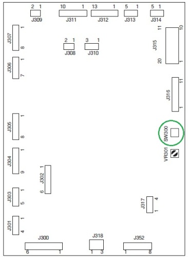
4. На дисплее отобразится «С0».
5. С помощью цифровой клавиатуры на панели управления введите номер нужного сервисного режима.
6. Нажмите кнопку SORT/GROUP.
7. Для выхода из сервисного режима нажмите кнопку сервисного переключателя (SW300).
Сервисные команды:
С0 — Auto exposure sensor monitoring (автоматическая экспозиция датчиков мониторинга)
С1 — Auto exposure adjusting (автоматическая регулировка экспозиции)
С2 — Register A-side adjusting (настройки на А-стороне)
С3 — Blank A-side adjusting
С4 — Curve adjusting (настройка кривых)
С5 — Register B-side adjusting (настройка на B-стороне)
С6 — Blank B-side adjusting
С7 — Lens focus 50% adjusting (регулировка фокусировки на объективе 50%)
С8 — Lens focus 200% adjusting (регулировка фокусировки на объективе 200%)
С9 — Fuser temperature adjusting (регулировка температуры печки)
С10 — Lens home-position sensor adjusting (регулировка положения датчика объектива)
С11 — Mirror home-position sensor adjusting (регулировка положения датчика зеркала)
С12 — Cassette sensor monitoring (кантроль датчика лотка)
С13 — Nip area cycle starting
С15 — Default auto exposure re/setting (настройка экспозиции по умолчанию)
С16 — Copier configuration monitoring (контроль конфигурации копира)
С17 — Control panel LEDs checking (проверка индикаторов панели управления)
С18 — EEPROM memory initializing (инициализация памяти EEPROM)
С21 — Automatic shut-off setting (автоматическое отключение установок)
С22 — Main switch shut-off check (отключение проверки главного выключателя)
С23 — Universal cassette code setting (универсальная настройка лотка)
С24 — Lamp brightness 50% adjusting (коррекция яркости лампы 50%)
С25 — Lamp brightness 200% adjusting (коррекция яркости лампы 200%)