
Сборник руководств на английском языке по эксплуатации и техническому обслуживанию квадроциклов CFMoto моделей CF500/CF500-A/CF500-5B/CF500-5C/CF625-B/CF625-C.
- Издательство: —
- Год издания: —
- Страниц: —
- Формат: PDF
- Размер: 74,3 Mb
Руководство на английском языке по техническому обслуживанию и ремонту квадроциклов CFMoto моделей CF500 и CF500-A.
- Издательство: Chunfeng Holding Group
- Год издания: 2006
- Страниц: 254
- Формат: PDF
- Размер: 12,8 Mb

Руководство на русском языке по эксплуатации и техническому обслуживанию квадроциклов CFMoto модели CF500-A.
- Издательство: —
- Год издания: —
- Страниц: 206
- Формат: PDF
- Размер: 2,8 Mb
Руководство на русском языке по ремонту квадроциклов CFMoto модели CF500-A.
- Издательство: —
- Год издания: —
- Страниц: 266
- Формат: PDF
- Размер: 15,8 Mb

Руководство на русском языке по эксплуатации и техническому обслуживанию квадроциклов CFMoto моделей CF500-2 и CF500-2A 2008 года выпуска.
- Издательство: —
- Год издания: —
- Страниц: 144
- Формат: PDF
- Размер: 6,9 Mb

Руководство на русском языке по эксплуатации и техническому обслуживанию мотовездехода CFMoto модели CF500-3 с полным приводом.
- Издательство: —
- Год издания: —
- Страниц: 163
- Формат: PDF
- Размер: 2,1 Mb
Руководство на английском языке по техническому обслуживанию и ремонту квадроциклов CFMoto моделей CF500-5B и CF500-5C.
- Издательство: Zhejiang CFMOTO Power Co., Ltd.
- Год издания: 2009
- Страниц: 272
- Формат: PDF
- Размер: 23,2 Mb

Руководство на английском языке по эксплуатации и техническому обслуживанию мотовездеходов CFMoto Terracross моделей CF500-6/CF625-3/CF625-6 с полным приводом.
- Издательство: —
- Год издания: —
- Страниц: 135
- Формат: PDF
- Размер: 16,9 Mb

Руководство на русском языке по эксплуатации и техническому обслуживанию квадроциклов CFMoto модели CF625-X6 EFI.
- Издательство: —
- Год издания: —
- Страниц: 157
- Формат: PDF
- Размер: 43,8 Mb
Руководство на русском языке по эксплуатации и техническому обслуживанию квадроциклов CFMoto модели CF800-2X8 EFI.
- Издательство: —
- Год издания: —
- Страниц: 162
- Формат: PDF
- Размер: 3,4 Mb

Руководство на английском языке по техническому обслуживанию и ремонту квадроциклов CFMoto модели CF800-2 Terralander 800 с полным приводом.
- Издательство: Zhejiang CFMOTO Power Co., Ltd.
- Год издания: 2011
- Страниц: 316
- Формат: PDF
- Размер: 16,5 Mb

Руководство на французском языке по эксплуатации и техническому обслуживанию квадроциклов CFMoto моделей Goes 520 и Goes 520 Max с полным приводом.
- Издательство: —
- Год издания: —
- Страниц: 30
- Формат: PDF
- Размер: 2,7 Mb

Руководство на русском языке по эксплуатации и техническому обслуживанию квадроциклов CFMoto моделей HX500-S и HX500-L 2009 года выпуска.
- Издательство: —
- Год издания: —
- Страниц: 146
- Формат: PDF
- Размер: 3,8 Mb
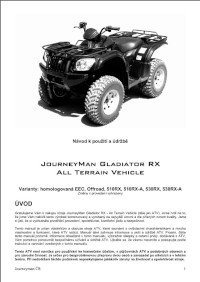
Руководство на чешском языке по эксплуатации и техническому обслуживанию квадроциклов CFMoto модели JourneyMan Gladiator RX.
- Издательство: —
- Год издания: —
- Страниц: 31
- Формат: PDF
- Размер: 1,1 Mb

Руководство на чешском языке по эксплуатации и техническому обслуживанию квадроциклов CFMoto модели JourneyMan Gladiator X-8.
- Издательство: —
- Год издания: —
- Страниц: 24
- Формат: PDF
- Размер: 802 Kb
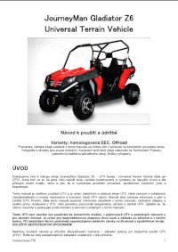
Руководство на чешском языке по эксплуатации и техническому обслуживанию мотовездеходов CFMoto модели JourneyMan Gladiator Z6.
- Издательство: —
- Год издания: —
- Страниц: 24
- Формат: PDF
- Размер: 823 Kb

Руководство на русском языке по эксплуатации и техническому обслуживанию мотовездеходов CFMoto модели SSV 625-Z6 EFI с полным приводом.
- Издательство: —
- Год издания: —
- Страниц: 131
- Формат: PDF
- Размер: 5,7 Mb
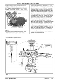
Руководство на русском языке по ремонту карбюратора Mikuni модели BSR36-89.
- Издательство: —
- Год издания: —
- Страниц: 5
- Формат: PDF
- Размер: 393 Kb
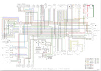
Электросхемы на русском и английсом языках квадроциклов CFMoto моделей CF500/CF500-A/CF500-X5/CF625-X6/CF800-2-X8.
- Издательство: —
- Год издания: —
- Страниц: —
- Формат: PDF
- Размер: 5,1 Mb

![]()
© Обращаем Ваше внимание на то, что вся представленная на сайте информация, касающаяся комплектаций, технических характеристик, изображений, цветовых сочетаний, а также стоимости и наличии, носит информационный характер и ни при каких условиях не является публичной офертой, определяемой положениями Статьи 437 (2) Гражданского кодекса Российской Федерации. Для получения подробной информации о стоимости техники, пожалуйста, обращайтесь в Отдел продаж. Указаны рекомендованные розничные цены в рублях. «Центр Власов» ООО сохраняет за собой право вносить любые изменения в цены, технические характеристики и оснащения комплектаций. 2014 Центр Власов. Продажа квадроциклов в Санкт-Петербурге. Выгодные цены на всю линейку квадроциклов. www.center-vlasov.ru
Заказ обратного звонка
Для езды на мотовездеходе нужно знать его строение, правила вождения, последовательность ремонта и обслуживания. Знание основ поможет в полной мере раскрыть потенциал техники и обеспечит безопасность.
Основные рекомендации находятся в руководствах по эксплуатации квадроциклов CFMOTO который прилогаються в комплекте квадроциклов на русском язике.
Так же Вы можете скачать их ТУТ>>>:
Техобслуживание
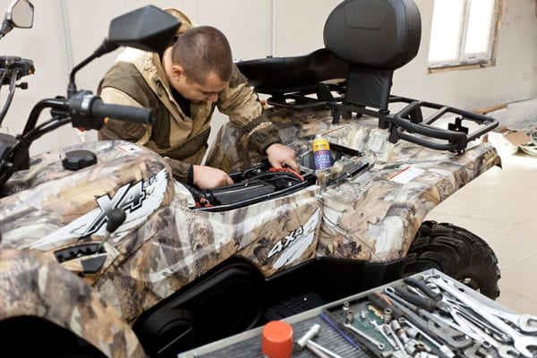
Регулярное техническое обслуживание обеспечит безопасную и продолжительную работу мотовездехода. Контроль, смазку, очистку, регулировку и замену деталей проводят по регламенту или по мере необходимости. Без соответствующих знаний и квалификации эти процедуры лучше проводить в официальных сервисных центрах CFMOTO.
Сначала проверяют уровень и качество масла в двигателе, коробке передач, переднем и заднем редукторе. Затем приступают к другим процедурам:
Замена масляного фильтра;
-Проверка уровня охлаждающей жидкости и её замена;
-Проверка состояния пыльников шрусов;
-Проверка свечей зажигания;
-Чистка воздушного фильтра;
-Снятие и чистка искрогасителя;
-Очистка вариатора;
-Проверка дросселя;
-Регулировка клапанных зазоров впускных и выпускных клапанов;
-Регулировка свободного и общего хода курка газа;
-Проверка передних и задних тормозных колодок;
-Проверка и замена тормозной жидкости;
-Регулировка свободного хода рычага переднего тормоза;
-Регулировка педали тормоза, включателя светового сигнала тормоза;
-Проверка состояния ступичных подшипников;
-Обслуживание стабилизатора поперечной устойчивости;
-Обслуживание аккумуляторной батареи, замена предохранителей;
-Регулировка и замена ламп фар;
-Регулировка преднатяжителя пружин, хода отбоя и сжатия;
-Смазка тросов.
Уход и хранение

Уход за квадроциклом включает:
-Мойку, полировку, чистку;
-Добавление в топливо стабилизатора;
-Смазку внутренних частей двигателя;
-Извлечение и подготовка аккумулятора к хранению;
-Установку заглушек;
-Проверку плотности охлаждающей жидкости;
-Подготовку шкивов вариатора.
-Квадроцикл хранят в сухом прохладном месте, закрывают непрозрачным брезентом или чехлом.
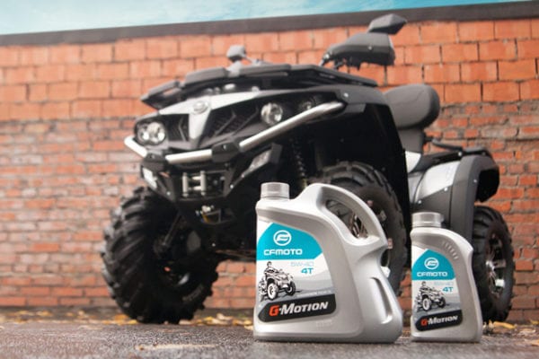
Рекомендованные масла
Правила безопасности
Для двигателя — полусинтетические масла CFMOTO G-MOTION 10W40 4T и 5W40 4T с температурным диапазоном применения от -30 до +40.
Для коробки передач, переднего и заднего редукторов – трансмиссионное масло Gazpromneft 80W-90 GL-5.
Моторные масла G-MOTION специально созданы для максимальной амортизации нагрузок на 4-х тактные двигатели квадроциклов CFMOTO, обладают повышенным запасом защитных свойств, позволяющих обеспечить бесперебойную работу двигателя во всех режимах эксплуатации, включая экстремальные, и увеличить срок службы техники. Масло состоит из качественных базовых компонентов и присадок с оптимальным химическим составом. Их использование гарантирует максимальный срок службы квадроцикла CFMOTO.
Автомобильные масла для мотовездеходов не подходят. Использование ГСМ, не соответствующих рекомендациям производителя, может вывести технику из строя с серьезными последствиями для бюджета.
Правила безопасности
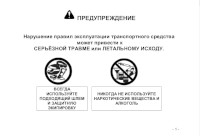
Перед использованием мотовездехода пройдите обучение и инструктаж. Лица моложе 16 лет не допускаются к вождению. Управлять квадроциклом запрещено без защитной экипировки — шлема, защиты глаз, перчаток, ботинок, одежды с длинным рукавом и брюк. Нельзя управлять техникой в состоянии опьянения.
Перед использованием мотовездехода проверяйте его на исправность. Руки всегда должны находиться на руле, а ноги – на подножках. Не двигайтесь на квадроцикле слишком быстро — скорость должна соответствовать рельефу местности, видимости и опыту вождения.
Не передвигайтесь по льду замёрзшего водоёма. Не преодолевайте водные препятствия, глубина которых выше уровня подножек квадроцикла — это может вывести технику из строя. Перевозите пассажиров на креслах и никогда — на багажнике.
Соблюдайте особую осторожность при движении по незнакомой местности. Также будьте предельно внимательными при движении задним ходом, пробуксовке, преодолении препятствий.
Подбирайте только предназначенные для вашей модели шины и поддерживайте рекомендуемое давление. Тюнингуйте мотовездеход только фирменными аксессуарами.
В случае возникновения серьёзных неисправностей рекомендуем обратиться в наш официальный сервисный центр CFMOTO по адресу г.Москва, Сколковское ш.31 стр 31
- Manuals
- Brands
- CF MOTO Manuals
- Offroad Vehicle
- CFORCE 1000 2018
- Service manual
-
Contents
-
Table of Contents
-
Troubleshooting
-
Bookmarks
Quick Links
SERVICE
MANUAL
CFORCE 1000
CF1000AU
CF1000ATR
Related Manuals for CF MOTO CFORCE 1000 2018
Summary of Contents for CF MOTO CFORCE 1000 2018
-
Page 1
CFMOTO SERVICE MANUAL CFORCE 1000 CF1000AU CF1000ATR… -
Page 2
CFMOTO Edition No.:20180817 Edition item: CF1000AU(9AY0-WX-01-1)SM-20180817 Website:www.cfmoto.com… -
Page 3
CFMOTO FOREWORD Maintenance Information T h i s m a n u a l i n t r o d u c e s C F 1 0 0 0 A U , Body Covering Parts CF1000ATR maintenance information, Inspection and Adjustment removal &… -
Page 4
CFMOTO Unit Conversion Table Item Unit conversion 1kgf/cm²=98.0665kPa; Pressure 1psi= 6.895kPa = 0.06895bar 1mmHg= 133.322Pa=0.133322kPa 1kgf·m=9.80665N·m Torque 1N·m=8.85(lbf·in) 1N·m=0.7375621(lbf·ft) 1mL=1cm³=1cc Volume 1L=1000cm³ Force 1kgf=9.80665N Length 1in=25.4mm Danger/Warning/Caution Please read below explanations carefully. It explains the meaning of “DANGER/ WARNING/CAUTION”: Danger: The Danger alert and icon indicates a potential hazard that may cause serious injuries or death. -
Page 5
01 Maintenance Information 1 Maintenance Information 1.1 Precautions ………………1-1 1.2 Location of VIN/EIN…………….1-3 1.3 Main Specification …………….1-4 1.4 Specification ………………1-6 1.5 Tighten Torque ……………….1-8 1.6 Lubricant and Sealant …………….1-10 1.7 Cable,Cooling System and Brake System ………1-11 1.7.1 Wiring Diagram…………….1-11 1.7.2 Brake System Diagram …………..1-14 1.7.2.1 Brake System (Left-hand park) ……….1-14… -
Page 6
CFMOTO 9.Replace aged rubber parts when assembling. Do not splash gasoline, grease onto the surface, as this could cause damage. 10. Apply or inject recommended lubricant into the specified lubrication points. 11. Use the correct special tools for removal and installation. 12. -
Page 7
01 Maintenance Information Engine Break-in There are many movable components inside the engine, such as the piston, piston rings, cylinder, crankshaft, gears, ect. During initial use period, proper run-in for every critical component is necessary. Break-in can help engine components match to each other and adjust to working conditions. -
Page 8
CFMOTO 1.3 Main Specification Item Specification Model CF1000AU CF1000ATR Size length×width×height 2310 mm×1250 mm×1420 mm Wheelbase 1480mm Engine model 2V91Y Displacement 962.6mL Fuel type Minimum 89 or higher octane unleaded gasoline Dry weight 447kg 490kg Passengers 2(Include driver) Max load allowed 210 kg Front wheel 27×9.00-12 51K;27×9.00R14 60L;… -
Page 9
01 Maintenance Information Item Specification Air filter Foam, paper filter Type 0JY0-173000-10000/0JY0-173000-20000 Throttle body Valve diameter 54mm Tank capacity Clutch type Dry and auto centrifugal Transmission type CVT+ Gearshift Gear shift High, low, reverse and parking Gear order Manual/H-L-N-R-P (CVT)ratio 0.7~2.88 “H”gear “L”gear… -
Page 10
CFMOTO 1.4 Specification ● Lubrication Item Standard Service limit Oil capacity Replace oil with filter 2500mL Total dry 2600mL Gear oil capacity Total capacity 600mL Recommend engine oil SAE15W-40 oil for 4-stroke engine. Select alternative according to the 20W-50 following specifications.: 15W-40,15W-50 API level:SG or higher;… -
Page 11
01 Maintenance Information ●Wheel (Front and Rear) Item Standard Service limit Axial 0.8mm 2.0mm Wheel Jump Radial 0.8mm 2.0mm Groove deepness 3.0mm Tire Pressure 45kPa(0.45kgf/cm2) ●Brake Item Standard Service limit Front brake Brake disc thickness 5.0mm 4.0mm Brake pedal freeplay 95 mm ~105 mm Rear brake Brake disc thickness… -
Page 12
CFMOTO ●Light/Dashboard/Switch Item Standard Main Fuse Secondary 40A×1(EPS) 15A×3 10A×2 Headlight 12V ,12W/14W LED Brake light/Tail light 12V, 4.8W 12LED Front turning light 12V, 1.2W 7LED Light and bulb Rear turning light Indicators Rear license light 12V, W5W (BULB) ●Valve mechanism and cylinder head(See 05-Engine) ●Cylinder+Piston+Piston ring+Crank Connecting-rod(See 05-Engine) ●Clutch and transmission (See 05-Engine) 1.5 Tighten torque… -
Page 13
01 Maintenance Information Tightening Torque List Fasteners not included in below table should also be torqued to specification. NOTE: Threads and contact area should be coated with engine oil. Item Type Qty Torque(N•m) Front left mounting bolt, engine GB5789 M10×1.25×130 40~50 Front right mounting bolt, engine GB5789 M10×1.25×100… -
Page 14
CFMOTO ●Special torque for engine(See 05-Engine) ●Follow the specifications below to tighten up normal parts Type Torque N•m Type Torque N•m 5mm bolt, nut 5mm screw 6mm bolt, nut 6mm screw 8mm bolt, nut 20~30 6mmSH flange bolt 10mm bolt, nut 30~40 6mm flange bolt and nut 12mm bolt, nut… -
Page 15
01 Maintenance Information 1.7 Cable, Brake System and Cooling System 1.7.1 Wiring Identification 16 15 driving direction 011101 1 RH headlight connector 7 Connector,brake switch 13 Starter relay 2 EPS fuse 8 LH handlebar A,B 14 LH headlight connector 3 Fuse box 9 Dashboard connector A,B,C 15 USB output socket Daytime running light control 4 EPS connector… -
Page 16
CFMOTO 011201 1 Rectifier 4 Coolant Temperature sensor 2 Ignition Coil 5 CPS 3 Starter Motor Note: Remove the body covering parts before inspection. Removal procedures refer to Chapter 2. 011202 1 Idle Stepping Motor 2 TPS 3 Injector Note:Remove the seat assembly before inspection of those part. Removal procedures refer to Chapter 2. -
Page 17
01 Maintenance Information Speed Sensor Connector Gear Sensor Connector(EU 167) Seat Pressure Sensor Connector Fuel Pump Connector Note:Remove the right panel before working on the parts mentioned above. Removal procedures refer to Chapter 2. 011301 Driving direction 011302 1 Connector, Right Turn 3 License Light Connector 2 Connector, Left Turn 4 Tailer Power Connector Note: Remove the body covering parts before inspection. -
Page 18
CFMOTO 1.7.2 Brake System Parts Diagram 1.7.2.1 Brake System (Left-hand park) 011401 Name Name Parking brake lever 12 Front Brake Hose, LH Fluid Reservoir Assy 13 Front Brake Caliper, LH Fluid Reservoir Hose 2 14 Front Brake Pad Fluid Reservoir Hose 1 15 Hydraulic Induction Switch Master Cylinder Assy 16 Front Brake Caliper, RH… -
Page 19
01 Maintenance Information 1.7.2.2 Brake System (EU 167 Left-hand park) 011501 Name Name Parking brake lever 12 Front Brake Hose, LH Fluid Reservoir Assy 13 Front Brake Caliper, LH Fluid Reservoir Hose 2 14 Front Brake Pad Fluid Reservoir Hose 1 15 Hydraulic Induction Switch Master Cylinder Assy 16 Front Brake Caliper, RH… -
Page 20
CFMOTO 1.7.2.3 Brake System (Right-hand park) 011601 Name Parking Lever Assy Parking Brake Cable Rear View Mirror Seat Assy Remark: Others please refer to chart 011401(Exclude 21 and 22) 011602 1 Front Brake Fluid Hose 3 Master Cylinder Assy 2 Shifting Locking Cable 4 Rear Brake Fluid Hose Note: Remove the body covering parts before inspection. -
Page 21
01 Maintenance Information 1.7.3 Cooling System Parts Diagram 011701 1 Radiator Assy 4 Coolant Inlet Hose 7 Exhaust Pipe I, Idle 2 Coolant Filler/Connecting Pipe 5 Flow Hose, Reservoir 8 Coolant Reservoir Assy 3 Coolant Outlet Hose 6 Hose, Coolant Reservoir Note: Remove the body covering parts before inspection. -
Page 22
02 Body Covering Parts 2.1 Maintenance Information ..2-2 2.5.2 Front Licence Plate…2-13 2.2 Tighten Torque……2-2 2.5.3 Front Bumper Block..2-13 2.3 Seat Assy, Air Filter Cover Assy, 2.5.4 Front Bumper….2-14 Shifting Cover, 2.5.5 Front Deco Cover, LH/RH.2-14 Gearshift Deco Cover Seat heat Insulator, Rear Seat 2.5.6 Headlight Cover, LH/RH. -
Page 23
CFMOTO 2.1 Maintenance Information Pre-cautions This chapter mainly introduces the body covering parts removal and installation procedures. Also the rack, seat, backrest removal and installation instructions. Follow the drawings to arrange the cables, pipes and wirings to the correct position. 2.2 Tighten Torque: M8 bolt 20 (2.0) Torque N·m(kgf·m) M6 bolt 10 (1.0) Torque N·m(kgf·m) -
Page 24
02 Body Covering Parts 2.3 Seat Assy, Air Filter Cover Assy, Shifting Cover, Side Cover, Seat heat Insulator, Rear Seat Bracket 2.3.1 Rear Seat Removal Lift the hook (1). Lift up the rear part and pull out seat (2). Installation Reverse the removal procedures for installation. -
Page 25
CFMOTO 2.3.4 Air Filter Cover, LH Removal Remove the air filter cover (See 2.3.3). Remove three self-tapping scews (1). Remove plastic clip (2). Remove the air filter left cover (3). Installation Reverse the removal procedures for installation. 020401 2.3.5 Air Filter Cover, RH Removal Remove air filter cover (See 2.3.3). -
Page 26
02 Body Covering Parts 2.3.7 Gearshift Deco Cover (Normal 2.3.7.1 Gearshift Deco Cover status ) Removal Remove air filter cover sassy(See 2.3.3). Loosen rubber sleeve (1). Loosen locking point (2). Loosen a plastic clip to the rear (3). Remove the gear shifting deco cover (4). Installation 020501 Reverse the removal procedures for… -
Page 27
CFMOTO 2.3.9 Side Cover, RH Removal Remove the air filter cover (See 2.3.3). Loosen four rubber sleeves (1). Loosen three plastic clips (2). Remove right side cover (3). Installation Reverse the removal procedures for installation. 020601 2.3.10 Seat Heat Insulator Removal Remove left side cover (See 2.3.8). -
Page 28
02 Body Covering Parts 2.4 Front/Rear Rack Cover, Front/ Rear Rack, Handlebar Cover, Hand Guard, Dashboard Cover 2.4.1 Front Rack Cover Center cover Removal Pull the rubber band (1) up. Lift up the center cover. Remove the center cover (2). Installation Reverse the removal procedures for installation. -
Page 29
CFMOTO 2.4.3 Rear Rack Cover Removal 020801 Remove nine M6 bolts (1). Lift up to remove rear rack cover (2). Installation Reverse the removal procedures for installation. 2.4.4 Rear Rack Removal 020802 Remove the bracket cover (See 2.4.3). Remove four M8 bolts (1). Remove two M6 bolts (2) from fender (One piece on each side — See 020901). -
Page 30
02 Body Covering Parts 020901 2.4.5 Handlebar Cover Removal Pull it up Loose two plastic clips (1). Remove the handle bar cover (2). Installation Reverse the removal procedures for installation. 2.4.6 Hand Guard, LH/RH Hand Guard, RH 020902 Removal Remove one M6 bolts (1). Remove one M8 bolts (2). -
Page 31
CFMOTO Hand Guard, RH Removal Remove two M5 bolts (3) (See picture 020903). Remove right hand guard (4) (See pic 020903). Remove right hand guard rod (5). Installation Reverse the removal procedures for installation. Hand Guard, LH Removal / installation See right guard instructions. -
Page 32
02 Body Covering Parts 2.4.8 Dashboard Cover, RH Removal Remove the dashboard cover (See 2.4.7). 021101 Disconnect the ignition switch Remove two screws (1) from dashboard cover. Remove the ignition switch (2). Loose three plastic clips (3). Remove right dashboard cover (4). Installation Reverse the removal procedures for installation. -
Page 33
CFMOTO 2.4.10 Dashboard Lower Cover Removal Remove dashboard right cover (See 2.4.8). Remove dashboard left cover (See 2.4.9). Remove eight screws (1) (See picture 021201,021202) Loose two M6 nuts (2) on the back (See pic 021202). Remove dashboard lower cover (3). Installation Reverse the removal procedures for installation. -
Page 34
02 Body Covering Parts 2.5 Front Lower Panel, Front License Plate, Front Bumper Block, Front Bumper, Front Deco Cover, Headlight Cover, Front Deco Plate, Front Ventilate Cover, Headlight Cover 2.5.1 Front Lower Panel Removal Remove four M6 bolt (1). Remove front lower panel (2). Installation Reverse the removal procedures for installation. -
Page 35
CFMOTO 2.5.4 Bumper Assy Removal Remove front licence plate (See 2.5.1). Remove two M8 bolt (1). Remove the bumper (2). Installation Reverse the removal procedures for installation. Front Bumper Cover, LH(EU) Removal 021401 Remove one M6 bolt (1). Remove front bumper left cover (2). Remove the reflector (3). -
Page 36
02 Body Covering Parts 2.5.6 Headlight Cover, RH Removal Remove front right deco cover (See 2.5.5). Remove four screws (1). Remove two screws (2). Remove M6 bolt (3). Remove headlight right cover (4). Installation Reverse the removal procedures for installation. Headlight Cover, LH Removal/installation See right headlight cover instructions. -
Page 37
CFMOTO 2.5.9 Headlight Cover Removal Remove front deco plate (See 2.5.5). Remove headlight guard (See 2.5.6). Remove front deco plate(See 2.5.7). Remove front vent cover (See 2.5.8). Loose two rubber sleeve (1). Remove the relay box (2). Remove four screws (3) (Two on each side — See picture 021602). -
Page 38
02 Body Covering Parts 2.6 Front Flare Fender LH/RH, Front Upper Inner fender LH/RH, Front Fender, Engine Left Deco Cover, Rear Flare Fender LH/RH, Footrest LH/RH, Rear License Plate, Rear Cargo Box Cover, Rear Plate, Rear Cargo Box and Bracket, Tailight Cover LH/RH, Rear Fender 2.6.1 Front Flare Fender, RH Removal… -
Page 39
CFMOTO 2.6.3 Front Fender Removal R e m o v e s i d e c o v e r , L H / R H ( S e e 2.3.8,2.3.9). Remove front rack (See 2.4.2). Remove the dashboard cover (See 2.4.7). Remove the headlight panel (See 2.5.9). -
Page 40
02 Body Covering Parts 2.6.4 Engine Side Cover, LH Removal Loosen three rubber sleeves (1). Loosen two plastic clips (2). Remove the engine side cover (3). Installation Reverse the removal procedures for installation. 021901 Side Cover Bracket Removal Remove three M6 bolt (1). Remove side cover bracket (2). -
Page 41
CFMOTO 2.6.6 Footrest, RH Removal Remove front fender (See 2.6.3). Remove side cover, LH/RH (See 2.3.8,2.3.9). Remove rear fender (See 2.6.13). Remove five M6 bolts (1). Remove four M6 bolts (2). Remove anti-sliding claws (3). Remove right footrest (4). Installation Reverse the removal procedures for installation. -
Page 42
02 Body Covering Parts 2.6.9 Tool Box Locker Removal Open the tool box cover (1). Loosen two plastic clips, two on each side Remove the tool box locker (3). Installation Reverse the removal procedures for installation. 022101 2.6.10 Rear Plate Removal Remove rear seat (See 2.3.1). -
Page 43
CFMOTO 2.6.12 Taillight Cover, RH Removal Open the rear case cover (1). Loosen three screws (2). Loosen one M6 bolt (3). Loosen two plastic clips (4) at the bottom. Disconnect taillight connector (5) (See picture 022203). Remove right taillight cover (6). Installation Reverse the removal procedures for installation. -
Page 44
02 Body Covering Parts 2.6.13 Rear Fender Removal Remove side cover, LH/RH (See 2.3.8, 2.3.9). Remove flare fender, LH/RH (See 2.6.5). Remove tool box cover locker bracket (See 2.6.11). Remove taillight plate, LH/RH (See 2.6.12). Remove two M6 bolt (1). Remove four M6 bolt (2). -
Page 45
CFMOTO 2.7 Front/ Mid/ Rear Lower Panel, Front Suspension Panel LH/RH, Rear Suspension Panel LH/ RH, Reservoir Bracket, Pipe Plug 2.7.1 Front Lower Plate Removal Remove five M6 bolts (1). Remove front lower panel (2). Installation Reverse the removal procedures for installation. -
Page 46
02 Body Covering Parts 2.7.4 Front Suspension Cover, RH Removal Remove two M6 bolts (1). Remove front right suspension cover (2). Installation Reverse the removal procedures for installation. Front Suspension Cover, LH Removal/ installation See right suspension cover instructions. 022501 2.7.5 Rear Suspension Cover, LH Removal Remove one M6 bolt (1). -
Page 47
CFMOTO 2.8 Seat Belt(EU 167) Removal Remove two bolts Remove seat belt assy Installation Reverse the removal procedures for installation. 022601 02-26… -
Page 48
03 Periodic Inspection and Adjustment 3 Periodic Inspection and Adjustment Maintenance Information …3-1 3.6 Shifting Mechanism ….3-11 3.1 Maintenance Period ….3-2 3.7 Fuel System ……3-11 3.2 Maintenance Method ….3-3 3.8 Throttle Inspection ….3-12 3 . 3 S t e e r i n g C o l u m n & B r a k e 3.9 Cooling System….3-13 System …….. -
Page 49
CFMOTO 3.1 Maintenance Period Vehicle maintenance is a periodic work. Maintaining the vehicle in the specific periods can keep the engine in good performance, reliable running. Note: This chart is designed for normal operation. For severe operating conditions, maintenance should be performed more frequently. A:Adjust C:Clean Every… -
Page 50
03 Periodic Inspection and Adjustment 3.2 Maintenance Method Working Item Period Half Service standard Part Inspection Item Normal year year Handle bar Handle smoothly ○ Steering Damage ○ Steering column Steering system condition ○ system Ball pin movement ○ Brake Clearance ○… -
Page 51
CFMOTO Item Period Half Standard Part Inspection Item Daily Yearly year Output Connector loose ○ ○ Drive shaft(Drive system Spline movement ○ shaft) Spark clearance: Ignition Sparkplug ○ 0.8mm~0.9mm system Ignition ○ Electrical Connectors equipment Battery ○ condition Connecting loose Wiring ○… -
Page 52
03 Periodic Inspection and Adjustment 3.3 Steering Column and Brake System Stop the vehicle on a flat ground. Move the handlebar and move up and down to see handlebar’s movement. If no movement found, inspect and maintain as necessary. If the steering column has movement, tighten the fasteners or disassemble the steering column for maintenance. -
Page 53
CFMOTO Front Brake Fluid Level Upper line Inspect the fluid level. When the brake fluid level is lower than (1) (LOWER) line, inspect the master cylinder, brake hose and other for leakage.(See picture 030601) Loosen two screws (2) to remove the fluid cap. -
Page 54
03 Periodic Inspection and Adjustment Rear Brake Fluid Level Inspect brake fluid level. W h e n b r a k e f l u i d l e v e l i s b e l o w t h e «LOWER»… -
Page 55
CFMOTO 3.4 Front Wheel Position the vehicle on a level ground. Elevate the appropriate side of the vehicle by placing a stands or other suitable tool under the footrest frame. Shake the wheel to check for free play or looseness. If any freeplay or looseness is found, inspect A-arms, axle, rim bolts and nuts and tighten them if necessary. -
Page 56
03 Periodic Inspection and Adjustment Tire Pressure Use tire pressure gauge to measure tire pressure. CAUTION: Test tire pressure when the tire is cold. Maintain proper tire pressure. Improper inflation may affect ATV maneuverability, tire gauge comfort, or uneven wear to tires. 030901 Tire and tire pressure Front wheel… -
Page 57
CFMOTO Wheel Nut and Axle Inspect the front wheel axle, rear wheel axle nut (1) and pin for looseness. If any looseness inspected Tighted up to the specific torque. Torque: Front axle nut: 220N·m~250N·m (22kgf·m~25kgf·m) Rear axle nut: 220N·m~250N·m (22kgf·m~25kgf·m) 031001 3.5 Suspension System Set the vehicle on a flat ground. -
Page 58
03 Periodic Inspection and Adjustment 3.6 Shifting Mechanism Shifting mechanism (See picture 031101) Shift the vehicle to inspect if the shifting mechanism can work smoothly and the gear is meshed. If shifting is not smooth, lubricate the pivots. If necessary, adjust shifting rod (2) length. Loosen the nut (3) to adjust it. -
Page 59
CFMOTO 3.8 Throttle Inspection Inspect throttle lever (1) for free play. (See picture 031201) Free play: 3mm~5mm(See picture 031202) 031201 Adjust throttle lever if free play is out of specification. Slide sleeve (2) out of place. loosen throttle cable locking nut (3). 031202 Turn adjuster to change the throttle lever free play. -
Page 60
03 Periodic Inspection and Adjustment 3.9 Cooling System CAUTION: UPPER For safety when checking the coolant level in the reservoir tank, never open the pressure cap when the engine is hot (more than 100 C). Escaping steam and fluid can cause severe burns. -
Page 61
CFMOTO If the coolant level is below the mark Reservior «LOWER» (1), remove the reservoir tank cap and add coolant to the mark «UPPER» (2). (See picture 031401) Recommended Coolant: Any commercially available coolant that is safe for aluminum. Standard Mixture Ratio: 50% Coolant — 50% Water (The freezing temperature varies according to the mixture ratio. -
Page 62
03 Periodic Inspection and Adjustment Coolant Gauge Inspection The indicator (1) should indicate 0-1 bar when the engine is cold. Start the engine to check coolant gauge for response. If the indicator doesn’t move when the engine is warm, determine the cause and repair. (See picture 031501) O O O O P P P P C C C C 031501 3.10 Lighting… -
Page 63
CFMOTO 3.11 Selective Shock Absorber View Damping Force Knob for Compression Damping Force Knob for Compression Spring adjust Spring adjust D a m p i n g D a m p i n g Force Knob Force Knob for Restoring for Restoring 031601 03-16… -
Page 64
03 Periodic Inspection and Adjustment Front Shock Absorber Adjustment A c c o r d i n g t o l o a d d e v i a t i o n , a d j u s t damping force knob for compression (1) and damping force knob for restoration (2). -
Page 65
CFMOTO 3.12 Shock Absorber Selection Front/Rear Shock Absorber Shape Selection Adjusting retainer Adjusting retainer 031801 Rear shock absorber Front shock absorber 03-18… -
Page 66
03 Periodic Inspection and Adjustment Front shock absorber spring preload adjustment Use shock absorber adjusting tool. Adjusting the preload position (1) depends on the vehicle load. Turn it clockwise to increase the spring preload. (See picture 031701) 031901 Rear shock absorber spring preload adjustment Use shock absorber adjusting tool. -
Page 67
04 Alongside Engine 4 Alongside Engine 4.3 Exhaust System…….4-5 Maintenance Information….4-1 4.4 Cooling System……4-6 4.1 Fuel System……4-2 4.5 Engine Removal and Installation 4.2 Intake System……4-3 ……….4-7 Maintenance Information Precautions ·Make sure the vehicle engine is off for more than 1 hour to avoid protential injuries. ·Do not damage the frame, engine body, bolts, or cables. -
Page 68
CFMOTO 4.1 Fuel System Canister Removal (US) Remove body covering parts. (Refer to Chapter 2 Body Covering Parts) Remove the clamp A10(1) Remove fuel vapor hose II (2). 040201 Remove the clamp A10 (1). Remove fuel vapor hose I (2). 040202 Remove nuts (1). -
Page 69
04 Alongside Engine 040301 4.1 Fuel System Removal Remove body covering parts (See 02 body covering parts). Remove four M6 bolt (1). Remove fuel pump connector (2). Disconnect fuel pump quick joint (3). Remove the tank (4). Remove quick joint (5). Remove the whole fuel pipe assembly (6). -
Page 70
CFMOTO CAUTION Gasoline is highly flammable. Smoke and fire is forbidden in the work place. Also be highly careful with electric spark. Gasoline vapor has a risk of explosion. Please work in a well ventilated area. Installation Reverse the removal procedures for installation. All the connectors should in right position. -
Page 71
04 Alongside Engine Remove three M6 bolt (4) 040501 Remove clamp (5) Remove exhaust pipe (6). Remove clamp (7). Remove air filter (8). NOTE The air filter foam element should be washed and the main air filter replaced if it is dirty. -
Page 72
CFMOTO 4.3 Exhaust System Removal Remove the rear seat (1). Remove the front seat (2). Remove right side cover (3) (See 02 body covering part). 040601 Remove four M6 bolt (1). Turn up the seat insulator (2) to the left. 040602 Remove four M6 bolt (1). -
Page 73
04 Alongside Engine Remove oxygen sensor (1). Remove two M8 muffler connector nut (2). Remove two M8 bolt. Remove two-into-one exhaust pipe (Keep the exhaust washer on cylinder head stored). 040701 Oxygen sensor (1). Remove two M8 muffler connector nut (2). Remove front cylinder exhaust pipe (3) (Keep the exhaust washer on cylinder head stored). -
Page 74
CFMOTO 4.5 Engine Removal and Installation Remove body covering part (See 02 body covering part). Remove fuel system (See 4.1). Remove intake system (See 4.2). Remove exhaust system (See 4.3). Remove cooling system (See 4.4). Disconnect electrical connector. Remove throttle cable. Remove throttle valve (1). -
Page 75
04 Alongside Engine Remove inlet pipe filer cover (1). 040904 Remove screw clamp (1). Disconnect inlet connector (2) from the engine. Loose the screw clamp (3). 040901 Disconnect outlet connector (4) from the engine. Remove front drive shaft. Remove rear drive shaft. Remove one M10×1.25×100 bolt (1). -
Page 76
5.1 Engine Maintenance Information 05 Contents 5.1 Maintenance Information………………………………………..5-2 5.2 Intake Pipe, Cylinder Head and Cylinder Body …………..….…5-20 5.3 Case, Crankshaft and Gear Transmission …………..5-67 5.4 CVT………………………………………………………………..………5-110 5.5 Engine Lubrication System … ….……………………………..………5-128 5.6 Engine Starting System………………………………………..………5-145 5.7 Intake System…………………………………………………..………5-157 5.8 Cooling System………………………………………………..………5-163 5.9 Electrical System……………………………………………..….………5-188 5.10 Troubleshooting …………………………………………..……………5-219… -
Page 77
CFMOTO 5.1 Maintenance Information Unit Form ………………..5-3 5.1.1 Pre-cautions ………………5-4 5.1.2 Fuel, Engine Oil, Gear Oil and Engine Coolant……5-5 5.1.3 Engine Break-in…………….5-5 5.1.4 EIN Location…………….. 5-6 5.1.5 Engine Specification…………..5-7 5.1.6 Service Limits …………….5-8 5.1.7 Engine Tightening Torque Form …………5-13 5.1.8 Engine Service Tool …………..5-15 5.1.9 Engine Service Materials……………5-18 5.1.10 Engine Service Schedule …………5-19… -
Page 78
5.1 Engine Maintenance Information Unit Form Item Unit calculation 1kgf/cm =98.0665kPa Pressure 1psi=6.895kPa=0.06895bar 1mmHg=133.322Pa=0.133322kPa 1kgf·m=9.80665N·m Torque 1N·m= 8.85(lbf·in) 1N·m= 0.7375621(lbf·ft) 1mL=1cm =1cc Volume 1L=1000cm Force 1kgf=9.80665N 1in=25.4mm Danger/Caution/Note Please read below instruction carefully. DANGER: The Danger alert and icon indicates a potential hazard that may result in death or serious injury. -
Page 79
CFMOTO 5.1.1 Precautions WARNING: Working on the engine in the right way is important for technicians safety and engine reliability. ·Make sure the exhaust gas can be vented out if starting the engine indoor. ·Use extreme caution when working with poisonous or high-flammable material. And make sure the working place is well ventilated. -
Page 80
5.1 Engine Maintenance Information 5.1.2 Fuel, Engine Oil, Gear Oil and Coolant Fuel: Use RQ-92# gasoline or higher 20W-50 Oil: SAE15W-40, SG or higher level in API. 15W-40,15W-50 If SAE15W-40 engine oil is not available, follow the chart on the right to choose 10W-40,10W-50 one oil according to the enviornment 10W-30… -
Page 81
CFMOTO 5.1.4 EIN Location Engine left side 050601 EIN Location 050602 Engine right side 05-6… -
Page 82
5.1 Engine Maintenance Information 5.1.5 Engine Specification Item Specification Style V-twin, water cooled, 4-stroke,8 valves, SOHC Bore×Stroke 91mm×74mm Displacement 962.6mL Compress ratio 10.6:1 Idle speed 1300r/min±130r/min Starting method Electrical start Ignition style/angle ECU/BTDC8° 1300r/min Electrical Sparkplug/spark DCPR8E(NGK)/0.8mm~0.9mm system clearance Magneto AC 3-phase.350W/5000r/min;… -
Page 83
CFMOTO 5.1.6 Service Data Lubrication system Item Standard Service limit Replace oil with filter 2500mL( Crankcase ) Oil Capacity Total dry 2600mL( Crankcase ) Gear oil Total capacity 600mL (Gearcase ) SAE15W-40, SG or higher level in API. If 20W-50 SAE15W-40 engine 15W-40,15W-50 oil is not available,… -
Page 84
5.1 Engine Maintenance Information Induction system Item Standard Throttle body 0JY0-173000-10000/0JY0-173000-20000 Intake pressure and thermo sensor 0JY0-175000 Injector 0JYA-171000 Idle speed 1300r/min±130r/min Electrical system Item Standard Remark Type DCPR8E(NGK) Spark plug Clearance 0.8mm~0.9mm Spark size >8mm,101kPa First level 0.7Ω~0.75Ω Ignition coil resistance Secondary level 6.0kΩ~7.0kΩ… -
Page 85
CFMOTO Valve mechanism and cylinder head Item Standard — mm Limit Remark Intake —— Valve diameter Exhaust —— Valve thickness Intake and exhaust Valve clearance(Cold Intake 0.06~0.14 —— engine) Exhaust 0.11~0.19 —— Valve conducting pipe Intake and exhaust 5.000~5.012 5.045 diameter Intake 4.965~4.980… -
Page 86
5.1 Engine Maintenance Information Cylinder, Piston, Piston Ring, Crankshaft and Connecting Rod Item Standard — mm Limit Remark Cylinder compress pressure 1000kPa —— Cylinder body roundness 0.038 0.090 (3 diameter run out) Cylinder roundness (Diameter 0.015 0.020 run out) Cylinder hole diameter 90.99~91.01 ——… -
Page 87
CFMOTO Item Standard — mm Limit Remark Drive belt width 33.7(Fiber level) 32.2 Driven pulley sliding sleeve 38.10~38.14 38.30 diameter Shifting fork and groove 0.20~0.40 0.50 clearance Shifting fork moving 5.80~5.90 5.70 thickness H/L sliding fork groove 6.10~6.20 6.30 width Output main gear sliding 6.10~6.20 6.30… -
Page 88
5.1 Engine Maintenance Information 5.1.7 Engine Tighten Torque Torque Item Qty Type (mm) Remark (N·m) Bolt M14×1.5 M14×1.5 Oil drain bolt M14×1.5 M14×1.5 Screw plug ZM14 Cover with thread locker Drain bolt M12×1.5 M12×1.5 Flange bolt M8×12.5 (Left M8×12.5 crankcase) Screw cap R21/8 Cover with thread locker… -
Page 89
CFMOTO Type Torque Item Remark (mm) (N·m) Bolt M5×16 (Oil pump) M5×16 With thread locker Screw M8×20 (Overriding clutch) M8×20 With thread locker Bolt M6×30 (Magneto stator) M6×30 With thread locker Bolt M6×35 (High power magneto With thread locker M6×35 stator) Cylinder head cover bolt assy Bolt M6×45 (Front cylinder thermostat… -
Page 90
5.1 Engine Maintenance Information 5.1.8 Engine Service Tools Measuring tool Tool name Specification Usage Remark Vernier caliper 0~150mm Measure the length and thickness Measure rocker arm shaft, valve rod, Micrometer 0~25mm camshaft’s diameter. Micrometer 25mm~50mm Measure the max-range of cam Micrometer 75mm~100mm Measure the piston size Cylinder inner dial… -
Page 91
CFMOTO Engine Service Special Tools Tool name Usage 0JWA-000000-871-001 Oil pipe connector measure the oil pressure Bearing 60/28 removing 0800-014001-922-003 Remove bearing 60/28 tool 0800-014001-921-002 Bearing pressing tool Press bearing 0800-041000-922-001 Crankshaft locking screw Lock the crankshaft 0800-031000-922-001 Magneto removing tool Remove magneto rotor 0800-031000-922-003 Rotor locker Lock the crankshaft… -
Page 92
5.1 Engine Maintenance Information Name Use to Front output shaft oil seal For oil seal 35×61×9 0800-060000-923-001 pressor installation Front output shaft bearing Assemble and removal the 0JWA-012000-922-005 retainer wrench bearing retainer 0800-062301-923-001 Front output shaft pressor Install front output shaft Driven bevel gear nut 0800-062206-922-001 Install/remove the locking nut… -
Page 93
CFMOTO 5.1.9 Engine Service Materials Engine service materials include engine oil, gear oil, grease, coolant, flat sealing glue, cylinder locking glue and so on. Name Specification Use position Remark Cylinder inner moving parts. Crankcase, CVT SAE15W-40 case inner moving parts. Capacity API level: SG or higher Cylinder head moving… -
Page 94
5.1 Engine Maintenance Information 5.1.10 Engine Maintenance Schedule NOTE: This schedule is designed for normal use. Under severe use, maintenance the engine and vehicle more frenquently. A:Adjust C:Clean Every Every Every 100h Every 200h 10h or I:Inspect 25h or 50h or or 3000km or 6000km Remark… -
Page 95
CFMOTO 5.2 Intake Pipe, Cylinder Head and Cylinder Body 5.2.1 Service Tool and Material …………..5-21 5.2.2 General Information……………5-26 5.2.3 Maintenance and Inspection…………5-27 5.2.4 Intake Pipe ………………5-31 5.2.5 Cylinder Head Cover…………..5-32 5.2.6 Timing Chain Tensione…………..5-33 5.2.7 Cam Timing Sprocket…………..5-35 5.2.8 Rocker Arm………………5-38 5.2.9 Cylinder Head …………….5-41 5.2.10 Camshaft … -
Page 96
5.2 Intake Pipe, Cylinder Head and Cylinder Body 5.2.1 Service Tool and Material Service Tools Name Page Spark plug socket 0800-022800-922-001 5-28 Camshaft locking tool 0800-024001-922-001 5-29/35/37 Pressure gauge seat 0800-000000-871-002 5-30 Crankshaft locking screw 0800-041000-922-001 5-47 Valve spring compressor CF188-022006-922-001 5-52/53 Piston ring compressor… -
Page 97
CFMOTO Intake Pipe 052201 1 0.5N·m (5 lbf·in) 5 20N·m (5 lbf·ft) 9 Oil 2 6N·m (53 lbf·in) 6 0.5N·m (5 lbf·in) 10 Oil 3 243 thread locker 7 243 thread locker 11 243 thread locker 4 Oil 8 6N·m (53 lbf·in) 12 6N·m (53 lbf·in) 05-22… -
Page 98
5.2 Intake Pipe, Cylinder Head and Cylinder Body Cylinder head(Ι) 052301 1 Oil 9 Oil 17 10N·m(89 lbf·in) 2 12N·m(106 lbf·in) 10 20N·m(15 lbf·ft) 18 30N·m(22 lbf·ft) 3 60N·m(44 lbf·ft) 11 243 thread locker 19 7N·m(62 lbf·in) 4 Oil 12 Oil 20 243 thread locker 5 20N·m(15 lbf·ft) 13 12N·m(106 lbf·in) -
Page 99
CFMOTO 052401 1 10N·m(89 lbf·in) 9 Oil 17 10N·m(89 lbf·in) 2 30N·m(22 lbf·ft) 10 20N·m(15 lbf·ft) 18 20N·m(15 lbf·ft) 3 243 thread locker 11 12N·m(106 lbf·in) 19 243 thread locker 4 Oil 12 Oil 5 Oil 13 12N·m(106 lbf·in) 6 6N·m(53 lbf·in) 14 7N·m(62 lbf·in) 7 5N·m(44 lbf·in) 15 Oil… -
Page 100
5.2 Intake Pipe, Cylinder Head and Cylinder Body Cylinder Body and Piston 052501 1 Oil 2 Oil 3 10N·m (89 lbf·in) 4 5N·m (44 lbf·in) 5 Oil 05-25… -
Page 101
CFMOTO 5.2.2 General General rules should be followed below: In cylinder head/cylinder body exploded view, same part uses the same numbers; different parts or only one part, use different part numbers. The service difference between cylinder 1 and cylinder 2 has special instructions in this manual. -
Page 102
5.2 Intake Pipe, Cylinder Head and Cylinder Body 5.2.3 Maintenance and Inspection Maintenance Valve Clearance Adjustment Note: Inspect and adjust of the valve clearance must be performed on a cold engine. R e m o v e t h e c y l i n d e r h e a d c o v e r. Turn the crankshaft until the cylinder is at TDC. -
Page 103
CFMOTO Remove the radiator cap Warning: Wear suitable protecting equipment when removing the radiator cap to avoid heat burns. Remove parts to access the cylinder head. Remove ignition line. Clean the place around the spark plug, use spark-plug socket (0800-022800-922-001) Remove spark plug from cylinder head. -
Page 104
5.2 Intake Pipe, Cylinder Head and Cylinder Body Warning: Do not scratch or damage the piston or cylinder head surface. Note: The sign on timing sprocket must align with the surface of the cylinder head. (See picture 052901) Use camshaft locking tool (0800-024001- 922-001) to lock the camshaft at TDC. -
Page 105
CFMOTO Leakdown Test Connect to suitable air power, set the pressure gauge to zero. Note: All the air pressure gauge has detailed instructions and pressure range. Set the pressure gauge seat on cleaned spark plug hole (0800-000000-871-002). Inject compressed air into the cylinder. Follow the pressure gauge and record the leaking percentage. -
Page 106
5.2 Intake Pipe, Cylinder Head and Cylinder Body 5.2.4 Intake Pipe Intake pipe removal Unplug the fuel pump power connector. Run the engine until it dies to release the fuel pipe pressure. Warning: Fuel pipe may be under pressure. Use absorbable cloth to cover the pipe connector. -
Page 107
CFMOTO 5.2.5 Cylinder Head Cover Removal Loosen the cylinder head cover mounting bolts. 053201 Cylinderhead cover Cylinderhead mounting bolt cover Remove cylinder head cover and sealing gasket. Cylinder head cover inspection Inspect the cylinder head cover for cracks or hardness. Replace if necessary. Cylinder head assembly Reverse the removal procedures for installation. -
Page 108
5.2 Intake Pipe, Cylinder Head and Cylinder Body 5.2.6 Timing Chain Tensioner Note: Make sure the front cylinder is at TDC position before removal and installation. See Camshaft section. Tensioner Removal Warning: The spring of the timing chain tensioner is loaded. Do not operate it when the engine is working, because the exhaust system is very hot. -
Page 109
CFMOTO Tensioner Installation Reverse the removal performances for installation. However, pay attention to the following items. Note: Before installing chain tensioner, make sure the camshaft timing sprocket can rotate forwards and backwards. Apply some engine oil on push-pull arm before installing tensioner. Note: Insert the straight screwdriver into the groove on the end of the tensioner. -
Page 110
5.2 Intake Pipe, Cylinder Head and Cylinder Body 5.2.7 Camshaft Timing Sprocket Removal the timing sprocket Remove the cylinder head cover. Turn the crankshaft to front cylinder TDC. R e f e r t o c a m s h a f t i n t h i s c h a p t e r. Loosen the timing chain tensioner. -
Page 111
CFMOTO Installation the timing sprocket Reverse the removal procedures for installation. Clean the assembly surfaces and camshaft screw before installation. 053601 1 Camshaft assemble surface 2 Screw M a k e s u r e t h e t i m i n g s p r o c k e t a n d crankshaft is at TDC before assembly. -
Page 112
5.2 Intake Pipe, Cylinder Head and Cylinder Body Install all the removed parts. 053701 1.Camshaft locking tool (P/N:0800-024001-922-001) 2 Camshaft timing sprocket bolt 3 Camshaft timing sprocket 05-37… -
Page 113
CFMOTO 5.2.8 Rocker Arm Remove the rocker arm Remove the cylinder head cover. Remove chain tensioner and camshaft timing sprocket. Remove the bolt (3) and camshaft locking plate (2). 053801 Camshaft 1 Cylinderhead 2 3 Bolt locking plate Remove the rocker arm shaft. Remove the rocker arm assembly (Intake and exhaust), including adjusting screw and nut. -
Page 114
5.2 Intake Pipe, Cylinder Head and Cylinder Body Remove the thrust washers. Wa r n i n g : D o n o t m i s s t h e t h r u s t washers (2) or drop them into timing chain room. -
Page 115
CFMOTO Rocker arm shaft inspection Inspect rocker arm shafts for scratches. Replace shafts as necessary. Measure rocker arm shaft diameter. Rocker arm diameter 11.973mm~11.984mm (0.4714in~0.4718in) Service 11.960mm limit (0.4709in) If reached the service limit, parts must be replaced. 054001 1 Diameter measuring position Install the rocker arms Note: Use the same way to install the intake and exhaust rocker arm. -
Page 116
5.2 Intake Pipe, Cylinder Head and Cylinder Body 5.2.9 Cylinder head Remove the cylinder head The 2 cylinder heads remove in the same manner. Drain out the coolant (See cooling system). Note: Use compressed air to blow out the coolant left before removing the cylinder head. -
Page 117
CFMOTO Cylinder head inspection Inspect timing chain guide for wear, cracks or other damages. Replace if damaged. Check for cracks between valve seats. If any, replace cylinder head. Check mating surface between cylinder and cylinder head for contamination. If any, clean both surfaces. Clean oil supply through the cylinder head of contamination. -
Page 118
5.2 Intake Pipe, Cylinder Head and Cylinder Body First, torque cylinder head screws M10 in a criss-cross sequence to 20N.m (15 ft-lb.), then tighten to 60N.m (44 ft-lb). I n s t a l l c y l i n d e r h e a d s c r e w s M 6 . Check chain guide for movement. -
Page 119
CFMOTO Camshaft Timing Note: If a piston (cylinder 1 or 2) is set to TDC, the camshaft timing gear of the opposite cylinder should appear in the following position. (See picture 054401) 054401 Marks on Timing Gear Cylinder of Opposite Cylinder Head Base Camshaft Timing Cylinder 2 Turn crankshaft until piston is at TDC… -
Page 120
5.2 Intake Pipe, Cylinder Head and Cylinder Body Remove the crankshaft position sensor (2). (See picture 054501) 054501 Crankshaft Position 1 Screw 2 Sensor (CPS) Use an 18mm socket to turn crankshaft until piston 2 (rear) is at TDC. (See picture 054502) 054502 1 18mm Socket… -
Page 121
CFMOTO When the rear piston is at TDC, “2“ mark on magneto flywheel and the magneto cover mark (center of bore) are aligned. 054601 1 Mark “2” on MAG Flywheel 2 CPS Location 3 Notch on MAG Cover At TDC, the printed marks on the camshaft timing gear should be parallel to the cylinder head. -
Page 122
5.2 Intake Pipe, Cylinder Head and Cylinder Body To lock crankshaft at TDC, remove from crankcase plug screw with sealing ring. 054701 Crankcase PTO Plug Sealing Side Screw Ring Lock crankshaft with the crankshaft locking bolt (0800-041000-922-001). Note: Make sure the locking bolt engages in the groove of the crankshaft. -
Page 123
CFMOTO Camshaft Timing Cylinder 1 Turn cylinder 2 to TDC, see Camshaft Timing, Cylinder 2. Note: Do not lock crankshaft. Use a 18mm socket, turn crankshaft 280 counter-clockwise, until “1” mark on magneto flywheel and the magneto cover mark (center of bore) are aligned. 054801 18mm Turn Crankshaft 280… -
Page 124
5.2 Intake Pipe, Cylinder Head and Cylinder Body Note: At TDC, the printed marks on the camshaft timing gear should be parallel to cylinder head. Warning: Crankshaft can not be locked at cylinder 1 TDC. 054901 Marks on Camshaft Cylinder Head Timing Gear Base Camshaft Removal… -
Page 125
CFMOTO Remove rocker arms (see ROCKER ARM). Remove camshaft. Note: For removal, rotate camshaft so that intake/ exhaust lobe shows to upper side of cylinder head. Camshaft Inspection Check each lobe and bearing journal of camshaft for scoring, scuffing, cracks or 055001 other signs of wear. -
Page 126
5.2 Intake Pipe, Cylinder Head and Cylinder Body Measure matching clearance between two ends of camshaft and cylinder head Camshaft bearing hole diameter (Timing chain side) 35.007 mm~35.025 mm (1.3782 in~1.3789 in) Service 35.040 mm(1.3795 in) limit Camshaft bearing hole diameter (Spark plug side) 22.012 mm~22.025 mm (0.8666 in~0.8671 in) -
Page 127
CFMOTO 5.2.11 Valve Spring Valve Spring Removal Remove rocker arm(see ROCKER ARM a b o v e ) . R e m o v e c y l i n d e r h e a d ( s e e CYLINDER HEAD above). -
Page 128
5.2 Intake Pipe, Cylinder Head and Cylinder Body Remove valve cotters. Withdraw valve spring compressor, valve spring retainer and valve spring. 055301 Valve Spring Compressor Clamp (P/N: CF188-022006-922-001) 2 Valve Spring Compressor Cup 3 Valve Cotter Valve Spring Inspection C h e c k v a l v e s p r i n g f o r v i s i b l e damages, If any, replace valve spring. -
Page 129
CFMOTO 5.2.12 Valve Valve Removal R e m o v e v a l v e s p r i n g ( s e e VA LV E SPRING). Push valve stem, then pull valves (intake and exhaust) out of valve guide. -
Page 130
5.2 Intake Pipe, Cylinder Head and Cylinder Body Valve Inspection Valve Stem Seal Always install new seals whenever valves are removed. Valve Inspect valve surface, check for abnormal s t e m w e a r a n d b e n d i n g . I f o u t o f specification, replace with a new one. -
Page 131
CFMOTO Valve Bevel and Valve Seat Check valve face and seat for burning or pitting Replace valve or cylinder head if there are signs of damage. Ensure seating of valves properly. Apply some lapping compound to valve face and work valve on its seat with a lapping tool (see Valve Installation Procedure below). -
Page 132
5.2 Intake Pipe, Cylinder Head and Cylinder Body 5.2.13 Cylinder Cylinder Removal Remove chain tensioner (see CHAIN TENSIONER). Remove the camshaft timing gear (see CAMSHAFT TIMING GEAR). Remove cylinder head (see CYLINDER HEAD). Pull cylinder. Discard cylinder base gaskets. 055701 Camshaft Timing Cylinder Base Chain… -
Page 133
CFMOTO Cylinder out of Round Measure cylinder diameter in piston axis direction from top of cylinder. Take another measurement from the angle of 90° and compare with the first one. (See picture 055801) Note: Take the same measuring points described in Cylinder Taper. Cylinder out of round (Diameter run out) 055801 0.015 mm(0.0006 in) -
Page 134
5.2 Intake Pipe, Cylinder Head and Cylinder Body 055901 Piston Ring Compressor 1 Cylinder 2 Piston 3 Tool (P/N:0800- 040003-922-001) 5.2.14 Piston Piston Removal Remove cylinder head (see CYLINDER HEAD) Remove cylinder (see CYLINDER). Place a rag under piston in the area of the timing chain compartment to avoid dropping circlips inside the crankcase. -
Page 135
CFMOTO Piston Inspection Inspect piston for scoring, cracking or other damages. Replace piston and piston rings if necessary. M e a s u r e p i s t o n a t 8 m m ( 0 . 3 1 5 i n ) perpendicularly (90°) to piston pin with a micrometer. -
Page 136
5.2 Intake Pipe, Cylinder Head and Cylinder Body Piston/Cylinder Clearance Adjust and lock micrometer to the piston dimension. With the micrometer set to the dimension, adjust a cylinder bore gauge to the micrometer dimension and set the indicator to 0 (zero). 056101 Position the dial bore gauge 20mm (0.787 1 Micrometer Set to the Piston Dimension… -
Page 137
CFMOTO Connecting Rod/Piston Pin Clearance Use synthetic abrasive woven to clean piston pin from deposits. Inspect piston pin for scoring, cracking or other damages. Measure piston pin. See the following illustration for the proper measurement positions. Piston pin diameter 21.995 mm~22.000 mm (0.8659 in~0.8661 in) 056201 Service… -
Page 138
5.2 Intake Pipe, Cylinder Head and Cylinder Body Piston Installation Re verse th e r em ova l pr oced ur e fo r installation. Pay attention to the following details. A p p l y e n g i n e o i l o n t h e p i s t o n p i n . Insert piston pin into piston and connecting rod. -
Page 139
CFMOTO Place circlip inside sleeve. (See picture 056401) 056401 Assembly Jig Piston Pin from Piston 3 Sleeve Circlip Clip Installer Push taper side of assembly jig until circlip reaches middle of sleeve. Align sleeve with piston pin axis and push assembly jig until the circlip engages into the piston. -
Page 140
5.2 Intake Pipe, Cylinder Head and Cylinder Body Note: Take care that the hook of the piston circlip is positioned properly. 5.2.15 Piston Rings Remove the piston.(see PISTON) Ring Inspection Ring/Piston Groove Clearance Use a feeler gauge to measure each ring/ piston groove clearance. -
Page 141
CFMOTO Ring Installation Reverse the removal procedure for installation. But pay attention to items below. Note: First install spring and then rings of oil scraper ring. Install oil ring first, then piston ring (2) with the mark “TOP” facing up, then piston ring (1) with the mark “ATG”… -
Page 142
5.3 Crankcase, Crankshaft and Gears 5.3 Crankcase, Crankshaft and Gears 5.3.1 Service Tool, Material and View………….5-68 5.3.2 General………………5-72 5.3.3 Drive Gear………………5-72 5.3.4 Timing Chain………………5-73 5.3.5 Timing Chain Tensioning Plate…………5-74 5.3.6 Crankcase………………5-74 5.3.7 Crankshaft………………5-78 5.3.8 Front Output Shaft……………..5-85 5.3.9 Driven Bevel Gear…………….5-87 5.3.10 Drive Bevel Gear…………….5-89 5.3.11 Bevel Gear Washer Adjusting Washer……….5-91 5.3.12 Gearing System…………….5-93… -
Page 143
CFMOTO 5.3.1 Service Tool, Material and View Service tool Name Page Breather oil seal pressor 0800-011201-923-001 5-73 Breather gear shaft mounting tool 0800-011201-921-003 5-73 Bearing gear shaft pressor 0800-011201-921-001 5-73 Front shaft retainer wrench 0JWA-012000-922-005 5-76/77 Bearing 6205 removing tool 0JWA-012000-922-006 5-76 Front shaft oil seal 25×40×8 pressor… -
Page 144
5.3 Crankcase, Crankshaft and Gears 056901 1 Oil 5 Oil 9 10N·m(89 lbf·in) 2 Oil 6 See Assemble Steps 10 243 Thread Locker 3 243 Thread Locker 7 Oil 11 Oil 4 10N·m(89 lbf·in) 8 Oil 12 Refer to 05-84 for torque 05-69… -
Page 145
CFMOTO Enclosure 057001 1 10N·m(89 lbf·in) 7 Oil 13 Oil 243 Thread Locker 3N·m 2 Oil 14 648 Cylinder Locking Glue (27 lbf·in) 3 25N·m(18 lbf·ft) 9 Oil 15 243 Thread Locker 80N·m(59 lbf·ft) 4 Oil 10 10N·m(89 lbf·in) 16 Oil 5 10N·m(89 lbf·in) 11 25N·m(18 lbf·ft) 6 20N·m(15 lbf·ft) 12 10N·m(89 lbf·in) 05-70… -
Page 146
5.3 Crankcase, Crankshaft and Gears Gear transmission 057101 1 55N·m(41 lbf·ft) 7 10N·m(89 lbf·in) 13 Oil 2 Oil 8 Oil 14 15N·m(11 lbf·ft) 3 648 Cylinder Locking Glue 9 Oil 15 145N·m(107 lbf·ft) 243 Thread Locker 243 Thread Locker 4 25N·m(18 lbf·ft) 80N·m(59 lbf·ft) 110N·m(81 lbf·ft) 5 Oil… -
Page 147
CFMOTO 5.3.2 General During assembly/installation,use the torque value and serivce products as shown in the exploded view(s). Clean the screw before applying the thread locker. Warning: Torque Wrench Tightening specifications must strictly be adhered to. Locking devices(e.g.: lock ing tabs, elastic stop nuts, self-locking fasteners, cotter pin, etc) must be replaced with new ones where specified. -
Page 148
5.3 Crankcase, Crankshaft and Gears 1. Replace the oil seal of the breather gear. 2. Adequately oil the ball bearing of the breather gear. 3. All drive gears on the same plane. 4.Replace the retainer ring No.10 Service Tools: Breather Oil Seal Installer 0800-011201-923-001 Installation Jig,Breather Gear Shaft 0800- 011201-921-003… -
Page 149
CFMOTO The installation is essentially the reverse of the remove procedure, but pay attention to the follow details: Note: Ensure performing proper valve timing lock crankshaft(see Crankshaft )and camshaft at TDC ignition(refer to Intake Manifold, Cylinder Head and Cylinder section). Install timing chain with camshaft timing gear then, adjust chain tension (refer to Intake Manifold, Cylinder Head and Cylinder section).Loosen crankshaft,… -
Page 150
5.3 Crankcase, Crankshaft and Gears -Electric starter drive gear(refer to Starting System) -Oil filter(refer to Lubrication System) -Cylinder head and cylinder (refer to Intake Manifold, Cylinder Head and Cylinder) -Timing chain, tensioner and guide(refer to Timing Chain,Tensioner and Guide) Remove all bolts of crankcase(see pic 057501 and 057502). -
Page 151
CFMOTO Remove front output shaft bearing retainer, the bearing and oil seal. Bearing retainer and bearing need special tools. Special tool: Bearing retainer wrench 0JWA-012000-922-005 Bearing 6205 removing tool 0JWA-012000-922-006 Note: If the oil seal and bearing are not damaged, do not remove them off. 057601 Bearing Antifriction… -
Page 152
5.3 Crankcase, Crankshaft and Gears The installation of front output shaft oil seal, bearing and retainer installation is the reverse of removal procedure. Use special tool to install the oil seal, bearing and retainer. Note: Oil specification sign should face to bearing. -
Page 153
CFMOTO 5.3.7 Crankshaft 057801 Crankshaft Locking Procedure 1 Crankshaft 2 Crankcase RH Note: When crankshaft is locked, rear cylinder(Cylinder No.2 ) is at TDC ignition. Crankshaft cannot locked at TDC of front cylinder(Cylinder No. 1) Remove: -Spark plug cable and spark plugs of both cylinders -Valve covers of both cylinders -Plug cover and gasket of plug cover… -
Page 154
5.3 Crankcase, Crankshaft and Gears -CPS 057901 1 Bolt 2 CPS -Bolt and sealing washer 057902 Crankcase LH, Sealing 2 Bolt Front Side Washer Use 18mm sleeve to turn the crankshaft to the TDC of cylinder 2. 057903 1 18mm Sleeve 05-79… -
Page 155
CFMOTO When piston of rear cylinder is at TDC, Marks on magneto flywheel and magneto cover are aligned. 058001 Mark“2” on Notch on Magneto Magneto Location Flywheel Cover Use screwdriver to check if V-type groove of crankshaft balancer is aligned with the hole. -
Page 156
5.3 Crankcase, Crankshaft and Gears Crankshaft Removal Refer to Crankcase. Crankshaft Inspection Note: Check each bearing journal of crankshaft for scoring, scuffing, cracks or other signs of wear. Note: Replace the crankshaft if the gears are worn or otherwise damaged. Warning: Components with less than the 058101 service limit always have to be replaced. -
Page 157
CFMOTO Connecting Rod/Piston Pin Clearance Refer to Intake Manifold, Cylinder Head and Cylinder. Connecting Rod Big End Radial Play Note: Make sure the same marking of connecting rod to assemble together, do not mix it and exchange between cylinder 1 and cylinder 2. Remove connecting rod from crankshaft. -
Page 158
5.3 Crankcase, Crankshaft and Gears Crankshaft Joint Clearance Main Joint Clearance Measure the main joint diameter and compare with the bearing inner diameter(see Crankcase chapter). Crankshaft main joint clearance(CVT/ MAG side) 058301 41.960mm~41.970mm (1.652in~1.6524 in) CVT side main 1 Crankshaf Service limit 41.935 mm(1.651 in) joint diameter CVT case joint… -
Page 159
CFMOTO N o t e : F o l l o w t h e t a b l e b e l o w t o assemble crankshaft, connecting rod and connecting rod plain bearing. Inside Bearing of diameter of Crank pin connecting connecting… -
Page 160
5.3 Crankcase, Crankshaft and Gears Warinng: Improper installation will cause screw looseness and engine damage. Note: Bearing of connecting rod big end and piston pin rotation cannot be changed Crankshaft Installation The procedure of crankshaft installation is the reverse of removal, but following detailes should be cared. -
Page 161
CFMOTO Inspection the Engine Front Output Shaft Inspect the bearing to see if it can work smoothly or have other wearing. Replace the part if necessary. Installation the Engine Front Output Shaft Reverse the removal procedure for installation.But pay attention to details below: When installing front output shaft, cover the 648 cyl-inder locking glue on bearing… -
Page 162
5.3 Crankcase, Crankshaft and Gears 5.3.9 Driven Bevel Gear Removal the Driven bevel gear Remove rear output sleeve mounting bolt. Remove the washer and sleeve Remove driven bevel gear mounting bolt. Remove the speed sensor, gear and gear adjusting washer. Remove O-ring and oil seal. -
Page 163
CFMOTO Use bench vice to fix bearing carrier, then remove bearing and use special wrench (0800-062206-922-001) to remove thrust nut, finally remove bearing. Gear Inspection Inspect gear for any surface damage, wear. Replcae the drive and driven gears together if necessary. Inspect bearing for operation condition. -
Page 164
5.3 Crankcase, Crankshaft and Gears 5.3.10 Drive Bevel Gear Removal Separate left and right crankcase(see Crankcase) Remove drive bevel gear bearing seat bolt. Remove drive bevel gear Remove drive bevel gear shaft retainer and output driven gear. 058901 1 Bolt 2 Drive Bevel Gear Remove the retainer on the drive bevel gear shaft and remove output driven bevel… -
Page 165
CFMOTO Drive bevel gear inspection Inspect drive bevel gear and output driven gear teeth for rusting, scratches, wear. Replace if necessary. Inspect if bearing turns freely and smoothly Replace if necessary. When replacing any of crankcase, drive pinion gear and drive pinion gear carrier, the adjustment shim should be readjusted. -
Page 166
5.3 Crankcase, Crankshaft and Gears 5.3.11 Shim Adjustment Procedure When crankcase and/or drive pinion gear and/or ring gear and/or bearing carrier are replaced, the shim must be adjusted. Warning: Both gear backlash and tooth contact should be in specification. Bevel Gear Clearance Install the drive and driven bevel gear on the crankcase. -
Page 167
CFMOTO Tooth Contact After backlash adjustment is carried out, the tooth contact must be checked. Pay attention to the following procedures: Remove ring gear from crankcase. Clean and degrease drive pinion gear and ring gear teeth. Apply a coating of machinist’s layout dye or paste to several teeth of the driven gear;… -
Page 168
5.3 Crankcase, Crankshaft and Gears 5.3.12 Gearing System Gearing Sector Gears Removal Remove shift lever cover screws. Remove shift lever cover and gasket. 059301 Shift Lever Shift Lever 3 Screws Gasket Cover Remove driven shift sector gear assembly. Remove drive shift sector gear assembly. 059302 Driven Shift Drive Shift… -
Page 169
CFMOTO Mainshaft, Secondary Shaft, Shifting Drum, Fork/Fork shaft Removal Remove gearing locking sprint seat. Take out spring and steel ball. 059401 Steel 3 Washer 5 Washer Ball Spring Shifting Shifting Locking Bolt Spring Seat Split crankcase(see Crankcase). Remove gearshift driven shaft washer, driven low range gear. -
Page 170
5.3 Crankcase, Crankshaft and Gears Set the gear to low gear to remove the main shaft. 059501 1 Main Shaft Remove gearshift driven shaft assy, shift drum, shift forks, parking lock lever; 059502 1 Shift Drum 3 Parking Lock Lever 2 Shift Fork 4 Driven Shaft Assy 05-95… -
Page 171
CFMOTO Reverse Intermediate Gear Removal Note: If reverse intermediate gear and needle bearing turn freely and smoothly, and clearance of them is normal, no need to remove them. Use retainer plier to remove the retainer. And remove the washer, reverse intermediate gear, needle bear-ing and washer in orders. -
Page 172
5.3 Crankcase, Crankshaft and Gears Inspection Always verify for the following when inspecting components in crankcase: -gear teeth damage -worn or scoured bearing surface -excessively worn, scoured or bent shift fork -excessively worn, scoured or bent shift fork shaft -rounded engagament dogs and slots -excessively worn, scoured parking lock lever -worn shift fork engagement pins… -
Page 173
CFMOTO Measure shift fork pins. Shifting fork diameter (Left and right fork) 5.8mm~5.9mm (0.228in~0.232in) Service 5.7mm(0.224in) limit 059801 1 Frok Pin Diameter Fit shift fork onto the shift fork shaft, then move the shaft as illustrated. Check if shift fork slides smoothly. Replace if necessary. 059802 Place shift fork shaft on a level surface and roll it. -
Page 174
5.3 Crankcase, Crankshaft and Gears Inspect shift fork springs for damages. Replace if necessary. 059901 1 Thin Fork Spring (Free Length 114mm) 2 Rough Fork Sprint (Free length 82mm) Shift Drum Inspect shift drum tracks for excessive wear and other damages. Inspect parking lock cam on shift drum for excessive wear and other damages. -
Page 175
CFMOTO Parking Lever Inspect the lever for cracks or other damage. 0510001 1 Parking Lever Shifting Main Shaft Check gearshift main shaft for damages. Check gear teeth of gearshift main shaft for pittings, scuffing and excessive wear. 0510002 Replace if necessary. 1 CVT Side Diameter (Less than 35mm) Measure main shaft neck diameter of two ends as shown. -
Page 176
5.3 Crankcase, Crankshaft and Gears Gearshift Driven Shaft Assy Disassemble gearshift driven shaft assy as shown. Check teeth of each gear for fittings, scuffing and excessive wear. Check needle bearing and circlip for wear and damages. Replace if necessary. 0510101 Shifting Driven Washer… -
Page 177
CFMOTO Inspect reverse driven gear, high range gear, low range gear for damages. Measure the gear inner diameter, if it’s out of specification, replace the gear. The inner diameter of reverse driven gear, high range gear, low range gear are the same. -
Page 178
5.3 Crankcase, Crankshaft and Gears Reverse Intermediate Gear Shaft Check reverse intermediate gear for damages. Measure reverse intermediate gear shaft neck diameter. If it’s out of specification, replace it. Reverse intermediate gear shaft diameter 24.980mm~24.993mm (0.9835in~0.984in) Service 24.974mm(0.9832in) 0510301 limit Reverse Note:When press to install reverse Reverse… -
Page 179
CFMOTO Check drive shift sector gear and driven shift sector for cracks, deformation,wear and other damages. Replace if necessary. 0510401 Drive Shift Sector Driven Shift Gear Sector Gear Assembly Reverse the removal procedure for installation. Pay attention to the item below: Always use a new circlip. -
Page 180
5.3 Crankcase, Crankshaft and Gears Installation Crankcase installation procedure is the reverse the removal procedure. However, pay attention to the following details: Do not use a hammer to install ball bearing unless its structure is special. Only use a press tool to install a bearing. If necessary, heat crankcase up to 100ºC before install the bearing. -
Page 181
CFMOTO Note: Press bearing No.2 before installing reverse intermediate gear. 0510601 1 Reverse Intermediate Gear 2 Bearing 3 Left Crankcase Place parking lever in place in crankcase. Engage shift fork assy with gearshift driven shaft assy, then fit them in place in left crankcase. -
Page 182
5.3 Crankcase, Crankshaft and Gears Install the drive bevel gear and tight up 4 mounting bolts. Note: When assembling the drive bevel gear, the small hole(3) position should follow the drawing on the right. 0510701 1 Bolt 2 Drive bevel gear 3 Small hole Turn the parking rocker arm into parking position and align the shifting drum to shifting fork pin. -
Page 183
CFMOTO Use an appropriate tool to shift to low range, then install gearshift main shaft. Install the low range gear and washer 17.5×32×1. Use an appropriate tool to shift to neutral range. Turn main shaft, check if gears rotate freely and smoothly. NOTE: When installing rotational parts, equally apply oil to shaft necks. -
Page 184
5.3 Crankcase, Crankshaft and Gears Install shifting drive and driven sector gears. Tight up the mounting bolt in standard for shifting drive and driven sectors. Note: When installing driven shift lever assy and drive shift lever assy, the marks on their teeth should be aligned as shown on the right drawings. -
Page 185
CFMOTO 5.4 CVT Drive 5.4.1 Service Tools, Material and View ……….5-111 5.4.2 General ………………5-113 5.4.3 CVT Cover ……………….5-114 5.4.4 Drive Pulley, Driven Pulley and Belt ……….5-115 5.4.5 CVT Case ………………5-125 05-110… -
Page 186
5.4 CVT drive 5.4.1 Service Tools, Material and View Service Tools Name Page Drive pulley locking wrench 0JY0-051000-922-001 5-115/124 Drive pulley removing tool 0JY0-050000-922-002 5-116 CVT driven pulley locking wrench 0800-052000-922-001 5-116/124 Driven pulley disassemble tool 0800-052000-922-002 5-120 Driven pulley seperator 0800-052000-922-003 5-124 Oil seal 32×55×10 pressor… -
Page 187
CFMOTO CVT(Exploded View) Cylinder locking glue Counter clockwise Counter clockwise 0511201 T1 10N•m(89 lbf•in) T2 7N•m(62 lbf•in) T3 60N•m(44 lbf•ft) T4 180N•m(132.8 lbf•ft) T5 150N•m(110.6lbf•ft) 05-112… -
Page 188
5.4 CVT drive 5.4.2 General Note: For a better understanding, the following illustrations are shown with engine out of vehicle. To perform some instructions, it is not necessary to remove the engine. During assembly/installation, use the torque values and service products as in the exploded views. -
Page 189
CFMOTO 5.4.3 CVT Cover 0511401 Tighten Bolt Cover Case CVT Cover Removal Remove CVT cover mounting bolts. Remove CVT cover. Remove CVT cover gasket. 0511401 CVT Cover 2 Bolts Cover Gasket 05-114… -
Page 190
5.4 CVT drive CVT Cover Assy Inspection Inspect the CVT assy to see if it has cracks. Replace the cover if damaged. If CVT cover seal has aging or other damage, replace the seal. Check the heat insulation screws for being loose. -
Page 191
CFMOTO Remove main drive shaft nut 3. (See picture 0511601) Tool: CVT driven pulley locking wrench 0800-052000-922-001 0511601 1 Socket (36mm) CVT Driven Pulley Locking Wrench (P/N: 0800-052000-922-001) 3 Main Drive Shaft Nut Use CVT drive pulley removing tool (0JY0- 050000-922-002) to push the drive pulley out. -
Page 192
5.4 CVT drive 0511701 1 Lock nut, drive pulley 8 Washer 15 Adjusting washer 2 Thrust collar 9 Spring seat 16 Spring, driven pulley 3 Nylon slider 10 Drive pulley bearing 17 Driven sliding pulley 4 Clutch shoe 11 CVT belt 18 Nylon washer 5 Drive sliding pulley 12 Drive fixed pulley… -
Page 193
CFMOTO Drive Pulley Drive Pulley Disassembly Before disassembly, mark the drive clutch for balance alignment. (See picture 0511901) Loosen and remove the shaft nut, remove the washer, and seperate the drive pulley. (See picture 0511701) Remove the Thrust collar and clutch shoe. Remove the Nylon slider from the Thrust collar. -
Page 194
5.4 CVT drive Drive Pulley Assembly Reverse the removal procedures for installation. The washer must be locked in the position on the shaft and tightened to the specific torque (Counterclockwise). Tighten torque: 180N·m. Warning The washer must be locked on the shaft or the drive pulley will be damaged. -
Page 195
CFMOTO Place driven pulley on the special tool base and assemble the rest of the tool over the driven pulley. (See picture 0512001) Special tool: Driven pulley disassemble tool (0800-052000-922-002) 0512001 Driven Pulley Disassemble Tool (P/N: 0800-052000-922-002) 2 Driven Pulley Turn special tool handle to compress the cam and spring. -
Page 196
5.4 CVT drive Slowly loosen tool handle to release the spring tension and remove the special tool. Remove the spring seat. Remove the guide key. Remove the spring and sliding sheave of the driven pulley. 0512101 0512102 1 Spring Seat 2 Guide key 3 Spring 4 Sliding Sheave of Driven Pulley Driven Pulley Inspection… -
Page 197
CFMOTO Driven Pulley Sliding Sheave Inspection Inspect the drive face of sliding sheave for heavy wear and damage. Replace if necesary. 0512201 1 Drive Face of Sliding Sheave Inspect the sliders on driven pulley for wear and other damage. If the worn thickness is over the measurement illustrated in the figure 0512203, replace all 3 sliders at the same time. -
Page 198
5.4 CVT drive Spring Cam Seat Inspection Check spring cam sliding face for wear and other damages. replace if necessary. 0512301 1 Cam 2 Sliding Face Driven Pulley Spring Inspection Check the spring free length. If it is shorter than the limit length, replace it. Spring free limit length: A = 219mm. -
Page 199
CFMOTO Drive/Driven Pulley and Belt Installation. Use special tool(0800-052000-922-003) to seperate the driven pulley discs. Set the belt on drive pulley and driven pulley. Note: 0512401 The belt and pulley should not assembled with oil or dirt still on the surfaces. Drive Driven belt arrow direction should be as same as Drive… -
Page 200
5.4 CVT drive 5.4.5 CVT Case Assy CVT Case Removal Note: Drain out the engine oil before removal. Remove the CVT cover. (See CVT Cover) Remove the drive/driven pulley and drive belt. (See Drive Pulley, Driven Pulley, Drive 0512501 Belt) Remove CVT case bolt to remove the CVT case assy. -
Page 201
CFMOTO CVT Case Cleaning Warning Use eye protection to avoid eyes getting hurt. Use cleaning tools to clean CVT case. Use compressed air to dry CVT case. CVT Case Assy Inspection Inspect the CVT case for cracks or other damage, replace if damage is found. 0512601 Inspect the oil seal, replace if damaged or appears worn. -
Page 202
5.4 CVT drive CVT Case Installation Reverse the removal procedures for installation. Note: 1. Lay the CVT case gasket flat on the crankcase. Use a new gasket. 2. CVT case gasket (2) is not symmetrical, please align the hole in position. (See picture 0512502) 3. -
Page 203
CFMOTO 5.5 Engine Lubrication System 5.5.1 Service Tool, Material and View………..5-129 5.5.2 General ………………5-132 5.5.3 Engine Oil Inspection…………..5-132 5.5.4 Engine Oil Replacement…………..5-133 5.5.5 Gear Oil Inspection…………..5-134 5.5.6 Gear Oil Replacement…………..5-134 5.5.7 Engine Oil Pressure Inspection ………..5-136 5.5.8 Oil Filter Element ……………..5-137 5.5.9 Oil Pressure Limitor…………..5-138 5.5.10 Oil Pump………………5-139 5.5.11 Oil Strainer …………….5-142… -
Page 204
5.5 Engine lubrication system 5.5.1 Maintenance Tools, Material and View Service tool Name Page Pipe connector 0JWA-000000-871-001 5-136 Service tool Name Page Engine oil 5-130/138 243 thread locker 5-130 5699 sealing glue 5-130 Washing liquid 5-142 05-129… -
Page 205
CFMOTO Exploded View thread locker 5699 Sealing Glue T1 20N·m(15 lbf·ft) T2 12N·m(107 lbf·in) T3 10N·m(89 lbf·in) T4 6N·m(53 lbf·in) 0513001 05-130… -
Page 206
5.5 Engine lubrication system Lubrication line 0513101 1 Camshaft Bearing 5 Oil Strainer 9 Oil Cooler Inlet Pipe 2 Oil Pressure Switch 6 Oil Pump 10 Oil Cooler Outlet Pipe 3 Oil Filter Element 7 Main Bearing 11 Oil Cooler 4 Limit Valve 8 Connecting Rod Bearing 12 CVT Case Bearing 05-131… -
Page 207
CFMOTO 5.5.2 General Lubrication is employed to reduce the wear of some components, such as piston, crankshaft, camshaft, etc, which moves relative against other parts. Proper lubrication is the basis for engine normal operation. The engine crankcase and gear box use different oil for lubrication. -
Page 208
5.5 Engine lubrication system 5.5.4 Engine Oil Replacement Ensure vehicle is on a level surface before working. Replace engine oil and filter element at the same time when engine is warm. Note: The engine oil can be very hot. Wait until engine oil is warm. Place a drain pan under the engine oil drain plug area;… -
Page 209
CFMOTO 5.5.5 Gear Box Oil Inspection Ensure the vehicle is on flat surface. Start the engine and run the engine for several minutes. Stop the engine and wait for several minutes to make sure the gear oil totally flew back to bottom. Unscrew dipstick and wipe the oil residue off, then put dipstick in the hole. -
Page 210
5.5 Engine lubrication system Note: Oil condition gives information about the gear box condition. Check the drained gear oil for gear shavings and residue. Presence of debris indicates a failure inside the gear case. Check engine to correct the proplem. Clean the drain plug up. -
Page 211
CFMOTO Oil Pressure Switch Oil pressure switch service voltage: 0.6bar±0.1bar(0.6kPa±0.1kPa) I t s e n d s t h e o i l p r e s s u r e s i g n a l t o dashboard. When the engine starts, it comes into working. -
Page 212
5.5 Engine lubrication system 5.5.8 Oil Filter Element Removal Remove oil filter cover screws; Remove oil filter cover; Remove o-ring; Remove oil filter element. 0513701 Inspection 1 Screw 2 Oil Filter Cover 3 O-ring 4 Oil Filter Element Check and clean the engine oil filter inlet and outlet area for dirt and other contaminations. -
Page 213
CFMOTO Oil Filter Element Installation Install a new o-ring on oil filter cover; Apply engine oil on o-ring and the end of filter; Install the element into oil filter bore; Install the oil filter cover on the engine. Torque screws to 10N·m. 0513801 5.5.9 Oil Pressure Limit Valve 1 Apply a Light Coating of Oil here… -
Page 214
5.5 Engine lubrication system Note: Relief valve screw plug has mark “A” when at status 1.When the oil pressure is within thespecification, it is not necessary to do this work. Note:When relief valve has both statuses, do the maintenance according to the different status. The washers varies in number in status 2. -
Page 215
CFMOTO Inspection Inspect oil pump for marks or other damages. Check for scratches in crankcase between outer rotor and oil pump bore. If so,replace damaged parts; 0514001 Outer 1 Oil Pump Bore 2 Needle Pin 3 Rotor 4 Oil Pump Shaft 5 Inner Rotor Check inner rotor for corrosion pin holes or other damages. -
Page 216
5.5 Engine lubrication system If clearance between outer rotor and its bore in crankcase exceeds the tolerance, replace outer rotor assembly and/or crankcase. Use a depth gauge to measure the axial clearance of the oil pump as shown. Difference between measurements should not exceed 0.1mm(0.008in). -
Page 217
CFMOTO 5.5.11 Engine Oil Strainer The engine oil strainer is located on the bottom of left crankcase half. Removal Remove the bolt and covering nut. Use screwdriver to remove the strainer cover 0514201 and washer. Use caliper to remove the strainer. -
Page 218
5.5 Engine lubrication system Removal Drain out the engine coolant. Loose the 2 clamps on oil cooler water inlet/outlet pipe. Then remove the water pipes on oil cooler. Remove 2 bolts on oil cooler inlet pipe. Then remove 1 bolt on oil cooler out let pipe. -
Page 219
CFMOTO Oil Cooler Inlet/Outlet Pipe Inspection. Inspect the oil cooler inlet/outlet pipe for damage or leaking. If trouble inspected, replace the parts. Oil Cooler Cleaning Clean the oil cooler and bracket. Use 0514401 compressed air to dry the water way and oil way. -
Page 220
5.6 Engine Start System 5.6 Engine Start System 5.6.1 Service Tool, Material and View……….. 5-146 5.6.2 General ………………5-148 5.6.3 MAG-side Crankcase Cover…………5-148 5.6.4 Magneto Stator…………….5-150 5.6.5 Magneto Rotor…………….5-151 5.6.6 Overriding Clutch……………..5-154 5.6.7 Driven Gear ……………..5-155 5.6.8 Start Gear Assy…………….5-156 05-145… -
Page 221
CFMOTO 5.6.1 Service Tool, Material and View Service tool Name Page Bearing 60/28 removing tool 0800-014001-922-003 5-148 Bearing 60/28 pressor CF188-014001-921-001 5-148 Mag-side crankcase cover pressing 0800-014001-921-002 5-148 tool Crankshaft locking screw 0800-041000-922-001 5-151 Magneto rotor removing tool 0800-031000-922-001 5-151 Rotor locking tool 0800-031000-922-003 5-153… -
Page 222
5.6 Engine Start System View 5699 sealing glue 243 thread locker 243 thread locker T1 60N·m (44 lbf·ft) T2 30N·m (22 lbf·ft) T3 10N·m (89 lbf·in) T4 6N·m (53 lbf·in) T5 16N·m (12 lbf·ft) 0514701 05-147… -
Page 223
CFMOTO 5.6.2 General Always perform electrical tests before removing or installing components. During assembly/installation, use the torque values and service products as shown in the exploded view. Clean threads before applying thread locker. Warning Torque wrench tightening specification must be strictly adhered to. Locking devices(e.g.: locking tabs, elastic lock nuts, cotter pins, etc.) must be installed or replaced with new ones where specified. -
Page 224
5.6 Engine Start System Note: Clean all metal components with a metal cleaner safe for aluminum. Use suitable tools to remove gasket. Warning: We a r s a f e t y g l a s s e s a n d w o r k i n a well ventilated area when working with chemical products. -
Page 225
CFMOTO 5.6.4 Magneto Stator Removal Remove Mag-side crankcase cover. Remove screws securing holding strip. Remove stator retaining screws and the stator. 0515001 1 Stator 3 Holding Strip Stator Retaining Holding Strip Screws Screws Inspection Check stator condition, replace it if damaged. -
Page 226
5.6 Engine Start System 5.6.5 Magneto Rotor Removal Remove Mag-side crankcase cover. R e m o v e t h e O — r i n g a n d g a s k e t o n crankshaft. Note: Use crankshaft locking screw ( 0 8 0 0 — 0 4 1 0 0 0 — 9 2 2 — 0 0 1 ) t o l o c k t h e 0515101 crankshaft (See Intake Pipe, Cylinder… -
Page 227
CFMOTO Inspection Check inner side of rotor for scratches or other damage. Check key-way of rotor for wear or other damage. Check if trigger wheel teeth (1) are damaged. Check woodruff key and key-way on the crankshaft for wear or other damage. Replace parts if necessary. -
Page 228
5.6 Engine Start System Slide spacer bushing onto crankshaft and torque the bolt to specified value. Tighten torque 60N·m. Warning: The magneto bolt torque must follow the special torque or it may cause the magneto rotor cannot be removed. 0515301 Double Dual Locking… -
Page 229
CFMOTO 5.6.6 Overriding Clutch Removal Remove Mag-side cover (refer to Magneto Cover); Remove rotor (refer to Rotor); Remove the driven gear. 0515401 Remove the clutch housing bolts (1) and 1 Bolt 3 Sprag Clutch housing (4). 2 Rotor 4 Clutch Housing Note: If sprag clutch has no breakdown, there is no need to remove it. -
Page 230
5.6 Engine Start System Installation For installation, reverse the removal procedure. Pay attention to the following details: Apply thread locker on threads of sprag clutch housing screws. Install clutch housing onto the rotor, then 0515501 install and torque clutch housing screws to 30N·m. -
Page 231
CFMOTO Inspection Inspect gear, especially teeth (1) and sprag clutch collar (2), for wear and other damage. Check needle bearing condition. Replace drive gear if necessary. Installation 0515601 Reverse the removal procedure for installation. INSPECT 1 Teeth 2 Collar 3 Needle Bearing Note: Apply engine oil on needle bearing and collar of drive gear. -
Page 232
5.7 Intake System 5.7 Intake System 5.7.1 Service Material and Exploded View ………5-158 5.7.2 General………………5-160 5.7.3 Air Filter………………5-160 5.7.4 Air Filter Housing……………..5-161 05-157… -
Page 233
CFMOTO 5.7.1 Service Material and Exploded View Material Name Page Air filter washer 5-160 05-158… -
Page 234
5.7 Intake System Air filter (exploded view) 10N·m(89 lbf·in) 2.5N·m (22 lbf·in) 2.5N·m(22 lbf·in) 6N·m(53 lbf·in) 2.5N·m(22 lbf·in) 0515901 05-159… -
Page 235
CFMOTO 5.7.2 General During assembly/installation, use the torque values and service materials as in the exploded views. Warning: To r q u e w r e n c h m u s t b e u s e d w h e n tightening. -
Page 236
5.7 Intake System Rinse foam pre-filter with warm water and let it dry completely. If the main filter appears dirty or it is clogged with debris, replace the main filter. Do not blow compressed air on the main filter element to clean it. Air Filter Installation Properly reinstall removed parts in the reverse order of their removal. -
Page 237
CFMOTO Remove 3 air filter housing mounting bolts. Pull out air filter housing. 0516201 1 Mounting Bolt Installation Reverse the removal procedure for installation. 0516202 1 Mounting Bolt Warning: Check the throttle valve operation several times to make sure it is normal. 0516203 1 Mounting Bolt 05-162… -
Page 238
5.8 Cooling System 5.8 Cooling System 5.8.1 Service Tool, Material and Exploded View ……..5-164 5.8.2 General………………5-167 5.8.3 Inspection ………………. 5-167 5.8.4 Maintenance…………….5-168 5.8.5 Thermostat……………….5-170 5.8.6 Radiator ………………5-171 5.8.7 Water Pump …………….5-178 05-163… -
Page 239
CFMOTO 5.8.1 Service Tool, Material and Exploded View Service tool Name Page Testing cap 901-18.01.00-922-001 5-167 Water seal removing tool 0JWA-081000-922-001 5-181 Bearing 3200A removing tool 0800-014001-922-001 5-181 Oil seal pressor 172MM-080005-923-001 5-183 Bearing pressor 0800-014001-921-003 5-184 Water seal assemble tool 0JWA-081000-922-002 5-184/185/186/187 Material… -
Page 240
5.8 Cooling System Radiator (exploded view) 7 N·m (62 lbf·in) 7 N·m (62 lbf·in) 7 N·m (62 lbf·in) 7 N·m (62 lbf·in) 0516501 05-165… -
Page 241
CFMOTO Waterpump (exploded view) 648 cylinder locking glue 5699 Sealing glue 10N·m(89 lbf·in) 0516601 05-166… -
Page 242
5.8 Cooling System 5.8.2 General Warning Never start the engine without coolant. Some engine parts such as the rotary seal on the water pump shaft can be damaged. During installation, use the torque values and service products as indicated in the exploded views. -
Page 243
CFMOTO Check all hoses, radiator and cylinder(s)/ base for coolant leaks or air bubbles. Inspection Check general condition of hoses and clamps tightness. Check the leak indicator hose for oil or coolant. Note: A small amount of coolant from the water seal in the hose is considered normal. -
Page 244
5.8 Cooling System Draining the System Warning Never drain or refill cooling system when engine is hot. Remove the radiator cap. Place a suitable container underneath the water pump housing drain plug Unscrew cooling drain plug located at the water pump housing. When the cooling system is drained completely, remove cooling drain plug completely and install a new washer. -
Page 245
CFMOTO With vehicle on a flat surface, refill radiator with coolant. When coolant comes out of the thermostat housing hole, install the bleeding screw and washer. Torque to 5N.m (44 Ibf.in). Fill up the radiator and install radiator cap. Fill the reservoir tank and keep the coolant level even at “LOWER”… -
Page 246
5.8 Cooling System Remove the thermostat with O-ring from the seat. Thermostat Inspection To check thermostat, put it in water and heat water. Thermostat should begin to open when water temperature reaches approximately 65°C (149°F). Check if the seal ring is brittle, hard or damaged. -
Page 247
CFMOTO Radiator Clean and Inspection Inspect the cooling fins for jammed or damaged areas. Use compressed air or low pressure water to clean mud or other kinds of debris. 0517201 1 Compressed Air 2 Radiator Inspect the cooling fins. If any are bent or folded and blocking airflow, carefully use a screw driver to restore them. -
Page 248
5.8 Cooling System 0517301 Radiator Radiator 1 B clamp 2 inlet pipe outlet pipe Radiator Removal Drain the coolant. Remove body covering parts. (See chapter Use special plier to remove B clamp (1). Remove radiator inlet pipe (2) and outlet pipe (3). -
Page 249
CFMOTO Radiator Installation Reverse the removal procedure for installation. Pay attention to the following details. Set the rubber washer at the bottom between radiator and bracket. Fill the coolant.(See related chapter). Inspect the radiator and engine hoses for leaking. Reservoir As the coolant temperature increases (Until 100°C~110°C [212°C~230°C]) coolant expands, and the system pressure… -
Page 250
5.8 Cooling System Cooling fan testing Follow the flow chart below to analyze the fan cooling system. Fan working? Finish See fuse(30A) Replace the fuse burnt? Short cut the relay Inspect relay 1 Fan working? Replace the relay Connect to 12V power Inspect the fan Fan working? Replace the fan… -
Page 251
CFMOTO Radiator fan relay Installation Note: The the relay can be installed 180° for normal installing and working. Make sure the pins are aligned with the holes in the relay box. 0517601 1 Radiator fan relay Relay function test The easiest way to test a relay circuit is remove the relay and use a jumper on the connector. -
Page 252
5.8 Cooling System Test the relay again with battery connected as shown in picture 0517701. Resistance 0.5Ωmax. (Continuous) If one test failed, replace the relay. 0517701 Connect the battery and test the relay again. Thermoswitch testing Drain the coolant. Ammeter Remove the thermoswitch. -
Page 253
CFMOTO 5.8.7 Waterpump Water pump cover Wa t e r p u m p c o v e r i s o n M A G — s i d e crankcase cover. Removal WARNING To avoid potential burns, don’t remove the radiator cap or loosen the cooling drain plug if the engine is hot. -
Page 254
5.8 Cooling System Water pump cover outlet pipe O-ring (If not leaking, this step is not necessary.) Follow the drawing to remove waterpump cover outlet connector (1) and O-ring 15.8×2.4 (2). Inspect the O-ring 15.8×2.4 (2) to see if it is damaged. -
Page 255
CFMOTO Remove the water pump gear by hand. Press inward on the water pump impeller. Remove the needle and gasket on water pump shaft. 0518001 1 Water pump gear 3 Water pump shaft 2 Needle 4 Gasket Lock the water pump shaft. Use a socket to remove the bolt. -
Page 256
5.8 Cooling System Use the water seal removing tool as shown in picture 0518101. Turn the bolt clockwise to pull out the water seal. Note: The inner claws of the removing tool must be grasp the wall tightly, and outer claws must be hold the moving ring. 0518101 1 Water seal Removing tool… -
Page 257
CFMOTO Remove the oil seal. WARNING: Be careful not to damage the rotary seal surface. 0518201 1 Oil seal 2 Mounting surface Inspection C h e c k i m p e l l e r f o r c r a c k s o r o t h e r damage. -
Page 258
5.8 Cooling System Installation For installation, reverse the removal procedure. However, pay attention to the following; NOTE: For installation,use the torque values in the exploded view. Apply engine oil on intermeadiate shaft, water pump shaft and oil seal inner surface. Don’t use oil in the press fit area of the oil seal or rotary water seal. -
Page 259
CFMOTO Place suitable support blocks under the crankcase cover. Set the bearing on pressor (0800-014001- 921-003) and drive the bearing into the crankcase cover. NOTE: The left crankcase cover may be damaged if no appropriate support blocks are placed under it. 0518401 1 Bearing 2 Left crankcase cover… -
Page 260
5.8 Cooling System Use the water seal pressor ‘B’ side to press the assembly into the Mag-side crankcase cover in the direction as shown in picture 0518501. NOTE: Use care not to damage water seal assemble tool ‘A’ side. 0518501 1 Left crankcase cover 2 Water pump shaft and water seal Water seal pressor… -
Page 261
CFMOTO Install the gear shaft into left crankcase cover. Make sure the large end is out. Put the water pump idle gear on the gear shaft. For remaining parts installation,reverse the removal procedures. Fill the coolant and engine oil. (Refer to maintenance chapter) 0518601 Breather shaft… -
Page 262
5.8 Cooling System Use a soft hammer and ‘B’ side of the water seal pressor to drive the water seal casing into the Mag-side crankcase cover. (See picture 0518701) Warning: Be careful not to damage the ‘A’ side. 0518701 1 Water seal Water seal pressor (P/N:0JWA-081000-922-002) Install the water seal washer, impeller, and… -
Page 263
CFMOTO 5.9 Electrical System 5.9.1 Charging System …………… 189 5.9.1.1 Charging Wire Diagram …………189 5.9.1.2 Magneto Coil Resistance ………… 189 5.9.1.3 Magneto with Non-loaded ……….189 5.9.1.4 Voltage Regulator …………..190 5.9.2 Electrical Starting System …………191 5.9.2.1 Starter Motor ……………. 191 5.9.2.2 Brush ……………… -
Page 264
5.9 Electrical System 5.9.1 Charging System 5.9.1.1 Charging Wire Diagram 0518901 1 Magneto 3 Voltage regulator 5 Battery 2 Regulator 4 Fuse 6 Load 5.9.1.2 Magneto Coil Resistance ● Measure 3-phase magneto stator coil resistance. ● If resistance is out of specification, replace with a new stator coil. -
Page 265
CFMOTO 5.9.1.4 Voltage Regulator 0519001 ● M e a s u r e t h e r e s i s t a n c e b e t w e e n ●After engine running and battery full terminals by a multimeter. If any reading charged,if the voltage between positive is out of specification, replace with a new and negative terminal is greater than 15V… -
Page 266
5.9 Electrical System 5.9.2 Electrical Starting System 5.9.2.1 Starter Motor 0519101 1 Outer side cover 5 Brush connector 9 Washer 2 Brush bracket 6 Motor sleeve 10 Inner side cover 3 Brush spring 7 Washer 11 O-ring 4 O-ring 8 Armature 12 Brush 5.9.2.2 Brush ●Check brush for damages, cracks or… -
Page 267
CFMOTO 5.9.2.3 Commutator ●Check for color change, damage and wear. ●If any damages, replace with a new commutator. ● I f t h e c o l o r c h a n g e s , p o l i s h t h e commutator surface with sand paper and wipe it up with a clean dry cloth. -
Page 268
5.9 Electrical System 5.9.2.6 Starter Relay ●Load 12V between positive and negative terminal. Use multimeter to check if there is continuity between 2 contacts. ●If multimeter clicks, there is continuity between contacts. ●If 12V is removed, no continuity remains between contacts. ●If both the above two items are in good condition, it indicates the replay is well. -
Page 269
CFMOTO 5.9.2.7 Auxiliary Starter Relay and Fuel Pump Relay ●Load 12V between auxiliary starter relay positive and negative terminal. Use multimeter to check the continuity between A and B. (Turn multimeter to DIODE) ●If multimeter clicks,it indicates there is continuity between A and B. ●If 12V is removed, no continuity remains 0519401 between contacts. -
Page 270
5.9 Electrical System 5.9.3 EFI 5.9.3.1 EFI Structure Air filtyer Throttle valve Idle stepping motor T-MAP Water temp. sensor Oxygen sensor Ignition coil Fuel pump 0519501 5.9.3.2 EFI system EFI system is composed of three subsystems. (1)Sensors: (2)ECU: A sensor is a device that measures a Electronic Control Unit,the brain of EFI physical quantity and converts it into a system,which determines the amount of… -
Page 271
CFMOTO 5.9.3.3 EFI System Maintenance Notice ●Always use genuine CFMOTO parts for ●If possible, don’t do the spark test. If maintenance. Otherwise, it can not assure spark test is done unavoidably, try to a normal performance to EFI system. complete the test as soon as possible. ●During the maintenance procedure, never Besides, don’t open the throttle. -
Page 272
5.9 Electrical System 5.9.3.4 Service Tools Function: Read/clear EFI system trouble codes, observe data stream. 0519701 Digital Multimeter Function: Measure voltage, current and resistance and other parameters in EFI system. 0519702 Multimeter Vaccum Gauge Function: Check the manifold for air pressure. 0519703 Vaccum gauge 05-197… -
Page 273
CFMOTO Timing Light Function: This light is used to check engine ignition timing. 0519801 Timing Light Compression Tester Function: This tester is used to check cylinder compression. 0519802 Compression Tester Fuel Pressure Gauge Function: T h i s g au ge is u se d to te st th e fu e l pressure, so as to check fuel pump and fuel pressure regulator working conditions. -
Page 274
5.9 Electrical System 5.9.4 EFI Components and Function 5.9.4.1 ECU Electronic Control Unit, the brain of EFI system, which determines the amount of fuel injection, ignition timing and other parameters a engine needs to keep running by calculating and analyzing values provided by sensors. -
Page 275
CFMOTO Limit Data: Data Unit Item Standard Battery volt Running 14.0±0.1 16.0 Limit 6.0~9.0 16.0~18.0 Maximum voltage Part of functions is available, 26.0V and time fault diagnosis can be done Working temp. °C Storage temp. °C ● It’s not allowed to apply a heavy load on ECU housing, or it may deform and damage ECU. -
Page 276
5.9 Electrical System The right picture shows ECU route. 0520101 5.9.4.3 Intake Temperature and Pressure Sensor The pressure sensor measures the intake manifold pressure and give the signal to ECU. The temperature sensor is an NTC thermo resistance. The resistance becomes lower when the air temperature becomes higher. -
Page 277
CFMOTO The following figure refers to output volatge-pressure relation. Testing pressure range: (10~115)kPa 4.65 Absolute Pressure Pabs in KPA 0520201 The following chart explains resistance-temperature relation. 60000 50000 40000 30000 20000 10000 -10000 Temp.(°C) Resistance(OHM) 0520202 05-202… -
Page 278
5.9 Electrical System 5.9.4.4 Water Temperature Senser This sensor is a negative temperature coefficient(NTC) thermistance, whose resistance increases with the temperature of coolant decreases. It outputs 2 set of coefficients, one is for ECU to monitor the temperature of coolant, the other is for meter display. -
Page 279
CFMOTO 5.9.4.5 Oxygen Sensor It’s located in the exhaust stream to measure the amount of oxygen in exhaust and send the signal to ECU, which can revise the fuel injector output, so as to reduce the amounts of both unburnt fuel and oxides of nitrogen entering the atmosphere. -
Page 280
5.9 Electrical System 5.9.4.6 Mileage Sensor (Speed Sensor) This sensor is used to detect the rotating 1 2 3 speed of the engine output shaft and provide the signal for ECU to determine the vehicle speed. It belongs to Hall effect sensor, that varies its output voltage in response to a magnetic field. -
Page 281
CFMOTO Gear sensor 5.9.4.7 Gear Sensor This sensor is used to provide the gear position signal for meter display. Pin function: L(Low Gear) H(High Gear) N(Neutral) R(Reverse Gear) P(Park Gear) 0520601 ●When each pin at a certain gear position, there is continuity between this pin and engine. -
Page 282
5.9 Electrical System 5.9.4.8 Fuel Pump Fuel pump This fuel pump assembly includes fuel pump, plastic support, preliminary filter, fine filter and pressure regulator. It supplies fuel for engine under a certain pressure and flow. Pin function: 1. Ground 2. To fuel pump relay output Parameters: Pressure regulator opening pressure: 0.33MPa±0.02MPa… -
Page 283
CFMOTO 5.9.4.9 Fuel Injector One end of fuel injector mounts into fuel injector seat, and the other end attaches to the injector cap, which connects with a fuel line. Fuel injector is controlled by ECU to inject fuel at stated time into the engine. This injector nozzle is a 4-hole style. -
Page 284
5.9 Electrical System status 1 5.9.4.10 Idle Stepping Motor Idle stepping motor controls the air flow speed. The motor is controlled by ECU depending on engine load by electric pulse time and frequency. The air flow speed is different when vehicle runs in different 0520901 situation. -
Page 285
CFMOTO 5.9.4.11 Ignition Coil Ignition coil transforms the low voltage of primary coil to high voltage of secondary coil needed to spark the spark plug and ignite the mixture of air and fuel in cylinder. Pin function: 1. Ignition coil 1 of first cylinder to ECU’s Q3 (Ground) 1. -
Page 286
5.9 Electrical System Secondary ignition voltage test Peak voltage meter ●Connect the engine according to EFI wiring diagram. ●Connect the peak voltage tester according to the right diagram. ●Start the engine. Battery ●Secondary ignition voltage should be Spark plug more than 27 kV. 0521101 Ignition Coil Parameters Value… -
Page 287
CFMOTO 5.9.5 EFI Self-Diagnosis ECU constantly monitors sensors, actuators, circuits, MIL, battery voltage etc., even itself. It also tests sensors output signal, actuator drive signal and inner signal (such as closed-loop control, coolant temp., signal, idle speed control, battery voltage control etc. for reliability). -
Page 288
5.9 Electrical System 5.9.5.2 PDA PDA uses OBD standard line. Just connect the cable to diagnose connector. Picture shows the PDA key functions. Please read the PDA owners manual for more details. Note: Remove the K-line before diagnosing. Key function: LH Key: Page up UP Key: Scroll Up RH Key: Page Down… -
Page 289
CFMOTO 5.10 Trouble shooting 5.10.1 Engine ………………5-220 5.10.2 Trouble code diagnosing…………5-225 5.10.3 Trouble analyzing…………..5-231 05-214… -
Page 290
5.10 Troubleshooting 5.10.1 Engine Trouble Reason Solution 1.Inspect electric system Inspect or replace ● Fuel pump inactive Inspect or charge ● Battery low Inspect or replace ● EFI connection bad 2.Inspect the sparkplug Inspect or replace ● Ignition coil bad Inspect or replace ●Ignition bad or aging Inspect or replace… -
Page 291
CFMOTO Trouble Reason Solution 1.Coolant level too low Refill 2.Cooling system has bubble Drain the air and refill 3.Water temp sensor problem Replace 4.Thermostat cannot open Replace 5.See leaking hole to see leaking Replace the water seal 6.Inspect the water hose and clamp ●Water pipe cracked or aging Replace Engine… -
Page 292
5.10 Troubleshooting Trouble Reason Solution 1.CVT Belt narrow / burned Replace 2.Inspect drive pulley ●Weight roller wear Replace all shoe ●Drive pulley rolling track wear Replace 3.Drive/driven pulley moving unsmooth Clean or replace Abnormal 4.Driven pulley spring press to much Replace accelerate 5.Driven pulley wear… -
Page 293
CFMOTO Trouble Reason Solution 1.Valve clearance not suit Adjust or replace 2.Tensioner broken Replace 3.Chain guide wear Replace Cylinder 4.Chain becoms longer or wearing Replace head noise 5.Chain sprocket bolt loose Tighten 6.Valve rocker arm or camshaft wear Adjust or replace 7.Wrong valve timing Adjust or repair 1.Main bearing damaged… -
Page 294
5.10 Troubleshooting EFI Trouble Codes Pcode Decription(UAES) P0030 O2 Sensor 1 Heater Contr. Circ. Open P0031 O2 Sensor 1 Heater Contr. Circ. Low P0032 O2 Sensor 1 Heater Contr. Circ. High P0050 O2 Sensor 2 Heater Contr. Circ. Open P0051 O2 Sensor 2 Heater Contr. Circ. Low P0052 O2 Sensor 2 Heater Contr. -
Page 295
CFMOTO 5.10.2 Trouble code diagnosing Instruction: 1. Make sure the trouble is stable first, or it will cause wrong diagnosing. 2.The A/V/O meter to use is a digital style meter. Do not use a pin-point meter to diagnose the EFI system. 3. -
Page 296
5.10 Troubleshooting Trouble code P0032/P0052:Cylinder 1/Cylinder 2 heating coil high voltage Possible Reason Testing Solution Trouble may coming from: Check: ECU to oxygen sensor pin2 Measure ECU connecting pin to pin disconnected 2 of oxygen sensor resistance. Oxygen sensor pin 1 to main relay Measure oxygen sensor pin 1 to disconnected main relay resistance. -
Page 297
CFMOTO Trouble code P0107:Intake pressure sensor low voltage or open Possible Reason Testing Solution Trouble may coming from: Inspect : 1. ECU test the signal line may short to the 1. ECU pin resistance to the ground ground Trouble code P0108:Intake pressure sensor high voltage Possible Reason Testing Solution Trouble may be coming from:… -
Page 298
5.10 Troubleshooting Trouble code P0122:TPS low voltage or open Possible Reason Testing Solution The trouble may be coming from: Inspect: 1. ECU pin line short to the ground 1. Measure the ECU pin line resistance to the ground. Trouble code P0123:TPS voltage high Possible Reason Testing Solution The trouble may be coming from:… -
Page 299
CFMOTO Trouble code P0627: Fuel pump relay coil open. Trouble code P0629: Fuel pump relay coil short to power. Possible Reason Testing Solution Trouble may be coming from: Inspect: Fuel pump relay to ECU is open Measure the fuel pump relay coil to fuel pump/short to the ground/Short to resistance or voltage to ECU. -
Page 300
5.10 Troubleshooting 5.10.3 Trouble analyzing Before trouble diagnosis by engine problems, initial checking should be done as follows. 1. Confirm if trouble light is valid; 2. Confirm there’s no trouble code record by PDA checking. 3. Confirm trouble existing complained by end-user. Then check the following points. (1)Check fuel hoses for any fuel leakage;… -
Page 301
CFMOTO 1) Starting Failure/Hard Starting Possible defective parts: 1. Battery; 2. Starter motor; 3. Wirings harness or ignition switch; 4. Engine mechanism part. General diagnostic procedures Item Procedures Results Next Use multi-meter to check battery voltage if voltage Next Step is between 8V~12V or not when engine starts Replace battery Next Step… -
Page 302
5.10 Troubleshooting Eliminate engine Mechanical failures 4 Check if cylinder pressure is sufficient NO Next step Use PDA to test, turn on ignition switch, check if power YES Use PDA to check supply of ECU pin 1 and pin 21 is normal; check if pin 2 Repair related and pin 17 works normally circuit… -
Page 303
CFMOTO Item Procedures Results Next Connect fuel pressure gauge, and turn on ignition Next step switch or start engine. Check if fuel pressure is Repair fuel supply approximately 300kPa. system Next step Disconnect high-tension cable, connect spark tester Repair ignition and set its electrode to 5mm, then start engine to System check if blue and white spark appears… -
Page 304
5.10 Troubleshooting Item Procedures Results Next Connect fuel pressure gauge, and turn on ignition Next step switch or start engine. Check if fuel pressure is Repair fuel approximately 300kPa. Supply system Disconnect high-tension cable, connect spark tester Next step and set its electrode to 5mm, then start engine to Repair ignition check if blue and white spark appears System… -
Page 305
CFMOTO YES Clean or replace 2 Check if air control valve is blocked NO Next step YES Next step Check if spark plug is in good condition (including its type and clearance) NO Adjust or replace Check if there are carbon deposits inside throttle bodyand YES Clean air control valve NO Next step… -
Page 306
5.10 Troubleshooting YES Change fuel Check whether the failure happens right after fillingfuel Next step Eliminate mechanical 7 Check if cylinder pressure is sufficient failures Next step Connect PDA and switch on ignition to check ECU- YES Use PDA to check G1,F1,P4, and O4 pin if it is powered normally;… -
Page 307
CFMOTO (9) Engine starts normally, but idle speed is unstable or engine stops when working partially General failure part: 1. Air control valve 2. Injector General diagnostic procedures: Item Procedures Results Next Clean related Disassemble air control valve and check if there is carbon deposit inside throttle body, idle adjustment parts and by-pass… -
Page 308
5.10 Troubleshooting YES Use PDA to check Connect PDA and switch on ignition to check ECU- G1,F1,P4, and O4 pin if it is powered normally; Check Repair related ECU-Q2,H3 and C3 pin if it is connected to ground circuit normally. (11) RPM cannot increase or engine stops when accelerating General failure part: 1. -
Page 309
CFMOTO (12) Low acceleration General failure part: 1. Water in fuel tank 2. TPS 3. Spark plug 4. Throttle body and by- pass 5. Air intake pipe 6. Air control valve 7. Injector 8. Ignition timing 9. Exhaust pipe General diagnostic procedures: Item Procedures Results… -
Page 310
5.10 Troubleshooting General diagnostic procedures: Item Procedures Results Next Repair Check clutch performance, low tire pressure, bad brake or wrong tire size Next step Repair air intake Check that air filter is blocked system Next step Next step Connect fuel pressure gauge, and turn on ignition switch or start engine. -
Page 311
06 Vehicle chassis 6 Vehicle chassis Maintenance information…………….6-2 6.1 Troubleshooting…………….6-3 6.2 Wheels………………..6-3 6.3 Braking system……………..6-4 6.4 Suspension system…………….6-6 6.5 Steering system…………….6-10 6.6 Front and rear gear case…………..6-17 6.6.1 Front and rear gear case maintenance information…..6-17 6.6.2 Front and rear gear case removal and installation…….6-19 6.6.3 Front and rear gear case oil replacement……..6-20 6.6.4 Front gear case service…………..6-21 6.6.4.1 Front gear case disassembly……….6-21… -
Page 312
CFMOTO Maintenance information Precautions NOTE: ·The vehicle must be lifted and supported on the frame before working on wheels and suspension. ·Do not use excessive force on the wheel to avoid wheel damage. ·Use special rim protector to avoid damage the rim when removing it. Maintenance specifications Service Item… -
Page 313
06 Vehicle chassis 6.1 Trouble shooting Wheel cannot turn freely .. Faulty wheel bearing. .. Wheel installed improperly. Heavy steering: .. Brake drag. .. Upper thread is over-tightened. Suspension too soft .. Steering bearing is damaged or worn. .. Weakened shock absorber/mis-adjusted. .. -
Page 314
CFMOTO Wheel Hub and Brake Disc Removal Remove wheel and brake caliper (See picture 060401). Remove the retainer pin 2 and wheel hub nut 3. Remove the brake disc and hub assembly. Remove the 4 brake disc bolts 6 (if required). -
Page 315
06 Vehicle chassis Front brake master cylinder Removal: (See picture 060501) Remove right hand guard. Remove bolts 2. Separate front brake master cylinder 1 from the handlebar. It’s not necessary to remove it if replacement is not required. Installation: Reverse the removal procedure for installation. -
Page 316
CFMOTO Removal: (See picture 060601) Remove bolt 1 to remove PCV 2. Installation: Reverse the removal procedure. NOTE: Refer to 1.7.2 to arrange the brake pipe routing. If front and rear braking system are not working together, check for leaking or jammed lines. Rear brake caliper Removal: (See picture 060602) Remove bolts 1 and remove caliper 2. -
Page 317
06 Vehicle chassis Rear suspension system Removal: (See picture 060701, 060702) Set the vehicle on flat ground. Use lifting jack to lift up the vehicle and support on the frame. Remove the rear wheel. Remove the rear brake caliper. Remove the cotter pin and locking nut 3 on CV shaft. -
Page 318
CFMOTO 060801 1 Front shock absorber 8 Brake disc guard 15 Upper suspension A-arm 2 Nut 9 Bolt 16 Bolt 3 Suspension guard 10 Hub bearing 17 Groove nut 4 Retainer 11 Steering knuckle 18 Cotter pin 5 Upper ball joint 12 Lower ball joint 19 Bolt 6 Lower suspension A-arm… -
Page 319
06 Vehicle chassis Front lower A-arm Remove front Lower A-arm 2 (See picture 060901). Remove the retainer 3 (if required). Remove lower ball pin 1 (if required). Inspect the ball joint 1 to make sure it works smoothly. Push and pull on the ball joint to check for clearance. -
Page 320
CFMOTO 6.5 STEERING SYSTEM Handlebar cover Removal (See picture 061001) Pull up to remove the handle bar cover 1. Installation Reverse the removal procedure for installation. Winch control switch Removal (See picture 061002) 061001 Remove the bolt 1. Remove winch controlling switch 2. Installation Reverse the removal procedure for installation. -
Page 321
06 Vehicle chassis Rear view mirror Removal (See picture 061001) Remove M6 bolts 2. Remove rear view mirror 1 (LH shown). Installation: Reverse the removal procedure for installation. Handlebar pipe Removal (See picture 061002) 061101 Remove handlebar cover. Remove left and right handlebar switch. Remove the winch switch. -
Page 322
CFMOTO 061201 Name Name 1 Bolt M8×55 14 Steering bearing seat 2 Handle bar clamp 15 Ball bearing 3 Steering bushing assembly 16 Sleeve 4 Bolt M8×75 17 Bolt M8×25 5 Locking plate 18 Steering seat locking plate 6 bracket 19 Nut M8 7 Sleeve 20 Bolt M8×35… -
Page 323
06 Vehicle chassis Remove the front wheels. Remove nut of steering tie-rod and steering column 25. To remove the tie rod 27. Remove the bolt 20 . Remove the steering rocker arm 22. Use screw driver and hammer to flat the piece 5. -
Page 324
CFMOTO Removal Remove body covering parts. Remove 4-wheel hand brake lever. Remove hand brake master cylinder. Remove handle bar pipe (Including electric connectors). Use screw driver and hammer to make the locking plate 5 flat. Remove 2 bolt 9. Remove the bolt 13. Lift up the EPS steering shaft 24 to remove the shaft. -
Page 325
06 Vehicle chassis EPS controller Removal: Remove body covering parts. Disconnect the connectors. Remove 3 M6 bolt 25, 26. Remove EPS controller 27. Installation: Reverse the removal procedure for installation. EPS steering system diagnostic The EPS indicator light turns on when the vehicle is equipped with EPS. Under normal conditions, EPS the indicator light remains on after turning the power switch on, but the EPS will not work. -
Page 326
CFMOTO EPS Trouble analyze and solution Fault Probable Cause Solution 1 — Connectors of wire 1 — Check whether wire connectors are has bad contact fully inserted Steering without 2 — The fuse is blown 2 — Replace the fuse (30A) power assistance 3 — Relay damage 3 — Replace the relay… -
Page 327
06 Vehicle chassis 6.6 Front and Rear gear case 6.6.1 Gear case maintenance information Maintenance schedule Lubricating schedule Service schedule Item Type Capacity First time After Front axle 0.23L SAE80W-90 GL-5 350km 5000km Rear axle 0.40L Tighten torque Torque Code Item Specification Remark… -
Page 328
CFMOTO Gear case inspection and maintenance Troubleshooting diagnostic Trouble Probable Cause A. Bearing damaged 1. Vehicle is unstable when accelerating, B. Gear clearance too large or too small decelerating or during normal running. C. Gear wear D. Gear teeth loose 2. -
Page 329
06 Vehicle chassis 6.6.2 Front and Rear gear case removal and installation Removal: Use lifting jack to lift up the vehicle and support on the frame. Remove the front and rear wheels, suspension arms, CV shafts and other related parts. Remove 2 mounting bracket bolts 1(See 061901). -
Page 330
CFMOTO 6.6.3 Front/Rear gear case oil replacement Make sure the vehicle is on flat ground before working. NOTE: The front and rear gear case temperature may be very high. Make sure it is cooled down before working. Set a suitable container under the front/ rear gear case. -
Page 331
06 Vehicle chassis 6.6.4 Front gear case service 6.6.4.1 Front gear case disassembly 062101 Name Qty No. Name 1 Bolt M10 × 1.25 × 20 1 19 Retainer 55 2 Washer 10 × 27 × 4 1 20 Bearing 6006 3 Engine drive sleeve 1 21 Screw M8 ×… -
Page 332
CFMOTO 6.6.4.2 Front gear case disassembly and inspection ●Inspect the gear case and cover for cracks or damage and the condition of bearing seats. Replace as necessary. ●Check gear case bearing free-play, rotation, bearing cages, steel balls, and needle condition. Replace as necessary (special tools required). ●Check teeth of gear case drive input gear and ring gear for wear or damage. -
Page 333
06 Vehicle chassis 6.6.4.3 Front gear case assembly and adjustment ●Front axle drive bevel gear assembly a. Use suitable adjusting washer on11, m a k e s u r e 1 4 r o a t e s s m o o t h l y a n d clearance less than 0.05mm. -
Page 334
CFMOTO ●Front gear case assembly and adjustment Tighten torque Part 7 25N·m Part 21 13N·m Part 32 8N·m Oil fill bolt 25N·m Oil drain bolt 25N·m a. Adjust the bevel gears side clearance by choosing the suitable adjusting shim 10, 16, and 33 thickness. -
Page 335
06 Vehicle chassis c. The rack fork and spine should be pushed to the direction shown (See 062501). It may be necessary to rotate the input shaft to obtain full engagement. 062501 d. Use the vehicle 4WD motor wire harness to set the motor to 4WD-LOCK position. -
Page 336
CFMOTO 6.6.5 Rear gear case service 6.6.5.1 Rear gear case disassembly (No-spin differential) 063201 Name Qty No. Name 1 Bolt M10 × 1.25 × 20 20 No-spin differential assy 1 2 Washer 10 × 27 × 4 21 Gear case cover 3 Rear axle input flange 22 Bolt M10 ×… -
Page 337
06 Vehicle chassis 6.6.5.2 Rear axle inspection after disassembly ●Check for damage or cracks on the rear gear case and the condition of bearing seats. Replace as necessary. ●Check rear gear case bearing free-play, rotation, bearing cage, steel balls, needles condition. -
Page 338
CFMOTO 6.6.5.3 Rear gear case assembly and adjustment ●Rear axel drive bevel gear assembly a. Choose suitable adjusting shim 11 to make sure 13 rotates smoothly and axial clearance is less than 0.05mm. Part 1 tighten torque 50N·m NOTE: Oil seal, bearing, spline should be covered with oil during assembly. -
Page 339
06 Vehicle chassis ●Rear gear case adjustment Follow the drawing to assemble (See 063201). Tighten torque Part 7 25N·m Part 22 40N·m Oil filler bolt 25N·m Oil drain bolt 25N·m a. Adjust shim 9 and 19 thickness. Make sure: 1. Rear axle bevel gear 13 side clearance 0.10mm~0.20mm 2. -
Page 340
CFMOTO 6.6.6 Rear gear case service 6.6.6.1 Rear gear case disassembly (Non-differential) 063001 Name Qty No. Name 1 Rear axle 20 61×50.5 Adjusting washer 2 M10×1.25×20 Bolt 21 Mount seat 3 10×27.5×4 Washer 22 Screw 4 Coupler 23 Oil guard 5 25×2 O-seal ring 24 Cover, rear axle case 6 35×50×7 Oil seal… -
Page 341
06 Vehicle chassis 6.6.6.2 Rear gear case inspection after disassembly ●Check for damage or cracks on the rear gear case and the condition of bearing seats. Replace as necessary. ●Check rear gear case bearing free-play, rotation, bearing cage, steel balls, needles condition. -
Page 342
CFMOTO 6.6.6.3 Rear axle assemble and adjustment ●Rear axel drive bevel gear assembly a. Choose suitable adjusting shim 11 to make sure 13 rotates smoothly and axial clearance is less than 0.05mm. Part 1 tighten torque 50N·m NOTE: Oil seal, bearing, spline should be covered with oil. -
Page 343
06 Vehicle chassis ●Rear axle assemble and adjustment Follow the structure on right drawing to assemble Tighten torque Part 7 25N·m Part 22 40N·m Oil filler bolt 25N·m Oil drain bolt 25N·m a. Adjust the adjusting shim 9 and 19 thickness, make sure: 1. -
Page 344
CFMOTO 6.6.7 Rear gear case service 6.6.7.1 Rear gear case disassembly (Automatic lock differential) 063401 Name Qty No. Name 1 Bolt M10 × 1.25 × 20 20 Automatic lock differential assy 2 Washer 10 × 27 × 4 21 Rear axle cover 3 Rear axle input flange 22 Bolt M10 ×… -
Page 345
06 Vehicle chassis 6.6.7.2 Rear gear case inspection after disassembly ●Check for damage or cracks on the rear gear case and the condition of bearing seats. Replace as necessary. ●Check rear gear case bearing free-play, rotation, bearing cage, steel balls, needles condition. -
Page 346
CFMOTO 6.6.7.3 Rear axle assemble and adjustment ●Rear axel drive bevel gear assembly a. Choose suitable adjusting shim 11 to make sure 13 rotates smoothly and axial clearance is less than 0.05mm. Part 1 tighten torque 50N·m NOTE: Oil seal, bearing, spline should be covered with oil. -
Page 347
06 Vehicle chassis ●Rear axle assemble and adjustment Refer to 063701 to assemble. Tighten torque Part 7 25N·m Part 22 40N·m Oil filler bolt 25N·m Oil drain bolt 25N·m a. Adjust the adjusting shim 9 and 19 thickness. Make sure: 1.Rear axle bevel gear 13 side clearance 0.10mm~0.20mm. -
Page 348
CFMOTO 6.7 Drive shaft 6.7.1 Maintenance information of CV shaft and driveshafts Inspection and repair If the troubles below come out, it means the CV shaft or drive shafts are damaged. Trouble Probable Cause 1,The vehicle running unstable during A. CV shaft pulled out from axle. acceleration and deceleration. -
Page 349
06 Vehicle chassis 6.7.2 CV shaft and drive shafts removal and installation CV shaft removal Lift and support the front and rear of the vehicle at the frame. Make sure there is no force on the wheels. Remove the wheels and suspension arms. Pull the parts 1, 3, 4, 6 from the axles. -
Page 350
CFMOTO Rear drive shaft removal� Lift and support the rear of the vehicle at the frame. Make sure there is no force on the wheels. Remove the wheels and suspension arms (See chapter 6.2 ~6.4). Use special tool or plier to remove the locking ring (Part 1). Remove 4 bolt connect to the drive shaft (Part 3). -
Page 351
06 Vehicle chassis 6.7.3 Front and rear CV shaft disassemble view 064101 064102 06-41… -
Page 352
CFMOTO 6.7.4 Front and rear CV shaft inspection ●The two joints of the CV shaft should rotate freely. If jammed, not smoothly running or noise in normal angle, replace the parts. ●Inspect the rotating clearance between the joint and splines. If the clearance is more than 1.5 degrees, replace the part. -
Page 353
06 Vehicle chassis 6.7.5 Front drive shaft disassemble and inspection 064301 ●The two joints of the drive shaft should move freely. If jammed, not smoothly running or noise in normal angle, replace the parts. ●Inspect the dust boots (2 and 6) on drive shaft. Replace the parts if damaged. ●Check that the inside of the boots have sufficient grease, or the splines may be damaged or worn. -
Page 354
CFMOTO 6.7.6 Rear drive shaft disassemble and inspection 064401 ●The two joints of the drive shaft should move freely. If jammed, not smoothly running or noise in normal angle, replace the parts. ●Inspect the dust boots (2 and 6) on drive shaft. Replace the parts if damaged. ●Check that the inside of the boots have sufficient grease, or the splines may be damaged or worn. -
Page 355
07 Signal and lighting system 07 Signal and lighting system 7.5 Handlebar switch….7-4 Maintenance information….7-1 7.6 Brake light switch….7-6 7.1 Trouble diagnose….7-2 7.7 Horn……..7-7 7.2 Light and indicator….7-2 7.8 Fuel pump ……7-7 7.3 Bulb replacement….7-2 7.4 Ignition switch…….7-4 Maintenance Precautions NOTE: ·Pay attention to the following when replacing a headlight bulb: *Do not replace the bulb when it is turned on. -
Page 356
CFMOTO 7.1 Troubleshooting Head Light Cannot Turn On Inspection ..Blown fuse ..Open circuit of main cable ..Burnt bulb ..Defective switch ..Relay damaged or not connected 7.2 Indicator light Inspection Set ignition switch ON. Put the headlight on to see the headlight on or not. ON: Normal No Light: ·Main cable broken or short… -
Page 357
07 Signal and lighting system Tail light replacement Removal(See pic 070302) Remove the 3 screws as show in the photo and remove the taillight from the fender. Remove Reverse the removal procedure for installation Tail light replacement is the same for LH and RH. -
Page 358
CFMOTO 7.4 Ignition switch Removal Remove the dashboard cover (See chapter Remove ignition switch connector Turn counter-clockwise to remove screw 2 Remove ignition switch 1 Installation Reverse the removal procedure for installation Follow the chart to check the connection.If ●-● connected is OK. 070401 070402 7.5 Handle bar switch… -
Page 359
07 Signal and lighting system Light switch (No.1) Black/ Brown/ White/ Brown Blue White Brown White Blue ● ● ● ● ● ● ● ● ● ● ● ● ● Emergency switch (No.2) Orange Grey blue Press ● ● ● down Press up Engine stop switch (No.3) -
Page 360
CFMOTO Steering signal switch (No.1) Orange Grey blue ← ● ● ● → ● ● Horn switch (No.2) 070601 Light Black/ green Brown ● ● 2WD, 4WD, 4WD-LOCK switch Blue/ Blue/ Brown/ Brown/ Grey/ Light green/ Grey Green Black Green Green White Brown… -
Page 361
07 Signal and lighting system 7.7 Horn Removal Remove the vent-plate. Remove horn connector 1. Remove horn mounting bolt 2. Remove the horn. Inspection Connect 12V battery Let the horn up 3 times Replace the horn if operation is not normal. Installation Reverse the removal procedure for installation. -
Page 362
CFMOTO Inspecting: Connect the fuel sensor to AVO meter (See picture 070801) Use hand to rotate the sensor arm to see the resistance. Connector: Top: Red-Black: 4Ω~10Ω(20˚C) Bottom: Red-Black: 90Ω~100Ω(20˚C) 070801 Replace the fuel pump if any trouble is suspected. Fuel sensor connector diagram 070802 1 Fuel level sensor“+”… -
Page 363
Appendix A… -
Page 364
Appendix B… -
Page 365
Appendix C…

- Manuals
- Brands
- CF MOTO Manuals
- Offroad Vehicle
- CFORCE 1000
- Owner’s manual
-
Contents
-
Table of Contents
-
Bookmarks
Quick Links
CFORCE 1000
CFORCE 800XC
CF800AU-2A
CF1000AU
OWNER’S MANUAL
READ THIS MANUAL CAREFULLY
It contains important safety information
This ATV should not be ridden by anyone under 16
years of age. Passenger under 12 are prohibited.
Related Manuals for CF MOTO CFORCE 1000
Summary of Contents for CF MOTO CFORCE 1000
-
Page 1
CFORCE 1000 CFORCE 800XC CF800AU-2A CF1000AU OWNER’S MANUAL READ THIS MANUAL CAREFULLY It contains important safety information This ATV should not be ridden by anyone under 16 years of age. Passenger under 12 are prohibited. -
Page 2
TABLE OF CONTENTS Foreword ��������������������������������������������������������������������������������������������������������� 1 Welcome �������������������������������������������������������������������������������������������������������������������������� 1 EVAP System (Evaporative Emission Control System) ��������������������������������������������������� 2 Signal Words �������������������������������������������������������������������������������������������������������������������� 3 Introduction ������������������������������������������������������������������������������������������������������ 7 Vehicle Identification Numbers ����������������������������������������������������������������������������������������� 8 Specifications ������������������������������������������������������������������������������������������������������������������� 9 Operator Safety ��������������������������������������������������������������������������������������������� 15 Age Restrictions ������������������������������������������������������������������������������������������������������������� 15 Know Your Vehicle ���������������������������������������������������������������������������������������������������������… -
Page 3
Fuel Tank ������������������������������������������������������������������������������������������������������������������������ 61 Transmission Gear Selector ������������������������������������������������������������������������������������������� 63 CVT System ������������������������������������������������������������������������������������������������������������������� 66 How To Avoid CVT Drive Belt and Component Failure �������������������������������������������������� 67 Dashboard Indicators and Operation ����������������������������������������������������������������������������� 72 Operation of your ATV ����������������������������������������������������������������������������������� 76 Break-In Period ������������������������������������������������������������������������������������������������������������ 76 Pre-Ride Inspection ��������������������������������������������������������������������������������������������������������… -
Page 4
Cleaning & Storage ������������������������������������������������������������������������������������� 154 Transporting the Vehicle ����������������������������������������������������������������������������������������������� 159 Vehicle Issue Diagnosis������������������������������������������������������������������������������� 160 Engine Starter Doesn’t Turn On ����������������������������������������������������������������������������������� 160 Engine Pings or Knocks ����������������������������������������������������������������������������������������������� 160 Engine Stops or loses power ��������������������������������������������������������������������������������������� 161 Engine Turns Over, Fails to Start ��������������������������������������������������������������������������������� 161 Engine Backfires ����������������������������������������������������������������������������������������������������������… -
Page 5
FOREWORD Foreword Welcome Thank you for purchasing a CFMOTO vehicle, and welcome to our world-wide family of CFMOTO enthusiasts� Be sure to visit us online at www�cfmoto�com for the latest news, new product introductions, upcoming events, and more� CFMOTO is an international company that specializes in the development, manufacture, and marketing of all-terrain vehicles, utility vehicles, large displacement motorcycles, and their core components�… -
Page 6
FOREWORD WARNING The engine exhaust from this product contains chemicals known to the State of California to cause cancer, birth defects or other reproductive harm. EVAP System (Evaporative Emission Control System) Do not modify the EVAP system. Modification is a violation of EPA regulations. Ensure that all the hoses are not clogged or kinked, otherwise it could damage the fuel pump or distort the fuel tank�… -
Page 7
FOREWORD Signal Words A signal word calls attention to a safety message or messages, a property damage message or messages, and designates a degree or level of hazard seriousness� The standard signal words in this manual are WARNING, CAUTION and NOTE or NOTICE. The following signal words and symbols appear throughout this manual and on your vehicle. -
Page 8
FOREWORD WARNING FOR TYPE II ATV (2-person vehicle) Improper vehicle use can result in SEVERE INJURY or DEATH ALWAYS USE NEVER USE NEVER NEVER USE AN APPROVED ON PUBLIC CARRY MORE WITH DRUGS HELMET AND ROADS THAN ONE OR ALCOHOL PROTECTIVE PASSENGER GEAR… -
Page 9
FOREWORD NEVER: ● Operate without proper training or instruction� ● Operate on public roads. A collision can occur with another vehicle. ● Operate at speeds too fast for your skill or the conditions� ● Use ALCOHOL or DRUGS before or while driving this vehicle. ●… -
Page 10
FOREWORD READ THE OWNER’S MANUAL. FOLLOW ALL INStRUCTIONS AND WARNINGS. WARNING Read, understand, and follow all of the instructions and safety precautions in this manual and on all product labels. Failure to follow the safety precautions could result in serious injury or death�… -
Page 11
INTRODUCTION Introduction Thank you for purchasing a CFMOTO vehicle, and welcome to our world-wide family of CFMOTO enthusiasts� For safe and enjoyable operation of your vehicle, be sure to follow the instructions and recommendations in this owner’s manual. Information about major repairs are outlined in the CFMOTO Service Manual, and should only be performed by a CFMOTO service dealer and technician. -
Page 12
INTRODUCTION Vehicle Identification Numbers Record your vehicle’s identification numbers in the spaces provided. Remove the spare key and store in a safe place. Your key can be duplicated only by mating a key blank with one of your existing keys. If both keys are lost, the complete lock assembly must be replaced. -
Page 13
INTRODUCTION Specifications Specifications Items CF800AU-2A CF1000AU Overall Length 2310mm Overall Width 1264mm Overall Height 1420mm Wheel Base 1480mm Minimum ground clearance 285mm Min� turning radius 3800mm Basic weight:(With engine oil and full fuel in tank) 479kg 480kg Front Rack Weight Capacity 44 lbs. -
Page 14
INTRODUCTION Items Specifications Engine oil: 2310mm Engine oil: Type SAE 10W-40 /SAE 5W-40 /SAE 15W-40 Engine oil volume: (See page 76 for oil viscosity chart) Total engine oil volume Oil change with filter 2�6 L 2�5 L Transmission oil: Type SAE 75W/90 GL-5 Periodic oil change 0�6L… -
Page 15
INTRODUCTION Items Specifications Fuel type Minimum 89 or higher octane unleaded gasoline Fuel tank capacity 30 L Fuel reverse amount 4�0 L Spark plug: Type DCPR8E (NGK) Spark plug gap 0�8mm~ 0�9 mm Clutch type Dry and centrifugal automatic Transmission (CVT)+ Gear shift Gear shift/order Manually/L-H-N-R-P… -
Page 16
INTRODUCTION Items Specifications Tire: Type Tubeless Tubeless Size Front tire 26×9-14 27×9 R14 Rear tire 26×11-14 27×11 R14 Tire pressure: Front tire 45 kPa Rear tire 45 kPa Brake system: Front brake Type Double disc Operation Operated by right hand Operation Type Double disc… -
Page 17
INTRODUCTION Items Specifications Shock absorber: Front shock absorber Coil spring/Oil damper or Coil spring + Gas/Oil damper Rear shock absorber Coil spring/Oil damper or Coil spring + Gas/Oil Wheel travel: Front wheel travel 180 mm Rear wheel travel 190 mm Electric system Ignition Charging… -
Page 18
INTRODUCTION Items Specifications “N” indicator light Green/ LED “R” indicator “P” indicator “H” indicator “L” indicator Dashboard light Dashboard Turn indicator light Green/ LED/(Reserved function) Hi-beam indicator light Blue/ LED Overriding indicator light Red/ LED 2WD/4WD indicator Water temp� indicator Fuel indicator EFI trouble indicator light… -
Page 19
OPERATOR SAFETY Operator Safety WARNING Failure to heed the warnings contained in this manual can result in serious injury or death� An ATV is not a toy and can be hazardous to operate. This vehicle handles differently from other vehicles, such as motorcycles and cars�… -
Page 20
OPERATOR SAFETY Equipment Modifications CFMOTO is concerned with the safety of our customers and for the general public. Therefore, we strongly recommend that consumers do not install on a vehicle, any equipment that may increase the speed or power of the vehicle, or make any other modifications to the vehicle for these purposes. Any modifications to the original equipment of the vehicle create a substantial safety hazard and increase the risk of body injury. -
Page 21
OPERATOR SAFETY Safety Training When you purchased your new ATV, your dealer offered a hands-on safety training course that covers all aspects of vehicle safety� You were also provided with printed materials that explain safe operating procedures. You should review this information on a regular basis. If you purchased a used ATV from a party other than a dealer, you can request safety training from any authorized dealer�… -
Page 22
OPERATOR SAFETY • Never operate an ATV without proper instruction. Take a training course. Beginners should receive training from a certified instructor� Contact an authorized ATV dealer to find the training courses nearest you� • Never allow anyone under 16 to operate this ATV. •… -
Page 23
OPERATOR SAFETY • Always follow proper procedures for climbing hills . Check the terrain carefully before ascending a hill. • Never climb hills with excessively slippery or loose surface. Shift your weight forward. • Never open the throttle suddenly or make sudden gear changes. •… -
Page 24
OPERATOR SAFETY • Always check for obstacles before operating in a new area. Never attempt to operate over large obstacles, such as rocks or fallen trees. Always follow proper procedures when operating over obstacles as described in this manual. • Always be careful of skidding or sliding. -
Page 25
OPERATOR SAFETY WARNING POTENTIAL HAZARD: Operating this ATV without proper instruction� WHAT CAN HAPPEN: The risk of an accident is greatly increased if the operator does not know how to operate the ATV properly in different situations and on different types of terrain. HOW TO AVOID THE HAZARD: Beginning and inexperienced operators should complete a certified training course offered by a dealer. -
Page 26
OPERATOR SAFETY WARNING POTENTIAL HAZARD: Carrying more passengers than the rated passenger capacity� WHAT CAN HAPPEN: A passenger not seated behind the operator on the ATV could be ejected from the vehicle unexpectedly or make contact with moving components, both of which can result in severe injury or death. Carrying 2 or more passengers greatly reduces the operator’s ability to balance and control the ATV. -
Page 27
OPERATOR SAFETY WARNING POTENTIAL HAZARD: Operation on paved surfaces such as sidewalks, trails parking lots, or public highways and streets. WHAT CAN HAPPEN: ATV tires are designed for off-road use. Driving on paved surfaces greatly affects how an ATV handles, which can result in loss of control and/or an accident�… -
Page 28
OPERATOR SAFETY WARNING POTENTIAL HAZARD: Operating this ATV without wearing an approved helmet, eye protection, and protective clothing� WHAT CAN HAPPEN: Operating an ATV without an approved helmet increases the risk of a severe head injury or death in the event of an accident� Operating without eye protection could result in an accident and could increase the chance of a severe eye injury in the event of an accident�… -
Page 29
OPERATOR SAFETY WARNING POTENTIAL HAZARD: Operating the ATV after consuming alcohol or drugs� WHAT CAN HAPPEN: Consumption of alcohol and/or drugs could seriously affect operator judgment. Reaction time may be slower and operator balance and perception could be affected. Consumption of alcohol and/or drugs before or while operating an ATV could result in an accident causing severe injury or death�… -
Page 30
OPERATOR SAFETY WARNING POTENTIAL HAZARD: Operating the ATV at excessive speeds� WHAT CAN HAPPEN: Excessive speed increase the operator ‘s chance of losing control of the ATV, which can result in an accident� HOW TO AVOID THE HAZARD: Always operate the ATV at a speed that’s proper for the terrain, visibility and operating conditions, and your experience. -
Page 31
OPERATOR SAFETY WARNING POTENTIAL HAZARD: Failure to inspect the ATV before operating. Failure to properly maintain the ATV. WHAT CAN HAPPEN: Poor maintenance increases the possibility of an accident or equipment damage. HOW TO AVOID THE HAZARD: Always inspect your ATV before each use to make sure it’s in safe operating condition. Always follow the inspection and maintenance procedures and schedules described in the owner’s manual. -
Page 32
OPERATOR SAFETY WARNING POTENTIAL HAZARD: Failure to use extra caution when operating the ATV on unfamiliar terrain� WHAT CAN HAPPEN: Unfamiliar terrain may contain hidden rocks, bumps, or holes that could cause loss of control or overturn� HOW TO AVOID THE HAZARD: Travel slowly and use extra caution when operating on unfamiliar terrain. -
Page 33
OPERATOR SAFETY WARNING POTENTIAL HAZARD Failure to use extra caution when operating on excessively rough, slippery or loose terrain� WHAT CAN HAPPEN Operating on excessively rough, slippery or loose terrain could cause loss of traction or loss of control, which could result in an accident or overturn�… -
Page 34
OPERATOR SAFETY WARNING POTENTIAL HAZARD Turning improperly� WHAT CAN HAPPEN Improper turns could cause loss of control and lead to a collision or overturn� HOW TO AVOID THE HAZARD Always follow proper procedures or turning as described in the owner’s manual. Practice turning at slow speeds before attempting to turn at faster speeds. -
Page 35
OPERATOR SAFETY WARNING POTENTIAL HAZARD Climbing excessively steep hills or climbing hills improperly. WHAT CAN HAPPEN Improper hill climbing could cause loss of control or overturn. HOW TO AVOID THE HAZARD Never operate on hills too steep for the ATV or your abilities. Practice on smaller hills before attempting large hills. -
Page 36
OPERATOR SAFETY WARNING POTENTIAL HAZARD Traveling down excessively steep hills� WHAT CAN HAPPEN Improperly descending a hill could cause loss of control or overturn� HOW TO AVOID THE HAZARD Never operate on hills too steep for the ATV or for your abilities. Practice on smaller hills before attempting large hills. -
Page 37
OPERATOR SAFETY WARNING POTENTIAL HAZARD Improperly crossing hills and turning on hills� WHAT CAN HAPPEN Improperly crossing or turning on hills could cause loss of control or overturn� HOW TO AVOID THE HAZARD Never attempt to turn the ATV around on any hill until you’ve mastered the turning technique on level ground as described in the owner’s manual. -
Page 38
OPERATOR SAFETY WARNING POTENTIAL HAZARD Stalling, rolling backwards or improperly dismounting while climbing a hill� WHAT CAN HAPPEN The vehicle could overturn� HOW TO AVOID THE HAZARD Maintain steady speed when climbing a hill. IF ALL FORWARD SPEED IS LOSt Keep your weight uphill. -
Page 39
OPERATOR SAFETY WARNING POTENTIAL HAZARD Improperly operating over obstacles. WHAT CAN HAPPEN Operating over obstacles could cause loss of control or overturn. HOW TO AVOID THE HAZARD Before operating in a new area, check for obstacles. Avoid operating over large obstacles such as rocks and fallen trees when possible. If unavoidable, use extreme caution and always follow proper procedures as outlined in the owner’s manual. -
Page 40
OPERATOR SAFETY WARNING POTENTIAL HAZARD Skidding or sliding� WHAT CAN HAPPEN Skidding or sliding can cause loss of control� If the tires regain traction unexpectedly, the ATV could overturn� HOW TO AVOID THE HAZARD On slippery surfaces such as ice, travel slowly and use extra caution to reduce the chance of skidding or sliding out of control�… -
Page 41
OPERATOR SAFETY WARNING POTENTIAL HAZARD Overloading the ATV or carrying/towing cargo improperly� WHAT CAN HAPPEN Overloading and towing can cause changes in vehicle handling, which could lead to loss of control or an accident� HOW TO AVOID THE HAZARD Never exceed the stated load capacity for this ATV. Cargo should be properly distributed and securely attached. -
Page 42
OPERATOR SAFETY WARNING POTENTIAL HAZARD Operation the ATV through deep or fast-flowing water. WHAT CAN HAPPEN The tires may float, causing loss of traction and loss of control, which lead to an accident or overturn� HOW TO AVOID THE HAZARD Avoid operating the ATV through deep or fast-flowing water�… -
Page 43
OPERATOR SAFETY WARNING POTENTIAL HAZARD Improperly operating in reverse� WHAT CAN HAPPEN The ATV could collide with an obstacle or person, resulting in severe injury. HOW TO AVOID THE HAZARD Before shifting into reverse gear, always check for obstacles or people behind the ATV. When it’s safe to proceed, back slowly. -
Page 44
OPERATOR SAFETY WARNING POTENTIAL HAZARD Operating the ATV with improper modifications. WHAT CAN HAPPEN Improper installation of accessories or modification of the ATV may cause changes in handling which could lead to an accident� HOW TO AVOID THE HAZARD Never modify the ATV through improper installation or use of accessories. All parts and accessories added to the vehicle must be genuine parts or equivalent components designed for use on this ATV and should be installed and used according to approved instructions�… -
Page 45
OPERATOR SAFETY WARNING POTENTIAL HAZARD Operating on frozen bodies of water. WHAT CAN HAPPEN Severe injury or death can result if the ATV and or the operator fall through the ice� HOW TO AVOID THE HAZARD Never operate the ATV on a frozen body of water. -
Page 46
OPERATOR SAFETY WARNING Leaving the keys in the ignition can lead on unauthorized use of the vehicle resulting in serious injury or death� Always remove the ignition key when the vehicle is not in use� WARNING After any overturn or accident, have a qualified service dealer inspect the entire vehicle for possible damage, including (but not limited to) brakes, throttle and steering systems. -
Page 47
OPERATOR SAFETY Safe riding gear Always wear clothing suited to the type of riding� ATV riding requires special protective clothing for comfort and to reduce the chance of injury� 1� Helmet Your helmet is the most important piece of protective gear for safe riding�… -
Page 48
SAFETY DECALS AND LOCATIONS Safety Decals and Locations Warning decals have been placed on the ATV for your protection. Read and follow the instructions on each decal carefully. If a decal becomes illegible or comes off, contact your dealer to purchase a replacement.ww… -
Page 49
SAFETY DECALS AND LOCATIONS… -
Page 50
SAFETY DECALS AND LOCATIONS… -
Page 51
SAFETY DECALS AND LOCATIONS (Only for USA) -
Page 52
FEATURES & CONTROLS Features & Controls Left Hand Controls 1 Override Button The engine is normally limited when operating in 4WD-LOCK If conditions require more engine power in 4WD-LOCK: ● Release the throttle and press the button to override the speed limiting function. -
Page 53
FEATURES & CONTROLS 2 Headlight Switch The headlight switch consists of 4 positions: : When the switch is at this position, Hi beam, front position light, tail light, and license plate light are on� : When the switch is at this position, Lo beam, front position light , tail light, and license plate light are on�… -
Page 54
FEATURES & CONTROLS 5 Horn Button Press the button, the horn will sound. 6 Engine Stop Switch When the switch is at position, the engine shuts off. When the switch is at position, the engine can be started. 7 Starter Switch When the main switch is turned to ON, and the engine stop switch is at , push this button to start the engine. -
Page 55
FEATURES & CONTROLS Right Hand Controls Front Brake The front brake lever is located on the right handlebar and controls only the front brakes. Pull it toward the handlebar to apply the front brake. When squeezed, the lever or pedal should feel firm. Any sponginess would indicate a possible fluid leak or low master cylinder fluid level, which must be corrected before riding. -
Page 56
FEATURES & CONTROLS 2WD / 4WD System Switch This vehicle is equipped with on-command “2-WD”/”4-WD” and ”4- WD/F-LOCK” switches. Activate these switches according to the traction required for different driving conditions. : Switches two wheel drive (2-WD) and four wheel drive (4-WD)� : Switches four wheel drive (4-WD) and four wheel drive lock (F-lock)�… -
Page 57
FEATURES & CONTROLS (Select Markets): Switches rear wheel drive differential and rear wheel drive lock� This feature only applies to vehicles that are equipped with R-WD/R-Lock function� R-lock Operation In “R-lock” mode, both rear axles are locked together and rotate at the same speed to provide maximum rear wheel traction�… -
Page 58
FEATURES & CONTROLS Parking Brake Parking brake is mounted on the right hand brake. To apply parking brake,grasp tightly the right hand brake first,and press foot brake at the same time, then press the hydraulic parking brake by left hand, or shift the parking brake lever (If equipped) to the right side. -
Page 59
FEATURES & CONTROLS Mechanical Speed Limiter A mechanical speed limiter keeps the throttle from fully opening, even when the throttle lever is pushed to maximum travel� Turning in the screw limits the throttle lever travel, which reduces the maximum engine power available and decreases the maximum speed of the ATV�… -
Page 60
FEATURES & CONTROLS Foot Brake The foot brake pedal is located on the right side floor board of the vehicle. Pushing down on the pedal applies the front and rear brakes at the same time. When applied, the pedal should feel firm. A soft brake pedal would indicate a possible fluid leak or low master cylinder fluid level, which must be corrected before riding. -
Page 61
FEATURES & CONTROLS Foot Brake Reservoir Fluid Level Check NOTE Remove the seat , and then check the fluid level. When checking the fluid level, the ATV must be on level ground. If fluid level is lower than the “lower”mark , add DOT4 brake fluid. -
Page 62
FEATURES & CONTROLS Fuel Tank Fuel tank cap is located at the rear of the vehicle� Open the fuel tank cap to fill fuel. Fuel Minimum Octane Rating The recommended fuel for your ATV is minimum 89 Octane unleaded (maximum 10% ethanol is allowed). Non- oxygenated (ethanol-free) fuel is recommended for best performance in all conditions. -
Page 63
FEATURES & CONTROLS Fuel safety WARNING Gasoline is highly flammable and explosive under certain conditions. ● Always exercise extreme caution whenever handling gasoline� ● Always refuel with the engine stopped, and outdoors or in a well ventilated area� ● Never carry a plastic container with gasoline in the racks while riding. Static electricity between the rack and container could cause a spark�… -
Page 64
FEATURES & CONTROLS Transmission Gear Selector The transmission gear selector is located on the left side of the vehicle� L: Low Gear H: High Gear N: Neutral R: Reverse P: Park CAUTION Always stop the ATV and press the foot brake pedal before shifting the transmission. Shifting gears with the engine speed above idle or while the vehicle is moving could cause transmission damage. -
Page 65
FEATURES & CONTROLS Parking To park the ATV, stop the engine, press the foot brake, and shift the gear selector Lever into the park position� CAUTION When shifting the transmission in PARK, always push the brake pedal. Shake the vehicle forward and backward to verify that park is engaged�… -
Page 66
FEATURES & CONTROLS Trailer Power Socket (If equipped) This vehicle is equipped with 7-pin trailer power socket, located under the rear cargo rack� The socket wires are configured to this standard as shown in the image provided . An accessory trailer power converter is required for trailers that do not have a 7-pin connector�… -
Page 67
FEATURES & CONTROLS CVT System This vehicle has a Continuously Variable Transmission (CVT) system that utilizes a belt and clutch pulleys to automatically vary transmission ratios, allowing infinite variability between the highest and lowest vehicle speeds with no discrete steps or shifts� The CVT consists of a primary clutch , which is an advanced form of centrifugal clutch that is mounted to the engine crankshaft… -
Page 68
FEATURES & CONTROLS How To Avoid CVT Drive Belt and Component Failure CVT clutch and belt life can be dramatically extended by avoiding these common operating mistakes: CVT Fail Reason How To Avoid CVT Failure Attempting to load the vehicle onto a truck bed Shift transmission to low gear during loading of the ATV to or tall trailer in high gear�… -
Page 69
FEATURES & CONTROLS CVT Fail Reason How To Avoid CVT Failure Stuck in mud or snow� Shift the transmission to low gear, and carefully use fast, aggressive throttle application to engage clutch� WARNING: Excessive throttle may cause loss of control and vehicle overturn� Climbing over large objects from a stopped position. -
Page 70
FEATURES & CONTROLS Vehicle Features Main Switch The functions of the main key switch positions are as follows: : All electrical circuits are switched on. The engine can be started at this position. The key cannot be removed in this position. : All electrical circuits are switched off. -
Page 71
FEATURES & CONTROLS 12 Volt and USB Accessory Power Auxiliary 12Vdc power and USB outlets are provided on the left side front fender area for operating accessories such as hand held spot lights and charging electronic devices� Please consult with your dealer on the use of powered accessories with your vehicle�… -
Page 72
FEATURES & CONTROLS Front panel access Your vehicle is equipped with an access panel on the front rack� To remove the panel: 1� Lift and pull the rubber retaining strap away from the panel until the strap releases from the front tab. 2�… -
Page 73
FEATURES & CONTROLS Dashboard Indicators and Operation D a y t i m e r u n n i n g 1 Turning light, LH 11 Fuel Gauge 16 Coolant Temperature lamp indicator Seat Belt Indicator Override indicator EPS Indicator Rider Information Center High-beam light indicator Gear Position Light… -
Page 74
FEATURES & CONTROLS Indicators and Warnings Turning Light — If equipped� Seat Belt Indicator — If equipped� High-beam light indicator — This indicator illuminates when the headlight switch is in this position� Brake Fault Warning Indicator — This indicator displays when brake fluid level is low. Neutral Pilot Lamp — This indicator displays when the transmission is in Neutral. -
Page 75
FEATURES & CONTROLS EPS Indicator — This indicator light flashes when a fault occurs in the Electronic Power Steering system. EFI Fault Indicator — This indicator displays when a fault occurs in the Electronic Fuel Injection system� Parking Brake Indicator — This indicator displays when parking brake function is activated. -
Page 76
FEATURES & CONTROLS Dashboard Navigation / Settings / Adjustments Item Display SEL / ADJ Button Result Odometer / Trip Distance / Engine RPM ODO→TRIP→RPM→H→ Mode Toggle Short Press ‘SEL’ Engine Hours / Battery V→L-I-g-H—5→ODO Voltage / Brightness Long Press ‘SEL’ and toggle through clock Metric / Standard Toggle Speed/Distance… -
Page 77
OPERATION OF YOUR ATV Operation of your ATV Break-In Period The break-in period for your new ATV is very important. Careful treatment of a new engine will result in more efficient performance and longer life for the engine. Perform the following procedures carefully. 1�… -
Page 78
OPERATION OF YOUR ATV CAUTION During the break-in period: ● Do not load or tow cargo� ● Do not operate at sustained full throttle� Damage to engine parts or decrease engine life may result if excessive wide open throttle is used during the first 20 hours of use. ●… -
Page 79
OPERATION OF YOUR ATV Pre-Ride Inspection Before each use of the vehicle, a best practice is to complete the pre-ride inspection checklist. WARNING If a proper inspection is not done before each use,severe injury, or death could result. Always inspect the vehicle before each use to ensure it is in proper operating condition. -
Page 80
OPERATION OF YOUR ATV NOTE Do not activate the starting system more than 10 seconds on each attempt� If the engine fails to start, release the start switch, pause a few seconds before the next attempt, then push the start switch again. Each attempt should be as short as possible to preserve battery energy. -
Page 81
OPERATION OF YOUR ATV Gear Selector Operation Shifting CAUTION ↑ To avoid transmission damage, return the throttle to the closed position, stop the vehicle, and apply the foot brake before shifting. ↑ NOTE ↑ Low gear is the preferred transmission gear selection for all forward motion other than prolonged high speed travel�… -
Page 82
OPERATION OF YOUR ATV Shifting: Low Gear to High Gear 1� Verify the throttle is closed and the vehicle is stopped completely� 2� Apply the foot brake. 3� Shift to ‘H’ by moving the gear selector along the shift guide. Shifting: to Reverse Gear 1�… -
Page 83
OPERATION OF YOUR ATV NOTE The gear selector must not be shifted into reverse gear without applying the foot brake. The gear shift indicators should display corresponding to the actual gear position, if the indicator does not display, ask your dealer to inspect the vehicle electrical circuit or adjust the gear shifting system� Due to the synchronizing mechanism in the engine, an indicator may not display until ATV starts moving�… -
Page 84
OPERATION OF YOUR ATV Hauling Cargo Your vehicle is equipped with front and rear cargo racks, and a hitch receiver for towing� Follow these guidelines for hauling and towing of cargo: WARNING Overloading the vehicle, carrying or towing cargo improperly, can alter vehicle handling and may cause loss of control or brake instability. -
Page 85
OPERATION OF YOUR ATV ● When operating with loads extending beyond the rack. Stability and maneuverability may be adversely affected, causing the machine to overturn. ● Carrying a load on only the front rack or the rear rack may cause an imbalanced condition and increases the possibility of vehicle overturn. -
Page 86
OPERATION OF YOUR ATV Load Distribution Your ATV has been designed to carry or tow a certain amount of load� Always: ● Read and understand the load distribution warnings listed on the warning labels. ● Never exceed the specified weights. ●… -
Page 87
OPERATION OF YOUR ATV Driving Safely Responsibilities of the operator As the operator of this ATV, your common sense, judgement, and abilities are the only factors that will prevent injury to yourself, to others around you, and/or damage to the vehicle or environment� Recreational, group, and distance riding One of the benefits of this vehicle is that it can take you off-road away from most communities. -
Page 88
OPERATION OF YOUR ATV Practice! The driving procedures described in this manual should be practiced at slow speed many times in a large area with no obstacles. If an incorrect technique is used, your ATV may continue to go straight. If the ATV does not turn, come to a stop and then practice the procedure again�… -
Page 89
OPERATION OF YOUR ATV Driving procedure 1� Sit upright with both feet on the footrests and both hands on the handlebars. 2� Start the engine and allow it to warm up. Apply the foot brake, then shift the transmission into low gear� 3�… -
Page 90
OPERATION OF YOUR ATV Making Turns To make a turn, steer in the direction of the turn, leaning your upper body to the inside of the turn while supporting your weight on the outer footrest. This technique alters the balance of traction between the wheels, allowing turn to be made smoothly. -
Page 91
OPERATION OF YOUR ATV ATV turning dynamics To achieve maximum traction while operating in 2WD or 4WD, the two rear wheels perform as one axle and turn together at the same speed� Furthermore, when operating in 4WD-LOCK mode, the front wheels will also turn together at the same speed�… -
Page 92
OPERATION OF YOUR ATV Driving in reverse To operate in reverse: 1� Ensure the throttle is closed and the vehicle is stopped completely� 2� Apply the foot brake, then shift the transmission into reverse gear� 3� Check for obstacles or people behind the vehicle. 4�… -
Page 93
OPERATION OF YOUR ATV Driving on Slippery Surfaces Whenever riding on slippery surfaces such as wet trails, loose gravel, sand, or during freezing weather, follow these precautions: ● Slow down when entering slippery areas� ● Maintain a high level of alertness, reading the trail and avoiding quick, sharp turns which can cause skids�… -
Page 94
OPERATION OF YOUR ATV Driving on rough terrain Whenever driving on rough surfaces such as trails with large rocks or other obstacles, follow these precautions: ● Slow down when encountering rough terrain� ● Maintain a high level of alertness, reading the trail in front of you as you drive�… -
Page 95
OPERATION OF YOUR ATV Driving over obstacles Be alert! Learn to look ahead and to read the terrain as you drive� Be constantly alert for hazards such as logs, rocks, and low hanging branches. Never attempt to cross over an obstacle higher than the ground clearance of the vehicle�… -
Page 96
OPERATION OF YOUR ATV Driving through water Your ATV can operate through water with a maximum recommended depth equal to the bottom of the footrests. Follow these procedures when operating through water: ● Determine water depths and current before crossing. ●… -
Page 97
OPERATION OF YOUR ATV Drying the CVT system after submersion If water has been ingested into the CVT housing, the drive belt will likely slip and poor performance will result� To expel water and dry the CVT housing: ● Drain the CVT housing� ●… -
Page 98
OPERATION OF YOUR ATV Driving Uphill Whenever traveling uphill, follow these precautions: ● Always travel straight uphill� ● Avoid steep hills (22° maximum)� ● Keep both feet on the footrests. ● Shift your weight forward� ● Proceed at a steady rate of speed and throttle opening� ●… -
Page 99
OPERATION OF YOUR ATV If the ATV begins rolling backwards: Keep your weight uphill. Never apply engine power. Never apply the foot brake while rolling backwards. Apply the front brake. When fully stopped, apply the foot brake, and then shift gear selector into the parking position�… -
Page 100
OPERATION OF YOUR ATV Sidehilling WARNING Improperly crossing hills or turning on hills can result in loss of control or vehicle overturn, resulting in severe injury or death� Avoid crossing the side of a hill when possible. Follow proper procedures as outlined in the owner’s manual� Sidehilling can be a dangerous type of driving and should be avoided if at all possible. -
Page 101
OPERATION OF YOUR ATV Driving downhill When traveling down a hill, follow these precautions: ● Never operate on hills over 22 degrees incline or hills too steep for your abilities. ● Slow down� ● Shift your weight to the rear of the vehicle� ●… -
Page 102
OPERATION OF YOUR ATV Turning Around on a Hill One maneuver that can be used when it’s necessary to turn around if stranded while climbing a hill is the K-turn: 1� Release the throttle, then apply the hand and foot brake while keeping your body weight uphill. -
Page 103
OPERATION OF YOUR ATV Parking on an lncline Avoid parking on an incline if possible. If it’s unavoidable, follow these precautions: ● Turn the engine off. ● Place the gear selector to parking position� ● Always block the rear wheels on the downhill side as shown. CAUTION The rear output shaft is locked when the transmission is in the parking position�… -
Page 104
MAINTENANCE Maintenance Following the maintenance schedule in your owner’s manual will help keep your vehicle in the safest, most reliable condition. Inspection, adjustment, and lubrication of important components are explained in the maintenance schedules� Inspect, clean, lubricate, adjust, and replace parts as necessary. When inspection reveals the need for replacement parts, please use genuine parts available from your dealer. -
Page 105
MAINTENANCE NOTE Pay special attention to the engine oil level during cold weather operation� A rise in engine oil level can indicate contaminants collecting in the oil sump or crankcase. Change oil immediately if the oil level begins to rise� Monitor the oil level, and if it continues to rise, discontinue use and determine the cause, or see your dealer�… -
Page 106
MAINTENANCE KEY POINTS OF LUBRICATION SCHEDULE: Check all components at the intervals outlined in the Periodic Maintenance Schedule. Items not listed in the schedule should be lubricated at the general lubrication interval. ● Change lubricants more often under severe use, such as wet or dusty conditions. ● Use All Season Grease on pivot points�… -
Page 107
MAINTENANCE Pre-Ride Maintenance Checklist Perform these inspections before operating the vehicle: Maintenance before operation Item Hour Calendar Miles (km) Remarks Pre-Ride ■ Steering system Pre-Ride ■ Throttle return Pre-Ride Front suspension and axles Visually inspect, test, Pre-Ride Rear suspension and axles or check components�… -
Page 108
MAINTENANCE Maintenance before operation Item Hour Calendar Miles (km) Remarks Inspect� If deposits are visible, clean intake Pre-Ride ► Air box sediment tube tubes, air box, and replace air filter. Inspect� If deposits are visible, drain / clean Pre-Ride ► CVT sediment tube the CVT or have it serviced by a dealer. -
Page 109
MAINTENANCE Break-In Maintenance Checklist Perform these maintenance items when the vehicle break-in is completed: Break-in Maintenance (Perform at the interval that arrives first) Item Hour Calendar Miles (km) Remarks Lubricate all grease 200 (320) General lubrication points, pivots, cables, etc. Change oil and filter. -
Page 110
MAINTENANCE Break-in Maintenance (Perform at the interval that arrives first) Item Hour Calendar Miles (km) Remarks Inspect pad 200 (320) ► Brake pads thickness� Check terminals, 200 (320) Battery clean, test battery condition if required� Inspect for proper rpm� See dealer for 200 (320) ■… -
Page 111
MAINTENANCE Periodic Maintenance Schedule Perform maintenance at the interval that arrives first after the break-in period: Periodic Maintenance Intervals (Perform at the interval that arrives first) Item Hour Calendar Miles (km) Remarks Monthly 100 (160) ► Brake pads Inspect pad thickness� Check terminals�… -
Page 112
MAINTENANCE Periodic Maintenance Intervals Item (Perform at the interval that arrives first) Hour Calendar Miles (km) Remarks Inspect level� Change yearly if hours or 500 (800) ► Front gear case oil distance interval is not met� Inspect level� Change yearly if hours or 500 (800) ►… -
Page 113
MAINTENANCE Periodic Maintenance Intervals (Perform at the interval that arrives first) Item Hour Calendar Miles (km) Remarks Inspect; clean external surfaces� Clean more 500 (800) ► Radiator frequently if subjected to severe use� 500 (800) Inspect. Lubricate. ■ Steering system L u b r i c a t e . -
Page 114
MAINTENANCE Periodic Maintenance Intervals (Perform at the interval that arrives first) Item Hour Calendar Miles (km) Remarks Inspect� Replace 1500 (2400) ► ■ CVT drive belt as necessary� See dealer for service� Clean and Inspect pulleys� Replace 100h 500 (800) ■… -
Page 115
MAINTENANCE Periodic Maintenance Intervals (Perform at the interval that arrives first) Item Hour Calendar Miles (km) Remarks Inspect fuel tank, cap, ● 100h 500 (800) Fuel system fuel pump and fuel pump relay� Inspect; Replace if 100h 2000 (3200) Spark plug worn or fouled�… -
Page 116
MAINTENANCE Periodic Maintenance Intervals Item (Perform at the interval that arrives first) Hour Calendar Miles (km) Remarks Inspect for noise or 100h 1500 (2400) ► ■ Wheel bearings looseness� Replace as necessary� Visually inspect belts and test latches� Clean latch 100h 2000 (3200) ►… -
Page 117
MAINTENANCE Periodic Maintenance Intervals (Perform at the interval that arrives first) Item Hour Calendar Miles (km) Remarks Inspect fluid for color 200h 1000 (1600) ► Brake fluid change. Change fluid every two years� Inspect for proper rpm� See dealer for Idle condition service if out of spec or erratic�… -
Page 118
MAINTENANCE Maintenance Procedures Engine oil Always check and change the engine oil at the intervals outlined in the Maintenance Schedule� Engine oil check 1� Place the ATV on a level surface� 2� Start the engine and let it idle for 20~30 seconds� Stop the engine�… -
Page 119
MAINTENANCE Engine oil change 1� Place the ATV on a level surface� 2� If the engine was running, wait a sufficient period for the oil to settle and cool. 3� Place an oil pan under the engine to collect the used oil� 4�… -
Page 120
MAINTENANCE Oil filter replacement 1� Use wrench to unscrew bolts � Then remove cover remove oil filter � NOTE: Confirm cover O-ring is good, then install it into groove of the crankcase correctly� 2� Install new oil filter and use wrench to tighten cover bolts to the specified torque. -
Page 121
MAINTENANCE Engine intake/exhaust valve adjustment The intake and exhaust valve clearances change with use of the vehicle, which can result in improper fuel/air supply or engine noise. To prevent this, the valve clearances must be adjusted according to the maintenance schedule. -
Page 122
MAINTENANCE Transmission oil Always check and change the transmission oil at the intervals outlined in the Periodic Maintenance Chart� CFMOTO recommends the use of SAE 75W/90 GL-5 Transmission Fluid� Oil Check 1� Place the ATV on a level surface� 2� Remove access cover by grasping the lower left portion and pulling firmly. -
Page 123
MAINTENANCE Transmission oil change 1� Place the ATV on a level surface� 2� If the engine was running, wait a sufficient period for the oil to settle and cool. 3� Place an oil pan under the engine to collect the used oil� 4�… -
Page 124
MAINTENANCE Gear case oil The gear cases must be checked for oil leaks before each ride. If any leakage is found, have your dealer check and repair the ATV� Rear gear oil measurement Because of is unique design, draining and filling the rear gear case is required to produce the correct oil level�… -
Page 125
MAINTENANCE Front gear case oil check 1� Place the vehicle on a level surface� 2� Remove the oil filler bolt and check the oil level� The level should be up to the brim of the hole. If the level is low, add sufficient oil to raise it to the specified level. -
Page 126
MAINTENANCE Cooling system Coolant level check 1� Place the ATV on a level surface� 2� Coolant reservoir is located on the front left of the vehicle� Check the coolant level in the coolant reservoir when the engine is cold as the coolant level will vary with engine temperature�… -
Page 127
MAINTENANCE Changing the coolant CAUTION After stopping the engine, do not remove cap of radiator immediately� Wait for a while to cool down the coolant and then remove radiator cap. Hot coolant can cause serious burns. 1� Place the ATV on a level surface� 2�… -
Page 128
MAINTENANCE 9� Install the coolant reservoir hose� 10� Fill the recommended coolant into the radiator until it is full� When filling coolant, at the same time to loosen the drain bolt as shown in order to draw air from the coolant hose until coolant flows out, then tighten the bolt. -
Page 129
MAINTENANCE 11� Install the radiator cap� 12� Start the engine and let it idle for several minutes �Stop the engine� Allow the engine to cool completely, then check the coolant level in the radiator� If it is low, add more coolant until it reaches the top of the radiator�… -
Page 130
MAINTENANCE CV axle boots Check the protective boots for holes or wears. If any damage is found, have them replaced by your dealer. -
Page 131
MAINTENANCE Spark plug inspection Removal 1� Remove the panel(s)� 2� Remove the spark plug cap(s)� 3� Use the spark plug wrench in the tool kit to remove the spark plug as shown� Inspection The spark plug is an important engine component and is easy to inspect�… -
Page 132
MAINTENANCE NOTE: Specified spark plug:DCPR8E (NGK) Installation Measure the electrode gap with a wire thickness gauge and, if necessary, adjust the gap to specifications. NOTE: Spark plug gap : 0�8 mm~0�9 mm 1� Clean the gasket surface. Wipe off any grime from the threads. 2�… -
Page 133
MAINTENANCE Spark plug removal to expel water from the engine If water has been ingested into the engine, it is important to remove the water as soon as possible by removing the spark plug and using the starter system to rotate the engine for a short period to expel water out of the cylinder. -
Page 134
MAINTENANCE Air filter element There is a check hose at the bottom of the air filter housing. If dust or water can be viewed in this hose, empty the hose and clean the air filter housing thoroughly. If the vehicle was submerged, please contact your local dealer to check for water inside the engine crankcase�… -
Page 135
MAINTENANCE 7� Inspect the paper air filter and verify it is okay to reinstall. Softly brush off accumulated dust if necessary. Install a new filter as necessary� CAUTION Do not use liquid to wash paper filter element. 8� Install the pre-filter onto the air filter� Apply a thin film of lubricant on the inside diameter of the air filter rubber seal. -
Page 136
MAINTENANCE Drying the air filter housing after submersion If water has been ingested into the air filter housing, Drain the air filter housing, remove the air filter, and thoroughly dry the components� Do not use compressed air� Contact your dealer if vehicle performance issues exist�… -
Page 137
MAINTENANCE Spark Arrestor Clean spark arrestor while muffler and exhaust are in normal temperature. 1� Remove nut � 2� Remove spark plug arrestor from muffler. 3� Tap the tailpipe lightly, and then use a wire brush to remove any carbon deposits from the spark arrestor portion of the tailpipe�… -
Page 138
MAINTENANCE CVT air-outlet check hose If dust or water can be viewed in this hose , empty the hose and clean or drain the CVT housing. If the vehicle was submerged, contact your local dealer to check the CVT housing and components thoroughly�… -
Page 139
MAINTENANCE Throttle freeplay adjustment Check the throttle freeplay at regular intervals� NOTE Check the engine idling speed after adjusting throttle lever freeplay� 1� Loosen nut � 2� Turn adjustment nut to lever travel: = 3mm — 5 mm� 3� Fasten nut �… -
Page 140
MAINTENANCE Brake system inspection Remove the seat, and then check the fluid level � Insufficient brake fluid may let air enter the brake system, possibly causing the brakes to become ineffective. Before riding, check that the brake fluid is above the lower level and replenish when necessary. The front brake fluid master cylinder reservoir is located on the right side of the handlebar. -
Page 141
MAINTENANCE Inspect brake fluid level Observe these precautions: 1� When checking the front brake fluid level, make sure the master cylinder reservoir is level by turning the handlebar until the steering is centered and the wheels are pointed forward. 2� Use only the designated quality brake fluid. Otherwise, the rubber seals may deteriorate, causing leakage and poor brake performance. -
Page 142
MAINTENANCE Brake fluid change Complete fluid replacement should be done only by trained service personnel� Have your dealer replace the following components during periodic maintenance or when they are damaged or leaking� ● Replace the brake hoses every four years. Front lever free play The front brake lever should have a free play of 10 mm (0.4 in) at the lever end. -
Page 143
MAINTENANCE Parking brake When parking, stop the engine and shift the gear selector lever into the park position, then activate the parking brake. Hydraulic parking brake WARNING Operating the ATV while the parking brake is engaged could result in an accident and serious injury or death� Always check to be sure the parking brake is disengaged before operating�… -
Page 144
MAINTENANCE Foot brake pedal height adjustment NOTE The top of the brake pedal should be positioned 95mm~100mm above the top of the footrest. If it is not, have your dealer to adjust it� DANGER After servicing: ● Make sure the brakes operate smoothly and that the freeplay is correct�… -
Page 145
MAINTENANCE Cable inspection and lubrication WARNING Inspect cables frequently. Replace damaged cables. Lubricate the inner cables and the cable ends. If the cables do not operate smoothly, ask your dealer to replace them� NOTE Recommended lubricant: SAE 10W/30 Suspension Pivot Lubrication Lubricate the upper and lower pivots of the suspension: ● Add grease into the rear suspension upper and lower pivot grease nipples (1) located at the frame with a grease gun until… -
Page 146
MAINTENANCE Wheel and Tires Removal and installation Removal 1� Loosen the wheel nuts � 2� Elevate the ATV and place a suitable stand under the frame. 3� Remove the nuts from the wheel� 4� Remove the wheel� Installation: 1� Install the wheel and the nuts� NOTE ●… -
Page 147
MAINTENANCE Tire pressure Inspect the tire pressure before operation: Front: 6�5 psi (45 kPa) Rear: 6�5 psi (45 kPa) Tread depth Inspect the tread depth regularly and replace the tires if the minimum tread depth is less than: Minimum tread depth: 3/32 in� (3�0mm) -
Page 148
MAINTENANCE Battery This machine is equipped with low maintenance battery which is located under front access cover. Therefore, it is not necessary to check the electrolyte or add distilled water in the battery. If the battery seems to have discharged, consult your dealer� NOTE Battery specification: 12V 30Ah WARNING Do not try to remove the sealing caps of the battery cells. -
Page 149
MAINTENANCE Front access cover Removal: Remove the rubber grommet Take out the front access cover toward the front of vehicle� NOTE: Remove front access cover, then inspection and maintenance can be done for the radiator assy, reservoir tank, relay box, and fuse. Fuse and Relay replacement The main fuse , fuse panel… -
Page 150
MAINTENANCE Cooling Fan fuse circuit This vehicle is equipped with a separate fuse holder for the radiator cooling fan� It is located next to the fuse panel� The fuse protects the fan motor and circuit from overload if the fan becomes obstructed during operation. -
Page 151
MAINTENANCE Headlight beam adjustment WARNING It is advisable to have your dealer make this adjustment. Turn the adjusting screws can raise or lower the beam. Tail/brake light replacement: Tail/brake light bulb is LED, it can not be replaced separately. Replace the whole light as necessary�… -
Page 152
MAINTENANCE Front and rear suspension adjustment Standard shock absorber The spring preload can be adjusted to suit the rider’s weight and riding conditions� NOTE When adjusting the rear shock absorbers, the rear wheels need to be removed. Adjust the spring preload as follows� To increase the spring preload, turn the adjusting ring in direction �… -
Page 153
MAINTENANCE Gas shock absorber adjustment Option 1 shock adjustment procedures Spring adjustment: Loosen lock nut � Turn adjust nut to proper hardness, then tighten the lock nut � Damping rebound adjustment: Turn adjuster to SLOW side until to end, then turn to FASt side until suitable to your comfort. -
Page 154
MAINTENANCE WARNING If your vehicle becomes immersed, major engine damage can result if the machine is not thoroughly inspected. Take the vehicle to your dealer before starting the engine. For example, if engine is not properly handled after immersion, starting will damage the engine� Fuel Evaporation System (EVAP) Your vehicle contains a fuel evaporation system (EVAP) that prevents fuel vapors from entering the atmosphere from the fuel tank and fuel system. -
Page 155
CLEANING & STORAGE Cleaning & Storage Cleaning the ATV Keeping your ATV clean will not only improve its appearance, but it can also extend the life of various components. With a few precautions, your ATV can be cleaned much like an automobile. Washing the ATV The best and safest way to clean your ATV is with a garden hose and a pail of mild soap and water. -
Page 156
CLEANING & STORAGE Waxing the ATV Your ATV can be waxed with any non-abrasive automotive paste wax. Avoid the use of harsh cleaners since they can scratch the body finish. CAUTION Certain products, including insect repellents and chemicals, will damage plastic surfaces� Use caution when using these products near plastic surfaces�… -
Page 157
CLEANING & STORAGE Oil and Filter Warm the engine, then stop the engine and change the oil and filter. Air Filter/ Air Box Inspect and clean or replace air filter. Clean the air box and drain the sediment tube. Check fluid levels Inspect the following fluid levels and change if necessary: ●… -
Page 158
CLEANING & STORAGE ‘Fog’ the engine 1� Remove the left side panel to access the spark plug� 2� Remove the spark plug, rotate the piston to the bottom of its stroke and pour approximately 2.0 oz. (15mL~20mL) of engine oil into the opening� NOTE Do this carefully! If you miss the spark plug hole, oil will drain from the spark plug cavity, and appear to be an oil leak. -
Page 159
CLEANING & STORAGE Engine Anti-Freeze Test engine coolant strength and change if necessary. Coolant should be replaced every two years. Storage Area/Covers Set the tires to specified air pressure and support the ATV with tires 30mm~40mm off the ground. Be sure the storage area is well ventilated and cover the machine with a ATV cover�… -
Page 160
CLEANING & STORAGE Transporting the Vehicle Follow these procedures when transporting the vehicle: ● Turn off the engine and remove the key to prevent loss during transporting. ● Ensure the fuel cap is installed correctly and secure� ● Ensure the seat is installed correctly and secure� ●… -
Page 161
VEHICLE DIAGNOSIS Vehicle Issue Diagnosis This section is intended to guide an average owner to simple items that could cause operating problems. Diagnosis of vehicle issues may require the experience of a dealership technician� Please contact your dealer if a solution is not apparent� Engine Starter Doesn’t Turn On Fail Reason How To Avoid Failure… -
Page 162
VEHICLE DIAGNOSIS Engine Stops or loses power Fail Reason How To Avoid Failure Overheated engine Clean radiator screen and core Clean engine exterior See your dealer Engine Turns Over, Fails to Start Fail Reason How To Avoid Failure Out of Fuel Refuel Clogged fuel valve or filter Inspect and clean or replace… -
Page 163
VEHICLE DIAGNOSIS Engine Backfires Fail Reason How To Avoid Failure Weak spark from spark plugs Inspect, clean and/or replace spark plugs Incorrect spark plug gap or heat range Set gap to specs or replace plugs Old or non-recommended fuel Replace with new fuel Incorrectly installed spark plug wires See your dealer Incorrect ignition timing… -
Page 164
VEHICLE DIAGNOSIS Engine Runs Irregularly, Stalls or Misfires Fail Reason How To Avoid Failure Kinked or plugged fuel vent line Inspect and replace Incorrect fuel Replace with recommended fuel Clogged air filter Inspect and clean or replace Reverse speed limiter malfunction See your dealer Electronic throttle control malfunction See your dealer… -
Page 165
VEHICLE DIAGNOSIS Engine Stops or Loses Power Fail Reason How To Avoid Failure Out of fuel Refuel Kinked or plugged fuel vent line Inspect and replace Water present in fuel Replace with new fuel Fouled or defective spark plugs Inspect, clean and/or replace spark plugs Worn or defective spark plug wires See your dealer Incorrect spark plug gap or heat range… -
Page 166
VEHICLE DIAGNOSIS EFI Malfunction Indicator Light The Electronic Fuel Injection system on your vehicle contains a self-diagnostic feature that will illuminate the malfunction indicator light ( M IL ) if it detects a problem. When this indicator is on, the fault code will display on the dashboard directly, record the fault code and contact your dealer for diagnosing. -
Page 167
VEHICLE DIAGNOSIS EPS Malfunction Indicator Light The Electronic Power Steering system (1) on your vehicle contains a self-diagnostic feature that will illuminate the malfunction indicator light (MIL-2) if it detects a problem. In normal operation, the EPS indicator will be on after the ignition switch is turned to ON, but EPS will not work. When the engine is started, the EPS indicator will be off and the EPS starts to function. -
Page 168
VEHICLE DIAGNOSIS EPS fault diagnosis and solution Ref No Trouble shooting Possible causes Repair procedures Improper plug connection Check the plugs and connections No steering assist Burnt fuse Replace fuse to handlebar Contact authorized dealer and replace Failure of Controller, Motor or sensor the parts�… -
Page 169
CFMOTO LIMITED WARRANTY FOR USA CFMOTO Limited Warranty Dear Customer, Thank you for purchasing a CFMOTO product, if any component on your vehicle is found to be defective in materials or workmanship within the terms and conditions of this Limited Warranty, the defective component will be repaired or replaced (at the option of CFMOTO) without charge for parts and/or labor at any authorized dealer located within the United States. -
Page 170
CFMOTO LIMITED WARRANTY FOR USA A. A 30-DAY WARRANTY coverage period applies to all new CFMOTO vehicles in relation to the vehicle’s: ● Battery ● Spark Plugs ● Air Filters ● Oil and Fuel Filters B. A 90-DAY WARRANTY coverage period applies to all new CFMOTO vehicles in relation to the vehicle’s: ●… -
Page 171
CFMOTO LIMITED WARRANTY FOR USA 3.EXCLUSIONS FROM WARRANTY COVERAGE: Any Damage resulting from the following acts or circumstances is not covered by the CFMOTO POWERSPORTS, Inc., Limited Warranty: ● Fire ● Collision ● Theft ● Unavoidable natural disasters ● Improper storage or transportation ●… -
Page 172
CFMOTO LIMITED WARRANTY FOR USA 5.TRANSFER OR CONTINUATION OF WARRANTY: This warranty is transferable only under the following conditions: ● Transfer information must be provided to an authorized CFMOTO POWERSPORT S, Inc. dealer, who will then forward the information to CFMOTO POWERSPORTS, Inc.; ●… -
Page 173
CFMOTO LIMITED WARRANTY FOR USA 8. CUSTOMER ASSISTANCE: Any questions or concerns regarding your CFMOTO vehicle or related products should be directed to an authorized CFMOTO dealer. However, if a dealer is unable to address customer concerns or a product issue, CFMOTO POWERSPORTS Customer Service can be contacted directly at (763) 398-2690 or by e-mail: info@cfmotousa.com. -
Page 174
CFMOTO LIMITED WARRANTY FOR USA 12. INTEGRATION: This limited warranty supersedes any and all oral, express, or written warranties, statements, or undertakings that may previously have been made, and contains the entire agreement of the parties with respect to the warranty of CFMOTO vehicles� Any and all warranties not contained in this Agreement are specifically excluded. -
Page 175
CFMOTO LIMITED WARRANTY FOR USA CALIFORNIA EVAPORATIVE EMISSIONS CONTROL WARRANTY STATEMENT YOUR WARRANTY RIGHTS AND OBLIGATIONS INTRODUCTION: The California Air Resources Board (CARB) and CFMOTO Powersports, Inc� (CFMOTO) are pleased to explain the evaporative emissions control system warranty on your 2020 and later-model year off-highway recreation vehicles (OHRVs). -
Page 176
CFMOTO LIMITED WARRANTY FOR USA As an owner, you are responsible for presenting your OHRV to a CFMOTO dealer as soon as a problem exists. The warranty repairs should be completed in a reasonable amount of time, not to exceed 30 days. As an OHRV owner, you should also be aware that CFMOTO may deny you warranty coverage if your OHRV or a part has failed due to abuse, neglect, improper maintenance or unapproved modifications. -
Page 177
CFMOTO LIMITED WARRANTY FOR USA U.S.A. EPA and CARB Emissions Control Limited Warranty This emissions limited warranty is in addition to the CFMOTO Powersports, Inc� standard limited warranty for your vehicle� CFMOTO Powersports, Inc� warrants that at the time it is first purchased, this emissions- certified vehicle is designed, built and equipped so it conforms to applicable U.S. -
Page 178
CFMOTO LIMITED WARRANTY FOR USA The following parts are considered emission-related components for evaporative emissions: ● Fuel Tank ● Vacuum Control Diaphragms* ● Fuel Cap ● Control Cables* ● Fuel Line ● Control Linkages* ● Fuel Line Fittings ● Purge Valves ●… -
Page 179
CFMOTO LIMITED WARRANTY FOR USA ALL IMPLIED WARRANTIES (INCLUDING BUT NOT LIMITED TO ANY IMPLIED WARRANTIES OF MERCHANTABILITY AND FITNESS FOR A PARTICULAR PURPOSE) ARE LIMITED IN DURATION TO THE WARRANTY PERIOD DESCRIBED HEREIN. CFMOTO POWERSPORTS, INC. DISCLAIMS ALL EXPRESS WARRANTIES NOT StATED IN THIS WARRANTY. Some states do not allow limitations on how long an implied warranty lasts, so the above limitation may not apply if it is inconsistent with the controlling state law. -
Page 180
CFMOTO LIMITED WARRANTY FOR USA Noise Control System and Tampering Warranty time period: 1,865 miles (3000 km) Federal law prohibits the following acts or causing thereof: (1)The removal or rendering inoperative by any person other than for purposes of maintenance, repair, or replacement, of any device or element of design incorporated into any new vehicle for the purpose of noise control prior to its sale or delivery to the ultimate purchaser or while it is in use or;… -
Page 181
CFMOTO LIMITED WARRANTY FOR USA Change of Ownership If you sell your vehicle, any valid remainder of the warranty can be transferred to the new owner. Please record the details of the exchange below and inform an authorized CFMOTO dealer: Change of Original Owner… -
Page 182
7030-380103-3 US185 9AWV-380101-2B00-13 US208 9AWA-380103-1 US186 MANUFACTURED BY: DISTRIBUTED BY: DISTRIBUTED BY ZHEJIANG CFMOTO POWER CO., LTD. CFMOTO POWERSPORTS INC CANADA MOTOR IMPORT INC. DISTRIBUTED BY DISTRIBUTED BY: MANUFACTURED BY: No.116,Wuzhou Road,Yuhang Economic Development Zone, 3555 Holly Lane N. Suite#30,Plymouth,MN55447,USA 24 rue Industrielle, Saint-Benoît Labre, CFMOTO POWERSPORTS INC.