- Manuals
- Brands
- CF MOTO Manuals
- Offroad Vehicle
- 600
- Owner’s manual
-
Contents
-
Table of Contents
-
Bookmarks
Quick Links
Related Manuals for CF MOTO 600
Summary of Contents for CF MOTO 600
-
Page 2
TABLE OF CONTENTS Foreword ………………….1 Welcome …………………….. 1 EVAP System (Evaporative Emission Control System) ……….. 2 Signal Words ……………………3 Introduction ……………………8 Vehicle Identification Number ………………. 9 Specification ……………………10 Operator Safety ………………… 17 Equipment Modifications ………………..18 Safety Training ………………….. -
Page 3
Transmission Gear Selector ………………. 68 CVT System ……………………70 Avoiding CVT drive belt and component problems …………71 Vehicle Features ………………….73 Dashboard Indicators and Warnings …………….80 Operation of your ATV ………………. 87 Pre-Ride Inspection ………………….89 Starting the Engine ………………….90 Gear Selector Operation ……………….. -
Page 4
Engine Pings or Knocks ………………..178 Engine Stops or loses power ………………179 Engine Turns Over, Fails to Start …………….. 179 Engine Backfires ………………….180 Engine Runs Irregularly, Stalls or Misfires …………..180 Engine Runs Irregularly, Stalls or Misfires …………..181 Engine Stops or Loses Power ……………… -
Page 5
FOREWORD Foreword Welcome Thank you for purchasing a CFMOTO vehicle, and welcome to our world-wide family of CFMOTO enthusiasts. Be sure to visit us online at www.cfmoto.com for the latest news, new product introductions, upcoming events, and more. CFMOTO is an international company that specializes in the development, manufacture, and marketing of all-terrain vehicles, utility vehicles, large displacement motorcycles, and their core components. -
Page 6
FOREWORD WARNING The engine exhaust from this product contains chemicals known to the State of California to cause cancer, birth defects or other reproductive harm. EVAP System (Evaporative Emission Control System) Do not modify the EVAP system. Modification is a violation of EPA regulations. Ensure that all the hoses are not clogged or kinked, otherwise it could damage the fuel pump or distort the fuel tank. -
Page 7
FOREWORD Signal Words A signal word calls attention to a safety message or messages, a property damage message or messages, and designates a degree or level of hazard seriousness. The standard signal words in this manual are WARNING, CAUTION and NOTE or NOTICE. The following signal words and symbols appear throughout this manual and on your vehicle. -
Page 8
FOREWORD WARNING FOR TYPE I ATVs (1-person vehicle) Improper vehicle use can result in SEVERE INJURY or DEATH ALWAYS NEVER USE NEVER CARRY NEVER USE AN ON PUBLIC PASSENGERS USE WITH APPROVED ROADS DRUGS OR HELMET AND ALCOHOL PROTECTIVE GEAR… -
Page 9
FOREWORD WARNING FOR TYPE II ATVs (2-person vehicle) Improper vehicle use can result in SEVERE INJURY or DEATH ALWAYS NEVER USE NEVER NEVER USE AN ON PUBLIC CARRY MORE USE WITH APPROVED ROADS THAN ONE DRUGS OR HELMET AND PASSENGER ALCOHOL PROTECTIVE GEAR FOR… -
Page 10
FOREWORD NEVER: • Operate without proper training or instruction. • Operate on public roads. A collision can occur with another vehicle. • Operate at speeds too fast for your skill or the conditions. • Carry multiple passengers, Type II ATVs are designed for a single passenger only. •… -
Page 11
FOREWORD READ THE OWNER’S MANUAL FOLLOW ALL INSTRUCTIONS AND WARNINGS WARNING Read, understand, and follow all of the instructions and safety precautions in this manual and on all product labels. Failure to follow the safety precautions could result in serious injury or death. -
Page 12
INTRODUCTION Introduction Thank you for purchasing a CFMOTO vehicle, and welcome to our world-wide family of CFMOTO enthusiasts. For safe and enjoyable operation of your vehicle, be sure to follow the instructions and recommendations in this owner’s manual. Information about major repairs are outlined in the CFMOTO Service Manual, and should only be performed by a CFMOTO service dealer and technician. -
Page 13
INTRODUCTION Vehicle Identification Number Record your vehicle’s identification numbers in the spaces provided. Remove the spare key and store in a safe place. Your key can be duplicated only by mating a key blank with one of your existing keys. If both keys are lost, the complete lock assembly must be replaced. -
Page 14
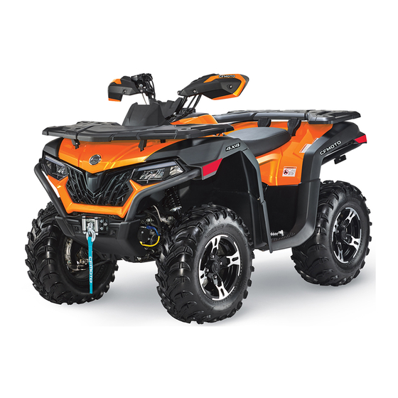
SPECIFICATION Specification CFORCE 600 CFORCE 600 TOURING Item CF600AU-3S CF600AU-3L 2035 mm 2235 mm Overall Length 1180 mm 1180 mm Overall Width 1220 mm 1390 mm Overall Height 1280 mm 1480 mm Wheel Base 270 mm Ground Clearance 3625 mm… -
Page 15
SPECIFICATION CFORCE 600 CFORCE 600 TOURING Item CF600AU-3S CF600AU-3L Bore × Stroke 91 mm × 89.2 mm Displacement 580 cc Compression Ratio 10.68 : 1 Starting Type ECU ignition Splash lubrication Lubrication Type Engine Coolant: Type Commercially available – Safe for aluminum engines Coolant Volume 2.3 qt ( 2.18 L ) -
Page 16
SPECIFICATION CFORCE 600 CFORCE 600 TOURING Item CF600AU-3S CF600AU-3L Rear gear case Oil: SAE80W/90GL-5 Type 6.7 oz ( 200 mL ) Volume: Periodic Oil Change 6.7 oz ( 200 mL ) Front Gear Case Oil: SAE80W/90GL-5 Type 7.7 oz ( 230 mL ) Volume 7.7 oz ( 230 mL ) -
Page 17
SPECIFICATION CFORCE 600 CFORCE 600 TOURING Item CF600AU-3S CF600AU-3L Spark Plug Type DCPR8E/NGK Spark Plug Gap 0.8 mm ~ 0.9 mm CVT+gear shift Transmission Gear Shift/Order Manual L/H/N/R/P 0.67 ~ 3.02 CVT Ratio Transmission 2.533 Low Gear Gear Ratio 1.35 High Gear 2.071… -
Page 18
SPECIFICATION CFORCE 600 CFORCE 600 TOURING Item CF600AU-3S CF600AU-3L Tire Pressure: Front 45 kPa Rear 45 kPa Front: hydraulic disc Brake System: Rear: hydraulic disc Foot Brake Type / Operation Front/rear united brake Operated by right foot Hand Brake Type / Operation… -
Page 19
Hydraulic damping / oil damper Rear Shock Absorber Hydraulic damping / oil damper Wheel Travel: Front Wheel Travel 160 mm Rear Wheel Travel 210 mm Electrical System: ECU ignition Ignition Charging A/C 600 Watt @ 5000 rpm 12 Vdc / 30 Amp Hr Battery… -
Page 20
SPECIFICATION CFORCE 600 CFORCE 600 TOURING Item CF600AU-3S CF600AU-3L Light System: LED 14.4W×2 Head Lamp, Low Beam LED 28.5W×4 Head Lamp, High Beam LED 3.6W×2 Front Position Light LED 2.9W×2 / LED 2W×2 Tail Light/Brake Light LED and LCD — non-maintenance… -
Page 21
OPERATOR SAFETY Operator Safety WARNING Failure to heed the warnings contained in this manual can result in serious injury or death. An ATV is not a toy and can be hazardous to operate. This vehicle handles differently from other vehicles, such as motorcycles and cars. -
Page 22
OPERATOR SAFETY Equipment Modifications CFMOTO is concerned with the safety of our customers and for the general public. Therefore, we strongly recommend that consumers do not install on a vehicle, any equipment that may increase the speed or power of the vehicle, or make any other modifications to the vehicle for these purposes. Any modifications to the original equipment of the vehicle create a substantial safety hazard and increase the risk of body injury. -
Page 23
OPERATOR SAFETY Safety Training When you purchased your new ATV, your dealer offered a hands-on safety training course that covers all aspects of vehicle safety. You were also provided with printed materials that explain safe operating procedures. You should review this information on a regular basis. If you purchased a used ATV from a party other than a dealer, you can request safety training from any authorized dealer. -
Page 24
OPERATOR SAFETY has completed a certified safety training course. • Never operate an ATV without wearing an approved helmet that fits properly . Always wear eye protection (goggles or face shield), gloves, boots, a long-sleeved shirt or jacket, and long pants. •… -
Page 25
OPERATOR SAFETY • Never go over the top of a hill at high speed. • Always follow proper procedures for going downhill and for braking on hills. Check. the terrain carefully before you start down a hill. Shift your weight backward. Never go down a hill at high speed. Avoid going down a hill at an angle, which would cause the vehicle to lean sharply to one side. -
Page 26
OPERATOR SAFETY • Wet brakes may have reduced stopping ability. Test your brakes after leaving water. If necessary, apply them lightly several times while driving slowly to allow friction to dry out the pads. • Always check for obstacles or people behind the ATV before operating in reverse. When it’s safe to proceed in reverse, move slowly and avoid turning at sharp angles. -
Page 27
OPERATOR SAFETY WARNING POTENTIAL HAZARD: Operating this ATV without proper instruction. WHAT CAN HAPPEN: The risk of an accident is greatly increased if the operator does not know how to operate the ATV properly in different situations and on different types of terrain. HOW TO AVOID THE HAZARD: Beginning and inexperienced operators should complete a certified training course offered by a dealer. -
Page 28
OPERATOR SAFETY WARNING POTENTIAL HAZARD: Carrying a passenger on an ATV that is not designed for carrying a passenger. WHAT CAN HAPPEN: A passenger riding on the ATV could be ejected from the vehicle unexpectedly or make contact with moving components, both of which can result in severe injury or death. -
Page 29
OPERATOR SAFETY WARNING POTENTIAL HAZARD: Operation on paved surfaces such as sidewalks, trails parking lots, or public highways and streets. WHAT CAN HAPPEN: ATV tires are designed for off-road use. Driving on paved surfaces greatly affects how an ATV handles, which can result in loss of control and/or an accident. -
Page 30
OPERATOR SAFETY WARNING POTENTIAL HAZARD: Operating this ATV without wearing an approved helmet, eye protection, and protective clothing. WHAT CAN HAPPEN: Operating an ATV without an approved helmet increases the risk of a severe head injury or death in the event of an accident. Operating without eye protection could result in an accident and could increase the chance of a severe eye injury in the event of an accident. -
Page 31
OPERATOR SAFETY WARNING POTENTIAL HAZARD: Operating the ATV after consuming alcohol or drugs. WHAT CAN HAPPEN: Consumption of alcohol and/or drugs could seriously affect operator judgment. Reaction time may be slower and operator balance and perception could be affected. Consumption of alcohol and/or drugs before or while operating an ATV could result in an accident causing severe injury or death. -
Page 32
OPERATOR SAFETY WARNING POTENTIAL HAZARD: Operating the ATV at excessive speeds. WHAT CAN HAPPEN: Excessive speed increases the operator’s chance of losing control of the ATV, which can result in an accident. HOW TO AVOID THE HAZARD: Always operate the ATV at a speed that’s proper for the terrain, visibility and operating conditions, and your experience. -
Page 33
OPERATOR SAFETY WARNING POTENTIAL HAZARD: Failure to inspect the ATV before operating. Failure to properly maintain the ATV. WHAT CAN HAPPEN: Poor maintenance increases the possibility of an accident or equipment damage. HOW TO AVOID THE HAZARD: Always inspect your ATV before each use to make sure it’s in safe operating condition. Always follow the inspection and maintenance procedures and schedules described in the owner’s manual. -
Page 34
OPERATOR SAFETY WARNING POTENTIAL HAZARD: Failure to use extra caution when operating the ATV on unfamiliar terrain. WHAT CAN HAPPEN: Unfamiliar terrain may contain hidden rocks, bumps, or holes that could cause loss of control or overturn. HOW TO AVOID THE HAZARD: Travel slowly and use extra caution when operating on unfamiliar terrain. -
Page 35
OPERATOR SAFETY WARNING POTENTIAL HAZARD: Failure to use extra caution when operating on excessively rough, slippery or loose terrain. WHAT CAN HAPPEN: Operating on excessively rough, slippery or loose terrain could cause loss of traction or loss of control, which could result in an accident or overturn. -
Page 36
OPERATOR SAFETY WARNING POTENTIAL HAZARD: Turning improperly. WHAT CAN HAPPEN: Improper turns could cause loss of control and lead to a collision or overturn. HOW TO AVOID THE HAZARD: Always follow proper procedures for turning as described in the owner’s manual. Practice turning at slow speeds before attempting to turn at faster speeds. -
Page 37
OPERATOR SAFETY WARNING POTENTIAL HAZARD: Climbing excessively steep hills or climbing hills improperly. WHAT CAN HAPPEN: Improper hill climbing could cause loss of control or overturn. HOW TO AVOID THE HAZARD: Never operate on hills too steep for the ATV or for your abilities. Practice on smaller hills before attempting large hills. -
Page 38
OPERATOR SAFETY WARNING POTENTIAL HAZARD: Traveling down excessively steep hills. WHAT CAN HAPPEN: Improper downhill travel could cause loss of control or overturn. HOW TO AVOID THE HAZARD: Never operate on hills too steep for the ATV or for your abilities. Practice on smaller hills before attempting large hills. -
Page 39
OPERATOR SAFETY WARNING POTENTIAL HAZARD: Improperly crossing hills and turning on hills. WHAT CAN HAPPEN: Improperly crossing or turning on hills could cause loss of control or overturn. HOW TO AVOID THE HAZARD: Never attempt to turn the ATV around on any hill until you’ve mastered the turning technique on level ground as described in the owner’s manual. -
Page 40
OPERATOR SAFETY WARNING POTENTIAL HAZARD: Stalling, rolling backwards or improperly dismounting while climbing a hill. WHAT CAN HAPPEN: The vehicle could overturn. HOW TO AVOID THE HAZARD: Maintain a steady speed when climbing a hill. IF ALL FORWARD SPEED IS LOST: Close the throttle. -
Page 41
OPERATOR SAFETY WARNING POTENTIAL HAZARD: Improperly operating over obstacles. WHAT CAN HAPPEN: Operating over obstacles could cause loss of control or overturn. HOW TO AVOID THE HAZARD: Before operating in a new area, check for obstacles. Avoid operating over large obstacles such as rocks and fallen trees when possible. -
Page 42
OPERATOR SAFETY WARNING POTENTIAL HAZARD: Skidding or sliding. WHAT CAN HAPPEN: Skidding or sliding can cause loss of control. If the tires regain traction unexpectedly, the ATV could overturn. HOW TO AVOID THE HAZARD: On slippery surfaces such as ice, travel slowly and use extra caution to reduce the chance of skidding or sliding out of control. -
Page 43
OPERATOR SAFETY WARNING POTENTIAL HAZARD: Operation of the ATV through deep or fast-flowing water. WHAT CAN HAPPEN: The tires may float, causing loss of traction and loss of control, which can lead to an accident or overturn. HOW TO AVOID THE HAZARD: Avoid operating the ATV through deep or fast-flowing water. -
Page 44
OPERATOR SAFETY WARNING POTENTIAL HAZARD: Improperly operating in reverse. WHAT CAN HAPPEN: The ATV could collide with an obstacle or person, resulting in severe injury. HOW TO AVOID THE HAZARD: Before shifting into reverse gear, always check for obstacles or people behind the ATV. When it’s safe to proceed, back slowly. -
Page 45
OPERATOR SAFETY WARNING POTENTIAL HAZARD: Operating the ATV with improper modifications. WHAT CAN HAPPEN: Improper installation of accessories or modification of the ATV may cause changes in handling which could lead to an accident. HOW TO AVOID THE HAZARD: Never modify the ATV through improper installation or use of accessories. All parts and accessories added to the vehicle must be genuine parts or equivalent components designed for use on this ATV and should be installed and used according to approved instructions. -
Page 46
OPERATOR SAFETY WARNING POTENTIAL HAZARD: Operating on frozen bodies of water. WHAT CAN HAPPEN: Severe injury or death can result if the ATV and/or the operator fall through the ice. HOW TO AVOID THE HAZARD: Never operate the ATV on a frozen body of water. -
Page 47
OPERATOR SAFETY WARNING Leaving the keys in the ignition can lead to unauthorized use of the vehicle, resulting in serious injury or death. Always remove the ignition key when the vehicle is not in use. WARNING After any overturn or accident, have a qualified service dealer inspect the entire vehicle for possible damage, including (but not limited to) brakes, throttle and steering systems. -
Page 48
OPERATOR SAFETY Safe Riding Gear Always wear clothing suited to the type of riding. ATV riding requires special protective clothing for comfort and to reduce the chance of injury: Helmet Your helmet is the most important piece of protective gear for safe riding. -
Page 49
SAFETY DECALS & LOCATIONS Safety Decals and Locations Warning decals have been placed on the ATV for your protection. Read and follow the instructions on each decal carefully. If a decal becomes illegible or comes off, contact your dealer to purchase a replacement. -
Page 50
SAFETY DECALS & LOCATIONS TYPE I TYPE II… -
Page 51
SAFETY DECALS & LOCATIONS TYPE I TYPE II… -
Page 52
SAFETY DECALS & LOCATIONS TYPE I TYPE II… -
Page 53
SAFETY DECALS & LOCATIONS TYPE I TYPE II… -
Page 54
SAFETY DECALS & LOCATIONS TYPE I TYPE II… -
Page 55
SAFETY DECALS & LOCATIONS TYPE I TYPE II… -
Page 56
SAFETY DECALS & LOCATIONS… -
Page 57
FEATURES & CONTROLS Features & Controls Left Hand Controls (Without turning light) Engine Stop Switch When the switch is at position, the engine shuts off. When the switch is at position, the engine can be started. Horn Button Press the button, the horn will sound. -
Page 58
FEATURES & CONTROLS Headlight Switch The headlight switch consists of 4 positions: : When the switch is at this position, Hi beam, front position light, tail light, and license plate light are on. : When the switch is at this position, Lo beam, front position light, tail light, and license plate light are on. -
Page 59
FEATURES & CONTROLS Override Button The engine is normally limited when operating in 4WD-LOCK If conditions require more engine power in 4WD-LOCK: • Release the throttle and press the button to override the speed limiting function. While this button is depressed, the override indicator light will come on. -
Page 60
FEATURES & CONTROLS Left Hand Controls (With turning light) Hazard Switch Press the button . Front turn lights, rear turn lights and turn signal indicators on dashboard flash. Engine Stop Switch When the switch is at position, the engine shuts off. When the switch is at position, the engine can be started. -
Page 61
FEATURES & CONTROLS Headlight Switch The headlight switch consists of 4 positions: : When the switch is at this position, Hi beam, front position light, tail light, and license plate light are on. : When the switch is at this position, Lo beam, front position light, tail light, and license plate light are on. -
Page 62
FEATURES & CONTROLS Override Button The engine is normally limited when operating in 4WD-LOCK If conditions require more engine power in 4WD-LOCK: • Release the throttle and press the button to override the speed limiting function. While this button is depressed, the override indicator light will come on. -
Page 63
FEATURES & CONTROLS Right Hand Controls Front Brake The front brake lever is located on the right handlebar and controls only the front brakes. Pull it toward the handlebar to apply the front brake. When squeezed, the lever or pedal should feel firm. Any sponginess would indicate a possible fluid leak or low master cylinder fluid level, which must be corrected before riding. -
Page 64
FEATURES & CONTROLS Four Wheel Drive (4WD) System Switch This ATV is equipped with on-command “2WD”/”4WD” and “LOCK”/”4WD” switches: • Two-wheel drive (2WD) : Power is supplied to the rear wheels only. The mode lever (A) is moved to the left and the switch button is outward. -
Page 65
FEATURES & CONTROLS Throttle Lever Once the engine is running, movement of the throttle lever will increase the engine speed. Regulate the speed of the machine by varying the throttle position. Because the throttle is spring loaded, the machine will decelerate, and the engine will return to an idle any time the hand is removed from the throttle lever. -
Page 66
FEATURES & CONTROLS Parking Brake Hydraulic parking brake is mounted on the right hand brake. To apply parking brake, grasp tightly the right hand brake first, and press foot brake at the same time, then press the hydraulic parking brake by left hand. -
Page 67
FEATURES & CONTROLS Mechanical Speed Limiter A mechanical speed limiter keeps the throttle from fully opening, even when the throttle lever is pushed to maximum travel. Turning in the screw limits the throttle lever travel, which reduces the maximum engine power available and decreases the maximum speed of the ATV. -
Page 68
FEATURES & CONTROLS Foot Brake The foot brake pedal is located on the right side floor board of the vehicle. Pushing down on the pedal applies the front and rear brakes at the same time. When applied, the pedal should feel firm. A soft brake pedal would indicate a possible fluid leak or low master cylinder fluid level, which must be corrected before riding. -
Page 69
FEATURES & CONTROLS Foot Brake Reservoir Fluid Level Check NOTE Remove the front access cover and then check the fluid level. When checking the fluid level, the ATV must be on level ground. If fluid level is lower than the “lower”mark , add DOT4 brake fluid. -
Page 70
FEATURES & CONTROLS Fuel Tank Fuel tank cap is located at the front of the vehicle. Open the fuel tank cap to fill fuel. Fuel Minimum Octane Rating The recommended fuel for your ATV is minimum 89 Octane unleaded (maximum 10% ethanol is allowed). Non-oxygenated (ethanol-free) fuel is recommended for best performance in all conditions. -
Page 71
FEATURES & CONTROLS Fuel Safety WARNING Gasoline is highly flammable and explosive under certain conditions. • Always exercise extreme caution whenever handling gasoline. • Always refuel with the engine stopped, and outdoors or in a well ventilated area. • Never carry a plastic container with gasoline in the racks while riding. Static electricity between the rack and container could cause a spark. -
Page 72
FEATURES & CONTROLS Transmission Gear Selector The transmission gear selector is located on the left side of the vehicle. CAUTION Always stop the ATV and press the foot brake pedal before shifting the transmission. Shifting gears with the engine speed above idle or while the vehicle is moving could cause transmission damage. -
Page 73
FEATURES & CONTROLS Parking To park the ATV, stop the engine, press the foot brake, and shift the gear selector Lever into the park position. CAUTION When shifting the transmission in PARK, always push the brake pedal. Shake the vehicle forward and backward to verify that park is engaged. -
Page 74
FEATURES & CONTROLS CVT System This vehicle has a Continuously Variable Transmission (CVT) system that utilizes a belt and clutch pulleys to automatically vary transmission ratios, allowing infinite variability between the highest and lowest vehicle speeds with no discrete steps or shifts. The CVT consists of a primary clutch , which is an advanced form of centrifugal clutch that is mounted to the engine crankshaft… -
Page 75
FEATURES & CONTROLS Avoiding CVT drive belt and component problems CVT clutch and belt life can be dramatically extended by avoiding these common operating mistakes: CVT Fail Reason How To Avoid CVT Failure Attempting to load the vehicle onto a truck bed Shift transmission to low gear during loading of the ATV to or tall trailer in high gear. -
Page 76
FEATURES & CONTROLS CVT Fail Reason How To Avoid CVT Failure Stuck in mud or snow. Shift the transmission to low gear, and carefully use fast, aggressive throttle application to engage clutch. WARNING: Excessive throttle may cause loss of control and vehicle overturn. Climbing over large objects from a stopped position. -
Page 77
FEATURES & CONTROLS Vehicle Features Main Switch The functions of the main key switch positions are as follows: : All electrical circuits are switched on. The engine can be started at this position. The key cannot be removed in this position. : All electrical circuits are switched off. -
Page 78
FEATURES & CONTROLS Front Storage Box / Rear Storage Box This vehicle is equipped with storage boxes on the front right side and the rear position. -
Page 79
FEATURES & CONTROLS Trailer Power Socket This vehicle is equipped with 7-pin trailer power socket, located under the rear cargo rack. The socket wires are configured to this standard as shown in the image provided . An accessory trailer power converter is required for trailers that do not have a 7-pin connector. -
Page 80
FEATURES & CONTROLS Winch This vehicle is equipped with a 3000-lb winch. The winch control is located on the left handle bar. To preserve battery power, only operate the winch when the engine is running. Please consult with your dealer on the use of the winch before using your vehicle. -
Page 81
FEATURES & CONTROLS • Prior to initiating winching operation be sure any element which can interfere with safe winching is removed. • Do not disengage clutch if winch is under load or wire rope is in tension. • Take your time. Sloppy rigging causes accidents. •… -
Page 82
FEATURES & CONTROLS Alarm This vehicle is configured with an alarm that performs the following functions: ≥ • When oil pressure signal is in GND, and RPM 1000 r/min, alarm sounds one short/time. When the oil pressure rises to the normal range, the alarm disappears. >… -
Page 83
FEATURES & CONTROLS Front panel access Your vehicle is equipped with an access panel on the front rack. To remove the panel: 1. Lift and pull the rubber retaining strap away from the panel until the strap releases from the front tab. 2. -
Page 84
FEATURES & CONTROLS Dashboard Indicators and Warnings… -
Page 85
FEATURES & CONTROLS 1 Engine RPM 10 Turning light, RH 19 Gear position indicator 2 Clock 11 Drive mode 20 Coolant Temperature 3 Turning light, LH 12 EPS indicator 21 SEL — mode select button 4 Neutral indicator 13 Parking brake indicator 22 Override indicator 5 High beam indicator 14 ADJ — mode adjust button… -
Page 86
FEATURES & CONTROLS Neutral indicator — This indicator displays when the transmission is in neutral. High beam indicator — This indicator illuminates when the headlight switch turns to high beam position. EFI fault indicator — This indicator displays when a fault occurs in the Electronic Fuel Injection system. Please stop the vehicle and contact your dealer to eliminate the fault. -
Page 87
FEATURES & CONTROLS Turning light, RH (If equipped) — When switch turns to right turning light position, the indicator is on. Drive mode — Display the current drive mode, there are 3 drive modes, 2WD, 4WD and 4WD-LOCK EPS fault indicator — This indicator displays when a fault occurs in the Electronic Power Steering system. -
Page 88
FEATURES & CONTROLS Rider Information Center — Rider Information Center. This dashboard section can be toggled using the ‘SEL’ button to display: ‘TOTAL’ -The odometer accumulated vehicle distance traveled in miles/kilometers, ‘TRIP’ — The trip distance traveled, ‘H’ — The accumulated engine run time, ‘V’ — Battery voltage, ‘Brightness’ — Set the dashboard display brightness using the ‘ADJ’… -
Page 89
FEATURES & CONTROLS Gear position indicator — Display the current gear position. Coolant Temperature — This dashboard section displays the current coolant temperature, ‘C’ is low temperature, ‘H’ is high temperature. Both over-low and over-high are abnormal. Idle the vehicle to warm the engine when it’s too cold, and park the vehicle when it’s too hot to prevent the coolant from boiling. -
Page 90
FEATURES & CONTROLS Dashboard Navigation / Settings / Adjustments Item Display Operation Result Odometer TOTAL Short press Shift to trip TRIP Short press Shift to engine hour Engine hour Trip distance TRIP Long press Trip resets to be zero TRIP Engine hour Short press Shift to fault code… -
Page 91
OPERATION OF YOUR ATV Operation of your ATV Break-In Period The break-in period for your new ATV is very important. Careful treatment of a new engine at the beginning of ownership will result in more efficient performance and longer life. Perform the following procedures carefully: 1. -
Page 92
OPERATION OF YOUR ATV CAUTION During the break-in period: • Do not load or tow cargo. • Do not operate at sustained full throttle. Damage to engine parts or decrease engine life may result if excessive wide open throttle is used during the first 20 hours of use. •… -
Page 93
OPERATION OF YOUR ATV Pre-Ride Inspection Before each use of the vehicle, a best practice is to check the vehicle according to the “Perform daily before operating the vehicle” checklist in maintenance sheet. WARNING If a proper inspection is not done before each use, severe damage to the vehicle, severe injury, or death could result. -
Page 94
OPERATION OF YOUR ATV Starting the Engine Starting a Cold Engine WARNING Engine exhaust contains poisonous carbon monoxide and can cause loss of consciousness resulting in severe injury or death. Never run an engine in an enclosed area. CAUTION Operating the vehicle immediately after starting could cause engine damage. Allow the engine to warm up for several minutes before operating the vehicle. -
Page 95
OPERATION OF YOUR ATV NOTE Do not activate the starting system more than 10 seconds on each attempt. If the engine fails to start, release the start switch, pause a few seconds before the next attempt, then push the start switch again. Each attempt should be as short as possible to preserve battery energy. -
Page 96
OPERATION OF YOUR ATV Gear Selector Operation Shifting CAUTION To avoid transmission damage, return the throttle to the closed position, stop the vehicle, and apply the foot brake before shifting. NOTE Low gear is the preferred transmission gear selection for all forward motion other than prolonged high speed travel. -
Page 97
OPERATION OF YOUR ATV Shifting out of Park 1. Verify the throttle is closed. 2. Apply the foot brake. 3. Shift to the desired gear by moving the gear selector along the shift guide. Shifting: Neutral to High Gear 1. Verify the throttle is closed and the vehicle is stopped completely. 2. -
Page 98
OPERATION OF YOUR ATV 4. Check behind you for people or obstacles, then release the foot brake pedal. 5. Apply the throttle lever gradually and continue to watch behind you while moving backward. WARNING When you shift into reverse, make sure there are no obstacles or people, and the area is safe behind you. When it is safe to proceed, go slowly. -
Page 99
OPERATION OF YOUR ATV Hauling Cargo Your vehicle is equipped with front and rear cargo racks, and a hitch receptacle for towing. Follow these guidelines for hauling and towing of cargo: WARNING Overloading the vehicle, carrying or towing cargo improperly, can alter vehicle handling and may cause loss of control or brake instability. -
Page 100
OPERATION OF YOUR ATV • Carrying a load on only the front rack or the rear rack may cause an imbalanced condition and increases the possibility of vehicle overturn. Balance loads proportionally between the front rack and the rear rack, but do not exceed the stated load capacity. •… -
Page 101
OPERATION OF YOUR ATV Load Distribution Your ATV has been designed to carry or tow a certain amount of load. Always: • Read and understand the load distribution warnings listed on the warning labels. • Never exceed the specified weights. •… -
Page 102
OPERATION OF YOUR ATV Driving Safely Responsibilities of the operator As the operator of this ATV, your common sense, judgment, and abilities are the only factors that will prevent injury to yourself, to others around you, and/or damage to the vehicle or environment. Recreational, group, and distance riding One of the benefits of this vehicle is that it can take you off-road away from most communities. -
Page 103
OPERATION OF YOUR ATV Practice The driving procedures described in this manual should be practiced at slow speed many times in a large area with no obstacles. If an incorrect technique is used, your ATV may continue to go straight. If the ATV does not turn, come to a stop and then practice the procedure again. -
Page 104
OPERATION OF YOUR ATV Driving procedure 1. Sit upright with both feet on the footrests and both hands on the handlebars. 2. Start the engine and allow it to warm up. Apply the foot brake, then shift the transmission into low gear. 3. -
Page 105
OPERATION OF YOUR ATV Making Turns To make a turn, steer in the direction of the turn, leaning your upper body to the inside of the turn while supporting your weight on the outer footrest. This technique alters the balance of traction between the wheels, allowing turn to be made smoothly. -
Page 106
OPERATION OF YOUR ATV ATV turning dynamics To achieve maximum traction while operating in 2WD or 4WD, the two rear wheels perform as one axle and turn together at the same speed. Furthermore, when operating in 4WD-LOCK mode, the front wheels will also turn together at the same speed. -
Page 107
OPERATION OF YOUR ATV Driving in reverse To operate in reverse: 1. Ensure the throttle is closed and the vehicle is stopped completely. 2. Apply the foot brake, then shift the transmission into reverse gear. 3. Check for obstacles or people behind the vehicle. 4. -
Page 108
OPERATION OF YOUR ATV Driving on Slippery Surfaces Whenever riding on slippery surfaces such as wet trails, loose gravel, sand, or during freezing weather, follow these precautions: • Slow down when entering slippery areas. • Maintain a high level of alertness, reading the trail and avoiding quick, sharp turns which can cause skids. -
Page 109
OPERATION OF YOUR ATV Driving on rough terrain Whenever driving on rough surfaces such as trails with large rocks or other obstacles, follow these precautions: • Slow down when encountering rough terrain. • Maintain a high level of alertness, reading the trail in front of you as you drive. -
Page 110
OPERATION OF YOUR ATV Driving over obstacles Be alert! Learn to look ahead and to read the terrain as you drive. Be constantly alert for hazards such as logs, rocks, and low hanging branches. Never attempt to cross over an obstacle higher than the ground clearance of the vehicle. -
Page 111
OPERATION OF YOUR ATV Driving through water Yo u r AT V c a n o p e r a t e t h r o u g h w a t e r w i t h a m a x i m u m recommended depth equal to the bottom of the footrests. -
Page 112
OPERATION OF YOUR ATV Drying the CVT system after submersion If water has been ingested into the CVT housing, the drive belt will likely slip and poor performance will result. To expel water and dry the CVT housing: • Drain the CVT housing. •… -
Page 113
OPERATION OF YOUR ATV Driving Uphill Whenever traveling uphill, follow these precautions: • Always travel straight uphill. • Avoid steep hills (22° maximum). • Keep both feet on the footrests. • Shift your weight forward. • Proceed at a steady rate of speed and throttle opening. •… -
Page 114
OPERATION OF YOUR ATV If the ATV begins rolling backwards: Keep your weight uphill. Never apply engine power. Never apply the foot brake while rolling backwards. Apply the front brake. When fully stopped, apply the foot brake, and then shift gear selector into the parking position. -
Page 115
OPERATION OF YOUR ATV Sidehilling WARNING Improperly crossing hills or turning on hills can result in loss of control or vehicle overturn, resulting in severe injury or death. Avoid crossing the side of a hill when possible. Follow proper procedures as outlined in the owner’s manual. -
Page 116
OPERATION OF YOUR ATV Driving downhill When traveling down a hill, follow these precautions: • Never operate on hills over 22 degrees incline or hills too steep for your abilities. • Slow down. • Shift your weight to the rear of the vehicle. •… -
Page 117
OPERATION OF YOUR ATV Turning Around on a Hill One maneuver that can be used when it’s necessary to turn around if stranded while climbing a hill is the K-turn: 1. Release the throttle, then apply the hand and foot brake while keeping your body weight uphill. -
Page 118
OPERATION OF YOUR ATV Parking on an lncline Avoid parking on an incline if possible. If it’s unavoidable, follow these precautions: • Turn the engine off. • Place the gear selector to parking position. • Always block the rear wheels on the downhill side as shown. CAUTION The rear output shaft is locked when the transmission is in the parking position. -
Page 119
MAINTENANCE Maintenance Schedule Periodic maintenance schedule Careful periodic maintenance will help keep your vehicle in the safest, most reliable condition. Inspection, adjustment and lubrication of important components are explained in the periodic maintenance chart. Inspect, clean, lubricate, adjust, and replace parts as necessary. When inspection reveals the need for replacement parts, please use genuine parts available from your dealer. -
Page 120
MAINTENANCE NOTE Pay special attention to the oil level. A rise in oil level during cold weather can indicate contaminants collecting in the oil sump or crankcase. Change oil immediately if the oil level begins to rise. Monitor the oil level, and if it continues to rise, discontinue to use and determine the cause or see your dealer. -
Page 121
MAINTENANCE KEY POINTS OF LUBRICATION SCHEDULE: Check all components at the intervals outlined in the Periodic Maintenance Schedule. Items not listed in the schedule should be lubricated at the general lubrication interval. • Change lubricants more often under severe use, such as wet or dusty conditions. •… -
Page 122
MAINTENANCE Pre-Ride Maintenance Checklist Perform these inspections before operating the vehicle: Maintenance before operation Item Hour Calendar Miles (km) Remarks Pre-Ride ■ Steering system Pre-Ride ■ Throttle return Pre-Ride Front suspension and axles Visually inspect, test, Pre-Ride Rear suspension and axles or check components. -
Page 123
MAINTENANCE Maintenance before operation Item Hour Calendar Miles (km) Remarks Inspect. If deposits are visible, clean intake Pre-Ride ► Air box sediment tube tubes, air box, and replace air filter. Inspect. If deposits are visible, drain / clean Pre-Ride ► CVT sediment tube the CVT or have it serviced by a dealer. -
Page 124
MAINTENANCE Break-In Maintenance Checklist Perform these maintenance items when the vehicle break-in is completed: Break-in Maintenance (Perform at the interval that arrives first) Item Hour Calendar Miles (km) Remarks Lubricate all grease 200 (320) General lubrication points, pivots, cables, etc. Change oil and filter. -
Page 125
MAINTENANCE Break-in Maintenance (Perform at the interval that arrives first) Item Hour Calendar Miles (km) Remarks Check terminals, 200 (320) Battery clean, test battery condition if required. Inspect for proper rpm. See dealer for 200 (320) ■ Idle condition service if out of spec or erratic. -
Page 126
MAINTENANCE Periodic Maintenance Schedule Perform these maintenance items when the vehicle break-in is completed: Periodic Maintenance Intervals (Perform at the interval that arrives first) Item Hour Calendar Miles (km) Remarks Monthly 100 (160) ► Brake pads Inspect pad thickness. Check terminals. Clean and test 200 (320) Battery… -
Page 127
MAINTENANCE Periodic Maintenance Intervals Item (Perform at the interval that arrives first) Hour Calendar Miles (km) Remarks Inspect level. Change yearly if hours or 500 (800) ► Front gear case oil distance interval is not met. Inspect level. Change yearly if hours or 500 (800) ►… -
Page 128
MAINTENANCE Periodic Maintenance Intervals Item (Perform at the interval that arrives first) Hour Calendar Miles (km) Remarks Inspect. clean external surfaces. Clean more 500 (800) ► Radiator frequently if subjected to severe use. 500 (800) Inspect. Lubricate. ■ Steering system L u b r i c a t e . -
Page 129
MAINTENANCE Periodic Maintenance Intervals (Perform at the interval that arrives first) Item Hour Calendar Miles (km) Remarks Inspect. Replace 1500 (2400) ► ■ CVT drive belt as necessary. See dealer for service. Clean and Inspect pulleys. Replace 100h 500 (800) ■… -
Page 130
MAINTENANCE Periodic Maintenance Intervals Item (Perform at the interval that arrives first) Hour Calendar Miles (km) Remarks Inspect fuel tank, cap, ● 100h 500 (800) Fuel system fuel pump and fuel pump relay. Inspect. Replace if 100h 2000 (3200) Spark plug worn or fouled. -
Page 131
MAINTENANCE Periodic Maintenance Intervals Item (Perform at the interval that arrives first) Hour Calendar Miles (km) Remarks Inspect for noise or 100h 1500 (2400) ► ■ Wheel bearings looseness Replace as necessary. Visually inspect belts and test latches. Clean latch 100h 2000 (3200) ►… -
Page 132
MAINTENANCE Periodic Maintenance Intervals (Perform at the interval that arrives first) Item Hour Calendar Miles (km) Remarks Inspect for proper rpm. See dealer for Idle condition service if out of spec or erratic. Inspect steering system. See dealer for service whenever ■… -
Page 133
MAINTENANCE Maintenance Procedures Engine oil check Always check and change the engine oil at the intervals outlined in the Maintenance Schedule. 1. Place the ATV on a level surface. 2. Start the engine and let it idle for (20 ~ 30) seconds. Stop the engine. -
Page 134
MAINTENANCE Engine oil change 1. Place the ATV on a level surface. 2. If the engine was running, wait a sufficient period for the oil to settle and cool. 3. Place an oil pan under the engine to collect the used oil. 4. -
Page 135
MAINTENANCE Oil filter replacement 1. Use wrench to unscrew bolts . Then remove cover remove oil filter Attention: Confirm cover O-ring is good, then install it into groove of the crankcase correctly. 2. Install new oil filter and use wrench to tighten cover bolts to the specified torque. -
Page 136
MAINTENANCE Engine valve train adjustment The intake and exhaust valve clearances change with use of the vehicle, which can result in improper fuel/air supply or engine noise. To prevent this, the valve clearances must be adjusted according to the maintenance schedule. -
Page 137
MAINTENANCE Gear case oil The gear cases must be checked for oil leaks before each ride. If an oil leak is found, have your dealer check and repair the ATV. Rear case oil measurement Because of its unique design, draining and filling the gear case is required to produce the correct lubricant level. -
Page 138
MAINTENANCE Front gear case oil measurement Because of its unique design, draining and filling the gear case is required to produce the correct lubricant level. Refer to ‘Rear gear case oil change’ NOTE: Oil filler bolt tightening torque: 18.4 ft-lb. (25 N•m). Front gear case oil change 1. -
Page 139
MAINTENANCE Cooling system Coolant level check 1. Place the ATV on a level surface. 2. Coolant reservoir is located on the front left of the vehicle. Check the coolant level in the coolant reservoir when the engine is cold as the coolant level will vary with engine temperature. -
Page 140
MAINTENANCE Front access cover Removal: Grasp the access cover edge, pull upward to release the grommet pins, then remove the front access cover A by direction of front of vehicle. Grasp the edge of front top cover B, pull upward to release the grommet pins, then remove the cover B by direction of front of vehicle. -
Page 141
MAINTENANCE Changing the coolant CAUTION After running the engine, never remove the radiator cap immediately. Wait for the engine to cool down before removing the radiator cap. Hot coolant can cause serious burns. 1. Place the ATV on a level surface. 2. -
Page 142
MAINTENANCE 8. Replace the coolant drain bolt washer if it is damaged, then install and tighten the coolant drain bolt, but do not torque to specification. 9. Reinstall the coolant reservoir hose. 10. Fill the recommended coolant into the radiator until it is full. NOTE When filling coolant, at the same time loosen the coolant drain bolt to draw out potential air bubbles inside the coolant hose until… -
Page 143
MAINTENANCE NOTE Recommended antifreeze: Any high quality ethylene glycol antifreeze containing corrosion inhibitors for aluminum engines. CFMOTO recommended coolant freeze protection level: -35 Antifreeze and distilled water mixing ratio: 1:1 Total Coolant Capacity (except coolant reservoir): 2.3 qt. (2.18 L) Coolant Change (except coolant reservoir): 2.22 qt. -
Page 144
MAINTENANCE Axle dust boots Check the protective boots for holes or wear. If any damage is found, have them replaced by your dealer. Rear : Front:… -
Page 145
MAINTENANCE Spark plug inspection To access the spark plug, the following components must be removed: Left Deco Panel Remove the expansion screws Remove the bolt Remove the cover ; Shifter Cover Remove the screw ; Remove the bolts ;… -
Page 146
MAINTENANCE Remove the cover ; Lower Side Cover Remove the bolts ; Remove the left lower side cover ;… -
Page 147
MAINTENANCE Removal Remove the spark plug cap. Use the spark plug wrench in the tool kit to remove the spark plug. Inspection The spark plug is an important engine component and is easy to inspect. The condition of the spark plug can indicate the condition of the engine. -
Page 148
MAINTENANCE Measure the electrode gap with a thickness gauge, and if necessary, adjust the gap to specification. NOTE: Spark plug gap : 0.8 mm ~ 0.9 mm Installation 1. Clean the gasket surface. Wipe off any grime from the threads. 2. -
Page 149
MAINTENANCE Spark plug removal to expel water from the engine If water has been ingested into the engine, it is important to remove the water as soon as possible by removing the spark plug and using the starter system to rotate the engine for a short period to expel water out of the cylinder. -
Page 150
MAINTENANCE Air filter element There is a check hose at the bottom of the air filter housing. If dust or water can be viewed in this hose, empty the hose and clean the air filter housing thoroughly. If the vehicle was submerged, please contact your local dealer to check for water inside the engine crankcase. -
Page 151
MAINTENANCE lubricant on the inside diameter of the air filter rubber seal. 10. Install the air filter and clamp onto the air filter housing inlet. Tighten the clamp securely. 11. Reinstall the air filter housing cover and spring clips. Verify the cover is installed correctly and is sealing properly. -
Page 152
MAINTENANCE Drying the air filter housing after submersion If water has been ingested into the air filter housing, Drain the air filter housing, remove the air filter, and thoroughly dry the components. Do not use compressed air. Contact your dealer if vehicle performance issues exist. -
Page 153
MAINTENANCE Spark Arrestor Clean spark arrestor while muffler and exhaust are in normal temperature. 1. Remove nut 2. Remove spark plug arrestor from muffler. 3. Tap the tailpipe lightly, and then use a wire brush to remove any carbon deposits from the spark arrestor portion of the tailpipe. -
Page 154
MAINTENANCE CVT air-outlet check hose If dust or water can be viewed in this hose , empty the hose and clean or drain the CVT housing. If the vehicle was submerged, contact your local dealer to check the CVT housing and components thoroughly. -
Page 155
MAINTENANCE Throttle freeplay adjustment Check the throttle freeplay at regular intervals. NOTE Check the engine idling speed after adjusting throttle lever freeplay. 1. Loosen nut 2. Turn adjustment nut to lever travel: = 3 mm ~ 5 mm. 3. Fasten nut Brake pad inspection Check the brake pads for damage and wear. -
Page 156
MAINTENANCE Brake system inspection Check the fluid level Insufficient brake fluid may let air enter the brake system, possibly causing the brakes to become ineffective. Before riding, check that the brake fluid is above the lower level and replenish when necessary. -
Page 157
MAINTENANCE Inspect brake fluid level Observe these precautions: 1. When checking the front brake fluid level, make sure the master cylinder reservoir is level by turning the handlebar until the steering is centered and the wheels are pointed forward. 2. Use only the designated quality brake fluid. Otherwise, the rubber seals may deteriorate, causing leakage and poor brake performance. -
Page 158
MAINTENANCE Brake fluid change Complete fluid replacement should be done only by trained service personnel. Have your dealer replace the following components during periodic maintenance or when they are damaged or leaking. • Replace the brake hoses every four years. Front lever free play The front brake lever should have a free play of 10 mm (0.4 in) at the lever end. -
Page 159
MAINTENANCE Parking brake RH parking brake When parking, stop the engine and grasp tightly the right hand brake, press foot brake at the same time, then press the hydraulic parking brake by left hand. WARNING Operating the ATV while the parking brake is engaged could result in an accident and serious injury or death. -
Page 160
MAINTENANCE Foot brake pedal height adjustment NOTE The top of the brake pedal should be positioned 95 mm ~ 100 mm above the top of the footrest. If it is not, have your dealer to adjust DANGER After servicing: • Make sure the brakes operate smoothly and that the freeplay 95 mm ~ 100 mm is correct. -
Page 161
MAINTENANCE Cable inspection and lubrication WARNING Inspect cables frequently. Replace damaged cables. Lubricate the inner cables and the cable ends. If the cables do not operate smoothly, ask your dealer to replace them. NOTE Recommended lubricant: SAE 10W/30 Suspension Pivot Lubrication Lubricating rear stabilizer bar. -
Page 162
MAINTENANCE Wheel and Tires Removal and installation Removal 1. Loosen the wheel nuts 2. Elevate the ATV and place a suitable stand under the frame. 3. Remove the nuts from the wheel. 4. Remove the wheel. Installation: 1. Install the wheel and the nuts. NOTE •… -
Page 163
MAINTENANCE Tire pressure Inspect the tire pressure before operation: Front: 6.5 psi (45 kPa) Rear: 6.5 psi (45 kPa) Tread depth Inspect the tread depth regularly and replace the tires if the minimum tread depth is less than: Minimum tread depth: 3/32 in. (3.0 mm) -
Page 164
MAINTENANCE Battery This machine is equipped with low maintenance battery which is located under the seat. Therefore, it is not necessary to check the electrolyte or add distilled water in the battery. If the battery seems to have discharged, consult your dealer. NOTE Battery specification: 12V 30Ah WARNING… -
Page 165
MAINTENANCE Battery maintenance guidelines: • If the vehicle will not be used for a month or longer, remove the battery and store it in a cool, dry place. Completely recharge the battery before reinstallation. • A special battery charger (constant low voltage/ampere) is required for recharging low maintenance batteries. -
Page 166
MAINTENANCE Battery Disassembly Turn off all electrical parts and the engine before disassembly. Disassembly (The L model) Remove the passenger and operator seats. Remove the expansion screws Remove the deco panel Remove bolt Remove the rear seat mounting bracket Remove the belt and electrode cover Remove the fixing bolt of battery negative wire together with the wire. -
Page 167
MAINTENANCE Assembly (The L model) Mount the battery in place. Mount the positive wire onto the battery positive bolt. Mount the negative wire onto the battery negative bolt. Mount the belt and electrode cover Mount the rear seat mounting bracket Mount the bolt Mount the deco panel Mount the expansion screws… -
Page 168
MAINTENANCE Disassembly (The S model) Remove the expansion screws Remove the deco panel Remove the bolt Remove the front seat assembling bracket Take out the belt and electrode protector Remove the fixing bolt of battery negative wire together with the wire. Remove the fixing bolt of battery positive wire together with the wire. -
Page 169
MAINTENANCE Fuse and Relay replacement 1. Relay / Fuse box is located under the front access cover. Main fuse 30A and EPS fuse 40A are located under the seat. 2. If a fuse is blown, turn off the main switch and install a new fuse of the specified amperage. -
Page 170
MAINTENANCE Relay / Fuse Box For vehicle without turning light… -
Page 171
MAINTENANCE Relay / Fuse Box For vehicle with turning light… -
Page 172
MAINTENANCE WARNING To prevent accidental short-circuit, turn off the main switch when checking or replacing a fuse. Headlight bulb replacement NOTE: Both headlight and taillight assy are LED lights, which cannot be repaired if damaged or failed. Please have your dealer replace the entire assembly when the LED light is damaged or failed. -
Page 173
MAINTENANCE Headlight beam adjustment WARNING It is advisable to have your dealer make this adjustment. Turn the adjusting screws can raise or lower the beam. Tail/brake light replacement: Tail/brake light bulb is LED, it can not be replaced separately. Replace the whole light as necessary. -
Page 174
MAINTENANCE Front and rear suspension adjustment Standard shock absorber The spring preload can be adjusted to suit the rider’s weight and riding conditions. NOTE When adjusting the rear shock absorbers, the rear wheels need to be removed. Adjust the spring preload as follows. To increase the spring preload, turn the adjusting ring in direction To decrease the spring preload, t urn the adjusting ring… -
Page 175
MAINTENANCE WARNING If your vehicle becomes immersed, major engine damage can result if the machine is not thoroughly inspected. Take the vehicle to your dealer before starting the engine. For example, if engine is not properly handled after immersion, starting will damage the engine. Fuel Evaporation System (EVAP) Your vehicle contains a fuel evaporation system (EVAP) that prevents fuel vapors from entering the atmosphere from the fuel tank and fuel system. -
Page 176
CLEANING & STORAGE Cleaning & Storage Cleaning the ATV Keeping your ATV clean will not only improve its appearance, but it can also extend the life of various components. With a few precautions, your ATV can be cleaned much like an automobile. Washing the ATV The best and safest way to clean your ATV is with a garden hose and a pail of mild soap and water. -
Page 177
CLEANING & STORAGE Waxing the ATV Your ATV can be waxed with any non-abrasive automotive paste wax. Avoid the use of harsh cleaners since they can scratch the body finish. CAUTION Certain products, including insect repellents and chemicals, will damage plastic surfaces. Use caution when using these products near plastic surfaces. -
Page 178
CLEANING & STORAGE Oil and Filter Warm the engine, then stop the engine and change the oil and filter. Air Filter/ Air Box Inspect and clean or replace air filter. Clean the air box and drain the sediment tube. Check fluid levels Inspect the following fluid levels and change if necessary: •… -
Page 179
CLEANING & STORAGE Lubricate Inspect all cables and lubricate with cable lubricant according to the product label directions. Grease the vehicle pivot points with all season grease. ‘Fog’ the engine 1. Remove the left side panel to access the spark plug. 2. -
Page 180
CLEANING & STORAGE Engine Anti-Freeze Test engine coolant strength and change if necessary. Coolant should be replaced every two years. Storage Area/Covers Set the tires to specified air pressure and support the ATV with tires 30 mm ~ 40 mm off the ground. Be sure the storage area is well ventilated and cover the machine with a ATV cover. -
Page 181
CLEANING & STORAGE Transporting the ATV Follow these procedures when transporting the vehicle: • Turn off the engine and remove the key to prevent loss during transporting. • Ensure the fuel cap is installed correctly and secure. • Ensure the seat is installed correctly and secure. •… -
Page 182
VEHICLE DIAGNOSIS Vehicle Issue Diagnosis This section is intended to guide an average owner to simple items that could cause operating problems. Diagnosis of vehicle issues may require the experience of a dealership technician. Please contact your dealer if a solution is not apparent. Engine doesn’t turn over Fail Reason How To Avoid Failure… -
Page 183
VEHICLE DIAGNOSIS Engine Stops or loses power Fail Reason How To Avoid Failure Overheated engine Clean radiator screen and core Clean engine exterior See your dealer Engine Turns Over, Fails to Start Fail Reason How To Avoid Failure Out of Fuel Refuel Clogged fuel valve or filter Inspect and clean or replace… -
Page 184
VEHICLE DIAGNOSIS Engine Backfires Fail Reason How To Avoid Failure Weak spark from spark plugs Inspect, clean and/or replace spark plugs Incorrect spark plug gap or heat range Set gap to specs or replace plugs Old or non-recommended fuel Replace with new fuel Incorrectly installed spark plug wires See your dealer Incorrect ignition timing… -
Page 185
VEHICLE DIAGNOSIS Engine Runs Irregularly, Stalls or Misfires Fail Reason How To Avoid Failure Kinked or plugged fuel vent line Inspect and replace Incorrect fuel Replace with recommended fuel Clogged air filter Inspect and clean or replace Reverse speed limiter malfunction See your dealer Electronic throttle control malfunction See your dealer… -
Page 186
VEHICLE DIAGNOSIS Engine Stops or Loses Power Fail Reason How To Avoid Failure Out of fuel Refuel Kinked or plugged fuel vent line Inspect and replace Water present in fuel Replace with new fuel Fouled or defective spark plugs Inspect, clean and/or replace spark plugs Worn or defective spark plug wires See your dealer Incorrect spark plug gap or heat range… -
Page 187
VEHICLE DIAGNOSIS EFI Malfunction Indicator Light The Electronic Fuel Injection system on your vehicle contains a self-diagnostic feature that will illuminate the malfunction indicator light ( M IL ) if it detects a problem. When this indicator is on, the fault code will display on the dashboard directly, record the fault code and contact your dealer for diagnosing. -
Page 188
VEHICLE DIAGNOSIS EPS Malfunction Indicator Light The Electronic Power Steering system on your vehicle contains a self-diagnostic feature that will illuminate the malfunction indicator light (MIL- ) if it detects a problem. In normal operation, the EPS indicator will be on after the ignition switch is turned to ON, but EPS will not work. -
Page 189
VEHICLE DIAGNOSIS EPS fault diagnosis and solution Trouble shooting Possible causes Repair procedures Improper plug connection Check the plugs and connections No steering assist Burnt fuse Replace fuse to handlebar Contact authorized dealer and replace the Failure of Controller, Motor or sensor parts. -
Page 190
CFMOTO LIMITED WARRANTY FOR USA CFMOTO Limited Warranty For USA Dear Customer, Thank you for purchasing a CFMOTO product, if any component on your vehicle is found to be defective in materials or workmanship within the terms and conditions of this Limited Warranty, the defective component will be repaired or replaced (at the option of CFMOTO) without charge for parts and/or labor at any authorized dealer located within the United States. -
Page 191
CFMOTO LIMITED WARRANTY FOR USA A. A 30-DAY WARRANTY coverage period applies to all new CFMOTO vehicles in relation to the vehicle’s: • Battery • Spark Plugs • Air Filters • Oil and Fuel Filters B. A 90-DAY WARRANTY coverage period applies to all new CFMOTO vehicles in relation to the vehicle’s: •… -
Page 192
CFMOTO LIMITED WARRANTY FOR USA 3.EXCLUSIONS FROM WARRANTY COVERAGE: Any Damage resulting from the following acts or circumstances is not covered by the CFMOTO POWERSPORTS, Inc., Limited Warranty: • Fire • Collision • Theft • Unavoidable natural disasters • Improper storage or transportation •… -
Page 193
CFMOTO LIMITED WARRANTY FOR USA 5.TRANSFER OR CONTINUATION OF WARRANTY: This warranty is transferable only under the following conditions: • Transfer information must be provided to an authorized CFMOTO POWERSPORT S, Inc. dealer, who will then forward the information to CFMOTO POWERSPORTS, Inc.. •… -
Page 194
CFMOTO LIMITED WARRANTY FOR USA 8.CUSTOMER ASSISTANCE: Any questions regarding your CFMOTO vehicle or related products should be directed to an authorized CFMOTO dealer. However, if a dealer is not available to answer customer concerns or address a technical issue with a CFMOTO vehicle or product, CFMOTO POWERSPORTS, Inc., customer representatives can be contacted directly at (763) 398-2690 or by e-mail: info@cfmoto-us.com.Please note that Customer Service cannot approve or deny warranty, and cannot provide technical repair data, diagnosis, instruction, or other information beyond what is provided in the Owner’s Manual. -
Page 195
CFMOTO LIMITED WARRANTY FOR USA 12. INTEGRATION: This limited warranty supersedes any and all oral, express, or written warranties, statements, or undertakings that may previously have been made, and contains the entire agreement of the parties with respect to the warranty of CFMOTO vehicles. Any and all warranties not contained in this Agreement are specifically excluded. -
Page 196
CFMOTO LIMITED WARRANTY FOR USA CALIFORNIA EVAPORATIVE EMISSIONS CONTROL WARRANTY STATEMENT YOUR WARRANTY RIGHTS AND OBLIGATIONS INTRODUCTION: The California Air Resources Board (CARB) and CFMOTO Powersports, Inc. (CFMOTO) are pleased to explain the evaporative emissions control system warranty on your 2020 and later-model year off-highway recreation vehicles (OHRVs). -
Page 197
CFMOTO LIMITED WARRANTY FOR USA As an owner, you are responsible for presenting your OHRV to a CFMOTO dealer as soon as a problem exists. The warranty repairs should be completed in a reasonable amount of time, not to exceed 30 days. As an OHRV owner, you should also be aware that CFMOTO may deny you warranty coverage if your OHRV or a part has failed due to abuse, neglect, improper maintenance or unapproved modifications. -
Page 198
CFMOTO LIMITED WARRANTY FOR USA U.S.A. EPA and CARB Emissions Control Limited Warranty This emissions limited warranty is in addition to the CFMOTO Powersports, Inc. standard limited warranty for your vehicle. CFMOTO Powersports, Inc. warrants that at the time it is first purchased, this emissions- certified vehicle is designed, built and equipped so it conforms to applicable U.S. -
Page 199
CFMOTO LIMITED WARRANTY FOR USA For exhaust emissions, emission-related components include any engine parts related to the following systems: • Air-induction system (excludes filters) • Ignition system (excludes spark plugs) • Fuel system (excludes filters) • Exhaust gas recirculation systems The following parts are also considered emission-related components for exhaust emissions: •… -
Page 200
CFMOTO LIMITED WARRANTY FOR USA THE REMEDIES SET FORTH IN THIS LIMITED WARRANTY ARE THE ONLY REMEDIES AVAILABLE TO ANY PERSON FOR BREACH OF THIS WARRANTY. CFMOTO POWERSPORTS, INC. SHALL HAVE NO LIABILITY TO ANY PERSON FOR INCIDENTAL, CONSEQUENTIAL OR SPECIAL DAMAGES OF ANY DESCRIPTION, WHETHER ARISING OUT OF EXPRESS OR IMPLIED WARRANTY OR ANY OTHER CONTRACT, NEGLIGENCE OR OTHER TORT OR OTHERWISE. -
Page 201
CFMOTO LIMITED WARRANTY FOR USA Some states do not allow limitations on how long an implied warranty lasts, so the above limitation may not apply if it is inconsistent with the controlling state law. This limited warranty excludes failures not caused by a defect in material or workmanship. -
Page 202
CFMOTO LIMITED WARRANTY FOR USA Noise Control System and Tampering Warranty time period: 1, 865 miles (3000 km) Federal law prohibits the following acts or causing thereof: (1)The removal or rendering inoperative by any person other than for purposes of maintenance, repair, or replacement, of any device or element of design incorporated into any new vehicle for the purpose of noise control prior to its sale or delivery to the ultimate purchaser or while it is in use or. -
Page 203
CHANGE OF OWNERSHIP If you sell the product, any valid remainder of the warranty can be transferred to the new Owner. Please record the details of the exchange below and inform an Authorized CFMOTO Dealer. REGISTRATION OF OWNER OWNER OWNER CHANGE OF OWNERSHIP OWNER’S NAME ADDRESS… -
Page 204
9DSV-380101-1400-13 US208 TYPE TYPE I…
- Manuals
- Brands
- CF MOTO Manuals
- Offroad Vehicle
- 600
- Owner’s manual
-
Contents
-
Table of Contents
-
Bookmarks
Quick Links
All manuals and user guides at all-guides.com
600(CF600-5)
Related Manuals for CF MOTO 600
Summary of Contents for CF MOTO 600
-
Page 1
All manuals and user guides at all-guides.com 600(CF600-5) -
Page 2
All manuals and user guides at all-guides.com Read, understand, and follow all of the instructions and safety precautions in this manual and on all product labels. Failure to follow the safety precautions could result in serious injury or death. The engine exhaust gas from this product contains CO, which is deadly gas and could cause headaches, giddy, or lose consciousness, even death. -
Page 3
All manuals and user guides at all-guides.com INTRODUCTION Thank you for purchasing a CFMOTO vehicle, and welcome to join our worldwide family of CFMOTO owners. We proudly produce an exciting line of utility and recreational products. All terrain vehicle (ATV) Utility vehicle (patrol, forest protecting and hunting) Motorcycles and scooters CFMOTO, a company which is specialized in production of liquid‐cooled engine, is the top‐level… -
Page 4: Table Of Contents
All manuals and user guides at all-guides.com TABLE OF CONTENTS VIN No Location and record Operator Safety Warning and Specification Labels Features and Controls Operation Guide for Safe Use Maintenance & Adjustments Troubleshooting Cleaning & Storage Specifications Wiring diagram…
-
Page 5
All manuals and user guides at all-guides.com VEHICLE IDENTIFICATION NUMBER Record your vehicle’s identification number and engine serial number in the spaces provided, remove the extra «ignition” key and store it in a safe place for duplicating spare key if keys are lost, otherwise ignition key can only be replaced. -
Page 6: Operator Safety
All manuals and user guides at all-guides.com OPERATOR SAFETY Failure to heed the warnings contained in this manual can result in serious injury or death. An UTV is not a toy and can be hazardous to operate. This vehicle handles differently from other vehicles, such as motorcycles and cars.
-
Page 7
All manuals and user guides at all-guides.com OPERATOR SAFETY SAFETY TRAINING When you purchased your new UTV, your dealer offered a hands‐on safety‐training course that covers all aspects of vehicle safety. You were also provided with printed materials that explain safe operating procedures. -
Page 8
All manuals and user guides at all-guides.com OPERATOR SAFETY CAUTION A caution indicates a situation that may result in damage to the vehicle. NOTE A note will alert you to important information or instructions. Serious injury or death can result if you don’t follow these instructions and procedures, which are outlined in further detail within your owner’s manual. -
Page 9
All manuals and user guides at all-guides.com OPERATOR SAFETY Never operate at excessive speeds. Travel at speeds appropriate for the terrain, visibility and operating conditions, and your experience. Always keep hands and feet inside vehicle. Always inspect your UTV before each use to make sure it is in safe operating condition. Always follow the inspection and maintenance procedures and schedules outlined in your owner’s manual. -
Page 10
All manuals and user guides at all-guides.com OPERATOR SAFETY Always follow proper procedures for going downhill and for braking on hills. Check the terrain carefully before you start down a hill. Shift your weight backward. Never go down a hill at high speed. Avoid going down a hill at an angle, which would cause the vehicle to lean sharply to one side. -
Page 11
All manuals and user guides at all-guides.com OPERATOR SAFETY Avoid operating the UTV through deep or fast‐flowing water. If it is unavoidable, travel slowly, balance your weight carefully, avoid sudden movements, and maintain a slow and steady forward motion. Do not make sudden turns or stops, and do not make sudden throttle changes. Wet brakes may have reduced stopping ability. -
Page 12
All manuals and user guides at all-guides.com OPERATOR SAFETY This vehicle handles differently than cars, trucks or other off‐road vehicles. Turning improperly can result in an overturn. Avoid sharp turns. Never turn while applying heavy throttle. Never make abrupt steering maneuvers. Operate at speeds appropriate for your skills, the conditions, and terrain. -
Page 13
All manuals and user guides at all-guides.com OPERATOR SAFETY EQUIPMENT MODIFICATIONS We are concerned with the safety of our customers and for the public. Therefore, we strongly recommend that consumers do not install on an UTV any equipment that may increase the speed or power of the vehicle, or make any other modifications to the vehicle for these purposes. -
Page 14
All manuals and user guides at all-guides.com OPERATOR SAFETY POTENTIAL HAZARD Operating this vehicle without proper instruction. WHAT CAN HAPPEN Loss of control and accident resulting in serious injury or death. HOW TO AVOID THE HAZARD The risk of an accident is greatly increased if the operator does not know how to operate the vehicle properly in different situations and on different types of terrain. -
Page 15
All manuals and user guides at all-guides.com OPERATOR SAFETY POTENTIAL HAZARD Riding in this vehicle without wearing the seat belt. WHAT CAN HAPPEN Serious injury or death in the event of an accident or sudden stop. HOW TO AVOID THE HAZARD Always make sure the seat belts are secured for both the operator and passenger before riding. -
Page 16
All manuals and user guides at all-guides.com OPERATOR SAFETY POTENTIAL HAZARD Riding this vehicle without wearing an approved helmet and eye protection. WHAT CAN HAPPEN Head injury, eye injury or death in the event of an accident. HOW TO AVOID THE HAZARD Operator and passenger: Always wear an approved helmet that fits properly. -
Page 17
All manuals and user guides at all-guides.com OPERATOR SAFETY POTENTIAL HAZARD Removing hands from the steering wheel or handholds or removing feet from the floor while riding. WHAT CAN HAPPEN Loss of control and accident resulting in serious injury or death. HOW TO AVOID THE HAZARD The operator should always keep both hands on the steering wheel during operation. -
Page 18
All manuals and user guides at all-guides.com OPERATOR SAFETY POTENTIAL HAZARD Using accessories not approved by CFMOTO for use on this vehicle. WHAT CAN HAPPEN Loss of control, accident, or overturn resulting in serious injury or death. HOW TO AVOID THE HAZARD Never operate with accessories not approved by CFMOTO for use on this vehicle. -
Page 19
All manuals and user guides at all-guides.com OPERATOR SAFETY POTENTIAL HAZARD Operating this vehicle on public streets, roads or highways. WHAT CAN HAPPEN Collision with another vehicle. HOW TO AVOID THE HAZARD Never operate this vehicle on any public street, road, or highway, including dirt or gravel. -
Page 20
All manuals and user guides at all-guides.com OPERATOR SAFETY POTENTIAL HAZARD Skidding or sliding. WHAT CAN HAPPEN Loss of control, accident, or overturn resulting in serious injury or death. HOW TO AVOID THE HAZARD Always follow proper procedures for operating on slippery surfaces as described in the owner’s manual. -
Page 21
All manuals and user guides at all-guides.com OPERATOR SAFETY POTENTIAL HAZARD Improperly operating in reverse. WHAT CAN HAPPEN Collision with an obstacle or person, resulting in severe injury or death. HOW TO AVOID THE HAZARD Always follow proper procedures for operating in reverse as described in the owner’s manual. -
Page 22
All manuals and user guides at all-guides.com OPERATOR SAFETY Never exceed the stated load capacity for this vehicle. Cargo should be properly distributed and securely attached. Reduce speed when carrying cargo or pulling a trailer. Allow a greater distance for braking. POTENTIAL HAZARD Operating this vehicle with improper tires or with improper or uneven tire pressure. -
Page 23
All manuals and user guides at all-guides.com OPERATOR SAFETY POTENTIAL HAZARD Climbing hills improperly. WHAT CAN HAPPEN Loss of control or overturn resulting in serious injury or death HOW TO AVOID THE HAZARD Always follow proper procedures for climbing hills as described in the owner’s manual. -
Page 24
All manuals and user guides at all-guides.com OPERATOR SAFETY POTENTIAL HAZARD Traveling downhill improperly. WHAT CAN HAPPEN Loss of control or overturn resulting in serious injury or death. HOW TO AVOID THE HAZARD Always follow proper procedures for traveling down hills as described in the owner’s manual. -
Page 25
All manuals and user guides at all-guides.com OPERATOR SAFETY POTENTIAL HAZARD Stalling, rolling backwards while climbing a hill. WHAT CAN HAPPEN Loss of control or overturn resulting in serious injury or death. HOW TO AVOID THE HAZARD Maintain a steady speed when climbing a hill. If you lose all forward speed: Apply the brakes gradually until the vehicle is fully stopped. -
Page 26
All manuals and user guides at all-guides.com OPERATOR SAFETY POTENTIAL HAZARD Operating this vehicle at excessive speeds. WHAT CAN HAPPEN Loss of control and accident resulting in serious injury or death. HOW TO AVOID THE HAZARD Operate at speeds appropriate for your skills, the conditions, and the terrain. -
Page 27
All manuals and user guides at all-guides.com OPERATOR SAFETY POTENTIAL HAZARD Operating on frozen bodies of water. WHAT CAN HAPPEN Severe injury or death if the vehicle and/or riders fall through the ice. HOW TO AVOID THE HAZARD Never operate this vehicle on a frozen body of water. POTENTIAL HAZARD Failure to use extra caution when operating this vehicle on unfamiliar terrain. -
Page 28
All manuals and user guides at all-guides.com OPERATOR SAFETY POTENTIAL HAZARD Carrying a passenger in the cargo box. WHAT CAN HAPPEN Serious injury or death due to a fall from the vehicle or contact with moving components. HOW TO AVOID THE HAZARD Never allow a passenger to ride in the cargo box. -
Page 29
All manuals and user guides at all-guides.com OPERATOR SAFETY Operating a damaged vehicle can result in an accident with serious injury or death. After any overturn or accident, have a qualified service dealer inspect the entire vehicle for possible damage, including (but not limited to) brakes, throttle and steering systems. Exhaust system components are very hot during and after use of the vehicle. -
Page 30
All manuals and user guides at all-guides.com OPERATOR SAFETY Gasoline is highly flammable and is explosive under certain conditions. Always exercise extreme caution whenever handling gasoline. Always stop the engine when refueling. Always refuel outdoors or in a well‐ventilated area. Remove flammable material containers from the box before filling. -
Page 31: Warning And Specification Labels
All manuals and user guides at all-guides.com LABELS LOCATION OF WARNING AND SPECIFICATION LABELS Read and understand all of the labels on your vehicle. They contain important information for safe and proper operation of your vehicle. Never remove any labels from your vehicle. If a label becomes difficult to read or comes off, a replacement labels available from your dealer.
-
Page 32
All manuals and user guides at all-guides.com LABELS -31-… -
Page 33
All manuals and user guides at all-guides.com LABELS when -32-… -
Page 34
All manuals and user guides at all-guides.com LABELS -33-… -
Page 35
All manuals and user guides at all-guides.com LABELS -34-… -
Page 36
All manuals and user guides at all-guides.com LABELS -35-… -
Page 37: Features And Controls
All manuals and user guides at all-guides.com FEATURES AND CONTROLS -36-…
-
Page 38
All manuals and user guides at all-guides.com FEATURES AND CONTROLS The vehicle you have purchased may differ slightly from those shown in the figures of this manual. -37-… -
Page 39
All manuals and user guides at all-guides.com FEATURES AND CONTROLS Functions of the respective switch positions are as follows: ON: All electrical circuits are supplied with power, and the headlights and taillights come on when the light switch is on. OFF: All electrical circuits are switched off. -
Page 40
All manuals and user guides at all-guides.com FEATURES AND CONTROLS INDICATOR AND WARNING LAMPS COOLANT WARNING LIGHT When the temperature indicator is in the white are of the side C, it means that the temperature is normal. If the indicator is in the Red area this means the engine temperature is high. If the indicator is in the Red stop the engine and let the engine coolant cool down. -
Page 41
All manuals and user guides at all-guides.com FEATURES AND CONTROLS LOW RANGE INDICATOR LIGHT “L” This indicator will illuminate when the drive select lever is in the “L” position. HIGH RANGE INDICATOR LIGHT “H” This indicator will illuminate when the drive select lever is in the “H” position. NEUTRAL INDICATOR LIGHT «N»… -
Page 42
All manuals and user guides at all-guides.com FEATURES AND CONTROLS The Multi‐function meter is equipped with the following: Left Turn Signal Speedometer (Show vehicle speed) Right turn Signal Fuel Level Meter Light Symbol Odometer ① ② ③ ⑤ Left Turn Signal Speedometer Right Turn Signal Fuel meter… -
Page 43
All manuals and user guides at all-guides.com FEATURES AND CONTROLS FUEL METER Indicates the remaining amount of the gasoline in the fuel tank. (F) Indicates the fuel tank is full 7.1 g (27L). When the indicator reaches the first point of red mark, fuel should be refilled as soon as possible. -
Page 44
All manuals and user guides at all-guides.com FEATURES AND CONTROLS LIGHT SWITCHES ON/ Set the switch to to turn on the running lights. Set the switch to and set the switch to to turn on the Low beam and taillights. Set the switch to and set the switch to to turn… -
Page 45
All manuals and user guides at all-guides.com FEATURES AND CONTROLS ON‐COMMAND FOUR‐WHEEL‐DRIVE AND DIFFERENTIAL GEAR LOCK SWITCHES 1. 2WD/4WD SWITCH 2. 4WD LOCK This UTV is equipped with an on‐command four‐wheel drive switch 2WD/4WD (1) and a front gear lock switch LOCK/4WD (2) Select the appropriate drive according to terrain and the conditions. Two‐wheel drive (2WD): Power is supplied to the rear wheels only. -
Page 46
All manuals and user guides at all-guides.com FEATURES AND CONTROLS ACCELERATOR PEDAL Press the accelerator pedal down to increase engine speed. Spring pressure returns the pedal to the rest position when released. Always check that the accelerator pedal returns normally before starting the engine. -
Page 47
All manuals and user guides at all-guides.com FEATURES AND CONTROLS PARKING BRAKE LEVER The parking brake lever is located at the right side of the Main switch. It will help keep the vehicle from moving while parked. To set the parking brake, pull the lever completely. To release the parking brake, turning the lever clockwise, spring pressure helps return the lever to the released position. -
Page 48
All manuals and user guides at all-guides.com FEATURES AND CONTROLS DRIVE SELECT LEVER The drive select lever is used to shift the vehicle into the low, high, neutral, and reverse positions. (Refer to page 71 for the drive select lever operation.) FUEL TANK CAP Remove the fuel tank cap by turning it counter clockwise. -
Page 49
All manuals and user guides at all-guides.com FEATURES AND CONTROLS DOORS To open a door, simply pull the latch outward. To close a door, push or pull the door inward until it is securely latched. Be sure the door is SECURELY LATCHED AFTER CLOSING IT. 1. -
Page 50
All manuals and user guides at all-guides.com FEATURES AND CONTROLS SEATS To open the seat, turn the seat lock key clockwise, and turn the seat. To adjust the forward or backward, raise the seat lock lever, and move forward or backwards. A loose seat could cause the operator or passenger to fall out of the vehicle. -
Page 51
All manuals and user guides at all-guides.com FEATURES AND CONTROLS SEAT BELTS This vehicle is equipped with three‐point seat belts for both the operator and the passenger. Always wear the seat belts properly while riding in the vehicle. See page 84 for more information. GLOVE COMPARTMENT NOTICE To protect from damage, do not put metal products, like… -
Page 52
All manuals and user guides at all-guides.com FEATURES AND CONTROLS CARGO BED Maximum load limit is 150 lbs (330kg). For further loading information see (Page 76) REAR TAILGATE TO OPEN Unhook the latches, and then lower the tailgate. TO CLOSE Place the tailgate in the original position, and then hook the latches. -
Page 53
All manuals and user guides at all-guides.com FEATURES AND CONTROLS LIFTING AND LOWERING THE CARGO BED TO LIFT Push the cargo bed, release lever at the left or right side of the seat back, and then slowly lift up the cargo bed until it stops. TO LOWER With hands and fingers clear of pinch points, lower the cargo bed slowly to its original position and be sure it is locked into place. -
Page 54
All manuals and user guides at all-guides.com FEATURES AND CONTROLS FRONT AND REAR SHOCK ABSORBER ADJUSTMENT The spring preload can be adjusted to suit the operating conditions. You can reduce preload for a softer ride, or increase preload if frequent bottoming occurs or when carrying loads. Always adjust the shock absorbers on the left and right sides to the same setting. -
Page 55
All manuals and user guides at all-guides.com FEATURES AND CONTROLS Adjusting the shocks requires a special wrench which can be obtained from a CFMOTO dealer. Position (A) Minimum Soft Position (B) Standard Position (E) Maximum Hard TRAILER HITCH Your vehicle may be equipped with a trailer hitch receiver. -
Page 56
All manuals and user guides at all-guides.com FEATURES AND CONTROLS AUXILIARY DC JACK The auxiliary DC jack is located at the right side of the front panel. The auxiliary DC jack can be used for suitable work lights, radios, etc. The auxiliary DC jack should only be used when the engine is running. -
Page 57
All manuals and user guides at all-guides.com PRE‐RIDE INSPECTIONS PRE‐RIDE INSPECTION If a proper inspection is not done before each use, severe injury, or death could result. Always inspect the vehicle before each use to ensure it is in proper operating condition. PRE‐RIDE CHECKLIST ITEM REMARKS… -
Page 58
All manuals and user guides at all-guides.com PRE‐RIDE INSPECTIONS PRE‐RIDE CHECKLIST SEE PAGE ITEM REMARKS Frame nuts, bolts, Inspect, ensure fastener tightness fasteners Fuel and oil Ensure proper levels Coolant level Ensure proper levels Coolant hoses Inspect for leaks Throttle Ensure proper operation Gear shifting Ensure proper operation… -
Page 59
All manuals and user guides at all-guides.com PRE‐RIDE INSPECTIONS FRONT AND REAR BRAKES BRAKE PEDAL Check for correct brake pedal free play.If the brake pedal free play is incorrect, have your dealer adjust it.(See page 136.) Check the brake pedal operation.It should move smoothly and should be firm feeling when the brakes are applied.If the pedal feels soft have the vehicle inspected by you dealer. -
Page 60
All manuals and user guides at all-guides.com PRE‐RIDE INSPECTIONS FUEL Make sure there is sufficient gasoline in the tank. 1. Gasoline and gasoline vapors are extremely flammable. To avoid fires and explosions and to reduce the risk of injury when refueling, follow these instructions. 2. -
Page 61
All manuals and user guides at all-guides.com PRE‐RIDE INSPECTIONS Your engine has been designed to use regular unleaded gasoline with a pump octane number 93 or higher. If knocking or pinging occurs, use a different brand of gasoline or premium unleaded fuel. GASOHOL There are two types of gasohol: gasohol containing ethanol and that containing methanol. -
Page 62
All manuals and user guides at all-guides.com PRE‐RIDE INSPECTIONS ENGINE OIL Make sure the engine oil is at the specified level, add oil if necessary (see page 110) NOTICE In order to prevent clutch slippage (engine oil also lubricates the clutch), do not use oils which are specified for diesel engine and mark with the label “CD”… -
Page 63
All manuals and user guides at all-guides.com PRE‐RIDE INSPECTIONS COOLANT Check the coolant level in the coolant reservoir when the engine is cold (the level may change with the engine temperature. The coolant level is satisfactory if it is between the minimum and maximum level marks on the coolant reservoir. -
Page 64
All manuals and user guides at all-guides.com PRE‐RIDE INSPECTIONS ACCELERATOR PEDAL Check to see that the accelerator pedal operates freely. It must operate smoothly and return to the idle position fully when released. Have your dealer repair as necessary for proper operation. SEAT BELTS Make sure the seat belts are not frayed or torn, stretched or damaged. -
Page 65
All manuals and user guides at all-guides.com PRE‐RIDE INSPECTIONS LIGHTS Check the headlights and tail/brake lights to make sure they are in working condition. Repair as necessary for proper operation. SWITCHES Check the operation of all switches. Have your dealer repair as necessary for proper operation. CONTROL CABLES When riding in cold weather, always make sure all control cables work smoothly before you begin riding. -
Page 66
All manuals and user guides at all-guides.com PRE‐RIDE INSPECTIONS Set tire pressures to the following specifications: Minimum Recommended pressure Minimum Front 70 kPa (0.80 77 kPa (0.77 63 kPa (0.63 kgf/cm•, 11 psi) kgf/cm•, 10psi) kgf/cm•, 9 psi) 98 kPa (0.98 77 kPa(0.77 84 kPa (0.84 Rear… -
Page 67
All manuals and user guides at all-guides.com PRE‐RIDE INSPECTIONS TIRE WEAR LIMIT When the tire groove decreases to 3 mm (0.12 in) due to wear, replace the tire. -66-… -
Page 68: Operation
All manuals and user guides at all-guides.com OPERATION Read the Owner’s Manual carefully to become familiar with all controls. If there is a control or function you do not understand, ask your dealer. Failure to familiarize yourself with the controls can lead to loss of control, which could result in an accident or injury.
-
Page 69
All manuals and user guides at all-guides.com OPERATION Each full‐throttle acceleration sequence should be followed with a substantial rest period for the engine, by cruising at lower rpm so the engine can cool down. If any abnormality is onticed during this period, consult your dealer. -
Page 70
All manuals and user guides at all-guides.com OPERATION STARTING A COLD ENGINE 1. Apply the brake pedal. 2. Shift the drive select lever into the neutral position. When the drive select lever is in the neutral position, the neutral indicator light should come on. If the neutral indicator light does not come on, ask your dealer to inspect the electric circuit. -
Page 71
All manuals and user guides at all-guides.com OPERATION If the engine fails to start, release the key, and then try starting it again. Wait a few seconds before the next attempt. Each attempt should be as short as possible, to preserve battery energy. NOTICE: Do not crank the engine more than 5 seconds on each attempt, or starter damage could occur. -
Page 72
All manuals and user guides at all-guides.com OPERATION With the vehicle still in neutral, continue to warm up the engine until it idles smoothly before riding. Failure to do so may result in poor performance and premature engine wear and V‐belt wear. -
Page 73
All manuals and user guides at all-guides.com OPERATION SHIFTING: NEUTRAL TO HIGH AND HIGH TO LOW 1. Stop the vehicle. Take your foot off the accelerator pedal. 2. Apply the brake pedal, then shift by moving the drive select lever along the shift guide. 3. -
Page 74
All manuals and user guides at all-guides.com OPERATION When in reverse, the reverse indicator light should be on. Due to the synchronizing mechanism in the engine, the light may not come on until the vehicle starts moving. If the light does not come on, ask your dealer to inspect the reverse indicator light electrical circuit. 4. -
Page 75
All manuals and user guides at all-guides.com OPERATION ON‐COMMAND FOUR‐WHEEL‐DRIVE SWITCH AND DIFFERENTIAL GEAR LOCK SWITCH You may notice that the vehicle handles differently in 2WD, 4WD, and 4WD‐LOCK («DIFF. LOCK»). For example, you should expect that the vehicle would require more effort to turn in 4WD‐LOCK («DIFF. -
Page 76
All manuals and user guides at all-guides.com OPERATION ON COMMAND DIFFERENTIAL GEAR LOCK SWITCH «4WD»/’LOCK» To lock the differential gear in 4WD, stop the vehicle, make sure the On‐Command four wheel-drive switch is set to «4WD», move the differential gear lock lever to position (b), and then set the switch to «LOCK”∙.When the differential gear is locked, the differential gear lock indicator light («DIFF. -
Page 77
All manuals and user guides at all-guides.com OPERATION PARKING When parking, stop the engine and shift the drive select lever into the neutral position. Apply the parking brake to help prevent the vehicle from rolling. See page 95 for more information on praking and parking on a slope. -
Page 78
All manuals and user guides at all-guides.com OPERATION Use the hooks equipped on the cargo bed to tie down loads. You can measure tongue weight with a bath‐room scale. Put the tongue of the loaded trailer on the scale with the tongue at hitch height. Adjust the load in the trailer, if necessary, to reduce the weight on hitch. -
Page 79
All manuals and user guides at all-guides.com OPERATION Carrying loads or towing a trailer can increase the risk of loss of control, an over turn, or other accident. To reduce the risk of an accident: Reduce speed, operate in low gear only, and allow more room to stop. A heavier vehicle takes longer to stop. -
Page 80: Guide For Safe Use
All manuals and user guides at all-guides.com GUIDE FOR SAFE USE As a UTV owner you are responsible for the safe and proper operation of this vehicle. Read this chapter and review the safely instructions in this manual, before operating the vehicle. Use these chapters and the labels on the vehicle to instruct new operators and passengers.
-
Page 81
All manuals and user guides at all-guides.com GUIDE FOR SAFE USE Doing things with a UTV that some people do for thrills, in other vehicles, (such as sideways sliding, skidding, fishtailing, or donuts) have led to side rollovers. These rollovers can result in crushed limbs and other serious injuries or death to drivers or passengers. -
Page 82
All manuals and user guides at all-guides.com GUIDE FOR SAFE USE DRIVER REQUIREMENTS This vehicle is intended for use only by an operator 16 or older with a valid motor vehicle license. The driver must be able to place both feet flat on the floorboard while seated upright with his/her back against the seat back. -
Page 83
All manuals and user guides at all-guides.com GUIDE FOR SAFE USE PASSENGER REQUIREMENTS Occupant protection system This vehicle is designed for the operator and one passenger, carrying more than one passenger can be dangerous and could lead to injury or death. As the operator, you are responsible for your passenger. -
Page 84
All manuals and user guides at all-guides.com GUIDE FOR SAFE USE Do not make changes to the occupant protection system. If you install aftermarket products or have your vehicle modified, you may put yourself and others at greater risk of serious injury or death. -
Page 85
All manuals and user guides at all-guides.com GUIDE FOR SAFE USE PROTECTIVE STRUCTURE The vehicle cage/frame provides a protective structure that helps limit intrusions by branches or other objects and may reduce your risk of injury in accidents. The protective structure will not protect occupants in all rollovers or accidents. -
Page 86
All manuals and user guides at all-guides.com GUIDE FOR SAFE USE An unbelted occupant may strike the interior of the vehicle, the protective structure, or other objects in an accident or during operation. You may also fall completely out or be partially ejected from the vehicle, which may lead to being crushed between the ground and the vehicle. -
Page 87
All manuals and user guides at all-guides.com GUIDE FOR SAFE USE 2. If the latch plate is not positioned in the correct location along the seat belt, squeeze the latch plate ends together along its long edges in order to more easily adjust its location up or down along the length of the belt. -
Page 88
All manuals and user guides at all-guides.com GUIDE FOR SAFE USE DOORS The doors are designed to reduce the likelihood that you will stick your leg out while the vehicle is moving or to keep the vehicle from tipping over or for any other reason in a rollover. -
Page 89
All manuals and user guides at all-guides.com GUIDE FOR SAFE USE SEAT AND HIP RESTRAINTS The seat and hip restraints are designed to help keep you in the vehicle. Do not hold onto hip restraint bar when the vehicle is moving. Your hand or arm may be struck by objects or crushed against outside objects or the ground during a rollover. -
Page 90
All manuals and user guides at all-guides.com GUIDE FOR SAFE USE STEERING WHEEL Keep both hands on the steering wheel. Do not hold the steering wheel with your thumbs inside the rim. Keep your palms on the outside of the steering wheel. Similar to other off road vehicles, if the UTV hits a deep rut or large obstacle, the steering wheel could briefly jerk in one direction or back and forth as the tires and vehicle respond to the obstacle. -
Page 91
All manuals and user guides at all-guides.com GUIDE FOR SAFE USE PROTECTIVE GEAR Both driver and passenger should wear the following to reduce risk of injury in an accident: Approved motorcycle helmet that fits properly Eye protection (goggles, helmet face shield, or protective eyewear Over the ankle boots, gloves, long‐sleeved shirt or jacket, and long pants. -
Page 92
All manuals and user guides at all-guides.com GUIDE FOR SAFE USE PRACTICE OPERATING YOUR NEW UTV You should become familiar with the performance characteristics of the vehicle in a large, flat area that is free of obstacles and other vehicles. Practice controlling the accelerator pedal, brakes, steering, and drive select lever. -
Page 93
All manuals and user guides at all-guides.com GUIDE FOR SAFE USE Become familiar with the way the vehicle feels in low and high ranges first in two‐wheel drive (2WD) and then in four‐wheel drive (4VVD) and four‐wheel drive with the differential locked (01‐… -
Page 94
All manuals and user guides at all-guides.com GUIDE FOR SAFE USE If you think or feel that the vehicle may tip or roll, keep your body completely inside the protective structure of the vehicle: Brace yourself by pressing your feet firmly on the floorboards and keep a firm grip on the steering wheel or handholds. -
Page 95
All manuals and user guides at all-guides.com GUIDE FOR SAFE USE Braking ability is affected by type of terrain. In most cases, gradual application of the brakes is more effective than abrupt braking, particularly on loose surfaces, such as gravel. Always allow for greater braking distance on rough, loose, or slippery surfaces. -
Page 96
All manuals and user guides at all-guides.com GUIDE FOR SAFE USE PARKING ON A FLAT AREA When parking on a flat area, stop the engine and shift the drive select lever into the neutral position. Apply the parking brake to help prevent the vehicle from rolling. PARKING ON A SLOPE The parking brake acts only on the rear wheels when in 2WD. -
Page 97
All manuals and user guides at all-guides.com GUIDE FOR SAFE USE OPERATION ON DIFFERENT SURFACES AND TERRAINS Go slowly and proceed with caution when operating on an unfamiliar surface or terrain. This vehicle may handle differently in certain types of terrains or on certain surfaces. You may come upon hidden rocks, bumps, or holes without enough time to react. -
Page 98
All manuals and user guides at all-guides.com GUIDE FOR SAFE USE If you think or feel the UTV may tip or roll over: Brace yourself by pressing your feet firmly on the floorboards and keep a firm grip on the steering wheel or handholds. -
Page 99
All manuals and user guides at all-guides.com GUIDE FOR SAFE USE UPHILL Do not attempt to climb hills until you have mastered basic maneuvers on flat ground. Drive straight up hills, and avoid crossing the side of a hill, which increases your risk of rollover. Practice first on gentle slopes before attempting sleeper hills. -
Page 100
All manuals and user guides at all-guides.com GUIDE FOR SAFE USE DOWNHILL Check the terrain carefully before going downhill. When possible, choose a path that lets you drive your vehicle straight downhill. Choose your path carefully and drive slowly enough to be able to react to obstacles that you encounter. For more traction and control, before going down steeper and/or rougher slopes, shift into low gear and select 4WD or 4WD Diff. -
Page 101
All manuals and user guides at all-guides.com GUIDE FOR SAFE USE ROUGH TERRAIN Operation over rough terrain should be done with caution. Look for and avoid obstacles that could cause damage to the vehicle or could lead to a rollover or accident. Do not drive in a way that will get the UTV airborne, as injury, loss of control, and damage to the vehicle could occur. -
Page 102
All manuals and user guides at all-guides.com GUIDE FOR SAFE USE Operating this vehicle through deep or fast flowing water can lead to loss of control or overturn. To reduce your risk of drowning or other injuries, use care when crossing through water. -
Page 103
All manuals and user guides at all-guides.com GUIDE FOR SAFE USE BRUSH OR WOODED AREAS When operating in areas with brush or trees, watch carefully on both sides and above the vehicle for obstacles such as branches that the vehicle might hit, causing an accident. Watch for brush that might enter the vehicle as you pass and strike you or the passenger. -
Page 104: Maintenance & Adjustments
All manuals and user guides at all-guides.com MAINTENANCE AND ADJUSTMENTS Periodic inspection, adjustment, and lubrication will keep your vehicle in the safest and most efficient condition possible. Safely is an obligation of the vehicle owner/operator. The most important points of vehicle inspection, adjustment, and lubrication are explained on the following pages.
-
Page 105
All manuals and user guides at all-guides.com MAINTENANCE AND ADJUSTMENTS OWNER’S MANUAL AND TOOL KIT You are recommended to put this owner’s manual in the glove compartment. Put the owner’s tool kit in the glove compartment. The service information included in this manual is intended to provide you, the owner, with the necessary information for completing your own preventive maintenance and minor repaits. -
Page 106
All manuals and user guides at all-guides.com MAINTENANCE AND ADJUSTMENTS Perform the instructions in the Pre‐Ride Inspection before driving refer to this section prior to each periodical maintenance. 1: Inspecting, cleaning, adjusting, lubricating, or replacing when necessary. C: Cleaning R: Replacing A: Adjusting L: Lubricating NOTE: (1) If the odometer reading reaches more than specified, perform the periodical maintenance. -
Page 107
All manuals and user guides at all-guides.com MAINTENANCE AND ADJUSTMENTS ODOMETER READING(kms)/Month (1) or which ever occurs first REMARKS (Pre-ride Inspection) (Pre-ride Inspection) Front & Rear Suspension (Pre-ride Inspection) (Pre-ride Inspection) (Pre-ride Inspection) (Pre-ride Inspection) R(every 2000km / 1200mi) (every 250km/150mi) (Pre-ride Inspection) (Pre-ride Inspection) R(inital:250km) -
Page 108
All manuals and user guides at all-guides.com MAINTENANCE AND ADJUSTMENTS ODOMETER READING(kms)/Month (1) or which ever occurs first REMARKS (every 500 km /300 mi) 1400rpm=/-100 (Pre-ride Inspection) (Pre-ride Inspection) Wheel and Frame Fasteners (Pre-ride Inspection) (Pre-ride Inspection) Lubricant Fluid levels (Pre-ride Inspection) Air filter(Primary) (Pre-ride Inspection) -
Page 109
All manuals and user guides at all-guides.com MAINTENANCE AND ADJUSTMENTS HOOD TO REMOVE Release the bolt 2, and remove the hood 1. TO INSTALL Reverse the removal procedure. NOTICE Make sure the hood is closed. Do not drive the vehicle with the hood open or removed. -
Page 110
All manuals and user guides at all-guides.com MAINTENANCE AND ADJUSTMENTS CONSOLE TO REMOVE 1. Remove the seats. (See page 49 for seat removal and installation procedures.) 2. Remove the drive select lever handle. 3. Pull the console upward. TO INSTALL 1. -
Page 111
All manuals and user guides at all-guides.com MAINTENANCE AND ADJUSTMENTS ENGINE OIL AND OIL FILTER CARTRIDGE Check engine oil level before each operation. In addition, change the oil and the oil filter cartridge at the intervals specified in the periodic maintenance and lubrication chart. To check the engine oil level 1. -
Page 112
All manuals and user guides at all-guides.com MAINTENANCE AND ADJUSTMENTS 8. Insert the dipstick into the oil filler hole, and then tighten the oil filler cap. 9. Reinstall the console. TO CHANGE THE ENGINE OIL (WITH OR WITHOUT OIL FILTER CARTRIDGE REPLACEMENT) 1. -
Page 113
All manuals and user guides at all-guides.com MAINTENANCE AND ADJUSTMENTS Skip steps 4 and 5 if the oil filter cartridge is not being replaced. 5. Remove the oil filter cartridge with an oil filter wrench. An oil filter wrench is available from your dealer. -
Page 114
All manuals and user guides at all-guides.com MAINTENANCE AND ADJUSTMENTS 8. Reinstall the engine oil drain, bolt, and then tighten it to the specified torque. Tightening torque: Engine oil drain bolt: 30 Nm (22 lbs ft) 9. Add the specified amount of recommended engine oil, and then reinstall the engine oil filler, cap and tighten it. -
Page 115
All manuals and user guides at all-guides.com MAINTENANCE AND ADJUSTMENTS NOTICE In order to prevent clutch slippage (since the engine oil also lubricates the clutch), do not mix any chemical additives with oil. Do not use oils with a diesel specification of «CD» or oils of a higher quality than specified. In addition, do not use oils labeled «ENERGY CONSERVING II»… -
Page 116
All manuals and user guides at all-guides.com MAINTENANCE AND ADJUSTMENTS FINAL GEAR OIL Checking the final gear oil level 1. Park the vehicle on a level surface. 2. Remove the oil filler bolt, and then check the oil level in the final gear case. The oil level shoud be at the brim of the filler hole. -
Page 117
All manuals and user guides at all-guides.com MAINTENANCE AND ADJUSTMENTS CHANGING THE FINAL GEAR OIL 1. Park the vehicle on a level surface. 2. Place a container under the final gear case to collect the used oil. 3. Remove the oil filler bolt and the drain bolt to drain the oil. 4. -
Page 118
All manuals and user guides at all-guides.com MAINTENANCE AND ADJUSTMENTS DIFFERENTIAL GEAR OIL 1. Checking the differential gear oil level 2. Park the vehicle on a level surface. 3. Remove the differential gear oil filler bolt and check the oil level. It should be up to the brim of the filler hole. -
Page 119
All manuals and user guides at all-guides.com MAINTENANCE AND ADJUSTMENTS Reinstall the differential gear oil drain bolt, and tighten it to the specified torque. Tightening (18 lb ft) torque: Differential gear oil drain bolt: 25Nm Fill the differential gear case with the recommended oil. NOTICE: Be sure no material enters the differential gear case. -
Page 120
All manuals and user guides at all-guides.com MAINTENANCE AND ADJUSTMENTS COOLANT The coolant level should be checked before each ride. CHECKING THE COOLANT LEVEL 1. Park the vehicle on a level surface. 2. Check the coolant level in the coolant reservoir when the engine is cold as the coolant level varies with engine temperature. -
Page 121
All manuals and user guides at all-guides.com MAINTENANCE AND ADJUSTMENTS CHANGING THE COOLANT The coolant should be changed by your dealer at the intervals specified in the periodic maintenance and lubrication chart. Adding water instead of coolant lowers the antifreeze content of the coolant. If water is used instead of coolant, have your dealer check the antifreeze content of the coolant as soon as possible. -
Page 122
All manuals and user guides at all-guides.com MAINTENANCE AND ADJUSTMENTS SPARK PLUG INSPECTION REMOVAL 1. Remove the console. (See page 109) 2. Remove the spark plug cap. 3. Use the spark plug wrench in the tool kit to remove the spark plug as shown. -121-… -
Page 123
All manuals and user guides at all-guides.com MAINTENANCE AND ADJUSTMENTS INSPECTION The spark plug is an important engine component and is easy to inspect. The condition of the spark plug can indicate the condition of the engine. The ideal color of the porcelain insulator around the center electrode is a medium‐to light tan for a vehicle that is being ridden normally. -
Page 124
All manuals and user guides at all-guides.com MAINTENANCE AND ADJUSTMENTS INSTALLATION 1. Measure the electrode gap with a wire thickness gauge and, if necessary, adjust the gap to specification. Spark plug gap: 0.~.9 mm (0.031‐0.035 in) 2. Clean the surface of the spark plug gasket and its mating surface, and then wipe off any grime from the spark plug threads. -
Page 125
All manuals and user guides at all-guides.com MAINTENANCE AND ADJUSTMENTS CLEANING THE ENGINE AIR FILTER ELEMENT 1. Remove the console. (See page 109) 2. There is a check hose at the bottom of the air filter case. If dust or water collects in this hose, empty the hose and clean the air filter element and air filter case. -
Page 126
All manuals and user guides at all-guides.com MAINTENANCE AND ADJUSTMENTS 4. Remove the air filter case, cover by unhooking the holders. 5. Remove the air filter element. ① ① ② -125-… -
Page 127
All manuals and user guides at all-guides.com MAINTENANCE AND ADJUSTMENTS 6.Remove the sponge material from its frame. Wash the sponge material gently but thoroughly in parts cleaning solvent. Using gasoline or other flammable solvents to clean the air filter element can cause a fire or explosion, which could lead to serious injury. -
Page 128
All manuals and user guides at all-guides.com MAINTENANCE AND ADJUSTMENTS 8. Wash the sponge material in warm soapy water to remove remaining solvent, and then rinse thoroughly with plain warm water. 9. Squeeze excess water out of the sponge material. NOTICE: Do not twist the sponge material when squeezing it. -
Page 129
All manuals and user guides at all-guides.com MAINTENANCE AND ADJUSTMENTS The air filter element should be cleaned every 20‐40 hours. It should be cleaned and lubricated more often if the vehicle is operated in extremely dusty areas. Each time air filter element, maintenance is performed, check the air inlet to the air filter case for obstructions. -
Page 130
All manuals and user guides at all-guides.com MAINTENANCE AND ADJUSTMENTS V‐BELT COOLING DUCT CHECK HOSE The V‐belt cooling duct check hose is located under the middle of the drive seat and the passenger seat. If dust or water collects in the V‐belt cooling duct check hose, remove the hose and clean it. -
Page 131
All manuals and user guides at all-guides.com MAINTENANCE AND ADJUSTMENTS CLEANING THE SPARK ARRESTER Hot exhaust system may cause burns. To avoid burns or fires, make sure that the engine is stopped and the exhaust system is cool before cleaning spark arrester. Do not start the engine while cleaning the exhaust system. -
Page 132
All manuals and user guides at all-guides.com MAINTENANCE AND ADJUSTMENTS IDLE ADJUSTMENT The throttle body is a vital part of the engine and requires very sophisticated adjustment. Most adjusting should be left to your dealer who has the professional knowledge and experience to do so. -
Page 133
All manuals and user guides at all-guides.com MAINTENANCE AND ADJUSTMENTS Specified idle speed: 1,200‐1,400 rpm. 6. Reinstall the console. 7. Reinstall the seats. VALVE CLEARANCE The correct valve clearance changes with use, resulting in improper fuel/air supply or engine noise. To prevent this, the valve clearance must be adjusted regularly. This adjustment however, should be left to a professional after service technician. -
Page 134
All manuals and user guides at all-guides.com MAINTENANCE AND ADJUSTMENTS BRAKES Replacement of brake components requires professional knowledge. Brake service should be performed by your dealer. Operating with improperly serviced or adjusted brakes could lead to a loss in braking ability and an accident. -
Page 135
All manuals and user guides at all-guides.com MAINTENANCE AND ADJUSTMENTS REAR BRAKE PAD CHECK Each brake pad is provided with wear indicator grooves, which allow you to check the brake pad wear without having to disassemble the brake. To check the brake pad wear, check the wear indicator grooves. -
Page 136
All manuals and user guides at all-guides.com MAINTENANCE AND ADJUSTMENTS CHECKING THE BRAKE FLUID Minimum level mark insufficient brake fluid may allow air to enter the brake system, possibly causing the brakes to become ineffective. Before riding, check that the brake fluid is above the minimum level mark and replenish, if necessary. -
Page 137
All manuals and user guides at all-guides.com MAINTENANCE AND ADJUSTMENTS Brake fluid may deteriorate painted surfaces or plastic parts. Always clean up spilled fluid immediately. Have your dealer inspect the brake system if the brake fluid level goes down. BRAKE FLUID REPLACEMENT Complete fluid replacement should be done only by trained after service personnel. -
Page 138
All manuals and user guides at all-guides.com MAINTENANCE AND ADJUSTMENTS PARKING BRAKE LEVER FREE PLAY ADJUSTMENT Periodically check the parking brake lever free play and adjust it if necessary. 1. Check the parking brake lever free play. The maximum free play is equal to one click of the parking brake lever. -
Page 139
All manuals and user guides at all-guides.com MAINTENANCE AND ADJUSTMENTS BRAKE LIGHT SWITCH ADJUSTMENT The brake light switch, which is activated by the brake pedal, is properly adjusted when the brake light comes on just before braking takes effect. If necessary, adjust the brake light switch as follows. -
Page 140
All manuals and user guides at all-guides.com MAINTENANCE AND ADJUSTMENTS CABLE INSPECTION AND LUBRICATION Damaged cables could restrict operation, which may cause an accident or injury. Inspect control cables frequently and replace damaged cables. Corrosion can result when the outer covering of control cables becomes damaged. -
Page 141
All manuals and user guides at all-guides.com MAINTENANCE AND ADJUSTMENTS REAR KNUCKLE UPPER AND LOWER PIVOT LUBRICATION Lubricate the knuckle upper and lower pivots with a grease gun. Recommended lubricant: Lithium‐based grease STEERING SHAFT LUBRICATION Lubricate the pivot points. Recommended lubricant: Lithium‐soap‐based grease -140-… -
Page 142
All manuals and user guides at all-guides.com MAINTENANCE AND ADJUSTMENTS WHEEL REMOVAL 1. Loosen the wheel nuts. 2. Elevate the vehicle and place a suitable stand under the frame. 3. Remove the nuts from the wheel. 4. Remove the wheel. TIRE REPLACEMENT Always use the same size and type of tires recommended in this owner’s manual. -
Page 143
All manuals and user guides at all-guides.com MAINTENANCE AND ADJUSTMENTS WHEEL INSTALLATION 1. Install the wheel and the nuts. The arrow mark on the tire must point toward the rotating direction of the wheel. Tapered nuts are used for both the front and rear wheels. 2. -
Page 144
All manuals and user guides at all-guides.com MAINTENANCE AND ADJUSTMENTS WHEEL NUT TORQUE: Front: 55 Nm (40 lbs ft) Rear: 55 Nm (40 lbs ft) BATTERY This vehicle is equipped with a sealed‐type battery. Therefore it is not necessary to check the electrolyte or add distilled water in the battery. If the battery seems to have discharged, consult your dealer. -
Page 145
All manuals and user guides at all-guides.com MAINTENANCE AND ADJUSTMENTS Batteries may produce explosive gases. Ventilate when charging or using in a closed space. Keep batteries away from sparks, flames, cigarettes, or other sources of ignition. BATTERY MAINTENANCE 1. If the vehicle will not be used for a month or longer, remove the battery and store it in a cool, dark place. -
Page 146
All manuals and user guides at all-guides.com MAINTENANCE AND ADJUSTMENTS However, if the vehicle must be jump‐started, proceed as follows. 1. Turn the key to ∙OFF». 2. Remove the hood. (See page 108) 3. Remove the battery compartment cover. 4. Using a charged 12‐volt battery, connect the positive lead of the jumper cable to the positive positive terminal of the battery in the vehicle and the other end of the positive lead to terminal of the charged battery. -
Page 147
All manuals and user guides at all-guides.com MAINTENANCE AND ADJUSTMENTS 6. Start the engine. (Refer to «Starting a cold engine» on page 69.) 7. After the engine starts, disconnect the negative lead of the jumper cable from the vehicle and charged battery, and then disconnect the positive lead of the jumper cable from the charged battery and the battery in the vehicle. -
Page 148
All manuals and user guides at all-guides.com MAINTENANCE AND ADJUSTMENTS ① ② ③ ④ ⑤ ⑥ ⑦ ⑧ ⑨ ECU fuse(7.50A) Fuel pump fuse(15A) Headlight fuse(15A) Fan fuse(10A) Fuse(15A) Brake, starter, sound fuse(15A) Switch, dashboard, 2WD/4WD fuse(10A) 9. Oxygen sensor fuse(5A) -147-… -
Page 149
All manuals and user guides at all-guides.com MAINTENANCE AND ADJUSTMENTS 2. Turn the key to «ON “position and turn on the electrical circuit in question to check if the device operates. 3. If the fuse blows again immediately, have your dealer check the electrical system. 4. -
Page 150
All manuals and user guides at all-guides.com MAINTENANCE AND ADJUSTMENTS 2. Remove the headlight bulb, holder cover by pulling it off. ① 3. Remove the headlight bulb holder by pushing it in and turning it counterclockwise. ① -149-… -
Page 151
All manuals and user guides at all-guides.com MAINTENANCE AND ADJUSTMENTS 4. Wait for the headlight bulb to cool before touching or removing it. Remove the bulb by pulling it out. 5. Insert a new headlight bulb into the bulb holder by pushing it in. 6. -
Page 152
All manuals and user guides at all-guides.com MAINTENANCE AND ADJUSTMENTS HEADLIGHT BEAM ADJUSTMENT NOTICE It is advisable to have your dealer make this adjustment. With the lights installed in the vehicle: To adjust high beam, turn the adjusting screw in direction (1). To adjust low beam, turn the adjusting screw in direction (2). -
Page 153
All manuals and user guides at all-guides.com MAINTENANCE AND ADJUSTMENTS TAIL/BRAKE/TURN LIGHT BULB REPLACEMENT If a tail/brake light bulb bums out, replace it as follows: 1. Remove the screws (1) 2. Push the defective bulb in and turn it counterclockwise to remove it from the bulb holder. 3. -
Page 154: Troubleshooting
All manuals and user guides at all-guides.com TROUBLE SHOOTING TROUBLESHOOTING Although vehicles receive an inspection before shipment from the factory, trouble may occur during operation. Any problem in the fuel, compression, or ignition systems can cause poor starting and loss of power. The troubleshooting chart describes a quick, easy procedure for making checks. If your vehicle requires any repair, take it to your dealer.
-
Page 155
All manuals and user guides at all-guides.com TROUBLE SHOOTING SOLUTION POSSIBLE CAUSE Shift transmission to low range during loading of the Driving the UTV onto a pickup or tall UTV to prevent belt burning. trailer in high range. When starting out on an incline, use low range or Starting out going up a steep dismount the UTV (after first applying the park brake) incline. -
Page 156
All manuals and user guides at all-guides.com TROUBLE SHOOTING SOLUTION POSSIBLE CAUSE Shift the transmission to low range, and carefully use fast, aggressive throttle application to engage clutch. Stuck in mud or snow. WARNING: Excessive throttle may cause loss of control and vehicle overturn. -
Page 157
All manuals and user guides at all-guides.com TROUBLE SHOOTING SOLUTION POSSIBLE CAUSE Check for fouled plugs or foreign material in gas tank, Poor engine performance. fuel lines, or throttle. Contact your dealer for service. Tripped circuit breaker Reset the breaker Low battery voltage Recharge battery to 12.5 VDC Check all connections and tighten… -
Page 158
All manuals and user guides at all-guides.com TROUBLE SHOOTING SOLUTION POSSIBLE CAUSE Clean radiator screen and core if equipped Clean engine exterior Overheated engine See your dealer SOLUTION POSSIBLE CAUSE Refuel Out of Fuel Inspect and clean or replace Clogged fuel valve or filter Water is present in fuel Drain the fuel system and refuel Fuel valve is out of use… -
Page 159
All manuals and user guides at all-guides.com TROUBLE SHOOTING SOLUTION POSSIBLE CAUSE Inspect, clean and/or replace spark plugs Weak spark from spark plugs Incorrect spark plug gap or heat range Set gap to specs or replace plugs Replace with new fuel Old or non‐recommended fuel See your dealer Incorrectly installed spark plug wires… -
Page 160
All manuals and user guides at all-guides.com TROUBLE SHOOTING POSSIBLE CAUSE SOLUTION Kinked or plugged fuel vent line Inspect and replace Replace with recommended fuel Incorrect fuel Clogged air filter Inspect and clean or replace Reverse speed limiter malfunction See your dealer See your dealer Electronic throttle control malfunction See your dealer… -
Page 161
All manuals and user guides at all-guides.com TROUBLE SHOOTING POSSIBLE CAUSE SOLUTION Out of fuel Refuel Kinked or plugged fuel vent line Inspect and replace Water present in fuel Replace with new fuel Fouled spark plug Inspect, clean and/or replace spark plugs Defective spark plugs Inspect, clean and/or replace spark plugs Worn or defective spark plug wires… -
Page 162
All manuals and user guides at all-guides.com TROUBLE SHOOTING INSTRUMENT CLUSTER Error code Error code has four‐digit blink code: For example:0650 “0”:blink 10 times, “6”:blink 6 times“,5”:blink 5 times, “0”:blink 10 times Refe no Error code Failure Description Defects type P0030 O2 Sensor Heater Contr. -
Page 163
All manuals and user guides at all-guides.com TROUBLE SHOOTING Refe no Failure Description Defects type Error code P0122 Throttle Pos.Sensor Circ. Low Input Min. error Throttle Pos.Sensor Circ. High Input P0123 Max. error P0130 O2 Sensor Circ. Malfunction P0131 O2 Sensor Circ. Low Voltage P0132 O2 Sensor Circ. -
Page 164
All manuals and user guides at all-guides.com TROUBLE SHOOTING Failure Description Sort Error code Serious problem P0262 Cylinder 1- Injector Circuit High P0264 Cylinder 2- Injector Circuit Low P0265 Cylinder 2- Injector Circuit High P0321 Engine Speed Reference Mark P0322 Eng.Speed Inp.Circ. -
Page 165
All manuals and user guides at all-guides.com TROUBLE SHOOTING Failure Description Sort Error code P0511 Drive pin of step motor:open circuit System Voltage Malfunction P0560 Unreasonable problem P0562 System Voltage Low Voltage Unimportant problem P0563 System Voltage High Voltage Serious problem P0602 Control Module Programming Error P0627… -
Page 166: Cleaning & Storage
All manuals and user guides at all-guides.com CLEANING AND STORAGE CLEANING AND STORAGE A. Cleaning Frequent, thorough cleaning of your vehicle will not only enhance its appearance but will improve its general performance and extend the useful life of many components. 1.
-
Page 167
All manuals and user guides at all-guides.com CLEANING AND STORAGE 4. Once the majority of the dirt has been hosed off, wash all surfaces with warm water and mild, detergent‐type soap. An old toothbrush or bottlebrush is handy for hard‐to‐get‐at places. -
Page 168
All manuals and user guides at all-guides.com CLEANING AND STORAGE 3. Remove the spark plug, pour about one tablespoon of SAE 1 OW‐40 or 20W‐50 motor oil in the spark plug hole and reinstall the spark plug. Ground the spark plug wire and turn the engine over several times to coat the cylinder wall with oil. -
Page 169: Specifications
All manuals and user guides at all-guides.com SPECIFICATIONS Model Parameter «THESE SPECIFICATIONS MAY VARY SLIGHTLY DUE TO MANUFACTURERS CHANGES. PLEASE CHECK WITH YOUR DEALER FOR CURRENT SPECIFICATIONS” -168-…
-
Page 170
All manuals and user guides at all-guides.com SPECIFICATIONS Model Parameter Engine oil: Type: SAE15W‐40/S Recommended engine oil classification NOTICE In order to prevent clutch slippage (since the engine oil also lubricates the clutch), do not mix any chemical additives with oil. Do not use oils with a diesel specification of «CD»… -
Page 171
All manuals and user guides at all-guides.com SPECIFICATIONS Model Parameter Final Gear Case SAE 10W40 SG .30L (.32 qt) Differential Gear Case Oil SAE 10W40 SG .30L (.32 qt) 2.9L (3.0qt) Radiator Capacity Wet Type Quantity 27.0L (7.4 gl) Injector United Automotive Electronic 0110-022400 0.8-0.9 mm (.031-.035 in) -
Page 172
All manuals and user guides at all-guides.com SPECIFICATIONS Model Parameter Primary reduction system V-belt Low 14.96-59.774 High 8.96-35.93 Size Front Rear «THESE SPECIFICATIONS MAY VARY SLIGHTLY DUE TO MANUFACTURERS CHANGES. PLEASE CHECK WITH YOUR DEALER FOR CURRENT SPECIFICATIONS” -171-… -
Page 173
All manuals and user guides at all-guides.com SPECIFICATIONS Model Parameter Rear Generator DC 12V DC Battery «THESE SPECIFICATIONS MAY VARY SLIGHTLY DUE TO MANUFACTURERS CHANGES. PLEASE CHECK WITH YOUR DEALER FOR CURRENT SPECIFICATIONS” -172-… -
Page 174
All manuals and user guides at all-guides.com SPECIFICATIONS Model Parameter Bulb, voltage,watt, (Qty) 12V 55W (4) 12V 5W /21W (2) 12V 5W (2) Running light front «THESE SPECIFICATIONS MAY VARY SLIGHTLY DUE TO MANUFACTURERS CHANGES. PLEASE CHECK WITH YOUR DEALER FOR CURRENT SPECIFICATIONS” -173-… -
Page 175
All manuals and user guides at all-guides.com SPECIFICATIONS Model Parameter Fuses Main ECU Power 7.5A Head light Fuel pump Fan fuse Fuse Brake, Starter, Horn Dash Board Switch Oxygen sensor «THESE SPECIFICATIONS MAY VARY SLIGHTLY DUE TO MANUFACTURERS CHANGES. PLEASE CHECK WITH YOUR DEALER FOR CURRENT SPECIFICATIONS”… -
Page 176
All manuals and user guides at all-guides.com -175-… -
Page 177
All manuals and user guides at all-guides.com TABLE OF CONTENTS CFMOTO WARRANTY COVERAGE…………….TERMS & CONDITIONS………………..CFMOTO EMISSIONS LIMITED WARRANTY…………..DEALER INSPECTION REGISTRATION……………. CHANGE OF OWNERSHIP REGISTRATION…………..WARRANTY ACTIVATION: — Dealer & Customer Information — Dealer Checklist — Customer Checklist… -
Page 178
All manuals and user guides at all-guides.com CFMOTO WARRANTY COVERAGE Dear Customer, Thank you for purchasing a CFMOTO ATV, UTV, SSV, Motorcycle, or Scooter. If any component on your vehicle is found to be defective in materials or workmanship within the terms and conditions of this Limited Warranty, the defective component will be repaired or replaced (at the option of CFMOTO) without charge for parts and/ or labor at any authorized dealer located within the United States. -
Page 179
All manuals and user guides at all-guides.com a. A 30-DAY WARRANTY coverage period applies to all new CFMOTO vehicles in relation to the vehicles’: — Battery — Spark Plugs — Air Filters — Oil and Fuel Filters b. A 90-DAY WARRANTY coverage period applies to all new CFMOTO vehicles in relation to the vehicles’: — Drive Belts — Gear Shift, CVT, and Wet Clutches — Throttle, Brake, and Clutch Cables… -
Page 180
All manuals and user guides at all-guides.com stances is not covered by the CFMOTO POWERSPORTS, Inc., Limited Warranty: — Fire — Collision — Theft — Unavoidable natural disasters — Improper storage or transportation — Failure or negligence in the performance of periodic vehicle maintenance — Improper or negligent use or operation — Unauthorized repair or adjustment — Unauthorized modifications or performance upgrades… -
Page 181
All manuals and user guides at all-guides.com 6. WARRANTY REGISTRATION. The Dealer must register the vehicle online and provide the completed registration form to CFMOTO POWERSPORTS, Inc., within seven (7) days of completing the sale of the vehicle. Please note that NO warranty claims will be processed unless the product warranty online registra- tion form is completed and the form is received by CFMOTO POWERSPORTS, Inc., from the Dealer. -
Page 182
All manuals and user guides at all-guides.com WRITTEN LIMITED WARRANTY. 12. INTEGRATION. This limited warranty supersedes any and all oral, express, or written warranties, state- ments, or undertakings that may previously have been made, and contains the entire agreement of the parties with respect to the warranty of CFMOTO vehicles. -
Page 183
All manuals and user guides at all-guides.com CFMOTO EMISSIONS LIMITED WARRANTY This emissions limited warranty is in addition to the CFMOTO standard limited warranty for your vehicle and is likewise subject to the terms and conditions set forth above. CFMOTO Powersports Inc.,warrants that at the time of sale, your USEPA and CARB certified vehicle is designed, built and equipped so it conforms to applicable U.S. -
Page 184
All manuals and user guides at all-guides.com after purchase; — The use of the vehicle after such devices or elements of design have been removed or rendered inopera- tive by any person is prohibited. Acts which are likely to constitute tampering are: — Removal of or tampering with the mufflers, baffles, or header pipes, or any other component which con- duct exhaust gases. -
Page 185
All manuals and user guides at all-guides.com INSPECTION SERVICING MUST BE CARRIED OUT ACCORDING TO THE SCHEDULE DE- REGISTRATION CARD FINED IN THE PRODUCTS USE AND MAINTENANCE BOOKLET INSPECTION NUMBER Date Km/Miles Stamp and Signature of the Dealer… -
Page 186
All manuals and user guides at all-guides.com INSPECTION SERVICING MUST BE CARRIED OUT ACCORDING TO THE SCHEDULE DE- REGISTRATION CARD FINED IN THE PRODUCTS USE AND MAINTENANCE BOOKLET INSPECTION NUMBER Date Km/Miles Stamp and Signature of the Dealer… -
Page 187
All manuals and user guides at all-guides.com CHANGE OF OWNERSHIP If you sell the product, any valid remainder of the warranty can be transferred to the new Owner. Please record the details of the exchange below and inform an Authorized CFMOTO Dealer. REGISTRATION OF OWNER OWNER… -
Page 188
All manuals and user guides at all-guides.com Recommended Periodic Maintenance Chart (4 — Wheeler) MAINTENANCE INTERVAL REMARKS ITEM (WHICHEVER COMES FIRST) HOUR CALENDAR MILES Make adjustments as ■ Steering — Pre-Ride — needed. See Pre-Ride Checklist in Owner’s Manual ► Front Suspension —… -
Page 189
All manuals and user guides at all-guides.com Check operation; apply dielectric Headlight / tail light Daily grease if replacing Inspect. Clean every 1000 km or 100 Air filter element 50 H — 1500 hours. Replace initial replacement should be done after 750 km or 20 H. Drain water as needed, check often if CVT outlet pipe Weekly… -
Page 190
All manuals and user guides at all-guides.com Inspect; adjust; lubricate; replace if ■ Throttle cable/Switch 50 H necessary Inspect; adjust; replace if necessary. ■ Drive belt, CVT 50 H 1500 Replace for every 3000 km Inspect coolant strength seasonally; Cooling system 50 H pressure test system yearly Perform a break-in oil change at 25… -
Page 191
All manuals and user guides at all-guides.com Inspect for wear, routing, security; apply dielectric grease to connectors Wirings and cables 100 H Year 1000 subjected to water, mud, etc. Clutches(drive and driven ■ 100 H Year 3000 Inspect; clean; replace worn parts pulley) Wheel bearings 100 H… -
Page 192
All manuals and user guides at all-guides.com IMPORT BY: CFMOTO POWERSPORTS, INC. 3555 Holly Lane N.Suit #30 Plymouth, MN 55447, USA Toll free: (888)8-CFMOTO(823-6686) Tel: (1)763 398 2690 Fax: (1)763 398 2695 Website: www.cfmoto-us.com…
This manual is also suitable for:
Cf600-5
Vehicle Parts Filter
Product categories
- Performance (12)
- Generator Parts (53)
- Cargo Management (26)
- Bumpers (8)
- Comfort & Protection (2)
- Diagrams (10767)
- Gear (84)
- Accessories (558)
- Engine (2652)
- Drivetrain (3132)
- Electrical (1211)
- Body (3802)
- Maintenance (535)
- Service Kits (37)
- Oil & Fluids (17)
- Service Manuals (Hard Copy) (24)
- OWNERS MANUAL (51)
- TOOLS (32)
- Fasteners (343)
- Filters (31)
- Discontinued (2510)
- 1 Uncategorized (9835)
Увеличенная мощность и возможность выбора режимов работы двигателя новинки позволят не только покорять более серьезное бездорожье, но и, например, выполнять работы на загородном участке, а в камуфляжном варианте CFORCE 600 Advanced EPS становится верным спутником на охоте или рыбалке в дебрях лесов и на болотах.
На CFORCE 600 Advanced EPS допускается выезд на дороги общего пользования.
Дополнительные преимущества:
- Новый вид оптики: отдельные ходовые огни заменены ближним светом
- Яркий и стильный дизайн, унаследованный от прежней версии
- Электроусилитель рулевого управления EPS
- Канадский вариатор CVTech
- Новая многофункциональная приборная LСD-панель
- Лебедка с тяговым усилием 1361 кгс (3000 LBS)
- Электронный курок газа делает управление подачи топлива более точным
- Изменена форма рамы и подвески для снижения вибраций
- Новые рукоятки для повышения комфорта управления мотовездеходом
- Двухместное сиденье, оборудованное съемной пассажирской секцией и ручками для пассажира
- Надежная и эффективная 4-суппортная тормозная система
- Передняя и задняя багажные площадки имеют облицовки из высокопрочного пластика
Фото и видео CFMOTO CFORCE 600 Advanced EPS
Обзор CFMOTO CFORCE 600 Advanced EPS
От обычного CFORCE 600 EPS новинка отличается в первую очередь возросшей мощностью. Двигатель доработали, поставили кованый поршень и форсировали с 41 до 45 л.с. Это значит, что покорять грязь будет еще проще, а гонять по пересеченке – веселее.
Еще у 600 Advanced EPS электронный дроссель. За счет него можно выбирать режим работы мотора, чтобы квадроцикл был более экономичный и спокойный, либо наоборот – максимально отзывчивый на газ.
Форма рукояток у новинки удобнее, поэтому будут меньше уставать руки. Также изменилась оптика: отдельные ходовые огни заменены ближним светом.
Помимо уже привычных цветов для «шестисоток» CFMOTO, для новинки доступен черный.
По комплектации CFORCE 600 Advanced EPS не уступает стандартному CFORCE 600 EPS: есть и фаркоп, и электроусилитель руля, и лебедка.

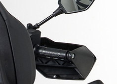
Электронный курок газа

Новая многофункциональная приборная LСD-панель
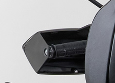
Новая форма рукояток для повышения комфорта управления мотовездеходом
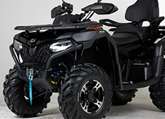
Яркий и стильный дизайн, унаследованный от прежней версии

EPS (электроусилитель рулевого управления) значительно снижает нагрузку на руки, демпфирует удары в руль во время езды по пересеченной местности, позволяет легко маневрировать на любых скоростях
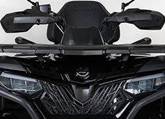
Вместительные передняя и задняя грузовые площадки
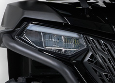
Отдельные ходовые огни заменены ближним светом
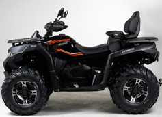
Новая форма рамы и подвески для снижения вибраций
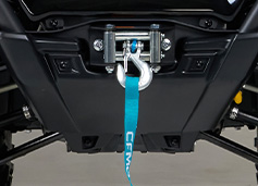
Лебедка с тяговым усилием 1361 кгс (3000 lbs). Разъем пульта управления лебедкой стал влагозащищённым.
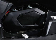
Современный одноцилиндровый 4-клапанный двигатель повышенной мощности в 45 л. с.
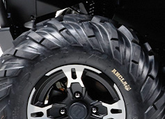
Надежная и эффективная 4-суппортная тормозная система
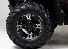
12-дюймовые легкосплавные колесные диски с 26-дюймовыми шинами с развитым грунтозацепом
Рекомендуемые аксессуары для CFMOTO CFORCE 600 EPS
В кредит от
79 руб/мес
9 500₽
В кредит от
245 руб/мес
29 400₽
В кредит от
161 руб/мес
19 370₽
В кредит от
209 руб/мес
25 110₽
В кредит от
70 руб/мес
8 400₽
CFORCE 600 S EPS оснащен 580-кубовым, 4-клапанным, инжекторным двигателем жидкостного охлаждения, уже хорошо проверенным на двухместной модели CFORCE 600 EPS.
Также в одноместной версии в базовой комплектации есть электроусилитель рулевого управления (EPS), что значительно облегчает пилотирование техники, и езда становится невероятно комфортной!
За передачу мощности в 41 л.с. и высокого крутящего момента отвечает надежный канадский вариатор CVTech с обгонной муфтой, обеспечивающей дополнительное торможение двигателем на крутых спусках. Приемистый мотор и специально откалиброванный для российских условий эксплуатации вариатор обеспечивают новому CFORCE 600 S EPS быстрый и плавный набор скорости – он способен преодолеть 50 м всего за 4,5 секунды!
Новый CFORCE 600 S EPS отлично показал себя в тестовых испытаниях, приняв участие в ПЯТИ любительских соревнованиях на квадроциклах, выигрывая у техники именитых мировых брендов. Это отличная альтернатива японским производителям, для тех, кто соскучился по достойным и доступным одноместным моделям!
На CFORCE 600 S EPS допускается движение по дорогам общего пользования.
Дополнительные преимущества:
- EPS (Электроусилитель рулевого управления)
- Регулируемая подвеска
- Новый дизайн багажных платформ
- Лебедка с тяговым усилием 1361 кгс
- Цифровая панель приборов с 12 показателями
- Встроенные Bluetooth с индикацией входящего вызова.
- Светодиодные световые приборы (LED)
- Усовершенствованная тормозная система
- Выбор режимов работы трансмиссии
- Эргономичное сиденье водителя
- Защита рук водителя
Еще одна новинка 2023 года от CFMOTO — квадроцикл CFORCE 600 Advanced EPS. На сегодня это самый продвинутый представитель линейки 600-кубовых квадроциклов CFMOTO. Благодаря изменениям, двигатель стал мощнее, а квадроцикл технологичнее и современнее. Электронный курок газа, кованый поршень, выбор режимов работы двигателя нового CFORCE 600 Advanced EPS позволяют демонстрировать превосходные ездовые характеристики в зависимости от условий эксплуатации.
Увеличенная мощность и возможность выбора режимов работы двигателя новинки позволят не только покорять более серьезное бездорожье, но и выполнять работы на загородном участке или стать верным спутником на охоте или рыбалке в дебрях лесов и на болотах.
На CFORCE 600 Advanced EPS допускается выезд на дороги общего пользования.
Преимущества
- Новый вид оптики: отдельные ходовые огни заменены ближним светом;
- Яркий и стильный дизайн, унаследованный от прежней версии;
- Электроусилитель рулевого управления EPS;
- Канадский вариатор CVTech;
- Новая многофункциональная приборная LСD-панель;
- Лебедка с тяговым усилием 1361 кгс (3000 LBS);
- Электронный курок газа делает управление подачей топлива более точным;
- Изменена форма рамы для снижения вибраций;
- Новые рукоятки для повышения комфорта управления мотовездеходом;
- Двухместное сиденье, оборудованное съемной пассажирской секцией и ручками для пассажира;
- Надежная и эффективная 4-суппортная тормозная система;
- Передняя и задняя багажные площадки имеют облицовки из высокопрочного пластика.
Силовой агрегат квадроцила CFMOTO CFORCE 600 Advanced EPS
| Марка | 191S-B |
|---|---|
| Тип двигателя | Одноцилиндровый, жидкостного охлаждения, четырехтактный, 4-клапанный, с одним распределительным валом верхнего расположения (SOHC) |
| Охлаждение | Жидкостное |
| Рабочий объем | 580 куб. см |
| Мощность | 33 кВт (45 л.с.) при 6500 об/мин |
| Макс. крутящий момент | 51 Н∙м при 6000 об/мин |
| Топливная система | Система впрыска топлива BOSCH (EFI) |
| Зажигание | Электронная система зажигания, с модулем управления (ECU) |
| Стартер | Электрический |
| Трансмиссия | Вариатор +КПП (L-H-N-R-P). Режимы работы 2WD/4WD/4WD c блокировкой дифференциала |
Размеры CFMOTO CFORCE 600 Advanced EPS
| Длина/Ширина/Высота | 2235/1180/1390 мм |
|---|---|
| Колесная база | 1480 мм |
| Дорожный просвет | 270 мм |
| Сухая масса | 386 кг |
| Высота посадочных мест | 830 мм |
Шасси CFMOTO CFORCE 600 Advanced EPS
| Тип передней подвески | Независимая, на двойных поперечных А-образных рычагах с гидравлическими амортизаторами |
|---|---|
| Ход передней подвески | 160 мм |
| Тип задней подвески | Независимая, на двойных поперечных Н-образных рычагах с гидравлическими амортизаторами, стабилизатором поперечной устойчивости |
| Ход задней подвески | 210 мм |
| Тормозная система | Гидравлическая, двухконтурная |
| Передний тормоз | Двухдисковый, колёсный |
| Задний тормоз | Двухдисковый, колёсный |
| Парковочный тормоз | Механическая блокировка трансмиссии/гидравлический дисковый |
| Колеса передние/задние | 26*9-12/26*11-12, бескамерные с развитым грунтозацепом |
| Колесные диски | 12″/12″ легкосплавные |
Характеристики CFMOTO CFORCE 600 Advanced EPS
| Количество мест | 2 |
|---|---|
| Максимальная конструктивная скорость | 95 км/ч |
| Емкость топливного бака | 18 л |
| Радиус разворота | 3700 мм |
| Максимальная нагрузка на грузовые решетки Пер. / Зад. | 20/40 |
| Базовая комплектация |
|
Фото квадроцикла CFMOTO CFORCE 600 Advanced EPS