- Manuals
- Brands
- Shihlin electric Manuals
- Inverter
- SC3 Series
- User manual
-
Contents
-
Table of Contents
-
Bookmarks
Quick Links
Shihlin Electric General Inverters
SC3 Series
User Manual
SC3-021-0.2K~2.2K
SC3-023-0.2K~3.7K
SC3-043-0.4K~5.5K
DELIVERY AND INSPECTION
1
2
3
4
5
6
7
Related Manuals for Shihlin electric SC3 Series
Summary of Contents for Shihlin electric SC3 Series
-
Page 1: Table Of Contents
Shihlin Electric General Inverters SC3 Series User Manual SC3-021-0.2K~2.2K SC3-023-0.2K~3.7K SC3-043-0.4K~5.5K MANUAL GUIDE DELIVERY AND INSPECTION INVERTER INTRODUCTION PRIMARY OPERATION PARAMETER DESCRIPTION INSPECTION AND MAINTENANCE APPENDIX…
-
Page 3: Manual Guide
1. MANUAL GUIDE 1.1 Safety instructions Thank you for choosing Shihlin inverters of SC3 series. This instruction introduces how to correctly use this inverter. Before using this inverter, always carefully read this User Manual and moreover, please understand the safety instructions.
-
Page 4: Inverter Introduction
Definitions of terminologies 1.2 Contents User Manual …………………………….- 1 — 1. MANUAL GUIDE …………………………..1 1.1 Safety instructions …………………………1 1.2 Contents …………………………….2 1.3 Definitions of terminologies ……………………….. 7 2. DELIVERY CHECK …………………………..8 2.1 Nameplate instruction ………………………… 8 2.2 Type instruction …………………………..
-
Page 5: Parameter Description
Safety Instructions 4.2 Operation modes of the inverter …………………….. 33 4.2.1 The flow chart for switching the operation mode ………………. 34 4.2.2 The flow chart for switching the working mode ………………34 4.2.3 The operation flow charts for monitoring mode ………………35 4.2.4 Operation flow charts for frequency setting mode ……………..
-
Page 6
Definitions of terminologies 5.2.5 Starting frequency ……………………….67 5.2.6 Load pattern selection V/F ……………………. 68 5.2.7 JOG operation ……………………….. 70 5.2.8 Output frequency filter time ……………………70 5.2.9 Frequency jump……………………….71 5.2.10 The second function ……………………..72 5.2.11 Middle frequency, output voltage of middle frequency V/F …………..73 5.2.12 S pattern time ………………………. -
Page 7: Inspection And Maintenance
Safety Instructions 5.9.1 PID function selection……………………..138 5.9.2 PID parameter group ……………………..138 5.10 Application parameter group 10 ……………………143 5.10.1 DC injection brake ……………………..146 5.10.2 Zero-speed/zero-servo control………………….147 5.10.3 DC injection brake before start ………………….147 5.10.4 Restart mode selection …………………….. 148 5.10.5 Remote setting function selection ………………….
-
Page 8
Definitions of terminologies 7.4.2 DU06 operation panel ……………………..190 7.4.3 DU08 operation panel ……………………..191 7.4.4 DU10operation panel ……………………..193 7.4.5 CBL: Data transmission line (coordinated with the operation panel) ……….194 7.5 Appendix 6 European Specification Compatibility Description…………..196 8. -
Page 9: Definitions Of Terminologies
Safety Instructions 1.3 Definitions of terminologies Output frequency, target frequency, steady output frequency The actual output current frequency of the inverter is called “output frequency.” The frequency set by user (viaoperation panel, multi-speed terminals, voltage signal, and current signal or …
-
Page 10: Delivery Check
Input voltage :043:440V 3-PHASE 023:220V 3-PHASE 021:220V 1-PHASE Product line 2.3 Order code description Example: Specification Description Order SC3-043-1.5K SC3 series 440V 1.5kW inverter SNKSC30431R5K SC3-043-3.7K SC3series 440V 3.7kW inverter SNKSC30433R7K SC3-043-5.5K SC3series 440V 5.5kW inverter SNKSC30435R5K MANUAL GUIDE 8…
-
Page 11: Inverter Introduction
Nameplate instruction 3. INVERTER INTRODUCTION 3.1 Electric specification 3.1.1 440V series three-phase Frame SC3-043-□□□K-□□ 0.75 Model Ratedoutput capacity (kVA) Rated output current(A) Applicable motor capacity (HP) Output Applicable motor capacity (kW) 0.75 Overload current rating 150% 60seconds 200% 1 second inverse time characteristics Carrier frequency (kHz) 1~15kHz Maximum output voltage…
-
Page 12: Vseries Three-Phase
General specification 3.1.2 220Vseries three-phase Frame SC3-023-□□□K-□□ 0.75 Model Rated output capacity (kVA) Rated output current(A) 17.5 Applicable motor capacity (HP) 0.25 Output Applicable motor capacity (kW) 0.75 Overload current rating 150% 60seconds 200% 1 second inverse time characteristics Carrier frequency (kHz) 1~15kHz Maximum output voltage Three-phase 200-240V…
-
Page 13: Vseries Single-Phase
Nameplate instruction 3.1.3 220Vseries single-phase Frame SC3-021-□□□K-□□ 0.75 Model Rated output capacity (kVA) Rated output current(A) Applicable motor capacity (HP) 0.25 Output Applicable motor capacity (kW) 0.75 Overload current rating 150% 60seconds 200% 1 second inverse time characteristics Carrier frequency (kHz) 1~15kHz Maximum output voltage Three-phase 200-240V…
-
Page 14: General Specification
General specification 3.2 General specification Control method SVPWM control, V/F control,General magnetic vector control Output frequency range 0~650.00Hz The frequency is set within 100Hz, the resolution is 0.01Hz. Digital setting Frequency The frequency is set more than100Hz, the resolution is 0.1Hz. setting DC 0~5V or 4~20mA signal, 11 bit.
-
Page 15: Appearance And Dimensions
Appearance and dimensions 3.3 Appearance and dimensions 3.3.1 Frame A Unit:mm Model SC3-021-0.2K SC3-021-0.4K SC3-021-0.75K SC3-023-0.2K SC3-023-0.4K 26.5 SC3-023-0.75K SC3-023-1.5K SC3-043-0.4K SC3-043-0.75K SC3-043-1.5K INVERTER INTRODUCTION 13…
-
Page 16: Frame B
Appearance and dimensions 3.3.2 Frame B Unit: mm Model SC3-021-1.5K SC3-021-2.2K SC3-023-2.2K SC3-023-3.7K 26.5 SC3-043-2.2K SC3-043-3.7K SC3-043-5.5K INVERTER INTRODUCTION 14…
-
Page 17: Name Of Each Component
Peripheral devices 3.4 Name of each component 3.4.1 Frame A/B Fan cover Manufacture Nameplate Lower cover Top cover Operator connector Control circuit stickers Mounting holes INVERTER INTRODUCTION 15…
-
Page 18: Installation And Wiring
Peripheral devices 3.5 Installation and wiring 3.5.1 Transportation Take the pedestal when carrying and don’t only take the cover or any part of the inverter, otherwise it may drop down. 3.5.2 Storage Keep this product in the packaging before installation and when not in use. To change the frequency that meets the manufacturer’s warranty and maintenance conditions, please pay attention to the following regarding storage: 1.
-
Page 19
Peripheral devices Please comply with installation conditions shown below to ensure enough ventilation space and wiring space for inverter cooling: Arrangement of single or paralleling inverter: Size Frame A Frame B Air direction Arrangement of multiple inverters: Inverter Inverter Inverter… -
Page 20: Emc Installation Instructions
Peripheral devices 3.5.4 EMC installation instructions Just as other electrical and electronic equipments, an inverter is the source of electromagnetic interference and an electromagnetic receiver when working with a power system. The amount of electromagnetic interference and noise is determined by the working principles of an inverter. In order to guarantee the inverter working reliably in the electromagnetic environment, it must have a certain ability of anti-electromagnetic interference in design.
-
Page 21: Peripheral Devices
Peripheral devices 3.6 Peripheral devices 3.6.1 System Wire Arrangement Power Please follow the specific Power power supply requirement supply shown in this manual. FUSE/ NFB There may be an inrush current during power up. Fuse/NFB Please refer to 3.6.2 and Magnetic contactor select the correct fuse /NFB.
-
Page 22: No-Fuse Switch And Magnetic Contactor
Peripheral devices 3.6.2 No-fuse switch and magnetic contactor Applicable no-fuse switch Applicable electromagnetic Power source Inverter model Motor capacity (NFB/MCCB) type contactor (MC) type capacity (Shihlin Electric) (Shihlin Electric) SC3-043-0.4K 440V 0.5HP 1 kVA BM30SN3P3A S-P11 SC3-043-0.75K 440V 1HP 2kVA…
-
Page 23: Brake Resistor
Peripheral devices 3.6.3 Brake Resistor Inverter model Brake resistor specification SC3-043-2.2K 300W 160Ω SC3-043-3.7K 500W 120Ω SC3-043-5.5K 1000W 75Ω SC3-023-2.2K 300W 60Ω SC3-023-3.7K 400W 40Ω SC3-021-1.5K 300W 60Ω SC3-021-2.2K 300W 60Ω Note: 1. For brake resistor whose built-in brake unit offers model options, the capacity of the regenerative brake is based on the condition that the regenerative brake duty is 10% (when braking lasts for 5 seconds, the machine has to be stopped for another 45 seconds must be stopped for heat dissipation).
-
Page 24: Terminal Wire Arrangement
Terminal wire arrangement 3.7 Terminal wire arrangement ON:Defaut Screw OFF:Remove Screw SINK SOURCE Note 1:SC3-043-0.4K~1.5K,SC3-023-0.2~1.5K,SC3-021-0.2~0.75K have not +/P and PR terminals. Note 2:Full range of built-in RFI filter to suppress electromagnetic interference, but if you want to meet CE standard, please refer to the instructions in the operating manual for installation.
-
Page 25: Main Circuit Terminals
Terminal wire arrangement 3.7.1 Main circuit Terminals Description Terminal symbol Description R/L1-S/L2-T/L3 Connect to the commercial power supply U/T1-V/T2-W/T3 Connect to the three-phase squirrel-cage motor. (+/P)-PR Connect to the brake resistor. (B framework built-in brake unit) ground terminal Note: 1.Frame A don’t have and the terminals +/P and PR.
-
Page 26: Main Circuit Wiring And Terminal Specification
Terminal wire arrangement 3.7.2 Main circuit wiring and terminal specification Recommended wiring specification Recommended wiring Terminal Tightening Inverter specification (AWG) screw torque model Grounding Grounding specifications (Kgf.cm) R,S,T U,V,W R,S,T U,V,W Cable Cable SC3-021-0.2K SC3-023-0.2K SC3-043-0.4K SC3-021-0.4K SC3-023-0.4K SC3-043-0.75K SC3-021-0.75K SC3-023-0.75K SC3-043-1.5K SC3-023-1.5K…
-
Page 27: Ground
Poor 3.7.4 RFI filter The inverters of SC3 series are equipped with built-in RFI filters. These filters are effective in reducing electromagnetic interference, but if in line with CE standard, please refer to Section 3.5.4 for installation and wiring. Frame A/B…
-
Page 28: Control Circuit
Terminal wire arrangement 3.7.5 Control circuit Control terminal name Terminal type Terminal name Function instructions Terminal specifications Input impedance: 4.7 kΩ There are totally 4 multi-function control Digital signal Action current: 5mA(when 24VDC) terminals, which can switch mode of input Voltage range: 10~28VDC SINK/SOURCE.
-
Page 29
Terminal wire arrangement Control logic (SINK/SOURCE) change The multi-function control terminal of SC3 series inverter can select the sink input approach or the source input approach via the toggle switch. The diagram is as follows No matter what kind of multi-function control terminal is, all of its outside wire arrangement can be considered as a simple switch. -
Page 30
Terminal wire arrangement Inverter Inverter Source Input: the multi-function control Source Input: the multi-function control terminal is connected directly with open-emitter PLC terminal is shorted directly with PC Inverter Source Input: the multi-function control terminal is connected with open-emitter PLC and external power supply … -
Page 31
Terminal wire arrangement Please do use blade terminals with insulation sleeve. Blade terminals commercially available: Crimping tool Blade terminals Cable gauge (mm²) L (mm) d1 (mm) d2 (mm) Manufacturer product model number AI 0,25-6 WH 10.5 AI 0,5-6 WH Phoenix 0.75 AI 0,75-6 GY… -
Page 32
Terminal wire arrangement Toggle switch Switch Switch Explanation Remarks number state SINK/SOURCE Switch the input models “STF、STR、M0、M1” Input 0~10V voltage signal into terminal 3-5 AVI/ACI Input 4~20mA current signal into terminal 3-5 Note: 1. The state with “*” is the default state of switch. 2. -
Page 33: Replacement Procedure Of Fan
Replacement procedure of fan 3.8 Replacement procedure of fan 3.8.1 Frame A/B 1. Press the hooks on both side of the fan to remove the 2. Disconnect the power terminal, and then remove the fan. (As shown below.) fan. (As shown below.) INVERTER INTRODUCTION 31…
-
Page 34: Primary Operation
Component name of parameter unit (PU301) 4. PRIMARY OPERATION 4.1 Component name of operation panel Operation parts Name Content PU: ON to indicate the PU operation mode, flickers in the Operation mode indicator H1~H5 operation mode. Operation panel MON: ON to indicate the monitoring mode. status indicator Run status indicator The light is on when running.
-
Page 35: Operation Modes Of The Inverter
Basic operation procedures for different modes 4.2 Operation modes of the inverter The operation modes are related to the reference source of the target frequency and the signal source of the motor starting. The Shihlin SC3 inverter has a total of ten kinds of operation modes, namely, “PU mode ”, “JOG mode ”, “external mode…
-
Page 36: The Flow Chart For Switching The Operation Mode
Basic operation procedures for different modes 4.2.1 The flow chart for switching the operation mode Note: 1.In “PU mode”, operation panel screen displays , and the indicating lamp will light up. 2.In “external mode,” operation panel screen displays 3. In “combined mode 1, 2, 3, 4, or 5”, the indicating lamp will glitter on the operation panel screen.
-
Page 37: The Operation Flow Charts For Monitoring Mode
Basic operation procedures for different modes 4.2.3 The operation flow charts for monitoring mode ●Take PU mode for example: Note: 1.In the “monitoring output frequency mode”, indicating lamp will light up, and the screen will display the current output frequency. 2.
-
Page 38: Operation Flow Charts For Parameter Setting Mode
Basic operation procedures for different modes 4.2.5 Operation flow charts for parameter setting mode Note: Neither Indicating lamp will light up under the parameter setting mode. Please Use to write the parameter. 4.2.6 Operation flow charts of HELP model, using SC3-TYPE operation panel Note: 1.Browsing the alarm record, display screen shows the recent four groups of alarm codes.
-
Page 39: Basic Operation Procedures For Different Modes
Basic operation procedures for different modes 4.3 Basic operation procedures for different modes 4.3.1 Basic operation procedures for PU mode (00-16(P.79)=0 or 1) Step Description • Change the operation mode to PU mode, and indicating lamp will light up. Note: 1. When 00-16(P.79) =0, the inverter will first go into the external mode after the power is switched on or the inverter is reset.
-
Page 40: Basic Operation Procedures For Jog Mode (00-16(P.79)=0 Or 1)
Basic operation procedures for different modes 4.3.3 Basic operation procedures for JOG mode (00-16(P.79)=0 or 1) Step Description • Change the operation mode to the JOG mode and indicating lamp will light up. At this point, the screen will display Note: For selecting and switching the operation mode, please refer to Section4.2.
-
Page 41: Basic Operation Procedures For Combined Mode 2 (00-16(P.79)=5)
Basic operation procedures for different modes 4.3.6 Basic operation procedures for combined mode 2 (00-16(P.79)=5) Step Description • In Combined Mode 2, indicating lamp will light up. Note: For selecting and switching the operation mode, please refer to Section4.2. • The target frequency is set by the external terminals (the default priority is from high to low): •…
-
Page 42: Basic Operation Procedures For Combined Mode 3 (00-16(P.79)=6)
Basic operation procedures for different modes 4.3.7 Basic operation procedures for combined mode 3 (00-16(P.79)=6) Step Description • In Combined Mode 3, indicating lamp will light up. Note: For selecting and switching the operation mode, please refer to Section4.2. • The target frequency is determined by communication: •When RL, RM, RH and REX of multi-speed stage levels are “on”, the target frequency is determined by combination of multi-speed stage levels(Please refer to 04-00~04-02/P.4~P.6, 03-00~03-01/P.83~P.84,03-03~03-04/P.80~P.81。) •When external JOG is “on”, the target frequency is determined by 01-13(P.15).
-
Page 43: Basic Operation Procedures For Combined Mode 5 (00-16(P.79)=8)
Basic operation procedures for different modes 4.3.9 Basic operation procedures for combined mode 5 (00-16(P.79)=8) Step Description • In Combined Mode 5, indicating lamp will light up. Note: For selecting and switching the operation mode, please refer to Section4.2. •The target frequency of the inverter is set byoperation panel: •…
-
Page 44: Operation
Operation 4.4 Operation 4.4.1 Pre-operation checks and preparation Before starting the operation, the following shall be examined: 1. Check if the wiring is correct. Check especially the ac motor driver output terminals (U/T1, V/T2, W/T3), which cannot be connected to the power. Confirm that grounding terminal ( ) is well grounded.
-
Page 45: Trial Run
Operation 4.4.3 Trial run Check cables and abnormalities before the trial run. After power on, the inverter is in the external mode. After power on, make sure the operating screen is normal, the indicating lamp power is on. 2. Connect a switch between STF and SD or STR and SD. 3.
-
Page 46: Parameter Description
System parameter group00 5. PARAMETER DESCRIPTION 5.1 System parameter group00 Parameter Factory Group Name Setting Range Page Number Value 00-00 P.90 The inverter model Read 00-01 P.188 Firmware version Read 0: Non-function 1: Alarm history clear (P.996=1) 2: Inverter reset (P.997=1) P.996~…
-
Page 47
System parameter group00 Parameter Factory Group Name Setting Range Page Number Value 0: Output voltage (V) 1: DC bus voltage (V) 2: Temperature rising accumulation rate of inverter (%) 3: Target pressure of the constant pressure system (%) 4: Feedback pressure of the constant pressure system (%) 5: Operation frequency (Hz) 6: Electronic thermal accumulation rate (%) 7: Reserved. -
Page 48
System parameter group00 Parameter Factory Group Name Setting Range Page Number Value 00-11 P.72 Carrier frequency 1~15 5 kHz 0: None Soft-PWM operation 1: When 00-11(P.72)< 5, Soft-PWM is valid (only apply to V/F control ) Soft-PWM carrier 00-12 P.31 2: When P.72>9, Inverter module’s temperature is operation selection exorbitant, carrier will automatically lower, after module’s… -
Page 49: Inverter Information
System parameter group00 5.1.1 Inverter information Inquire the inverter model, control board firmware version, and the connected expansion card, etc. Factory Parameter Name Setting Range Content Value 00-00 The inverter model Read P.90 00-01 Firmware version Read The inverter control board firmware version P.188 The inverter model …
-
Page 50: Parameter Restoration
System parameter group00 5.1.2 Parameter restoration Restore the parameters to the default values. Factory Parameter Name Setting Range Content Value No function. Alarm history clear (P.996=1) Inverter reset (P.997=1) 00-02 Parameter restoration Restoring all parameters to default values (P.998=1) Restoring some parameters to default values1(P.999=1) Restoring some parameters to default values 2 (P.999=2) Restoring some parameters to default values 3(P.999=3)
-
Page 51
System parameter group00 Group Name 3-5 current/voltage input corresponding to the percentage of plus 02-61 P.141 or minus 05-00 P.301 Motor parameter auto-tuning function selection 05-01 P.302 Motor rated power 05-02 P.303 Motor poles 05-03 P.304 Motor rated voltage 05-04 P.305 Motor rated frequency 05-05… -
Page 52: Parameter Protection
System parameter group00 5.1.3 Parameter protection Whether to enable the writing to various parameters or not can be selected. Use this function to prevent parameter values from being rewritten by disoperation. Factory Parameter Name Setting Range Content Value Parameters can be written only when the motor stops. Selection of 00-03 Parameters cannot be written.
-
Page 53
System parameter group00 The parameters cannot be written. (00-03=“1”) Exception The parameters below can be written. Group Name Group Name 00-03 P.77 Selection of parameters write protection 00-16 P.79 Operation mode selection During operation, the parameters below can also be written.(00-03=“2”) … -
Page 54
System parameter group00 Note: Please keep the password properly. Bring the inverter to the factory for decryption if the password is forgotten. PARAMETER DESCRIPTION 52… -
Page 55: Monitoring Function
System parameter group00 5.1.4 Monitoring function The item to be displayed on the operation panel can be selected. Factory Parameter Name Setting Range Content Value When the inverter starts, the operation panel enters the monitoring mode automatically, and the screen displays the output frequency.
-
Page 56: Speed Display
System parameter group00 Display Operation panel monitoringselection Display the current target pressure and feedback pressure of the constant pressure system(00-06=“3”). At this point, the screen display shows two sections. A decimal point is used to separate the boundaries. What is on the left is the target pressure of the constant pressure system and what is on the right is the feedback pressure 0 3 0 of the constant pressure system.
-
Page 57: The Setting Frequency Selection Of Rotary Knob On The Operating Keyboard
System parameter group00 5.1.6 The Setting Frequency Selection of Rotary Knob on the Operating Keyboard According the different setting values determing the frequency values which are set by the keyboard. Factory Parameter Name Setting Range Content Value The frequency set by frequency inverter itself shuttle knob is XXX0 effective The frequency set by the knob of the manipulator is…
-
Page 58: Stop Operation Selection
System parameter group00 The higher Carrier frequency, the inverter rated current will decline, which was to prevent the inverter to overheat and extend the life of IGBT, so that protection measures are necessary. The carrier frequency is 8kHz or below, rated current of a inverter is 100%, as the carrier frequency increase, rating current will decline, and accelerate product heat to protect the inverter.
-
Page 59: Forward/Reverse Rotation Prevention Selection
System parameter group00 The output of the inverter will follow the acceleration/deceleration curve to decelerate until stop after the stop signal is accepted. Deceleration time (the time is set by P.8) linear braking time Operation signal Setting Button function selection to stop the operation.(00-14=“1”) …
-
Page 60: Operation Mode Selection
System parameter group00 5.1.10 Operation mode selection Select the operation mode of the inverter, and determine the source of start signal and target frequency. Factory Parameter Name Setting Range Content Value “PU mode”, “external mode” and “Jog mode” are interchangeable.
-
Page 61: Hz Switch Selection
System parameter group00 General magnetic vector control of induction motor: The voltage boost, the frequency changes when compensation motor load increases. Note: 1. Motor capacity shall be same level or lower level with inverter capacity. 2. When making automatic measurement, such as allowing the motor rotation, please set the P.301 = 1 (dynamic measurement), the load and the motor must be made out completely.
-
Page 62: Parameter Mode Setting
System parameter group00 5.1.13 Parameter mode setting Select “order number” or “parameter group” to display parameters. Factory Parameter Name Setting Range Content Value Parameter is displayed as “group mode” 00-25 Parameter mode P.990 setting Parameter is displayed as “conventional P mode” Parameter mode setting Display “Parameter group”…
-
Page 63: Basic Parameter Group01
Basic parameter group 01 5.2 Basic parameter group01 Parameter Factory Group Name Setting Range Page Number Value 01-00 Maximum frequency 0.00~01-02(P.18)Hz 120.00Hz 01-01 Minimum frequency 0~120.00Hz 0.00Hz High-speed maximum 01-02 P.18 01-00(P.1)~650.00Hz 120.00Hz frequency 50Hz system setting: 0~650.00Hz 50.00Hz 01-03 Base frequency 60Hz system setting: 0~650.00Hz 60.00Hz…
-
Page 64
Basic parameter group 01 Parameter Factory Group Name Setting Range Page Number Value 0~650.00Hz 01-19 P.94 Frequency jump 2B 99999 99999: invalid 0~650.00Hz 01-20 P.95 Frequency jump 3A 99999 99999: invalid 0~650.00Hz 01-21 P.96 Frequency jump 3B 99999 99999: invalid The second acceleration 0~360.00s/0~3600.0s 01-22… -
Page 65: Limiting The Output Frequency
Basic parameter group 01 5.2.1 Limiting the output frequency Output frequency can be limited. Clamp the output frequency at the upper and lower limits. Factory Parameter Name Setting Range Content Value 01-00 0.00~ Maximum frequency 120.00Hz 01-02(P.18)Hz 01-01 Minimum frequency Output minimum frequency 0.00Hz 0~120.00Hz…
-
Page 66: Base Frequency, Base Frequencyvoltage
Basic parameter group 01 5.2.2 Base frequency, base frequencyvoltage Use this function to adjust the inverter outputs (voltage, frequency) to match with the motor rating. Factory Parameter Name Setting Range Content Value 01-03 50.00Hz 50Hz system (00-24=1) Base frequency 0.00~650.00Hz 60.00Hz 60Hzsystem (00-24=0)
-
Page 67: Acceleration/Deceleration Time Setting
Basic parameter group 01 5.2.3 Acceleration/deceleration time setting Use this function to set motor acceleration/deceleration time. Factory Parameter Name Setting Range Content Value Linear acceleration /deceleration curve S pattern acceleration /deceleration curve 1 (Note 1) 01-05 Acceleration/deceleration P.29 curve selection S pattern acceleration /deceleration curve 2 (Note 2) S pattern acceleration /deceleration curve 3 (Note 3) 01-06…
-
Page 68
Basic parameter group 01 01-03(P.3) 01-06(P.7) Time S pattern acceleration /deceleration curve 2(01-05=2) An acceleration slope is formed by the combination of 01-06 and 01-09. A deceleration slope is formed by the combination of 01-07 and 01-09. When the target frequency varies, the acceleration curve has an S-shape ascending according to the “acceleration slope”. -
Page 69: Starting Frequency
Basic parameter group 01 5.2.4 Torque boost For an inverter controlled by V/F mode, when the motor starts up, the starting torque is usually inadequate since the output voltage of the inverter is inadequate. In this case, the output voltage can be elevated by properly setting the torque boost (01-10), and thus a better starting torque can be acquired.
-
Page 70
Basic parameter group 01 5.2.6 Load pattern selection Optimal output characteristics for application or load characteristics can be selected when in V/F control. Factory Parameter Name Setting Range Content Value Applicable to constant torque loads (convey belt, etc.) Applicable to variable torque loads (fans and pumps, etc.) 01-12 Load pattern selection 2、3… -
Page 71
Basic parameter group 01 01-12=4 01-12=5 P.19 P. 19 P.169 P.167 P.165 P.163 Output frequency P.99 P.98=3.0 P.3 Output frequency (Hz) P.168 P.98 P.162 P.164 P.166 Whether it is high startup torque or descending torque, they are due to When P.14 = 5, the value of A is 7.1% (Note 2). the set values (Note 1). -
Page 72: Jog Operation
Basic parameter group 01 5.2.7 JOG operation The frequency and acceleration/deceleration time for JOG operation can be set. JOG operation can be used for conveyor positioning, test run, etc. Factory Parameter Name Setting Range Content Value 01-13 JOG frequency 5.00Hz 0~650.00Hz P.15…
-
Page 73: Frequency Jump
Basic parameter group 01 5.2.9 Frequency jump When it is desired to avoid resonance attributable to the natural frequency of a mechanical system, these parametersallow resonant frequencies to be jumped. Factory Parameter Name Setting Range Content Value 01-16 0~650.00Hz Frequency jump 1A 99999 P.91…
-
Page 74: The Second Function
Basic parameter group 01 5.2.10 The second function It is appropriate for the parameters when the RT signal is ON. Factory Parameter Name Setting Range Content Value 0~360.00s/ 01-08=0/ 01-22 The second 0~3600.0s 01-08=1 99999 P.44 acceleration time 99999 Not selected.
-
Page 75
Basic parameter group 01 5.2.11 Middle frequency, output voltage of middle frequency Parameters can be set when using a special motor, especially adjusting the motor torque. Factory Parameter Name Setting Range Content Value 01-26 Middle frequency 1 3.00Hz 0~650.00Hz P.98 01-27 Output voltage 1 of… -
Page 76: S Pattern Time
Basic parameter group 01 5.2.12 S pattern time It is used to set the acceleration time of S pattern acceleration/deceleration. Factory Parameter Name Setting Range Content Value S pattern time at the 01-36 0~25.00s/ 01-08=0/ beginning of 0.20s P.255 0~250.0s 01-08=1 acceleration…
-
Page 77
Basic parameter group 01 Example: when the parameters are initial value (60 Hz system), the actual acceleration time from 0Hz to 60Hz in accordance with S pattern acceleration/deceleration curve 3 is as follows: P.256 Acceleration / deceleration reference frequency (P.20) Fre2 P.256/2 P.255… -
Page 78: Analog Input And Output Parameter Group 02
Digital input/ output parameter group03 5.3 Analog input and output parameter group 02 Parameter Factory Group Name Setting Range Page Number Value 02-06 P.185 Proportion linkage gain 0~100% 0: No auxiliary frequency function is available. 2: operation frequency = basic frequency + auxiliary frequency (given by the 3-5 terminal) 02-07 P.240…
-
Page 79: Proportion Linkage Gain
Digital input/ output parameter group03 5.3.1 Proportion linkage gain The function is used to multiply the setting frequency by the external analog input terminal. When many inverters run proportionally, the reference frequency from the master inverter to the slave inverter can be fine tuned effectively with the function.
-
Page 80: Auxiliary Frequency
Digital input/ output parameter group03 5.3.2 Auxiliary frequency It can flexibly implement fine tuning of frequency and frequency synthesis to meet different control requirements of different scenarios. Factory Parameter Name Setting Range Content Value No auxiliary frequency function is available. Operation frequency = basic frequency + auxiliary frequency (given by the 3-5 terminal) 02-07…
-
Page 81: Selection And Handling Of Input Terminal 3-5
Digital input/ output parameter group03 5.3.3 Selection and handling of input terminal 3-5 Selects the signal specifications, frequency compensation function, etc, via input terminal 3-5. Factory Parameter Name Setting Range Content Value 02-10 3~5 filter time 31ms 0~2000ms P.60 The effective range of signal sampling is 4~20mA.
-
Page 82
Digital input/ output parameter group03 P.17 = 0 P.17 = 1,2 P.39 P.39 Input voltage signal Input current signal across terminal 3-5 across terminal 3-5 20mA Setting Handling of input terminal 3-5 The parameters above define the relationship between analog input voltage and the setting value what analog input represents. -
Page 83
Digital input/ output parameter group03 parameters P.141 set in a way, a total of two, it’s the meaning of each said as follows: P.141= 0: parameters p. 196 value is positive 1: the parameters of p. 196 has a negative value 0: parameters p. -
Page 84
Digital input/ output parameter group03 Example 3: This example is also frequently used by the industry. The comprehensive usage for all domain of the potentiometer setup elevates the flexibility. Max output parameter setting: frequency 60Hz P.39 = 60Hz max operation frequency P.17 = 1 Voltage signal selection P.141 = 0 P.198=0V, P.199=10V 3-5… -
Page 85
Digital input/ output parameter group03 Example 6: This example is an extension of Example 6. The wide application of this example offers the users good flexibility. Max output frequency 60Hz Parameter setting: P.39 = 60Hz max operation frequency P.17 = 1 Voltage signal selection P.141 = 0 P.198=0V, P.199=10V 3-5 Terminal min/max positive voltage… -
Page 86
Digital input/ output parameter group03 Max output frequency 60Hz Forward direction 30Hz Parameter setting: P.39 = 60Hz Max operation frequency P.17 = 1 Voltage signal selection 30Hz P.141 = 1 P.198=0V, P.199=10V 3-5 Terminal min/max positive voltage Reverse direction P.196=100%, P.197=0% The percentage of 3-5 Terminal 60Hz min/max positive voltage… -
Page 87: Output Current According To The Benchmark
Digital input/ output parameter group03 Note: 1. In the mode of «external» or «mixed mode 2» or «mixed mode 4», if the AU «on» and 02-01 = 1, the target frequency of frequency converter, is decided by 3-5 terminal signal. 2.
-
Page 88: Digital Input/Output Parameter Group03
Digital input/ output parameter group03 Note: parameters 02-52 factory value determined by the model. 5.4 Digital input/output parameter group03 Parameter Factory Group Name Setting Range Page Number Value 0: STF(the inverter runs forward) 1: STR(the inverter runs reverse) 2: RL(Multi-speed low speed) 3: RM(Multi-speed medium speed) 4: RH(multi-speed high speed) 5:Reserved…
-
Page 89
Digital input/ output parameter group03 when the alarm goes off.) Parameter Factory Group Name Setting Range Page Number Value 35: MPO (in “external mode” the manually operation cycle mode is chosen.) 36: TRI(triangle wave function is chosen) 37: Reserved 38: Reserved 39: STF/STR +STOP (The motor has a reverse rotation when the RUN signal is on. -
Page 90
Digital input/ output parameter group03 Parameter Factory Group Name Setting Range Page Number Value Multi-function terminal digital 03-14 P.87 0~15 input negative/positive logic Multi-function terminal digital 03-15 P.88 0~3 output negative/positive logic 03-16 P.120 Output signal delay time 0~3600.0s 0.0s Digital input terminal filter 03-17 P.157… -
Page 91: Function Selection Of Digital Input
Digital input/ output parameter group03 5.4.1 Function selection of digital input Use the following parameters to select or change the digital input terminal functions. Any function from 0 to 45 can be selected by each terminal (Note 1). Factory Parameter Name Setting Range…
-
Page 92
Digital input/ output parameter group03 Factory Parameter Name Setting Range Content Value RES_E (external reset become valid only when the alarm goes off.) MPO (in “external mode” the manually operation cycle mode is chosen.) TRI(triangle wave function is chosen) Reserved Reserved 03-00 STF/STR +STOP (The motor has a reverse rotation when… -
Page 93
Digital input/ output parameter group03 Operating Instructions STF(P.8X=0) Stop STR(P.8X=1) Run Forward Run Reverse Stop Two-wire control mode 2: Operating Instrnctions RUN(P.8X=28) Stop STF/STR(P.8X=29) Stop Run Forward Run Reverse Three-wire control mode 1 (with self-maintenance function): K0 is for the STOP function that is normally close. When it is open, the inverter will stop. -
Page 94: Function Selection Of Digital Output
Digital input/ output parameter group03 STR is “on”, the operation will be suspended. When STR is “off”, the operation will be continued (continues from the suspended section).For details, please refer to 04-15, 04-27~04-42, 04-16~04-18 and 04-19~04-26. In the external mode, the manual operation cycle mode is selected when MPO is “on”. For details on parameter, …
-
Page 95: Terminal Logic Selection
Digital input/ output parameter group03 5.4.3 Terminal logic selection The function is bits-setting, if the bit shows 1, it means that the action of multi-function digital input terminal is negative logic; otherwise, it means that the action is positive logic. Factory Parameter Name…
-
Page 96: Output Signal Delay
Digital input/ output parameter group03 5.4.4 Output signal delay It is used for digital output terminal signal delay and confirmation. The delay time is confirmation time to prevent some uncertain interference. Factory Parameter Name Setting Range Content Value 03-16 Output signal delay 0.0s 0~3600.0s…
-
Page 97: Digital Input Terminal Power Enable
Digital input/ output parameter group03 5.4.6 Digital input terminal power enable Selects power enables on the digital input terminal, whether the inverter operates immediately. Factory Parameter Name Setting Range Content Value Digital input terminal power disable. 03-18 Digital input terminal P.158 power enable Digital input terminal power enable.
-
Page 98: Zero Current Detection
Digital input/ output parameter group03 Setting Output frequency detection for forward / reverse rotation If 03-21=30 and 03-22=20, then it will send out FUsignals when the forward rotation output frequency exceeds 30Hz or when the reverse rotation output frequency exceeds 20Hz. If 03-21=30 and 03-22=99999 (factory default), then it will send out FU signals when the forward or reverse …
-
Page 99: Multi-Speed Parameter Group04
Multi-speed parameter group 04 5.5 Multi-speed parameter group04 Parameter Factory Group Name Setting Range Page Number Value 04-00 Speed1(high speed) 0~650.00Hz 60.00Hz 04-01 Speed2(medium speed) 0~650.00Hz 30.00Hz 04-02 Speed3(low speed) 0~650.00Hz 10.00Hz 0~650.00Hz 04-03 P.24 Speed4 99999 99999: Function invalid 04-04 P.25 Speed5…
-
Page 100
Multi-speed parameter group04 Parameter Factory Group Name Setting Range Page Number Value Programmed operation mode 04-27 P.101 0~6000.0s 0.0s speed 1 operating time Programmed operation mode 04-28 P.102 0~6000.0s 0.0s speed 2 operating time Programmed operation mode 04-29 P.103 0~6000.0s 0.0s speed3 operating time Programmed operation mode… -
Page 101: Speeds
Multi-speed parameter group 04 5.5.1 16 speeds With the combination of digital input terminal RL, RM, RH and REX, selects speed operation (the most are 16 speeds in total) Factory Parameter Name Setting Range Content Value 04-00 Speed1(high speed) 60.00Hz 0~650.00Hz 04-01…
-
Page 102
Multi-speed parameter group04 Speed Speed Speed (High speed) speed1 Speed Speed Speed Speed speed (Medium Speed speed) Speed 2 Speed Speed (Low speed) Speed 3 Speed Speed Provided that the parameter set values of 04-03~04-06 and 04-07~04-14 are all 99999, the target frequency will … -
Page 103: Programmed Operation Mode
Multi-speed parameter group 04 5.5.2 Programmed operation mode The application of this parameter can be used as the operation process control for general small machinery, food processing machinery and washing equipment, which can replace some traditional relays, switches, timer and other control circuit, etc.
-
Page 104
Multi-speed parameter group04 Factory Parameter Name Setting Range Content Value Programmed operation 04-31 mode speed 5 operating 0.0s 0~6000.0s P.105 time Programmed operation 04-32 mode speed 6 operating 0.0s 0~6000.0s P.106 time Programmed operation 04-33 mode speed 7 operating 0.0s 0~6000.0s P.107 time… -
Page 105
Multi-speed parameter group 04 frequency P.111 P.112 P.113 P.114 P.116 P.118 P.117 P.115 P.118 P.101 P.102 pause P.103 P.104 P.105 P.106 P.107 P.108 The run direction is set in binary form (8-bit), and then translated to decimal form and stored in 04-16. “1” means run forward, and “0”… -
Page 106
Multi-speed parameter group04 Frequency P.135 P.132 P.133 P.131 P.134 P.132 P.131 „„ Note: 1. The inverter can run eight levels of speed in the procedure, and the frequency is determined by 04-19~04-26. 2. For the setting of 04-15~04-18 and 04-27~04-42, it is valid for programmed operation mode only, not for manual operation cycle mode;… -
Page 107: Motor Parameter Group05
Protection parameter group06 5.6 Motor parameter group05 Parameter Factory Group Name Setting Range Page Number Value 0: Parameter auto-tuning function with no motor 1: Induction motor parameter auto-tuning Motor parameter measuring the running motor 05-00 P.301 auto-tuning function 2: Induction motor parameter auto-tuning selection measuring the stopped motor 3: Induction motor online auto-tuning function…
-
Page 108: Motor Parameter Auto-Tuning Function Selection
Protection parameter group06 5.6.1 Motor parameter auto-tuning function selection Via accurate motor parameter auto-tuning function, realizes motor high-performance vector control. Factory Parameter Name Setting Range Content Value Parameter auto-tuning function with no motor Induction motor parameter auto-tuning measuring the Motor parameter running motor 05-00…
-
Page 109
Protection parameter group06 Confirm the wiring (Please refer to 3.7 Terminal wire arrangement) Set motor parameter Set motor parameter (05-01~05-06) (05-01 ~ 05-06) 05-00 1, 2 Press the forward/reverse rotation key Restore display and start to measure, the operation after panel will display “TUN”. -
Page 110: Motor Parameter
Protection parameter group06 5.6.2 Motor parameter The standard parameters of the adaptable motor have been configured inside the inverter. It is still necessary to perform motor auto-tuning or modify the default values based on actual conditions. Factory Parameter Name Setting Range Content Value…
-
Page 111: Protection Parameter Group06
Protection parameter group06 5.7 Protection parameter group06 Parameter Factory Group Name Setting Range Page Number Value Electronic thermal relay According 06-00 0~500.00A capacity to type Stall prevention operation 06-01 P.22 0~250.0% 150.0% level 0~200.0% Compensation factor at 06-02 P.23 99999 99999: Stall prevention operation level is the level reduction setting value of 06-01(P.22).
-
Page 112
Protection parameter group06 Parameter Factory Group Name Setting Range Page Number Value 2: The fan will be turned on when the temperature of the heat sink is higher than 60℃. When it is lower than 40℃, the fan will be turned off. 06-12 P.245 Cooling fan operation… -
Page 113: Electronic Thermal Relay Capacity
Protection parameter group06 5.7.1 Electronic thermal relay capacity The “electronic thermal relay” uses the program of the inverter to simulate a thermal relay for preventing the motor from overheating. Factory Parameter Name Setting Range Content Value 06-00 Electronic thermal According 0~500.00A relay capacity…
-
Page 114: Regenerative Brake
Protection parameter group06 When the motor starts or target frequency is adjusted (increasing) under a heavy load, the motor speed is often unable to follow the output frequency closely. If the motor speed is lower than the output frequency, the output current will increase to improve the output torque.
-
Page 115: Over Torque Detection
Protection parameter group06 5.7.4 Over torque detection The output current detection function can be used for purposes such asover torque detection. Factory Parameter Name Setting Range Content Value No over torque detection. 06-08 Over torque detection 0.0% P.155 level 0.1~200% Over torque detection.
-
Page 116: Cooling Fan Operation
Protection parameter group06 5.7.5 Cooling fan operation Control the run/stop condition of the fan and the alarm output mode. Factory Parameter Name Setting Range Content Value The fan will be turned on when running. The fan will be turned off 30 seconds after inverter stops. Turning on the power will turn on the fan.
-
Page 117: Time Record Function
Protection parameter group06 by 06-19. If choose the startup of floor drain current detection, detection to the output of short-circuit current, and by more than 50% of the rated current, short circuit current converter to stop output, called GF different police. If in frequency converter operation, the output of short-circuit current is detected, the 06-19 and short-circuit …
-
Page 118
Protection parameter group06 Factory Parameter Name Setting Range Content Value When 06-42(P.290) =7, 06-43(P.291) corresponds to the frequency when the alarm goes off once before. When 06-42(P.290) =8, 06-43(P.291) corresponds to the current when thealarm goes off once before. When 06-42(P.290) =9, 06-43(P.291) corresponds to the output voltage when thealarm goes off once before. -
Page 119: Communication Parameter Group 07
Communication parameter group07 5.8 Communication parameter group 07 Parameter Factory Group Name Setting Range Number Value Communication 0: Modbus protocol 07-00 P.33 protocol selection 1: Shihlin protocol Inverter station 07-01 P.36 0~254 number 0: Baud rate:4800bps 1: Baud rate:9600bps Serial 2: Baud rate:19200bps communication 07-02…
-
Page 120: Shihlin Protocol And Modbus Protocol
Communication parameter group07 5.8.1 Shihlin protocol and Modbus protocol Parameter settings and monitoring are possible by using the inverter RS-485 terminals and the position machine link communication. Factory Parameter Name Setting Range Content Value 07-00 Communication Modbus protocol P.33 protocol selection Shihlin protocol The number of inverters is practically determined by the…
-
Page 121
I nver t er 1 I nver t er 2 I nver t er n SC3 series inverters support Shihlin communication protocol and MODBUS communication protocol. Shihlin communication protocol Automatically switch the position machine and the inverter to ASCII codes (hexadecimal) for communication. -
Page 122
Communication parameter group07 The above steps concerning communication actions and communication data format are explained below: Operation Frequency Parameter Inverter Parameters Action content Monitoring reference write-in write-in reset Read-out Use the position machine’s user ① procedure to send communication request to the inverter. ②… -
Page 123
Communication parameter group07 *1) Control code Signal ASCIICode Content Signal ASCIICode Content NULL(Empty) Acknowledge(No data error) Start of Text(Data begin) Line Feed(Change line) End of Text( Carriage Return Data end Enquiry(Communication request) Negative Acknowledge(Data errors) *2) Set the waiting time from 0 to 15 with a 10ms unit. Example: 5 —>50ms. *3) End symbol (CR, LF codes) When carrying out data communication from the position machine to the inverter, CR and LF codes at the end of the text are automatically set according to method of the position machine. -
Page 124
Communication parameter group07 Step 2: After receiving and processing the data without error, the inverter will send a reply to the position machine in Format C: Inverter station number H30 H30 Example 2. The position machine sends a stop rotation reference to the inverter: Step 1: Use the position machine to send a FA reference in Format A: Inverter station Reference… -
Page 125
Communication parameter group07 H30 H30 H31 H37 H37 H30 H36 H31 Example 4. Change the content of 04-07(P.142) to 50 (the original factory setting is 0). Step 1 to 2: Omitted (Same as Step 1 to 2 of Example 3); Step 3: The position machine requests the inverter to write 50 in 04-07(P.142) in Format A: Inverter station number Reference code… -
Page 126
Communication parameter group07 MODBUS communication protocol Message format MODBUS serial transmission can be divided into two types:ASCII (American Standard Code for Information Interchange) and RTU (Remote Terminal Unit). Response time for INV Single PC(Master) Query Msssage Response Message INV(Slave)… -
Page 127
Communication parameter group07 Message Content Function name Function code Function description Read multiple Read slave machine’s continuous register content. registers ②Function message Write single register Write data into slave machine’s single register. Function diagnosis Function diagnosis (only for communication calibration) Write multiple Write data into slave machine’s multiple registers. -
Page 128
Communication parameter group07 Regular response Read-out Mode Start Address*1) Function*2) data number Read-out data*6) Check Stop ASCII 2char 2char 2char 4char …2N×8bit 2char 0D 0A >=10ms 8bit 8bit 1byte 2byte …N×8bit 2byte >=10ms Message Content *1)Address Set up the address for the to-be delivered message; 0 for invalid. *2)Function code *3)Starting address Set up the address of the register for reading the message. -
Page 129
Communication parameter group07 Message Content *1)Address Set up the address for the to-be delivered message. *2)Function code *3)Starting address Set up the starting address of the register to be engaged in the write-in function. *4)Number of register Set up the number of register for reading. Maximum number: 20. *5) Amount of data The range should be 2 ~ 24. -
Page 130
Communication parameter group07 The list of error codes: Source Code Meaning Remarks Set up function codes that cannot be handled by the equipment in the query Invalid function code message sent by the main equipment. Function codes that are not H03, H06, H08 and H10 (temporarily). -
Page 131
Communication parameter group07 Mode Starting Address Function Number of data read Read-out data Check Stop ASCII H30 H31 H30 H33 H30 H32 H31 H37 H37 H30 H37 H33 0D 0A >=10ms B6 50 >=10ms Because the decimal form of H1770 is 6000 and the unit of 04-07(P.142) is 0.01, 04-07(P.142) is 60 (6000 x 0.01 = 60). Example 3. -
Page 132
Communication parameter group07 The list of communication references The following references and data are set for carrying out assorted operation control and monitoring. Shihlin Modbus protocol Modbus Item reference Data content and function description reference address code code Operation mode H0000: communication mode;… -
Page 133
Communication parameter group07 Shihlin Modbus protocol Modbus Item reference Data content and function description reference address code code H5A5A H1104 H5566 H5959 H1103 H9966 For details, please refer to H06/ Parameter delete H9696 the parameter restoration status table. H1106 H99AA H9A9A H1105 H55AA… -
Page 134
Communication parameter group07 Shihlin Modbus protocol Modbus Item reference Data content and function description reference address code code P mode: H0000: P.0~P.99; H0001: P.100~P.199; H0002: P.200~P.299; H0003: P.300~P.399; Page H0004: P.400~P.499; change for Parameter group mode: parameter H0064: 00-00~00-99; Read reading H0065: 01-00~01-99;… -
Page 135
Communication parameter group07 Parameter restoration condition table Communication User Data Parameter Table 1 Table 2 Other P Error Parameter P registered content Operation (Note2) (Note2) parameters codes (Note 1) parameter H5A5A 00-02=4(P.999=1) H5566 00-02=5(P.999=2) H5959 00-02=6(P.999=3) H9966 00-02=3(P.998 H9696 Communication 999 1 H99AA Communication 999 2… -
Page 136
Communication parameter group07 PARAMETER DESCRIPTION 134… -
Page 137: Writing Selection Of Communication Eeprom
Communication parameter group07 5.8.2 Writing Selection of Communication EEPROM Set it when you need to change the parameter Parameter Name Name Name Content Writing selection of parameter Write the of EEPROM , RAM through 07-11 communication communication. P.34 EEPROM parameter communication.
-
Page 138
Communication parameter group07 PARAMETER DESCRIPTION 136… -
Page 139: Pid Parameter Group08
PID parameter group08 5.9 PID parameter group08 Parameter Factory Group Name Setting Range Page Number Value 0: PID function non-selected 08-00 P.170 PID function selection 1: Parameter 08-03(P.225) sets target value. Take the input of terminal 3-5 as target source 0: Negative feedback control.
-
Page 140: Pid Function Selection
PID parameter group08 5.9.1 PID function selection Process control such as flow rate, air volume or pressure is possible on the inverter. A feedback system can be configured and PID control can be performed using the digital input signal or parameter setting value as the set point, and the digital input signal as the feedback value.
-
Page 141
PID parameter group08 Factory Setting Parameter Name Content Value Range Free stop 08-09 Exception handling Decelerate and stop P.177 mode Continue to run when the alarm goes off 08-10 Sleep detects 0~ 0.0% P.178 deviation 100.0% 08-11 Sleep detects 1.0s 0~255.0s P.179 duration time… -
Page 142
PID parameter group08 Example 1: When the 0~7V feedback signal is given by terminal 3-5: When 08-01=0 (negative feedback control),08-18 = 0.1 / 7 * 100.0 = 1.4 08-19 = 5 / 7 * 100.0 = 71.4 When 08-01=1 (positive feedback control),08-18 = (7 — 0.1) / 7 * 100.0 = 98.6 08-19 = (7- 5) / 7 * 100.0 = 28.6 By setting 08-18 and 08-19 as the above calculated value, and then setting 08-00 at 1, 02-00 at 4(terminal 3-5) or 08-00 at 3, 02-02 at 4(terminal 3-5), the revised range is 0~7V. -
Page 143
PID parameter group08 =P.172 contravariance U/T1 R/L1 e(t) V/T2 limit filter =P.173 P.182 S/L2 W/T3 T/L3 =P.174 Output Target PID module frequency value Feedback value feedback quantity convertor When the output frequency reaches the value of 01-03 * 08-14, the feedback value will be less than the product of … -
Page 144
PID parameter group08 the target feel-back value Revival level feedback P.179 below actually P.179 Minishing the Output output frequency frequency gradually Outage level Revival Outage process proccess PID gain simple setting: After changing target, response is slow —Increase P-gain (K =08-04) response is quick but unstable —Decrease P-gain (K… -
Page 145: Application Parameter Group 10
Application parameter group10 5.10 Application parameter group 10 Parameter Factory Group Name Setting Range Page Number Value DC injection brake operation 10-00 P.10 0~120.00Hz 3.00Hz frequency DC injection brake operation 10-01 P.11 0~60.0s 0.5s time DC injection brake operation 10-02 P.12 0~30.0% 4.0%…
-
Page 146
Application parameter group Parameter Factory Group Name Setting Range Page Number Value 0: Retry is invalid. 1: Over-voltage occurs; the inverter will perform the retry function. 2: Over-current occurs; the inverter will perform 10-12 P.65 Retry selection the retry function. 3: Over-voltage or over-current occurs;… -
Page 147
Application parameter group10 function 1:Reciprocating mechanical function effectively 10-56 P.227 Forward limit of time 0~3600.0s 0.0s 10-57 P.228 0~3600.0s 0.0s Reverse time limited PARAMETER DESCRIPTION 145… -
Page 148: Dc Injection Brake
Application parameter group 5.10.1 DC injection brake Timing to stop or braking torque can be adjusted by applying DC voltage to the motor to prevent the motor shaft to turn at the time of stopping motor. Factory Parameter Name Setting Range Content Value…
-
Page 149: Zero-Speed/Zero-Servo Control
Application parameter group10 5.10.2 Zero-speed/zero-servo control Zero-speed/ zero-servo function selection Factory Parameter Name Setting Range Content Value There is no output at zero-speed. 10-03 Zero-speed control P.151 function selection DC voltage breaking 10-04 Voltage at zero-speed 5.0% 0~30.0% P.152 control Zero-speed control Setting…
-
Page 150: Restart Mode Selection
Application parameter group 5.10.4 Restart mode selection Select the best start mode according to the different load. Factory Parameter Name Setting Range Content Value No frequency search. Reserved 10-08 Decrease voltage mode Restart mode selection P.150 Power on once. Start each time.
-
Page 151: Remote Setting Function Selection
Application parameter group10 Instantaneous (power failure) time Power supply (R/L1,S/L2,T/L3) Motor speed N (r/min) Inverter output frequency f (Hz) Inverter output voltage E (v) Coasting time Restart cushion time P.57setting P.58 setting * The output shut off timing differs according to the load condtion 5.10.5 Remote setting function selection If the operation box is located away from the control box, one can use contact signals to perform variable-speed …
-
Page 152
Application parameter group Whether the remote setting function is valid and whether the frequency setting storage function in the remote setting mode is used or not are determined by 10-11. Set 10-11=1~3 (valid remote setting function), the function of terminal RM, RH and RL will be changed to acceleration (RH), deceleration (RM) and clear (RH).See the following figure: Inverter Forward rotation… -
Page 153: Retry Selection
Application parameter group10 5.10.6 Retry selection This function allows the inverter to reset itself and restart at fault indication. The retry generating protective functions can be also selected. Factory Parameter Name Setting Range Content Value Retry is invalid. Over-voltage occurs; the inverter will perform the retry function.
-
Page 154: The Dead Time Of Positive And Reverse Rotation
Application parameter group 5.10.7 The dead time of positive and reverse rotation Set the waiting or holding time after the output frequency outputs to 0Hz when the positive and reverse rotation is switching. Factory Parameter Name Setting Range Content Value Without the function.
-
Page 155
Application parameter group10 Note: 1. This function is valid only in the V/F mode(00-21=“0”). 2. After selecting the energy-saving running mode, the deceleration time may be longer than the setting value. In addition, the properties of the regular torque load will produce abnormal voltage more easily. Please slightly prolong the deceleration time. -
Page 156
Application parameter group Backlash compensation function Output frequency P.232 P.230 P.13 time P.231 P.233 Note: The setting of the backlash compensation will only prolong the acceleration/deceleration time during the period of interruption. Acceleration and deceleration interrupt waiting function(10-18=“2”) When 10-18=2, start acceleration and deceleration interrupt waiting function. When accelerating to the frequency set by 10-19, wait for the time set by 10-20 and then accelerate to the target. -
Page 157
Application parameter group10 5.10.10 Triangular wave function The triangular wave operation, which oscillates the frequency at a constant cycle, is available. Factory Parameter Name Setting Range Content Value 0: None. 10-23 Triangular wave External TRI is turned on,triangular wave function will be P.234 function selection valid. -
Page 158: Reciprocating Engine Function
Application parameter group 5.10.11 Reciprocating engine function The inverter contains control function for switching between the commercial power supply operation andinverter operations. Therefore, interlock operation of the magnetic contactor for switching can be easily performed bysimply inputting start, stop, and automatic switching selection signals. Factory Parameter Name…
-
Page 159
Application parameter group10 When K3 (K4) is closed,press K1 and rotate forward (reverse) to K4(K3),close then rotate forward (reverse) again. Press K2 to shut down the system. To prevent damage on travel switch, a time limitation for forward and reverse rotate was added in the system. Both … -
Page 160: Speed And Torque Control Parameter Group 11
Speed and torque control parameter group11 5.11 Speed and torque control parameter group 11 Parameter Factory Group Name Setting Range Page Number Value 11-00 P.320 Slip compensation gain 0~200% Torque compensation filter 11-01 P.321 0~32 coefficients First set of current filter cutoff 11-02 P.322 0~30.00Hz…
-
Page 161: Special Adjustment Parameter Group13
Measurement of main circuit voltages, currents and powers 5.12 Special adjustment parameter group13 Parameter Factory Group Name Setting Range Page Number Value 13-00 P.89 Slip compensation coefficient 0~10 High frequency vibration 13-03 P.286 0~15 inhibition factor 5.12.1 Slip compensation This parameter can be used to set compensation frequency and reduce the slip to close the setting speed when …
-
Page 162: User Parameter Group 15
Measurement of main circuit voltages, currents and powers 5.13 User parameter Group 15 Parameter Factory Group Name Setting Range Page Number Value 15-00 P.900 User registration parameter 1 99999 15-01 P.901 User registration parameter 2 99999 15-02 P.902 User registration parameter 3 99999 15-03 P.903…
-
Page 163: User Registration Parameters
Measurement of main circuit voltages, currents and powers 5.13.1 User registration parameters User parameter groups register parameters of numberwhich users do not need to be restored the factory values. Factory Parameter Name Setting Range Content Value 15-00 User registration parameter 1 99999 P.900 15-01…
-
Page 164: Inspection And Maintenance
Measurement of main circuit voltages, currents and powers 6. INSPECTION AND MAINTENANCE 6.1 Inspection item 6.1.1 Daily inspection item The inverter is a unit mainly consisting of semiconductor devices. Daily inspection must be performed to prevent any fault from occurring due to the adverse effects of the operating environment, such as temperature, humidity, dust, dirt and vibration, changes in the parts with time, service life, and other factors.
-
Page 165: Cleaning
Measurement of main circuit voltages, currents and powers 6.1.3 Cleaning Always run the inverter in a clean status. Use a soft brush to remove thedust andsundry on the fan blade, fan cover, and radiator, keeping the inverter in good heat dissipation.
-
Page 166: Measurement Of Main Circuit Voltages, Currents And Powers
Measurement of main circuit voltages, currents and powers 6.2 Measurement of main circuit voltages, currents and powers 6.2.1 Selection of instruments for measurement Since the voltages and currents on the inverter input sides and output sides include harmonics, measurement data …
-
Page 167: Measurement Of Power
Measurement of main circuit voltages, currents and powers produces a large error and may indicate an extremely smaller value than the actual value. The value monitored on the operation panelis accurate if the output frequency varies, and it is recommended to monitor values (provide analog output) using the operation panel.
-
Page 168: Appendix
Appendix 1 Parameter table 7. APPENDIX 7.1 Appendix 1 Parameter table Parameter Factory Group Name Setting Range Page Number Value 0.2~0.75K types: 0~30.0% 6.0% 01-10 Torque boost 1.5K~3.7K types: 0~30.0% 4.0% 5.5K types: 0~30.0% 3.0% 01-00 Maximum frequency 0.00~01-02(P.18)Hz 120HZ 01-01 Minimum frequency 0~120.00Hz…
-
Page 169
Appendix 1 Parameter table Parameter Factory Group Name Setting Range Page Number Value 0: Effective range of signal sampling is 4~20mA. P.17 02-20 3-5 signal selection 1: Effective range of signal sampling is 0~10V. 2: Effective range of signal sampling is 0~5V. High-speed maximum P.18 01-02… -
Page 170
Appendix 1 Parameter table Parameter Factory Group Name Setting Range Page Number Value Communication protocol 0: Modbus protocol P.33 07-00 selection 1: Shihlin protocol 0: Write parameters in communication mode, Writing selection of write into RAM and EEPROM P.34 07-11 communication 1: Write parameters in communication mode, EEPROM… -
Page 171
Appendix 1 Parameter table Parameter Factory Group Name Setting Range Page Number Value P.58 10-10 Restart cushion time 0~60.0s 5.0s XXX0:The frequency set by frequency inverter itself shuttle knob is effective XXX1: Thefrequencyset by the knob of the manipulator is effective. X0XX:After changing the frequency, automatic storage after 30 s Operating keyboard knob… -
Page 172
Appendix 1 Parameter table Parameter Factory Group Name Setting Range Page Number Value Stall prevention operation 50Hz system: 0~650.00Hz 50.00Hz P.66 06-03 reduction starting 60Hz system: 0~650.00Hz 60.00Hz frequency 0: Retry is invalid. Number of retries at alarm 1~10: The setting value of 10-13(P.67) is P.67 10-13 occurrence… -
Page 173
Appendix 1 Parameter table Parameter Factory Group Name Setting Range Page Number Value 0: “PU mode”, “external mode” and “Jog mode” are interchangeable. 1: “PU mode” and “JOG mode” are interchangeable. 2: “External mode” only 3: “Communication mode” only P.79 00-16 Operation mode selection 4: “Combined mode 1”… -
Page 174
Appendix 1 Parameter table Parameter Factory Group Name Setting Range Page Number Value 28: RUN(the inverter runs forward) 29: STF/STR(it is used with RUN, when STF/ STR is “on”, the inverter runs reverse;when STF/STR is “off”, the inverter runs forward) 30: RES(external reset function) 31: STOP(it can be used as a three-wire mode with the RUN signal or the STF-STR terminal) -
Page 175
Appendix 1 Parameter table Parameter Factory Group Name Setting Range Page Number Value 9: Reserved 10: Reserved 11: OMD1(zero current detection) 12: OL2 (Over torque alarm output) P.85 03-11 A-C function selection 13~16: Reserved 17: RY(the accomplishmentofinverter running preparation) 18: Maintenance alarm detection Multi-functionterminaldigital P.87 03-14… -
Page 176
Appendix 1 Parameter table Parameter Factory Group Name Setting Range Page Number Value 0: The minimum increment of run time is 1 minute. P.100 04-15 Minute/second selection 1: The minimum increment of run time is 1 second. Programmed operation P.101 04-27 mode speed 1 operating 0~6000.0s… -
Page 177
Appendix 1 Parameter table Parameter Factory Group Name Setting Range Page Number Value Programmed operation P.111 04-35 mode speed 1 Acc/Dec 0~600.00s/0~6000.0s 0.00s time Programmed operation P.112 04-36 mode speed 2 Acc/Dec 0~600.00s/0~6000.0s 0.00s time Programmed operation P.113 04-37 mode speed 3 Acc/Dec 0~600.00s/0~6000.0s 0.00s time… -
Page 178
Appendix 1 Parameter table Parameter Factory Group Name Setting Range Page Number Value Programmed operation P.135 04-23 0~650.00Hz 0.00Hz mode speed 5 Programmed operation P.136 04-24 0~650.00Hz 0.00Hz mode speed 6 Programmed operation P.137 04-25 0~650.00Hz 0.00Hz mode speed 7 Programmed operation P.138 04-26… -
Page 179
Appendix 1 Parameter table Parameter Factory Group Name Setting Range Page Number Value P.155 06-08 Over torque detection level 0~200.0% 0.0% P.156 06-09 Over torque detection time 0~60.0s 1.0s Digital input terminal filter P.157 03-17 0~2000 time Digital input terminal power 0: Digital input terminal power disable P.158 03-18… -
Page 180
Appendix 1 Parameter table Parameter Factory Group Name Setting Range Page Number Value Output voltage 2 of middle P.163 01-29 0~100.0% 0.0% frequency 0~650.00Hz P.164 01-30 Middle frequency 3 99999 99999: Not selected Output voltage 3 of P.165 01-31 0~100.0% 0.0% middle frequency 0~650.00Hz… -
Page 181
Appendix 1 Parameter table Parameter Factory Group Name Setting Range Page Number Value P.185 02-06 Proportion linkage gain 0~100% P.188 00-01 Firmware version Read 0: The frequency parameter default valueis60Hz system. P.189 00-24 50Hz/60Hz switch selection 1: The frequency parameter default value is50Hz system. -
Page 182
Appendix 1 Parameter table Parameter Factory Group Name Setting Range Page Number Value P.233 10-22 Dwell time at deceleration 0~360.0s 0.5s 0: None. 1: External TRIis turned on, triangular wave Triangular wave function P.234 10-23 function will be valid. selection 2: The triangular wave function is effective at any given time. -
Page 183
Appendix 1 Parameter table Parameter Factory Group Name Setting Range Page Number Value S pattern time at the P.255 01-36 0~25.00s/0~250.0s 0.20s beginning of acceleration S pattern time at the end of 0~25.00s/0~250.0s P.256 01-37 99999 acceleration 99999: Not selected 0~25.00s/0~250.0s pattern time… -
Page 184
Appendix 1 Parameter table Parameter Factory Group Name Setting Range Page Number Value Accumulative motor power P.296 06-29 0~1439min 0min time (minutes) Accumulative motor power 06-30 0~9999day 0day P.297 time (days) 0: Induction motor V/F control Motor control mode P.300 00-21 1: reserved selection… -
Page 185
Appendix 1 Parameter table Parameter Factory Group Name Setting Range Page Number Value 15-00 P.900 User registration parameter 1 99999 15-01 P.901 User registration parameter 2 99999 15-02 P.902 User registration parameter 3 99999 15-03 P.903 User registration parameter 4 99999 15-04 P.904… -
Page 186: Appendix 2 Alarm Code List
Appendix 2 Alarm code list 7.2 Appendix 2 Alarm code list Code Screen display Cause Troubleshooting Under-voltage for power supply Provide a normal power supply The reset function “RES” is Shut off “RES” Ensure firm connection between the ERROR Bad connection between the operation panel main…
-
Page 187
Appendix 2 Alarm code list Code Screen display Cause Troubleshooting IGBT module thermal Avoid prolonged inverter operation when IGBT module accumulation relay operation overloaded. overload Check whether the set value of 06-00(P.9) is correct or not Electronic thermal relay operation (according to the externally Motor overload connected motor). -
Page 188
Appendix 2 Alarm code list Code Screen display Cause Troubleshooting Reduce the environment temperature The temperature of the inverter and improve the air condition. Overheated IGBT module is too high. Check whether the fan of the inverter module is running normally. Over-loaded motor Reduce motor load. -
Page 189: Appendix 3 Troubles And Solutions
Appendix 3 Troubles and solutions 7.3 Appendix 3 Troubles and solutions Troubles Check points •Check whether the power supply voltage between Terminals R/L1, S/L2 and T/L3 is normal. Main circuit •Check whether the Power light is on. •Check whether the wiring between the inverter and the motor is correct. •Check whether the load is too heavy.
-
Page 190: Appendix 4:Optional Accessories
Appendix 3 Troubles and solutions 7.4 Appendix 4:Optional accessories 7.4.1 PU301Parameter Unit PU301external view Description on the ordering code: Model Item Name Ordering Code PU301 LED Parameter Unit SNKPU301 outline dimensional drawing <Outline drawing> 4 × M3 10.95 92.8 114.7 26.9…
-
Page 191
Appendix 3 Troubles and solutions Surface mounting hole size figure 7.72 14.48 17.1 17.2 92.8 61.22 4- 3.5 Card buckle installation hole size chart < Car d buckl e i nst al l at i on: panel cut t i ng di m ensi on dr aw i ng > Cut out Ar ea plate… -
Page 192: Du06 Operation Panel
Appendix 3 Troubles and solutions 7.4.2 DU06 operation panel DU06 external view 42.4000 72.0000 Description on the ordering code: Model Item Name Ordering Code DU06 DU06operation panel SNKDU06 outline dimensional drawing < O ut l i ne dr aw i ng> 8.
-
Page 193: Du08 Operation Panel
Appendix 3 Troubles and solutions < Scr ew i nst al l at i on: panel cut t i ng di m ensi on dr aw i ng> 33.7 19.3 Cut out Ar ea 52.4 Snap-fit installation of DU06 <…
-
Page 194
Appendix 3 Troubles and solutions Outline drawing of DU08 <Outline dimensional drawing > 15.0 30.0 60.0 37.7 14.4 78.0 66.0 2-M3 < Surface mounting hole size figure>< Flange installation hole size chart (note)> 17.3 66.0 63.0 20.3 29.0 15.0 20.3 30.0 Note: the flange installation, installation of the base is not standard, need to purchase another, order code: SNKDUMH02… -
Page 195: Du10Operation Panel
Appendix 3 Troubles and solutions 7.4.4 DU10operation panel DU10external view Description on the ordering code: Model Item Name Ordering Code DU10 DU10operation panel SNKDU10 Outline drawing of DU10 > <Outline dimensional drawing 33. 4 36. 4 29. 8 13.
-
Page 196: Cbl: Data Transmission Line (Coordinated With The Operation Panel)
Appendix 3 Troubles and solutions 7.4.5 CBL: Data transmission line (coordinated with the operation panel) Model:SNKCBLxxGTN2 (xx expression 1R5, 3, 5, 10) Item No. Part No. L(mm) SNKCBL1R5GTN2 1500 SNKCBL3GTN2 3000 SNKCBL5GTN2 5000 SNKCBL10GTN2 10000 APPENDIX 194…
-
Page 197
Appendix 3 Troubles and solutions APPENDIX 195… -
Page 198: Appendix 6 European Specification Compatibility Description
Appendix 3 Troubles and solutions 7.5 Appendix 6 European Specification Compatibility Description This inverter qualifies the CE label. Specifications: Low Voltage Directive 2006/95/EC & Electromagnetic Compatibility Directive 2004/108/EC. 1. Electromagnetic compatibility command (EMC): (1). EMC compatibility description: For system integration, inverter is not a functionally independent device unit. It is usually a unit in the control box. It is combined with other devices to control a machine or equipment.
-
Page 199
Appendix 3 Troubles and solutions APPENDIX 197… -
Page 200
Appendix 3 Troubles and solutions APPENDIX 198… -
Page 201
Appendix 3 Troubles and solutions APPENDIX 199… -
Page 202: Revision Record
Appendix 3 Troubles and solutions 8. REVISION RECORD Published Date Edition of the Manual Revision Content 2015.07 V1.00 First Edition 1:Added: the European standard compatibility 2016.04 V1.01 2:Modified part of the parameter value and set the scope Amendment: 1. Modified the communication line in 7.4.4 specifications. 2.
Руководство пользователя

Руководство пользователя продукции Shihlin Electric
Центр загрузки Shihlin Electric для всех руководств. Пожалуйста, не стесняйтесь обращаться к нам, если произошла ошибка или требуется обслуживание.
- Загрузка файлов
-
Добро пожаловать в Шихлин Электрик
Компания Shihlin Electric была основана в 1955 году и занималась исследованиями, разработками, производством и маркетинговой интеграцией. Наше присутствие расширилось от Тайваня до мирового рынка
Рекомендация
Преимущество
-
Инновации — наша политика
Ведущий поставщик решений в области управления движением и энергосберегающих продуктов из Тайваня. Наше высочайшее…
Прочитайте больше
Преимущества:
• Монтаж на DIN-рейку
• RS-485
• Перегрузочная способность 150% Iном в теч. 60 сек.
Номинальная мощность:
0,4-2,2 кВт, 220 В, 1 ф.
0,75-5,5 кВт, 380 В, 3 ф.
Общая спецификация
| Наименование | Описание |
|---|---|
| Метод управления | Векторное управление, управление V/F |
| Диапазон выходной частоты | 0~650,00 Гц |
| Пусковой момент | 180 % 3 Гц, 200 % 5 Гц |
| Характеристики V/F | Кривая постоянного момента, кривая изменяемого момента, кривая по пяти точкам |
| Характеристики кривой ускорения / замедления |
Кривая линейного ускорения / замедления, кривая ускорения / замедления по S-рампе 1, 2 и 3 |
| Приводимый двигатель | Асинхронный двигатель (АД) |
| Защита от опрокидывания момента | Уровень защиты от опрокидывания можно настроить на 0~250% (06-01 (P.22)). Значение по умолчанию равно 200% |
| Настройка задания частоты | Настройка с помощью параметров, сигналом 0~5 В/10 В, сигналом -10~+10 В, сигналом 4~20 мА, настройка уровня каскада нескольких скоростей, настройка по каналу связи. |
| Функция передачи данных | Интерфейс связи RS-485, можно выбирать протокол передачи Shihlin/ Modbus, скорость передачи 115200 бит/с или выше. |
| Международная сертификация | CE, ТР ТС |
Основные клеммы
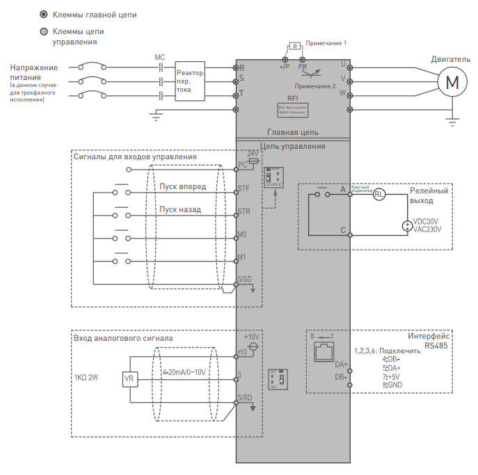
Описание клемм
| Название клеммы |
Описание клемм | Характеристики клемм |
|---|---|---|
| 5ТЕ , STR , МО , М1 | Всего имеется 4 универсальных клеммы управления, режим которых можно переключать между Приемник тока/Источник тока. | Входной импеданс: 4,7 кОм Активный ток: 5 мА (при напряжении 24 В пост, тока) Диапазон напряжений: 10 ~28 В пост. тока Максимальная частота: 1 кГц |
| 10 | +10,5 ± 0,5 В | Максимальный ток: 10 мА |
| 3 | 0~10 В/4~20 мА | Входной импеданс: 10 кОм |
| А , C | Клеммы универсального релейного выхода. Клеммы А-С нормально разомкнуты, С- это перекидной контакт |
Максимальное напряжение: 30 В пост. тока или 250 В пер. тока. Максимальный ток: активная нагрузки 5 А НР/3 А Н3 Индуктивная нагрузка: 2 А НР/1,2 А Н3 (соs Ø =0,4) |
| RJ45 , ВА+ , DB | RS-485 оптическая развязка Интерфейсы RJ45 и «DА+/DВ» — нельзя использовать одновременно. |
Наибольшая скорость: 115200 бит/сек. Наибольшее расстояние связи: 500 м |
| 5/SD | Общий провод для клемм STF, DTR, М0, М1, трех клемм для режима приемника тока (SINK) |
— |
| РС | Общий провод для клемм STF, STR, М0, М1 для режима источника тока (SOURCE) |
— |
1. Подключение силовых кабелей к ЧП:
| Символ клеммы | Описание |
|---|---|
| R/L1-S/L2-T/L3 U/T1-V/T2-W/T3 (+/P)-PR |
Подключение к сетевому источнику электропитания Подключение к трехфазному двигателю с короткозамкнутым ротором. Подключение к тормозному резистору (встроенный тормозной блок в габарите В) |
| Клемма заземления |
2. Начало работы:
Перед началом работы необходимо установить определённые параметры в частотном преобразователе. Для навигации по меню воспользуйтесь кнопкой ” MODE “, расположенной на лицевой панели частотного преобразователя. Для перемещения по меню и изменения параметров, воспользуйтесь «Встроенным потенциометром». Для того чтобы сохранить в памяти параметр, который вы изменили, воспользуйтесь кнопкой “SET”(Длительное нажатие).
Внимание!!! Изначально параметры настроены на отображения групп(в виде 00-00). Если Вам необходимо отображение параметров группы Р — установите 00-25 = 1.
3. Установка параметров для быстрого старта:
1) Выбор типа управления и задания частоты:
- При подачи питания на дисплее отобразиться значение «0.00».
- Для изменения типа управления нажмите 3 раза кнопку «MODE», пока не увидите на дисплее «OРnd» (запуск частотного преобразователя в работу и задание выходной частоты осуществляется с внешних клемм).
- Если повернуть ручку потенциометра вправо на одно деление, на дисплее отобразится «PU»(запуск частотного преобразователя в работу и задание выходной частоты осуществляется с панели оператора).
- Если повернуть ручку потенциометра вправо ещё на одно деление, на дисплее отобразится «JOG»(запуск частотного преобразователя в режиме толчковой работы и задание выходной частоты осуществляется с панели оператора).
- Параметр Р.79(00-16) отвечает за выбор типа управления частотным преобразователем.
- 0 Возможно быстро переключать режимы «Oрnd»(Работа с клемм),«PU»(работа с панели оператора) и «JOG»(Работа с панели оператора в режиме точковой работы).
- 1 Возможно быстро переключать режимы «PU»(работы с панели оператора) и «JOG»(Работа с панели оператора в режиме точковой работы).
- 2 Только режим «Oрnd»(Работа с клемм)
- 3 Работа в режиме «Передача данных» (Modbus или Shihlin protocol)
- 4 «Комбинированный режим 1» (Запуск с внешних клемм, задание частоты с потенциометра на панели оператора).
- 5 «Комбинированный режим 2» (Запуск с панели оператора, задание частоты с внешних клемм).
- 6 «Комбинированный режим 3» (Запуск с внешних клемм, задание частоты по протоколу связи).
- 7 «Комбинированный режим 4» (Запуск по протоколу связи, задание частоты с внешних клемм).
- 8 «Комбинированный режим 5» (Запуск с внешних клемм, задание частоты с пульта PU301).
2). Параметр задания базовой частоты Р.3(01-03) = 50. (Установите частоту, на которую рассчитан электродвигатель, согласно данным на шильде)
3). Параметр задания максимальной частоты Р.305(05-04) = 50 (Диапазон установки от 0 до 650Гц).
4) Время ускорения Р.7(01-06).
5) Время торможения Р.8(01-07).
4. Установка параметров мотора:
1). Параметр мощности мотора Р.302(05-01) (Устанавливаете номинальную мощность мотора, подключенного к частотному преобразователю).
2). Количество полюсов мотора Р.303(05-02) (Зависит от оборотов двигателя. 3000 = 2, 1500 = 4, 1000 = 6, 750 = 8).
3). Номинальный ток двигателя Р.306(05-05).
4). Напряжение питания мотора Р.304(05-03)
5. Подключение к внешним клеммам:
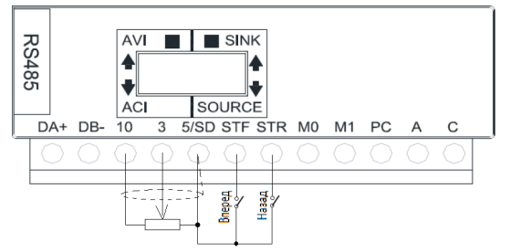
Подключение к внешним клеммам
- Для запуска частотного преобразователя в работу от внешних клемм необходимо замкнуть клеммы SD и STF(Прямое вращение) или STR(Обратное вращение).
- Для задания выходной частоты от внешних клемм, необходимо подключить подстроечный резистор (1-2кОм) на клеммы: 10(питание), 5(общая) и 3(клемма на которую будет подаваться управляющий сигнал).
- Для управления с внешних клемм не забудьте установить параметр выбора способа управления — Р.79(00-16)
Примечание:
В случае неудачного программирования функций частотного преобразователя не расстраивайтесь. Вы всегда можете вернуться к заводским параметрам. Для этого выберите параметр Р.997(00-02), установите его равным 1 и нажмите “SЕТ”
Для настройки других задач обратитесь к основной инструкции, приложенной к частотному преобразователю указанной в файле ниже.
Скачать полную документацию.
RU
Преобразователь частоты — это силовой электронный блок, который является посредником между системой управления и электродвигателем. Он обеспечивает питание для двигателя, защищает его и задаёт необходимый режим работы — разгон, торможение или постоянное изменение скорости.
Для примера возьмем шлифовальный станок, который часто можно встретить в промышленном цеху или в столярной мастерской. Для качественной работы станка движение должно осуществляться в двух направлениях, скорость вращения ленты — меняться плавно, а аварийная кнопка мгновенно отключать питание. Без преобразователя частоты тут точно не обойтись.

Рис.1 Внешний вид шлифовального станка.
Подключение силовых цепей
Все провода, подключаемые к частотному преобразователю, можно разделить на 2 группы: силовые и контрольные. Рассмотрим подключение силовых.
Три провода сетевого питания 380 В, 50 Гц — клеммы R, S, T + провод заземления PE. Нейтраль частотному преобразователю не нужна. Даже если она у вас есть, подключать не нужно. А вот провода питания можно подключать в любом порядке. При необходимости чередование фаз можно изменить в программе частотника.
Три провода питания двигателя — клеммы U, V, W + провод заземления PE. На выходе напряжение может меняться от 0 до 380 В, а частота от 0 до 500 Гц. В этом и кроется смысл работы частотного преобразователя — он позволяет изменять скорость двигателя от нуля до номинального значения и даже выше, если это позволяет механика.

Рис.2 Подключение силовых цепей
Подключение цепей управления
С контрольными проводами всё несколько сложнее. Тут нужно хорошо подумать, прежде чем подключать. На выбор целая россыпь дискретных и аналоговых входов и выходов. В документации производители чаще всего публикуют стандартную схему подключения с заводскими настройками, но для каждого механизма на деле нужна своя схема и индивидуальные настройки.

Рис.3 Подключение цепей управления
У нас задача не самая сложная. Для управления шлифовальной машиной достаточно кнопок «Пуск», «Стоп», переключателя «Вперед – Назад» и переменного резистора для изменения скорости вращения, его ещё называют потенциометром.
К дискретным входам DI подключаются сигналы, которые могут принимать одно из двух состояний — «вкл» и «выкл» или логический 0 и 1. В нашей схеме это кнопки «Пуск», «Стоп», переключатель направления и аварийный «грибок». Мы будем использовать кнопки без фиксации, которые уже установлены на станке.
К аналоговым входам AI подключаются сигналы с непрерывно меняющейся величиной тока 4…20 мА или напряжения 0…10 В. Это могут быть датчики, сигналы от контроллера или другого внешнего устройства. В нашем случае — это ручка потенциометра, которая обеспечивает плавную регулировку скорости.
Потенциометр или переменный резистор — это регулируемый делитель напряжения с тремя контактами.

Рис.4 Внешний вид потенциометра
На два крайних неподвижных контакта подаётся постоянное напряжение 10 В от частотного преобразователя, а средний подвижный контакт служит для снятия текущей величины напряжения, которая зависит от положения ручки. Если ручка повернута наполовину, значит и напряжение будет только половинное = 5 В. Преобразователь пересчитает напряжение в задание скорости и разгонит двигатель.

Рис.5 Подключение потенциометра
Любой потенциометр не подойдёт, необходим с сопротивлением от 2 до 5 кОм, чтобы аналоговый вход стабильно работал. А ещё он должен быть с удобной ручкой, ведь крутить его придётся постоянно. Мощность может быть любой, даже 0,125 Вт достаточно. Идеально подойдёт XB5AD912R4K7 с сопротивлением 4,7 кОм.
На дискретные — DO и аналоговые выходы AO преобразователь выдает информацию о своем текущем состоянии, скорости или токе двигателя, достижении заданных значений или выходе за их пределы. В нашем случае выходы не используются, поэтому подключать нечего.
Настройка
Недостаточно просто подключить все провода к частотнику, его ещё нужно правильно настроить, чтобы механизм работал стабильно и долго. Для этого в частотном преобразователе несколько сотен параметров. Конечно, все настраивать не придётся, но вот основные — обязательно.
Настройка осуществляется с помощью клавиш на встроенной панели управления. С ними всё предельно просто.
Кнопка PRG отвечает за вход и выход из режима программирования. Кнопки вверх, вниз и вбок осуществляют навигацию внутри меню, а кнопка Enter — подтверждает выбор параметра или его значения.
MF.K — это дополнительная функциональная кнопка, которую можно настроить на необходимое действие, например переключение между местным и дистанционным управлением или смену направления вращения.
Зеленая и красная кнопки — это Пуск и Стоп, если управление осуществляется с панели.
Если запутались, не беда. Нужно несколько раз нажать на кнопку PRG, чтобы вернуться к исходному состоянию.

Рис.6 Внешний вид панели управления
А теперь к параметрированию
Во-первых, необходимо дать понять частотному преобразователю, какой двигатель к нему подключен. Для этого в параметры с F1-01 по F1-05 запишем значения с шильдика двигателя:
F1-01 = 1,5 кВт — номинальная мощность двигателя
F1-02 = 380 В — номинальное напряжение двигателя
F1-03 = 3,75 А — номинальный ток двигателя
F1-04 = 50 Гц — номинальная частота двигателя
F1-05 = 1400 об/мин — номинальная скорость двигателя

Рис.7 Шильдик двигателя
Теперь, когда основные данные о двигателе есть, нужно провести автонастройку. Этот процесс нужен, чтобы частотный преобразователь ещё лучше адаптировался к работе с конкретным двигателем: вычислил сопротивление и индуктивность обмоток. Так управление будет точнее, а экономия энергии — больше.
Для запуска процедуры устанавливаем F1-37 = 1 — статическая автонастройка и нажимаем кнопку «Run» на панели управления. Через пару минут дисплей переходит в исходное состояние и частотник готов к работе.
Далее переведём управление на внешние кнопки и настроим его
В нашем случае подойдёт трёхпроводное управление, где кнопка «Стоп» осуществляет разрешение на работу, кнопка «Старт» — запуск станка, а переключатель выбирает направление вращения.

Рис.8 Схема трёхпроводного управления
Настроим эти параметры:
F0-02 = 1 — управление через клеммы управления
F0-03 = 2 — задание частоты с AI1 (потенциометр)
F4-00 = 1 — пуск
F4-01 = 2 — выбор направления движения
F4-02 = 3 — разрешение работы
F4-03 = 47 — аварийный останов
F4-11 = 3 — режим трёхпроводного управления
Теперь станок начинает оживать, реагирует на нажатие кнопок и вращение ручки скорости. Остаётся настроить время разгона, торможения и проверить на практике удобство использования. Наш частотный преобразователь настроен и готов к использованию!
Защита и безопасность
Преобразователь частоты — умное устройство. После настройки в работу включаются все защитные функции, которые в случае аварии сберегут и сам частотник, и двигатель, и механизм.
Например, при заклинивании: преобразователь вычислит, что ток двигателя намного выше номинального, который мы установили в параметре F1-03 ранее, выдаст ошибку «Перегрузка двигателя» и отключится. Двигатель не перегреется и не сгорит, а механика останется целой.
А если возникла угроза здоровью оператора или поломки оборудования — спасет аварийная кнопка «грибок». При её нажатии преобразователь в мгновение остановит станок и отключит питание. Никто не пострадает!
Вместо заключения
Настройка частотного преобразователя — процесс увлекательный. Порой преобразователь берёт на себя не только управление двигателем, но и целой системой и может заменить даже простой контроллер. К частотнику можно подключать датчики, лампы индикации, реле и даже контакторы. Применение преобразователю можно найти везде: от насосов и конвейеров до сложных станков, подъёмников и лифтов. Главное внимательно изучать документацию и делать всё по порядку, тогда всё обязательно получится.
Ещё по теме
Настройка частотного преобразователя для регулирования давления в трубопроводе
Как настроить управление частотным преобразователем по сети Modbus
Инструкция по эксплуатации и чертежи MD310
Каталог с актуальными ценами