Подробнее
По Москве
При заказе более чем на 5000 руб в пределах МКАД – 600 рублей, менее 5000 руб – 1000 рублей, далее МКАД – 35 руб/километр. Доставка до дома/подъезда.
По России, в страны ТС
До терминалов транспортных компаний доставка бесплатно. Вы платите только за межтерминальные перевозки!!! По России возможна доставка до двери.
Самовывоз
Выдача заказов возможна по адресу: Московская обл., г. Королёв, ул. Пионерская, д. 1, оф. 101
Производитель: Chemitec , Италия
Модель: Chemitec PR 3537
Артикул: 970094105DA
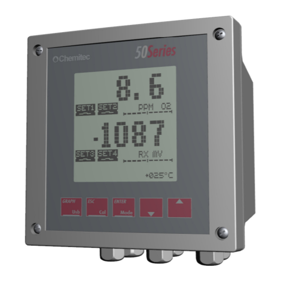
Контроллер управления насосо-дозатором Chemitec 3537 pH / Redox — является оборудованием для бассейна, осуществляет дезинфекцию и водоподготовку бассейна, путем: индикации, измерения и регулирования показателя хлора на основе показаний датчика pH или Redox воды в бассейне. Управляется и контролируется с помощью 5-и плёночных кнопок ЖКИ-дисплея (128×128 пикселей,). Одновременное отображение измеряемых параметров. Установка станции — настенное, на пластиковой монтажной панели. Это устройство было разработано для непрерывного анализа значения рН/ОВП в различных сферах применения: биореакторы, индустриальная водоподготовка, очистка стоков, рыбоводство, оборотная или питьевая водоподготовка
В контроллере предусмотрен режим управления дозированием — пропорциональный (PROP). Датчик температуры (PT100 / PT1000) позволяет автоматически учитывать контроллеру температурную компенсацию.
Chemitec 3537 оборудован входом напряжения (диапазон от 15 до 30 Vac / Vdc) для приостановки измерения и функции дозирования через удаленную систему.
Chemitec 3537 может быть установлен на панель или на стену с максимальным удалением от датчика 15 метров.
Входы Chemitec 3537 pH / Redox:
- Вход подключения датчиков: pH или Redox
- Вход 15÷30 В перем./пост.тока
- Температурный ввод: PT100 / PT1000 в диапазоне 0 …100°C или ручная настройка и прямой визуальный отсчет
- Сигнальный вход датчика уровня или потока. Вход для сухого контакта или полупроводника (открытый коллектор), напряжение 5 В пост., макс. ток 6 мА.
- USB Порт-Вход с активацией микропроцессора и дисплеем без подсветки.
- Электропитание прибора — Входы: 100÷240 В перем. или 12÷32 В пост. (24 В перем.)
Выходы Chemitec 3537 pH / Redox:
-
Частотные выходы SSR1: Твердотелое контактноереле (60 В пост/перем, 100 мА)
R1 и R2: Электромеханические реле (250 В перем или 30 В пост., 5 A Резистивный) - mA1: Токовый выход 4÷20 мА (800 Ом)
Функции и возможности Chemitec 3537 pH / Redox:
• Измерение pH/ОВП
• Измерение Температуры с датчиками PT100 / PT1000
• Автоматическая Температурная Компенсация
• Панель Программирования с клавиатурой из 5- ти кнопок
• Графический Дисплей, 128×128 пикселей, с подсветкой
• 1 Програмируемый Аналоговый Выход
• 1 Частотный Программируемый ВЫход
• 2 Релейных Выхода для Корректировки Пороговых Значений, Промывки и Аварийного Сингала.
• 1 Цифровой Вход для блокировки дозации
Технические характеристики контроллера Chemitec 3537 K40 pH / Redox:
| Технические данные | Единицы измерения | Значение параметра |
| Напряжение питания | Вольт | 85-265 / 50/60 Гц |
| Вход датчика Cl | нет | |
| Вход датчика pH | есть | |
| Вход датчика Redox | есть | |
| Вход датчика температуры °C | есть | |
| Вход датчика потока | есть | |
| Диапазон измерений уровня хлора, точность 1% F. S. | ppm | — |
| Диапазон измерений уровня pH Точность: ± 0.10 pH. Шаг измерений: ± 0.01 pH |
pH | 0.00 ÷ 14.00 |
| Диапазон измерений уровня pH Точность: ± 5 мВ. Шаг измерений: ± 1 мВ |
мВ | ± 2000 м |
| Диапазон измерений температуры воды Т° Шаг измерений ± 0.1°C. Точность ± 1.0°C | °C | -10 … +100 °C |
| Диапазон измерений датчика потока | Гц/вольт | / 15..30 |
| Потребляемая мощность контроллера | Вт | 3,5 — 5 |
| Тип управления | — | стационарное/дистанционное |
| Класс защиты | IP | IP65 |
| Температура окружающего воздуха | °C | -10 ÷ +50° |
| Температура протока ячейки, макс | °C | — |
| Влажность окружающего воздуха, не более | % | 0% ÷ 95% Без Конденсата |
| Размеры контроллера | мм | 96x96x130 |
| Вес | кг | 0,310 |
Подключение контроллера Chemitec 3537 pH / Redox

| N° (ТЕРМИНАЛА) | СИМВОЛ | ОПИСАНИЕ |
| 1 | L / + | Питание (Фаза) |
| 2 | N / — | Питание (Нейтраль) |
| 3 | SSR1 (+) | Частотный выход 1 (SSR1 +) |
| 4 | SSR1 (-) | Частотный выход 1 (SSR1 -) |
| 5 | NOT USED | НЕ ИСПОЛЬЗУЕТСЯ |
| 6 | NOT USED | НЕ ИСПОЛЬЗУЕТСЯ |
| 7 | RL1 NA | Релейный контакт 1 |
| 8 | RL1 COM | Релейный контакт 1 |
| 9 | RL2 COM | Релейный контакт 2 |
| 10 | RL2 NA | Релейный контакт 2 |
| 11 | OUT mA1 (+) | Токовый выход 1 (ВЫХОД mA1 +) |
| 12 | OUT mA1 (-) | Токовый выход 1 (ВЫХОД mA1 -) |
| 13-24 | NOT PRESENT | ОТСУТСТВУЮТ |
| 25 | REED (+) | Вход датчика потока/уровня (+) |
| 26 | REED (-) | Вход датчика потока/уровня (-) |
| 27 | pH / ORP (+) | pH/ОВП Вход Датчика (+) (сердечник) |
| 28 | NOT USED | НЕ ИСПОЛЬЗУЕТСЯ |
| 29 | NOT PRESENT | ОТСУТСТВУЕТ |
| 30 | pH / ORP (-) | pH/ОВП Вход Датчика (-) (оплетка) |
| 31 | GND | ЗАЗЕМЛЕНИЕ Раствор/Щит |
| 32 | RTD (+) | Вход датчика Температуры PT100 или PT1000 (белый) |
| 33 | RTD SENSE | Вход датчика Температуры PT100 или PT1000 (синий) |
| 34 | RTD GND | Вход датчика Температуры PT100 или PT1000 (зелёный + желтый) |
| USB | USB PORT | (*) USB Порт для обновления Программного Обеспечения |
(* Загрузка или Выгрузка данных невозможна)
-
Contents
-
Table of Contents
-
Bookmarks
Quick Links
50 SERIES
MULTIPARAMETER PLUG & PLAY
ANALYZER
TECHNICAL MANUAL
P/N:
………………….
Rev. 0 Ver. 1.2
EDITION June 2012
Related Manuals for Chemitec 50 SERIES
Summary of Contents for Chemitec 50 SERIES
-
Page 1
50 SERIES MULTIPARAMETER PLUG & PLAY ANALYZER TECHNICAL MANUAL P/N: …………………. Rev. 0 Ver. 1.2 EDITION June 2012… -
Page 2
The products, materials, software and services presented in this document are subject to development and with regards to presentation and performance characteristics, CHEMITEC s.r.l. reserves the right to carry out any modifications without prior notice. COPYRIGHT The reproduction or copy of this manual, even partial, and using any procedure is strictly prohibited. -
Page 3: Table Of Contents
CONNECTIONS TO THE POWER SUPPLY ………………17 3.1.2.1 Electrical Connections to the dosage systems (Users) ……………. 17 3.1.2.1.1 Connection terminal box for 50 Series ………………18 3.1.2.2 Connections to the Power Supply ………………….19 3.1.3 OXYGEN PROBE CONNECTION ………………….19 3.1.4…
-
Page 4
SPECIAL CAUTIONS FOR CRITICAL COMPONENTS …………….50 APPENDIX: TABLES OF SOLUBILITY AND CONVERSION-CORRECTION FACTORS ….51 MODBUS PROTOCOL ……………………….52 WARRANTY …………………………… 60 REQUEST FOR ASSISTANCE ……………………… 61 PROCEDURE OF REQUEST FOR TECHNICAL ASSISTANCE TECNICA ……….61 MAIN CHEMITEC OFFICES ……………………. 61… -
Page 5: General
If for any reason it is ruined, incomplete or inadequate please contact CHEMITEC in order to reintegrate or replace the non-compliant manual immediately.
-
Page 6: Declaration Of Responsibility By The Manufacturer
MULTIPARAMETER PLUG & PLAY ANALYZER TECHNICAL MANUAL P/N XXX-0000 Rev.0 Ver.1.0 DECLARATION OF RESPONSIBILITY BY THE MANUFACTURER CHEMITEC will be held responsible for the safety, reliability and performance of the equipment only if used in compliance with the following conditions: •…
-
Page 7: Safety Of The Operative Environment
SAFETY OF THE OPERATIVE ENVIRONMENT • The panel of the 50 Series device is protected against the introduction of liquids. Avoid subject the equipment to the risk of dripping water, sprays of water or immersion in water and the use in environments in which such risks may be present. Equipment in which liquids may have accidentally penetrated must be immediately switched off, cleaned and controlled by authorised and qualified personnel.
-
Page 8: Graphic Symbols
50 Series MULTIPARAMETER PLUG & PLAY ANALYZER TECHNICAL MANUAL P/N XXX-0000 Rev.0 Ver.1.0 GRAPHIC SYMBOLS The following table illustrates the drawings, the relative description and the position of all graphic symbols present on the equipment panels and on any other equipment or external devices to which they may be connected.
-
Page 9: Plate Details
Max 115V on relay outputs INFORMATION ON RECYCLING AND USE OF MATERIALS CHEMITEC, in accordance with specific European regulations, aims at constant improvement of development and of production procedures of its equipment with the objective of drastically reducing the negative impact on the environment caused by parts, components, consumption materials, packaging and the equipment itself at the end of its life cycle.
-
Page 10: General Description
• Fish farm • Primary Water, Drinking Water Figure 1 – Wall mounting Multiparameter analyzer (50 Series) P ARAMETERS DETECTED BY THE INSTRUMENT • MEASURING OF PH • MEASURING OF ORP • MEASURING OF TURBIDITY • MEASURING OF SUSPENDED SOLIDS •…
-
Page 11: Technical Characteristics For Dissolved Oxygen
50 Series MULTIPARAMETER PLUG & PLAY ANALYZER TECHNICAL MANUAL P/N XXX-0000 Rev.0 Ver.1.0 • «CAL» Function Key to direct access to the calibration menu • «GRAPH» Function Key to direct access to the graphs of measure • “USB” Function Key for data download on USB support •…
-
Page 12: Technical Characteristics For Redox Measuring
50 Series MULTIPARAMETER PLUG & PLAY ANALYZER TECHNICAL MANUAL P/N XXX-0000 Rev.0 Ver.1.0 2.2.3 TECHNICAL CHARACTERISTICS FOR REDOX MEASURING Measurement range ± 1500mV Resolution ± 1mV Precision ± 0.2% f.s. 2.2.4 TECHNICAL CHARACTERISTICS FOR TURBIDITY AND SUSPENDED SOLIDS Due to the connected probe:…
-
Page 13
50 Series MULTIPARAMETER PLUG & PLAY ANALYZER TECHNICAL MANUAL P/N XXX-0000 Rev.0 Ver.1.0 1 Ampere, the maximum tension commutable is 230Vac, maximum power 230VA on a resistive load Alarm: Function Delay, Faults and Min./Max. Delay time 00:00 ÷ 99:99 min… -
Page 14: Controls, Indicators And Connections
50 Series MULTIPARAMETER PLUG & PLAY ANALYZER TECHNICAL MANUAL P/N XXX-0000 Rev.0 Ver.1.0 CONTROLS, INDICATORS AND CONNECTIONS Figure 2 – Wall instrument, front panel 1. Visualizer with LCD Display 2. UP key 3. ESC key 4. ENTER key 5. DOWN key 6.
-
Page 15: Graphic Display
50 Series MULTIPARAMETER PLUG & PLAY ANALYZER TECHNICAL MANUAL P/N XXX-0000 Rev.0 Ver.1.0 GRAPHIC DISPLAY The graphic display allows for visualization of the various programming menus and, in the measuring method (RUN), visualization of the measurements and of the state of operation.
-
Page 16: Division Of The Graphical Display Into Areas In The Run Method
50 Series MULTIPARAMETER PLUG & PLAY ANALYZER TECHNICAL MANUAL P/N XXX-0000 Rev.0 Ver.1.0 2.4.2 DIVISION OF THE GRAPHICAL DISPLAY INTO AREAS IN THE RUN METHOD Figure 4 – Graphic display — divided up into areas In the following table, for every area of the display indicated in figure 3, the symbols that may appear during functioning of the device in a measurement method (RUN) are represented and briefly described.
-
Page 17
50 Series MULTIPARAMETER PLUG & PLAY ANALYZER TECHNICAL MANUAL P/N XXX-0000 Rev.0 Ver.1.0 GRAPHIC VISUAL REPRESENTATION DESCRIPTION ZONE Set2 — Open Relay Set2 — Closed Relay Set2 — Timed Active Threshold Relay Open Set2 — Timed Deactivated Threshold Relay Open Set2 –… -
Page 18
50 Series MULTIPARAMETER PLUG & PLAY ANALYZER TECHNICAL MANUAL P/N XXX-0000 Rev.0 Ver.1.0 GRAPHIC VISUAL REPRESENTATION DESCRIPTION ZONE Oxygen measurement unit Oxygen measurement unit Oxygen measurement unit pH measurement unit ORP measurement unit Turbidity and Suspended Solids measurement unit Turbidity and Suspended Solids… -
Page 19
50 Series MULTIPARAMETER PLUG & PLAY ANALYZER TECHNICAL MANUAL P/N XXX-0000 Rev.0 Ver.1.0 GRAPHIC VISUAL REPRESENTATION DESCRIPTION ZONE 100% of the scale Value outlet n.1 (in mA) Value outlet n.2 (in mA) Value outlet n.1 with PID function PID (in Value outlet n.2 with PID function PID (in… -
Page 20: Installation
TECHNICAL MANUAL P/N XXX-0000 Rev.0 Ver.1.0 INSTALLATION Although the unit is suitable for installation in outdoor environments, it is recommended to avoid direct exposure to sun and weather. Before installing the 50 Series carefully read the instructions provided below. COMPOSITION OF THE SUPPLY The supply consists of just one package which contains the following parts: •…
-
Page 21: Connections To The Power Supply
50 Series MULTIPARAMETER PLUG & PLAY ANALYZER TECHNICAL MANUAL P/N XXX-0000 Rev.0 Ver.1.0 3.1.2 CONNECTIONS TO THE POWER SUPPLY If possible avoid any cables destined for high power use to be positioned close to the device as they may cause faults of an inductive nature to the analogical section of the instrument.
-
Page 22: 3.1.2.1.1 Connection Terminal Box For 50 Series
Figure 6 Examples of connection with users NOTE The layouts indicated above are typically indicative as details of all of the protection and safety devices necessary are missing. 3.1.2.1.1 Connection terminal box for 50 Series Figure 7 Connections terminal box CLAMP Nr. GRAPHIC…
-
Page 23: 3.1.2.2 Connections To The Power Supply
3.1.3 OXYGEN PROBE CONNECTION The 50 Series instrument must be connected only with 2 optical digital probes having different addresses: ID10 for the first, ID11 for the second probe. When purchasing the instrument and the probes, items leave the factory with correct IDs set. So by paralleling the two probes everything will work.
-
Page 24: Ph / Orp, Turbidity / S.s. Probe Connection
50 Series MULTIPARAMETER PLUG & PLAY ANALYZER TECHNICAL MANUAL P/N XXX-0000 Rev.0 Ver.1.0 CAUTION Pay special attention to the formation of air bubbles: they may interfere with the reading of oxygen. To overcome this problem, use the 45° tilt kit of the probe, so that the bubbles can slip upwards.
-
Page 25: Methods Of Use
50 Series MULTIPARAMETER PLUG & PLAY ANALYZER TECHNICAL MANUAL P/N XXX-0000 Rev.0 Ver.1.0 METHODS OF USE COMPOSITION OF THE MEASURING SYSTEM 4.1.1 MINIMUM CONFIGURATION Figure 8 Minimum Configuration 4.1.2 MAXIMUM CONFIGURATION Figure 9 Maximum Configuration…
-
Page 26: Start Up Of The System
50 Series MULTIPARAMETER PLUG & PLAY ANALYZER TECHNICAL MANUAL P/N XXX-0000 Rev.0 Ver.1.0 START UP OF THE SYSTEM Once the electronic device and the measuring probe(s) have been connected, programming of the software must be carried out in order to determine “personalisation” of parameters for correct use of the equipment.
-
Page 27: Setup Menu (Temperature — System Setup)
50 Series MULTIPARAMETER PLUG & PLAY ANALYZER TECHNICAL MANUAL P/N XXX-0000 Rev.0 Ver.1.0 By pressing the ESC key the screen will go back to the menu or to the previous function and any variations made will be cancelled. 4.3.1 SETUP MENU (TEMPERATURE – SYSTEM SETUP) 1.
-
Page 28
50 Series MULTIPARAMETER PLUG & PLAY ANALYZER TECHNICAL MANUAL P/N XXX-0000 Rev.0 Ver.1.0 1.20 SETUP SYSTEM 1.280 SENSOR 1.281 PASSWORD ENTER Date/hour System ENTER Communication OXYSMART Password: 0 Language YES/NO Password Display Serial Number Probe available Oxysmart A1) System In this part of the programme which is divided up into 5 functions, the basic functioning parameters of the instrument are set. -
Page 29: Setup Menu (Digital Input)
50 Series MULTIPARAMETER PLUG & PLAY ANALYZER TECHNICAL MANUAL P/N XXX-0000 Rev.0 Ver.1.0 4.3.2 SETUP MENU (DIGITAL INPUT) ENTER + DOWN 1. 0 SETUP Setup System Digital input Measures setup ENTER (B2) (B1) 1.50 DIGITAL INPUT 1.30 DIGITAL INPUT OPEN RLY…
-
Page 30: Setup Menu (Measures Setup — Oxygen)
50 Series MULTIPARAMETER PLUG & PLAY ANALYZER TECHNICAL MANUAL P/N XXX-0000 Rev.0 Ver.1.0 C2) Temperature The Unit of Measurement function allows for the value of the temperature to be visualised in Centigrade or Fahrenheit. Centigrades are set as a default.
-
Page 31: Setup Menu (Measures Setup — Turbidity — Ph — Orp — Nh4+ — No3)
50 Series MULTIPARAMETER PLUG & PLAY ANALYZER TECHNICAL MANUAL P/N XXX-0000 Rev.0 Ver.1.0 D2) Change ID Allows to change the ID of the probe. D3) Step reading OXY Probe Allows to set the time (seconds) how often the instrument performs the measurement of oxygen…
-
Page 32: Menu Setup Oxysmart
50 Series MULTIPARAMETER PLUG & PLAY ANALYZER TECHNICAL MANUAL P/N XXX-0000 Rev.0 Ver.1.0 E2) Measur. Unit Allows to set the measuring unit of the Turbidity, choosing from NTU, FTU, g/l and mg/l. E3) Range Allows to set the range in wich the probe operates. It is possible to choose between 4, 40, 400, 4000 NTU for Turbidity probe and 30 g/l for Suspended Solids probe.
-
Page 33: Menu (Relay Outputs – Set Point 1, 2, 3, 4)
50 Series MULTIPARAMETER PLUG & PLAY ANALYZER TECHNICAL MANUAL P/N XXX-0000 Rev.0 Ver.1.0 4.3.7 MENU (RELAY OUTPUTS – SET POINT 1, 2, 3, 4) 2.0 USCITA 2.1 RELAY OUTPUTS Set point 1 Measure 1 ENTER ENTER ENTER Relay Outputs Set Point 2 Measure 1…
-
Page 34
50 Series MULTIPARAMETER PLUG & PLAY ANALYZER TECHNICAL MANUAL P/N XXX-0000 Rev.0 Ver.1.0 Furthermore by acting on the Time ON and Time OFF parameters it is possible to define a DELAY time or a TIMED operation of the Relay during its activation. -
Page 35
50 Series MULTIPARAMETER PLUG & PLAY ANALYZER TECHNICAL MANUAL P/N XXX-0000 Rev.0 Ver.1.0 Measure Figure 13 – Operation of Relay 1 as PID F3) PID-Frequency By setting the Set Point as PID-Frequency it is possible, through Relay 1, to control a pump directly with impulse inputs. -
Page 36: Outputs Menu (Relay Outputs – Wash, Alarm, Logic Set)
50 Series MULTIPARAMETER PLUG & PLAY ANALYZER TECHNICAL MANUAL P/N XXX-0000 Rev.0 Ver.1.0 4.3.8 OUTPUTS MENU (RELAY OUTPUTS – WASH, ALARM, LOGIC SET) 2.0 OUTPUT ENTER ENTER Relay Outputs B1) Set Point2 Current Output Setup PID DOWN UP/DOWN (G1) (G2)
-
Page 37
50 Series MULTIPARAMETER PLUG & PLAY ANALYZER TECHNICAL MANUAL P/N XXX-0000 Rev.0 Ver.1.0 G1.2) If the relay is set as TEMP 1 or TEMP 2: The relay is set as a temperature relay, within this step it is possibile to set up the Set Point of temperature. -
Page 38: Outputs Menu (Current Output)
50 Series MULTIPARAMETER PLUG & PLAY ANALYZER TECHNICAL MANUAL P/N XXX-0000 Rev.0 Ver.1.0 G3) Logic Set The parameters of the Logic Set determine the functioning of the Alarm Relay. This function is deactivated by default. This function activates an alarm when the measuring values are located outside of a specific “window”.
-
Page 39: Outputs Menu (Setup Pid)
50 Series MULTIPARAMETER PLUG & PLAY ANALYZER TECHNICAL MANUAL P/N XXX-0000 Rev.0 Ver.1.0 UPPER LIMIT: A Measure 1 value of 20mA can be set for output current. The default value depends by the selected parameter to measure and its measuring probe. See the technical data of the probe itself for further informations.
-
Page 40
50 Series MULTIPARAMETER PLUG & PLAY ANALYZER TECHNICAL MANUAL P/N XXX-0000 Rev.0 Ver.1.0 variables. This PID has been designed for those general applications with a fast retroactivity of the system. In reality, the maximum integral and derived times are 5 minutes. -
Page 41: Calibrations Menu
50 Series MULTIPARAMETER PLUG & PLAY ANALYZER TECHNICAL MANUAL P/N XXX-0000 Rev.0 Ver.1.0 4.3.11 CALIBRATIONS MENU This programme phase allows for the instrument calibration with the electrode used. Calibration must be carried out: − When starting the measure instrument / electrode chain the first time −…
-
Page 42
50 Series MULTIPARAMETER PLUG & PLAY ANALYZER TECHNICAL MANUAL P/N XXX-0000 Rev.0 Ver.1.0 pH CALIBRATION SELECTION VALUE ENTER ENTER (J2) (J3) (J1) 3.4 PH CALIBRATION 3.4 PH CALIBRATION 3.4 PH CALIBRATION (I1) 1 point calibration 1 point calibration 1 point calibration… -
Page 43
50 Series MULTIPARAMETER PLUG & PLAY ANALYZER TECHNICAL MANUAL P/N XXX-0000 Rev.0 Ver.1.0 pH calibration: J1) 1 point calibration The 1 point calibration must be carried out using pH7 buffer!! After inserting the temperature compensation value of the calibration solution (if the temperature probe is connected, the temperature will be read automatically) press the ENTER key and dip the pH electrode into the pH7 buffer solution, then press the ENTER key once again. -
Page 44: Orp Calibration
50 Series MULTIPARAMETER PLUG & PLAY ANALYZER TECHNICAL MANUAL P/N XXX-0000 Rev.0 Ver.1.0 J3) Default Reset This programme step allows for the calibration factors to be reset to the original factory ones. To be used when incorrect calibrations are confirmed.
-
Page 45
50 Series MULTIPARAMETER PLUG & PLAY ANALYZER TECHNICAL MANUAL P/N XXX-0000 Rev.0 Ver.1.0 TURBIDITY / SUSPENDED SOLIDS CALIBRATION (S461) SELECTION VALUE ENTER TURBIDITY ENTER (L2) (L1) (L3) 3.1 USER 3.1 USER 3.1 USER Automatic Automatic Automatic K Factor K Factor… -
Page 46
50 Series MULTIPARAMETER PLUG & PLAY ANALYZER TECHNICAL MANUAL P/N XXX-0000 Rev.0 Ver.1.0 OXYGEN CALIBRATION SELECTION VALUE ENTER (M1) (M2) (M3) 3.3 CALIBRATION OXY 3.3 CALIBRATION OXY 3.3 CALIBRATION OXY Automatic Automatic Automatic Manual Manual Manual Default Reset Default Reset… -
Page 47
50 Series MULTIPARAMETER PLUG & PLAY ANALYZER TECHNICAL MANUAL P/N XXX-0000 Rev.0 Ver.1.0 + OR NO CALIBRATION SELECT MEASURE NH4+ or NO3 3.6 NH4 CALIBRATION NH4+ CALIBRATION K+ CALIBRATION ENTER (N1) (N2) (N3) 3.6 NH4 CALIBRATION 3.6 NH4 CALIBRATION 3.6 NH4 CALIBRATION… -
Page 48: Archive Menu
50 Series MULTIPARAMETER PLUG & PLAY ANALYZER TECHNICAL MANUAL P/N XXX-0000 Rev.0 Ver.1.0 TEMPERATURE CALIBRATION 3.0 CALIBRATIONS ENTER TEMP DOWN ENTER (N1) (N2) 3.3 TEMP CALIBRATION 3.3 TEMP CALIBRATION Automatic Automatic Default Reset Default Reset DOWN ENTER ENTER NTC CALIBRATION 3.3 TEMP CALIBRATION…
-
Page 49
50 Series MULTIPARAMETER PLUG & PLAY ANALYZER TECHNICAL MANUAL P/N XXX-0000 Rev.0 Ver.1.0 (P1) (P2) 4.0 ARCHIVE 4.0 ARCHIVE Show Records Show Records ENTER Setup Setup DOWN ENTER ENTER 4.20 SETUP Step 1 min ENTER Archive —> Memory Filli. Empty Archive… -
Page 50: Menu Of Measuring Graphics
50 Series MULTIPARAMETER PLUG & PLAY ANALYZER TECHNICAL MANUAL P/N XXX-0000 Rev.0 Ver.1.0 It is used to clean the memory. CAUTION Once this operation is carried out all measurements stored will be lost. 4.3.13 MENU OF MEASURING GRAPHICS 5.0 GRAPHIC MEASUR 20.00…
-
Page 51: Menu Manual Control
50 Series MULTIPARAMETER PLUG & PLAY ANALYZER TECHNICAL MANUAL P/N XXX-0000 Rev.0 Ver.1.0 4.3.14 MENU MANUAL CONTROL ENTER UP/DOWN UP/DOWN UP/DOWN (Q1) (Q2) (Q3) (Q4) 6.0 MANUAL CONTROL 6.0 MANUAL CONTROL 6.0 MANUAL CONTROL 6.0 MANUAL CONTROL Analog Inputs Analog Inputs…
-
Page 52: Functions In Run
50 Series MULTIPARAMETER PLUG & PLAY ANALYZER TECHNICAL MANUAL P/N XXX-0000 Rev.0 Ver.1.0 4.3.15 FUNCTIONS IN RUN 7.4 O (R1) Setting? 9.8 O All outputs ENTER will be open (ENTER/ESC) 20.5 (R2) PLUG & PLAY PLUG & PLAY ENTER ESC (HOLD ON)
-
Page 53
50 Series MULTIPARAMETER PLUG & PLAY ANALYZER TECHNICAL MANUAL P/N XXX-0000 Rev.0 Ver.1.0 • Status of the Password • Status of measuring and outlet freezing • Value of the Temperature or of the Analogical Outlet 1 or of the Analogical Outlet 2 •… -
Page 54: User Maintenance
50 Series MULTIPARAMETER PLUG & PLAY ANALYZER TECHNICAL MANUAL P/N XXX-0000 Rev.0 Ver.1.0 USER MAINTENANCE SPECIAL CAUTIONS FOR CRITICAL COMPONENTS An LCD (Liquid Crystal Display) is incorporated into the equipment and it contains small amounts of toxic materials. In order to avoid damages to people and to limit the negative effects on the environment, comply…
-
Page 55: Appendix: Tables Of Solubility And Conversion-Correction Factors
50 Series MULTIPARAMETER PLUG & PLAY ANALYZER TECHNICAL MANUAL P/N XXX-0000 Rev.0 Ver.1.0 APPENDIX: TABLES OF SOLUBILITY AND CONVERSION-CORRECTION FACTORS TABLE 1 Solubility of oxygen in water at 760 mm Hg and 100% of relative humidity °C ppm O °C ppm O 14.6…
-
Page 56: Modbus Protocol
50 Series MULTIPARAMETER PLUG & PLAY ANALYZER TECHNICAL MANUAL P/N XXX-0000 Rev.0 Ver.1.0 MODBUS PROTOCOL Characteristics • Standard MODBUS Protocol RTU type • Physical Layer: two wires RS485 (half-duplex) • Alternative Physical Layer: USB • 8 bit, Equality N, 1 Stop bit •…
-
Page 57
50 Series MULTIPARAMETER PLUG & PLAY ANALYZER TECHNICAL MANUAL P/N XXX-0000 Rev.0 Ver.1.0 (0=TSS/FTU1, 1=TSS/FTU2, 2=OX1, 3=OX2, 4=PH1 5=PH2,6=RX1,7=RX2,8=CX1,9=CX2) (for discrimination between TSS e FTU see parameter 168) 08 Measure 1 value (main_val[meas_sel[0]]) 10 Measure 2 value (main_val[meas_sel[1]]) 12 Temperature 1 value (main_val[TP_1]) -
Page 58
50 Series MULTIPARAMETER PLUG & PLAY ANALYZER TECHNICAL MANUAL P/N XXX-0000 Rev.0 Ver.1.0 138 Seconds for temporized alarm (alr_sec) 140 Permanence field (meas_perm) 142 Permanence time hours (cpalr_hour) 144 Permanence time min (step 15min)(cpalr_hour) 146 Archive registrations range (reg_min) 148 Day… -
Page 59
50 Series MULTIPARAMETER PLUG & PLAY ANALYZER TECHNICAL MANUAL P/N XXX-0000 Rev.0 Ver.1.0 11 Sign for Measure1 PID algorythm (0=Direct, 1=Inverse) (pid_cnsgn[meas_sel[0]]) 12 Sign for Measure2 PID algorythm (0=Direct, 1=Inverse) (pid_cnsgn[meas_sel[1]]) 13 Analog Out 1 functioning (0=Proporzionale, 1=PID) (pid2_flag[0]) 14 Analog Out 2 functioning (0=Proporzionale, 1=PID) (pid2_flag[1]) -
Page 60
50 Series MULTIPARAMETER PLUG & PLAY ANALYZER TECHNICAL MANUAL P/N XXX-0000 Rev.0 Ver.1.0 104 Set Point 3: Period of PWM max 999 sec (set_pid_period[]) 106 Set Point 3: MAX Frequency imp/h (max. 7200 )(set_pid_freq[]) 108 Set Point 4: Functioning (0=threshold, 1=PWM, 2=Frequency)(set4_typ) 110 Set Point 4: Period of PWM max 999 sec (set_pid_period[]) 112 Set Point 4: MAX Frequency imp/h (max. -
Page 61
50 Series MULTIPARAMETER PLUG & PLAY ANALYZER TECHNICAL MANUAL P/N XXX-0000 Rev.0 Ver.1.0 Archive download at record blocks Sequency: 1. Single record size request. 2. Existing record number request. 3. Current record request 4. Record acquiring cycle a. If previous request goes well Request next record b. -
Page 62
50 Series MULTIPARAMETER PLUG & PLAY ANALYZER TECHNICAL MANUAL P/N XXX-0000 Rev.0 Ver.1.0 Answer Byte Description Device Slave Number BHIST_ARC_FN = 0x44 (Function) BHIST_ARC_NUM_REC = 0x03 (Subfunction) Numero Records (lo) Numero Records (hi) CRC (lo) CRC (hi) Current record request… -
Page 63
50 Series MULTIPARAMETER PLUG & PLAY ANALYZER TECHNICAL MANUAL P/N XXX-0000 Rev.0 Ver.1.0 If Data size=0 : a record over than the the existings has prompted Reset archive request Request Byte Description Device Slave Number HIST_ARC_RESET = 0x45 (Function) CRC (lo) -
Page 64: Warranty
TECHNICAL MANUAL P/N XXX-0000 Rev.0 Ver.1.0 WARRANTY Chemitec s.r.l. will replace or repair at its own sole option, those parts that may eventually manifest defects in manufacturing or operating, despite of a diligent and proper use by the customer. The defective product, or considered such, must be sent free of charge to the Chemitec Factory, via I.Newton 28, 50018 Scandicci, Florence (Italy) and will be returned, after the reparation, at…
-
Page 65: Request For Assistance
In the case of a fault to the equipment or in the case of partial or incorrect functioning that cannot be resolved through the ordinary maintenance operations described in this manual or in the documentation attached, we kindly ask you to contact a CHEMITEC office or branch or your nearest dealer or authorised assistance centre.
| Основные | |
|
Гарантия |
6 мес |
|---|---|
|
Серия |
H |
|
Среды |
Бензин/ Вода без включений/ Кислоты минеральные и органические / Масло растительное/ Нефтепродукты/ Химические реагенты/ Щелочи |
|
Сфера применения |
Бассейны (добавки)/ Водоподготовка/ Деаэрация / Косметическая промышленность/ Лакокрасочная промышленность/ Легкая промышленность/ Нефтяная промышленность / Обеззараживание воды/ Очистка сточных вод/ Прачечная/ Производство напитков/ Сельское хозяйство/ Текстильная промышленность/ Химическая промышленность / Химчистка |
|
Тип насоса |
Насосы дозаторы |
| Гидравлические характеристики | |
|
Макс. производительность (м³/час) |
0,008 |
|
Объем импульса (мл) |
0.43-0.83 |
| Данные электрооборудования | |
|
Мощность двигателя (кВт) |
0.015 |
| Конструкция | |
|
Частота хода в минуту |
160 |
-
Contents
-
Table of Contents
-
Bookmarks
Quick Links
50 SERIES 8 PARAMETERS
MULTIPARAMETER PLUG & PLAY
ANALYZER
TECHNICAL MANUAL
P/N:
………………….
Rev. 1 Ver. 1
EDITION Agoust 2018 draft
Related Manuals for Chemitec 50 Series
Summary of Contents for Chemitec 50 Series
-
Page 1
50 SERIES 8 PARAMETERS MULTIPARAMETER PLUG & PLAY ANALYZER TECHNICAL MANUAL P/N: …………………. Rev. 1 Ver. 1 EDITION Agoust 2018 draft… -
Page 2
GENERAL CLAUSES Despite the fact that the utmost attention has been given taken in the preparation of this document, CHEMITEC s.r.l. cannot guarantee the accuracy of all information contained and cannot be held responsible for any consequent mistakes or damages that may arise from its use or application. -
Page 3: Table Of Contents
CONNECTIONS TO THE POWER SUPPLY ………………15 3.1.2.1 Electrical Connections to the dosage systems (Users) ……………. 16 3.1.2.1.1 Connection terminal box for 50 Series ………………17 3.1.2.1.2 Connection terminal box for J-Box ………………..19 3.1.2.2 Connections to the Power Supply ………………….20 3.1.3…
-
Page 4
SPECIAL CAUTIONS FOR CRITICAL COMPONENTS …………….37 APPENDIX: TABLES OF SOLUBILITY AND CONVERSION-CORRECTION FACTORS ….38 MODBUS PROTOCOL ……………………….39 WARRANTY …………………………… 49 REQUEST FOR ASSISTANCE ……………………… 50 PROCEDURE OF REQUEST FOR TECHNICAL ASSISTANCE …………..50 MAIN CHEMITEC OFFICES ……………………. 50… -
Page 5: General
If for any reason it is ruined, incomplete or inadequate please contact CHEMITEC in order to reintegrate or replace the non-compliant manual immediately.
-
Page 6: Declaration Of Responsibility By The Manufacturer
/ instrument DECLARATION OF RESPONSIBILITY BY THE MANUFACTURER CHEMITEC will be held responsible for the safety, reliability and performance of the equipment only if used in compliance with the following conditions: •…
-
Page 7: Safety Of The Operative Environment
SAFETY OF THE OPERATIVE ENVIRONMENT • The panel of the 50 Series device is protected against the introduction of liquids. Avoid subject the equipment to the risk of dripping water, sprays of water or immersion in water and the use in environments in which such risks may be present. Equipment in which liquids may have accidentally penetrated must be immediately switched off, cleaned and controlled by authorised and qualified personnel.
-
Page 8: Graphic Symbols
50 Series 8P MULTIPARAMETER PLUG & PLAY ANALYZER TECHNICAL MANUAL P/N XXX-0000 Rev.4 Ver.1.1 Therefore, we recommend that service personnel and/or maintenance personnel operate with the utmost care, pointing out any changes to the safety parameters immediately, in order to avoid the creation of any potentially dangerous situations.
-
Page 9: Caution Symbol
IP66 INFORMATION ON RECYCLING AND USE OF MATERIALS CHEMITEC, in accordance with specific European regulations, aims at constant improvement of development and of production procedures of its equipment with the objective of drastically reducing the negative impact on the environment caused by parts, components, consumption materials, packaging and the equipment itself at the end of its life cycle.
-
Page 10: Special Attention To Critical Components
50 Series 8P MULTIPARAMETER PLUG & PLAY ANALYZER TECHNICAL MANUAL P/N XXX-0000 Rev.4 Ver.1.1 The equipment is made in such a way as to guarantee the easy separation or dismantling of the materials containing contaminants compared with others, in particular during maintenance operations and the replacement of parts.
-
Page 11: General Description
Treatment and Discharge of Industrial Water • Fish farm • Primary Water, Drinking Water Figure 1 – Wall mounting Multiparameter analyzer (50 Series) P ARAMETERS DETECTED BY THE INSTRUMENT • MEASURING OF PH • MEASURING OF ORP • MEASURING OF INFRARED AND NEFELOMETRIC TURBIDITY •…
-
Page 12: Main Charactheristics
50 Series 8P MULTIPARAMETER PLUG & PLAY ANALYZER TECHNICAL MANUAL P/N XXX-0000 Rev.4 Ver.1.1 MAIN CHARACTHERISTICS • Up to four simultaneous digital measurements and a fifth analogue measure 4-20mA. • Measuring of Temperature using the PT100/PT1000 probe • Programming key pad with 5 keys •…
-
Page 13: Technical Characteristics For Turbidity And Suspended Solids
50 Series 8P MULTIPARAMETER PLUG & PLAY ANALYZER TECHNICAL MANUAL P/N XXX-0000 Rev.4 Ver.1.1 2.2.4 TECHNICAL CHARACTERISTICS FOR TURBIDITY AND SUSPENDED SOLIDS Due to the connected probe: Digital Probe Measuring Range / Measuring Unit S461LT 0.00÷10.00 / 000.00÷100.00 NTU 0 ÷ 4 NTU S461T 0 ÷…
-
Page 14: Technical Characteristics For Secondary Temperature Measuring
50 Series 8P MULTIPARAMETER PLUG & PLAY ANALYZER TECHNICAL MANUAL P/N XXX-0000 Rev.4 Ver.1.1 2.2.12 TECHNICAL CHARACTERISTICS FOR SECONDARY TEMPERATURE MEASURING Sensor PT100/PT1000 Measurement range 0 ÷ +130°C 2.2.13 TECHNICAL CHARACTERISTICS FOR 4-20MA AUX INPUT MEASURING Measurement range 4-20Ma Freely programmable measure 2.2.14…
-
Page 15: Controls, Indicators And Connections
50 Series 8P MULTIPARAMETER PLUG & PLAY ANALYZER TECHNICAL MANUAL P/N XXX-0000 Rev.4 Ver.1.1 CONTROLS, INDICATORS AND CONNECTIONS Figure 2 – Wall instrument, front panel 1. Visualizer with LCD Display 2. UP key 3. ESC key 4. ENTER key 5. DOWN key 6.
-
Page 16: Graphic Display
50 Series 8P MULTIPARAMETER PLUG & PLAY ANALYZER TECHNICAL MANUAL P/N XXX-0000 Rev.4 Ver.1.1 GRAPHIC DISPLAY The graphic display allows for visualization of the various programming menus and, in the measuring method (RUN), visualization of the measurements and of the state of operation.
-
Page 17: Division Of The Graphical Display Into Areas In The Run Method
50 Series 8P MULTIPARAMETER PLUG & PLAY ANALYZER TECHNICAL MANUAL P/N XXX-0000 Rev.4 Ver.1.1 2.4.2 DIVISION OF THE GRAPHICAL DISPLAY INTO AREAS IN THE RUN METHOD Each of the channels shows the value of the measurement, the state of the assigned relays, the value of the current output and the possible temperature value.
-
Page 18: Installation
TECHNICAL MANUAL P/N XXX-0000 Rev.4 Ver.1.1 INSTALLATION Although the unit is suitable for installation in outdoor environments, it is recommended to avoid direct exposure to sun and weather. Before installing the 50 Series carefully read the instructions provided below. COMPOSITION OF THE SUPPLY The supply consists of just one package which contains the following parts: •…
-
Page 19: Connections To The Power Supply
50 Series 8P MULTIPARAMETER PLUG & PLAY ANALYZER TECHNICAL MANUAL P/N XXX-0000 Rev.4 Ver.1.1 3.1.2 INSTALLATION OF 144X144 ELECTRICAL PANEL DEVICE The wall must be perfectly smooth in order to allow for perfect adhesion of the electrical panel close to the device.
-
Page 20: Electrical Connections To The Dosage Systems (Users)
50 Series 8P MULTIPARAMETER PLUG & PLAY ANALYZER TECHNICAL MANUAL P/N XXX-0000 Rev.4 Ver.1.1 CAUTION The electric line must be fitted with a suitable life-saving device and magneto-thermal, in compliance with correct installation norms. The supply disconnecting device must be easily accessible after installing the instrument and must be marked as the disconnection of the unit.
-
Page 21: 3.1.3.1.1 Connection Terminal Box For 50 Series
Figure 7 Examples of connection with users NOTE The layouts indicated above are typically indicative as details of all of the protection and safety devices necessary are missing. 3.1.3.1.1 Connection terminal box for 50 Series Figure 8 Connections terminal box for 50Series CLAMP GRAPHIC…
-
Page 22
50 Series 8P MULTIPARAMETER PLUG & PLAY ANALYZER TECHNICAL MANUAL P/N XXX-0000 Rev.4 Ver.1.1 CLAMP GRAPHIC DESCRIPTION RS485 (B-) Relay for Wash and Temp (N.C. contact) Relay for Wash and Temp (N.O. contact) Relay for Alarm (N.C. contact) Relay for Alarm (N.O. contact) Relay for Set Point 4 (N.C. -
Page 23: 3.1.3.1.2 Connection Terminal Box For J-Box
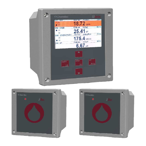
50 Series 8P MULTIPARAMETER PLUG & PLAY ANALYZER TECHNICAL MANUAL P/N XXX-0000 Rev.4 Ver.1.1 In case of 3 wires level probe connection:: CLAMP GRAPHIC DESCRIPTION Blue Wire Level Sensor Digital input (-) Brown Wire Level Sensor Digital input (+) Black Wire Level Sensor 3.1.3.1.2 Connection terminal box for J-Box…
-
Page 24: 3.1.3.2 Connections To The Power Supply
The J-Box is powered by the 50Series instrument connected. 3.1.4 DIGITAL PROBES CONNECTION The 50 Series in its stand-alone configuration can be connected with up to 2 digital probes having different addresses (see figure 9). Power Supply Figure 10 Connections with 2 digital probes…
-
Page 25
50 Series 8P MULTIPARAMETER PLUG & PLAY ANALYZER TECHNICAL MANUAL P/N XXX-0000 Rev.4 Ver.1.1 The instrument must be connected with the J-Box in order to connect the entire system with up to 4 digital probes having different addresses (see figure 10, next page). -
Page 26
50 Series 8P MULTIPARAMETER PLUG & PLAY ANALYZER TECHNICAL MANUAL P/N XXX-0000 Rev.4 Ver.1.1 Power Supply Figure 12.1 Connections with J-Box and 8 probes The display page allows you to display 4 measurements at the same time, if you want to see the other 4 measurements simply change pages… -
Page 27: Methods Of Use
50 Series 8P MULTIPARAMETER PLUG & PLAY ANALYZER TECHNICAL MANUAL P/N XXX-0000 Rev.4 Ver.1.1 METHODS OF USE START UP OF THE SYSTEM Once the electronic device and the measuring probe(s) have been connected, programming of the software must be carried out in order to determine “personalisation” of parameters for correct use of the equipment.
-
Page 28
50 Series 8P MULTIPARAMETER PLUG & PLAY ANALYZER TECHNICAL MANUAL P/N XXX-0000 Rev.4 Ver.1.1 SERIAL NO. (Allows to visualize the serial number of the device on the display) PROBE AVAILABLE (Allows to manually choose the type of connected probes) DIGITAL INPUT (Permette di abbinare l’evento di chiusura ingresso digitale all’apertura dei relè… -
Page 29: Outputs Menu
50 Series 8P MULTIPARAMETER PLUG & PLAY ANALYZER TECHNICAL MANUAL P/N XXX-0000 Rev.4 Ver.1.1 PROBE AVAILABLE (This menu allows you to check which probes have been recognized by the system and manually add a probe without using the “self-recognition” of the…
-
Page 30
50 Series 8P MULTIPARAMETER PLUG & PLAY ANALYZER TECHNICAL MANUAL P/N XXX-0000 Rev.4 Ver.1.1 Measure Figure 13 – Threshold operation Furthermore by acting on the Time ON and Time OFF parameters it is possible to define a DELAY time or a TIMED operation of the Relay during its activation. -
Page 31
50 Series 8P MULTIPARAMETER PLUG & PLAY ANALYZER TECHNICAL MANUAL P/N XXX-0000 Rev.4 Ver.1.1 PID-PWM By defining the Set Point as PID-PWM, through Relay 1, it is possible to activate a pump with an ON/OFF command almost as if it had a proportional adjustment. For this function the time period must be programmed (in seconds) within which the calculation of the PWM adjustment will come about. -
Page 32
50 Series 8P MULTIPARAMETER PLUG & PLAY ANALYZER TECHNICAL MANUAL P/N XXX-0000 Rev.4 Ver.1.1 The user, in case of alarm, can decide if mA output goes to 4 mA or remains frozen at the last value. The PID function allows for three adjustments to handle the dose. -
Page 33: Calibrations Menu
50 Series 8P MULTIPARAMETER PLUG & PLAY ANALYZER TECHNICAL MANUAL P/N XXX-0000 Rev.4 Ver.1.1 3.3.3 CALIBRATIONS MENU 3.0 CALIBRATIONS (It allows you to perform all calibrations of each probe. Entering the menu you choose which probe calibration, depending on the type of probe connected you can do several calibrations).
-
Page 34
50 Series 8P MULTIPARAMETER PLUG & PLAY ANALYZER TECHNICAL MANUAL P/N XXX-0000 Rev.4 Ver.1.1 If ”Faulty Probe” is displayed, we recommend: To check the electrode physical integrity and the protection cap removing To assure the cleaning of the porous plug, if not, dip the electrode into a regenerant… -
Page 35
50 Series 8P MULTIPARAMETER PLUG & PLAY ANALYZER TECHNICAL MANUAL P/N XXX-0000 Rev.4 Ver.1.1 If you use the probe holder pss8 it is better not to execute the calibration of the first point. Circulate water with known solution, making sure that there are no air bubbles in the circuit: to eliminate them you can create a small pressure partially closing the output stream. -
Page 36
50 Series 8P MULTIPARAMETER PLUG & PLAY ANALYZER TECHNICAL MANUAL P/N XXX-0000 Rev.4 Ver.1.1 + OR NO CALIBRATION AUTOMATIC With the automatic calibration mode, once inserted the probe in a known sample, the user can freely enter the value of the known solution, in this way the reading of the probe on a point is aligned. -
Page 37: Archive Menu
50 Series 8P MULTIPARAMETER PLUG & PLAY ANALYZER TECHNICAL MANUAL P/N XXX-0000 Rev.4 Ver.1.1 CONDUCTIVITY CALIBRATION CALIBRATION The conductivity calibration foresees two calibration points. The first calibration must be done at 0µS !! After inputting the temperature compensation value press ENTER key and dip the probe into a solution at 0µS or expose it to air after proper drying.
-
Page 38: Graphic Measuring Menu
50 Series 8P MULTIPARAMETER PLUG & PLAY ANALYZER TECHNICAL MANUAL P/N XXX-0000 Rev.4 Ver.1.1 archive can be transferred to PC via C_NET software, or saved to an external USB flash drive connected to the USB port of the instrument.) In this part of the programme it is possible to visualise data in the form of a table as long as the archives are not empty.
-
Page 39: Manual Control Menu
50 Series 8P MULTIPARAMETER PLUG & PLAY ANALYZER TECHNICAL MANUAL P/N XXX-0000 Rev.4 Ver.1.1 3.3.6 MANUAL CONTROL MENU 6.0 MANUAL CONTROL (This step of the programme is useful for all functional controls eg. Upon installation to check functioning of the entire system, as it allows you to view and manually activate the inputs and outputs of the device.
-
Page 40
50 Series 8P MULTIPARAMETER PLUG & PLAY ANALYZER TECHNICAL MANUAL P/N XXX-0000 Rev.4 Ver.1.1 • Status of the Washing Relay • System errors • Storage of Data in the Archive • Archive Full Holding the ESC key for 3-4 seconds during the run functions By pressing this key you will enter the probe self-recognizing mode of the instrument. -
Page 41: User Maintenance
50 Series 8P MULTIPARAMETER PLUG & PLAY ANALYZER TECHNICAL MANUAL P/N XXX-0000 Rev.4 Ver.1.1 USER MAINTENANCE SPECIAL CAUTIONS FOR CRITICAL COMPONENTS An LCD (Liquid Crystal Display) is incorporated into the equipment and it contains small amounts of toxic materials. In order to avoid damages to people and to limit the negative effects on the environment,…
-
Page 42: Appendix: Tables Of Solubility And Conversion-Correction Factors
50 Series 8P MULTIPARAMETER PLUG & PLAY ANALYZER TECHNICAL MANUAL P/N XXX-0000 Rev.4 Ver.1.1 APPENDIX: TABLES OF SOLUBILITY AND CONVERSION-CORRECTION FACTORS TABLE 1 Solubility of oxygen in water at 760 mm Hg and 100% of relative humidity °C ppm O °C…
-
Page 43: Modbus Protocol
50 Series 8P MULTIPARAMETER PLUG & PLAY ANALYZER TECHNICAL MANUAL P/N XXX-0000 Rev.4 Ver.1.1 MODBUS PROTOCOL Characteristics • Standard MODBUS Protocol RTU type • Physical Layer: two wires RS485 (half-duplex) • Alternative Physical Layer: USB • 8 bit, Equality N, 1 Stop bit •…
-
Page 44
50 Series 8P MULTIPARAMETER PLUG & PLAY ANALYZER TECHNICAL MANUAL P/N XXX-0000 Rev.4 Ver.1.1 00 Instrument name (‘504P’) 4 bytes ASCII 02 Instrument Serial Number (0…65535) 04 ModBus ID (1…254) 06 Probe Type 1 (meas_sel[0]) (see probe Type Codes) 08 Probe Type 2 (meas_sel[1]) -
Page 45
50 Series 8P MULTIPARAMETER PLUG & PLAY ANALYZER TECHNICAL MANUAL P/N XXX-0000 Rev.4 Ver.1.1 242 Measure Unit 1 (characters 5,6,7,8) (read only) 244 Measure Unit 2 (characters 1,2,3,4) (read only) 246 Measure Unit 2 (characters 5,6,7,8) (read only) 248 Measure Unit 3 (characters 1,2,3,4) (read only) -
Page 46
50 Series 8P MULTIPARAMETER PLUG & PLAY ANALYZER TECHNICAL MANUAL P/N XXX-0000 Rev.4 Ver.1.1 2 consecutive registers of the 4 bytes that make up the floating point variable. Because each value has two Modbus registers (4 bytes) and that the values begin to even address registers, was introduced a control that the Starting Address of registers required is even and that the number of registers required is even itself. -
Page 47
50 Series 8P MULTIPARAMETER PLUG & PLAY ANALYZER TECHNICAL MANUAL P/N XXX-0000 Rev.4 Ver.1.1 218 AUX Measure name 1 (characters 5,6,7,8) 220 AUX Measure unit (characters 1,2,3,4) 222 AUX Measure unit (characters 5,6,7,8) -
Page 48
50 Series 8P MULTIPARAMETER PLUG & PLAY ANALYZER TECHNICAL MANUAL P/N XXX-0000 Rev.4 Ver.1.1 Archive download at record blocks Sequency: 1. Single record size request. 2. Existing record number request. 3. Current record request 4. Record acquiring cycle a. If previous request goes well Request next record b. -
Page 49
50 Series 8P MULTIPARAMETER PLUG & PLAY ANALYZER TECHNICAL MANUAL P/N XXX-0000 Rev.4 Ver.1.1 Answer Byte Description Device Slave Number BHIST_ARC_FN = 0x44 (Function) BHIST_ARC_NUM_REC = 0x03 (Subfunction) Numero Records (lo) Numero Records (hi) CRC (lo) CRC (hi) Current record request… -
Page 50
50 Series 8P MULTIPARAMETER PLUG & PLAY ANALYZER TECHNICAL MANUAL P/N XXX-0000 Rev.4 Ver.1.1 If Data size=0 : a record over than the the existings has prompted Reset archive request Request Byte Description Device Slave Number HIST_ARC_RESET = 0x45 (Function) -
Page 51
50 Series 8P MULTIPARAMETER PLUG & PLAY ANALYZER TECHNICAL MANUAL P/N XXX-0000 Rev.4 Ver.1.1 bit4 = (Alarm) bit5 = (Wash) -
Page 52
50 Series 8P MULTIPARAMETER PLUG & PLAY ANALYZER TECHNICAL MANUAL P/N XXX-0000 Rev.4 Ver.1.1 PROBE TYPE CODE FTU_1 //Photometric Turbidimeter Probe FTU_2 //Photometric Turbidimeter Probe FTU_3 //Photometric Turbidimeter Probe FTU_4 //Photometric Turbidimeter Probe OX_1 //Chemitec Oxygen probe OX_2 //Chemitec Oxygen probe… -
Page 53: Warranty
MULTIPARAMETER PLUG & PLAY ANALYZER TECHNICAL MANUAL P/N XXX-0000 Rev.4 Ver.1.1 WARRANTY Chemitec s.r.l. will replace or repair at its own sole option, those parts that may eventually manifest defects in manufacturing or operating, despite of a diligent and proper use by the customer.
-
Page 54: Request For Assistance
In the case of a fault to the equipment or in the case of partial or incorrect functioning that cannot be resolved through the ordinary maintenance operations described in this manual or in the documentation attached, we kindly ask you to contact a CHEMITEC office or branch or your nearest dealer or authorised assistance centre.