Время на прочтение
15 мин
Количество просмотров 354K
Данная статья является первой в планируемом цикле статей по изучению программирования микроконтроллеров. Изучая различные материалы я отметил, что практически все они начинаются с того, что новичку предлагается скачать (или использовать идущую со средой разработки) библиотеку для работы с периферийными устройствами и использовать ее для написания своей первой программы (обычно мигание светодиодом).
Меня это сильно удивило. Если верить данным статьям, для программирования не обязательно даже читать документацию к программируемому контроллеру. Меня же учили премудростям «железного программирования» совершенно иначе.
В этой статье, путь от фразы «Да, я хочу попробовать!» до радостного подмигивания светодиода, будет значительно длиннее чем у других авторов. Я постараюсь раскрыть аспекты программирования микроконтроллеров, которые прячутся за использованием библиотечных функций и готовых примеров.
Если вы намерены серьезно изучать программирование микроконтроллеров данная статья для вас. Возможно, она может заинтересовать и тех, кто вдоволь наигрался с Arduino и хочет получить в свои руки все аппаратные возможности железа.
Выбор микроконтроллера
Многие могут сказать, что начинать изучение микроконтроллеров лучше с AVR, PIC, 8051 или чего-то еще. Вопрос многогранный и спорный. Я знаю достаточно примеров, когда люди изучив Cortex-M, программировали AVR, ARM7 и т.д. Сам же я начинал с Cortex-M3. Если перед вами стоит определенная задача, в интернете достаточно много информации со сравнением различных типов микроконтроллеров и решаемых с их помощью задач. На хабре этот вопрос тоже поднимался, например тут.
Будем считать, что с типом микроконтроллера мы разобрались. Но на рынке представлен огромнейший спектр различных модификаций от разных производителей. Они отличаются по множеству параметров — от размера флеш памяти до количества аналоговых входов. Для каждой задачи выбор стоит производить индивидуально. Ни каких общих рекомендаций тут нет и быть не может. Отмечу лишь, что стоит начинать изучение с МК производителей имеющих как можно больший ассортимент. Тогда, при выборе МК для определенной задачи достаточно велик шанс, что из представленного ассортимента вам что-нибудь да подойдет.
Я остановил свой выбор на STM32 (хотя и считаю, что лучше начинать изучение с МК от TexasInstruments — очень грамотно составлена документация), потому что они широко распространены среди российских разработчиков электроники. При возникновении проблем и вопросов вы сможете без труда найти решения на форумах. Еще одним плюсом является богатый выбор демонстрационных плат как от производителя, так и от сторонних организаций.
Что необходимо для изучения?
К сожалению, для начала программирования МК не достаточно одного лишь ПК. Придется где-то раздобыть демонстрационную плату и программатор.
Хотя это и уменьшает конкуренцию на рынке труда.
Сам я использую демонстрационную плату STM3220G-EVAL и программатор J-Link PRO. Но для начала, будет вполне достаточно STM32F4DISCOVERY, которую можно купить без особых проблем за небольшую сумму.
Все примеры будут именно для отладочной платы STM32F4DISCOVERY. На данном этапе нам будет совершенно не важно, что этой плате стоит МК на базе ядра Cortex-M4. В ближайшее время мы не будем использовать его особенности и преимущества над Cortex-M3. А как там будет дальше — посмотрим.
Если у вас есть в наличии любая другая плата на базе STM32F2xx/STM32F4xx, вы сможете работать с ней. В изложении материала я постараюсь максимально подробно описывать почему мы делаем именно так, а не иначе. Надеюсь ни у кого не возникнет проблем с переносом примеров на другое железо.
Среда разработки
Как уже неоднократно упоминалось, для ARM микроконтроллеров существует достаточное количество сред разработки, как платных так и не очень. И снова хочется опустить полемику по этому поводу. Я использую IAR Embedded Workbench for ARM 6.60. Все примеры будут именно в этой среде. Если вам по душе (или в вашей организации используется) что-то другое (Keil, Eclipse, CCS, CooCoc и т.д.) то это вам тоже не очень помешает. На особенности, связанные именно со средой разработки, я буду обращать отдельное внимание.
Почему платная среда разработки?
Возможно, кто-то будет не совсем доволен тем, что я предлагаю использовать платную среду разработки, но в IAR есть возможность получить временную лицензию без ограничения функционала, либо безлимитную лицензию с ограничением по размеру кода (32КБ для МК это очень много).
Помимо этого, сразу замечу, что для некоторых МК не существует бесплатных сред разработки. И к сожалению эти МК в некоторых областях незаменимы.
Процесс установки я описывать не буду.
С чего начать?
Создание проекта
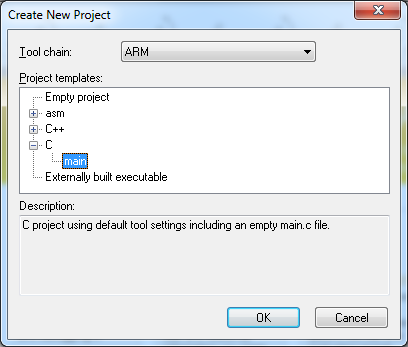
Для начала создадим пустой проект. IAR позволяет создать проекты на ASM, C и C++. Мы будем использовать C.
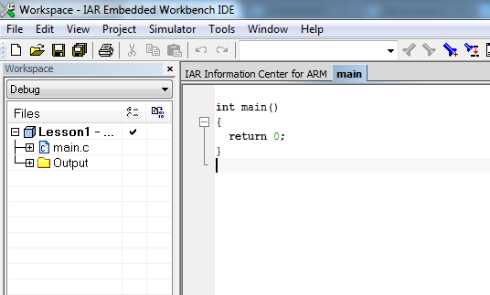
Перед нами появится пустой проект с main файлом.
Теперь необходимо настроить проект для начала работы с «нашим» МК и отладчиком. На плате STM32F4DISCOVERY установлен MK STM32F407VG . Его необходимо выбрать в свойствах проекта (General Options->Target->Device):
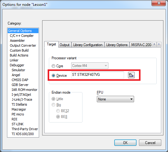
При выборе целевого программируемого процессора происходит загрузка его описания, что дает широкие возможности для отладки (об этом будет идти речь ниже). Кроме того, автоматически присоединяется конфигурационный файл с описанием доступного адресного пространства для линкера. Если будет необходимо, мы затронем тему конфигурационного файла линкера в следующих статьях.
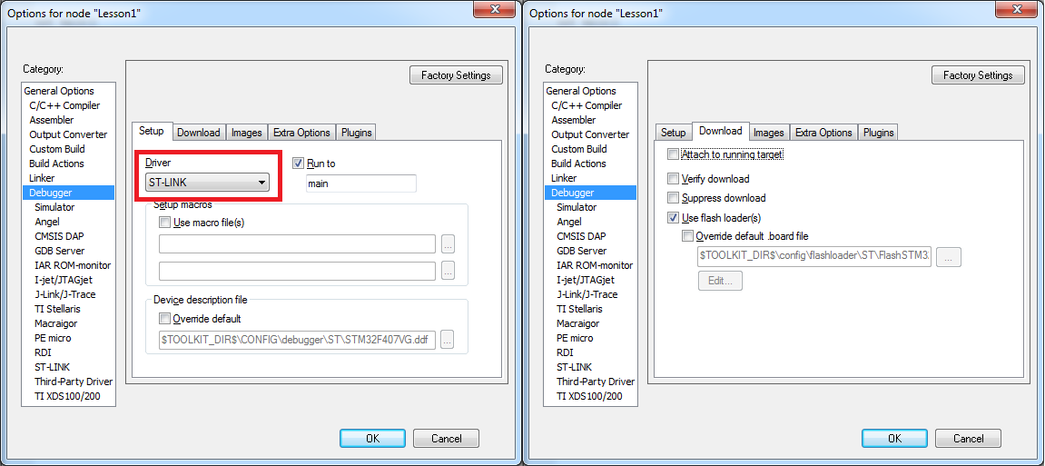
После этого необходимо настроить отладчик. Отладка программы происходит непосредственно «в железе». Производится это с помощью JTAG отладчика. Более подробнее ознакомиться с тем, как это происходит можно на Википедии. На плату STM32F4DISCOVERY интегрирован отладчик ST-LINK/V2. Для работы с отладчиком необходимо выбрать его драйвер в меню Debugger->Setup->Driver. Так же необходимо указать, что отладка должна производиться непосредственно в железе. Для этого необходимо поставить флаг Debugger->Download->Use flash loader(s)
Для тех, кто увидел слово Simulator
Теоретически, IAR позволяет отлаживать программы с использованием симулятора. Но я ни разу на практике не встречал его использования.
Теперь проект готов для работы (программирования, заливки и отладки).
«ТЗ» для первого проекта
Подведем промежуточный итог: МК и отладочная плата выбраны, проект подготовлен. Пора определиться с задачей.
Не будем отходить от классики. Первым проектом будет мигающий светодиод. Благо на плате их предостаточно.Что же это означает с точки зрения программирования? Первым делом необходимо изучить принципиальную схему демонстрационной платы и понять как «заводится» светодиод.
User manualдоступен на сайте производителя. В данном описании даже есть отдельный раздел про светодиоды на плате —4.4 LEDs. Для примера, будем использовать User LD3. Найдем его на схеме:
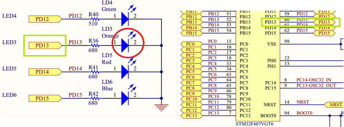
Простейший анализ схемы говорит о том, что для того, что бы «зажечь» светодиод необходимо на пин МК подать «1» (которая для данного МК соответствует 3.3В). Выключение производится подачей на этот пин «0». На схеме этот пин обозначается PD13 (это, наверное, самая важная информация из этого документа).
В итоге, мы можем написать «ТЗ» для нашей первой программы:
Программа для МК должна переводить состояние пина МК PD13 из состояния «0» в состояние «1» и обратно с некоторой периодичностью, различимой для человеческого глаза (важное замечание, если моргать светодиодом слишком часто глаз может этого не различить).
Прежде чем приступать к программированию, или немного теории
Прежде чем приступить к реализации нашего ТЗ, необходимо понять как производится управление МК.
Начнем с того, что любой МК включает ядро, память и периферийные блоки. Думаю, что с памятью пока все понятно. Упомяну лишь, в STM32 есть флеш память в которой хранится программа МК (в общем случае это не верное утверждение, программа может храниться во внешней энергонезависимой памяти, но пока это опустим) и другие данные, в том числе и пользовательские. Так же есть SRAM — оперативная память.
Ядро — часть микроконтроллера, осуществляющая выполнение одного потока команд. В нашем МК тип ядра — Cortex-M4. Ядро МК можно сравнить с процессором в ПК. Оно умеет только выполнять команды и передавать данные другим блокам (в этом сравнении не учитываются процессоры с интегрированными графическими ускорителями).
При этом производитель МК не разрабатывает ядро. Ядро покупается у компании ARM Limited. Главное отличие между различными МК — в периферии.
Периферийные блоки — блоки осуществляющие взаимодействие с «внешним миром» или выполняющие специфические функции, недоступные ядру МК. Современные МК (в том числе и STM32) содержат огромный спектр периферийных блоков. Периферийные блоки предназначены для решения различных задач, от считывания значения напряжения с аналогового входа МК до передачи данных внешним устройствам по шине SPI.
В отличии от ядра МК периферийные блоки не выполняют инструкции. Они лишь выполняют команды ядра. При этом участие ядра при выполнении команды не требуется.
Пример
В качестве примера можно привести блок UART, который предназначен для приема и передачи данных от МК внешним устройствам. От ядра необходимо лишь сконфигурировать блок и отдать ему данные для передачи. После этого ядро может дальше выполнять инструкции. На плечи же периферийного блока ложится управление соответствующим выводом МК для передачи данных в соответствии с протоколом. Периферийный блок сам переводит выход МК в необходимое состояние «0» или «1» в нужный момент времени, осуществляя передачу.
Взаимодействие ядра с периферийным блоком
Взаимодействие ядра МК с периферийным блоком осуществляется с помощью спецрегистров (есть еще взаимодействие через механизм прерываний и DMA, но об этом в следующих постах). С точки зрения ядра это просто участок памяти с определенным адресом, вот только на самом деле это не так. Запись данных в спецрегистр эквивалентна передаче команды или данных периферийному блоку. Считывание — получение данных от блока или считывание его состояния. Описание периферийных блоков и их спецрегистров занимает львиную долю описания МК.
ВАЖНО: После записи данных в спецрегистр и последующем чтении вы можете получить совершенно иные данные. Например, передача данных блоку UART для отправки, и считывание данных, полученных блоком от внешнего устройства, осуществляется с помощью одного и того же регистра.
Спецрегистры обычно разделены на битовые поля. Один (или несколько) бит управляют определенным параметром периферийного блока, обычно независимо. Например, разные биты одного регистра управляют состоянием разных выходов МК.
Вспоминаем С
Если вы гуру в языке C, то можете смело пропускать данный раздел. Он предназначен в первую очередь для тех, кого учили (или ктоучился сам) программировать для ПК. Опыт показывает, что люди часто не помнят важных команд. Здесь я вкратце напомню про побитовые операции и работу напрямую с памятью по ее адресу.
Запись данных по адресу в памяти
Предположим, что читая описание периферийного блока, мы поняли, что для его корректной работы необходимо записать в него число 0x3B. Адрес спецрегистра 0x60004012. Регистр 32-битный.
Если вы сразу не знаете как это сделать, попробую описать цепочку рассуждений для получения правильной команды.
Значение 0x60004012 есть не что иное, как значение указателя на ячейку памяти. Нужно именно это и указать в нашей программе, тоесть сделать преобразование типов согласно синтаксису языка C:
(unsigned long*)(0x60004012)Таким образом, у нас есть указатель на элемент. Теперь нужно в этот элемент записать необходимое значение. Делается это разыменовыванием указателя. Таким образом получаем правильную команду:
*(unsigned long*)(0x60004012) = 0x3B;Установка произвольных бит в 1
Предположим, что необходимо установить «1» в 7 и 1 биты по адресу 0x60004012, при этом не изменив значение всех остальных бит в регистре. Для этого необходимо использовать бинарную операцию |. Сразу приведу правильный ответ:
*(unsigned long*)(0x60004012) |= 0x82;Обратите внимание на 2 факта. Биты считаются с нулевого, а не с первого. Данная операция на самом деле занимает неменее 3 тактов — считывание значения, модификация, запись. Иногда это не допустимо, поскольку между считыванием и записью значение одного из бит, которые нам запрещено изменять, могло быть изменено периферийным блоком. Незабывайте про эту особенность, иначе могут полезть баги, которые крайне сложно отловить.
Установка произвольных бит в 0
Предположим, что необходимо установить «0» в 7 и 1 биты по адресу 0x60004012, при этом не изменив значение всех остальных бит в регистре. Для этого необходимо использовать бинарную операцию &. Сразу приведу правильный ответ:
*(unsigned long*)(0x60004012) &= 0xFFFFFF7D;Или его более простою запись (не переживайте за лишнюю операцию, компилятор все заранее посчитает даже при минимальной оптимизации):
*(unsigned long*)(0x60004012) &= (~0x82);Некоторые особенности программ для МК
Здесь я постараюсь описать некоторые особенности программ для МК, которые важно помнить. Вещи достаточно очевидные, но все же.
У программы нет конца
В отличии от большинства программ для ПК, программа для МК не должна заканчиваться, НИКОГДА! А что собственно должен будет делать МК после завершения вашей программы? Вопрос, практически, риторический. Поэтому не забываем убедиться в том, что вы не забыли вечный цикл. При желании, можно перевести МК в режим сна.
Пользуйтесь целочисленными переменными
Не смотря на то, что мы используем МК с ядром Cortex-M4, который аппаратно выполняет операции над числами с плавающей точкой, советую вам отказаться от их использования. В МК без поддержки таких операций время вычислений будет просто огромным.
Откажитесь от динамического выделения памяти
Это только совет. Причина проста — памяти мало. Я не раз встречался с библиотеками, в которых были «медленные утечки» памяти. Было очень неприятно, когда после нескольких недель стабильной работы МК зависал с ошибкой. Лучше заранее продумать архитектуру своей программы так, чтобы не пришлось использовать динамическое выделение памяти.
Если же все-таки хочется использовать — внимательно изучите работу менеджера памяти или пишите свой.
Приступаем к работе!
Работа над программой для МК всегда начинается с чтения документации. Для нашего МК Reference manual доступен на сайте производителя. Страниц много, но все читать пока не нужно. Как уже было сказано, большую часть документации составляет описание периферийных блоков и их регистров. Так же хочу обратить внимание на то, что этот Reference Manual написан не для одного МК, а для нескольких линеек. Это говорит о том, что код будет переносим при переходе на другие МК в этих линейках (если конечно не пытаться использовать периферийные блоки которых нет в используемом МК).
В первую очередь необходимо определиться с какими блоками предстоит работать. Для это достаточно изучит разделы Introduction и Main features.
Непосредственное управление состоянием пинов МК осуществляется с помощью блока GPIO. Как указано в документации в МК STM32 может быть до 11 независимых блоков GPIO. Различные периферийные блоки GPIO принято называть портами. Порты обозначаются буквам от A до K. Каждый порт может содержать до 16 пинов. Как мы отметили ранее, светодиод подключается к пину PD13. Это означает, что управление этим пином осуществляется периферийным блоком GPIO порт D. Номер пина 13.
Ни каких других периферийных блоков на это раз нам не понадобится.
Управление тактированием периферийных блоков
Для снижения электропотребления МК практически все периферийные блоки после включения МК отключены. Включение/выключение блока производится подачей/прекращением подачи тактового сигнала на его вход. Для корректной работы, необходимо сконфигурировать контроллер тактового сигнала МК, чтобы необходимому периферийному блоку поступал тактовый сигнал.
Важно:Периферийный блок не может начать работу сразу после включения тактового сигнала. Необходимо подождать несколько тактов пока он «запустится». Люди, использующие библиотеки для периферийных устройств, зачастую даже не знают об этой особенности.
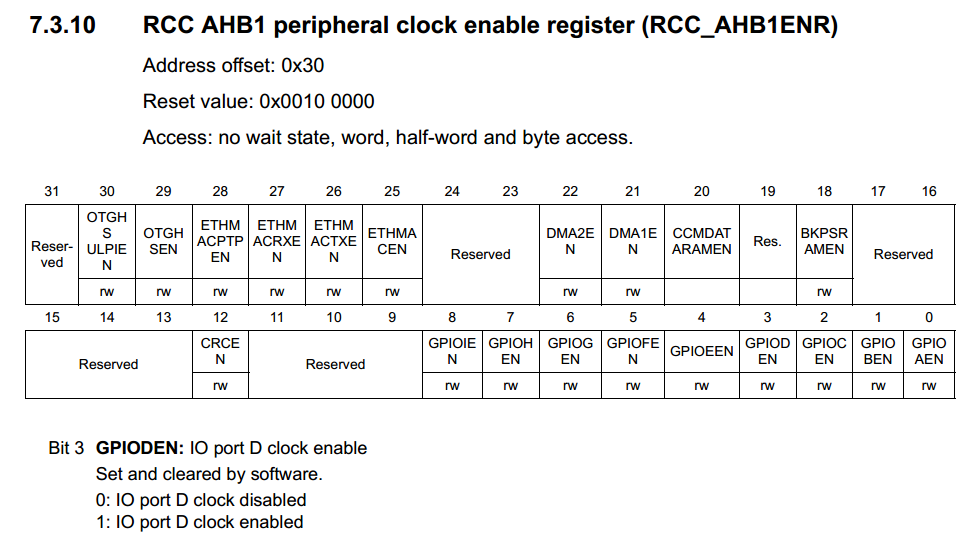
За включение тактирования периферийных блоков отвечают регистры RCC XXX peripheral clock enable register.На месте XXX могут стоять шины AHB1, AHB2, AHB3, APB1 и APB2. После внимательного изучения описания соответствующих регистров, можно сделать вывод о том, тактирование периферийного блока GPIOD включается установкой «1» в третий бит регистра RCC AHB1 peripheral clock enable register (RCC_AHB1ENR):
Теперь необходимо разобраться с тем, как узнать адрес самого регистра RCC_AHB1ENR.
Замечание: Описание системы тактирования МК STM32 достойно отдельной статьи. Если у читателей возникнет желание, я подробнее освещу этот раздел в одной из следующих статей.
Определение адресов спецрегистров
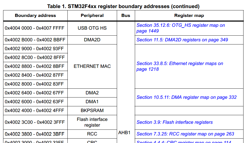
Определение адресов спецрегистров необходимо начинать с чтения раздела Memory map в Reference manual. Можно заметить, что каждому блоку выделен свой участок адресного пространства. Например, для блока RCC это участок 0x4002 3800 — 0x4002 3BFF:
Перейдя по ссылке к Register map блока RCC находим строчкку с интересующим нас регистром RCC_AHB1ENR:
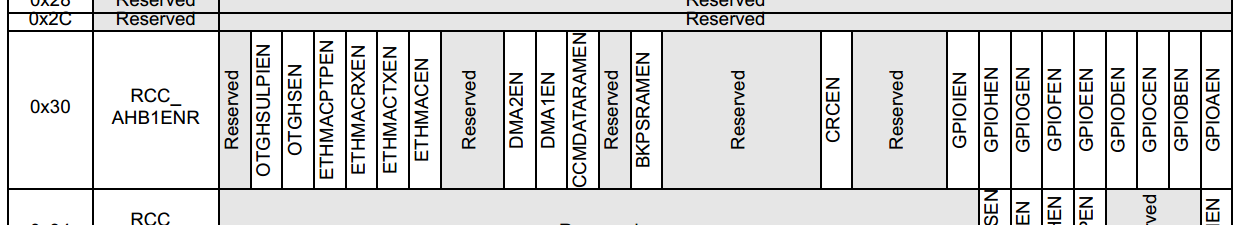
Для получения адреса регистра, необходимо к начальному значению адресного пространства блока RCC прибавить Addr. offset нужного регистра. Addres offset указывается и в описании регистра (см. скриншот выше).
В итоге, мы определили адрес регистра RCC_AHB1ENR — 0x4002 3830.
Блок GPIO
Для общего ознакомления с блоком GPIO я настоятельно рекомендую полностью прочитать соответствующий раздел Reference Manual. Пока можно не особо обращать внимание на Alternate mode. Это оставим на потом.
Сейчас же наша задача научиться управлять состоянием пинов МК. Перейдем сразу к описанию регистров GPIO.
Режим работы
В первую очередь необходимо установить режим работы 13 пина порта D как General purpose output mode, что означает что блок GPIO будет управлять состоянием пина МК. Управление режимом работы пинов МК производитсяс помощью регистра GPIO port mode register (GPIOx_MODER) (x = A..I/J/K):
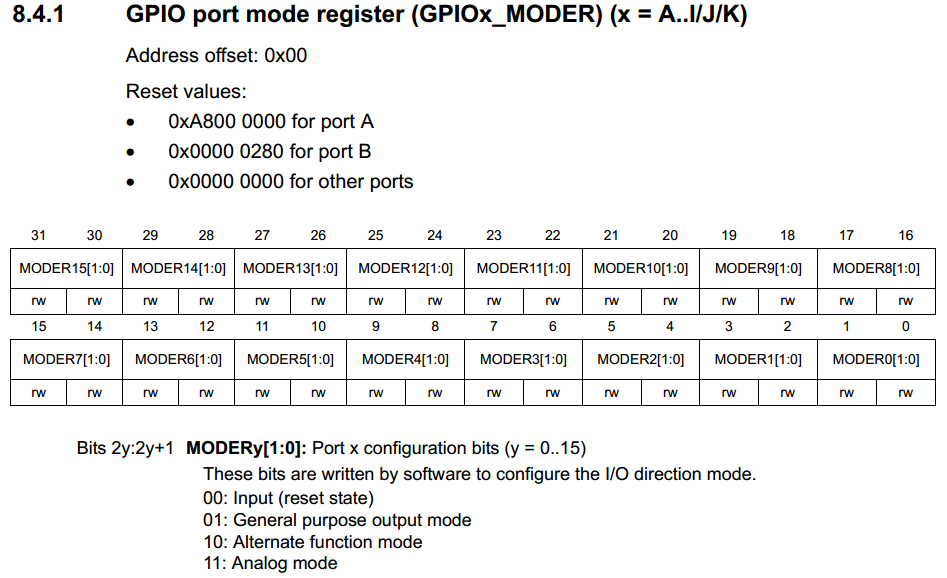
Как видно из описания для совершения требуемой нам настройки необходимо записать значение 01b в 26-27 биты регистра GPIOx_MODER. Адрес регистра можно определить тем же методом, что описан выше.
Настройка параметров работы выходных пинов порта GPIO
Блок GPIO позволяет применить дополнительные настройки для выходных пинов порта. Данные настройки производятся в регистрах:
- GPIO port output type register (GPIOx_OTYPER) — задается тип выхода push-pull или open-drain
- GPIO port output speed register (GPIOx_OSPEEDR) — задается скорость работы выхода
Мы не будем менять данных параметров, поскольку нас вполне устраивают значения по умолчанию.
Установка значения на пине МК
Наконец-то мы подошли к моменту управления состоянием выхода МК. Для утановки выходного значения на определенном пине МК есть два метода.
Используем регистр GPIO port bit set/reset register (GPIOx_BSRR)
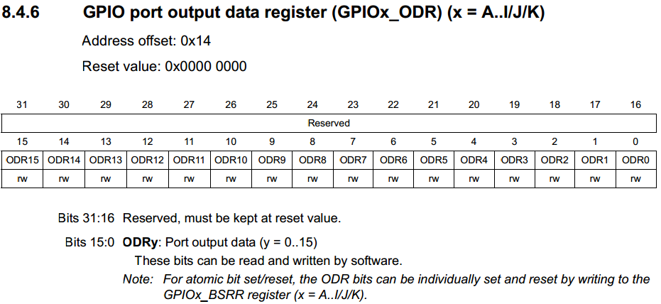
Запись «0» или «1» в биты 0-16 приводят к соответствующему изменению состояния пинов порта. Для того, чтобы установить определенное значение на выходе одного или нескольких пинов МК и не изменить состояния остальных, необходимо будет пользоваться операцией модификации отдельных бит. Такая операция выполняется не менее чем за 3 такта. Если же необходимо в часть битов записать 1, а в другие 0, то понадобится не менее 4 тактов. Данный метод предпочтительнее всего использовать для изменения состояния выхода на противоположное, если его изначальное состояние не известно.
GPIO port bit set/reset register (GPIOx_BSRR)

В отличии от предыдущего метода, запись 0 в любой из битов данного регистра не приведет ни к чему (да и вообще, все биты write-only!). Запись 1 в биты 0-15 приведет к установке «1» на соответствующем выходе МК. Запись 1 в биты 16-31 приведет к установке «0» на соответствующем выходе МК. Этот метод предпочтительнее предыдущего, если необходимо установить определенное значение на пине «МК», а не изменить его.
Зажигаем светодиод!
Найдя адреса всех необходимых регистров, можно написать программу, которая включает светодиод:
void main()
{
  //Enable port D clocking
  *(unsigned long*)(0x40023830) |= 0x8;

  //little delay for GPIOD get ready
  volatile unsigned long i=0;
  i++; i++; i++;
  i=0;

  //Set PD13 as General purpose output
  *(unsigned long*)(0x40020C00) = (*(unsigned long*)(0x40020C00)& (~0x0C000000)) | (0x04000000);

  //Turn LED ON!
  *(unsigned long*)(0x40020C14) |= 0x2000;

  while(1);
}
Можно компилировать (Project->Compile) и заливать (Project->Download->Download active application). Или запустить отладку (Project->Dpwnload and Debug) и начать выполнение (F5).
Светодиод загорелся!
Мигаем светодиодом
Мигание светодиода есть ни что иное, как попеременное включение и выключение с задержкой между этими действиями. Самый простой способ — поместить включение и выключение в вечный цикл, а между ними вставить задержку.
void main()
{
  //Enable port D clocking
  *(unsigned long*)(0x40023830) |= 0x8;

  //little delay for GPIOD get ready
  volatile unsigned long i=0;
  i++; i++; i++;
  i=0;

  //Set PD13 as General purpose output
  *(unsigned long*)(0x40020C00) = (*(unsigned long*)(0x40020C00)& (~0x0C000000)) | (0x04000000);

  while(1)
  {
    //Turn LED ON
    *(unsigned long*)(0x40020C14) |= 0x2000;
    //Delay
    for( i=0; i<1000000 ;++i );
    //Turn LED OFF
    *(unsigned long*)(0x40020C14) &= ~0x2000;
    //Delay
    for( i=0; i<1000000 ;++i );
  }
}
Значение 1000000 в задержке подобрано экспериментально так, чтобы период мигания светодиода был различим глазом, но и не был слишком велик.
Оптимизируем алгоритм
Минусом выбранного подхода миганием светодиодом является то, что ядро МК большую часть времени проводит в пустых циклах, хотя мог бы заниматься чем-нибудь полезным (в нашем примере других задач нет, но в будущем они появятся).
Для того, чтобы этого избежать, обычно используется счетчик циклов, а переключение состояние пина МК происходит при прохождении программы определенного числа циклов.
void main()
{
  //Enable port D clocking
  *(unsigned long*)(0x40023830) |= 0x8;

  //little delay for GPIOD get ready
  volatile unsigned long i=0;
  i++; i++; i++;
  i=0;

  //Set PD13 as General purpose output
  *(unsigned long*)(0x40020C00) = (*(unsigned long*)(0x40020C00)& (~0x0C000000)) | (0x04000000);

  while(1)
  {
    i++;

    if( !(i%2000000) )
    {
       //Turn LED ON
       *(unsigned long*)(0x40020С14) |= 0x2020;
    }
    else if( !(i%1000000) )
    {
      //Turn LED OFF
       *(unsigned long*)(0x40020С14) &= ~0x2000;
    }
  }
}
Но и тут не обойдется без проблем, с изменением количества команд выполняемых внутри цикла, будет меняться период мигания светодиодом (или период выполнения других команд в цикле). Но на данном этапе мы не можем с этим бороться.
Немного об отладке
IAR позволяет осуществлять отладку приложения непосредственно в железе. Все выглядит практически так же, как и отладка приложения для ПК. Есть режим пошагового выполнения, входа в функцию, просмотр значения переменных (В режиме отладки View->Watch->Watch1/4).
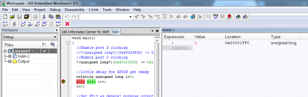
Но помимо этого, присутствует возможность просмотра значений регистров ядра, спецрегистров периферийных блоков (View->Register) и т.п.
Я настоятельно рекомендую ознакомиться с возможностями дебаггера во время изучения программирования МК.
Несколько слов в заключение
Возможно, многие скажут, что ручное прописывание адресов в программе это не правильно, поскольку производитель предоставляет файлы с определениями регистров и битовых полей, библиотеки для работы с периферией и другие инструменты, облегчающие жизнь разработчику. Я с этим полностью согласен, но все равно считаю, что первые шаги в программировании МК необходимо делать перекапывая документацию к вручную, самостоятельно определяя необходимые регистры и битовые поля. В дальнейшем этим можно не пользоваться, но уметь нужно обязательно.
Приведу лишь несколько причин для этого утверждения:
- В библиотеках от производителя иногда встречаются ошибки! Я один раз чуть не сорвал срок проекта из-за этого. Несколько раз перепаивал чип, думая, сто повредил кристалл при пайке (до этого такое случалось). А проблема заключалась в том, что в библиотеке был неверно прописан адрес спецрегистра. Обычно такое случается с МК или линейками МК только вышедшими на рынок.
- Библиотеки для работы спериферией некоторых производителей не реализуют всех возможностей периферийных блоков. Особенно этим грешилb Luminary Micro, которых в последствии выкупили TI. Приходилось писать инициализацию периферии вручную.
- Многие привыкают начинать программирование МК с изучения примеров. Я считаю, что сперва необходимо определиться с тем, что позволяет реализовать МК. Это можнопонять только прочитав документацию. Если чего-то нет в примерах, это не значит, что железоэто не поддерживает. Последний пример — аппаратная поддерка PTP STM32. В сети, конечно, можно кое-что найти, но это не входит в стандартный набор от производителя.
- Драйверы периферийных блоков некоторых производителей настолько не оптимизированы, что на переключение состояния пина средствами библиотеки тратится до 20 тактов. Это непозволительная роскошь для некоторых задач.
Спасибо всем, кто прочитал мой пост, получилось значительно больше чем я ожидал в начале.
Жду ваших комментариев и аргументированной критики. Если у прочитавших возникнет желание — постараюсь продолжить цикл статей. Возможно у кого-то есть идеи по поводу тем, которые стоило бы осветить — я был бы рад их услышать.
- Manuals
- Brands
- ARM Manuals
- Processor
- Cortex-M4
- Generic user manual
-
Contents
-
Table of Contents
-
Bookmarks
Quick Links
Cortex
-M4 Devices
™
Generic User Guide
Copyright © 2010 ARM. All rights reserved.
ARM DUI 0553A (ID121610)
Related Manuals for ARM Cortex-M4
Summary of Contents for ARM Cortex-M4
-
Page 1
Cortex -M4 Devices ™ Generic User Guide Copyright © 2010 ARM. All rights reserved. ARM DUI 0553A (ID121610) -
Page 2
This document is intended only to assist the reader in the use of the product. ARM shall not be liable for any loss or damage arising from the use of any information in this document, or any error or omission in such information, or any incorrect use of the product. -
Page 3: Table Of Contents
Cortex-M4 Devices Generic User Guide Preface About this book ………………….vi Feedback ……………………ix Chapter 1 Introduction About the Cortex-M4 processor and core peripherals ……….1-2 Chapter 2 The Cortex-M4 Processor Programmers model ………………..2-2 Memory model ………………….. 2-12 Exception model ………………..2-21 Fault handling ………………….
-
Page 4
Chapter 4 Cortex-M4 Peripherals About the Cortex-M4 peripherals …………….4-2 Nested Vectored Interrupt Controller …………… 4-3 System control block ………………..4-11 System timer, SysTick ………………. 4-33 Optional Memory Protection Unit …………….4-37 Floating Point Unit (FPU) ………………4-48 Appendix A Cortex-M4 Options Cortex-M4 implementation options ……………. -
Page 5
Preface This preface introduces the Cortex-M4 Devices Generic User Guide. It contains the following sections: • About this book on page vi • Feedback on page ARM DUI 0553A Copyright © 2010 ARM. All rights reserved. ID121610 Non-Confidential… -
Page 6: About This Book
Preface About this book This book is a generic user guide for devices that implement the ARM Cortex-M4 processor. Implementers of Cortex-M4 designs make a number of implementation choices, that can affect the functionality of the device. This means that, in this book: •…
-
Page 7: Typographical Conventions
< and > Enclose replaceable terms for assembler syntax where they appear in code or code fragments. For example: CMP Rn, <Rm|#imm> ARM DUI 0553A Copyright © 2010 ARM. All rights reserved. ID121610 Non-Confidential…
-
Page 8: Other Publications
• ARMv7-M Architecture Reference Manual (ARM DDI 0403). Other publications This guide only provides generic information for devices that implement the ARM Cortex-M4 processor. For information about your device see the documentation published by the device manufacturer. ARM DUI 0553A Copyright ©…
-
Page 9
Preface Feedback ARM welcomes feedback on this product and its documentation. Feedback on content If you have comments on content then send an e-mail to . Give: errata@arm.com • the title • the number, ARM DUI 0553A • the page numbers to which your comments apply •… -
Page 10: About The Cortex-M4 Processor And Core Peripherals
Chapter 1 Introduction This chapter introduces the Cortex-M4 processor and its features. It contains the following section: • About the Cortex-M4 processor and core peripherals on page 1-2. ARM DUI 0553A Copyright © 2010 ARM. All rights reserved. ID121610 Non-Confidential…
-
Page 11
Figure 1-1 Cortex-M4 implementation The Cortex-M4 processor is built on a high-performance processor core, with a 3-stage pipeline Harvard architecture, making it ideal for demanding embedded applications. The processor delivers exceptional power efficiency through an efficient instruction set and extensively… -
Page 12
Boolean data handling. The Cortex-M4 processor has an optional Memory Protection Unit (MPU) that permits control of individual regions in memory, enabling applications to utilize multiple privilege levels, separating and protecting code, data and stack on a task-by-task basis. -
Page 13: Programmers Model
It provides up to eight different regions, and an optional predefined background region. Floating-point Unit The Floating-Point Unit (FPU) provides IEEE754-compliant operations on single-precision, 32-bit, floating-point values. ARM DUI 0553A Copyright © 2010 ARM. All rights reserved. ID121610 Non-Confidential…
-
Page 14: Memory Model
Chapter 2 The Cortex-M4 Processor This chapter describes the Cortex-M4 processor. It contains the following sections: • Programmers model on page 2-2 • Memory model on page 2-12 • Exception model on page 2-21 • Fault handling on page 2-29 •…
-
Page 15
The Cortex-M4 Processor Programmers model This section describes the Cortex-M4 programmers model. In addition to the individual core register descriptions, it contains information about the processor modes and privilege levels for software execution and stacks. 2.1.1 Processor mode and privilege levels for software execution… -
Page 16
Describes access type during program execution in thread mode and Handler mode. Debug access can differ. b. An entry of Either means privileged and unprivileged software can access the register. ARM DUI 0553A Copyright © 2010 ARM. All rights reserved. ID121610 Non-Confidential… -
Page 17
For example: • read all of the registers using with the instruction • write to the APSR N, Z, C, V, and Q bits using with the instruction. APSR_nzcvq ARM DUI 0553A Copyright © 2010 ARM. All rights reserved. ID121610 Non-Confidential… -
Page 18
[28] Overflow flag [27] DSP overflow and saturation flag [26:20] Reserved [19:16] GE[3:0] Greater than or Equal flags. See SEL on page 3-70 for more information. [15:0] Reserved ARM DUI 0553A Copyright © 2010 ARM. All rights reserved. ID121610 Non-Confidential… -
Page 19
[31:27] Reserved. [26:25], [15:10] Interruptible-continuable instruction bits, see Interruptible-continuable instructions on page 2-7. [26:25], [15:10] Indicates the execution state bits of the instruction, see IT on page 3-122. ARM DUI 0553A Copyright © 2010 ARM. All rights reserved. ID121610 Non-Confidential… -
Page 20
The conditions for the instructions are either all the same, or some can be the inverse of others. See IT on page 3-122 for more information. Thumb state The Cortex-M4 processor only supports execution of instructions in Thumb state. The following can clear the T bit to 0: • instructions POP{PC •… -
Page 21
1 = prevents the activation of all exceptions except for NMI. The processor clears the FAULTMASK bit to 0 on exit from any exception handler except the NMI handler. ARM DUI 0553A Copyright © 2010 ARM. All rights reserved. ID121610 Non-Confidential… -
Page 22: Control Register
0 = no floating-point context active 1 = floating-point context active. The Cortex-M4 uses this bit to determine whether to preserve floating-point state when processing an exception. SPSEL Defines the currently active stack pointer: In Handler mode this bit reads as zero and ignores writes. The…
-
Page 23
The Cortex-M4 Processor In an OS environment, ARM recommends that threads running in Thread mode use the process stack and the kernel and exception handlers use the main stack. By default, Thread mode uses the MSP. To switch the stack pointer used in Thread mode to the PSP, either: •… -
Page 24
• Power management programming hints on page 2-34 • CMSIS functions on page 3-9 • Accessing the Cortex-M4 NVIC registers using CMSIS on page 4-4 • NVIC programming hints on page 4-9. ARM DUI 0553A Copyright © 2010 ARM. All rights reserved. -
Page 25
Optional bit-banding on page 2-16. The processor reserves regions of the Private Peripheral Bus (PPB) address range for core peripheral registers, see About the Cortex-M4 peripherals on page 4-2. 2.2.1 Memory regions, types and attributes The memory map and programming the optional MPU splits the memory map into regions. -
Page 26
Means that the memory system does not guarantee the ordering of the accesses. < Means that accesses are observed in program order, that is, A1 is always observed before A2. ARM DUI 0553A Copyright © 2010 ARM. All rights reserved. 2-13 ID121610 Non-Confidential… -
Page 27
Memory regions, types and attributes on page 2-12 for more information. The Code, SRAM, and external RAM regions can hold programs. However, ARM recommends that programs always use the Code region. This is because the processor has separate buses that enable instruction fetches and data accesses to occur simultaneously. -
Page 28
ISB on page 3-162. MPU programming Use a followed by an instruction or exception return to ensure that the new MPU configuration is used by subsequent instructions. ARM DUI 0553A Copyright © 2010 ARM. All rights reserved. 2-15 ID121610 Non-Confidential… -
Page 29
• is the starting address of the alias region Bit_band_base • is the number of the byte in the bit-band region that contains the targeted bit Byte_offset ARM DUI 0553A Copyright © 2010 ARM. All rights reserved. 2-16 ID121610 Non-Confidential… -
Page 30
0x00000001 Directly accessing a bit-band region Behavior of memory accesses on page 2-14 describes the behavior of direct byte, halfword, or word accesses to the bit-band regions. ARM DUI 0553A Copyright © 2010 ARM. All rights reserved. 2-17 ID121610 Non-Confidential… -
Page 31: Synchronization Primitives
2.2.7 Synchronization primitives The Cortex-M4 instruction set includes pairs of synchronization primitives. These provide a non-blocking mechanism that a thread or process can use to obtain exclusive access to a memory location. Software can use them to perform a guaranteed read-modify-write memory update sequence, or for a semaphore mechanism.
-
Page 32
1. The Cortex-M4 includes an exclusive access monitor, that tags the fact that the processor has executed a Load-Exclusive instruction. If the processor is part of a multiprocessor system, the system also globally tags the memory locations addressed by exclusive accesses by each processor. -
Page 33
__LDREXB (uint8_t *addr) STREX uint32_t __STREXW (uint32_t value, uint32_t *addr) STREXH uint32_t __STREXH (uint16_t value, uint16_t *addr) STREXB uint32_t __STREXB (uint8_t value, uint8_t *addr) CLREX void __CLREX (void) ARM DUI 0553A Copyright © 2010 ARM. All rights reserved. 2-20 ID121610 Non-Confidential… -
Page 34: Exception Model
HardFaults have a fixed priority of -1, meaning they have higher priority than any exception with configurable priority. ARM DUI 0553A Copyright © 2010 ARM. All rights reserved. 2-21 ID121610 Non-Confidential…
-
Page 35
-3, the highest Asynchronous 0x00000004 Asynchronous 0x00000008 HardFault 0x0000000C MemManage Synchronous Configurable 0x00000010 BusFault Synchronous when precise, Configurable 0x00000014 asynchronous when imprecise UsageFault Synchronous Configurable 0x00000018 7-10 Reserved ARM DUI 0553A Copyright © 2010 ARM. All rights reserved. 2-22 ID121610 Non-Confidential… -
Page 36: Fault Handling
The least-significant bit of each vector must be 1, indicating that the exception handler is Thumb code, see Thumb state on page 2-7. ARM DUI 0553A Copyright © 2010 ARM. All rights reserved. 2-23 ID121610 Non-Confidential…
-
Page 37: Exception Priorities
Configurable priority values are in the range 0-. This means that the Reset, HardFault, and NMI exceptions, with fixed negative priority values, always have higher priority than any other exception. ARM DUI 0553A Copyright © 2010 ARM. All rights reserved. 2-24 ID121610 Non-Confidential…
-
Page 38
ARM DUI 0553A Copyright © 2010 ARM. All rights reserved. 2-25 ID121610 Non-Confidential… -
Page 39
Figure 2-3 on page 2-27 shows the Cortex-M4 stack frame layout when floating-point state is preserved on the stack as the result of an interrupt or an exception. Note Where stack space for floating-point state is not allocated, the stack frame is the same as that of ARMv7-M implementations without an FPU. -
Page 40
If another higher priority exception occurs during exception entry, the processor starts executing the exception handler for this exception and does not change the pending status of the earlier exception. This is the late arrival case. ARM DUI 0553A Copyright © 2010 ARM. All rights reserved. 2-27 ID121610 Non-Confidential… -
Page 41
Return to Thread mode, exception return uses floating-point state from 0xFFFFFFE9 MSP and execution uses MSP after return. Return to Thread mode, exception return uses floating-point state from PSP 0xFFFFFFED and execution uses PSP after return. ARM DUI 0553A Copyright © 2010 ARM. All rights reserved. 2-28 ID121610 Non-Confidential… -
Page 42: Fault Types
BusFault Status Register on page 4-26 during exception unstacking UNSTKERR during instruction prefetch IBUSERR during lazy floating-point state preservation LSPERR Precise data bus error PRECISERR Imprecise data bus error IMPRECISERR ARM DUI 0553A Copyright © 2010 ARM. All rights reserved. 2-29 ID121610 Non-Confidential…
-
Page 43
Note Only Reset and NMI can preempt the fixed priority HardFault. A HardFault can preempt any exception other than Reset, NMI, or another HardFault. ARM DUI 0553A Copyright © 2010 ARM. All rights reserved. 2-30 ID121610 Non-Confidential… -
Page 44
Note If lockup state occurs from the NMI handler a subsequent NMI does not cause the processor to leave lockup state. ARM DUI 0553A Copyright © 2010 ARM. All rights reserved. 2-31 ID121610 Non-Confidential… -
Page 45: Power Management
The Cortex-M4 Processor Power management The Cortex-M4 processor sleep modes reduce power consumption. The sleep modes your device implements are implementation-defined. The modes can be one or both of the following: • sleep mode stops the processor clock • deep sleep mode stops the system clock and switches off the PLL and flash memory.
-
Page 46
When the WIC is enabled and the processor enters deep sleep mode, the power management unit in the system can power down most of the Cortex-M4 processor. This has the side effect of stopping the SysTick timer. When the WIC receives an interrupt, it takes a number of clock cycles to wakeup the processor and restore its state, before it can process the interrupt. -
Page 47
ISO/IEC C cannot directly generate the instructions. The CMSIS provides the following functions for these instructions: void __WFE(void) // Wait for Event void __WFI(void) // Wait for Interrupt ARM DUI 0553A Copyright © 2010 ARM. All rights reserved. 2-34 ID121610 Non-Confidential… -
Page 48
Chapter 3 The Cortex-M4 Instruction Set This chapter is the reference material for the Cortex-M4 instruction set description in a User Guide. The following sections give general information: • Instruction set summary on page 3-2 • CMSIS functions on page 3-9 •… -
Page 49: Instruction Set Summary
Compare Negative N,Z,C,V page 3-49 Rn, Op2 Compare N,Z,C,V page 3-49 Rn, Op2 Change Processor State, Disable Interrupts page 3-159 CPSID Change Processor State, Enable Interrupts page 3-159 CPSIE ARM DUI 0553A Copyright © 2010 ARM. All rights reserved. ID121610 Non-Confidential…
-
Page 50
N,Z,C page 3-44 ORN, ORNS {Rd,} Rn, Op2 Logical OR N,Z,C page 3-44 ORR, ORRS {Rd,} Rn, Op2 Pack Halfword page 3-108 PKHTB PKHBT {Rd,} Rn, Rm, Op2 ARM DUI 0553A Copyright © 2010 ARM. All rights reserved. ID121610 Non-Confidential… -
Page 51
Signed Halving Subtract and Add with Exchange page 3-56 SHSAX {Rd,} Rn, Rm Signed Halving Subtract 16 page 3-58 SHSUB16 {Rd,} Rn, Rm Signed Halving Subtract 8 page 3-58 SHSUB8 {Rd,} Rn, Rm ARM DUI 0553A Copyright © 2010 ARM. All rights reserved. ID121610 Non-Confidential… -
Page 52
Store Register Exclusive page 3-36 STREX Rd, Rt, [Rn, #offset] Store Register Exclusive Byte page 3-36 STREXB Rd, Rt, [Rn] Store Register Exclusive Halfword page 3-36 STREXH Rd, Rt, [Rn] ARM DUI 0553A Copyright © 2010 ARM. All rights reserved. ID121610 Non-Confidential… -
Page 53
Unsigned Multiply (32 x 32), 64-bit result page 3-93 UMULL RdLo, RdHi, Rn, Rm Unsigned Saturating Add 16 page 3-105 UQADD16 {Rd,} Rn, Rm Unsigned Saturating Add 8 page 3-105 UQADD8 {Rd,} Rn, Rm ARM DUI 0553A Copyright © 2010 ARM. All rights reserved. ID121610 Non-Confidential… -
Page 54
Floating-point Fused Multiply Accumulate page 3-135 VFMA.F32 {Sd,} Sn, Sm Floating-point Fused Negate Multiply Accumulate page 3-136 VFNMA.F32 {Sd,} Sn, Sm Floating-point Fused Multiply Subtract page 3-135 VFMS.F32 {Sd,} Sn, Sm ARM DUI 0553A Copyright © 2010 ARM. All rights reserved. ID121610 Non-Confidential… -
Page 55
VMOV Sd, Sm Copy ARM core register to single precision page 3-143 VMOV Sn, Rt Copy 2 ARM core registers to 2 single precision page 3-144 VMOV Sm, Sm1, Rt, Rt2 Copy ARM core register to scalar page 3-145 VMOV… -
Page 56: Cmsis Functions
The Cortex-M4 Instruction Set CMSIS functions ISO/IEC C code cannot directly access some Cortex-M4 instructions. This section describes intrinsic functions that can generate these instructions, provided by the CMSIS and that might be provided by a C compiler. If a C compiler does not support an appropriate intrinsic function, you might have to use inline assembler to access some instructions.
-
Page 57
Table 3-3 CMSIS functions to access the special registers (continued) Special register Access CMSIS function Read uint32_t __get_MSP (void) Write void __set_MSP (uint32_t TopOfMainStack) Read uint32_t __get_PSP (void) Write void __set_PSP (uint32_t TopOfProcStack) ARM DUI 0553A Copyright © 2010 ARM. All rights reserved. 3-10 ID121610 Non-Confidential… -
Page 58: About The Instruction Descriptions
Shift Operations on page 3-13 • Address alignment on page 3-17 • PC-relative expressions on page 3-17 • Conditional execution on page 3-18 • Instruction width selection on page 3-21. ARM DUI 0553A Copyright © 2010 ARM. All rights reserved. 3-11 ID121610 Non-Confidential…
-
Page 59
Bit[0] of any address you write to the PC with a , or instruction must be 1 for correct execution, because this bit indicates the required instruction set, and the Cortex-M4 processor only supports Thumb instructions. 3.3.3 Flexible second operand Many general data processing instructions have a flexible second operand. -
Page 60
And it copies the original bit[31] of the register into the left-hand bits of the result. See Figure 3-1 on page 3-14. ARM DUI 0553A Copyright © 2010 ARM. All rights reserved. 3-13 ID121610 Non-Confidential… -
Page 61
, to the left by places, into the left-hand bits of the result. And it sets the right-hand bits of the result to 0. See Figure 3-3 on page 3-15. ARM DUI 0553A Copyright © 2010 ARM. All rights reserved. 3-14 ID121610 Non-Confidential… -
Page 62
RRXS Operand2 MOVS MVNS , the carry flag is updated to bit[0] of the register ANDS ORRS ORNS EORS BICS ARM DUI 0553A Copyright © 2010 ARM. All rights reserved. 3-15 ID121610 Non-Confidential… -
Page 63
The Cortex-M4 Instruction Set Carry Flag Figure 3-5 RRX ARM DUI 0553A Copyright © 2010 ARM. All rights reserved. 3-16 ID121610 Non-Confidential… -
Page 64
An aligned access is an operation where a word-aligned address is used for a word, dual word, or multiple word access, or where a halfword-aligned address is used for a halfword access. Byte accesses are always aligned. The Cortex-M4 processor supports unaligned access only for the following instructions: • LDRT •… -
Page 65: Conditional Execution
CBNZ the result. This section describes: • The condition flags on page 3-19 • Condition code suffixes on page 3-19. ARM DUI 0553A Copyright © 2010 ARM. All rights reserved. 3-18 ID121610 Non-Confidential…
-
Page 66
C = 1 Higher or same, unsigned CS or HS C = 0 Lower, unsigned CC or LO N = 1 Negative N = 0 Positive or zero ARM DUI 0553A Copyright © 2010 ARM. All rights reserved. 3-19 ID121610 Non-Confidential… -
Page 67
; Skip next two instructions unless GT condition holds CMPGT R2, R3 ; If ‘greater than’, compare R2 and R3, setting flags MOVGT R4, R5 ; If still ‘greater than’, do R4 = R5 ARM DUI 0553A Copyright © 2010 ARM. All rights reserved. 3-20 ID121610 Non-Confidential… -
Page 68
; creates a 32-bit instruction even for a short branch ADDS.W R0, R0, R1 ; creates a 32-bit instruction even though the same ; operation can be done by a 16-bit instruction ARM DUI 0553A Copyright © 2010 ARM. All rights reserved. 3-21 ID121610 Non-Confidential… -
Page 69: Memory Access Instructions
LDR and STR, register offset on page 3-27 STR{type} Store Register with unprivileged access LDR and STR, unprivileged on page 3-29 STR{type}T Store Register Exclusive LDREX and STREX on page 3-36 STREX{type} ARM DUI 0553A Copyright © 2010 ARM. All rights reserved. 3-22 ID121610 Non-Confidential…
-
Page 70
SP and must not be PC. Condition flags This instruction does not change the flags. Examples R1, TextMessage ; Write address value of a location labelled as ; TextMessage to R1. ARM DUI 0553A Copyright © 2010 ARM. All rights reserved. 3-23 ID121610 Non-Confidential… -
Page 71
Specifies an offset from . If is omitted, the address is the contents of offset offset Specifies the additional register to load or store for two-word operations. ARM DUI 0553A Copyright © 2010 ARM. All rights reserved. 3-24 ID121610 Non-Confidential… -
Page 72
4 in the multiple of 4 in the multiple of 4 in the range −1020 to 1020 range −1020 to 1020 range −1020 to 1020 ARM DUI 0553A Copyright © 2010 ARM. All rights reserved. 3-25 ID121610 Non-Confidential… -
Page 73
; Store R0 to address in R8, and store R1 to ; a word 4 bytes above the address in R8, ; and then decrement R8 by 16. ARM DUI 0553A Copyright © 2010 ARM. All rights reserved. 3-26 ID121610 Non-Confidential… -
Page 74
1 for correct execution, and a branch occurs to this halfword-aligned address • if the instruction is conditional, it must be the last instruction in the IT block. ARM DUI 0553A Copyright © 2010 ARM. All rights reserved. 3-27 ID121610 Non-Confidential… -
Page 75
; to a word value and put it in R0 R0, [R1, R2, LSL #2] ; Stores R0 to an address equal to sum of R1 ; and four times R2. ARM DUI 0553A Copyright © 2010 ARM. All rights reserved. 3-28 ID121610 Non-Confidential… -
Page 76
; R4 to an address in R7, with unprivileged access LDRHT R2, [R2, #8] ; Load halfword value from an address equal to ; sum of R2 and 8 into R2, with unprivileged access. ARM DUI 0553A Copyright © 2010 ARM. All rights reserved. 3-29 ID121610 Non-Confidential… -
Page 77
In these instructions: • can be SP or PC only for word loads • must not be SP and must not be PC • must be different from Rt2. ARM DUI 0553A Copyright © 2010 ARM. All rights reserved. 3-30 ID121610 Non-Confidential… -
Page 78
R7, localdata ; Load a byte value from an address labelled ; as localdata, sign extend it to a word ; value, and put it in R7. ARM DUI 0553A Copyright © 2010 ARM. All rights reserved. 3-31 ID121610 Non-Confidential… -
Page 79
If the writeback suffix is specified, the value of — 4 * ( -1) is written back to ARM DUI 0553A Copyright © 2010 ARM. All rights reserved. 3-32 ID121610 Non-Confidential… -
Page 80
; LDMIA is a synonym for LDM STMDB R1!,{R3-R6,R11,R12} Incorrect examples R5!,{R5,R4,R9} ; Value stored for R5 is unpredictable R2, {} ; There must be at least one register in the list. ARM DUI 0553A Copyright © 2010 ARM. All rights reserved. 3-33 ID121610 Non-Confidential… -
Page 81
• if the instruction is conditional, it must be the last instruction in the IT block. Condition flags These instructions do not change the flags. ARM DUI 0553A Copyright © 2010 ARM. All rights reserved. 3-34 ID121610 Non-Confidential… -
Page 82
PUSH {R2,LR} ; Push R2 and the link-register onto the stack POP {R0,R6,PC} ; Pop r0,r6 and PC from the stack, then branch to the new PC. ARM DUI 0553A Copyright © 2010 ARM. All rights reserved. 3-35 ID121610 Non-Confidential… -
Page 83
Load-Exclusive and Store-Exclusive instruction to a minimum. Note The result of executing a Store-Exclusive instruction to an address that is different from that used in the preceding Load-Exclusive instruction is unpredictable. ARM DUI 0553A Copyright © 2010 ARM. All rights reserved. 3-36 ID121610 Non-Confidential… -
Page 84
STREXEQ R0, R1, [LockAddr] ; Try and claim the lock CMPEQ R0, #0 ; Did this succeed? ; No – try again ..; Yes – we have the lock. ARM DUI 0553A Copyright © 2010 ARM. All rights reserved. 3-37 ID121610 Non-Confidential… -
Page 85
Synchronization primitives on page 2-18 for more information. Condition flags This instruction does not change the flags. Examples CLREX ARM DUI 0553A Copyright © 2010 ARM. All rights reserved. 3-38 ID121610 Non-Confidential… -
Page 86: General Data Processing Instructions
SASX and SSAX on page 3-60 SASX Signed Subtract and Add with Exchange SASX and SSAX on page 3-60 SSAX Subtract with Carry ADD, ADC, SUB, SBC, and RSB on page 3-41 ARM DUI 0553A Copyright © 2010 ARM. All rights reserved. 3-39 ID121610 Non-Confidential…
-
Page 87
Unsigned Sum of Absolute Differences and Accumulate USADA8 on page 3-72 USADA8 Unsigned Subtract 16 USUB16 and USUB8 on page 3-73 USUB16 Unsigned Subtract 8 USUB16 and USUB8 on page 3-73 USUB8 ARM DUI 0553A Copyright © 2010 ARM. All rights reserved. 3-40 ID121610 Non-Confidential… -
Page 88
ADR on page 3-23. Note is equivalent to the syntax that uses the operand. is equivalent to the ADDW imm12 SUBW syntax that uses the operand. imm12 ARM DUI 0553A Copyright © 2010 ARM. All rights reserved. 3-41 ID121610 Non-Confidential… -
Page 89
0b00 calculation word-aligned. — If you want to generate the address of an instruction, you have to adjust the constant based on the value of the PC. ARM recommends that you use the instruction instead of with equal to the PC, because your assembler automatically calculates the correct constant for the instruction. -
Page 90
; subtract the least significant words SBCS R9, R2, R1 ; subtract the middle words with carry R2, R8, R11 ; subtract the most significant words with carry ARM DUI 0553A Copyright © 2010 ARM. All rights reserved. 3-43 ID121610 Non-Confidential… -
Page 91
N and Z flags according to the result • can update the C flag during the calculation of , see Flexible second operand on Operand2 page 3-12 • do not affect the V flag. ARM DUI 0553A Copyright © 2010 ARM. All rights reserved. 3-44 ID121610 Non-Confidential… -
Page 92
R9, R2, #0xFF00 ORREQ R2, R0, R5 ANDS R9, R8, #0x19 EORS R7, R11, #0x18181818 R0, R1, #0xab R7, R11, R14, ROR #4 ORNS R7, R11, R14, ASR #32 ARM DUI 0553A Copyright © 2010 ARM. All rights reserved. 3-45 ID121610 Non-Confidential… -
Page 93
0 to 31 shift length from 1 to 32 shift length from 1 to 31. Note is the preferred syntax for MOVS Rd, Rm LSLS Rd, Rm, #0 ARM DUI 0553A Copyright © 2010 ARM. All rights reserved. 3-46 ID121610 Non-Confidential… -
Page 94
R4, R5, #6 ; Logical shift right by 6 bits R4, R5, R6 ; Rotate right by the value in the bottom byte of R6 R4, R5 ; Rotate right with extend. ARM DUI 0553A Copyright © 2010 ARM. All rights reserved. 3-47 ID121610 Non-Confidential… -
Page 95
. The result value is 32 if no bits are set and zero if bit[31] is set. Restrictions Do not use SP and do not use PC. Condition flags This instruction does not change the flags. Examples R4,R9 CLZNE R2,R3 ARM DUI 0553A Copyright © 2010 ARM. All rights reserved. 3-48 ID121610 Non-Confidential… -
Page 96
Operand2 Condition flags These instructions update the N, Z, C and V flags according to the result. Examples R2, R9 R0, #6400 CMPGT SP, R7, LSL #2 ARM DUI 0553A Copyright © 2010 ARM. All rights reserved. 3-49 ID121610 Non-Confidential… -
Page 97
, performs a bitwise logical NOT operation on the Operand2 value, and places the result into Note instruction provides the same function as , but is restricted to using the MOVW imm16 operand. ARM DUI 0553A Copyright © 2010 ARM. All rights reserved. 3-50 ID121610 Non-Confidential… -
Page 98
0. Note Though it is possible to use as a branch instruction, ARM strongly recommends the use of instruction to branch for software portability to the ARM instruction set. Condition flags is specified, these instructions: •… -
Page 99
Condition flags This instruction does not change the flags. Examples MOVT R3, #0xF123 ; Write 0xF123 to upper halfword of R3, lower halfword ; and APSR are unchanged. ARM DUI 0553A Copyright © 2010 ARM. All rights reserved. 3-52 ID121610 Non-Confidential… -
Page 100
REVHS R3, R7 ; Reverse with Higher or Same condition RBIT R7, R8 ; Reverse bit order of value in R8 and write the result to R7. ARM DUI 0553A Copyright © 2010 ARM. All rights reserved. 3-53 ID121610 Non-Confidential… -
Page 101
; R1 and writes to corresponding halfword of R1. SADD8 R4, R0, R5 ; Adds bytes of R0 to the corresponding byte in R5 and writes ; to the corresponding byte in R4. ARM DUI 0553A Copyright © 2010 ARM. All rights reserved. 3-54 ID121610 Non-Confidential… -
Page 102
; writes halved result to corresponding halfword in R1 SHADD8 R4, R0, R5 ; Adds bytes of R0 to corresponding byte in R5 and ; writes halved result to corresponding byte in R4. ARM DUI 0553A Copyright © 2010 ARM. All rights reserved. 3-55 ID121610 Non-Confidential… -
Page 103
Restrictions Do not use SP and do not use PC Condition flags These instructions do not affect the condition code flags. ARM DUI 0553A Copyright © 2010 ARM. All rights reserved. 3-56 ID121610 Non-Confidential… -
Page 104
; of R3 and writes halved result to top halfword of R0 ; Adds top halfword of R5 to bottom halfword of R3 and ; writes halved result to bottom halfword of R0. ARM DUI 0553A Copyright © 2010 ARM. All rights reserved. 3-57 ID121610 Non-Confidential… -
Page 105
; of R1 and writes to corresponding halfword of R1 SHSUB8 R4, R0, R5 ; Subtracts bytes of R0 from corresponding byte in R5, ; and writes to corresponding byte in R4. ARM DUI 0553A Copyright © 2010 ARM. All rights reserved. 3-58 ID121610 Non-Confidential… -
Page 106
; and writes to corresponding halfword of R1 SSUB8 R4, R0, R5 ; Subtracts bytes of R5 from corresponding byte in ; R0, and writes to corresponding byte of R4. ARM DUI 0553A Copyright © 2010 ARM. All rights reserved. 3-59 ID121610 Non-Confidential… -
Page 107
Writes the signed result of the subtraction to the top halfword of the destination register. Restrictions Do not use SP and do not use PC Condition flags These instructions do not affect the condition code flags. ARM DUI 0553A Copyright © 2010 ARM. All rights reserved. 3-60 ID121610 Non-Confidential… -
Page 108
; and writes to bottom halfword of R7 ; Adds top halfword of R3 with bottom halfword of R2 and ; writes to top halfword of R7. ARM DUI 0553A Copyright © 2010 ARM. All rights reserved. 3-61 ID121610 Non-Confidential… -
Page 109
; APSR is updated but result is discarded TEQEQ R10, R9 ; Conditionally test if value in R10 is equal to ; value in R9, APSR is updated but result is discarded. ARM DUI 0553A Copyright © 2010 ARM. All rights reserved. 3-62 ID121610 Non-Confidential… -
Page 110
; writes to corresponding halfword of R1 UADD8 R4, R0, R5 ; Adds bytes of R0 to corresponding byte in R5 and writes ; to corresponding byte in R4. ARM DUI 0553A Copyright © 2010 ARM. All rights reserved. 3-63 ID121610 Non-Confidential… -
Page 111
Writes the unsigned result from the subtraction to the top halfword of the destination register. Restrictions Do not use SP and do not use PC Condition flags These instructions do not affect the condition code flags. ARM DUI 0553A Copyright © 2010 ARM. All rights reserved. 3-64 ID121610 Non-Confidential… -
Page 112
; and writes to bottom halfword of R7 ; Adds top halfword of R3 to bottom halfword of R2 and ; writes to top halfword of R7. ARM DUI 0553A Copyright © 2010 ARM. All rights reserved. 3-65 ID121610 Non-Confidential… -
Page 113
; and writes halved result to corresponding halfword in R7 UHADD8 R4, R0, R5 ; Adds bytes of R0 to corresponding byte in R5 and writes ; halved result to corresponding byte in R4. ARM DUI 0553A Copyright © 2010 ARM. All rights reserved. 3-66 ID121610 Non-Confidential… -
Page 114
Writes the halfword result of the addition to the bottom halfword of the destination register. Restrictions Do not use SP and do not use PC Condition flags These instructions do not affect the condition code flags. ARM DUI 0553A Copyright © 2010 ARM. All rights reserved. 3-67 ID121610 Non-Confidential… -
Page 115
; R3 and writes halved result to top halfword of R0 ; Adds top halfword of R5 to bottom halfword of R3 and ; writes halved result to bottom halfword of R0. ARM DUI 0553A Copyright © 2010 ARM. All rights reserved. 3-68 ID121610 Non-Confidential… -
Page 116
; R1 and writes halved result to corresponding halfword in ; R1 UHSUB8 R4, R0, R5 ; Subtracts bytes of R5 from corresponding byte in R0 and ; writes halved result to corresponding byte in R4. ARM DUI 0553A Copyright © 2010 ARM. All rights reserved. 3-69 ID121610 Non-Confidential… -
Page 117
These instructions do not change the flags. Examples SADD16 R0, R1, R2 ; Set GE bits based on result SEL R0, R0, R3 ; Select bytes from R0 or R3, based on GE. ARM DUI 0553A Copyright © 2010 ARM. All rights reserved. 3-70 ID121610 Non-Confidential… -
Page 118
; adds the differences and writes to R1 USAD8 R0, R5 ; Subtracts bytes of R5 from corresponding byte in R0, ; adds the differences and writes to R0. ARM DUI 0553A Copyright © 2010 ARM. All rights reserved. 3-71 ID121610 Non-Confidential… -
Page 119
; adds differences, adds value of R6, writes to R1 USADA8 R4, R0, R5, R2 ; Subtracts bytes of R5 from corresponding byte in R0 ; adds differences, adds value of R2 writes to R4. ARM DUI 0553A Copyright © 2010 ARM. All rights reserved. 3-72 ID121610 Non-Confidential… -
Page 120
; and writes to corresponding halfword in R1USUB8 R4, R0, R5 ; Subtracts bytes of R5 from corresponding byte in R0 and ; writes to the corresponding byte in R4. ARM DUI 0553A Copyright © 2010 ARM. All rights reserved. 3-73 ID121610 Non-Confidential… -
Page 121: Multiply And Divide Instructions
Unsigned Multiply with Accumulate (32×32+64), UMULL, UMLAL, SMULL, and SMLAL on page 3-93 UMLAL 64-bit result Unsigned Multiply (32×32), 64-bit result UMULL, UMLAL, SMULL, and SMLAL on page 3-93 UMULL ARM DUI 0553A Copyright © 2010 ARM. All rights reserved. 3-74 ID121610 Non-Confidential…
-
Page 122
, and places the least significant 32 bits of the result in The results of these instructions do not depend on whether the operands are signed or unsigned. ARM DUI 0553A Copyright © 2010 ARM. All rights reserved. 3-75 ID121610… -
Page 123
MULLT R2, R3, R2 ; Conditionally multiply, R2 = R3 x R2 R4, R5, R6, R7 ; Multiply with subtract, R4 = R7 — (R5 x R6) ARM DUI 0553A Copyright © 2010 ARM. All rights reserved. 3-76 ID121610 Non-Confidential… -
Page 124
SP and do not use PC. • must be different registers. RdHi RdLo Condition flags These instructions do not affect the condition code flags. ARM DUI 0553A Copyright © 2010 ARM. All rights reserved. 3-77 ID121610 Non-Confidential… -
Page 125
; top 32 bits to R6, and the bottom 32 bits to R3 UMLAL R2, R1, R3, R5 ; Multiplies R5 and R3, adds R1:R2, writes to R1:R2. ARM DUI 0553A Copyright © 2010 ARM. All rights reserved. 3-78 ID121610 Non-Confidential… -
Page 126
The bottom 16 bits of the 48-bit product are ignored. If overflow occurs during the addition of the accumulate value, the instruction sets the Q flag in the APSR. No overflow can occur during the multiplication. ARM DUI 0553A Copyright © 2010 ARM. All rights reserved. 3-79 ID121610 Non-Confidential… -
Page 127
; R3 to the result and writes top 32-bits to R10 SMLAWT R10, R2, R1, R5 ; Multiplies R2 with top halfword of R1, adds R5 ; and writes top 32-bits to R10. ARM DUI 0553A Copyright © 2010 ARM. All rights reserved. 3-80 ID121610 Non-Confidential… -
Page 128
SMLALDX R0, R2, R4, R6 ; Multiplies top halfword of R2 with bottom halfword ; of R4, multiplies bottom halfword of R2 with top ; halfword of R4, adds R6 and writes to R0. ARM DUI 0553A Copyright © 2010 ARM. All rights reserved. 3-81 ID121610 Non-Confidential… -
Page 129
Adds the resulting sign-extended 32-bit product to the 64-bit value in RdLo RdHi • Writes the 64-bit result of the multiplication and addition in RdLo RdHi The non-specified halfwords of the source registers are ignored. ARM DUI 0553A Copyright © 2010 ARM. All rights reserved. 3-82 ID121610 Non-Confidential… -
Page 130
; Multiplies top halfword in R5 with bottom ; halfword of R1, and bottom halfword of R5 with ; top halfword of R1, adds R8:R6 and writes to ; R8:R6. ARM DUI 0553A Copyright © 2010 ARM. All rights reserved. 3-83 ID121610 Non-Confidential… -
Page 131
RdLo • Writes the 64-bit result of the addition to the RdHi RdLo Restrictions In these instructions: • Do not use SP and do not use PC. ARM DUI 0553A Copyright © 2010 ARM. All rights reserved. 3-84 ID121610 Non-Confidential… -
Page 132
; Multiplies bottom halfword of R6 with top ; halfword of R2, multiplies top halfword of R6 ; with bottom halfword of R2, subtracts second from ; first, adds R6:R3, writes to R6:R3. ARM DUI 0553A Copyright © 2010 ARM. All rights reserved. 3-85 ID121610 Non-Confidential… -
Page 133
Writes the result of the subtraction in Restrictions In these instructions: • Do not use SP and do not use PC. Condition flags These instructions do not affect the condition code flags. ARM DUI 0553A Copyright © 2010 ARM. All rights reserved. 3-86 ID121610 Non-Confidential… -
Page 134
; subtracts R7, rounds and writes to R3 SMMLS R4, R5, R3, R8 ; Multiplies R5 and R3, extracts top 32 bits, ; subtracts R8, truncates and writes to R4. ARM DUI 0553A Copyright © 2010 ARM. All rights reserved. 3-87 ID121610 Non-Confidential… -
Page 135
; Multiplies R4 and R5, truncates top 32 bits ; and writes to R0 SMULLR R6, R2 ; Multiplies R6 and R2, rounds the top 32 bits ; and writes to R6. ARM DUI 0553A Copyright © 2010 ARM. All rights reserved. 3-88 ID121610 Non-Confidential… -
Page 136
; Multiplies bottom halfword of R4 with the bottom ; halfword of R5, adds multiplication of top halfword ; of R4 with top halfword of R5, writes to R0 ARM DUI 0553A Copyright © 2010 ARM. All rights reserved. 3-89 ID121610 Non-Confidential… -
Page 137
; Multiplies bottom halfword of R5 with top halfword of ; R3, subtracts multiplication of top halfword of R5 ; with bottom halfword of R3, writes to R4. ARM DUI 0553A Copyright © 2010 ARM. All rights reserved. 3-90 ID121610 Non-Confidential… -
Page 138
Writes the signed most significant 32 bits of the 48-bit result in the destination register. Restrictions In these instructions: • Do not use SP and do not use PC. • must be different registers. RdHi RdLo ARM DUI 0553A Copyright © 2010 ARM. All rights reserved. 3-91 ID121610 Non-Confidential… -
Page 139
; extracts top 32 bits and writes to R4 SMULWB R4, R5, R3 ; Multiplies R5 with the bottom halfword of R3, ; extracts top 32 bits and writes to R4. ARM DUI 0553A Copyright © 2010 ARM. All rights reserved. 3-92 ID121610 Non-Confidential… -
Page 140
Examples UMULL R0, R4, R5, R6 ; Unsigned (R4,R0) = R5 x R6 SMLAL R4, R5, R3, R8 ; Signed (R5,R4) = (R5,R4) + R3 x R8 ARM DUI 0553A Copyright © 2010 ARM. All rights reserved. 3-93 ID121610 Non-Confidential… -
Page 141
These instructions do not change the flags. Examples SDIV R0, R2, R4 ; Signed divide, R0 = R2/R4 UDIV R8, R8, R1 ; Unsigned divide, R8 = R8/R1 ARM DUI 0553A Copyright © 2010 ARM. All rights reserved. 3-94 ID121610 Non-Confidential… -
Page 142: Saturating Instructions
To clear the Q flag to 0, you must use the instruction, see MSR on page 3-164. To read the state of the Q flag, use the instruction, see MRS on page 3-163. ARM DUI 0553A Copyright © 2010 ARM. All rights reserved. 3-95 ID121610 Non-Confidential…
-
Page 143
; write it back to R7 USATNE R0, #7, R5 ; Conditionally saturate value in R5 as an ; unsigned 7 bit value and write it to R0. ARM DUI 0553A Copyright © 2010 ARM. All rights reserved. 3-96 ID121610 Non-Confidential… -
Page 144
; of R7 USAT16NE R0, #13, R5 ; Conditionally saturates the top and bottom ; halfwords of R5 as 13-bit values, writes to ; corresponding halfword of R0. ARM DUI 0553A Copyright © 2010 ARM. All rights reserved. 3-97 ID121610 Non-Confidential… -
Page 145
Do not use SP and do not use PC Condition flags These instructions do not affect the condition code flags. If saturation occurs, these instructions set the Q flag to 1. ARM DUI 0553A Copyright © 2010 ARM. All rights reserved. 3-98 ID121610 Non-Confidential… -
Page 146
QSUB8 R4, R2, R5 ; Subtracts bytes of R5 from the corresponding byte in ; R2, saturates to 8 bits, writes to corresponding byte of ; R4. ARM DUI 0553A Copyright © 2010 ARM. All rights reserved. 3-99 ID121610 Non-Confidential… -
Page 147
16, to the top halfword of the destination register. Restrictions Do not use SP and do not use PC Condition flags These instructions do not affect the condition code flags. ARM DUI 0553A Copyright © 2010 ARM. All rights reserved. 3-100 ID121610 Non-Confidential… -
Page 148
; R3, saturates to 16 bits, writes to top halfword of R0 ; Adds bottom halfword of R3 to top halfword of R5, ; saturates to 16 bits, writes to bottom halfword of R0. ARM DUI 0553A Copyright © 2010 ARM. All rights reserved. 3-101 ID121610 Non-Confidential… -
Page 149
; saturates to 32 bits, writes to R7 QDSUB R0, R3, R5 ; Subtracts R3 doubled and saturated to 32 bits ; from R5, saturates to 32 bits, writes to R0. ARM DUI 0553A Copyright © 2010 ARM. All rights reserved. 3-102 ID121610 Non-Confidential… -
Page 150
16, to the bottom halfword of the destination register. Restrictions Do not use SP and do not use PC Condition flags These instructions do not affect the condition code flags. ARM DUI 0553A Copyright © 2010 ARM. All rights reserved. 3-103 ID121610 Non-Confidential… -
Page 151
; saturates to 16 bits, writes to top halfword of R0 ; Adds bottom halfword of R4 to top halfword of R5 ; saturates to 16 bits, writes to bottom halfword of R0. ARM DUI 0553A Copyright © 2010 ARM. All rights reserved. 3-104 ID121610 Non-Confidential… -
Page 152
Saturates the results of the differences for each byte in the destination register to the unsigned range 0 ≤ x ≤ 2 −1, where x is 8. Restrictions Do not use SP and do not use PC ARM DUI 0553A Copyright © 2010 ARM. All rights reserved. 3-105 ID121610 Non-Confidential… -
Page 153
; halfword in R6 UQSUB8 R1, R5, R6 ; Subtracts bytes in R6 from corresponding byte of R5, ; saturates to 8 bits, writes to corresponding byte of R1. ARM DUI 0553A Copyright © 2010 ARM. All rights reserved. 3-106 ID121610 Non-Confidential… -
Page 154: Packing And Unpacking Instructions
Dual zero extend 8 bits to 16 and add SXT and UXT on page 3-117 UXTB16 Zero extend a halfword SXT and UXT on page 3-117 UXTH ARM DUI 0553A Copyright © 2010 ARM. All rights reserved. 3-107 ID121610 Non-Confidential…
-
Page 155
If shifted, the shifted value of the second operand is written to the bottom halfword of the destination register. Restrictions must not be SP and must not be PC. Condition flags This instruction does not change the flags. ARM DUI 0553A Copyright © 2010 ARM. All rights reserved. 3-108 ID121610 Non-Confidential… -
Page 156
R4, R0, R2 ASR #1 ; Writes R2 shifted right by 1 bit to bottom halfword ; of R4, and writes top halfword of R0 to top ; halfword of R4. ARM DUI 0553A Copyright © 2010 ARM. All rights reserved. 3-109 ID121610 Non-Confidential… -
Page 157
16 bits, and extracts bits [23:16] and UXTB16 zero extends to 16 bits. Restrictions Do not use SP and do not use PC. Condition flags These instructions do not affect the flags. ARM DUI 0553A Copyright © 2010 ARM. All rights reserved. 3-110 ID121610 Non-Confidential… -
Page 158
; of result, sign extends to 32 bits and writes to R4 UXTB R3, R10 ; Extracts lowest byte of value in R10, zero extends, and ; writes to R3. ARM DUI 0553A Copyright © 2010 ARM. All rights reserved. 3-111 ID121610 Non-Confidential… -
Page 159
Adds the signed or zero extended value to the word or corresponding halfword of Rn and writes the result in Rd. Restrictions Do not use SP and do not use PC. ARM DUI 0553A Copyright © 2010 ARM. All rights reserved. 3-112 ID121610 Non-Confidential… -
Page 160
; writes to R4 UXTAB R3, R4, R10 ; Extracts bottom byte of R10 and zero extends to 32 ; bits, adds R4, and writes to R3. ARM DUI 0553A Copyright © 2010 ARM. All rights reserved. 3-113 ID121610 Non-Confidential… -
Page 161: Bitfield Instructions
SBFX and UBFX on page 3-116 UBFX Zero extend a byte SXT and UXT on page 3-117 UXTB Zero extend a halfword SXT and UXT on page 3-117 UXTH ARM DUI 0553A Copyright © 2010 ARM. All rights reserved. 3-114 ID121610 Non-Confidential…
-
Page 162
; Clear bit 8 to bit 19 (12 bits) of R4 to 0 R9, R2, #8, #12 ; Replace bit 8 to bit 19 (12 bits) of R9 with ; bit 0 to bit 11 from R2. ARM DUI 0553A Copyright © 2010 ARM. All rights reserved. 3-115 ID121610 Non-Confidential… -
Page 163
UBFX R8, R11, #9, #10 ; Extract bit 9 to bit 18 (10 bits) from R11 and zero ; extend to 32 bits and then write the result to R8. ARM DUI 0553A Copyright © 2010 ARM. All rights reserved. 3-116 ID121610… -
Page 164
; 32 bits and write the result to R4. UXTB R3, R10 ; Extract lowest byte of the value in R10 and zero ; extend it, and write the result to R3. ARM DUI 0553A Copyright © 2010 ARM. All rights reserved. 3-117 ID121610 Non-Confidential… -
Page 165: Branch And Control Instructions
CBZ and CBNZ on page 3-121 If-Then IT on page 3-122 Table Branch Byte TBB and TBH on page 3-124 Table Branch Halfword TBB and TBH on page 3-124 ARM DUI 0553A Copyright © 2010 ARM. All rights reserved. 3-118 ID121610 Non-Confidential…
-
Page 166
−16 MB to +16 MB (inside IT block) Bcond label −16 MB to +16 MB BL{cond} label Any value in register BX{cond} Rm Any value in register BLX{cond} Rm ARM DUI 0553A Copyright © 2010 ARM. All rights reserved. 3-119 ID121610 Non-Confidential… -
Page 167
; Return from function call BXNE ; Conditionally branch to address stored in R0 ; Branch with link and exchange (Call) to a address stored ; in R0. ARM DUI 0553A Copyright © 2010 ARM. All rights reserved. 3-120 ID121610 Non-Confidential… -
Page 168
These instructions do not change the flags. Examples R5, target ; Forward branch if R5 is zero CBNZ R0, target ; Forward branch if R0 is not zero ARM DUI 0553A Copyright © 2010 ARM. All rights reserved. 3-121 ID121610 Non-Confidential… -
Page 169
PC-modifying instruction is permitted to branch to an instruction in an IT block. Restrictions The following instructions are not permitted in an IT block: • • CBNZ • CPSID CPSIE. ARM DUI 0553A Copyright © 2010 ARM. All rights reserved. 3-122 ID121610 Non-Confidential… -
Page 170
; Branch instruction can only be used in the last ; instruction of an IT block ; Next instruction is conditional R0, R0, R1 ; Syntax error: no condition code used in IT block ARM DUI 0553A Copyright © 2010 ARM. All rights reserved. 3-123 ID121610 Non-Confidential… -
Page 171
IT block, it must be the last instruction of the IT block. Condition flags These instructions do not change the flags. ARM DUI 0553A Copyright © 2010 ARM. All rights reserved. 3-124 ID121610 Non-Confidential… -
Page 172
((CaseB — BranchTable_H)/2) ; CaseB offset calculation ((CaseC — BranchTable_H)/2) ; CaseC offset calculation CaseA ; an instruction sequence follows CaseB ; an instruction sequence follows CaseC ; an instruction sequence follows ARM DUI 0553A Copyright © 2010 ARM. All rights reserved. 3-125 ID121610 Non-Confidential… -
Page 173: Floating-Point Instructions
Copy ARM core register to single precision VMOV ARM Core register to single precision on VMOV page 3-143 Copy 2 ARM core registers to 2 single precision VMOV Two ARM Core registers to two single precision VMOV on page 3-144 ARM DUI 0553A Copyright ©…
-
Page 174
Table 3-15 Floating-point instructions (continued) Mnemonic Brief description Copies between ARM core register to scalar VMOV ARM Core register to scalar on page 3-145 VMOV Copies between Scalar to ARM core register VMOV Scalar to ARM Core register on page 3-142… -
Page 175
Takes the absolute value of the operand floating-point register. Places the results in the destination floating-point register. Restrictions There are no restrictions. Condition flags The floating-point instruction clears the sign bit. Examples VABS.F32 S4, S6 ARM DUI 0553A Copyright © 2010 ARM. All rights reserved. 3-128 ID121610 Non-Confidential… -
Page 176
Places the results in the destination floating-point register. Restrictions There are no restrictions. Condition flags This instruction does not change the flags. Examples VADD.F32 S4, S6, S7 ARM DUI 0553A Copyright © 2010 ARM. All rights reserved. 3-129 ID121610 Non-Confidential… -
Page 177
FPSCR the ARM flags by a subsequent instruction, see VMRS on page 3-146. VMRS Examples VCMP.F32 S4, #0.0VCMP.F32 S4, S2 ARM DUI 0553A Copyright © 2010 ARM. All rights reserved. 3-130 ID121610 Non-Confidential… -
Page 178
The integer to floating-point operation uses the rounding mode specified by the FPSCR Restrictions There are no restrictions. Condition flags These instructions do not change the flags. ARM DUI 0553A Copyright © 2010 ARM. All rights reserved. 3-131 ID121610 Non-Confidential… -
Page 179
Round towards Zero fixed-point to floating-point operation uses the rounding mode. Round to Nearest Restrictions There are no restrictions. Condition flags These instructions do not change the flags. ARM DUI 0553A Copyright © 2010 ARM. All rights reserved. 3-132 ID121610 Non-Confidential… -
Page 180
Writes the result into the top or bottom half of a single-precision register, preserving the other half of the target register. Restrictions There are no restrictions. Condition flags These instructions do not change the flags. ARM DUI 0553A Copyright © 2010 ARM. All rights reserved. 3-133 ID121610 Non-Confidential… -
Page 181
Divides one floating-point value by another floating-point value. Writes the result to the floating-point destination register. Restrictions There are no restrictions. Condition flags These instructions do not change the flags. ARM DUI 0553A Copyright © 2010 ARM. All rights reserved. 3-134 ID121610 Non-Confidential… -
Page 182
Places the results in the destination register. The result of the multiply is not rounded before the addition. Restrictions There are no restrictions. Condition flags These instructions do not change the flags. ARM DUI 0553A Copyright © 2010 ARM. All rights reserved. 3-135 ID121610 Non-Confidential… -
Page 183
Places the result in the destination register. The result of the multiply is not rounded before the addition. Restrictions There are no restrictions. Condition flags These instructions do not change the flags. ARM DUI 0553A Copyright © 2010 ARM. All rights reserved. 3-136 ID121610 Non-Confidential… -
Page 184
, of the registers in size list • For the base address, the SP can be used. In the ARM instruction set, if is not specified can be used. • must contain at least one register. If it contains doubleword registers, it must not list contain more than 16 registers. -
Page 185
Specifies the label of the literal data item to be loaded. label Operation This instruction: • Loads a single extension register from memory, using a base address from an ARM core register, with an optional offset. Restrictions There are no restrictions. Condition flags These instructions do not change the flags. -
Page 186
Subtracts the products from the destination floating-point value. Places the results in the destination register. Restrictions There are no restrictions. Condition flags These instructions do not change the flags. ARM DUI 0553A Copyright © 2010 ARM. All rights reserved. 3-139 ID121610 Non-Confidential… -
Page 187
Is a floating-point constant. Operation This instruction copies a constant value to a floating-point register. Restrictions There are no restrictions. Condition flags These instructions do not change the flags. ARM DUI 0553A Copyright © 2010 ARM. All rights reserved. 3-140 ID121610 Non-Confidential… -
Page 188
Specifies the source register, for a singleword operation. Operation This instruction copies the contents of one floating-point register to another. Restrictions There are no restrictions Condition flags These instructions do not change the flags. ARM DUI 0553A Copyright © 2010 ARM. All rights reserved. 3-141 ID121610 Non-Confidential… -
Page 189
If x is 1, use upper half of doubleword register. Operation This instruction transfers: • one word from the upper or lower half of a doubleword floating-point register to an ARM core register. Restrictions Rt cannot be PC or SP. -
Page 190
The Cortex-M4 Instruction Set 3.11.16 VMOV ARM Core register to single precision Transfers a single-precision register to and from an ARM core register. Syntax VMOV{cond} Sn, Rt VMOV{cond} Rt, Sn where: Is an optional condition code, see Conditional execution on page 3-18. -
Page 191
• The contents of two consecutively numbered single-precision registers to two ARM core registers. • The contents of two ARM core registers to a pair of single-precision registers. Restrictions The restrictions are: • The floating-point registers must be contiguous, one after the other. -
Page 192
The Cortex-M4 Instruction Set 3.11.18 VMOV ARM Core register to scalar Transfers one word to a floating-point register from an ARM core register. Syntax VMOV{cond}{.32} Dd[x], Rt where: Is an optional condition code, see Conditional execution on page 3-18. cond Is an optional data size specifier. -
Page 193
Is an optional condition code, see Conditional execution on page 3-18. cond Specifies the destination ARM core register. This register can be R0-R14. Transfer floating-point flags to the APSR flags. APSR_nzcv Operation This instruction performs one of the following actions: •… -
Page 194
The Cortex-M4 Instruction Set 3.11.20 VMSR Move to floating-point System Register from ARM Core register. Syntax VMSR{cond} FPSCR, Rt where: Is an optional condition code, see Conditional execution on page 3-18. cond Specifies the general-purpose register to be transferred to the FPSCR. -
Page 195
This instruction: Multiplies two floating-point values. Places the results in the destination register. Restrictions There are no restrictions. Condition flags These instructions do not change the flags. ARM DUI 0553A Copyright © 2010 ARM. All rights reserved. 3-148 ID121610 Non-Confidential… -
Page 196
Places the results in a second floating-point register. The floating-point instruction inverts the sign bit. Restrictions There are no restrictions. Condition flags These instructions do not change the flags. ARM DUI 0553A Copyright © 2010 ARM. All rights reserved. 3-149 ID121610 Non-Confidential… -
Page 197
Multiplies together two floating-point register values. Writes the negation of the result to the destination register. Restrictions There are no restrictions. Condition flags These instructions do not change the flags. ARM DUI 0553A Copyright © 2010 ARM. All rights reserved. 3-150 ID121610 Non-Confidential… -
Page 198
This instruction loads multiple consecutive extension registers from the stack. Restrictions The list must contain at least one register, and not more than sixteen registers. Condition flags These instructions do not change the flags. ARM DUI 0553A Copyright © 2010 ARM. All rights reserved. 3-151 ID121610 Non-Confidential… -
Page 199
Stores multiple consecutive extension registers to the stack. Restrictions The restrictions are: • must contain at least one register, and not more than sixteen. list Condition flags These instructions do not change the flags. ARM DUI 0553A Copyright © 2010 ARM. All rights reserved. 3-152 ID121610 Non-Confidential… -
Page 200
Calculates the square root of the value in a floating-point register. • Writes the result to another floating-point register. Restrictions There are no restrictions. Condition flags These instructions do not change the flags. ARM DUI 0553A Copyright © 2010 ARM. All rights reserved. 3-153 ID121610 Non-Confidential… -
Page 201
If it contains doubleword registers it must not list contain more than 16 registers. • Use of the PC as is deprecated. Condition flags These instructions do not change the flags. ARM DUI 0553A Copyright © 2010 ARM. All rights reserved. 3-154 ID121610 Non-Confidential… -
Page 202
0-1020. can be omitted, meaning an offset of Operation This instruction: • Stores a single extension register to memory, using an address from an ARM core register, with an optional offset, defined in Restrictions The restrictions are: •… -
Page 203
Subtracts one floating-point value from another floating-point value. Places the results in the destination floating-point register. Restrictions There are no restrictions. Condition flags These instructions do not change the flags. ARM DUI 0553A Copyright © 2010 ARM. All rights reserved. 3-156 ID121610 Non-Confidential… -
Page 204: Miscellaneous Instructions
NOP on page 3-165 Send Event SEV on page 3-166 Supervisor Call SVC on page 3-167 Wait For Event WFE on page 3-168 Wait For Interrupt WFI on page 3-169 ARM DUI 0553A Copyright © 2010 ARM. All rights reserved. 3-157 ID121610 Non-Confidential…
-
Page 205
; Breakpoint with immediate value set to 0x3 (debugger can ; extract the immediate value by locating it using the PC) Note ARM does not recommend the use of the BKPT instruction with an immediate value set to 0xAB for any purpose other than Semi-hosting. ARM DUI 0553A Copyright ©… -
Page 206
CPSID f ; Disable interrupts and all fault handlers (set FAULTMASK) CPSIE i ; Enable interrupts and configurable fault handlers (clear PRIMASK) CPSIE f ; Enable interrupts and fault handlers (clear FAULTMASK) ARM DUI 0553A Copyright © 2010 ARM. All rights reserved. 3-159 ID121610 Non-Confidential… -
Page 207
Condition flags This instruction does not change the flags. Examples DMB ; Data Memory Barrier ARM DUI 0553A Copyright © 2010 ARM. All rights reserved. 3-160 ID121610 Non-Confidential… -
Page 208
The instruction completes when all explicit memory accesses before it complete. Condition flags This instruction does not change the flags. Examples DSB ; Data Synchronisation Barrier ARM DUI 0553A Copyright © 2010 ARM. All rights reserved. 3-161 ID121610 Non-Confidential… -
Page 209
Condition flags This instruction does not change the flags. Examples ISB ; Instruction Synchronisation Barrier ARM DUI 0553A Copyright © 2010 ARM. All rights reserved. 3-162 ID121610 Non-Confidential… -
Page 210
SP and must not be PC. Condition flags This instruction does not change the flags. Examples MRS R0, PRIMASK ; Read PRIMASK value and write it to R0 ARM DUI 0553A Copyright © 2010 ARM. All rights reserved. 3-163 ID121610 Non-Confidential… -
Page 211
This instruction updates the flags explicitly based on the value in Rn. Examples MSR CONTROL, R1 ; Read R1 value and write it to the CONTROL register ARM DUI 0553A Copyright © 2010 ARM. All rights reserved. 3-164 ID121610 Non-Confidential… -
Page 212
64-bit boundary. Condition flags This instruction does not change the flags. Examples NOP ; No operation ARM DUI 0553A Copyright © 2010 ARM. All rights reserved. 3-165 ID121610 Non-Confidential… -
Page 213
It also sets the local event register to 1, see Power management on page 2-32. Condition flags This instruction does not change the flags. Examples SEV ; Send Event ARM DUI 0553A Copyright © 2010 ARM. All rights reserved. 3-166 ID121610 Non-Confidential… -
Page 214
This instruction does not change the flags. Examples SVC #0x32 ; Supervisor Call (SVCall handler can extract the immediate value ; by locating it through the stacked PC) ARM DUI 0553A Copyright © 2010 ARM. All rights reserved. 3-167 ID121610 Non-Confidential… -
Page 215
0 and returns immediately. For more information see Power management on page 2-32. Condition flags This instruction does not change the flags. Examples WFE ; Wait for event ARM DUI 0553A Copyright © 2010 ARM. All rights reserved. 3-168 ID121610 Non-Confidential… -
Page 216
PRIMASK becomes pending • a Debug Entry request. Condition flags This instruction does not change the flags. Examples WFI ; Wait for interrupt ARM DUI 0553A Copyright © 2010 ARM. All rights reserved. 3-169 ID121610 Non-Confidential… -
Page 217
Chapter 4 Cortex-M4 Peripherals This chapter describes the ARM Cortex-M4 core peripherals. It contains the following sections: • About the Cortex-M4 peripherals on page 4-2 • Nested Vectored Interrupt Controller on page 4-3 • System control block on page 4-11 •… -
Page 218
Privileged Only privileged software can access the register. Unprivileged Both unprivileged and privileged software can access the register. ARM DUI 0553A Copyright © 2010 ARM. All rights reserved. ID121610 Non-Confidential… -
Page 219
Interrupt Priority Registers on page 4-7 0xE000E400 0x00000000 NVIC_IPR59 0xE000E4EF STIR Software Trigger Interrupt Register on page 4-8 Configurable 0xE000EF00 0x00000000 a. See the register description for more information. ARM DUI 0553A Copyright © 2010 ARM. All rights reserved. ID121610 Non-Confidential… -
Page 220
Cortex-M4 Peripherals 4.2.1 Accessing the Cortex-M4 NVIC registers using CMSIS CMSIS functions enable software portability between different Cortex-M profile processors. To access the NVIC registers when using CMSIS, use the following functions: Table 4-3 CMSIS access NVIC functions CMSIS function Description Enables an interrupt or exception. -
Page 221
Writing 1 to the ISPR bit corresponding to: • an interrupt that is pending has no effect • a disabled interrupt sets the state of that interrupt to pending. ARM DUI 0553A Copyright © 2010 ARM. All rights reserved. ID121610 Non-Confidential… -
Page 222
0 = interrupt is not pending 1 = interrupt is pending. Note Writing 1 to an ICPR bit does not affect the active state of the corresponding interrupt. ARM DUI 0553A Copyright © 2010 ARM. All rights reserved. ID121610 Non-Confidential… -
Page 223
[15:8] Priority, byte offset 1 [7:0] Priority, byte offset 0 Accessing the Cortex-M4 NVIC registers using CMSIS on page 4-4 for more information about the access to the interrupt priority array, which provides the software view of the interrupt priorities. -
Page 224
0x03 4.2.9 Level-sensitive and pulse interrupts A Cortex-M4 device can support both level-sensitive and pulse interrupts. Pulse interrupts are also described as edge-triggered interrupts. A level-sensitive interrupt is held asserted until the peripheral deasserts the interrupt signal. Typically this happens because the ISR accesses the peripheral, causing it to clear the interrupt request. -
Page 225
Cortex-M4 Peripherals Hardware and software control of interrupts The Cortex-M4 latches all interrupts. A peripheral interrupt becomes pending for one of the following reasons: • the NVIC detects that the interrupt signal is HIGH and the interrupt is not active •… -
Page 226
NVIC_SystemReset (void) The input parameter IRQn is the IRQ number, see Table 2-16 on page 2-22. For more information about these functions see the CMSIS documentation. ARM DUI 0553A Copyright © 2010 ARM. All rights reserved. 4-10 ID121610 Non-Confidential… -
Page 227: Auxiliary Control Register
• interruption of multi-cycle instructions. By default this register is set to provide optimum performance from the Cortex-M4 processor, and does not normally require modification. ARM DUI 0553A Copyright © 2010 ARM. All rights reserved.
-
Page 228
BusFaults to be precise BusFaults but decreases performance because any store to memory must complete before the processor can execute the next instruction. Note This bit only affects write buffers implemented in the Cortex-M4 processor. DISMCYCINT When set to 1, disables interruption of load multiple and store multiple instructions. This increases the interrupt latency of the processor because any LDM or STM must complete before the processor can stack the current state and enter the interrupt handler. -
Page 229
— whether there are preempted active exceptions — the exception number of the highest priority pending exception — whether any interrupts are pending. ARM DUI 0553A Copyright © 2010 ARM. All rights reserved. 4-13 ID121610 Non-Confidential… -
Page 230
Write: 0 = no effect 1 = changes SysTick exception state to pending. Read: 0 = SysTick exception is not pending 1 = SysTick exception is pending. ARM DUI 0553A Copyright © 2010 ARM. All rights reserved. 4-14 ID121610 Non-Confidential… -
Page 231
1 to the PENDSVSET bit and write 1 to the PENDSVCLR bit • write 1 to the PENDSTSET bit and write 1 to the PENDSTCLR bit. ARM DUI 0553A Copyright © 2010 ARM. All rights reserved. 4-15 ID121610 Non-Confidential… -
Page 232
Table 4-17 on page 4-17 for its attributes. To write to this register, you must write to the VECTKEY field, otherwise the processor 0x5FA ignores the write. ARM DUI 0553A Copyright © 2010 ARM. All rights reserved. 4-16 ID121610 Non-Confidential… -
Page 233
0 to this bit, otherwise behavior is Unpredictable. VECTRESET Reserved for Debug use. This bit reads as 0. When writing to the register you must write 0 to this bit, otherwise behavior is Unpredictable. ARM DUI 0553A Copyright © 2010 ARM. All rights reserved. 4-17 ID121610 Non-Confidential… -
Page 234
PRI_n[7:0] field showing the binary point. x denotes a group priority field bit, and y denotes a subpriority field bit. Note Determining preemption of an exception uses only the group priority field, see Interrupt priority grouping on page 2-25. ARM DUI 0553A Copyright © 2010 ARM. All rights reserved. 4-18 ID121610 Non-Confidential… -
Page 235
STIR by unprivileged software, see Software Trigger Interrupt Register on page 4-8. See the register summary in Table 4-12 on page 4-11 for the CCR attributes. ARM DUI 0553A Copyright © 2010 ARM. All rights reserved. 4-19 ID121610 Non-Confidential… -
Page 236
If this bit is set to 1, an unaligned access generates a UsageFault. Unaligned , and instructions always fault irrespective of LDRD STRD whether UNALIGN_TRP is set to 1. ARM DUI 0553A Copyright © 2010 ARM. All rights reserved. 4-20 ID121610 Non-Confidential… -
Page 237
[31:24] PRI_7 Reserved. [23:16] PRI_6 Priority of system handler 6, UsageFault [15:8] PRI_5 Priority of system handler 5, BusFault [7:0] PRI_4 Priority of system handler 4, MemManage ARM DUI 0553A Copyright © 2010 ARM. All rights reserved. 4-21 ID121610 Non-Confidential… -
Page 238
Table 4-23 SHPR3 register bit assignments Bits Name Function [31:24] PRI_15 Priority of system handler 15, SysTick exception [23:16] PRI_14 Priority of system handler 14, PendSV [15:0] Reserved. ARM DUI 0553A Copyright © 2010 ARM. All rights reserved. 4-22 ID121610 Non-Confidential… -
Page 239
Debug monitor active bit, reads as 1 if Debug monitor is active SVCALLACT SVCall active bit, reads as 1 if SVC call is active [6:4] Reserved. USGFAULTACT UsageFault exception active bit, reads as 1 if exception is active ARM DUI 0553A Copyright © 2010 ARM. All rights reserved. 4-23 ID121610 Non-Confidential… -
Page 240
MMFSR and BFSR with a halfword access to 0xE000ED28 • access the BFSR with a byte access to 0xE000ED29 • access the UFSR with a halfword access to 0xE000ED2A ARM DUI 0553A Copyright © 2010 ARM. All rights reserved. 4-24 ID121610 Non-Confidential… -
Page 241
When this bit is 1, the PC value stacked for the exception return points to the faulting instruction. The processor has not written a fault address to the MMAR. a. Only present in a Cortex-M4F device. ARM DUI 0553A Copyright © 2010 ARM. All rights reserved. 4-25 ID121610 Non-Confidential… -
Page 242
The processor does not adjust the SP from the failing return, does not performed a new save, and does not write a fault address to the BFAR. ARM DUI 0553A Copyright © 2010 ARM. All rights reserved. 4-26 ID121610… -
Page 243
1 only if it attempts to issue the faulting instruction. When the processor sets this bit is 1, it does not write a fault address to the BFAR. a. Only present in a Cortex-M4F device. ARM DUI 0553A Copyright © 2010 ARM. All rights reserved. 4-27 ID121610 Non-Confidential… -
Page 244
No coprocessor UsageFault. The processor does not support coprocessor instructions: 0 = no UsageFault caused by attempting to access a coprocessor 1 = the processor has attempted to access a coprocessor. ARM DUI 0553A Copyright © 2010 ARM. All rights reserved. 4-28 ID121610 Non-Confidential… -
Page 245
The UFSR bits are sticky. This means as one or more fault occurs, the associated bits are set to 1. A bit that is set to 1 is cleared to 0 only by writing 1 to that bit, or by a reset. ARM DUI 0553A Copyright © 2010 ARM. All rights reserved. 4-29 ID121610… -
Page 246
Function [31:0] ADDRESS When the MMARVALID bit of the MMFSR is set to 1, this field holds the address of the location that generated the MemManage fault ARM DUI 0553A Copyright © 2010 ARM. All rights reserved. 4-30 ID121610 Non-Confidential… -
Page 247
CFSR and SHPR1-SHPR3 it can use byte or aligned halfword or word accesses. The processor does not support unaligned accesses to system control block registers. ARM DUI 0553A Copyright © 2010 ARM. All rights reserved. 4-31 ID121610 Non-Confidential… -
Page 248
Software must follow this sequence because another higher priority exception might change the MMFAR or BFAR value. For example, if a higher priority handler preempts the current fault handler, the other fault might change the MMFAR or BFAR value. ARM DUI 0553A Copyright © 2010 ARM. All rights reserved. 4-32 ID121610 Non-Confidential… -
Page 249
Table 4-33 SysTick SYST_CSR register bit assignments Bits Name Function [31:17] Reserved. [16] COUNTFLAG Returns 1 if timer counted to 0 since last time this was read. [15:3] Reserved. ARM DUI 0553A Copyright © 2010 ARM. All rights reserved. 4-33 ID121610 Non-Confidential… -
Page 250
N processor clock cycles, use a RELOAD value of N-1. If the SysTick interrupt is required every 100 clock pulses, set RELOAD to 99. ARM DUI 0553A Copyright © 2010 ARM. All rights reserved. 4-34 ID121610… -
Page 251
If calibration information is not known, calculate the calibration value required from the frequency of the processor clock or external clock. ARM DUI 0553A Copyright © 2010 ARM. All rights reserved. 4-35 ID121610 Non-Confidential… -
Page 252
The SysTick counter reload and current value are not initialized by hardware. This means the correct initialization sequence for the SysTick counter is: Program reload value. Clear current value. Program Control and Status register. ARM DUI 0553A Copyright © 2010 ARM. All rights reserved. 4-36 ID121610 Non-Confidential… -
Page 253
• overlapping regions • export of memory attributes to the system. The memory attributes affect the behavior of memory accesses to the region. The Cortex-M4 MPU defines: • eight separate memory regions, 0-7 •… -
Page 254
Indicates the number of supported MPU data regions: = Eight MPU regions. 0x08 [7:1] Reserved. SEPARATE Indicates support for unified or separate instruction and date memory maps: 0 = unified. ARM DUI 0553A Copyright © 2010 ARM. All rights reserved. 4-38 ID121610 Non-Confidential… -
Page 255
Any access by unprivileged software that does not address an enabled memory region causes a MemManage fault. XN and Strongly-ordered rules always apply to the System Control Space regardless of the value of the ENABLE bit. ARM DUI 0553A Copyright © 2010 ARM. All rights reserved. 4-39 ID121610 Non-Confidential… -
Page 256
The MPU_RBAR defines the base address of the MPU region selected by the MPU_RNR, and can update the value of the MPU_RNR. See the register summary in Table 4-38 on page 4-38 for its attributes. ARM DUI 0553A Copyright © 2010 ARM. All rights reserved. 4-40 ID121610 Non-Confidential… -
Page 257
MPU_RASR is accessible using word or halfword accesses: • the most significant halfword holds the region attributes • the least significant halfword holds the region size and the region and subregion enable bits. ARM DUI 0553A Copyright © 2010 ARM. All rights reserved. 4-41 ID121610 Non-Confidential… -
Page 258
SIZE field values The SIZE field defines the size of the MPU memory region specified by the RNR. as follows: (SIZE+1) (Region size in bytes) = 2 ARM DUI 0553A Copyright © 2010 ARM. All rights reserved. 4-42 ID121610 Non-Confidential… -
Page 259
Cached memory, BB = outer policy, AA = inner policy. 0b1BB Table 4-46 on page 4-44 for the encoding of the AA Shareable and BB bits. a. The MPU ignores the value of this bit. ARM DUI 0553A Copyright © 2010 ARM. All rights reserved. 4-43 ID121610 Non-Confidential… -
Page 260
Simple code to configure one region: ; R1 = region number ; R2 = size/enable ; R3 = attributes ; R4 = address LDR R0,=MPU_RNR ; 0xE000ED98, MPU region number register ARM DUI 0553A Copyright © 2010 ARM. All rights reserved. 4-44 ID121610 Non-Confidential… -
Page 261
; R3 = size, attributes in one LDR R0, =MPU_RNR ; 0xE000ED98, MPU region number register STM R0, {R1-R3} ; Region Number, address, attribute, size and enable ARM DUI 0553A Copyright © 2010 ARM. All rights reserved. 4-45 ID121610 Non-Confidential… -
Page 262
When setting up the MPU, and if the MPU has previously been programmed, disable unused regions to prevent any previous region settings from affecting the new MPU setup. ARM DUI 0553A Copyright © 2010 ARM. All rights reserved. 4-46 ID121610… -
Page 263
DMA engine, the shareability attribute might be important. In these cases see the recommendations of the memory device manufacturer. ARM DUI 0553A Copyright © 2010 ARM. All rights reserved. 4-47 ID121610 Non-Confidential… -
Page 264
= Privileged access only. An unprivileged access generates a NOCP 0b01 fault. = Reserved. The result of any access is 0b10 Unpredictable = Full access. 0b11 [19:0] Reserved. Read as Zero, Write Ignore. ARM DUI 0553A Copyright © 2010 ARM. All rights reserved. 4-48 ID121610 Non-Confidential… -
Page 265
0 = Mode was not Thread Mode when the floating-point stack frame was allocated. 1 = Mode was Thread Mode when the floating-point stack frame was allocated. ARM DUI 0553A Copyright © 2010 ARM. All rights reserved. 4-49 ID121610 Non-Confidential… -
Page 266
Condition code flags. Floating-point comparison operations update these flags. Negative condition code flag. [30] Zero condition code flag. [29] Carry condition code flag. Overflow condition code flag. [28] [27] Reserved. ARM DUI 0553A Copyright © 2010 ARM. All rights reserved. 4-50 ID121610 Non-Confidential… -
Page 267
Input Denormal cumulative exception bit. Inexact cumulative exception bit. Underflow cumulative exception bit. Overflow cumulative exception bit. Division by Zero cumulative exception bit. Invalid Operation cumulative exception bit. ARM DUI 0553A Copyright © 2010 ARM. All rights reserved. 4-51 ID121610 Non-Confidential… -
Page 268
R1, R1, #(0xF << 20) ; Write back the modified value to the CPACR R1, [R0]; wait for store to complete ;reset pipeline now the FPU is enabled ARM DUI 0553A Copyright © 2010 ARM. All rights reserved. 4-52 ID121610 Non-Confidential… -
Page 269
Appendix A Cortex-M4 Options This appendix describes the configuration options for a Cortex-M4 processor implementation. It shows what features of a Cortex-M4 implementation are determined by the device manufacturer. It contains the following section: • Cortex-M4 implementation options on page A-2. -
Page 270: Floating-Point Instructions On Page
• the LSPERR bit in the BusFault Status Register (BFSR). Number of The implementer decides how many interrupts the Cortex-M4 implementation supports Cortex-M4 interrupts implementation supports, in the range 1-240. This affects: The range of IRQ values in Table 2-5 on page 2-6…
-
Page 271
Cortex-M4 Options Table A-1 Effects of the Cortex-M4 implementation options (continued) Option Description, and affected documentation Bit-banding The implementer decides whether bit-banding is implemented., see Optional bit-banding on page 2-16 Memory model on page 2-12. SysTick timer The SYST_CALIB register is implementation- defined. This can affect: •… -
Page 272
Glossary This glossary describes some of the terms used in technical documents from ARM. A mechanism that indicates to a processor that the value associated with a memory access is Abort invalid. An abort can be caused by the external or internal memory system as a result of attempting to access invalid instruction or data memory. -
Page 273
If the condition code flags indicate that the corresponding condition is true when the instruction starts executing, it executes normally. Otherwise, the instruction does nothing. The environment that each process operates in for a multitasking operating system. In ARM Context processors, this is limited to mean the physical address range that it can access in memory and the associated memory access permissions. -
Page 274
See also Big-endian memory. Load/store architecture A processor architecture where data-processing operations only operate on register contents, not directly on memory contents. ARM DUI 0553A Copyright © 2010 ARM. All rights reserved. Glossary-3 ID121610 Non-Confidential… -
Page 275
, and STRH STRB PUSH In a write-allocate cache, a cache miss on storing data causes a cache line to be allocated into Write-allocate (WA) the cache. ARM DUI 0553A Copyright © 2010 ARM. All rights reserved. Glossary-4 ID121610 Non-Confidential… -
Page 276
In a write-through cache, data is written to main memory at the same time as the cache is Write-through (WT) updated. ARM DUI 0553A Copyright © 2010 ARM. All rights reserved. Glossary-5 ID121610 Non-Confidential…
-
Contents
-
Table of Contents
-
Bookmarks
Quick Links
STM32F3 Series, STM32F4 Series, STM32L4 Series and
Introduction
This programming manual provides information for application and system-level software
developers. It gives a full description of the STM32 Cortex
model, instruction set and core peripherals.
The STM32F3 Series, STM32F4 Series, STM32L4 Series and STM32L4+ Series
®
Cortex
-M4 processor is a high performance 32-bit processor designed for the
microcontroller market. It offers significant benefits to developers, including:
• Outstanding processing performance combined with fast interrupt handling
• Enhanced system debug with extensive breakpoint and trace capabilities
• Efficient processor core, system and memories
• Ultra-low power consumption with integrated sleep modes
• Platform security
Reference documents
Available from STMicroelectronics web site www.st.com:
•
STM32F3 Series, STM32F4 Series, STM32L4 Series and STM32L4+ Series
datasheets
•
STM32F3 Series, STM32F4 Series, STM32L4 Series and STM32L4+ Series reference
manuals
October 2017
STM32L4+ Series Cortex
DocID022708 Rev 6
Programming manual
®
-M4 programming manual
®
-M4 processor programming
PM0214
1/260
www.st.com
1