- Manuals
- Brands
- Omicron Manuals
- Measuring Instruments
- CT Analyzer
- Getting started
-
Contents
-
Table of Contents
-
Bookmarks
Quick Links
CT Analyzer & CT SB2
Getting Started
Related Manuals for Omicron CT Analyzer
Summary of Contents for Omicron CT Analyzer
-
Page 1
CT Analyzer & CT SB2 Getting Started… -
Page 2
Getting Started with CT Analyzer & CT SB2 Manual Version: ENU 1132 03 01 This manual refers to version 4.50 of the CT Analyzer firmware and the CT Analyzer PC Toolset software. © OMICRON electronics GmbH 2016. All rights reserved. -
Page 3: Safety Symbols
Minor or moderate injury may occur if the appropriate safety instructions are not observed. NOTICE Equipment damage or loss of data possible Related documents The following documents complete the information covered in the Getting Started with CT Analyzer & CT SB2 Manual: Title Description CT Analyzer User Manual Contains information how to use and operate the CT Analyzer as well as safety instructions for working with the CT Analyzer.
-
Page 4: Safety Instructions
Before operating the CT Analyzer, read the safety instructions in this User Manual carefully. Do not turn on the CT Analyzer and do not operate the CT Analyzer without understanding the safety information in this manual. If you do not understand some safety instructions, contact OMICRON before proceeding.
-
Page 5: Operating The Measurement Setup
► Before putting the CT Analyzer into operation, check the equipment for visible damages. ► Use the CT Analyzer and its accessories only in a technically sound condition and when its use is in accordance with the safety regulations for the specific job site and application.
-
Page 6: Power Supply
The CT Analyzer and its accessories may be used only as described in this User Manual. Any other use is not in accordance with the regulations. The manufacturer and the distributor are not liable for damage resulting from improper usage.
-
Page 7
OMICRON test sets are subject to the EU Waste Electrical and Electronic Equipment Directive 2012/19/EU (WEEE directive). As part of our legal obligations under this legislation, OMICRON offers to take back the test set and ensure that it is disposed of by authorized recycling agents. -
Page 8
Parameters that are guessed by the CT Analyzer are marked by a question mark in the user interface of the CT-Object card prior to the test. To have a parameter guessed by the CT Analyzer, select the ? soft OMICRON… -
Page 9
The manufacturer and the distributor are not liable for damage resulting from improper usage. The user alone assumes all responsibility and risk. Note: The Quick Test function of the CT Analyzer and the CTA Quick Test PC tool cannot be used with the CT SB2 switch box. OMICRON… -
Page 10
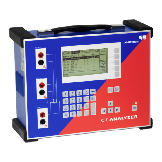
Getting Started with CT Analyzer & CT SB2 Functional components of the CT Analyzer 2.4.1 Overview Figure 2-1 provides an overview of the operating and display elements and the connectors of the CT Analyzer. Output Remote control interface Grounding Display… -
Page 11: Inputs And Outputs
Generator output. AC: 40V , 5A DC: 120V, 5A (15A peak Measurement input for secondary side of CT, 300V max. Prim Measurement input for primary side of CT, 30V max. Figure 2-2: Inputs and outputs of the CT Analyzer OMICRON…
-
Page 12
Any other behavior of the status LEDs than described above indicates an error. In this case, switch off the CT Analyzer. Do not touch any part of the test setup until the red LED is off and contact the OMICRON Technical Support (refer to chapter «Support» on page 29). -
Page 13: Functional Components Of The Ct Sb2
CT ANALYZER bonding connector Measurement input for primary Input and output terminals for connection to side of the CT. the CT Analyzer measurement inputs and generator output. OUT: Generator output for primary winding resistance measurement. A green LED lights up when the output is active.
-
Page 14: Setup And Connection
► Before putting the CT Analyzer into operation, check the test set for visible damages. ► When taking the CT Analyzer into operation, make sure that the air slots, the power switch and the power supply plug at the test set are not obstructed and that the test set can be easily disconnected from mains.
-
Page 15
► If possible, use the optional CT SB2 switch box for testing multi-ratio CTs. The CT Analyzer then automatically reduces the test voltage in a way that the maximum possible voltage within the measurement setup (i.e., the voltage occurring at the tap combination with the highest ratio) is limited to 200V. -
Page 16: Setting Up The Ct Analyzer
. Use a ground point as close as possible to the test object. 3. Connect the CT Analyzer to mains using the supplied power cord. Supply the CT Analyzer only from a power outlet that is equipped with protective ground (PE).
-
Page 17
3. Connect the black socket of CT Analyzer input «Prim» to the grounded side of the CT’s primary circuit and the red socket of this input to the open (ungrounded) side. -
Page 18
Getting Started with CT Analyzer & CT SB2 5. Connect the red «Output» socket and the red socket of input «Sec» of the CT Analyzer to the other (ungrounded) terminal on the secondary side of the CT. Prevent coupling of interferences into the primary circuit (e.g. by disconnecting the utility line, Utility line switching off the breaker, etc). -
Page 19: Basic Measurement Setup For Multi-Ratio Ct Testing
Basic measurement setup for multi-ratio CT testing Burden For information how to connect the communication link between the CT SB2 and the CT Analyzer, please refer to the CT SB2 User Manual. Figure 3-2: Basic measurement setup for multi-ratio CT testing (6 tap CT, no burden measurement, no…
-
Page 20: Mains Power Supply
Connector according to IEC 60320 Mains voltage 100 — 240V / 50/60Hz / 6A Instead of supplying the CT Analyzer from phase-neutral (L1-N, A-N), it may also be supplied from phase-phase (e.g. L1-L2, A-B). However, the nominal voltage must not exceed 240V Mains fuses…
-
Page 21: Winding Resistance Measurement Accuracy
• One terminal of the primary side of the CT is connected to PE. • The original measurement cables delivered by OMICRON for the CT Analyzer are used. • The CT under test is a CT with a non-gapped core.
-
Page 22: Compact Flash Card Interface
(e.g. running the CT Analyzer PC Toolset software) or to the optional CT SB2 switch box (for multi-ratio CT measurement). As of serial number JHxxxx or newer, the CT Analyzer is equipped with a USB interface and a RS232 interface.
-
Page 23: Usb Interface
Technical data of the CT Analyzer 4.7.1 RS232 interface The RS232 interface can be used to connect the CT Analyzer to a computer or to the optional CT SB2 switch box. 9-pole SUB-D connector, male Figure shows outside view onto the pins at the CT Analyzer!
-
Page 24: Environmental Conditions
Getting Started with CT Analyzer & CT SB2 Environmental conditions Table 4-11: Environmental conditions Characteristic Rating Operating temperature –10 … +50°C (14 … 122°F) Storage and transportation –25 … +70°C (–13 … 158°F) Max. altitude for operation 2000m Mechanical data…
-
Page 25
–20 … +70 °C (–4 … 158 °F) Max. altitude for operation 2000m Mechanical data Table 5-3: Mechanical data Characteristic Rating Weight 2.6kg (5.7lbs) without accessories Dimensions W x H x D 285 x 68 x 225mm (11.2 x 2.7 x 8.9″) OMICRON… -
Page 26
Getting Started with CT Analyzer & CT SB2 Standards Table 5-4: Standards EMC, safety IEC/EN 61326-1 (industrial electromagnetic environment) FCC subpart B of part 15, class A Safety IEC/EN/UL 61010-1 Other Shock IEC/EN 60068-2-27 (15 g/11 ms, half-sinusoid, 3 shocks in each axis) IEC/EN 60068-2-6 (frequency range 10 Hz…150 Hz, acceleration 2 g… -
Page 27
OMICRON Academy – learn more www.omicronenergy.com/academy Learn more about your product in one of the training courses offered by the OMICRON Academy. OMICRON electronics GmbH, Oberes Ried 1, 6833 Klaus, Austria, +43 59495 OMICRON… -
Page 28
ENU 1132 03 01…
This manual is also suitable for:
Ct sb2
CT Analyzer
Current transformer testing, calibration and assessment
Change cookie settings to load video. Allow marketing cookies.
Analyze your current transformer (CT) with the push of a button
How CT Analyzer works
- Injects low test signals into secondary side of the CT
- Determines the CT‘s equivalent circuit parameters
- Identifies all relevant CT performance parameters
- Displays all relevant parameters of the CT and its accuracy at different currents and burdens
- Evaluates the CT according to the selected standard
- Determines unknown CT nameplate parameters
- Demagnetizes the CT after the test.

Range of measurements
- Ratio and phase accuracy
- Winding resistance
- Excitation characteristics (knee points)
- Composite error (ALF, ALFi, FS, FSi, Vb)
- Burden impedance
- Transient CT classes and parameters (TPS, TPX, TPY and TPZ type CTs)
- Transient dimensioning factor (Ktd)
- If missing/unknown: CT type, class, ratio, knee point, power factor, nominal burden, operating burden, primary and secondary winding resistance
- Remanence and residual magnetism
- Immediate good/bad evaluation
Additional features:
- Simulate different burdens and currents
- Analyze the effect of CT saturation
- Measure VT ratio
- Multimeter
Key features
- Highest measurement accuracy: 0.02 % / 1 min when calibrating on site
- Very small and lightweight (< 8 kg / 17.4 lbs), easy to transport for on-site testing
- Automatic evaluation according to IEC, IEEE and to customized or local/national standards
- Short commissioning times (duration of the automatic test < 1min)
- Excellent workplace safety — Tests run at max. 120 V
- Integration into testing routines using Remote Interface Control
Download the latest software version for CT Analyzer in our Customer Portal.
Solution for:
Documents
Change cookie settings to load video. Allow marketing cookies.
Videos
Change cookie settings to load video. Allow marketing cookies.
CT Analyzer – the number one in current transformer testing
Change cookie settings to load video. Allow marketing cookies.
Efficient current transformer testing with OMICRON CT Analyzer
Change cookie settings to load video. Allow marketing cookies.
Methods for current transformer testing
Accessories
Training
June 29, 2023
Training Center Klaus,
Klaus,
Austria
Deutsch
CT Analyzer
October 11, 2023
Training Center New Delhi,
New Delhi,
India
English
CT Analyzer, VOTANO 100
October 17, 2023
Training Center Seongnam,
Seongnam,
South Korea
한국말
CT Analyzer, VOTANO 100
Get in touch
Need more details?
Get a quotation?
Request for a demo?
Contact us now
|
Detail Specifications: 1635/1635115-ct_analyzer.pdf file (12 Nov 2022) |
Accompanying Data:
Omicron CT Analyzer Measuring Instruments PDF Getting Started (Updated: Saturday 12th of November 2022 05:16:19 AM)
Rating: 4.4 (rated by 68 users)
Compatible devices: NA1-11, Dosimag, AUTOMIX, C-Probe 1, U1084A, Bode 100, ONE, Tip Etching Kit.
Recommended Documentation:
Text Version of Getting Started
(Ocr-Read Summary of Contents, UPD: 12 November 2022)
-
19, Omicron CT Analyzer OMICRON 19 Setup and connection 3.4 Basic measurement setup for multi-ratio CT testing Figure 3-2: Basic measurement setup for multi-ratio CT testing (6 tap CT, no burden measurement, no primary winding resistance measurement) WARNING Death or severe injury caused by high voltage or current possible Feeding test voltage to a CT can cause life-threatening voltages on other taps …
-
24, Getting Started with CT Analyzer & CT SB2 24 OMICRON 4.8 Environmental conditions 4.9 Mechanical data 4.10 Standards Table 4-11: Environmental conditions Characteristic Rating Operating temperature –10 … +50°C (14 … 122°F) Storage and transportation –25 … +70°C (–13 … 158°F) Max. altitude for operation 2000m Table 4-12: Mechanical data Ch…
-
27, Omicron CT Analyzer OMICRON 27 Support Support When you are working with our products we want to provide you with the greatest possible benefits. If you need any support, we are here to assist you! 24/7 Technical support – get support www.omicronenergy.com/support At our technical support hotline, you can reach well-educated technicians for all of your questions. Around the clock – competent and fr…
-
14, Getting Started with CT Analyzer & CT SB2 14 OMICRON 3 Setup and connection 3.1 General safety rules for connecting and operating the CT Analyzer Observe the following general safety rules and the safety instructions given in chapter 1 «Safety instructions» on page 4 when connecting and operating the CT Analyzer. The safety rules given here are supplemented by …
-
23, Omicron CT Analyzer OMICRON 23 Technical data of the CT Analyzer 4.7.1 RS232 interface The RS232 interface can be used to connect the CT Analyzer to a computer or to the optional CT SB2 switch box. Figure 4-1: Pin assignment for RS232 remote control interface Figure 4-2: Connection cable for RS232 remote control interface 4.7.2 USB interface The USB interface can be used to connect the CT Analyzer to a computer. C…
-
2, Getting Started with CT Analyzer & CT SB2 2 OMICRON Manual Version: ENU 1132 03 01 This manual refers to version 4.50 of the CT Analyzer firmware and the CT Analyzer PC Toolset software. © OMICRON electronics GmbH 2016. All rights reserved. This manual is a publication of OMICRON electronics GmbH. All rights including translation reserved. Reproduction of any kind, for exampl…
-
6, Getting Started with CT Analyzer & CT SB2 6 OMICRON 1.4 Power supply Supply the CT Analyzer only from a power outlet that is equipped with protective ground (PE). Instead of supplying the CT Analyzer from phase-neutral, it may also be supplied from phase-phase. However, the voltage must not exceed 240V AC. 1.5 Orderly measures The CT Analyzer User Manual or alternati…
-
7, OMICRON 7 Safety instructions Declaration of compliance (Canada) This Class A digital apparatus complies with Canadian ICES-003. Cet appareil numérique de la classe A est conforme à la norme NMB-003 du Canada. 1.8 Recycling This test set (including all accessories) is not intended for household use. At the end of its service life, do not dispose of the test set with household waste! F…
-
25, OMICRON 25 Technical data of the CT SB2 5 Technical data of the CT SB2 5.1 Specifications 5.2 Environmental conditions 5.3 Mechanical data Table 5-1: CT SB2 specifications Characteristic Rating Mains connection Connector according to IEC 60320 Mains voltage 100 — 240V AC / 50/60Hz / 0.2A Mains fuses 2 x T2.0AH 250V (high-breaking capacity wire fuse 5 x 20mm) Output voltage 0 — 120V Table 5-…
Recommended Instructions:
FAVORIT 535 i, F1 DSC, DVD-3610, 6280 — Cell Phone 10 MB


-
PŘEKLAD PŮVODNÍHO NÁVODU K POUŽITÍPREKLAD PÔVODNÉHO NÁVODU NA POUŽITIE — AZ ALKALMAZÁSI ORSZÁGOS UTASÍTÁSOK FORDÍTÁSA -PREVOD IZVIRNIH NAVODIL ZA UPORABO — TŁUMACZENIE ORYGINALNYCH INSTRUKCJI DO UŻYTKUÜBERSETZUNG DER URSPRÜNGLICHEN GEBRAUCHSANLEITUNG — PRIJEVOD PRETHODNE UPUTE ZA UPORABU TRANSLATION OF THE ORIGINAL OPERATING MANUAL — TRADUCTION DU MODE D’EMPLOI ORIGINAL …
LM060 59
-
Series DPMW LCD Digital Panel MetersSpecifications — Installation and Operating InstructionsBulletin E-90-DPMWDWYER INSTRUMENTS, INC. Phone: 219/879-8000 www.dwyer-inst.comP.O. BOX 373 • MICHIGAN CITY, INDIANA 46361, U.S.A. Fax: 219/872-9057 e-mail: [email protected]: 4-20 mA DC.Input Impedance: 300Ω nominal.Accuracy: ±(0.1% FS + 2 count).Backlight Power S …
DPMW Series 2
-
SKF TMEH 1Instructions for useMode d’emploiBedienungsanleitungInstrucciones de usoManuale d’instruzioniBruksanvisningGebruiksaanwijzingInstrucções de utilizaçãoBrugervejledningKäyttöohjeΟδηγίες χρήσης …
TMEH 1 92
Additional Information:
Popular Right Now:
Operating Impressions, Questions and Answers:
Table of Contents for Omicron CT Analyzer:
-
OMICRON 5 Safety instructions 1.3 Operating the measurement setup The safety instructions given here always apply when operating the CT Analyzer. They are supplemented by further notes and warnings applicable for specific actions only. Such specific notes and warnings are given where necessary in this user manual. In addition to the safety instructions given in this manual, always observe the applicable company- internal safety instructions and safety documents. In case of any pr
-
OMICRON 7 Safety instructions Declaration of compliance (Canada) This Class A digital apparatus complies with Canadian ICES-003. Cet appareil numérique de la classe A est conforme à la norme NMB-003 du Canada. 1.8 Recycling This test set (including all accessories) is not intended for household use. At the end of its service life, do not dispose of the test set with household waste! For customers in EU countries (incl. European Economic Area) OMICRON test sets are subject to the EU Waste Electric
-
OMICRON 9 Introduction key instead of specifying a value for this parameter. During the test, the CT Analyzer replaces the question mark by the value guessed. When using this function, please be aware that assessments performed with one or more guessed parameters may possibly differ from an assessment based on exact nameplate data. Absolutely reliable assessment is only guaranteed if all necessary CT data are specified prior to the test. For detailed information about the gue
-
OMICRON 11 Introduction 2.4.2 Inputs and outputs Figure 2-2: Inputs and outputs of the CT Analyzer WARNING Death or severe injury caused by high voltage possible As long as the red LED of the key is flashing, the output is active and lethal voltages can occur due to the high energy stored in external inductors. ► Do not touch the test object or the measurement leads while the red LED is flashing. ► Wait until the LED is off befo
-
OMICRON 21 Technical data of the CT Analyzer 4.4 Winding resistance measurement accuracy 4.5 Ratio and phase measurement accuracy The values given in the following table are only valid under the following conditions: • All utility lines to the primary side of the CT are disconnected. • One terminal of the primary side of the CT is connected to PE. • The original measurement cables delivered by OMICRON for the CT Analyzer are used. • The CT under test is a CT with a non-gapped core. • The knee point voltage according to IEEE
-
Getting Started with CT Analyzer & CT SB2 6 OMICRON 1.4 Power supply Supply the CT Analyzer only from a power outlet that is equipped with protective ground (PE). Instead of supplying the CT Analyzer from phase-neutral, it may also be supplied from phase-phase. However, the voltage must not exceed 240V AC. 1.5 Orderly measures The CT Analyzer User Manual or alternatively the e-book has always to be available on the site where the CT Analyzer is being used. The users of the CT Analyzer must read this manual before operating the dev
-
OMICRON 23 Technical data of the CT Analyzer 4.7.1 RS232 interface The RS232 interface can be used to connect the CT Analyzer to a computer or to the optional CT SB2 switch box. Figure 4-1: Pin assignment for RS232 remote control interface Figure 4-2: Connection cable for RS232 remote control interface 4.7.2 USB interface The USB interface can be used to connect the CT Analyzer to a computer. Communication via USB is considerably faster than communication via RS232. Figure 4-3: USB remote control interface (standard type B connector) 1nc 2 RxD (
-
Getting Started with CT Analyzer & CT SB2 26 OMICRON 5.4 Standards Table 5-4: Standards EMC, safety EMC IEC/EN 61326-1 (industrial electromagnetic environment) FCC subpart B of part 15, class A Safety IEC/EN/UL 61010-1 Other Shock IEC/EN 60068-2-27 (15 g/11 ms, half-sinusoid, 3 shocks in each axis) Vibration IEC/EN 60068-2-6 (frequency range 10 Hz…150 Hz, acceleration 2 g continuous (20 m/s 2 /65 ft/s 2 ), 20 c
-
Getting Started with CT Analyzer & CT SB2 22 OMICRON 4.6 Compact Flash card interface 4.7 Remote control interface The remote control interface of the CT Analyzer is exclusively intended to connect the CT Analyzer to a computer (e.g. running the CT Analyzer PC Toolset software) or to the optional CT SB2 switch box (for multi-ratio CT measurement). As of serial number JHxxxx or newer, the CT Analyzer is equipped with a USB interface and a RS232 interface. Note: The user has to select the interface to be used in the CT Analyzer settings before connecting the CT
-
Getting Started with CT Analyzer & CT SB2 12 OMICRON 2.4.3 I/0 key with status LEDs Red LED on the left, green LED on the right. I/0 key to start the test. During the boot process after switching the CT Analyzer on, both LEDs are on. The red LED goes off when the boot process is finished and the CT Analyzer is ready for operation. The green LED lights continuously to indicate that the equipment is operational and no voltage is applied to the test setup. The red LED flas
-
Getting Started with CT Analyzer & CT SB2 14 OMICRON 3 Setup and connection 3.1 General safety rules for connecting and operating the CT Analyzer Observe the following general safety rules and the safety instructions given in chapter 1 «Safety instructions» on page 4 when connecting and operating the CT Analyzer. The safety rules given here are supplemented by further notes and warnings applicable for specific actions only. Such specific notes and warnings are given where necessary in this m anual. ► Before putting the
-
Getting Started with CT Analyzer & CT SB2 10 OMICRON 2.4 Functional components of the CT Analyzer 2.4.1 Overview Figure 2-1 provides an overview of the operating and display elements and the connectors of the CT Analyzer. Figure 2-1: CT Analyzer overview Compact Flash card slot Remote control interface RS232 interface and USB interface for connecting the CT Analyzer to a PC Grounding terminal Keyboard with cursor keys and card selection keys Output Generator output Display with context-dependent keys («soft keys&quo
-
OMICRON 27 Support Support When you are working with our products we want to provide you with the greatest possible benefits. If you need any support, we are here to assist you! 24/7 Technical support – get support www.omicronenergy.com/support At our technical support hotline, you can reach well-educated technicians for all of your questions. Around the clock – competent and free of charge. Make use of our 24/7 technical support hotlines: Americas: +
-
Getting Started with CT Analyzer & CT SB2 20 OMICRON 4 Technical data of the CT Analyzer Guaranteed data are specified for an ambient temperature of 23°C ± 5° (73°F ± 9°), a power supply of 115/230V AC , and after a warm-up time longer than 15 minutes. Guaranteed data are valid for the period of one year after factory adjustment. 4.1 Mains power supply 4.2 Generator output 4.3 Measurement inputs Table 4-1: Mains
Questions, Opinions and Exploitation Impressions:
You can ask a question, express your opinion or share our experience of Omicron CT Analyzer device using right now.