-
Contents
-
Table of Contents
-
Bookmarks
Quick Links
JUMO CTI-750
Inductive Conductivity/Concentration and
Temperature Transmitter with Switch Contacts
Operating manual
20275616T90Z001K000
V3.00/EN/00488788
Related Manuals for JUMO CTI-750
Summary of Contents for JUMO CTI-750
-
Page 1
JUMO CTI-750 Inductive Conductivity/Concentration and Temperature Transmitter with Switch Contacts Operating manual 20275616T90Z001K000 V3.00/EN/00488788… -
Page 2
WARNING! A sudden failure of the instrument or of a sensor connected to it could result in dangerous overdosing. Please take suitable precautionary measures for this case. NOTE! All the nececssary settings are described in this manual. However, if any difficulties should arise during start-up, please do not carry out any unauthorized manipulations. -
Page 3: Table Of Contents
Contents Typographical conventions …………5 Warning signs ………………..5 Note signs ………………..5 General ………………6 Foreword ………………….6 Structure ………………….6 Inductive conductivity measurement ……..8 Range of Applications ………………8 Function …………………..9 Identifying the device version ……….10 Nameplate ………………..10 Order details ………………..11 Device description …………..
-
Page 4
Contents 10.1 Operating elements ………………41 10.2 Operation principle ………………43 10.3 Principle …………………45 10.4 Measurement mode ……………….46 10.5 Operating level ……………….46 10.6 Administrator level ………………54 10.7 Calibration level ………………56 10.8 The desalination function …………….57 Calibration …………….61 11.1 General …………………..61 11.2 Calibration of the relative cell constant …………61 11.3 Calibration of the temperature coefficient of the measurement solution …63… -
Page 5: Typographical Conventions
1 Typographical conventions Warning signs DANGER! This symbol is used when there may be danger to personnel if the instruc- tions are ignored or not followed correctly! CAUTION! This symbol is used when there may be damage to equipment or data if the instructions are ignored or not followed correctly! Note signs NOTE!
-
Page 6: General
2 General Foreword Please read the operating manual before you commission the device. Store the operating manual at a place that is accessible for all users at all times. NOTE! All the required settings are described in this manual. Should there be any difficulties nonetheless at the time of commissioning, we request you not to carry out any impermissible manipulations.
-
Page 7
2 General 2.2.2 Transmitter with separate sensor Example Transmitter (with or without graphics LC-display) Process connection Temperature sensor Inductive conductivity measuring probe… -
Page 8: Inductive Conductivity Measurement
3 Inductive conductivity measurement Range of Applications General The inductive measurement process allows a mostly maintenance-free acqui- sition of the specific conductivity even in difficult medium conditions. In con- trast to the conductive measurement process, problems like electrode replacement and polarization do not occur. Brief description The device is used for the measurement/control of the conductivity/concentra- tions of liquid media.
-
Page 9: Function
3 Inductive conductivity measurement Function of the transmitter The device is conceived for use at the location. A robust housing protects the electronics and the electrical connections from aggressive ambient influences (system of protection IP67). In the standard version, the device has one analog signal input for the conductivity/concentration and the temperature.
-
Page 10: Identifying The Device Version
4 Identifying the device version Nameplate On the transmitter The nameplate is affixed to the case. On the separate sensor The nameplate (flag tag) is affixed to the connecting cable. Contents The nameplate contains important information. This includes: Description Description on the Example nameplate Device type…
-
Page 11: Order Details
JUMO CTI-750 head transmitter in plastic housing, without display/keypad 202756/15 JUMO CTI-750 head transmitter in plastic housing, with display/keypad 202756/16 JUMO CTI-750 head transmitter in stainless steel housing, with display/keypad (2) Process connection Screw connection G 1 ½ A Screw connection G 2 A…
-
Page 12
202756/66 JUMO CTI-750 transmitter in stainless steel housing, with display/keypad (with sensor) cable length 10 m 202756/80 JUMO CTI-750 replacement sensor with 10 m cable for transmitter in plastic b, c housing (without transmitter) 202756/85 JUMO CTI-750 replacement sensor with 10 m cable for transmitter in stainless… -
Page 13
4 Identifying the device version Cell material PEEK Cell material PVDF Supply voltage 24 V AC Hygienic design The PC setup program is required for programming the device, see accessories. A calibration kit is absolutely essential for commissioning. If not available, please include in your order (see accessories). -
Page 14
4 Identifying the device version Accessories Type Part No. Flange DN 32, material: PP 00083375 Flange DN 50, material: PP 00083376 Weld-on threaded adapter DN 50, DIN 11851 00085020 Ring nut DN 50, DIN 11851 00343368 Ring nut SMS DN 2“, Mutter 00345162 M12 plug connector, 8-pole, straight, for assembly by user 00444307… -
Page 15: Device Description
5 Device description Technical data 5.1.1 Conductivity transmitter A/D converter Resolution 15 bits Sampling time 500 ms = 2 measurements/s Power supply For SELV and PELV circuit operation only. Standard 19 — 31 V DC (24 V DC nominal) Residual ripple <5 % Reverse polarity protection Extra code 844…
-
Page 16
5 Device description 5.1.2 Measuring ranges There is a choice of four different measuring ranges. Any one of these ranges can be activated by an external switch or by a PLC. NOTE! The overall accuracy is composed of transmitter accuracy + sensor accuracy. -
Page 17: Temperature Compensation
5 Device description 5.1.3 Temperature transmitters Temperature acquisition Manually, -20.0 to 25.0 to 150 °C or °F, or automatically Measuring range -20 — 150 °C or °F Characteristic linear ≤ 0.5 % of the measuring range Accuracy ≤ 0.1 %/K Ambient temperature effect Output signal 0 — 10 V or 10 — 0 V…
-
Page 18
5 Device description 5.1.5 Inductive conductivity sensor Measuring range Accuracy (as % of measuring range span) ≤ 1 % 0 — 500 µS/cm ≤ 1 % 0 — 1000 µS/cm ≤ 0,5 % 0 — 2000 µS/cm ≤ 0,5 % 0 — 5000 µS/cm ≤… -
Page 19: Mounting
6 Mounting General 6.1.1 Installation location The compatibility of the material with the measurement medium must be checked by the customer. Ensure easy accessibility for subsequent calibration. The fastening must be secure and low-vibration. Avoid direct sunlight. It is necessary to pay attention to a good flow through and around the sensor (3). When installing in a pipe, a minimum distance of 20 mm must be maintained from the sensor to the pipe wall.
-
Page 20: Dimensions Head Transmitter
6 Mounting Dimensions head transmitter 6.2.1 Process connections Version with process connection Version with process connection 108 = screw-in thread G 1 1/2 A 107 = screw-in thread G 1 1/4 A 110 = screw-in thread G 2 A 108 = screw-in thread G 1 1/2 A and extra code 767 110 = screw-in thread G 2 A and extra code 768…
-
Page 21
6 Mounting 2 (607) Version with process connection Version with process connection 607 = MK DN 50 606 = MK DN 40 608 = MK DN 65 607 = MK DN 50 609 = MK DN 80 608 = MK DN 65 and extra code 767 609 = MK DN 80 and extra code 768… -
Page 22
6 Mounting 1 (617) 2 (616) Version with process connection Version with process connection 616 = Clamp 2″ 617 = Clamp 2 1/2″ 617 = Clamp 2 1/2″ and extra code 768 and extra code 767 and 941 (retaining clip not included in delivery) (retaining clip not included in delivery) Version with process connection ®… -
Page 23
6 Mounting < 200Nm < 200Nm Version with process connection Version with process connection 690 = SMS 2″ 690 = SMS 2″ < 200Nm) < 200Nm) and extra code 767 and 941 and extra code 768 1 = stainless steel 1.4301 2 = PEEK 3 = PVDF… -
Page 24: The Device With Separate Sensor
6 Mounting The device with separate sensor 6.3.1 Operating unit Transmitter with separate sensor, in plastic housing with basic type extension 20 or 25 and electrical connection 82 ø110 6.3.2 Wall mounting…
-
Page 25: Process Connections
6 Mounting 6.3.3 Process connections Version with process connection Version with process connection 108 = screw-in thread G 1 1/2 A 107 = screw-in thread G 1 1/4 A 110 = screw-in thread G 2 A 108 = screw-in thread G 1 1/2 A and extra code 767 110 = screw-in thread G 2 A and extra code 768…
-
Page 26
6 Mounting 2 (607) Split version with process connection Split version with process connection 607 = MK DN 50 606 = MK DN40 608 = MK DN 65 607 = MK DN50 609 = MK DN 80 608 = MK DN65 and extra code 767 609 = MK DN80 (retaining clip not included in delivery) -
Page 27
6 Mounting 1 (617) 2 (616) Split version with process connection Split version with process connection 616 = Clamp 2″ 617 = Clamp 2 1/2″ 617 = Clamp 2 1/2″ and extra code 768 and extra code 767 (retaining clip not included in delivery) (retaining clip not included in delivery) 1 = stainless steel 1.4301 2 = PEEK… -
Page 28
6 Mounting Split version with process connection Split version with process connection 690 = SMS 2″ 690 = SMS 2″ and extra code 767 and extra code 768 (retaining clip not included in (retaining clip not included in < 200Nm) <… -
Page 29
6 Mounting ø18 ø100 ø165 Optional accessory DN 32 Flange Part no. 00083375 ø18 ø125 ø165 Split version with process connection 706 Optional accessory immersion model DN 50 Flange (pipe clips not included in delivery) Part no. 00083376 3 = PVDF 6 = PBT 7 = brass nickel plated EPDM… -
Page 30: Mounting Examples
6 Mounting Mounting examples Threaded pipe adapter Process connection 607, screwed pipe fitting DN 50, DIN 11851 (MK DN 50, milk cone), PEEK Ring nut DN 50, stainless steel 1.4301 Weld-on threaded pipe adaptor DN 50, DIN 11851, stainless steel 1.4404 (matching part for process connection 607) Tee DIN 11852, short, DN 50, stainless steel 1.4301 (to be provided by the plant operator;…
-
Page 31
6 Mounting Clamp Process connection 617, Clamp 2 1/2″, PEEK Clamping ring , stainless steel 1.4301 (to be provided by the plant operator; not supplied by device manufacturer) Tee, short, 2.5″ — 2″ similar to DIN 11852, and 2″ clamp adapter, stainless steel 1.4301 (to be provided by the plant operator;… -
Page 32
6 Mounting 6.4.1 Kit for pipe mounting NOTE! The pipe-mounting kit is also suitable for horizontal pipes. for type 202756, part no. 00515128… -
Page 33: Installation
7 Installation DANGER! The electrical connections may only be set up by technically qualified personnel. • When selecting the conductor material for the installation and for the elec- trical connections of the device, compliance is required with the specifica- tions of VDE 0100 «Regulations governing the installation of heavy-current systems with rated voltages below 1000 V»…
-
Page 34: General
7 Installation General Open the operating unit Unscrew the cover (1) Remove captive fastening screw (2) and carefully take out operating unit. Connect the cables SETUP CAUTION! For connecting the individual cores, pull out the threaded plug therminals (1) in the operating unit. Lead the connecting cables through the cable glands (2).
-
Page 35: Electrical Connection
7 Installation Wiring DANGER! In the case of devices with a separate sensor, for every instrument, the transmitter and the separate sensor are matched to one another at the factory. When connecting the components, ensure that the production number of the external sensor (on the flag tag on the connecting cable) is identical to the production number of the transmitter (on the nameplate).
-
Page 36
7 Installation ATTENTION! In devices with a separate sensor and M12 plug / socket connectors, the screw terminals in the device are painted over. Removing this paint voids the warranty! SETUP Terminal assignment Symbol Supply Supply (with reverse-polarity protection) Outputs Analog signal output: conductivity/concentration (electrically isolated) -
Page 37
7 Installation Terminal assignment Symbol Binary inputs Binary input E1 Binary input E2 7.2.2 Transmitter with electrical connection 83 (M12 plug-and-socket connection) Head transmitter Connector I Power supply and actual value output for conductivity/concentration M12 flush-type connector, 5-pin Blanking plug Connector II Actual value output for temperature, and binary input and switching outputs M12 flush-type connector, 8-pin… -
Page 38
7 Installation ATTENTION! In devices with a separate sensor and M12 plug / socket connectors, the screw terminals in the device are painted over. Removing this paint voids the warranty! Supply Connector Assignment Symbol Supply (with reverse-polarity protection) Outputs Analog signal output: conductivity/concentration (electrically isolated) Analog signal output:… -
Page 39: Setup-Program
8 Setup-Program Function Configurable parameters With the optional Setup program that is available, the transmitter can be com- fortably matched to the requirements. • Setting the measurement range and the measurement range limits. • Setting the behavior of the outputs in case of overshooting of the measure- ment range.
-
Page 40: Commissioning
9 Commissioning CAUTION! The measuring transmitters are checked in the factory for flawless operabil- ity and shipped ready for operation. Head transmitter or transmitter with separate sensor Install the device, see «Mounting», page 19. Connect the device, see «Installation», page 33. DANGER! In the case of devices with a separate sensor (base type supplementation (2) 66), for every instrument, the transmitter and the separate sensor are…
-
Page 41: Operation
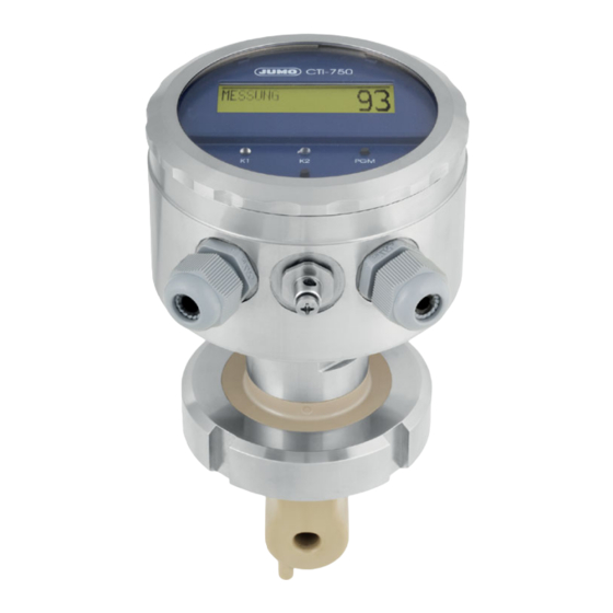
10 Operation 10.1 Operating elements Graphical LC-display, background lit up. , confirm inputs, select menu. , interrupt inputs without saving/interrupt calibration. EXIT One menu-level back. , increase numerical value/forward the selection. , decrease numerical value/forward the selection. LEDs «K1″/»K2» indicate the status of the switching outputs. In normal operation, the LED flows when the corresponding switching output is active.
-
Page 42
10 Operation LC-Display (11) (10) Output K1 is active Output K2 is active Binary input 1 is triggered Binary input 2 is triggered Keyboard is locked Device status (hints) • Alarm (e.g. overrange • Calib. flashing (calibration timer • Calib (customer calibration enabled) Output mode •… -
Page 43: Operation Principle
10 Operation 10.2 Operation principle 10.2.1 Operating in levels Measurement mode, see chapter 10.4 «Measurement mode», page 46 OPERATOR LEVEL, see chapter 10.5 «Operating level», page 46 INPUT CONDUCTIVITY MEASUREMENT RANGE 1…4 TEMP.COMPENSATION TEMP.COEFFICIENT 1…4 REFERENCE TEMPERATURE REL.CELL CONSTANT MOUNTING FACTOR CONCENTR.MEASUREMENT CONCENTR.RANGE OFFSET…
-
Page 44
10 Operation DEVICE DATA LANGUAGE CONTRAST LIGHTING LCD INVERSE ADMINISTR.-LEVEL, see chapter 10.6 «Administrator level», page 54 Password PARAMETER-LEVEL, see chapter 10.6.1 «Parameter level», page 55 INPUT CONDUCTIVITY. OUTPUT CONDUCTIVITY INPUT TEMPERATURE OUTPUT TEMPERATURE OUTPUT BINARY 1 OUTPUT BINARY 2 INPUT BINARY 1 INPUT BINARY 2 DESALINATION FUNCTION… -
Page 45: Principle
10 Operation 10.3 Principle Level…
-
Page 46: Measurement Mode
10 Operation 10.4 Measurement mode Depiction In the measurement mode, the conductivity compensated to the reference temperature, or the concentration, and the temperature of the measurement medium are displayed. MEASUREMENT -> Measurement mode 20.5 °C -> Temperature of the measurement medium 203 mS/cm ->…
-
Page 47
10 Operation 10.5.1 INPUT CONDUCTIVITY (Input conductivity) MEASUREMENT RANGE 1 … 4 0 to 500 µS/cm 0 to 1000 µS/cm 0 to 2000 µS/cm 0 to 5000 µS/cm 0 to 10 mS/cm 0 to 20 mS/cm 0 to 50 mS/cm 0 to 100 mS/cm 0 to 200 mS/cm 0 to 500 mS/cm… -
Page 48
10 Operation CONCENTR. MEASUREMENT NO FUNCT. NaOH HNO3 CUST. SPEC. (The input of the values is only possible with the optional Setup program) CONCENTR. RANGE In case of HNO 0 to 25 % by WEIGHT 36 to 82 % by WEIGHT In case of NaOH 0 to 15 % by WEIGHT 25 to 50 % by WEIGHT… -
Page 49
10 Operation 10.5.2 OUTPUT CONDUCTIVITY. (Output conductivity) SIGNAL TYPE 0 to 20 mA 4 to 20 mA 20 to 0 mA 20 to 4 mA 0 to 10 V 2 to 10 V 10 to 0 V 10 to 2 V SCALING START 1 … -
Page 50
10 Operation 10.5.3 INFLOW TEMPERATURE UNIT °C °F MEASUREMENT VALUE ACQUISITION Sensor manual MANUAL SPECIFICATION -20.0 to 25.0 to 150.0 °C OFFSET -15.0 to 0.0 to +15.0 °C FILTERING TIME 00:00:00 to 00:00:01 to 00:00:25 H:M:S 10.5.4 OUTFLOW TEMPERATURE SIGNAL TYPE 0 to 20 mA 4 to 20 mA 20 to 0 mA… -
Page 51
10 Operation MANUAL OPERATION MANUAL VALUE 0,0 to 4,0 to 22,0 mA (depending on the signal type) 0 to 10.7 V 10.5.5 OUTPUT BINARY 1 and OUTPUT BINARY 2 FUNCTION NO FUNCTION COND. MIN. COND. MAX. COND. AF1 COND. AF2 TEMP. -
Page 52
10 Operation Wiper contact Wiper contact Triggering condition longer than Triggering condition shorter than pulse duration pulse duration LIMIT VALUE -20.0 to 999.0 (depending on the function, see above) HYSTERESIS 0.0 to 1.0 to 999.0 (depending on the function, see above) DISTANCE 0.0 to 999.0 (depending on the function, see above) MANUAL OPERATION… -
Page 53: Desalination Function
10 Operation 10.5.6 INPUT BINARY 1 and INPUT BINARY 2 FUNCTION NO FUNCTION KEYBOARD LOCK/HOLD MEASUREMENT RANGE./TEMP C. DESALINATION FUNCTION. Setting parameters binary input 1 binary input 2 Measurement range- / MB1/Tk1 open open Temperature- MB2/Tk2 closed open coefficient switching MB3/Tk3 open closed…
-
Page 54: Administrator Level
10 Operation 10.5.8 DEVICE DATA LANGUAGE GERMAN ENGLISH FRENCH SPANISH POLISH SWEDISH ITALIAN PORTUGUESE DUTCH RUSSIAN NOTE! By inputting the password 7485 in the Administrator level, the operating lan- guage is reset to English. CONTRAST 0 to 6 to 11 LIGHTING FOR OPERATION (about 50 s after the last keystroke,…
-
Page 55
10 Operation Levels of the Administrator level 10.6.1 Parameter level In this level, the Administrator can edit any parameter of the operator level. The structure of the parameter level in the Administrator level is identical to the operator level, see «Operating level», page 46 and onwards. 10.6.2 Release level In this level, the Administrator can determine which parameters the operator is permitted to modify in the operator level. -
Page 56: Calibration Level
10 Operation 10.7 Calibration level In this level, the calibrations released by the Administrator (Administrator level) can be carried out. Press the key for longer than 3 seconds. With the keys , select «CALIBRATION-LEVEL». 10.7.1 REL. CELL CONSTANT. (relative cell constant) If this function has been released by the Administrator, the operator can cali- brate the relative cell constant of the device here;…
-
Page 57: The Desalination Function
10 Operation 10.8 The desalination function Brief description In the case of cooling water, using the conductivity, the total salt content is assessed. Upon reaching a limiting conductivity (at maximum permissible salt concentration/densification), dilution of the cooling water is necessary. For this purpose, a desalination valve is opened, densified water flows out and is sup- plemented with fresh water.
-
Page 58
10 Operation 10.8.1 Setting the desalination function All the parameters are plant-dependent and must be matched to the prevalent conditions. Press the key for longer than 3 seconds. With the keys , select the «OPERATOR LEVEL»; with key , con- firm the selection. -
Page 59
10 Operation Use the key to switch to the operator level. EXIT With the key select «DESALINATION FUNCTION». With key , confirm the selection. Set the desalination reduction with the keys in the range from 1 to 10 to 50% below the actual limit value. with key , confirm the setting. -
Page 60
10 Operation Set the locking time with the keys in the range from 0:00:00 to 00:01:00 to 18:00:00 H:M:S. with key , confirm the setting. NOTE! If there is a failure of the supply voltage during the running of the desalina- tion function, the function is canceled. -
Page 61: Calibration
11 Calibration 11.1 General For increasing the accuracy, the device has various calibration options. NOTE! At regular intervals (depending on the measurement medium), the conduc- tivity sensor must be cleaned and calibrated. The LED «K1» flashes during the calibration. 11.2 Calibration of the relative cell constant In case of increased demands on the accuracy, the cell constant must first be calibrated.
-
Page 62
11 Calibration With the keys , select «REL. CELL CONSTANT.». with key confirm the selection. When the measured value is stable, press the key. With the keys , correct the displayed uncompensated conductiv- ity value to the conductivity value of the reference solution. Press the key. -
Page 63: Calibration Of The Temperature Coefficient Of The Measurement Solution
11 Calibration 11.3 Calibration of the temperature coefficient of the mea- surement solution 11.3.1 Linear temperature coefficient (ALPHA) The conductivity of any measurement solution changes according it its spe- cific temperature coefficient. We therefore recommend carrying out the calibration of the temperature coef- ficient Precondition •…
-
Page 64
11 Calibration With the keys , input the operating temperature and confirm with key . NOTE! The operating temperature must be at least 5 °C above or below the refer- ence temperature (25.0 °C). The LC-Display now shows the selected operating temperature (flashing) the reference temperature (flashing) the current sensor temperature (static) Heat the measurement medium till both the reference temperature as well… -
Page 65
11 Calibration The LC-display now shows the determined temperature coefficient in %/K. Accept the temperature coefficient determined -> press the key for longer than 3 seconds, or discard the value -> press the key EXIT The transmitter is in the «Calibration menu». Press key EXIT The transmitter is in «Measurement mode»… -
Page 66
11 Calibration 11.3.2 Non-linear temperature coefficient (ALPHA) General Since the temperature coefficient of some media is not constant over a larger temperature range, the device has the facility to divide a temperature range to T ) into 5 sub-ranges. In each of these ranges, compensation can start be carried out with different TC values. -
Page 67
11 Calibration TC-curve Temperature compensation with the TC-curve With the help of the current medium temperature, the corresponding tempera- ture coefficient is determined from the TC curve, see «TC-curve», page 67. Intermediate values, e.g. (α in the case of T ) between two determined values (α… -
Page 68
11 Calibration Sequence of the automatic calibration The TC curve is plotted automatically in a temperature range determined by the user. Here, the temperature range from the starting to the final temperature is divided into 5 equal sections. The temperature range must be greater than 20 Kelvin and overlap the refer- ence temperature. -
Page 69
11 Calibration With the keys , input the starting temperature and confirm with key . NOTE! The starting temperature must be below the reference temperature (25.0 °C). With the keys , input the final temperature and confirm with the key . NOTE! The final temperature must be at least 20 °C above the starting temperature. -
Page 70
11 Calibration Heat the measurement medium till the flashing temperature is exceeded or undershot. The next temperature to be reached is displayed flashing. CAUTION! During the calibration, the temperature changing speed of the measurement solution of 10 K/min in the case of the device with a free-standing temperature sensor 1 K/min in the case of the device with an integrated temperature sensor must not be exceeded. -
Page 71: Maintenance
12 Maintenance 12.1 Conductivity-clean sensor CAUTION! Do not use any solvents. Stubborn sediments or deposits can be dissolved with dilute hydrochloric acid and removed. Comply with the safety specifications. Deposits Deposits on the sensor part can be removed with a soft brush (e.g. bottle brush).
-
Page 72: Rectifying Errors And Faults
13 Rectifying errors and faults Error possibilities Problem Possible cause Measure No display of measured value Voltage supply absent Check voltage supply, check terminals signal output Measured value display Sensor not submerged in me- Fill up tank 000 or dium; signal output 0 % Tank level too low (e.g.
-
Page 73: Device Checking
13 Rectifying errors and faults 13.1 Device checking General The device is calibrated at the factory and is maintenance-free. If measure- ment value variations from unknown causes should occur nonetheless, the transmitter can be checked as follows. 13.1.1 Checking with resistance loop Cell constant CAUTION! The cell constant of the device depends on the design type!
-
Page 74
13 Rectifying errors and faults Connect the resistance R to the wire Calculation of the resistance Formula for calculation of the resistance of the resistance loop: · K Resistance of the resistance loop Number of turns in the loop Cell constant desired display in S/cm Remark: 1 mS/cm = 1·10… -
Page 75
13 Rectifying errors and faults Pre-calculated values The display value 0 is reached when the following conditions are met: • The sensor is dry • The sensor is free of any conducting coats • No resistance loop is mounted. Display at No. -
Page 76
13 Rectifying errors and faults 13.1.2 Testing with reference fluid Put in test solution Carry out test Prepare the conductivity test solution in a sufficiently large container Connect the device electrically, see chapter 7 «Installation», page 33. Select the measurement range according to the conductivity test solution, see chapter 10.5.1 «INPUT CONDUCTIVITY (Input conductivity)», page 47 — >… -
Page 77
13 Rectifying errors and faults 13.1.3 Testing with reference measuring instrument Put in test solution Carry out test Prepare the conductivity test solution in a sufficiently large container Connect the device electrically, see chapter 7 «Installation», page 33. Select the measurement range according to the conductivity test solution, see chapter 10.5.1 «INPUT CONDUCTIVITY (Input conductivity)», page 47 — >… -
Page 78: Annex
14 Annex 14.1 Before configuring If many parameters of the device are to be re-configured, it is advisable to make a note of all the parameters to be changed in the following table, and to process the parameters in the given sequence. NOTE! The following list shows the maximum number of modifiable parameters.
-
Page 79
14 Annex Parameter Selection/Range of values New setting see page Factory setting Signal type 0 to 20 mA 4 to 20 mA 20 to 0 mA 20 to 4 mA 0 to 10 V 2 to 10 V 10 to 0 V 10 to 2 V Scaling, beginning 0 to 90 % = 4 mA (e.g.) -
Page 80
14 Annex Parameter Selection/Range of values New setting see page Factory setting In case of an alarm high safety value At the time of calibration accompanying frozen safety value Safety value 0.0 to 4.0 to 22.0 mA Manual operation Manual value 0.0 to 4.0 to 22.0 mA Output binary 1 or binary 2 Function… -
Page 81
14 Annex Parameter Selection/Range of values New setting see page Factory setting Dosing time 00:00:00 to 00:01:00 to 18:00:00 H:M:S Locking time 00:00:00 to 00:01:00 to 18:00:00 H:M:S Device data Language German English French Spanish Polish Swedish Italian Portuguese Dutch Russian Contrast 0 to 6 to 11… -
Page 82
14 Annex… -
Page 83: China Rohs
15 China RoHS…
-
Page 84: Index
16 Index – – Alarm window In case of alarm – – At the time of calibration In case of alarm/calibration In case of hold Inflow temperature Input binary Biocide Input conductivity Input, conductivity Installation location Calculation of a temperature coefficient Inverse LCD Calibration interval Cell constant…
-
Page 85
16 Index Pulse duration Re-configuring Reduction Reference fluid Reference measuring instrument Reference temperature Relative cell constant Resistance loop – – Safety value Scaling – – start Setting parameters Setup interface – Signal type Solvent Sunlight Switch-off delay Switch-on delay TC-curve Temperature coefficient Temperature compensation with the TC-curve… -
Page 88
JUMO GmbH & Co. KG JUMO Instrument Co. Ltd. JUMO Process Control, Inc. Street address: JUMO House 6733 Myers Road Moritz-Juchheim-Straße 1 Temple Bank, Riverway East Syracuse, NY 13057, USA 36039 Fulda, Germany Harlow, Essex, CM20 2DY, UK Delivery address:…
-
Contents
-
Table of Contents
-
Bookmarks
Quick Links
Inductive
conductivity transmitter
in stainless steel housing
JUMO CTI-750
Type 202756
B 20.2756.0.1
Operating manual
11.07/00488788
Related Manuals for JUMO JUMO CTI-750
Summary of Contents for JUMO JUMO CTI-750
-
Page 1
Inductive conductivity transmitter in stainless steel housing JUMO CTI-750 Type 202756 B 20.2756.0.1 Operating manual 11.07/00488788… -
Page 3: Table Of Contents
Function …………………12 Identifying the device …………. 13 Type nameplate ………………13 Type declaration ………………14 JUMO CTI-750 as «Head transmitter» …………14 JUMO CTI-750 as «Transmitter with separate sensor» ……15 Device description …………..17 Technical data, transmitter …………..17 Assembly ……………… 21 General …………………. 21 Dimensions / Process connections, head transmitter …….22…
-
Page 4
Contents Operation …………….. 36 10.1 Operating elements ………………36 10.2 Principle of operation ……………..38 10.3 Principle …………………40 10.4 Measurement mode ……………….41 10.5 Operator level …………………41 10.6 Administrator level ………………49 10.7 Calibration level ………………51 10.8 The desalination function …………….52 Calibrating …………….56 11.1 General …………………. -
Page 5
A/D-converter Sediments CIP-Process Desalination reduction DESALINATION FUNCTION Desalination function DOSING TIME Desalination function: Start Dosing time Desalination function: Stop Pressure Desalination Desalination valve REDUCTION Levels of the Administrator level Reduction MOUNTING FACTOR DISTANCE Mounting factor Distance Installation position Alarm window Installation variants –… -
Page 6
– Manual operation MANUAL VALUE Parameters, configurable – Manual value Password Date of manufacture Polarization Attention-drawing signs PULSE DURATION Hold function Pulse duration HYSTERESIS Reference fluid CALIBR.-INTERVAL Reference measuring instrument Calibration interval Reference temperature Calibration timer REL. CELL CONSTANT Characteristic Relative cell constant Compensation range Configurable parameters… -
Page 7
LOCKING TIME Locking time Pre-calculated values Warning signs Resistant loop Wiping contact CELL CONSTANT Cell constant permissible storage temperature permissible ambient temperature… -
Page 8: Typographical Conventions
1 Typographical conventions Warning signs Caution This sign is used if, by carefully following or not following instructions, harm to persons can occur Caution This sign is used if, by carefully following or not following instructions, dam- age to devices or data can occur Indicative signs Note This sign is used when your attention is to be drawn to something special.
-
Page 9: General
Please get in touch with the nearest branch or with the head office. In case of technical queries Service-Hotline: Telephone:(06 61) 60 03-3 00 or (06 61) 60 03-6 53 Telefax: (06 61) 60 03-88 13 00 or (06 61) 60 03-88 16 53 E-mail: Service@jumo.net…
-
Page 10: Structure Of The Jumo Cti-750
2 General Structure of the JUMO CTI-750 Examples Model: Model: Transmitter and Transmitter with conductivity measuring separate sensor, probe combined, type 202756/xx… type 202756/xx… (1) Transmitter (4) Inductive conductivity measuring probe (2) Process connection (5) with or without graphics LC-display…
-
Page 11: Inductive Conductivity Measurement
/ display. In this case, the Setup program is required for programming. The JUMO CTI-750 can be supplied as a combine device (transmitter and measuring cell in one device) or as a shouldered version (transmitter and mea- suring cell connected by cables).
-
Page 12: Function
3 Inductive conductivity measurement Function of the transmit- The JUMO CTI-750 transmitter is conceived for use at the location. A robust housing protects the electronics and the electrical connections from aggres- sive ambient influences (system of protection IP 67). In the standard version, the device has one analog signal input for the conductivity / concentration and the temperature.
-
Page 13: Identifying The Device
4 Identifying the device Type nameplate on the transmitter JUMO GmbH & Co. KG Fulda, Germany www.jumo.net JUMO CTI-750 Typ: 202756/16-607-0000-82/000 VARTN: 20/00445843 F-Nr.: 00909467 01 0 0745 0001 DC 19…31 V on the connect- cable (only in case of F-Nr.: 00909467 01 0 0517 0001…
-
Page 14: Type Declaration
4 Identifying the device Type explanation JUMO CTI-750 as «Head-mounted transmitter» (1) Basic type 202756 JUMO CTI-750 Inductive transmitter / switching device for conductivity / concentration and temperature (2) Basic type supplementation Head-mounted transmitter in stainless steel housing with display / keyboard…
-
Page 15: Jumo Cti-750 As «Transmitter With Separate Sensor
4 Identifying the device JUMO CTI-750 as «Transmitter with separate sensor» (1) Basic type 202756 JUMO CTI-750 Inductive transmitter / switching device for conductivity / concentration and temperature (2) Basic type supplementation Transmitter in stainless steel housing, with display / keyboard…
-
Page 16
4 Identifying the device Ordering key Ordering example 202756 / 66 — 607 — 1000 — 82 / 767 Assembly material (Union / grooved nut, mounting bracket) not part of scope of supply. If required, please order as well, see accessories. Only in conjunction with additional code 767 (measuring cell material PEEK). -
Page 17: Device Description
5 Device description Technical data, transmitter 5.1.1 General A/D-converter Resolution: 15-bit sampling time:500 ms = 2 measurements/s Voltage supply For operation on SELF- or PELV-circuits Standard production feature: DC 19…31 V (nominal DC 24 V), the device has reverse polarity protection Ripple: <…
-
Page 18: Output Signal
5 Device description 5.1.2 Conductivity-/ Concentration transmitter Concentration — NaOH (sodium hydroxide solution) measurement 0…15 % by weight or 25…50 % by weight (implemented in — HNO (nitric acid); pay attention to the chemical resistance of the sensor! the device soft- 0…25 % by weight or 36…82 .% by weight ware) — Customer-specific concentration curve…
-
Page 19: Output Signal, Temperature
5 Device description not temperature-compensated Note: The overall accuracy is formed from the accuracy of the transmitter + the accuracy of the sensor. 5.1.3 Temperature transmitter Temperature manual -20.0…25.0…150°C / °F acquisition automatic Temperature -20…150°C / °F measurement range Characteristic linear ≤…
-
Page 20: Pressure
5 Device description Compensation -20…150°C range Function — Linear compensation (constant temperature coefficient). This type of compensation can be applied with acceptable for many normal types of water. The temperature coefficient used is then about 2.2 %/K. — Natural water (DIN EN27888 or ISO 7888). In this case, a so-called non-linear temperature compensation is applied.
-
Page 21: Assembly
In immersion operation in a basin, an installation location that is representative for the typical conductivity or concentration must be provided. Mounting loca- The JUMO CTI-750 can be mounted in any position. tion Screwing in and No cable twisting should occur.
-
Page 22: Dimensions / Process Connections, Head Transmitter
6 Installation Dimensions / Process connections, head transmitter Installation vari- ants Process connection Slotted union nut (1.4301) Model with process connection Model with process connection 607 107 = Stud thread G1 1/4A MK DN50 108 = Stud thread G1 1/2A 110 = Stud thread G2A Process Process…
-
Page 23
6 Installation Process connection (1.4301) Ring nut SMS 2″ (1.4301) Model with process connection 690 SMS 2″… -
Page 24: Jumo Cti-750 With Separate Sensor
6 Installation JUMO CTI-750 with separate sensor Transmitter- head ø110 Wall fastening…
-
Page 25
6 Installation Sensor part M12 socket M12 socket (PBT / PA) (PBT / PA) Cable gland Cable gland M16 (PA) M16 (PA) Process connection (1.4301) Shouldered version with Shouldered version with process connection 607 process connection MK DN50 107 = Stud thread G1 1/4A (union nut not part 108 = Stud thread G1 1/2A of scope of supply) -
Page 26
6 Installation M12 socket (PBT / PA) Cable gland M16 (PA) Process connection (1.4301) Shouldered version with process connection 690 SMS 2″ (union nut not part of scope of supply) -
Page 27
6 Installation 6.3.1 Separate sensor as submerged version M12 socket (PBT/PA) Fixing screw Flange mova ø 18 ø 100 ø 165 Cable gland System of protection IP68 up to 0,2 bar) Optional accessories: according to EN 60529 Flange DN 32, Sales no.: 20/00083375 (PA) Submerged pipe… -
Page 28: Assembly Examples
Ring nut DN50 (1.4301) Reducing Tee DIN, short SSS DN65/50 (e.g. 1.4301) (to be provided by the plant operator supplied by JUMO) Process sonnection 607 Screwed pipe fitting DN50 DIN11 851 (MK DN50, Milk cone) Tee DIN 11 852, SSS (1.4301)
-
Page 29
6 Installation Tee DIN, short SSS DN65/50 (e.g. 1.4301) (to be provided by the plant operator supplied by JUMO) -
Page 30: Installation
7 Installation The electrical connections may only be set up by technically qualified personnel. When selecting the conductor material for the installation and for the elec- trical connections of the device, compliance is required with the specifica- tions of VDE 0100 «Regulations governing the installation of heavy-current systems with rated voltages below 1000 V»…
-
Page 31: General
7 Installation General Open the oper- ating unit Unscrew the cover (1) Connect the cables SETUP For connecting the individual cores, pull out the threaded plug terminals (1) in the operating unit. Lead the connecting cables through the cable glands (2).
-
Page 32: Removing The Pigmenting
7 Installation Wiring In the case of devices with a separate sensor (base type supplementation (2) /65 or /60), for every instrument, the transmitter and the separate sensor are matched to one another at the factory. When connecting the components, ensure that the production number of the external sensor (on the flag tag on the connecting cable) is identical to the pro- duction number of the transmitter (on the nameplate).
-
Page 33: Outputs
7 Installation Connection lay- Connection Threaded Plug / Pin out of the trans- terminals mitter Voltage supply Standard production feature: 1 L+ I / 1 Voltage supply 2 L- I / 2 DC 19…31 V (with polarity reversal protection) In case of extra code 844: AC 24 V Outputs analog signal output…
-
Page 34: Setup Program
8 Setup-Program Function Configurable With the optional Setup program that is available, the transmitter can be com- parameters fortably matched to the requirements. — Setting the measurement range and the measurement range limits. — Setting the behavior of the outputs in case of overshooting of the measure- ment range.
-
Page 35: Commissioning
9 Commissioning The measuring transmitters are checked in the factory for flawless operability and shipped ready for operation. Head transmitter or transmitter with separate sensor Install the device, see «Installation», page 21. Connect the device, see «Installation», page 30. In the case of devices with a separate sensor (base type supplementation (2) 66), for every instrument, the transmitter and the separate sensor are matched to one another at the factory.
-
Page 36: Operation
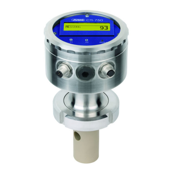
10 Operation 10.1 Operating elements JUMO CTI-750 with and with- LC-Display (1) Graphical LC-display, (6) LEDs «K1» / «K2» indicate the background lit up. status of the switching outputs. In normal operation, the LED (2) Key flows when the corresponding confirm inputs, select menu.
-
Page 37
10 Operation LC-Display (11) (10) Output K1 is active Output mode — manual (manual operation) Output K2 is active — hold (hold operation) Binary input 1 is Conductivity /concentration- triggered measured value Binary input 2 is Unit of the conductivity- /con- triggered centrations measured value Keyboard is locked… -
Page 38: Principle Of Operation
10 Operation 10.2 Operation principle 10.2.1 Operating in levels Measurement mode, see chapter 10.4 «Measurement mode», page 41 OPERATOR LEVEL, see chapter 10.5 «Operating level», page 41 INPUT CONDUCTIVITY MEASUREMENT RANGE 1…4 TEMP.COMPENSATION TEMP.COEFFICIENT 1…4 REFERENCE TEMPERATURE REL.CELL CONSTANT MOUNTING FACTOR CONCENTR.MEASUREMENT CONCENTR.RANGE OFFSET…
-
Page 39
10 Operation DEVICE DATA LANGUAGE CONTRAST LIGHTING LCD INVERSE ADMINISTR.-LEVEL, see chapter 10.6 «Administrator level», page 49 Password PARAMETER-LEVEL, see chapter 10.6.1 «Parameter level», page 50 INPUT CONDUCTIVITY. OUTPUT CONDUCTIVITY INPUT TEMPERATURE OUTPUT TEMPERATURE OUTPUT BINARY 1 OUTPUT BINARY 2 INPUT BINARY 1 INPUT BINARY 2 DESALINATION FUNCTION… -
Page 40: Principle
10 Operation 10.3 Principle Level…
-
Page 41: Measurement Mode
10 Operation 10.4 Measurement mode Depiction In the measurement mode, the conductivity compensated to the reference temperature, or the concentration, and the temperature of the measurement medium are displayed. MEASUREMENT -> Measurement mode 20.5°C -> Temperature of the measurement medium 203 mS/cm ->…
-
Page 42: Input Conductivity
10 Operation 10.5.1 INPUT CONDUCTIVITY (Input conductivity) MEASUREMENT RANGE 1…4 0…500 µS/cm 0…1000 µS/cm 0…2000 µS/cm 0…5000 µS/cm 0…10 mS/cm 0…20 mS/cm 0…50 mS/cm 0…100 mS/cm 0…200 mS/cm 0…500 mS/cm 0…1000 mS/cm 0…2000 mS/cm UNK The measurement ranges 2, 3 and 4 are only used if «INPUT BINARY»…
-
Page 43: Mounting Factor
10 Operation MOUNTING FACTOR 80.0…100.0…120% If the minimum distances (20 mm) of the sensor to the outer wall cannot be maintained, a limited compensation can be achieved with this parameter. CONCENTR. MEASUREMENT NO FUNCT. NaOH HNO3 CUST. SPEC. (The input of the values is only possible with the optional Setup program) CONCENTR.
-
Page 44: Output Conductivity
10 Operation 10.5.2 OUTPUT CONDUCTIVITY. (Output conductivity) SIGNAL TYPE 0…20 mA 4…20 mA 20…0 mA 20…4 mA 0…10 V 2…10 V 10…0 V 10…2 V SCALING START 1…4 0 µS/cm = 4 mA Can be set in the current measurement range, depending on the signal type The ranges 2, 3 and 4 are only used if «INPUT BINARY»…
-
Page 45: Unit
10 Operation 10.5.3 INFLOW TEMPERATURE UNIT °C °F MEASUREMENT VALUE ACQUISITION Sensor manual MANUAL SPECIFICATION -20.0…25.0…150.0°C OFFSET -15.0…0.0…+15.0°C FILTERING TIME 00:00:00…00:00:01…00:00:25 H:M:S 10.5.4 OUTFLOW TEMPERATURE SIGNAL TYPE 0…20 mA 4…20 mA 20…0 mA 20…4 mA 0…10 V 2…10 V 10…0 V 10…2 V SCALING START -20 …
-
Page 46: Output Binary
10 Operation AT THE TIME OF CALIBRATION ACCOMPANYING FROZEN SAFETY VALUE SAFETY VALUE 0,0…4,0…22,0 mA (depending on the signal type) 0…10,7 V MANUAL OPERATION MANUAL VALUE 0,0…4,0…22,0 mA (depending on the signal type) 0…10,7 V 10.5.5 OUTPUT BINARY 1 and OUTPUT BINARY 2 FUNCTION NO FUNCTION COND.
-
Page 47: Distance
10 Operation Hysterese Hysteresis Cond. Distance Abstand Limit value Grenzwert Setpoint Sollwert Alarm window LK1 Alarm window LK2 Wiper contact Wiper contact Triggering condition longer than Triggering condition shorter than pulse duration pulse duration LIMIT VALUE -20.0… 999.0 (depending on the function, see above) HYSTERESIS 0.0…1.0…999.0 (depending on the function, see above) DISTANCE…
-
Page 48: Desalination Function
10 Operation SWITCH-ON DELAY 00:00:00…01:00:00 H:M:S SWITCH-OFF DELAY 00:00:00…01:00:00 H:M:S PULSE DURATION 00:00:00…01:00:00 H:M:S (see above: «Function, wiping contact) 10.5.6 INPUT BINARY 1 and INPUT BINARY 2 FUNCTION NO FUNCTION KEYBOARD LOCK/HOLD MEASUREMENT RANGE./TEMP C. DESALINATION FUNCTION. Setting parameters binary input 1 binary input 2 Measurement range- / MB1 / Tk1…
-
Page 49: Administrator Level
10 Operation 10.5.8 DEVICE DATA LANGUAGE GERMAN ENGLISH FRENCH SPANISH POLISH SWEDISH ITALIAN PORTUGUESE DUTCH RUSSIAN By inputting the password 7485 in the Administrator level, the operating language is reset to English. CONTRAST 0…6…11 LIGHTING FOR OPERATION (about 50 s after the last keystroke, the lighting gets switched off) INVERSE LCD 10.6 Administrator level…
-
Page 50: Levels Of The Administrator Level
10 Operation Levels of the Administrator level 10.6.1 Parameter level In this level, the Administrator can edit any parameter of the operator level. The structure of the parameter level in the Administrator level is identical to the operator level see «Operating level», page 41 and onwards. 10.6.2 Release level In this level, the Administrator can determine which parameters the operator is permitted to modify in the operator level..
-
Page 51: Calibration Level
10.7.1 REL. CELL CONSTANT. (relative cell constant) If this function has been released by the Administrator, the operator can cali- brate the relative cell constant of the JUMO CTI-750 here; see «Calibration of the relative cell constant», page 56. 10.7.2 TEMP. COEF. LINEAR (Temperature coefficient linear) If this function has been released by the Administrator, the operator can cali- brate the JUMO CTI-750 on fluids with linear temperature coefficients;…
-
Page 52: The Desalination Function
— The desalination function is only possible in the mode «Conductivity mea- the case of the surement». Not in the case of concentration measurement.. JUMO CTI-750 — If the desalination function is activated, all the parameters that are not rele- vant for this function are turned off.
-
Page 53: Desalination Reduction
10 Operation — The desalination reduction can be set in the range from 1…50% below the actual limit value of binary input 1. The default setting is 10% below the limit value. 10.8.1 Setting the desalination function All the parameters are plant-dependent and must be matched to the prevalent conditions.
-
Page 54
10 Operation With the keys , select «DESALINATION FUNCT.». with key confirm the selection. Use the key to switch to the operator level. EXIT With the key select «DESALINATION FUNCTION». With key , confirm the selection. Set the desalination reduction with the keys in the range from 1…10…50% below the actual limit value. -
Page 55
10 Operation With the keys , select «LOCKING TIME»; with key , confirm the selection. Set the locking time with the keys in the range from 0:00:00…00:01:00…18:00:00 H:M:S. with key , confirm the setting. If there is a failure of the supply voltage during the running of the desalination function, the function is canceled. -
Page 56: Calibrating
In case of increased demands on the accuracy, the cell constant must first be calibrated. Precondition — the JUMO CTI-750 must be supplied with power. see chapter 7 «Installation», page 30ff. — The sensor must be connected to the transmitter (in case of «shouldered»…
-
Page 57: Calibration Of The Temperature Coefficient Of The Measurement Solution
Press the key. The relative cell constant calculated by the JUMO CTI-750 is displayed. Accept the relative cell constant determined -> press the key for longer than 3 seconds, or discard the value ->…
-
Page 58
11 Calibration Precondition — the JUMO CTI-750 must be supplied with power. see chapter 7 «Installation», page 30ff. — The sensor must be connected to the transmitter (in case of «shouldered» construction). — The transmitter is in «Measurement mode». Submerge the conductivity sensor in a sample of the measurement solu- tion. -
Page 59
During the calibration, the temperature changing speed of the measurement solution of 10 K/min in the case of JUMO CTI-750 with a free-standing tem- perature sensor or 1 K/min in the case of JUMO CTI-750 with an integrated tempera- ture sensor must not be exceeded. -
Page 60: Determining The Tc-Curve
11.3.2 Non-linear temperature coefficient (ALPHA) General Since the temperature coefficient of some media is not constant over a larger temperature range, the JUMO CTI-750 has the facility to divide a temperature range (T to T ) into 5 sub-ranges. In each of these ranges, compensation start can be carried out with different TC values.
-
Page 61
Here, the temperature range from the starting to the final temperature calibration on is divided into 5 equal sections. the JUMO CTI- The temperature range must be greater than 20 Kelvin and overlap the refer- ence temperature. Example: Reference temperature 25°C, starting temperature 18°C and final… -
Page 62
— 10 K/min in case of a free-standing temperature sensor and — 01 K/min in case of an integrated temperature sensor Precondition — the JUMO CTI-750 must be supplied with power. see chapter 7 «Installation», page 30ff. — The sensor must be connected to the transmitter (in case of «shouldered»… -
Page 63
11 Calibration With the keys , input the starting temperature and confirm with key . The starting temperature must be below the reference temperature (25.0°C). With the keys , input the final temperature and confirm with the key . The final temperature must be at least 20°C above the starting temperature. -
Page 64
The next temperature to be reached is displayed flashing. During the calibration, the temperature changing speed of the measurement solution of 10 K/min in the case of JUMO CTI-750 with a free-standing tem- perature sensor or 1 K/min in the case of JUMO CTI-750 with an integrated tempera- ture sensor must not be exceeded. -
Page 65: Maintenance
12 Maintenance 12.1 Conductivity-clean sensor Do not use any solvents. Stubborn sediments or deposits can be dissolved with dilute hydrochloric acid and removed. Comply with the safety specifications. Deposits Deposits on the sensor part can be removed with a soft brush (e.g. bottle brush).
-
Page 66: Rectifying Errors And Faults
13 Rectifying errors and faults Error Problem Possible cause Measure possibilities No display of measured Voltage supply absent Check voltage supply, value check terminals signal output Measured value display Sensor not submerged in Fill up tank 000 or medium; signal output 0% Tank level too low (e.g.
-
Page 67
In case of display values up to 20 mS, the resistance loop must have 1 turn. In case of display values from 50 mS onwards, the resistance loop must have 3 turns. The cell constant of the JUMO CTI-750 depends on the structural shape.! The Tee measuring cell has a cell constant of 6.80 1/cm. -
Page 68
13 Rectifying errors and faults Example 1 The JUMO CTI-750 with Tee-shaped measuring cell should display 20 mS: ·6.80 1/cm Ω = 340 20·10 S/cm To get a display of 20 mS/cm, the resistance loop (with 1 turn) must have a re- sistance of 340 Ohm. -
Page 69: Pre-Calculated Values
13 Rectifying errors and faults Pre-calculated The display value 0 is obtained when the sensor is dry and without conducting values coats, as well as when there is no resistance loop. Structural shape/ Cell constant Material: PVDF Material: PEEK Material: PEEK K = 6.80 1/cm K = 5.45 1/cm K = 6.50 1/cm…
-
Page 70
13 Rectifying errors and faults Carry out test Determine test resistance. Connect the JUMO CTI-750 electrically, see chapter 7 «Installation», page Select the corresponding measurement range, see chapter 10.5.1 «INPUT CONDUCTIVITY (Input conductivity)», page 42 -> MEASUREMENT RANGE 1…4 Set TC to 0%/K, see chapter 10.5.1 «INPUT CONDUCTIVITY (Input con- ductivity)», page 42 ->… -
Page 71
Carry out test Prepare the conductivity test solution in a sufficiently large container Connect the JUMO CTI-750 electrically, see chapter 7 «Installation», page Select the measurement range according to the conductivity test solution, see chapter 10.5.1 «INPUT CONDUCTIVITY (Input conductivity)», page 42 — >… -
Page 72: Annex
14 Annex 14.1 Before configuring If many parameters of the device are to be re-configured, it is advisable to make a note of all the parameters to be changed in the following table, and to process the parameters in the given sequence. The following list shows the maximum number of modifiable parameters.
-
Page 73: Unit
14 Annex Parameter Selection / Range of values New setting see page Factory setting Signal type 0…20 mA 4…20 mA 20…0 mA 20…4 mA 0…10 V 2…10 V 10…0 V 10…2 V Scaling, beginning 0…90% = 4 mA (e.g.) from the measurement range scope Scaling: End 100…10% = 20 mA (e.g.) from measurement range scope…
-
Page 74: Distance
14 Annex Parameter Selection / Range of values New setting see page Factory setting Scaling: End -3…150…200°C = 20 mA (100…10% of measurement range scope) In case of an alarm high safety value At the time of calibration accompanying frozen safety value Safety value 0.0…4.0…22.0 mA…
-
Page 75: Lighting
14 Annex Parameter Selection / Range of values New setting see page Factory setting Function no function Keyboard locking/ Hold Measurement range / Temperature coefficient desalination function Desalination function Reduction 0…10…50% Dosing time 00:00:00…00:01:00…18:00:00 H:M:S Locking time 00:00:00…00:01:00…18:00:00 H:M:S Device data Language German English…
-
Page 76
JUMO GmbH & Co. KG JUMO Instrument Co. Ltd. JUMO Process Control, Inc. Street address: JUMO House 8 Technology Boulevard Moltkestraße 13 — 31 Temple Bank, Riverway Canastota, NY 13032, USA 36039 Fulda, Germany Harlow, Essex CM20 2TT, UK Phone:…
|
Detail Specifications: 703/703765-cti750.pdf file (08 Oct 2022) |
Accompanying Data:
JUMO CTI-750 Transmitter PDF Operating Instructions Manual (Updated: Saturday 8th of October 2022 04:23:13 PM)
Rating: 4.8 (rated by 97 users)
Compatible devices: dTRANS p02 DELTA, Wtrans p, dTRANS T02j, 4AP-30, dTRANS T02 Ex, DELOS SI, CTI-500, dTRANS T02 LCD.
Recommended Documentation:
Text Version of Operating Instructions Manual
(Ocr-Read Summary of Contents, UPD: 08 October 2022)
-
23, 23 7 Installation ❏ The choice of cable, the installation and the electrical connection must conform to the requirements of VDE 0100 “Regulations on the Installation of Power Circuits with Nominal Voltages below 1000 V” or the appropriate local regulations. ❏ The electrical connection must only be carried out by qualified personnel. ❏ If contact with live parts …
-
61, 61 13 Eliminating faults and malfunctions Test sequence ✱ Calculate the test resistance. ✱ Connect up the JUMO CTI-750, see Chapter 7 “Installation”, page 23. ✱ Select the corresponding measurement range, see Chapter 10.4.1 “CONDUCTIVITY IN (conductivity input)”, page 33 -> RANGE 1 — 4 ✱ Set TC to 0%/°C, see Chapter 10.4.1 “CONDUCTIVITY IN (conductivity …
-
25, 25 7 Installation Wiring Caution: On devices with a separate sensor and M12 plug/socket connectors, the screw terminals are sealed inside the device. Removal of this sealing will invalidate the warranty! For devices with a separate sensor (type code extensions (2) /60 or /65), the transmitter and detached sensor are matched to one another at the factory! When connect…
-
19, JUMO CTI-750 19 6 Mounting 6.3 JUMO CTI-750 with separate sensor (split version) Transmitter head Drilling jig for wall-mounting
… -
58, 13 Eliminating faults and malfunctions 58 13.1.1 Resistance loop test Position of the resistance loop ✱ Loop a wire through the cell (see diagram) ✱ Connect a resistor R to the wire Calculating the resistance Formula for calculating the resistance of the resistance loop: Note: 1 mS/cm = 1·10 -3 S/cm 1 µS/cm = 1·10 -6 S/cm For display values up to 20 mS…
-
3, Contents 1 Typographical conventions ……………………………………………… 5 1.1 Warning signs ………………………………………………………………………………….5 1.2 Note signs ……………………………………………………………………………………….5 2 General ………………………………………….…
-
36, 10 Operation 36 10.4.3 TEMPERATURE IN DIMENS. UNIT °C °F MEAS. MODE SENSOR MANUAL MANUAL VALUE 0.0 to 25.0 to 150°C OFFSET -15.0 to 0.0 to 15.0°C FILTER TIME 00:00:00 — 00:00:01 — 00:00:25 H:M:S 10.4.4 TEMPERATURE OUT SIGNAL TYPE 0 — 20 mA 4 — 20 mA 20 — 0 mA 20 — 4 mA 0 — 10 V 2 — 10 V 10 — 0 V 10 — 2 V SCALING START 0.0°C = 4 mA (depending on th…
-
26, 7 Installation 26 Connections for the transmitter Connection Screw terminals Conn./pin Supply standard: supply voltage 19 — 31 V DC (with reverse-polarity protection) with extra code 844: 24 V AC 1 L+ 2 L- I / 1 I / 2 Outputs Analog signal output: Conductivity/concentration 0 — 20 mA resp. 20 — 0 mA or 4 — 20 mA resp. 20 — 4 mA or 0 — 10 V res…
-
12, JUMO CTI-750 4 Instrument identification 12 4.4 JUMO CTI-750 as “Transmitter with separate sensor” x= standard o = option 1 The PC setup program is required for programming the instrument, see accessories. 2 fixing items (union/ring nuts, mounting brackets) are not included in delivery. If required, please include in order, see accessories. 3 If required, order M12 plug/socket connect…
-
4, Contents 10 Operation ……………………………………………………………………… 29 10.1 Controls …………………………………………………………………………………………29 10.2 Principle of operation ………………………………………………………………………31 10.3 Measurement mode ………….…
-
56, JUMO CTI-750 56 12 Maintenance 12.1 Cleaning the conductivity sensor Deposits Deposits on the sensor section can be removed with a soft brush (e.g. a bottle brush). Do not use solvents. Hard-to-remove crusts and deposits can be softened and removed with dilute hydrochloric acid. Observe the safety regulations!
…
Recommended Instructions:
KS-F350R, PM6003, SV-DVD440, DRC-605, 216


-
KERN & Sohn GmbH Ziegelei 1 D-72336 Balingen E-Mail: [email protected] Phone: +49-[0]7433- 9933-0 Fax: +49-[0]7433-9933-149 Internet: www.kern-sohn.com Operating and Installation Instructions Digital weighing transmitter KERN YKV-01/02 Version 1.1 2019-04 GB YKV-01-02-BA_IA-e-1911 …
YKV-01 27
-
SynthesizedBase StationTransmitterBST-75 OPERATOR’S MANUAL (72-76 MHz)357 West 2700 South • Salt Lake City, Utah 84115 • Phone: (800) 496-3463 • Fax: (801) 484-6906 • www.comtek.com …
BST-75 16
-
DL-HDE100 Installation GuideIncluded Accessories:IR Receiver (IR eye) — 2 eaIR Transmitter (IR emitter) — 2 eaPower Supply with locking connectorUS Power Cable3-pole Terminal Block — 2 ea (attached to the extenders)Mounting brackets with screws — 4 ea …
DL-HDE100 4
Additional Information:
Popular Right Now:
Operating Impressions, Questions and Answers:
Table of Contents for JUMO CTI-750:
-
11 Calibration 70 TC curve Temperature compensation with the TC curve The present temperature of the medium is applied to the TC curve to deter- mine the corresponding temperature coefficient, see “TC curve”, page 70. Intermediate values, e.g. (α x at T x ) between two known values (α 3 at T 3 ) and (α 4 at T 4 ) are derived through a linear interpolation. The derived TC is used to calculate the compensated conductivity, in the same way as with the linear compensation. NOTE! If the
-
73 11 Calibration ✱ Warm up the sample medium until is it above/below the temperature that is blinking. The next target measured temperature is displayed as blinking. ✱ Warm up the sample medium until is it above the temperature that is blinking. ✱ Repeat the procedure as often as required, until the device has determined all 6 temperature coefficients. The LC display now shows the derived temperature coefficients in %/°C. ✱ To accept the temperature coefficients that have been determined -> press the key for at least 3
-
4 Instrument identification 12 4.4 The device as «Transmitter with separate sensor» (1) (2) (3) (4) (5) (6) Order code / — — — / , … a Order example 202756 / 10 — 607 — 0000 — 82 / 767 a List extra codes in sequence, separated by commas. (1) Basic type 202756 Inductive transmitter/switching device for conductivity/ concentration and temperature (2) Basic type extension 20 Transmitter in plastic housing, without display/keypad (without sensor) a, b 25 Trans
-
9 3 Inductive conductivity measurement 3.2 Function of the transmitter The instrument has been designed for use on site. A rugged housing protects the electronics and the electrical connections from corrosive environmental conditions (enclosure IP67). As standard, the device has one analog signal output each for conductivity/concentration and temperature respectively. Further processing of the standard signals can take place in a suitable display/ control device, or, for example, directly in a PLC. The output signals are electrically i
-
10 Operation 50 10.5.1 CONDUCTIVITY IN (conductivity input) RANGE 1 — 4 1 0 — 500 µS/cm 0 — 1000 µS/cm 0 — 2000 µS/cm 0 — 5000 µS/cm 0 — 10 mS/cm 0 — 20 mS/cm 0 — 50 mS/cm 0 — 100 mS/cm 0 — 200 mS/cm 0 — 500 mS/cm 0 — 1000 mS/cm 0 — 2000 mS/cm UNC 2 1 Measurement ranges 2, 3 and 4 are only used if BINARY INPUT is configured to RANGE/TEMPCO. 2 This measurement range is not temperature-compensa
-
23 6 Installation Version with process connection 690 = SMS 2″ and extra code 767 and 941 Version with process connection 690 = SMS 2″ and extra code 768 Version with process connection 955 = Pressing screw G 1″ EL = 57 mm Version with process connection 956 = Pressing screw G1″ EL = 87 mm < 200Nm 1 2 1 < 200Nm 1 3 1 36 2 1 (<20Nm) 36 2 1 1 (<20Nm) 1 = stainless steel 1.4301 2 = PEEK 3 = PVDF < 20Nm) ( < 20Nm) (
-
6 Installation 32 Clamp (1) Process connection 617, Clamp 2 1/2″, PEEK (2) Clamping ring, 1.4301, (3) Tee, short, 2.5″ — 2″ similar to DIN 11852, and 2″ clamp adapter, 1.430 (to be provided by the plant operator; not supplied by the device manufacturer) Varivent ® (1) Tee, VARIVENT ® , DN 50, 1.4404 (to be provided by the plant operator; not supplied by the device manufacturer) (1) (2) (3) (1)
-
77 13 Eliminating faults and malfunctions ✱ Connect resistor R to wire Calculating resistance Formula for calculating the resistance of the resistor loop: Note: 1 mS/cm = 1·10-3 S/cm 1 µS/cm = 1·10-6 S/cm For display values up to 20 mS, the resistor loop must have one winding. For display values up to 50 mS, the resistor loop must have three windings. Example 1 The device with a T-shaped PVDF measuring cell should
-
61 10 Operation 10.8.1 Stop dilution All the parameters are system-dependent, and must be adjusted to suit sys- tem requirements. ✱ Press the key for at least 3 seconds. ✱ Use the or key to select OPERATOR LEVEL; use the key to confirm the selection. ✱ Use the or key to select BINARY INPUT; use the key to confirm the selection. ✱ Use the or key to select DILUTION; use the key to confirm the selection. PGM PGM PGM PGM
-
29 6 Installation Varivent ® Split version with process connection 955 = Pressing screw G 1″ EL = 57 mm and extra code 767 Split version with process connection 956 = Pressing screw G1″ EL = 87 mm and extra code 767 Split version with process connection 686 = VARIVENT ® DN 40/50 and extra code 767 and 941 (retaining clip not included in delivery) 36 1 2 1 3 6
-
37 7 Installation Wiring 7.2 Electrical connection 7.2.1 Transmitter with electrical connection 82 (cable glands) Head transmitter ATTENTION! To connect the single conductors, pull off the pluggable screw terminals (1) in the operating unit. Pass the connecting cables through the cable glands (2). DANGER! For devices with a separate sensor, the transmitter and detached sensor are matched to one another at the factory! When connecting the components, please note that the serial number of the external sensor (marked on the label attached to th
-
13 Eliminating faults and malfunctions 78 Pre-calculated values Display value 0 is obtained if the following conditions are met: • the sensor is dry and • the sensor does not have any conductive coatings and • a resistor loop is not installed. Running the test ✱ Define the test resistance. ✱ Electrically connect the device, see Chapter 7 “Installation”, page 35. ✱ Install resistor loop as shown in the diagram. D
-
69 11 Calibration 11.3.2 Non-linear temperature coefficient (ALPHA) General Since the temperature coefficient of some media is not constant over a sizeable temperature range, the device provides the option of subdividing a temperature range (T Start to T End ) into 5 sections. A different TC value can be used for compensation in each of these range sections. This «TC curve» can be • edited with the setup program and trans
-
10 Operation 46 10.2 Principle of operation 10.2.1 Operation in levels Measurement mode, see Chapter 10.4 «Principle of operation» page 39 OPERATOR LEVEL, see chapter 10.5 «Operator level», page 39. INPUT CONDUCTIVITY MEASUREMENT RANGE 1…4 TEMPERATURE COMPENSATION TEMP. COEFFICIENT 1…4 REFERENCE TEMPERATURE REL. CELL CONSTANT MOUNTING FACTOR CONCENTR. MEASUREMENT CONCENTR. RANGE OFFSET FILTER TIME CALIBR. IN
-
45 10 Operation LC display (1) Output K1 is activ (2) Output K2 is activ (3) Binary input 1 is activated (4) Binary input 2 is activated (5) Keypad is inhibited (6) Device status (indications) • Alarm (e.g. overrange) • Calib blinking (calibration timer has run down) •Calib (customer calibration is active) (7) Output mode • Hand (manual operation) • Hold (hold operation) (8) Conductivity/concentration measurement (9) Unit for conductivity/concentration measurement (10) Temperature of the medium (11) Device status e.g. •Measurement (normal) • Diluti
Questions, Opinions and Exploitation Impressions:
You can ask a question, express your opinion or share our experience of JUMO CTI-750 device using right now.
Download Operating instructions manual of JUMO CTI-750 Transmitter for Free or View it Online on All-Guides.com.

1

2

3

4

5

6

7

8

9

10

11

12

13

14

15

16

17

18

19

20

21

22

23

24

25

26

27

28

29

30

31

32

33

34

35

36

37

38

39

40

41

42

43

44

45

46

47

48

49

50

51

52

53

54

55

56

57

58

59

60

61

62

63

64

65

66

67

68

Inductive
Conductivity Transmitter
JUMO CTI-750
Type 202756
B 20.2756.0
Operating Instructions
12.05/00452846