1)cant turn it into manual or semi auto..totally no function at all,
2)cant call out this 2 page…(photo attached )
3)that an error 21.0 from the servo motor controller…
some craazy guy try to repair the machine half way,had mess up all the wiring,and dismentle the servo motor n leave it on the floor…
(*Encoder communication error protection / Error code no 21 /Communication between the encoder and the driverhas been interrupted in certain times, and disconnection detecting function has been triggered.)
4) something wrong with Hoerbiger PVR6 wiring,
a) that no connection wire 244 for enable, x14/1 & x14/2
b) i dnt have the hyraulic circuit drawing,but as i understand,it should have a proportional relief valve to control pressure…Y6 — x5/1 & x5/2 or Y5 — x5/3 & x5/4
5) since someone add a external LCD,i also suspect inside all the cybelec component may be mess up too, ,i need to double check all pcb connection as well.
.thumb.jpeg.ba903284809a4164cdbbd31854d8f299.jpeg)
.thumb.jpg.3a7e9398db9a941ce7aa8e3c958ce15e.jpg)
![]()
ModEva/DNC880S
PC 1200 2D
2D Reference Manual
|
CYBELEC SA |
Tel. ++ 41 24 447 02 00 |
|
RUE DES UTTINS 27 |
Fax ++ 41 24 447 02 01 |
|
CH — 1400 YVERDON-LES-BAINS |
E-Mail: info@cybelec.ch |
|
SWITZERLAND |
V-DOC-MODEVA-EN |
|
TABLE OF CONTENTS |
|
|
INTRODUCTION……………………………………………………………………………………………………………… |
5 |
|
About this Manual |
5 |
|
Licence Agreement and Copyright |
5 |
|
CONVENTIONS………………………………………………………………………………………………………………. |
7 |
|
DEFINITIONS………………………………………………………………………………………………………………….. |
11 |
|
ABS ……………………………………………………………………………………………………………………. |
11 |
|
REL |
11 |
|
Active Peripherals ………………………………………………………………………………………………… |
12 |
|
Active Peripherals Machine |
12 |
|
Active Peripheral Products |
13 |
|
Active Peripheral Punches / Dies |
13 |
|
Admissible Force applied to the Dies………………………………………………………………………. |
13 |
|
Alphanumeric Fields……………………………………………………………………………………………… |
15 |
|
Angle Corrections…………………………………………………………………………………………………. |
16 |
|
General Remarks |
16 |
|
Direct Corrections |
16 |
|
Angular Corrections |
17 |
|
Corrections by Thickness Measurement |
17 |
|
Measuring at the TDC |
18 |
|
Measuring at the PP |
20 |
|
Independent Thickness Correction Y1-Y2 |
22 |
|
Corrections: Sensitivity BDC |
22 |
|
Auxiliary Functions ……………………………………………………………………………………………….. |
23 |
|
Backgauge Retraction …………………………………………………………………………………………… |
23 |
|
Bend …………………………………………………………………………………………………………………… |
23 |
|
At the bottom of the Die |
23 |
|
Final |
23 |
|
Intermediate |
23 |
|
Sequence without Bend |
24 |
|
Bend Counter ………………………………………………………………………………………………………. |
24 |
|
Bending Force ……………………………………………………………………………………………………… |
24 |
|
Bending Order ……………………………………………………………………………………………………… |
25 |
|
Automatic Bending Order |
25 |
|
Modifying the Bending Order |
25 |
|
Unbend Mode |
27 |
|
Bending Speed…………………………………………………………………………………………………….. |
29 |
|
BG (Backgauge) or STOP……………………………………………………………………………………… |
29 |
|
Bottoming ……………………………………………………………………………………………………………. |
30 |
|
Corrections (Table)……………………………………………………………………………………………….. |
31 |
|
Crowning …………………………………………………………………………………………………………….. |
32 |
|
MODEVAREF2D_EN.DOC |
TABLE OF CONTENTS |
PAGE 1 |
|
Data Backup ……………………………………………………………………………………………………….. |
32 |
|
|
Data Transfer………………………………………………………………………………………………………. |
33 |
|
|
Date and Hour …………………………………………………………………………………………………….. |
35 |
|
|
Decentered Punches & Backgauge Correction………………………………………………………… |
36 |
|
|
Depth Collision authorized…………………………………………………………………………………….. |
36 |
|
|
Drawing………………………………………………………………………………………………………………. |
37 |
|
|
Dwell Time ………………………………………………………………………………………………………….. |
38 |
|
|
Erase / Delete ……………………………………………………………………………………………………… |
38 |
|
|
Erasing Memories………………………………………………………………………………………………… |
39 |
|
|
Free Memory ………………………………………………………………………………………………………. |
39 |
|
|
Gauge Clearance ………………………………………………………………………………………………… |
40 |
|
|
Ideal Curve (CR)………………………………………………………………………………………………….. |
41 |
|
|
PRODUCT NUM Page |
41 |
|
|
Indexing Axes ……………………………………………………………………………………………………… |
46 |
|
|
Inserting a Sequence……………………………………………………………………………………………. |
46 |
|
|
Internal Radius…………………………………………………………………………………………………….. |
47 |
|
|
Keyboard ……………………………………………………………………………………………………………. |
48 |
|
|
L. Bending…………………………………………………………………………………………………………… |
48 |
|
|
Language……………………………………………………………………………………………………………. |
49 |
|
|
Leaving the Software……………………………………………………………………………………………. |
49 |
|
|
Leg…………………………………………………………………………………………………………………….. |
50 |
|
|
Length………………………………………………………………………………………………………………… |
51 |
|
|
Low Speed Distance ………………………………………………………………………………………… |
51 |
|
|
Machine Parameters ……………………………………………………………………………………………. |
51 |
|
|
Maintenance ……………………………………………………………………………………………………….. |
52 |
|
|
Manual Adjustment of the Backgauge…………………………………………………………………….. |
52 |
|
|
Modifying the Origin of the Axes…………………………………………………………………………….. |
53 |
|
|
Parametric product ………………………………………………………………………………………………. |
55 |
|
|
Activation of the function |
55 |
|
|
Create a parametric product |
55 |
|
|
Working with a parametric product |
59 |
|
|
Product Groups……………………………………………………………………………………………………. |
60 |
|
|
Definitions |
60 |
|
|
Working example in the PRODUCTS GROUP page |
61 |
|
|
Product information ……………………………………………………………………………………………… |
62 |
|
|
See an Informtion |
63 |
|
|
Creating an Information (text only) |
63 |
|
|
Creating an Information (text and images) |
63 |
|
|
Product Management …………………………………………………………………………………………… |
66 |
|
|
Programming a Profile………………………………………………………………………………………….. |
67 |
|
|
Programming on Bend Num………………………………………………………………………………….. |
67 |
|
|
Programming while working ………………………………………………………………………………….. |
68 |
|
|
Q.Needed. ___ Done.___……………………………………………………………………………………… |
69 |
|
|
Reference YR cor. ……………………………………………………………………………………………….. |
69 |
|
|
Screen Capture……………………………………………………………………………………………………. |
70 |
|
|
Black and white, colour |
70 |
|
|
Screen printing |
71 |
|
|
Searching for Products according to Criteria …………………………………………………………… |
73 |
|
|
Memorization date |
74 |
|
|
Section……………………………………………………………………………………………………………….. |
75 |
|
|
Sigma…………………………………………………………………………………………………………………. |
75 |
|
|
Simulation criteria ………………………………………………………………………………………………… |
76 |
|
|
SP (Switch Point)…………………………………………………………………………………………………. |
79 |
|
|
Special bends ……………………………………………………………………………………………………… |
80 |
|
|
Preliminary / Final bend |
80 |
|
|
Start Axes/AF………………………………………………………………………………………………………. |
85 |
|
|
PAGE 2 |
2D REFERENCE MANUAL MODEVA/DNC 880S |
|
TDC (Top Dead Centre)………………………………………………………………………………………… |
86 |
|
Tolerance…………………………………………………………………………………………………………….. |
87 |
|
Too short segment authorized ……………………………………………………………………………….. |
88 |
|
Tools…………………………………………………………………………………………………………………… |
88 |
|
Programming punches |
89 |
|
Programming dies |
91 |
|
Modifying a tool |
93 |
|
Tool positions |
93 |
|
Punch list / Die list |
93 |
|
Unfolded Length …………………………………………………………………………………………………… |
94 |
|
DIN |
95 |
|
REAL |
95 |
|
Correction coefficient of calculation DIN 6935 |
95 |
|
INDEX ……………………………………………………………………………………………………………………………. |
97 |
This page has been left blank intentionally.
PAGE 4 2D REFERENCE MANUAL MODEVA/DNC 880S

INTRODUCTION
ABOUT THIS MANUAL
This document has been conceived to try and answer particular questions after having acquired the basis for using the ModEva/DNC 880S software. It is complementary to the User guide which informs you about the basic procedures to be followed for using this software.
A supplement called 3D Reference manual is supplied with the ModEva software in 3D version.
This manual is organized like a dictionary, that its elements are classed in alphabetical order.
If a subject is dealt with in another chapter than the one in which you are looking for information, you will find a reference to the new subject. An index situated at the end of the manual completes and facilitates the search for information. Do not hesitate to use it.
Some functionalities treated in this manual are not available on
DNC 880S.
LICENCE AGREEMENT AND COPYRIGHT
This manual is subject to the licence and copyright agreement to be found at the beginning of this manual.
This page has been left blank intentionally.
PAGE 6 2D REFERENCE MANUAL MODEVA/DNC 880S
![]()
CONVENTIONS
As a general rule, in this manual, we will not repeat how to validate a field, select a tool, call a page or any other basic manipulations.
These are described by means of examples in the User guide of the numerical control or the relevant software.
In order to ensure a better readability of the reproduced screens, these ones have been converted in black and white.
Possibly, certain screens illustrated in this manual may not correspond exactly to your software, this can result from the configuration of your software (number of options, axes, etc.) or from the used software version (DOS or Windows).
Typographical conventions
|
Arial bold |
Quotations of text as seen on the screen. |
|||||||||||
|
Arial bold italic |
Used to indicate the name of a DNC input or |
|||||||||||
|
output. |
||||||||||||
|
Italic |
Reference to a written element , a paragraph or |
|||||||||||
|
a manual. |
||||||||||||
|
For example: See Typographical conventions. |
||||||||||||
|
Indicates a double pressure on the |
key. |
|||||||||||
General conventions for this manual
|
It is accepted that: |
||||||||
|
Mouse |
means a mouse for a PC |
|||||||
|
or trackball / tracksensor for a DNC. |
||||||||
|
Click |
press the left mouse button. |
|||||||
|
Click right |
press the right mouse button. |
|||||||
|
Click left/right |
press |
simultaneously the left and right mouse |
||||||
|
buttons. |
||||||||
|
Round robin lists |
or multiple choice fields: |
|||||||
|
They are violet coloured and signify that several |
||||||||
|
options are available. |
||||||||
|
The choice of the contents is made by pressing |
||||||||
|
the |
key. |
|||||||
|
A window appears displaying the list of the |
available choices for this field. To validate the choice:
— type the number indicated next to the choice, or
— place the cursor on the choice and press the 

 key.
key.

It is possible, without displaying the choice window, to make appear one after the other the
choices by pressing the 

 key. To validate, leave the field.
|
Function keys |
Each time you are asked to press a function |
||||||||||||||||||||||||||||||||||
|
key |
to |
, the appropriated menu |
|||||||||||||||||||||||||||||||||
|
appears. |
|||||||||||||||||||||||||||||||||||
|
Generally, the name of the function key will be |
|||||||||||||||||||||||||||||||||||
|
used. For example: press PRODUCT |
|||||||||||||||||||||||||||||||||||
|
designates the |
key. |
||||||||||||||||||||||||||||||||||
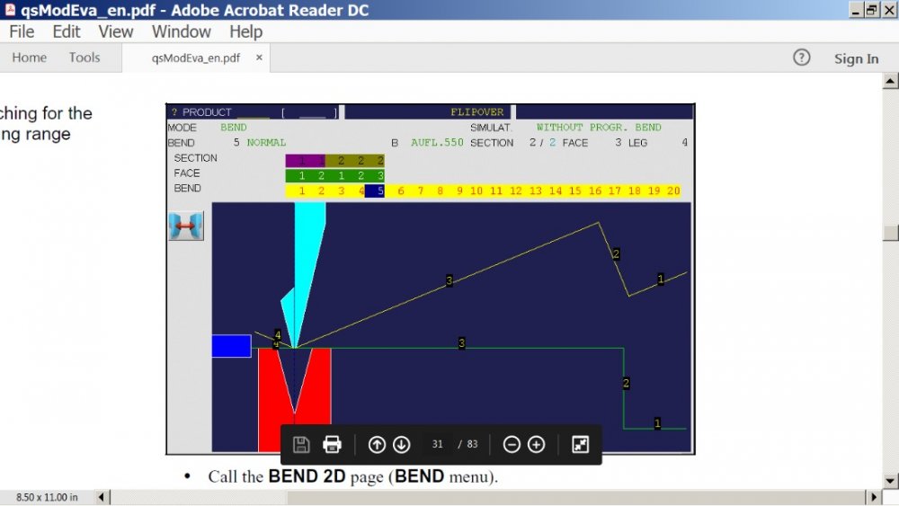
Reach the BEND 2D page
Example when you want to reach the
BEND 2D page, press the function key BEND


 , then sélect BEND 2D or simply type 02 (or the number indicated next to the choice).
|
Rapid validation |
To facilitate the operator’s work, the DNC |
|||||||||||
|
memorizes the last choice made in a menu. |
||||||||||||
|
To validate faster an option of a menu, just |
||||||||||||
|
double press on a function key (e.g.: |
), to |
|||||||||||
|
directly validate the last selected page. |
PAGE 8 2D REFERENCE MANUAL MODEVA/DNC 880S

Software conventions, Windows version
In basic configuration, the Windows version uses the following colours:
|
Black |
Designates fixed information, designates fields |
|
etc. |
|
|
or |
|
|
fields accessible by the cursor which can be |
|
|
modified by the user. |
|
|
Blue |
Used for titles and headnotes. |
|
Bluish-grey |
Variable information. Not accessible by the |
|
cursor. |
|
|
Green |
Scrolling fields. Accessible by the user for |
|
choosing between several predefined options |
|
|
(see Scrolling lists above). |
This page has been left blank intentionally.
PAGE 10 2D REFERENCE MANUAL MODEVA/DNC 880S

DEFINITIONS
ABS
Page: BEND NUMERICAL
This round robin list is placed next to the name of the axis of the X stop. Two choices: ABS and REL.
ABS indicates that the X axis functions in absolute mode.
This means that the destination of the axis is an absolute distance measured from the die V.
Absolute mode is selected by default.
|
See REL below. |
|||
|
Example: |
MEM |
POS |
|
|
X |
ABS |
190.00 |
120.00 |
REL
REL indicates that the X axis functions in relative mode.
This means that the displacement programmed is made departing from the actual stop position.
Generally a negative value is programmed.
The relative mode is often used with the cycle repetition (CY 2 at 99). For example with a punching tool, you wish to make 5 holes equidistant of
30.00mm. The first sequence must be in absolute mode (location of the first hole. The second sequence will be programmed in relative mode
(X REL 30.00) with a cycle repetition equal to 4 (CY 4).
|
Example: |
MEM |
POS |
|
X REL |
70.00 |
120.00 |

Remark: It is not possible to use the relative mode on the first sequence. If such is the case, an error is generated when changing mode (AUTO, SEMI-AUTO) and the message DEPL. X REL.
IMPOSSIBLE is displayed in the interactive field.
ACTIVE PERIPHERALS
Page: WELCOME
Aim:
This function allows to choose the peripheral containing the required information and this separately for the machine parameters, the products, the tools the CAD files and the complementary files on the product information page.
It offers a multitude of combinations especially appreciated on a PC work station. Effectively using these choices, the operator could easily manage several machines.
The comprehension of this notion is important, as its flexibility allows a large diversity of choice.
Definition:
The active peripheral is the peripheral in which the software is going to read, search, save or delete data. The active peripherals are designated on the
WELCOME page.
On certain pages, another peripheral can be temporarily selected for an operation (for ex. PRODUCT LIST, PROGRAMMING PUNCHES / DIES, TRANSFER).
Active Peripherals Machine
When you change the peripheral in the MACHINE field, automatically PRODUCTS, PUNCHES and DIES are redirected on to the same peripheral.
To change them independently one from the other, you must simply modify them afterwards.
The CAD FILES and COMPLIMENT peripherals are not modified automatically, as they are generally situated on a network and are often the object of a “specific classification” in one or several directories.
By modifying in this way the MACHINE peripheral, the environment of the software “ becomes” that of another machine. It is thus easy to simulate products for different configurations of pressbrakes.
Also, more and more you will find diskettes containing examples of special products (supplied by CYBELEC or by the machine manufacturer) for which the realization needs a special (Tools for example). With this possibility you can thus easily visualize these demonstrations with all the machine context in which they were created.
On a numerical control, it is evidently only possible to work with a machine when the MACHINE field is switched to INTERNAL.
If another peripheral is used to visualize a demonstration product for example, it will however still be possible to switch the DNC to semi-auto or auto mode.
PAGE 12 2D REFERENCE MANUAL MODEVA/DNC 880S

However the massage ENC NOT CONNECTED will appear and it will not be possible to work with the machine.
To reactivate the INTERNAL machine peripheral, you must: Select MACHINE INTERNAL.
Initialize the ENC by pressing INIT ENC, Action menu.
Active Peripheral Products
Selects the default peripheral in which the operations of searching, saving and deleting of products is effectuated.
Active Peripheral Punches / Dies
Selects the default peripheral in which the operations of searching, saving and deleting punches and dies is effectuated.
Evidently the tools specified in the current product must be available in the addressed peripheral, without which the software will give an error message.
ADMISSIBLE FORCE APPLIED TO THE DIES
Page: PROGRAMMING OF DIES
The maximum admissible force is defined when programming the tools. In reality however, the admissible maximum force varies depending on the bending angle (and, of course, on the other customary parameters).
The die programming page contains two pairs of fields which make it possible to adapt the safety parameters.
The fifth field enables the user to test the result.
When only the first Ton/m field is programmed, this means that the pressure limit is constant and not depending on the angle.
|
__._° |
-> |
max |
200.0 Ton/m |
|
__._° |
-> |
max |
___._ Ton/m |
|
Test 90.0° |
= |
200.0 Ton/m |
The Test field indicates the maximum admissible force for the programmed angle.
When the fields «open angle»  and Ton/m on the same line have been programmed, the calculation of the admissible force is limited according to the diagram shown below.

If there is no specific indication given by the manufacturer, you enter the maximum admissible force already known, and an «open angle» of 90° (as below).
|
90.0° |
-> |
max |
200.0 Ton/m |
|
__._° |
-> |
max |
___._ Ton/m |
|
Test 60.0° |
= |
115.5 Ton/m |
When the 4 fields have been programmed, the calculation of the admissible force is limited according to the diagram below. The choice between the above method and the method explained in this paragraph depends on the known data and the decision of the person who enters the die data.
|
90.0° |
-> |
max |
200.0 |
Ton/m |
||
|
30.0° |
-> |
max |
45.0 |
Ton/m |
||
|
Test 60.0° |
= |
122.5 |
Ton/m |
|||
PAGE 14 2D REFERENCE MANUAL MODEVA/DNC 880S

ALPHANUMERIC FIELDS
Certain fields (DRAWING, PUNCH, DIE etc.) can contain alphanumeric characters.
To program the alphanumeric fields on the numerical controls, you must use the «soft» alphanumeric keyboard.
To call the «soft” alphanumeric keyboard in the software , position the cursor on the alphanumeric field (if the field is only numeric the keyboard will not
appear) and press the 


 key.
key.
4 tables of characters are available (#1, #2, #3 and Alt). To change the «table»:
Point to the field bottom left #1, #2, #3 or Alt and press 


 or click left in this field.
To enter the characters in to the alphanumeric field:
Select the character.
|
Press |
or click left. |
||||||
Repeat the operation for the other characters.
To leave, press the 


 key again.

ANGLE CORRECTIONS
Pages: CORRECTIONS
GENERAL REMARKS
The sheet metals used in the workshops have hardly ever their nominal thickness. The real thickness commonly varies ±10% from the nominal value. Also the variation is not constant across the whole length of the sheet. The thickness on the left side can be different to the thickness on the right side (sheets with a trapezoidal section). The software allows to correct this type of error by dissociating the correction of one extremity from that of the other extremity of the bend.
The bending depth calculations (as well as those for elongation, pressure and crowning) are based on the nominal thickness (that which is programmed in the THICKNESS field).
In this Angle corrections chapter we will deal with 3 types of correction: Direct corrections
Angular corrections
Corrections by measuring the sheet thickness.
Depending on the field in which it is entered, a correction can act on: The relevant bend (uniquely)
All the bends (with the same angle) situated on the same section (same profile)
All the bends (with the same angle) of the product (also on distinct sections)
DIRECT CORRECTIONS
To use direct corrections, the DNC must be in programming or semiautomatic mode and you simply enter a value in to the required field on the first table of the page. The number of the current bend is located at the top of the screen.
If the correction concerns the two sides of the beam, the same value for Y1 and Y2 must be entered.
It is also possible to correct the other axes, the PP, the bending force and the crowning according to the same principles.
PAGE 16 2D REFERENCE MANUAL MODEVA/DNC 880S
![]()
Direct corrections are additioned. This means that if there is a global correction for the product and a correction for a given bend is programmed, the final correction for this bend will be the sum of the two corrections.
ANGULAR CORRECTIONS
After having made a bend, the operator measures the angle obtained. The measured angular value is entered in to the ANGLE field. The DNC automatically calculates the correction to obtain the angle originally programmed. If after making the corrected bend, the angle is still not correct, simply enter the new measured angle value. In certain cases this operation may have to be repeated 2 or 3 times.
Attention, you must not intervene in the direct corrections table simultaneously with the angular corrections.
As for the direct corrections the corrections can be attributed to:
|
BEND |
Corrects only the current bend. |
|
|
SECTION _ |
Corrects all the angles of the specified section |
|
|
which have the same programmed value and the |
||
|
same tools. |
||
|
PRODUCT |
Corrects all the angles of the product which |
|
|
have the same programmed value and the same |
||
|
tools. |
||
The DNC must be in programming or semi-automatic mode.
Program the THICKNESS MEASUREMENT field in the following manner:
THICKNESS MEASUREMENT CENTRAL NONE MODE OLD MEASURE
Measure the angle obtained.
Introduce the measured value in to the ANGLE field under one of the columns BEND, SECTION or PRODUCT.
Test the result and redo if necessary.
See also the machine parameter COMPENSATION ELASTIC RETURN on the MATERIAL page. This parameter allows to correct in permanence an angle in a given plane.
CORRECTIONS BY THICKNESS MEASUREMENT
Correction by thickness measurement can be realized in several ways, but the principle remains identical. A system (or the operator) furnishes the DNC with the real measurement of the material. With these parameters, the DNC calculates the necessary correction.

The two main methods are:
Measuring at the TDC (Top dead center)
Measuring at the PP (Pinch point).
Measuring at the TDC The principle is that the measurement is made and entered in to the DNC while the machine is at the TDC.
The measurement is entered either conventionally using the keyboard, or by a RS232 link using an adequate instrument of measure, or otherwise by a system integrated at the stop.
Measuring at the PP In this case the measurement is made at the PP. Three possibilities are offered.
— Measurement by the beam.
— Measurement by the beam with die displacement.
— Measurement of the real PP by an external system.
As for the direct and angular corrections, it is possible to affect the correction to the current bend, to the section or to the whole product.
Also, with the correction in function of the measurement of the thickness, it is possible to differentiate the correction for each extremity of the bend. The choice is made using the round robin list CENTRAL or EXTREMITIES.
(See further on in this chapter for the use of this possibility).
Remarks: For technical reasons, you can only pass to programming mode during working (DNC in automatic mode and programming) if
NO THICKNESS MEASUREMENT has been selected. For technical reasons, the fields POS. SHEET and THICKNESS MEASUREMENT can no longer be modified in semi-automatic mode.
Measuring at the TDC
As described in the introduction to this chapter, the measurement is made when the beam is at the TDC.
Only the introduction of the measurement by the operator , such as the «standard» DNC software will allow, will be described in this paragraph. The DNC must be in programming or semi-automatic mode.
Proceed in the following way:
Program the THICKNESS MEASUREMENT field in the following way:
THICKNESS MEASUREMENT CENTRAL TDC MANUAL MODE BY BEND
PAGE 18 2D REFERENCE MANUAL MODEVA/DNC 880S

Measure the thickness very precisely (using a micrometer).
Enter the measured value in to the LEFT THICKNESS field of the PRODUCT, SECTION or BEND column depending on your needs. By only programming the LEFT THICKNESS field, the software assumes that the measurement is central.
Leave the field. Bend.
If the introduction is made in the
PRODUCT column:
—The measurement made by the operator on whatever bend will remain valid until the next measurement.
—The real thickness obtained is saved in association with the product.
—It is considered that the real thickness is the same for all the bends.
—At each new measurement, all the bends are re-corrected.
—If no measurement is made, the correction is made according to the last measurement saved.
SECTION
—The measurement made by the operator on whatever bend of the section will remain valid until the next measurement..
—The real thickness obtained is saved in association with the section to which belongs the bend on which it was made. It is valid for all the successive bends belonging to the same section.
—If a new measurement is made, all the bends of the relevant section are re-corrected.
—If no measurement is made, the correction is made according to a possible former measurement saved in association with that section.
Remark: This means that if any values are present in the SECTION column, they will be taken in to account and the values in the PRODUCT column will be ignored. If there are no values in the SECTION column, the values in the PRODUCT column, if they exist will be taken in to account.
BEND
—The measurement made by the operator on whatever bend is only valid for that bend. It will also be memorized.
—If no measurement is made, the correction is made according to a possible old measure memorized in association with that bend.
Remark: If any values are present in the BEND column, they will be taken in to account and the values in the SECTION and PRODUCT columns will be ignored. If there are no values in the BEND column, the values in the SECTION column, if they exist will be taken in to account. If only PRODUCT column contains any values, then it is these that will be taken into account.

Measuring at the PP
Only the measurement at the PP with the beam will be described in this chapter.
Principle:
The beam makes its usual approach (in semi-auto or automatic). When it reaches just before the theoretical PP, the DNC reduces the system pressure and «lands» freely on the sheet. The DNC detects the stopping of the beam and in this way allows the measurement of the sheet thickness.
It is evident that in this phase the sheet must not flex under the influence of the beam, otherwise the measurement will be falsified. The way in which this option functions will depend directly on the machine hydraulics, the speed when arriving on the sheet and the minimum force of the beam in this measurement phase.
It is obviously unthinkable that in this phase the beam be out of true, the measurement would then be totally false.
Ideally the product should be in the centre of the machine, have a bending length greater than 2/3 of the total length of the machine and be able to support the weight of the beam without flexing.
As for the other corrections the measurement can be made by product, section or bend, central or at the extremities depending on the choice made.
Before each use, a calibration must be done in order to gauge the whole.
Calibration
A calibration cycle is very similar to a measurement cycle.
Simple, the real thickness obtained is subtracted from the nominal thickness. This difference is memorized to be used later as a correction for the real thickness calculations.
Procedure:
Measure the sheet with a micrometer. Select CALIBRATION MODE.
Enter the values in the appropriate fields RIGHT THICKNESS and
LEFT THICKNESS of the CORRECTIONS page. Put the DNC into semi-auto mode.
Place the sheet at the centre of the machine and make a bend.
If the calibration cycle has been done correctly the differences between the real thicknesses measured and the reference values will be displayed in the lines LEFT THICKNESS and RIGHT THICKNESS, under the —AIM— column. They will remain there until the next calibration.
Select the required measurement mode MODE BY PRODUCT,
BY SECTION or BY BEND. From that moment on, during working, the measurement will be made according to the option chosen. See also the description of OLD MEASUREMENT mode which follows.
Remark: If the POS. SHEET field is not defined, it is supposed that the sheet is centred between the two rulers.
If the length of the sheet is not defined, it is supposed that it is equal to the distance between the two rulers Y1 and Y2 (machine parameters).
PAGE 20 2D REFERENCE MANUAL MODEVA/DNC 880S

Working with the correction MEASUREMENT AT THE PP
After having done the calibration, MODE BY PRODUCT, BY SECTION or BY BEND must be selected depending on whether you wish to effectuate a measurement by product, section or bend respectively.
OLD MEASUREMENT In this mode no new measurements are made. The old measurements memorized in association with the product, section or bend are conserved and used.
This mode is especially useful when working with a batch of sheets sufficiently homogenous. In such a case it is sufficient to proceed with a single thickness measurement during the first bend of the first product and to correct on the same basis thereafter. This allows to avoid the inevitable time loss associated with measuring. This work mode also applies in the case of working with groups of products, because the old measurements associated with the last product executed are recopied on to the following product.
PP TOLERANCE IN % OF THICKNESS
Page: MACHINE PARAMETERS / MATERIALS.
This field allows to define a maximum limit to the «dispersion» of the material when the thickness correction at the PP is being used. In cases where the thickness of the measured
sheet is superior or inferior to nn%, the bend will not be carried out and the system will issue a message to the operator.
See Corrections (Table).
THICKNESS CORRECTION FACTOR
Page: MACHINE PARAMETERS / MATERIALS.
This table allows to define a set of corrections according to the thickness variation when the thickness correction at PP is being used. The default value for this factor is 1.00.
If the user notes that for a given material, the software has a tendency of overcompensating (i.e. the beam goes too far down when the real thickness is less than the nominal thickness, or the beam does not go down far enough when the real thickness exceeds the nominal thickness) he enters a value between 0.99 and 0.0 in the respective angle range.
However, if the software does not compensate enough, the operator enters a value between 1.01 and 99.99.
See Corrections (Table).

INDEPENDENT THICKNESS CORRECTION Y1-Y2
The principle consists of furnishing or (using one of the methods described above) the thickness at each extremity of the bend. By means of this data and knowing the position of the sheet, the DNC will calculate a different correction for Y1 and Y2. This type of correction is particularly appreciated for bending sheets with a great bending length and an important variation in thickness.
For this to function, the machine parameters describing the position of the rulers, the machine width ,etc. must be programmed, otherwise an error message will appear.
The independent thickness correction Y1 Y2 can be used in conjunction with either the thickness measurement at the PP or the thickness measurement at the TDC. It will also function with the choice of correction by product, section or bend.
Thickness measurement at the TDC
Functioning is identical to that described in the Measurement at the TDC paragraph above, except that the position of the sheet and the thickness at each extremity must be programmed.
Select THICKNESS MEASUREMENT AT EXTREMITIES
Program the position of the sheet in the POSITION SHEET field and in the chosen column.
Introduce in the same column the sheet thickness measured at each extremity of the future bend.
Leave the field. Bend.
Thickness measurement at the PP
Functioning is identical to that described in the Measurement at the PP paragraph above, except that the position of the sheet must be programmed.
Select THICKNESS MEASUREMENT AT EXTREMITIES.
Program the position of the sheet in the POSITION SHEET field and in the chosen column.
Proceed as described in the Measuring at the PP paragraph above. Continue bending.
CORRECTIONS: SENSITIVITY BDC
Page: CORRECTIONS, field: SENSITIVITY BDC.
This field indicates which depth variation is necessary to obtain an angle variation of 1 (one) degree in the current sequence.
If this value is too small (e.g. < or = 0.05 mm), it is recommended to use a die with a wider V opening.
PAGE 22 2D REFERENCE MANUAL MODEVA/DNC 880S

AUXILIARY FUNCTIONS
The auxiliary functions can be programmed and used for various means by the manufacturers.
It is thus inappropriate to discuss them here, please ask the manufacturer of the machine for details of their functions.
BACKGAUGE RETRACTION
Page: BEND NUMERICAL
In certain situations it is necessary to disengage the back gauge during bending.
This field is automatically programmed when an automatic search for the bending range is made. This value can be modified after the simulation by the operator.
The retraction value is a relative value usually positive. If a negative value is programmed, this allows to execute a negative “retraction”, that is a displacement towards the die.
A minimum default retraction can be imposed in the machine parameters.
BEND
AT THE BOTTOM OF THE DIE
See Bottoming.
FINAL
See Special bends.
INTERMEDIATE
See Special bends.

SEQUENCE WITHOUT BEND
Page: BEND NUM
It can be useful for the operator to create a sequence which does not realize a bend, but executes the displacement of an axis or an auxiliary function.
Insert a supplementary sequence for this operation (see Inserting a Sequence).
On BEND NUM page, in the desired sequence, delete the angle and program a value Y1/Y2 greater than that of the pinch point.
When executing the product, the axes and auxiliary functions position themselves as normally, but when the operator gives a descent command, the beam will not descend. If the DNC is in automatic mode, the next sequence will be displayed, the axes position themselves on the new values and the beam will be waiting for a descent command, as usual.
In the case that the beam should not descend and the operator has directly programmed the Y1/Y2 values, it is to verify that these values are not greater than those of the pinch point.
BEND COUNTER
The WELCOME page displays the number of bends carried out since a given date. The counter is set to zero in our plant. When the first bend in automatic or semi-automatic mode is done, the counter starts running and the date is automatically written. This data can not be modified on-site.
BENDING FORCE
Page: BEND NUM
If the data concerning the length, the thickness, the sigma and the tools are known, this field is automatically calculated. It indicates the bending force (tonnage) needed for the bend.
This field can be reprogrammed as you require. However if the value entered is greater than the tool safety, an error message is generated in the interactive field. These safety controls are executed when changing the DNC mode (see Tools).
PAGE 24 2D REFERENCE MANUAL MODEVA/DNC 880S

BENDING ORDER
AUTOMATIC BENDING ORDER
The software can effectuate on demand an automatic search for the bending order. The result is conditioned by the «simulation criteria» that the operator can enter depending on his requirements according to the product to be produced (see Simulation criteria).
Enter the product data (see the manual User guide).
BEND 2D page, BEND 3D page. Choose the simulation criteria.
Position the cursor on the SIMULE field and select WITHOUT IMPOSED BEND.
Choose SEARCH BENDING ORDER in the action menu.
Depending on the complexity of the product, the software will furnish a complete solution, a partial solution, or no solution. See hereinafter Unbend Mode.
MODIFYING THE BENDING ORDER
This operation is preferable done on the BEND 2D page (with a 3D version, it is possible to realize this operation on the BEND 3D page. See also the
3D Reference manual).
Above: Initial situation.
Requested situation.

Select the sequence to be modified (

 or Pg Dn keys).
Place the cursor on the FACE field and enter the number of the face to be bent (3).
Place the cursor on the STOP field and enter the number of the stop (4). The software proposes the possible stops in the STOP PR field.
Select SIMULE BEND in the Action menu.
The sequence which bends the chosen face has been deleted.
The next sequence bends the same face (BEND 2). Change the stop if necessary.
«Move» to the sequence to be modified (BEND 3 with the 

 or
or
Pg Dn keys).
Place successively the cursor on the FACE field and enter the number of the face, then on STOP and enter the stop for this sequence (in this example FACE 1 and STOP 0).
PAGE 26 2D REFERENCE MANUAL MODEVA/DNC 880S
![]()
Select SIMULE BEND in the Action menu.
Proceed in the same way for other bends or to totally impose a simulation.
If you have mastered the numbering of the faces and stops, it is not necessary to simulate each bend. After having finished the introduction for sequence simply position the cursor on the SIMULE field, select WITH IMPOSED BEND and SEARCH BENDING ORDER in the Action menu.
UNBEND MODE
The unbend mode is useful when the software cannot find a solution for the bending order.
The unbend mode presents the finished product, the operator determines the bending order manually in the same way as described above, but by commencing with the last bend and going towards the first.
Below a simple example in which the product touches the table frame before the bend, however the sheet is put. The solution for this product is to create an intermediate bend. This solution is described in Special bends.
This section only shows how to use the unbend function.
In the 1st figure, the product touches at the last bend, in the 2nd figure it already touches at the 2nd bend.

Below are the data of the product (the die height is 50 mm).
In BEND 2D page, when asking to search a bending order, the message
Solution not found is displayed.
Select UNBEND mode.
The last bend is displayed, you immediately can remark the collision.
|
If a solution without collision is displayed, press the |
key and |
|||||
see if the software furnishes a solution. If no solution is proposed, that means that there is collision.
Program or change in the FACE field the different faces and see which possibilities exist.
|
Press the |
key to move in the previous sequence. |
|||||
If the software finds a solution, this will be displayed immediately as well as the other possible faces (field PR FACE = proposed face).
In unbend mode the proposed faces are displayed in the PR FACE field. So the operator can introduce one by one the proposed faces in the FACE field, in order to see the result.
PAGE 28 2D REFERENCE MANUAL MODEVA/DNC 880S
 Loading…
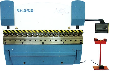
Гибочные пресса серии PSH предназначены для серийного, мелкосерийного и штучного изготовления сложных деталей имеющих большое количество гибов в разных плоскостях и под разными углами. Пресса оснащены современной панелью управления ЧПУ Cybelec DNC 880.
Функция автоматического захвата материала, подача материала, работа гибочного пресса, переворачивание заготовки и выполнение последующих операций За одну автоматическую операцию листовой металл становится изделием.
Заказать
Паспорт станка
ТЕХНИЧЕСКОЕ ОПИСАНИЕ КОНТРОЛЛЕРА CYBELEC DNC 880S PS:
- Конфигурируемое цифровое управление для X, Y1,Y2, R осей.
- Цветной TFT монитор (10-inch), 2D графика.
- Многоязыковое программирование в диалоговом режиме. В том числе русскоязычное.
- Программирование на машинном языке корректировок угла с вычислением глубины гибки в зависимости от материала и инструмента.
- Автоматическое преобразование: дюйм / мм; короткая тонна / метрическая тонна; фунтов на кв. дюйм х 1000 / кг/см2.
- Внутренняя энергонезависимая память
- RAM 256 MB,
- Compact Flash 1GB,
- Порты USB 1.1
- USB 1.1 (2x external 2x internal)
- порт принтера
- RS232
- RG45 Enternet
- VGA
- Оси, контролируемые контроллером X,Y1,Y2, R.
- Оси, контролируемые вручную Zl, Z2.
- В стандартную комплектацию также входит выносная педаль с кнопкой аварийного останова.
СТАНДАРТНАЯ КОНФИГУРАЦИЯ:
- Управление контроллером по четырем осям (Y1-Y2-X-R)
- Рабочий стол с гидравлической системой компенсации прогиба, управляемый ЧПУ
- ЧПУ CYBELEC DNC880S
- Высокоэффективная электрогидравлическая система пропорционального распределения давления
- Специальная система светодиодных датчиков Высокоэффективный сервопривод переменного тока и привод японского производства
- Уплотнения от попадания масла снаружи
- Высокоэффективный шестеренный насос с сетчатым фильтром
- Шариковый ходовой винт и линейная направляющая
- Стандартный комплект пуансон/ матрица (евро стандарт)
- Стандартная передняя поддержка листа
ОПЦИИ
- Система CYBELEC M0DEVA10S
- Система CYBELEC M0DEVA12S
- Блок с ЧПУ для управления осями Z1/Z2 (для DNC880S или более высокой версии)
Технические характеристики
| Модель | Усилие, тн | Длина гиба, мм | Вес, кг | Скорость опускания ножа, мм/сек | Скорость гиба, мм/сек | Скорость обратного хода, мм/сек | Ход ножа, мм | Мощность, кВт |
|---|---|---|---|---|---|---|---|---|
| PSH-40/1500 | 40 | 1500 | 3500 | 80 | 10 | 100 | 380 | 4 |
| PSH-50/2000 | 50 | 2000 | 4200 | 80 | 8 | 100 | 420 | 4 |
| PSH-63/2500 | 63 | 2500 | 6000 | 80 | 10 | 90 | 420 | 7,5 |
| PSH-63/3200 | 63 | 3200 | 6600 | 80 | 10 | 90 | 420 | 7,5 |
| PSH-80/2550 | 80 | 7200 | 7200 | 80 | 10 | 80 | 420 | 7,5 |
| PSH-80/3200 | 80 | 3200 | 7750 | 80 | 10 | 80 | 420 | 7,5 |
| PSH-100/2500 | 100 | 2500 | 8300 | 100 | 8,5 | 80 | 480 | 7,5 |
| PSH-100/3200 | 100 | 3200 | 9500 | 100 | 8,5 | 80 | 480 | 7,5 |
| PSH-100/4100 | 100 | 4100 | 11500 | 100 | 8,5 | 80 | 480 | 7,5 |
| PSH-100/5100 | 100 | 5100 | 14400 | 100 | 8,5 | 80 | 480 | 7,5 |
| PSH-125/2500 | 125 | 2500 | 8820 | 100 | 7,5 | 80 | 480 | 7,5 |
| PSH-125/3200 | 125 | 3200 | 10600 | 100 | 7,5 | 80 | 480 | 7,5 |
| PSH-125/4100 | 125 | 4100 | 12400 | 100 | 7,5 | 80 | 480 | 7,5 |
| PSH-125/5100 | 125 | 5100 | 15700 | 100 | 7,5 | 80 | 480 | 7,5 |
| PSH-160/2500 | 160 | 2500 | 9650 | 100 | 8,5 | 80 | 480 | 11 |
| PSH-160/3200 | 160 | 3200 | 11800 | 100 | 8,5 | 80 | 480 | 11 |
| PSH-160/4100 | 160 | 4100 | 13800 | 100 | 8,5 | 80 | 480 | 11 |
| PSH-160/5100 | 160 | 5100 | 17620 | 100 | 8,5 | 80 | 480 | 11 |
| PSH-200/2500 | 200 | 2500 | 10220 | 100 | 10 | НО | 520 | 18,5 |
| PSH-200/3200 | 200 | 3200 | 13000 | 100 | 10 | НО | 520 | 18,5 |
| PSH-200/4100 | 200 | 4100 | 15000 | 100 | 10 | 110 | 520 | 18,5 |
| PSH-200/5100 | 200 | 5100 | 20520 | 100 | 10 | 110 | 520 | 18,5 |
| PSH-200/6100 | 200 | 6100 | 25100 | 100 | 10 | 110 | 520 | 18,5 |
| PSH-250/2500 | 250 | 2500 | 12850 | 100 | 8,5 | 95 | 520 | 18,5 |
| PSH-250/3200 | 250 | 3200 | 15000 | 100 | 8,5 | 95 | 520 | 18,5 |
| PSH-250/4100 | 250 | 4100 | 18000 | 100 | 8,5 | 95 | 520 | 18,5 |
| PSH-250/5100 | 250 | 5100 | 25030 | 100 | 8,5 | 95 | 520 | 18,5 |
| PSH-250/6100 | 250 | 6100 | 30000 | 100 | 8,5 | 95 | 520 | 18,5 |
| PSH-320/3200 | 320 | 3200 | 19800 | 100 | 7,2 | 100 | 520 | 22 |
| PSH-320/4100 | 320 | 4100 | 22800 | 100 | 7,2 | 100 | 520 | 22 |
| PSH-320/5100 | 320 | 5100 | 28600 | 100 | 7,2 | 100 | 520 | 22 |
| PSH-320/6200 | 320 | 6200 | 33600 | 100 | 7,2 | 100 | 520 | 22 |
+7 (495) 215-16-67
8 (800) 333-16-67
с 9:00-19:00 — ежедневно (МСК)
Заказать звонок
×
Обратный звонок
Представьтесь
Номер вашего телефона
Ваш вопрос
я даю согласие Shopozz на обработку персональных данных
в соответствии с Федеральным законом от 27.07.2006 года №152-ФЗ «О персональных данных», на условиях и для целей, определенных Политикой конфиденциальности.
×
Доставка товаров с аукциона eBay и интернет-магазинов США в
Россию (Москва, Санкт-Петербург, Новосибирск, Екатеринбург,
Казань, Нижний Новгород, Челябинск, Красноярск, Самара, Уфа,
Ростов-на-Дону, Омск, Краснодар, Воронеж, Волгоград, Пермь и
другие города).
© Shopozz — сервис покупок за рубежом
Швейцарская компания Cybelec специализируется на разработке и поставке числовых систем управления для станков, работающих с листовым металлом. Гибочные прессы, гильотинные ножницы оснащаются цифровыми блоками, обеспечивающими последовательное выполнение рабочих операций. Программное обеспечение позволяет автоматизировать процессы, моделировать гибку, корректировать конфигурацию осей станка в соответствии с технологическими потребностями. Числовые контроллеры DNC представлены во многих версиях, рассчитанных на выполнение широкого круга задач.
Системы ЧПУ линейки DNC
Одно из ключевых достоинств числовых систем DNC от Cybelec состоит в сочетании простой эксплуатации, высокой эффективности и стабильности работы электронных устройств. Именно это стало причиной неизменного спроса на продукты программного управления. Постоянно оптимизируя предыдущие решения, компания предлагает более новые, усовершенствованные системы. Поэтому управление станками становится все более удобным, наглядным, результативным. Среди стандартных, проверенных временем систем можно отметить следующие:
- DNC 10 – консоль для гильотинных ножниц;
- Cybelec DNC 60 – числовой контроллер для гибочного пресса или ножниц для резки металла;
- DNC 880S – высокопроизводительный цифровой контроллер для гибочных приложений;
- DNC 1200 – графический управляющий блок для гибки листового металла;
- DNC 400 – консоль для обычных прессов.
Некоторые из перечисленных выше ЧПУ в настоящее время сняты с производства. Тем не менее по заявке потребителей компания обеспечивает техническую поддержку цифровых устройств. Высокое качество продуктов, их надежность позволяют успешно использовать системы намного больше эксплуатационного ресурса, гарантированного производителем. Ниже приводится краткая характеристика наиболее востребованных ЧПУ.
Числовая система DNC 60
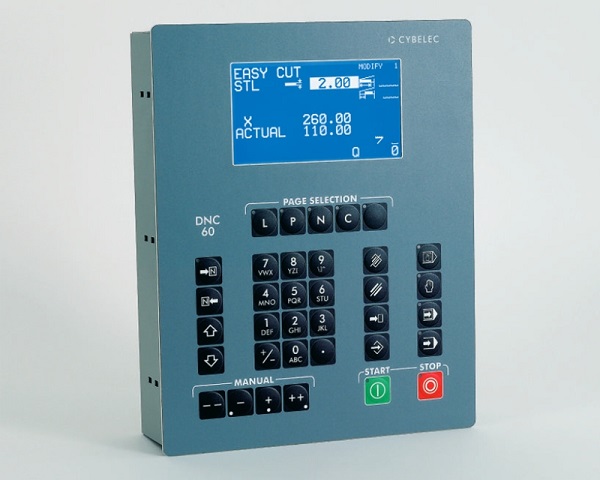
Цифровой контроллер DNC 60 предназначен для различных целей. В зависимости от программного обеспечения система ЧПУ может использоваться для синхронизированных и несинхронизированных прессов с подвижным верхом или приводимыми инструментами, а также для управления ножницами для резки металла. Простота программирования позволяет производителю настраивать конфигурацию осей станка, входов/выходов и вспомогательных функций в соответствии со своими потребностями.
Числовая система способна выполнять двухмерное моделирование, обеспечивать прямое программирование угла гибки, автоматически вычислять BDC. ЧПУ оснащено 5,5-дюймовым цветным монитором, водонепроницаемой и стойкой к загрязнениям клавиатурой. Конфигурация страниц позволяет выполнять быструю коррекцию параметров.
Числовая система DNC 1200
Консоль Cybelec DNC 1200 оснащена TFT-экраном, обеспечивающим непревзойденный визуальный комфорт. Установленная под экраном, слегка наклоненная клавиатура с большими клавишами способствует быстрому вводу данных, даже когда оператор в перчатках. Система числового управления спроектирована таким образом, чтобы можно было использовать такие носители, как CD-ROM, Zip-накопители и другие современные средства. ETC-секция (Исполнительное числовое управление), которая управляет функциями машины, расположена в электрическом шкафу. Такая конструкция обеспечивает большую гибкость с точки зрения модульности и интеграции.
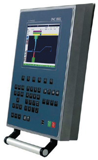
Числовая консоль DNC 880s

ЧПУ Cybelec DNC 880s работает под управлением операционной системы Windows XP и разработана специально для обработки листового металла. В зависимости от программного обеспечения применяется для управления синхронизированными прессами и прессами с механической или гидравлической скоростью. Панель оснащена 10-дюймовым TFT-монитором с большими клавишами и 2D дискретным программным обеспечением, что гарантирует удобство ее использования.
Числовая консоль обладает компактными габаритами и может изготавливаться в двух версиях: с количеством осей от 4 до 7. Среди основных достоинств можно отметить высокоточную и быструю настройку, удобный интерфейс, повышенную производительность, расширенную функциональность, простое и понятное программирование.