-
Contents
-
Table of Contents
-
Bookmarks
Quick Links
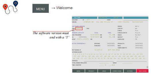
User Manual
for Synchronized Press Brakes
Sept14
V3.1
Related Manuals for CYBELEC CybTouch 12
Summary of Contents for CYBELEC CybTouch 12
-
Page 1
User Manual for Synchronized Press Brakes Sept14 V3.1… -
Page 2
© 2014 Cybelec S.A. All Rights Reserved Copying, reproduction, modification, distribution, display or transmission of any of the contents of this manual for any purpose without the prior consent of Cybelec S.A. is strictly prohibited. -
Page 3: Table Of Contents
Signs and Icons appearing in this Manual ……………… 2 General warning ……………………..2 Information………………………. 2 Settings ……………………….2 Navigation ………………………. 2 Getting started with CybTouch 12 …………….3 General navigation ……………………4 Menu Button ……………………..4 Status Pages Zone ……………………… 4 Screen Cleaning ……………………..4 Status page ……………………….
-
Page 4
Computer ID …………………………12 Option list ………………………….12 New option code ………………………..12 USB Transfer ……………………..13 Importing parts from other Cybelec NCs …………………13 Basic Page Description ………………14 Bend Numerical Page …………………… 14 More Page ……………………… 14 Available functions on the More page ………………..15 Material …………………………..15… -
Page 5
The Intuitive Programming Opening (TDC) …………………………17 Crowning ……………………………17 Back gauge finger type ………………………17 Number of parts ………………………..17 Back gauge manual control ………………………17 Tools Management ………………..18 Punches ……………………….18 How to create or modify a punch? …………………19 Dies ………………………… 20 How to create or modify a die? ………………….21 Naming Tools …………………….. -
Page 6
The Intuitive Programming Error and Warning Messages …………….. 32 Warning Messages ……………………32 Error Messages ……………………..35… -
Page 7
The Intuitive Programming… -
Page 8
The Intuitive Programming… -
Page 9: Safety
CybTouch 12 PS User Manual afety eneral afeTy The users must have , but most of all must ndeRstood espect directives described in this manual. All people coming into contact with the machine on which the numerical control is installed, whatever their function or whatever state the machine is in…
-
Page 10: Signs And Icons Appearing In This Manual
CybTouch 12 PS User Manual iGnS and conS appearinG in ThiS anual While using this manual, you will come across the signs and icons represented here below: they are directly related to the safety and security of persons. Carefully follow this advice and inform others about it.
-
Page 11: Getting Started With Cybtouch 12
CybTouch 12 PS User Manual ettinG Started with ouCh Depending on software evolutions and the press brake controlled by the CybTouch (configuration/capabilities), the present manual may not fully correspond to the CybTouch that you currently have. However, differences are only minor.
-
Page 12: General Navigation
CybTouch 12 PS User Manual eneral naviGaTion Add step Screen Cleaning button or next step Status Pages Zone Menu Button Menu Button The Menu button allows you to directly select (jump to) the desired screen. The content of the menu changes contextually.
-
Page 13: Status Page
CybTouch 12 PS User Manual TaTuS paGe The Status page shows the status of all inputs and outputs and axes positions of the NC. This feature is very useful during setup or during phone service with a machine installed in the field.
-
Page 14: Language
CybTouch 12 PS User Manual Language To browse through the available languages, simply touch Language on the screen. Available languages are: • English. • Deutsch. • Nederlands. • Brazil. • Español. • Türkçe. • • Français. • 中文. 台灣. •…
-
Page 15: Materials
CybTouch 12 PS User Manual Materials Touching Materials opens the Materials page, where the default characteristics for each material can be changed, or a new material can be configured. This page may not be available, depending on the machine parameters’…
-
Page 16: Clear Indexation
CybTouch 12 PS User Manual Clear indexation When activated, this function clears the index and the machine will search for them, as it does when turning the power on, allowing the operator to re-index its machine without turning it off.
-
Page 17: Brightness Xx% Eco Xx
CybTouch 12 PS User Manual Brightness xx% Here the brightness of the screen for normal mode and Eco mode can be defined: Eco xx% 1. Touch the mode for which you want to modify the brightness. 2. Use the buttons to set the brightness.
-
Page 18: Service Page
CybTouch 12 PS User Manual ervice Button) → Other menus → Service → Service (Menu Set Axis Allows the operator to manually adjust the position of the back gauge (axes X and R) and the beam (axes Y1 and Y2).
-
Page 19: Defrag
CybTouch 12 PS User Manual Defrag This function will rearrange the memory space of the CybTouch. Simply touch it and follow the instructions given in the yellow pop-up window. Format This function will erase all data in the CybTouch. Only use this with the help of a technician.
-
Page 20: Configuration Options
CybTouch 12 PS User Manual Configuration Touching this menu opens the following page, where one can find the computer’s identification and manage the machine’s options. options Button) → Other menus → Service → Service → Configuration options (Menu Serial number This is the serial number of the CybTouch.
-
Page 21: Usb Transfer
Return to User Preferences Transfer button Importing parts CybTouch 12 is delivered with Cybelec’s off-line software PC1200, which controls most of the other numerical controls produced by Cybelec. from other Cybelec NCs From version S1, PC1200 includes CybTouchConverter, which allows you to convert parts to the CybTouch format, and import them into your machine with the above mentioned function.
-
Page 22: Basic
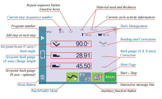
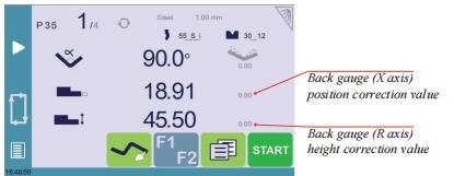
CybTouch 12 PS User Manual aSiC eSCriPtion uMerical Repeat sequence button Material used and thickness (inactive here) Current step (sequence) number Current cycle activity information Program number Tools Management Add step or next step Bend Correction Beam (Y axis) position value / bend angle Back gauge (X &…
-
Page 23: Available Functions On The More Page
CybTouch 12 PS User Manual Available The More page displays parameters related to the part, and depending on the CybTouch configuration and the type of action performed, it also displays various settings for the functions on the current bend. More page Material This is not a sequence parameter, but of course a part parameter.
-
Page 24: Step Bending
CybTouch 12 PS User Manual Step bending When a large radius bend has been programmed (see L-Alpha Mode, page 27), its parameters are displayed here. It is possible to modify them directly here. Programming 99 x will automatically calculate the maximum possible step bends. The resulting value may be reduced.
-
Page 25: Opening (Tdc)
CybTouch 12 PS User Manual Opening (TDC) For parts created with a profile (see TouchProfile Mode L-Alpha Mode), this value is automatically calculated to allow the operator enough room to extract its bent part from between the tools. It is however possible to change it manually.
-
Page 26: Tools Management
CybTouch 12 PS User Manual oolS anaGeMent Tools management allows the creation and configuration on the CybTouch of the tools to be used on the machine. These tools are then taken into account in bend calculations. Once a punch and die are created and selected, you can select the bend angle you require as well as the flange length (L).
-
Page 27: How To Create Or Modify A Punch
CybTouch 12 PS User Manual How to create or If no punch is yet created, the punch will have no name (??? is displayed). If a punch already exists, then the last punch used will be selected, here 60_N (modifications will modify a punch? not alter the existing punch as they will be saved under another name).
-
Page 28: Dies
CybTouch 12 PS User Manual → Bend Numerical Page Die mounting direction Die name Browsing through existing dies Basic die data Bottoming Return to Bend Numerical Page Die more specific data Touch the die to display its default shape, allowing…
-
Page 29: How To Create Or Modify A Die
CybTouch 12 PS User Manual How to create or If no die is yet created, the die will have no name (??? is displayed). If a die already exists, then the last one used will be selected, here 30_12 (modifications will not alter the modify a die? existing die as they will be saved under another name).
-
Page 30: Naming Tools
CybTouch 12 PS User Manual aMinG oolS It is recommended that you use naming conventions for your tools. Below you will find a simple convention allowing you to precisely identify a punch or die through its name. Of course, depending on your needs you may need to create more rules for punch and die naming.
-
Page 31: Creating A Part Program
CybTouch 12 PS User Manual reatinG a roGraM There are three ways to create a program part: with the TouchProfile Mode, with the Numerical Mode (see page 26), and with the L-Alpha Mode (see page 27). In this chapter the machine is considered operational: machine parameters,…
-
Page 32: Automatic Bend Sequencing (Optional)
CybTouch 12 PS User Manual 5. Touch on an angle to modify its value. Touching the icon will open a yellow pop-up, in which it possible to: • Activate (and deactivate) a special Special tools Special tools tool by touching its icon, and select it from a list by pressing ???.
-
Page 33
CybTouch 12 PS User Manual Pressing the back button will erase the last bend in the sequence. If you wish to delete all bends, simply touch the button. 3. Immediately after determining the last bend to be selected, the Bend 2D screen here below is displayed. -
Page 34: Numerical Mode
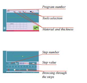
CybTouch 12 PS User Manual uMerical It is also possible to simply create a part program directly on the Bend Numerical Page. Current step (sequence) number Material used and thickness Program number Tools selection Add step or next step Angle of the bend…
-
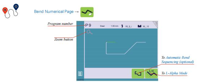
Page 35: L-Alpha Mode
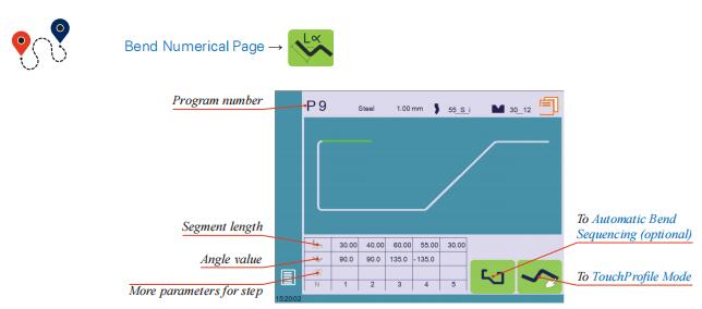
CybTouch 12 PS User Manual lpha → → Bend Numerical Page Bend Numerical Page Program number Automatic Bend Segment length Sequencing (optional) Angle value TouchProfile Mode More parameters for step This page is only available if user preference Show page L-alpha num (see page 6) is set to yes.
-
Page 36: Bend Correction
CybTouch 12 PS User Manual 7. A yellow pop-up is displayed, in which Special tools Special tools it possible to: Max. distance to Max. distance to • Activate (and deactivate) a special ideal curve ideal curve tool by touching its icon, and select it from a list by pressing ???.
-
Page 37: Crowning
CybTouch 12 PS User Manual etting nStructionS 1. Touch the angle correction icon, and enter the physically measured Reset corrections button Reset corrections button value of the angle. The numerical control will automatically calculate the Y1 and Y2 axes corrections.
-
Page 38: Saving And Loading A Program
CybTouch 12 PS User Manual avinG and oadinG a roGraM avinG a roGraM After creating a program, an operator can save the program in order to use it again: 1. In the Bend Numerical Page, touch the Program number (e.g. P0).
-
Page 39: Easybend Page
CybTouch 12 PS User Manual Button) → EasyBend (Menu The EasyBend page is used for individual bends, for example when an external worker needs to interrupt production just to make a single bend (usually with the same tools). The program currently being used for production is only temporarily interrupted (no need to save it) when switching to the EasyBend page, and then resumed →…
-
Page 40
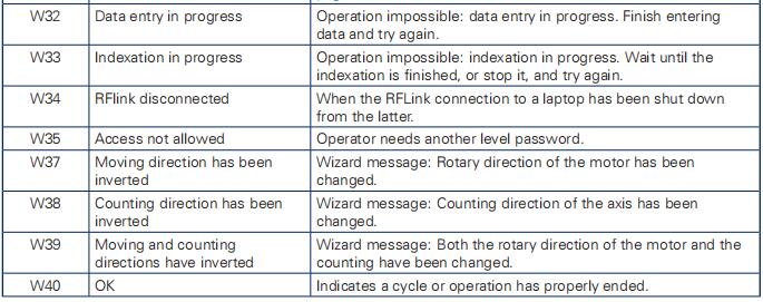
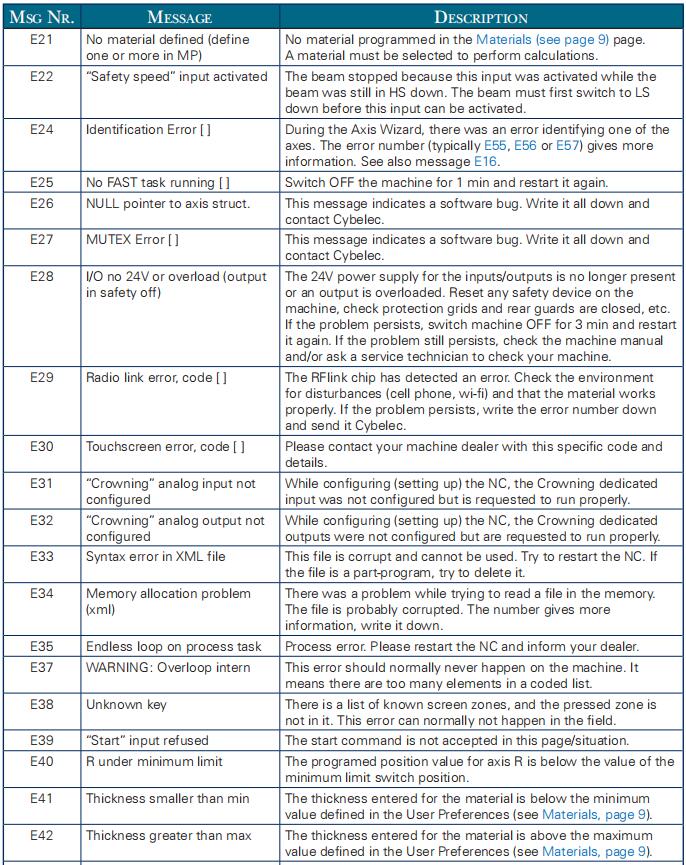
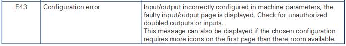
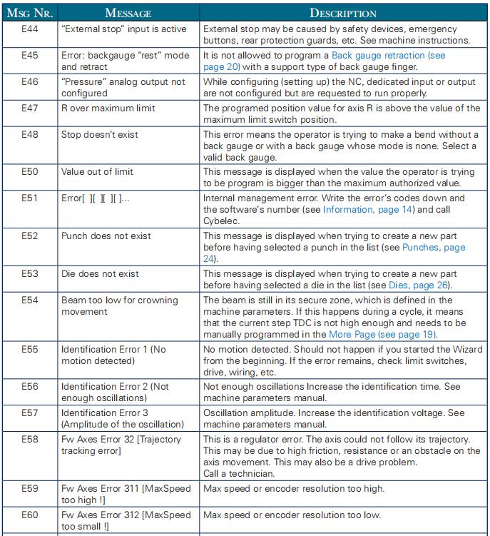
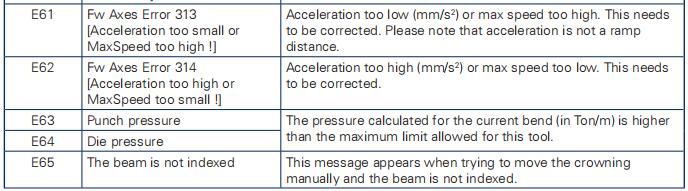
CybTouch 12 PS User Manual rror and arninG eSSaGeS Following is a list of warning and error messages which may be displayed on the interactive message line of the CybTouch. There are two types of messages: • Warning Messages, which are displayed on a green background. -
Page 41
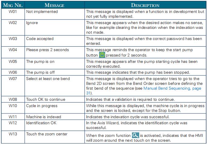
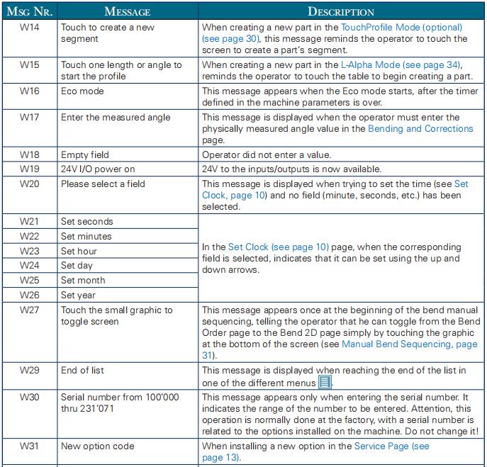
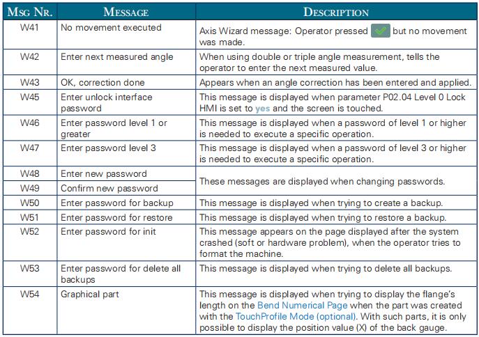
CybTouch 12 PS User Manual eSSaGe eScripTion Touch the zoom center When the zoom function is activated, indicates that the HMI will zoom around the next touch on the screen. Touch to create a new When creating a new part in the… -
Page 42
CybTouch 12 PS User Manual eSSaGe eScripTion Moving and counting Wizard message: Both the rotary direction of the motor and the directions have inverted counting have been changed. Indicates a cycle or operation has properly ended. No movement executed Axis Wizard message: Operator pressed but no movement was made. -
Page 43
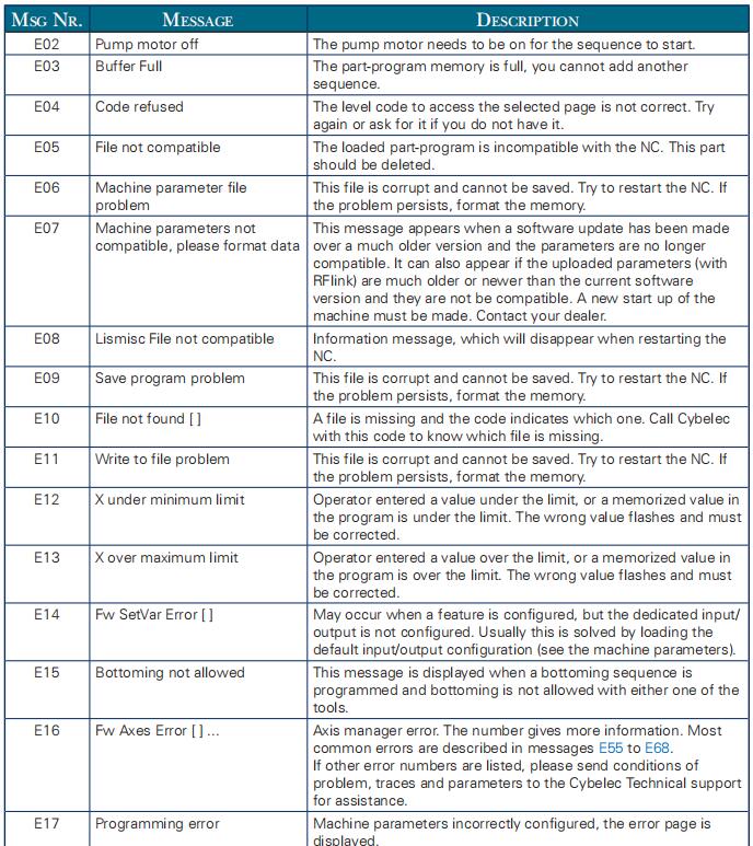
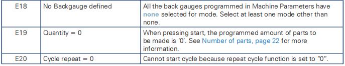
This file is corrupt and cannot be saved. Try to restart the NC. If the problem persists, format the memory. File not found [ ] A file is missing and the code indicates which one. Call Cybelec with this code to know which file is missing. Write to file problem This file is corrupt and cannot be saved. -
Page 44
CybTouch 12 PS User Manual eSSaGe eScripTion No material defined (define No materials programmed in the Material pages (in User one or more in MP) preferences). A material must be selected to perform calculations. Identification Error [ ] During the Axis Wizard, there was an error identifying one of the axes. -
Page 45
CybTouch 12 PS User Manual eSSaGe eScripTion Error: backgauge “rest” mode It is not allowed to program a Back gauge retraction (see and retract page 15) with a support type of back gauge finger. “Pressure” analog output not While configuring (setting up) the NC, dedicated input or output configured are not configured but are requested to run properly. -
Page 46
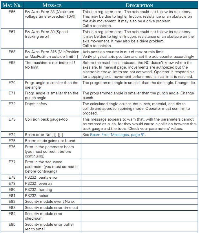
CybTouch 12 PS User Manual eSSaGe eScripTion The machine is not indexed ! Before the machine is indexed, the NC doesn’t know where the No limit axes are. In manual page, movements are authorized but the electronic stroke limits are not activated. Operator is responsible for stopping axis movement before mechanical limit is reached.
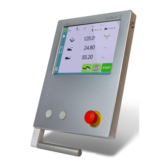
CybTouch 12

ОСОБЕННОСТИ
— Простой интерфейс, интуитивно понятный оператору, полностью реализованный на сенсорном экране.
— Увеличенная производительность и точность расчета
— Мощный инструментарий для удобной работы и получения качественного изгиба
БРОШЮРА
ТЕХ. ХАРАКТЕРИСТИКИ
Инструкция по эксплуатации CybTouch 12PS (образец)
Полная версия инструкции предоставляется по запросу с указанием модели станка и производителя.

CT12-1

CT12-5

CT12-4

CT12-2

CT12-3
CybTouch 12 Controller Manual for CNC Press Brake
Part 1 — Safety
General Safety

The users must have Read and Understood, but most of all must Respect thedirectives described in this manual. All people coming into contact with the machine on which the numerical control is installed, whatever their function or whatever state the machine is in (assembly, disassembly, start-up, production, maintenance, repairs) must have read and understood the requirements concerning the security and the entirety of the directives of operation described in the manuals delivered with the machine.

The operator must be properly trained to work with the machine on which the numerical control is installed. Improper use of the numerical control can cause heavy damage on equipment and/or
injuries to people.
Modification of machine parameters can cause important material damage or lead to irregular product quality. Do not expose the numerical control to excessive humidity so as to avoid any risk of electrocution and any deterioration of the equipment. Make sure the numerical control is disconnected from the mains power before carrying out any cleaning. Do not use liquids based on alcohol or ammoniac. In case of malfunction of the numerical control, call a technician. Do not expose the numerical control to direct sun rays or any other heat source. Do not place the numerical control in the neighborhood of magnetic equipment such as transformers, motors or devices which generate interference (welding machines, etc.)
Signs and Icons Appearing in This Manual
While using this manual, you will come across the signs and icons represented here below: they are directly related to the safety and security of persons. Carefully follow this advice and inform others about it.
- General warning
This warning sign appears in the manual whenever it is necessary to pay attention torules, instructions or advice. The correct sequence of operations is to be followed in order to avoid damage to the machine. It symbolizes a serious personnel danger.
- Information
This warning sign appears in this manual whenever an important information needs to be taken into consideration. Pay attention to this sign and follow the instructions given.

- Settings
This sign appears in this manual whenever setting instructions are given. Pay attention to this sign and follow the sequence of instructions given.

- Navigation
This icon appears in this manual to give navigation information, to give the path to the subject treated in the chapter.
Part 2 — Getting started with CybTouch 12
Depending on software evolutions and the press brake controlled by the CybTouch (configuration/capabilities), the present manual may not fully correspond to the CybTouch that you currently have. However, differences are only minor.
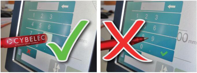
Touchscreens are pressure sensitive. Do not press down hard on the screen. Pressing hard on the screen will damage the display.Such damage is not covered by manufacturer warranty!
Do not use sharp and/or pointed objects (sheet metal, screwdriver, metal pen ball, etc.) to touch the screen; only use your fingers (with or without gloves on) or a plastic pen. Make sure that your gloves do not have metal particles encrusted in the finger tips as they may also damage the screen.
Take a few minutes to practice pressing gently on the screen, you will find that the screen is very reactive and it is pleasant to use.
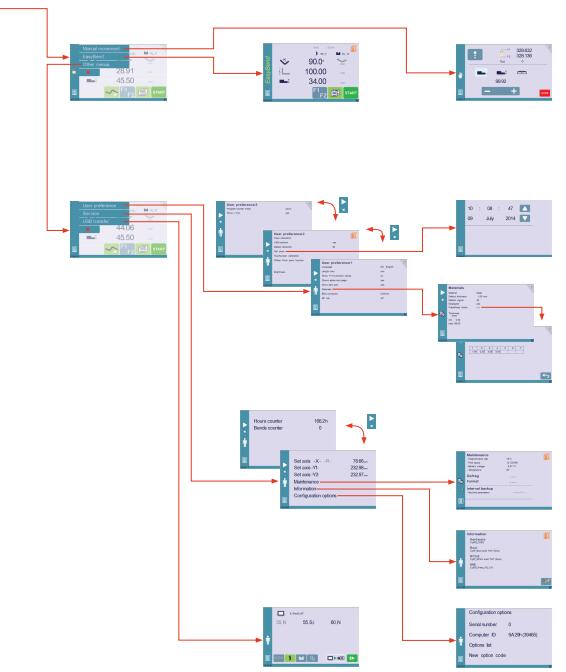
Screen Map
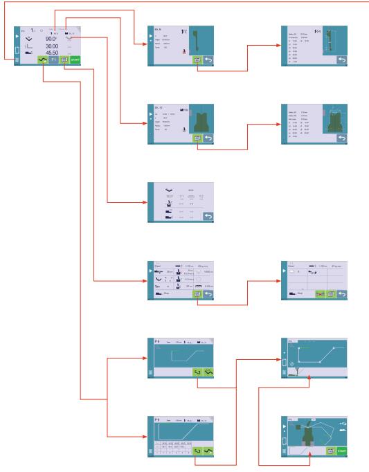
Screen Map (continued)
General navigation
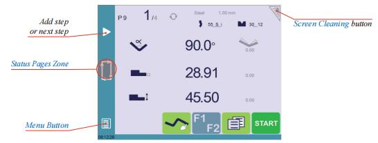
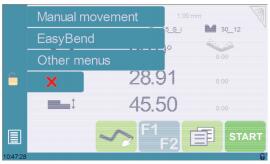
Menu Button
The Menu button ![]() allows you to directly select (jump to) the desired screen. The content of the menu changes contextually.
allows you to directly select (jump to) the desired screen. The content of the menu changes contextually.
Status Pages Zone
The Status pages zone gives access to the Status page (see page 7). This is really a zone that is active at any moment from any page.
Screen Cleaning
To clean the screen while the CybTouch is on, touch the ![]() button. Use only a damp and smooth cloth with soap or a neutral detergent.
button. Use only a damp and smooth cloth with soap or a neutral detergent.
NEVER use solvent, petrol, benzene, alcohols, etc.
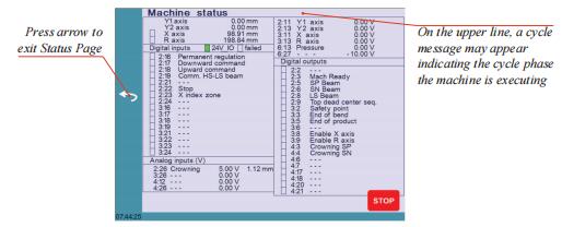
Status page
The Status page shows the status of all inputs and outputs and axes positions of the NC.
This feature is very useful during setup or during phone service with a machine installed in the field.
This page is accessed from anywhere by pressing the Status Pages Zone (see page 6).
To exit the Status page, press on the arrow on the left.
User Preferences
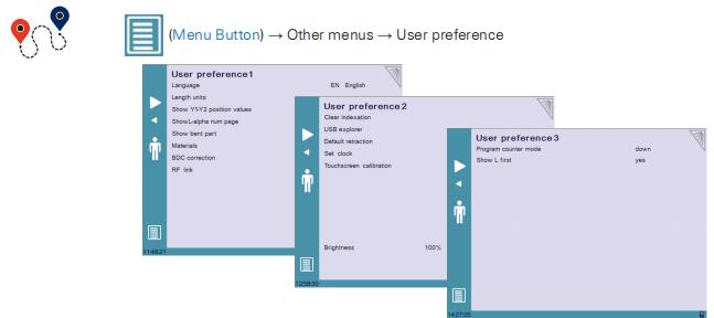
To exit the User Preference page, touch the ![]() button.
button.
Language
To browse through the available languages, simply touch Language on the screen. Available languages are:

The list of available languages is subject to change and may increase over time.
Length Units
This parameter allows choosing between mm, inch and none for the length unit to be used in the CybTouch.
When none is selected, the units used are millimeters.
Show axes position values
This function will display the axes positions on the Bend Numerical Page (see page 17).
• When set to no, the position of axis Y1 is displayed during the beam’s movements.
• When set to yes1, the positions of the axes are displayed during their respective movements.
• When set to yes2, the positions of the axes are constantly displayed under their respective set-point values.
Show page L-alpha num
When set to yes, this parameter gives access to the L-Alpha Mode (see page 34). This ![]() button is then displayed on the TouchProfile Mode page.
button is then displayed on the TouchProfile Mode page.
Show bent part
This parameter, when activated, lets the operator see the state of the part before and after the bend in the Automatic Bend Sequencing (optional) page.
Materials
Touching Materials opens the Materials page, where the default characteristics for each material can be changed, or a new material can be configured.
This page may not be available, depending on the machine parameters’ configuration. To be allowed to access the Materials page, a level 2 password is required.
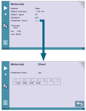
The Materials page displays:
• Material: Selected material (here Steel).
• Default thickness for the material.
• Default sigma: Default sigma for the material (here 45).
• Displayed: If the material will be available to be selected for use (here yes).
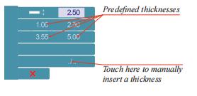
• Predefined thickn.: Allows defining up to 7 different predefined thicknesses for the selected material.
• Thickness min/max: Determines the maximum and minimum accepted thickness for the selected material.
Three predefined default materials are available (steel, stainless steel, aluminum), but others can be added.
To add a material:
1. Touch Material and select a non-configured material (Mater X) from the list.
2. Enter the new material’s characteristics.
3. Touch the name (Mater X) to display the keyboard and enter the name of the new material.
BDC correction
This parameter allows the operator to apply a permanent correction to the Bottom Dead Center position.
This correction is always applied and is NOT shown in the correction page. If you experience big differences from what you expect to get, maybe check the value of this parameter.
RFLink
When activated, this function allows communication between the CybTouch and a laptop computer, onto which Cybelec’s RFLink dongle is plugged in. This function’s default status is off, and it is automatically reset to off every time the NC is turned on.
Clear indexation
When activated, this function clears the index and the machine will search for them, as it does when turning the power on, allowing the operator to re-index its machine without
turning it off.
USB Explorer
When this parameter is set to yes, it is possible to browse the USB key from the USB transfer screen.
Default retraction
This parameter allows defining the default value displayed in the More Page(See page 19)when activating the back gauge retraction function.Set Clock Allows the user to set the time and date on the CybTouch.
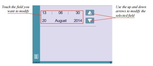
Set Clock
Allows the user to set the time and date on the CybTouch.
Touchscreen Calibration
As a tall operator will tend to touch higher than a smaller one on the screen, this function allows the calibration of the touch screen, and also makes sure that it is operating correctly.
Setting Instructions: Simply follow the instructions on the page to calibrate the touchscreen
Use your finger or the plastic tip of a pen to calibrate the Touchscreen. Never use sharp objects as this will damage the screen.
Offset Pinch Point function
When this parameter is set to yes, the Offset Pinch Point (see page 23) function is available on the More Page.
Brightness xx% Eco xx%
Here the brightness of the screen for normal mode and Eco mode can be defined:
1. Touch the mode for which you want to modify the brightness.
2. Use the ![]() buttons to set the brightness.
buttons to set the brightness.
Program counter mode
This parameter allows defining the counting mode of the part counter. When set to up, the counter will count up to the desired number. When set to down, the counter will count from the desired number down to 0.
Show L first
This function allows choosing the data entry mode for the back gauge on the Bend Numerical Page or EasyBend Page. When set to yes, the length of the flange icon ![]() is displayed by default. When set to no, the icon for the position in mm of the back gauge
is displayed by default. When set to no, the icon for the position in mm of the back gauge![]() is display
is display
Manual Axes Movement
In the course of setting up a machine, it is sometimes necessary to be able to move the axes manually, for example when changing the tooling. This can be done on this page.
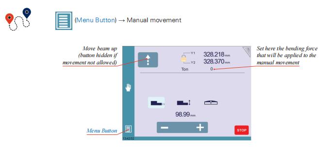
Setting Instructions:
1. Select the axis that you want to move:
• ![]() for the back gauge X axis.
for the back gauge X axis.
• ![]() for the back gauge R axis.
for the back gauge R axis.
• ![]() for the crowning axis.
for the crowning axis.
2. Touch the ![]() buttons to move the selected axis.
buttons to move the selected axis.
3. Use the foot switch (Low Speed Down movement) and this ![]() button (High Speed Up) to move the beam.
button (High Speed Up) to move the beam.
Desynchronized Beam
When the padlock is open![]() , it is possible to select and move (Low Speed Down movement) Y1 or Y2 only. This is an easy way to return an unsynchronized beam back to parallel to the table.
, it is possible to select and move (Low Speed Down movement) Y1 or Y2 only. This is an easy way to return an unsynchronized beam back to parallel to the table.
Service Page
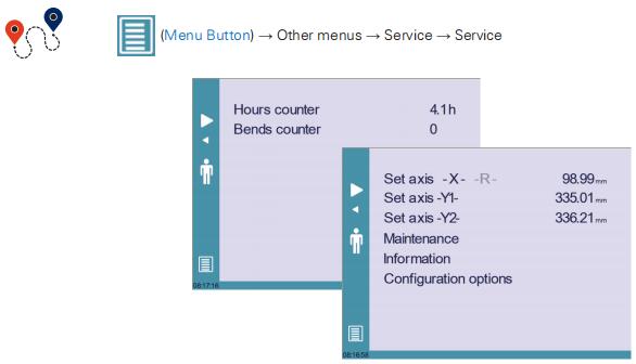
Set Axis
Allows the operator to manually adjust the position of the back gauge (axes X and R) and the beam (axes Y1 and Y2).
This function must be used with utter care and only by experienced personnel. Wrong settings may mechanically damage the machine. Settings are lost after indexing the machine.
Maintenance
The Maintenance page displays the hardware status of the CybTouch and lets the operator perform different maintenance actions.
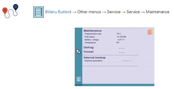
All the following actions require codes and should only be performed by technicians or upon request of a technician.
Defrag
This function will rearrange the memory space of the CybTouch. Simply touch it and follow the instructions given in the yellow pop-up window.
Format
This function will erase all data in the CybTouch. Only use this with the help of a technician.
Internal backup
This function is specially designed for OEM and support.
Usually a machine parameters’ backup is made by the machine manufacturer or the company who services the machine. This backup allows a maintenance technician to restore original working parameters if necessary.
Should there be a need to restore parameters, call on a maintenance technician and follow his instructions.
Do not try to use this function unless you are in dire need.
Before using this last function, make sure that all your files have been transfered outside the CybTouch (see USB Transfer, page 16).
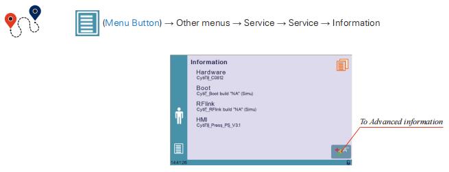
Information
The Information page displays the names and versions of the softwares installed on the CybTouch. Pressing the Advanced button shows more detailed information.
Configuration options
Touching this menu opens the following page, where one can find the computer’s identification and manage the machine’s options.
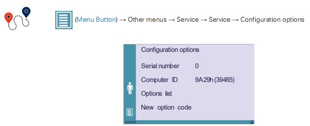
Serial number
This is the serial number of the CybTouch. It is entered at the factory at the end of the machine’s initial setup and is related to the machine’s option list.
Changing the serial number means that all the options installed on the machine can be lost.
Computer ID
This line displays an identification code that is unique to each CybTouch and guarantees, together with the serial number, a correct identification of the machine.
Option list
This function opens a yellow pop-up window where all the options installed on the CybTouch are displayed.
New option code
The function opens an alphanumerical pad where the code of the new option must be entered. The format of an option code is: ABC-DEF-GHI-JKLM
USB Transfer
![]()
Precautions
For a smooth transfer, please take the following precautions into consideration:
• The USB port of the CybTouch is meant to be used only with a storage media of the «Memory stick» type.
• The port is a standard USB 2.0 port, USB 1.1 compatible.
• USB 3.0 key that are USB 2.0 compatible, should normally work. There’s however no guarantee, as it depends of the firmware of these new keys.
• CD and external HDD are not accepted.
• Although unlikely, it is possible to find a USB key that is not compatible with the CybTouch. If so, try with another one.
3 rules for a fast and easy transfer:
 Use a USB key dedicated to files transfer with the CybTouch.
 Less files means a faster transfer.
 The file’s path on the key is limited to 255 characters.
Importing parts from other Cybelec NCs
CybTouch 12 is delivered with Cybelec’s off-line software PC-ModEva, which controls most of the other numerical controls produced by Cybelec.
From version Tx, PC-ModEva includes CybTouchConverter (see page 39), which allows you to convert parts to the CybTouch format, and import them into your machine with the above mentioned function.
Part 3 — Basic Page Description
Bend Numerical Page
Available functions on the Bend Num page
The Bend Numerical Page is normally the working page, from which the bends are executed, and most of the navigation originates from and leads to.

Current step (sequence) number
Touching the step number will open a yellow pop-up window as shown here, with 3 different actions to choose from:
• Insert step: this function will insert a step after the current one.
• Delete step: this function will erase the current step.
• Go to step: this function allows jumping directly to the desired step.
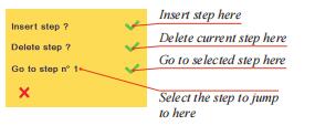
The Insert step and Delete step functions cannot be used on parts created with the TouchProfile Mode (see page 30).
Set-point beam (Y axis) / bend angle
The CybTouch has three different modes to manage the Y axis. Touching one of the icons on the left allows going from one mode to another. The three modes are:
![]() • : in this mode, the operator simply enters the desired angle and the CybTouch will calculate the position at which the beam will stop (BDC).
• : in this mode, the operator simply enters the desired angle and the CybTouch will calculate the position at which the beam will stop (BDC).
![]() • : in this mode, the operator can see the calculated target of the angle. It is possible to change the value.
• : in this mode, the operator can see the calculated target of the angle. It is possible to change the value.
![]() • : this is the bottoming mode. When the beam stops, or when the target value is reached, the bending cycle continues (dwell time, return).
• : this is the bottoming mode. When the beam stops, or when the target value is reached, the bending cycle continues (dwell time, return).
When activated, the calculated bottoming value is displayed in gray. It is however possible to modify this value, which will then be displayed in black. It can only be used if both the tools accept bottoming(see Punches, page 24 and Dies, page 26).
Set-point back gauge (X axis) / flange length
The CybTouch has two different modes to manage the back gauge X axis. Touching one of the icons on the left allows going from one mode to another. The two modes are:
![]() • : in this mode, the operator simply enters the desired length for the flange and the CybTouch will calculate the position for the back gauge X axis. This mode is only available when programming a part with the Numerical Mode(see page 33).
• : in this mode, the operator simply enters the desired length for the flange and the CybTouch will calculate the position for the back gauge X axis. This mode is only available when programming a part with the Numerical Mode(see page 33).
![]() • : this mode shows the targeted position for the back gauge X axis.
• : this mode shows the targeted position for the back gauge X axis.
User Preference Show L first (see page 11) allows choosing which mode is displayed by default first.
More Page
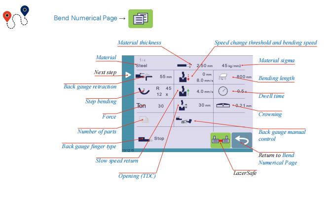
Available functions on the More page
The More page displays parameters related to the part, and depending on the CybTouch configuration and the type of action performed, it also displays various settings for the current bend.

Material
This is not a sequence parameter, but of course a part parameter. Each touch on the material’s name selects the next available from the list of Materials (see page 9).
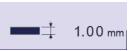
Material thickness
The default thickness, defined in Materials (see page 9), is automatically displayed when changing material. It is however possible to change it simply by touching this icon.
If on the other hand, the parameter Predefined thickn. (see page 9) is set to yes, a touch on this icon will open a numerical pad as show to the right, where the operator will be able to select directly
one of the predefined thicknesses.
This is a part parameter.
![]()
Material sigma
The default sigma, defined in Materials (see page 9), is automatically displayed when changing material. It is however possible to change it simply by touching this icon. This is also of course a part parameter.
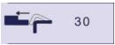
Back gauge retraction
The back gauge retraction can be activated/deactivated at its Default retraction (see
page 10) value using this icon. It is possible to modify the value by touching it. This is a
sequence parameter, meaning it can be modified with each step of the program.
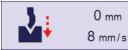
Speed change threshold and bending speed
The distance parameter allows the operator to increase the height of the speed change point. The speed parameter allows decreasing the bending speed from its maximum value defined in the machine parameters.
![]()
Bending length
This parameter defines the width of the sheet metal part that will be pinched between the
tools. It is used to calculate the bending force.
If this parameter is not activated (gray), the CybTouch will not calculate the bending Force and the Crowning.
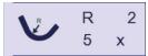
Step bending
When a large radius bend has been programmed (see L-Alpha Mode, page 34), its parameters are displayed here. It is possible to modify them directly here.
Programming 99 x will automatically calculate the maximum possible step bends. The resulting value may be reduced. However, if it is increased over the maximum calculated value, the resulting radius and angle will be drastically affected.
The large radius bending function is deactivated when this field is grayed.
Slow speed return
This parameter allows slowing down the speed of the beam after the bend, and is generally used when the part has a long flange and the operator tries not to let it “fall
down too fast”.
The beam will return at low speed up while the operator holds the foot pedal. It switches to high speed up when either the pedal is released or Pinch Point is reached, whichever comes first.
When this field is deactivated (grayed), the beam moves back up directly at HSU (High Speed Up).

Dwell time
Allows defining the duration of the dwell time, meaning the time during which the punch
remains at BDC before coming back up.
When this field is deactivated (grayed), the default Dwell Time value defined in the machine parameters is applied.
Force
The force is automatically calculated by the CybTouch, according to the Material, the Material thickness, the Material sigma and the Bending length. The value can also be manually modified here.
Opening (TDC)
For parts created with a profile (see TouchProfile Mode (optional) or L-Alpha Mode), this value is automatically calculated to allow the operator enough room to extract its bent part
from between the tools. It is however possible to change it manually.
For part created manually (see Numerical Mode), this parameter uses the default minimum value defined in the machine parameters. It can however be programmed here.
Creating a “New part” reinitializes it to its default value.
Crowning
The crowning function is activated here. It is automatically calculated, according to the Material, the Material thickness, the Material sigma and the Bending length. If the
crowning needs correction, use the Crowning (see page 36) function in the correction page.
The value can be manually changed by operator. It will however be automatically recalculated if any of the values used for its calculation is changed.
When the crowning function is deactivated (gray icon), the crowning system physically remains to its last position and does not automatically return to 0.0 mm. Keep that in mind when using this function – or not – between one sequence and the following.
![]()
Back gauge finger type
The back gauge dimensions are defined in the machine parameters. This function allows browsing through the available support and stop positions of the back gauge. This function may be available, or not, according to the machine configuration.
Number of parts
The operator can enter here the total amount of parts to be produced. Every time all the sequences of the program are executed, hence a part is completed, this counter is updated of one unit (increased or decreased, see Program counter mode, page 11). When the amount of parts is reached, a yellow pop-up window signals it to the operator。
Back gauge manual control
Activating this parameter gives manual control over the back gauge movement. This means the operator must personally give the start to the back gauge movement, using for example the foot switch or the start button.
![]()
Offset Pinch Point
This function allows making a bending cycle further away from the matrix, for example to close the opened side of a box, as shown on the right.
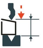
Once activated, this function forces the CybTouch into bottoming mode (see Set-point beam (Y axis) / bend angle, page 18).
With this function, the Speed Change Point occurs higher, and the operator can inch the beam down with short impulses on the pedal, until the proper height is reached. The parameters Speed change threshold and bending speed (see page 20) can also be useful in this situation.
Proceeding this way is normally used for unit or small series. If however the number of parts is large, the operator can enter a target value in the bottoming field, which will then turn black. This way, the CybTouch will execute a normal bending cycle, stopping the beam at the programmed value, i.e. saving a lot of production time.
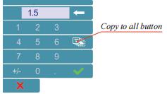
This function allows copying a defined value to all the steps of the current program. It appears in the numerical pad of relevant fields, such as Bending length, Force, Bending and Corrections, etc.
Part4 — Tools Management
Tools management allows the creation and configuration on the CybTouch of the tools to be used on the machine. These tools are then taken into account in bend calculations.
Once a punch and die are created and selected, you can select the bend angle you require as well as the flange length (L). The CybTouch then calculates the positions for axes X and Y for the bend.
Punches
Setting Instructions:
To select a punch, simply browse through the existing punches in your library using the
arrows buttons, and then return to Bend Numerical Page.
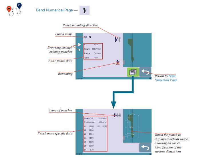
How to create or modify a punch?
If no punch is yet created, the punch will have no name (??? is displayed). If a punch already exists, then the last punch used will be selected, here 60_N (modifications will not alter the existing punch as they will be saved under another name).
1. Touch the punch icon ![]() to access the punch details.
to access the punch details.
2. Enter the basic characteristics (α (punch angle), Height, Radius and Ton/m) for the new punch to be created.
3. Touch the ![]() button to invert the punch if necessary.
button to invert the punch if necessary.
4. Select the ![]() or
or![]() icon to define the tool as resistant for bottoming.
icon to define the tool as resistant for bottoming.
5. Touch the ![]() button to display the More page.
button to display the More page.
6. Select the punch type (straight, normal or gooseneck) with this icon![]() .
.
7. Enter the more specific dimensions L1 to Lx by referring to the graphic representation on the right of the screen. Touching this image will display the default representation of the tool, making it easier to identify the various dimensions.
Note: The dimensions L1 to Lx are the same as the ones used in PC 1200, DNC 880S, ModEva’s. If you use the same tools, print them from PC1200 to easily program them in the CybTouch. Of course consider giving the same tools the same name.
8. Enter the following values:
• Safety XS: Security distance between the tool and the back gauge for X axis.
• X correction: If the punch is not perfectly aligned.
9. Return to previous page![]() .
.
To be allowed to save a tool, a level 2 password is required.
10. Touch the punch name (here 60_N).
11. Touch Save punch to overwrite the existing tool or Save punch as if you want to save your tool under another name.
12. Enter the name of the new punch using the alphanumerical keypad.
Note: We recommend that you follow the naming conventions explained in Naming Tools (see page 28).
13. Touching the![]() button brings you back to the program page, with the punch you just saved being selected and ready to be used.
button brings you back to the program page, with the punch you just saved being selected and ready to be used.
Dies
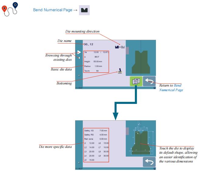
Setting Instructions
Selecting a die is the same as selecting a punch; simply browse through the existing dies in your library using the arrows buttons, and then return to Bend Numerical Page.
How to create or modify a die?
If no die is yet created, the die will have no name (??? is displayed). If a die already exists, then the last one used will be selected, here 30_12 (modifications will not alter the existing die as they will be saved under another name).
1. Touch the die icon![]() to access the die details.
to access the die details.
2. Enter the basic characteristics (Ve (die width), α, Height, Radius and Ton/m) for the new die to be created.
3. Touch the![]() button to invert the die if necessary.
button to invert the die if necessary.
4. Select the![]() or
or ![]() icon to define the tool as resistant for bottoming.
icon to define the tool as resistant for bottoming.
5. Touch the![]() button to display the More page.
button to display the More page.
6. Enter the more specific dimensions L1 to Lx by referring to the graphic representation on the right of the screen. Touching this image will display the default representation of the tool, making it easier to identify the various dimensions.
Note: The dimensions L1 to Lx are the same as the ones used in PC 1200, DNC 880S, ModEva’s. If you use the same tools, print them from PC1200 to easily program them in the CybTouch. Of course consider giving the same tools the same name.
7. Enter the following values:
• Safety XS: Security distance between the tool and the back gauge for X axis.
• Safety RS: Security distance between the tool and the back gauge for R axis.
• Retr. zone: Retraction zone.
8. Return to previous page ![]() .
.
To be allowed to save a tool, a level 2 password is required.
9. Touch the die name (here 30_12).
10. Touch Save die to overwrite the existing tool or Save die as if you want to save your tool under another name.
11. Enter the name of the new die using the alphanumerical keypad.
We recommend that you follow the naming conventions explained in Naming Tools (see page 28).
12. Touching the ![]() button brings you back to the program page, with the die you just saved being selected and ready to be used.
button brings you back to the program page, with the die you just saved being selected and ready to be used.
Naming Tools
It is recommended that you use naming conventions for your tools. Below you will find a simple convention allowing you to precisely identify a punch or die through its name.
Of course, depending on your needs you may need to create more rules for punch and die naming.
Punches Dies
The name of the punch should be built in the following manner: first its angle, followed by its type, and then whether it is inverted or not.
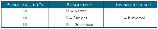
Following these rules, here are some examples of punch names: 90_N_i, 60_G, 30_S, and so on, and so forth.
Dies
The name of the punch should be built in the following manner: first its angle, followed by its type, and then whether it is inverted or not.
The name of the die should be built in pretty much the same manner: first its width (Ve dimension), followed by its angle, and then whether it is inverted or not.
Following these rules, here are some examples of die names: 12_86_i, 16_86, 20_30, and so on, and so forth.
Back Gauges
If the operator needs to intervene on the machine’s back gauges, he can use the back gauge cycle function, which will bring them all the way forward. He will then be able to work on them without having to put his hands and arms between the tools.
This function may not be available, depending on the machine’s configuration. The function’s icon is only visible when the machine is indexed.
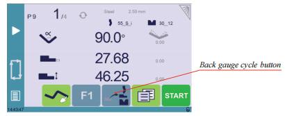
Setting Instructions:
1. Make sure the machine is indexed. This button ![]() is not available when it is not the case.
is not available when it is not the case.
2. Press the back gauge cycle button![]() for more than 2 seconds to initiate the cycle.
for more than 2 seconds to initiate the cycle.
3. The back gauges position themselves all the way forward, between the tools. If the beam is not at TDC, it will move first all the way up before the back gauges begin to move.
4. Once the intervention is done, touch the cycle button![]() again to deactivate the function, and press the button
again to deactivate the function, and press the button![]() .
.
Part 5 — Creating a Part Program
There are three ways to create a program part: with the TouchProfile Mode (optional), with the Numerical Mode (see page 33), and with the L-Alpha Mode (see page 34).
In this chapter the machine is considered operational: machine parameters, tools (see Tools Management, page 24), materials (see Materials, page 9), etc. are already configured and programmed.
TouchProfile Mode
In this mode, the operator can very intuitively draw a profile directly on the screen.
Setting Instructions:
1. Touch the program number and select New program in the list.
2. First select the material, the Material thickness (see page 19) and the tools to be used for the part by touching their respective icons.
3. Draw the profile by touching the screen where you want to add a segment.
4. Touch on the middle of a segment to modify its value.
Touching this icon ![]() allows erasing the last segment added.
allows erasing the last segment added.
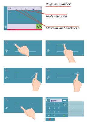
5. Touch on an angle to modify its value.
Touching the icon![]() will open a yellow pop-up, in which it possible to:
will open a yellow pop-up, in which it possible to:
• Activate (and deactivate) a special tool by touching its icon, and select it from a list by pressing ???. • Change the value of the radius (see also Step bending, page 20) and define how many steps the NC will make to execute it.
6. Should it prove difficult to select a particular segment or angle, it is possible to zoom on an area by touching this button![]() and then on the desired zone.
and then on the desired zone.
One can also choose to enter the length and angle values in the L-Alpha Mode page by pressing this![]() button.
button.
7. Once all the segments and angles are adjusted, press this button![]() to access the Manual Bend Sequencing (see page 31).
to access the Manual Bend Sequencing (see page 31).
Manual Bend Sequencing (Optional)

Once the shape of the part has been defined, the bending sequence for the part can be automatically determined by the CybTouch.
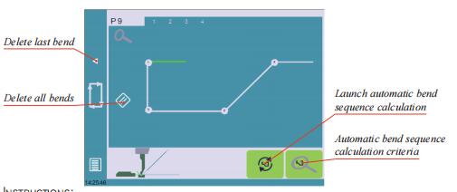
Setting Instructions:
1. Simply touch the bend sequence calculation button ![]() . Once the sequence is calculated, the Bend 2D screen is displayed.
. Once the sequence is calculated, the Bend 2D screen is displayed.
2. If the option is not installed, simply touch the bend in the order that you want them performed. A small number is displayed on the bend, indicating its position in the sequence.
Pressing the back button will erase the last bend in the sequence. If you wish to delete all bends, simply touch the button.
3. Immediately after determining the last bend to be selected, the Bend 2D screen here below is displayed.
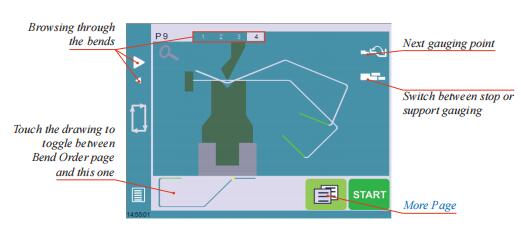
4. In the Bend 2D page, the operator must determine the back gauge and part position for each bend, and if necessary the special parameters on the More Page (see page 19).
5. Press ![]() and select Bend num page to return to the Bend Numerical Page.
and select Bend num page to return to the Bend Numerical Page.
6. Start the hydraulic pump motor (by pressing this button ![]() if available. It turns red
if available. It turns red
when the motor is running).
7. Press the ![]() button to position the machine according to the data that were just entered.
button to position the machine according to the data that were just entered.
8. When the machine is ready to bend, a ![]() button is displayed.
button is displayed.
9. If you want to repeat the same step in order to apply all the necessary corrections to it, switch to the Semi-Automatic mode (see page 35).
10. Press the foot switch to execute the bend.
Numerical Mode
It is also possible to simply create a part program directly on the Bend Numerical Page.
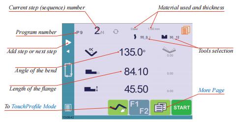
Setting Instructions:
1. Touch the program number and select New program in the list.
2. First select the tools to be used for the part by touching their respective icons (see Tools Management, page 24).
3. Touch the material’s name (here Steel). The More Page (see page 19) is displayed.
4. In the More Page, select the Material used, enter the Material thickness, the Bending length, and other sequence parameters (Opening (TDC), Slow speed return, etc.).
5. Touch the![]() button to return to the Bend Numerical page.
button to return to the Bend Numerical page.
6. Touch the numerical value next to the angle icon![]() , and enter the value for the first bend you wish to create (here 90°).
, and enter the value for the first bend you wish to create (here 90°).
7. Touch the numerical value next to the segment length icon![]() , and enter the value for the first segment you wish to create (here 30.00 mm).
, and enter the value for the first segment you wish to create (here 30.00 mm).
8. Add the next bend to the program by touching![]() .
.
9. Proceed in the same manner to create the other segments of the part.
10. Touch ![]() to return to the first bend.
to return to the first bend.
11. Start the hydraulic pump motor (by pressing this button![]() if available. It turns red when the motor is running).
if available. It turns red when the motor is running).
12. Press the![]() button to position the machine according to the data that were just entered.
button to position the machine according to the data that were just entered.
13. When the machine is ready to bend, a ![]() button is displayed.
button is displayed.
14. If you want to repeat the same step in order to apply all the necessary corrections to it, switch to the Semi-Automatic mode (see page 35).
15. Press the foot switch to execute the bend.
L-Alpha Mode
This page is only available if user preference Show page L-alpha num (see page  is set to yes.
In this mode, the operator can define each step (length or angle) of a profile on a table.
Setting Instructions:
1. Touch the program number, select New program in the list and press this button![]() to access the L-alpha mode.
to access the L-alpha mode.
2. First select the material, its thickness and the tools to be used for the part by touching their respective icons.
3. Touch the first value in the table (here 200.00). The window to the right is displayed.
4. Enter the value for the first segment’s length and touch the![]() button to add another step.
button to add another step.
Click on OK when prompted to create new step.
5. Proceed in the same manner for all steps and angles of the profile.
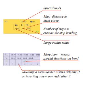
6. If a bend needs special parameters (large radius, special tool), press in the more field of the corresponding sequence.
A special punch or /and die means there must be an additional working station.
7. A yellow pop-up is displayed, in which it possible to:
• Activate (and deactivate) a special tool by touching its icon, and select it from a list by pressing ???. • Change the value of the radius (see also Step bending, page 20) and define how many steps the NC will make to execute it.
8. A small More icon shows that something special is programmed on the bend.
9. To remove the icon (and special parameters), return to the yellow popup, touch all the activated functions to make them turn gray, and select OK.
10. Once all the segments and angles are adjusted, press this button![]() to access the Manual Bend Sequencing (see page 31).
to access the Manual Bend Sequencing (see page 31).
Bending and Corrections
All program corrections are made in the Bend Numerical Page (see page 17). According to his preferences, the operator can choose to execute all the steps of the program
one after the other, making corrections along the way. Or he can choose to apply all the corrections necessary to the same step before moving to the next one using the SemiAutomatic mode.
Corrections can be made to:
• The angle (Y1 + Y2, see Angle Correction (Y axis), page 36 and/or crowning if available, see Crowning, page 36),
• The back gauge position (X and R, if available), see Back gauge (X & R axes) Correction, page 37.
Semi-Automatic mode
The semi-automatic mode allows repeating the same sequence indefinitely. It is used when the operator wants to apply corrections to his part one bend after another. He can
thus execute the same step until he gets the desired result, before moving to the next one by means of the![]() button.
button.
The semi-automatic mode is activated (and deactivated) by touching for more than one second on the ![]() button.
button.
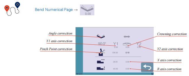
Angle Correction (Y axis)
After physically measuring the angle, if corrections are to be made, they must be done on this page, and not directly in the program step.
Setting Instructions:
1. Touch the angle correction ![]() icon, and enter the physically measured value of the angle. The numerical control will automatically calculate the Y1 and Y2 axes corrections.
icon, and enter the physically measured value of the angle. The numerical control will automatically calculate the Y1 and Y2 axes corrections.
Pressing this ![]() button will reset all angle corrections.
button will reset all angle corrections.
2. Depending on the position of the sheet metal in the press, it may be necessary to fine-tune the beam’s corrections. It is possible by simply touching this icon ![]() or this
or this ![]() one, and entering the desired values.
one, and entering the desired values.
Crowning
3. Corrections to the crowning value can be made by touching this icon ![]() .
.
4. The numerical control automatically calculates the Pinch Point height. If it needs correction, it can be done by touching this icon![]() .
.
The grayed value next to the Pinch Point correction icon is the value calculated by the numerical control, and thus the value onto which the correction will be applied.
Back gauge (X & R axes) Correction
5. Touching this icon![]() allows applying a correction to the back gauge X axis position.
allows applying a correction to the back gauge X axis position.
6. Touching this icon![]() allows applying a correction to the back gauge R axis position.
allows applying a correction to the back gauge R axis position.
The grayed values next to the back gauge correction icons are the value calculated by the numerical control, and thus the values onto which the corrections will be applied. The back gauge positions corrections can also directly be made on the Bend Numerical Page (see page 17).
Next-Part Function
This function allows the operator to run two, or several, part-programs one after another.
This is very handy when one wants to make a three dimensional part, like a box for example, or make a final product composed of several parts.
The CybTouch will execute the current program. At the end of the last sequence, instead of returning to the first sequence of the current program, the CybTouch switches to the program selected as P+nn (i.e. the next one). It goes on like this, as long as a part is programmed with a next one.
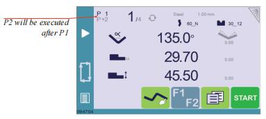
Setting Instructions:
1. To activate the Next-Part function, touch the Program number (e.g. P1) and keep it pressed until the following numerical pad is displayed.
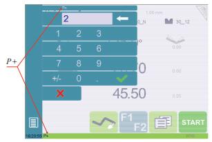
2. Enter the number of the program that must be executed at the end of the current one.
3. Save the program (see Saving a Program, page 41).
Cycles and quantities
It is naturally possible to cycle the programs, meaning that the program following the last one is the first one. There are however some specificities to take into consideration when one wants to produce certain amount of cycled programs.
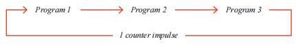
In the diagram above, an assembly needs 3 programs to be completed: program 1 is followed by program 2, which in turn is followed by program 3. To complete the cycle, program 3 is programmed to be followed by program 1. In such a case, the value of the part counter will be updated (see Number of parts, page 22) of 1 unit when it goes from program 3 to program 1.
The CybTouch is designed like this: every time the program following the current one has a smaller number, the counter value is changed.
When a series of programs corresponds to one single part, make sure that their intrinsic numbers increase chronologically.
CybTouchConverter
CybTouchConverterCybTouchConverter is a tool allowing the conversion of products/parts files from PC-ModEva (formerly PC1200) to CybTouch. Owners of Cybelec’s ModEva type machines
can thus produce the same parts on a ModEva or a CybTouch.
How to Convert a Part-Program?
1. Check that the version of PC-ModEva installed on your PC is recent enough to contain CybTouchConverter.
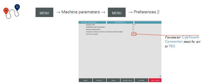
2. Activate the CybTouch Converter function in the machine parameter
3. In the List of Products’ page, start the CybTouch Converter

4. Select the destination folder for the converted files.
5. Select the part(s) that you want to convert and touch this![]() button.
button.
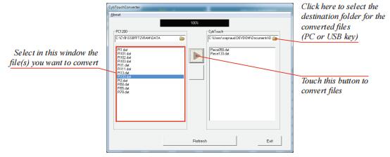
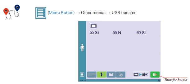
6. The program-parts are now converted and located on your PC or USB key. They can be directly transfered on the CybTouch, using the USB Transfer (see page 16).
Part 6 — Saving and Loading a Program
Saving a Program
After creating a program, an operator can save the program in order to use it again:
1. Touch the Program number (e.g. P0).
2. Touch Save program.
3. Enter the number you wish to give to the program (e.g. 1 for P1), followed by ![]() .
.
4. The program is now called P1 and is saved in the CybTouch
Loading a Program
To call (load) a program:
1. Touch the Program number (e.g. P1).
2. Touch Call program.
3. Select the program to be loaded from the list (e.g. 002 for P2).
4. The selected program (P2) is then loaded into the work memory and is ready to be used.
Deleting a Program
To delete a program:
1. Touch the Program number (e.g. P1).
2. Touch Delete program.
3. Select from the list the program to be deleted.
4. Touch ![]() to confirm.
to confirm.
Part 7 — EasyBend Page
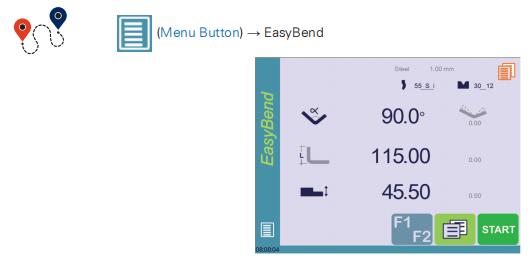
The EasyBend page is used for individual bends, for example when an external worker needs to interrupt production just to make a single bend (usually with the same tools).
The program currently being used for production is only temporarily interrupted (no need to save it) when switching to the EasyBend page, and then resumed again when returning to the program page (Menu Button → Current program).
Making a bend on the EasyBend Page
See Basic Page Description, page 17 for more information on the different controls on the EasyBend page.
Setting Instructions:
1. Touch the material’s name (here Steel). The More Page (see page 19) is displayed.
Select the Material (see page 19) used, enter the Material thickness and the Bending length.
2. Touch one of the tool’s icon ( ![]() or
or![]() ) to select a punch or die. To learn how to configure tools, please refer to section Tools Management, page 24.
) to select a punch or die. To learn how to configure tools, please refer to section Tools Management, page 24.
3. Enter the angle![]() for the bend you wish to create (here 90°).
for the bend you wish to create (here 90°).
4. Enter the flange’s length![]() (here 100.00 mm).
(here 100.00 mm).
5. Enter the back gauge height value![]() (here 0 mm)
(here 0 mm)
6. Press this button![]() to go to the More Page (see page 19) and enter the eventually required extra data for the bend.
to go to the More Page (see page 19) and enter the eventually required extra data for the bend.
7. Start the hydraulic pump motor (by pressing this button ![]() if available. It turns red when the motor is running).
if available. It turns red when the motor is running).
8. Press the ![]() button to position the machine according to the data that were just entered.
button to position the machine according to the data that were just entered.
9. When the machine is ready to bend, a ![]() button is displayed.
button is displayed.
10. Press the foot switch to execute the bend.
Part 8 — Error and Warning Messages
Following is a list of warning and error messages which may be displayed on the interactive message line of the CybTouch.
There are two types of messages:
• Warning Messages, which are displayed on a green background. They are information or instructions that will disappear automatically.
• Error Messages (machine or NC errors), which are displayed on a red background. They inform the user of an error occurring on the machine or NC, and sometimes require intervention by
the end user or a technician.
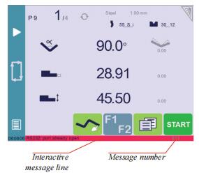
When reporting error messages, please ALWAYS indicate the error number at the end of the line. This number also refers to the first column in the section below.
Warning Messages
Beam Error Messages

This table does not contain an exhaustive list of all the errors related to beam. If the message number is not explained here, please write it down and contact your dealer.
Internal Reset Error Messages
This kind of messages appears if a serious error occurred. The display automatically switches to a page as shown below.
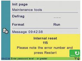
If such an error occurs,
• Write down the error number and press the Restart button.
• If the error remains, turn the machine off and let it cool down before restarting it.
• If the error still remains, write down the error number and contact your dealer.
—End
The Intuitive Programming
Opening (TDC) …………………………………………………………………………………………………………………………….17
Crowning ………………………………………………………………………………………………………………………………………17
Back gauge finger type …………………………………………………………………………………………………………………..17
Number of parts ……………………………………………………………………………………………………………………………17
Back gauge manual control ……………………………………………………………………………………………………………17
Tools Management …………………………………………………………………………………… 18
Punches ……………………………………………………………………………………………………………………… 18
How to create or modify a punch? ………………………………………………………………………………………..19
Dies ……………………………………………………………………………………………………………………………. 20
How to create or modify a die? …………………………………………………………………………………………….21
Naming Tools ……………………………………………………………………………………………………………… 22
Punches ……………………………………………………………………………………………………………………….22
Dies …………………………………………………………………………………………………………………………….22
Creating a Part Program ……………………………………………………………………………. 23
TouchProfile Mode …………………………………………………………………………………………………….. 23
Numerical Mode …………………………………………………………………………………………………………. 26
L-Alpha Mode …………………………………………………………………………………………………………….. 27
Bend Correction …………………………………………………………………………………………………………. 28
Angle Correction (Y axis) ………………………………………………………………………………………………….28
Crowning ……………………………………………………………………………………………………………………..29
Saving a Program ………………………………………………………………………………………………………… 30
Loading a Program……………………………………………………………………………………………………… 30
Deleting a Program …………………………………………………………………………………………………….. 30
EasyBend Page ………………………………………………………………………………………… 31
Добрый день!
Китайский пресс с Cybelec Cybtouch CT-12. Оси Y1,Y2, X, R +V
Все работает нормально, но есть мелкие вопросы по логике работы ЧПУ.
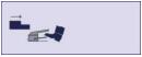
1. На одноручьевой матрице когда задний упор работает близко от нее он подходит к ней с подъемом по оси R чтобы избежать столкновения с матрицей, а потом уже опускается на нее. Но на других матрицах ЧПУ этого не делает, хотя их создавали редактируя профиль той в которой это движение есть. Вопрос : где задаются параметры этого «подскока» для разных профилей матрицы? Можно ли установить эту зону для разных матриц индивидуально?
2. Как ЧПУ рассчитывает коррекцию по Y при радиусной пошаговой гибке(step bending)? Это величина коррекции к единичному гибу или это произведение коррекции и числа гибов в цикле? К примеру -при коррекции по Х величина коррекции добавляется к каждому шагу в цикле, а не ко всем гибам вначале, поэтому сместить гиб на неск. миллиметров не получается без вмешательства в размер полок.
3. После установки на фундамент и работы разной интенсивности несколько лет, есть небольшая 0,01-0,05мм коррекция на одну ось, то есть по факту Y1 на пару соток выше чем Y2, как это установить цифровым способом через машинные параметры? Потому что ловить механически такие малые величины тягами линеек не очень удобно.
На первых фото профиль матрицы на которой «подскок» работает, на второй матрице под плющение нет.

на этой матрице «подскока» нет
Буду благодарен за помощь!