Contents
1. Introduction …………………………………………………………………………………………………………………………………….. 4
1-1 Product Overview ……………………………………………………………………………………………………………………… 4
1-2 Hardware Description ………………………………………………………………………………………………………………… 5
2. Getting Started ………………………………………………………………………………………………………………………………… 7
3. VoIP Gateway Web Configuration …………………………………………………………………………………………………… 13
3-1 Status…………………………………………………………………………………………………………………………………….. 13
3-1-1 Current Status ……………………………………………………………………………………………………………….. 13
3-1-2 RTP Packet Summary…………………………………………………………………………………………………….. 14
3-1-3 System Information ………………………………………………………………………………………………………… 15
3-1-4 Routing Table ………………………………………………………………………………………………………………… 16
3-1-5 LAN Client …………………………………………………………………………………………………………………….. 16
3-2 FXS Line Diagnostics ………………………………………………………………………………………………………………. 17
3-2-1 FXS Outward Test ………………………………………………………………………………………………………….. 17
3-2-2 FXS Inward Self Test………………………………………………………………………………………………………. 18
3-3 General Settings ……………………………………………………………………………………………………………………… 19
3-3-1 WAN …………………………………………………………………………………………………………………………….. 19
3-3-2 LAN ……………………………………………………………………………………………………………………………… 23
3-3-3 SIP……………………………………………………………………………………………………………………………….. 24
3-3-4 SIP Advanced………………………………………………………………………………………………………………… 28
3-3-5 Caller ID ……………………………………………………………………………………………………………………….. 32
3-3-6 Hot Line ………………………………………………………………………………………………………………………… 33
3-3-7 Line settings ………………………………………………………………………………………………………………….. 34
3-3-8 FAX………………………………………………………………………………………………………………………………. 38
3-3-9 Calling Features …………………………………………………………………………………………………………….. 40
3-3-10 Phone Book…………………………………………………………………………………………………………………. 43
3-3-11 CDR Settings……………………………………………………………………………………………………………….. 44
3-4 Advanced Settings…………………………………………………………………………………………………………………… 45
3-4-1 Codec setting ………………………………………………………………………………………………………………… 45
3-4-2 Digit Map ………………………………………………………………………………………………………………………. 46
3-4-3 DTMF & PULSE …………………………………………………………………………………………………………….. 49
3-4-4 CPT / Cadence………………………………………………………………………………………………………………. 50
3-4-5 TR069…………………………………………………………………………………………………………………………… 52
3-4-6 Caller Filter……………………………………………………………………………………………………………………. 54
3-4-7 Static Route…………………………………………………………………………………………………………………… 55
3-4-8 QoS Settigs …………………………………………………………………………………………………………………… 56
3-4-9 DDNS …………………………………………………………………………………………………………………………… 57
3-4-10 NAT Traversal………………………………………………………………………………………………………………. 58
3-4-11 DoS Protection …………………………………………………………………………………………………………….. 59
3-5 SNMP ……………………………………………………………………………………………………………………………………. 66
3-6 Tools ……………………………………………………………………………………………………………………………………… 67
3-6-1 Ping Test……………………………………………………………………………………………………………………….. 67
3-6-2 STUN Inquiry…………………………………………………………………………………………………………………. 68
3-7 System Settings………………………………………………………………………………………………………………………. 69
3-7-1 NTP ……………………………………………………………………………………………………………………………… 69
3-7-2 Login Account………………………………………………………………………………………………………………… 70
3-7-3 Backup / Restore……………………………………………………………………………………………………………. 71
3-7-4 System Log …………………………………………………………………………………………………………………… 72
3-7-5 Save / Restart………………………………………………………………………………………………………………… 72
3-7-6 Software Upgrade ………………………………………………………………………………………………………….. 73
3-7-7 Logout ………………………………………………………………………………………………………………………….. 73
4. Configuring the VoIP Gateway through IVR …………………………………………………………………………………….. 74
4-1 IVR (Interactive Voice Response) ……………………………………………………………………………………………… 74
4-1-1 IVR Functions Table: ………………………………………………………………………………………………………. 75
4-2 IP Configuration Settings—Set the IP Configuration of the WAN Port…………………………………………….. 76
4-2-1 Character Conversion Table:……………………………………………………………………………………………. 77
5. Dialing Principles …………………………………………………………………………………………………………………………… 78
5-1 Dialing Options ……………………………………………………………………………………………………………………….. 78
5-2 Dialed Number Processing Flow ……………………………………………………………………………………………….. 78
Appendix…………………………………………………………………………………………………………………………………………… 80
Product Features ………………………………………………………………………………………………………………………….. 80
На чтение 6 мин. Просмотров 56 Опубликовано 15.12.2019
8 страниц подробных инструкций и пользовательских руководств по эксплуатации
Содержание
- Прежде, чем начать Должно быть, по крайней мере, сл.
- Обзор устройства, Передняя панель
- Задняя панель, Порты phone, Reset
- Сообщение отправлено!
Прежде, чем начать Должно быть, по крайней мере, сл.
Dvg-5008s, Прежде, чем начать
Прежде, чем начать
Должно быть, по крайней мере, следующее:
Должно быть, по крайней мере, следующее:
Подписка на пакет услуг мультисервисного провайдера
Подписка на пакет услуг мультисервисного провайдера
Это устройство может быть настроено с
помощью Internet Explorer или Netscape
Navigator, 6.x или выше, с поддержкой
Javascript
Компьютер с приводом CD-ROM и портом Ethernet, работающий под
Компьютер с приводом CD-ROM и портом Ethernet, работающий под
Широкополосный модем с поддержкой Ethernet
Широкополосный модем с поддержкой Ethernet
Проверьте содержимое комплекта поставки
Проверьте содержимое комплекта поставки
В комплект поставки входит следующее:
В комплект поставки входит следующее:
Если какой-либо из указанных предметов отсутствует, пожалуйста,
обратитесь к поставщику.
Если какой-либо из указанных предметов отсутствует, пожалуйста,
обратитесь к поставщику.
Ethernet-кабель 5 категории
Использование источника
питания с иными
характеристиками может
привести к выходу из строя
устройства и лишению
гарантии.
Адаптер питания
постоянного тока 12 В
©2005 D-Link Systems, Inc. Все права защищены. Торговые марки или зарегистрированные
торговые марки являются собственностью соответствующих владельцев. Программное
обеспечение и спецификации были изменены без предварительного уведомления.
Маршрутизатор VoIP с портами FXS DVG-5008S.

Обзор устройства, Передняя панель
Указывает, что устройство включено.
Индикатор Run будет мигать во время выполнения
самодиагностики/загрузки и загорится постоянным
зеленым светом, если самодиагностика и загрузка
завершились неудачно.
Индикатор Alarm загорится постоянным красным светом,
если самодиагностика или загрузка завершились
неудачно. Индикатор Alarm замигает красным, когда
система зарегистрируется у провайдера или
зарегистрируется неудачно.
Индикатор WAN 10 или 100 загорится при установке
соединения. Мигание индикатора указывает на активность.
Если индикатор 10 или 100 не светится при подключенном
кабеле, проверьте подключенные кабели и убедитесь, что
устройства включены.
При установке соединения индикатор 10 или 100 загорится
на соответствующем порту. Мигание индикатора указывает
на активность. Если индикатор 10 или 100 не светится при
подключенном кабеле, проверьте подключенные кабели и
убедитесь, что устройства включены.
Этот индикатор отображает состояние VoIP и подключения
на телефонном порту, который используется для
соединения с обычными телефонами. Если телефон,
подключенный к телефонному порту, подсоединен к линии
или используется, индикатор светится. Когда телефон
звонит, индикатор мигает.

Задняя панель, Порты phone, Reset
Адаптер питания подключается в этом месте, Dc 12v
Если вы впервые подключаете оборудование к компьютеру, то вам следует настроить подключение на самом компьютере на автоматическое получение IP-адреса. Как это сделать, вы можете ознакомиться в разделе Интернет.
Подключение к web-интерфейсу:
1. Запустите web-браузер.
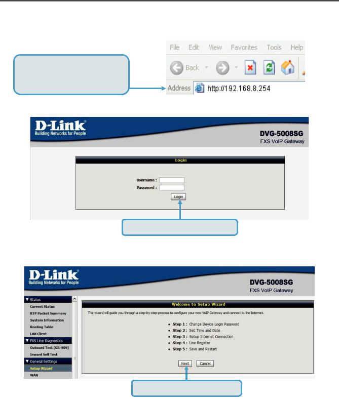
2. В адресной строке web-браузера введите IP-адрес маршрутизатора (по умолчанию – 192.168.8.254). Нажмите клавишу Enter.
3. На открывшейся странице введите имя пользователя и пароль администратора для доступа к web-интерфейсу маршрутизатора (по умолчанию имя пользователя – admin, пароль – пустой). Нажмите ссылку Login.

Если при попытке подключения к web-интерфейсу маршрутизатора браузер выдает ошибку типа «Невозможно отобразить страницу», убедитесь, что устройство правильно подключено к компьютеру.
Сразу после первого обращения к web-интерфейсу маршрутизатора откроется страница.

4. Переходим в раздел General Settings.
General Settings — WAN
В разделе WAN выбираем Static IP. Прописываем сетевые реквизиты, заполняя поля STATIC IP — IP address, Subnet mask, Default Gateway IP и DNS – Domain Name (Primary) IP, Domain Name (Sedondary) IP
В подразделе VoIP — Connection — WAN 1

После введения данных нажимаем кнопку ACCEPT
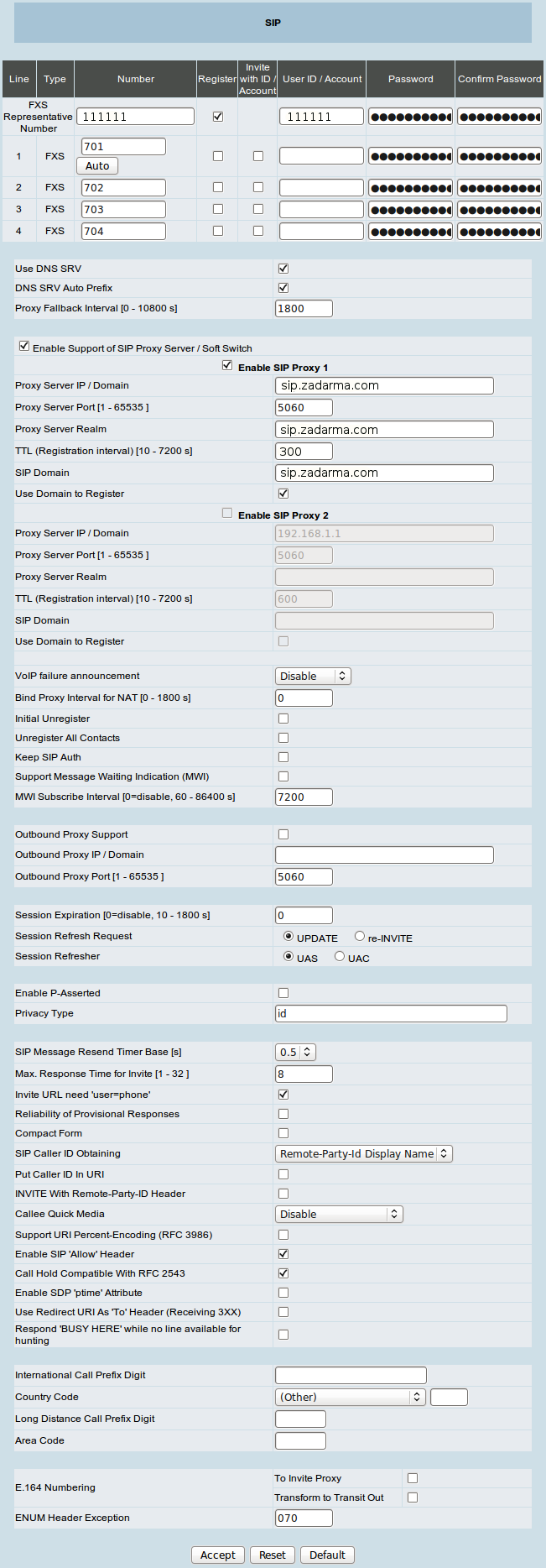
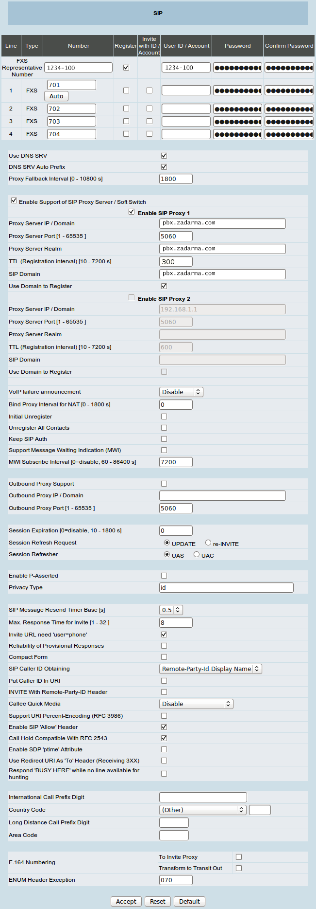
5. В разделе General Settings – SIP, прописываем номер абонента в формате e.164 и sip-server.
Включаем маркер напротив поля Enable Support of SIP Proxy Server / Soft Switch.
В поле FXS Representative Number прописываем номер в формате e.164

После введения данных нажимаем кнопку ACCEPT
6. General Settings – FAX
В разделе Fax / Modem на каждой линии выставляем T.38 Fax, а в поле FAX Max Rate: 9600

После введения данных нажимаем кнопку ACCEPT
7. Переходим в раздел Advanced Settings. В данном разделе настраиваем поля Codec Settings, Digit Map, DoS Protection Settings
g729 – Packet Interval (ms) – 20
g711a-law – Packet Interval (ms) – 30
g711u-law – Packet Interval (ms) – 30
Advanced Settings — Codec Settings

После введения данных нажимаем кнопку ACCEPT
8. Advanced Settings — Digit Map
Для пользователей г. Екатеринбург

Для пользователей г. Нижний Тагил

Для пользователей г. Первоуральск

Для пользователей г.Каменск-Уральский

После введения данных нажимаем кнопку ACCEPT
9. Advanced Settings — DoS Protection Settings
Снимаем маркер Enable DoS Protection

После введения данных нажимаем кнопку ACCEPT
10. В разделе System Settings сохраняем настройки Save/Restart, ставим маркер Save Settings и Restart и нажимаем кнопку ACCEPT
Сообщение отправлено!
В течение 1 часа мы свяжемся с вами для подтверждения заявки.
1. Настройка выполняется через веб-интерфейс. Для входа в веб-интерфейс введите IP-адрес шлюза в адресную строку браузера. Подключите компьютер к LAN порту шлюза, IP-адрес шлюза по умолчанию 192.168.8.254.
Также IP адрес шлюза можно узнать подключив к нему телефон и набрав **#101
Логин и пароль по умолчанию отсутствуют
Откройте раздел «General Settings» вкладку «SIP» и укажите следующие данные:
FXS Representative Number: Ваш sip-номер (Например 111111) из личного кабинета
FXS Representative Number: Ваш внутренний номер АТС (Например 1234-100) из личного кабинета
Register: ставим галочку
User ID / Account: Ваш sip-номер (Например 111111) из личного кабинета
Password: Ваш пароль от sip-номера, из раздела «Настройки-Подключение по SIP» личного кабинета.
Confirm Password: Ваш пароль от sip-номера, из раздела «Настройки-Подключение по SIP» личного кабинета.
Proxy Server IP / Domain: sip.zadarma.com
Proxy Server Realm: sip.zadarma.com
User ID / Account: Ваш внутренний номер АТС (Например 1234-100) из личного кабинета
Password: Ваш пароль внутреннего номера АТС личного кабинета
Confirm Password: Ваш пароль внутреннего номера АТС личного кабинета
Proxy Server IP / Domain: pbx.zadarma.com
Proxy Server Realm: pbx.zadarma.com
TTL (Registration interval): 300
SIP Domain: sip.zadarma.com
SIP Domain: pbx.zadarma.com
Use Domain to Register: ставим галочку
2. После внесения изменений нажмите кнопку «Accept» далее откройте вкладку
System Settings — System Operation установите отметки напротив следующих параметров
Save Settings и Restart после чего нажмите кнопку «Accept»
 03:21
03:21
Настройка VLAN Voip на роутере D’Link DVG N5402GF и настройка SIP регистрации
 04:42
04:42
Настройка SIP адаптера- D-link DVG-2102s
 02:33
02:33
SipParrot: Настройка VOIP-шлюза D-link DVG-7111s
 19:20
19:20
GATEWAY FXO DLINK 6004S
 05:13
05:13
D-Link DVG-N5402GF в режиме мост или обычный конвертер оптики в витую пару
 07:43
07:43
Gateway dvg6004s FXO conectando no elastix
 11:22
11:22
Configuração e Instalação Ata Dlink DVG-5112S
Прежде, чем начать
Должно быть, по крайней мере, следующее:
Должно быть, по крайней мере, следующее:
Подписка на пакет услуг мультисервисного провайдера
Подписка на пакет услуг мультисервисного провайдера
Это устройство может быть настроено с
помощью Internet Explorer или Netscape
Navigator, 6.x или выше, с поддержкой
Javascript
DVG-5008S
VoIP-шлюз
Компьютер с приводом CD-ROM и портом Ethernet, работающий под
управлением Windows
Компьютер с приводом CD-ROM и портом Ethernet, работающий под
управлением Windows
Широкополосный модем с поддержкой Ethernet
Широкополосный модем с поддержкой Ethernet
Проверьте содержимое комплекта поставки
Проверьте содержимое комплекта поставки
В комплект поставки входит следующее:
В комплект поставки входит следующее:
Если какой-либо из указанных предметов отсутствует, пожалуйста,
обратитесь к поставщику.
Если какой-либо из указанных предметов отсутствует, пожалуйста,
обратитесь к поставщику.
DVG-5008S — VoIP-шлюз
Телефонный кабель
Ethernet-кабель 5 категории
Компакт-диск
Использование источника
питания с иными
характеристиками может
привести к выходу из строя
устройства и лишению
гарантии.
Адаптер питания
постоянного тока 12 В
©2005 D-Link Systems, Inc. Все права защищены. Торговые марки или зарегистрированные
торговые марки являются собственностью соответствующих владельцев. Программное
обеспечение и спецификации были изменены без предварительного уведомления.
Маршрутизатор VoIP с портами FXS DVG-5008S.

2
Передняя панель
Индикатор
Power
Указывает, что устройство включено.
Run
Индикатор Run будет мигать во время выполнения
самодиагностики/загрузки и загорится постоянным
зеленым светом, если самодиагностика и загрузка
завершились неудачно.
Alarm
Индикатор Alarm загорится постоянным красным светом,
если самодиагностика или загрузка завершились
неудачно. Индикатор Alarm замигает красным, когда
система зарегистрируется у провайдера или
зарегистрируется неудачно.
WAN LED
Индикатор WAN 10 или 100 загорится при установке
соединения. Мигание индикатора указывает на активность.
Если индикатор 10 или 100 не светится при подключенном
кабеле, проверьте подключенные кабели и убедитесь, что
устройства включены.
Индикаторы
LAN
При установке соединения индикатор 10 или 100 загорится
на соответствующем порту. Мигание индикатора указывает
на активность. Если индикатор 10 или 100 не светится при
подключенном кабеле, проверьте подключенные кабели и
убедитесь, что устройства включены.
Индикаторы
Phone
Этот индикатор отображает состояние VoIP и подключения
на телефонном порту, который используется для
соединения с обычными телефонами. Если телефон,
подключенный к телефонному порту, подсоединен к линии
или используется, индикатор светится. Когда телефон
звонит, индикатор мигает.
Обзор устройства

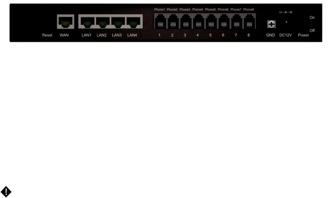
Задняя панель, Порты phone, Reset
Адаптер питания подключается в этом месте, Dc 12v
- Изображение
- Текст
Задняя панель
Порты
Phone
Для подключения телефонов, используя
стандартный телефонный кабель.
Для подключения компьютеров с портами Ethernet,
используя кабель Ethernet.
Порт LAN
Порт WAN
Для подключения к широкополосному модему,
используя кабель Ethernet.
Reset
Используется для восстановления настроек
устройства по умолчанию.
Адаптер питания подключается в этом месте.
DC 12V
Использование источника питания с другими
характеристиками и напряжением может повлечь
выход из строя устройства.
3

S непосредственно к модему и компьютеру Если компьютер по…
Страница 4
- Изображение
- Текст
Подключение DVG-5008S
непосредственно к модему и
компьютеру
Если компьютер подключен непосредственно к DSL или кабельному
модему и не подключен к маршрутизатору, выполните описанные
ниже шаги для установки DVG-5008S. Для выполнения любых
других настроек, пожалуйста, обратитесь к руководству
пользователя на CD-ROM. После окончания установки схема
подключения должна выглядеть подобно диаграмме ниже.
a. Выключите компьютер.
b. Отключите питание от кабельного/DSL – модема (отсоедините
адаптер или выключите переключатель
питания)
c. Отключите имеющийся кабель Ethernet,
который подключен к сетевому
кабельному/DSL –модему или порту
Ethernet. Оставьте другой конец этого
кабеля подключенным к компьютеру.
4

d. Подключите кабель Ethernet, который был отсоединен от мо…
Страница 5
- Изображение
- Текст
d. Подключите кабель Ethernet, который был отсоединен от
модема, к одному из четырех портов LAN на задней панели
DVG-5004S. Другой конец оставьте подключенным к компьютеру.
5
e. Подключите один конец кабеля
Ethernet, входящего в комплект
поставки, к сети или порту Ethernet на
кабельном/DSL-модеме.
Подключение DVG-5008S
непосредственно к модему и
компьютеру (продолжение)
f. Подключите другой конец этого
Ethernet-кабеля к порту WAN на DVG-
5008S.
g. Подключите один конец телефонного кабеля, входящего в
комплект поставки, к стандартному
аналоговому телефону.
h. Подключите другой конец телефонного
кабеля к порту телефона на задней
панели DVG-5008S.
i. Снова подключите питание к
кабельному/DSL-модему (Подключите
адаптер или включите переключатель
питания).
j. Подключите адаптер питания к разъему
Power на DVG-5008S.
k. Подключите другой конец адаптера
питания к доступной электрической розетке (настенной розетке
или сетевому фильтру).
l. Перезагрузите компьютер.

z
Если провайдер регистрирует MAC-адрес компьютера, смотрите раздел,
обозначенный как MAC-клонирование для подключения в руководстве
пользователя на компакт-диске.
z
Пользователи PPPoE, пожалуйста, перейдите к следующей странице для
дополнительных настроек.
Настройка устройства закончена! Если сервис VoIP уже активизирован, то
теперь можно совершать звонки по телефону.
Настройка PPPoE
Некоторые провайдеры используют PPPoE как свой метод
подключения клиентов. Если имеется соединение PPPoE,
выполните шаги, описанные ниже, чтобы закончить настройку
устройства. Если не знаете, какой тип соединения используется или
не знаете имени пользователя и пароль, пожалуйста, свяжитесь с
провайдером.
6

Откройте Web-браузер и
напечатайте
http://192.168.8.254
в поле
URL-адреса. Нажмите Enter
или клавишу Return
Нажмите
OK
, чтобы войти
на Web-сайт.
Нажмите
Network Settings
.
Нажмите
PPPoE
.
Введите
PPPoE Account
,
Password
и
Confirm Password
.
7

Настройка PPPoE (продолжение)
Нажмите
Accept
внизу этой
страницы.
Нажмите
System Operation
Save Settings
и
Restart
.
Нажмите
Accept
.
После перезагрузки устройства
появится сообщение.
Проверьте, изменяется ли
состояние индикатора с
мигающего до постоянно
горящего зеленого света на
передней панели DVG-5008S.
Информация, требуемая для
сервиса регистрации VoIP,
находится на странице
информации об устройстве.
8

Комментарии
© 2010 D-Link Corporation. All rights reserved.
Reproduction in any manner whatsoever without the written permission of D-Link Corporation is strictly forbidden.
Trademarks used in this text: D-Link and the D-Link logo are trademarks of D-Link Corporation/D-Link Systems Inc.; Other trademarks and trade names may be used in this document to refer to either the entities claiming the marks and names or their products. D-Link Corporation disclaims any proprietary interest in trademarks and trade names other than its own.
Warranty: please contact your D-Link Authorized Reseller or the D-Link Branch Office nearest your place of purchase for information about the warranty offered on your D-Link product.
Information in this document is subject to change without notice.
FCC Warning
This equipment has been tested and found to comply with the limits for a Class B digital device, pursuant to Part 15 of the FCC Rules. These limits are designed to provide reasonable protection against harmful interference in a residential installation. This equipment generates, uses, and can radiate radio frequency energy and, if not installed and used in accordance with the instructions, may cause harmful interference to radio communication. However, there is no guarantee that interference will not occur in a particular installation. If this equipment does cause harmful interference to radio or television reception, which can be determined by turning the equipment off and on, the user is encouraged to try to correct the interference by one or more of the following measures:
Reorient or relocate the receiving antenna.
Increase the separation between the equipment and receiver.
Connect the equipment into an outlet on a circuit different from that to which the receiver is connected. Consult the dealer or an experienced radio/TV technician for help.
CE Mark Warning
This is a Class B product. In a domestic environment, this product may cause radio interference in which case the user may be required to take adequate measures.
Warnung!
Dies ist ein Produkt der Klasse B. Im Wohnbereich kann dieses Produkt Funkstoerungen verursachen. In diesem Fall kann vom Benutzer verlangt werden, angemessene Massnahmen zu ergreifen.
Precaución!
Este es un producto de Clase B. En un entorno doméstico, puede causar interferencias de radio, en cuyo case, puede requerirse al usuario para que adopte las medidas adecuadas.
Attention!
Ceci est un produit de classe B. Dans un environnement domestique, ce produit pourrait causer des interférences radio, auquel cas l`utilisateur devrait prendre les mesures adéquates.
Attenzione!
Il presente prodotto appartiene alla classe B. Se utilizzato in ambiente domestico il prodotto può causare interferenze radio, nel cui caso è possibile che l`utente debba assumere provvedimenti adeguati.
|
Contents |
|
|
1. Introduction …………………………………………………………………………………………………………………………………….. |
4 |
|
1-1 Product Overview ……………………………………………………………………………………………………………………… |
4 |
|
1-2 Hardware Description ………………………………………………………………………………………………………………… |
5 |
|
2. Getting Started ………………………………………………………………………………………………………………………………… |
7 |
|
3. VoIP Gateway Web Configuration …………………………………………………………………………………………………… |
13 |
|
3-1 Status…………………………………………………………………………………………………………………………………….. |
13 |
|
3-1-1 Current Status ……………………………………………………………………………………………………………….. |
13 |
|
3-1-2 RTP Packet Summary…………………………………………………………………………………………………….. |
14 |
|
3-1-3 System Information ………………………………………………………………………………………………………… |
15 |
|
3-1-4 Routing Table ………………………………………………………………………………………………………………… |
16 |
|
3-1-5 LAN Client …………………………………………………………………………………………………………………….. |
16 |
|
3-2 FXS Line Diagnostics ………………………………………………………………………………………………………………. |
17 |
|
3-2-1 FXS Outward Test ………………………………………………………………………………………………………….. |
17 |
|
3-2-2 FXS Inward Self Test………………………………………………………………………………………………………. |
18 |
|
3-3 General Settings ……………………………………………………………………………………………………………………… |
19 |
|
3-3-1 WAN …………………………………………………………………………………………………………………………….. |
19 |
|
3-3-2 LAN ……………………………………………………………………………………………………………………………… |
23 |
|
3-3-3 SIP……………………………………………………………………………………………………………………………….. |
24 |
|
3-3-4 SIP Advanced………………………………………………………………………………………………………………… |
28 |
|
3-3-5 Caller ID ……………………………………………………………………………………………………………………….. |
32 |
|
3-3-6 Hot Line ………………………………………………………………………………………………………………………… |
33 |
|
3-3-7 Line settings ………………………………………………………………………………………………………………….. |
34 |
|
3-3-8 FAX………………………………………………………………………………………………………………………………. |
38 |
|
3-3-9 Calling Features …………………………………………………………………………………………………………….. |
40 |
|
3-3-10 Phone Book…………………………………………………………………………………………………………………. |
43 |
|
3-3-11 CDR Settings……………………………………………………………………………………………………………….. |
44 |
|
3-4 Advanced Settings…………………………………………………………………………………………………………………… |
45 |
|
3-4-1 Codec setting ………………………………………………………………………………………………………………… |
45 |
|
3-4-2 Digit Map ………………………………………………………………………………………………………………………. |
46 |
|
3-4-3 DTMF & PULSE …………………………………………………………………………………………………………….. |
49 |
|
3-4-4 CPT / Cadence………………………………………………………………………………………………………………. |
50 |
|
3-4-5 TR069…………………………………………………………………………………………………………………………… |
52 |
|
3-4-6 Caller Filter……………………………………………………………………………………………………………………. |
54 |
|
3-4-7 Static Route…………………………………………………………………………………………………………………… |
55 |
|
3-4-8 QoS Settigs …………………………………………………………………………………………………………………… |
56 |
|
3-4-9 DDNS …………………………………………………………………………………………………………………………… |
57 |
|
3-4-10 NAT Traversal………………………………………………………………………………………………………………. |
58 |
|
3-4-11 DoS Protection …………………………………………………………………………………………………………….. |
59 |
|
3-5 SNMP ……………………………………………………………………………………………………………………………………. |
66 |
|
3-6 Tools ……………………………………………………………………………………………………………………………………… |
67 |
|
3-6-1 Ping Test……………………………………………………………………………………………………………………….. |
67 |
|
3-6-2 STUN Inquiry…………………………………………………………………………………………………………………. |
68 |
|
3-7 System Settings………………………………………………………………………………………………………………………. |
69 |
|
3-7-1 NTP ……………………………………………………………………………………………………………………………… |
69 |
|
3-7-2 Login Account………………………………………………………………………………………………………………… |
70 |
|
3-7-3 Backup / Restore……………………………………………………………………………………………………………. |
71 |
|
3-7-4 System Log …………………………………………………………………………………………………………………… |
72 |
|
3-7-5 Save / Restart………………………………………………………………………………………………………………… |
72 |
|
3-7-6 Software Upgrade ………………………………………………………………………………………………………….. |
73 |
|
3-7-7 Logout ………………………………………………………………………………………………………………………….. |
73 |
|
4. Configuring the VoIP Gateway through IVR …………………………………………………………………………………….. |
74 |
|
4-1 IVR (Interactive Voice Response) ……………………………………………………………………………………………… |
74 |
|
4-1-1 IVR Functions Table: ………………………………………………………………………………………………………. |
75 |
|
4-2 IP Configuration Settings—Set the IP Configuration of the WAN Port…………………………………………….. |
76 |
|
4-2-1 Character Conversion Table:……………………………………………………………………………………………. |
77 |
|
5. Dialing Principles …………………………………………………………………………………………………………………………… |
78 |
|
5-1 Dialing Options ……………………………………………………………………………………………………………………….. |
78 |
|
5-2 Dialed Number Processing Flow ……………………………………………………………………………………………….. |
78 |
|
Appendix…………………………………………………………………………………………………………………………………………… |
80 |
|
Product Features ………………………………………………………………………………………………………………………….. |
80 |

|
DVG-5008SG User’s Manual |
Product Overview |
1. Introduction
1-1 Product Overview
The DVG-5008SG VoIP Gateway carries both voice and facsimile over the IP network. It uses the industry standard SIP call control protocol so as to be compatible with free registration services or VoIP service providers’ systems. As a standard user agent, it is compatible with all common Soft Switches and SIP proxy servers. While running optional server software, the gateway can be configured to establish a private VoIP network over the Internet without a third-party SIP Proxy Server.
The gateway can be seamlessly integrated into an existing network by connecting to a phone set and fax machine. With only a broadband connection such as an ADSL bridge/router, a Cable Modem or a leased-line router, the gateway allows you to use voice and fax services over IP in order to reduce the cost of all long distance calls.
DDNS support makes the gateway reachable via its domain name where an ISP dynamically assigns an IP address. By enabling the CDR function, administrators are allowed to log-in and view all call records, for example call duration, time and date of calls, and latency.
The gateway can be assigned a fixed IP address or it can have one dynamically assigned by DHCP over PPPoE. It adopts either the G.711, G.726, G.729A or G.723.1 voice compression format to save network bandwidth while providing real-time, toll quality voice transmission and reception.

|
DVG-5008SG User’s Manual |
Telephone Interface Description |
1-2 Hardware Description
Front Pannel
Indicators
Power: Power LED. A steady light indicates a proper connection to a power source.
VoIP: The VoIP LED will turn on when the VoIP Gateway is connected to a VoIP service provider. The LED will blink if not connected to a service provider.
Alarm: A blinking light indicates the VoIP Gateway is attempting to connect with the Provisioning server or DVG can’t get IP from DHCP or PPPoE Server. Once the service connects, the LED will turn off. The LED will light solid red if the self-test or boot-up fails.
WAN: When a connection is established the LED will light up solid. The LED will blink to indicate activity. If the LED does not light up when a cable is connected, verify the cable connections and make sure your devices are powered on.
LAN: When a connection is established the LED will light up solid on the appropriate port. The LEDs will blink to indicate activity. If the LED does not light up when a cable is connected, verify the cable connections and make sure your devices are powered on.
Phone:
Green Blinking – FXS is alerting (ringing) for an inbound call. Green Solid – The line is in use.
Red Solid – As users execute “Status-> FXS Line Diagnostic” and there is some error on the FXS port.
|
DVG-5008SG User’s Manual |
Telephone Interface Description |
Rear Panel
1.WAN: Connect to your broadband modem using an Ethernet cable.
2.LAN: Connect to your Ethernet enabled computers using Ethernet cabling.
3.Phone Port (1-8): Connect to your phones using standard phone cabling (RJ-11).
4.Ground: A conducting connection with the earth. Connect with the ground so as to make the earth a part of an electrical circuit using metal wire.
5.Power Receptor: Receptor for the provided power adapter.
6.Power Switch: Press it down to turn on DVG.
To restore factory default settings:
1.Press and hold the reset button for 6 seconds.
2.Release the reset button. Factory settings will be restored.
WARNING: DO NOT (1) connect the phone ports to each other (FXS to FXS) or (2) connect any phone port directly to a PSTN line (FXS to PSTN) or to an internal PBX line (FXS to PBX extension). Doing so may damage your VoIP gateway.
|
DVG-5008SG User’s Manual |
VoIP Gateway Configuration |
2. Getting Started
To access the web-based configuration utility, open a web browser such as Internet Explorer and enter the IP address of the DVG-5008SG.
Open your Web browser and type http://192.168.8.254 into the URL address box. Press the Enter or Return Key.
Click Login to enter Web Site.
Click Setup Wizard and Next.
|
DVG-5008SG User’s Manual |
VoIP Gateway Configuration |
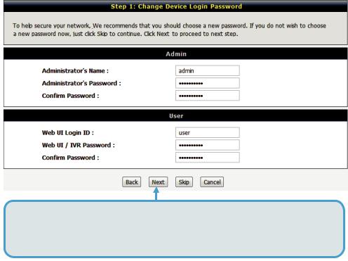
It is highly recommended to create a login ID and password to keep your gateway secure.
Click Next.
|
DVG-5008SG User’s Manual |
VoIP Gateway Configuration |
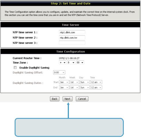
Enter a NTP server or use the default server.
Click Next.
|
DVG-5008SG User’s Manual |
VoIP Gateway Configuration |
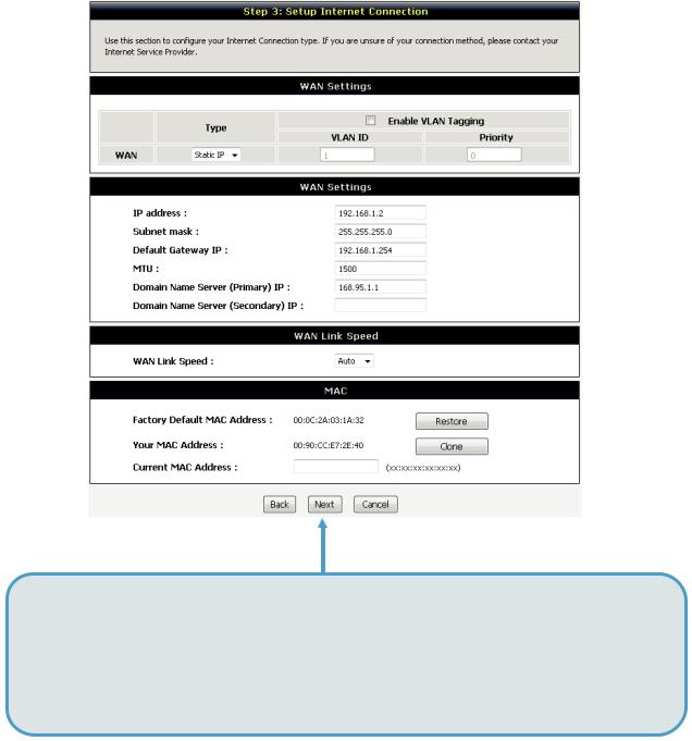
Select your Internet connection type:
DHCP – Most Cable ISPs or if you are connecting the DVG-5008SG behind a router. Static IP – Select if your ISP supplied you with your IP settings.
PPPoE – Most DSL ISPs.
PPTP – Select if required by your ISP.
Select Manual to manually enter IP address of DNS or select Auto if DNS is assigned by ISP. Click Next.

|
DVG-5008SG User’s Manual |
VoIP Gateway Configuration |
Register to the SIP Proxy Server by clicking Enable support of SIP Proxy Server. Enter Proxy Server IP/Domain and Port.
The Outbound Proxy Support is optional. To register, please click on the Outbound Proxy Support check box and enter Outbound Proxy IP/Domain and Port in it.
Registration by phone line: enter
Number, User ID/Account and Password supplied by your ITSP. Click on the Register check box to register to Proxy Server.
Click Next.
|
DVG-5008SG User’s Manual |
VoIP Gateway Configuration |
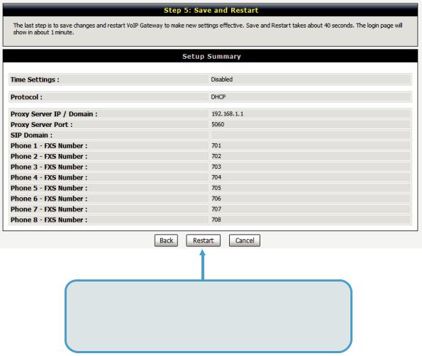
Setup is finished. Check the summary of your settings. To make new settings effective, you must click on the Restart button to reboot the DVG-5008SG.
Click Restart.
|
DVG-5008SG User’s Manual |
VoIP Gateway Configuration |
3. VoIP Gateway Web Configuration
3-1 Status
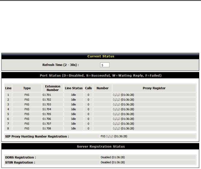
3-1-1 Current Status
For Port Status, it includes if each port registers to Proxy successfully, the last dialed number, how many calls each port has made since the VoIP Gateway is start, etc.
For Server Registration Status, it shows the registration status of DDNS, STUN and FXS Represent Number.
|
DVG-5008SG User’s Manual |
VoIP Gateway Configuration |
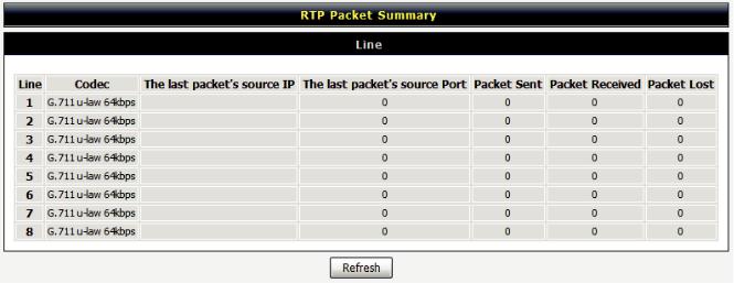
3-1-2 RTP Packet Summary
|
Status |
RTP Packet Summary |
Display the information of the last call made. Press Refresh button to get the latest RTP Packet Summary.
|
DVG-5008SG User’s Manual |
VoIP Gateway Configuration |
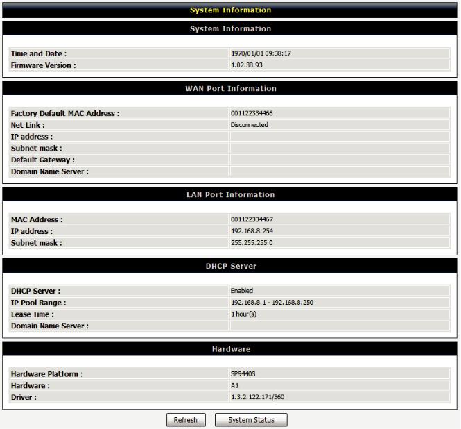
3-1-3 System Information
|
Status |
System Information |
For WAN Port Information, it shows IP address, subnet mask, default gateway and DNS server. If you use PPPoE to obtain IP, you will know if the IP is obtained through this method. If IP address, subnet mask, default gateway is blank, it means that the VoIP Gateway does not obtain IP.
For LAN Port Information, it shows LAN port IP, subnet mask, and the status of DHCP server.
For Hardware, it shows the hardware platform and driver version.
|
DVG-5008SG User’s Manual |
VoIP Gateway Configuration |
3-1-4 Routing Table
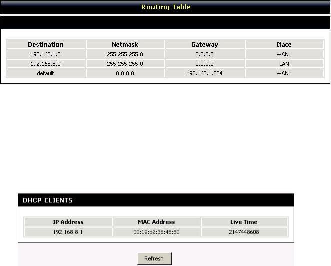
It displays routing table of DVG-5008SG.
3-1-5 LAN Client
The DHCP Clients table displayed LAN device that has already been assigned an address from DVG-5008SG. You can check if the DHCP client has obtain an IP address.
|
DVG-5008SG User’s Manual |
VoIP Gateway Configuration |
3-2 FXS Line Diagnostics
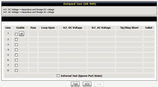
3-2-1 FXS Outward Test
FXS Line Diagnostics Æ FXS Outward Test
It allows operator to verify whether it is some problem on the cable between Phone Sets and DVG-5008SG.
Enable: Select the lines you want to test.
Including Channel In Used: Since the line test will interrupt a talking call, that DVG-5008SG will ignore the in used line. If you would like to test all the lines you select even it is in used, please tick this item.
Test: Click start to test.
ACO: Clear alarm indication of the last test result.
|
DVG-5008SG User’s Manual |
VoIP Gateway Configuration |
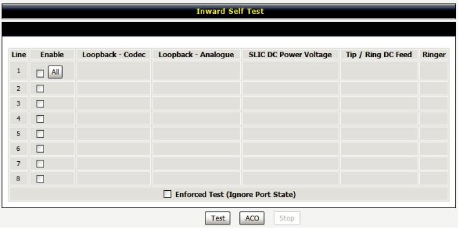
3-2-2 FXS Inward Self Test
FXS Line Diagnostics Æ FXS Inward Self Test
It allows operator to verify if it is some problem on the FXS chip set.
Enable: Select the lines you want to test.
Including Channel In Used: Since the line test will interrupt a talking call, that DVG-5008SG will ignore the in used line. If you would like to test all the lines you select even it is in used, please tick this item.
Test: Click start to test.
ACO: Clear alarm indication of the last test result.
|
DVG-5008SG User’s Manual |
VoIP Gateway Configuration |
3-3 General Settings
3-3-1 WAN
WAN (Wide Area Network) Settings are used to connect to your ISP (Internet Service Provider). The WAN settings are provided to you by your ISP and oftentimes referred to as «public settings». Please select the appropriate option for your specific ISP.
IP Configuration (Setting WAN Port)
There are five methods of obtaining a WAN port IP address:
1.DHCP, which means a Dynamic IP (Cable Modem)
2.Static IP
3.PPPoE (dial-up ADSL)
4.PPTP
Methods for using DHCP and PPPoE for obtaining an IP address may vary. If you are not familiar with creating a network connection, please contact your local ISP.
After selecting the suitable option, click Accept at the bottom of the screen to save the settings.
You need to save the changes and restart the VoIP Gateway to make the changes active. Saving the settings: Click MAINTENANCE and select Save/Restart in System from the left menu. Tick Save Settings and Restart, then click Accept. Wait for about 50 seconds before the VoIP Gateway obtaining an IP address by the method you selected.
Note: When the system has obtained a new IP address, and you are using a WAN port to enter the Web Configuration Screen, the new IP address has to be used before you can get connected to the VoIP Gateway. The same principle applies to the next two settings.
General Settings WAN
|
DVG-5008SG User’s Manual |
VoIP Gateway Configuration |
|
|
General Settings |
WAN |
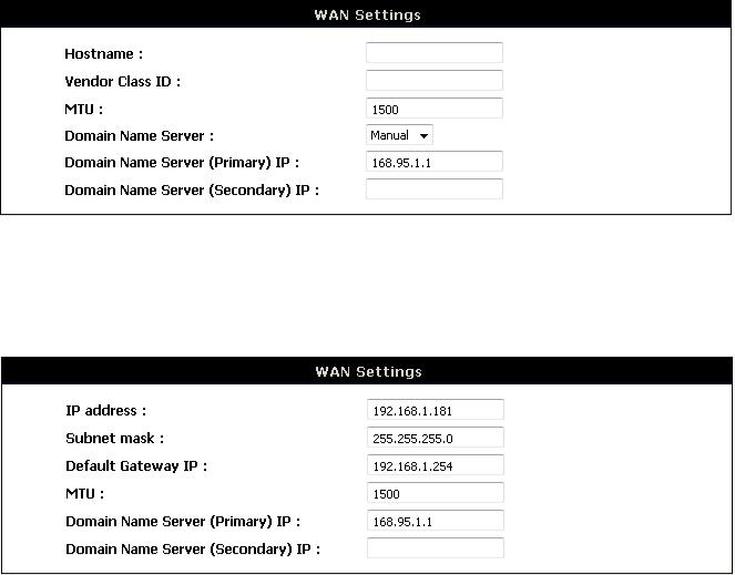
DHCP: Select this option if your ISP (Internet Service Provider) provides you an IP address automatically. Cable modem providers typically use dynamic assignment of IP Address. The Host Name field is optional but may be required by some Internet Service Providers.
General Settings WAN
Static IP: Select this option if your ISP (Internet Service Provider) provides you a Static IP address. Enter the IP address, Subnet Mask and Default Gateway IP.
![]()
|
DVG-5008SG User’s Manual |
VoIP Gateway Configuration |
|
|
General Settings |
WAN |
PPPoE: Select this option if your ISP requires you to use a PPPoE (Point-to-Point Protocol over Ethernet) connection. Enter the PPPoE Account, PPPoE Password and re-enter Password to confirm.
General Settings WAN
PPTP: Point-to-Point Tunneling Protocol (PPTP) is a WAN connection. Enter the IP Address, Subnet mask, PPTP Server, PPTP ID and Password.
|
DVG-5008SG User’s Manual |
VoIP Gateway Configuration |
|
|
General Settings |
WAN |
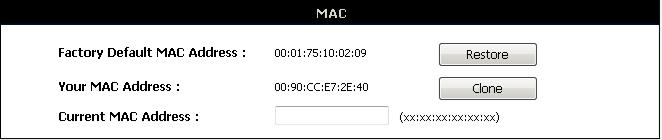
Factory Default MAC Address: The original MAC address of the VoIP Gateway. Your MAC Address: It is left blank as you log-in via the WAN port.
Current MAC Address: It shows the current MAC Address if you ever used the different MAC address from Factory Default MAC Address. You can click Clone to automatically copy the MAC address of the Ethernet Card installed in the computer used to configure the device.
Note: This is only necessary to fill the field if required by your ISP.
|
DVG-5008SG User’s Manual |
VoIP Gateway Configuration |
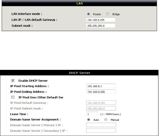
3-3-2 LAN
LAN Port Address: Enter the LAN IP address of the VoIP Gateway. It is also the default gateway for DHCP clients.
Subnet Make: Enter the subnet mask for DHCP clients.
Enable DHCP Server: This variable is to assign the IP address for the devices connected to LAN port of the VoIP Gateway.
IP Pool Starting Address: Enter the starting IP address for the DHCP server’s IP assignment. IP Pool Ending Address: Enter the ending IP address for the DHCP server’s IP assignment.
IP Pool Uses Other Default Gw: Check the box to assign different default gateway for DHCP clients.
IP Pool Default Gateway: Enter the new default gateway that is different from LAN IP of the VoIP Gateway.
IP Pool Subnet mask: Enter the new subnet mask. Lease Time: Enter the length of time for the IP lease.
Domain Name Server Assignment: Select Auto or Manual to get the IP address of Domain Name Server assigned by ISP or manually.
Domain Name Server IP: Enter the primary and secondary IP address of Domain Name Server if Domain Name Server Assignment is Manual. Otherwise, the VoIP Gateway will not be able to access hosts using hostnames instead of IPs.

|
DVG-5008SG User’s Manual |
VoIP Gateway Configuration |
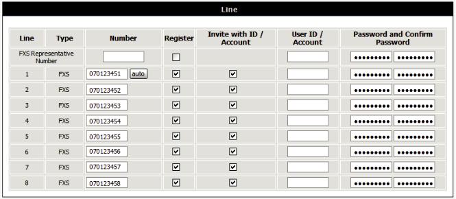
3-3-3 SIP
As there are various Proxy Server providers, according to RFC standard, it has designed the gateway to be compatible with them. If any registration problem occurs, please consult your Internet telephony Server Provider.
Enable Support of SIP Proxy Server / Soft Switch: Check the box to register the VoIP Gateway with SIP proxy server or soft switch.
FXS Representative Number registers to Proxy:
***
Number: Enter the representative number for Line 1-24. If the VoIP Gateway is configured to register with SIP proxy server, all the lines are using this number to call through SIP proxy server. It is the Caller ID for the called party when you make a VoIP call. If you register the VoIP Gateway to a SIP proxy server, then it should be the number that provided by SIP proxy server.
Register: Check the box to register with SIP proxy server.
User ID/Account: User ID/Account are usually the same as Number from most SIP proxy severs. Password: Enter password and re-enter to confirm.
Note: Please ensure if your VoIP Service Provider allows one account for multi-port using.
|
DVG-5008SG User’s Manual |
VoIP Gateway Configuration |
|
|
General Settings |
SIP |
Each line registers to Proxy independently:
Number: Enter the number, text or number and text in this field. It is the Caller ID for the called party when you make a VoIP call. If you register the VoIP Gateway to a SIP proxy server, then it should be the number that provided by SIP proxy server. Number and User ID/Account are usually the same from most SIP proxy severs. Each line has a number. And the number of each line is not reiteration.
Register: Check the box to register with SIP proxy server.
Invite with ID / Account: Check the box to call through SIP proxy server without registration. It is always ticked when Register is also ticked. Most VoIP Service Providers will interdict the connection without registration.
User ID/Account: User ID/Account are usually the same as Number from most SIP proxy severs. Password: Enter password and re-enter to confirm.

Прежде, чем начать
Должно быть, по крайней мере, следующее:
Должно быть, по крайней мере, следующее:
Подписка на пакет услуг мультисервисного провайдера
Подписка на пакет услуг мультисервисного провайдера
Это устройство может быть настроено с
помощью Internet Explorer или Netscape
Navigator, 6.x или выше, с поддержкой
Javascript
DVG-5008S
VoIP-шлюз
Компьютер с приводом CD-ROM и портом Ethernet, работающий под
управлением Windows
Компьютер с приводом CD-ROM и портом Ethernet, работающий под
управлением Windows
Широкополосный модем с поддержкой Ethernet
Широкополосный модем с поддержкой Ethernet
Проверьте содержимое комплекта поставки
Проверьте содержимое комплекта поставки
В комплект поставки входит следующее:
В комплект поставки входит следующее:
Если какой-либо из указанных предметов отсутствует, пожалуйста,
обратитесь к поставщику.
Если какой-либо из указанных предметов отсутствует, пожалуйста,
обратитесь к поставщику.
DVG-5008S — VoIP-шлюз
Телефонный кабель
Ethernet-кабель 5 категории
Компакт-диск
Использование источника
питания с иными
характеристиками может
привести к выходу из строя
устройства и лишению
гарантии.
Адаптер питания
постоянного тока 12 В
©2005 D-Link Systems, Inc. Все права защищены. Торговые марки или зарегистрированные
торговые марки являются собственностью соответствующих владельцев. Программное
обеспечение и спецификации были изменены без предварительного уведомления.
Маршрутизатор VoIP с портами FXS DVG-5008S.