Коммутаторы D-link представляют собой устройства, которые имеют хороший функционал, гарантирующий качественную передачу видео в режиме реального времени, расширенные диагностики кабеля, умеют работать с VoIP и системами видеонаблюдения, управляются через веб-интерфейс, telnet-интерфейс и через фирменную утилиту SmartConsole.
Устройства особенно удобны для нужд предприятий малого и среднего уровня. В данной ознакомительной статье рассматриваются вопросы первичной настройки и базовых функций коммутаторов D-link SmartPro серии DES/DGS.
РЕГИСТРАЦИЯ В WEB-ИНТЕРФЕЙСЕ УПРАВЛЕНИЯ
Чтобы начать настройку коммутатора — запустите браузер, установленный на компьютере и укажите IP-адрес, который определен для устройства.
URL в адресной строке должен выглядеть следующим образом: http://123.123.123.123, где вместо чисел 123 необходимо вставить реальный IP-адрес коммутатора.
По умолчанию коммутатор имеет IP адрес 10.90.90.90
На открывшейся странице нажмите Login. Откроется окно аутентификации
Оставьте поля User Name (Имя пользователя) и Password (Пароль) незаполненными и нажмите ОК. Это позволит зарегистрироваться в пользовательском Web-интерфейсе.
В разделе System в пункте password задайте пароль для администратора.

Рисунок 1 — Страница установки пароля
НАСТРОЙКА СЕТИ
В пункте System Settings в разделе ip-information зададим коммутатору статический ip-адрес. В разделе System Information корректное имя устройства. Для применения параметров нажмите apply. Пример заполнения см. ниже:

Рисунок 2 — Страница внесение данных сети
Для настройки сети по DHCP, в том же разделе, выставите соответствующий пункт.При необходимости возможно настроить имя хоста и выставить число попыток назначения ip-адреса. Для этого в поле DHCP Option 12 State выставите значение Enabled и заполните соответствующие поля.
НАСТРОЙКА VLAN
Заходим в настройки коммутатора, в меню слева выбираем раздел VLAN -> 802.1Q VLAN и переведем в состояние enabled.

Рисунок 3 — Страница активации и добавления виртуальной сети
Для создания нового влана нажмите Add.
В поле VID прописываем идентификатор, т.е. номер влана, а в поле VLAN Name — его имя.

Рисунок 4 — Страница конфигурации портов виртуальной сети
Теперь обратитесь на таблицу с портами. Если вам надо просто добавить порт в виртуальную сеть, то напротив его номера ставим галку «Untagged». Если нужно, чтобы сеть уходила через транковый порт на другой коммутатор (Uplink/Downlink порты), то напротив этого порта ставим галку «Tagged». Нажимаем кнопку «Apply».Готово, созданная нами виртуальная сеть добавлена.
Для сохранения изменений во вкладке меню Save выберете Save Configuration.

Рисунок 5 — Сохранение параметров коммутатора
Первоначальная настройка завершена.
ТЕХНОЛОГИЯ PoE
D-link коммутаторы, рассматриваемые в данной статье, оснащены технологией PoE. Что же это такое, и для чего нужно?

Рисунок 6 — Устройства, поддерживающие подключение по технологии РоЕ
PoE (Power over Ethernet) — технология, позволяющая подавать электропитание устройствам в сети по витой паре стандарта Ethernet. Данная технология используется для ip-телефонии, ip-камер и других устройств с целью исключения использования дополнительного кабеля питания. Технология не оказывает негативного влияния на качество передачи данных.
Данная технология обладает рядом преимуществ:
- Подключение в местах с ограниченным доступом.
- Подключение устройств при ограниченном количестве розеток на рабочих местах, число которых регулируется стандартами ИТ-безопасности.
- Позволяет управлять устройством (включать, выключать и перезагружать по питанию в случаях зависания, обновления или другой необходимости).
- PoE относится к слаботочным сетям. Максимальное напряжение, которое может выдаваться с одного порта, не превышает 60 вольт.
Настройки PoE в D-link расположены на следующих страницах раздела PoE:
1. PoE Global Settings

Рисунок 7 — Страница глобальных настроек РоЕ
Отображает текущий статус PoE, потребляемую и оставшуюся мощность, процент потребляемой мощности системы.
System Power Threshold: настраиваемый вручную порог мощности PoE 7,1 ~ 72 Вт.
Power Shut Off Sequence: определяет метод, используемый для отключения питания.
System Power Status: отображает состояние питания системы устройства:
- Total PoE Power Budget: отображает общий бюджет мощности PoE коммутатора.
- Power Used: отображает текущую используемую мощность PoE.
- Power Left: отображает остаточную мощность PoE
2. PoE Port Settings

Рисунок 8 — Страница настройки портов РоЕ
В таблице портов отображается состояние PoE, Port State, Priority, Power Limit, Power (W), Voltage(V), Current (mA), Classification, Status.
Вы можете выбрать From Port / To Port для управления PoE функциями порта устройства . Устройство автоматически отключит порты, если ток порта превысит 375 мА в режиме 802.3af.
From Port / To Port: указывает функцию PoE порта или портов.
State: выберите «Включено» или «Отключено».
Priority: настройте приоритет источника питания как «Low», «Normal» или «High» для назначенных портов.
Power Limit: функция позволяет вручную устанавливать ограничение мощности тока, передаваемого на PD.
Для защиты коммутатора и подключенных устройств функция power limit отключит PoE порта при перегрузке питания. Выберите «Class 1», «Class 2», «Class 3» или «Auto» для ограничения мощности.
Для применения настроек нажмите Apply.
Таким образом технология PoE обладает широкими коммуникационными возможностями, которые позволяют создавать сети с оборудованием разного типа и предназначения.
ВСТРОЕННЫЕ СРЕДСТВА ДИАГНОСТИКИ И СТАТИСТИКИ
В данном разделе рассматриваются возможности использования коммутаторов в части сбора статистической информации и диагностики кабеля.
Коммутаторы EasySmart приспособлены для сбора статистики как успешных, так и ошибочных пакетов данных. Ошибки на порту указывают на физические проблемы с кабелем или плохое соединение с коннектором. Коммутаторы данной серии позволяют провести раздельную диагностику кабелей, подключенных к портам. Для Для просмотра диагностики необходимо перейти в раздел «L2 Features» и открыть страницу «Cable diagnostics». Результаты диагностики приводятся для каждой пары подключенного кабеля.
По результатам диагностики выводятся следующие сообщения:
- OK – исправное состояние;
- Short in Cable – короткое замыкание;
- ЭOpen in Cable – кабель поврежден или не подключён на другой стороне;
- Mismatched – возникли ошибки при диагностике, требуется перезапустить тест на том же порту;
- Line Driver – обнаружено высокое электрическое сопротивление на другой стороне кабеля;
- Cable Fault Distance (meters) – расстояние от порта коммутатора до поврежденного участка (при длине кабеля менее 2 метров будет сообщение об отсутствии кабеля «No Cable»);
- Cable Length (meter) – при исправном кабеле (результат «OK») отобразит общую длину подключенного к порту кабеля
Страница статистики «Statistics» в настраиваемых коммутаторах WebSmart доступна в разделе «Monitoring». При нажатии на номер порта отображается его более подробная статистика.

Рисунок 9 — Страница статистики портов коммутатора
Подробная статистика порта отображается в следующих значениях счетчиков:
- «OutOctets» — количество переданных байтов;
- «OutUcastPkts» — количество переданных одноадресных пакетов;
- «OutNUcastPkts» — количество переданных многоадресных пакетов;а
- «OutErrors» — количество ошибок передачи;
- «LateCollisions» — количество случаев, когда коллизия зафиксирована после того, как в канал связи уже были переданы первые 64 байт (slotTime) пакета;
- «ExcessiveCollisions» — количество фреймов, которые не были переданы из-за избыточного количества коллизий;
- «InternalMACTransmitErrors» — количество фреймов, которые не были переданы успешно из-за внутренней ошибки передачи на уровне MAC;
- «InOctets» — количество принятых байтов;
- «InUcastPkts» — количество принятых одноадресных пакетов;
- «InNUcastPkts» — количество принятых многоадресных пакетов;
- «InDiscards» — количество пакетов, отклоненных в результате сбоя выделения памяти, или в результате сбоя контрольной суммы;
- «InErrors» — количество ошибок приема;
- «FCSErrors» — количество принятых фреймов с количеством байт, соответствующим длине, но не прошедших проверку контрольной суммы (FCS);
- «FrameTooLongs» — количество принятых пакетов с превышением максимально допустимого размера кадра;
- «InternalMACReceiveErrors» — количество фреймов, которые не были приняты успешно из-за внутренней ошибки приема на уровне MAC.
Страница диагностики «Cable Diagnostics» также доступна в разделе «Monitoring».

Рисунок 10 — Страница диагностики
Также в разделе «Monitoring» расположена страница системного лога «System Log». Для сохранения файла на компьютере, из списка выпадающего меню «Save», — выберите пункт «Save Log». Для сохранения файла нажмите кнопку «Backup Log». В результате будет сохранён текстовый файл «systemlog.log».
Таким образом мы провели первичную настройку коммутатора D-link, рассмотрели принцип работы технологии PoE и ее настраиваемые параметры на устройстве, ознакомились со встроенными инструментами диагностики и статистики.
Эти и другие настройки для наших клиентов мы осуществляем в рамках ИТ-аутсорсинга.
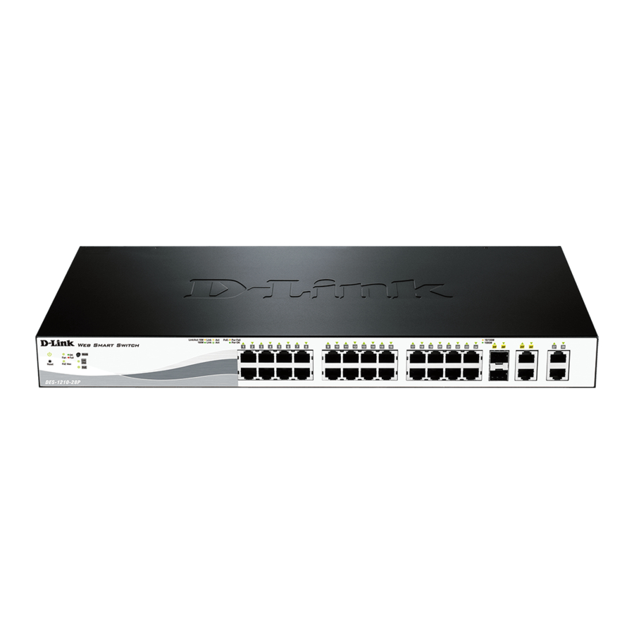
Умный управляемый коммутатор D-Link

Комплект поставки
Откройте картонную упаковку коммутатора и осторожно распакуйте ее содержимое. Если какой-либо элемент отсутствует или поврежден, обратитесь к местному дилеру D-Link для замены. В картонной коробке должны находиться следующие предметы:
- Один коммутатор DGS-1250-28X
- Один шнур питания переменного тока
- Один консольный кабель (RJ-45 — RS-232)
- Один комплект для монтажа в стойку (два кронштейна и винты)
- Четыре резиновые ножки с липкой основой
- Один комплект держателей шнура питания
- Одно руководство по быстрой установке
Руководство по установке
В этом разделе обсуждаются рекомендации по установке оборудования, которым должен следовать пользователь, чтобы правильно и безопасно установить этот коммутатор в соответствующей среде.
- Визуально осмотрите шнур питания и убедитесь, что он полностью прикреплен к разъему питания на коммутаторе и к электрической розетке, к которой подается питание.
- Установите коммутатор в достаточно прохладном и сухом месте с допустимыми диапазонами рабочей температуры и влажности.
- Устанавливайте коммутатор в месте, где отсутствуют генераторы сильного электромагнитного поля, такие как двигатели, вибрация, пыль и прямые солнечные лучи.
Установка коммутатора без стойки
Этот раздел используется для ознакомления пользователя с установкой коммутатора в области, отличной от стойки коммутатора. Прикрепите прилагаемые резиновые ножки к нижней части коммутатора. Обратите внимание, что в нижней части коммутатора должны быть отмечены блоки, указывающие, где прикрепить резиновые ножки. Эти отметки обычно находятся в каждом углу на нижней части устройства. Резиновые ножки амортизируют коммутатор, защищая корпус от царапин и предотвращая появление царапин на других поверхностях. Установите коммутатор на прочную ровную поверхность, способную выдержать вес коммутатора. Не ставьте на коммутатор тяжелые предметы. Сетевая розетка должна находиться в пределах 1.82 метра (6 футов) от коммутатора. Убедитесь, что коммутатор должным образом отводится тепла и вентилируется. Оставьте не менее 10 см (4 дюйма) пространства спереди, по бокам и сзади коммутатора для вентиляции.
Установка коммутатора в стандартную 19-дюймовую стойку
Этот раздел используется для помощи пользователю при установке коммутатора в стойку коммутатора. Коммутатор можно установить в стандартную стойку 19 ″ (1U) с помощью прилагаемых монтажных кронштейнов. Прикрепите монтажные кронштейны к сторонам коммутатора с помощью прилагаемых винтов.
Закрепите монтажные кронштейны в любом свободном пространстве стойки с помощью винтов, прилагаемых к стойке. Установка трансиверов в порты трансиверов
Коммутатор оснащен подключаемыми портами расширенного малого форм-фактора (SFP +), которые можно использовать для подключения к этому коммутатору различных других сетевых устройств, не поддерживающих стандартное кабельное соединение RJ-45. Эти порты обычно используются для подключения этого коммутатора к оптоволоконным соединениям и могут использоваться для подключения устройств к коммутатору на больших расстояниях. Максимальное расстояние, которое может достигать проводное соединение RJ-45, составляет 100 метров. Волоконно-оптические соединения могут охватывать несколько километров.
Включение (питание переменного тока)
Вставьте один конец шнура питания переменного тока в розетку коммутатора, а другой конец — в розетку местного источника питания.
Сбой питания (питание переменного тока)
В случае сбоя питания в качестве меры предосторожности отключите шнур питания от коммутатора. После восстановления питания снова вставьте шнур питания в розетку коммутатора.
Установка держателя шнура питания
Во избежание случайного отсоединения шнура питания переменного тока рекомендуется устанавливать фиксатор шнура питания вместе со шнуром питания. Шершавой стороной вниз вставьте ленту для стяжки в отверстие под розеткой. Вставьте шнур питания переменного тока в розетку коммутатора.
 Проденьте фиксатор через стяжку до конца шнура.
 Оберните стяжку держателя вокруг шнура питания и вставьте его в фиксатор держателя.
 Закрепите стяжку держателя, пока шнур питания не будет зафиксирован.
 Варианты управления
Этот коммутатор предоставляет платформы множественного доступа, которые можно использовать для настройки, управления и мониторинга сетевых функций, доступных на этом коммутаторе. В настоящее время доступны три платформы управления, которые описаны ниже.
Интерфейс командной строки (CLI)
Этим коммутатором можно управлять по внеполосному каналу с помощью консольного порта на передней панели коммутатора.
Управление на основе SNMP
Коммутатором можно управлять с помощью консольной программы, совместимой с SNMP. Коммутатор поддерживает SNMP v1, SNMPv2c и SNMPv3.
Web Пользовательский интерфейс (Web UI)
Компания Web Доступ к пользовательскому интерфейсу можно получить с любого запущенного компьютера. web программное обеспечение для просмотра. Этот интерфейс управления является более графическим представлением функций, которые могут быть viewed и настроен на этом коммутаторе.
Подключение к консольному порту
На передней панели коммутатора имеется консольный порт RJ-45 для подключения удаленной системы для мониторинга и настройки коммутатора. Для использования консольного порта RJ-45 необходимо следующее оборудование:
- Терминал или компьютер с последовательным портом RS-232 и программным обеспечением эмуляции терминала.
- Консольный кабель с штекером DB9 на одном конце и разъемом RJ-45 на другом.
Чтобы подключить консольный порт RJ-45 на коммутаторе к компьютеру:
- Подключите штекерный разъем DB9 на консольном кабеле (входит в комплект поставки коммутатора) к последовательному порту RS-232 на компьютере, на котором запущено программное обеспечение эмуляции терминала, затем вставьте разъем RJ-45 в консольный порт RJ-45 на передней панели коммутатора.
Чтобы настроить программное обеспечение эмуляции терминала следующим образом:
Вход в Web UI
Поддержанный Web браузеры:
- Microsoft Internet Explorer 8 или выше
- Firefox
- Google Chrome
- Safari
Чтобы получить доступ к Web UI, откройте стандартный web браузера, введите IP-адрес коммутатора в адресную строку браузера и нажмите клавишу ENTER. Чтобы получить доступ к Web Пользовательский интерфейс от обычных портов LAN, IP-адрес по умолчанию — 10.90.90.90 с маской подсети 255.0.0.0. При подключении к Web Пользовательский интерфейс коммутатора впервые введите имя пользователя и пароль (оба — admin) в соответствующие поля и нажмите «Войти».
![]()
Документы / Ресурсы
 |
Умный управляемый коммутатор D-Link [pdf] Руководство пользователя DGS-1250-28X, интеллектуальный управляемый коммутатор, 24 порта 10 100Base-T, 1000 порта SFP 4GBase-X, управляемый интеллектуальный коммутатор второго уровня |
Рекомендации
-
Contents
-
Table of Contents
-
Bookmarks
Quick Links
Related Manuals for D-Link Web Smart DES-1210-28P
Summary of Contents for D-Link Web Smart DES-1210-28P
-
Page 3: Table Of Contents
File … 14 Help … 15 Device Configuration… 16 Add(+), Delete(-) and Discover the device … 18 Device List… 18 Configuration … 20 Smart Wizard Configuration… 20 Password Settings… 20 SNMP Settings … 21 D-Link Web Smart Switch User Manual…
-
Page 4
Configuration > Spanning Tree > STP Global Settings… 48 Configuration > Spanning Tree > STP Port Settings … 49 QoS > Storm Control … 50 QoS > Bandwidth Control… 50 QoS > 802.1p/DSCP Priority Settings… 51 D-Link Web Smart Switch User Manual… -
Page 5
Appendix B — Technical Specifications … 75 Hardware Specifications … 75 Key Components / Performance … 75 Port Functions … 75 Physical & Environment … 75 Emission (EMI) Certifications … 75 Safety Certifications… 75 Features … 75 D-Link Web Smart Switch User Manual… -
Page 6
Table of Contents L2 Features … 75 VLAN … 75 QoS (Quality of Service)… 76 Security… 76 Green… 76 Management… 76 Appendix C – Rack mount Instructions … 77 D-Link Web Smart Switch User Manual… -
Page 7: About This Guide
Reproduction in any manner whatsoever without the written permission of D-Link Corporation is strictly forbidden. Trademarks used in this text: D-Link and the D-LINK logo are trademarks of D-Link Corporation; Microsoft and Windows are registered trademarks of Microsoft Corporation. Other trademarks and trade names may be used in this document to refer to either the entities claiming the marks and names or their products.
-
Page 8: Product Introduction
The intuitive SmartConsole easily allows customers to discover multiple D-Link web smart switches in the same L2 network segment. With this utility, users do not need to change the IP address of PC and provides easy initial setting of smart switches.
-
Page 9: Des-1210-08P
Port Link/Act LED (1-8): The Link/Act LED lights up with solid green indicate a network link through the corresponding port. Blinking indicates that the Switch is either sending or receiving data to the port. Reset: By pressing the Reset button the Switch will change back to the default configuration and all changes will be lost.
-
Page 10: Rear Panel
CAUTION: The MiniGBIC ports should use UL listed Optical Transceiver product, Rated Laser Class I. 3.3Vdc. Reset: By pressing the Reset button the Switch will change back to the default configuration and all changes will be lost. Rear Panel Power: The power port is where to connect the AC power cord.
-
Page 11: Rear Panel
When a port has amber light indicates that port is running on 10M or 100M. When it has a green light it is running on 1000M. Reset: Press the reset button to reset the Switch back to the default settings. All previous changes will be lost.
-
Page 12: Rear Panel
CAUTION: The MiniGBIC ports should use UL listed Optical Transceiver product, Rated Laser Class I. 3.3Vdc. Rear Panel Power: Connect the supplied AC power cable to this port. D-Link Web Smart Switch User Manual Figure 8 – DES-1210-52 Rear Panel…
-
Page 13: Hardware Installation
Rack Installation The switch can be mounted in an EIA standard size 19-inch rack, which can be placed in a wiring closet with other equipment. To install, attach the mounting brackets to the switch’s side panels (one on each side) and secure them with the screws provided (please note that these brackets are not designed for palm size switches).
-
Page 14: Step 3 — Plugging In The Ac Power Cord
(e.g. use of power strips).» Step 3 – Plugging in the AC Power Cord Users may now connect the AC power cord into the rear of the switch and to an electrical outlet (preferably one that is grounded and surge protected).
-
Page 15: Power Failure
Figure 13 – Plugging DES-1210-28/28P/52 into an outlet Power Failure As a precaution, the switch should be unplugged in case of power failure. When power is resumed, plug the switch back in. Figure 12 – Plugging the DES-1210-08P into an outlet…
-
Page 16: Getting Started
This chapter introduces the management interface of D-Link Web-Smart Switch. Management Options The D-Link Web Smart Switch can be managed through any port on the device by using the Web-based Management or through any PC using the SmartConsole Utility. Each switch must be assigned its own IP Address, which is used for communication with Web-Based Management or a SNMP network manager.
-
Page 17: Login Web-Based Management
Spanish, French, Italian, Japanese and Russian. By default, the password is admin and the language is English. Smart Wizard After a successful login, the Smart Wizard will guide you through essential settings of the D-Link Web Smart Switch. Please refer to Smart Wizard Configuration section for details. Web-based Management By clicking the Exit button in Smart Wizard, you will enter the Web-based Management interface.
-
Page 18
CD-Rom or DVD-Rom) and click OK. Follow the on-screen instructions to install the utility. Upon completion, go to Start > Programs > D-Link SmartConsole Utility and open the SmartConsole Utility. Connect the Smart Switch to the same L2 network segment of your PC and use the SmartConsole Utility to discover the Smart Switches. -
Page 19: Smartconsole Utility
4 SmartConsole Utility SmartConsole Utility The D-Link SmartConsole Utility allows the administrator to quickly discover all D-Link smart switches which are in the same domain of the PC, collect traps and log messages, and quick access to basic configurations of the switch.
-
Page 20: Log
File By clicking on this icon you will see below options: Figure 19 – SmartConsole Log Figure 20 – SmartConsole Trap Icon Description No new traps New traps was received D-Link Web Smart Switch User Manual…
-
Page 21: Help
4 SmartConsole Utility D-Link Web Smart Switch User Manual Figure 21 – SmartConsole File Monitor Save: Records the setting of the Device List as default for the next time the SmartConsole Utility is used. Monitor Save As: Records the setting of the Device List in an appointed filename and file path.
-
Page 22: Device Configuration
Device List. Device Settings Select a switch from the Device List. Click on this icon to launch the Device Settings window. Here you can configure the Product Name, IP Address, Gateway, Subnet Mask, System Name, Location, Trap Host IP, Switch Group Interval, and DHCP Client Setting of the Switch.
-
Page 23
DHCP Refresh: If a DHCP-client enabled switch in the Device List shows the default IP is still used, it means the device did not receive an IP address from the DHCP server successfully. Select that switch and click the DHCP refresh icon. -
Page 24: Add(+), Delete(-) And Discover The Device
4 SmartConsole Utility Web Access Select a switch from the Device List. Click this icon to launch your internet browser (eg. The Internet Explorer). Here you can configure the Switch through the Web-based Management utility. You may also get into the Web-based Management by double-clicking the device in the device list.
-
Page 25
Subnet Mask: Displays the Subnet Mask setting of the device. Gateway: Displays the Gateway setting of the device. Device Group Interval: Displays the intervals (in seconds) that the Switch will be discovered in the SmartConsole Device List Firmware version: Displays the current Firmware version of this device. -
Page 26: Configuration
5 Configuration D-Link Web Smart Switch User Manual Configuration The features and functions of the D-Link Web Smart Switch can be configured for optimum use through the Web-based Management Utility. Smart Wizard Configuration After a successful login, the Smart Wizard will guide you through essential settings of the D-Link Web Smart Switch.
-
Page 27: Snmp Settings
5 Configuration D-Link Web Smart Switch User Manual SNMP Settings The SNMP Settings feature allows you to quickly enable or disable the SNMP function and configure the SNMP community name. For the complete SNMP feature, please navigate to Setup Menu > System >…
-
Page 28: System Settings
System > System Settings”. The default setting of System IP address is Static. Select DHCP to have the switch obtain an IP address from a DHCP server in the network. Figure 32 – Configure System IP address in Smart Wizard NOTE: Changing the system IP address will disconnect you from the current connection.
-
Page 29: Web-Based Management
Finally, by clicking on the D-Link logo at the upper-left corner of the screen you will be redirected to the local D-Link website. D-Link Web Smart Switch User Manual…
-
Page 30: Tool Bar > Save Menu
The Tool Menu offers global function controls such as Reset, Reset System, Reboot Device, Configuration Backup and Restore, Firmware Backup and Upgrade. Reset Provide a safe reset option for the Switch. All configuration settings in non-volatile RAM will be reset to factory default except for the IP address. Reset System Provide another safe reset option for the Switch.
-
Page 31: Reboot Device
Click Restore after selecting the backup settings file you want to restore. Firmware Backup and Upload Allow for the firmware to be saved, or for an existing firmware file to be uploaded to the Switch. Two methods can be selected: HTTP or TFTP.
-
Page 32: Tool Bar > Smart Wizard
Tool Bar > Online Help The Online Help provides two ways of online support: Online Support Site will lead you to the D-Link website where you can find online resources such as updated firmware images; User Guide can offer an immediate reference for the feature definition or configuration guide.
-
Page 33
5 Configuration D-Link Web Smart Switch User Manual Figure 45 – User Guide Micro Site… -
Page 34: Function Tree
D-Link Web Smart Switch User Manual Function Tree All configuration options on the switch are accessed through the Setup menu on the left side of the screen. Click on the setup item that you want to configure. The following sections provide more detailed description of each feature and function.
-
Page 35: System > System Settings
5 minutes. Group Interval: The D-Link Web Smart Switch will routinely send report packets to the SmartConsole Utility in order to maintain the information integrity. The user can adjust the Group Interval to optimal frequency.
-
Page 36: System > Port Settings
(From Port and To Port), the Speed can be set for all selected ports, effective by clicking Apply. Press the Refresh button to view the latest information. D-Link Web Smart Switch User Manual Figure 50 – System > Trap Setting…
-
Page 37: System > Snmp Settings > Snmp Global State
Switch to other networking devices, a crossover cable must be used. This switch provides configurable MDI/MDIX function for users. The switches can set as an MDI port in order to connect to other hubs or switches without an Ethernet crossover cable.
-
Page 38: System > Snmp Settings > Snmp User Table
This page is used to maintain the SNMP user table for the use of SNMPv3. SNMPv3 allows or restricts users using the MIB OID, and also encrypts the SNMP messages sent out between users and Switch. User Name: Enter a SNMP user name of up to 32 characters.
-
Page 39: System > Snmp Settings > Snmp View Table
5 Configuration AuthPriv – Both authorization and encryption are required for packets sent between the Switch and SNMP manger. Notify View Name: Specify a SNMP group name for users that can receive SNMP trap messages generated by the Switch’s SNMP agent.
-
Page 40: System > Snmp Settings > Snmp Host Table
System > SNMP Settings > SNMP Engine ID The Engine ID is a unique identifier used to identify the SNMPv3 engine on the Switch. Input the Engine ID then click Apply to apply the changes and click Default resets to default value.
-
Page 41: System > Password Access Control
Figure 59 – System > SNMP Settings > SNMP Trap Setting System > Password Access Control Setting a password is a critical tool for managers to secure the Web-Smart Switch. After entering the old password and the new password two times, click Apply for the changes to take effect.
-
Page 42
5 Configuration D-Link Web Smart Switch User Manual You may change the name accordingly to the desired groups, such as R&D, Marketing, email, etc. Figure 62 – Configuration > 802.1Q VLAN > Default Setting Figure 63 – Configuration > 802.1Q VLAN > Add VID Figure 64 –… -
Page 43: Configuration > 802.1Q Vlan (Asymmetric Vlan)
VLAN 2 is configured to include ports 15-18, 20 (shared VLAN ports) and the set of ports to be separated from the other VLANs (for example, port 5). VLAN 3 and 4 are then configured to include D-Link Web Smart Switch User Manual Firewall, V1~V4…
-
Page 44: Configuration > 802.1Q Management Vlan
Configuration > 802.1Q Management VLAN The 802.1Q Management VLAN setting allows you to transfer the authority of the switch from the default VLAN to others created by users. This allows managing the whole network more flexible.
-
Page 45: Configuration > Voice Vlan > Voice Vlan Settings
From Port / To Port: A consecutive group of ports may be configured starting with the selected port. Auto Detection: Switch will add ports to the voice VLAN automatically if it detects the device OUI matches the Telephony OUI configured in Voice VLAN OUI Setting page. Use the drop-down menu to enable or disable the OUI auto detection function.
-
Page 46: Configuration > Voice Vlan > Voice Vlan Oui Setting
Similar as Voice VLAN, Auto Surveillance VLAN is a feature that allows you to automatically place the video traffic from D-Link IP cameras to an assigned VLAN to enhance the IP surveillance service. With a higher priority and individual VLAN, the quality and the security of surveillance traffic are guaranteed. The Auto Surveillance VLAN function will check the source MAC address / VLAN ID on the incoming packets.
-
Page 47: Configuration > Link Aggregation > Port Trunking
Auto Voice VLAN is also enabled to guarantee the quality of VoIP traffic. Component Type: Surveillance VLAN will automatically detect D-Link Surveillance Devices by default. There are another five surveillance components that could be configured to be auto-detected by surveillance VLAN.
-
Page 48: Configuration > Link Aggregation > Lacp Port Settings
Configuration > Link Aggregation > LACP Port Settings The LACP Port Settings is used to create port trunking groups on the Switch. The user may set which ports will be active and passive in processing and sending LACP control frames Figure 75 –…
-
Page 49: Configuration > Igmp Snooping
Click Apply to implement the changes made. Configuration > IGMP Snooping With Internet Group Management Protocol (IGMP) snooping, the Web Smart Switch can make intelligent multicast forwarding decisions by examining the contents of each frame’s Layer 2 MAC header. IGMP snooping can help reduce cluttered traffic on the LAN. With IGMP snooping enabled globally, the Web Smart Switch will forward multicast traffic only to connections that have group members attached.
-
Page 50: Configuration > Multicast Filtering Mode (For Des-1210-08P Only)
It also allows adjustments for controlling the frequency of IGMP traffic on a subnet. Default is 10 seconds. Querier State: D-Link Smart Switch is able to send out the IGMP Queries to check the status of multicast clients. Default is disabled.
-
Page 51: Configuration > Multicast Filtering Mode (For Des-1210-28/28P/52)
Port Mirroring is a method of monitoring network traffic that forwards a copy of each incoming and/or outgoing packet from one port of the Switch to another port where the packet can be studied. This enables network managers to better monitor network performances.
-
Page 52: Configuration > Sntp Settings > Time Settings
Configuration > SNTP Settings > Time Settings SNTP or Simple Network Time Protocol is used by the Switch to synchronize the clock of the computer. The SNTP settings folders contain two windows: Time Settings and TimeZone Settings. Users can configure the time settings for the switch, and the following parameters can be set or are displayed in the Time Settings page.
-
Page 53: Configuration > Sntp Settings > Timezone Settings
Local — Indicates that the system time is set locally by the device. SNTP — Indicates that the system time is retrieved from a SNTP server. Current Time: Displays the current date and time for the switch. If choosing SNTP for the clock source, then the following parameters will be available: SNTP First Server: Specify the IP address of primary SNTP server from which the system time is retrieved.
-
Page 54: Configuration > Spanning Tree > Stp Global Settings
Root Bridge, the Switch will start sending its own BPDU to all other switches for permission to become the Root Bridge. If it turns out that the Switch has the lowest Bridge Identifier, it will become the Root Bridge.
-
Page 55: Configuration > Spanning Tree > Stp Port Settings
STP can be set up on a port per port basis. In addition to setting Spanning Tree parameters for use on the switch level, the Switch allows for the configuration of groups of ports, each port-group of which will have its own spanning tree, and will require some of its own configuration settings.
-
Page 56: Qos > Storm Control
The Storm Control feature provides the ability to control the receive rate of broadcast, multicast, and unknown unicast packets. Once a packet storm has been detected, the Switch will drop packets coming into the Switch until the storm has subsided.
-
Page 57: Qos > 802.1P/Dscp Priority Settings
The following figure displays the status of Quality of Service priority levels of each port, higher priority means the traffic from this port will be first handled by the switch. For packets that are untagged, the switch will assign the priority depending on your configuration.
-
Page 58
Figure 90 – QoS > DSCP Priority Settings Select QoS Mode: D-Link Smart Switch allows the user to prioritize the traffic based on the 802.1p priority in the VLAN tag or the DSCP (Differentiated Services Code Point) priority in the IP header. Only one mechanism is selected to prioritize the packets at a time. -
Page 59: Security > Trusted Host
To delete the IP address simply click the Delete button, check the unwanted address, and then click Apply. Security > Safeguard Engine D-Link’s Safeguard Engine is a robust and innovative technology that automatically throttles the impact of packet flooding into the switch’s CPU. This function helps protect the Web-Smart Switch from being interrupted by malicious viruses or worm attacks.
-
Page 60: Security > Port Security
This page allows you to configure the SSL global state and the Ciphersuite settings. Select Enable or Disable and then click Apply to change the SSL state or the Ciphersuite settings of the Switch. By default, SSL is Disabled and all Ciphersuites are Enabled.
-
Page 61: Security > 802.1X > 802.1X Settings
EAP Request/Identity packet transmitted to the client. Default is 24 seconds. ReAuthEnabled: This function is to determine whether regular re-authentication will take place on this port(s). When the 802.1X function is enabled, the switch sends an EAP-request/identity packet to client. The ReAuthEnabled function is by default disabled.
-
Page 62: Security > Mac Address Table > Static Mac
SuppTimeout (1 – 65535 sec): This value determines timeout conditions in the exchanges between the Authenticator and the client. Default is 12 seconds. ServerTimeout (1 – 65535 sec): Sets the amount of time the switch waits for a response from the client before resending the response to the authentication server. Default is 16 seconds.
-
Page 63: Security > Mac Address Table > Dynamic Forwarding Table
Security > MAC Address Table > Dynamic Forwarding Table For each port, this table displays the MAC address learned by the Switch. To add a MAC address to the Static Mac Address List, click the Add checkbox, and then click Apply associated with the identified address.
-
Page 64
5 Configuration D-Link Web Smart Switch User Manual Figure 97 – Monitoring > Statistics Refresh All: Renews the details collected and displayed. Clear All Counters: To reset the details displayed. TxOK: Number of packets transmitted successfully. RxOK: Number of packets received successfully. -
Page 65: Monitoring > Cable Diagnostics
‧Test Failed means some other errors occurred during cable diagnostics. Please select the same port and test again. Cable Fault Distance (meters): Indicates the distance of the cable fault from the Switch port, if the cable is less than 2 meters, it will show “No Cable”.
-
Page 66: Acl > Acl Configuration Wizard
ACL > ACL Configuration Wizard Access Control List (ACL) allows you to establish criteria to determine whether or not the Switch will forward packets based on the information contained in each packet’s header. These criteria can be specified on a basis of MAC address, or IP address.
-
Page 67: Acl > Acl Profile List
Show Details: To display an ACL’s profile details. The ACL profile details are displayed below the ACL table. Show Rules: To show the access rule in this profile. D-Link Web Smart Switch User Manual Figure 102 – ACL > ACL Profile List…
-
Page 68
3) After the Profile ID has been created, it will go back to the main Access Profile List page, clicking the Edit / New Rules button to enter Access Rule List page. D-Link Web Smart Switch User Manual Figure 103 – Add Access Profile… -
Page 69
Source IP Address: Specify the Source IP address. DSCP: Specify the DSCP value. IP Protocol: The L4 protocol above IP. Possible values are ICMP, IGMP, TCP, and UDP. D-Link Web Smart Switch User Manual Figure 104 – Access Rule List Figure 105 – Add Access Rule… -
Page 70: Acl > Acl Finder
Destination Port: Specify the TCP or UDP destination port value. TCP Flag: Specify the TCP flag value. Ports: Specify the switch ports that you want to implement the access rule to. Action: Specify the ACL forwarding action matching the rule criteria. Permit is to forward packets if all other ACL criteria are met.
-
Page 71: Poe > Poe System Settings (Only For Des-1210-08P/28P)
This page allows you to configure the global PoE settings of the device and also displays current PoE status including System Budget Power, Support Total Power, Remainder Power, and The ratio of system power supply. D-Link Web Smart Switch User Manual Current power Figure 108 –…
-
Page 72: Time-Based Poe > Time Range Settings (Only For Des-1210-08P/28P)
LLDP devices. The Switch will store that information in the Management Information Base (MIB); SNMP utilities can learn about the network topology by getting the MIB information from each LLDP device.
-
Page 73: Lldp > Lldp Remote Port Information (Only For Des-1210-08P/28P)
Click << Back to return to the previous page. Figure 111 – LLDP > LLDP Global Settings Figure 112 – LLDP > LLDP Remote Port Information Figure 113 – LLDP > LLDP Remote Port Information D-Link Web Smart Switch User Manual…
-
Page 74: Lldp > Lldp-Med Settings (Only For Des-1210-28P)
5 Configuration D-Link Web Smart Switch User Manual LLDP > LLDP-MED Settings (Only for DES-1210-28P) LLDP-MED (Link Layer Discovery Protocol-Media Endpoint Discovery) is an enhancement of LLDP. It improves the LLDP operation between endpoint devices such as IP phones and APs. LLDP-MED supports features such as Auto-discovery of LAN policies and device location discovery.
-
Page 75: Command Line Interface
6 Command Line Interface Command Line Interface The D-Link Web Smart Switch allows a computer or terminal to perform some basic monitoring and configuration tasks by using the Command Line Interface (CLI) via TELNET protocol. To connect a switch via TELNET: 1.
-
Page 76: Upload
6 Command Line Interface firmware_fromTFTP cfg_fromTFTP tftp://ip-address/ filename Upload The upload command is used to upload the firmware file or a Switch configuration file to a TFTP server. Syntax upload firmware_toTFTP tftp://ip-address/filename } Parameters Parameter firmware_toTFTP cfg_toTFTP tftp://ip-address/ filename Config ipif system The config ipif system command sets the IP address of the switch.
-
Page 77: Logout
This command checks if another IP address is reachable on the network. You can ping the IP address connected to through the managed VLAN (VLAN 1 by default), as long as there is a physical path between the switch and the target IP equipment. By default, Switch sends five pings to the target IP.
-
Page 78: Reset
DES-1210-28P> Config account admin password The command sets the administrator password. Syntax config account admin password <passwd> D-Link Web Smart Switch User Manual Figure 120 – The reboot command Figure 121 – The reset config command : Static : 172.17.5.214 : 255.255.255.0…
-
Page 79: Save
The command saves the configuration changes to the memory. Syntax save Example DES-1210-28P> save Building configuration … [OK] DES-1210-28P> Debug info This command displays the ARP table and MAC FDB of the Switch. Syntax debug info Example DES-1210-28P> debug info % ARP table : Address Hardware Address ——- —————- 172.17.5.85…
-
Page 80: Appendix A — Ethernet Technology
Appendix A — Ethernet Technology Appendix A — Ethernet Technology This chapter will describe the features of the D-Link Web Smart Switch and provide some background information about Ethernet/Fast Ethernet/Gigabit Ethernet switching technology. Gigabit Ethernet Technology Gigabit Ethernet is an extension of IEEE 802.3 Ethernet utilizing the same packet structure, format, and support for CSMA/CD protocol, full duplex, and management objects, but with a tenfold increase in theoretical throughput of over 100-Mbps Fast Ethernet and a hundredfold increase over 10-Mbps Ethernet.
-
Page 81: Appendix B — Technical Specifications
— DEM-210 (100BASE-FX, 15km) — DEM-211 (100BASE-FX, 2km) WDM Transceivers Supported: — DEM-330T (1000Base-BX,TX-1550/RX- 1310nm, 10km) — DEM-330R (1000Base-BX,TX-1310/RX- 1550nm, 10km) D-Link Web Smart Switch User Manual — DEM-331T (1000Base-BX,TX-1550/RX- 1310nm, 40km) — DEM-331R (1000Base-BX,TX-1310/RX- 1550nm, 40km) — DEM-220T (100Base-BX, TX-1550/RX- 1310nm, 20km)
-
Page 82: Qos (Quality Of Service)
LLDP-MED (DES-1210-28P only) Trap setting for destination IP, system events, fiber port events, twisted-pair port events Port access control Web-based configuration restoration Web-based firmware backup/restore Firmware upgrade using SmartConsole Utility & Web-based management Reset, Reboot D-Link Web Smart Switch User Manual backup…
-
Page 83: Appendix C — Rack Mount Instructions
Appendix C – Rack mount Instructions D-Link Web Smart Switch User Manual Appendix C – Rack mount Instructions Safety Instructions — Rack Mount Instructions — The following or similar rack-mount instructions are included with the installation instructions: A) Elevated Operating Ambient — If installed in a closed or multi-unit rack assembly, the operating ambient temperature of the rack environment may be greater than room ambient.